US6791592B2 - Printing a code on a product - Google Patents
Printing a code on a productDownload PDFInfo
- Publication number
- US6791592B2 US6791592B2US10/454,025US45402503AUS6791592B2US 6791592 B2US6791592 B2US 6791592B2US 45402503 AUS45402503 AUS 45402503AUS 6791592 B2US6791592 B2US 6791592B2
- Authority
- US
- United States
- Prior art keywords
- printing
- pixels
- product
- printing beam
- code
- Prior art date
- Legal status (The legal status is an assumption and is not a legal conclusion. Google has not performed a legal analysis and makes no representation as to the accuracy of the status listed.)
- Expired - Lifetime
Links
Images


Classifications
- B—PERFORMING OPERATIONS; TRANSPORTING
- B41—PRINTING; LINING MACHINES; TYPEWRITERS; STAMPS
- B41M—PRINTING, DUPLICATING, MARKING, OR COPYING PROCESSES; COLOUR PRINTING
- B41M5/00—Duplicating or marking methods; Sheet materials for use therein
- B41M5/26—Thermography ; Marking by high energetic means, e.g. laser otherwise than by burning, and characterised by the material used
- B—PERFORMING OPERATIONS; TRANSPORTING
- B41—PRINTING; LINING MACHINES; TYPEWRITERS; STAMPS
- B41J—TYPEWRITERS; SELECTIVE PRINTING MECHANISMS, i.e. MECHANISMS PRINTING OTHERWISE THAN FROM A FORME; CORRECTION OF TYPOGRAPHICAL ERRORS
- B41J2/00—Typewriters or selective printing mechanisms characterised by the printing or marking process for which they are designed
- B41J2/435—Typewriters or selective printing mechanisms characterised by the printing or marking process for which they are designed characterised by selective application of radiation to a printing material or impression-transfer material
- B41J2/47—Typewriters or selective printing mechanisms characterised by the printing or marking process for which they are designed characterised by selective application of radiation to a printing material or impression-transfer material using the combination of scanning and modulation of light
- G—PHYSICS
- G06—COMPUTING OR CALCULATING; COUNTING
- G06K—GRAPHICAL DATA READING; PRESENTATION OF DATA; RECORD CARRIERS; HANDLING RECORD CARRIERS
- G06K1/00—Methods or arrangements for marking the record carrier in digital fashion
- G06K1/12—Methods or arrangements for marking the record carrier in digital fashion otherwise than by punching
- G06K1/126—Methods or arrangements for marking the record carrier in digital fashion otherwise than by punching by photographic or thermographic registration
Definitions
- the inventionrelates generally to a printing system.
- the inventionrelates to a printing system having a laser for printing on a product positioned adjacent to the printing system.
- codesoften include information which is unique to the time and place that the product is manufactured. For instance, many code communicate a batch number associated with a product. Many codes go further and indicate the actual time and date of manufacture. Since these codes are unique to the actual manufacturing parameters, the code can not be pre-printed on the label for the product. Hence, the code must often be printed on the label after the product is manufactured.
- the inventionrelates to a method for printing on a material.
- the methodincludes providing a printing system having a laser source for producing a printing beam and directing the printing beam to a plurality of locations on a material.
- the methodalso includes adjusting a dwell time of the printing beam at the one or more location so as to form a spot at each location.
- Another embodiment of the methodincludes providing a printing system for printing a code on a product which is adjacent to the printing system and which is moving in a direction relative to the printing system.
- the codeis constructed from a plurality of pixels.
- the methodalso includes prioritizing the order in which the pixels are printed such that the pixels are printed in a direction which is opposite to the direction which the product moves.
- Another embodiment of the methodincludes providing a printing system for printing a code on a product moving in a direction.
- the codeis constructed from a plurality of pixels in a first data set indicating the positions of the pixels.
- the methodalso includes generating a corrected data set indicating the position that each pixel would occupy if each pixel were moved at the velocity of the product until the pixel was printed.
- the methodfurther includes printing the code according to the corrected data set.
- Yet another embodiment of the methodincludes providing a printing system having a laser source for producing a printing beam and directing the printing beam so as to form a code on the material.
- the methodalso includes changing the amount of time required to form the code on the product.
- Still another embodiment of the methodincludes providing a printing system for printing an alphanumeric code on a product moving in a direction, the code being constructed from a plurality of pixels.
- the methodalso includes printing pixels on the product in a two dimensional trace so as to form the code on the product.
- the inventionalso relates to a printing system.
- the printing systemincludes a laser source for producing a printing beam and electronics for directing the printing beam to a plurality of locations on a material.
- the printing systemalso includes electronics for adjusting a dwell time of the printing beam at the one or more location so as to form a spot at each location.
- Another embodiment of the systemincludes a laser configured to produce a printing beam for printing a code on a product.
- the laseris at most a 25 Watt laser.
- a housingincludes a printing beam exit member through which the printing beam exits the housing.
- An optics assemblyis positioned within the housing. The optics assembly focussing the printing beam on a product which is adjacent to the housing.
- a further embodiment of the systemincludes a laser for printing a code on a product moving in a direction.
- the codeis constructed from a plurality of pixels in a first data set which indicates the positions of the pixels.
- the systemalso includes electronics for generating a corrected data set which indicates the position that each pixel would occupy if each pixel were moved at the velocity of the product until the pixel was printed.
- the systemalso includes electronics for printing the code according to the corrected data set.
- Yet another embodiment of the systemincludes a laser for printing a code on a product which is adjacent to the printing system and moving in a direction relative to the printing system.
- the codeis constructed from a plurality of pixels.
- the systemalso includes electronics for prioritizing the order in which the pixels are printed such that the pixels are printed in a direction which is opposite to the direction which the product moves.
- Another embodiment of the systemincludes a laser source for producing a printing beam and electronics for directing the printing beam so as to form a code on the material.
- the systemalso includes electronics for changing the amount of time required to form the code on the product.
- Still another embodiment of the systemincludes a laser for printing an alphanumeric code on a product that is adjacent to the printing system and moving in a direction relative to the printing system.
- the codeis constructed from a plurality of pixels.
- the systemalso includes electronics for printing pixels on the product so as to form the code on the product, the pixels being printed in a two dimensional trace.
- FIG. 1Ais a sideview of a printing system according to the present invention.
- FIG. 1Bis a cross section of the printing system looking down on to the printing system.
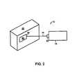
- FIG. 2illustrates the printing system forming a print zone upon a product.
- FIG. 3Ais a sideview of a printing system used in conjunction with a product line which temporarily stops the product in front of the printing system.
- FIG. 3Bis a sideview of a printing system used in conjunction with a product line which continuously moves the product in front of the printing system.
- FIG. 3Cis a topview of a printing system used in conjunction with a product line which continuously moves the product in front of the printing system.
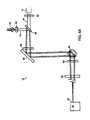
- FIG. 4Aillustrates an optical assembly for use in a printing apparatus according to the present invention.
- FIG. 4Bis a sideview of a plurality of mirrors configured to steer a printing beam produced by the printing system from one location to another on a product where a code is to be formed.
- FIG. 4Cillustrates the relationship between the optics assembly and the housing.
- FIG. 4Dillustrates the non-linear nature of a lens used in the optics assembly.
- FIG. 4Eillustrates a bearing which allows a printing beam exit member of the printing system to be rotated relative to a housing of the printing system. The rotatability of the printing beam exit member relative to the housing allowing a printing beam transmitted through the printing beam exit member to be aimed at a desired position on a product.
- FIG. 5Ais a sideview of a printing beam being incident on a material at a location where a spot is to be formed on the material.
- FIG. 5Bis a perspective view of a printing beam being incident on a material at a location where a spot is to be formed on the material.
- FIG. 5Cis a sideview of a material after the printing beam has formed a spot in the material.
- FIG. 5Dis a perspective view of a material after the printing beam has formed a spot in the material.
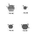
- FIGS. 6A-6Dillustrate formation of pixels having different sizes.
- FIG. 7Aillustrates an array of possible pixels which are selected to form a symbol within the array.
- FIG. 7Billustrates the symbol of FIG. 7A printed on a product.
- FIG. 8Aillustrates an aperture through which limits the area within which the printing system is able to print.
- FIG. 8Billustrates a symbol to be printed on a product continuously moving in front of the printing system.
- the symbolincludes a plurality of pixels arranged in columns. The order that the columns are printed is prioritized in a direction opposite of the direction which the product moves.
- FIG. 8Cillustrates a symbol to be printed on a product continuously moving in front of the printing system.
- the symbolincludes a plurality of pixels. The order that each pixel is printed is prioritized.
- FIG. 9Aillustrates conversion of a code to a corrected code.
- the correct codeis an image of the code which illustrates where the pixels of the code should be printed on a moving product in order for the code to appear as the uncorrected code.
- FIG. 9Billustrates the code being converted to a corrected code.
- FIG. 9Cillustrates the corrected code
- FIG. 9Dillustrates the code formed on the product after the corrected code is printed on the product while the product is continuously moved past the printing system.
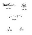
- FIG. 10Aillustrates conversion of a pixel to a corrected pixel.
- the correct pixelbeing an image of the pixel which illustrates where the spots of the pixel should be printed on a moving product in order for the pixel to appears as the uncorrected pixel.
- FIG. 10Billustrates the corrected pixel
- FIG. 10Cillustrates the pixel formed on the product after the corrected pixel is printed on the product while the product is continuously moved past the printing system.
- FIG. 10Dillustrates a spot formed on a stationary product.
- FIG. 10Eillustrates the spot of FIG. 10D formed on a product as the product is moving.
- FIG. 11Aillustrates the relationship between the product, the print trigger, the printing system and the print area.
- FIG. 11Billustrates the leading edge of a print area.
- the inventionrelates to a printing system for printing a code on a product positioned adjacent to the printing system.
- the printing systemincludes a laser for producing a printing beam and an optics assembly for steering the printing beam from one location to another location on the product.
- the printing systemincludes electronics for adjusting the time that the printing beam dwells at each location. This dwell time is adjusted such that the printing beam causes a spot to be formed at each location.
- the locationscan be arranged such that the spots form a pixel on the product.
- the pixelsin turn can be arranged to form the symbols of a code.
- the symbols of the codecan be the symbols which are available in word processing programs such as alphanumeric symbols and any other symbols used to identify a product batch, date, etc.
- the codecan be readable text such as a product names or identifiers.
- the codeneed not be alphanumeric and can include symbols which are not produced by typical word processing programs. For instance, the code can be a bar code.
- the products for use with the printing systemcan be products to be sold retail or packaging of retail products. Further, the products can be products which are sold to other businesses. Examples of products include pharmaceuticals, pharmaceutical packaging, food packaging, cosmetics, food such as eggs, dairy products, ice cream, computer components, automotive components, medical devices, detergents and beverages such as soft drinks and wines.
- the codecan be formed in multiple locations on a product.
- plastic medicine bottlescan have one code printed directly on the plastic bottle and another code formed on the label attached to the plastic bottle.
- the codeis constructed from a plurality of spots.
- the spotis formed on the product by altering an optical characteristic of the material at the location where the printing beam is incident on the product.
- the printing beamcan alter a variety of optical characteristics of a product.
- the printing beamcan cause one or more layers of material to be ablated so the underlying layers are visible. Since upper layers of a material often have an ink layer on paper, removal of the ink layer leaves a spot where the paper is visible against the surrounding ink layer.
- the refractive characteristics of a materialcan also be altered.
- the printing beamcan be used to print a code on a plastic such as a soft drink bottle. The printing beam alters the refractive characteristics of the plastic. The code is easily visible since the eye can pick up the sections having contrasting refractive properties. Additionally, the printing beam can etch certain materials.
- the printing systememploys a laser in order to print on the product, there is no need for consumables such as inks and solvents. Accordingly, the printing system can reduce the costs and complexity associated with printing a code on a product.
- the time that the laser dwells at each locationcan be increased to compensate for reductions in the power of the laser.
- a low powered lasercan be employed in the printing system.
- the laseris a CO 2 air cooled laser.
- the laseris at most a 25 Watt laser, in other instances the laser is at most a 20 Watt laser, in other instances the laser is at most a 15 Watt laser and in still other instances the laser is at most a 13 Watt laser.
- the lasercan be a low power laser
- the laser, optics assembly and associated electronicscan be mounted in a housing having a size on the order of an ink jet printer.
- the ability to adjust the dwell timemeans that the printing system according to the present overcomes the size and space challenges associated with traditional printing systems which employ a laser.
- the printing system according to the present inventionis an ideal substitute for the ink jets used to print codes on products.
- the printing system according to the present inventionis ideal for printing on products that are moving such as the products in a production line. Because these products are moving relative to the system, there is a limited amount of time available for printing on each product.
- the printing system according to the present inventionincludes electronics for varying the amount of time required to print the code on the product. For instance, the printing system according to the present invention includes electronics for changing the density of pixels that define the code. Codes having a reduced pixel density can be printed more quickly than codes with an increased pixel density. Further, the printing system according to the present invention includes electronics for changing the size of the pixels that define the code. Smaller pixels require less printing time. Additionally, the dwell time of the printing system can be changed as noted above. The ability to change the time required to print a code allows the printing system to be used in conjunction with an increased number of production lines.
- FIGS. 1A and 1Billustrate a printing system 10 for printing on a product positioned adjacent to the printing system.
- FIG. 1Ais a sideview of the printing system 10 while FIG. 1B is a cross sectional top view of the apparatus.
- the printing system 10includes a laser 12 for producing a printing beam 14 .
- Any laser 12can be used in the printing system.
- a low powered lasercan be employed in the printing system.
- the lasercan be a CO 2 air cooled laser. In some instances the laser is at most a 25 Watt laser, in other instances the laser is at most a 20 Watt laser, in other instances the laser is at most a 15 Watt laser and in still other instances the laser is at most a 13 Watt laser.
- the printing beam 14 from the energy sourcepasses through an optics assembly 18 and is incident on a material 20 such as the material 20 used in product 22 packaging.
- a material 20such as the material 20 used in product 22 packaging.
- the time that the beam is incident on the material 20can be adjusted such that the beam causes a spot to be formed on the material 20 .
- the optics assembly 18includes components for altering the direction of the printing beam 14 . These components can be controlled to steer the printing beam 14 from one location to another location so as to create a spot at each of the locations. As will be described in more detail below, the spots can be arranged to form one or more pixels 88 on the material 20 . Additionally, these pixels 88 can be arranged to form one or more symbols on the material 20 . These symbols can be an alphanumeric code such as the code printed on a product 22 or on the label a product 22 .
- the printing system 10also includes electronics 26 in communication with the energy source and the optics assembly 18 .
- the electronics 26can includes one or more processors for providing the functionality to the printing system 10 .
- Suitable processorsinclude, but are not limited to, microprocessors, digital signal processors (DSP), integrated circuits, application specific integrated circuits (ASICs), logic gate arrays and switching arrays.
- the electronics 26can also include one or more memories for storing instructions to be carried out by the one or more processors and/or for storing data developed during operation of the printing system 10 . Suitable memories include, but are not limited to, RAM and electronic read-only memories (e.g., ROM, EPROM, or EEPROM).
- the electronics 26control the operation of the laser 12 and the optics assembly 18 .
- the electronics 26can control the optics assembly 18 so as to adjust the direction of the printing beam 14 , the length of time that the printing beam 14 dwells at a location on the material 20 where a spot is to be formed, the speed that the printing beam 14 moves between each location where the beam dwells, the size of pixels 88 used to create visually recognizable symbols, the selection of symbols created, etc.
- the electronics 26can optionally be in communication with a user interface 30 .
- the user interface 30can be remote from the housing 16 , attached to the housing 16 and/or detachable from the housing 16 .
- a suitable user interface 30can include an alphanumeric keyboard and a display.
- the user interface 30can be used to program the electronics 26 and/or set printing parameters. For instance, the user interface 30 can be used to manually control the time that the printing beam 14 dwells at a single location on the material 20 , the size of the pixels 88 used to form a visually observable symbol, the type and/sequence of symbol which are formed, etc.
- the user interface 30can also be used to manually activate the printing system 10 .
- the user interface 30can include a print key which causes the printing system 10 to print on the material 20 .
- the electronics 26can also be in communication with one or more sensors 31 .
- These sensorscan provide the electronics with information about the products on which the printing system is to print.
- the sensors 31can indicate the location of a product relative to the printing system, the direction that a product is moving and when a moving product has been stopped and when a product is in the correct position to be printed upon.
- Suitable sensors 31include, but are not limited to, a speed sensor for detecting the speed and/or direction that a product is moving, a location sensor for indicating when a product is positioned in front of the sensor 31 .
- the printing system 10includes a printing beam exit member 32 through which the printing beam 14 exits the housing 16 .
- the printing beam exit member 32can be as simple as an opening in the housing 16 or an immobile window mounted in the housing 16 .
- the printing beam exit member 32can be moved relative to the housing 16 as illustrated by the arrow labeled A.
- the printing beam 14can be manually aimed toward a particular position on the material 20 by manipulating the printing beam exit member 32 .
- the housingcan also be compact.
- the housingcan have a volume of less than 1200 cubic inches.
- the housinghas a volume less than 900 cubic inches and in other instances, the housing has a volume less than 1200 inches.
- the housinghas a length, L, less than 25 inches, a width, W, less than 10 inches and a height, H, less than 5 inches.
- the housinghas a length, L, less than 23.5 inches, a width, W, less than 7.5 inches and a height, H, less than 4 inches.
- the housingincludes the print beam exit member.
- the small sizeis also associated with a low weight.
- the housing and the enclosed componentsweighs less than 30 pounds. In some instances, the housing and the enclosed components weigh less than 25 pounds and in other instances, the housing and the enclosed components weigh less than 22 pounds.
- This weightdoes not include the weight of components which are remote from the housing. For instance, this weight does not include user interfaces which are not integral to the housing. Additionally, this weight does not include the weight of any sensors with which the printing system is in communication but which are not integral with the housing.
- FIG. 2illustrates another embodiment of the printing system 10 .
- the printing system 10can include components for defining a print zone 34 on the material 20 .
- the printing system 10can project a rectangle onto the material 20 as illustrated in FIG. 2 .
- the printing system 10forms the symbol of the code within the print zone 34 .
- the print zone 34is formed on the material 20 and the operator adjusts the beam outlet member so that the print zone 34 appears at the desired location on the material 20 .
- the user interface 30is then used to activate print within the print zone 34 .
- the operator of the printing system 10can select where the printing mechanism prints on the material 20 by ensuring that the print zone mark appears in the desired print location.
- Other suitable print zone 34 marksinclude, but are not limited to, marks at the four corners of a print zone 34 , a mark positioned in the center of the print zone 34 , and a dashed line around the print zone 34 .
- the electronics 26control the size and geometry of the print zone 34 .
- the electronics 26can match the size and shape of the symbols to be printed on the material 20 .
- the electronics 26can enlarge the print zone 34 so the code will be formed entirely within the print zone 34 .
- an increase in the size of the codewill not result in erroneous positioning of the code on the material 20 .
- the printing system 10can print on a stationary product 22 , however, the printing system 10 is configured to print on packaging located on a product line 36 which moves the product 22 relative to the printing system 10 .
- FIG. 3Aillustrates a printing system 10 in operation with a product line 36 which temporarily stops the product 22 in front of the printing system 10 .
- the printing system 10is in communication with a print trigger 38 which detects when one of the products 22 is positioned in front of the print trigger 38 .
- a suitable print trigger 38includes a device which produces a light beam. The device can be set up next to the product line 36 so that the product 22 disrupts the beam as the product 22 travels along the product line 36 .
- the printing system 10can monitor the device to determine when a product 22 has disrupted the beam.
- the print trigger 38can be positioned such that when it has been triggered, the product 22 is correctly positioned for printing on the product 22 .
- the print trigger 38can be positioned such that when it has been triggered, a time delay must pass before the product 22 is correctly positioned for printing upon the product 22 .
- the printing system 10is also in communication with a stop mechanism 40 which stops each product 22 in front of the printing system 10 .
- the stop mechanism 40is withdrawn to allow the products 22 to move along the product line 36 .
- the movementcan be the result of one or more mechanical forces or one or more natural forces such as gravity.
- the products 22pass before the printing system 10 on the product line 36 .
- the printing system 10monitors the print trigger 38 to determine when a product 22 has moved in front of the print trigger 38 .
- the printing system 10waits a pre-set delay to let the product 22 be pressed against the stop mechanism 40 and then prints the symbols on the packaging. As a result, the product 22 remains stationary while the printing system 10 prints the code on the packaging.
- the printing system 10activates the stop mechanism 40 so the product 22 is again able to move.
- the printing mechanismmonitors the print trigger 38 to find a gap between products 22 . Once a gap is found, the printing system 10 activates the stop mechanism 40 to stop the next product 22 and again monitors the print trigger 38 to detect when the next product 22 has moved in front of the print trigger 38 .
- FIGS. 3B and 3Cillustrates the printing system 10 in use with a product line 36 which continuously moves the product 22 past the printing system 10 .
- the products 22can be evenly or sporadically spaced on the line.
- the printing system 10is in communication with a print trigger 38 and a speed sensor 42 .
- the electronics 26is able to use signals from the speed sensor 42 to determine the speed and direction of the products 22 on the product line 36 .
- Suitable speed sensorsinclude, but are not limited to, encoders and resolvers.
- the distance between the printing system 10 and the print trigger 38is administratively entered into the electronics 26 .
- the print trigger 38is attached to the housing 16 so as to provide a fixed and known distance between the print trigger 38 and the printing beam 14 .
- the distanceis known to the electronics 26 and does not need to be administratively entered.
- the printing system 10monitors the print trigger 38 to determine when a product 22 has moved in front of the print trigger 38 . When it determines that a product 22 has moved in front of the print trigger 38 , the printing system 10 determines the speed of the product 22 on the line and uses this speed to determine a code position time delay. The code position time delay is determined such that the code is printed at a desired position on the product 22 . A suitable method for determining this code position time delay is discussed below. Once the determined code position time delay has passed, the symbols are printed as the product 22 moves past the printing system 10 .
- the print trigger 38is monitored to determine when the product 22 has moved past the print trigger 38 . Once the product 22 moves past the print trigger 38 , the printing system 10 returns to monitoring the print trigger 38 to identify when a new product 22 has moved in front of the print trigger 38 . As is evident from FIG. 3B, the print trigger 38 can be triggered by one product 22 while printing on another product 22 . Hence, the printing system 10 must track the time delay for one of the products 22 while printing on the other product 22 . These situations can be handled with standard multi-task programming.
- the printing system 10can be used with other product lines 36 .
- some product lines 36include a labeling station for applying a label to a product 22 .
- the labeling stationstypically include electronics 26 for determining when each product 22 has the label applied.
- the printing system 10can be in communication with the labeling station and can print the code on each label after it has been applied to the product 22 .
- the printing of the codecan be triggered by the electronics 26 within the label station. For instance, when the electronics 26 of the label station detect that a label has been applied, these electronics 26 can provide the printing system 10 with a signal indicating that the code should be printed.
- FIG. 4Aillustrates a topview of an embodiment of the optics assembly 18 for use in the printing system 10 .
- the optics assembly 18includes the laser 12 source for producing the printing beam 14 which passes through a first negative lens 50 which expands the printing beam 14 .
- the optics assembly 18also includes a print zone light source 52 for producing a print zone beam 53 which passes through a second negative lens 54 which expands the print zone beam.
- the printing beam 14 and the print zone beamare illustrated as being concurrently produced, the electronics 26 can cause them to be produced independent of one another. Further, the print zone beam is optional and need not be included in the optics assembly 18 .
- the printing beam 14 and the print zone beamare combined at a beam combiner 56 .
- the combined beamspass through a positive lens 58 which collimates the beams before they are turned at a reflector 60 .
- the combined beamsthen pass to a plurality of mirrors 62 which reflect the combined beams toward a second positive lens 63 which focuses the combined beams.
- the combined beamsthen pass through a protective window 64 before passing to the product 22 .
- FIG. 4Ais a topview of the optics assembly 18 and the mirrors are positioned on top of one another, the arrangement of the mirrors is not apparent from FIG. 4 A.
- FIG. 4Bprovides a sideview of the optics assembly 18 looking through the protective window.
- the combined beamsapproach the mirrors from the left as illustrated by the arrow labeled A.
- the beamsare reflected off first mirror 66 down toward second mirror 68 .
- the combined beamsare reflected from the second mirror 68 out of the page.
- one or both of the mirrorscan be coupled with a one or more actuators 70 for moving the mirrors.
- Suitable actuators 70include, but are not limited to, micromotors.
- the actuators 70are controlled by the electronics 26 which can use the actuators 70 to steer the print zone beam to form the print zone 34 on the packaging. For instance, when the print zone 34 has a rectangular shape, the print zone beam can trace a rectangle around the print zone 34 at a speed which causes the rectangle to appear solid to the human eye or at about 100 cycles/second.
- the micromotorscan also be used to steer the printing beam 14 to form the symbols on the packaging.
- the second positive lens 63can be a non-linear lens.
- FIG. 4Dillustrates the second mirror 68 in a first position and a second position. In the first position, the angle between the printing beam 14 and a lens axis is ⁇ , while in the second position this angle is doubled to 2 ⁇ . Due to the non-linear nature of the lens, the printing beam 14 is incident on the product 22 at a distance, C, from the lens axis when the second mirror 68 in the first position. However, when the second mirror 68 is in the second position, the printing beam 14 is not incident on the product 22 at a distance, 2 C, from the lens axis despite the angle being increased to 2 ⁇ . The lack of proportionality between the movement of the mirror and the movement of the printing beam 14 results from the non-linear nature of the lens.
- the electronics 26can include logic which corrects for the effects of non-linearity of the second positive lens 63 . Accordingly, this logic would cause the second mirror 68 to increase the angle by more than 2 ⁇ in order to move the printing beam 14 by 2 C.
- the correction logiccan be developed from theoretical optical equations providing a relationship between ⁇ and C for the second positive lens 63 . Alternatively, the correction logic can be developed from experiments performed to determine the relationship between ⁇ and C. This correction logic eliminates the need for an expensive and large F- ⁇ lens which is typically used to correct for non-linearity. Accordingly, this correction allows the size and cost of the printing system 10 to be reduced.
- the effects of spherical aberrationcan be corrected with the variable dwell time. For instance, the dwell time is increased when the effects of aberration are apparent on the product 22 .
- the print zone light source 52is activated and the laser 14 is deactivated.
- the mirrorsare moved such that the print zone 34 is formed on the product 22 .
- the print zone light source 52is disengaged and the energy source engaged until the symbols are formed. Once the symbols are formed, the energy source can be disengaged and the print zone light source 52 engaged in order to continue with formation of the print zone 34 .
- the printing system 10can include a printing beam exit member 32 which can be moved relative to the apparatus housing 16 .
- FIGS. 4C and 4Eillustrate the mechanical arrangement which permits this movement of the printing beam exit member 32 .
- a frame 76supports the printing beam exit member 32 within the housing 16 .
- a bearing 78positioned between the frame 76 and the printing beam exit member 32 allows the printing beam exit member 32 to move relative to the frame 76 .
- FIG. 4Eprovides a sideview of the bearing 78 looking along the printing beam 14 .
- the printing beam 14passes through the bearing 78 along the axis of rotation 80 permitted by the bearing 78 .
- movement of the printing beam exit member 32 relative to the frame 76does not change the position of the printing beam 14 relative to the bearing 78 .
- the first mirror 66 , the second mirror 68 and the actuators 70are coupled with the printing beam exit member 32 .
- the first mirror 66 , the second mirror 68 and the actuators 70move with the printing beam exit member 32 as the printing beam exit member 32 is moved relative to the housing 16 .
- a portion of the first mirror 66is positioned along the bearing's axis of rotation 80 .
- movement of the printing beam exit member 32does not alter the angle of incidence between the printing beam 14 and the first mirror 66 .
- the first mirror 66directs the printing beam 14 toward the same portion of the second mirror 68 and the printing beam 14 exits the housing 16 through the same portion of the window when the printing beam exit member 32 is moved relative to the housing 16 .
- FIGS. 5A-5Dillustrate formation of a spot on a product 22 by removing a layer of ink from the product 22 .
- FIGS. 5A and 5Billustrate the printing beam 14 incident on the material 20 at a particular location before a spot 83 is formed on the material 20 .
- the material 20includes a substrate 82 such as paper.
- An ink layer 84is formed on the substrate.
- the ink layer 84can include several different ink types as well as several different colors as is apparent from the labels of many commercially available products 22 .
- the material 20 illustrated in FIG. 5Aincludes an additional layer 86 .
- the additional layerrepresents the one or more layers which are often present over the ink layer 84 on product 22 packaging. For instance, many materials 20 , such as dog food bags, include a wax layer over the substrate 82 and ink layers 84 .
- FIGS. 5C-5Dillustrate the material 20 after the spot 83 has been formed at the particular location on the material 20 .
- the time that the printing beam 14 dwells at the particular locationis adjusted such that the printing beam 14 has ablated the ink layer 84 and the additional layer from the material 20 without burning the substrate. As a result, the substrate 82 is seen at the particular location on the material 20 .
- the time required to ablate an ink layer 84is typically 100-500 ⁇ s.
- the time required to form the spot 83is often a function of the materials 20 in the layers.
- the additional layercan be a wax layer which protects the packaging and gives it an attractive appearance. Forming a spot 83 through such layers often requires more time than is required by the ink layer 84 alone.
- the present inventionincludes adjusting the time that the printing beam dwells at a location such that a spot is formed at the location.
- the dwell timeis greater than 50 ⁇ s, other instances greater than 100 ⁇ s and other instances greater than 200 ⁇ s.
- dwell timeis 50-50,000 ⁇ s, other instances 100-500 ⁇ s and still other instances 200-500 ⁇ s.
- the diameter of the spotis less than 400 ⁇ m, other instances less than 250 ⁇ m and in still other instances less than 170 ⁇ m.
- FIG. 6Aillustrates a plurality of spots 83 arranged on the material 20 so as to define a pixel 88 on the material 20 .
- Moving the printing beam 14 from one location to another location as illustrated by the arrow labeled Acreates the pixel 88 .
- a spot 83is created at each location.
- the printing beam 14is preferably incident on the material 20 throughout the formation of the pixel 88 .
- the printing beam 14is preferably moved from between locations where spots 83 are to be formed at a speed which prevents ablation of any of the layers on the material 20 . This is possible due to the relatively low power of the laser 12 . As a result, marks are not formed on the material 20 between the spots 83 .
- the printing beam 14can be moved from one location to another slow enough to provide some ablation between the spots 83 . The additional ablation can help create the appearance of continuity between the spots 83 .
- the size of the pixels 88 formed by the printing system 10can be selected as illustrated in FIGS. 6B-6D. Increasing the number of spots 83 used to create the pixel 88 can increase the size of a pixel 88 . For a given energy source power and spot 83 size, there is a tradeoff between the time needed to create a pixel 88 and the pixel 88 size. Hence, when an increased printing time is needed, the pixel 88 size can be reduced. Further, the pixels 88 illustrated above have a hexagonal shape, the spots 83 can be arranged in a pixel 88 having a shape other than hexagonal. For instance, the pixels 88 can be square, triangular, circular, etc. In one embodiment, the operator of the printing system 10 can use the user interface to select the size and shape of the pixel 88 .
- FIG. 7Aillustrates an array of possible pixels 88 arranged in 5 columns and 5 rows. Symbols can be formed in the array by selecting certain of the possible pixels 88 to become a pixel 88 of a symbol while not selecting other of the pixels 88 . For instance, a “T” is formed by selecting the possible pixels 88 which are darkened in FIG. 7 A.
- the printing system 10creates the symbol on the product 22 by directing the printing beam 14 so as to create pixels 88 on the product 22 in the pattern selected from among the possible pixels 88 in the array. Accordingly, the symbol appears on the product 22 as illustrated in FIG. 7 B.
- the creation of symbols from a limited number of possible pixels 88is well known as is illustrated by generation of characters on the LCD display of a calculator or traditional scoreboards.
- the array of FIG. 7Ais illustrated as having circular pixels 88 , the array can include pixels 88 of different shapes such as squares.
- the distance between the pixels 88can also be adjusted to increase or decrease the size of the code. In some instances, the distance between the pixels 88 is reduced to the point that the perimeter of one pixel 88 abuts the perimeter of another pixel 88 . When the pixel 88 perimeters abut one another and the pixels 88 have a square shape the symbols of the code can have a solid and continuous appearance.
- an embodiment of the inventionincludes electronics for changing the pixel density in an alphanumeric code to be printed on a moving product.
- the electronics 26can include a database which associates each symbol with a particular pixel 88 pattern. As a result, the operator can enter a symbol or symbol sequence into the user interface 30 and the printing system 10 consults the database to determine the pixel 88 pattern associated with each symbol.
- the electronics 26can use the pixel 88 pattern of each symbol to form a first data set which indicates the position of each pixel 88 in a code. For instance, each pixel 88 can be associated with a Cartesian coordinate which indicates where the pixels 88 are to be printed relative to one another. Other coordinate systems and methods can also be used to control the relative positioning of the pixels 88 in a symbol.
- the laser 12 usedis preferably a low power laser
- the laser 12can be moved between pixels 88 without making any marks on the material 20 between the pixels 88 .
- the laser 12can also be moved between the symbols without marking portions of material 20 between the symbols.
- Typical methods for disrupting the printing beam 14include turning off the laser 12 or positioning an opaque object in the printing beam 14 .
- the techniquesrequire synchronizing the printing beam 14 disruption with both the motion of the printing beam 14 and any motion of the product 22 .
- a printing system 10 according to the present inventionis not associated with these difficulties.
- the printing system 10can employ a pixel 88 prioritization method.
- FIG. 8Aillustrates this area within which the laser 12 can effectively print as an aperture 90 .
- this aperture 90can be a physical window, this aperture 90 is typically a result of the limitations of the optics assembly 18 .
- the aperture 90typically defines the area within which the optics assembly 18 will allow the printing system 10 to print without an undesirable loss of print quality.
- the pixel 88 prioritization methodincreases the effective size of this aperture 90 .
- the pixel 88 prioritization methodallows the product 22 to be moved past the printing system 10 faster than what could be achieved without the pixel 88 prioritization method.
- Pixel 88 prioritizationdetermines the order that the pixels 88 will be formed on the product 22 .
- the pixels 88 having higher prioritiesare printed before pixels 88 having lower priorities.
- the pixels 88are prioritized such that the sequence that they are printed causes them to be printed in a direction opposite of the product's direction of motion.
- FIG. 8Billustrates a U shaped symbol formed in an array of pixels 88 having 5 columns and 5 rows. The U shaped symbol is to be printed on a product 22 moving in the direction of the arrow labeled A.
- the order of pixel 88 formationis prioritized in the direction illustrated by the arrow labeled B. Specifically, the pixels 88 in the column labeled 1 are printed first while the pixels 88 in the column labeled 5 are printed last.
- FIG. 8Aillustrates the U shaped symbol of FIG. 8B as it is being printed. Since the pixels 88 are printed in a direction which is opposite to the direction of motion, the portion of the product 22 where the remainder of the symbol is to be printed has not yet entered the aperture 90 . As a result, there is still time available for printing the pixels 88 remaining in the symbol. However, if the pixels 88 were prioritized in the opposite direction, the portion of the product 22 , the pixels 88 to be printed last might pass out of the aperture 90 before the printing system 10 has the opportunity to print them. Hence, the product 22 would need to be moved more slowly in order to be able to print the symbols. As a result, prioritizing the pixel 88 formation in a direction opposite to the product's direction of motion allows the product 22 to be moved past the printing system 10 at an increased rate of speed.
- FIG. 8Billustrates the pixels 88 being prioritized by column in that there is no particular print priority assigned to the pixels 88 within a column.
- the pixels 88can be individually prioritized as shown in FIG. 8 C.
- the pixels 88 in one more columnsare prioritized such that the pixels 88 which would enter the aperture 90 first if they were already present on product 22 are given the highest priority. For instance, if the U shaped symbol of FIG. 8C is on a product 22 traveling in the direction illustrated by the arrow labeled A, the pixel 88 labeled 1 will be the first pixel 88 to enter the aperture 90 . Accordingly, this pixel 88 is provided the highest print priority in column 1.
- the prioritizationcan be at the level of the spots 83 which form the pixels 88 .
- the spots 83can be given a priority so they are printed in a direction opposite to the product's direction of motion. Additionally, the spots 83 can be prioritized based upon the order that the spots 83 would enter the aperture if the spots 83 were already printed on the product 22 .
- the printing system 10converts the first data set to a corrected data set.
- the printing system 10then prints the code using the corrected data set and treating the product 22 as if it were stationary relative to the printing system 10 .
- FIGS. 9A-9Dillustrates the formation and use of the corrected data set.
- the corrected data setis generated using the product 22 speed and direction generated using a speed sensor 42 and the average time required to form a pixel 88 .
- the corrected data setis also generated using a pixel 88 printing order.
- the pixel 88 printing ordercan be generated according to the pixel 88 priority scheme discussed above or according any other scheme for determination of pixel 88 printing order.
- each pixel 88 in the corrected data set, P nis determined by presuming that the pixel 88 in the original symbol moves with the velocity of the product 22 until the pixel 88 is formed as indicated by the vectors illustrated in FIG. 9 B.
- the position of each pixel 88 in the corrected data set, P ncan be expressed in a number of coordinate systems including Cartesian coordinates.
- P ncan be determined according to equation 1 where n is the
- P n,ois the original position of pixel 88 n
- tis the approximate time required to form a pixel 88
- vis the velocity vector constructed from the speed and direction of the product's movement.
- FIG. 9 CAn embodiment of the corrected data set is illustrated in FIG. 9 C. It includes only the corrected pixels 88 illustrated in FIG. 9 B.
- the printing system 10prints the code using the pixel 88 positions specified in the corrected data set as if the product 22 were stationary relative to the printing system 10 .
- the printing beam 14is held stationary relative to the printing system 10 as each spot 83 of the pixel 88 is formed.
- the motion of the product 22causes the code set to visually appear as the original code as shown in FIG. 9 D.
- the above symbol correction discussionis limited to the formation of a single symbol, each of the symbols in a code is corrected before printing.
- FIGS. 10A-10Cillustrate a method of creating and using a corrected data set at the pixel 88 level.
- FIGS. 10A-10Care for a code including a single pixel 88 in order to simplify the illustrative process and the method can be easily extended to include images having multiple pixels 88 .
- the corrected data setis generated using the velocity of the product 22 generated using a speed sensor 42 and the average time required to form a spot 83 of the pixel 88 .
- the corrected data setis also generated using a spot 83 printing order.
- the spot 83 printing ordercan be generated according to the spot 83 priority scheme discussed with respect to the pixel 88 prioritization scheme. However, the spot 83 printing order can also be generated using other schemes for determination of spot 83 printing order.
- the position of a spot 83 in the corrected data set, S mis determined by presuming that the spots 83 in the pixel 88 moves at the speed and direction of the product 22 until the spot 83 is formed as indicated by the vectors illustrated in FIG. 10 A.
- each pixel 88 in the corrected data set, S mcan be expressed in a number of coordinate systems including Cartesian coordinates.
- S mcan be determined according to equation 2 where m is the
- S m,ois the original position of pixel 88 m
- t′is the approximate time required to form a spot 83
- vis a velocity vector constructed from the speed and direction of the product's movement.
- the corrected data setis illustrated in FIG. 10 B. It includes only the corrected spots 83 illustrated in FIG. 10 A.
- the printing system 10prints the corrected data set as if the product 22 were stationary relative to the printing system 10 .
- the printing beam 14is held stationary relative to the printing system 10 as each spot 83 of the pixel 88 is formed.
- a spot 83 which would appear on a stationary product 22 as illustrated in FIG. 10Dactually is actually “smeared” by the motion of the product 22 as illustrated in FIG. 10 E.
- Due to the speed which the spots 83 forming the pixels 88 are generated on the product 22the smear generally does not affect the appearance of the image.
- the motion of the product 22causes the corrected data set to appear on the product 22 as the pixel 88 illustrated in FIG. 10 C.
- an embodiment of the inventionrelates to forming a two dimensional trace 91 of spots or a two dimensional trace of pixels.
- FIGS. 11A and 11Billustrate the relationship between the product 22 , the print trigger 38 and the printing system 10 .
- the distance between the print trigger 38 and the printing system 10is entered during the set up of the printing system 10 . This distance is illustrated as distance d 1 in FIG. 11 A. This distance is measured relative to some a constant measuring point 92 such as a mark on the housing 16 .
- the measuring point 92is illustrated as a mark on the housing 16 , the measuring point 92 can also be a physical characteristic of the printing system 10 .
- the measuring point 92can be one side of the housing 16 .
- the printing system 10knows the distance between the measuring point 92 and the edge of the aperture which is closest to the print trigger 38 . This distance is illustrated as distance d 2 in FIG. 11 A.
- distance d 2is illustrated as distance d 1 +d 2 .
- the operator of the printing system 10administratively uses the user interface 30 to enter into the printing system 10 the distance from the front edge of the product 22 where he would like the center of the code to appear on the product 22 . This distance is illustrated as d 3 .
- the printing system 10determines the length of the code from the pixel 88 positions specified in the first data set and divides this length in half. This distance is illustrated as d 4 in FIG. 11 A.
- the printing system 10determines the distance between the edge of the aperture and the leading edge of the print area, d 5 , according to Equation 3.
- the printing system 10divides d 5 by the speed of the product 22 to determine the code position time delay.
- the printing system 10waits for the code position time delay to pass before beginning to print the code.
Landscapes
- Physics & Mathematics (AREA)
- Optics & Photonics (AREA)
- General Physics & Mathematics (AREA)
- Engineering & Computer Science (AREA)
- Theoretical Computer Science (AREA)
- Laser Beam Printer (AREA)
- Electronic Switches (AREA)
Abstract
Description
Claims (62)
Priority Applications (1)
| Application Number | Priority Date | Filing Date | Title |
|---|---|---|---|
| US10/454,025US6791592B2 (en) | 2000-04-18 | 2003-06-04 | Printing a code on a product |
Applications Claiming Priority (3)
| Application Number | Priority Date | Filing Date | Title |
|---|---|---|---|
| US19751800P | 2000-04-18 | 2000-04-18 | |
| US70465300A | 2000-11-02 | 2000-11-02 | |
| US10/454,025US6791592B2 (en) | 2000-04-18 | 2003-06-04 | Printing a code on a product |
Related Parent Applications (1)
| Application Number | Title | Priority Date | Filing Date |
|---|---|---|---|
| US70465300AContinuation | 2000-04-18 | 2000-11-02 |
Publications (2)
| Publication Number | Publication Date |
|---|---|
| US20030206227A1 US20030206227A1 (en) | 2003-11-06 |
| US6791592B2true US6791592B2 (en) | 2004-09-14 |
Family
ID=29272763
Family Applications (3)
| Application Number | Title | Priority Date | Filing Date |
|---|---|---|---|
| US10/454,025Expired - LifetimeUS6791592B2 (en) | 2000-04-18 | 2003-06-04 | Printing a code on a product |
| US10/712,409Expired - LifetimeUS6829000B2 (en) | 2000-04-18 | 2003-11-13 | Printing a code on a product |
| US10/714,436Expired - LifetimeUS7167194B2 (en) | 2000-04-18 | 2003-11-14 | Printing a code on a product |
Family Applications After (2)
| Application Number | Title | Priority Date | Filing Date |
|---|---|---|---|
| US10/712,409Expired - LifetimeUS6829000B2 (en) | 2000-04-18 | 2003-11-13 | Printing a code on a product |
| US10/714,436Expired - LifetimeUS7167194B2 (en) | 2000-04-18 | 2003-11-14 | Printing a code on a product |
Country Status (1)
| Country | Link |
|---|---|
| US (3) | US6791592B2 (en) |
Cited By (40)
| Publication number | Priority date | Publication date | Assignee | Title |
|---|---|---|---|---|
| US20020161464A1 (en)* | 2001-04-13 | 2002-10-31 | Pepsico, Inc. | Method and apparatus for creating personalized labels |
| US20050079257A1 (en)* | 2003-10-10 | 2005-04-14 | Neto Jose Barbosa Machado | Method to obtain a food product for immediate consumption or to be prepared later provided with marks or engravings made on the external surface of the food product and food product with marked surface |
| US20050123864A1 (en)* | 2003-12-09 | 2005-06-09 | Kevin Franklin | Filling an area of an image marked on a product with a laser |
| US20060012821A1 (en)* | 2004-07-12 | 2006-01-19 | Kevin Franklin | Laser marking user interface |
| US7046267B2 (en) | 2003-12-19 | 2006-05-16 | Markem Corporation | Striping and clipping correction |
| US20060138105A1 (en)* | 2003-01-15 | 2006-06-29 | Eggfusion | Method and apparatus for marking an egg with an advertisement, a freshness date and a traceability code |
| US20060197826A1 (en)* | 2005-03-02 | 2006-09-07 | Shlomo Assa | Pulsed laser printing |
| US20060262181A1 (en)* | 2005-05-17 | 2006-11-23 | Robbins Gene A | Laser-based image former operable to form dynamically variable images in objects in single shot events |
| US20070048420A1 (en)* | 2003-10-10 | 2007-03-01 | Neto Jose B M | Meat products marked or engraved on their external suface and method for making same |
| US20070229649A1 (en)* | 2003-01-15 | 2007-10-04 | Parker Bradley E | Method and Apparatus for Marking an Egg with an Advertisement and Freshness Date |
| US20080223834A1 (en)* | 2007-03-16 | 2008-09-18 | Eggfusion, Inc. | Method and apparatus for laser marking objects |
| US20080309747A1 (en)* | 2007-06-13 | 2008-12-18 | Mccoin Jerry Wayne | Vertical marking system |
| US20090128860A1 (en)* | 2007-11-21 | 2009-05-21 | Quad/Tech, Inc. | Ablative printing |
| US20110177217A1 (en)* | 2010-01-20 | 2011-07-21 | Mitchell Barry Chait | Systems and methods for processing eggs |
| US20110176901A1 (en)* | 2010-01-20 | 2011-07-21 | Mitchell Barry Chait | Systems and methods for processing eggs |
| US20110177206A1 (en)* | 2010-01-20 | 2011-07-21 | Newmarket Impressions, Llc | Systems and methods for processing eggs |
| US20110174223A1 (en)* | 2010-01-20 | 2011-07-21 | Mitchell Barry Chait | Systems and methods for processing eggs |
| US20120013661A1 (en)* | 2010-07-15 | 2012-01-19 | James M. Smelser | Automated beam marker |
| US8455026B2 (en) | 2010-01-20 | 2013-06-04 | Ten Media, Llc | Systems and methods for processing eggs |
| US8605322B2 (en) | 2008-01-24 | 2013-12-10 | Quad/Graphics, Inc. | Printing using color changeable material |
| WO2014066251A1 (en)* | 2012-10-22 | 2014-05-01 | Electro Scientific Industries, Inc. | Method and apparatus for marking an article |
| US8823758B2 (en) | 2010-01-20 | 2014-09-02 | Ten Media, Llc | Systems and methods for processing eggs |
| US8871287B2 (en) | 2010-01-20 | 2014-10-28 | Ten Media, Llc | Container for eggs, method and apparatus for arranging and stabilizing eggs in a container |
| US9300106B2 (en) | 2011-09-05 | 2016-03-29 | Alltec Angewandte Laserlicht Technologie Gmbh | Laser device with a laser unit and a fluid container for a cooling means of said laser |
| US9315317B2 (en) | 2012-02-21 | 2016-04-19 | Ten Media, Llc | Container for eggs |
| US9340037B2 (en) | 2010-04-30 | 2016-05-17 | Markem-Imaje Corporation | Laser marking using scalable fonts |
| US9348026B2 (en) | 2011-09-05 | 2016-05-24 | Alltec Angewandte Laserlicht Technologie Gmbh | Device and method for determination of a position of an object by means of ultrasonic waves |
| US9573223B2 (en)* | 2011-09-05 | 2017-02-21 | Alltec Angewandte Laserlicht Technologie Gmbh | Marking apparatus with a plurality of gas lasers with resonator tubes and individually adjustable deflection means |
| US9577399B2 (en)* | 2011-09-05 | 2017-02-21 | Alltec Angew Andte Laserlicht Technologie Gmbh | Marking apparatus with a plurality of lasers and individually adjustable sets of deflection means |
| US9573227B2 (en)* | 2011-09-05 | 2017-02-21 | Alltec Angewandte Laserlight Technologie GmbH | Marking apparatus with a plurality of lasers, deflection means, and telescopic means for each laser beam |
| US9595801B2 (en)* | 2011-09-05 | 2017-03-14 | Alltec Angewandte Laserlicht Technologie Gmbh | Marking apparatus with a plurality of lasers and a combining deflection device |
| US9664898B2 (en) | 2011-09-05 | 2017-05-30 | Alltec Angewandte Laserlicht Technologie Gmbh | Laser device and method for marking an object |
| US10236654B2 (en) | 2011-09-05 | 2019-03-19 | Alltec Angewandte Laserlight Technologie GmbH | Marking apparatus with at least one gas laser and heat dissipator |
| US10583668B2 (en) | 2018-08-07 | 2020-03-10 | Markem-Imaje Corporation | Symbol grouping and striping for wide field matrix laser marking |
| US11710020B2 (en) | 2020-06-12 | 2023-07-25 | Digimarc Corporation | Laser marking of machine-readable codes |
| US11962876B2 (en) | 2014-01-31 | 2024-04-16 | Digimarc Corporation | Recycling methods and systems, and related plastic containers |
| US11962875B2 (en) | 2014-01-31 | 2024-04-16 | Digimarc Corporation | Recycling methods and systems, and related plastic containers |
| US12217108B2 (en) | 2020-06-12 | 2025-02-04 | Digimarc Corporation | Laser marking of machine-readable codes |
| US12296525B2 (en) | 2020-06-12 | 2025-05-13 | Digimarc Corporation | Signaling arrangements employing molded thermoplastics |
| US12348840B2 (en) | 2019-03-01 | 2025-07-01 | Digimarc Corporation | Recycling methods and systems, and related plastic containers |
Families Citing this family (15)
| Publication number | Priority date | Publication date | Assignee | Title |
|---|---|---|---|---|
| WO2003082583A1 (en)* | 2002-03-22 | 2003-10-09 | Ap Technoglass | Laser marking system |
| US7212223B2 (en)* | 2003-04-22 | 2007-05-01 | Hewlett-Packard Development Company, L.P. | Labeling with thermally conductive pads |
| JP2008197621A (en)* | 2007-01-16 | 2008-08-28 | Anritsu Corp | Optical phase-modulation evaluating device |
| US20080179761A1 (en)* | 2007-01-26 | 2008-07-31 | Texas Instruments Incorporated | Semiconductor package having evaporated symbolization |
| US9018561B2 (en)* | 2007-05-23 | 2015-04-28 | Cymer, Llc | High power seed/amplifier laser system with beam shaping intermediate the seed and amplifier |
| ES2336987B1 (en) | 2007-12-31 | 2011-03-22 | ON-LASER SYSTEMS & APPLICATIONS, S.L. | ROTATING MARKING PROCEDURE AND DEVICE. |
| US9592569B2 (en)* | 2009-10-08 | 2017-03-14 | Metal Container Corporation | Method and apparatus for forming visible indicium on the tab portion of a beverage container |
| US20110177208A1 (en)* | 2010-01-20 | 2011-07-21 | Newmarket Impressions, Llc | Systems and methods for processing eggs |
| US8571077B2 (en) | 2010-08-31 | 2013-10-29 | First Solar, Inc. | System and method for laser modulation |
| US8685599B1 (en)* | 2011-02-24 | 2014-04-01 | Sandia Corporation | Method of intrinsic marking |
| JP2012183549A (en)* | 2011-03-04 | 2012-09-27 | Mitsubishi Electric Corp | METHOD OF MARKING SiC SEMICONDUCTOR WAFER AND SiC SEMICONDUCTOR WAFER |
| GB2521993B (en)* | 2013-06-03 | 2018-03-21 | Mast Group Ltd | A method for manufacturing a container for transporting a biological sample |
| WO2016118962A1 (en)* | 2015-01-24 | 2016-07-28 | Ten Media, Llc Dba Ten Ag Tech Co. | Method and system for optimizing laser marking on a food product |
| JP2018169946A (en)* | 2017-03-30 | 2018-11-01 | トッパン・フォームズ株式会社 | Information forming sheet and method of manufacturing information forming sheet |
| CN112046157A (en)* | 2020-09-04 | 2020-12-08 | 江苏创励安科技有限公司 | Two-dimensional code marking system |
Citations (153)
| Publication number | Priority date | Publication date | Assignee | Title |
|---|---|---|---|---|
| DE400476C (en) | 1922-04-23 | 1924-08-09 | Miehle Printing Press And Mfg | Tray for printing presses with adjustable stops for the sheet pile |
| US3571554A (en) | 1968-01-15 | 1971-03-23 | Comp Generale Electricite | Laser tool |
| US3648601A (en) | 1969-06-02 | 1972-03-14 | Roger F Weidman | Code-marking mechanism |
| US3714393A (en) | 1971-07-20 | 1973-01-30 | Gen Electric | System for producing a constant number of pulses per unit length of traveling strip |
| US3725655A (en) | 1971-06-24 | 1973-04-03 | Ibm | Media transport performance measurements |
| US3761675A (en) | 1972-01-19 | 1973-09-25 | Hughes Aircraft Co | Material cutting and printing system |
| US3803637A (en) | 1972-11-17 | 1974-04-09 | Ibm | Laser printer |
| US3824015A (en) | 1971-10-29 | 1974-07-16 | Siderurgie Fse Inst Rech | Method of, and apparatus for, the optical measurement of the speed at a moving product |
| GB1360380A (en) | 1972-07-03 | 1974-07-17 | Sciaky D | Laser beam apparatus |
| US3848104A (en) | 1973-04-09 | 1974-11-12 | Avco Everett Res Lab Inc | Apparatus for heat treating a surface |
| US3863565A (en) | 1973-12-10 | 1975-02-04 | Corning Glass Works | Aratus for imprinting on moving articles without smearing the imprint |
| US3885873A (en) | 1972-12-12 | 1975-05-27 | Stiftelsen Inst Mikrovags | Device for measuring the relative movement between two objects |
| US3898417A (en) | 1969-12-22 | 1975-08-05 | Nat Steel Corp | Continuous strip encoding |
| US3975261A (en) | 1974-01-02 | 1976-08-17 | Tac Technical Instrument Corporation | Sequential event memory circuit for process and quality control |
| GB1450251A (en) | 1974-01-08 | 1976-09-22 | Reed Irrigation Systems | Creating holes in members |
| US4011437A (en) | 1975-09-12 | 1977-03-08 | Cincinnati Milacron, Inc. | Method and apparatus for compensating for unprogrammed changes in relative position between a machine and workpiece |
| US4024545A (en) | 1974-04-22 | 1977-05-17 | Mb Associates | Laser-excited marking system |
| US4025752A (en) | 1976-05-25 | 1977-05-24 | Olin Corporation | Apparatus for electrically perforating dielectric webs |
| US4049945A (en) | 1973-10-10 | 1977-09-20 | Winkler & Dunnebier Maschinenfabrik Und Eisengiesserei Kg | Method of and apparatus for cutting material to shape from a moving web by burning |
| US4063064A (en) | 1976-02-23 | 1977-12-13 | Coherent Radiation | Apparatus for tracking moving workpiece by a laser beam |
| US4065212A (en) | 1975-06-30 | 1977-12-27 | International Business Machines Corporation | Inspection tool |
| US4083053A (en) | 1975-03-19 | 1978-04-04 | Hitachi, Ltd. | Ink jet recording method and apparatus |
| US4086522A (en) | 1976-09-08 | 1978-04-25 | Unimation, Inc. | Computer assisted teaching arrangement for conveyor line operation |
| US4088864A (en) | 1974-11-18 | 1978-05-09 | Alza Corporation | Process for forming outlet passageways in pills using a laser |
| US4099830A (en) | 1976-12-15 | 1978-07-11 | A. J. Bingley Limited | Optical systems including polygonal mirrors rotatable about two axes |
| US4100599A (en) | 1976-12-22 | 1978-07-11 | Ncr Canada Ltd. - Ncr Canada Ltee | Method and apparatus for determining velocity of a moving member |
| US4106965A (en) | 1977-09-12 | 1978-08-15 | The Goodyear Tire & Rubber Company | Tire tread line stripping |
| GB1541214A (en) | 1974-12-11 | 1979-02-28 | Atomic Energy Authority Uk | Optical apparatus |
| US4154530A (en) | 1977-12-22 | 1979-05-15 | National Semiconductor Corporation | Laser beam error correcting process |
| US4160894A (en) | 1975-05-14 | 1979-07-10 | Winkler & Dunnebier Maschinenfabrik Und Eisengiesserei Kg | Method and apparatus for the focal form cutting of a moving web of material by a laser beam |
| US4207985A (en) | 1978-05-05 | 1980-06-17 | Geosource, Inc. | Sorting apparatus |
| US4218606A (en) | 1978-10-03 | 1980-08-19 | Olin Corporation | Apparatus for perforating webs with high intensity, coherent radiation |
| US4240017A (en) | 1977-07-21 | 1980-12-16 | Yoshino Kogyosho Co., Ltd. | Control method in an intermittently moving mechanism and a shift register for carrying out the method |
| GB2059354A (en) | 1979-09-24 | 1981-04-23 | Rca Corp | Method of making a machine-readable marking in a workpiece |
| US4271968A (en) | 1978-05-05 | 1981-06-09 | Geosource Inc. | Ejector dwell controller for a sorting apparatus |
| US4283145A (en) | 1979-02-13 | 1981-08-11 | Kirin Beer Kabushiki Kaisha | Optical system for the detection of flaws in bottles or the like |
| US4285012A (en) | 1978-08-16 | 1981-08-18 | Fuji Photo Film Co., Ltd. | Light beam scanner |
| GB2073639A (en) | 1980-02-20 | 1981-10-21 | Duracell Int | Apparatus and method for spot heat treating workpieces |
| US4297559A (en) | 1979-05-10 | 1981-10-27 | Olin Corporation | Apparatus for controlled perforation of moving webs with fixed focus laser beam |
| US4307282A (en) | 1978-12-09 | 1981-12-22 | Estel Hoesch Werke Ag | Method of and arrangement for applying indicia to a surface of a moving workpiece |
| GB2078621A (en) | 1980-06-26 | 1982-01-13 | Vyzk Vyvojovy Ustav Sklarsky | Working glass objects and the like by laser radiation |
| US4334471A (en) | 1980-08-18 | 1982-06-15 | Markem Corporation | Reference printing on moving surface |
| US4338114A (en) | 1980-08-21 | 1982-07-06 | Liberty Glass Company | Laser treatment method for imparting increased mechanical strength to glass objects |
| US4338147A (en) | 1978-06-21 | 1982-07-06 | A. Ahlstrom Osakeyhtio | Method and apparatus for winding a web upon a core having a stripe of hot-melt adhesive |
| US4354196A (en) | 1979-05-24 | 1982-10-12 | Eocom Corporation | Laser engraving system with massive base table and synchronization controls |
| FR2450455B1 (en) | 1979-02-28 | 1982-12-10 | Anvar | |
| US4371782A (en) | 1979-12-31 | 1983-02-01 | Frans Brouwer | Optical pattern tracing system with remotely controlled kerf and forward offsets |
| US4375025A (en) | 1980-06-19 | 1983-02-22 | Automated Industrial Systems, Inc. | Laser strip marker |
| US4404454A (en) | 1978-09-20 | 1983-09-13 | Philip Morris Incorporated | Light energy perforation apparatus and system |
| GB2126955A (en) | 1982-09-13 | 1984-04-04 | Macken John A | Laser engraving apparatus and methods |
| GB2131417A (en) | 1982-12-02 | 1984-06-20 | Western Electric Co Ltd | Optical device and reform fabrication |
| GB2133180A (en) | 1982-12-31 | 1984-07-18 | Laser Ind Ltd | Control apparatus particularly useful for controlling a laser |
| GB2133352A (en) | 1983-01-13 | 1984-07-25 | Laser Applic Limited | A laser marking system |
| US4468551A (en) | 1982-07-30 | 1984-08-28 | Armco Inc. | Laser treatment of electrical steel and optical scanning assembly therefor |
| US4497995A (en) | 1982-04-15 | 1985-02-05 | Sws Incorporated | Apparatus for continuously advancing and welding metal can bodies and the like |
| US4517436A (en) | 1982-09-20 | 1985-05-14 | Automated Industrial Systems | Laser marker for articles of manufacture |
| GB2157851A (en) | 1984-03-10 | 1985-10-30 | Univ Liverpool | Optical weld seam tracker |
| US4557386A (en) | 1983-06-27 | 1985-12-10 | Cochlea Corporation | System to measure geometric and electromagnetic characteristics of objects |
| US4560856A (en) | 1982-09-01 | 1985-12-24 | Westinghouse Electric Corp. | Pulsed laser machining apparatus |
| US4564739A (en) | 1983-09-15 | 1986-01-14 | Siemens Aktiengesellschaft | Apparatus for labeling parts with a laser |
| EP0168351A1 (en) | 1984-07-10 | 1986-01-15 | Lasarray Holding Ag | Laser pattern generator and process for using it |
| US4576286A (en) | 1983-06-27 | 1986-03-18 | Cochlea Corporation | Parts sorting systems |
| US4578329A (en) | 1982-11-26 | 1986-03-25 | Wavin B.V. | Method of marking an article having at least a polyolefin surface and an article having a polyolefin surface provided with a black mark of decomposed polyolefin |
| EP0176872A1 (en) | 1984-09-25 | 1986-04-09 | Siemens Aktiengesellschaft | Appliance for the contactless changing of the surfaces of objects |
| US4584455A (en) | 1982-08-20 | 1986-04-22 | Nec Corporation | Laser beam machining apparatus |
| US4590859A (en) | 1982-06-30 | 1986-05-27 | Monarch Marking Systems, Inc. | Method of printing by sensing variable indicia tag format length |
| GB2169282A (en) | 1984-12-27 | 1986-07-09 | Waermegeraete & Armaturenwerk | Process for decorating objects with enamelled surfaces |
| US4618759A (en) | 1984-02-24 | 1986-10-21 | Carl-Zeiss-Stiftung | Beam position control for a laser machine device |
| US4626649A (en) | 1983-10-24 | 1986-12-02 | Commissariat A L'energie Atomique | Control device for the automatic alignment of a laser beam |
| US4626656A (en) | 1984-07-19 | 1986-12-02 | Mitsubishi Denki Kabushiki Kaisha | Method and apparatus for indicating the contact structure of electromagnetic contactor on the housing thereof using laser light |
| US4636043A (en) | 1984-03-01 | 1987-01-13 | Laser Photonics, Inc. | Laser beam scanning device and marking system |
| US4638144A (en) | 1985-04-24 | 1987-01-20 | Automated Industrial Systems | Indexing laser marker |
| US4652722A (en) | 1984-04-05 | 1987-03-24 | Videojet Systems International, Inc. | Laser marking apparatus |
| US4675498A (en) | 1967-09-05 | 1987-06-23 | Lemelson Jerome H | Apparatus and method for coding objects |
| EP0233146A1 (en) | 1986-01-31 | 1987-08-19 | Ciba-Geigy Ag | Laser marking of ceramic materials, glazes, ceramic glasses and glasses |
| US4696143A (en) | 1986-05-06 | 1987-09-29 | William P. Young Co. | Container capping apparatus |
| US4703166A (en) | 1984-06-21 | 1987-10-27 | American Telephone And Telegraph Company, At&T Bell Laboratories | System for maintaining the optical alignment between stationary and moving equipment in deep-UV lithography |
| EP0244574A1 (en) | 1986-04-25 | 1987-11-11 | Elcede Gmbh | Device for the treatment of a body having a cylindrical surface by using a laser |
| US4707709A (en) | 1986-01-17 | 1987-11-17 | Eastman Kodak Company | Image recording apparatus in which exposure levels are a function of image contents |
| US4720618A (en) | 1986-08-07 | 1988-01-19 | Videojet Systems International, Inc. | Method and apparatus for equalizing power output in a laser marking system |
| US4727235A (en) | 1986-08-07 | 1988-02-23 | Videojet Systems International, Inc. | Method and apparatus for equalizing power output in a laser marking system |
| US4736187A (en) | 1986-12-04 | 1988-04-05 | The Regents Of The University Of California | Encoder for measuring both incremental and absolute positions of moving elements |
| EP0262225A1 (en) | 1986-03-26 | 1988-04-06 | Nauchno-Issledovatelsky Tsentr Po Tekhnologicheskim Lazeram Akademii Nauk Sssr | Installation for laser treatment of materials |
| US4758703A (en) | 1987-05-06 | 1988-07-19 | Estee Lauder Inc. | System and method for encoding objects |
| US4791267A (en) | 1987-01-28 | 1988-12-13 | Mitsubishi Denki Kabushiki Kaisha | Method of forming identifying indicium on cathode ray tubes |
| US4799215A (en) | 1985-10-07 | 1989-01-17 | Nec Corporation | High-speed packet-switched communications system with end-to-end flow control and retransmission |
| US4803336A (en) | 1988-01-14 | 1989-02-07 | Hughes Aircraft Company | High speed laser marking system |
| US4806727A (en) | 1985-02-12 | 1989-02-21 | Schablonentechnik Kufstein Gesellschaft M.B.H. | Apparatus for producing a screen printing stencil |
| US4822973A (en) | 1984-03-30 | 1989-04-18 | Bayer Aktiengesellschaft | Composite plastic with laser altered internal material properties |
| US4852020A (en) | 1986-02-13 | 1989-07-25 | Dainippon Screen Mfg. Co., Ltd. | Image data processing method and apparatus therefor |
| US4854696A (en) | 1982-09-06 | 1989-08-08 | Moshe Guez | Method and apparatus for placing indicia on cinematic film |
| US4861620A (en) | 1986-11-14 | 1989-08-29 | Mitsubishi Denki Kabushiki Kaisha | Method of laser marking |
| US4870623A (en) | 1983-06-27 | 1989-09-26 | Cochlea Corporation | System to recognize a geometry parameter of unknown object with continuous wave acoustic energy |
| US4874919A (en) | 1987-01-14 | 1989-10-17 | The Wiggins Teape Group Limited | Laser apparatus for repetitively marking a moving sheet |
| US4901073A (en) | 1986-12-04 | 1990-02-13 | Regent Of The University Of California | Encoder for measuring the absolute position of moving elements |
| US4906813A (en) | 1986-08-02 | 1990-03-06 | A. Nattermann & Cie Gmbh | Device and process for marking molded items and tablets with laser beams |
| US4914437A (en) | 1986-12-04 | 1990-04-03 | Regents Of The University Of California | Encoder for measuring both incremental and absolute positions of moving elements |
| ES2013193A6 (en) | 1989-06-07 | 1990-04-16 | Codilaser Sa | A system for marking moving objects by laser beams. |
| US4918284A (en) | 1988-10-14 | 1990-04-17 | Teradyne Laser Systems, Inc. | Calibrating laser trimming apparatus |
| US4941082A (en) | 1988-04-25 | 1990-07-10 | Electro Scientific Industries, Inc. | Light beam positioning system |
| US4952789A (en) | 1988-04-23 | 1990-08-28 | Amchem Company Limited | Machining method and apparatus |
| US4956539A (en) | 1986-07-09 | 1990-09-11 | Matsushita Electric Industrial Co., Ltd. | Laser processing method |
| GB2229389A (en) | 1989-03-20 | 1990-09-26 | Sukhman Yefim P | Laser processing |
| EP0391540A2 (en) | 1989-04-04 | 1990-10-10 | Melco Industries Inc. | Laser engraving machine |
| EP0391539A2 (en) | 1989-04-04 | 1990-10-10 | Melco Industries Inc. | Laser engraver with X-Y assembly and cut control |
| US4965829A (en) | 1967-09-05 | 1990-10-23 | Lemelson Jerome H | Apparatus and method for coding and reading codes |
| US4969134A (en) | 1988-10-24 | 1990-11-06 | Balderson R Bruce | Electro-optical signaling system |
| US4970366A (en) | 1988-03-27 | 1990-11-13 | Semiconductor Energy Laboratory Co., Ltd. | Laser patterning apparatus and method |
| EP0400476A2 (en) | 1989-05-29 | 1990-12-05 | Siemens Aktiengesellschaft | Laser machining device |
| US4987287A (en) | 1989-05-12 | 1991-01-22 | Prevent-A-Crime International, Inc. | Method of making a stencil for etching glass |
| EP0419377A1 (en) | 1989-09-22 | 1991-03-27 | Schneider Electric Sa | Procedure apparatus and paint for the laser marking of castings for electrical apparatus |
| US5041716A (en) | 1989-09-29 | 1991-08-20 | Nec Corporation | Laser machining device comprising an acousto-optic modulator unit |
| EP0215389B1 (en) | 1985-09-06 | 1991-08-21 | Walter Sticht | Printing and marking process for construction elements |
| US5049721A (en) | 1989-09-18 | 1991-09-17 | American Telephone And Telegraph Company | Laser marking apparatus and method for providing markings of enhanced readability in an outer jacket of a moving cable |
| EP0446482A1 (en) | 1990-03-16 | 1991-09-18 | Messer Griesheim Gmbh | Marking process |
| EP0446887A1 (en) | 1990-03-15 | 1991-09-18 | Sf Univentures Corporation | Laser, direct-write integrated circuit production system |
| EP0453733A1 (en) | 1990-04-24 | 1991-10-30 | Daimler-Benz Aerospace Aktiengesellschaft | Detecting method and detector used for the three dimensional tracking of the focus of a high energy laser |
| EP0464270A1 (en) | 1989-01-04 | 1992-01-08 | Metatechnics | Method for writing characters onto a tape or plate and system for implementation thereof |
| US5087805A (en) | 1990-07-06 | 1992-02-11 | Webcraft Technologies, Inc. | Printed and encoded mass distributable response piece and method of making the same |
| GB2247677A (en) | 1990-08-15 | 1992-03-11 | United Distillers Plc | Sub-surface marking |
| US5120928A (en) | 1989-10-04 | 1992-06-09 | Bongrain Sa | Installation for the laser marking of the surface of a cheese or delicatessen food product |
| US5132510A (en) | 1990-09-04 | 1992-07-21 | Trumpf, Inc. | Laser machine assembly for flow of workpieces therethrough and method of using same |
| GB2252068A (en) | 1991-01-17 | 1992-07-29 | United Distillers Plc | Dynamic laser marking |
| GB2253282A (en) | 1991-02-27 | 1992-09-02 | British Aerospace | Method and apparatus for controllably laser processing a surface |
| US5168454A (en) | 1989-10-30 | 1992-12-01 | International Business Machines Corporation | Formation of high quality patterns for substrates and apparatus therefor |
| EP0516199A1 (en) | 1991-05-31 | 1992-12-02 | B.V. Machinefabriek H.H. Drent | Method and device for either cutting or perforating a moving web of paper |
| US5170279A (en) | 1991-11-01 | 1992-12-08 | Nira Schwartz | Method and apparatus for calibrating and improving linearity of system for scanning moving objects |
| EP0519391A1 (en) | 1991-06-18 | 1992-12-23 | Eastman Kodak Company | Laser edgemarking equipment |
| EP0531584A1 (en) | 1990-12-03 | 1993-03-17 | Glas Glas Und Laser Applikation Systeme | Method for marking or decorating transparent substrates with a laser |
| EP0531565A1 (en) | 1991-09-11 | 1993-03-17 | Techem GmbH | Method for marking the surface of a workpiece with the help of a low-performance laser |
| US5229574A (en) | 1991-10-15 | 1993-07-20 | Videojet Systems International, Inc. | Print quality laser marker apparatus |
| US5229573A (en) | 1991-10-15 | 1993-07-20 | Videojet Systems International, Inc. | Print quality laser marker apparatus |
| US5283773A (en)* | 1992-06-10 | 1994-02-01 | Iomega Corporation | Steering laser beam while etching optical servo tracks for magnetic disks |
| US5327529A (en) | 1990-09-24 | 1994-07-05 | Geoworks | Process of designing user's interfaces for application programs |
| US5329090A (en) | 1993-04-09 | 1994-07-12 | A B Lasers, Inc. | Writing on silicon wafers |
| US5367152A (en) | 1988-05-11 | 1994-11-22 | Symbol Technologies, Inc. | Method of reading indicia from either side of scanner housing |
| US5375722A (en) | 1992-03-11 | 1994-12-27 | W. H. Leary Co., Inc. | Carton monitoring system |
| US5401960A (en) | 1992-12-04 | 1995-03-28 | Borus Spezialverfahren Und -Gerate Im Sondermaschinenbau Gmbh | Process for marking an article |
| EP0420198B1 (en) | 1989-09-27 | 1996-04-17 | Canon Kabushiki Kaisha | Beam scanning apparatus and apparatus for writing image information |
| US5515480A (en) | 1994-06-15 | 1996-05-07 | Dp-Tek, Inc. | System and method for enhancing graphic features produced by marking engines |
| EP0729806A1 (en) | 1993-11-19 | 1996-09-04 | Komatsu Ltd. | Laser marking method and apparatus therefor |
| EP0495647B1 (en) | 1991-01-17 | 1997-05-02 | United Distillers Plc | Dynamic laser marking |
| US5734412A (en) | 1993-12-03 | 1998-03-31 | Keyence Corporation | Scan type laser marking device including a scanning speed setting a device |
| US5751436A (en) | 1996-12-23 | 1998-05-12 | Rocky Mountain Instrument Company | Method and apparatus for cylindrical coordinate laser engraving |
| US5906609A (en) | 1997-02-05 | 1999-05-25 | Sahar Technologies | Method for delivering energy within continuous outline |
| US5938657A (en) | 1997-02-05 | 1999-08-17 | Sahar Technologies, Inc. | Apparatus for delivering energy within continuous outline |
| US5966457A (en) | 1955-06-14 | 1999-10-12 | Lemelson; Jerome H. | Method for inspecting, coding and sorting objects |
| US5990444A (en) | 1995-10-30 | 1999-11-23 | Costin; Darryl J. | Laser method and system of scribing graphics |
| US6049055A (en) | 1996-02-23 | 2000-04-11 | Orga Kartensysteme Gmbh | Method of producing a smart card |
| EP0729906B1 (en) | 1995-03-01 | 2000-06-28 | Seiko Corporation | Article supply apparatus |
| US6121067A (en) | 1998-02-02 | 2000-09-19 | Micron Electronics, Inc. | Method for additive de-marking of packaged integrated circuits and resulting packages |
| US6160835A (en) | 1998-03-20 | 2000-12-12 | Rocky Mountain Instrument Co. | Hand-held marker with dual output laser |
| US6518540B1 (en)* | 1998-06-16 | 2003-02-11 | Data Storage Institute | Method and apparatus for providing ablation-free laser marking on hard disk media |
Family Cites Families (30)
| Publication number | Priority date | Publication date | Assignee | Title |
|---|---|---|---|---|
| US420017A (en)* | 1890-01-21 | price | ||
| FR2271683A1 (en)* | 1974-05-15 | 1975-12-12 | Comp Generale Electricite | Laser machining device with convergent lens - has lens pivotal next to divergent lens about axis of laser |
| US4283154A (en)* | 1979-08-13 | 1981-08-11 | Shepherd Joel D | Coupling device |
| JPS59207246A (en) | 1983-05-11 | 1984-11-24 | Hitachi Ltd | Laser-marking device |
| US4734558A (en)* | 1983-05-16 | 1988-03-29 | Nec Corporation | Laser machining apparatus with controllable mask |
| JPS60106686U (en) | 1983-12-27 | 1985-07-20 | カシオ計算機株式会社 | electronic golf game device |
| JPS60227994A (en) | 1984-04-24 | 1985-11-13 | Mitsubishi Heavy Ind Ltd | Corrugated fiberboard cutter |
| US4796038A (en)* | 1985-07-24 | 1989-01-03 | Ateq Corporation | Laser pattern generation apparatus |
| DE3530189A1 (en)* | 1985-08-23 | 1987-03-05 | Zeiss Carl Fa | DEVICE FOR CORRECTING THE POSITION OF A LASER BEAM GUIDED BY A JOINT OPTICS |
| JPS63174314U (en) | 1987-02-23 | 1988-11-11 | ||
| GB2202647A (en) | 1987-03-25 | 1988-09-28 | Atomic Energy Authority Uk | Laser beam focussing |
| JPS63248589A (en) | 1987-04-01 | 1988-10-14 | Iida Kogyo Kk | Laser beam machining method |
| US5175425A (en) | 1987-06-15 | 1992-12-29 | Leuze Electronic Gmbh & Co. | Process for marking semiconductor surfaces |
| DE3726466A1 (en) | 1987-08-08 | 1989-02-16 | Bosch Gmbh Robert | WORKPIECE MACHINING DEVICE |
| DK378588A (en) | 1988-07-07 | 1990-01-08 | Grundfos Int | PROCEDURE FOR PROCESSING A SUBJECT WITH A LASER RADIATION |
| DE3834783A1 (en) | 1988-10-12 | 1990-04-26 | Interatom | METHOD AND DEVICE FOR SURFACE PROCESSING BY MEANS OF ELECTROMAGNETIC RADIATION |
| WO1991004828A1 (en) | 1989-09-27 | 1991-04-18 | Australian Electro Optics Pty. Ltd. | High power, multi axis laser beam cutter with image processing monitor |
| DE4006622C2 (en) | 1990-03-02 | 1993-10-14 | Fraunhofer Ges Forschung | Device for monitoring workpieces machined with laser radiation |
| GB9025517D0 (en) | 1990-11-23 | 1991-01-09 | Zed Instr Ltd | Laser engraving apparatus |
| US5294942A (en)* | 1991-07-22 | 1994-03-15 | Eastman Kodak Company | Non-impact printer apparatus and method for recording on a moving medium |
| US5262613A (en)* | 1991-09-24 | 1993-11-16 | General Laser, Inc. | Laser retrofit for mechanical engravers |
| WO1993015029A1 (en) | 1992-01-23 | 1993-08-05 | Glas Glas Und Laser Applikation Systeme | Method of writing on or decorating transparent substrates using a laser |
| EP0598592B1 (en)* | 1992-11-17 | 1999-09-01 | Seiko Epson Corporation | Optical head |
| EP0671239A4 (en)* | 1992-11-25 | 1996-08-28 | Komatsu Mfg Co Ltd | Laser marking apparatus and method. |
| GB2281129B (en)* | 1993-08-19 | 1997-04-09 | United Distillers Plc | Method of marking a body of glass |
| EP0650824B1 (en)* | 1993-11-03 | 2000-06-14 | Bridgestone Corporation | Method and apparatus for ablative processing of elastomeric products |
| US20030011672A1 (en) | 1993-11-09 | 2003-01-16 | Markem Corporation, New Hampshire Corporation | Scanned marking of workpieces |
| JP3557512B2 (en)* | 1997-12-03 | 2004-08-25 | ミヤチテクノス株式会社 | Laser marking method for 2D barcode |
| US6462303B2 (en)* | 2000-01-27 | 2002-10-08 | Acushnet Company | Laser marking of golf balls |
| US6433303B1 (en)* | 2000-03-31 | 2002-08-13 | Matsushita Electric Industrial Co., Ltd. | Method and apparatus using laser pulses to make an array of microcavity holes |
- 2003
- 2003-06-04USUS10/454,025patent/US6791592B2/ennot_activeExpired - Lifetime
- 2003-11-13USUS10/712,409patent/US6829000B2/ennot_activeExpired - Lifetime
- 2003-11-14USUS10/714,436patent/US7167194B2/ennot_activeExpired - Lifetime
Patent Citations (179)
| Publication number | Priority date | Publication date | Assignee | Title |
|---|---|---|---|---|
| DE400476C (en) | 1922-04-23 | 1924-08-09 | Miehle Printing Press And Mfg | Tray for printing presses with adjustable stops for the sheet pile |
| US5966457A (en) | 1955-06-14 | 1999-10-12 | Lemelson; Jerome H. | Method for inspecting, coding and sorting objects |
| US4965829A (en) | 1967-09-05 | 1990-10-23 | Lemelson Jerome H | Apparatus and method for coding and reading codes |
| US4675498A (en) | 1967-09-05 | 1987-06-23 | Lemelson Jerome H | Apparatus and method for coding objects |
| US3571554A (en) | 1968-01-15 | 1971-03-23 | Comp Generale Electricite | Laser tool |
| US3648601A (en) | 1969-06-02 | 1972-03-14 | Roger F Weidman | Code-marking mechanism |
| US3898417A (en) | 1969-12-22 | 1975-08-05 | Nat Steel Corp | Continuous strip encoding |
| US3725655A (en) | 1971-06-24 | 1973-04-03 | Ibm | Media transport performance measurements |
| US3714393A (en) | 1971-07-20 | 1973-01-30 | Gen Electric | System for producing a constant number of pulses per unit length of traveling strip |
| US3824015A (en) | 1971-10-29 | 1974-07-16 | Siderurgie Fse Inst Rech | Method of, and apparatus for, the optical measurement of the speed at a moving product |
| US3761675A (en) | 1972-01-19 | 1973-09-25 | Hughes Aircraft Co | Material cutting and printing system |
| GB1360380A (en) | 1972-07-03 | 1974-07-17 | Sciaky D | Laser beam apparatus |
| US3803637A (en) | 1972-11-17 | 1974-04-09 | Ibm | Laser printer |
| US3885873A (en) | 1972-12-12 | 1975-05-27 | Stiftelsen Inst Mikrovags | Device for measuring the relative movement between two objects |
| GB1467152A (en) | 1973-04-09 | 1977-03-16 | Avco Everett Res Lab Inc | Laser system |
| US3848104A (en) | 1973-04-09 | 1974-11-12 | Avco Everett Res Lab Inc | Apparatus for heat treating a surface |
| US4049945A (en) | 1973-10-10 | 1977-09-20 | Winkler & Dunnebier Maschinenfabrik Und Eisengiesserei Kg | Method of and apparatus for cutting material to shape from a moving web by burning |
| US3863565A (en) | 1973-12-10 | 1975-02-04 | Corning Glass Works | Aratus for imprinting on moving articles without smearing the imprint |
| US3975261A (en) | 1974-01-02 | 1976-08-17 | Tac Technical Instrument Corporation | Sequential event memory circuit for process and quality control |
| GB1450251A (en) | 1974-01-08 | 1976-09-22 | Reed Irrigation Systems | Creating holes in members |
| US4024545A (en) | 1974-04-22 | 1977-05-17 | Mb Associates | Laser-excited marking system |
| US4088864A (en) | 1974-11-18 | 1978-05-09 | Alza Corporation | Process for forming outlet passageways in pills using a laser |
| GB1541214A (en) | 1974-12-11 | 1979-02-28 | Atomic Energy Authority Uk | Optical apparatus |
| US4083053A (en) | 1975-03-19 | 1978-04-04 | Hitachi, Ltd. | Ink jet recording method and apparatus |
| US4160894A (en) | 1975-05-14 | 1979-07-10 | Winkler & Dunnebier Maschinenfabrik Und Eisengiesserei Kg | Method and apparatus for the focal form cutting of a moving web of material by a laser beam |
| US4065212A (en) | 1975-06-30 | 1977-12-27 | International Business Machines Corporation | Inspection tool |
| US4011437A (en) | 1975-09-12 | 1977-03-08 | Cincinnati Milacron, Inc. | Method and apparatus for compensating for unprogrammed changes in relative position between a machine and workpiece |
| US4063064A (en) | 1976-02-23 | 1977-12-13 | Coherent Radiation | Apparatus for tracking moving workpiece by a laser beam |
| US4025752A (en) | 1976-05-25 | 1977-05-24 | Olin Corporation | Apparatus for electrically perforating dielectric webs |
| US4086522A (en) | 1976-09-08 | 1978-04-25 | Unimation, Inc. | Computer assisted teaching arrangement for conveyor line operation |
| US4099830A (en) | 1976-12-15 | 1978-07-11 | A. J. Bingley Limited | Optical systems including polygonal mirrors rotatable about two axes |
| US4100599A (en) | 1976-12-22 | 1978-07-11 | Ncr Canada Ltd. - Ncr Canada Ltee | Method and apparatus for determining velocity of a moving member |
| US4240017A (en) | 1977-07-21 | 1980-12-16 | Yoshino Kogyosho Co., Ltd. | Control method in an intermittently moving mechanism and a shift register for carrying out the method |
| US4106965A (en) | 1977-09-12 | 1978-08-15 | The Goodyear Tire & Rubber Company | Tire tread line stripping |
| US4154530A (en) | 1977-12-22 | 1979-05-15 | National Semiconductor Corporation | Laser beam error correcting process |
| US4207985A (en) | 1978-05-05 | 1980-06-17 | Geosource, Inc. | Sorting apparatus |
| US4271968A (en) | 1978-05-05 | 1981-06-09 | Geosource Inc. | Ejector dwell controller for a sorting apparatus |
| US4338147A (en) | 1978-06-21 | 1982-07-06 | A. Ahlstrom Osakeyhtio | Method and apparatus for winding a web upon a core having a stripe of hot-melt adhesive |
| US4285012A (en) | 1978-08-16 | 1981-08-18 | Fuji Photo Film Co., Ltd. | Light beam scanner |
| US4404454A (en) | 1978-09-20 | 1983-09-13 | Philip Morris Incorporated | Light energy perforation apparatus and system |
| US4218606A (en) | 1978-10-03 | 1980-08-19 | Olin Corporation | Apparatus for perforating webs with high intensity, coherent radiation |
| US4307282A (en) | 1978-12-09 | 1981-12-22 | Estel Hoesch Werke Ag | Method of and arrangement for applying indicia to a surface of a moving workpiece |
| US4283145A (en) | 1979-02-13 | 1981-08-11 | Kirin Beer Kabushiki Kaisha | Optical system for the detection of flaws in bottles or the like |
| FR2450455B1 (en) | 1979-02-28 | 1982-12-10 | Anvar | |
| US4297559A (en) | 1979-05-10 | 1981-10-27 | Olin Corporation | Apparatus for controlled perforation of moving webs with fixed focus laser beam |
| US4354196A (en) | 1979-05-24 | 1982-10-12 | Eocom Corporation | Laser engraving system with massive base table and synchronization controls |
| GB2059354A (en) | 1979-09-24 | 1981-04-23 | Rca Corp | Method of making a machine-readable marking in a workpiece |
| US4323755A (en) | 1979-09-24 | 1982-04-06 | Rca Corporation | Method of making a machine-readable marking in a workpiece |
| US4371782A (en) | 1979-12-31 | 1983-02-01 | Frans Brouwer | Optical pattern tracing system with remotely controlled kerf and forward offsets |
| GB2073639A (en) | 1980-02-20 | 1981-10-21 | Duracell Int | Apparatus and method for spot heat treating workpieces |
| US4319122A (en) | 1980-02-20 | 1982-03-09 | Duracell International Inc. | Synchronous arrangement and method for heat treating workpieces |
| US4375025A (en) | 1980-06-19 | 1983-02-22 | Automated Industrial Systems, Inc. | Laser strip marker |
| GB2078621A (en) | 1980-06-26 | 1982-01-13 | Vyzk Vyvojovy Ustav Sklarsky | Working glass objects and the like by laser radiation |
| US4334471A (en) | 1980-08-18 | 1982-06-15 | Markem Corporation | Reference printing on moving surface |
| US4338114A (en) | 1980-08-21 | 1982-07-06 | Liberty Glass Company | Laser treatment method for imparting increased mechanical strength to glass objects |
| US4497995A (en) | 1982-04-15 | 1985-02-05 | Sws Incorporated | Apparatus for continuously advancing and welding metal can bodies and the like |
| US4590859A (en) | 1982-06-30 | 1986-05-27 | Monarch Marking Systems, Inc. | Method of printing by sensing variable indicia tag format length |
| US4468551A (en) | 1982-07-30 | 1984-08-28 | Armco Inc. | Laser treatment of electrical steel and optical scanning assembly therefor |
| US4584455A (en) | 1982-08-20 | 1986-04-22 | Nec Corporation | Laser beam machining apparatus |
| US4560856A (en) | 1982-09-01 | 1985-12-24 | Westinghouse Electric Corp. | Pulsed laser machining apparatus |
| US4854696A (en) | 1982-09-06 | 1989-08-08 | Moshe Guez | Method and apparatus for placing indicia on cinematic film |
| GB2126955A (en) | 1982-09-13 | 1984-04-04 | Macken John A | Laser engraving apparatus and methods |
| US4480169A (en) | 1982-09-13 | 1984-10-30 | Macken John A | Non contact laser engraving apparatus |
| US4517436A (en) | 1982-09-20 | 1985-05-14 | Automated Industrial Systems | Laser marker for articles of manufacture |
| US4578329A (en) | 1982-11-26 | 1986-03-25 | Wavin B.V. | Method of marking an article having at least a polyolefin surface and an article having a polyolefin surface provided with a black mark of decomposed polyolefin |
| GB2131417A (en) | 1982-12-02 | 1984-06-20 | Western Electric Co Ltd | Optical device and reform fabrication |
| GB2133180A (en) | 1982-12-31 | 1984-07-18 | Laser Ind Ltd | Control apparatus particularly useful for controlling a laser |
| US4587396A (en) | 1982-12-31 | 1986-05-06 | Laser Industries Ltd. | Control apparatus particularly useful for controlling a laser |
| GB2133352A (en) | 1983-01-13 | 1984-07-25 | Laser Applic Limited | A laser marking system |
| US4557386A (en) | 1983-06-27 | 1985-12-10 | Cochlea Corporation | System to measure geometric and electromagnetic characteristics of objects |
| US4870623A (en) | 1983-06-27 | 1989-09-26 | Cochlea Corporation | System to recognize a geometry parameter of unknown object with continuous wave acoustic energy |
| US4576286A (en) | 1983-06-27 | 1986-03-18 | Cochlea Corporation | Parts sorting systems |
| US4564739A (en) | 1983-09-15 | 1986-01-14 | Siemens Aktiengesellschaft | Apparatus for labeling parts with a laser |
| US4626649A (en) | 1983-10-24 | 1986-12-02 | Commissariat A L'energie Atomique | Control device for the automatic alignment of a laser beam |
| EP0141724B1 (en) | 1983-10-24 | 1988-02-03 | Commissariat A L'energie Atomique | Control device for the automatic alignment of a laser beam |
| US4618759A (en) | 1984-02-24 | 1986-10-21 | Carl-Zeiss-Stiftung | Beam position control for a laser machine device |
| US4636043A (en) | 1984-03-01 | 1987-01-13 | Laser Photonics, Inc. | Laser beam scanning device and marking system |
| GB2157851A (en) | 1984-03-10 | 1985-10-30 | Univ Liverpool | Optical weld seam tracker |
| US4822973A (en) | 1984-03-30 | 1989-04-18 | Bayer Aktiengesellschaft | Composite plastic with laser altered internal material properties |
| US4652722A (en) | 1984-04-05 | 1987-03-24 | Videojet Systems International, Inc. | Laser marking apparatus |
| US4703166A (en) | 1984-06-21 | 1987-10-27 | American Telephone And Telegraph Company, At&T Bell Laboratories | System for maintaining the optical alignment between stationary and moving equipment in deep-UV lithography |
| US4695698A (en) | 1984-07-10 | 1987-09-22 | Larassay Holding Ag | Method of, and apparatus for, generating a predetermined pattern using laser radiation |
| EP0168351A1 (en) | 1984-07-10 | 1986-01-15 | Lasarray Holding Ag | Laser pattern generator and process for using it |
| EP0168351B1 (en) | 1984-07-10 | 1988-09-14 | Lasarray Holding Ag | Laser pattern generator and process for using it |
| US4626656A (en) | 1984-07-19 | 1986-12-02 | Mitsubishi Denki Kabushiki Kaisha | Method and apparatus for indicating the contact structure of electromagnetic contactor on the housing thereof using laser light |
| EP0176872A1 (en) | 1984-09-25 | 1986-04-09 | Siemens Aktiengesellschaft | Appliance for the contactless changing of the surfaces of objects |
| US4725709A (en) | 1984-09-25 | 1988-02-16 | Siemens Aktiengesellschaft | Apparatus having a sweep arrangement for non-contacting modification of an article |
| GB2169282A (en) | 1984-12-27 | 1986-07-09 | Waermegeraete & Armaturenwerk | Process for decorating objects with enamelled surfaces |
| US4806727A (en) | 1985-02-12 | 1989-02-21 | Schablonentechnik Kufstein Gesellschaft M.B.H. | Apparatus for producing a screen printing stencil |
| US4808790A (en) | 1985-02-12 | 1989-02-28 | Schablonentechnik Kufstein Gesellschaft M.B.H. | Process and apparatus for the production of a screen printing stencil |
| US4638144A (en) | 1985-04-24 | 1987-01-20 | Automated Industrial Systems | Indexing laser marker |
| EP0215389B1 (en) | 1985-09-06 | 1991-08-21 | Walter Sticht | Printing and marking process for construction elements |
| US4799215A (en) | 1985-10-07 | 1989-01-17 | Nec Corporation | High-speed packet-switched communications system with end-to-end flow control and retransmission |
| US4707709A (en) | 1986-01-17 | 1987-11-17 | Eastman Kodak Company | Image recording apparatus in which exposure levels are a function of image contents |
| EP0233146A1 (en) | 1986-01-31 | 1987-08-19 | Ciba-Geigy Ag | Laser marking of ceramic materials, glazes, ceramic glasses and glasses |
| US4769310A (en) | 1986-01-31 | 1988-09-06 | Ciba-Geigy Corporation | Laser marking of ceramic materials, glazes, glass ceramics and glasses |
| EP0233146B1 (en) | 1986-01-31 | 1991-03-06 | Ciba-Geigy Ag | Laser marking of ceramic materials, glazes, ceramic glasses and glasses |
| US4852020A (en) | 1986-02-13 | 1989-07-25 | Dainippon Screen Mfg. Co., Ltd. | Image data processing method and apparatus therefor |
| EP0262225A1 (en) | 1986-03-26 | 1988-04-06 | Nauchno-Issledovatelsky Tsentr Po Tekhnologicheskim Lazeram Akademii Nauk Sssr | Installation for laser treatment of materials |
| US4797532A (en) | 1986-03-26 | 1989-01-10 | Maiorov Vladimir S | Apparatus for laser treatment of materials |
| US4742206A (en) | 1986-04-25 | 1988-05-03 | Elcede Gmbh | Apparatus for laser-machining a body having a cylindrical surface |
| EP0244574A1 (en) | 1986-04-25 | 1987-11-11 | Elcede Gmbh | Device for the treatment of a body having a cylindrical surface by using a laser |
| US4696143A (en) | 1986-05-06 | 1987-09-29 | William P. Young Co. | Container capping apparatus |
| US4956539A (en) | 1986-07-09 | 1990-09-11 | Matsushita Electric Industrial Co., Ltd. | Laser processing method |
| US4906813A (en) | 1986-08-02 | 1990-03-06 | A. Nattermann & Cie Gmbh | Device and process for marking molded items and tablets with laser beams |
| EP0316347B1 (en) | 1986-08-02 | 1990-07-18 | A. Nattermann & Cie. GmbH | Device and process for marking moulded items and tablets with laser beams |
| US4727235A (en) | 1986-08-07 | 1988-02-23 | Videojet Systems International, Inc. | Method and apparatus for equalizing power output in a laser marking system |
| US4720618A (en) | 1986-08-07 | 1988-01-19 | Videojet Systems International, Inc. | Method and apparatus for equalizing power output in a laser marking system |
| US4861620A (en) | 1986-11-14 | 1989-08-29 | Mitsubishi Denki Kabushiki Kaisha | Method of laser marking |
| US4914437A (en) | 1986-12-04 | 1990-04-03 | Regents Of The University Of California | Encoder for measuring both incremental and absolute positions of moving elements |
| US4736187A (en) | 1986-12-04 | 1988-04-05 | The Regents Of The University Of California | Encoder for measuring both incremental and absolute positions of moving elements |
| US4901073A (en) | 1986-12-04 | 1990-02-13 | Regent Of The University Of California | Encoder for measuring the absolute position of moving elements |
| US4874919A (en) | 1987-01-14 | 1989-10-17 | The Wiggins Teape Group Limited | Laser apparatus for repetitively marking a moving sheet |
| US4791267A (en) | 1987-01-28 | 1988-12-13 | Mitsubishi Denki Kabushiki Kaisha | Method of forming identifying indicium on cathode ray tubes |
| EP0276995B1 (en) | 1987-01-28 | 1994-03-30 | Mitsubishi Denki Kabushiki Kaisha | Method of forming identifying indicium on cathode ray tubes |
| US4758703A (en) | 1987-05-06 | 1988-07-19 | Estee Lauder Inc. | System and method for encoding objects |
| US4803336A (en) | 1988-01-14 | 1989-02-07 | Hughes Aircraft Company | High speed laser marking system |
| US4970366A (en) | 1988-03-27 | 1990-11-13 | Semiconductor Energy Laboratory Co., Ltd. | Laser patterning apparatus and method |
| US4952789A (en) | 1988-04-23 | 1990-08-28 | Amchem Company Limited | Machining method and apparatus |
| US4941082A (en) | 1988-04-25 | 1990-07-10 | Electro Scientific Industries, Inc. | Light beam positioning system |
| US5367152A (en) | 1988-05-11 | 1994-11-22 | Symbol Technologies, Inc. | Method of reading indicia from either side of scanner housing |
| US4918284A (en) | 1988-10-14 | 1990-04-17 | Teradyne Laser Systems, Inc. | Calibrating laser trimming apparatus |
| US4969134A (en) | 1988-10-24 | 1990-11-06 | Balderson R Bruce | Electro-optical signaling system |
| EP0464270A1 (en) | 1989-01-04 | 1992-01-08 | Metatechnics | Method for writing characters onto a tape or plate and system for implementation thereof |
| GB2229389A (en) | 1989-03-20 | 1990-09-26 | Sukhman Yefim P | Laser processing |
| US5051558A (en) | 1989-03-20 | 1991-09-24 | Sukhman Yefim P | Laser material processing apparatus and method therefore |
| US4970600A (en) | 1989-04-04 | 1990-11-13 | Melco Industries, Inc. | Laser engraver with X-Y assembly and cut control |
| EP0391539A2 (en) | 1989-04-04 | 1990-10-10 | Melco Industries Inc. | Laser engraver with X-Y assembly and cut control |
| EP0391540A2 (en) | 1989-04-04 | 1990-10-10 | Melco Industries Inc. | Laser engraving machine |
| US4987287A (en) | 1989-05-12 | 1991-01-22 | Prevent-A-Crime International, Inc. | Method of making a stencil for etching glass |
| EP0400476A2 (en) | 1989-05-29 | 1990-12-05 | Siemens Aktiengesellschaft | Laser machining device |
| US5021631A (en) | 1989-06-07 | 1991-06-04 | Codilaser S.A. | System for marking moving objects by laser beams |
| EP0402298B1 (en) | 1989-06-07 | 1993-07-07 | Codilaser S.A. | A system for marking moving objects by laser beams |
| ES2013193A6 (en) | 1989-06-07 | 1990-04-16 | Codilaser Sa | A system for marking moving objects by laser beams. |
| US5049721A (en) | 1989-09-18 | 1991-09-17 | American Telephone And Telegraph Company | Laser marking apparatus and method for providing markings of enhanced readability in an outer jacket of a moving cable |
| EP0419377A1 (en) | 1989-09-22 | 1991-03-27 | Schneider Electric Sa | Procedure apparatus and paint for the laser marking of castings for electrical apparatus |
| EP0420198B1 (en) | 1989-09-27 | 1996-04-17 | Canon Kabushiki Kaisha | Beam scanning apparatus and apparatus for writing image information |
| US5041716A (en) | 1989-09-29 | 1991-08-20 | Nec Corporation | Laser machining device comprising an acousto-optic modulator unit |
| US5120928A (en) | 1989-10-04 | 1992-06-09 | Bongrain Sa | Installation for the laser marking of the surface of a cheese or delicatessen food product |
| US5168454A (en) | 1989-10-30 | 1992-12-01 | International Business Machines Corporation | Formation of high quality patterns for substrates and apparatus therefor |
| US5109149A (en) | 1990-03-15 | 1992-04-28 | Albert Leung | Laser, direct-write integrated circuit production system |
| EP0446887A1 (en) | 1990-03-15 | 1991-09-18 | Sf Univentures Corporation | Laser, direct-write integrated circuit production system |
| EP0446482A1 (en) | 1990-03-16 | 1991-09-18 | Messer Griesheim Gmbh | Marking process |
| US5166505A (en) | 1990-04-24 | 1992-11-24 | Messerschmitt-Bolkow-Blohm Gmbh | Measuring process and arrangement for the three-dimensional position control of the focal point of high-energy laser beam |
| EP0453733A1 (en) | 1990-04-24 | 1991-10-30 | Daimler-Benz Aerospace Aktiengesellschaft | Detecting method and detector used for the three dimensional tracking of the focus of a high energy laser |
| US5087805A (en) | 1990-07-06 | 1992-02-11 | Webcraft Technologies, Inc. | Printed and encoded mass distributable response piece and method of making the same |
| GB2247677A (en) | 1990-08-15 | 1992-03-11 | United Distillers Plc | Sub-surface marking |
| US5206496A (en) | 1990-08-15 | 1993-04-27 | United Distillers, Plc | Sub-surface marking |
| US5132510A (en) | 1990-09-04 | 1992-07-21 | Trumpf, Inc. | Laser machine assembly for flow of workpieces therethrough and method of using same |
| US5327529A (en) | 1990-09-24 | 1994-07-05 | Geoworks | Process of designing user's interfaces for application programs |
| EP0531584A1 (en) | 1990-12-03 | 1993-03-17 | Glas Glas Und Laser Applikation Systeme | Method for marking or decorating transparent substrates with a laser |
| JP2863872B2 (en) | 1991-01-17 | 1999-03-03 | ユナイテッド ディスティラーズ パブリック リミテッド カンパニー | Dynamic laser marking |
| GB2252068A (en) | 1991-01-17 | 1992-07-29 | United Distillers Plc | Dynamic laser marking |
| US5653900A (en) | 1991-01-17 | 1997-08-05 | United Distillers Plc | Dynamic laser marking |
| EP0495647B1 (en) | 1991-01-17 | 1997-05-02 | United Distillers Plc | Dynamic laser marking |
| GB2253282A (en) | 1991-02-27 | 1992-09-02 | British Aerospace | Method and apparatus for controllably laser processing a surface |
| EP0516199A1 (en) | 1991-05-31 | 1992-12-02 | B.V. Machinefabriek H.H. Drent | Method and device for either cutting or perforating a moving web of paper |
| EP0519391A1 (en) | 1991-06-18 | 1992-12-23 | Eastman Kodak Company | Laser edgemarking equipment |
| EP0531565A1 (en) | 1991-09-11 | 1993-03-17 | Techem GmbH | Method for marking the surface of a workpiece with the help of a low-performance laser |
| US5229574A (en) | 1991-10-15 | 1993-07-20 | Videojet Systems International, Inc. | Print quality laser marker apparatus |
| US5229573A (en) | 1991-10-15 | 1993-07-20 | Videojet Systems International, Inc. | Print quality laser marker apparatus |
| US5170279A (en) | 1991-11-01 | 1992-12-08 | Nira Schwartz | Method and apparatus for calibrating and improving linearity of system for scanning moving objects |
| US5375722A (en) | 1992-03-11 | 1994-12-27 | W. H. Leary Co., Inc. | Carton monitoring system |
| US5283773A (en)* | 1992-06-10 | 1994-02-01 | Iomega Corporation | Steering laser beam while etching optical servo tracks for magnetic disks |
| US5401960A (en) | 1992-12-04 | 1995-03-28 | Borus Spezialverfahren Und -Gerate Im Sondermaschinenbau Gmbh | Process for marking an article |
| US5329090A (en) | 1993-04-09 | 1994-07-12 | A B Lasers, Inc. | Writing on silicon wafers |
| EP0729806A1 (en) | 1993-11-19 | 1996-09-04 | Komatsu Ltd. | Laser marking method and apparatus therefor |
| US6061081A (en) | 1993-12-03 | 2000-05-09 | Keyence Corporation | Scan type laser marking device including a scanning speed setting device |
| US5734412A (en) | 1993-12-03 | 1998-03-31 | Keyence Corporation | Scan type laser marking device including a scanning speed setting a device |
| US5515480A (en) | 1994-06-15 | 1996-05-07 | Dp-Tek, Inc. | System and method for enhancing graphic features produced by marking engines |
| EP0729906B1 (en) | 1995-03-01 | 2000-06-28 | Seiko Corporation | Article supply apparatus |
| US5990444A (en) | 1995-10-30 | 1999-11-23 | Costin; Darryl J. | Laser method and system of scribing graphics |
| US6049055A (en) | 1996-02-23 | 2000-04-11 | Orga Kartensysteme Gmbh | Method of producing a smart card |
| US5751436A (en) | 1996-12-23 | 1998-05-12 | Rocky Mountain Instrument Company | Method and apparatus for cylindrical coordinate laser engraving |
| US5938657A (en) | 1997-02-05 | 1999-08-17 | Sahar Technologies, Inc. | Apparatus for delivering energy within continuous outline |
| US5906609A (en) | 1997-02-05 | 1999-05-25 | Sahar Technologies | Method for delivering energy within continuous outline |
| US6121067A (en) | 1998-02-02 | 2000-09-19 | Micron Electronics, Inc. | Method for additive de-marking of packaged integrated circuits and resulting packages |
| US6160835A (en) | 1998-03-20 | 2000-12-12 | Rocky Mountain Instrument Co. | Hand-held marker with dual output laser |
| US6518540B1 (en)* | 1998-06-16 | 2003-02-11 | Data Storage Institute | Method and apparatus for providing ablation-free laser marking on hard disk media |
Non-Patent Citations (38)
| Title |
|---|
| "Beam-Steered Laser Marking on Parts in Motion", http://www.semiconductorfabtech.com/features/tap_old/articles/06.427.html, retrieved Oct. 6, 2000. |
| "CLC ControlLaser Corporation", printout Mar. 6, 2000. |
| "Coming soon! The FH-Series "Tracker" Marking Head", http://www.winmarkpro.com/Press Releases/Tracker.htm, Mar. 2000, retrieved Oct. 6, 2000. |
| "FH Series Marking Head", Marking Specifications, http://www.winmarkpro.com/Products/FHSpecs.html, retrieved Oct. 6, 2000. |
| "FH-Series Marking Head", http://www.winmarkpro.com/Products/marking.htm, retrieved Oct. 6, 2000. |
| "Industrial Dynamics Offers the Lasetec Laser Printer for Higher Quality Product Information and Codes at High Speeds on Bottles, Cans, Packages", http://www.filtec.com/newpage1.htm, 1999-2000, retrieved Oct. 6, 2000. |
| "Laser Systems-Medical Device Manufacturing", http://www.gsilumonics.com/market%5Fframe/medical.marking.htm, GSI Lumonics 2000, retrieved Oct. 6, 2000. |
| "LaserPro DM Laser Coding System", http://www.marconidata.com/products/prod_laserpro_dm.html, 1997-2000, retrieved Oct. 7, 2000. |
| "Overview of WinLaseNT<(TM)> Marker Suite", http://www.alase.com/software/software.html, retrieved Oct. 6, 2000. |
| "Overview of WinLaseNT™ Marker Suite", http://www.alase.com/software/software.html, retrieved Oct. 6, 2000. |
| "ProLase for Window's 95 Features", http://laserware.com/95Features.html, retrieved Oct. 6, 2000. |
| "SCAN jet", http://www.scanlab.de/jetmain.html, retrieved Oct. 6, 2000. |
| "SCANjet-more information", http://www.scanlab.de/jetmain2.html, retrieved Oct. 6, 2000. |
| "SolarJet: Laser Marking 'On the Fly' System for High Speed Package Coding", http://www.wlsc.com/solarjet.htm, retrieved Oct. 7, 2000. |
| "Videojet Announces New Position in Laser Coding Market", Press Release, http://www.marconidata.com/press/laser_pr.html, 1997-1999, retrieved Oct. 7, 2000. |
| "What's Ahead in Making and Labeling", Modern Materials Handling, Oct. 1985. |
| Allen, L. "Automatic Identification: How Do You Choose It, & Where Do You Use It?", Automation, Jul. 1991. |
| BetaMark-2000 product description, http://www.hi-laser.com/eng/equipment/betamark2000.htm, retrieved Oct. 7, 2000. |
| Dambrot, S. "Application Drive Japan's Laser Industry", Photonics, Jul. 1992. |
| Front Range Laser, http://www.frontrangelaser.net/products.htm, Jun. 9, 2000, retrieved Oct. 7, 2000. |
| Industrial Laser Source, "Software for High Speed Galvonometer/Scanner for Marking or Cutting on the Fly", http://www.lasertubes.com/software.htm, retrieved Oct. 7, 2000. |
| Inglesby, T. "Printers on the Floor and in the Bars", Manufacturing Sytems, Feb. 1992. |
| Kirkland, C. "Hydraulic Pumps: Fixed vs. Variable Volume", Plastics World, Oct. 1991. |
| LaCosse, D. "Manufacturing Begins With Product Marking", Automation, Sep. 1988. |
| Lang, N. "Packaging Parade", Beverage World, Jan. 1991. |
| Laser Technology Centre company description, http://www.hi-laser.com/eng/about/about.htm, 2000, retrieved Oct. 7, 2000. |
| Makadok, S. "Production Realities: Faster, Smarter a Must", Beverage Industry, vol. 83, No. 12, Dec. 1992. |
| Mark, "Lasers Help Capacitor Maker Gain Good Marks", Production Engineering, Jul. 1983. |
| Markem Patent Prior Art Search , Non-patent Literature References. |
| Markem Patent Prior Art Search, SFP Oct. 16, 2000. |
| Mikami, T. et al. "A Correction Method for Laser Scanning Errors in High Speed Laser Printers", Fujitsu, vol. 18, No. 4, 1982. |
| MIKOH Corporation Limited, http://www.mikoh.com/index.html, retrieved Oct. 6, 2000. |
| Redmond, B. "Demand Calls the Tune", Materials Handling News, Jul. 1985. |
| Samuels, M. "PLC and PC Join to Automate Laser Assembly", Production Engineering, Mar. 1987. |
| Seideman, T. "BC Labels Turn High-Tech", http://web4.infotrac.galegroup.com,vol. 92, No. 1, p. 83(2), Jan. 1993. |
| Solaris Laser S.A., http://www.solarislaser.com.pl/index.htm, retrieved Oct. 7,2000. |
| Spencer, J. "Labeling & Marking", Handling and Shipping Management, Jan. 1983. |
| Stovicek, D. "No Longer Science Fiction, Lasers are Now a Part of Every Day Life in Idustry", Automation, Aug. 1989. |
Cited By (72)
| Publication number | Priority date | Publication date | Assignee | Title |
|---|---|---|---|---|
| US20020161464A1 (en)* | 2001-04-13 | 2002-10-31 | Pepsico, Inc. | Method and apparatus for creating personalized labels |
| US7951409B2 (en)* | 2003-01-15 | 2011-05-31 | Newmarket Impressions, Llc | Method and apparatus for marking an egg with an advertisement, a freshness date and a traceability code |
| US20060138105A1 (en)* | 2003-01-15 | 2006-06-29 | Eggfusion | Method and apparatus for marking an egg with an advertisement, a freshness date and a traceability code |
| US20070229649A1 (en)* | 2003-01-15 | 2007-10-04 | Parker Bradley E | Method and Apparatus for Marking an Egg with an Advertisement and Freshness Date |
| US8544739B2 (en) | 2003-01-15 | 2013-10-01 | Ten Media, Llc | Methods and apparatus for storing and retrieving information relating to edible objects |
| US9511601B2 (en) | 2003-01-15 | 2016-12-06 | Ten Media, Llc | Methods and apparatus for storing and retrieving information relating to edible objects |
| US20050079257A1 (en)* | 2003-10-10 | 2005-04-14 | Neto Jose Barbosa Machado | Method to obtain a food product for immediate consumption or to be prepared later provided with marks or engravings made on the external surface of the food product and food product with marked surface |
| US20070048420A1 (en)* | 2003-10-10 | 2007-03-01 | Neto Jose B M | Meat products marked or engraved on their external suface and method for making same |
| US20060012667A1 (en)* | 2003-12-09 | 2006-01-19 | Kevin Franklin | Filling an area of an image marked on a material with a laser |
| US20050123864A1 (en)* | 2003-12-09 | 2005-06-09 | Kevin Franklin | Filling an area of an image marked on a product with a laser |
| US6958762B2 (en)* | 2003-12-09 | 2005-10-25 | Markem Corporation | Filling an area of an image marked on a material with a laser |
| WO2005060565A3 (en)* | 2003-12-09 | 2005-07-28 | Markem Corp | Filling an area of an image marked on a product with a laser |
| US7355614B2 (en) | 2003-12-09 | 2008-04-08 | Markem Corporation | Filling an area of an image marked on a material with a laser |
| US7046267B2 (en) | 2003-12-19 | 2006-05-16 | Markem Corporation | Striping and clipping correction |
| US20060012821A1 (en)* | 2004-07-12 | 2006-01-19 | Kevin Franklin | Laser marking user interface |
| US20070288869A1 (en)* | 2004-07-12 | 2007-12-13 | Markem Corporation, A New Hampsire Corporation | Laser marking user interface |
| US20060197826A1 (en)* | 2005-03-02 | 2006-09-07 | Shlomo Assa | Pulsed laser printing |
| WO2006094111A3 (en)* | 2005-03-02 | 2007-06-14 | Markem Corp | Pulsed laser printing |
| US7394479B2 (en)* | 2005-03-02 | 2008-07-01 | Marken Corporation | Pulsed laser printing |
| US20060262180A1 (en)* | 2005-05-17 | 2006-11-23 | Robbins Gene A | Object processing assembly operable to form dynamically variable images in objects in single shot events |
| US7375739B2 (en) | 2005-05-17 | 2008-05-20 | Vardex Laser Corporation | Image management system operable to manage the formation of dynamically variable images in objects in single shot events |
| US20060262182A1 (en)* | 2005-05-17 | 2006-11-23 | Robbins Gene A | Image management system operable to manage the formation of dynamically variable images in objects in single shot events |
| US20060262181A1 (en)* | 2005-05-17 | 2006-11-23 | Robbins Gene A | Laser-based image former operable to form dynamically variable images in objects in single shot events |
| US20070222556A1 (en)* | 2005-05-17 | 2007-09-27 | Robbins Gene A | Tracking system for distributable objects which are marked in single laser shot events with dynamically variable images |
| US20080223834A1 (en)* | 2007-03-16 | 2008-09-18 | Eggfusion, Inc. | Method and apparatus for laser marking objects |
| US8884185B2 (en) | 2007-03-16 | 2014-11-11 | Ten Media, Llc. | Method and apparatus for laser marking objects |
| US8084712B2 (en) | 2007-03-16 | 2011-12-27 | TEN Medias LLC | Method and apparatus for laser marking objects |
| US20080309747A1 (en)* | 2007-06-13 | 2008-12-18 | Mccoin Jerry Wayne | Vertical marking system |
| US7908968B2 (en)* | 2007-06-13 | 2011-03-22 | Mccoin Jerry Wayne | Vertical marking system |
| US8120811B2 (en) | 2007-11-21 | 2012-02-21 | Quad/Graphics, Inc. | System and method for adding data to a printed publication |
| US9607249B2 (en) | 2007-11-21 | 2017-03-28 | Quad/Graphics, Inc. | System and method for adding data to a printed publication |
| US9047542B2 (en) | 2007-11-21 | 2015-06-02 | Quad/Graphics, Inc. | System and method for adding data to a printed publication |
| US20090128860A1 (en)* | 2007-11-21 | 2009-05-21 | Quad/Tech, Inc. | Ablative printing |
| US8625152B2 (en) | 2007-11-21 | 2014-01-07 | Quad/Graphics, Inc. | System and method for adding data to a printed publication |
| US9460373B2 (en) | 2008-01-24 | 2016-10-04 | Quad/Graphics, Inc. | Printing using color changeable material |
| US10286682B2 (en) | 2008-01-24 | 2019-05-14 | Quad/Graphics, Inc. | Printing using color changeable material |
| US9070075B2 (en) | 2008-01-24 | 2015-06-30 | Quad/Graphics, Inc. | Printing using color changeable material |
| US11833840B2 (en) | 2008-01-24 | 2023-12-05 | Quad/Graphics, Inc. | Printing using color changeable material |
| US8605322B2 (en) | 2008-01-24 | 2013-12-10 | Quad/Graphics, Inc. | Printing using color changeable material |
| US8455026B2 (en) | 2010-01-20 | 2013-06-04 | Ten Media, Llc | Systems and methods for processing eggs |
| US8455030B2 (en) | 2010-01-20 | 2013-06-04 | Ten Media, Llc | Systems and methods for processing eggs |
| US20110177217A1 (en)* | 2010-01-20 | 2011-07-21 | Mitchell Barry Chait | Systems and methods for processing eggs |
| US8715757B2 (en) | 2010-01-20 | 2014-05-06 | Ten Media, Llc | Systems and methods for processing eggs |
| US8823758B2 (en) | 2010-01-20 | 2014-09-02 | Ten Media, Llc | Systems and methods for processing eggs |
| US8871287B2 (en) | 2010-01-20 | 2014-10-28 | Ten Media, Llc | Container for eggs, method and apparatus for arranging and stabilizing eggs in a container |
| US8499718B2 (en) | 2010-01-20 | 2013-08-06 | Ten Media, Llc | Systems and methods for processing eggs |
| US20110174223A1 (en)* | 2010-01-20 | 2011-07-21 | Mitchell Barry Chait | Systems and methods for processing eggs |
| US8657098B2 (en) | 2010-01-20 | 2014-02-25 | Ten Media, Llc | Systems and methods for processing eggs |
| US20110176901A1 (en)* | 2010-01-20 | 2011-07-21 | Mitchell Barry Chait | Systems and methods for processing eggs |
| US20110177206A1 (en)* | 2010-01-20 | 2011-07-21 | Newmarket Impressions, Llc | Systems and methods for processing eggs |
| US9340037B2 (en) | 2010-04-30 | 2016-05-17 | Markem-Imaje Corporation | Laser marking using scalable fonts |
| US9561669B2 (en) | 2010-04-30 | 2017-02-07 | Markem-Imaje Corporation | Laser marking using scalable fonts |
| US8454105B2 (en)* | 2010-07-15 | 2013-06-04 | James M. Smelser | Automated beam marker |
| US20120013661A1 (en)* | 2010-07-15 | 2012-01-19 | James M. Smelser | Automated beam marker |
| US9577399B2 (en)* | 2011-09-05 | 2017-02-21 | Alltec Angew Andte Laserlicht Technologie Gmbh | Marking apparatus with a plurality of lasers and individually adjustable sets of deflection means |
| US10236654B2 (en) | 2011-09-05 | 2019-03-19 | Alltec Angewandte Laserlight Technologie GmbH | Marking apparatus with at least one gas laser and heat dissipator |
| US9348026B2 (en) | 2011-09-05 | 2016-05-24 | Alltec Angewandte Laserlicht Technologie Gmbh | Device and method for determination of a position of an object by means of ultrasonic waves |
| US9573227B2 (en)* | 2011-09-05 | 2017-02-21 | Alltec Angewandte Laserlight Technologie GmbH | Marking apparatus with a plurality of lasers, deflection means, and telescopic means for each laser beam |
| US9595801B2 (en)* | 2011-09-05 | 2017-03-14 | Alltec Angewandte Laserlicht Technologie Gmbh | Marking apparatus with a plurality of lasers and a combining deflection device |
| US9573223B2 (en)* | 2011-09-05 | 2017-02-21 | Alltec Angewandte Laserlicht Technologie Gmbh | Marking apparatus with a plurality of gas lasers with resonator tubes and individually adjustable deflection means |
| US9664898B2 (en) | 2011-09-05 | 2017-05-30 | Alltec Angewandte Laserlicht Technologie Gmbh | Laser device and method for marking an object |
| US9300106B2 (en) | 2011-09-05 | 2016-03-29 | Alltec Angewandte Laserlicht Technologie Gmbh | Laser device with a laser unit and a fluid container for a cooling means of said laser |
| US9315317B2 (en) | 2012-02-21 | 2016-04-19 | Ten Media, Llc | Container for eggs |
| US10213871B2 (en) | 2012-10-22 | 2019-02-26 | Electro Scientific Industries, Inc. | Method and apparatus for marking an article |
| WO2014066251A1 (en)* | 2012-10-22 | 2014-05-01 | Electro Scientific Industries, Inc. | Method and apparatus for marking an article |
| US11962876B2 (en) | 2014-01-31 | 2024-04-16 | Digimarc Corporation | Recycling methods and systems, and related plastic containers |
| US11962875B2 (en) | 2014-01-31 | 2024-04-16 | Digimarc Corporation | Recycling methods and systems, and related plastic containers |
| US10583668B2 (en) | 2018-08-07 | 2020-03-10 | Markem-Imaje Corporation | Symbol grouping and striping for wide field matrix laser marking |
| US12348840B2 (en) | 2019-03-01 | 2025-07-01 | Digimarc Corporation | Recycling methods and systems, and related plastic containers |
| US11710020B2 (en) | 2020-06-12 | 2023-07-25 | Digimarc Corporation | Laser marking of machine-readable codes |
| US12217108B2 (en) | 2020-06-12 | 2025-02-04 | Digimarc Corporation | Laser marking of machine-readable codes |
| US12296525B2 (en) | 2020-06-12 | 2025-05-13 | Digimarc Corporation | Signaling arrangements employing molded thermoplastics |
Also Published As
| Publication number | Publication date |
|---|---|
| US7167194B2 (en) | 2007-01-23 |
| US20030206227A1 (en) | 2003-11-06 |
| US6829000B2 (en) | 2004-12-07 |
| US20040130612A1 (en) | 2004-07-08 |
| US20040141052A1 (en) | 2004-07-22 |
Similar Documents
| Publication | Publication Date | Title |
|---|---|---|
| US6791592B2 (en) | Printing a code on a product | |
| US7046267B2 (en) | Striping and clipping correction | |
| US7394479B2 (en) | Pulsed laser printing | |
| EP0157546B1 (en) | Laser marking apparatus | |
| USRE35446E (en) | Laser marker system | |
| EP3463739B1 (en) | System for and method of generating laser markings on metallised substrates | |
| CN102958700B (en) | A system for marking materials with a laser beam | |
| KR20010023135A (en) | Application of substances on a package | |
| EP1275077B1 (en) | Printing a code on a product | |
| GB2304641A (en) | System for marking articles using radiation sources | |
| US20050255406A1 (en) | Marking on a thin film | |
| US20050088510A1 (en) | Low angle optics and reversed optics | |
| Bruton | Profiling laser coding in the packaging industry |
Legal Events
| Date | Code | Title | Description |
|---|---|---|---|
| STCF | Information on status: patent grant | Free format text:PATENTED CASE | |
| CC | Certificate of correction | ||
| FEPP | Fee payment procedure | Free format text:PAYOR NUMBER ASSIGNED (ORIGINAL EVENT CODE: ASPN); ENTITY STATUS OF PATENT OWNER: LARGE ENTITY | |
| FPAY | Fee payment | Year of fee payment:4 | |
| AS | Assignment | Owner name:MARKEM-IMAJE CORPORATION, NEW HAMPSHIRE Free format text:CHANGE OF NAME;ASSIGNOR:MARKEM CORPORATION;REEL/FRAME:023015/0230 Effective date:20081224 | |
| FPAY | Fee payment | Year of fee payment:8 | |
| FPAY | Fee payment | Year of fee payment:12 | |
| AS | Assignment | Owner name:LASERINK CORPORATION, CALIFORNIA Free format text:ASSIGNMENT OF ASSIGNORS INTEREST;ASSIGNORS:ASSA, SHLOMO;MEYER, STEVEN JEROME;RIDEOUT, JEFFREY ALLEN;REEL/FRAME:042401/0238 Effective date:20001101 | |
| AS | Assignment | Owner name:MARKEM TAG, INC., NEW HAMPSHIRE Free format text:MERGER AND CHANGE OF NAME;ASSIGNORS:LASERINK CORPORATION;MARKEM TAG, INC.;REEL/FRAME:042432/0357 Effective date:20081230 | |
| AS | Assignment | Owner name:MARKEM-IMAJE CORPORATION, NEW HAMPSHIRE Free format text:MERGER;ASSIGNOR:MARKEM TAG, INC.;REEL/FRAME:048579/0433 Effective date:20181217 |