US6791306B2 - Synthetic ripple regulator - Google Patents
Synthetic ripple regulatorDownload PDFInfo
- Publication number
- US6791306B2 US6791306B2US10/236,787US23678702AUS6791306B2US 6791306 B2US6791306 B2US 6791306B2US 23678702 AUS23678702 AUS 23678702AUS 6791306 B2US6791306 B2US 6791306B2
- Authority
- US
- United States
- Prior art keywords
- voltage
- inductor
- output
- input
- coupling
- Prior art date
- Legal status (The legal status is an assumption and is not a legal conclusion. Google has not performed a legal analysis and makes no representation as to the accuracy of the status listed.)
- Expired - Lifetime
Links
Images


Classifications
- H—ELECTRICITY
- H02—GENERATION; CONVERSION OR DISTRIBUTION OF ELECTRIC POWER
- H02M—APPARATUS FOR CONVERSION BETWEEN AC AND AC, BETWEEN AC AND DC, OR BETWEEN DC AND DC, AND FOR USE WITH MAINS OR SIMILAR POWER SUPPLY SYSTEMS; CONVERSION OF DC OR AC INPUT POWER INTO SURGE OUTPUT POWER; CONTROL OR REGULATION THEREOF
- H02M3/00—Conversion of DC power input into DC power output
- H02M3/02—Conversion of DC power input into DC power output without intermediate conversion into AC
- H02M3/04—Conversion of DC power input into DC power output without intermediate conversion into AC by static converters
- H02M3/10—Conversion of DC power input into DC power output without intermediate conversion into AC by static converters using discharge tubes with control electrode or semiconductor devices with control electrode
- H02M3/145—Conversion of DC power input into DC power output without intermediate conversion into AC by static converters using discharge tubes with control electrode or semiconductor devices with control electrode using devices of a triode or transistor type requiring continuous application of a control signal
- H02M3/155—Conversion of DC power input into DC power output without intermediate conversion into AC by static converters using discharge tubes with control electrode or semiconductor devices with control electrode using devices of a triode or transistor type requiring continuous application of a control signal using semiconductor devices only
- H02M3/156—Conversion of DC power input into DC power output without intermediate conversion into AC by static converters using discharge tubes with control electrode or semiconductor devices with control electrode using devices of a triode or transistor type requiring continuous application of a control signal using semiconductor devices only with automatic control of output voltage or current, e.g. switching regulators
Definitions
- the present inventionrelates in general to power supply circuits and components therefor, and is particularly directed to a synthetic ripple regulator for a DC—DC converter.
- the synthetic ripple regulator of the inventiongenerates an artificial or synthesized ripple waveform that controls the switching operation of the converter, reducing output ripple and improving DC accuracy.
- DCdirect current
- the circuitmay require plural regulated voltages that are different from the available supply voltage (which may be relatively low e.g., on the order of three volts or less, particularly where low current consumption is desirable, such as in portable, battery-powered devices).
- the load currentmay vary over several orders of magnitude.
- pulse or ripple generator-based converterssuch as a hysteresis or ‘bang—bang’ converter of the type shown in FIG. 1 .
- Such a ripple regulator-based DC—DC voltage converteremploys a relatively simple control mechanism and provides a fast response to a load transient.
- the switching frequency of the ripple regulatoris asynchronous, which is advantageous in applications where direct control of the switching frequency or the switching edges is desired.
- the ripple regulator of FIG. 1employs a hysteresis comparator 10 , that controls a gate drive circuit 20 , respective output drive ports 22 and 23 of which are coupled to the control or gate drive inputs of a pair of electronic power switching devices, respectively shown as an upper P-MOSFET (or PFET) device 30 and a lower N-MOSFET (or NFET) device 40 .
- These FET switching deviceshave their drain-source paths coupled in series between first and second reference voltages (Vdd and ground (GND)).
- the gate drive circuit 20controllably switches or turns the two switching devices 30 and 40 on and off, in accordance with a pulse width modulation (PWM) switching waveform (such as that shown at PWM in the timing diagram of FIG. 2) supplied by comparator 10 .
- PWMpulse width modulation
- the upper PFET device 30is turned on and off by an upper gate switching signal UG applied by the gate driver 20 to the gate of the PFET device 20
- the NFET device 30is turned on and off by a lower gate switching signal LG applied by the gate driver 20 to the gate of the NFET device 30 .
- a common or phase voltage node 35 between the two power FETs 30 / 40is coupled through an inductor 50 to a capacitor 60 , which is referenced to a prescribed potential (e.g., ground (GND)).
- the connection 55 between the inductor 50 and the capacitor 60serves as an output node, from which an output voltage output (shown as triangular waveform output in FIG. 2) is derived.
- the output nodeis coupled to a first, inverting ( ⁇ ) input 11 of the hysteresis comparator 10 , a second, non-inverting (+) input 12 of which is coupled to receive a DC Reference voltage.
- the output PWM signal waveform produced by hysteresis comparator 10transitions to a first state (e.g., goes high) when the output voltage Vout at node 55 falls below the reference voltage Reference (minus the comparator's inherent hysteresis voltage ⁇ ); the comparator's PWM output transitions to a second state (e.g., goes low) when the output voltage Vout exceeds the reference voltage plus the hysteresis voltage ⁇ .
- the application of or increase in loadwill cause the output voltage (Vout) to decrease below the reference voltage, in response to which comparator 10 triggers the gate drive to turn on the upper switching device 30 . Because the converter is asynchronous, the gate drive control signal does not wait for a synchronizing clock, as is common in most fixed frequency PWM control schemes.
- ripple regulatorPrincipal concerns with this type of ripple regulator include large ripple voltage, DC voltage accuracy, and switching frequency. Since the hysteretic comparator 10 directly sets the magnitude of the ripple voltage Vout, employing a smaller hysteresis ⁇ will reduce the power conversion efficiency, as switching frequency increases with smaller hysteresis.
- the DC output voltagewhich is a function of the ripple wave shape
- the peak 71 and the valley 72 of the output ripple voltage(Output, shown in FIG. 2) is regulated.
- the DC value of the output voltageis a function of the PWM duty factor.
- the output voltage wave shapealso changes at light loads, when current through the inductor 50 becomes discontinuous, producing relatively short ‘spikes’ between which are relatively long periods of low voltage, as shown by the DISCON waveshape in FIG. 2 . Since the ripple voltage wave shape varies with input line and load conditions, maintaining tight DC regulation is difficult.
- ESRequivalent series resistance
- the output voltage's ripple shapechanges from triangular to a non-linear shape (e.g., parabolic and sinusoidal). This causes the output voltage to overshoot the hysteretic threshold, and results in higher peak-to-peak ripple.
- the very improvements that were intended to lower the output voltage ripple in DC—DC converterscan actually cause increased ripple when used in a ripple regulator.
- a synthetic ripple regulatorwhich is operative to generate an auxiliary voltage waveform, such as one that effectively replicates or mirrors the waveform ripple current through the output inductor, and uses this auxiliary voltage waveform to control toggling of the hysteretic comparator.
- the auxiliary voltage waveformmay be readily generated by coupling the voltage across the inductor to a transconductance amplifier, the output of which feeds a ‘ripple voltage’ capacitor with a ramp current that is proportional to the voltage across the inductor. Since the voltage across a current-driven capacitor is equivalent to the current through a voltage-driven inductor, driving the ripple capacitor with a current proportional to the voltage across the inductor provides the desired waveform shape for controlling the hysteresis comparator. For a step input voltage change, the ramp current will change proportionally, to modify the conduction interval of the power switching devices.
- An error amplifieris inserted upstream of the hysteresis comparator and is coupled to receive the regulating reference voltage.
- the error amplifierserves to increase DC regulation accuracy, providing high DC gain to reduce errors due to ripple wave shape, various offsets, and other errors.
- the output of the error amplifierfollows the load current and is fed to the reference input of the hysteresis comparator.
- FIG. 1diagrammatically illustrates the general architecture of a conventional ripple regulator-based DC—DC voltage converter
- FIG. 2is a timing diagram showing PWM and output voltage waveforms associated with the operation of the ripple regulator-based DC—DC voltage converter of FIG. 1;
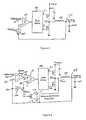
- FIG. 3diagrammatically illustrates the general architecture of a synthetic ripple regulator in accordance the present invention
- FIG. 4diagrammatically illustrates a non-limiting implementation of the synthetic ripple regulator of FIG. 3;
- FIG. 5is a timing diagram showing waveforms associated with the operation of the synthetic ripple regulator of FIGS. 3 and 4;
- FIG. 6shows the transconductance amplifier of FIG. 4 implemented as two independently controlled transconductance amplifiers.
- FIG. 3diagrammatically illustrates the general architecture of a synthetic ripple regulator in accordance the present invention.
- the synthetic ripple regulator according to the present inventioninjects an auxiliary ripple voltage (Ripple) into the feedback path to input 11 of hysteretic comparator 10 , so as to be combined with the output voltage at node 55 .
- This auxiliary waveformis to be synchronized to the switching intervals of the converter, and have a shape corresponding to that of the current waveform in the inductor which, in the present example, is a triangular wave shaped ripple current.
- Driving a capacitor with a current proportional to the voltage across the inductorprovides the desired waveform shape.
- the driving current I C to the capacitoris proportional to the ‘Input’ less the ‘Output’ and proportional to the ‘Output’ during the remaining Interval (T ⁇ t on ).
- FIG. 4A non-limiting implementation of generating such a ripple waveform for injection in the synthetic ripple regulator of FIG. 3 is diagrammatically illustrated in FIG. 4 as comprising a transconductance amplifier 110 coupled with a ‘ripple voltage’ capacitor 120 .
- the transconductance amplifier 110produces an output current I RAMP proportional to the voltage across the inductor 50 in accordance with equation (1).
- the ripple voltage capacitor 120transforms this current into an inductor current-representative voltage having the desired waveform shape.
- a benefit of synthesizing the ripple waveform based on inductor currentis the inherent feed-forward characteristic. For a step input voltage change, the current I RAMP will change proportionally to modify the conduction interval of the power switching devices.
- transconductance amplifier 110has a first, non-inverting (+) input 111 coupled to the phase node 35 at one end to inductor 50 , and a second ( ⁇ ) input 112 coupled to the output voltage node 55 at the other end of the inductor, so that the transconductance amplifier 10 ‘sees’ the voltage across the inductor.
- the output voltage node 55is further coupled to a first terminal 121 of capacitor 120 and to the inverting ( ⁇ ) input 131 of an error amplifier 130 inserted upstream of the hysteresis comparator 10 .
- the error amplifier 130serves to increase the DC regulation accuracy, providing high DC gain to reduce errors due to ripple wave shape, various offsets, and other errors.
- Error amplifier 130has a second, non-inverting (+) input 132 thereof coupled to receive the voltage Reference, while its output 133 is coupled to the non-inverting (+) input 12 of hysteresis comparator 10 .
- the output of the error amplifier 130follows the load current.
- the transconductance amplifier 110has its output coupled to a second terminal 122 of the capacitor 120 and to inverting ( ⁇ ) input 11 of the hysteresis comparator 10 .
- the operation of the synthetic ripple regulator of FIGS. 3 and 4may be understood with reference to the set of waveform timing diagrams of FIG. 5 .
- the inductance of inductor 50is 1 ⁇ H and the output capacitance is 10 ⁇ F.
- the line M 1(at the 30 ⁇ sec time mark) represents a change in input voltage from a value on the order of 3.6 VDC prior to M 1 to a value on the order of 4.2 VDC at M 1 and thereafter.
- the upper waveform 501corresponds to the ripple voltage generated across the ripple voltage capacitor 120 ; the middle waveform 502 is the current through inductor 50 , and the lower waveform 503 is the output voltage at node 55 .
- the converteris initially supplying an inductor current on the order 100 mA for an input supply voltage of 3.6 VDC. This inductor current is discontinuous and the switching frequency has a relatively stable value on the order of 900 kHz.
- stepwise (X 10 )increase in the load current from 100 mA to a value on the order of 1 A, and the switching frequency increases to a frequency on the order of 1.5 MHz.
- the amount of ripple 532 for this further transientis also relatively small (on the order of only +/ ⁇ 3 mV and dropping to +/ ⁇ 1.5 mV), so that the output voltage is effectively regulated at a value on the order of the voltage Reference of 1 VDC.
- the synthetic ripple regulator of the present inventionis effective to replicate the waveform ripple current through the output inductor, and use this auxiliary mirrored waveform to control toggling of the hysteretic comparator. Using such a reconstructed current for ripple regulation results in low output ripple, input voltage feed forward, and simplified compensation.
- a summing node with the ripple referenced to groundmay be used.
- the ramp currentcan be predetermined for applications that have fixed input and output voltage levels.
- the transconductance amplifiercan be connected to a gated input signal instead of the phase node.
- transconductance amplifier 110may be implemented as two independently controlled transconductance amplifiers, as shown at 150 and 160 in FIG. 6 .
- transconductance amplifier 150has its input coupled to the input node
- transconductance amplifier 160has its input coupled to output node 55 .
- the outputs of the amplifiersare selectively switched through an analog multiplexer 170 to capacitor 120 and the inverting ( ⁇ ) input 11 of hysteretic comparator 10 .
- This alternative configurationallows the ramp current to be more precisely controlled for improved linearity.
Landscapes
- Engineering & Computer Science (AREA)
- Power Engineering (AREA)
- Dc-Dc Converters (AREA)
- Soil Working Implements (AREA)
- Tone Control, Compression And Expansion, Limiting Amplitude (AREA)
- Supply And Distribution Of Alternating Current (AREA)
Abstract
Description

Claims (4)
Priority Applications (13)
| Application Number | Priority Date | Filing Date | Title |
|---|---|---|---|
| US10/236,787US6791306B2 (en) | 2002-01-29 | 2002-09-06 | Synthetic ripple regulator |
| DE60209768TDE60209768D1 (en) | 2002-01-29 | 2002-09-11 | REGULATOR BASED ON SYNTHETIC HARMONICS |
| JP2003565026AJP3981083B2 (en) | 2002-01-29 | 2002-09-11 | Synthetic ripple regulator |
| PCT/US2002/028956WO2003065558A2 (en) | 2002-01-29 | 2002-09-11 | Synthetic ripple regulator |
| CNB028286766ACN100454738C (en) | 2002-01-29 | 2002-09-11 | Synthetic Ripple Regulator |
| EP02775795AEP1472777B1 (en) | 2002-01-29 | 2002-09-11 | Synthetic ripple regulator |
| AT02775795TATE320105T1 (en) | 2002-01-29 | 2002-09-11 | CONTROLLER BASED ON SYNTHETIC HARMONICS |
| KR1020047011498AKR100614841B1 (en) | 2002-01-29 | 2002-09-11 | Composite ripple regulator |
| TW091120997ATW578360B (en) | 2002-01-29 | 2002-09-13 | Synthetic ripple regulator |
| US10/673,684US6922044B2 (en) | 2002-09-06 | 2003-09-29 | Synchronization of multiphase synthetic ripple voltage regulator |
| US10/853,733US7132820B2 (en) | 2002-09-06 | 2004-05-25 | Synthetic ripple regulator |
| US10/853,022US7019502B2 (en) | 2002-09-06 | 2004-05-25 | Synchronization of multiphase synthetic ripple voltage regulator |
| US12/255,346USRE43414E1 (en) | 2002-09-06 | 2008-10-21 | Synthetic ripple regulator |
Applications Claiming Priority (2)
| Application Number | Priority Date | Filing Date | Title |
|---|---|---|---|
| US35268302P | 2002-01-29 | 2002-01-29 | |
| US10/236,787US6791306B2 (en) | 2002-01-29 | 2002-09-06 | Synthetic ripple regulator |
Related Child Applications (2)
| Application Number | Title | Priority Date | Filing Date |
|---|---|---|---|
| US10/673,684Continuation-In-PartUS6922044B2 (en) | 2002-09-06 | 2003-09-29 | Synchronization of multiphase synthetic ripple voltage regulator |
| US10/853,733Continuation-In-PartUS7132820B2 (en) | 2002-09-06 | 2004-05-25 | Synthetic ripple regulator |
Publications (2)
| Publication Number | Publication Date |
|---|---|
| US20030142519A1 US20030142519A1 (en) | 2003-07-31 |
| US6791306B2true US6791306B2 (en) | 2004-09-14 |
Family
ID=27616390
Family Applications (1)
| Application Number | Title | Priority Date | Filing Date |
|---|---|---|---|
| US10/236,787Expired - LifetimeUS6791306B2 (en) | 2002-01-29 | 2002-09-06 | Synthetic ripple regulator |
Country Status (9)
| Country | Link |
|---|---|
| US (1) | US6791306B2 (en) |
| EP (1) | EP1472777B1 (en) |
| JP (1) | JP3981083B2 (en) |
| KR (1) | KR100614841B1 (en) |
| CN (1) | CN100454738C (en) |
| AT (1) | ATE320105T1 (en) |
| DE (1) | DE60209768D1 (en) |
| TW (1) | TW578360B (en) |
| WO (1) | WO2003065558A2 (en) |
Cited By (53)
| Publication number | Priority date | Publication date | Assignee | Title |
|---|---|---|---|---|
| US20040056644A1 (en)* | 2002-09-20 | 2004-03-25 | Hung-I Wang | Current sense apparatus and method using a combination of a simulation and a real sense for a switching mode power converter |
| US20040080303A1 (en)* | 2002-07-24 | 2004-04-29 | Seiko Epson Corporation | Power supply circuit |
| US20040104772A1 (en)* | 2002-08-30 | 2004-06-03 | Stmicroelectronics S.R.L | Transconductance amplifier for inductive loads and method for driving inductive loads |
| US20040135563A1 (en)* | 2002-10-25 | 2004-07-15 | International Rectifier Corporation | Fixed frequency hysteretic regulator |
| US20040193671A1 (en)* | 2002-12-20 | 2004-09-30 | Adrian Stoica | System for implementation of transforms |
| US20040232901A1 (en)* | 2003-05-19 | 2004-11-25 | Kent Huang | Delta-sigma DC-to-DC converter and method thereof |
| US20050007089A1 (en)* | 2003-07-08 | 2005-01-13 | Rohm Co., Ltd. | Step-up/step-down DC-DC converter and portable device employing it |
| US20050190128A1 (en)* | 2004-02-05 | 2005-09-01 | Tohoku Pioneer Corporation | Drive device and drive method of light emitting display panel |
| US20060038238A1 (en)* | 2004-08-23 | 2006-02-23 | Lotfi Ashraf W | Integrated circuit incorporating higher voltage devices and low voltage devices therein |
| US20060043952A1 (en)* | 2004-08-27 | 2006-03-02 | Kent Huang | Spring modulation with fast load-transient response for a voltage regulator |
| US20060044174A1 (en)* | 2004-07-30 | 2006-03-02 | Erich Bayer | Hysteretic DC/DC converter |
| US20060055385A1 (en)* | 2004-09-14 | 2006-03-16 | Entire Interest | Switching power supply control |
| US20060071694A1 (en)* | 2004-10-06 | 2006-04-06 | Maclean Kenneth G | Versatile system for output energy limiting circuitry |
| US7145317B1 (en)* | 2004-12-13 | 2006-12-05 | Intersil Americas Inc. | Constant frequency duty cycle independent synthetic ripple regulator |
| US20060284608A1 (en)* | 2002-11-12 | 2006-12-21 | O2Micro International Limited | Controller for DC to DC Converter |
| US20070165427A1 (en)* | 2006-01-13 | 2007-07-19 | Dell Products L.P. | Error voltage ripple compensation to extend bandwidth of a feedback loop in a DC-to-DC converter |
| US20070176587A1 (en)* | 2002-11-12 | 2007-08-02 | O2Micro International Limited | Controller for DC to DC Converter |
| US20070222395A1 (en)* | 2006-03-22 | 2007-09-27 | Ming-Hsueh Chen | Switching Regulator for Fixing a Frequency |
| US20070247129A1 (en)* | 2006-04-20 | 2007-10-25 | Jacobs Mark E | Optimal feedback control of switch-mode power converters |
| US20080101102A1 (en)* | 2006-10-25 | 2008-05-01 | Laszlo Lipcsei | Circuits and methods for controlling a converter |
| US20080157736A1 (en)* | 2006-05-31 | 2008-07-03 | Stmicroelectronics S.R.L. | Controller for dc-dc converters with bypass compensation |
| US20080224681A1 (en)* | 2002-11-12 | 2008-09-18 | O2Micro, Inc. | Controller for a DC to DC Converter |
| US20090033293A1 (en)* | 2007-08-01 | 2009-02-05 | Intersil Americas Inc. | Voltage converter with combined capacitive voltage divider, buck converter and battery charger |
| US20090309633A1 (en)* | 2008-06-17 | 2009-12-17 | Monolithic Power Systems | Charge pump for switched capacitor circuits with slew-rate control of in-rush current |
| US20100033153A1 (en)* | 2008-08-05 | 2010-02-11 | Intersil Americas Inc. | Pwm clock generation system and method to improve transient response of a voltage regulator |
| US20100327836A1 (en)* | 2008-03-24 | 2010-12-30 | Gang Li | Controllers for dc to dc converters |
| US20110080150A1 (en)* | 2008-01-25 | 2011-04-07 | Pacific Tech Microelectronics | Systems and Methods for DC to DC Conversion with Current Mode Control |
| US20110121806A1 (en)* | 2009-11-24 | 2011-05-26 | James Garrett | Regulator including hysteretic control |
| US8018212B1 (en) | 2007-08-24 | 2011-09-13 | Intersil Americas Inc. | Buck-boost regulator |
| US8018215B1 (en)* | 2008-06-26 | 2011-09-13 | National Semiconductor Corporation | Apparatus and method for monitoring the inductance value of a switching regulator |
| US20120025793A1 (en)* | 2010-07-29 | 2012-02-02 | Richtek Technology Corp. | Offset and delay cancellation circuit for a switching dc-dc power supply |
| US20120038340A1 (en)* | 2010-08-16 | 2012-02-16 | Taiwan Semiconductor Manufacturing Company, Ltd. | Dynamic control loop for switching regulators |
| US8138739B1 (en) | 2008-10-03 | 2012-03-20 | Fairchild Semiconductor Corporation | Circuits and methods for improving transient response of hysteretic DC-DC converters |
| US8427113B2 (en) | 2007-08-01 | 2013-04-23 | Intersil Americas LLC | Voltage converter with combined buck converter and capacitive voltage divider |
| WO2013063021A2 (en) | 2011-10-26 | 2013-05-02 | Microsemi Corporation | Converter with hysteretic control |
| US8446135B2 (en)* | 2011-02-24 | 2013-05-21 | Richtek Technology Corp. | Control circuit and method for a ripple regulator system |
| US20130146034A1 (en)* | 2010-01-22 | 2013-06-13 | Continental Automotive Systems, Inc. | Switch-Mode Synthetic Power Inductor |
| US8476886B1 (en) | 2008-05-27 | 2013-07-02 | Fairchild Semiconductor Corporation | Differential hysteretic DC-DC converter |
| US8692535B1 (en)* | 2010-12-09 | 2014-04-08 | International Rectifier Corporation | Control parameter adjustment in a discontinuous power mode |
| US8786270B2 (en) | 2010-11-08 | 2014-07-22 | Intersil Americas Inc. | Synthetic ripple regulator with frequency control |
| US20140225578A1 (en)* | 2013-02-08 | 2014-08-14 | Excelliance Mos Corporation | Voltage converter |
| US20150123631A1 (en)* | 2013-11-07 | 2015-05-07 | Silergy Semiconductor Technology (Hangzhou) Ltd | Over voltage protection control method and circuit for four-switch buck-boost converter |
| US9071125B2 (en) | 2012-02-09 | 2015-06-30 | Ricoh Electronic Devices Co., Ltd. | Switching regulator, control method thereof and power-supply device |
| US20160062375A1 (en)* | 2014-08-27 | 2016-03-03 | Intersil Americans Llc | Current mode control modulator with combined control signals and improved dynamic range |
| US9293988B2 (en) | 2012-12-11 | 2016-03-22 | Samsung Electronics Co., Ltd. | Current mode PWM boost converter with frequency dithering |
| US9467044B2 (en) | 2013-05-16 | 2016-10-11 | Upi Semiconductor Corp. | Timing generator and timing signal generation method for power converter |
| US9812962B2 (en) | 2015-09-30 | 2017-11-07 | Intersil Americas LLC | Method and system for increasing efficiency and controlling slew rate in DC-DC converters |
| US10110127B2 (en) | 2015-12-04 | 2018-10-23 | Intersil Americas LLC | Method and system for DC-DC voltage converters |
| US10326354B2 (en) | 2015-12-14 | 2019-06-18 | Intersil Americas LLC | Method and system for DC-DC voltage converters with diminished PWM jitter |
| US10469778B2 (en)* | 2017-10-27 | 2019-11-05 | Semiconductor Components Industries, Llc | Methods and apparatus for actuator control |
| US10637351B2 (en) | 2016-07-25 | 2020-04-28 | Taiwan Semiconductor Manufacturing Co., Ltd. | Regulated voltage systems and methods using intrinsically varied process characteristics |
| US10742120B1 (en) | 2019-01-21 | 2020-08-11 | Dialog Semiconductor (Uk) Limited | Pulse frequency modulation control of a power converter |
| US20210399635A1 (en)* | 2020-06-18 | 2021-12-23 | Upi Semiconductor Corp. | Control circuit and control method of power converter |
Families Citing this family (36)
| Publication number | Priority date | Publication date | Assignee | Title |
|---|---|---|---|---|
| US7019502B2 (en)* | 2002-09-06 | 2006-03-28 | Intersil America's Inc. | Synchronization of multiphase synthetic ripple voltage regulator |
| US6922044B2 (en)* | 2002-09-06 | 2005-07-26 | Intersil Americas Inc. | Synchronization of multiphase synthetic ripple voltage regulator |
| US6906499B2 (en) | 2003-06-27 | 2005-06-14 | Seagate Technology Llc | Current mode bang-bang controller in a switching voltage regulator |
| US7005924B2 (en)* | 2004-02-19 | 2006-02-28 | Intersil Americas Inc. | Current limiting circuit with rapid response feedback loop |
| US20050237037A1 (en)* | 2004-04-23 | 2005-10-27 | Intersil Americas Inc. | Switching power supply controller system and method |
| US8378527B2 (en)* | 2004-06-02 | 2013-02-19 | Research In Motion Limited | Universal serial bus current limit |
| US7764057B2 (en)* | 2004-06-25 | 2010-07-27 | Intersil Americas Inc. | Constant-on-time switching power supply with virtual ripple feedback and related system and method |
| US7439721B2 (en)* | 2005-06-03 | 2008-10-21 | Intersil Americas Inc. | Constant-on-time power-supply controller and related system and method |
| US8350551B2 (en)* | 2005-06-03 | 2013-01-08 | Intersil Americas LLC | Power-supply controller |
| EP1920524A2 (en)* | 2005-08-24 | 2008-05-14 | Nxp B.V. | Linear transconductor for a one-cycle controller, notably for a dc-dc switching converter |
| US7457140B2 (en)* | 2006-08-18 | 2008-11-25 | Fairchild Semiconductor Corporation | Power converter with hysteretic control |
| US7482793B2 (en)* | 2006-09-11 | 2009-01-27 | Micrel, Inc. | Ripple generation in buck regulator using fixed on-time control to enable the use of output capacitor having any ESR |
| US8174250B2 (en)* | 2007-10-04 | 2012-05-08 | International Rectifier Corporation | Fixed frequency ripple regulator |
| US8154268B2 (en)* | 2007-12-03 | 2012-04-10 | Intersil Americas Inc. | Switching regulator with balanced control configuration with filtering and referencing to eliminate compensation |
| JP4613986B2 (en)* | 2008-07-28 | 2011-01-19 | 日本テキサス・インスツルメンツ株式会社 | Switching power supply |
| EP2234255A1 (en)* | 2009-03-27 | 2010-09-29 | Diodes Zetex Semiconductors Limited | Controller for switching regulator, switching regulator and light source |
| CN101997410B (en)* | 2009-08-20 | 2012-10-10 | 立锜科技股份有限公司 | Switching power supply circuit with instantaneous control function and its control circuit and method |
| EP2333635A1 (en)* | 2009-12-14 | 2011-06-15 | Mitsubishi Electric R&D Centre Europe B.V. | Method for obtaining information enabling the determination of a characteristic of a power source |
| US8405368B2 (en)* | 2010-03-26 | 2013-03-26 | Intersil Americas Inc. | Multiple phase switching regulator with phase current sharing |
| JP5131321B2 (en)* | 2010-07-01 | 2013-01-30 | 日本テキサス・インスツルメンツ株式会社 | Switching power supply |
| CN102386771B (en)* | 2010-09-02 | 2014-10-01 | 凹凸电子(武汉)有限公司 | Controller, current control method and DC-DC converter |
| TWI465148B (en)* | 2011-03-17 | 2014-12-11 | Green Solution Tech Co Ltd | Led driving circuit and led driving controller |
| JP5768475B2 (en)* | 2011-04-28 | 2015-08-26 | ミツミ電機株式会社 | Switching power supply |
| CN102316644B (en)* | 2011-09-05 | 2014-01-15 | 泉芯电子技术(深圳)有限公司 | High precision LED constant current drive unit |
| CN103378726B (en)* | 2012-04-18 | 2015-08-19 | 立锜科技股份有限公司 | Switching power supply and its control circuit and control method |
| CN104009628B (en)* | 2013-02-22 | 2016-12-28 | 杰力科技股份有限公司 | Voltage converter |
| KR101508428B1 (en) | 2013-08-05 | 2015-04-07 | 인하대학교 산학협력단 | To Output Ripple Voltage Control the Hysteretic Buck Converter Using Thermister |
| CN104427702B (en)* | 2013-09-04 | 2018-04-27 | 深圳市海洋王照明工程有限公司 | Ripple compensation circuit, BUCK types LED driver and lamps and lanterns |
| US9912229B2 (en)* | 2013-12-31 | 2018-03-06 | Texas Instruments Incorporated | Multiple output integrated power factor correction |
| CN104124870B (en)* | 2014-08-08 | 2017-09-05 | 华为技术有限公司 | switching power supply |
| TWI551018B (en)* | 2015-12-15 | 2016-09-21 | Nat Inst Chung Shan Science & Technology | Power factor correction conversion device and control method thereof |
| CN106199426B (en)* | 2016-07-01 | 2019-06-21 | 贵阳华旭科技开发有限公司 | Direct current generator ripple fictitious load |
| US10168726B2 (en)* | 2016-11-16 | 2019-01-01 | Anpec Electronics Corporation | Self-adaptive startup compensation device |
| CN111130346B (en)* | 2018-11-01 | 2020-11-20 | 财团法人成大研究发展基金会 | DC Converter and Digital Fixed On-Time Controller |
| CN112311364A (en)* | 2019-08-01 | 2021-02-02 | 南昌工学院 | SPMW control method for single-phase low-current harmonic wave |
| US12374982B2 (en)* | 2023-03-31 | 2025-07-29 | Novatek Microelectronics Corp. | Feedback control device and feedback control method for DC-to-DC converter |
Citations (13)
| Publication number | Priority date | Publication date | Assignee | Title |
|---|---|---|---|---|
| US4413224A (en) | 1979-04-30 | 1983-11-01 | Yaakov Krupka | Micropower system |
| DE3343883A1 (en) | 1982-12-08 | 1984-06-14 | Fuji Electric Co Ltd | Method and device for two-point control of a load current |
| US4521726A (en) | 1981-11-17 | 1985-06-04 | Motorola, Inc. | Control circuitry for a pulse-width-modulated switching power supply |
| US4658204A (en) | 1986-02-07 | 1987-04-14 | Prime Computer, Inc. | Anticipatory power failure detection apparatus and method |
| FR2610149A1 (en) | 1987-01-22 | 1988-07-29 | Telecommunications Sa | DC/DC converter with high efficiency and small load |
| DE4206478A1 (en) | 1992-03-02 | 1993-09-09 | Thomson Brandt Gmbh | Voltage stabiliser integrated circuit for CD player, television receiver or video recorder - compares constant voltage provided by internal source with reference voltage and clock voltage to control series switch, with rectifier across IC pins |
| US5399958A (en) | 1993-05-31 | 1995-03-21 | Nec Corporation | Switching power supply circuit having a reduced ripple voltage |
| EP0650250A1 (en) | 1993-10-22 | 1995-04-26 | STMicroelectronics S.r.l. | DC-to-DC converter operating in a discontinuous mode |
| EP0883051A1 (en) | 1997-06-04 | 1998-12-09 | STMicroelectronics S.A. | System for supplying a regulated voltage |
| US6147478A (en)* | 1999-09-17 | 2000-11-14 | Texas Instruments Incorporated | Hysteretic regulator and control method having switching frequency independent from output filter |
| EP1073187A2 (en) | 1999-07-26 | 2001-01-31 | Nec Corporation | Switching regulator |
| US6433525B2 (en)* | 2000-05-03 | 2002-08-13 | Intersil Americas Inc. | Dc to DC converter method and circuitry |
| US6583610B2 (en)* | 2001-03-12 | 2003-06-24 | Semtech Corporation | Virtual ripple generation in switch-mode power supplies |
Family Cites Families (2)
| Publication number | Priority date | Publication date | Assignee | Title |
|---|---|---|---|---|
| US5770940A (en)* | 1995-08-09 | 1998-06-23 | Switch Power, Inc. | Switching regulator |
| JP3389524B2 (en)* | 1999-02-23 | 2003-03-24 | 松下電器産業株式会社 | Switching regulator, DC / DC converter, and LSI system with switching regulator |
- 2002
- 2002-09-06USUS10/236,787patent/US6791306B2/ennot_activeExpired - Lifetime
- 2002-09-11JPJP2003565026Apatent/JP3981083B2/ennot_activeExpired - Fee Related
- 2002-09-11KRKR1020047011498Apatent/KR100614841B1/ennot_activeExpired - Lifetime
- 2002-09-11EPEP02775795Apatent/EP1472777B1/ennot_activeExpired - Lifetime
- 2002-09-11CNCNB028286766Apatent/CN100454738C/ennot_activeExpired - Lifetime
- 2002-09-11DEDE60209768Tpatent/DE60209768D1/ennot_activeExpired - Lifetime
- 2002-09-11ATAT02775795Tpatent/ATE320105T1/ennot_activeIP Right Cessation
- 2002-09-11WOPCT/US2002/028956patent/WO2003065558A2/enactiveIP Right Grant
- 2002-09-13TWTW091120997Apatent/TW578360B/ennot_activeIP Right Cessation
Patent Citations (13)
| Publication number | Priority date | Publication date | Assignee | Title |
|---|---|---|---|---|
| US4413224A (en) | 1979-04-30 | 1983-11-01 | Yaakov Krupka | Micropower system |
| US4521726A (en) | 1981-11-17 | 1985-06-04 | Motorola, Inc. | Control circuitry for a pulse-width-modulated switching power supply |
| DE3343883A1 (en) | 1982-12-08 | 1984-06-14 | Fuji Electric Co Ltd | Method and device for two-point control of a load current |
| US4658204A (en) | 1986-02-07 | 1987-04-14 | Prime Computer, Inc. | Anticipatory power failure detection apparatus and method |
| FR2610149A1 (en) | 1987-01-22 | 1988-07-29 | Telecommunications Sa | DC/DC converter with high efficiency and small load |
| DE4206478A1 (en) | 1992-03-02 | 1993-09-09 | Thomson Brandt Gmbh | Voltage stabiliser integrated circuit for CD player, television receiver or video recorder - compares constant voltage provided by internal source with reference voltage and clock voltage to control series switch, with rectifier across IC pins |
| US5399958A (en) | 1993-05-31 | 1995-03-21 | Nec Corporation | Switching power supply circuit having a reduced ripple voltage |
| EP0650250A1 (en) | 1993-10-22 | 1995-04-26 | STMicroelectronics S.r.l. | DC-to-DC converter operating in a discontinuous mode |
| EP0883051A1 (en) | 1997-06-04 | 1998-12-09 | STMicroelectronics S.A. | System for supplying a regulated voltage |
| EP1073187A2 (en) | 1999-07-26 | 2001-01-31 | Nec Corporation | Switching regulator |
| US6147478A (en)* | 1999-09-17 | 2000-11-14 | Texas Instruments Incorporated | Hysteretic regulator and control method having switching frequency independent from output filter |
| US6433525B2 (en)* | 2000-05-03 | 2002-08-13 | Intersil Americas Inc. | Dc to DC converter method and circuitry |
| US6583610B2 (en)* | 2001-03-12 | 2003-06-24 | Semtech Corporation | Virtual ripple generation in switch-mode power supplies |
Cited By (93)
| Publication number | Priority date | Publication date | Assignee | Title |
|---|---|---|---|---|
| US6998824B2 (en)* | 2002-07-24 | 2006-02-14 | Seiko Epson Corporation | Power supply circuit having a DC-DC conversion circuit and an intermediate node potential detection circuit |
| US20040080303A1 (en)* | 2002-07-24 | 2004-04-29 | Seiko Epson Corporation | Power supply circuit |
| US20040104772A1 (en)* | 2002-08-30 | 2004-06-03 | Stmicroelectronics S.R.L | Transconductance amplifier for inductive loads and method for driving inductive loads |
| US6919763B2 (en)* | 2002-08-30 | 2005-07-19 | Stmicroelectronics S.R.L. | Transconductance amplifier for inductive loads and method for driving inductive loads |
| US6930474B2 (en)* | 2002-09-20 | 2005-08-16 | Richtek Technology Corp. | Current sense apparatus and method using a combination of a simulation and a real sense for a switching mode power converter |
| US20040056644A1 (en)* | 2002-09-20 | 2004-03-25 | Hung-I Wang | Current sense apparatus and method using a combination of a simulation and a real sense for a switching mode power converter |
| US20040135563A1 (en)* | 2002-10-25 | 2004-07-15 | International Rectifier Corporation | Fixed frequency hysteretic regulator |
| US6885175B2 (en)* | 2002-10-25 | 2005-04-26 | International Rectifier Corporation | Fixed frequency hysteretic regulator |
| US20060284608A1 (en)* | 2002-11-12 | 2006-12-21 | O2Micro International Limited | Controller for DC to DC Converter |
| US20070176587A1 (en)* | 2002-11-12 | 2007-08-02 | O2Micro International Limited | Controller for DC to DC Converter |
| US20080224681A1 (en)* | 2002-11-12 | 2008-09-18 | O2Micro, Inc. | Controller for a DC to DC Converter |
| US7598718B2 (en) | 2002-11-12 | 2009-10-06 | O2Micro International Limited | Controller for DC to DC converter |
| US20040193671A1 (en)* | 2002-12-20 | 2004-09-30 | Adrian Stoica | System for implementation of transforms |
| US6946823B2 (en)* | 2003-05-19 | 2005-09-20 | Richtek Technology Corp. | Delta-sigma DC-to-DC converter and method thereof |
| US20040232901A1 (en)* | 2003-05-19 | 2004-11-25 | Kent Huang | Delta-sigma DC-to-DC converter and method thereof |
| US6958595B2 (en)* | 2003-07-08 | 2005-10-25 | Rohm Co., Ltd. | Step-up/step-down DC-DC converter and portable device employing it |
| US20050007089A1 (en)* | 2003-07-08 | 2005-01-13 | Rohm Co., Ltd. | Step-up/step-down DC-DC converter and portable device employing it |
| US20050190128A1 (en)* | 2004-02-05 | 2005-09-01 | Tohoku Pioneer Corporation | Drive device and drive method of light emitting display panel |
| US7515146B2 (en)* | 2004-02-05 | 2009-04-07 | Tohoku Pioneer Corporation | Drive device and drive method of light emitting display panel |
| US20060044174A1 (en)* | 2004-07-30 | 2006-03-02 | Erich Bayer | Hysteretic DC/DC converter |
| US7420357B2 (en)* | 2004-07-30 | 2008-09-02 | Texas Instruments Deutschland Gmbh | Hysteretic DC/DC converter |
| US20060038238A1 (en)* | 2004-08-23 | 2006-02-23 | Lotfi Ashraf W | Integrated circuit incorporating higher voltage devices and low voltage devices therein |
| US20060043952A1 (en)* | 2004-08-27 | 2006-03-02 | Kent Huang | Spring modulation with fast load-transient response for a voltage regulator |
| US7274182B2 (en)* | 2004-08-27 | 2007-09-25 | Richtek Technology Corp. | Spring modulation with fast load-transient response for a voltage regulator |
| US7741824B2 (en)* | 2004-09-14 | 2010-06-22 | Semiconductor Components Industries, Llc | Switching power supply control |
| US7595617B2 (en) | 2004-09-14 | 2009-09-29 | Semiconductor Components Industries, L.L.C. | Switching power supply control |
| US20090237060A1 (en)* | 2004-09-14 | 2009-09-24 | Schiff Tod F | Switching power supply control |
| US20060055385A1 (en)* | 2004-09-14 | 2006-03-16 | Entire Interest | Switching power supply control |
| US7034583B1 (en)* | 2004-10-06 | 2006-04-25 | Texas Instruments Incorporated | Versatile system for output energy limiting circuitry |
| US20060071694A1 (en)* | 2004-10-06 | 2006-04-06 | Maclean Kenneth G | Versatile system for output energy limiting circuitry |
| US7145317B1 (en)* | 2004-12-13 | 2006-12-05 | Intersil Americas Inc. | Constant frequency duty cycle independent synthetic ripple regulator |
| US20070165427A1 (en)* | 2006-01-13 | 2007-07-19 | Dell Products L.P. | Error voltage ripple compensation to extend bandwidth of a feedback loop in a DC-to-DC converter |
| US7538535B2 (en) | 2006-01-13 | 2009-05-26 | Dell Products L.P. | Error voltage ripple compensation to extend bandwidth of a feedback loop in a DC-to-DC converter |
| US7508180B2 (en) | 2006-03-22 | 2009-03-24 | Anpec Electronics Corporation | Switching regulator for fixing a frequency |
| US20070222395A1 (en)* | 2006-03-22 | 2007-09-27 | Ming-Hsueh Chen | Switching Regulator for Fixing a Frequency |
| US7459893B2 (en) | 2006-04-20 | 2008-12-02 | Mark E Jacobs | Optimal feedback control of switch-mode power converters |
| US20070247129A1 (en)* | 2006-04-20 | 2007-10-25 | Jacobs Mark E | Optimal feedback control of switch-mode power converters |
| US20080157736A1 (en)* | 2006-05-31 | 2008-07-03 | Stmicroelectronics S.R.L. | Controller for dc-dc converters with bypass compensation |
| US7960956B2 (en)* | 2006-05-31 | 2011-06-14 | Stmicroelectronics S.R.L. | Controller for DC-DC converters with bypass compensation |
| US20080101102A1 (en)* | 2006-10-25 | 2008-05-01 | Laszlo Lipcsei | Circuits and methods for controlling a converter |
| US7816896B2 (en) | 2006-10-25 | 2010-10-19 | 02Micro International Limited | Circuits and methods for controlling a converter |
| US20090033293A1 (en)* | 2007-08-01 | 2009-02-05 | Intersil Americas Inc. | Voltage converter with combined capacitive voltage divider, buck converter and battery charger |
| US8427113B2 (en) | 2007-08-01 | 2013-04-23 | Intersil Americas LLC | Voltage converter with combined buck converter and capacitive voltage divider |
| US8018212B1 (en) | 2007-08-24 | 2011-09-13 | Intersil Americas Inc. | Buck-boost regulator |
| US8085011B1 (en) | 2007-08-24 | 2011-12-27 | Intersil Americas Inc. | Boost regulator using synthetic ripple regulation |
| US20110080150A1 (en)* | 2008-01-25 | 2011-04-07 | Pacific Tech Microelectronics | Systems and Methods for DC to DC Conversion with Current Mode Control |
| US8536849B2 (en)* | 2008-01-25 | 2013-09-17 | Diodes Incorporated | Systems and methods for DC to DC conversion with peak and valley current detection control |
| US9059632B2 (en) | 2008-03-24 | 2015-06-16 | O2Micro, Inc. | Controllers for DC to DC converters |
| US20100327836A1 (en)* | 2008-03-24 | 2010-12-30 | Gang Li | Controllers for dc to dc converters |
| US8476886B1 (en) | 2008-05-27 | 2013-07-02 | Fairchild Semiconductor Corporation | Differential hysteretic DC-DC converter |
| US8049551B2 (en)* | 2008-06-17 | 2011-11-01 | Monolithic Power Systems, Inc. | Charge pump for switched capacitor circuits with slew-rate control of in-rush current |
| US20090309633A1 (en)* | 2008-06-17 | 2009-12-17 | Monolithic Power Systems | Charge pump for switched capacitor circuits with slew-rate control of in-rush current |
| US8018215B1 (en)* | 2008-06-26 | 2011-09-13 | National Semiconductor Corporation | Apparatus and method for monitoring the inductance value of a switching regulator |
| US20100033153A1 (en)* | 2008-08-05 | 2010-02-11 | Intersil Americas Inc. | Pwm clock generation system and method to improve transient response of a voltage regulator |
| US8148967B2 (en) | 2008-08-05 | 2012-04-03 | Intersil Americas Inc. | PWM clock generation system and method to improve transient response of a voltage regulator |
| US8138739B1 (en) | 2008-10-03 | 2012-03-20 | Fairchild Semiconductor Corporation | Circuits and methods for improving transient response of hysteretic DC-DC converters |
| US8618779B2 (en) | 2009-11-24 | 2013-12-31 | Fairchild Semiconductor Corporation | Switch-mode regulator including hysteretic control |
| US20110121806A1 (en)* | 2009-11-24 | 2011-05-26 | James Garrett | Regulator including hysteretic control |
| US20130146034A1 (en)* | 2010-01-22 | 2013-06-13 | Continental Automotive Systems, Inc. | Switch-Mode Synthetic Power Inductor |
| US8789516B2 (en)* | 2010-01-22 | 2014-07-29 | Continental Automotive Systems, Inc. | Switch-mode synthetic power inductor |
| US20120025793A1 (en)* | 2010-07-29 | 2012-02-02 | Richtek Technology Corp. | Offset and delay cancellation circuit for a switching dc-dc power supply |
| US8791678B2 (en)* | 2010-07-29 | 2014-07-29 | Richtek Technology Corp. | Offset and delay cancellation circuit for a switching DC-DC power supply |
| US8450990B2 (en)* | 2010-08-16 | 2013-05-28 | Taiwan Semiconductor Manufacturing Company, Ltd. | Dynamic control loop for switching regulators |
| US9825524B2 (en) | 2010-08-16 | 2017-11-21 | Taiwan Semiconductor Manufacturing Company, Ltd. | Dynamic control loop for switching regulators |
| US20120038340A1 (en)* | 2010-08-16 | 2012-02-16 | Taiwan Semiconductor Manufacturing Company, Ltd. | Dynamic control loop for switching regulators |
| US8786270B2 (en) | 2010-11-08 | 2014-07-22 | Intersil Americas Inc. | Synthetic ripple regulator with frequency control |
| US8692535B1 (en)* | 2010-12-09 | 2014-04-08 | International Rectifier Corporation | Control parameter adjustment in a discontinuous power mode |
| US8446135B2 (en)* | 2011-02-24 | 2013-05-21 | Richtek Technology Corp. | Control circuit and method for a ripple regulator system |
| US8988056B2 (en) | 2011-10-26 | 2015-03-24 | Microsemi Corporation | Converter with hysteretic control |
| WO2013063021A2 (en) | 2011-10-26 | 2013-05-02 | Microsemi Corporation | Converter with hysteretic control |
| US9071125B2 (en) | 2012-02-09 | 2015-06-30 | Ricoh Electronic Devices Co., Ltd. | Switching regulator, control method thereof and power-supply device |
| US9293988B2 (en) | 2012-12-11 | 2016-03-22 | Samsung Electronics Co., Ltd. | Current mode PWM boost converter with frequency dithering |
| US20140225578A1 (en)* | 2013-02-08 | 2014-08-14 | Excelliance Mos Corporation | Voltage converter |
| US9134738B2 (en)* | 2013-02-08 | 2015-09-15 | Excelliance Mos Corporation | Voltage converter |
| US9467044B2 (en) | 2013-05-16 | 2016-10-11 | Upi Semiconductor Corp. | Timing generator and timing signal generation method for power converter |
| US20150123631A1 (en)* | 2013-11-07 | 2015-05-07 | Silergy Semiconductor Technology (Hangzhou) Ltd | Over voltage protection control method and circuit for four-switch buck-boost converter |
| US10003263B2 (en) | 2013-11-07 | 2018-06-19 | Silergy Semiconductor Technology (Hangzhou) Ltd | Over voltage protection control method and circuit for four-switch buck-boost converter |
| US9543822B2 (en)* | 2013-11-07 | 2017-01-10 | Silergy Semiconductor Technology (Hangzhou) Ltd | Over voltage protection control method and circuit for four-switch buck-boost converter |
| US9342086B2 (en)* | 2014-08-27 | 2016-05-17 | Intersil Americas LLC | Current mode control modulator with combined control signals and improved dynamic range |
| US20160062375A1 (en)* | 2014-08-27 | 2016-03-03 | Intersil Americans Llc | Current mode control modulator with combined control signals and improved dynamic range |
| US9812962B2 (en) | 2015-09-30 | 2017-11-07 | Intersil Americas LLC | Method and system for increasing efficiency and controlling slew rate in DC-DC converters |
| US10326365B2 (en) | 2015-09-30 | 2019-06-18 | Intersil Americas LLC | Method and system for increasing efficiency and controlling slew rate in DC-DC converters |
| US10110127B2 (en) | 2015-12-04 | 2018-10-23 | Intersil Americas LLC | Method and system for DC-DC voltage converters |
| US10700606B2 (en) | 2015-12-04 | 2020-06-30 | Intersil Americas LLC | Method and system controlling DC-DC voltage converters using tracking signal |
| US10326354B2 (en) | 2015-12-14 | 2019-06-18 | Intersil Americas LLC | Method and system for DC-DC voltage converters with diminished PWM jitter |
| US10637351B2 (en) | 2016-07-25 | 2020-04-28 | Taiwan Semiconductor Manufacturing Co., Ltd. | Regulated voltage systems and methods using intrinsically varied process characteristics |
| US11239749B2 (en) | 2016-07-25 | 2022-02-01 | Taiwan Semiconductor Manufacturing Co., Ltd. | Regulated voltage systems and methods using intrinsically varied process characteristics |
| US11606027B2 (en) | 2016-07-25 | 2023-03-14 | Taiwan Semiconductor Manufacturing Co., Ltd. | Regulated voltage systems and methods using intrinsically varied process characteristics |
| US11909312B2 (en) | 2016-07-25 | 2024-02-20 | Taiwan Semiconductor Manufacturing Co., Ltd. | Regulated voltage systems and methods using intrinsically varied process characteristics |
| US10469778B2 (en)* | 2017-10-27 | 2019-11-05 | Semiconductor Components Industries, Llc | Methods and apparatus for actuator control |
| US10742120B1 (en) | 2019-01-21 | 2020-08-11 | Dialog Semiconductor (Uk) Limited | Pulse frequency modulation control of a power converter |
| US20210399635A1 (en)* | 2020-06-18 | 2021-12-23 | Upi Semiconductor Corp. | Control circuit and control method of power converter |
| US11502601B2 (en)* | 2020-06-18 | 2022-11-15 | Upi Semiconductor Corp. | Control circuit and control method of power converter |
Also Published As
| Publication number | Publication date |
|---|---|
| DE60209768D1 (en) | 2006-05-04 |
| WO2003065558A2 (en) | 2003-08-07 |
| US20030142519A1 (en) | 2003-07-31 |
| CN1623269A (en) | 2005-06-01 |
| CN100454738C (en) | 2009-01-21 |
| WO2003065558A3 (en) | 2003-10-30 |
| JP2005525774A (en) | 2005-08-25 |
| EP1472777B1 (en) | 2006-03-08 |
| WO2003065558A9 (en) | 2003-12-31 |
| KR100614841B1 (en) | 2006-08-25 |
| EP1472777A2 (en) | 2004-11-03 |
| KR20040077798A (en) | 2004-09-06 |
| ATE320105T1 (en) | 2006-03-15 |
| JP3981083B2 (en) | 2007-09-26 |
| TW578360B (en) | 2004-03-01 |
Similar Documents
| Publication | Publication Date | Title |
|---|---|---|
| US6791306B2 (en) | Synthetic ripple regulator | |
| US6922044B2 (en) | Synchronization of multiphase synthetic ripple voltage regulator | |
| US7132820B2 (en) | Synthetic ripple regulator | |
| US6897636B2 (en) | Method and circuit for scaling and balancing input and output currents in a multi-phase DC-DC converter using different input voltages | |
| US10291125B2 (en) | DC-DC converter having feedforward for enhanced output voltage regulation | |
| JP2847646B2 (en) | Charge pump circuit | |
| US7560917B2 (en) | Current feed-through adaptive voltage position control for a voltage regulator | |
| KR101220800B1 (en) | Current-mode control switching regulator and operations control method thereof | |
| US7023187B2 (en) | Integrated circuit for generating a plurality of direct current (DC) output voltages | |
| CN104135151B (en) | DC to DC Converter Controller | |
| KR101164348B1 (en) | Power supply circuit | |
| CN106787626B (en) | Slope compensation circuit and power conversion device | |
| TWI387189B (en) | DC to DC converter and method thereof | |
| US20100045110A1 (en) | Power converters and associated methods of control | |
| WO2006003751A1 (en) | Dc-dc converter and converter device | |
| CN102318174A (en) | Output Current Sensing Method in Discontinuous DC-DC Voltage Converter | |
| CN112511002B (en) | DC-DC converter and DC-DC switch mode power supply and method thereof | |
| CN100422897C (en) | Synchronization of Multiphase Synthetic Ripple Regulators | |
| US11616442B2 (en) | Inductor current dependent pulse width modulator in a SIMO converter | |
| US20240048050A1 (en) | Digitally-controlled dc-dc converter | |
| Zhang et al. | A Hybrid Peak Current Mode DC-DC Converter with Swift Response for Automotive Applications |
Legal Events
| Date | Code | Title | Description |
|---|---|---|---|
| AS | Assignment | Owner name:INTERSIL AMERICAS INC., CALIFORNIA Free format text:ASSIGNMENT OF ASSIGNORS INTEREST;ASSIGNORS:WALTERS, MICHAEL M.;MURATOV, VLADIMIR;WIKTOR, STEFAN WLODZIMIERZ;REEL/FRAME:013279/0072;SIGNING DATES FROM 20020830 TO 20020903 | |
| FEPP | Fee payment procedure | Free format text:PAYOR NUMBER ASSIGNED (ORIGINAL EVENT CODE: ASPN); ENTITY STATUS OF PATENT OWNER: LARGE ENTITY | |
| STCF | Information on status: patent grant | Free format text:PATENTED CASE | |
| FPAY | Fee payment | Year of fee payment:4 | |
| REMI | Maintenance fee reminder mailed | ||
| AS | Assignment | Owner name:MORGAN STANLEY & CO. INCORPORATED,NEW YORK Free format text:SECURITY AGREEMENT;ASSIGNORS:INTERSIL CORPORATION;TECHWELL, INC.;INTERSIL COMMUNICATIONS, INC.;AND OTHERS;REEL/FRAME:024320/0001 Effective date:20100427 Owner name:MORGAN STANLEY & CO. INCORPORATED, NEW YORK Free format text:SECURITY AGREEMENT;ASSIGNORS:INTERSIL CORPORATION;TECHWELL, INC.;INTERSIL COMMUNICATIONS, INC.;AND OTHERS;REEL/FRAME:024320/0001 Effective date:20100427 | |
| FPAY | Fee payment | Year of fee payment:8 | |
| AS | Assignment | Owner name:INTERSIL AMERICAS LLC, CALIFORNIA Free format text:CHANGE OF NAME;ASSIGNOR:INTERSIL AMERICAS INC.;REEL/FRAME:033119/0484 Effective date:20111223 | |
| FPAY | Fee payment | Year of fee payment:12 |