US6790210B1 - Methods and apparatus for forming curved axial bores through spinal vertebrae - Google Patents
Methods and apparatus for forming curved axial bores through spinal vertebraeDownload PDFInfo
- Publication number
- US6790210B1 US6790210B1US09/709,105US70910500AUS6790210B1US 6790210 B1US6790210 B1US 6790210B1US 70910500 AUS70910500 AUS 70910500AUS 6790210 B1US6790210 B1US 6790210B1
- Authority
- US
- United States
- Prior art keywords
- boring
- drive shaft
- axial
- anterior
- drill bit
- Prior art date
- Legal status (The legal status is an assumption and is not a legal conclusion. Google has not performed a legal analysis and makes no representation as to the accuracy of the status listed.)
- Expired - Fee Related, expires
Links
- 238000000034methodMethods0.000titleclaimsdescription60
- 230000004927fusionEffects0.000claimsabstractdescription31
- 238000003384imaging methodMethods0.000claimsdescription8
- 239000000463materialSubstances0.000claimsdescription6
- 208000000875Spinal CurvaturesDiseases0.000abstractdescription3
- 208000014674injuryDiseases0.000abstractdescription3
- 230000008733traumaEffects0.000abstractdescription2
- 210000000988bone and boneAnatomy0.000description39
- 239000007943implantSubstances0.000description33
- 238000013459approachMethods0.000description21
- 238000001356surgical procedureMethods0.000description12
- 238000005553drillingMethods0.000description7
- 208000002193PainDiseases0.000description6
- 208000007103SpondylolisthesisDiseases0.000description6
- 230000000712assemblyEffects0.000description6
- 238000000429assemblyMethods0.000description6
- 230000015572biosynthetic processEffects0.000description6
- 238000002684laminectomyMethods0.000description6
- 210000000115thoracic cavityAnatomy0.000description6
- 230000003416augmentationEffects0.000description5
- 238000003780insertionMethods0.000description5
- 230000037431insertionEffects0.000description5
- 230000033001locomotionEffects0.000description5
- 210000000278spinal cordAnatomy0.000description5
- 208000008035Back PainDiseases0.000description4
- 230000008468bone growthEffects0.000description4
- 239000004568cementSubstances0.000description4
- 238000006073displacement reactionMethods0.000description4
- 230000007935neutral effectEffects0.000description4
- 230000037361pathwayEffects0.000description4
- 230000035515penetrationEffects0.000description4
- 230000002159abnormal effectEffects0.000description3
- 239000012530fluidSubstances0.000description3
- 238000011010flushing procedureMethods0.000description3
- 210000004705lumbosacral regionAnatomy0.000description3
- 239000002184metalSubstances0.000description3
- 229910052751metalInorganic materials0.000description3
- 238000002360preparation methodMethods0.000description3
- 230000006378damageEffects0.000description2
- 208000037265diseases, disorders, signs and symptomsDiseases0.000description2
- 208000035475disorderDiseases0.000description2
- 238000002513implantationMethods0.000description2
- 238000007689inspectionMethods0.000description2
- 210000003041ligamentAnatomy0.000description2
- 210000005036nerveAnatomy0.000description2
- 230000002787reinforcementEffects0.000description2
- 125000006850spacer groupChemical group0.000description2
- 210000001032spinal nerveAnatomy0.000description2
- 210000001519tissueAnatomy0.000description2
- 238000011282treatmentMethods0.000description2
- 210000000689upper legAnatomy0.000description2
- 238000003466weldingMethods0.000description2
- 208000010392Bone FracturesDiseases0.000description1
- 208000034657ConvalescenceDiseases0.000description1
- 208000003618Intervertebral Disc DisplacementDiseases0.000description1
- 206010061246Intervertebral disc degenerationDiseases0.000description1
- 206010023509KyphosisDiseases0.000description1
- 208000007623LordosisDiseases0.000description1
- 208000008930Low Back PainDiseases0.000description1
- 208000006670Multiple fracturesDiseases0.000description1
- 208000008457Neurologic ManifestationsDiseases0.000description1
- 208000020339Spinal injuryDiseases0.000description1
- RTAQQCXQSZGOHL-UHFFFAOYSA-NTitaniumChemical compound[Ti]RTAQQCXQSZGOHL-UHFFFAOYSA-N0.000description1
- 208000027418Wounds and injuryDiseases0.000description1
- 239000000853adhesiveSubstances0.000description1
- 230000001070adhesive effectEffects0.000description1
- 210000003484anatomyAnatomy0.000description1
- 210000000436anusAnatomy0.000description1
- 238000005452bendingMethods0.000description1
- 210000000845cartilageAnatomy0.000description1
- 230000006835compressionEffects0.000description1
- 238000007906compressionMethods0.000description1
- 238000002591computed tomographyMethods0.000description1
- QTCANKDTWWSCMR-UHFFFAOYSA-Ncostic aldehydeNatural productsC1CCC(=C)C2CC(C(=C)C=O)CCC21CQTCANKDTWWSCMR-UHFFFAOYSA-N0.000description1
- 230000007547defectEffects0.000description1
- 230000007850degenerationEffects0.000description1
- 208000018180degenerative disc diseaseDiseases0.000description1
- 238000011161developmentMethods0.000description1
- 238000002059diagnostic imagingMethods0.000description1
- 230000002500effect on skinEffects0.000description1
- 210000002082fibulaAnatomy0.000description1
- 210000001145finger jointAnatomy0.000description1
- 239000012634fragmentSubstances0.000description1
- 210000004394hip jointAnatomy0.000description1
- 230000001939inductive effectEffects0.000description1
- 238000002347injectionMethods0.000description1
- 239000007924injectionSubstances0.000description1
- 208000021600intervertebral disc degenerative diseaseDiseases0.000description1
- ISTFUJWTQAMRGA-UHFFFAOYSA-Niso-beta-costalNatural productsC1C(C(=C)C=O)CCC2(C)CCCC(C)=C21ISTFUJWTQAMRGA-UHFFFAOYSA-N0.000description1
- 210000000281joint capsuleAnatomy0.000description1
- 210000000629knee jointAnatomy0.000description1
- 239000007769metal materialSubstances0.000description1
- 210000003205muscleAnatomy0.000description1
- 230000003387muscularEffects0.000description1
- 230000001537neural effectEffects0.000description1
- 230000007971neurological deficitEffects0.000description1
- 230000000399orthopedic effectEffects0.000description1
- 206010033675panniculitisDiseases0.000description1
- 210000004197pelvisAnatomy0.000description1
- 230000002085persistent effectEffects0.000description1
- 239000011148porous materialSubstances0.000description1
- 230000002035prolonged effectEffects0.000description1
- 238000005086pumpingMethods0.000description1
- 206010039722scoliosisDiseases0.000description1
- 206010041569spinal fractureDiseases0.000description1
- 230000000087stabilizing effectEffects0.000description1
- 210000004304subcutaneous tissueAnatomy0.000description1
- 239000000126substanceSubstances0.000description1
- 238000006467substitution reactionMethods0.000description1
- 238000011477surgical interventionMethods0.000description1
- 208000024891symptomDiseases0.000description1
- 208000011580syndromic diseaseDiseases0.000description1
- 238000002560therapeutic procedureMethods0.000description1
- 208000037816tissue injuryDiseases0.000description1
- 239000010936titaniumSubstances0.000description1
- 229910052719titaniumInorganic materials0.000description1
- 238000012800visualizationMethods0.000description1
Images


Classifications
- A—HUMAN NECESSITIES
- A61—MEDICAL OR VETERINARY SCIENCE; HYGIENE
- A61B—DIAGNOSIS; SURGERY; IDENTIFICATION
- A61B17/00—Surgical instruments, devices or methods
- A61B17/32—Surgical cutting instruments
- A61B17/3205—Excision instruments
- A61B17/3207—Atherectomy devices working by cutting or abrading; Similar devices specially adapted for non-vascular obstructions
- A61B17/320758—Atherectomy devices working by cutting or abrading; Similar devices specially adapted for non-vascular obstructions with a rotating cutting instrument, e.g. motor driven
- A—HUMAN NECESSITIES
- A61—MEDICAL OR VETERINARY SCIENCE; HYGIENE
- A61B—DIAGNOSIS; SURGERY; IDENTIFICATION
- A61B17/00—Surgical instruments, devices or methods
- A61B17/16—Instruments for performing osteoclasis; Drills or chisels for bones; Trepans
- A61B17/1613—Component parts
- A61B17/1615—Drill bits, i.e. rotating tools extending from a handpiece to contact the worked material
- A61B17/1617—Drill bits, i.e. rotating tools extending from a handpiece to contact the worked material with mobile or detachable parts
- A—HUMAN NECESSITIES
- A61—MEDICAL OR VETERINARY SCIENCE; HYGIENE
- A61B—DIAGNOSIS; SURGERY; IDENTIFICATION
- A61B17/00—Surgical instruments, devices or methods
- A61B17/16—Instruments for performing osteoclasis; Drills or chisels for bones; Trepans
- A61B17/1662—Instruments for performing osteoclasis; Drills or chisels for bones; Trepans for particular parts of the body
- A61B17/1671—Instruments for performing osteoclasis; Drills or chisels for bones; Trepans for particular parts of the body for the spine
- A—HUMAN NECESSITIES
- A61—MEDICAL OR VETERINARY SCIENCE; HYGIENE
- A61B—DIAGNOSIS; SURGERY; IDENTIFICATION
- A61B17/00—Surgical instruments, devices or methods
- A61B17/16—Instruments for performing osteoclasis; Drills or chisels for bones; Trepans
- A61B17/17—Guides or aligning means for drills, mills, pins or wires
- A61B17/1739—Guides or aligning means for drills, mills, pins or wires specially adapted for particular parts of the body
- A61B17/1757—Guides or aligning means for drills, mills, pins or wires specially adapted for particular parts of the body for the spine
- A—HUMAN NECESSITIES
- A61—MEDICAL OR VETERINARY SCIENCE; HYGIENE
- A61B—DIAGNOSIS; SURGERY; IDENTIFICATION
- A61B17/00—Surgical instruments, devices or methods
- A61B17/32—Surgical cutting instruments
- A61B17/320016—Endoscopic cutting instruments, e.g. arthroscopes, resectoscopes
- A61B17/32002—Endoscopic cutting instruments, e.g. arthroscopes, resectoscopes with continuously rotating, oscillating or reciprocating cutting instruments
- A—HUMAN NECESSITIES
- A61—MEDICAL OR VETERINARY SCIENCE; HYGIENE
- A61B—DIAGNOSIS; SURGERY; IDENTIFICATION
- A61B17/00—Surgical instruments, devices or methods
- A61B17/56—Surgical instruments or methods for treatment of bones or joints; Devices specially adapted therefor
- A61B17/58—Surgical instruments or methods for treatment of bones or joints; Devices specially adapted therefor for osteosynthesis, e.g. bone plates, screws or setting implements
- A61B17/68—Internal fixation devices, including fasteners and spinal fixators, even if a part thereof projects from the skin
- A61B17/70—Spinal positioners or stabilisers, e.g. stabilisers comprising fluid filler in an implant
- A—HUMAN NECESSITIES
- A61—MEDICAL OR VETERINARY SCIENCE; HYGIENE
- A61F—FILTERS IMPLANTABLE INTO BLOOD VESSELS; PROSTHESES; DEVICES PROVIDING PATENCY TO, OR PREVENTING COLLAPSING OF, TUBULAR STRUCTURES OF THE BODY, e.g. STENTS; ORTHOPAEDIC, NURSING OR CONTRACEPTIVE DEVICES; FOMENTATION; TREATMENT OR PROTECTION OF EYES OR EARS; BANDAGES, DRESSINGS OR ABSORBENT PADS; FIRST-AID KITS
- A61F2/00—Filters implantable into blood vessels; Prostheses, i.e. artificial substitutes or replacements for parts of the body; Appliances for connecting them with the body; Devices providing patency to, or preventing collapsing of, tubular structures of the body, e.g. stents
- A61F2/02—Prostheses implantable into the body
- A61F2/30—Joints
- A61F2/44—Joints for the spine, e.g. vertebrae, spinal discs
- A61F2/441—Joints for the spine, e.g. vertebrae, spinal discs made of inflatable pockets or chambers filled with fluid, e.g. with hydrogel
- A—HUMAN NECESSITIES
- A61—MEDICAL OR VETERINARY SCIENCE; HYGIENE
- A61F—FILTERS IMPLANTABLE INTO BLOOD VESSELS; PROSTHESES; DEVICES PROVIDING PATENCY TO, OR PREVENTING COLLAPSING OF, TUBULAR STRUCTURES OF THE BODY, e.g. STENTS; ORTHOPAEDIC, NURSING OR CONTRACEPTIVE DEVICES; FOMENTATION; TREATMENT OR PROTECTION OF EYES OR EARS; BANDAGES, DRESSINGS OR ABSORBENT PADS; FIRST-AID KITS
- A61F2/00—Filters implantable into blood vessels; Prostheses, i.e. artificial substitutes or replacements for parts of the body; Appliances for connecting them with the body; Devices providing patency to, or preventing collapsing of, tubular structures of the body, e.g. stents
- A61F2/02—Prostheses implantable into the body
- A61F2/30—Joints
- A61F2/44—Joints for the spine, e.g. vertebrae, spinal discs
- A61F2/4455—Joints for the spine, e.g. vertebrae, spinal discs for the fusion of spinal bodies, e.g. intervertebral fusion of adjacent spinal bodies, e.g. fusion cages
- A61F2/4465—Joints for the spine, e.g. vertebrae, spinal discs for the fusion of spinal bodies, e.g. intervertebral fusion of adjacent spinal bodies, e.g. fusion cages having a circular or kidney shaped cross-section substantially perpendicular to the axis of the spine
- A—HUMAN NECESSITIES
- A61—MEDICAL OR VETERINARY SCIENCE; HYGIENE
- A61F—FILTERS IMPLANTABLE INTO BLOOD VESSELS; PROSTHESES; DEVICES PROVIDING PATENCY TO, OR PREVENTING COLLAPSING OF, TUBULAR STRUCTURES OF THE BODY, e.g. STENTS; ORTHOPAEDIC, NURSING OR CONTRACEPTIVE DEVICES; FOMENTATION; TREATMENT OR PROTECTION OF EYES OR EARS; BANDAGES, DRESSINGS OR ABSORBENT PADS; FIRST-AID KITS
- A61F2/00—Filters implantable into blood vessels; Prostheses, i.e. artificial substitutes or replacements for parts of the body; Appliances for connecting them with the body; Devices providing patency to, or preventing collapsing of, tubular structures of the body, e.g. stents
- A61F2/02—Prostheses implantable into the body
- A61F2/30—Joints
- A61F2/46—Special tools for implanting artificial joints
- A61F2/4601—Special tools for implanting artificial joints for introducing bone substitute, for implanting bone graft implants or for compacting them in the bone cavity
- A—HUMAN NECESSITIES
- A61—MEDICAL OR VETERINARY SCIENCE; HYGIENE
- A61F—FILTERS IMPLANTABLE INTO BLOOD VESSELS; PROSTHESES; DEVICES PROVIDING PATENCY TO, OR PREVENTING COLLAPSING OF, TUBULAR STRUCTURES OF THE BODY, e.g. STENTS; ORTHOPAEDIC, NURSING OR CONTRACEPTIVE DEVICES; FOMENTATION; TREATMENT OR PROTECTION OF EYES OR EARS; BANDAGES, DRESSINGS OR ABSORBENT PADS; FIRST-AID KITS
- A61F2/00—Filters implantable into blood vessels; Prostheses, i.e. artificial substitutes or replacements for parts of the body; Appliances for connecting them with the body; Devices providing patency to, or preventing collapsing of, tubular structures of the body, e.g. stents
- A61F2/02—Prostheses implantable into the body
- A61F2/30—Joints
- A61F2/46—Special tools for implanting artificial joints
- A61F2/4603—Special tools for implanting artificial joints for insertion or extraction of endoprosthetic joints or of accessories thereof
- A61F2/4611—Special tools for implanting artificial joints for insertion or extraction of endoprosthetic joints or of accessories thereof of spinal prostheses
- A—HUMAN NECESSITIES
- A61—MEDICAL OR VETERINARY SCIENCE; HYGIENE
- A61B—DIAGNOSIS; SURGERY; IDENTIFICATION
- A61B17/00—Surgical instruments, devices or methods
- A61B17/32—Surgical cutting instruments
- A61B17/3205—Excision instruments
- A61B17/3207—Atherectomy devices working by cutting or abrading; Similar devices specially adapted for non-vascular obstructions
- A61B17/320725—Atherectomy devices working by cutting or abrading; Similar devices specially adapted for non-vascular obstructions with radially expandable cutting or abrading elements
- A—HUMAN NECESSITIES
- A61—MEDICAL OR VETERINARY SCIENCE; HYGIENE
- A61B—DIAGNOSIS; SURGERY; IDENTIFICATION
- A61B17/00—Surgical instruments, devices or methods
- A61B17/56—Surgical instruments or methods for treatment of bones or joints; Devices specially adapted therefor
- A61B17/58—Surgical instruments or methods for treatment of bones or joints; Devices specially adapted therefor for osteosynthesis, e.g. bone plates, screws or setting implements
- A61B17/60—Surgical instruments or methods for treatment of bones or joints; Devices specially adapted therefor for osteosynthesis, e.g. bone plates, screws or setting implements for external osteosynthesis, e.g. distractors, contractors
- A61B17/66—Alignment, compression or distraction mechanisms
- A—HUMAN NECESSITIES
- A61—MEDICAL OR VETERINARY SCIENCE; HYGIENE
- A61B—DIAGNOSIS; SURGERY; IDENTIFICATION
- A61B17/00—Surgical instruments, devices or methods
- A61B17/56—Surgical instruments or methods for treatment of bones or joints; Devices specially adapted therefor
- A61B17/58—Surgical instruments or methods for treatment of bones or joints; Devices specially adapted therefor for osteosynthesis, e.g. bone plates, screws or setting implements
- A61B17/68—Internal fixation devices, including fasteners and spinal fixators, even if a part thereof projects from the skin
- A61B17/70—Spinal positioners or stabilisers, e.g. stabilisers comprising fluid filler in an implant
- A61B17/7055—Spinal positioners or stabilisers, e.g. stabilisers comprising fluid filler in an implant connected to sacrum, pelvis or skull
- A—HUMAN NECESSITIES
- A61—MEDICAL OR VETERINARY SCIENCE; HYGIENE
- A61B—DIAGNOSIS; SURGERY; IDENTIFICATION
- A61B17/00—Surgical instruments, devices or methods
- A61B17/56—Surgical instruments or methods for treatment of bones or joints; Devices specially adapted therefor
- A61B17/58—Surgical instruments or methods for treatment of bones or joints; Devices specially adapted therefor for osteosynthesis, e.g. bone plates, screws or setting implements
- A61B17/88—Osteosynthesis instruments; Methods or means for implanting or extracting internal or external fixation devices
- A61B17/8802—Equipment for handling bone cement or other fluid fillers
- A61B17/8805—Equipment for handling bone cement or other fluid fillers for introducing fluid filler into bone or extracting it
- A—HUMAN NECESSITIES
- A61—MEDICAL OR VETERINARY SCIENCE; HYGIENE
- A61B—DIAGNOSIS; SURGERY; IDENTIFICATION
- A61B17/00—Surgical instruments, devices or methods
- A61B17/00234—Surgical instruments, devices or methods for minimally invasive surgery
- A61B2017/00238—Type of minimally invasive operation
- A61B2017/00261—Discectomy
- A—HUMAN NECESSITIES
- A61—MEDICAL OR VETERINARY SCIENCE; HYGIENE
- A61B—DIAGNOSIS; SURGERY; IDENTIFICATION
- A61B17/00—Surgical instruments, devices or methods
- A61B2017/00681—Aspects not otherwise provided for
- A61B2017/00734—Aspects not otherwise provided for battery operated
- A—HUMAN NECESSITIES
- A61—MEDICAL OR VETERINARY SCIENCE; HYGIENE
- A61B—DIAGNOSIS; SURGERY; IDENTIFICATION
- A61B17/00—Surgical instruments, devices or methods
- A61B2017/00831—Material properties
- A61B2017/00867—Material properties shape memory effect
- A—HUMAN NECESSITIES
- A61—MEDICAL OR VETERINARY SCIENCE; HYGIENE
- A61B—DIAGNOSIS; SURGERY; IDENTIFICATION
- A61B17/00—Surgical instruments, devices or methods
- A61B17/28—Surgical forceps
- A61B17/29—Forceps for use in minimally invasive surgery
- A61B2017/2901—Details of shaft
- A61B2017/2905—Details of shaft flexible
- A—HUMAN NECESSITIES
- A61—MEDICAL OR VETERINARY SCIENCE; HYGIENE
- A61B—DIAGNOSIS; SURGERY; IDENTIFICATION
- A61B17/00—Surgical instruments, devices or methods
- A61B17/32—Surgical cutting instruments
- A61B17/3205—Excision instruments
- A61B17/3207—Atherectomy devices working by cutting or abrading; Similar devices specially adapted for non-vascular obstructions
- A61B2017/320733—Atherectomy devices working by cutting or abrading; Similar devices specially adapted for non-vascular obstructions with a flexible cutting or scraping element, e.g. with a whip-like distal filament member
- A—HUMAN NECESSITIES
- A61—MEDICAL OR VETERINARY SCIENCE; HYGIENE
- A61F—FILTERS IMPLANTABLE INTO BLOOD VESSELS; PROSTHESES; DEVICES PROVIDING PATENCY TO, OR PREVENTING COLLAPSING OF, TUBULAR STRUCTURES OF THE BODY, e.g. STENTS; ORTHOPAEDIC, NURSING OR CONTRACEPTIVE DEVICES; FOMENTATION; TREATMENT OR PROTECTION OF EYES OR EARS; BANDAGES, DRESSINGS OR ABSORBENT PADS; FIRST-AID KITS
- A61F2/00—Filters implantable into blood vessels; Prostheses, i.e. artificial substitutes or replacements for parts of the body; Appliances for connecting them with the body; Devices providing patency to, or preventing collapsing of, tubular structures of the body, e.g. stents
- A61F2/02—Prostheses implantable into the body
- A61F2/30—Joints
- A61F2/44—Joints for the spine, e.g. vertebrae, spinal discs
- A61F2/442—Intervertebral or spinal discs, e.g. resilient
- A—HUMAN NECESSITIES
- A61—MEDICAL OR VETERINARY SCIENCE; HYGIENE
- A61F—FILTERS IMPLANTABLE INTO BLOOD VESSELS; PROSTHESES; DEVICES PROVIDING PATENCY TO, OR PREVENTING COLLAPSING OF, TUBULAR STRUCTURES OF THE BODY, e.g. STENTS; ORTHOPAEDIC, NURSING OR CONTRACEPTIVE DEVICES; FOMENTATION; TREATMENT OR PROTECTION OF EYES OR EARS; BANDAGES, DRESSINGS OR ABSORBENT PADS; FIRST-AID KITS
- A61F2/00—Filters implantable into blood vessels; Prostheses, i.e. artificial substitutes or replacements for parts of the body; Appliances for connecting them with the body; Devices providing patency to, or preventing collapsing of, tubular structures of the body, e.g. stents
- A61F2/02—Prostheses implantable into the body
- A61F2/30—Joints
- A61F2/44—Joints for the spine, e.g. vertebrae, spinal discs
- A61F2/4455—Joints for the spine, e.g. vertebrae, spinal discs for the fusion of spinal bodies, e.g. intervertebral fusion of adjacent spinal bodies, e.g. fusion cages
- A—HUMAN NECESSITIES
- A61—MEDICAL OR VETERINARY SCIENCE; HYGIENE
- A61F—FILTERS IMPLANTABLE INTO BLOOD VESSELS; PROSTHESES; DEVICES PROVIDING PATENCY TO, OR PREVENTING COLLAPSING OF, TUBULAR STRUCTURES OF THE BODY, e.g. STENTS; ORTHOPAEDIC, NURSING OR CONTRACEPTIVE DEVICES; FOMENTATION; TREATMENT OR PROTECTION OF EYES OR EARS; BANDAGES, DRESSINGS OR ABSORBENT PADS; FIRST-AID KITS
- A61F2/00—Filters implantable into blood vessels; Prostheses, i.e. artificial substitutes or replacements for parts of the body; Appliances for connecting them with the body; Devices providing patency to, or preventing collapsing of, tubular structures of the body, e.g. stents
- A61F2/02—Prostheses implantable into the body
- A61F2/28—Bones
- A61F2002/2821—Bone stimulation by electromagnetic fields or electric current for enhancing ossification
- A—HUMAN NECESSITIES
- A61—MEDICAL OR VETERINARY SCIENCE; HYGIENE
- A61F—FILTERS IMPLANTABLE INTO BLOOD VESSELS; PROSTHESES; DEVICES PROVIDING PATENCY TO, OR PREVENTING COLLAPSING OF, TUBULAR STRUCTURES OF THE BODY, e.g. STENTS; ORTHOPAEDIC, NURSING OR CONTRACEPTIVE DEVICES; FOMENTATION; TREATMENT OR PROTECTION OF EYES OR EARS; BANDAGES, DRESSINGS OR ABSORBENT PADS; FIRST-AID KITS
- A61F2/00—Filters implantable into blood vessels; Prostheses, i.e. artificial substitutes or replacements for parts of the body; Appliances for connecting them with the body; Devices providing patency to, or preventing collapsing of, tubular structures of the body, e.g. stents
- A61F2/02—Prostheses implantable into the body
- A61F2/28—Bones
- A61F2002/2835—Bone graft implants for filling a bony defect or an endoprosthesis cavity, e.g. by synthetic material or biological material
- A—HUMAN NECESSITIES
- A61—MEDICAL OR VETERINARY SCIENCE; HYGIENE
- A61F—FILTERS IMPLANTABLE INTO BLOOD VESSELS; PROSTHESES; DEVICES PROVIDING PATENCY TO, OR PREVENTING COLLAPSING OF, TUBULAR STRUCTURES OF THE BODY, e.g. STENTS; ORTHOPAEDIC, NURSING OR CONTRACEPTIVE DEVICES; FOMENTATION; TREATMENT OR PROTECTION OF EYES OR EARS; BANDAGES, DRESSINGS OR ABSORBENT PADS; FIRST-AID KITS
- A61F2/00—Filters implantable into blood vessels; Prostheses, i.e. artificial substitutes or replacements for parts of the body; Appliances for connecting them with the body; Devices providing patency to, or preventing collapsing of, tubular structures of the body, e.g. stents
- A61F2/02—Prostheses implantable into the body
- A61F2/30—Joints
- A61F2002/30001—Additional features of subject-matter classified in A61F2/28, A61F2/30 and subgroups thereof
- A61F2002/30003—Material related properties of the prosthesis or of a coating on the prosthesis
- A61F2002/3006—Properties of materials and coating materials
- A61F2002/30092—Properties of materials and coating materials using shape memory or superelastic materials, e.g. nitinol
- A—HUMAN NECESSITIES
- A61—MEDICAL OR VETERINARY SCIENCE; HYGIENE
- A61F—FILTERS IMPLANTABLE INTO BLOOD VESSELS; PROSTHESES; DEVICES PROVIDING PATENCY TO, OR PREVENTING COLLAPSING OF, TUBULAR STRUCTURES OF THE BODY, e.g. STENTS; ORTHOPAEDIC, NURSING OR CONTRACEPTIVE DEVICES; FOMENTATION; TREATMENT OR PROTECTION OF EYES OR EARS; BANDAGES, DRESSINGS OR ABSORBENT PADS; FIRST-AID KITS
- A61F2/00—Filters implantable into blood vessels; Prostheses, i.e. artificial substitutes or replacements for parts of the body; Appliances for connecting them with the body; Devices providing patency to, or preventing collapsing of, tubular structures of the body, e.g. stents
- A61F2/02—Prostheses implantable into the body
- A61F2/30—Joints
- A61F2002/30001—Additional features of subject-matter classified in A61F2/28, A61F2/30 and subgroups thereof
- A61F2002/30108—Shapes
- A61F2002/30199—Three-dimensional shapes
- A61F2002/30291—Three-dimensional shapes spirally-coiled, i.e. having a 2D spiral cross-section
- A—HUMAN NECESSITIES
- A61—MEDICAL OR VETERINARY SCIENCE; HYGIENE
- A61F—FILTERS IMPLANTABLE INTO BLOOD VESSELS; PROSTHESES; DEVICES PROVIDING PATENCY TO, OR PREVENTING COLLAPSING OF, TUBULAR STRUCTURES OF THE BODY, e.g. STENTS; ORTHOPAEDIC, NURSING OR CONTRACEPTIVE DEVICES; FOMENTATION; TREATMENT OR PROTECTION OF EYES OR EARS; BANDAGES, DRESSINGS OR ABSORBENT PADS; FIRST-AID KITS
- A61F2/00—Filters implantable into blood vessels; Prostheses, i.e. artificial substitutes or replacements for parts of the body; Appliances for connecting them with the body; Devices providing patency to, or preventing collapsing of, tubular structures of the body, e.g. stents
- A61F2/02—Prostheses implantable into the body
- A61F2/30—Joints
- A61F2002/30001—Additional features of subject-matter classified in A61F2/28, A61F2/30 and subgroups thereof
- A61F2002/30316—The prosthesis having different structural features at different locations within the same prosthesis; Connections between prosthetic parts; Special structural features of bone or joint prostheses not otherwise provided for
- A61F2002/30535—Special structural features of bone or joint prostheses not otherwise provided for
- A61F2002/30537—Special structural features of bone or joint prostheses not otherwise provided for adjustable
- A61F2002/3055—Special structural features of bone or joint prostheses not otherwise provided for adjustable for adjusting length
- A—HUMAN NECESSITIES
- A61—MEDICAL OR VETERINARY SCIENCE; HYGIENE
- A61F—FILTERS IMPLANTABLE INTO BLOOD VESSELS; PROSTHESES; DEVICES PROVIDING PATENCY TO, OR PREVENTING COLLAPSING OF, TUBULAR STRUCTURES OF THE BODY, e.g. STENTS; ORTHOPAEDIC, NURSING OR CONTRACEPTIVE DEVICES; FOMENTATION; TREATMENT OR PROTECTION OF EYES OR EARS; BANDAGES, DRESSINGS OR ABSORBENT PADS; FIRST-AID KITS
- A61F2/00—Filters implantable into blood vessels; Prostheses, i.e. artificial substitutes or replacements for parts of the body; Appliances for connecting them with the body; Devices providing patency to, or preventing collapsing of, tubular structures of the body, e.g. stents
- A61F2/02—Prostheses implantable into the body
- A61F2/30—Joints
- A61F2002/30001—Additional features of subject-matter classified in A61F2/28, A61F2/30 and subgroups thereof
- A61F2002/30316—The prosthesis having different structural features at different locations within the same prosthesis; Connections between prosthetic parts; Special structural features of bone or joint prostheses not otherwise provided for
- A61F2002/30535—Special structural features of bone or joint prostheses not otherwise provided for
- A61F2002/30563—Special structural features of bone or joint prostheses not otherwise provided for having elastic means or damping means, different from springs, e.g. including an elastomeric core or shock absorbers
- A—HUMAN NECESSITIES
- A61—MEDICAL OR VETERINARY SCIENCE; HYGIENE
- A61F—FILTERS IMPLANTABLE INTO BLOOD VESSELS; PROSTHESES; DEVICES PROVIDING PATENCY TO, OR PREVENTING COLLAPSING OF, TUBULAR STRUCTURES OF THE BODY, e.g. STENTS; ORTHOPAEDIC, NURSING OR CONTRACEPTIVE DEVICES; FOMENTATION; TREATMENT OR PROTECTION OF EYES OR EARS; BANDAGES, DRESSINGS OR ABSORBENT PADS; FIRST-AID KITS
- A61F2/00—Filters implantable into blood vessels; Prostheses, i.e. artificial substitutes or replacements for parts of the body; Appliances for connecting them with the body; Devices providing patency to, or preventing collapsing of, tubular structures of the body, e.g. stents
- A61F2/02—Prostheses implantable into the body
- A61F2/30—Joints
- A61F2002/30001—Additional features of subject-matter classified in A61F2/28, A61F2/30 and subgroups thereof
- A61F2002/30316—The prosthesis having different structural features at different locations within the same prosthesis; Connections between prosthetic parts; Special structural features of bone or joint prostheses not otherwise provided for
- A61F2002/30535—Special structural features of bone or joint prostheses not otherwise provided for
- A61F2002/30565—Special structural features of bone or joint prostheses not otherwise provided for having spring elements
- A61F2002/30566—Helical springs
- A—HUMAN NECESSITIES
- A61—MEDICAL OR VETERINARY SCIENCE; HYGIENE
- A61F—FILTERS IMPLANTABLE INTO BLOOD VESSELS; PROSTHESES; DEVICES PROVIDING PATENCY TO, OR PREVENTING COLLAPSING OF, TUBULAR STRUCTURES OF THE BODY, e.g. STENTS; ORTHOPAEDIC, NURSING OR CONTRACEPTIVE DEVICES; FOMENTATION; TREATMENT OR PROTECTION OF EYES OR EARS; BANDAGES, DRESSINGS OR ABSORBENT PADS; FIRST-AID KITS
- A61F2/00—Filters implantable into blood vessels; Prostheses, i.e. artificial substitutes or replacements for parts of the body; Appliances for connecting them with the body; Devices providing patency to, or preventing collapsing of, tubular structures of the body, e.g. stents
- A61F2/02—Prostheses implantable into the body
- A61F2/30—Joints
- A61F2002/30001—Additional features of subject-matter classified in A61F2/28, A61F2/30 and subgroups thereof
- A61F2002/30316—The prosthesis having different structural features at different locations within the same prosthesis; Connections between prosthetic parts; Special structural features of bone or joint prostheses not otherwise provided for
- A61F2002/30535—Special structural features of bone or joint prostheses not otherwise provided for
- A61F2002/30593—Special structural features of bone or joint prostheses not otherwise provided for hollow
- A—HUMAN NECESSITIES
- A61—MEDICAL OR VETERINARY SCIENCE; HYGIENE
- A61F—FILTERS IMPLANTABLE INTO BLOOD VESSELS; PROSTHESES; DEVICES PROVIDING PATENCY TO, OR PREVENTING COLLAPSING OF, TUBULAR STRUCTURES OF THE BODY, e.g. STENTS; ORTHOPAEDIC, NURSING OR CONTRACEPTIVE DEVICES; FOMENTATION; TREATMENT OR PROTECTION OF EYES OR EARS; BANDAGES, DRESSINGS OR ABSORBENT PADS; FIRST-AID KITS
- A61F2/00—Filters implantable into blood vessels; Prostheses, i.e. artificial substitutes or replacements for parts of the body; Appliances for connecting them with the body; Devices providing patency to, or preventing collapsing of, tubular structures of the body, e.g. stents
- A61F2/02—Prostheses implantable into the body
- A61F2/30—Joints
- A61F2002/30001—Additional features of subject-matter classified in A61F2/28, A61F2/30 and subgroups thereof
- A61F2002/30667—Features concerning an interaction with the environment or a particular use of the prosthesis
- A61F2002/30677—Means for introducing or releasing pharmaceutical products, e.g. antibiotics, into the body
- A—HUMAN NECESSITIES
- A61—MEDICAL OR VETERINARY SCIENCE; HYGIENE
- A61F—FILTERS IMPLANTABLE INTO BLOOD VESSELS; PROSTHESES; DEVICES PROVIDING PATENCY TO, OR PREVENTING COLLAPSING OF, TUBULAR STRUCTURES OF THE BODY, e.g. STENTS; ORTHOPAEDIC, NURSING OR CONTRACEPTIVE DEVICES; FOMENTATION; TREATMENT OR PROTECTION OF EYES OR EARS; BANDAGES, DRESSINGS OR ABSORBENT PADS; FIRST-AID KITS
- A61F2/00—Filters implantable into blood vessels; Prostheses, i.e. artificial substitutes or replacements for parts of the body; Appliances for connecting them with the body; Devices providing patency to, or preventing collapsing of, tubular structures of the body, e.g. stents
- A61F2/02—Prostheses implantable into the body
- A61F2/30—Joints
- A61F2/30767—Special external or bone-contacting surface, e.g. coating for improving bone ingrowth
- A61F2/30771—Special external or bone-contacting surface, e.g. coating for improving bone ingrowth applied in original prostheses, e.g. holes or grooves
- A61F2002/30772—Apertures or holes, e.g. of circular cross section
- A61F2002/30774—Apertures or holes, e.g. of circular cross section internally-threaded
- A—HUMAN NECESSITIES
- A61—MEDICAL OR VETERINARY SCIENCE; HYGIENE
- A61F—FILTERS IMPLANTABLE INTO BLOOD VESSELS; PROSTHESES; DEVICES PROVIDING PATENCY TO, OR PREVENTING COLLAPSING OF, TUBULAR STRUCTURES OF THE BODY, e.g. STENTS; ORTHOPAEDIC, NURSING OR CONTRACEPTIVE DEVICES; FOMENTATION; TREATMENT OR PROTECTION OF EYES OR EARS; BANDAGES, DRESSINGS OR ABSORBENT PADS; FIRST-AID KITS
- A61F2/00—Filters implantable into blood vessels; Prostheses, i.e. artificial substitutes or replacements for parts of the body; Appliances for connecting them with the body; Devices providing patency to, or preventing collapsing of, tubular structures of the body, e.g. stents
- A61F2/02—Prostheses implantable into the body
- A61F2/30—Joints
- A61F2/30767—Special external or bone-contacting surface, e.g. coating for improving bone ingrowth
- A61F2/30771—Special external or bone-contacting surface, e.g. coating for improving bone ingrowth applied in original prostheses, e.g. holes or grooves
- A61F2002/30841—Sharp anchoring protrusions for impaction into the bone, e.g. sharp pins, spikes
- A—HUMAN NECESSITIES
- A61—MEDICAL OR VETERINARY SCIENCE; HYGIENE
- A61F—FILTERS IMPLANTABLE INTO BLOOD VESSELS; PROSTHESES; DEVICES PROVIDING PATENCY TO, OR PREVENTING COLLAPSING OF, TUBULAR STRUCTURES OF THE BODY, e.g. STENTS; ORTHOPAEDIC, NURSING OR CONTRACEPTIVE DEVICES; FOMENTATION; TREATMENT OR PROTECTION OF EYES OR EARS; BANDAGES, DRESSINGS OR ABSORBENT PADS; FIRST-AID KITS
- A61F2/00—Filters implantable into blood vessels; Prostheses, i.e. artificial substitutes or replacements for parts of the body; Appliances for connecting them with the body; Devices providing patency to, or preventing collapsing of, tubular structures of the body, e.g. stents
- A61F2/02—Prostheses implantable into the body
- A61F2/30—Joints
- A61F2/30767—Special external or bone-contacting surface, e.g. coating for improving bone ingrowth
- A61F2/30771—Special external or bone-contacting surface, e.g. coating for improving bone ingrowth applied in original prostheses, e.g. holes or grooves
- A61F2002/3085—Special external or bone-contacting surface, e.g. coating for improving bone ingrowth applied in original prostheses, e.g. holes or grooves with a threaded, e.g. self-tapping, bone-engaging surface, e.g. external surface
- A—HUMAN NECESSITIES
- A61—MEDICAL OR VETERINARY SCIENCE; HYGIENE
- A61F—FILTERS IMPLANTABLE INTO BLOOD VESSELS; PROSTHESES; DEVICES PROVIDING PATENCY TO, OR PREVENTING COLLAPSING OF, TUBULAR STRUCTURES OF THE BODY, e.g. STENTS; ORTHOPAEDIC, NURSING OR CONTRACEPTIVE DEVICES; FOMENTATION; TREATMENT OR PROTECTION OF EYES OR EARS; BANDAGES, DRESSINGS OR ABSORBENT PADS; FIRST-AID KITS
- A61F2/00—Filters implantable into blood vessels; Prostheses, i.e. artificial substitutes or replacements for parts of the body; Appliances for connecting them with the body; Devices providing patency to, or preventing collapsing of, tubular structures of the body, e.g. stents
- A61F2/02—Prostheses implantable into the body
- A61F2/30—Joints
- A61F2/30767—Special external or bone-contacting surface, e.g. coating for improving bone ingrowth
- A61F2/30771—Special external or bone-contacting surface, e.g. coating for improving bone ingrowth applied in original prostheses, e.g. holes or grooves
- A61F2002/30878—Special external or bone-contacting surface, e.g. coating for improving bone ingrowth applied in original prostheses, e.g. holes or grooves with non-sharp protrusions, for instance contacting the bone for anchoring, e.g. keels, pegs, pins, posts, shanks, stems, struts
- A61F2002/30879—Ribs
- A—HUMAN NECESSITIES
- A61—MEDICAL OR VETERINARY SCIENCE; HYGIENE
- A61F—FILTERS IMPLANTABLE INTO BLOOD VESSELS; PROSTHESES; DEVICES PROVIDING PATENCY TO, OR PREVENTING COLLAPSING OF, TUBULAR STRUCTURES OF THE BODY, e.g. STENTS; ORTHOPAEDIC, NURSING OR CONTRACEPTIVE DEVICES; FOMENTATION; TREATMENT OR PROTECTION OF EYES OR EARS; BANDAGES, DRESSINGS OR ABSORBENT PADS; FIRST-AID KITS
- A61F2/00—Filters implantable into blood vessels; Prostheses, i.e. artificial substitutes or replacements for parts of the body; Appliances for connecting them with the body; Devices providing patency to, or preventing collapsing of, tubular structures of the body, e.g. stents
- A61F2/02—Prostheses implantable into the body
- A61F2/30—Joints
- A61F2/30767—Special external or bone-contacting surface, e.g. coating for improving bone ingrowth
- A61F2/30771—Special external or bone-contacting surface, e.g. coating for improving bone ingrowth applied in original prostheses, e.g. holes or grooves
- A61F2002/30878—Special external or bone-contacting surface, e.g. coating for improving bone ingrowth applied in original prostheses, e.g. holes or grooves with non-sharp protrusions, for instance contacting the bone for anchoring, e.g. keels, pegs, pins, posts, shanks, stems, struts
- A61F2002/30884—Fins or wings, e.g. longitudinal wings for preventing rotation within the bone cavity
- A—HUMAN NECESSITIES
- A61—MEDICAL OR VETERINARY SCIENCE; HYGIENE
- A61F—FILTERS IMPLANTABLE INTO BLOOD VESSELS; PROSTHESES; DEVICES PROVIDING PATENCY TO, OR PREVENTING COLLAPSING OF, TUBULAR STRUCTURES OF THE BODY, e.g. STENTS; ORTHOPAEDIC, NURSING OR CONTRACEPTIVE DEVICES; FOMENTATION; TREATMENT OR PROTECTION OF EYES OR EARS; BANDAGES, DRESSINGS OR ABSORBENT PADS; FIRST-AID KITS
- A61F2/00—Filters implantable into blood vessels; Prostheses, i.e. artificial substitutes or replacements for parts of the body; Appliances for connecting them with the body; Devices providing patency to, or preventing collapsing of, tubular structures of the body, e.g. stents
- A61F2/02—Prostheses implantable into the body
- A61F2/30—Joints
- A61F2/30767—Special external or bone-contacting surface, e.g. coating for improving bone ingrowth
- A61F2/30771—Special external or bone-contacting surface, e.g. coating for improving bone ingrowth applied in original prostheses, e.g. holes or grooves
- A61F2002/30878—Special external or bone-contacting surface, e.g. coating for improving bone ingrowth applied in original prostheses, e.g. holes or grooves with non-sharp protrusions, for instance contacting the bone for anchoring, e.g. keels, pegs, pins, posts, shanks, stems, struts
- A61F2002/30891—Plurality of protrusions
- A61F2002/30892—Plurality of protrusions parallel
- A—HUMAN NECESSITIES
- A61—MEDICAL OR VETERINARY SCIENCE; HYGIENE
- A61F—FILTERS IMPLANTABLE INTO BLOOD VESSELS; PROSTHESES; DEVICES PROVIDING PATENCY TO, OR PREVENTING COLLAPSING OF, TUBULAR STRUCTURES OF THE BODY, e.g. STENTS; ORTHOPAEDIC, NURSING OR CONTRACEPTIVE DEVICES; FOMENTATION; TREATMENT OR PROTECTION OF EYES OR EARS; BANDAGES, DRESSINGS OR ABSORBENT PADS; FIRST-AID KITS
- A61F2/00—Filters implantable into blood vessels; Prostheses, i.e. artificial substitutes or replacements for parts of the body; Appliances for connecting them with the body; Devices providing patency to, or preventing collapsing of, tubular structures of the body, e.g. stents
- A61F2/02—Prostheses implantable into the body
- A61F2/30—Joints
- A61F2/30767—Special external or bone-contacting surface, e.g. coating for improving bone ingrowth
- A61F2002/30925—Special external or bone-contacting surface, e.g. coating for improving bone ingrowth etched
- A—HUMAN NECESSITIES
- A61—MEDICAL OR VETERINARY SCIENCE; HYGIENE
- A61F—FILTERS IMPLANTABLE INTO BLOOD VESSELS; PROSTHESES; DEVICES PROVIDING PATENCY TO, OR PREVENTING COLLAPSING OF, TUBULAR STRUCTURES OF THE BODY, e.g. STENTS; ORTHOPAEDIC, NURSING OR CONTRACEPTIVE DEVICES; FOMENTATION; TREATMENT OR PROTECTION OF EYES OR EARS; BANDAGES, DRESSINGS OR ABSORBENT PADS; FIRST-AID KITS
- A61F2/00—Filters implantable into blood vessels; Prostheses, i.e. artificial substitutes or replacements for parts of the body; Appliances for connecting them with the body; Devices providing patency to, or preventing collapsing of, tubular structures of the body, e.g. stents
- A61F2/02—Prostheses implantable into the body
- A61F2/30—Joints
- A61F2/3094—Designing or manufacturing processes
- A61F2002/3097—Designing or manufacturing processes using laser
- A—HUMAN NECESSITIES
- A61—MEDICAL OR VETERINARY SCIENCE; HYGIENE
- A61F—FILTERS IMPLANTABLE INTO BLOOD VESSELS; PROSTHESES; DEVICES PROVIDING PATENCY TO, OR PREVENTING COLLAPSING OF, TUBULAR STRUCTURES OF THE BODY, e.g. STENTS; ORTHOPAEDIC, NURSING OR CONTRACEPTIVE DEVICES; FOMENTATION; TREATMENT OR PROTECTION OF EYES OR EARS; BANDAGES, DRESSINGS OR ABSORBENT PADS; FIRST-AID KITS
- A61F2/00—Filters implantable into blood vessels; Prostheses, i.e. artificial substitutes or replacements for parts of the body; Appliances for connecting them with the body; Devices providing patency to, or preventing collapsing of, tubular structures of the body, e.g. stents
- A61F2/02—Prostheses implantable into the body
- A61F2/30—Joints
- A61F2/44—Joints for the spine, e.g. vertebrae, spinal discs
- A61F2002/448—Joints for the spine, e.g. vertebrae, spinal discs comprising multiple adjacent spinal implants within the same intervertebral space or within the same vertebra, e.g. comprising two adjacent spinal implants
- A—HUMAN NECESSITIES
- A61—MEDICAL OR VETERINARY SCIENCE; HYGIENE
- A61F—FILTERS IMPLANTABLE INTO BLOOD VESSELS; PROSTHESES; DEVICES PROVIDING PATENCY TO, OR PREVENTING COLLAPSING OF, TUBULAR STRUCTURES OF THE BODY, e.g. STENTS; ORTHOPAEDIC, NURSING OR CONTRACEPTIVE DEVICES; FOMENTATION; TREATMENT OR PROTECTION OF EYES OR EARS; BANDAGES, DRESSINGS OR ABSORBENT PADS; FIRST-AID KITS
- A61F2210/00—Particular material properties of prostheses classified in groups A61F2/00 - A61F2/26 or A61F2/82 or A61F9/00 or A61F11/00 or subgroups thereof
- A61F2210/0014—Particular material properties of prostheses classified in groups A61F2/00 - A61F2/26 or A61F2/82 or A61F9/00 or A61F11/00 or subgroups thereof using shape memory or superelastic materials, e.g. nitinol
- A—HUMAN NECESSITIES
- A61—MEDICAL OR VETERINARY SCIENCE; HYGIENE
- A61F—FILTERS IMPLANTABLE INTO BLOOD VESSELS; PROSTHESES; DEVICES PROVIDING PATENCY TO, OR PREVENTING COLLAPSING OF, TUBULAR STRUCTURES OF THE BODY, e.g. STENTS; ORTHOPAEDIC, NURSING OR CONTRACEPTIVE DEVICES; FOMENTATION; TREATMENT OR PROTECTION OF EYES OR EARS; BANDAGES, DRESSINGS OR ABSORBENT PADS; FIRST-AID KITS
- A61F2230/00—Geometry of prostheses classified in groups A61F2/00 - A61F2/26 or A61F2/82 or A61F9/00 or A61F11/00 or subgroups thereof
- A61F2230/0063—Three-dimensional shapes
- A61F2230/0091—Three-dimensional shapes helically-coiled or spirally-coiled, i.e. having a 2-D spiral cross-section
- A—HUMAN NECESSITIES
- A61—MEDICAL OR VETERINARY SCIENCE; HYGIENE
- A61F—FILTERS IMPLANTABLE INTO BLOOD VESSELS; PROSTHESES; DEVICES PROVIDING PATENCY TO, OR PREVENTING COLLAPSING OF, TUBULAR STRUCTURES OF THE BODY, e.g. STENTS; ORTHOPAEDIC, NURSING OR CONTRACEPTIVE DEVICES; FOMENTATION; TREATMENT OR PROTECTION OF EYES OR EARS; BANDAGES, DRESSINGS OR ABSORBENT PADS; FIRST-AID KITS
- A61F2310/00—Prostheses classified in A61F2/28 or A61F2/30 - A61F2/44 being constructed from or coated with a particular material
- A61F2310/00005—The prosthesis being constructed from a particular material
- A61F2310/00353—Bone cement, e.g. polymethylmethacrylate or PMMA
- A—HUMAN NECESSITIES
- A61—MEDICAL OR VETERINARY SCIENCE; HYGIENE
- A61N—ELECTROTHERAPY; MAGNETOTHERAPY; RADIATION THERAPY; ULTRASOUND THERAPY
- A61N5/00—Radiation therapy
- A61N5/10—X-ray therapy; Gamma-ray therapy; Particle-irradiation therapy
- A61N5/1001—X-ray therapy; Gamma-ray therapy; Particle-irradiation therapy using radiation sources introduced into or applied onto the body; brachytherapy
- A61N5/1027—Interstitial radiation therapy
- Y—GENERAL TAGGING OF NEW TECHNOLOGICAL DEVELOPMENTS; GENERAL TAGGING OF CROSS-SECTIONAL TECHNOLOGIES SPANNING OVER SEVERAL SECTIONS OF THE IPC; TECHNICAL SUBJECTS COVERED BY FORMER USPC CROSS-REFERENCE ART COLLECTIONS [XRACs] AND DIGESTS
- Y10—TECHNICAL SUBJECTS COVERED BY FORMER USPC
- Y10S—TECHNICAL SUBJECTS COVERED BY FORMER USPC CROSS-REFERENCE ART COLLECTIONS [XRACs] AND DIGESTS
- Y10S606/00—Surgery
- Y10S606/914—Toolkit for installing or removing spinal positioner or stabilizer
Definitions
- the present inventionrelates generally to spinal surgery, particularly methods and apparatus for forming one or more curved axial bore through vertebral bodies in general alignment with a visualized, trans-sacral axial instrumentation/fusion (TASIF) line in a minimally invasive, low trauma, manner.
- TASIFtrans-sacral axial instrumentation/fusion
- the spinal column or back boneencloses the spinal cord and consists of 33 vertebrae superimposed upon one another in a series which provides a flexible supporting column for the trunk and head.
- the vertebrae cephalad (i.e., toward the head or superior) to the sacral vertebraeare separated by fibrocartilaginous intervertebral discs and are united by articular capsules and by ligaments.
- the uppermost seven vertebraeare referred to as the cervical vertebrae, and the next lower twelve vertebrae are referred to as the thoracic, or dorsal, vertebrae.
- the next lower succeeding five vertebrae below the thoracic vertebraeare referred to as the lumbar vertebrae and are designated L 1 -L 5 in descending order.
- the next lower succeeding five vertebrae below the lumbar vertebraeare referred to as the sacral vertebrae and are numbered S 1 -S 5 in descending order.
- the final four vertebrae below the sacral vertebraeare referred to as the coccygeal vertebrae.
- the five sacral vertebraefuse to form a single bone referred to as the sacrum, and the four rudimentary coccyx vertebrae fuse to form another bone called the coccyx or commonly the “tail bone”.
- the number of vertebraeis sometimes increased by an additional vertebra in one region, and sometimes one may be absent in another region.
- Typical lumbar, thoracic and cervical vertebraeconsist of a ventral or vertebral body and a dorsal or neural arch.
- the ventral bodybears two costal pits for reception of the head of a rib on each side.
- the arch which encloses the vertebral foramenis formed of two pedicles and two lamina.
- a pedicleis the bony process which projects backward or anteriorly from the body of a vertebra connecting with the lamina on each side.
- the pedicleforms the root of the vertebral arch.
- the vertebral archbears seven processes: a dorsal spinous process, two lateral transverse processes, and four articular processes (two superior and two inferior).
- a deep concavity, inferior vertebral notch, on the inferior border of the archprovides a passageway or spinal canal for the delicate spinal cord and nerves.
- the successive vertebral foraminasurround the spinal cord. Articulating processes of the vertebrae extend posteriorly of the spinal canal.
- the bodies of successive lumbar, thoracic and cervical vertebraearticulate with one another and are separated by intervertebral discs formed of fibrous cartilage enclosing a central mass, the nucleus pulposus that provides for cushioning and dampening of compressive forces to the spinal column.
- the intervertebral discsare anterior to the vertebral canal.
- the inferior articular processesarticulate with the superior articular processes of the next succeeding vertebra in the caudal (i.e., toward the feet or inferior) direction.
- Several ligamentssupraspinous, interspinous, anterior and posterior longitudinal, and the ligamenta flava hold the vertebrae in position yet permit a limited degree of movement.
- the relatively large vertebral bodies located in the anterior portion of the spine and the intervertebral discsprovide the majority of the weight bearing support of the vertebral column.
- Each vertebral bodyhas relatively strong bone comprising the outside surface of the body and weak bone comprising the center of the vertebral body.
- spinal column disordersinclude scoliosis (abnormal lateral curvature of the spine), kyphosis (abnormal forward curvature of the spine, usually in the thoracic spine), excess lordosis (abnormal backward curvature of the spine, usually in the lumbar spine), spondylolisthesis (forward displacement of one vertebra over another, usually in the lumbar or cervical spine) and other disorders, such as ruptured or slipped discs, degenerative disc disease, fractured vertebra, and the like. Patients who suffer from such conditions usually experience extreme and debilitating pain and often neurologic deficit in nerve function.
- Approximately 95% of spinal surgeryinvolves the lower lumbar vertebrae designated as the fourth lumbar vertebra (“L 4 ”), the fifth lumbar vertebra (“L 5 ”), and the first sacral vertebra (“S 1 ”). Persistent low back pain is attributed primarily to degeneration of the disc connecting L 5 and S 1 .
- Surgical procedureshave been developed and used to remove the disc and fuse the vertebral bodies together and/or to stabilize the intervertebral structures. Although damaged discs and vertebral bodies can be identified with sophisticated diagnostic imaging, the surgical procedures are so extensive that clinical outcomes are not consistently satisfactory. Furthermore, patients undergoing presently available fusion surgery experience significant complications and uncomfortable, prolonged convalescence.
- One technique for spinal fixationincludes the immobilization of the spine by the use of spine rods of many different configurations that run generally parallel to the spine.
- the posterior surface of the spineis isolated and bone screws are first fastened to the pedicles of the appropriate vertebrae or to the sacrum and act as anchor points for the spine rods.
- the bone screwsare generally placed two per vertebra, one at each pedicle on either side of the spinous process.
- Clamp assembliesjoin the spine rods to the screws.
- the spine rodsare generally bent to achieve the desired curvature of the spinal column. Wires may also be employed to stabilize rods to vertebrae.
- rod systemscan be effective, but require a posterior approach and implanting screws into or clamps to each vertebra over the area to be treated.
- one vertebra above and one vertebra below the area to be treatedare often used for implanting pedicle screws. Since the pedicles of vertebrae above the second lumbar vertebra (L 2 ) are very small, only small bone screws can be used which sometimes do not give the needed support to stabilize the spine.
- L 2second lumbar vertebra
- These rods and screws and clamps or wiresare surgically fixed to the spine from a posterior approach, and the procedure is difficult. A large bending moment is applied to such rod assemblies, and because the rods are located outside the spinal column, they depend on the holding power of the associated components which can pull out of or away from the vertebral bone.
- a number of disc shaped replacements or artificial disc implants and methods of insertionhave been proposed as disclosed, for example, in U.S. Pat. Nos. 5,514,180 and 5,888,223, for example.
- a further type of disc reinforcement or augmentation implant that has been clinically employed for spinal fusioncomprises a hollow cylindrical titanium cage that is externally threaded and is screwed laterally into place in a bore formed in the disc between two adjacent vertebrae. Bone grafts from cadavers or the pelvis or substances that promote bone growth are then packed into the hollow center of the cage to encourage bone growth (or ingrowth) through the cage pores to achieve fusion of the two adjacent vertebrae. Two such cage implants and the surgical tools employed to place them are disclosed in U.S. Pat. Nos.
- the cage implants and the associated surgical tools and approachesrequire precise drilling of a relatively large hole for each such cage laterally between two adjacent vertebral bodies and then threading a cage into each prepared hole.
- the large hole or holescan compromise the integrity of the vertebral bodies, and if drilled too posteriorly, can injure the spinal cord.
- the end plates of the vertebral bodieswhich comprise very hard bone and help to give the vertebral bodies needed strength, are usually destroyed during the drilling.
- the cylindrical cage or cagesare now harder than the remaining bone of the vertebral bodies, and the vertebral bodies tend to collapse or “telescope,” together.
- the telescopingcauses the length of the vertebral column to shorten and can cause damage to the spinal cord and nerves that pass between the two adjacent vertebrae.
- a fibula graft or metal Judet screwis inserted as a dowel through a bore formed extending caudally through L 5 and into S 1 .
- bone growth materiale.g., bone harvested from the patient
- the disc spaceis filled with bone sutured to the screw to keep it in place between the vertebral surfaces to act as a spacer implant occupying the extracted disc between L 5 and S 1 .
- External bridge plates or rodsare also optionally installed.
- the posterolateral or anterior lateral approachis necessitated to correct the severe spondylolisthesis displacement using the reduction tool and results in tissue injury. Because of this approach and need, the caudal bore and inserted the Judet screw can only traverse L 5 and S 1 .
- the above-described spinal implant approachesinvolve highly invasive surgery that laterally exposes the anterior or posterior portions of the vertebrae to be supported or fused. Extensive muscular stripping and bone preparation can be necessary. As a result, the spinal column can be further weakened and/or result in surgery induced pain syndromes.
- presently used or proposed surgical fixation and fusion techniques involving the lower lumbar vertebraesuffer from numerous disadvantages. It is preferable to avoid the lateral exposure to correct less severe spondylolisthesis and other spinal injuries or defects affecting the lumbar and sacral vertebrae and discs.
- a less intrusive posterior approach for treating spondylolisthesisis disclosed in U.S. Pat. No. 6,086,589, wherein a straight bore is formed through the sacrum from the exposed posterior sacral surface and in a slightly cephalad direction into the L 5 vertebral body, preferably after realigning the vertebrae.
- a straight, hollow, threaded shaft with side wall holes restricted to the end portions thereof and bone growth materialare inserted into the bore.
- a discectomy of the disc between L 5 and S 1is preferably performed and bone ingrowth material is also preferably inserted into the space between the cephalad and caudal vertebral bodies. Only a limited access to and alignment of S 1 and L 5 can be achieved by this approach because the distal ends of the straight bore and shaft approach and threaten to perforate the anterior surface of the L 5 vertebral body.
- a wide variety of orthopedic implantshave also been proposed or clinically employed to stabilize broken bones or secure artificial hip, knee and finger joints.
- rods or joint supportsare placed longitudinally within longitudinal bores made in elongated bones, e.g., the femur.
- a surgical methodis disclosed in U.S. Pat. No. 5,514,137 for stabilizing a broken femur or other long bones using an elongated rod and resorbable cement. To accomplish a placement of a rod into any single bone, an end of a bone is exposed and a channel is drilled from the exposed end to the other end.
- a hollow rodis inserted, and resorbable cement is injected through the hollow rod, so as to provide fixation between the distal end of the rod and the cancellous tissue that surrounds the rod.
- a cement introducer devicecan also be used for the injection of cement.
- Drilling toolsare employed in many of the above described surgical procedures to bore straight holes into the vertebral bones.
- the boring of curved bores in other bonesis described in U.S. Pat. Nos. 4,265,231, 4,541,423, and 5,002,546, for example.
- the '231 patentdescribes an elongated drill drive shaft enclosed within a pre-curved outer sheath that is employed to drill curved suture holding open ended bores into bones so that the suture passes through both open ends of the bore.
- the '423 patentdescribes an elongated flexible drill drive shaft enclosed within a malleable outer sheath that can be manually shaped into a curve before the bore is formed.
- the '546 patentdescribes a complex curve drilling tool employing a pivotal rocker arm and curved guide for a drill bit for drilling a fixed curve path through bone. All of these approaches dictate that the curved bore that is formed follow the predetermined and fixed curvature of the outer sheath or guide. The sheath or guide is advanced through the bore as the bore is made, making it not possible for the user to adjust the curvature of the bore to track physiologic features of the bone that it traverses.
- embodiments of the inventioninvolve methods and apparatus for forming one or more axially extending curved bore through spinal vertebral bodies for performing surgical procedures, for receiving spinal implants or for other medical reasons wherein the curvature of sections of the curved bore can be adjusted by the surgeon to track the curvature of the spine.
- the preferred embodiments of the present inventioninvolve methods and apparatus including surgical tool sets for forming anterior and posterior TASIF axial bores extending from a respective anterior or posterior target point or position of an anterior or posterior sacral surface through at least one sacral vertebral body and one or more lumbar vertebral body in the cephalad direction.
- the anterior target point on the anterior sacral surfaceis accessed using a percutaneous tract extending from a skin incision through presacral space.
- the posterior target point on the posterior sacral surfaceis accessed using a surgical exposure of the posterior sacral surface.
- An anterior axial instrumentation/fusion line (AAIFL) or a posterior axial instrumentation/fusion line (PAIFL) that extends from the anterior or posterior target point, respectively, in the cephalad direction following the spinal curvature through one or more vertebral bodyis visualized by radiographic or fluoroscopic equipment.
- Generally curved anterior or posterior TASIF axial boresare formed in axial or parallel or diverging alignment with the visualized AAIFL or PAIFL, respectively.
- the anterior and posterior TASIF axial bore forming tools of the present inventioncan be manipulated from proximal portions thereof that are located outside the patient's body to adjust the curvature of the anterior or posterior TASIF axial bores as they are formed in the cephalad direction.
- the boring angle of the distally disposed boring member or drill bitcan be adjusted such that selected sections of the generally curved anterior or posterior TASIF axial bores can be made straight or relatively straight, and other sections thereof can be made curved to optimally traverse vertebral bodies and intervening discs, if present.
- a single anterior or posterior TASIF axial boreWhen a single anterior or posterior TASIF axial bore is formed, it can be formed in axial or parallel alignment with the visualized axial AAIFL and PAIFL. Similarly, multiple anterior or posterior TASIF axial bores can be formed all in parallel alignment with the visualized axial AAIFL and PAIFL or with at least one such TASIF axial bore formed in axial alignment with the visualized axial AAIFL and PAIFL.
- multiple anterior or posterior TASIF axial borescan be formed all commencing at the anterior or posterior target point and extending in the cephalad direction with each TASIF axial bore diverging apart from the other and away from the visualized axial AAIFL and PAIFL.
- the diverging TASIF axial boresterminate as spaced apart locations in a cephalad vertebral body or in separate cephalad vertebral bodies.
- small diameter anterior and posterior TASIF axial bore forming toolscan be employed in the same manner to form pilot holes extending in the cephalad direction through one or more sacral and lumbar vertebral bodies in alignment with the visualized AAIFL and PAIFL.
- the pilot holescan be used as part of anterior and posterior percutaneous tracts that are subsequently enlarged to form the anterior and posterior TASIF axial bores.
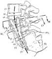
- FIGS. 1-3are lateral, posterior and anterior views of the lumbar and sacral portion of the spinal column depicting the visualized PAIFL and AAIFL extending cephalad and axially from the posterior laminectomy site and the anterior target point, respectively;
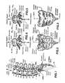
- FIG. 4is a sagittal caudal view of lumbar vertebrae depicting a TASIF spinal implant or rod within a TASIF axial bore formed following the visualized PAIFL or AAIFL of FIGS. 1-3;
- FIG. 5is a sagittal caudal view of lumbar vertebrae depicting a plurality, e.g., 2, TASIF spinal implants or rods within a like plurality of TASIF axial bores formed in parallel with the visualized PAIFL or AAIFL of FIGS. 1-3;
- FIG. 6is a simplified flow chart showing the principal surgical preparation steps of percutaneously accessing a posterior or anterior target point of the sacrum and forming a percutaneous tract following the visualized PAIFL or AAIFL of FIGS. 1-3, as well as subsequent steps of forming the TASIF bore(s) for treatment of accessed vertebral bodies and intervening discs and of implanting spinal implants therein;
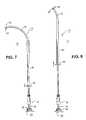
- FIG. 7is a plan view of one exemplary boring tool embodiment comprising an elongated drill shaft assembly and drill motor for forming a curved anterior or posterior TASIF axial bore, the drill bit having a 90° curve formed in the elongated drill drive shaft by retraction of an outer sheath;
- FIG. 8is a plan view of the boring tool of FIG. 7 with a reduced curvature formed in the elongated drill shaft assembly by adjustment of the outer sheath;
- FIG. 9is a cross-section view of the drill bit of FIGS. 7 and 8 with the curvature eliminated by full distal extension of the outer sheath to the distal end of the drill bit;
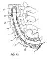
- FIGS. 10-13illustrate, in partial cross-section side views, one manner of forming a posterior TASIF axial bore through sacral and lumbar vertebrae and intervening discs axially aligned with the visualized PAIFL of FIGS. 1 and 2 using the boring tool of FIGS. 7-9;
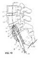
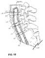
- FIGS. 14-18illustrate, in partial cross-section side views, one manner of forming an anterior TASIF axial bore through sacral and lumbar vertebrae and intervening discs axially aligned with the visualized AAIFL of FIGS. 1 and 2 using the boring tool of FIGS. 7-9;
- FIGS. 19-21illustrate a further exemplary boring tool embodiment comprising an elongated drill shaft assembly and drill motor for forming a curved anterior or posterior TASIF axial bore in the manner illustrated in FIGS. 10-18;
- FIGS. 22-25illustrate a still further exemplary boring tool embodiment comprising an elongated drill shaft assembly and drill motor for forming a curved anterior or posterior TASIF axial bore in the manner illustrated in FIGS. 10-18;
- FIG. 26depicts, in a partial cross-section side view, the formation of a plurality of curved TASIF axial bores that diverge apart from a common caudal section in the cephalad direction;
- FIGS. 27 and 28depict, in partial cross-section end views taken along lines 27 — 27 and 28 — 28 , respectively, of FIG. 26, the divergence of the plurality of curved TASIF axial bores.
- Certain of the toolsare selectively employed to form a percutaneous (i.e., through the skin) pathway from an anterior or posterior skin incision to a respective anterior or posterior position, e.g., a target point of a sacral surface or the cephalad end of a pilot hole bored through the sacrum and one or more lumbar vertebrae.
- the percutaneous pathwayis generally axially aligned with the AAIFL or the PAIFL extending from the respective anterior or posterior target point through at least one sacral vertebral body and one or more lumbar vertebral body in the cephalad direction as visualized by radiographic or fluoroscopic equipment.
- the AAIFL and PAIFLfollow the curvature of the vertebral bodies that they extend through in the cephalad direction.
- FIGS. 1-6Attention is first directed to the following description of FIGS. 1-6 is taken from the above-referenced parent provisional application No. 60/182,748.
- the acronyms TASF, AAFL, and PAFL used in the '748 applicationare changed to TASIF, AAIFL and PAIFL in this application to explicitly acknowledge that instruments can be introduced for inspection or treatments in addition to the fusion and fixation provided by spinal implants that may be inserted into the axial bores or pilot holes.
- FIGS. 1-3schematically illustrate the anterior and posterior TASIF surgical approaches in relation to the lumbar region of the spinal column
- FIGS. 4-5illustrate the location of the TASIF implant or pair of TASIF implants within a corresponding posterior TASIF axial bore 22 or anterior TASIF axial bore 152 or pair of TASIF axial bores 22 1 , 22 2 or 152 1 , 152 2
- Two TASIF axial bores and spinal implants or rodsare shown in FIG. 5 to illustrate that a plurality, that is two or more, of the same may be formed and/or employed in side by side relation parallel with the AAIFL or PAIFL.
- FIG. 1The lower regions of the spinal column comprising the coccyx, fused sacral vertebrae S 1 -S 5 forming the sacrum, and the lumbar vertebrae L 1 -L 5 described above are depicted in a lateral view in FIG. 1 .
- the series of adjacent vertebrae located within the human lumbar and sacral spinehave an anterior aspect, a posterior aspect and an axial aspect, and the lumbar vertebrae are separated by intact or damaged spinal discs labeled D 1 -D 5 in FIG. 1 .
- FIGS. 2 and 3depict the posterior and anterior view of the sacrum and coccyx.
- the method and apparatus for forming an anterior or posterior TASIF axial boreinitially involves accessing an anterior sacral position, e.g. an anterior target point at the junction of S 1 and S 2 depicted in FIGS. 1 and 3, or a posterior sacral position, e.g. a posterior laminectomy site of S 2 depicted in FIGS. 1 and 2.
- an anterior sacral positione.g. an anterior target point at the junction of S 1 and S 2 depicted in FIGS. 1 and 3
- a posterior sacral positione.g. a posterior laminectomy site of S 2 depicted in FIGS. 1 and 2.
- One (or more) visualized, imaginary, axial instrumentation/fusion lineextends cephalad and axially in the axial aspect through the series of adjacent vertebral bodies to be fused, L 4 and L 5 in this illustrated example.
- the visualized AAIFL through L 4 , D 4 , L 5 and D 5extends relatively straight from the anterior target point along S 1 depicted in FIGS
- the visualized PAIFLextends in the cephalad direction with more pronounced curvature from the posterior laminectomy site of S 2 depicted in FIGS. 1 and 2.
- FIG. 6depicts, in general terms, the surgical steps of accessing the anterior or posterior sacral positions illustrated in FIGS. 1-3 (S 100 ) forming posterior and anterior TASIF axial bores (S 200 ), optionally inspecting the discs and vertebral bodies, performing disc removal, disc augmentation, and vertebral bone reinforcement (S 300 ), and implanting posterior and anterior spinal implants and rods (S 400 ) in a simplified manner.
- step S 100access to the anterior or posterior sacral position, that is the anterior target point of FIG. 3 or the posterior laminectomy site of FIG. 2 is obtained, and the anterior or posterior sacral position is penetrated to provide a starting point for each axial bore that is to be created.
- an axial boreis bored from each point of penetration extending along either the PAIFL or AAIFL cephalad and axially through the vertebral bodies of the series of adjacent vertebrae and any intervertebral spinal discs (S 200 ).
- the axial boremay be visually inspected using an endoscope to determine if the procedures of step S 300 should be performed.
- Discoscopy or discectomy or disc augmentation of an intervening disc or discs or vertebroblasty of a vertebral bodymay be performed through the axial bore (S 300 ).
- an elongated TASIF spinal implant or rodis inserted into each axial bore to extend cephalad and axially through the vertebral bodies of the series of adjacent vertebrae and any intervertebral spinal discs (S 400 ).
- Other types of spinal implants for delivering therapies or alleviating pain as described abovemay be implanted in substitution for step S 400 .
- Step S 100preferably involves creation an anterior or posterior percutaneous pathway that enables introduction of further tools and instruments for forming an anterior or posterior percutaneous tract extending from the skin incision to the respective anterior or posterior target point of the sacral surface or, in some embodiments, the cephalad end of a pilot hole over which or through which further instruments are introduced as described in the above-referenced '222 application.
- An “anterior, presacral, percutaneous tract”extends through the “presacral space” anterior to the sacrum.
- the posterior percutaneous tract or the anterior, presacral, percutaneous tractis preferably used to bore one or more respective posterior or anterior TASIF bore in the cephalad direction through one or more lumbar vertebral bodies and intervening discs, if present.
- a single anterior or posterior TASIF boreis preferably aligned axially with the respective visualized AAIFL or PAIFL, and plural anterior or posterior TASIF bores are preferably aligned in parallel with the respective visualized AAIFL or PAIFL.
- Introduction of spinal implants and instruments for performing discectomies and/or disc and/or vertebral body augmentationis enabled by the provision of the percutaneous pathway and formation of the anterior or posterior TASIF bore(s).
- step S 100 in the anterior and/or posterior TASIF proceduresmay involve drilling a pilot hole, smaller in diameter than the TASIF axial bore, that tracks the AAIFL and/or PAIFL in order to complete the formation of the anterior and/or posterior percutaneous tracts.
- Step S 300may optionally be completed through the AAIFL/PAIFL pilot hole following step S 100 , rather than following the enlargement of the pilot hole to form the TASIF axial bore in step S 200 .
- the preferred embodiments of the present inventioninvolve methods and apparatus including surgical tool sets for forming pilot holes or curved, posterior and anterior, TASIF axial bores 22 or 152 or 22 1 . . . 22 n , or 152 1 . . . 152 n shown in FIGS. 4 and 5 in alignment with the curved, visualized AAIFL and PAIFL.
- the surgical tool setscomprise elongated drill shaft assemblies supporting distal boring tools, e.g., mechanical rotating drill bits, burrs, augurs, abraders, or the like (collectively referred to as boring heads or drill bits for convenience), that can be manipulated in use to form a selected curvature in a distal drill shaft segment and have sufficient torqueability to allow the user to rotate the curved distal segment into a desired boring plane from a proximal end of the elongated drill shaft assembly.
- distal boring toolse.g., mechanical rotating drill bits, burrs, augurs, abraders, or the like
- boring heads or drill bitsfor convenience
- the distal segmentis curved and urged into the desired boring plane so that the drill bit bores the next section of the TASIF axial bore at an angle to the previously bored caudal section of the TASIF axial bore resulting in an overall curvature in the TASIF axial bore aligned with the AAIFL or PAIFL.
- FIGS. 7-9show one exemplary boring tool 10 for boring a single one or a plurality of curved anterior or posterior TASIF axial bores aligned with the curved, visualized AAIFL or PAIFL as illustrated in FIGS. 10-18.
- the boring toolcomprises an elongated drill shaft assembly 12 and a drill motor 30 (shown in part) which may take any form. It will be understood that the drill motor 30 can be permanently attached to and form part of the proximal end of the elongated drill shaft assembly 12 , but is depicted herein as a separate, detachable drill motor.
- the elongated drill shaft assembly 12extends between an exposed proximal drive shaft end 14 at the proximal drill shaft assembly end 18 an exposed drill bit 20 at the distal drill shaft assembly end 24 .
- the exposed proximal drive shaft end 14is received within and attached to a chuck 32 of drill motor 30 in a manner well known in the art to rotate the drive shaft 26 extending from the drive shaft proximal end through the length of the elongated drill shaft assembly to the exposed distal drill bit 20 .
- the exposed distal drill bit 20may take any form of burr or auger or screw that can be rotated at a suitable speed to penetrate the dense and hard outer periostium and compact bone layers of the vertebral bodies and advance through the relatively softer, interiorly disposed, spongy bone.
- the drill bit 20is advanced in a curved path in the cephalad direction perforating each opposed face of each vertebral body and intervening disc while staying within the spongy bone of each vertebral body that is penetrated.
- the drill bit 20is preferably radiopaque so that its advancement through vertebral bodies can be observed employing conventional imaging equipment.
- the elongated drill shaft assembly 12further comprises a pre-curved inner sheath 34 having an inner sheath lumen 36 receiving and enclosing the drive shaft 26 , an outer sheath 40 having an outer sheath lumen 42 enclosing the inner sheath 34 , and a housing 16 that is attached to the proximal end of the inner sheath 34 .
- the outer sheath 40can be retracted proximally over the inner sheath 34 so that a distal segment of the inner sheath 34 is exposed or extended distally over the inner sheath 34 so that the distal segment thereof is enclosed within the outer sheath lumen 42 .
- the drive shaft 26is flexible and bendable and can formed of a single filament or multi-filar straight or coiled wire and is preferably radiopaque so that it can be observed using conventional imaging equipment.
- the distal end of the drive shaft 26is attached to the drill bit 20 by in any manner, e.g., by welding to a proximal surface thereof or by being crimped inside a crimp tube lumen of a proximally extending crimp tube 44 of the drill bit 20 as shown in FIG. 9 .
- the proximal end of the drive shaft 36is received within a further crimp or weld tube 46 that extends distally from the proximal exposed drive shaft end 14 as shown in FIG. 9 .
- the proximal exposed drive shaft endextends through a bearing in the proximal end wall of the housing 16 and is supported thereby for rotation by motor 30 .
- the outer diameters of the housing 16 and the drill bit 20exceed the outer diameter of the straight outer sheath 40 .
- the straight outer sheath 40can be moved back and forth over the pre-curved inner sheath 34 between a proximal position depicted in FIG. 7, a distal position depicted in FIG. 9 and any number of intermediate positions bounded by the housing 16 and drill bit 20 .
- the straight outer sheath 40is preferably formed of a stiff metal or plastic tube that is relatively stiffer and shorter in length than the more flexible, pre-curved inner sheath 34 .
- the more flexible, pre-curved inner sheath 34can be formed of a torqueable, plastic or metal, thin walled tubing and is pre-curved in a single plane to a suitable angle, e.g., about a 90° angle, in the distal segment thereof as shown in FIG. 7 .
- the angle and radius of curvature of the distal segmentcan be selected along with the length and stiffness of the outer sheath 40 to meet the needs of tracking the AAIFL or the PAIFL.
- the stiffness of the outer sheath 40is selected to enable it to be advanced distally to straighten the curvature of the distal segment of the inner sheath 34 .
- the outer sheath 40is flexible enough that it can be bent or curved within the confines of the curved TASIF axial bores as it is formed by the drill bit. In this way, the outer sheath can be advanced in the cephalad direction or retracted in the caudal direction and still conform to the curvature of the curved TASIF axial bore.
- FIGS. 10-13show steps included in step S 200 for forming a posterior TASIF axial bore 22 through sacral and lumbar vertebrae and intervening discs axially aligned with the visualized PAIFL of FIGS. 1 and 2 using the boring tool of FIGS. 7-9.
- the same stepscan be employed to form a pilot hole of step S 100 that can be enlarged in step S 200 .
- a small diameter bore forming toole.g. 3.0 mm diameter
- the boring toolis removed, and a guidewire having a threaded distal screw-in tip is advanced through the pilot hole and screwed into to the caudal end of the pilot hole and into cephalad portion of the L 4 body.
- An over-the-wire bore enlarging toolhaving a flexible body capable of tracking the curved guidewire is fitted over the proximal end of the guidewire and manually or mechanically rotated and advanced along it. In this way, the small pilot hole diameter is enlarged to form the anterior TASIF axial bore 22 having a diameter e.g. a 10.0 mm diameter, and the enlarging tool is then removed.
- the illustrated diameter of the posterior TASIF axial bore hole 22 relative to sizes of the vertebral bodiesis merely exemplary, and that it is contemplated that the pilot hole and bore hole diameters can range from about 1-10 mm and 3-30 mm, respectively.
- a plurality of such posterior TASIF axial bores 22 1 . . . 22 ncan be formed in side by side relation generally aligned with the PAIFL.
- the posterior surface of the sacrumis exposed in step S 100 as described in the above-referenced '222 and '748 applications.
- the area of the patient's skin surrounding the incision siteis surgically prepped, and the anus is excluded from the surgical field using adhesive drapes.
- the actual dermal entry sitemay be determined by the prone, preoperative CT scan or MRI study that maps the PAIFL.
- step S 100an incision is made in the patient's skin over the posterior sacral surface of S 2 , and the subcutaneous tissue is separated to expose the posteriorly extending, bony ridge of the posterior sacral surface.
- a small laminectomy 14is performed through the posterior ridge of the sacrum inferior. The thecal sac and nerve roots that are exposed by the laminectomy are gently retracted, and the terminal portion of the spinal canal is exposed.
- the elongated drill shaft assembly 12is axially aligned with the PAIFL at the posterior target point so that the initial penetration of the sacrum is substantially at right angles to the exposed sacral surface.
- a drill guide for receiving the drill drive shaft assembly for drilling or boring a TASIF axial bore from S 2 along the visualized PAIFL 20may optionally be attached to S 2 and extended posteriorly through the exposed spinal canal and skin incision.
- the straight outer sheath 40is fully distally extended to straighten the inner sheath 34 , and the drill bit 20 is rotated to commence boring a posterior TASIF axial bore 22 .
- the elongated drill shaft assembly 12thus advances anteriorly to form a straight segment or section of the posterior TASIF axial bore 22 .
- the progress of the drill bit 20is observed using conventional imaging equipment. As the elongated drill shaft assembly 12 is extended anteriorly, it is necessary to retract the straight outer sheath 34 proximally to allow the inner sheath to curve in the cephalad direction to introduce a curvature in the cephalad segment of the posterior TASIF axial bore 22 as shown in FIG. 11 . It is also necessary to orient and hold the proximal housing 16 so that the plane of curvature of the distal segment is aligned to the axis of the spine. This could be accomplished using external reference markings on the proximal housing 16 .
- the degree of curvature of the cephalad segment of the posterior TASIF axial bore 22is continually adjusted by incremental proximal and distal movements of the straight outer sheath 40 at flange 50 to expose more or less of the distal segment of the curved inner sheath 34 as shown in FIG. 12 .
- the drill bit 20advances through the sacral vertebrae in the cephalad direction and toward the lumbar vertebral bodies while staying within the spongy bone of each vertebral body.
- any number of vertebral bodies of the spinecan be bored through in the cephalad direction.
- FIGS. 14-16show steps included in step S 200 for forming an anterior TASIF axial bore 152 through sacral and lumbar vertebrae and intervening discs axially aligned with the visualized AAIFL of FIGS. 1 and 2 using the boring tool of FIGS. 7-9.
- the same stepscan be employed to form a pilot hole of step S 100 that can be enlarged in step S 200 .
- the illustrated diameter of the anterior TASIF axial bore hole 152 relative to sizes of the vertebral bodiesis merely exemplary, and that it is contemplated that the pilot holes and bore hole diameters can range from about 1-10 mm and 3-30 mm, respectively.
- a plurality of such anterior TASIF axial bores 152 1 . . . 152 ncan be formed in side by side relation generally aligned with the AAIFL.
- the elongated drill shaft assembly 12is axially aligned with the AAIFL at the anterior target point so that the initial penetration of the sacrum is substantially at right angles to the opposed faces of S 1 and L 5 cephalad to the sacral surface of penetration.
- This anterior sacral surface starting pointis accessed in step S 100 from an incision in the patient's skin alongside the coccyx and via a percutaneous tract formed in the pre-sacral space which may or may not include a tract forming structure or tool as disclosed in the above-referenced '222 and '748 applications.
- the straight outer sheath 40is either fully distally extended to straighten the inner sheath 34 or retracted slightly depending on the patient's anatomy to provide an optimal orientation to the AAIFL.
- the drill bit 20is rotated to commence boring an anterior TASIF axial bore 152 , and the elongated drill shaft assembly 12 advances anteriorly to form a relatively straight or slightly curved segment of the posterior TASIF axial bore 22 .
- the progress of the drill bit 20is observed using conventional imaging equipment.
- the elongated drill shaft assembly 12As the elongated drill shaft assembly 12 is extended in the cephalad direction through S 1 , D 5 (if present) and L 5 , it becomes necessary to retract the straight outer sheath 34 proximally to allow the inner sheath to curve in the cephalad direction to introduce a greater degree of curvature in the cephalad segment of the anterior TASIF axial bore 152 as shown in FIG. 15 .
- the degree of curvature of the cephalad segment of the anterior TASIF axial bore 152is continually adjusted by incremental proximal and distal movements of the straight outer sheath 40 at flange 50 to expose more or less of the distal segment of the curved inner sheath 34 as shown in FIG. 15 .
- the drill bit 20advances through the sacral vertebrae in the cephalad direction and through the lumbar vertebral bodies while staying within the spongy bone of each vertebral body.
- the drill bit 20is advanced across the opposed faces of vertebral bodies L 4 and L 5 with the outer sheath 40 fully advanced in the cephalad direction.
- This processresults in short relatively straight sections separated by more curved sections of the of the anterior TASIF axial bore 152 .
- the resulting anterior TASIF axial bore 152 shown in FIG. 18exhibits an overall curvature tracking the spinal curvature and the visualized AAIFL, but the curve radius varies, showing a shorter radius within the central portions of vertebral bodies L 5 and L 4 .
- FIGS. 19-21illustrate a further embodiment of an exemplary boring tool 110 comprising a drill motor 30 and an elongated drill shaft assembly 112 employing one or more tip deflection wire 104 (FIG. 21) for imparting a desired curvature in the distal segment of sheath 134 .
- the sheath 134extends from the distal end 124 into the housing 124 in the manner of sheath 34 depicted in FIG. 9, but it encloses an inner lumen 136 for receiving the drive shaft 126 and a radially offset tip deflection wire lumen 102 receiving a tip deflection wire 104 .
- the distal end of the drive shaft 126is attached to the drill bit 120 in the manner described above for attachment of the distal end of drive shaft 26 with the drill bit 20 .
- the proximal end of the drive shaft 126is attached to the proximal exposed drive shaft end 114 in the manner that the proximal end of the drive shaft 26 is attached to the proximal exposed drive shaft end 14 .
- the drive shaft 126may take any form including the depicted coiled wire form with or without a core wire extending through the coiled wire lumen.
- the tip deflection wire 104extends through the pull wire lumen extending along one side of the inner drive shaft sheath 134 between an attachment point at the distal end 124 and an attachment within housing 138 with distal segment curvature control ring 106 mounted on housing 138 .
- the distal segment of drive shaft sheath 134 distal to junction 136is more flexible than the proximal segment of drive shaft sheath 134 proximal to junction 136 .
- the distal segment curvature control ring 106is located over the cylindrical surface of housing 138 , and an inwardly extending member extends into an elongated groove 108 in the housing 138 where it is attached to the proximal end of the tip deflection wire 104 .
- tip deflection wire 104to form the curves in the drive shaft distal segment depicted in FIGS. 19 and 20 is effected by sliding the control ring 106 proximally from a rest or neutral position wherein the distal segment assumes a straight distal segment shape 1 ′ as depicted in broken lines in FIG. 19 .
- the length of the distal segment of the drive shaft 126 and the range of motion of the control ring 106 from the neutral positioncan be selected so as to form any angle or range of curvature that may be found desirable.
- the range of motion of the control ring 106 from the neutral positioncan be selected such that the control ring may be pushed distally from the neutral position to impart a curvature in the distal segment that is opposite to the curvatures depicted in FIGS. 19 and 20.
- the tip deflection wire 104can therefore be either a pull wire for retraction only or a tip deflection wire for retraction and extension.
- the boring tool 110can be employed to form the posterior and anterior TASIF axial bores 22 and 152 or a plurality of the same in the same manner as described above with respect to FIGS. 10-18.
- the curvature of the posterior and anterior TASIF axial bores 22 and 152is controlled by manipulation of the distal segment curvature control ring 106 as the drill bit 120 is advanced in the cephalad direction from the starting points depicted in FIGS. 10 and 14.
- FIGS. 22-25illustrate a further embodiment of an exemplary boring tool 210 comprising a drill motor 230 and an elongated drill shaft assembly 212 .
- the elongated drill shaft assembly 212further comprises a straight inner sheath 234 having an inner sheath lumen 236 receiving and enclosing the drive shaft 226 , a straight outer sheath 240 having an outer sheath lumen 242 enclosing the inner sheath 234 , and a housing 238 that is attached to the proximal end of the inner sheath 234 .
- the inner sheath 234is optional and can be eliminated to reduce the overall diameter of the elongated drill shaft assembly 212 .
- the drive shaft 226is flexible and bendable enough to be either be straight when extended distally or curved in use as described below and can formed of a single filament or multi-filar straight or coiled wire that is preferably radiopaque so that it can be observed using conventional imaging equipment.
- the distal end of the drive shaft 226is attached to the spherical drill bit 220 by in any manner, e.g., by welding to a proximal surface thereof or by being crimped inside a crimp tube lumen of a proximally extending crimp tube 244 of the drill bit 220 as shown in FIG. 23 .
- the proximal end of the drive shaft 236is received within a further crimp or weld tube 246 that extends distally from the proximal exposed drive shaft end 214 as shown in FIG. 23 .
- the proximal exposed drive shaft end 214extends through a bearing in the proximal end wall of the housing 238 and is supported thereby for rotation by motor 30 .
- the flexible outer sheath 240is generally circular in cross-section and extends between a push-pull proximal handle 250 and a distal end thereof.
- the outer sheath lumen 242is radially offset from the axis of the flexible outer sheath 240 so that the drill shaft 226 and optional inner sheath 234 extend through the outer sheath lumen to locate the drill bit 220 offset from the axis of the flexible outer sheath 240 as shown in FIGS. 23 and 24.
- a sleeve-shaped, thrust bearing 228 formed of a hard plastic or metal materialis disposed in the outer sheath distal end surrounding the distal end opening of the outer sheath lumen 242 and projecting slightly distally therefrom.
- the remaining exposed portion of the outer sheath 240is flexible and compressible to be advanced through a bore hole formed by the drill bit 220 .
- the outer diameters of the housing 238 and the drill bit 220exceed the outer diameter of the flexible outer sheath 240 .
- the flexible outer sheath 240can be moved back and forth over the inner sheath 234 between a proximal position depicted in FIG. 22 and a distal position depicted in FIG. 25 .
- the outer diameter of the drill bit 220is approximately equal to or slightly larger than the outer diameter of the outer sheath 240 as shown in FIGS. 23 and 24.
- a curvature in the distal segment of the outer and inner sheaths 240 and 234 toward the radial offset direction D(FIG. 23) is formed when the outer sheath 240 is advanced distally to its full extent as shown in FIG. 25 .
- the distal surface of the thrust bearing 228bears against the proximal spherical surface of the drill bit 220 when force is applied by pushing the outer sheath 240 distally at handle 250 and/or pulling the inner sheath 234 proximally at housing 238 .
- the axial offset of the outer sheath lumen 242 and the flexibility of the outer sheath 240 just proximally to thrust bearing 228cooperate to laterally deflect the drill bit 220 toward the radial offset direction D.
- the thinner wall of the outer sheath 240 in the radial offset directioncontributes to its axial compression and inducement of the depicted curvature. It will be understood that the angular deflection of the drill tip 220 and the range of curvature of the distal segment of the outer and inner sheaths 240 and 234 toward the radial offset direction D can be selected by the selection of materials and the offset of the outer sheath lumen 242 from the axis of outer sheath 240 .
- the boring tool 210can be employed to form the posterior and anterior TASIF axial bores 22 and 152 or a plurality of the same in the same manner as described above with respect to FIGS. 10-18.
- the curvature of each section of the posterior and anterior TASIF axial bores 22 and 152is controlled by proximal and distal manipulation of the outer sheath 240 with respect to inner sheath 234 as the drill bit 220 is advanced in the cephalad direction from the starting points depicted in FIGS. 10 and 14.
- the elongated drive shaft assembliescan be modified to provide fluid lumens for pumping flushing fluids into the TASIF axial bores at the distal ends thereof and for conveying flushing fluid and bone fragments proximally to the exterior of the patient's body.
- the elongated drive shaft assemblies and drill bitscan be modified to provide a guide wire lumen extending from the proximal to the distal ends thereof for advancement over a guidewire. Suitable drive motors for rotating a drive shaft over a guidewire and drive shaft assemblies having flushing capabilities are disclosed in U.S. Pat. No. 6,066,152, for example.
- a single posterior or anterior TASIF axial bore 22 or 152When a single posterior or anterior TASIF axial bore 22 or 152 is formed, it can be formed in axial or parallel alignment with the visualized axial AAIFL and PAIFL as described. Similarly, multiple posterior or anterior TASIF axial bores can be formed all in parallel alignment with the visualized axial AAIFL and PAIFL or with at least one such TASIF axial bore formed in axial alignment with the visualized axial AAIFL and PAIFL.
- multiple anterior or posterior TASIF axial borescan be formed all commencing at an anterior or posterior target point of FIGS. 1-3 and extending in the cephalad direction with each TASIF axial bore diverging apart from the other and away from the visualized axial AAIFL and PAIFL.
- the diverging TASIF axial boresterminate as spaced apart locations in a cephalad vertebral body or in separate cephalad vertebral bodies.
- FIGS. 6-27depict a group of three anterior TASIF axial bores 152 1 , 152 2 , 152 3 that are bored from a common caudal entrance bore section 152 ′ starting at the anterior target point and extending in the cephalad direction generally following the curvature of the AAIFL but diverging outwardly.
- the divergence from the common entry bore sectioncan start in the sacral vertebra or in L 5 or in L 4 or in any other cephalad vertebra that the bore extends into or through.
- a “tripod” of the diverging TASIF axial bores 152 1 , 152 2 , 152 3is formed as shown in FIGS. 26 and 27.
- the common caudal entrance bore section 152 ′ through S 1 , and traversing disc D 5 and part of L 4can be larger in diameter than the diverging TASIF axial bores 152 1 , 152 2 , 152 3 to accommodate the insertion of three elongated spinal implants therein. It is believed that the insertion of elongated spinal implants within the “tripod” of the diverging TASIF axial bores 152 1 , 152 2 , 152 3 can substantially strengthen and enhance fusion of L 4 , L 5 and S 1 .
- the diverging TASIF axial bores 152 1 , 152 2 , 152 3can be extended further than shown in FIGS. 25-27.
- the above described tool setscan be employed to bore a curved trans-sacral axial bore or pilot hole in alignment with the visualized AAIFL or PAIFL cephalad and axially through the vertebral bodies of a series of adjacent vertebrae and any intervertebral spinal discs without unintentially perforating through a side of a vertebra.
- the alignmentcan be axial alignment as shown in FIG. 4, or parallel alignment as shown in FIG. 5 or diverging alignment as shown in FIGS. 25-27.
- the boring headis angled at a selected boring angle, e.g., by inducing a selected curvature in the distal segment of a sheath surrounding the drive shaft, and the boring plane of the angled boring head is oriented, e.g., by rotating the proximal housing and sheath to rotate the elongated drill shaft assembly, as is found necessary to obtain the desired bore curvature and alignment in any given case.
- the curved, posterior and anterior TASIF axial bores 22 and 152 that are formed in step S 200 of FIG. 6 as described abovestart in the sacrum at the respective posterior and anterior target points and extend upwardly or cephalad through the vertebral body of S 1 or S 2 and through the cephalad vertebral bodies including L 5 and L 4 and the intervening discs denoted D 4 and D 5 in FIG. 1 .
- Discs D 4 and D 5are usually damaged or have degenerated between lumbar spine vertebrae and cause the pain experienced by patients requiring intervention and fusion of the vertebrae.
- An inspection of the vertebral bodies and discs along the sides of the posterior or anterior TASIF axial bore 22 or 152can be made using an elongated endoscope inserted therethrough (or through a pilot hole if one is formed earlier).
- a discectomy or disc augmentation and/or vertebroblastymay be performed pursuant to step S 300 of FIG. 6 through the posterior or anterior TASIF axial bore 22 or 152 to relieve the patients symptoms and aid in the fusion achieved by insertion of a spinal implant.
- materials or devicescan be inserted through the curved, posterior and anterior TASIF axial bores 22 and 152 to fit into excised disc space or damaged vertebral bodies.
- axial spinal implantscan be inserted into the above-described curved, posterior and anterior TASIF axial bores 22 and 152 .
- Such axial spinal implantscan be combined with laterally installed disc replacements or spacers.
Landscapes
- Health & Medical Sciences (AREA)
- Orthopedic Medicine & Surgery (AREA)
- Life Sciences & Earth Sciences (AREA)
- Engineering & Computer Science (AREA)
- Biomedical Technology (AREA)
- Surgery (AREA)
- Animal Behavior & Ethology (AREA)
- Veterinary Medicine (AREA)
- Public Health (AREA)
- Heart & Thoracic Surgery (AREA)
- General Health & Medical Sciences (AREA)
- Oral & Maxillofacial Surgery (AREA)
- Transplantation (AREA)
- Nuclear Medicine, Radiotherapy & Molecular Imaging (AREA)
- Neurology (AREA)
- Medical Informatics (AREA)
- Molecular Biology (AREA)
- Vascular Medicine (AREA)
- Cardiology (AREA)
- Dentistry (AREA)
- Physical Education & Sports Medicine (AREA)
- Chemical & Material Sciences (AREA)
- Dispersion Chemistry (AREA)
- Surgical Instruments (AREA)
- Prostheses (AREA)
Abstract
Description
Claims (15)
Priority Applications (12)
| Application Number | Priority Date | Filing Date | Title |
|---|---|---|---|
| US09/709,105US6790210B1 (en) | 2000-02-16 | 2000-11-10 | Methods and apparatus for forming curved axial bores through spinal vertebrae |
| US09/710,369US6740090B1 (en) | 2000-02-16 | 2000-11-10 | Methods and apparatus for forming shaped axial bores through spinal vertebrae |
| AU2001239763AAU2001239763A1 (en) | 2000-02-16 | 2001-02-14 | Apparatus for forming curved axial bores through spinal vertebrae |
| EP01914369AEP1265538A4 (en) | 2000-02-16 | 2001-02-14 | Apparatus for forming curved axial bores through spinal vertebrae |
| PCT/US2001/004744WO2001060262A1 (en) | 2000-02-16 | 2001-02-14 | Apparatus for forming shaped axial bores through spinal vertebrae |
| PCT/US2001/004603WO2001060232A2 (en) | 2000-02-16 | 2001-02-14 | Apparatus for forming curved axial bores through spinal vertebrae |
| JP2001559333AJP4352204B2 (en) | 2000-02-16 | 2001-02-14 | Device for forming a curved axial hole through the spine |
| JP2001559362AJP4292360B2 (en) | 2000-02-16 | 2001-02-14 | Device for forming a shaped axial hole through the spine |
| EP01910676AEP1257210A4 (en) | 2000-02-16 | 2001-02-14 | Apparatus for forming shaped axial bores through spinal vertebrae |
| AU2001238260AAU2001238260A1 (en) | 2000-02-16 | 2001-02-14 | Apparatus for forming shaped axial bores through spinal vertebrae |
| US10/853,476US7569056B2 (en) | 2000-02-16 | 2004-05-25 | Methods and apparatus for forming shaped axial bores through spinal vertebrae |
| US12/534,673US20090292287A1 (en) | 2000-02-16 | 2009-08-03 | Methods and apparatus for tools in axially oriented bores through spinal vertebrae |
Applications Claiming Priority (3)
| Application Number | Priority Date | Filing Date | Title |
|---|---|---|---|
| US18274800P | 2000-02-16 | 2000-02-16 | |
| US09/709,105US6790210B1 (en) | 2000-02-16 | 2000-11-10 | Methods and apparatus for forming curved axial bores through spinal vertebrae |
| US09/710,369US6740090B1 (en) | 2000-02-16 | 2000-11-10 | Methods and apparatus for forming shaped axial bores through spinal vertebrae |
Publications (1)
| Publication Number | Publication Date |
|---|---|
| US6790210B1true US6790210B1 (en) | 2004-09-14 |
Family
ID=36586000
Family Applications (4)
| Application Number | Title | Priority Date | Filing Date |
|---|---|---|---|
| US09/710,369Expired - LifetimeUS6740090B1 (en) | 2000-02-16 | 2000-11-10 | Methods and apparatus for forming shaped axial bores through spinal vertebrae |
| US09/709,105Expired - Fee RelatedUS6790210B1 (en) | 2000-02-16 | 2000-11-10 | Methods and apparatus for forming curved axial bores through spinal vertebrae |
| US10/853,476Expired - Fee RelatedUS7569056B2 (en) | 2000-02-16 | 2004-05-25 | Methods and apparatus for forming shaped axial bores through spinal vertebrae |
| US12/534,673AbandonedUS20090292287A1 (en) | 2000-02-16 | 2009-08-03 | Methods and apparatus for tools in axially oriented bores through spinal vertebrae |
Family Applications Before (1)
| Application Number | Title | Priority Date | Filing Date |
|---|---|---|---|
| US09/710,369Expired - LifetimeUS6740090B1 (en) | 2000-02-16 | 2000-11-10 | Methods and apparatus for forming shaped axial bores through spinal vertebrae |
Family Applications After (2)
| Application Number | Title | Priority Date | Filing Date |
|---|---|---|---|
| US10/853,476Expired - Fee RelatedUS7569056B2 (en) | 2000-02-16 | 2004-05-25 | Methods and apparatus for forming shaped axial bores through spinal vertebrae |
| US12/534,673AbandonedUS20090292287A1 (en) | 2000-02-16 | 2009-08-03 | Methods and apparatus for tools in axially oriented bores through spinal vertebrae |
Country Status (5)
| Country | Link |
|---|---|
| US (4) | US6740090B1 (en) |
| EP (2) | EP1257210A4 (en) |
| JP (2) | JP4292360B2 (en) |
| AU (2) | AU2001239763A1 (en) |
| WO (2) | WO2001060232A2 (en) |
Cited By (231)
| Publication number | Priority date | Publication date | Assignee | Title |
|---|---|---|---|---|
| US20030083662A1 (en)* | 2001-11-01 | 2003-05-01 | Middleton Lance M. | Orthopaedic implant fixation using an in-situ formed anchor |
| US20040117409A1 (en)* | 2001-03-03 | 2004-06-17 | Scahill Francis J | Application synchronisation |
| US20040255910A1 (en)* | 2003-01-30 | 2004-12-23 | Klaus Joos | Method, computer program, memory medium, and control and/or regulating device for operating an internal combustion engine, and an internal combustion engine in particular for a motor vehicle |
| US20050070908A1 (en)* | 2000-02-16 | 2005-03-31 | Cragg Andrew H. | Articulating spinal implant |
| US20050137607A1 (en)* | 2003-10-23 | 2005-06-23 | Assell Robert L. | Bone dilator system |
| US20050267481A1 (en)* | 2003-10-17 | 2005-12-01 | Allen Carl | Systems, devices and apparatuses for bony fixation and disk repair and replacement and methods related thereto |
| US20060135882A1 (en)* | 2004-10-15 | 2006-06-22 | Baxano, Inc. | Devices and methods for selective surgical removal of tissue |
| US20060149268A1 (en)* | 2004-11-19 | 2006-07-06 | Csaba Truckai | Bone treatment systems and methods |
| US7087058B2 (en)* | 2000-02-16 | 2006-08-08 | Trans1, Inc. | Method and apparatus for providing posterior or anterior trans-sacral access to spinal vertebrae |
| US20060235388A1 (en)* | 2005-04-15 | 2006-10-19 | Sdgi Holdings, Inc. | Pedicular tunneling for decompression and support |
| US20070010717A1 (en)* | 2000-02-16 | 2007-01-11 | Cragg Andrew H | Methods of performing procedures in the spine |
| US20070106383A1 (en)* | 2005-10-03 | 2007-05-10 | Abdou M S | Devices and methods for inter-vertebral orthopedic device placement |
| US20070118142A1 (en)* | 2005-11-18 | 2007-05-24 | Krueger John A | Device, system and method for delivering a curable material into bone |
| US20070142842A1 (en)* | 2005-11-18 | 2007-06-21 | Krueger John A | Device, system and method for delivering a curable material into bone |
| US20070185367A1 (en)* | 2006-02-02 | 2007-08-09 | Abdou M S | Treatment of Pain, Neurological Dysfunction and Neoplasms Using Radiation Delivery Catheters |
| US7309338B2 (en)* | 2000-02-16 | 2007-12-18 | Trans1 Inc. | Methods and apparatus for performing therapeutic procedures in the spine |
| US20080051812A1 (en)* | 2006-08-01 | 2008-02-28 | Baxano, Inc. | Multi-Wire Tissue Cutter |
| US20080065069A1 (en)* | 2006-09-07 | 2008-03-13 | Warsaw Orthopedic Inc. | Systems and methods for use in spinal support |
| US20080091217A1 (en)* | 2005-06-21 | 2008-04-17 | Brian Dross | Arthroscopic method and apparatus for tissue attachment to bone |
| WO2008031245A3 (en)* | 2006-09-14 | 2008-05-02 | Univ Bern | Surgical drilling device |
| US20080255563A1 (en)* | 2006-11-03 | 2008-10-16 | Innovative Spine | Instrumentation and method for providing surgical access to a spine |
| US20080312744A1 (en)* | 2004-07-27 | 2008-12-18 | Edward Vresilovic | Supplementation or replacement of a nucleus pulposus of an intervertebral disc |
| US20090005816A1 (en)* | 2007-06-26 | 2009-01-01 | Denardo Andrew J | Spinal rod, insertion device, and method of using |
| US20090023988A1 (en)* | 2007-07-20 | 2009-01-22 | Richard Wolf Gmbh | Endoscopic Instrument |
| US20090149878A1 (en)* | 2007-12-07 | 2009-06-11 | Csaba Truckai | Bone treatment systems and methods |
| US20090177206A1 (en)* | 2008-01-08 | 2009-07-09 | Zimmer Spine, Inc. | Instruments, implants, and methods for fixation of vertebral compression fractures |
| US7569056B2 (en) | 2000-02-16 | 2009-08-04 | Trans1 Inc. | Methods and apparatus for forming shaped axial bores through spinal vertebrae |
| US7578819B2 (en) | 2005-05-16 | 2009-08-25 | Baxano, Inc. | Spinal access and neural localization |
| US20090228014A1 (en)* | 2007-02-20 | 2009-09-10 | Stearns Stanley D | Treatment delivery system and method of use |
| US7608077B2 (en) | 2000-02-16 | 2009-10-27 | Trans1 Inc. | Method and apparatus for spinal distraction and fusion |
| US7641657B2 (en)* | 2003-06-10 | 2010-01-05 | Trans1, Inc. | Method and apparatus for providing posterior or anterior trans-sacral access to spinal vertebrae |
| US20100069929A1 (en)* | 2004-05-03 | 2010-03-18 | Abdou M S | Devices and methods for the preservation of spinal prosthesis function |
| US7682378B2 (en) | 2004-11-10 | 2010-03-23 | Dfine, Inc. | Bone treatment systems and methods for introducing an abrading structure to abrade bone |
| US20100076503A1 (en)* | 2007-02-07 | 2010-03-25 | N.M.B. Medical Applications Ltd | Bone implant |
| US20100106250A1 (en)* | 2004-08-23 | 2010-04-29 | Abdou M Samy | Bone fixation and fusion device |
| US7727263B2 (en)* | 2000-02-16 | 2010-06-01 | Trans1, Inc. | Articulating spinal implant |
| US7738969B2 (en) | 2004-10-15 | 2010-06-15 | Baxano, Inc. | Devices and methods for selective surgical removal of tissue |
| WO2010077359A1 (en)* | 2008-12-30 | 2010-07-08 | Mitchell Hardenbrook | Expandable interbody implant and method |
| US7776042B2 (en) | 2002-12-03 | 2010-08-17 | Trans1 Inc. | Methods and apparatus for provision of therapy to adjacent motion segments |
| US20100292695A1 (en)* | 2009-05-15 | 2010-11-18 | Zimmer, Inc. | Threaded, flexible implant and method for threading a curved hole |
| US20100292722A1 (en)* | 2009-05-18 | 2010-11-18 | Kaj Klaue | Device for forming a bore to facilitate insertion of an arcuate nail into a bone |
| US7857813B2 (en) | 2006-08-29 | 2010-12-28 | Baxano, Inc. | Tissue access guidewire system and method |
| WO2011005205A1 (en)* | 2009-07-10 | 2011-01-13 | Milux Holding S.A. | Hip joint instrument and method |
| US7887538B2 (en) | 2005-10-15 | 2011-02-15 | Baxano, Inc. | Methods and apparatus for tissue modification |
| US20110040329A1 (en)* | 2009-08-14 | 2011-02-17 | Ainsworth Stephen D | Spinal therapy device with fixated distraction distance |
| US7905905B2 (en) | 2000-02-16 | 2011-03-15 | Trans1, Inc. | Spinal mobility preservation apparatus |
| US7909873B2 (en) | 2006-12-15 | 2011-03-22 | Soteira, Inc. | Delivery apparatus and methods for vertebrostenting |
| US7918849B2 (en) | 2004-10-15 | 2011-04-05 | Baxano, Inc. | Devices and methods for tissue access |
| US7931689B2 (en) | 2000-02-28 | 2011-04-26 | Spineology Inc. | Method and apparatus for treating a vertebral body |
| US7938836B2 (en) | 2003-10-23 | 2011-05-10 | Trans1, Inc. | Driver assembly for simultaneous axial delivery of spinal implants |
| US7938830B2 (en) | 2004-10-15 | 2011-05-10 | Baxano, Inc. | Powered tissue modification devices and methods |
| US7955355B2 (en) | 2003-09-24 | 2011-06-07 | Stryker Spine | Methods and devices for improving percutaneous access in minimally invasive surgeries |
| US7959577B2 (en) | 2007-09-06 | 2011-06-14 | Baxano, Inc. | Method, system, and apparatus for neural localization |
| US7959634B2 (en) | 2004-03-29 | 2011-06-14 | Soteira Inc. | Orthopedic surgery access devices |
| US8002798B2 (en) | 2003-09-24 | 2011-08-23 | Stryker Spine | System and method for spinal implant placement |
| US8048080B2 (en) | 2004-10-15 | 2011-11-01 | Baxano, Inc. | Flexible tissue rasp |
| US8062298B2 (en) | 2005-10-15 | 2011-11-22 | Baxano, Inc. | Flexible tissue removal devices and methods |
| US8062300B2 (en) | 2006-05-04 | 2011-11-22 | Baxano, Inc. | Tissue removal with at least partially flexible devices |
| US8066773B2 (en) | 2004-01-28 | 2011-11-29 | F3 Technologies, Llc | Artificial intervertebral disc |
| US8092456B2 (en) | 2005-10-15 | 2012-01-10 | Baxano, Inc. | Multiple pathways for spinal nerve root decompression from a single access point |
| WO2012024162A1 (en)* | 2010-08-18 | 2012-02-23 | Interventional Spine, Inc. | Vertebral facet joint drill and method of use |
| US8142462B2 (en) | 2004-05-28 | 2012-03-27 | Cavitech, Llc | Instruments and methods for reducing and stabilizing bone fractures |
| US20120109229A1 (en)* | 2009-07-10 | 2012-05-03 | Milux Holdind Sa | Hip joint instrument and method |
| US8172855B2 (en) | 2004-11-24 | 2012-05-08 | Abdou M S | Devices and methods for inter-vertebral orthopedic device placement |
| US8192436B2 (en) | 2007-12-07 | 2012-06-05 | Baxano, Inc. | Tissue modification devices |
| US8221420B2 (en) | 2009-02-16 | 2012-07-17 | Aoi Medical, Inc. | Trauma nail accumulator |
| US8221397B2 (en) | 2004-10-15 | 2012-07-17 | Baxano, Inc. | Devices and methods for tissue modification |
| US8257356B2 (en) | 2004-10-15 | 2012-09-04 | Baxano, Inc. | Guidewire exchange systems to treat spinal stenosis |
| US8277506B2 (en) | 2008-06-24 | 2012-10-02 | Carefusion 2200, Inc. | Method and structure for stabilizing a vertebral body |
| WO2012134999A1 (en)* | 2011-03-25 | 2012-10-04 | Biomet Sports Medicine, Llc | Method and apparatus for forming a bone hole |
| USD669168S1 (en) | 2005-11-18 | 2012-10-16 | Carefusion 2200, Inc. | Vertebral augmentation needle |
| US8292896B2 (en) | 2004-10-05 | 2012-10-23 | Abdou M Samy | Devices and methods for inter-vertebral orthopedic device placement |
| US8303630B2 (en) | 2006-07-27 | 2012-11-06 | Samy Abdou | Devices and methods for the minimally invasive treatment of spinal stenosis |
| WO2012173616A1 (en)* | 2011-06-15 | 2012-12-20 | Empire Technology Development Llc | Punch tool |
| US8353911B2 (en) | 2007-05-21 | 2013-01-15 | Aoi Medical, Inc. | Extendable cutting member |
| US8366712B2 (en) | 2005-10-15 | 2013-02-05 | Baxano, Inc. | Multiple pathways for spinal nerve root decompression from a single access point |
| US8394102B2 (en) | 2009-06-25 | 2013-03-12 | Baxano, Inc. | Surgical tools for treatment of spinal stenosis |
| US8394129B2 (en) | 2011-03-10 | 2013-03-12 | Interventional Spine, Inc. | Method and apparatus for minimally invasive insertion of intervertebral implants |
| US8398641B2 (en) | 2008-07-01 | 2013-03-19 | Baxano, Inc. | Tissue modification devices and methods |
| US8409206B2 (en) | 2008-07-01 | 2013-04-02 | Baxano, Inc. | Tissue modification devices and methods |
| US8430881B2 (en) | 2004-10-15 | 2013-04-30 | Baxano, Inc. | Mechanical tissue modification devices and methods |
| US8439947B2 (en) | 2009-07-16 | 2013-05-14 | Howmedica Osteonics Corp. | Suture anchor implantation instrumentation system |
| US8518087B2 (en) | 2011-03-10 | 2013-08-27 | Interventional Spine, Inc. | Method and apparatus for minimally invasive insertion of intervertebral implants |
| US8568416B2 (en) | 2004-10-15 | 2013-10-29 | Baxano Surgical, Inc. | Access and tissue modification systems and methods |
| US8613745B2 (en) | 2004-10-15 | 2013-12-24 | Baxano Surgical, Inc. | Methods, systems and devices for carpal tunnel release |
| US20130345765A1 (en)* | 2012-06-20 | 2013-12-26 | Stryker Corporation | Systems and methods for off-axis tissue manipulation |
| US8652137B2 (en) | 2007-02-22 | 2014-02-18 | Spinal Elements, Inc. | Vertebral facet joint drill and method of use |
| US8690884B2 (en) | 2005-11-18 | 2014-04-08 | Carefusion 2200, Inc. | Multistate-curvature device and method for delivering a curable material into bone |
| US8740949B2 (en) | 2011-02-24 | 2014-06-03 | Spinal Elements, Inc. | Methods and apparatus for stabilizing bone |
| US8740942B2 (en) | 2004-02-06 | 2014-06-03 | Spinal Elements, Inc. | Vertebral facet joint prosthesis and method of fixation |
| WO2014083584A1 (en)* | 2012-11-28 | 2014-06-05 | Laura Raus | Device for percutaneous interstitial brachytherapy |
| US8795335B1 (en) | 2009-11-06 | 2014-08-05 | Samy Abdou | Spinal fixation devices and methods of use |
| US8801626B2 (en) | 2004-10-15 | 2014-08-12 | Baxano Surgical, Inc. | Flexible neural localization devices and methods |
| US8821494B2 (en) | 2012-08-03 | 2014-09-02 | Howmedica Osteonics Corp. | Surgical instruments and methods of use |
| US8840621B2 (en) | 2006-11-03 | 2014-09-23 | Innovative Spine, Inc. | Spinal access systems and methods |
| US8845639B2 (en) | 2008-07-14 | 2014-09-30 | Baxano Surgical, Inc. | Tissue modification devices |
| US8870920B2 (en) | 2005-10-07 | 2014-10-28 | M. Samy Abdou | Devices and methods for inter-vertebral orthopedic device placement |
| US8961516B2 (en) | 2005-05-18 | 2015-02-24 | Sonoma Orthopedic Products, Inc. | Straight intramedullary fracture fixation devices and methods |
| USD724733S1 (en) | 2011-02-24 | 2015-03-17 | Spinal Elements, Inc. | Interbody bone implant |
| US9060820B2 (en) | 2005-05-18 | 2015-06-23 | Sonoma Orthopedic Products, Inc. | Segmented intramedullary fracture fixation devices and methods |
| US9078740B2 (en) | 2013-01-21 | 2015-07-14 | Howmedica Osteonics Corp. | Instrumentation and method for positioning and securing a graft |
| US9101386B2 (en) | 2004-10-15 | 2015-08-11 | Amendia, Inc. | Devices and methods for treating tissue |
| US9155574B2 (en) | 2006-05-17 | 2015-10-13 | Sonoma Orthopedic Products, Inc. | Bone fixation device, tools and methods |
| US9168078B2 (en) | 2009-11-10 | 2015-10-27 | Carefusion 2200, Inc. | Apparatus and method for stylet-guided vertebral augmentation |
| US9192397B2 (en) | 2006-12-15 | 2015-11-24 | Gmedelaware 2 Llc | Devices and methods for fracture reduction |
| US9216048B2 (en) | 2009-03-18 | 2015-12-22 | Integrated Spinal Concepts, Inc. | Image-guided minimal-step placement of screw into bone |
| US9232954B2 (en) | 2009-08-20 | 2016-01-12 | Howmedica Osteonics Corp. | Flexible ACL instrumentation, kit and method |
| US9247952B2 (en) | 2004-10-15 | 2016-02-02 | Amendia, Inc. | Devices and methods for tissue access |
| US9259250B2 (en) | 2006-11-22 | 2016-02-16 | Sonoma Orthopedic Products, Inc. | Fracture fixation device, tools and methods |
| US9271765B2 (en) | 2011-02-24 | 2016-03-01 | Spinal Elements, Inc. | Vertebral facet joint fusion implant and method for fusion |
| US9277928B2 (en) | 2013-03-11 | 2016-03-08 | Interventional Spine, Inc. | Method and apparatus for minimally invasive insertion of intervertebral implants |
| US9277929B2 (en) | 2003-10-17 | 2016-03-08 | K2M, Inc. | Systems, devices and apparatuses for bony fixation and disk repair and replacement and methods related thereto |
| US9314253B2 (en) | 2008-07-01 | 2016-04-19 | Amendia, Inc. | Tissue modification devices and methods |
| US9402621B2 (en) | 2006-02-03 | 2016-08-02 | Biomet Sports Medicine, LLC. | Method for tissue fixation |
| US9402620B2 (en) | 2013-03-04 | 2016-08-02 | Howmedica Osteonics Corp. | Knotless filamentary fixation devices, assemblies and systems and methods of assembly and use |
| US9408716B1 (en) | 2013-12-06 | 2016-08-09 | Stryker European Holdings I, Llc | Percutaneous posterior spinal fusion implant construction and method |
| US9408599B2 (en) | 2006-02-03 | 2016-08-09 | Biomet Sports Medicine, Llc | Method and apparatus for coupling soft tissue to a bone |
| US9414833B2 (en) | 2006-02-03 | 2016-08-16 | Biomet Sports Medicine, Llc | Soft tissue repair assembly and associated method |
| US9421044B2 (en) | 2013-03-14 | 2016-08-23 | Spinal Elements, Inc. | Apparatus for bone stabilization and distraction and methods of use |
| USD765853S1 (en) | 2013-03-14 | 2016-09-06 | Spinal Elements, Inc. | Flexible elongate member with a portion configured to receive a bone anchor |
| USD765854S1 (en) | 2011-10-26 | 2016-09-06 | Spinal Elements, Inc. | Interbody bone implant |
| US9456855B2 (en) | 2013-09-27 | 2016-10-04 | Spinal Elements, Inc. | Method of placing an implant between bone portions |
| US9456829B2 (en) | 2004-10-15 | 2016-10-04 | Amendia, Inc. | Powered tissue modification devices and methods |
| US9463013B2 (en) | 2013-03-13 | 2016-10-11 | Stryker Corporation | Adjustable continuous filament structure and method of manufacture and use |
| US9468433B2 (en) | 2006-02-03 | 2016-10-18 | Biomet Sports Medicine, Llc | Method and apparatus for forming a self-locking adjustable loop |
| US9480485B2 (en) | 2006-12-15 | 2016-11-01 | Globus Medical, Inc. | Devices and methods for vertebrostenting |
| US9492158B2 (en) | 2006-02-03 | 2016-11-15 | Biomet Sports Medicine, Llc | Method and apparatus for coupling soft tissue to a bone |
| US9510821B2 (en) | 2006-02-03 | 2016-12-06 | Biomet Sports Medicine, Llc | Method and apparatus for coupling anatomical features |
| US9510875B2 (en) | 2013-03-14 | 2016-12-06 | Stryker European Holdings I, Llc | Systems and methods for percutaneous spinal fusion |
| US9522070B2 (en) | 2013-03-07 | 2016-12-20 | Interventional Spine, Inc. | Intervertebral implant |
| US9532777B2 (en) | 2006-02-03 | 2017-01-03 | Biomet Sports Medicine, Llc | Method and apparatus for coupling soft tissue to a bone |
| US9538998B2 (en) | 2006-02-03 | 2017-01-10 | Biomet Sports Medicine, Llc | Method and apparatus for fracture fixation |
| EP3030174A4 (en)* | 2013-08-05 | 2017-04-05 | Blumenthal, Scott L. | Vertebral endplate apparatus and method |
| AU2014277721B2 (en)* | 2010-08-18 | 2017-04-13 | Spinal Elements, Inc. | Tool and method for forming a lumen |
| US20170112552A1 (en)* | 2015-07-13 | 2017-04-27 | IntraFuse, LLC | Method of bone fixation |
| US9642661B2 (en) | 2006-02-03 | 2017-05-09 | Biomet Sports Medicine, Llc | Method and Apparatus for Sternal Closure |
| EP2046207A4 (en)* | 2006-07-13 | 2017-08-23 | K2M, Inc. | Devices and methods for stabilizing a spinal region |
| US9744050B1 (en) | 2013-12-06 | 2017-08-29 | Stryker European Holdings I, Llc | Compression and distraction system for percutaneous posterior spinal fusion |
| US9770278B2 (en) | 2014-01-17 | 2017-09-26 | Arthrex, Inc. | Dual tip guide wire |
| US9788826B2 (en) | 2013-03-11 | 2017-10-17 | Howmedica Osteonics Corp. | Filamentary fixation device and assembly and method of assembly, manufacture and use |
| US9795398B2 (en) | 2011-04-13 | 2017-10-24 | Howmedica Osteonics Corp. | Flexible ACL instrumentation, kit and method |
| US9801708B2 (en) | 2004-11-05 | 2017-10-31 | Biomet Sports Medicine, Llc | Method and apparatus for coupling soft tissue to a bone |
| US9814598B2 (en) | 2013-03-14 | 2017-11-14 | Quandary Medical, Llc | Spinal implants and implantation system |
| US9814499B2 (en) | 2014-09-30 | 2017-11-14 | Arthrex, Inc. | Intramedullary fracture fixation devices and methods |
| US9820784B2 (en) | 2013-03-14 | 2017-11-21 | Spinal Elements, Inc. | Apparatus for spinal fixation and methods of use |
| US9827020B2 (en) | 2013-03-14 | 2017-11-28 | Stryker European Holdings I, Llc | Percutaneous spinal cross link system and method |
| US9839530B2 (en) | 2007-06-26 | 2017-12-12 | DePuy Synthes Products, Inc. | Highly lordosed fusion cage |
| US9839450B2 (en) | 2013-09-27 | 2017-12-12 | Spinal Elements, Inc. | Device and method for reinforcement of a facet |
| US20170354431A1 (en)* | 2008-04-25 | 2017-12-14 | Medtronic Xomed, Inc. | Surgical instrument with internal irrigation |
| US9883951B2 (en) | 2012-08-30 | 2018-02-06 | Interventional Spine, Inc. | Artificial disc |
| US9895236B2 (en) | 2010-06-24 | 2018-02-20 | DePuy Synthes Products, Inc. | Enhanced cage insertion assembly |
| US9913727B2 (en) | 2015-07-02 | 2018-03-13 | Medos International Sarl | Expandable implant |
| US9931142B2 (en) | 2004-06-10 | 2018-04-03 | Spinal Elements, Inc. | Implant and method for facet immobilization |
| US9931223B2 (en) | 2008-04-05 | 2018-04-03 | DePuy Synthes Products, Inc. | Expandable intervertebral implant |
| US9986992B2 (en) | 2014-10-28 | 2018-06-05 | Stryker Corporation | Suture anchor and associated methods of use |
| US9993353B2 (en) | 2013-03-14 | 2018-06-12 | DePuy Synthes Products, Inc. | Method and apparatus for minimally invasive insertion of intervertebral implants |
| US9993349B2 (en) | 2002-06-27 | 2018-06-12 | DePuy Synthes Products, Inc. | Intervertebral disc |
| US10004493B2 (en) | 2006-09-29 | 2018-06-26 | Biomet Sports Medicine, Llc | Method for implanting soft tissue |
| US10022118B2 (en) | 2006-02-03 | 2018-07-17 | Biomet Sports Medicine, Llc | Method and apparatus for coupling soft tissue to a bone |
| US10058433B2 (en) | 2012-07-26 | 2018-08-28 | DePuy Synthes Products, Inc. | Expandable implant |
| US10092288B2 (en) | 2006-02-03 | 2018-10-09 | Biomet Sports Medicine, Llc | Method and apparatus for coupling soft tissue to a bone |
| US10136929B2 (en) | 2015-07-13 | 2018-11-27 | IntraFuse, LLC | Flexible bone implant |
| US10154863B2 (en) | 2015-07-13 | 2018-12-18 | IntraFuse, LLC | Flexible bone screw |
| US10159579B1 (en) | 2013-12-06 | 2018-12-25 | Stryker European Holdings I, Llc | Tubular instruments for percutaneous posterior spinal fusion systems and methods |
| US10251637B2 (en) | 2006-02-03 | 2019-04-09 | Biomet Sports Medicine, Llc | Soft tissue repair device and associated methods |
| US10265159B2 (en) | 2011-11-03 | 2019-04-23 | Biomet Sports Medicine, Llc | Method and apparatus for stitching tendons |
| US10265064B2 (en) | 2004-11-05 | 2019-04-23 | Biomet Sports Medicine, Llc | Soft tissue repair device and method |
| US10349931B2 (en) | 2006-09-29 | 2019-07-16 | Biomet Sports Medicine, Llc | Fracture fixation device |
| US10363028B2 (en) | 2011-11-10 | 2019-07-30 | Biomet Sports Medicine, Llc | Method for coupling soft tissue to a bone |
| US10368856B2 (en) | 2011-11-10 | 2019-08-06 | Biomet Sports Medicine, Llc | Apparatus for coupling soft tissue to a bone |
| US10390963B2 (en) | 2006-12-07 | 2019-08-27 | DePuy Synthes Products, Inc. | Intervertebral implant |
| US10398563B2 (en) | 2017-05-08 | 2019-09-03 | Medos International Sarl | Expandable cage |
| US10433977B2 (en) | 2008-01-17 | 2019-10-08 | DePuy Synthes Products, Inc. | Expandable intervertebral implant and associated method of manufacturing the same |
| US10448944B2 (en) | 2011-11-23 | 2019-10-22 | Howmedica Osteonics Corp. | Filamentary fixation device |
| US10485595B2 (en) | 2015-07-13 | 2019-11-26 | IntraFuse, LLC | Flexible bone screw |
| US10500062B2 (en) | 2009-12-10 | 2019-12-10 | DePuy Synthes Products, Inc. | Bellows-like expandable interbody fusion cage |
| US10517714B2 (en) | 2006-09-29 | 2019-12-31 | Biomet Sports Medicine, Llc | Ligament system for knee joint |
| US10517587B2 (en) | 2006-02-03 | 2019-12-31 | Biomet Sports Medicine, Llc | Method and apparatus for forming a self-locking adjustable loop |
| US10537436B2 (en) | 2016-11-01 | 2020-01-21 | DePuy Synthes Products, Inc. | Curved expandable cage |
| US10543107B2 (en) | 2009-12-07 | 2020-01-28 | Samy Abdou | Devices and methods for minimally invasive spinal stabilization and instrumentation |
| US10548740B1 (en) | 2016-10-25 | 2020-02-04 | Samy Abdou | Devices and methods for vertebral bone realignment |
| US10548741B2 (en) | 2010-06-29 | 2020-02-04 | DePuy Synthes Products, Inc. | Distractible intervertebral implant |
| US10568616B2 (en) | 2014-12-17 | 2020-02-25 | Howmedica Osteonics Corp. | Instruments and methods of soft tissue fixation |
| US10575961B1 (en) | 2011-09-23 | 2020-03-03 | Samy Abdou | Spinal fixation devices and methods of use |
| US10603029B2 (en) | 2006-02-03 | 2020-03-31 | Biomet Sports Medicine, Llc | Method and apparatus for coupling soft tissue to bone |
| US10610211B2 (en) | 2013-12-12 | 2020-04-07 | Howmedica Osteonics Corp. | Filament engagement system and methods of use |
| US10610217B2 (en) | 2006-09-29 | 2020-04-07 | Biomet Sports Medicine, Llc | Method and apparatus for forming a self-locking adjustable loop |
| US10695105B2 (en) | 2012-08-28 | 2020-06-30 | Samy Abdou | Spinal fixation devices and methods of use |
| US10695045B2 (en) | 2006-09-29 | 2020-06-30 | Biomet Sports Medicine, Llc | Method and apparatus for attaching soft tissue to bone |
| US10729421B2 (en) | 2006-02-03 | 2020-08-04 | Biomet Sports Medicine, Llc | Method and apparatus for soft tissue fixation |
| US10729423B2 (en) | 2007-04-10 | 2020-08-04 | Biomet Sports Medicine, Llc | Adjustable knotless loops |
| US10743925B2 (en) | 2006-09-29 | 2020-08-18 | Biomet Sports Medicine, Llc | Fracture fixation device |
| US10758361B2 (en) | 2015-01-27 | 2020-09-01 | Spinal Elements, Inc. | Facet joint implant |
| US10758221B2 (en) | 2013-03-14 | 2020-09-01 | Biomet Sports Medicine, Llc | Scaffold for spring ligament repair |
| USD902405S1 (en) | 2018-02-22 | 2020-11-17 | Stryker Corporation | Self-punching bone anchor inserter |
| US10857003B1 (en) | 2015-10-14 | 2020-12-08 | Samy Abdou | Devices and methods for vertebral stabilization |
| US10888433B2 (en) | 2016-12-14 | 2021-01-12 | DePuy Synthes Products, Inc. | Intervertebral implant inserter and related methods |
| US10940016B2 (en) | 2017-07-05 | 2021-03-09 | Medos International Sarl | Expandable intervertebral fusion cage |
| US10973648B1 (en) | 2016-10-25 | 2021-04-13 | Samy Abdou | Devices and methods for vertebral bone realignment |
| US11006982B2 (en) | 2012-02-22 | 2021-05-18 | Samy Abdou | Spinous process fixation devices and methods of use |
| US11065103B2 (en) | 2006-02-03 | 2021-07-20 | Biomet Sports Medicine, Llc | Method and apparatus for fixation of an ACL graft |
| US11173040B2 (en) | 2012-10-22 | 2021-11-16 | Cogent Spine, LLC | Devices and methods for spinal stabilization and instrumentation |
| US11179248B2 (en) | 2018-10-02 | 2021-11-23 | Samy Abdou | Devices and methods for spinal implantation |
| US11259792B2 (en) | 2006-02-03 | 2022-03-01 | Biomet Sports Medicine, Llc | Method and apparatus for coupling anatomical features |
| US11259794B2 (en) | 2006-09-29 | 2022-03-01 | Biomet Sports Medicine, Llc | Method for implanting soft tissue |
| US11304733B2 (en) | 2020-02-14 | 2022-04-19 | Spinal Elements, Inc. | Bone tie methods |
| US11311287B2 (en) | 2006-02-03 | 2022-04-26 | Biomet Sports Medicine, Llc | Method for tissue fixation |
| US11331094B2 (en) | 2013-04-22 | 2022-05-17 | Stryker Corporation | Method and apparatus for attaching tissue to bone |
| US11344424B2 (en) | 2017-06-14 | 2022-05-31 | Medos International Sarl | Expandable intervertebral implant and related methods |
| US11426286B2 (en) | 2020-03-06 | 2022-08-30 | Eit Emerging Implant Technologies Gmbh | Expandable intervertebral implant |
| US11426290B2 (en) | 2015-03-06 | 2022-08-30 | DePuy Synthes Products, Inc. | Expandable intervertebral implant, system, kit and method |
| US11446156B2 (en) | 2018-10-25 | 2022-09-20 | Medos International Sarl | Expandable intervertebral implant, inserter instrument, and related methods |
| US11452607B2 (en) | 2010-10-11 | 2022-09-27 | DePuy Synthes Products, Inc. | Expandable interspinous process spacer implant |
| US11457959B2 (en) | 2019-05-22 | 2022-10-04 | Spinal Elements, Inc. | Bone tie and bone tie inserter |
| US11464552B2 (en) | 2019-05-22 | 2022-10-11 | Spinal Elements, Inc. | Bone tie and bone tie inserter |
| US11478275B2 (en) | 2014-09-17 | 2022-10-25 | Spinal Elements, Inc. | Flexible fastening band connector |
| US11510788B2 (en) | 2016-06-28 | 2022-11-29 | Eit Emerging Implant Technologies Gmbh | Expandable, angularly adjustable intervertebral cages |
| US11596523B2 (en) | 2016-06-28 | 2023-03-07 | Eit Emerging Implant Technologies Gmbh | Expandable and angularly adjustable articulating intervertebral cages |
| US11612491B2 (en) | 2009-03-30 | 2023-03-28 | DePuy Synthes Products, Inc. | Zero profile spinal fusion cage |
| US11612391B2 (en) | 2007-01-16 | 2023-03-28 | Biomet Sports Medicine, Llc | Soft tissue repair device and associated methods |
| US11752009B2 (en) | 2021-04-06 | 2023-09-12 | Medos International Sarl | Expandable intervertebral fusion cage |
| US11850160B2 (en) | 2021-03-26 | 2023-12-26 | Medos International Sarl | Expandable lordotic intervertebral fusion cage |
| US11911287B2 (en) | 2010-06-24 | 2024-02-27 | DePuy Synthes Products, Inc. | Lateral spondylolisthesis reduction cage |
| USRE49973E1 (en) | 2013-02-28 | 2024-05-21 | DePuy Synthes Products, Inc. | Expandable intervertebral implant, system, kit and method |
| US12090064B2 (en) | 2022-03-01 | 2024-09-17 | Medos International Sarl | Stabilization members for expandable intervertebral implants, and related systems and methods |
| US12096928B2 (en) | 2009-05-29 | 2024-09-24 | Biomet Sports Medicine, Llc | Method and apparatus for coupling soft tissue to a bone |
| US12245759B2 (en) | 2008-08-22 | 2025-03-11 | Biomet Sports Medicine, Llc | Method and apparatus for coupling soft tissue to bone |
| US12329373B2 (en) | 2011-05-02 | 2025-06-17 | Biomet Sports Medicine, Llc | Method and apparatus for soft tissue fixation |
| US12369952B2 (en) | 2021-12-10 | 2025-07-29 | Spinal Elements, Inc. | Bone tie and portal |
| US12419632B2 (en) | 2008-08-22 | 2025-09-23 | Biomet Sports Medicine, Llc | Method and apparatus for coupling anatomical features |
| US12440242B2 (en) | 2024-04-29 | 2025-10-14 | Spinal Elements, Inc. | Flexible fastening band connector |
Families Citing this family (180)
| Publication number | Priority date | Publication date | Assignee | Title |
|---|---|---|---|---|
| US6783515B1 (en)* | 1999-09-30 | 2004-08-31 | Arthrocare Corporation | High pressure delivery system |
| US7632274B2 (en)* | 2000-02-16 | 2009-12-15 | Trans1 Inc. | Thin cutter blades with retaining film for preparing intervertebral disc spaces |
| US7258692B2 (en)* | 2000-03-07 | 2007-08-21 | Zimmer, Inc. | Method and apparatus for reducing femoral fractures |
| US20030220646A1 (en)* | 2002-05-23 | 2003-11-27 | Thelen Sarah L. | Method and apparatus for reducing femoral fractures |
| SE520688C2 (en)* | 2000-04-11 | 2003-08-12 | Bone Support Ab | An injectable bone mineral replacement material |
| SE517168C2 (en)* | 2000-07-17 | 2002-04-23 | Bone Support Ab | A composition for an injectable bone mineral replacement material |
| US6679886B2 (en)* | 2000-09-01 | 2004-01-20 | Synthes (Usa) | Tools and methods for creating cavities in bone |
| US6746451B2 (en)* | 2001-06-01 | 2004-06-08 | Lance M. Middleton | Tissue cavitation device and method |
| US20030050644A1 (en)* | 2001-09-11 | 2003-03-13 | Boucher Ryan P. | Systems and methods for accessing and treating diseased or fractured bone employing a guide wire |
| SE522098C2 (en)* | 2001-12-20 | 2004-01-13 | Bone Support Ab | Artificial bone mineral substitute material useful as an X-ray contrast medium comprises ceramic and water soluble non-ionic X-ray contrast agent |
| US20030220643A1 (en)* | 2002-05-24 | 2003-11-27 | Ferree Bret A. | Devices to prevent spinal extension |
| WO2003101308A1 (en)* | 2002-06-04 | 2003-12-11 | Office Of Technology Licensing Stanford University | Device and method for rapid aspiration and collection of body tissue from within an enclosed body space |
| JP2004097790A (en)* | 2002-07-16 | 2004-04-02 | Nakanishi:Kk | Medical purpose hand piece and cutting tool |
| US8808284B2 (en) | 2008-09-26 | 2014-08-19 | Relievant Medsystems, Inc. | Systems for navigating an instrument through bone |
| US8361067B2 (en) | 2002-09-30 | 2013-01-29 | Relievant Medsystems, Inc. | Methods of therapeutically heating a vertebral body to treat back pain |
| US6907884B2 (en) | 2002-09-30 | 2005-06-21 | Depay Acromed, Inc. | Method of straddling an intraosseous nerve |
| US7258690B2 (en) | 2003-03-28 | 2007-08-21 | Relievant Medsystems, Inc. | Windowed thermal ablation probe |
| US8613744B2 (en) | 2002-09-30 | 2013-12-24 | Relievant Medsystems, Inc. | Systems and methods for navigating an instrument through bone |
| WO2004043271A1 (en)* | 2002-11-08 | 2004-05-27 | Sdgi Holdings, Inc. | Transpedicular intervertebral disk access methods and devices |
| US7329267B2 (en)* | 2002-12-23 | 2008-02-12 | Boston Scientific Scimed, Inc. | Medical cutting devices and methods of use |
| SE0300620D0 (en)* | 2003-03-05 | 2003-03-05 | Bone Support Ab | A new bone substitute composition |
| US7582092B2 (en) | 2003-06-25 | 2009-09-01 | Depuy Products, Inc. | Assembly tool for modular implants and associated method |
| US8998919B2 (en) | 2003-06-25 | 2015-04-07 | DePuy Synthes Products, LLC | Assembly tool for modular implants, kit and associated method |
| US7074224B2 (en)* | 2003-06-25 | 2006-07-11 | Depuy Products, Inc. | Modular tapered reamer for bone preparation and associated method |
| US20040267267A1 (en)* | 2003-06-25 | 2004-12-30 | Daniels David Wayne | Non-linear reamer for bone preparation and associated method |
| US7297166B2 (en) | 2003-06-25 | 2007-11-20 | Depuy Products, Inc. | Assembly tool for modular implants and associated method |
| SE0302983D0 (en) | 2003-11-11 | 2003-11-11 | Bone Support Ab | Apparatus for providing spongy bone with bone replacement and / or bone strengthening material and associated method |
| US20050113843A1 (en)* | 2003-11-25 | 2005-05-26 | Arramon Yves P. | Remotely actuated system for bone cement delivery |
| US20050113836A1 (en)* | 2003-11-25 | 2005-05-26 | Lozier Antony J. | Expandable reamer |
| US7785328B2 (en)* | 2003-12-30 | 2010-08-31 | Depuy Products, Inc. | Minimally invasive bone miller apparatus |
| US7879037B2 (en)* | 2004-02-11 | 2011-02-01 | Medtronic Xomed, Inc. | High speed surgical cutting instrument |
| US20060064101A1 (en)* | 2004-02-12 | 2006-03-23 | Arthrocare Corporation | Bone access system |
| US8784421B2 (en) | 2004-03-03 | 2014-07-22 | Boston Scientific Scimed, Inc. | Apparatus and methods for removing vertebral bone and disc tissue |
| US20050209610A1 (en) | 2004-03-03 | 2005-09-22 | Scimed Life Systems, Inc. | Radially adjustable tissue removal device |
| US7604636B1 (en)* | 2004-04-20 | 2009-10-20 | Biomet Sports Medicine, Llc | Method and apparatus for arthroscopic tunneling |
| US7722612B2 (en)* | 2004-05-19 | 2010-05-25 | Sintea Biotech S.P.A. | Devices, kit and method for kyphoplasty |
| JP2008503275A (en)* | 2004-06-16 | 2008-02-07 | ウォーソー・オーソペディック・インコーポレーテッド | Surgical instruments and methods for treatment of spinal structures |
| SE527528C2 (en)* | 2004-06-22 | 2006-04-04 | Bone Support Ab | Apparatus for the preparation of curable pulp and use of the apparatus |
| JP2008508980A (en)* | 2004-08-09 | 2008-03-27 | トランス1,インク. | Nucleus nucleus prosthesis device and method |
| WO2006034436A2 (en) | 2004-09-21 | 2006-03-30 | Stout Medical Group, L.P. | Expandable support device and method of use |
| US8267969B2 (en) | 2004-10-20 | 2012-09-18 | Exactech, Inc. | Screw systems and methods for use in stabilization of bone structures |
| US8226690B2 (en) | 2005-07-22 | 2012-07-24 | The Board Of Trustees Of The Leland Stanford Junior University | Systems and methods for stabilization of bone structures |
| US8241330B2 (en) | 2007-01-11 | 2012-08-14 | Lanx, Inc. | Spinous process implants and associated methods |
| US9055981B2 (en) | 2004-10-25 | 2015-06-16 | Lanx, Inc. | Spinal implants and methods |
| US20060178674A1 (en)* | 2005-02-08 | 2006-08-10 | Mcintyre John | Surgical apparatus having configurable portions |
| US20060229624A1 (en) | 2005-03-31 | 2006-10-12 | Zimmer Technology, Inc. | Orthopaedic cutting instrument and method |
| EP1903949A2 (en) | 2005-07-14 | 2008-04-02 | Stout Medical Group, L.P. | Expandable support device and method of use |
| WO2009091960A2 (en)* | 2005-07-22 | 2009-07-23 | Vertiflex, Inc. | Tissue splitter |
| US8523865B2 (en) | 2005-07-22 | 2013-09-03 | Exactech, Inc. | Tissue splitter |
| US20070244562A1 (en)* | 2005-08-26 | 2007-10-18 | Magellan Spine Technologies, Inc. | Spinal implants and methods of providing dynamic stability to the spine |
| US20070050028A1 (en)* | 2005-08-26 | 2007-03-01 | Conner E S | Spinal implants and methods of providing dynamic stability to the spine |
| US8167915B2 (en) | 2005-09-28 | 2012-05-01 | Nuvasive, Inc. | Methods and apparatus for treating spinal stenosis |
| EP1948041A2 (en)* | 2005-10-24 | 2008-07-30 | Nexgen Spine, Inc. | Intervertebral disc replacement and associated instrumentation |
| US20070162062A1 (en)* | 2005-12-08 | 2007-07-12 | Norton Britt K | Reciprocating apparatus and methods for removal of intervertebral disc tissues |
| US8486077B1 (en)* | 2006-01-05 | 2013-07-16 | Ezriel E. Kornel | Percutaneous posterolateral spine fusion |
| US7914534B2 (en)* | 2006-03-28 | 2011-03-29 | Loubert Suddaby | Disk preparation tool |
| EP2023864B1 (en) | 2006-05-01 | 2019-07-10 | Stout Medical Group, L.P. | Expandable support device |
| US8109957B2 (en) | 2006-06-30 | 2012-02-07 | Depuy Spine, Inc. | Disc nucleus removal devices and methods |
| DE102006030689A1 (en)* | 2006-07-04 | 2008-01-10 | Helmut-Schmidt-Universität Universität der Bundeswehr Hamburg | Tool e.g. laser tool, positioning device for use in medical field, has shaft connected with tool in area of ends of shaft over supporting unit and formed as curved guidance in section wise, where supporting unit is guided along guidance |
| US8834526B2 (en) | 2006-08-09 | 2014-09-16 | Rolando Garcia | Methods and apparatus for treating spinal stenosis |
| US8597298B2 (en) | 2006-09-29 | 2013-12-03 | DePuy Synthes Products, LLC | Proximal reamer |
| US7963967B1 (en)* | 2006-10-12 | 2011-06-21 | Woodse Enterprises, Inc. | Bone preparation tool |
| US20090082775A1 (en)* | 2006-10-25 | 2009-03-26 | Moti Altarac | Spondylolisthesis reduction system and method |
| US8096996B2 (en)* | 2007-03-20 | 2012-01-17 | Exactech, Inc. | Rod reducer |
| US20080114364A1 (en)* | 2006-11-15 | 2008-05-15 | Aoi Medical, Inc. | Tissue cavitation device and method |
| US9265532B2 (en) | 2007-01-11 | 2016-02-23 | Lanx, Inc. | Interspinous implants and methods |
| US20080208196A1 (en)* | 2007-02-26 | 2008-08-28 | Team-At-Work, Inc. | Method and device for restoring spinal disc function |
| WO2008128067A2 (en)* | 2007-04-11 | 2008-10-23 | Eduardo Gonzalez-Hernandez | Curved assembly for reattachment of fragmented bone segments |
| WO2008128105A1 (en)* | 2007-04-12 | 2008-10-23 | Texas Scottish Rite Hospital For Children | Orthopedic fastener for stabilization and fixation |
| US20090088789A1 (en)* | 2007-09-28 | 2009-04-02 | O'neil Michael J | Balloon With Shape Control For Spinal Procedures |
| US8556912B2 (en) | 2007-10-30 | 2013-10-15 | DePuy Synthes Products, LLC | Taper disengagement tool |
| US8518050B2 (en) | 2007-10-31 | 2013-08-27 | DePuy Synthes Products, LLC | Modular taper assembly device |
| US20090125032A1 (en)* | 2007-11-14 | 2009-05-14 | Gutierrez Robert C | Rod removal instrument |
| WO2009067568A1 (en)* | 2007-11-19 | 2009-05-28 | Magellan Spine Technologies, Inc. | Spinal implants and methods |
| CA2781407A1 (en) | 2008-01-14 | 2009-07-23 | Michael P. Brenzel | Apparatus and methods for fracture repair |
| US9345517B2 (en) | 2008-02-02 | 2016-05-24 | Globus Medical, Inc. | Pedicle screw having a removable rod coupling |
| WO2009097623A2 (en)* | 2008-02-02 | 2009-08-06 | Texas Scottish Rite Hospital For Children | Pedicle screw |
| US9579126B2 (en) | 2008-02-02 | 2017-02-28 | Globus Medical, Inc. | Spinal rod link reducer |
| US9408641B2 (en)* | 2008-02-02 | 2016-08-09 | Globus Medical, Inc. | Spinal rod link reducer |
| KR100884211B1 (en)* | 2008-06-26 | 2009-02-18 | 이달호 | Pizotom for maxillary sinus elevation treatment |
| US20100016906A1 (en)* | 2008-07-21 | 2010-01-21 | Abdou M Samy | Device and method to access the anterior column of the spine |
| US20100076476A1 (en)* | 2008-07-25 | 2010-03-25 | To John T | Systems and methods for cable-based tissue removal |
| GB0813818D0 (en)* | 2008-07-29 | 2008-09-03 | Depuy Int Ltd | An instrument for forming a cavity within a bone |
| US20100036495A1 (en)* | 2008-08-07 | 2010-02-11 | PX Spine Corporation | Device and method for treating spine |
| CH700056B1 (en) | 2008-12-12 | 2012-04-13 | Med Titan Spine Gmbh | Surgical instrument. |
| US10028753B2 (en) | 2008-09-26 | 2018-07-24 | Relievant Medsystems, Inc. | Spine treatment kits |
| CA2737374C (en)* | 2008-09-26 | 2017-03-28 | Relievant Medsystems, Inc. | Systems and methods for navigating an instrument through bone |
| US8167882B2 (en)* | 2008-09-30 | 2012-05-01 | Depuy Products, Inc. | Minimally invasive bone miller apparatus |
| US20100211176A1 (en) | 2008-11-12 | 2010-08-19 | Stout Medical Group, L.P. | Fixation device and method |
| WO2010056895A1 (en) | 2008-11-12 | 2010-05-20 | Stout Medical Group, L.P. | Fixation device and method |
| US8454706B2 (en)* | 2009-02-25 | 2013-06-04 | Brian C. de Beaubien | Antibiotic delivery system and method for treating an infected synovial joint during re-implantation of an orthopedic prosthesis |
| US20100228301A1 (en)* | 2009-03-09 | 2010-09-09 | Greenhalgh E Skott | Attachment device and methods of use |
| US9173760B2 (en) | 2009-04-03 | 2015-11-03 | Metamodix, Inc. | Delivery devices and methods for gastrointestinal implants |
| ES2503553T3 (en) | 2009-04-03 | 2014-10-07 | Metamodix, Inc. | Modular Gastrointestinal Prosthesis |
| US8702641B2 (en) | 2009-04-03 | 2014-04-22 | Metamodix, Inc. | Gastrointestinal prostheses having partial bypass configurations |
| US9278019B2 (en) | 2009-04-03 | 2016-03-08 | Metamodix, Inc | Anchors and methods for intestinal bypass sleeves |
| US8801739B2 (en)* | 2009-04-17 | 2014-08-12 | Spine View, Inc. | Devices and methods for arched roof cutters |
| US8491585B2 (en)* | 2009-05-06 | 2013-07-23 | Kambiz Hannani | Methods and systems for minimally invasive lateral decompression |
| US20100298832A1 (en)* | 2009-05-20 | 2010-11-25 | Osseon Therapeutics, Inc. | Steerable curvable vertebroplasty drill |
| AU2010271294B2 (en) | 2009-07-10 | 2015-09-03 | Metamodix, Inc. | External anchoring configurations for modular gastrointestinal prostheses |
| WO2011017712A2 (en)* | 2009-08-07 | 2011-02-10 | Exatech, Inc. | Systems and methods for stabilization of bone structures, including thorocolumbar stabilization systems and methods |
| US10383629B2 (en)* | 2009-08-10 | 2019-08-20 | Covidien Lp | System and method for preventing reprocessing of a powered surgical instrument |
| US8568417B2 (en) | 2009-12-18 | 2013-10-29 | Charles River Engineering Solutions And Technologies, Llc | Articulating tool and methods of using |
| US8348950B2 (en) | 2010-01-04 | 2013-01-08 | Zyga Technology, Inc. | Sacroiliac fusion system |
| WO2011091052A1 (en)* | 2010-01-20 | 2011-07-28 | Kyle Taylor | Apparatus and methods for bone access and cavity preparation |
| US8696672B2 (en)* | 2010-01-22 | 2014-04-15 | Baxano Surgical, Inc. | Abrading tool for preparing intervertebral disc spaces |
| US9180137B2 (en) | 2010-02-09 | 2015-11-10 | Bone Support Ab | Preparation of bone cement compositions |
| US20110264098A1 (en)* | 2010-02-26 | 2011-10-27 | Cobbs Charles S | Minimally invasive systems, devices, and surgical methods for performing arthrodesis in the spine |
| WO2011112615A1 (en) | 2010-03-08 | 2011-09-15 | Krinke Todd A | Apparatus and methods for securing a bone implant |
| US20110251616A1 (en)* | 2010-04-12 | 2011-10-13 | K2M, Inc. | Expandable reamer and method of use |
| US9125671B2 (en) | 2010-04-29 | 2015-09-08 | Dfine, Inc. | System for use in treatment of vertebral fractures |
| US8900251B2 (en)* | 2010-05-28 | 2014-12-02 | Zyga Technology, Inc | Radial deployment surgical tool |
| US8533921B2 (en) | 2010-06-15 | 2013-09-17 | DePuy Synthes Products, LLC | Spiral assembly tool |
| TWI579007B (en) | 2010-07-02 | 2017-04-21 | 艾格諾福斯保健公司 | Use of bone regenerative material |
| EP2608747A4 (en) | 2010-08-24 | 2015-02-11 | Flexmedex Llc | Support device and method for use |
| US9095452B2 (en) | 2010-09-01 | 2015-08-04 | DePuy Synthes Products, Inc. | Disassembly tool |
| US9149286B1 (en) | 2010-11-12 | 2015-10-06 | Flexmedex, LLC | Guidance tool and method for use |
| US9320535B2 (en)* | 2010-11-15 | 2016-04-26 | Spine View, Inc. | Tissue removal system with retention mechanism |
| US9358122B2 (en) | 2011-01-07 | 2016-06-07 | K2M, Inc. | Interbody spacer |
| ES2635496T3 (en) | 2011-04-06 | 2017-10-04 | Depuy Synthes Products Llc | Modular Orthopedic Hip Prosthesis |
| US10548619B2 (en) | 2011-04-29 | 2020-02-04 | Michael P. Wallace | Selective spinal tissue removal apparatus and method |
| US20140012261A1 (en)* | 2012-07-09 | 2014-01-09 | Henry Nita | Ultrasound Enhanced Selective Tissue Removal Method and Apparatus |
| CA2833543A1 (en) | 2011-05-05 | 2012-11-08 | Zyga Technology, Inc. | Sacroiliac fusion system |
| US8900279B2 (en) | 2011-06-09 | 2014-12-02 | Zyga Technology, Inc. | Bone screw |
| WO2013009900A2 (en)* | 2011-07-12 | 2013-01-17 | Eca Medical Instruments | Delivery devices and systems for tools used in medical procedures |
| US9848890B2 (en)* | 2011-07-15 | 2017-12-26 | Globus Medical, Inc. | Devices and methods for the preparation of intervertebral discs |
| EP2747682A4 (en) | 2011-08-23 | 2015-01-21 | Flexmedex Llc | Tissue removal device and method |
| US11812923B2 (en) | 2011-10-07 | 2023-11-14 | Alan Villavicencio | Spinal fixation device |
| US9364255B2 (en) | 2011-11-09 | 2016-06-14 | Boston Scientific Scimed, Inc. | Medical cutting devices and methods of use |
| AU2012362524B2 (en) | 2011-12-30 | 2018-12-13 | Relievant Medsystems, Inc. | Systems and methods for treating back pain |
| US9629646B2 (en) | 2012-07-11 | 2017-04-25 | Jens Kather | Curved burr surgical instrument |
| US10588691B2 (en) | 2012-09-12 | 2020-03-17 | Relievant Medsystems, Inc. | Radiofrequency ablation of tissue within a vertebral body |
| WO2014071161A1 (en) | 2012-11-05 | 2014-05-08 | Relievant Medsystems, Inc. | System and methods for creating curved paths through bone and modulating nerves within the bone |
| WO2014113483A1 (en) | 2013-01-15 | 2014-07-24 | Metamodix, Inc. | System and method for affecting intestinal microbial flora |
| US20140213999A1 (en)* | 2013-01-28 | 2014-07-31 | Olympus Biotech Corporation | Biological Chamber Interbody Spinal Fusion |
| JP6352947B2 (en) | 2013-02-20 | 2018-07-04 | ボーナ スーポート アーベー | Improved hardening of sclerosing bone substitutes |
| AU2014228369A1 (en)* | 2013-03-12 | 2015-09-03 | Smith & Nephew, Inc. | Retro guidewire reamer |
| US20140277039A1 (en)* | 2013-03-15 | 2014-09-18 | Acclarent, Inc. | Apparatus and method for treatment of ethmoid sinusitis |
| US9433437B2 (en) | 2013-03-15 | 2016-09-06 | Acclarent, Inc. | Apparatus and method for treatment of ethmoid sinusitis |
| US9629684B2 (en) | 2013-03-15 | 2017-04-25 | Acclarent, Inc. | Apparatus and method for treatment of ethmoid sinusitis |
| US9597091B2 (en) | 2013-05-13 | 2017-03-21 | Empire Technology Development Llc | Articulated bone drill and tap |
| US9278002B2 (en)* | 2013-06-07 | 2016-03-08 | Gregory Merrell | Elbow antibiotic spacer implant |
| US9724151B2 (en) | 2013-08-08 | 2017-08-08 | Relievant Medsystems, Inc. | Modulating nerves within bone using bone fasteners |
| EP3057517B1 (en) | 2013-10-15 | 2020-04-08 | Stryker Corporation | Device for creating a void space in a living tissue, the device including a handle with a control knob that can be set regardless of the orientation of the handle |
| US10178998B2 (en) | 2013-11-29 | 2019-01-15 | Chongqing Xishan Science & Technology Co., Ltd. | Lateral grinding drill with continuously variable angle and driving component thereof |
| CN103767759B (en)* | 2014-01-28 | 2015-04-15 | 重庆西山科技有限公司 | Medical grinding cutter |
| CN105939677A (en) | 2013-12-12 | 2016-09-14 | 康文图斯整形外科公司 | Tissue displacement tools and methods |
| US9861375B2 (en) | 2014-01-09 | 2018-01-09 | Zyga Technology, Inc. | Undercutting system for use in conjunction with sacroiliac fusion |
| US9980715B2 (en) | 2014-02-05 | 2018-05-29 | Trinity Orthopedics, Llc | Anchor devices and methods of use |
| US10045803B2 (en) | 2014-07-03 | 2018-08-14 | Mayo Foundation For Medical Education And Research | Sacroiliac joint fusion screw and method |
| US20160045207A1 (en)* | 2014-08-14 | 2016-02-18 | Biomet Manufacturing, Llc | Flexible bone reamer |
| US10433965B2 (en) | 2015-06-17 | 2019-10-08 | Joint Purification Systems Llc | Total joint replacement infection control devices and methods |
| US11602368B2 (en) | 2015-09-04 | 2023-03-14 | Jeffrey Scott Smith | Posterior to lateral interbody fusion approach with associated instrumentation and implants |
| US10524819B2 (en)* | 2015-09-04 | 2020-01-07 | Jeffrey Scott Smith | Posterior to lateral interbody fusion approach with associated instrumentation and implants |
| CA3003306C (en) | 2015-11-17 | 2019-04-16 | Lenkbar, Llc | Surgical tunneling instrument with expandable section |
| US10492800B2 (en)* | 2015-11-25 | 2019-12-03 | Lenkbar, Llc | Bone cutting instrument with expandable section |
| EP3195833B1 (en) | 2016-01-19 | 2022-01-12 | K2M, Inc. | Surgical instrument |
| US9622897B1 (en) | 2016-03-03 | 2017-04-18 | Metamodix, Inc. | Pyloric anchors and methods for intestinal bypass sleeves |
| US10413332B2 (en) | 2016-04-25 | 2019-09-17 | Imds Llc | Joint fusion implant and methods |
| US9833321B2 (en) | 2016-04-25 | 2017-12-05 | Imds Llc | Joint fusion instrumentation and methods |
| WO2017201424A1 (en) | 2016-05-19 | 2017-11-23 | Metamodix, Inc. | Pyloric anchor retrieval tools and methods |
| US10368881B2 (en) | 2016-06-03 | 2019-08-06 | Quandary Medical, Llc | Method and apparatus for minimally invasive posterolateral spinal fusion |
| JP2019534130A (en) | 2016-10-27 | 2019-11-28 | ディーファイン,インコーポレイティド | Articulated osteotome with cement delivery channel |
| IT201600116509A1 (en)* | 2016-11-17 | 2018-05-17 | Medacta Int Sa | GUIDE FOR INTRAMIDOLLAR REAMER |
| CA3041114A1 (en) | 2016-11-28 | 2018-05-31 | Dfine, Inc. | Tumor ablation devices and related methods |
| US10470781B2 (en) | 2016-12-09 | 2019-11-12 | Dfine, Inc. | Medical devices for treating hard tissues and related methods |
| US10660656B2 (en) | 2017-01-06 | 2020-05-26 | Dfine, Inc. | Osteotome with a distal portion for simultaneous advancement and articulation |
| US10631881B2 (en) | 2017-03-09 | 2020-04-28 | Flower Orthopedics Corporation | Plating depth gauge and countersink instrument |
| CN110709019B (en)* | 2017-06-22 | 2023-12-26 | 史密夫和内修有限公司 | Surgical drill guide and system |
| WO2019010252A2 (en) | 2017-07-04 | 2019-01-10 | Conventus Orthopaedics, Inc. | APPARATUS AND METHODS FOR TREATING BONES |
| EP4295892B1 (en) | 2018-04-09 | 2025-08-20 | Boston Scientific Scimed, Inc. | Cutting balloon catheter |
| US11937864B2 (en) | 2018-11-08 | 2024-03-26 | Dfine, Inc. | Ablation systems with parameter-based modulation and related devices and methods |
| US11849986B2 (en) | 2019-04-24 | 2023-12-26 | Stryker Corporation | Systems and methods for off-axis augmentation of a vertebral body |
| AU2020346827A1 (en) | 2019-09-12 | 2022-03-31 | Relievant Medsystems, Inc. | Systems and methods for tissue modulation |
| US11986229B2 (en) | 2019-09-18 | 2024-05-21 | Merit Medical Systems, Inc. | Osteotome with inflatable portion and multiwire articulation |
| CN116096328A (en) | 2020-08-13 | 2023-05-09 | 骨骼治疗公司 | Systems and methods for treating and preventing periprosthetic joint infections |
| US12082876B1 (en) | 2020-09-28 | 2024-09-10 | Relievant Medsystems, Inc. | Introducer drill |
| EP4268150A4 (en) | 2020-12-22 | 2024-12-18 | Relievant Medsystems, Inc. | PREDICTION OF CANDIDATES FOR SPINAL NEUROMODULATION |
| CN113171154A (en)* | 2021-04-21 | 2021-07-27 | 燕山大学 | An adjustable angle osteotome for endoscopic foraminal surgery |
| US12433668B1 (en) | 2021-11-08 | 2025-10-07 | Relievant Medsystems, Inc. | Impedance stoppage mitigation during radiofrequency tissue ablation procedures |
Citations (145)
| Publication number | Priority date | Publication date | Assignee | Title |
|---|---|---|---|---|
| US1630239A (en) | 1924-05-09 | 1927-05-24 | Roy S Binkley | Antrum burr |
| US3367326A (en) | 1965-06-15 | 1968-02-06 | Calvin H. Frazier | Intra spinal fixation rod |
| US3554192A (en) | 1967-07-24 | 1971-01-12 | Orthopedic Equipment Co | Medullary space drill |
| US3892232A (en) | 1973-09-24 | 1975-07-01 | Alonzo J Neufeld | Method and apparatus for performing percutaneous bone surgery |
| US4135506A (en) | 1976-03-16 | 1979-01-23 | Ulrich Max B | Method of and device for pinning a fractured vertebra |
| US4170990A (en) | 1977-01-28 | 1979-10-16 | Fried. Krupp Gesellschaft Mit Beschrankter Haftung | Method for implanting and subsequently removing mechanical connecting elements from living tissue |
| US4265231A (en) | 1979-04-30 | 1981-05-05 | Scheller Jr Arnold D | Curved drill attachment for bone drilling uses |
| US4401112A (en) | 1980-09-15 | 1983-08-30 | Rezaian Seyed M | Spinal fixator |
| US4453539A (en) | 1982-03-01 | 1984-06-12 | The University Of Toledo | Expandable intramedullary nail for the fixation of bone fractures |
| US4541423A (en) | 1983-01-17 | 1985-09-17 | Barber Forest C | Drilling a curved hole |
| US4553273A (en) | 1983-11-23 | 1985-11-19 | Henry Ford Hospital | Vertebral body prosthesis and spine stabilizing method |
| US4554914A (en) | 1983-10-04 | 1985-11-26 | Kapp John P | Prosthetic vertebral body |
| US4573448A (en) | 1983-10-05 | 1986-03-04 | Pilling Co. | Method for decompressing herniated intervertebral discs |
| US4636217A (en) | 1985-04-23 | 1987-01-13 | Regents Of The University Of Minnesota | Anterior spinal implant |
| US4756649A (en) | 1986-01-29 | 1988-07-12 | Heinrich Heule | Counterbore for the bilateral attachment of plane surfaces to bolt holes |
| US4844088A (en) | 1987-12-11 | 1989-07-04 | Parviz Kambin | Surgical cutting device with reciprocating cutting member |
| US4862891A (en) | 1988-03-14 | 1989-09-05 | Canyon Medical Products | Device for sequential percutaneous dilation |
| USRE33258E (en) | 1984-07-23 | 1990-07-10 | Surgical Dynamics Inc. | Irrigating, cutting and aspirating system for percutaneous surgery |
| US4966604A (en) | 1989-01-23 | 1990-10-30 | Interventional Technologies Inc. | Expandable atherectomy cutter with flexibly bowed blades |
| US4969888A (en) | 1989-02-09 | 1990-11-13 | Arie Scholten | Surgical protocol for fixation of osteoporotic bone using inflatable device |
| US5002546A (en) | 1987-04-13 | 1991-03-26 | Romano Jack W | Curved bore drilling apparatus |
| US5015255A (en) | 1989-05-10 | 1991-05-14 | Spine-Tech, Inc. | Spinal stabilization method |
| US5030201A (en) | 1989-11-24 | 1991-07-09 | Aubrey Palestrant | Expandable atherectomy catheter device |
| US5059193A (en) | 1989-11-20 | 1991-10-22 | Spine-Tech, Inc. | Expandable spinal implant and surgical method |
| US5062850A (en) | 1990-01-16 | 1991-11-05 | University Of Florida | Axially-fixed vertebral body prosthesis and method of fixation |
| US5071437A (en) | 1989-02-15 | 1991-12-10 | Acromed Corporation | Artificial disc |
| US5171279A (en) | 1992-03-17 | 1992-12-15 | Danek Medical | Method for subcutaneous suprafascial pedicular internal fixation |
| US5190546A (en) | 1983-10-14 | 1993-03-02 | Raychem Corporation | Medical devices incorporating SIM alloy elements |
| US5192326A (en) | 1990-12-21 | 1993-03-09 | Pfizer Hospital Products Group, Inc. | Hydrogel bead intervertebral disc nucleus |
| US5195968A (en) | 1990-02-02 | 1993-03-23 | Ingemar Lundquist | Catheter steering mechanism |
| US5242444A (en) | 1991-11-04 | 1993-09-07 | University Of Florida | Lumbosacral fixation and fusion method and device |
| US5242461A (en) | 1991-07-22 | 1993-09-07 | Dow Corning Wright | Variable diameter rotating recanalization catheter and surgical method |
| US5242443A (en) | 1991-08-15 | 1993-09-07 | Smith & Nephew Dyonics, Inc. | Percutaneous fixation of vertebrae |
| US5258031A (en) | 1992-01-06 | 1993-11-02 | Danek Medical | Intervertebral disk arthroplasty |
| US5269785A (en) | 1990-06-28 | 1993-12-14 | Bonutti Peter M | Apparatus and method for tissue removal |
| US5285795A (en) | 1991-09-12 | 1994-02-15 | Surgical Dynamics, Inc. | Percutaneous discectomy system having a bendable discectomy probe and a steerable cannula |
| US5290289A (en) | 1990-05-22 | 1994-03-01 | Sanders Albert E | Nitinol spinal instrumentation and method for surgically treating scoliosis |
| US5313962A (en) | 1991-10-18 | 1994-05-24 | Obenchain Theodore G | Method of performing laparoscopic lumbar discectomy |
| US5336223A (en) | 1993-02-04 | 1994-08-09 | Rogers Charles L | Telescoping spinal fixator |
| US5366457A (en) | 1991-12-13 | 1994-11-22 | David A. McGuire | Method and apparatus for preparing a bone and tendon graft |
| US5383884A (en) | 1992-12-04 | 1995-01-24 | American Biomed, Inc. | Spinal disc surgical instrument |
| US5395188A (en) | 1993-12-23 | 1995-03-07 | Roy E. Bowling | Guide for angled and curved drilling |
| US5395317A (en) | 1991-10-30 | 1995-03-07 | Smith & Nephew Dyonics, Inc. | Unilateral biportal percutaneous surgical procedure |
| US5396880A (en) | 1992-04-08 | 1995-03-14 | Danek Medical, Inc. | Endoscope for direct visualization of the spine and epidural space |
| US5403276A (en) | 1993-02-16 | 1995-04-04 | Danek Medical, Inc. | Apparatus for minimally invasive tissue removal |
| US5415661A (en) | 1993-03-24 | 1995-05-16 | University Of Miami | Implantable spinal assist device |
| US5433739A (en) | 1993-11-02 | 1995-07-18 | Sluijter; Menno E. | Method and apparatus for heating an intervertebral disc for relief of back pain |
| US5480440A (en) | 1991-08-15 | 1996-01-02 | Smith & Nephew Richards, Inc. | Open surgical technique for vertebral fixation with subcutaneous fixators positioned between the skin and the lumbar fascia of a patient |
| US5505732A (en) | 1988-06-13 | 1996-04-09 | Michelson; Gary K. | Apparatus and method of inserting spinal implants |
| US5514180A (en) | 1994-01-14 | 1996-05-07 | Heggeness; Michael H. | Prosthetic intervertebral devices |
| US5514137A (en) | 1993-12-06 | 1996-05-07 | Coutts; Richard D. | Fixation of orthopedic devices |
| EP0611116B1 (en) | 1993-02-11 | 1996-07-17 | SMITH & NEPHEW RICHARDS, INC. | Spinal column retaining apparatus |
| US5549679A (en) | 1994-05-20 | 1996-08-27 | Kuslich; Stephen D. | Expandable fabric implant for stabilizing the spinal motion segment |
| US5554163A (en) | 1995-04-27 | 1996-09-10 | Shturman Cardiology Systems, Inc. | Atherectomy device |
| US5558674A (en) | 1993-12-17 | 1996-09-24 | Smith & Nephew Richards, Inc. | Devices and methods for posterior spinal fixation |
| US5562736A (en) | 1994-10-17 | 1996-10-08 | Raymedica, Inc. | Method for surgical implantation of a prosthetic spinal disc nucleus |
| US5571190A (en) | 1993-08-20 | 1996-11-05 | Heinrich Ulrich | Implant for the replacement of vertebrae and/or stabilization and fixing of the spinal column |
| US5584887A (en) | 1991-08-15 | 1996-12-17 | Smith & Nephew Richards, Inc. | Percutaneous screw adapter |
| US5591170A (en) | 1994-10-14 | 1997-01-07 | Genesis Orthopedics | Intramedullary bone cutting saw |
| US5630816A (en) | 1995-05-01 | 1997-05-20 | Kambin; Parviz | Double barrel spinal fixation system and method |
| US5653708A (en) | 1992-12-28 | 1997-08-05 | Advanced Spine Fixation Systems, Inc. | Cervical spine rod fixation system |
| US5665122A (en) | 1995-01-31 | 1997-09-09 | Kambin; Parviz | Expandable intervertebral cage and surgical method |
| US5669909A (en) | 1995-03-27 | 1997-09-23 | Danek Medical, Inc. | Interbody fusion device and method for restoration of normal spinal anatomy |
| US5700291A (en) | 1993-02-10 | 1997-12-23 | Spine-Tech, Inc. | Laparoscopic spinal stabilization method |
| US5702454A (en) | 1993-04-21 | 1997-12-30 | Sulzer Orthopadie Ag | Process for implanting an invertebral prosthesis |
| US5702455A (en) | 1996-07-03 | 1997-12-30 | Saggar; Rahul | Expandable prosthesis for spinal fusion |
| US5713904A (en) | 1997-02-12 | 1998-02-03 | Third Millennium Engineering, Llc | Selectively expandable sacral fixation screw-sleeve device |
| US5735899A (en) | 1994-12-08 | 1998-04-07 | Vanderbilt University | Low profile intraosseous anterior spinal fusion system and method |
| US5741253A (en) | 1988-06-13 | 1998-04-21 | Michelson; Gary Karlin | Method for inserting spinal implants |
| US5741261A (en) | 1996-06-25 | 1998-04-21 | Sdgi Holdings, Inc. | Minimally invasive spinal surgical methods and instruments |
| US5762629A (en) | 1991-10-30 | 1998-06-09 | Smith & Nephew, Inc. | Oval cannula assembly and method of use |
| US5785709A (en) | 1993-05-10 | 1998-07-28 | Hospital For Joint Diseases Orthopaedic Institute | Apparatus and method for performing a surgical procedure on bone lesions |
| US5792044A (en) | 1996-03-22 | 1998-08-11 | Danek Medical, Inc. | Devices and methods for percutaneous surgery |
| US5827328A (en) | 1996-11-22 | 1998-10-27 | Buttermann; Glenn R. | Intervertebral prosthetic device |
| US5888220A (en) | 1994-05-06 | 1999-03-30 | Advanced Bio Surfaces, Inc. | Articulating joint repair |
| US5888223A (en) | 1995-12-08 | 1999-03-30 | Bray, Jr.; Robert S. | Anterior stabilization device |
| US5906616A (en) | 1994-09-15 | 1999-05-25 | Surgical Dynamics, Inc. | Conically shaped anterior fusion cage and method of implantation |
| US5921971A (en) | 1996-09-13 | 1999-07-13 | Boston Scientific Corporation | Single operator exchange biliary catheter |
| US5928239A (en) | 1998-03-16 | 1999-07-27 | University Of Washington | Percutaneous surgical cavitation device and method |
| US5964761A (en) | 1997-07-15 | 1999-10-12 | Kambin; Parviz | Method and instruments for percutaneous arthroscopic disc removal, bone biopsy and fixation of vertebrae |
| US5968062A (en) | 1996-04-12 | 1999-10-19 | Surgical Dynamics, Inc. | Surgical cutting device removeably connected to a rotarty drive element |
| US5972015A (en) | 1997-08-15 | 1999-10-26 | Kyphon Inc. | Expandable, asymetric structures for deployment in interior body regions |
| US5976146A (en) | 1997-07-11 | 1999-11-02 | Olympus Optical Co., Ltd. | Surgical operation system and method of securing working space for surgical operation in body |
| US5976187A (en) | 1997-01-21 | 1999-11-02 | Spinal Innovations, L.L.C. | Fusion implant |
| US5980504A (en) | 1996-08-13 | 1999-11-09 | Oratec Interventions, Inc. | Method for manipulating tissue of an intervertebral disc |
| US5989256A (en) | 1999-01-19 | 1999-11-23 | Spineology, Inc. | Bone fixation cable ferrule |
| US6010495A (en) | 1995-03-17 | 2000-01-04 | Tilton, Jr.; Eugene B. | Instrumentation for endoscopic surgical insertion and application of liquid, gel and like material |
| US6010502A (en) | 1995-12-19 | 2000-01-04 | Spine-Tech, Inc. | Method and apparatus for conjoining bone bodies |
| US6019792A (en) | 1998-04-23 | 2000-02-01 | Cauthen Research Group, Inc. | Articulating spinal implant |
| US6022362A (en) | 1998-09-03 | 2000-02-08 | Rubicor Medical, Inc. | Excisional biopsy devices and methods |
| EP0980677A1 (en) | 1998-08-20 | 2000-02-23 | Endius Incorporated | Cannula for receiving surgical instruments |
| US6030162A (en) | 1998-12-18 | 2000-02-29 | Acumed, Inc. | Axial tension screw |
| US6036696A (en)* | 1997-12-19 | 2000-03-14 | Stryker Technologies Corporation | Guide-pin placement device and method of use |
| US6053916A (en) | 1999-02-17 | 2000-04-25 | Moore; Michael R. | Sacroiliac implant |
| US6056749A (en) | 1999-03-15 | 2000-05-02 | Spineology, Inc. | Method and device for fixing and correcting spondylolisthesis anteriorly |
| US6066152A (en) | 1998-12-16 | 2000-05-23 | Micro Therapeutics, Inc. | Rotatable attachment mechanism for attaching a medical obstruction treatment device sub-assembly to a drive motor unit |
| US6066154A (en) | 1994-01-26 | 2000-05-23 | Kyphon Inc. | Inflatable device for use in surgical protocol relating to fixation of bone |
| US6080099A (en) | 1998-08-12 | 2000-06-27 | Syntheon, Llc | Radioactive therapeutic seeds |
| US6086589A (en) | 1999-02-02 | 2000-07-11 | Spineology, Inc. | Method and device for fixing spondylolisthesis posteriorly |
| US6093207A (en) | 1994-03-18 | 2000-07-25 | Pisharodi; Madhavan | Middle expanded, removable intervertebral disk stabilizer disk |
| US6120502A (en) | 1988-06-13 | 2000-09-19 | Michelson; Gary Karlin | Apparatus and method for the delivery of electrical current for interbody spinal arthrodesis |
| US6123705A (en) | 1988-06-13 | 2000-09-26 | Sdgi Holdings, Inc. | Interbody spinal fusion implants |
| US6127597A (en) | 1997-03-07 | 2000-10-03 | Discotech N.V. | Systems for percutaneous bone and spinal stabilization, fixation and repair |
| US6152871A (en) | 1996-03-22 | 2000-11-28 | Sdgi Holdings, Inc. | Apparatus for percutaneous surgery |
| US6162170A (en) | 1996-03-22 | 2000-12-19 | Sdgi Holdings, Inc. | Devices and methods for percutaneous surgery |
| US6175758B1 (en) | 1997-07-15 | 2001-01-16 | Parviz Kambin | Method for percutaneous arthroscopic disc removal, bone biopsy and fixation of the vertebrae |
| US6206826B1 (en) | 1997-12-18 | 2001-03-27 | Sdgi Holdings, Inc. | Devices and methods for percutaneous surgery |
| US6210412B1 (en) | 1988-06-13 | 2001-04-03 | Gary Karlin Michelson | Method for inserting frusto-conical interbody spinal fusion implants |
| WO2001028468A1 (en) | 1999-10-20 | 2001-04-26 | Cauthen Research Group, Inc. | Spinal implant insertion instrument for spinal interbody prostheses |
| US6241734B1 (en) | 1998-08-14 | 2001-06-05 | Kyphon, Inc. | Systems and methods for placing materials into bone |
| US6264656B1 (en) | 1988-06-13 | 2001-07-24 | Gary Karlin Michelson | Threaded spinal implant |
| WO2001060268A1 (en) | 2000-02-15 | 2001-08-23 | Spineology Group, Llc | Expandable reamer |
| US6287313B1 (en) | 1999-11-23 | 2001-09-11 | Sdgi Holdings, Inc. | Screw delivery system and method |
| US6315795B1 (en) | 1996-09-06 | 2001-11-13 | Osteotech, Inc. | Fusion implant device and method of use |
| WO2002009801A1 (en) | 2000-08-01 | 2002-02-07 | Endius Incorporated | Method and apparatus for securing vertebrae |
| US20020022888A1 (en) | 1997-10-17 | 2002-02-21 | Hassan Serhan | Spinal disc |
| WO2002013732A2 (en) | 2000-08-11 | 2002-02-21 | Orthopedic Designs, Inc. | Apparatus and method for fusing opposing spinal vertebrae |
| US20020032444A1 (en) | 1999-12-09 | 2002-03-14 | Mische Hans A. | Methods and devices for treatment of bone fractures |
| US20020038123A1 (en) | 2000-09-20 | 2002-03-28 | Visotsky Jeffrey L. | Osteotomy implant |
| US6371990B1 (en) | 1999-10-08 | 2002-04-16 | Bret A. Ferree | Annulus fibrosis augmentation methods and apparatus |
| US6379334B1 (en) | 1997-02-10 | 2002-04-30 | Essex Technology, Inc. | Rotate advance catheterization system |
| WO2002034120A2 (en) | 2000-10-27 | 2002-05-02 | Blackstone Medical, Inc. | Facet fixation devices |
| US6383190B1 (en) | 1998-04-01 | 2002-05-07 | Parallax Medical, Inc. | High pressure applicator |
| US6387130B1 (en) | 1999-04-16 | 2002-05-14 | Nuvasive, Inc. | Segmented linked intervertebral implant systems |
| US6395007B1 (en) | 1999-03-16 | 2002-05-28 | American Osteomedix, Inc. | Apparatus and method for fixation of osteoporotic bone |
| US6402750B1 (en) | 2000-04-04 | 2002-06-11 | Spinlabs, Llc | Devices and methods for the treatment of spinal disorders |
| US20020072801A1 (en) | 2000-02-04 | 2002-06-13 | Michelson Gary K. | Expandable threaded arcuate interbody spinal fusion implant with lordotic configuration during insertion |
| US20020077700A1 (en) | 2000-06-12 | 2002-06-20 | Ortho Development Corporation | Intervertebral spacer |
| US20020077632A1 (en) | 2000-05-01 | 2002-06-20 | Tsou Paul M. | Method and apparatus for endoscopic spinal surgery |
| US20020077702A1 (en) | 2000-12-19 | 2002-06-20 | Cortek, Inc. | Dynamic implanted intervertebral spacer |
| US6409766B1 (en) | 1998-07-30 | 2002-06-25 | Expanding Concepts, Llc | Collapsible and expandable interbody fusion device |
| US6416515B1 (en) | 1996-10-24 | 2002-07-09 | Spinal Concepts, Inc. | Spinal fixation system |
| US6419678B1 (en) | 2000-11-28 | 2002-07-16 | Wilson T. Asfora | Curved drill guide system |
| US6423095B1 (en) | 1995-10-16 | 2002-07-23 | Sdgi Holdings, Inc. | Intervertebral spacers |
| WO2002058599A2 (en) | 2000-10-27 | 2002-08-01 | Sdgi Holdings, Inc. | Annulus repair systems and methods |
| US20020107573A1 (en) | 1999-03-07 | 2002-08-08 | Discure Ltd. | Method and apparatus for computerized surgery |
| US6436143B1 (en) | 1999-02-22 | 2002-08-20 | Anthony C. Ross | Method and apparatus for treating intervertebral disks |
| US6436098B1 (en) | 1993-06-10 | 2002-08-20 | Sofamor Danek Holdings, Inc. | Method for inserting spinal implants and for securing a guard to the spine |
| US6436140B1 (en) | 1998-08-28 | 2002-08-20 | Sofamor S.N.C. | Expandable interbody fusion cage and method for insertion |
| US6440138B1 (en) | 1998-04-06 | 2002-08-27 | Kyphon Inc. | Structures and methods for creating cavities in interior body regions |
| US6447518B1 (en) | 1995-07-18 | 2002-09-10 | William R. Krause | Flexible shaft components |
| US6447514B1 (en) | 2000-03-07 | 2002-09-10 | Zimmer | Polymer filled hip fracture fixation device |
| US6447547B1 (en) | 1988-06-28 | 2002-09-10 | Sofamor Danek Group, Inc. | Artificial spinal fusion implants |
| US20020147485A1 (en) | 2000-11-15 | 2002-10-10 | George Mamo | Minimally invasive apparatus for implanting a sacral stimulation lead |
| US6540747B1 (en) | 1999-04-16 | 2003-04-01 | Nuvasive, Inc. | System for securing joints together |
Family Cites Families (91)
| Publication number | Priority date | Publication date | Assignee | Title |
|---|---|---|---|---|
| US2336338A (en) | 1932-04-20 | 1943-12-07 | John A Zublin | Apparatus for drilling bores deviating from existing well bores |
| GB1565178A (en) | 1977-02-24 | 1980-04-16 | Interfix Ltd | Bone screw |
| US4609370A (en) | 1983-06-20 | 1986-09-02 | Morrison Peter C | Surgical needle assembly and apparatus for attachment on a surgical needle assembly |
| FR2575059B1 (en)* | 1984-12-21 | 1988-11-10 | Daher Youssef | SHORING DEVICE FOR USE IN A VERTEBRAL PROSTHESIS |
| US4650466A (en)* | 1985-11-01 | 1987-03-17 | Angiobrade Partners | Angioplasty device |
| USRE33348E (en) | 1985-11-07 | 1990-09-25 | Zimmer, Inc. | Bone screw |
| US4640271A (en)* | 1985-11-07 | 1987-02-03 | Zimmer, Inc. | Bone screw |
| US5147404A (en) | 1987-12-07 | 1992-09-15 | Downey Ernest L | Vertebra prosthesis |
| US4858601A (en) | 1988-05-27 | 1989-08-22 | Glisson Richard R | Adjustable compression bone screw |
| DE8814941U1 (en)* | 1988-12-01 | 1989-02-02 | Lieke, Michael, Dipl.-Ing. Dr., 7835 Teningen | Special milling cutters for use in implant technology |
| US5131382A (en) | 1989-03-27 | 1992-07-21 | Meyer William F | Endoscopic percutaneous discectomy device |
| CA2007210C (en)* | 1989-05-10 | 1996-07-09 | Stephen D. Kuslich | Intervertebral reamer |
| US5458638A (en)* | 1989-07-06 | 1995-10-17 | Spine-Tech, Inc. | Non-threaded spinal implant |
| US5009659A (en)* | 1989-10-30 | 1991-04-23 | Schneider (Usa) Inc. | Fiber tip atherectomy catheter |
| US5019079A (en)* | 1989-11-20 | 1991-05-28 | Zimmer, Inc. | Bone screw |
| US5236460A (en) | 1990-02-12 | 1993-08-17 | Midas Rex Pneumatic Tools, Inc. | Vertebral body prosthesis |
| US6464713B2 (en) | 1990-06-28 | 2002-10-15 | Peter M. Bonutti | Body tissue fastening |
| US5360448A (en) | 1991-10-07 | 1994-11-01 | Thramann Jeffrey J | Porous-coated bone screw for securing prosthesis |
| US5534031A (en) | 1992-01-28 | 1996-07-09 | Asahi Kogaku Kogyo Kabushiki Kaisha | Prosthesis for spanning a space formed upon removal of an intervertebral disk |
| US8070786B2 (en) | 1993-01-21 | 2011-12-06 | Acumed Llc | System for fusing joints |
| US5445140A (en) | 1993-06-07 | 1995-08-29 | United States Surgical Corporation | Endoscopic surgical device |
| US5376094A (en)* | 1993-08-19 | 1994-12-27 | Boston Scientific Corporation | Improved actuating handle with pulley system for providing mechanical advantage to a surgical working element |
| WO1995022285A1 (en) | 1994-02-18 | 1995-08-24 | Smith & Nephew Richards, Inc. | Apparatus for treating herniated discs |
| US5395131A (en) | 1994-04-22 | 1995-03-07 | Herrick; Douglas J. | Anti-theft hitch ball |
| US6001101A (en) | 1994-07-05 | 1999-12-14 | Depuy France | Screw device with threaded head for permitting the coaptation of two bone fragments |
| US5520688A (en)* | 1994-07-20 | 1996-05-28 | Lin; Chih-I | Vertebral auxiliary fixation device |
| ES2259169T3 (en) | 1994-12-09 | 2006-09-16 | Sdgi Holdings, Inc. | REPLACEMENT OF ADJUSTABLE VERTEBRAL BODY. |
| FR2737968B1 (en)* | 1995-08-23 | 1997-12-05 | Biomat | IMPLANT FOR OSTEOSYNTHESIS OF SUPERIOR FEMALE EPIPHYSIS |
| US5720749A (en)* | 1996-03-18 | 1998-02-24 | Snap-On Technologies, Inc. | Integral reamer apparatus with guide counterbores in female press-fitted parts |
| US5779704A (en) | 1996-03-19 | 1998-07-14 | Kim; Andrew C. | Bi-directional universal dynamic compression device |
| US5792110A (en) | 1996-06-26 | 1998-08-11 | Cunningham; Miles G. | Systems and methods for delivering therapeutic agents to selected sites in a subject |
| US5882346A (en)* | 1996-07-15 | 1999-03-16 | Cardiac Pathways Corporation | Shapable catheter using exchangeable core and method of use |
| DE69736719T2 (en)* | 1996-10-23 | 2007-09-20 | Oratec Interventions, Inc., Menlo Park | DEVICE FOR TREATING INTERMEDIATE WHEELS |
| US5827285A (en) | 1996-12-12 | 1998-10-27 | Bramlet; Dale G. | Multipiece interfragmentary fixation assembly |
| US5961329A (en) | 1997-07-02 | 1999-10-05 | Stucki-Mccormick; Suzanne U. | Combination distraction dental implant and method of use |
| US5937524A (en) | 1997-10-14 | 1999-08-17 | Hornsby; Colby | Tool for cutting melon from rind |
| DE19750382A1 (en)* | 1997-11-13 | 1999-05-20 | Augustin Prof Dr Med Betz | Operative correction equipment for displaced vertebrae used in minimally invasive surgery |
| JP4167398B2 (en)* | 1998-12-23 | 2008-10-15 | ネナド セシック, | Metaphyseal direction intramedullary screw for osteosynthesis of long bones |
| US20030045881A1 (en)* | 1998-12-30 | 2003-03-06 | Depuy France | Self-compressing osteosynthesis screw for surgery of small bones |
| US6306143B1 (en)* | 1999-01-19 | 2001-10-23 | Nobel Biocere Ab | Distraction osteogenesis fixture |
| JP4132353B2 (en)* | 1999-02-22 | 2008-08-13 | 株式会社小糸製作所 | Vehicle lighting lens |
| FR2792521B1 (en) | 1999-04-22 | 2001-08-31 | New Deal | COMPRESSION OSTEOSYNTHESIS SCREWS AND IMPLEMENTATION ANCILLARY |
| AU4988700A (en) | 1999-05-05 | 2000-11-17 | Gary K. Michelson | Spinal fusion implants with opposed locking screws |
| ATE515983T1 (en) | 1999-05-07 | 2011-07-15 | Univ Virginia Patent Found | SYSTEM FOR WELDING A SPINAL REGION |
| US6607530B1 (en) | 1999-05-10 | 2003-08-19 | Highgate Orthopedics, Inc. | Systems and methods for spinal fixation |
| US6159212A (en) | 1999-08-02 | 2000-12-12 | Schoedinger, Iii; George R. | Surgical tool and method to reduce vertebral displacement |
| ATE285207T1 (en) | 1999-10-22 | 2005-01-15 | Archus Orthopedics Inc | FACET ARTHROPLASTY DEVICES |
| WO2001041681A1 (en) | 1999-12-10 | 2001-06-14 | Nuvasive, Inc. | Facet screw and bone allograft intervertebral support and fusion system |
| US7641657B2 (en)* | 2003-06-10 | 2010-01-05 | Trans1, Inc. | Method and apparatus for providing posterior or anterior trans-sacral access to spinal vertebrae |
| US7632274B2 (en) | 2000-02-16 | 2009-12-15 | Trans1 Inc. | Thin cutter blades with retaining film for preparing intervertebral disc spaces |
| US7014633B2 (en)* | 2000-02-16 | 2006-03-21 | Trans1, Inc. | Methods of performing procedures in the spine |
| US7776068B2 (en) | 2003-10-23 | 2010-08-17 | Trans1 Inc. | Spinal motion preservation assemblies |
| US7717958B2 (en)* | 2000-02-16 | 2010-05-18 | Trans1, Inc. | Prosthetic nucleus apparatus |
| US7601171B2 (en)* | 2003-10-23 | 2009-10-13 | Trans1 Inc. | Spinal motion preservation assemblies |
| US7744599B2 (en) | 2000-02-16 | 2010-06-29 | Trans1 Inc. | Articulating spinal implant |
| US6740090B1 (en)* | 2000-02-16 | 2004-05-25 | Trans1 Inc. | Methods and apparatus for forming shaped axial bores through spinal vertebrae |
| US20070260270A1 (en) | 2000-02-16 | 2007-11-08 | Trans1 Inc. | Cutter for preparing intervertebral disc space |
| US6558386B1 (en) | 2000-02-16 | 2003-05-06 | Trans1 Inc. | Axial spinal implant and method and apparatus for implanting an axial spinal implant within the vertebrae of the spine |
| US6558390B2 (en)* | 2000-02-16 | 2003-05-06 | Axiamed, Inc. | Methods and apparatus for performing therapeutic procedures in the spine |
| DK1578315T3 (en) | 2000-02-16 | 2008-10-06 | Trans1 Inc | Device for vertebral column distribution and fusion |
| US20030191474A1 (en)* | 2000-02-16 | 2003-10-09 | Cragg Andrew H. | Apparatus for performing a discectomy through a trans-sacral axial bore within the vertebrae of the spine |
| US6575979B1 (en)* | 2000-02-16 | 2003-06-10 | Axiamed, Inc. | Method and apparatus for providing posterior or anterior trans-sacral access to spinal vertebrae |
| US7938836B2 (en) | 2003-10-23 | 2011-05-10 | Trans1, Inc. | Driver assembly for simultaneous axial delivery of spinal implants |
| US6899716B2 (en) | 2000-02-16 | 2005-05-31 | Trans1, Inc. | Method and apparatus for spinal augmentation |
| US6666891B2 (en) | 2000-11-13 | 2003-12-23 | Frank H. Boehm, Jr. | Device and method for lumbar interbody fusion |
| US6306140B1 (en) | 2001-01-17 | 2001-10-23 | Synthes (Usa) | Bone screw |
| US6666638B2 (en) | 2001-02-15 | 2003-12-23 | Phillips Screw Company | Deck screw having multiple threaded sections |
| US20060005880A1 (en)* | 2001-03-09 | 2006-01-12 | Fred E. Baker | Air and water hose apparatus for firefighters |
| CA2390912C (en)* | 2001-07-05 | 2008-01-29 | Depuy France | Self-tapping screw for small-bone surgery |
| US6678046B2 (en)* | 2001-08-28 | 2004-01-13 | Therma-Wave, Inc. | Detector configurations for optical metrology |
| US6899714B2 (en) | 2001-10-03 | 2005-05-31 | Vaughan Medical Technologies, Inc. | Vertebral stabilization assembly and method |
| US6923830B2 (en) | 2002-02-02 | 2005-08-02 | Gary K. Michelson | Spinal fusion implant having deployable bone engaging projections |
| US6875215B2 (en)* | 2002-02-15 | 2005-04-05 | John Stanley Taras | Distraction pin for fracture fixation |
| US20030181982A1 (en) | 2002-03-04 | 2003-09-25 | Spineology, Inc. | No-profile, lumbo-sacral fixation device and method |
| US6991653B2 (en)* | 2002-03-21 | 2006-01-31 | Sdgi Holdings, Inc. | Vertebral body and disc space replacement devices |
| JP4988203B2 (en)* | 2002-07-19 | 2012-08-01 | インターヴェンショナル スパイン、インコーポレイテッド | Spinal fixation method and spinal fixation device |
| US20050101961A1 (en)* | 2003-11-12 | 2005-05-12 | Huebner Randall J. | Bone screws |
| US7776042B2 (en)* | 2002-12-03 | 2010-08-17 | Trans1 Inc. | Methods and apparatus for provision of therapy to adjacent motion segments |
| US7037059B2 (en) | 2003-01-07 | 2006-05-02 | Altenloh, Brinck Co. Gmbh & Co. Kg | Self-tapping screw for composite materials |
| US20040193155A1 (en) | 2003-03-27 | 2004-09-30 | Hand Innovations, Inc. | Fracture fixation plate with particular plate hole and fastener engagement and methods of using the same |
| US20040230195A1 (en) | 2003-05-14 | 2004-11-18 | Inion Ltd. | Soft-tissue screw |
| US7708766B2 (en)* | 2003-08-11 | 2010-05-04 | Depuy Spine, Inc. | Distraction screw |
| GB0320375D0 (en)* | 2003-08-30 | 2003-10-01 | Grampian Univ Hospitals | Apparatus and method |
| AU2004283727A1 (en)* | 2003-10-23 | 2005-05-06 | Trans1 Inc. | Tools and tool kits for performing minimally invasive procedures on the spine |
| US20050107791A1 (en)* | 2003-11-14 | 2005-05-19 | Manderson Easton L. | Intramedullary locked compression screw for stabiliziation and union of complex ankle and subtalar deformities |
| JP2008508980A (en)* | 2004-08-09 | 2008-03-27 | トランス1,インク. | Nucleus nucleus prosthesis device and method |
| WO2007021772A2 (en)* | 2005-08-09 | 2007-02-22 | Trans1, Inc. | Exchange system for axial spinal procedures |
| US7717919B2 (en)* | 2005-11-04 | 2010-05-18 | Trans1 Inc. | Application of therapy aligned to an internal target path |
| US20080033466A1 (en)* | 2006-02-28 | 2008-02-07 | Trans1 Inc. | Surgical cutter with exchangeable cutter blades |
| US8088147B2 (en) | 2006-10-24 | 2012-01-03 | Trans1 Inc. | Multi-membrane prosthetic nucleus |
| EP2120746A2 (en) | 2007-01-05 | 2009-11-25 | TRANS1, Inc. | Percutaneous delivery of facet screws using depth control indicator |
- 2000
- 2000-11-10USUS09/710,369patent/US6740090B1/ennot_activeExpired - Lifetime
- 2000-11-10USUS09/709,105patent/US6790210B1/ennot_activeExpired - Fee Related
- 2001
- 2001-02-14AUAU2001239763Apatent/AU2001239763A1/ennot_activeAbandoned
- 2001-02-14EPEP01910676Apatent/EP1257210A4/ennot_activeWithdrawn
- 2001-02-14JPJP2001559362Apatent/JP4292360B2/ennot_activeExpired - Fee Related
- 2001-02-14AUAU2001238260Apatent/AU2001238260A1/ennot_activeAbandoned
- 2001-02-14WOPCT/US2001/004603patent/WO2001060232A2/enactiveApplication Filing
- 2001-02-14JPJP2001559333Apatent/JP4352204B2/ennot_activeExpired - Fee Related
- 2001-02-14EPEP01914369Apatent/EP1265538A4/ennot_activeWithdrawn
- 2001-02-14WOPCT/US2001/004744patent/WO2001060262A1/enactiveApplication Filing
- 2004
- 2004-05-25USUS10/853,476patent/US7569056B2/ennot_activeExpired - Fee Related
- 2009
- 2009-08-03USUS12/534,673patent/US20090292287A1/ennot_activeAbandoned
Patent Citations (165)
| Publication number | Priority date | Publication date | Assignee | Title |
|---|---|---|---|---|
| US1630239A (en) | 1924-05-09 | 1927-05-24 | Roy S Binkley | Antrum burr |
| US3367326A (en) | 1965-06-15 | 1968-02-06 | Calvin H. Frazier | Intra spinal fixation rod |
| US3554192A (en) | 1967-07-24 | 1971-01-12 | Orthopedic Equipment Co | Medullary space drill |
| US3892232A (en) | 1973-09-24 | 1975-07-01 | Alonzo J Neufeld | Method and apparatus for performing percutaneous bone surgery |
| US4135506A (en) | 1976-03-16 | 1979-01-23 | Ulrich Max B | Method of and device for pinning a fractured vertebra |
| US4170990A (en) | 1977-01-28 | 1979-10-16 | Fried. Krupp Gesellschaft Mit Beschrankter Haftung | Method for implanting and subsequently removing mechanical connecting elements from living tissue |
| US4265231A (en) | 1979-04-30 | 1981-05-05 | Scheller Jr Arnold D | Curved drill attachment for bone drilling uses |
| US4401112A (en) | 1980-09-15 | 1983-08-30 | Rezaian Seyed M | Spinal fixator |
| US4453539A (en) | 1982-03-01 | 1984-06-12 | The University Of Toledo | Expandable intramedullary nail for the fixation of bone fractures |
| US4541423A (en) | 1983-01-17 | 1985-09-17 | Barber Forest C | Drilling a curved hole |
| US4554914A (en) | 1983-10-04 | 1985-11-26 | Kapp John P | Prosthetic vertebral body |
| US4573448A (en) | 1983-10-05 | 1986-03-04 | Pilling Co. | Method for decompressing herniated intervertebral discs |
| US5190546A (en) | 1983-10-14 | 1993-03-02 | Raychem Corporation | Medical devices incorporating SIM alloy elements |
| US4553273A (en) | 1983-11-23 | 1985-11-19 | Henry Ford Hospital | Vertebral body prosthesis and spine stabilizing method |
| USRE33258E (en) | 1984-07-23 | 1990-07-10 | Surgical Dynamics Inc. | Irrigating, cutting and aspirating system for percutaneous surgery |
| US4636217A (en) | 1985-04-23 | 1987-01-13 | Regents Of The University Of Minnesota | Anterior spinal implant |
| US4756649A (en) | 1986-01-29 | 1988-07-12 | Heinrich Heule | Counterbore for the bilateral attachment of plane surfaces to bolt holes |
| US5002546A (en) | 1987-04-13 | 1991-03-26 | Romano Jack W | Curved bore drilling apparatus |
| US4844088A (en) | 1987-12-11 | 1989-07-04 | Parviz Kambin | Surgical cutting device with reciprocating cutting member |
| US4862891A (en) | 1988-03-14 | 1989-09-05 | Canyon Medical Products | Device for sequential percutaneous dilation |
| US6123705A (en) | 1988-06-13 | 2000-09-26 | Sdgi Holdings, Inc. | Interbody spinal fusion implants |
| US5741253A (en) | 1988-06-13 | 1998-04-21 | Michelson; Gary Karlin | Method for inserting spinal implants |
| US6210412B1 (en) | 1988-06-13 | 2001-04-03 | Gary Karlin Michelson | Method for inserting frusto-conical interbody spinal fusion implants |
| US6264656B1 (en) | 1988-06-13 | 2001-07-24 | Gary Karlin Michelson | Threaded spinal implant |
| US5505732A (en) | 1988-06-13 | 1996-04-09 | Michelson; Gary K. | Apparatus and method of inserting spinal implants |
| US6120502A (en) | 1988-06-13 | 2000-09-19 | Michelson; Gary Karlin | Apparatus and method for the delivery of electrical current for interbody spinal arthrodesis |
| US6447547B1 (en) | 1988-06-28 | 2002-09-10 | Sofamor Danek Group, Inc. | Artificial spinal fusion implants |
| US4966604A (en) | 1989-01-23 | 1990-10-30 | Interventional Technologies Inc. | Expandable atherectomy cutter with flexibly bowed blades |
| US4969888A (en) | 1989-02-09 | 1990-11-13 | Arie Scholten | Surgical protocol for fixation of osteoporotic bone using inflatable device |
| US5071437A (en) | 1989-02-15 | 1991-12-10 | Acromed Corporation | Artificial disc |
| US5015255A (en) | 1989-05-10 | 1991-05-14 | Spine-Tech, Inc. | Spinal stabilization method |
| US5059193A (en) | 1989-11-20 | 1991-10-22 | Spine-Tech, Inc. | Expandable spinal implant and surgical method |
| US5030201A (en) | 1989-11-24 | 1991-07-09 | Aubrey Palestrant | Expandable atherectomy catheter device |
| US5062850A (en) | 1990-01-16 | 1991-11-05 | University Of Florida | Axially-fixed vertebral body prosthesis and method of fixation |
| US5195968A (en) | 1990-02-02 | 1993-03-23 | Ingemar Lundquist | Catheter steering mechanism |
| US5290289A (en) | 1990-05-22 | 1994-03-01 | Sanders Albert E | Nitinol spinal instrumentation and method for surgically treating scoliosis |
| US5269785A (en) | 1990-06-28 | 1993-12-14 | Bonutti Peter M | Apparatus and method for tissue removal |
| US5192326A (en) | 1990-12-21 | 1993-03-09 | Pfizer Hospital Products Group, Inc. | Hydrogel bead intervertebral disc nucleus |
| US5242461A (en) | 1991-07-22 | 1993-09-07 | Dow Corning Wright | Variable diameter rotating recanalization catheter and surgical method |
| US5584887A (en) | 1991-08-15 | 1996-12-17 | Smith & Nephew Richards, Inc. | Percutaneous screw adapter |
| US5545228A (en) | 1991-08-15 | 1996-08-13 | Smith & Nephew Richards Inc. | Offset bone bolt |
| US5480440A (en) | 1991-08-15 | 1996-01-02 | Smith & Nephew Richards, Inc. | Open surgical technique for vertebral fixation with subcutaneous fixators positioned between the skin and the lumbar fascia of a patient |
| US5242443A (en) | 1991-08-15 | 1993-09-07 | Smith & Nephew Dyonics, Inc. | Percutaneous fixation of vertebrae |
| US5285795A (en) | 1991-09-12 | 1994-02-15 | Surgical Dynamics, Inc. | Percutaneous discectomy system having a bendable discectomy probe and a steerable cannula |
| US5313962A (en) | 1991-10-18 | 1994-05-24 | Obenchain Theodore G | Method of performing laparoscopic lumbar discectomy |
| US5762629A (en) | 1991-10-30 | 1998-06-09 | Smith & Nephew, Inc. | Oval cannula assembly and method of use |
| US5395317A (en) | 1991-10-30 | 1995-03-07 | Smith & Nephew Dyonics, Inc. | Unilateral biportal percutaneous surgical procedure |
| US5242444A (en) | 1991-11-04 | 1993-09-07 | University Of Florida | Lumbosacral fixation and fusion method and device |
| US5366457A (en) | 1991-12-13 | 1994-11-22 | David A. McGuire | Method and apparatus for preparing a bone and tendon graft |
| US5258031A (en) | 1992-01-06 | 1993-11-02 | Danek Medical | Intervertebral disk arthroplasty |
| US5496322A (en) | 1992-03-17 | 1996-03-05 | Danek Medical Inc. | Method for subcutaneous suprafascial pedicular internal fixation |
| US5569248A (en) | 1992-03-17 | 1996-10-29 | Danek Medical, Inc. | Apparatus for subcutaneous suprafascial pedicular internal fixation |
| US5728097A (en) | 1992-03-17 | 1998-03-17 | Sdgi Holding, Inc. | Method for subcutaneous suprafascial internal fixation |
| US5171279A (en) | 1992-03-17 | 1992-12-15 | Danek Medical | Method for subcutaneous suprafascial pedicular internal fixation |
| US5357983A (en) | 1992-03-17 | 1994-10-25 | Danek Medical, Inc. | Method for subcutaneous suprafascial pedicular internal fixation |
| US6033406A (en) | 1992-03-17 | 2000-03-07 | Sdgi Holdings, Inc. | Method for subcutaneous suprafascial pedicular internal fixation |
| US5396880A (en) | 1992-04-08 | 1995-03-14 | Danek Medical, Inc. | Endoscope for direct visualization of the spine and epidural space |
| US5383884A (en) | 1992-12-04 | 1995-01-24 | American Biomed, Inc. | Spinal disc surgical instrument |
| US5653708A (en) | 1992-12-28 | 1997-08-05 | Advanced Spine Fixation Systems, Inc. | Cervical spine rod fixation system |
| US5336223A (en) | 1993-02-04 | 1994-08-09 | Rogers Charles L | Telescoping spinal fixator |
| US5700291A (en) | 1993-02-10 | 1997-12-23 | Spine-Tech, Inc. | Laparoscopic spinal stabilization method |
| EP0611116B1 (en) | 1993-02-11 | 1996-07-17 | SMITH & NEPHEW RICHARDS, INC. | Spinal column retaining apparatus |
| US5403276A (en) | 1993-02-16 | 1995-04-04 | Danek Medical, Inc. | Apparatus for minimally invasive tissue removal |
| US5415661A (en) | 1993-03-24 | 1995-05-16 | University Of Miami | Implantable spinal assist device |
| US5702454A (en) | 1993-04-21 | 1997-12-30 | Sulzer Orthopadie Ag | Process for implanting an invertebral prosthesis |
| US5785709A (en) | 1993-05-10 | 1998-07-28 | Hospital For Joint Diseases Orthopaedic Institute | Apparatus and method for performing a surgical procedure on bone lesions |
| US6436098B1 (en) | 1993-06-10 | 2002-08-20 | Sofamor Danek Holdings, Inc. | Method for inserting spinal implants and for securing a guard to the spine |
| US5571190A (en) | 1993-08-20 | 1996-11-05 | Heinrich Ulrich | Implant for the replacement of vertebrae and/or stabilization and fixing of the spinal column |
| US5433739A (en) | 1993-11-02 | 1995-07-18 | Sluijter; Menno E. | Method and apparatus for heating an intervertebral disc for relief of back pain |
| US5514137A (en) | 1993-12-06 | 1996-05-07 | Coutts; Richard D. | Fixation of orthopedic devices |
| US5558674A (en) | 1993-12-17 | 1996-09-24 | Smith & Nephew Richards, Inc. | Devices and methods for posterior spinal fixation |
| US5395188A (en) | 1993-12-23 | 1995-03-07 | Roy E. Bowling | Guide for angled and curved drilling |
| US5514180A (en) | 1994-01-14 | 1996-05-07 | Heggeness; Michael H. | Prosthetic intervertebral devices |
| US6066154A (en) | 1994-01-26 | 2000-05-23 | Kyphon Inc. | Inflatable device for use in surgical protocol relating to fixation of bone |
| US6093207A (en) | 1994-03-18 | 2000-07-25 | Pisharodi; Madhavan | Middle expanded, removable intervertebral disk stabilizer disk |
| US5888220A (en) | 1994-05-06 | 1999-03-30 | Advanced Bio Surfaces, Inc. | Articulating joint repair |
| US5571189A (en) | 1994-05-20 | 1996-11-05 | Kuslich; Stephen D. | Expandable fabric implant for stabilizing the spinal motion segment |
| US5549679A (en) | 1994-05-20 | 1996-08-27 | Kuslich; Stephen D. | Expandable fabric implant for stabilizing the spinal motion segment |
| US5906616A (en) | 1994-09-15 | 1999-05-25 | Surgical Dynamics, Inc. | Conically shaped anterior fusion cage and method of implantation |
| US5591170A (en) | 1994-10-14 | 1997-01-07 | Genesis Orthopedics | Intramedullary bone cutting saw |
| US5562736A (en) | 1994-10-17 | 1996-10-08 | Raymedica, Inc. | Method for surgical implantation of a prosthetic spinal disc nucleus |
| US5735899A (en) | 1994-12-08 | 1998-04-07 | Vanderbilt University | Low profile intraosseous anterior spinal fusion system and method |
| US5665122A (en) | 1995-01-31 | 1997-09-09 | Kambin; Parviz | Expandable intervertebral cage and surgical method |
| US6010495A (en) | 1995-03-17 | 2000-01-04 | Tilton, Jr.; Eugene B. | Instrumentation for endoscopic surgical insertion and application of liquid, gel and like material |
| US5669909A (en) | 1995-03-27 | 1997-09-23 | Danek Medical, Inc. | Interbody fusion device and method for restoration of normal spinal anatomy |
| US5554163A (en) | 1995-04-27 | 1996-09-10 | Shturman Cardiology Systems, Inc. | Atherectomy device |
| US5630816A (en) | 1995-05-01 | 1997-05-20 | Kambin; Parviz | Double barrel spinal fixation system and method |
| US6447518B1 (en) | 1995-07-18 | 2002-09-10 | William R. Krause | Flexible shaft components |
| US6423095B1 (en) | 1995-10-16 | 2002-07-23 | Sdgi Holdings, Inc. | Intervertebral spacers |
| US5888223A (en) | 1995-12-08 | 1999-03-30 | Bray, Jr.; Robert S. | Anterior stabilization device |
| US6010502A (en) | 1995-12-19 | 2000-01-04 | Spine-Tech, Inc. | Method and apparatus for conjoining bone bodies |
| US6206822B1 (en) | 1996-03-22 | 2001-03-27 | Sdgi Holdings, Inc. | Devices and methods for percutaneous surgery |
| US6176823B1 (en) | 1996-03-22 | 2001-01-23 | Sdgi Holdings, Inc. | Fixture for supporting a viewing element within a cannula |
| US6162170A (en) | 1996-03-22 | 2000-12-19 | Sdgi Holdings, Inc. | Devices and methods for percutaneous surgery |
| US6152871A (en) | 1996-03-22 | 2000-11-28 | Sdgi Holdings, Inc. | Apparatus for percutaneous surgery |
| US5902231A (en) | 1996-03-22 | 1999-05-11 | Sdgi Holdings, Inc. | Devices and methods for percutaneous surgery |
| US6007487A (en) | 1996-03-22 | 1999-12-28 | Sdgi Holdings, Inc. | Tissue retractor for use through a cannula |
| US6217509B1 (en) | 1996-03-22 | 2001-04-17 | Sdgi Holdings, Inc. | Devices and methods for percutaneous surgery |
| US5792044A (en) | 1996-03-22 | 1998-08-11 | Danek Medical, Inc. | Devices and methods for percutaneous surgery |
| US5954635A (en) | 1996-03-22 | 1999-09-21 | Sdgi Holdings Inc. | Devices and methods for percutaneous surgery |
| US5968062A (en) | 1996-04-12 | 1999-10-19 | Surgical Dynamics, Inc. | Surgical cutting device removeably connected to a rotarty drive element |
| US5891147A (en) | 1996-06-25 | 1999-04-06 | Sdgi Holdings, Inc. | Minimally invasive spinal surgical methods & instruments |
| US5741261A (en) | 1996-06-25 | 1998-04-21 | Sdgi Holdings, Inc. | Minimally invasive spinal surgical methods and instruments |
| US5885292A (en) | 1996-06-25 | 1999-03-23 | Sdgi Holdings, Inc. | Minimally invasive spinal surgical methods and instruments |
| US5702455A (en) | 1996-07-03 | 1997-12-30 | Saggar; Rahul | Expandable prosthesis for spinal fusion |
| US5980504A (en) | 1996-08-13 | 1999-11-09 | Oratec Interventions, Inc. | Method for manipulating tissue of an intervertebral disc |
| US6095149A (en) | 1996-08-13 | 2000-08-01 | Oratec Interventions, Inc. | Method for treating intervertebral disc degeneration |
| US6315795B1 (en) | 1996-09-06 | 2001-11-13 | Osteotech, Inc. | Fusion implant device and method of use |
| US5921971A (en) | 1996-09-13 | 1999-07-13 | Boston Scientific Corporation | Single operator exchange biliary catheter |
| US6416515B1 (en) | 1996-10-24 | 2002-07-09 | Spinal Concepts, Inc. | Spinal fixation system |
| US5827328A (en) | 1996-11-22 | 1998-10-27 | Buttermann; Glenn R. | Intervertebral prosthetic device |
| US5976187A (en) | 1997-01-21 | 1999-11-02 | Spinal Innovations, L.L.C. | Fusion implant |
| US6379334B1 (en) | 1997-02-10 | 2002-04-30 | Essex Technology, Inc. | Rotate advance catheterization system |
| US5713904A (en) | 1997-02-12 | 1998-02-03 | Third Millennium Engineering, Llc | Selectively expandable sacral fixation screw-sleeve device |
| US6127597A (en) | 1997-03-07 | 2000-10-03 | Discotech N.V. | Systems for percutaneous bone and spinal stabilization, fixation and repair |
| US5976146A (en) | 1997-07-11 | 1999-11-02 | Olympus Optical Co., Ltd. | Surgical operation system and method of securing working space for surgical operation in body |
| US5964761A (en) | 1997-07-15 | 1999-10-12 | Kambin; Parviz | Method and instruments for percutaneous arthroscopic disc removal, bone biopsy and fixation of vertebrae |
| US6175758B1 (en) | 1997-07-15 | 2001-01-16 | Parviz Kambin | Method for percutaneous arthroscopic disc removal, bone biopsy and fixation of the vertebrae |
| US5972015A (en) | 1997-08-15 | 1999-10-26 | Kyphon Inc. | Expandable, asymetric structures for deployment in interior body regions |
| US20020022888A1 (en) | 1997-10-17 | 2002-02-21 | Hassan Serhan | Spinal disc |
| US6206826B1 (en) | 1997-12-18 | 2001-03-27 | Sdgi Holdings, Inc. | Devices and methods for percutaneous surgery |
| US6036696A (en)* | 1997-12-19 | 2000-03-14 | Stryker Technologies Corporation | Guide-pin placement device and method of use |
| US5928239A (en) | 1998-03-16 | 1999-07-27 | University Of Washington | Percutaneous surgical cavitation device and method |
| US6383190B1 (en) | 1998-04-01 | 2002-05-07 | Parallax Medical, Inc. | High pressure applicator |
| US6440138B1 (en) | 1998-04-06 | 2002-08-27 | Kyphon Inc. | Structures and methods for creating cavities in interior body regions |
| US6019792A (en) | 1998-04-23 | 2000-02-01 | Cauthen Research Group, Inc. | Articulating spinal implant |
| US6409766B1 (en) | 1998-07-30 | 2002-06-25 | Expanding Concepts, Llc | Collapsible and expandable interbody fusion device |
| US6080099A (en) | 1998-08-12 | 2000-06-27 | Syntheon, Llc | Radioactive therapeutic seeds |
| US6241734B1 (en) | 1998-08-14 | 2001-06-05 | Kyphon, Inc. | Systems and methods for placing materials into bone |
| US6187000B1 (en) | 1998-08-20 | 2001-02-13 | Endius Incorporated | Cannula for receiving surgical instruments |
| EP0980677A1 (en) | 1998-08-20 | 2000-02-23 | Endius Incorporated | Cannula for receiving surgical instruments |
| US6436140B1 (en) | 1998-08-28 | 2002-08-20 | Sofamor S.N.C. | Expandable interbody fusion cage and method for insertion |
| US6022362A (en) | 1998-09-03 | 2000-02-08 | Rubicor Medical, Inc. | Excisional biopsy devices and methods |
| US6066152A (en) | 1998-12-16 | 2000-05-23 | Micro Therapeutics, Inc. | Rotatable attachment mechanism for attaching a medical obstruction treatment device sub-assembly to a drive motor unit |
| US6030162A (en) | 1998-12-18 | 2000-02-29 | Acumed, Inc. | Axial tension screw |
| US5989256A (en) | 1999-01-19 | 1999-11-23 | Spineology, Inc. | Bone fixation cable ferrule |
| US6086589A (en) | 1999-02-02 | 2000-07-11 | Spineology, Inc. | Method and device for fixing spondylolisthesis posteriorly |
| US6053916A (en) | 1999-02-17 | 2000-04-25 | Moore; Michael R. | Sacroiliac implant |
| US6436143B1 (en) | 1999-02-22 | 2002-08-20 | Anthony C. Ross | Method and apparatus for treating intervertebral disks |
| US20020107573A1 (en) | 1999-03-07 | 2002-08-08 | Discure Ltd. | Method and apparatus for computerized surgery |
| US6056749A (en) | 1999-03-15 | 2000-05-02 | Spineology, Inc. | Method and device for fixing and correcting spondylolisthesis anteriorly |
| US6395007B1 (en) | 1999-03-16 | 2002-05-28 | American Osteomedix, Inc. | Apparatus and method for fixation of osteoporotic bone |
| US6540747B1 (en) | 1999-04-16 | 2003-04-01 | Nuvasive, Inc. | System for securing joints together |
| US6387130B1 (en) | 1999-04-16 | 2002-05-14 | Nuvasive, Inc. | Segmented linked intervertebral implant systems |
| US6371990B1 (en) | 1999-10-08 | 2002-04-16 | Bret A. Ferree | Annulus fibrosis augmentation methods and apparatus |
| WO2001028468A1 (en) | 1999-10-20 | 2001-04-26 | Cauthen Research Group, Inc. | Spinal implant insertion instrument for spinal interbody prostheses |
| US6287313B1 (en) | 1999-11-23 | 2001-09-11 | Sdgi Holdings, Inc. | Screw delivery system and method |
| US6562046B2 (en) | 1999-11-23 | 2003-05-13 | Sdgi Holdings, Inc. | Screw delivery system and method |
| US20020032444A1 (en) | 1999-12-09 | 2002-03-14 | Mische Hans A. | Methods and devices for treatment of bone fractures |
| US20020072801A1 (en) | 2000-02-04 | 2002-06-13 | Michelson Gary K. | Expandable threaded arcuate interbody spinal fusion implant with lordotic configuration during insertion |
| US6383188B2 (en) | 2000-02-15 | 2002-05-07 | The Spineology Group Llc | Expandable reamer |
| WO2001060268A1 (en) | 2000-02-15 | 2001-08-23 | Spineology Group, Llc | Expandable reamer |
| US6447514B1 (en) | 2000-03-07 | 2002-09-10 | Zimmer | Polymer filled hip fracture fixation device |
| US6402750B1 (en) | 2000-04-04 | 2002-06-11 | Spinlabs, Llc | Devices and methods for the treatment of spinal disorders |
| US20020077632A1 (en) | 2000-05-01 | 2002-06-20 | Tsou Paul M. | Method and apparatus for endoscopic spinal surgery |
| US20020077700A1 (en) | 2000-06-12 | 2002-06-20 | Ortho Development Corporation | Intervertebral spacer |
| WO2002009801A1 (en) | 2000-08-01 | 2002-02-07 | Endius Incorporated | Method and apparatus for securing vertebrae |
| US6447546B1 (en) | 2000-08-11 | 2002-09-10 | Dale G. Bramlet | Apparatus and method for fusing opposing spinal vertebrae |
| WO2002013732A2 (en) | 2000-08-11 | 2002-02-21 | Orthopedic Designs, Inc. | Apparatus and method for fusing opposing spinal vertebrae |
| US20020038123A1 (en) | 2000-09-20 | 2002-03-28 | Visotsky Jeffrey L. | Osteotomy implant |
| WO2002034120A2 (en) | 2000-10-27 | 2002-05-02 | Blackstone Medical, Inc. | Facet fixation devices |
| WO2002058599A2 (en) | 2000-10-27 | 2002-08-01 | Sdgi Holdings, Inc. | Annulus repair systems and methods |
| US20020147485A1 (en) | 2000-11-15 | 2002-10-10 | George Mamo | Minimally invasive apparatus for implanting a sacral stimulation lead |
| US6419678B1 (en) | 2000-11-28 | 2002-07-16 | Wilson T. Asfora | Curved drill guide system |
| US20020077702A1 (en) | 2000-12-19 | 2002-06-20 | Cortek, Inc. | Dynamic implanted intervertebral spacer |
Non-Patent Citations (27)
| Title |
|---|
| Curtis A. Dickman, M.D., et al., "Transpedicular screw-rod fixation of the lumbar spine: operative technique and outcome in 104 cases," J. Neurosurg, Dec., 1992, vol. 77,pp. 860-870. |
| Friedrich W. Rathke and Karl F. Schlegel-Surgery of the Spine-Atlas of Orthopaedic Operations, vol. 1-1979-pp 222-224. |
| Friedrich W. Rathke and Karl F. Schlegel—Surgery of the Spine—Atlas of Orthopaedic Operations, vol. 1—1979—pp 222-224. |
| Hallett H. Mathews, M.D., "Minimally Invasive Fusion Techniques, Percutaneous Interbody Fusions," Orthopedic Clinics of North America, Oct. 1998, vol. 29, No. 4. |
| Hallett H. Mathews, M.D., et al., "Perspectives on Modern Orthopaedics, Minimally Invasive Techniques for theTreatment of Intervertebral Disk Herniation," Journal of the American Academy of Orthopaedic Surgeons, Mar./Apr. 2002, vol. 10, No. 2. |
| J. Dove, FRCS, "The Hartshill System for the Front of the Lumbosacral Spine", Lumbosacral and Spinopelvic Fusion, Chapter 42 (pp. 539-543) Lippincott-Raven Pub. (1996). |
| J. J. Trambert, MD, "Percutaneous Interventions in the Presacral Space: CT-guided Precoccygeal Approach-Early Experience", Radiology 1999; 213:901-904. |
| J. J. Trambert, MD, "Percutaneous Interventions in the Presacral Space: CT-guided Precoccygeal Approach—Early Experience", Radiology 1999; 213:901-904. |
| J. W. Olgilvie, MD et al., "Overview of Fixation to the Sacrum & Pelvis in Spinal Surgery", Lumbosacral and Spinopelvic Fusion, Chapter 17 (pp. 191-198) Lippincott-Raven Pub. (1996). |
| Jason A. Smith, MD, et al., Clinical Outcome of Trans-Sacral Interbody Fusion After Partial Reduction for High-Grade L5-S1 Spondylolisthesis Spine, 2001, vol. 26, No. 20, pp. 2227-2234. |
| John L. Emmett, M.D., M.S. (Urology), David M. Witten, M.D., M.S. (Radiology)-vol. 1, Third Edition-Clinical Urography-An Atlas and Textbook of Roentgenologic Diagnosis-1971-Phneumography (Retroperitoneal Gas [Air] Insufflation; Perirenal Insufflation; Presacral Insufflation). |
| John L. Emmett, M.D., M.S. (Urology), David M. Witten, M.D., M.S. (Radiology)—vol. 1, Third Edition—Clinical Urography—An Atlas and Textbook of Roentgenologic Diagnosis—1971—Phneumography (Retroperitoneal Gas [Air] Insufflation; Perirenal Insufflation; Presacral Insufflation). |
| M. R. Zindrick, MD et al., "Clinical Anatomy of the Lumbrosacral Junction and Pelvis" Lumbosacral and Spinopelvic Fusion, Chapt. 2 (pp. 13-25) Lippincott-Raven Pub. (1996). |
| Michael MacMillan, et al., "Biomechanical Analysis of a New Anterior Spine Implant for Post-Corpectomy Instability," Journal of Spinal Disorders, 1995, vol. 8, No. 1, pp. 56-61. |
| Michael MacMilland, MD, et al., "Percutaneous Lumbosacral Fixation and Fusion," Percutaneous Spine Techniques, Jan. 1996, vol. 7, No. 1, pp. 99-106. |
| P. Kambin, MD et al., "Arthroscopic Fusion of the Lumbosacral Spine", Lumbosacral and Spinopelvic Fusion, Chapter 44 (pp. 565-577) Lippincott-Raven Pub. (1996). |
| Parviz Kambin, M.D., "Percutaneous Spine Techniques, Diagnostic and Therapeutic Spinal Arthroscopy," Neurosurgery Clinics of North America, Jan. 1996, vol. 7, No. 1. |
| Parviz Kambin, M.D., et al., "Arthroscopic Discectomy of the Lumbar Spine," Clinical Orthopaedics and Related Research, Apr. 1997, No. 337. |
| Parviz Kambin, M.D., et al., "Arthroscopic Microdiscectomy: An Alternative to Open Disc Surgery," The Mount Sinai Journal of Medicine, Sep. 2000, vol. 67, No. 4. |
| R. Johnsson et al., "Posterolateral lumbar fusion using facet joint fixation with biodegradable rods: a pilot study", Eur Spine J., (1997) 6:144-148. |
| R. P. Louis, MD, "Anatomy, Physiology, and Biomechanics of the Lumbopelvic Junction", Lumbosacral and Spinopelvic Fusion, Chapter 1 (pp. 1-11) Lippincott-Raven Pub. (1996). |
| R. P. Louis, MD, "Lumbopelvic Fusion", Lumbosacral and Spinopelvic Fusion, Chapter 38 (pp. 479-492) Lippincott-Raven Pub. (1996). |
| Richard M. Slone, MD, et al., "Spinal Fixation, Part 1, Basic Hardware, and Fixation Techniques for the Cervical Spine," RadioGraphics, 1993, vol. 13, No. 2, pp. 341-356. |
| Richard M. Slone, MD, et al., "Spinal Fixation, Part 2, Fixation Techniques and Hardware for the Thoracic and Lumbosacral Spine," RadioGraphics, 1993, vol. 13, No. 3, pp. 521-543. |
| S. A. Caruso, ME et al., "Instrumented Fusions of the Lumbosacral Spine: A Technical Overview", Lumbosacral and Spinopelvic Fusion, Chapter 18 (pp. 199-210) Lippincott-Raven Pub. (1996). |
| U.S. patent application Publication No. 2002/0068939 A1, Expandable Orthopedic Device, published Jun. 6, 2002. |
| U.S. patent application Publication No. 2002/0082598 A1, Percutaneous Vertebral Fusion System, published Jun. 27, 2002. |
Cited By (556)
| Publication number | Priority date | Publication date | Assignee | Title |
|---|---|---|---|---|
| US9393127B2 (en) | 1999-05-10 | 2016-07-19 | K2M, Inc. | Systems, devices and apparatuses for bony fixation and disk repair and replacement methods related thereto |
| US8034055B2 (en) | 1999-12-13 | 2011-10-11 | Trans1 Inc. | Method and apparatus for providing access to a presacral space |
| US7905908B2 (en) | 2000-02-16 | 2011-03-15 | Trans1, Inc. | Spinal mobility preservation method |
| US8317867B2 (en) | 2000-02-16 | 2012-11-27 | Trans1 Inc. | Methods and apparatus for performing therapeutic procedures in the spine |
| US7608077B2 (en) | 2000-02-16 | 2009-10-27 | Trans1 Inc. | Method and apparatus for spinal distraction and fusion |
| US7744599B2 (en) | 2000-02-16 | 2010-06-29 | Trans1 Inc. | Articulating spinal implant |
| US7794463B2 (en) | 2000-02-16 | 2010-09-14 | Trans1 Inc. | Methods and apparatus for performing therapeutic procedures in the spine |
| US20050070908A1 (en)* | 2000-02-16 | 2005-03-31 | Cragg Andrew H. | Articulating spinal implant |
| US7087058B2 (en)* | 2000-02-16 | 2006-08-08 | Trans1, Inc. | Method and apparatus for providing posterior or anterior trans-sacral access to spinal vertebrae |
| US7569056B2 (en) | 2000-02-16 | 2009-08-04 | Trans1 Inc. | Methods and apparatus for forming shaped axial bores through spinal vertebrae |
| US20070010717A1 (en)* | 2000-02-16 | 2007-01-11 | Cragg Andrew H | Methods of performing procedures in the spine |
| US8105365B2 (en) | 2000-02-16 | 2012-01-31 | Trans1 Inc. | Methods and apparatus for performing therapeutic procedures in the spine |
| US7905905B2 (en) | 2000-02-16 | 2011-03-15 | Trans1, Inc. | Spinal mobility preservation apparatus |
| US8709087B2 (en) | 2000-02-16 | 2014-04-29 | Baxano Surgical, Inc. | Methods and apparatus for performing therapeutic procedures in the spine |
| US7727263B2 (en)* | 2000-02-16 | 2010-06-01 | Trans1, Inc. | Articulating spinal implant |
| US7309338B2 (en)* | 2000-02-16 | 2007-12-18 | Trans1 Inc. | Methods and apparatus for performing therapeutic procedures in the spine |
| US7329259B2 (en) | 2000-02-16 | 2008-02-12 | Transl Inc. | Articulating spinal implant |
| US8292928B2 (en) | 2000-02-16 | 2012-10-23 | Trans1 Inc. | Method and apparatus for spinal distraction and fusion |
| US7931689B2 (en) | 2000-02-28 | 2011-04-26 | Spineology Inc. | Method and apparatus for treating a vertebral body |
| US20040117409A1 (en)* | 2001-03-03 | 2004-06-17 | Scahill Francis J | Application synchronisation |
| US20030083662A1 (en)* | 2001-11-01 | 2003-05-01 | Middleton Lance M. | Orthopaedic implant fixation using an in-situ formed anchor |
| US20090204117A1 (en)* | 2001-11-01 | 2009-08-13 | Middleton Lance M | Orthopaedic Implant Fixation Using an In-situ Formed Anchor |
| US7488320B2 (en) | 2001-11-01 | 2009-02-10 | Renova Orthopedics, Llc | Orthopaedic implant fixation using an in-situ formed anchor |
| US9993349B2 (en) | 2002-06-27 | 2018-06-12 | DePuy Synthes Products, Inc. | Intervertebral disc |
| US8328847B2 (en) | 2002-12-03 | 2012-12-11 | Trans1 Inc. | Assemblies for provision of therapy to motion segments |
| US8167947B2 (en) | 2002-12-03 | 2012-05-01 | Trans1 Inc. | Methods for push distraction and for provision of therapy to adjacent motion segments |
| US7776042B2 (en) | 2002-12-03 | 2010-08-17 | Trans1 Inc. | Methods and apparatus for provision of therapy to adjacent motion segments |
| US8523918B2 (en) | 2002-12-03 | 2013-09-03 | Baxano Surgical, Inc. | Therapy to adjacent motion segments |
| US20040255910A1 (en)* | 2003-01-30 | 2004-12-23 | Klaus Joos | Method, computer program, memory medium, and control and/or regulating device for operating an internal combustion engine, and an internal combustion engine in particular for a motor vehicle |
| US7641657B2 (en)* | 2003-06-10 | 2010-01-05 | Trans1, Inc. | Method and apparatus for providing posterior or anterior trans-sacral access to spinal vertebrae |
| USRE46432E1 (en) | 2003-09-24 | 2017-06-13 | Stryker European Holdings I, Llc | System and method for spinal implant placement |
| USRE45676E1 (en) | 2003-09-24 | 2015-09-29 | Stryker Spine | System and method for spinal implant placement |
| US9700357B2 (en) | 2003-09-24 | 2017-07-11 | Stryker European Holdings I, Llc | Methods and devices for improving percutaneous access in minimally invasive surgeries |
| USRE45338E1 (en) | 2003-09-24 | 2015-01-13 | Stryker Spine | System and method for spinal implant placement |
| US7955355B2 (en) | 2003-09-24 | 2011-06-07 | Stryker Spine | Methods and devices for improving percutaneous access in minimally invasive surgeries |
| US8685063B2 (en) | 2003-09-24 | 2014-04-01 | Stryker Spine | Methods and devices for improving percutaneous access in minimally invasive surgeries |
| US8002798B2 (en) | 2003-09-24 | 2011-08-23 | Stryker Spine | System and method for spinal implant placement |
| US9277929B2 (en) | 2003-10-17 | 2016-03-08 | K2M, Inc. | Systems, devices and apparatuses for bony fixation and disk repair and replacement and methods related thereto |
| US9993351B2 (en) | 2003-10-17 | 2018-06-12 | Silicon Valley Bank | Systems, devices and apparatuses for bony fixation and disk repair and replacement methods related thereto |
| US8721647B2 (en) | 2003-10-17 | 2014-05-13 | K2M, Inc. | Systems, devices and apparatuses for bony fixation and disk repair and replacement methods related thereto |
| US20050267481A1 (en)* | 2003-10-17 | 2005-12-01 | Allen Carl | Systems, devices and apparatuses for bony fixation and disk repair and replacement and methods related thereto |
| US7938836B2 (en) | 2003-10-23 | 2011-05-10 | Trans1, Inc. | Driver assembly for simultaneous axial delivery of spinal implants |
| US7763025B2 (en) | 2003-10-23 | 2010-07-27 | Trans1 Inc. | Spinal fusion kit for guiding instrumentation through soft tissue to a point on the spine |
| US7530993B2 (en) | 2003-10-23 | 2009-05-12 | Trans1 Inc. | Method of spinal fixation |
| US20050137607A1 (en)* | 2003-10-23 | 2005-06-23 | Assell Robert L. | Bone dilator system |
| US8308777B2 (en) | 2003-10-23 | 2012-11-13 | Trans1 Inc. | Method and apparatus for removable spinal implant extending between at least two adjacent vertebral bodies |
| US7914535B2 (en) | 2003-10-23 | 2011-03-29 | Trans1 Inc. | Method and apparatus for manipulating material in the spine |
| US7500977B2 (en) | 2003-10-23 | 2009-03-10 | Trans1 Inc. | Method and apparatus for manipulating material in the spine |
| US7799032B2 (en) | 2003-10-23 | 2010-09-21 | Trans1 Inc. | Guide pin introducer for guiding instrumentation through soft tissue to a point on the spine |
| US7799033B2 (en) | 2003-10-23 | 2010-09-21 | Trans1 Inc. | Access kits for enabling axial access and procedures in the spine |
| US7473256B2 (en) | 2003-10-23 | 2009-01-06 | Trans1 Inc. | Method and apparatus for spinal distraction |
| US7740633B2 (en) | 2003-10-23 | 2010-06-22 | Trans1 Inc. | Guide pin for guiding instrumentation along a soft tissue tract to a point on the spine |
| US8052613B2 (en) | 2003-10-23 | 2011-11-08 | Trans1 Inc. | Spinal nucleus extraction tool |
| US7588574B2 (en) | 2003-10-23 | 2009-09-15 | Trans1 Inc. | Kits for enabling axial access and procedures in the spine |
| US10993747B2 (en) | 2003-11-08 | 2021-05-04 | Stryker European Operations Holdings Llc | Methods and devices for improving percutaneous access in minimally invasive surgeries |
| USRE48376E1 (en) | 2003-11-08 | 2021-01-05 | Stryker European Operations Holdings Llc | System and method for spinal implant placement |
| USRE49432E1 (en) | 2003-11-08 | 2023-02-28 | Stryker European Operations Holdings Llc | System and method for spinal implant placement |
| US10143502B2 (en) | 2003-11-08 | 2018-12-04 | Stryker European Holdings I, Llc | Methods and devices for improving percutaneous access in minimally invasive surgeries |
| USRE47348E1 (en) | 2003-11-08 | 2019-04-16 | Stryker European Holdings I, Llc | System and method for spinal implant placement |
| US8066773B2 (en) | 2004-01-28 | 2011-11-29 | F3 Technologies, Llc | Artificial intervertebral disc |
| US8740942B2 (en) | 2004-02-06 | 2014-06-03 | Spinal Elements, Inc. | Vertebral facet joint prosthesis and method of fixation |
| US8882804B2 (en) | 2004-02-06 | 2014-11-11 | Spinal Elements, Inc. | Vertebral facet joint prosthesis and method of fixation |
| US8858597B2 (en) | 2004-02-06 | 2014-10-14 | Spinal Elements, Inc. | Vertebral facet joint prosthesis and method of fixation |
| US10085776B2 (en) | 2004-02-06 | 2018-10-02 | Spinal Elements, Inc. | Vertebral facet joint prosthesis and method of fixation |
| US9675387B2 (en) | 2004-02-06 | 2017-06-13 | Spinal Elements, Inc. | Vertebral facet joint prosthesis and method of fixation |
| US8998953B2 (en) | 2004-02-06 | 2015-04-07 | Spinal Elements, Inc. | Vertebral facet joint prosthesis and method of fixation |
| US7959634B2 (en) | 2004-03-29 | 2011-06-14 | Soteira Inc. | Orthopedic surgery access devices |
| US20100069929A1 (en)* | 2004-05-03 | 2010-03-18 | Abdou M S | Devices and methods for the preservation of spinal prosthesis function |
| US8562634B2 (en) | 2004-05-28 | 2013-10-22 | Cavitech, Llc | Instruments and methods for reducing and stabilizing bone fractures |
| US8142462B2 (en) | 2004-05-28 | 2012-03-27 | Cavitech, Llc | Instruments and methods for reducing and stabilizing bone fractures |
| US9931142B2 (en) | 2004-06-10 | 2018-04-03 | Spinal Elements, Inc. | Implant and method for facet immobilization |
| US8147553B2 (en) | 2004-07-27 | 2012-04-03 | Synthes Usa, Llc | Supplementation or replacement of a nucleus pulposus of an intervertebral disc |
| US20080312744A1 (en)* | 2004-07-27 | 2008-12-18 | Edward Vresilovic | Supplementation or replacement of a nucleus pulposus of an intervertebral disc |
| US10470892B2 (en) | 2004-08-23 | 2019-11-12 | Samy Abdou | Bone fixation and fusion device |
| US20100106250A1 (en)* | 2004-08-23 | 2010-04-29 | Abdou M Samy | Bone fixation and fusion device |
| US9060873B2 (en) | 2004-08-23 | 2015-06-23 | M. Samy Abdou | Bone fixation and fusion device |
| US8292896B2 (en) | 2004-10-05 | 2012-10-23 | Abdou M Samy | Devices and methods for inter-vertebral orthopedic device placement |
| US8673013B2 (en) | 2004-10-05 | 2014-03-18 | Samy Abdou | Devices and methods for inter-vertebral orthopedic device placement |
| US8613745B2 (en) | 2004-10-15 | 2013-12-24 | Baxano Surgical, Inc. | Methods, systems and devices for carpal tunnel release |
| US7555343B2 (en) | 2004-10-15 | 2009-06-30 | Baxano, Inc. | Devices and methods for selective surgical removal of tissue |
| US7963915B2 (en) | 2004-10-15 | 2011-06-21 | Baxano, Inc. | Devices and methods for tissue access |
| US9247952B2 (en) | 2004-10-15 | 2016-02-02 | Amendia, Inc. | Devices and methods for tissue access |
| US9101386B2 (en) | 2004-10-15 | 2015-08-11 | Amendia, Inc. | Devices and methods for treating tissue |
| US8652138B2 (en) | 2004-10-15 | 2014-02-18 | Baxano Surgical, Inc. | Flexible tissue rasp |
| US8048080B2 (en) | 2004-10-15 | 2011-11-01 | Baxano, Inc. | Flexible tissue rasp |
| US7740631B2 (en) | 2004-10-15 | 2010-06-22 | Baxano, Inc. | Devices and methods for tissue modification |
| US7738969B2 (en) | 2004-10-15 | 2010-06-15 | Baxano, Inc. | Devices and methods for selective surgical removal of tissue |
| US9345491B2 (en) | 2004-10-15 | 2016-05-24 | Amendia, Inc. | Flexible tissue rasp |
| US8579902B2 (en) | 2004-10-15 | 2013-11-12 | Baxano Signal, Inc. | Devices and methods for tissue modification |
| US7738968B2 (en) | 2004-10-15 | 2010-06-15 | Baxano, Inc. | Devices and methods for selective surgical removal of tissue |
| US8568416B2 (en) | 2004-10-15 | 2013-10-29 | Baxano Surgical, Inc. | Access and tissue modification systems and methods |
| US7938830B2 (en) | 2004-10-15 | 2011-05-10 | Baxano, Inc. | Powered tissue modification devices and methods |
| US20060135882A1 (en)* | 2004-10-15 | 2006-06-22 | Baxano, Inc. | Devices and methods for selective surgical removal of tissue |
| US8617163B2 (en) | 2004-10-15 | 2013-12-31 | Baxano Surgical, Inc. | Methods, systems and devices for carpal tunnel release |
| US8647346B2 (en) | 2004-10-15 | 2014-02-11 | Baxano Surgical, Inc. | Devices and methods for tissue modification |
| US10052116B2 (en) | 2004-10-15 | 2018-08-21 | Amendia, Inc. | Devices and methods for treating tissue |
| US11382647B2 (en) | 2004-10-15 | 2022-07-12 | Spinal Elements, Inc. | Devices and methods for treating tissue |
| US7918849B2 (en) | 2004-10-15 | 2011-04-05 | Baxano, Inc. | Devices and methods for tissue access |
| US8801626B2 (en) | 2004-10-15 | 2014-08-12 | Baxano Surgical, Inc. | Flexible neural localization devices and methods |
| US8192435B2 (en) | 2004-10-15 | 2012-06-05 | Baxano, Inc. | Devices and methods for tissue modification |
| US7553307B2 (en) | 2004-10-15 | 2009-06-30 | Baxano, Inc. | Devices and methods for tissue modification |
| US9463041B2 (en) | 2004-10-15 | 2016-10-11 | Amendia, Inc. | Devices and methods for tissue access |
| US8221397B2 (en) | 2004-10-15 | 2012-07-17 | Baxano, Inc. | Devices and methods for tissue modification |
| US9320618B2 (en) | 2004-10-15 | 2016-04-26 | Amendia, Inc. | Access and tissue modification systems and methods |
| US9456829B2 (en) | 2004-10-15 | 2016-10-04 | Amendia, Inc. | Powered tissue modification devices and methods |
| US8257356B2 (en) | 2004-10-15 | 2012-09-04 | Baxano, Inc. | Guidewire exchange systems to treat spinal stenosis |
| US8430881B2 (en) | 2004-10-15 | 2013-04-30 | Baxano, Inc. | Mechanical tissue modification devices and methods |
| US11109857B2 (en) | 2004-11-05 | 2021-09-07 | Biomet Sports Medicine, Llc | Soft tissue repair device and method |
| US9801708B2 (en) | 2004-11-05 | 2017-10-31 | Biomet Sports Medicine, Llc | Method and apparatus for coupling soft tissue to a bone |
| US10265064B2 (en) | 2004-11-05 | 2019-04-23 | Biomet Sports Medicine, Llc | Soft tissue repair device and method |
| US8241335B2 (en) | 2004-11-10 | 2012-08-14 | Dfine, Inc. | Bone treatment systems and methods for introducing an abrading structure to abrade bone |
| US7682378B2 (en) | 2004-11-10 | 2010-03-23 | Dfine, Inc. | Bone treatment systems and methods for introducing an abrading structure to abrade bone |
| US8562607B2 (en) | 2004-11-19 | 2013-10-22 | Dfine, Inc. | Bone treatment systems and methods |
| US20060149268A1 (en)* | 2004-11-19 | 2006-07-06 | Csaba Truckai | Bone treatment systems and methods |
| US11096799B2 (en) | 2004-11-24 | 2021-08-24 | Samy Abdou | Devices and methods for inter-vertebral orthopedic device placement |
| US10188529B2 (en) | 2004-11-24 | 2019-01-29 | Samy Abdou | Devices and methods for inter-vertebral orthopedic device placement |
| US8974461B2 (en) | 2004-11-24 | 2015-03-10 | M. Samy Abdou | Devices and methods for inter-vertebral orthopedic device placement |
| US11992423B2 (en) | 2004-11-24 | 2024-05-28 | Samy Abdou | Devices and methods for inter-vertebral orthopedic device placement |
| US10918498B2 (en) | 2004-11-24 | 2021-02-16 | Samy Abdou | Devices and methods for inter-vertebral orthopedic device placement |
| US8172855B2 (en) | 2004-11-24 | 2012-05-08 | Abdou M S | Devices and methods for inter-vertebral orthopedic device placement |
| US20060235388A1 (en)* | 2005-04-15 | 2006-10-19 | Sdgi Holdings, Inc. | Pedicular tunneling for decompression and support |
| US7578819B2 (en) | 2005-05-16 | 2009-08-25 | Baxano, Inc. | Spinal access and neural localization |
| US8419653B2 (en) | 2005-05-16 | 2013-04-16 | Baxano, Inc. | Spinal access and neural localization |
| US9060820B2 (en) | 2005-05-18 | 2015-06-23 | Sonoma Orthopedic Products, Inc. | Segmented intramedullary fracture fixation devices and methods |
| US8961516B2 (en) | 2005-05-18 | 2015-02-24 | Sonoma Orthopedic Products, Inc. | Straight intramedullary fracture fixation devices and methods |
| US20080091217A1 (en)* | 2005-06-21 | 2008-04-17 | Brian Dross | Arthroscopic method and apparatus for tissue attachment to bone |
| US8282643B2 (en)* | 2005-06-21 | 2012-10-09 | Ion Surgical Technologies, Inc. | Arthroscopic method and apparatus for tissue attachment to bone |
| US20070106383A1 (en)* | 2005-10-03 | 2007-05-10 | Abdou M S | Devices and methods for inter-vertebral orthopedic device placement |
| US7909871B2 (en) | 2005-10-03 | 2011-03-22 | Samy Abdou | Devices and methods for inter-vertebral orthopedic device placement |
| US8870920B2 (en) | 2005-10-07 | 2014-10-28 | M. Samy Abdou | Devices and methods for inter-vertebral orthopedic device placement |
| US8366712B2 (en) | 2005-10-15 | 2013-02-05 | Baxano, Inc. | Multiple pathways for spinal nerve root decompression from a single access point |
| US9492151B2 (en)* | 2005-10-15 | 2016-11-15 | Amendia, Inc. | Multiple pathways for spinal nerve root decompression from a single access point |
| US7887538B2 (en) | 2005-10-15 | 2011-02-15 | Baxano, Inc. | Methods and apparatus for tissue modification |
| US20150342591A1 (en)* | 2005-10-15 | 2015-12-03 | Amendia, Inc. | Multiple pathways for spinal nerve root decompression from a single access point |
| US20130150855A1 (en)* | 2005-10-15 | 2013-06-13 | Jeffery L. Bleich | Multiple pathways for spinal nerve root decompression from a single access point |
| US8062298B2 (en) | 2005-10-15 | 2011-11-22 | Baxano, Inc. | Flexible tissue removal devices and methods |
| US8092456B2 (en) | 2005-10-15 | 2012-01-10 | Baxano, Inc. | Multiple pathways for spinal nerve root decompression from a single access point |
| US9125682B2 (en)* | 2005-10-15 | 2015-09-08 | Amendia, Inc. | Multiple pathways for spinal nerve root decompression from a single access point |
| US9795429B2 (en) | 2005-11-18 | 2017-10-24 | Stryker Corporation | Device and method for removing bodily material |
| USD669168S1 (en) | 2005-11-18 | 2012-10-16 | Carefusion 2200, Inc. | Vertebral augmentation needle |
| US9358059B2 (en) | 2005-11-18 | 2016-06-07 | Carefusion 2200, Inc. | Device and method for delivering a curable material into bone |
| US8690884B2 (en) | 2005-11-18 | 2014-04-08 | Carefusion 2200, Inc. | Multistate-curvature device and method for delivering a curable material into bone |
| US20100087828A1 (en)* | 2005-11-18 | 2010-04-08 | Krueger John A | Device, system and method for delivering a curable material into bone |
| US20070118142A1 (en)* | 2005-11-18 | 2007-05-24 | Krueger John A | Device, system and method for delivering a curable material into bone |
| US8529576B2 (en) | 2005-11-18 | 2013-09-10 | Carefusion 2200, Inc. | Device, system and method for delivering a curable material into bone |
| US10314633B2 (en) | 2005-11-18 | 2019-06-11 | Stryker Corporation | Shape memory device with temperature-dependent deflectable segment and methods of positioning a shape memory device within a bone structure |
| US7799035B2 (en) | 2005-11-18 | 2010-09-21 | Carefusion 2200, Inc. | Device, system and method for delivering a curable material into bone |
| US20070142842A1 (en)* | 2005-11-18 | 2007-06-21 | Krueger John A | Device, system and method for delivering a curable material into bone |
| US8128633B2 (en) | 2005-11-18 | 2012-03-06 | Carefusion 2200, Inc. | Device, system, and method for forming a cavity in and delivering a curable material into bone |
| US20100121336A1 (en)* | 2005-11-18 | 2010-05-13 | Linderman Evan D | Device, system, and method for forming a cavity in and delivering a curable material into bone |
| US7713273B2 (en) | 2005-11-18 | 2010-05-11 | Carefusion 2200, Inc. | Device, system and method for delivering a curable material into bone |
| US20070185367A1 (en)* | 2006-02-02 | 2007-08-09 | Abdou M S | Treatment of Pain, Neurological Dysfunction and Neoplasms Using Radiation Delivery Catheters |
| US8273005B2 (en) | 2006-02-02 | 2012-09-25 | Samy Abdou | Treatment of pain, neurological dysfunction and neoplasms using radiation delivery catheters |
| US9414833B2 (en) | 2006-02-03 | 2016-08-16 | Biomet Sports Medicine, Llc | Soft tissue repair assembly and associated method |
| US11730464B2 (en) | 2006-02-03 | 2023-08-22 | Biomet Sports Medicine, Llc | Soft tissue repair assembly and associated method |
| US9538998B2 (en) | 2006-02-03 | 2017-01-10 | Biomet Sports Medicine, Llc | Method and apparatus for fracture fixation |
| US10398428B2 (en) | 2006-02-03 | 2019-09-03 | Biomet Sports Medicine, Llc | Method and apparatus for coupling anatomical features |
| US9532777B2 (en) | 2006-02-03 | 2017-01-03 | Biomet Sports Medicine, Llc | Method and apparatus for coupling soft tissue to a bone |
| US10729430B2 (en) | 2006-02-03 | 2020-08-04 | Biomet Sports Medicine, Llc | Method and apparatus for coupling soft tissue to a bone |
| US10441264B2 (en) | 2006-02-03 | 2019-10-15 | Biomet Sports Medicine, Llc | Soft tissue repair assembly and associated method |
| US12096931B2 (en) | 2006-02-03 | 2024-09-24 | Biomet Sports Medicine, Llc | Method and apparatus for coupling soft tissue to a bone |
| US10987099B2 (en) | 2006-02-03 | 2021-04-27 | Biomet Sports Medicine, Llc | Method for tissue fixation |
| US11589859B2 (en) | 2006-02-03 | 2023-02-28 | Biomet Sports Medicine, Llc | Method and apparatus for coupling soft tissue to bone |
| US11317907B2 (en) | 2006-02-03 | 2022-05-03 | Biomet Sports Medicine, Llc | Method and apparatus for forming a self-locking adjustable loop |
| US9642661B2 (en) | 2006-02-03 | 2017-05-09 | Biomet Sports Medicine, Llc | Method and Apparatus for Sternal Closure |
| US10321906B2 (en) | 2006-02-03 | 2019-06-18 | Biomet Sports Medicine, Llc | Method for tissue fixation |
| US10729421B2 (en) | 2006-02-03 | 2020-08-04 | Biomet Sports Medicine, Llc | Method and apparatus for soft tissue fixation |
| US11311287B2 (en) | 2006-02-03 | 2022-04-26 | Biomet Sports Medicine, Llc | Method for tissue fixation |
| US9510821B2 (en) | 2006-02-03 | 2016-12-06 | Biomet Sports Medicine, Llc | Method and apparatus for coupling anatomical features |
| US9492158B2 (en) | 2006-02-03 | 2016-11-15 | Biomet Sports Medicine, Llc | Method and apparatus for coupling soft tissue to a bone |
| US10716557B2 (en) | 2006-02-03 | 2020-07-21 | Biomet Sports Medicine, Llc | Method and apparatus for coupling anatomical features |
| US12064101B2 (en) | 2006-02-03 | 2024-08-20 | Biomet Sports Medicine, Llc | Method and apparatus for forming a self-locking adjustable loop |
| US10251637B2 (en) | 2006-02-03 | 2019-04-09 | Biomet Sports Medicine, Llc | Soft tissue repair device and associated methods |
| US11723648B2 (en) | 2006-02-03 | 2023-08-15 | Biomet Sports Medicine, Llc | Method and apparatus for soft tissue fixation |
| US11284884B2 (en) | 2006-02-03 | 2022-03-29 | Biomet Sports Medicine, Llc | Method and apparatus for coupling soft tissue to a bone |
| US11896210B2 (en) | 2006-02-03 | 2024-02-13 | Biomet Sports Medicine, Llc | Method and apparatus for coupling soft tissue to a bone |
| US11446019B2 (en) | 2006-02-03 | 2022-09-20 | Biomet Sports Medicine, Llc | Method and apparatus for coupling soft tissue to a bone |
| US11039826B2 (en) | 2006-02-03 | 2021-06-22 | Biomet Sports Medicine, Llc | Method and apparatus for forming a self-locking adjustable loop |
| US9468433B2 (en) | 2006-02-03 | 2016-10-18 | Biomet Sports Medicine, Llc | Method and apparatus for forming a self-locking adjustable loop |
| US10595851B2 (en) | 2006-02-03 | 2020-03-24 | Biomet Sports Medicine, Llc | Method and apparatus for coupling soft tissue to a bone |
| US10702259B2 (en) | 2006-02-03 | 2020-07-07 | Biomet Sports Medicine, Llc | Soft tissue repair assembly and associated method |
| US11259792B2 (en) | 2006-02-03 | 2022-03-01 | Biomet Sports Medicine, Llc | Method and apparatus for coupling anatomical features |
| US10603029B2 (en) | 2006-02-03 | 2020-03-31 | Biomet Sports Medicine, Llc | Method and apparatus for coupling soft tissue to bone |
| US11471147B2 (en) | 2006-02-03 | 2022-10-18 | Biomet Sports Medicine, Llc | Method and apparatus for coupling soft tissue to a bone |
| US10154837B2 (en) | 2006-02-03 | 2018-12-18 | Biomet Sports Medicine, Llc | Method and apparatus for coupling soft tissue to a bone |
| US11786236B2 (en) | 2006-02-03 | 2023-10-17 | Biomet Sports Medicine, Llc | Method and apparatus for coupling anatomical features |
| US11998185B2 (en) | 2006-02-03 | 2024-06-04 | Biomet Sports Medicine, Llc | Method and apparatus for coupling soft tissue to a bone |
| US10517587B2 (en) | 2006-02-03 | 2019-12-31 | Biomet Sports Medicine, Llc | Method and apparatus for forming a self-locking adjustable loop |
| US10695052B2 (en) | 2006-02-03 | 2020-06-30 | Biomet Sports Medicine, Llc | Method and apparatus for coupling soft tissue to a bone |
| US11116495B2 (en) | 2006-02-03 | 2021-09-14 | Biomet Sports Medicine, Llc | Soft tissue repair assembly and associated method |
| US10098629B2 (en) | 2006-02-03 | 2018-10-16 | Biomet Sports Medicine, Llc | Method and apparatus for coupling soft tissue to a bone |
| US10973507B2 (en) | 2006-02-03 | 2021-04-13 | Biomet Sports Medicine, Llc | Method and apparatus for coupling soft tissue to a bone |
| US9408599B2 (en) | 2006-02-03 | 2016-08-09 | Biomet Sports Medicine, Llc | Method and apparatus for coupling soft tissue to a bone |
| US10932770B2 (en) | 2006-02-03 | 2021-03-02 | Biomet Sports Medicine, Llc | Soft tissue repair device and associated methods |
| US10092288B2 (en) | 2006-02-03 | 2018-10-09 | Biomet Sports Medicine, Llc | Method and apparatus for coupling soft tissue to a bone |
| US10542967B2 (en) | 2006-02-03 | 2020-01-28 | Biomet Sports Medicine, Llc | Method and apparatus for coupling soft tissue to a bone |
| US10022118B2 (en) | 2006-02-03 | 2018-07-17 | Biomet Sports Medicine, Llc | Method and apparatus for coupling soft tissue to a bone |
| US10004489B2 (en) | 2006-02-03 | 2018-06-26 | Biomet Sports Medicine, Llc | Method and apparatus for coupling soft tissue to a bone |
| US9402621B2 (en) | 2006-02-03 | 2016-08-02 | Biomet Sports Medicine, LLC. | Method for tissue fixation |
| US10687803B2 (en) | 2006-02-03 | 2020-06-23 | Biomet Sports Medicine, Llc | Method and apparatus for coupling soft tissue to a bone |
| US10675073B2 (en) | 2006-02-03 | 2020-06-09 | Biomet Sports Medicine, Llc | Method and apparatus for sternal closure |
| US11819205B2 (en) | 2006-02-03 | 2023-11-21 | Biomet Sports Medicine, Llc | Soft tissue repair device and associated methods |
| US11065103B2 (en) | 2006-02-03 | 2021-07-20 | Biomet Sports Medicine, Llc | Method and apparatus for fixation of an ACL graft |
| US11617572B2 (en) | 2006-02-03 | 2023-04-04 | Biomet Sports Medicine, Llc | Soft tissue repair device and associated methods |
| US8585704B2 (en) | 2006-05-04 | 2013-11-19 | Baxano Surgical, Inc. | Flexible tissue removal devices and methods |
| US9351741B2 (en) | 2006-05-04 | 2016-05-31 | Amendia, Inc. | Flexible tissue removal devices and methods |
| US8062300B2 (en) | 2006-05-04 | 2011-11-22 | Baxano, Inc. | Tissue removal with at least partially flexible devices |
| US9155574B2 (en) | 2006-05-17 | 2015-10-13 | Sonoma Orthopedic Products, Inc. | Bone fixation device, tools and methods |
| EP2046207A4 (en)* | 2006-07-13 | 2017-08-23 | K2M, Inc. | Devices and methods for stabilizing a spinal region |
| US8303630B2 (en) | 2006-07-27 | 2012-11-06 | Samy Abdou | Devices and methods for the minimally invasive treatment of spinal stenosis |
| US20080051812A1 (en)* | 2006-08-01 | 2008-02-28 | Baxano, Inc. | Multi-Wire Tissue Cutter |
| US7857813B2 (en) | 2006-08-29 | 2010-12-28 | Baxano, Inc. | Tissue access guidewire system and method |
| US8845637B2 (en) | 2006-08-29 | 2014-09-30 | Baxano Surgical, Inc. | Tissue access guidewire system and method |
| US8551097B2 (en) | 2006-08-29 | 2013-10-08 | Baxano Surgical, Inc. | Tissue access guidewire system and method |
| US8298264B2 (en) | 2006-09-07 | 2012-10-30 | Warsaw Orthopedic, Inc | Systems and methods for use in spinal support |
| US20080065069A1 (en)* | 2006-09-07 | 2008-03-13 | Warsaw Orthopedic Inc. | Systems and methods for use in spinal support |
| WO2008031245A3 (en)* | 2006-09-14 | 2008-05-02 | Univ Bern | Surgical drilling device |
| US10835232B2 (en) | 2006-09-29 | 2020-11-17 | Biomet Sports Medicine, Llc | Fracture fixation device |
| US11259794B2 (en) | 2006-09-29 | 2022-03-01 | Biomet Sports Medicine, Llc | Method for implanting soft tissue |
| US10004493B2 (en) | 2006-09-29 | 2018-06-26 | Biomet Sports Medicine, Llc | Method for implanting soft tissue |
| US10743925B2 (en) | 2006-09-29 | 2020-08-18 | Biomet Sports Medicine, Llc | Fracture fixation device |
| US10398430B2 (en) | 2006-09-29 | 2019-09-03 | Biomet Sports Medicine, Llc | Method for implanting soft tissue |
| US11672527B2 (en) | 2006-09-29 | 2023-06-13 | Biomet Sports Medicine, Llc | Method for implanting soft tissue |
| US11376115B2 (en) | 2006-09-29 | 2022-07-05 | Biomet Sports Medicine, Llc | Prosthetic ligament system for knee joint |
| US10610217B2 (en) | 2006-09-29 | 2020-04-07 | Biomet Sports Medicine, Llc | Method and apparatus for forming a self-locking adjustable loop |
| US10349931B2 (en) | 2006-09-29 | 2019-07-16 | Biomet Sports Medicine, Llc | Fracture fixation device |
| US10517714B2 (en) | 2006-09-29 | 2019-12-31 | Biomet Sports Medicine, Llc | Ligament system for knee joint |
| US10695045B2 (en) | 2006-09-29 | 2020-06-30 | Biomet Sports Medicine, Llc | Method and apparatus for attaching soft tissue to bone |
| US11096684B2 (en) | 2006-09-29 | 2021-08-24 | Biomet Sports Medicine, Llc | Method and apparatus for forming a self-locking adjustable loop |
| US8632550B2 (en) | 2006-11-03 | 2014-01-21 | Innovative Spine LLC. | System and method for providing surgical access to a spine |
| US8840621B2 (en) | 2006-11-03 | 2014-09-23 | Innovative Spine, Inc. | Spinal access systems and methods |
| US8057481B2 (en) | 2006-11-03 | 2011-11-15 | Innovative Spine, Llc | System and method for providing surgical access to a spine |
| US8025664B2 (en) | 2006-11-03 | 2011-09-27 | Innovative Spine, Llc | System and method for providing surgical access to a spine |
| US20080306481A1 (en)* | 2006-11-03 | 2008-12-11 | Innovative Spine | System and method for providing surgical access to a spine |
| US8597299B2 (en) | 2006-11-03 | 2013-12-03 | Innovative Spine, Llc | Instrumentation and method for providing surgical access to a spine |
| US20080255563A1 (en)* | 2006-11-03 | 2008-10-16 | Innovative Spine | Instrumentation and method for providing surgical access to a spine |
| US9259250B2 (en) | 2006-11-22 | 2016-02-16 | Sonoma Orthopedic Products, Inc. | Fracture fixation device, tools and methods |
| US11432942B2 (en) | 2006-12-07 | 2022-09-06 | DePuy Synthes Products, Inc. | Intervertebral implant |
| US11712345B2 (en) | 2006-12-07 | 2023-08-01 | DePuy Synthes Products, Inc. | Intervertebral implant |
| US11273050B2 (en) | 2006-12-07 | 2022-03-15 | DePuy Synthes Products, Inc. | Intervertebral implant |
| US11660206B2 (en) | 2006-12-07 | 2023-05-30 | DePuy Synthes Products, Inc. | Intervertebral implant |
| US11642229B2 (en) | 2006-12-07 | 2023-05-09 | DePuy Synthes Products, Inc. | Intervertebral implant |
| US10583015B2 (en) | 2006-12-07 | 2020-03-10 | DePuy Synthes Products, Inc. | Intervertebral implant |
| US10390963B2 (en) | 2006-12-07 | 2019-08-27 | DePuy Synthes Products, Inc. | Intervertebral implant |
| US11497618B2 (en) | 2006-12-07 | 2022-11-15 | DePuy Synthes Products, Inc. | Intervertebral implant |
| US10398566B2 (en) | 2006-12-07 | 2019-09-03 | DePuy Synthes Products, Inc. | Intervertebral implant |
| US9237916B2 (en) | 2006-12-15 | 2016-01-19 | Gmedeleware 2 Llc | Devices and methods for vertebrostenting |
| US9192397B2 (en) | 2006-12-15 | 2015-11-24 | Gmedelaware 2 Llc | Devices and methods for fracture reduction |
| US7909873B2 (en) | 2006-12-15 | 2011-03-22 | Soteira, Inc. | Delivery apparatus and methods for vertebrostenting |
| US9480485B2 (en) | 2006-12-15 | 2016-11-01 | Globus Medical, Inc. | Devices and methods for vertebrostenting |
| US8623025B2 (en) | 2006-12-15 | 2014-01-07 | Gmedelaware 2 Llc | Delivery apparatus and methods for vertebrostenting |
| US11612391B2 (en) | 2007-01-16 | 2023-03-28 | Biomet Sports Medicine, Llc | Soft tissue repair device and associated methods |
| US20100076503A1 (en)* | 2007-02-07 | 2010-03-25 | N.M.B. Medical Applications Ltd | Bone implant |
| US20090228014A1 (en)* | 2007-02-20 | 2009-09-10 | Stearns Stanley D | Treatment delivery system and method of use |
| US20100256644A1 (en)* | 2007-02-20 | 2010-10-07 | Gabriel Institute, Inc. | Bone drill and methods of treatment |
| US8900234B2 (en) | 2007-02-20 | 2014-12-02 | Gabriel Institute, Inc. | Method of treatment delivery |
| US8828001B2 (en)* | 2007-02-20 | 2014-09-09 | Gabriel Institute, Inc. | Bone drill and methods of treatment |
| US8251999B2 (en) | 2007-02-20 | 2012-08-28 | Gabriel Institute, Inc. | Treatment delivery system |
| US9060787B2 (en) | 2007-02-22 | 2015-06-23 | Spinal Elements, Inc. | Method of using a vertebral facet joint drill |
| US8652137B2 (en) | 2007-02-22 | 2014-02-18 | Spinal Elements, Inc. | Vertebral facet joint drill and method of use |
| US9743937B2 (en) | 2007-02-22 | 2017-08-29 | Spinal Elements, Inc. | Vertebral facet joint drill and method of use |
| US9517077B2 (en) | 2007-02-22 | 2016-12-13 | Spinal Elements, Inc. | Vertebral facet joint drill and method of use |
| US8992533B2 (en) | 2007-02-22 | 2015-03-31 | Spinal Elements, Inc. | Vertebral facet joint drill and method of use |
| US10729423B2 (en) | 2007-04-10 | 2020-08-04 | Biomet Sports Medicine, Llc | Adjustable knotless loops |
| US12303122B2 (en) | 2007-04-10 | 2025-05-20 | Biomet Sports Medicine, Llc | Adjustable knotless loops |
| US11185320B2 (en) | 2007-04-10 | 2021-11-30 | Biomet Sports Medicine, Llc | Adjustable knotless loops |
| US8353911B2 (en) | 2007-05-21 | 2013-01-15 | Aoi Medical, Inc. | Extendable cutting member |
| US9839530B2 (en) | 2007-06-26 | 2017-12-12 | DePuy Synthes Products, Inc. | Highly lordosed fusion cage |
| US11622868B2 (en) | 2007-06-26 | 2023-04-11 | DePuy Synthes Products, Inc. | Highly lordosed fusion cage |
| US10973652B2 (en) | 2007-06-26 | 2021-04-13 | DePuy Synthes Products, Inc. | Highly lordosed fusion cage |
| US20090005816A1 (en)* | 2007-06-26 | 2009-01-01 | Denardo Andrew J | Spinal rod, insertion device, and method of using |
| US9211135B2 (en)* | 2007-07-20 | 2015-12-15 | Richard Wolf Gmbh | Endoscopic instrument |
| US20090023988A1 (en)* | 2007-07-20 | 2009-01-22 | Richard Wolf Gmbh | Endoscopic Instrument |
| US8303516B2 (en) | 2007-09-06 | 2012-11-06 | Baxano, Inc. | Method, system and apparatus for neural localization |
| US7959577B2 (en) | 2007-09-06 | 2011-06-14 | Baxano, Inc. | Method, system, and apparatus for neural localization |
| US8663228B2 (en) | 2007-12-07 | 2014-03-04 | Baxano Surgical, Inc. | Tissue modification devices |
| US9463029B2 (en) | 2007-12-07 | 2016-10-11 | Amendia, Inc. | Tissue modification devices |
| US8192436B2 (en) | 2007-12-07 | 2012-06-05 | Baxano, Inc. | Tissue modification devices |
| US20090149878A1 (en)* | 2007-12-07 | 2009-06-11 | Csaba Truckai | Bone treatment systems and methods |
| US20090177206A1 (en)* | 2008-01-08 | 2009-07-09 | Zimmer Spine, Inc. | Instruments, implants, and methods for fixation of vertebral compression fractures |
| US10449058B2 (en) | 2008-01-17 | 2019-10-22 | DePuy Synthes Products, Inc. | Expandable intervertebral implant and associated method of manufacturing the same |
| US11737881B2 (en) | 2008-01-17 | 2023-08-29 | DePuy Synthes Products, Inc. | Expandable intervertebral implant and associated method of manufacturing the same |
| US10433977B2 (en) | 2008-01-17 | 2019-10-08 | DePuy Synthes Products, Inc. | Expandable intervertebral implant and associated method of manufacturing the same |
| US12023255B2 (en) | 2008-04-05 | 2024-07-02 | DePuy Synthes Products, Inc. | Expandable inter vertebral implant |
| US10449056B2 (en) | 2008-04-05 | 2019-10-22 | DePuy Synthes Products, Inc. | Expandable intervertebral implant |
| US11707359B2 (en) | 2008-04-05 | 2023-07-25 | DePuy Synthes Products, Inc. | Expandable intervertebral implant |
| US12011361B2 (en) | 2008-04-05 | 2024-06-18 | DePuy Synthes Products, Inc. | Expandable intervertebral implant |
| US11602438B2 (en) | 2008-04-05 | 2023-03-14 | DePuy Synthes Products, Inc. | Expandable intervertebral implant |
| US11712342B2 (en) | 2008-04-05 | 2023-08-01 | DePuy Synthes Products, Inc. | Expandable intervertebral implant |
| US9931223B2 (en) | 2008-04-05 | 2018-04-03 | DePuy Synthes Products, Inc. | Expandable intervertebral implant |
| US11617655B2 (en) | 2008-04-05 | 2023-04-04 | DePuy Synthes Products, Inc. | Expandable intervertebral implant |
| US11701234B2 (en) | 2008-04-05 | 2023-07-18 | DePuy Synthes Products, Inc. | Expandable intervertebral implant |
| US11712341B2 (en) | 2008-04-05 | 2023-08-01 | DePuy Synthes Products, Inc. | Expandable intervertebral implant |
| US9993350B2 (en) | 2008-04-05 | 2018-06-12 | DePuy Synthes Products, Inc. | Expandable intervertebral implant |
| US20170354431A1 (en)* | 2008-04-25 | 2017-12-14 | Medtronic Xomed, Inc. | Surgical instrument with internal irrigation |
| US9687255B2 (en) | 2008-06-17 | 2017-06-27 | Globus Medical, Inc. | Device and methods for fracture reduction |
| US10588646B2 (en) | 2008-06-17 | 2020-03-17 | Globus Medical, Inc. | Devices and methods for fracture reduction |
| US8277506B2 (en) | 2008-06-24 | 2012-10-02 | Carefusion 2200, Inc. | Method and structure for stabilizing a vertebral body |
| US8398641B2 (en) | 2008-07-01 | 2013-03-19 | Baxano, Inc. | Tissue modification devices and methods |
| US9314253B2 (en) | 2008-07-01 | 2016-04-19 | Amendia, Inc. | Tissue modification devices and methods |
| US8409206B2 (en) | 2008-07-01 | 2013-04-02 | Baxano, Inc. | Tissue modification devices and methods |
| US8845639B2 (en) | 2008-07-14 | 2014-09-30 | Baxano Surgical, Inc. | Tissue modification devices |
| US12245759B2 (en) | 2008-08-22 | 2025-03-11 | Biomet Sports Medicine, Llc | Method and apparatus for coupling soft tissue to bone |
| US11534159B2 (en) | 2008-08-22 | 2022-12-27 | Biomet Sports Medicine, Llc | Method and apparatus for coupling soft tissue to a bone |
| US12419632B2 (en) | 2008-08-22 | 2025-09-23 | Biomet Sports Medicine, Llc | Method and apparatus for coupling anatomical features |
| WO2010077359A1 (en)* | 2008-12-30 | 2010-07-08 | Mitchell Hardenbrook | Expandable interbody implant and method |
| US8221420B2 (en) | 2009-02-16 | 2012-07-17 | Aoi Medical, Inc. | Trauma nail accumulator |
| US10603116B2 (en) | 2009-03-18 | 2020-03-31 | Integrated Spinal Concepts, Inc. | Image-guided minimal-step placement of screw into bone |
| US9216048B2 (en) | 2009-03-18 | 2015-12-22 | Integrated Spinal Concepts, Inc. | Image-guided minimal-step placement of screw into bone |
| US11471220B2 (en) | 2009-03-18 | 2022-10-18 | Integrated Spinal Concepts, Inc. | Image-guided minimal-step placement of screw into bone |
| US9687306B2 (en) | 2009-03-18 | 2017-06-27 | Integrated Spinal Concepts, Inc. | Image-guided minimal-step placement of screw into bone |
| US11612491B2 (en) | 2009-03-30 | 2023-03-28 | DePuy Synthes Products, Inc. | Zero profile spinal fusion cage |
| US12097124B2 (en) | 2009-03-30 | 2024-09-24 | DePuy Synthes Products, Inc. | Zero profile spinal fusion cage |
| US20100292695A1 (en)* | 2009-05-15 | 2010-11-18 | Zimmer, Inc. | Threaded, flexible implant and method for threading a curved hole |
| US9204886B2 (en) | 2009-05-15 | 2015-12-08 | Zimmer, Inc. | Threaded, flexible implant and method for threading a curved hole |
| US20100292722A1 (en)* | 2009-05-18 | 2010-11-18 | Kaj Klaue | Device for forming a bore to facilitate insertion of an arcuate nail into a bone |
| US9522009B2 (en)* | 2009-05-18 | 2016-12-20 | Biedermann Technologies Gmbh & Co. Kg | Device for forming a bore to facilitate insertion of an arcuate nail into a bone |
| US12251093B2 (en) | 2009-05-29 | 2025-03-18 | Biomet Sports Medicine, Llc | Method and apparatus for coupling soft tissue to a bone |
| US12096928B2 (en) | 2009-05-29 | 2024-09-24 | Biomet Sports Medicine, Llc | Method and apparatus for coupling soft tissue to a bone |
| US8394102B2 (en) | 2009-06-25 | 2013-03-12 | Baxano, Inc. | Surgical tools for treatment of spinal stenosis |
| WO2011005205A1 (en)* | 2009-07-10 | 2011-01-13 | Milux Holding S.A. | Hip joint instrument and method |
| US9241720B2 (en)* | 2009-07-10 | 2016-01-26 | Peter Forsell | Hip joint instrument and method |
| US20120109229A1 (en)* | 2009-07-10 | 2012-05-03 | Milux Holdind Sa | Hip joint instrument and method |
| US9241721B2 (en) | 2009-07-10 | 2016-01-26 | Peter Forsell | Hip joint instrument and method |
| US10159478B2 (en) | 2009-07-16 | 2018-12-25 | Howmedica Osteonics Corp. | Suture anchor implantation instrumentation system |
| US8439947B2 (en) | 2009-07-16 | 2013-05-14 | Howmedica Osteonics Corp. | Suture anchor implantation instrumentation system |
| US12016548B2 (en) | 2009-07-16 | 2024-06-25 | Howmedica Osteonics Corp. | Suture anchor implantation instrumentation system |
| US8911474B2 (en) | 2009-07-16 | 2014-12-16 | Howmedica Osteonics Corp. | Suture anchor implantation instrumentation system |
| US9545252B2 (en) | 2009-07-16 | 2017-01-17 | Howmedica Osteonics Corp. | Suture anchor implantation instrumentation system |
| US11304690B2 (en) | 2009-07-16 | 2022-04-19 | Howmedica Osteonics Corp. | Suture anchor implantation instrumentation system |
| US8747472B2 (en) | 2009-08-14 | 2014-06-10 | Baxano Surgical, Inc. | Spinal therapy device with fixated distraction distance |
| US20110040329A1 (en)* | 2009-08-14 | 2011-02-17 | Ainsworth Stephen D | Spinal therapy device with fixated distraction distance |
| US9232954B2 (en) | 2009-08-20 | 2016-01-12 | Howmedica Osteonics Corp. | Flexible ACL instrumentation, kit and method |
| US10238404B2 (en) | 2009-08-20 | 2019-03-26 | Howmedica Osteonics Corp. | Flexible ACL instrumentation, kit and method |
| US11364041B2 (en) | 2009-08-20 | 2022-06-21 | Howmedica Osteonics Corp. | Flexible ACL instrumentation, kit and method |
| US12419655B2 (en) | 2009-08-20 | 2025-09-23 | Howmedica Osteonics Corp. | Flexible ACL instrumentation, kit and method |
| US10231744B2 (en) | 2009-08-20 | 2019-03-19 | Howmedica Osteonics Corp. | Flexible ACL instrumentation, kit and method |
| US8795335B1 (en) | 2009-11-06 | 2014-08-05 | Samy Abdou | Spinal fixation devices and methods of use |
| US9375239B2 (en) | 2009-11-06 | 2016-06-28 | Samy Abdou | Spinal fixation devices and methods of use |
| US10022173B2 (en) | 2009-11-10 | 2018-07-17 | Stryker Corporation | Systems and methods for vertebral or other bone structure height restoration and stabilization |
| US9168078B2 (en) | 2009-11-10 | 2015-10-27 | Carefusion 2200, Inc. | Apparatus and method for stylet-guided vertebral augmentation |
| US9907595B2 (en) | 2009-11-10 | 2018-03-06 | Stryker Corporation | Systems and methods for vertebral or other bone structure height restoration and stabilization |
| US10905487B2 (en) | 2009-11-10 | 2021-02-02 | Stryker Corporation | Systems and methods for vertebral or other bone structure height restoration and stabilization |
| US11666366B2 (en) | 2009-11-10 | 2023-06-06 | Stryker Corporation | Systems and methods for vertebral or other bone structure height restoration and stabilization |
| US9526551B2 (en) | 2009-11-10 | 2016-12-27 | Stryker Corporation | Apparatus and method for stylet-guided vertebral augmentation |
| US11918486B2 (en) | 2009-12-07 | 2024-03-05 | Samy Abdou | Devices and methods for minimally invasive spinal stabilization and instrumentation |
| US10945861B2 (en) | 2009-12-07 | 2021-03-16 | Samy Abdou | Devices and methods for minimally invasive spinal stabilization and instrumentation |
| US10543107B2 (en) | 2009-12-07 | 2020-01-28 | Samy Abdou | Devices and methods for minimally invasive spinal stabilization and instrumentation |
| US10857004B2 (en) | 2009-12-07 | 2020-12-08 | Samy Abdou | Devices and methods for minimally invasive spinal stabilization and instrumentation |
| US10610380B2 (en) | 2009-12-07 | 2020-04-07 | Samy Abdou | Devices and methods for minimally invasive spinal stabilization and instrumentation |
| US10500062B2 (en) | 2009-12-10 | 2019-12-10 | DePuy Synthes Products, Inc. | Bellows-like expandable interbody fusion cage |
| US11607321B2 (en) | 2009-12-10 | 2023-03-21 | DePuy Synthes Products, Inc. | Bellows-like expandable interbody fusion cage |
| US11911287B2 (en) | 2010-06-24 | 2024-02-27 | DePuy Synthes Products, Inc. | Lateral spondylolisthesis reduction cage |
| US9895236B2 (en) | 2010-06-24 | 2018-02-20 | DePuy Synthes Products, Inc. | Enhanced cage insertion assembly |
| US11872139B2 (en) | 2010-06-24 | 2024-01-16 | DePuy Synthes Products, Inc. | Enhanced cage insertion assembly |
| US12318304B2 (en) | 2010-06-24 | 2025-06-03 | DePuy Synthes Products, Inc. | Lateral spondylolisthesis reduction cage |
| US10966840B2 (en) | 2010-06-24 | 2021-04-06 | DePuy Synthes Products, Inc. | Enhanced cage insertion assembly |
| US11654033B2 (en) | 2010-06-29 | 2023-05-23 | DePuy Synthes Products, Inc. | Distractible intervertebral implant |
| US10548741B2 (en) | 2010-06-29 | 2020-02-04 | DePuy Synthes Products, Inc. | Distractible intervertebral implant |
| WO2012024162A1 (en)* | 2010-08-18 | 2012-02-23 | Interventional Spine, Inc. | Vertebral facet joint drill and method of use |
| AU2011292297C1 (en)* | 2010-08-18 | 2015-04-16 | Spinal Elements, Inc. | Vertebral facet joint drill and method of use |
| AU2014277721B2 (en)* | 2010-08-18 | 2017-04-13 | Spinal Elements, Inc. | Tool and method for forming a lumen |
| AU2011292297B2 (en)* | 2010-08-18 | 2014-09-18 | Spinal Elements, Inc. | Vertebral facet joint drill and method of use |
| US11452607B2 (en) | 2010-10-11 | 2022-09-27 | DePuy Synthes Products, Inc. | Expandable interspinous process spacer implant |
| USD748262S1 (en) | 2011-02-24 | 2016-01-26 | Spinal Elements, Inc. | Interbody bone implant |
| USD748793S1 (en) | 2011-02-24 | 2016-02-02 | Spinal Elements, Inc. | Interbody bone implant |
| US8740949B2 (en) | 2011-02-24 | 2014-06-03 | Spinal Elements, Inc. | Methods and apparatus for stabilizing bone |
| US10368921B2 (en) | 2011-02-24 | 2019-08-06 | Spinal Elements, Inc. | Methods and apparatus for stabilizing bone |
| US9301786B2 (en) | 2011-02-24 | 2016-04-05 | Spinal Elements, Inc. | Methods and apparatus for stabilizing bone |
| USD724733S1 (en) | 2011-02-24 | 2015-03-17 | Spinal Elements, Inc. | Interbody bone implant |
| US10022161B2 (en) | 2011-02-24 | 2018-07-17 | Spinal Elements, Inc. | Vertebral facet joint fusion implant and method for fusion |
| US12343048B2 (en) | 2011-02-24 | 2025-07-01 | Spinal Elements, Inc. | Methods and apparatus for stabilizing bone |
| US9271765B2 (en) | 2011-02-24 | 2016-03-01 | Spinal Elements, Inc. | Vertebral facet joint fusion implant and method for fusion |
| US9179943B2 (en) | 2011-02-24 | 2015-11-10 | Spinal Elements, Inc. | Methods and apparatus for stabilizing bone |
| USD777921S1 (en) | 2011-02-24 | 2017-01-31 | Spinal Elements, Inc. | Interbody bone implant |
| US9572602B2 (en) | 2011-02-24 | 2017-02-21 | Spinal Elements, Inc. | Vertebral facet joint fusion implant and method for fusion |
| US11464551B2 (en) | 2011-02-24 | 2022-10-11 | Spinal Elements, Inc. | Methods and apparatus for stabilizing bone |
| US9808294B2 (en) | 2011-02-24 | 2017-11-07 | Spinal Elements, Inc. | Methods and apparatus for stabilizing bone |
| US10111759B2 (en) | 2011-03-10 | 2018-10-30 | DePuy Synthes Products, Inc. | Method and apparatus for minimally invasive insertion of intervertebral implants |
| US8518087B2 (en) | 2011-03-10 | 2013-08-27 | Interventional Spine, Inc. | Method and apparatus for minimally invasive insertion of intervertebral implants |
| US8597333B2 (en) | 2011-03-10 | 2013-12-03 | Interventional Spine, Inc. | Method and apparatus for minimally invasive insertion of intervertebral implants |
| US11484418B2 (en) | 2011-03-10 | 2022-11-01 | DePuy Synthes Products, Inc. | Method and apparatus for minimally invasive insertion of intervertebral implants |
| US8852243B2 (en) | 2011-03-10 | 2014-10-07 | Interventional Spine, Inc. | Method and apparatus for minimally invasive insertion of intervertebral implants |
| US10729462B2 (en) | 2011-03-10 | 2020-08-04 | DePuy Synthes Products, Inc. | Method and apparatus for minimally invasive insertion of intervertebral implants |
| US10736661B2 (en) | 2011-03-10 | 2020-08-11 | DePuy Synthes Products, Inc. | Method and apparatus for minimally invasive insertion of intervertebral implants |
| US10743915B2 (en) | 2011-03-10 | 2020-08-18 | DePuy Synthes Products, Inc. | Method and apparatus for minimally invasive insertion of intervertebral implants |
| US10743914B2 (en) | 2011-03-10 | 2020-08-18 | DePuy Snythes Products, Inc. | Method and apparatus for minimally invasive insertion of intervertebral implants |
| US11484420B2 (en) | 2011-03-10 | 2022-11-01 | DePuy Synthes Products, Inc. | Method and apparatus for minimally invasive insertion of intervertebral implants |
| US10744004B2 (en) | 2011-03-10 | 2020-08-18 | DePuy Synthes Products, Inc. | Method and apparatus for minimally invasive insertion of intervertebral implants |
| US10743913B2 (en) | 2011-03-10 | 2020-08-18 | DePuy Synthes Products, Inc. | Method and apparatus for minimally invasive insertion of intervertebral implants |
| US8852242B2 (en) | 2011-03-10 | 2014-10-07 | Interventional Spine, Inc. | Method and apparatus for minimally invasive insertion of intervertebral implants |
| US11547443B2 (en) | 2011-03-10 | 2023-01-10 | DePuy Synthes Products, Inc. | Method and apparatus for minimally invasive insertion of intervertebral implants |
| US11484419B2 (en) | 2011-03-10 | 2022-11-01 | DePuy Synthes Products, Inc. | Method and apparatus for minimally invasive insertion of intervertebral implants |
| US9486149B2 (en) | 2011-03-10 | 2016-11-08 | Interventional Spine, Inc. | Method and apparatus for minimally invasive insertion of intervertebral implants |
| US9492194B2 (en) | 2011-03-10 | 2016-11-15 | Interventional Spine, Inc. | Method and apparatus for minimally invasive insertion of intervertebral implants |
| US8394129B2 (en) | 2011-03-10 | 2013-03-12 | Interventional Spine, Inc. | Method and apparatus for minimally invasive insertion of intervertebral implants |
| US11547442B2 (en) | 2011-03-10 | 2023-01-10 | DePuy Synthes Products, Inc. | Method and apparatus for minimally invasive insertion of intervertebral implants |
| US10182842B2 (en) | 2011-03-10 | 2019-01-22 | DePuy Synthes Products, Inc. | Method and apparatus for minimally invasive insertion of intervertebral implants |
| WO2012134999A1 (en)* | 2011-03-25 | 2012-10-04 | Biomet Sports Medicine, Llc | Method and apparatus for forming a bone hole |
| US20150119890A1 (en)* | 2011-03-25 | 2015-04-30 | Biomet Sports Medicine, Llc | Method And Apparatus For Forming A Bone Hole |
| US8926613B2 (en) | 2011-03-25 | 2015-01-06 | Biomet Sports Medicine, Llc | Method and apparatus for forming a bone hole |
| US9795398B2 (en) | 2011-04-13 | 2017-10-24 | Howmedica Osteonics Corp. | Flexible ACL instrumentation, kit and method |
| US12329373B2 (en) | 2011-05-02 | 2025-06-17 | Biomet Sports Medicine, Llc | Method and apparatus for soft tissue fixation |
| US12336701B2 (en) | 2011-05-02 | 2025-06-24 | Biomet Sports Medicine, Llc | Method and apparatus for soft tissue fixation |
| US8956377B2 (en) | 2011-06-15 | 2015-02-17 | Empire Technology Development Llc | Punch tool |
| WO2012173616A1 (en)* | 2011-06-15 | 2012-12-20 | Empire Technology Development Llc | Punch tool |
| US12167973B2 (en) | 2011-09-23 | 2024-12-17 | Samy Abdou | Spinal fixation devices and methods of use |
| US11517449B2 (en) | 2011-09-23 | 2022-12-06 | Samy Abdou | Spinal fixation devices and methods of use |
| US11324608B2 (en) | 2011-09-23 | 2022-05-10 | Samy Abdou | Spinal fixation devices and methods of use |
| US10575961B1 (en) | 2011-09-23 | 2020-03-03 | Samy Abdou | Spinal fixation devices and methods of use |
| USD810942S1 (en) | 2011-10-26 | 2018-02-20 | Spinal Elements, Inc. | Interbody bone implant |
| USD790062S1 (en) | 2011-10-26 | 2017-06-20 | Spinal Elements, Inc. | Interbody bone implant |
| USD765854S1 (en) | 2011-10-26 | 2016-09-06 | Spinal Elements, Inc. | Interbody bone implant |
| USD857900S1 (en) | 2011-10-26 | 2019-08-27 | Spinal Elements, Inc. | Interbody bone implant |
| USD979062S1 (en) | 2011-10-26 | 2023-02-21 | Spinal Elements, Inc. | Interbody bone implant |
| USD926982S1 (en) | 2011-10-26 | 2021-08-03 | Spinal Elements, Inc. | Interbody bone implant |
| USD884896S1 (en) | 2011-10-26 | 2020-05-19 | Spinal Elements, Inc. | Interbody bone implant |
| USD958366S1 (en) | 2011-10-26 | 2022-07-19 | Spinal Elements, Inc. | Interbody bone implant |
| USD834194S1 (en) | 2011-10-26 | 2018-11-20 | Spinal Elements, Inc. | Interbody bone implant |
| US10265159B2 (en) | 2011-11-03 | 2019-04-23 | Biomet Sports Medicine, Llc | Method and apparatus for stitching tendons |
| US11241305B2 (en) | 2011-11-03 | 2022-02-08 | Biomet Sports Medicine, Llc | Method and apparatus for stitching tendons |
| US10363028B2 (en) | 2011-11-10 | 2019-07-30 | Biomet Sports Medicine, Llc | Method for coupling soft tissue to a bone |
| US10368856B2 (en) | 2011-11-10 | 2019-08-06 | Biomet Sports Medicine, Llc | Apparatus for coupling soft tissue to a bone |
| US11534157B2 (en) | 2011-11-10 | 2022-12-27 | Biomet Sports Medicine, Llc | Method for coupling soft tissue to a bone |
| US11844508B2 (en) | 2011-11-23 | 2023-12-19 | Howmedica Osteonics Corp. | Filamentary fixation device |
| US10448944B2 (en) | 2011-11-23 | 2019-10-22 | Howmedica Osteonics Corp. | Filamentary fixation device |
| US11006982B2 (en) | 2012-02-22 | 2021-05-18 | Samy Abdou | Spinous process fixation devices and methods of use |
| US11839413B2 (en) | 2012-02-22 | 2023-12-12 | Samy Abdou | Spinous process fixation devices and methods of use |
| US20130345765A1 (en)* | 2012-06-20 | 2013-12-26 | Stryker Corporation | Systems and methods for off-axis tissue manipulation |
| US10507040B2 (en) | 2012-06-20 | 2019-12-17 | Stryker Corporation | Systems and methods for off-axis tissue manipulation |
| US20180049772A1 (en)* | 2012-06-20 | 2018-02-22 | Stryker Corporation | Systems and methods for off-axis tissue manipulation |
| US11857219B2 (en) | 2012-06-20 | 2024-01-02 | Stryker Corporation | Systems for augmenting of a vertebral body by providing for relative movement of a deformable conduit |
| US9839443B2 (en)* | 2012-06-20 | 2017-12-12 | Stryker Corporation | Systems and methods for off-axis tissue manipulation |
| US11166747B2 (en) | 2012-06-20 | 2021-11-09 | Stryker Corporation | Methods of manipulating cancellous bone within a vertebral body |
| US10058433B2 (en) | 2012-07-26 | 2018-08-28 | DePuy Synthes Products, Inc. | Expandable implant |
| US10123792B2 (en) | 2012-08-03 | 2018-11-13 | Howmedica Osteonics Corp. | Soft tissue fixation devices and methods |
| US8821494B2 (en) | 2012-08-03 | 2014-09-02 | Howmedica Osteonics Corp. | Surgical instruments and methods of use |
| US10653410B2 (en) | 2012-08-03 | 2020-05-19 | Howmedica Osteonics Corp. | Soft tissue fixation devices and methods |
| US9226744B2 (en) | 2012-08-03 | 2016-01-05 | Howmedica Osteonics Corp. | Surgical instruments and methods of use |
| US12171422B2 (en) | 2012-08-03 | 2024-12-24 | Howmedica Osteonics Corp. | Soft tissue fixation device and methods |
| US10695105B2 (en) | 2012-08-28 | 2020-06-30 | Samy Abdou | Spinal fixation devices and methods of use |
| US11559336B2 (en) | 2012-08-28 | 2023-01-24 | Samy Abdou | Spinal fixation devices and methods of use |
| US9883951B2 (en) | 2012-08-30 | 2018-02-06 | Interventional Spine, Inc. | Artificial disc |
| US11173040B2 (en) | 2012-10-22 | 2021-11-16 | Cogent Spine, LLC | Devices and methods for spinal stabilization and instrumentation |
| US11918483B2 (en) | 2012-10-22 | 2024-03-05 | Cogent Spine Llc | Devices and methods for spinal stabilization and instrumentation |
| US9844683B2 (en) | 2012-11-28 | 2017-12-19 | Laura Raus | Device for percutaneous interstitial brachytherapy |
| EP3184148A1 (en)* | 2012-11-28 | 2017-06-28 | Laura Raus | Device for percutaneous interstitial brachytherapy |
| WO2014083584A1 (en)* | 2012-11-28 | 2014-06-05 | Laura Raus | Device for percutaneous interstitial brachytherapy |
| US9078740B2 (en) | 2013-01-21 | 2015-07-14 | Howmedica Osteonics Corp. | Instrumentation and method for positioning and securing a graft |
| USRE49973E1 (en) | 2013-02-28 | 2024-05-21 | DePuy Synthes Products, Inc. | Expandable intervertebral implant, system, kit and method |
| US9402620B2 (en) | 2013-03-04 | 2016-08-02 | Howmedica Osteonics Corp. | Knotless filamentary fixation devices, assemblies and systems and methods of assembly and use |
| US10285685B2 (en) | 2013-03-04 | 2019-05-14 | Howmedica Osteonics Corp. | Knotless filamentary fixation devices, assemblies and systems and methods of assembly and use |
| US9522070B2 (en) | 2013-03-07 | 2016-12-20 | Interventional Spine, Inc. | Intervertebral implant |
| US10413422B2 (en) | 2013-03-07 | 2019-09-17 | DePuy Synthes Products, Inc. | Intervertebral implant |
| US11850164B2 (en) | 2013-03-07 | 2023-12-26 | DePuy Synthes Products, Inc. | Intervertebral implant |
| US11497619B2 (en) | 2013-03-07 | 2022-11-15 | DePuy Synthes Products, Inc. | Intervertebral implant |
| US9855058B2 (en) | 2013-03-11 | 2018-01-02 | DePuy Synthes Products, Inc. | Method and apparatus for minimally invasive insertion of intervertebral implants |
| US10813772B2 (en) | 2013-03-11 | 2020-10-27 | DePuy Synthes Products, Inc. | Method and apparatus for minimally invasive insertion of intervertebral implants |
| US12004960B2 (en) | 2013-03-11 | 2024-06-11 | DePuy Synthes Products, Inc. | Method and apparatus for minimally invasive insertion of intervertebral implants |
| US9277928B2 (en) | 2013-03-11 | 2016-03-08 | Interventional Spine, Inc. | Method and apparatus for minimally invasive insertion of intervertebral implants |
| US9788826B2 (en) | 2013-03-11 | 2017-10-17 | Howmedica Osteonics Corp. | Filamentary fixation device and assembly and method of assembly, manufacture and use |
| US10898341B2 (en) | 2013-03-11 | 2021-01-26 | DePuy Synthes Products, Inc. | Method and apparatus for minimally invasive insertion of intervertebral implants |
| US10898342B2 (en) | 2013-03-11 | 2021-01-26 | DePuy Synthes Products, Inc. | Method and apparatus for minimally invasive insertion of intervertebral implants |
| US11759329B2 (en) | 2013-03-11 | 2023-09-19 | DePuy Synthes Products, Inc. | Method and apparatus for minimally invasive insertion of intervertebral implants |
| US10918495B2 (en) | 2013-03-11 | 2021-02-16 | DePuy Synthes Products, Inc. | Method and apparatus for minimally invasive insertion of intervertebral implants |
| US9463013B2 (en) | 2013-03-13 | 2016-10-11 | Stryker Corporation | Adjustable continuous filament structure and method of manufacture and use |
| US10568669B2 (en) | 2013-03-14 | 2020-02-25 | Stryker European Holdings I, Llc | Systems and methods for percutaneous spinal fusion |
| US9421044B2 (en) | 2013-03-14 | 2016-08-23 | Spinal Elements, Inc. | Apparatus for bone stabilization and distraction and methods of use |
| US10251679B2 (en) | 2013-03-14 | 2019-04-09 | Spinal Elements, Inc. | Apparatus for bone stabilization and distraction and methods of use |
| US10912590B2 (en) | 2013-03-14 | 2021-02-09 | Stryker European Operations Holdings Llc | Percutaneous spinal cross link system and method |
| US11779377B2 (en) | 2013-03-14 | 2023-10-10 | Stryker European Operations Holdings Llc | Systems and methods for percutaneous spinal fusion |
| USD780315S1 (en) | 2013-03-14 | 2017-02-28 | Spinal Elements, Inc. | Flexible elongate member with a portion configured to receive a bone anchor |
| US10426524B2 (en) | 2013-03-14 | 2019-10-01 | Spinal Elements, Inc. | Apparatus for spinal fixation and methods of use |
| US9993353B2 (en) | 2013-03-14 | 2018-06-12 | DePuy Synthes Products, Inc. | Method and apparatus for minimally invasive insertion of intervertebral implants |
| USD812754S1 (en) | 2013-03-14 | 2018-03-13 | Spinal Elements, Inc. | Flexible elongate member with a portion configured to receive a bone anchor |
| US9510875B2 (en) | 2013-03-14 | 2016-12-06 | Stryker European Holdings I, Llc | Systems and methods for percutaneous spinal fusion |
| US12059178B2 (en) | 2013-03-14 | 2024-08-13 | Stryker European Operations Holdings Llc | Percutaneous spinal cross link system and method |
| US11590002B2 (en) | 2013-03-14 | 2023-02-28 | DePuy Synthes Products, Inc. | Method and apparatus for minimally invasive insertion of intervertebral implants |
| US10758221B2 (en) | 2013-03-14 | 2020-09-01 | Biomet Sports Medicine, Llc | Scaffold for spring ligament repair |
| US9814598B2 (en) | 2013-03-14 | 2017-11-14 | Quandary Medical, Llc | Spinal implants and implantation system |
| US12285342B2 (en) | 2013-03-14 | 2025-04-29 | DePuy Synthes Products, Inc. | Method and apparatus for minimally invasive insertion of intervertebral implants |
| US9820784B2 (en) | 2013-03-14 | 2017-11-21 | Spinal Elements, Inc. | Apparatus for spinal fixation and methods of use |
| US10537443B2 (en) | 2013-03-14 | 2020-01-21 | DePuy Synthes Products, Inc. | Method and apparatus for minimally invasive insertion of intervertebral implants |
| US9913728B2 (en) | 2013-03-14 | 2018-03-13 | Quandary Medical, Llc | Spinal implants and implantation system |
| US11272961B2 (en) | 2013-03-14 | 2022-03-15 | Spinal Elements, Inc. | Apparatus for bone stabilization and distraction and methods of use |
| US9827020B2 (en) | 2013-03-14 | 2017-11-28 | Stryker European Holdings I, Llc | Percutaneous spinal cross link system and method |
| USD765853S1 (en) | 2013-03-14 | 2016-09-06 | Spinal Elements, Inc. | Flexible elongate member with a portion configured to receive a bone anchor |
| US12048427B2 (en) | 2013-04-22 | 2024-07-30 | Stryker Corporation | Method and apparatus for attaching tissue to bone |
| US11331094B2 (en) | 2013-04-22 | 2022-05-17 | Stryker Corporation | Method and apparatus for attaching tissue to bone |
| EP3030174A4 (en)* | 2013-08-05 | 2017-04-05 | Blumenthal, Scott L. | Vertebral endplate apparatus and method |
| US11918258B2 (en) | 2013-09-27 | 2024-03-05 | Spinal Elements, Inc. | Device and method for reinforcement of a facet |
| US9456855B2 (en) | 2013-09-27 | 2016-10-04 | Spinal Elements, Inc. | Method of placing an implant between bone portions |
| US9839450B2 (en) | 2013-09-27 | 2017-12-12 | Spinal Elements, Inc. | Device and method for reinforcement of a facet |
| US10624680B2 (en) | 2013-09-27 | 2020-04-21 | Spinal Elements, Inc. | Device and method for reinforcement of a facet |
| US11517354B2 (en) | 2013-09-27 | 2022-12-06 | Spinal Elements, Inc. | Method of placing an implant between bone portions |
| US10194955B2 (en) | 2013-09-27 | 2019-02-05 | Spinal Elements, Inc. | Method of placing an implant between bone portions |
| US12127949B1 (en) | 2013-12-06 | 2024-10-29 | Stryker European Operations Holdings Llc | Percutaneous posterior spinal fusion implant construction and method |
| US9744050B1 (en) | 2013-12-06 | 2017-08-29 | Stryker European Holdings I, Llc | Compression and distraction system for percutaneous posterior spinal fusion |
| US9408716B1 (en) | 2013-12-06 | 2016-08-09 | Stryker European Holdings I, Llc | Percutaneous posterior spinal fusion implant construction and method |
| US10159579B1 (en) | 2013-12-06 | 2018-12-25 | Stryker European Holdings I, Llc | Tubular instruments for percutaneous posterior spinal fusion systems and methods |
| US10610211B2 (en) | 2013-12-12 | 2020-04-07 | Howmedica Osteonics Corp. | Filament engagement system and methods of use |
| US9770278B2 (en) | 2014-01-17 | 2017-09-26 | Arthrex, Inc. | Dual tip guide wire |
| US11478275B2 (en) | 2014-09-17 | 2022-10-25 | Spinal Elements, Inc. | Flexible fastening band connector |
| US11998240B2 (en) | 2014-09-17 | 2024-06-04 | Spinal Elements, Inc. | Flexible fastening band connector |
| US10548648B2 (en) | 2014-09-30 | 2020-02-04 | Arthrex, Inc. | Intramedullary fracture fixation devices and methods |
| US9814499B2 (en) | 2014-09-30 | 2017-11-14 | Arthrex, Inc. | Intramedullary fracture fixation devices and methods |
| US9986992B2 (en) | 2014-10-28 | 2018-06-05 | Stryker Corporation | Suture anchor and associated methods of use |
| US11006945B2 (en) | 2014-10-28 | 2021-05-18 | Stryker Corporation | Suture anchor and associated methods of use |
| US10568616B2 (en) | 2014-12-17 | 2020-02-25 | Howmedica Osteonics Corp. | Instruments and methods of soft tissue fixation |
| US10758361B2 (en) | 2015-01-27 | 2020-09-01 | Spinal Elements, Inc. | Facet joint implant |
| US11426290B2 (en) | 2015-03-06 | 2022-08-30 | DePuy Synthes Products, Inc. | Expandable intervertebral implant, system, kit and method |
| US9913727B2 (en) | 2015-07-02 | 2018-03-13 | Medos International Sarl | Expandable implant |
| US10154863B2 (en) | 2015-07-13 | 2018-12-18 | IntraFuse, LLC | Flexible bone screw |
| US10485595B2 (en) | 2015-07-13 | 2019-11-26 | IntraFuse, LLC | Flexible bone screw |
| US20170112552A1 (en)* | 2015-07-13 | 2017-04-27 | IntraFuse, LLC | Method of bone fixation |
| US10492838B2 (en) | 2015-07-13 | 2019-12-03 | IntraFuse, LLC | Flexible bone implant |
| US10499960B2 (en)* | 2015-07-13 | 2019-12-10 | IntraFuse, LLC | Method of bone fixation |
| US10136929B2 (en) | 2015-07-13 | 2018-11-27 | IntraFuse, LLC | Flexible bone implant |
| US11246718B2 (en) | 2015-10-14 | 2022-02-15 | Samy Abdou | Devices and methods for vertebral stabilization |
| US10857003B1 (en) | 2015-10-14 | 2020-12-08 | Samy Abdou | Devices and methods for vertebral stabilization |
| US12390343B2 (en) | 2016-06-28 | 2025-08-19 | Eit Emerging Implant Technologies Gmbh | Expandable, angularly adjustable intervertebral cages |
| US11596523B2 (en) | 2016-06-28 | 2023-03-07 | Eit Emerging Implant Technologies Gmbh | Expandable and angularly adjustable articulating intervertebral cages |
| US12433757B2 (en) | 2016-06-28 | 2025-10-07 | Eit Emerging Implant Technologies Gmbh | Expandable, angularly adjustable and articulating intervertebral cages |
| US11596522B2 (en) | 2016-06-28 | 2023-03-07 | Eit Emerging Implant Technologies Gmbh | Expandable and angularly adjustable intervertebral cages with articulating joint |
| US11510788B2 (en) | 2016-06-28 | 2022-11-29 | Eit Emerging Implant Technologies Gmbh | Expandable, angularly adjustable intervertebral cages |
| US10744000B1 (en) | 2016-10-25 | 2020-08-18 | Samy Abdou | Devices and methods for vertebral bone realignment |
| US11058548B1 (en) | 2016-10-25 | 2021-07-13 | Samy Abdou | Devices and methods for vertebral bone realignment |
| US11259935B1 (en) | 2016-10-25 | 2022-03-01 | Samy Abdou | Devices and methods for vertebral bone realignment |
| US11752008B1 (en) | 2016-10-25 | 2023-09-12 | Samy Abdou | Devices and methods for vertebral bone realignment |
| US10548740B1 (en) | 2016-10-25 | 2020-02-04 | Samy Abdou | Devices and methods for vertebral bone realignment |
| US10973648B1 (en) | 2016-10-25 | 2021-04-13 | Samy Abdou | Devices and methods for vertebral bone realignment |
| US10537436B2 (en) | 2016-11-01 | 2020-01-21 | DePuy Synthes Products, Inc. | Curved expandable cage |
| US10888433B2 (en) | 2016-12-14 | 2021-01-12 | DePuy Synthes Products, Inc. | Intervertebral implant inserter and related methods |
| US10398563B2 (en) | 2017-05-08 | 2019-09-03 | Medos International Sarl | Expandable cage |
| US12427031B2 (en) | 2017-05-08 | 2025-09-30 | Medos International Sarl | Expandable cage |
| US11446155B2 (en) | 2017-05-08 | 2022-09-20 | Medos International Sarl | Expandable cage |
| US11344424B2 (en) | 2017-06-14 | 2022-05-31 | Medos International Sarl | Expandable intervertebral implant and related methods |
| US10940016B2 (en) | 2017-07-05 | 2021-03-09 | Medos International Sarl | Expandable intervertebral fusion cage |
| USD976405S1 (en) | 2018-02-22 | 2023-01-24 | Stryker Corporation | Self-punching bone anchor inserter |
| USD958989S1 (en) | 2018-02-22 | 2022-07-26 | Stryker Corporation | Self-punching bone anchor inserter |
| USD902405S1 (en) | 2018-02-22 | 2020-11-17 | Stryker Corporation | Self-punching bone anchor inserter |
| US11179248B2 (en) | 2018-10-02 | 2021-11-23 | Samy Abdou | Devices and methods for spinal implantation |
| US11446156B2 (en) | 2018-10-25 | 2022-09-20 | Medos International Sarl | Expandable intervertebral implant, inserter instrument, and related methods |
| US11464552B2 (en) | 2019-05-22 | 2022-10-11 | Spinal Elements, Inc. | Bone tie and bone tie inserter |
| US11457959B2 (en) | 2019-05-22 | 2022-10-04 | Spinal Elements, Inc. | Bone tie and bone tie inserter |
| US12232778B2 (en) | 2020-02-14 | 2025-02-25 | Spinal Elements, Inc. | Bone tie methods |
| US11304733B2 (en) | 2020-02-14 | 2022-04-19 | Spinal Elements, Inc. | Bone tie methods |
| US11806245B2 (en) | 2020-03-06 | 2023-11-07 | Eit Emerging Implant Technologies Gmbh | Expandable intervertebral implant |
| US11426286B2 (en) | 2020-03-06 | 2022-08-30 | Eit Emerging Implant Technologies Gmbh | Expandable intervertebral implant |
| US11850160B2 (en) | 2021-03-26 | 2023-12-26 | Medos International Sarl | Expandable lordotic intervertebral fusion cage |
| US12023258B2 (en) | 2021-04-06 | 2024-07-02 | Medos International Sarl | Expandable intervertebral fusion cage |
| US11752009B2 (en) | 2021-04-06 | 2023-09-12 | Medos International Sarl | Expandable intervertebral fusion cage |
| US12369952B2 (en) | 2021-12-10 | 2025-07-29 | Spinal Elements, Inc. | Bone tie and portal |
| US12090064B2 (en) | 2022-03-01 | 2024-09-17 | Medos International Sarl | Stabilization members for expandable intervertebral implants, and related systems and methods |
| US12440346B2 (en) | 2023-03-31 | 2025-10-14 | DePuy Synthes Products, Inc. | Expandable intervertebral implant |
| US12440242B2 (en) | 2024-04-29 | 2025-10-14 | Spinal Elements, Inc. | Flexible fastening band connector |
Also Published As
| Publication number | Publication date |
|---|---|
| AU2001238260A1 (en) | 2001-08-27 |
| JP2003522585A (en) | 2003-07-29 |
| WO2001060232A9 (en) | 2002-10-10 |
| EP1257210A1 (en) | 2002-11-20 |
| EP1265538A2 (en) | 2002-12-18 |
| US6740090B1 (en) | 2004-05-25 |
| US20040220577A1 (en) | 2004-11-04 |
| WO2001060232A3 (en) | 2002-03-07 |
| JP2003522575A (en) | 2003-07-29 |
| EP1265538A4 (en) | 2008-11-05 |
| WO2001060232A2 (en) | 2001-08-23 |
| JP4292360B2 (en) | 2009-07-08 |
| WO2001060262A1 (en) | 2001-08-23 |
| JP4352204B2 (en) | 2009-10-28 |
| US7569056B2 (en) | 2009-08-04 |
| AU2001239763A1 (en) | 2001-08-27 |
| WO2001060262A9 (en) | 2002-10-17 |
| US20090292287A1 (en) | 2009-11-26 |
| EP1257210A4 (en) | 2007-03-07 |
Similar Documents
| Publication | Publication Date | Title |
|---|---|---|
| US6790210B1 (en) | Methods and apparatus for forming curved axial bores through spinal vertebrae | |
| US6558386B1 (en) | Axial spinal implant and method and apparatus for implanting an axial spinal implant within the vertebrae of the spine | |
| US7641657B2 (en) | Method and apparatus for providing posterior or anterior trans-sacral access to spinal vertebrae | |
| US6575979B1 (en) | Method and apparatus for providing posterior or anterior trans-sacral access to spinal vertebrae | |
| US6558390B2 (en) | Methods and apparatus for performing therapeutic procedures in the spine | |
| US7014633B2 (en) | Methods of performing procedures in the spine |
Legal Events
| Date | Code | Title | Description |
|---|---|---|---|
| AS | Assignment | Owner name:AXIAMED, INC., CALIFORNIA Free format text:ASSIGNMENT OF ASSIGNORS INTEREST;ASSIGNORS:CRAGG, ANDREW H.;KAGAN, JONATHAN;REEL/FRAME:011477/0289;SIGNING DATES FROM 20001212 TO 20001231 | |
| AS | Assignment | Owner name:TRANSI INC., NORTH CAROLINA Free format text:CHANGE OF NAME;ASSIGNOR:AXIAMED, INC.;REEL/FRAME:013791/0143 Effective date:20030328 | |
| AS | Assignment | Owner name:TRANS1 INC, NORTH CAROLINA Free format text:CORRECTION TO NAME OF RECEIVING PARTY PREVIOUSLY RECORDED ON REEL 013791 FRAME 0143.;ASSIGNOR:AXIAMD, INC.;REEL/FRAME:019193/0303 Effective date:20030328 | |
| FPAY | Fee payment | Year of fee payment:4 | |
| FPAY | Fee payment | Year of fee payment:8 | |
| AS | Assignment | Owner name:BAXANO SURGICAL, INC., NORTH CAROLINA Free format text:CHANGE OF NAME;ASSIGNOR:TRANS1 INC.;REEL/FRAME:031624/0304 Effective date:20130531 | |
| AS | Assignment | Owner name:QUANDARY MEDICAL, LLC, COLORADO Free format text:ASSIGNMENT OF ASSIGNORS INTEREST;ASSIGNOR:BAXANO SURGICAL, INC;REEL/FRAME:034954/0526 Effective date:20150120 | |
| AS | Assignment | Owner name:FORDHAM CAPITAL PARTNERS, LLC, ILLINOIS Free format text:SECURITY INTEREST;ASSIGNOR:QUANDRY MEDICAL LLC;REEL/FRAME:035207/0812 Effective date:20150216 | |
| REMI | Maintenance fee reminder mailed | ||
| LAPS | Lapse for failure to pay maintenance fees | ||
| STCH | Information on status: patent discontinuation | Free format text:PATENT EXPIRED DUE TO NONPAYMENT OF MAINTENANCE FEES UNDER 37 CFR 1.362 | |
| FP | Lapsed due to failure to pay maintenance fee | Effective date:20160914 | |
| AS | Assignment | Owner name:MIS IP HOLDINGS LLC, COLORADO Free format text:ASSIGNMENT OF ASSIGNORS INTEREST;ASSIGNOR:QUANDARY MEDICAL LLC;REEL/FRAME:044343/0094 Effective date:20170817 |