US6788258B2 - Partially shared antenna aperture - Google Patents
Partially shared antenna apertureDownload PDFInfo
- Publication number
- US6788258B2 US6788258B2US10/408,334US40833403AUS6788258B2US 6788258 B2US6788258 B2US 6788258B2US 40833403 AUS40833403 AUS 40833403AUS 6788258 B2US6788258 B2US 6788258B2
- Authority
- US
- United States
- Prior art keywords
- radiating elements
- polarization
- beam forming
- patch
- antenna system
- Prior art date
- Legal status (The legal status is an assumption and is not a legal conclusion. Google has not performed a legal analysis and makes no representation as to the accuracy of the status listed.)
- Expired - Fee Related
Links
- 238000003491arrayMethods0.000claimsabstractdescription16
- 230000010287polarizationEffects0.000claimsdescription22
- 230000005540biological transmissionEffects0.000claimsdescription8
- 230000003071parasitic effectEffects0.000claimsdescription6
- 239000002356single layerSubstances0.000claimsdescription4
- 230000009977dual effectEffects0.000description7
- 125000006850spacer groupChemical group0.000description6
- 230000008878couplingEffects0.000description4
- 238000010168coupling processMethods0.000description4
- 238000005859coupling reactionMethods0.000description4
- 229910052782aluminiumInorganic materials0.000description2
- 229910001369BrassInorganic materials0.000description1
- RYGMFSIKBFXOCR-UHFFFAOYSA-NCopperChemical compound[Cu]RYGMFSIKBFXOCR-UHFFFAOYSA-N0.000description1
- XAGFODPZIPBFFR-UHFFFAOYSA-NaluminiumChemical compound[Al]XAGFODPZIPBFFR-UHFFFAOYSA-N0.000description1
- 239000010951brassSubstances0.000description1
- 229910052802copperInorganic materials0.000description1
- 239000010949copperSubstances0.000description1
- 238000002788crimpingMethods0.000description1
- 238000005516engineering processMethods0.000description1
- 230000008676importEffects0.000description1
- 239000000463materialSubstances0.000description1
- 239000007769metal materialSubstances0.000description1
- 239000000758substrateSubstances0.000description1
Images


Classifications
- H—ELECTRICITY
- H01—ELECTRIC ELEMENTS
- H01Q—ANTENNAS, i.e. RADIO AERIALS
- H01Q9/00—Electrically-short antennas having dimensions not more than twice the operating wavelength and consisting of conductive active radiating elements
- H01Q9/04—Resonant antennas
- H01Q9/0407—Substantially flat resonant element parallel to ground plane, e.g. patch antenna
- H01Q9/0428—Substantially flat resonant element parallel to ground plane, e.g. patch antenna radiating a circular polarised wave
- H—ELECTRICITY
- H01—ELECTRIC ELEMENTS
- H01Q—ANTENNAS, i.e. RADIO AERIALS
- H01Q21/00—Antenna arrays or systems
- H01Q21/24—Combinations of antenna units polarised in different directions for transmitting or receiving circularly and elliptically polarised waves or waves linearly polarised in any direction
- H—ELECTRICITY
- H01—ELECTRIC ELEMENTS
- H01Q—ANTENNAS, i.e. RADIO AERIALS
- H01Q9/00—Electrically-short antennas having dimensions not more than twice the operating wavelength and consisting of conductive active radiating elements
- H01Q9/04—Resonant antennas
- H01Q9/0407—Substantially flat resonant element parallel to ground plane, e.g. patch antenna
- H01Q9/0414—Substantially flat resonant element parallel to ground plane, e.g. patch antenna in a stacked or folded configuration
Definitions
- the present inventionrelates to antennas and more particularly to an antenna system with a multi-port array of partially shared radiating elements.
- Antenna systems with arrays of patch radiating elementsare useful for various wireless communications applications, and particularly in fixed wireless access. Where such antenna systems are produced in large quantities, it is important that the antenna systems be reliable and inexpensive, and have minimum radiating area or aperture size.
- a single layer or monolithic feed layout for an array of patch radiating elementsavoids expensive and unreliable cross-overs and feed throughs.
- the feed network topologybecomes more complex and the feed lines become significantly longer.
- the prior known fully shared arrays that have simple feed network topology with relatively short feed lineswere therefore limited to a two by two array size.
- An antenna systemincludes a ground plane, an aperture array of patch elements and a feed structure.
- the feed structurehas a first beam forming network and a second beam forming network.
- the first beam forming networkis coupled to a selected first group of elements at a first angle to form a first antenna array having a first polarization.
- the second beam forming networkis coupled to a selected second group of elements at a second polarization angle to form a second antenna array having a second polarization.
- the patch radiating elements of the aperture arrayare partially shared by the first and second antenna arrays, with the first and second antenna arrays sharing at least one but less than all of the elements. By partially sharing elements of multiple arrays one can more efficiently layout the array beam forming networks of each array and minimize the size of the combined aperture.
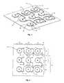
- FIG. 1is a perspective view of an antenna system embodying features of the present invention.
- FIG. 2is a front plan view of the system of FIG. 1 .
- FIG. 3is a side elevation view of the system of FIG. 1 .
- FIG. 4is an enlarged top plan view of a column of radiating elements of the system of FIG. 1 .
- the antenna system of the present inventionincludes a substantially planar ground plane 11 , an aperture array 12 of patch radiating elements 14 , a monolithic or single layer feed structure 15 , and radio frequency (RF) first and second connectors 16 and 17 .
- the first and second connectors 16 and 17provide for connection of the antenna system to wireless devices.
- the aperture array 12 and the feed structure 15are spaced a substantially uniform distance from the ground plane 11 .
- the ground plane 11is square
- the aperture array 12is a three by three array with first, second, and third rows 20 , 21 and 22 , and first, second and third columns 25 , 26 , 27 .
- Other ground plane shapes and other array sizescan be used with the present invention.
- the ground plane 11 , radiating elements 14 , and feed structure 14are preferably made of sheet aluminum and have a size and shaped dictated by a particular application.
- Other highly conductive sheet metal materialssuch as copper and brass can also be used. These materials can be formed by being stamped, laser cut or printed/etched on an RF compatible substrate.
- the radiating elements 14 shownare air-loaded microstrip stacked patch antenna elements, each including an octagonal driver patch 30 spaced from the ground plane 11 by a first spacer 31 , and a round parasitic patch 32 spaced from the driver patch 30 , opposite the ground plane 11 , by a second spacer 33 .
- the octagonal driver patches 30are oriented with two spaced opposed horizontal, vertical, 45 degrees and ⁇ 45 degrees edges each.
- each radiating element 14is attached to the ground plane 11 by a threaded PEM stud 34 that is pressed into the ground plane 11 and extends through the centers of the first spacer 31 , the driver patch 30 , the second spacer 33 and the parasitic patch 32 , with a nut 35 threading onto stud 34 over the parasitic patch 32 .
- Other fastener typescan be used such as clips, rivets, welds and crimping.
- the first and second spacers 31 and 33can be separate individual parts or can be integral to the driver patch 30 and parasitic patch 32 .
- the illustrated embodimentuses separate aluminum spacers but non-metallic spacers could also be used.
- the first connector 16is mounted on the ground plane 11 on the-side opposite the aperture array 12 , and is located between the first row 20 and the second row 21 and between the second column 26 and the third column 27 .
- the first connector 16includes a first connector pin 37 that extends through a relief hole in the ground plane 11 toward the aperture array 12 .
- the second connector 17is mounted on the ground plane 11 on the side opposite the aperture array 12 , and is located between the second row 21 and the third row 22 and between the second column 26 and the third column 27 .
- the second connector 17includes a second connector pin 38 that extends through a relief hole in the ground plane 11 toward the aperture array 12 .
- the feed structure 15 shownincludes an air-loaded microstrip transmission line first beam forming network 40 and an air-loaded microstrip transmission line second beam forming network 41 , that are each substantially co-planar with the driver patches 30 .
- the first and second beam forming networks 40 and 41are operative-for transferring RF energy between the radiating elements 14 and the first and second connectors 16 and 17 , respectively.
- the first and second beam forming networks 40 and 41also function as RF combiners/dividers.
- the first beam forming network 40connects to the first connector pin 37 and includes a pair of transmission line first primary sections 43 that extend outwardly in a substantially horizontal direction on either side from the first connector pin 37 .
- First secondary sections 44connect to the first primary sections 43 at the first connector pin 37 and at the outer ends of the first primary sections 43 , and extend upwardly and downwardly therefrom.
- a first coupling section 46connects to the end of each of the six first secondary sections 44 opposite the end connected to a first primary section 43 .
- Each of the six first coupling sections 46connects at a first angle of 45 degrees to the upper, right edge of the driver patch 30 of one of the radiating elements 14 of the first and second rows 20 and 21 .
- the first beam forming network 40 and the radiating elements 14 of the first and second rows 20 and 21form a two by three first antenna array 47 with a 45 degree polarization.
- the second beam forming network 41connects to the second connector pin 38 and includes a pair of transmission line second primary sections 49 that extend outwardly in a substantially horizontal direction on either side from the second connector pin 38 .
- Second secondary sections 50connect to the second primary sections 49 at the second connector pin 38 and at the outer ends of the second primary sections 49 , and extend upwardly and downwardly therefrom.
- a second coupling section 51connects to the end of each of the six second secondary sections 50 opposite the end connected to a second primary section 49 .
- Each of the six second coupling sections 51connects at a second angle of 135 degrees to the lower, right edge of the driver patch 30 of one of the radiating elements 14 of the second and third rows 21 and 22 .
- the second beam forming network 41 and the radiating elements 14 of the second and third rows 21 and 22form a two by three second antenna array 53 with a ⁇ 45 degree polarization.
- the radiating elements 14 of the aperture array 12are partially shared by the first and second antenna arrays 47 and 54 .
- the radiating elements 14 of the first row 20are unshared and have a 45 degree polarization.
- the radiating elements 14 of the second row 21are shared and have a dual slant ⁇ 45 degree polarization.
- the radiating elements 14 of the third row 20are unshared and have a ⁇ 45 degree polarization.
- the present inventionmay be applied by using various RF transmission line and element technologies.
- the first and second antenna arrays 47 and 54operate on the same frequency band.
- the radiating elements 14can also be configured to operate the first and second antenna arrays 47 and 54 across different frequency bands, creating a dual frequency band antenna system.
- the dual polarization characteristic of the aperture array 12does not have to be linear, as in the illustrated embodiment, but can be of other combinations such as left and right hand circular polarization. Angles other than the shown ⁇ 45 degrees, such as 0 and 90 degrees, may be used. More than two arrays can be partially shared while using the same aperture. Array sizes and shapes other than the three by three square array shown may be used.
- the antenna system of the present inventionprovides a reduced aperture area and fewer radiating elements than unshared antenna systems.
- the antenna system of the present inventionallows larger arrays than the prior known fully shared systems while providing less complex and shorter beam forming networks.
- the present inventionfurther provides greater flexibility in the layout of the beam forming networks of the aperture.
Landscapes
- Variable-Direction Aerials And Aerial Arrays (AREA)
- Waveguide Aerials (AREA)
Abstract
Description
Claims (9)
Priority Applications (1)
| Application Number | Priority Date | Filing Date | Title |
|---|---|---|---|
| US10/408,334US6788258B2 (en) | 2002-04-09 | 2003-04-07 | Partially shared antenna aperture |
Applications Claiming Priority (2)
| Application Number | Priority Date | Filing Date | Title |
|---|---|---|---|
| US37120102P | 2002-04-09 | 2002-04-09 | |
| US10/408,334US6788258B2 (en) | 2002-04-09 | 2003-04-07 | Partially shared antenna aperture |
Publications (2)
| Publication Number | Publication Date |
|---|---|
| US20030189516A1 US20030189516A1 (en) | 2003-10-09 |
| US6788258B2true US6788258B2 (en) | 2004-09-07 |
Family
ID=28678392
Family Applications (1)
| Application Number | Title | Priority Date | Filing Date |
|---|---|---|---|
| US10/408,334Expired - Fee RelatedUS6788258B2 (en) | 2002-04-09 | 2003-04-07 | Partially shared antenna aperture |
Country Status (1)
| Country | Link |
|---|---|
| US (1) | US6788258B2 (en) |
Cited By (16)
| Publication number | Priority date | Publication date | Assignee | Title |
|---|---|---|---|---|
| US20050099358A1 (en)* | 2002-11-08 | 2005-05-12 | Kvh Industries, Inc. | Feed network and method for an offset stacked patch antenna array |
| US20050110695A1 (en)* | 2003-11-22 | 2005-05-26 | Young-Bae Jung | Horn antenna for circular polarization using planar radiator |
| US20060041326A1 (en)* | 2001-07-13 | 2006-02-23 | Volker Kreidler | Method and system for the electronic provision of services for machines via a data communication link |
| US20060092078A1 (en)* | 2004-11-02 | 2006-05-04 | Calamp Corporate | Antenna systems for widely-spaced frequency bands of wireless communication networks |
| US7102571B2 (en) | 2002-11-08 | 2006-09-05 | Kvh Industries, Inc. | Offset stacked patch antenna and method |
| US20070129826A1 (en)* | 2001-07-13 | 2007-06-07 | Volker Kreidler | System architecture and method for network-delivered automation-related content |
| US20080136713A1 (en)* | 2006-12-08 | 2008-06-12 | Advanced Connectek Inc. | Antenna array |
| US20110298665A1 (en)* | 2010-06-07 | 2011-12-08 | Joymax Electronics Co., Ltd. | Array antenna device |
| US8219451B2 (en) | 2001-07-13 | 2012-07-10 | Siemens Aktiengesellschaft | System and method for electronic delivery of content for industrial automation systems |
| US8768716B2 (en) | 2001-07-13 | 2014-07-01 | Siemens Aktiengesellschaft | Database system and method for industrial automation services |
| US20160006132A1 (en)* | 2014-07-04 | 2016-01-07 | Lite-On Electronics (Guangzhou) Limited | Dual-feed dual-polarization high directivity array antenna system |
| CN104332713B (en)* | 2014-11-14 | 2017-03-15 | 南京理工大学 | Monolayer double frequency round polarized micro-strip array antenna |
| US10978812B2 (en) | 2016-10-17 | 2021-04-13 | Director General, Defence Research & Development Organisation (Drdo) | Single layer shared aperture dual band antenna |
| WO2021164061A1 (en)* | 2020-02-19 | 2021-08-26 | 瑞声声学科技(深圳)有限公司 | Antenna oscillator and antenna |
| US20220200162A1 (en)* | 2018-05-15 | 2022-06-23 | Anokiwave, Inc. | Cross-polarized time division duplexed antenna |
| US11742593B2 (en)* | 2021-09-01 | 2023-08-29 | Communication Components Antenna Inc. | Wideband bisector anntenna array with sectional sharing for left and right beams |
Families Citing this family (27)
| Publication number | Priority date | Publication date | Assignee | Title |
|---|---|---|---|---|
| WO2008030208A2 (en)* | 2005-06-29 | 2008-03-13 | Georgia Tech Research Corporation | Multilayer electronic component systems and methods of manufacture |
| ES2380580T3 (en) | 2005-10-14 | 2012-05-16 | Fractus S.A. | Small triple band antenna training for cellular base stations |
| TW200929693A (en)* | 2007-12-28 | 2009-07-01 | Advanced Connectek Inc | Assembled-type antenna array |
| US8599072B2 (en)* | 2008-06-10 | 2013-12-03 | Apple Inc. | Antennas |
| TWI385858B (en)* | 2008-09-26 | 2013-02-11 | Advanced Connectek Inc | Array antenna |
| US9496620B2 (en) | 2013-02-04 | 2016-11-15 | Ubiquiti Networks, Inc. | Radio system for long-range high-speed wireless communication |
| US8836601B2 (en) | 2013-02-04 | 2014-09-16 | Ubiquiti Networks, Inc. | Dual receiver/transmitter radio devices with choke |
| EP2472670A4 (en)* | 2009-08-25 | 2014-06-18 | Nec Corp | Antenna device |
| DE102009058846A1 (en)* | 2009-12-18 | 2011-06-22 | Kathrein-Werke KG, 83022 | Dual polarized group antenna, in particular mobile radio antenna |
| US8416142B2 (en)* | 2009-12-18 | 2013-04-09 | Kathrein-Werke Kg | Dual-polarized group antenna |
| US9397820B2 (en) | 2013-02-04 | 2016-07-19 | Ubiquiti Networks, Inc. | Agile duplexing wireless radio devices |
| US9543635B2 (en) | 2013-02-04 | 2017-01-10 | Ubiquiti Networks, Inc. | Operation of radio devices for long-range high-speed wireless communication |
| US9293817B2 (en) | 2013-02-08 | 2016-03-22 | Ubiquiti Networks, Inc. | Stacked array antennas for high-speed wireless communication |
| CN103165988A (en)* | 2013-03-13 | 2013-06-19 | 电子科技大学 | Broadband Circularly Polarized RFID Reader Antenna |
| PL3648359T3 (en) | 2013-10-11 | 2025-03-31 | Ubiquiti Inc. | Wireless radio system optimization by persistent spectrum analysis |
| US10942262B2 (en)* | 2014-02-12 | 2021-03-09 | Battelle Memorial Institute | Shared aperture antenna array |
| LT3114884T (en) | 2014-03-07 | 2020-02-10 | Ubiquiti Inc. | IDENTIFICATION AND AUTHENTICATION OF THE CIRCULAR DEVICE |
| WO2015134755A2 (en) | 2014-03-07 | 2015-09-11 | Ubiquiti Networks, Inc. | Devices and methods for networked living and work spaces |
| EP3120642B1 (en) | 2014-03-17 | 2023-06-07 | Ubiquiti Inc. | Array antennas having a plurality of directional beams |
| WO2015153717A1 (en) | 2014-04-01 | 2015-10-08 | Ubiquiti Networks, Inc. | Antenna assembly |
| US9735475B2 (en)* | 2014-12-01 | 2017-08-15 | Anderson Contract Engineering, Inc. | Low cost antenna array and methods of manufacture |
| JP6899942B2 (en)* | 2016-09-23 | 2021-07-07 | 日本ピラー工業株式会社 | Planar antenna and antenna device |
| CN107896129B (en)* | 2017-11-16 | 2020-07-24 | 哈尔滨工程大学 | Dimensionality reduction optimization algorithm for sparse concentric circular array |
| EP4143993A4 (en)* | 2020-05-01 | 2024-07-24 | Fleet Space Technologies Pty Ltd | LEO SATELLITE COMMUNICATION SYSTEMS AND METHODS |
| TWM610584U (en)* | 2021-01-08 | 2021-04-11 | 佳邦科技股份有限公司 | Array type antenna module |
| JP7260213B1 (en) | 2022-03-24 | 2023-04-18 | 株式会社光電製作所 | Antenna device, method for manufacturing antenna device |
| CN120033448A (en)* | 2023-11-22 | 2025-05-23 | 华为技术有限公司 | Antenna unit and communication equipment |
Citations (8)
| Publication number | Priority date | Publication date | Assignee | Title |
|---|---|---|---|---|
| US4464663A (en) | 1981-11-19 | 1984-08-07 | Ball Corporation | Dual polarized, high efficiency microstrip antenna |
| US5554995A (en)* | 1991-09-16 | 1996-09-10 | Goldstar Co., Ltd. | Flat antenna of a dual feeding type |
| US6002370A (en)* | 1998-08-11 | 1999-12-14 | Northern Telecom Limited | Antenna arrangement |
| US6121929A (en) | 1997-06-30 | 2000-09-19 | Ball Aerospace & Technologies Corp. | Antenna system |
| US6288677B1 (en) | 1999-11-23 | 2001-09-11 | The United States Of America As Represented By The Administrator Of The National Aeronautics And Space Administration | Microstrip patch antenna and method |
| US6359588B1 (en) | 1997-07-11 | 2002-03-19 | Nortel Networks Limited | Patch antenna |
| US6621456B2 (en)* | 2001-10-19 | 2003-09-16 | The United States Of America As Represented By The Secretary Of The Navy | Multipurpose microstrip antenna for use on missile |
| US6700542B2 (en)* | 2001-10-19 | 2004-03-02 | B.E.A.S.A. | Planar antenna |
- 2003
- 2003-04-07USUS10/408,334patent/US6788258B2/ennot_activeExpired - Fee Related
Patent Citations (8)
| Publication number | Priority date | Publication date | Assignee | Title |
|---|---|---|---|---|
| US4464663A (en) | 1981-11-19 | 1984-08-07 | Ball Corporation | Dual polarized, high efficiency microstrip antenna |
| US5554995A (en)* | 1991-09-16 | 1996-09-10 | Goldstar Co., Ltd. | Flat antenna of a dual feeding type |
| US6121929A (en) | 1997-06-30 | 2000-09-19 | Ball Aerospace & Technologies Corp. | Antenna system |
| US6359588B1 (en) | 1997-07-11 | 2002-03-19 | Nortel Networks Limited | Patch antenna |
| US6002370A (en)* | 1998-08-11 | 1999-12-14 | Northern Telecom Limited | Antenna arrangement |
| US6288677B1 (en) | 1999-11-23 | 2001-09-11 | The United States Of America As Represented By The Administrator Of The National Aeronautics And Space Administration | Microstrip patch antenna and method |
| US6621456B2 (en)* | 2001-10-19 | 2003-09-16 | The United States Of America As Represented By The Secretary Of The Navy | Multipurpose microstrip antenna for use on missile |
| US6700542B2 (en)* | 2001-10-19 | 2004-03-02 | B.E.A.S.A. | Planar antenna |
Cited By (22)
| Publication number | Priority date | Publication date | Assignee | Title |
|---|---|---|---|---|
| US7567853B2 (en) | 2001-07-13 | 2009-07-28 | Siemens Aktiengesellschaft | Method and system for the electronic provision of services for machines via a data communication link |
| US8219451B2 (en) | 2001-07-13 | 2012-07-10 | Siemens Aktiengesellschaft | System and method for electronic delivery of content for industrial automation systems |
| US20060041326A1 (en)* | 2001-07-13 | 2006-02-23 | Volker Kreidler | Method and system for the electronic provision of services for machines via a data communication link |
| US7127322B2 (en) | 2001-07-13 | 2006-10-24 | Siemens Aktiengesellschaft | Method and system for the electronic provision of services for machines via a data communication link |
| US20070093929A1 (en)* | 2001-07-13 | 2007-04-26 | Volker Kreidler | Method and system for the electronic provision of services for machines via a data communication link |
| US20070129826A1 (en)* | 2001-07-13 | 2007-06-07 | Volker Kreidler | System architecture and method for network-delivered automation-related content |
| US8768716B2 (en) | 2001-07-13 | 2014-07-01 | Siemens Aktiengesellschaft | Database system and method for industrial automation services |
| US7102571B2 (en) | 2002-11-08 | 2006-09-05 | Kvh Industries, Inc. | Offset stacked patch antenna and method |
| US20050099358A1 (en)* | 2002-11-08 | 2005-05-12 | Kvh Industries, Inc. | Feed network and method for an offset stacked patch antenna array |
| US7212162B2 (en)* | 2003-11-22 | 2007-05-01 | Electronics And Telecommunications Research Institute | Horn antenna for circular polarization using planar radiator |
| US20050110695A1 (en)* | 2003-11-22 | 2005-05-26 | Young-Bae Jung | Horn antenna for circular polarization using planar radiator |
| US20060092078A1 (en)* | 2004-11-02 | 2006-05-04 | Calamp Corporate | Antenna systems for widely-spaced frequency bands of wireless communication networks |
| US7616159B2 (en)* | 2006-12-08 | 2009-11-10 | Advanced Connectek Inc. | Antenna array |
| US20080136713A1 (en)* | 2006-12-08 | 2008-06-12 | Advanced Connectek Inc. | Antenna array |
| US20110298665A1 (en)* | 2010-06-07 | 2011-12-08 | Joymax Electronics Co., Ltd. | Array antenna device |
| US20160006132A1 (en)* | 2014-07-04 | 2016-01-07 | Lite-On Electronics (Guangzhou) Limited | Dual-feed dual-polarization high directivity array antenna system |
| CN104332713B (en)* | 2014-11-14 | 2017-03-15 | 南京理工大学 | Monolayer double frequency round polarized micro-strip array antenna |
| US10978812B2 (en) | 2016-10-17 | 2021-04-13 | Director General, Defence Research & Development Organisation (Drdo) | Single layer shared aperture dual band antenna |
| US20220200162A1 (en)* | 2018-05-15 | 2022-06-23 | Anokiwave, Inc. | Cross-polarized time division duplexed antenna |
| US11695216B2 (en)* | 2018-05-15 | 2023-07-04 | Anokiwave, Inc. | Cross-polarized time division duplexed antenna |
| WO2021164061A1 (en)* | 2020-02-19 | 2021-08-26 | 瑞声声学科技(深圳)有限公司 | Antenna oscillator and antenna |
| US11742593B2 (en)* | 2021-09-01 | 2023-08-29 | Communication Components Antenna Inc. | Wideband bisector anntenna array with sectional sharing for left and right beams |
Also Published As
| Publication number | Publication date |
|---|---|
| US20030189516A1 (en) | 2003-10-09 |
Similar Documents
| Publication | Publication Date | Title |
|---|---|---|
| US6788258B2 (en) | Partially shared antenna aperture | |
| US6121929A (en) | Antenna system | |
| US7064729B2 (en) | Omni-dualband antenna and system | |
| CA2594683C (en) | Array antenna including a monolithic antenna feed assembly and related methods | |
| US7403169B2 (en) | Antenna device and array antenna | |
| EP1444753B1 (en) | Patch fed printed antenna | |
| US7692601B2 (en) | Dipole antennas and coaxial to microstrip transitions | |
| US9735475B2 (en) | Low cost antenna array and methods of manufacture | |
| US12119556B2 (en) | Base station antennas having high directivity radiating elements with balanced feed networks | |
| EP1997186B1 (en) | Broadband single vertical polarized base station antenna | |
| US10333228B2 (en) | Low coupling 2×2 MIMO array | |
| JPS621304A (en) | Microstrip antenna array and manufacture thereof | |
| US6061032A (en) | Device in antenna units | |
| US11264730B2 (en) | Quad-port radiating element | |
| US20150002356A1 (en) | Tube and ring directional end-fire array antenna | |
| US11563271B2 (en) | Antenna array with ABFN circuitry | |
| US9077083B1 (en) | Dual-polarized array antenna | |
| US4912482A (en) | Antenna | |
| CN113659312A (en) | Base station antenna with low cost metal plate crossed dipole radiating elements | |
| EP2005522B1 (en) | Broadband dual polarized base station antenna | |
| US20030227420A1 (en) | Integrated aperture and calibration feed for adaptive beamforming systems | |
| AU740174B2 (en) | Antenna having double-sided printed circuit board with collinear, alternating and opposing radiating elements and microstrip transmission line | |
| US20240154296A1 (en) | Base station antennas with parallel feed boards | |
| JPH0661738A (en) | Plane antenna |
Legal Events
| Date | Code | Title | Description |
|---|---|---|---|
| AS | Assignment | Owner name:ARC WIRELESS SOLUTIONS, INC., COLORADO Free format text:ASSIGNMENT OF ASSIGNORS INTEREST;ASSIGNOR:OLSON, STEVEN C.;REEL/FRAME:013956/0092 Effective date:20030402 | |
| FPAY | Fee payment | Year of fee payment:4 | |
| FPAY | Fee payment | Year of fee payment:8 | |
| AS | Assignment | Owner name:ARC GROUP WORLDWIDE, INC., FLORIDA Free format text:CHANGE OF NAME;ASSIGNOR:ARC WIRELESS SOLUTIONS, INC.;REEL/FRAME:032712/0668 Effective date:20120807 Owner name:RBS CITIZENS, N.A., MASSACHUSETTS Free format text:SECURITY INTEREST;ASSIGNORS:ARC GROUP WORLDWIDE, INC.;FLOMET LLC;TEKNA SEAL LLC;REEL/FRAME:032695/0878 Effective date:20140407 | |
| AS | Assignment | Owner name:ARC WIRELESS, INC., FLORIDA Free format text:ASSIGNMENT OF ASSIGNORS INTEREST;ASSIGNOR:ARC GROUP WORLDWIDE, INC.;REEL/FRAME:032760/0180 Effective date:20140424 | |
| AS | Assignment | Owner name:RBS CITIZENS, N.A., MASSACHUSETTS Free format text:SECURITY INTEREST;ASSIGNOR:ARC WIRELESS, INC.;REEL/FRAME:032839/0130 Effective date:20140424 | |
| REMI | Maintenance fee reminder mailed | ||
| LAPS | Lapse for failure to pay maintenance fees | ||
| STCH | Information on status: patent discontinuation | Free format text:PATENT EXPIRED DUE TO NONPAYMENT OF MAINTENANCE FEES UNDER 37 CFR 1.362 | |
| FP | Lapsed due to failure to pay maintenance fee | Effective date:20160907 | |
| AS | Assignment | Owner name:TEKNA SEAL LLC, CONNECTICUT Free format text:RELEASE BY SECURED PARTY;ASSIGNOR:CITIZENS BANK, N.A., AS SUCCESSOR TO RBS CITIZENS, N.A.;REEL/FRAME:051495/0763 Effective date:20191227 Owner name:FLOMET LLC, FLORIDA Free format text:RELEASE BY SECURED PARTY;ASSIGNOR:CITIZENS BANK, N.A., AS SUCCESSOR TO RBS CITIZENS, N.A.;REEL/FRAME:051495/0763 Effective date:20191227 Owner name:ARC WIRELESS, INC., FLORIDA Free format text:RELEASE BY SECURED PARTY;ASSIGNOR:CITIZENS BANK, N.A., AS SUCCESSOR TO RBS CITIZENS, N.A.;REEL/FRAME:051495/0924 Effective date:20191227 Owner name:ARC GROUP WORLDWIDE, INC., FLORIDA Free format text:RELEASE BY SECURED PARTY;ASSIGNOR:CITIZENS BANK, N.A., AS SUCCESSOR TO RBS CITIZENS, N.A.;REEL/FRAME:051495/0763 Effective date:20191227 |