US6788024B2 - Position-sensorless motor control method and apparatus - Google Patents
Position-sensorless motor control method and apparatusDownload PDFInfo
- Publication number
- US6788024B2 US6788024B2US10/390,148US39014803AUS6788024B2US 6788024 B2US6788024 B2US 6788024B2US 39014803 AUS39014803 AUS 39014803AUS 6788024 B2US6788024 B2US 6788024B2
- Authority
- US
- United States
- Prior art keywords
- motor
- inductance
- detected
- current
- current fluctuation
- Prior art date
- Legal status (The legal status is an assumption and is not a legal conclusion. Google has not performed a legal analysis and makes no representation as to the accuracy of the status listed.)
- Expired - Lifetime
Links
Images


Classifications
- H—ELECTRICITY
- H02—GENERATION; CONVERSION OR DISTRIBUTION OF ELECTRIC POWER
- H02P—CONTROL OR REGULATION OF ELECTRIC MOTORS, ELECTRIC GENERATORS OR DYNAMO-ELECTRIC CONVERTERS; CONTROLLING TRANSFORMERS, REACTORS OR CHOKE COILS
- H02P6/00—Arrangements for controlling synchronous motors or other dynamo-electric motors using electronic commutation dependent on the rotor position; Electronic commutators therefor
- H02P6/14—Electronic commutators
- H02P6/16—Circuit arrangements for detecting position
- H—ELECTRICITY
- H02—GENERATION; CONVERSION OR DISTRIBUTION OF ELECTRIC POWER
- H02P—CONTROL OR REGULATION OF ELECTRIC MOTORS, ELECTRIC GENERATORS OR DYNAMO-ELECTRIC CONVERTERS; CONTROLLING TRANSFORMERS, REACTORS OR CHOKE COILS
- H02P21/00—Arrangements or methods for the control of electric machines by vector control, e.g. by control of field orientation
- H02P21/14—Estimation or adaptation of machine parameters, e.g. flux, current or voltage
- H02P21/16—Estimation of constants, e.g. the rotor time constant
Definitions
- the present inventionrelates to an AC (alternating current) motor control apparatus and specifically to a position-sensorless motor control method and apparatus that estimates and detects a magnetic pole position of a synchronous motor's rotor without needing a sensor thereby controlling the AC motor.
- ACalternating current
- Patent document 1Japanese Application Patent Laid-open Publication No. Hei 07-245981;
- Patent document 2Japanese Application Patent Laid-open Publication No. Hei 08-149898.
- synchronous motorscan be classified into two types: cylindrical types and salient-pole types (Ld ⁇ Lq; Ld denotes inductance in the d-axis direction and Lq denotes inductance in the q-axis direction).
- a salient-pole synchronous motor's magnetic pole position estimation methodincludes a method that uses voltage induced by the motor and a method that uses the motor's salient-pole property.
- the prior artincludes the patent document 1.
- This publicationdiscloses a rotor position detection system that applies an alternating current voltage to a motor and separates the generated motor current into the parallel component direction and the perpendicular component direction to the alternating current voltage thereby detecting the rotor position based on the motor current components of at least one direction.
- the prior artalso includes the patent document 2.
- a primary winding's leakage inductancechanges by influence of magnetic saturation in the teeth. Therefore, the technology disclosed in this document superimposes an alternating current voltage other than the fundamental wave component, measures the inductance of the winding based on the relation between the current's flow and the alternating current voltage, and then estimates magnetic flux from the inductance fluctuation.
- This documentsdescribes the control of an inverter's output voltage and current according to the estimated magnetic flux.
- the above prior artis theoretical based on the motor's salient-pole characteristic and provides an effective system that can accurately estimate a magnetic pole position by inputting the motor current.
- the above prior artuses the characteristic that when an alternating current voltage is applied to a salient-pole motor, a current is also generated in the direction perpendicular to the alternating current voltage application vector when the application vector is not parallel to or perpendicular to the magnetic flux direction (d-axis). Therefore, by using the above characteristic, it is possible to estimate and detect the rotor position (magnetic pole position) using the salient-pole property in the area where motor current is relatively light and does not cause magnetic saturation.
- an object of the present inventionis to provide a motor control method and apparatus which has a position estimation means that can accurately and reliably estimate the rotor position even when local magnetic saturation occurs in the motor current direction due to heavy current.
- the above-mentioned methodapplies voltage in the pre-determined direction to the AC motor's current vector direction to detect the rotor position, detects the current fluctuation condition caused by the applied voltage, detects inductance based on the detected current fluctuation condition, estimates and detects the AC motor's rotor position by using the detected inductance, thereby performing vector control of the AC motor.
- the controllerdetects inductance in the direction perpendicular to the AC motor's current vector direction within the range determined in terms of detection accuracy of the motor's rotor position, estimates and detects the AC motor's rotor position based on the detected inductance, thereby performing vector control of the AC motor.
- the above-mentioned methodapplies voltage in the pre-determined direction to the AC motor's current vector direction to detect the rotor position, detects the current fluctuation condition caused by the applied voltage, calculates inductance based on the detected current fluctuation condition, estimates and detects the AC motor's rotor position, thereby performing vector control of the AC motor.
- the above-mentioned methodestimates and detects the AC motor's rotor position based on the difference between the detected current fluctuation condition and the reference current fluctuation condition calculated from the torque command and rotation speed, thereby performing vector control of the AC motor.
- this methodis a position-sensorless motor control method wherein the pre-determined direction to the AC motor's current vector direction is the direction perpendicular to the current vector direction.
- a motor control apparatuscomprising a PWM inverter for applying voltage to a salient-pole AC motor and a controller for controlling the PWM inverter, wherein the controller comprises a means for applying a position detection voltage signal in the pre-determined direction to the AC motor's detected current vector direction and detecting the current fluctuation condition caused by the position detection voltage, a means for detecting the motor inductance from the detected current fluctuation, and a position estimation means for estimating the AC motor's rotor position based on the detected motor inductance, thereby performing vector control of the AC motor.
- the above-mentioned apparatuscomprises a position estimation means for estimating and detecting the AC motor's rotor position based on the detected motor inductance and the reference inductance determined by the torque command and motor speed.
- the pre-determined directionis the direction perpendicular to the current vector direction.
- the above-mentioned apparatuscomprises a position estimation means for estimating the AC motor's rotor position based on the difference between the current fluctuation condition caused by the position detection voltage and the reference current fluctuation condition calculated from the torque command and rotation speed.
- the above-mentioned apparatuscorrects the reference current fluctuation condition according to the magnitude of the input voltage of the PWM inverter.
- the above-mentioned apparatuscorrects the reference current fluctuation condition according to the operating point of the AC motor.
- the above-mentioned apparatusmakes the reference current fluctuation condition into a table for each operating point of the AC motor or a table according to the magnitude of the PWM inverter's input voltage and stores the table in the controller.
- a motor control apparatuscomprising a PWM inverter for applying voltage to a salient-pole AC motor and a controller for controlling the PWM inverter, wherein the controller comprises a position estimation means for detecting motor inductance in the direction 45 degrees to the magnetic flux axis and estimating the AC motor's rotor position based on the detected motor inductance.
- the above-mentioned apparatuscomprises a position estimation means for estimating the AC motor's rotor position based on the current fluctuation condition detected by applying a position detection voltage signal in the direction 45 degrees to the magnetic flux axis.
- the above-mentioned apparatuscomprises a position estimation means for estimating the AC motor's rotor position based on the difference between the detected current fluctuation condition and the reference current fluctuation condition.
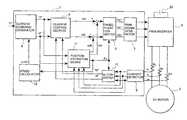
- FIG. 1is a schematic diagram that illustrates a motor control apparatus which is a first embodiment of the present invention.
- FIG. 2shows the relation between the rotating coordinate system (d- and q-axes) and the coordinate system at rest ( ⁇ - ⁇ axes).
- FIG. 3shows the inductance characteristic of the motor.
- FIG. 4shows the inductance distribution when magnetic saturation occurs in the motor current vector direction.
- FIG. 5shows a configuration example of a magnetic pole position estimation means that uses inductance.
- FIG. 6shows an example of a detection method that uses current fluctuation ⁇ i which is a configuration example of a magnetic pole position estimation means.
- FIG. 7shows a configuration example in which the rotor position is obtained based on inductance.
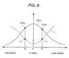
- FIG. 8shows the relation among the deviation from the direction perpendicular to the current vector I, detection accuracy, and current fluctuation sensitivity.
- FIG. 1is a schematic diagram that illustrates a motor control apparatus which is a first embodiment of the present invention.
- a controller 1inputs torque command Tr* and outputs a signal sent by a PWM signal generator 7 to a PWM inverter 3 so that an AC motor 2 can generate torque specified by the command.
- a current command generator 4located in the controller 1 inputs torque command Tr* and motor speed ⁇ m ⁇ circumflex over ( ) ⁇ to determine the current commands iq* and id* so that maximum efficiency can be obtained at the current operating point.
- id*denotes a current command for the direction (d-axis) of the motor rotor's magnetic flux
- iq*denotes a current command for the direction (q-axis) perpendicular to the motor rotor's magnetic flux direction.
- the above-mentioned d- and q-axis coordinatesare rotating coordinate systems as shown in FIG. 2 .
- the coordinate systemsrotate at motor angular speed ⁇ to the coordinate system at rest ⁇ - ⁇ axes (two-phase coordinates converted from U, V, and W phases).
- the phase from the reference ⁇ -axis towards the direction (d-axis) of the motor rotor's magnetic fluxbe rotor position (magnetic pole position) ⁇ .
- a current control section 5performs current control calculation on the rotating coordinate d- and q-axes to determine voltage commands Vdc and Vqc on the d- and q-axes.
- the current control of the d- and q-axis coordinatesmakes it possible to accurately control both the magnetic flux direction current and the current (acting on torque) perpendicular to the magnetic flux direction current, thereby enabling control of the motor torque and magnetic flux.
- a three-phase converter 6performs coordinate transformation from the d- and q-axes to the U, V, and W phases to obtain three-phase alternating current voltage commands Vu*, Vv*, and Vw*.
- a PWM signal generator 7converts the alternating current voltage command signals Vu*, Vv*, and Vw* into PWM signals to apply them to the PWM inverter 3 .
- a current detector 9 located in the controller 1imports motor currents iu, iv, and iw detected by three-phase current sensors 8 u , 8 v , and 8 w , and a dq converter 10 calculates currents id ⁇ circumflex over ( ) ⁇ and iq ⁇ circumflex over ( ) ⁇ detected on the d- and q-axes and then feeds the result back to the current control section 5 .
- the aboveis the configuration of the motor control system and is also a control method, generally called “vector control”.
- Coordinate transformation formulas used in the three-phase converter 6 and the dq converter 10are expressed by Equations 1 and 2.
- the formeris a calculation formula that converts (three-phase converter 6 ) d- and q-axis voltages Vd* and Vq* into three-phase voltages Vu*, Vv*, and Vw*
- the latteris a calculation formula that converts (dq converter 10 ) three-phase currents iu, iv, and iw into d- and q-axis currents iq ⁇ circumflex over ( ) ⁇ and id ⁇ circumflex over ( ) ⁇ .
- coordinate transformationrequires rotor position ⁇ ( ⁇ C).
- ⁇ Crotor position
- ⁇ Cposition-sensor
- an induced voltage based methodis applied to the motor's high and medium speed range where induced voltage can be detected (estimated).
- a method that utilizes the motor's salient-pole property(Ld ⁇ Lq) is applied to the motor's stop and low speed range where induced voltage is not easily detected.
- Lddenotes the d-axis direction inductance
- Lqdenotes the q-axis direction inductance
- reverse salient-pole propertyThe characteristic of the inductance of a reverse salient-pole motor is shown in FIG. 3 as an example.
- FIG. 3shows the magnitude of the inductance on the d- and q-axis directions (the distance from the ellipse center 0 to the circumference indicates the magnitude of the inductance).
- the magnetic flux direction inductance Ldbecomes minimized and the inductance Lq in the direction perpendicular to the magnetic flux direction becomes maximized.
- a magnetic pole position detection voltage signalis applied (superimposed) to the motor, fluctuation of the generated motor current is detected, and the inductance is measured.
- the direction in which thus measured inductance becomes minimizedis the rotor's magnetic flux direction (magnetic pole position).
- the above position estimation and detection by using a salient-pole propertycan be performed only when the motor's inductance characteristic is as shown in FIG. 3 . That is the case when rotor's magnetic flux direction (d-axis) inductance or inductance of the direction (q-axis) perpendicular to the magnetic flux direction is minimized (or maximized) even though magnetic saturation occurs due to the current.
- d-axismagnetic flux direction
- q-axisdirection perpendicular to the magnetic flux direction
- FIG. 4shows the inductance distribution in such a case.
- Irepresents the current vector.
- the current vector Icauses magnetic saturation, which minimizes the direction's inductance. If a position estimation method based on the above-mentioned salient-pole property is applied when such a characteristic is occurring, the estimated position is not in the d-axis direction, but in the current vector direction. As a result, it may not be possible to accurately estimate the magnetic pole position.
- a magnetic pole position detection (estimate) methodis applied in such a situation.
- the basic concept of the methodis to detect inductance in the direction where no magnetic saturation has occurred and to detect (estimate) the rotor's position based on the inductance. For example, if current vector I has caused magnetic saturation, which greatly decreases the inductance in that direction, the direction that is least affected by the magnetic saturation is the direction perpendicular to the current vector I (Y direction in FIG. 4 ).
- the inductance of this Y-axis direction(direction perpendicular to the current vector) is the motor inductance that is not affected by magnetic saturation and changes according to the motor's rotor position. Therefore, measuring inductance of the direction perpendicular to the current vector I by using this characteristic makes it possible to estimate the current rotor position.
- a position estimation means 11detects (estimates) the rotor position.
- the position estimation means 11outputs the position detection value ⁇ c that is applicable to coordinate transformation calculations in the three-phase converter 6 and the d-q converter 10 . Furthermore, motor speed ⁇ m ⁇ circumflex over ( ) ⁇ can be obtained by calculating the rate of change over time of the position detection value ⁇ c by using a speed calculator 12 .
- the position estimation means 11outputs the position detection value ⁇ c to use it for the coordinate transformation calculations in the three-phase converter 6 and the dq converter 10 . Furthermore, motor speed ⁇ m ⁇ circumflex over ( ) ⁇ can be obtained by calculating the rate of change over time of the position detection value ⁇ c by using a speed calculator 12 .
- the aboveis the basic configuration and operations of the position-sensorless control system when heavy current causes magnetic saturation in the current vector direction.
- FIG. 5illustrates an example of configuration of the position estimation means.
- current commands id* and iq*are input to calculate the direction of current vector I.
- current commands id* and iq*are input to calculate the direction of current vector I.
- the voltage signal calculator 15calculates and determines position estimation voltage signals vdh and vqh that are to be applied to the motor.
- the position estimation voltage signals(vdh, vqh) are for measuring the inductance of the motor, and generally are rectangular wave pulse signals.
- a voltage signal calculator 15calculates pulse frequency and amplitude as well as an application direction.
- a current fluctuation calculator 16detects current fluctuation ⁇ i caused by the application of voltage signals.
- An inductance calculator 17inputs the current fluctuation ⁇ i and calculates motor inductance L in the voltage signal application direction according to Equation 3.
- Vdenotes applied voltage
- ⁇ tdenotes current fluctuation measuring time
- a reference inductance determination section 19inputs torque command Tr* and speed detection value ⁇ m ⁇ circumflex over ( ) ⁇ to determine reference inductance L*. Then, a position calculator 18 calculates position estimation value ⁇ c based on the deviation between the reference inductance L* and the motor inductance L calculated by the inductance calculator 17 .
- the value of inductance L* determined by a reference inductance determination section 19is the value of the inductance in the direction perpendicular to the current vector I when a position error is zero. If an error occurs in the magnetic pole position estimation value, the detected inductance L becomes different from the reference inductance L*, which makes position estimation possible.
- a rotor position calculator 18performs proportional and integral operations, for example, to adjust (correct) the position estimation value so that the deviation between the reference inductance L* and the motor inductance L becomes zero. Moreover, the calculation time can be reduced by beforehand measuring the reference inductance L* in each operating point, making the values into a table, and storing them in the memory.
- the aboveis the configuration example of the position estimation means 11 and its operations.
- a voltage signal calculator 15 in FIG. 6calculates voltage pulse that is to be applied in the pre-determined direction to the motor's current vector I. Furthermore, a current fluctuation calculator 16 calculates current fluctuation ⁇ i which is the same operation as conducted in the FIG. 5 .
- a method for calculating a position estimation value ⁇ Cis different from the method described in said configuration example. This configuration example uses a method that estimates the magnetic pole position by using the current fluctuation condition instead of obtaining inductance.
- a reference current fluctuation determination section 20inputs torque command Tr* and speed detection value ⁇ m ⁇ circumflex over ( ) ⁇ to determine reference current fluctuation ⁇ i* according to the current operating point.
- the value of reference current fluctuation ⁇ i* determined by the reference current fluctuation determination section 20is the value of current fluctuation in the direction perpendicular to current vector I when a position error is zero. If an error occurs in the magnetic pole position estimation value, the detected current fluctuation ⁇ i becomes different from the reference current fluctuation ⁇ i*, which makes position estimation possible.
- the calculation timecan be reduced by beforehand measuring reference current fluctuation ⁇ i* in each operating point, making the values into a table, and storing them in the memory.
- the current fluctuation calculator 16detects current fluctuation ⁇ i generated by application of voltage signals, which is the same operation as conducted by the current fluctuation calculator in FIG. 5 .
- FIG. 7shows an example of a method for detecting current fluctuation ⁇ i.
- the voltage signalis alternated every period, for example, between the direction (X) of current vector I and the direction (Y) perpendicular to the current vector I.
- the amount of detected current fluctuationincludes components of induced voltage and flowing electric current in addition to components of the applied voltage.
- the difference between consecutive current fluctuation amountse.g. ⁇ i1 and ⁇ i2 is obtained.
- the amount of the current fluctuation caused by application of the voltagecan be obtained.
- a position identifier 21performs feedback control so that detected current fluctuation ⁇ i coincides with reference current fluctuation ⁇ i*. Assuming that the output of this feedback control is position estimation value ⁇ c, the motor's rotor position ⁇ coincides with the position estimation value ⁇ C at the point where ⁇ i* is equal to ⁇ i. That is, it is possible to estimate the rotor position. Similar to the position calculator 18 , a position identifier 21 performs control so that the reference current fluctuation ⁇ i* coincides with the current fluctuation ⁇ i by performing proportional and integral operations.
- the motor's rotor position ⁇coincides with the position estimation value ⁇ C at the point where ⁇ i* is equal to ⁇ i. That is, it is possible to estimate the rotor position.
- the controller 1determines whether the motor's current operating point is power running or regeneration and then switches the compensation direction.
- the explanation of the embodimentshows that the application direction of the position detection voltage signal is not only the direction perpendicular to the current vector I.
- the reference current fluctuation ⁇ i*changes according to the deviation angle to the direction (i.e. Y-axis direction) perpendicular to current vector I.
- the current fluctuation sensitivitytends to decrease in the directions other than the Y-axis direction regardless of a lead or lag position. Therefore, the accuracy of magnetic pole position detection changes accordingly. That is, because the sensitivity is high in the Y-axis (perpendicular) direction, the accuracy of position detection by feedback control increases. However, as the detection sensitivity decreases, the position detection error increases. A broken line in FIG. 8 expresses changes in the detection error. The detection error is minimized in the Y-axis direction and increases in other directions regardless of a lead or lag position.
- FIG. 8shows that allowable errors, which are ⁇ 1 or less or ⁇ 2 or less, can be detected in the range between lead angle a1 or lag angle a2 and the Y-axis. At that time, feedback control is performed based on the reference current fluctuation ⁇ i 1 * and ⁇ i 2 *.
- the present inventionapplies voltage signals, calculates motor inductance based on the current fluctuation at that moment, and estimates the rotor position. Therefore, for this calculation, it is necessary to obtain accurate voltage signals to be applied for the position detection. Since voltage output by the PWM inverter 3 changes gain according to input voltage of the direct current input voltage (battery Vb), it is necessary to correct the reference current fluctuation ⁇ i according to the fluctuation of direct current voltage, when necessary.
- the position estimation method according to the present inventionis not affected by magnetic saturation caused by heavy current. Also, the position estimation method is applicable to the light current area where magnetic saturation has not occurred.
- this methodapplies position detection voltage signals in the direction 45 degrees from the magnetic flux axis configured in the control system, and estimates the magnetic pole position based on inductance or the current fluctuation condition in that direction. This is because inductance fluctuation is maximized (highest sensitivity) in the direction 45 degrees from the magnetic flux axis, compared to the fluctuation at the rotor position.
- this embodimentinputs three-phase (U, V, W) motor currents iu, iv, and iw.
- two-phase motor currentcan also be used with this invention.
Landscapes
- Engineering & Computer Science (AREA)
- Power Engineering (AREA)
- Control Of Motors That Do Not Use Commutators (AREA)
- Control Of Ac Motors In General (AREA)
Abstract
Description

Claims (15)
Applications Claiming Priority (2)
| Application Number | Priority Date | Filing Date | Title |
|---|---|---|---|
| JP2002270968AJP3695436B2 (en) | 2002-09-18 | 2002-09-18 | Position sensorless motor control method and apparatus |
| JP2002-270968 | 2002-09-18 |
Publications (2)
| Publication Number | Publication Date |
|---|---|
| US20040051495A1 US20040051495A1 (en) | 2004-03-18 |
| US6788024B2true US6788024B2 (en) | 2004-09-07 |
Family
ID=31944541
Family Applications (1)
| Application Number | Title | Priority Date | Filing Date |
|---|---|---|---|
| US10/390,148Expired - LifetimeUS6788024B2 (en) | 2002-09-18 | 2003-03-18 | Position-sensorless motor control method and apparatus |
Country Status (4)
| Country | Link |
|---|---|
| US (1) | US6788024B2 (en) |
| EP (1) | EP1401093A3 (en) |
| JP (1) | JP3695436B2 (en) |
| KR (1) | KR100747941B1 (en) |
Cited By (47)
| Publication number | Priority date | Publication date | Assignee | Title |
|---|---|---|---|---|
| US20030178965A1 (en)* | 2002-03-19 | 2003-09-25 | Yoshifumi Kuwano | Stepping motor driver |
| US20040100222A1 (en)* | 2002-07-31 | 2004-05-27 | Nissan Motor Co., Ltd. | Control device for electric motor |
| US20040232862A1 (en)* | 2001-08-06 | 2004-11-25 | Wogari Mengesha Mamo | Electric motor pole position sensing method, pole position sensing apparatus, and electric motor control apparatus using the same |
| US20040232865A1 (en)* | 2003-05-22 | 2004-11-25 | Toyoda Koki Kabushiki Kaisha | Apparatus and method for controlling motor |
| US20040257030A1 (en)* | 2003-05-13 | 2004-12-23 | Kabushiki Kaisha Toshiba | Motor control device |
| US20040263114A1 (en)* | 2003-06-27 | 2004-12-30 | Daigo Kaneko | Driving systems of AC motor |
| US20050007044A1 (en)* | 2003-07-10 | 2005-01-13 | Ming Qiu | Sensorless control method and apparatus for a motor drive system |
| US20050104551A1 (en)* | 2003-02-28 | 2005-05-19 | Mitsubishi Denki Kabushiki Kaisha | Synchronous motor control device and method of correcting deviation in rotational position of synchronous motor |
| US20050174088A1 (en)* | 2002-07-12 | 2005-08-11 | Masanori Tanimoto | Vector control invertor |
| US6967454B1 (en)* | 2004-10-20 | 2005-11-22 | Rockwell Automation Technologies, Inc. | Monitoring apparatus and method for monitoring a pole circuit of an electrical power converter |
| US20060097686A1 (en)* | 2004-10-27 | 2006-05-11 | Kabushiki Kaisha Toshiba | Control system for synchronous machine |
| US20060119309A1 (en)* | 2004-12-08 | 2006-06-08 | Samsung Electronics Co., Ltd | Apparatus and method for controlling velocity of motor |
| US20070085512A1 (en)* | 2005-10-14 | 2007-04-19 | Denso Corporation | Vehicle-generator control device |
| US7211984B2 (en)* | 2004-11-09 | 2007-05-01 | General Motors Corporation | Start-up and restart of interior permanent magnet machines |
| US20070296371A1 (en)* | 2006-06-13 | 2007-12-27 | Denso Corporation | Position sensorless control apparatus for synchronous motor |
| US20080037960A1 (en)* | 2004-07-14 | 2008-02-14 | Thomas Biribauer | Quenching Device for a Converter Bridge with Line Regeneration |
| US20080061727A1 (en)* | 2006-09-11 | 2008-03-13 | Sanyo Electric Co., Ltd. | Motor control device |
| US20080300820A1 (en)* | 2007-05-29 | 2008-12-04 | Jun Hu | Method and system for estimating rotor angular position and rotor angular velocity at low speeds or standstill |
| US20090090117A1 (en)* | 2007-10-08 | 2009-04-09 | Emerson Climate Technologies, Inc. | System and method for monitoring overheat of a compressor |
| US20090093911A1 (en)* | 2007-10-05 | 2009-04-09 | Emerson Climate Technologies, Inc. | Vibration Protection In A Variable Speed Compressor |
| US20090092502A1 (en)* | 2007-10-08 | 2009-04-09 | Emerson Climate Technologies, Inc. | Compressor having a power factor correction system and method |
| US20090090118A1 (en)* | 2007-10-08 | 2009-04-09 | Emerson Climate Technologies, Inc. | Variable speed compressor protection system and method |
| US20090092501A1 (en)* | 2007-10-08 | 2009-04-09 | Emerson Climate Technologies, Inc. | Compressor protection system and method |
| US20090094997A1 (en)* | 2007-10-08 | 2009-04-16 | Emerson Climate Technologies, Inc. | System and method for calibrating parameters for a refrigeration system with a variable speed compressor |
| US20090095002A1 (en)* | 2007-10-08 | 2009-04-16 | Emerson Climate Technologies, Inc. | System and method for calculating parameters for a refrigeration system with a variable speed compressor |
| US20090094998A1 (en)* | 2007-10-08 | 2009-04-16 | Emerson Climate Technologies, Inc. | System and method for evaluating parameters for a refrigeration system with a variable speed compressor |
| US20090200974A1 (en)* | 2006-07-05 | 2009-08-13 | Kabushiki Kaisha Toshiba | Sensorless control apparatus of synchronous machine |
| US20090206902A1 (en)* | 2007-01-03 | 2009-08-20 | Yong Li | Method for providing power factor correction including synchronized current sensing and pwm generation |
| US20100079103A1 (en)* | 2008-09-26 | 2010-04-01 | Kabushiki Kaisha Yaskawa Denki | Alternating-current motor control apparatus |
| US20100327790A1 (en)* | 2006-10-20 | 2010-12-30 | Abb Research Ltd. | Control method and motorstarter device |
| CN101958686A (en)* | 2009-07-15 | 2011-01-26 | 通用汽车环球科技运作公司 | Method, system and device for sensorless rotor angular position estimation |
| US20110163709A1 (en)* | 2010-01-05 | 2011-07-07 | Gm Global Technology Operations, Inc. | Induction motor control systems and methods |
| US20130057184A1 (en)* | 2011-09-07 | 2013-03-07 | Seoul National University Industry Foundation | Method and apparatus for driving alternating-current motor |
| US20130106333A1 (en)* | 2011-11-01 | 2013-05-02 | Simmonds Precision Products, Inc. | Apparatus and method of determining rotor position in a salient-type motor |
| US8593095B2 (en) | 2011-05-24 | 2013-11-26 | Hamilton Sundstrand Corporation | Wound field synchronous machine rotor tracking using a carrier injection sensorless signal and exciter current |
| US20140035505A1 (en)* | 2012-07-31 | 2014-02-06 | Caterpillar, Inc. | Hybrid Closed Loop Speed Control using Open Look Position for Electrical Machines Controls |
| RU2516872C1 (en)* | 2010-04-14 | 2014-05-20 | Ниссан Мотор Ко., Лтд. | Power conversion device |
| US20140197765A1 (en)* | 2013-01-14 | 2014-07-17 | Samsung Electronics Co., Ltd. | Methods and apparatuses for controlling output voltages of inverters driving of electric motors |
| US20140292237A1 (en)* | 2013-03-29 | 2014-10-02 | Kabushiki Kaisha Yaskawa Denki | Motor control apparatus and magnetic-pole position estimating method |
| US8950206B2 (en) | 2007-10-05 | 2015-02-10 | Emerson Climate Technologies, Inc. | Compressor assembly having electronics cooling system and method |
| US9991827B1 (en) | 2017-02-06 | 2018-06-05 | Texas Instruments Incorporated | Methods and apparatus for automatic lead angle adjustment using fly-back voltage for brushless DC control |
| US9998048B2 (en) | 2014-05-02 | 2018-06-12 | Canon Kabushiki Kaisha | Motor control apparatus for vector-controlling sensorless motor |
| US20190020294A1 (en)* | 2015-12-24 | 2019-01-17 | Samsung Electronics Co., Ltd. | Motor driving device, air conditioning device including same, and control method for motor driving device |
| US10734928B1 (en) | 2019-03-30 | 2020-08-04 | Omron Corporation | Apparatus and method to harvest quadrature encoder signals from generic stepper motor input signals |
| US11159112B2 (en) | 2018-11-30 | 2021-10-26 | The Trustees Of Columbia University In The City Of New York | Systems and methods for high performance filtering techniques for sensorless direct position and speed estimation |
| US11206743B2 (en) | 2019-07-25 | 2021-12-21 | Emerson Climate Technolgies, Inc. | Electronics enclosure with heat-transfer element |
| US11739692B2 (en) | 2019-10-15 | 2023-08-29 | Rolls-Royce Plc | Electronic engine controller |
Families Citing this family (33)
| Publication number | Priority date | Publication date | Assignee | Title |
|---|---|---|---|---|
| EP1341293A4 (en)* | 2000-11-09 | 2009-05-06 | Daikin Ind Ltd | METHOD AND DEVICE FOR CONTROLLING SYNCHRONOUS MOTOR |
| KR100668973B1 (en) | 2004-11-10 | 2007-01-16 | 삼성전자주식회사 | Speed / position estimation method of motor |
| KR100734467B1 (en) | 2005-02-25 | 2007-07-03 | 윤용호 | Sensorless Control of Switched Reluctance Motor Using Voltage Pulse Injection Method and Its Method |
| GB0510302D0 (en)* | 2005-05-20 | 2005-06-29 | Siemens Ag | Apparatus for the braking of inverter driven induction motors |
| US7557530B2 (en)* | 2005-10-12 | 2009-07-07 | Continental Automotive Systems Us, Inc. | Method, apparatus and article for detecting rotor position |
| WO2008004294A1 (en)* | 2006-07-06 | 2008-01-10 | Mitsubishi Electric Corporation | Induction motor vector control device, induction motor vector control method, and induction motor drive control device |
| JP5107581B2 (en)* | 2007-01-12 | 2012-12-26 | 三菱電機株式会社 | Electric vehicle control device |
| JP4988374B2 (en) | 2007-02-15 | 2012-08-01 | 三洋電機株式会社 | Motor control device |
| JP5130031B2 (en)* | 2007-12-10 | 2013-01-30 | 株式会社日立製作所 | Position sensorless control device for permanent magnet motor |
| FR2933550B1 (en)* | 2008-07-01 | 2012-10-12 | Schneider Toshiba Inverter Europe Sas | METHOD FOR DETERMINING THE INDUCTIONS OF A SYNCHRONOUS MACHINE WITH PERMANENT MAGNETS |
| US7911176B2 (en)* | 2008-07-30 | 2011-03-22 | General Electric Company | Systems and methods involving permanent magnet electric machine rotor position determination |
| JP4751435B2 (en)* | 2008-10-09 | 2011-08-17 | 株式会社東芝 | Motor magnetic pole position detection device, motor control device, motor drive system and washing machine |
| CN101499754B (en)* | 2008-10-28 | 2011-05-11 | 南京航空航天大学 | Double salient motor system for non-position sensor and control method thereof |
| DE102009045247A1 (en)* | 2009-10-01 | 2011-04-21 | GÄRTNER ELECTRONIC-DESIGN GmbH | Method and device for monitoring and correcting sensorless rotor position detection in permanent-magnet motors |
| US8080956B2 (en) | 2010-08-26 | 2011-12-20 | Ford Global Technologies, Llc | Electric motor torque estimation |
| JP5408193B2 (en)* | 2011-06-23 | 2014-02-05 | トヨタ自動車株式会社 | Vehicle abnormality detection device |
| JP5731355B2 (en)* | 2011-10-27 | 2015-06-10 | 日立オートモティブシステムズ株式会社 | Control device for induction motor for vehicle drive |
| EP2811643B1 (en)* | 2012-02-02 | 2017-11-22 | Mitsubishi Electric Corporation | Device for controlling alternating current rotating machine |
| JP5534252B2 (en) | 2012-02-22 | 2014-06-25 | 株式会社デンソー | AC motor control device |
| JP5488845B2 (en) | 2012-02-22 | 2014-05-14 | 株式会社デンソー | AC motor control device |
| JP5598767B2 (en) | 2012-02-22 | 2014-10-01 | 株式会社デンソー | AC motor control device |
| JP5621998B2 (en)* | 2012-02-22 | 2014-11-12 | 株式会社デンソー | AC motor control device |
| JP5853097B2 (en)* | 2012-04-12 | 2016-02-09 | 株式会社日立製作所 | Three-phase synchronous motor drive device, integrated three-phase synchronous motor, positioning device and pump device |
| KR101982281B1 (en) | 2012-07-31 | 2019-05-27 | 삼성전자주식회사 | Method and Apparatus for obtaining maximum possible magnetic flux in Permanant Magnet Synchronous Motor |
| KR101397785B1 (en)* | 2012-12-17 | 2014-05-20 | 삼성전기주식회사 | Apparatus and method for operating motor |
| JP2014176157A (en)* | 2013-03-07 | 2014-09-22 | Toshiba Corp | Motor rotation position detection device, washer, and method for detecting motor rotation position |
| CN107078673B (en)* | 2014-09-12 | 2019-07-05 | 三菱电机株式会社 | The control device and position of magnetic pole correcting value operation method of AC rotary machine |
| US9705437B2 (en)* | 2014-09-24 | 2017-07-11 | Texas Instruments Incorporated | Angular position estimation for PM motors |
| WO2018025319A1 (en)* | 2016-08-02 | 2018-02-08 | 三菱電機株式会社 | Control device for rotating electric machine |
| CN109802614B (en)* | 2019-01-01 | 2020-10-30 | 武汉船用电力推进装置研究所(中国船舶重工集团公司第七一二研究所) | Permanent magnet synchronous motor inductance parameter identification system and method |
| US11711009B2 (en) | 2019-10-24 | 2023-07-25 | The Trustees Of Columbia University In The City Of New York | Methods, systems, and devices for soft switching of power converters |
| CN110943660B (en)* | 2019-11-22 | 2021-07-02 | 苏州伟创电气科技股份有限公司 | Synchronous motor inductance detection method and device |
| EP3879695A1 (en)* | 2020-03-11 | 2021-09-15 | Mitsubishi Electric R & D Centre Europe B.V. | Method and device for estimating the position of a rotor of a motor |
Citations (4)
| Publication number | Priority date | Publication date | Assignee | Title |
|---|---|---|---|---|
| JPH07245981A (en) | 1994-03-01 | 1995-09-19 | Fuji Electric Co Ltd | Magnetic pole position detector for electric motor |
| JPH08149898A (en) | 1994-11-24 | 1996-06-07 | Hitachi Ltd | Control method of induction motor |
| US5929400A (en)* | 1997-12-22 | 1999-07-27 | Otis Elevator Company | Self commissioning controller for field-oriented elevator motor/drive system |
| US6489692B1 (en)* | 1999-12-13 | 2002-12-03 | Capstone Turbine Corporation | Method and apparatus for controlling rotation of magnetic rotor |
Family Cites Families (5)
| Publication number | Priority date | Publication date | Assignee | Title |
|---|---|---|---|---|
| JPH06315291A (en)* | 1993-04-28 | 1994-11-08 | Hitachi Ltd | Magnetic flux position calculation method of induction motor and control method using it |
| US6320349B1 (en)* | 1997-02-14 | 2001-11-20 | Satoru Kaneko | Method of estimating field pole position of synchronous motor, motor controller, and electric vehicle |
| JP3454212B2 (en)* | 1999-12-02 | 2003-10-06 | 株式会社日立製作所 | Motor control device |
| JP3411878B2 (en)* | 2000-03-06 | 2003-06-03 | 株式会社日立製作所 | Method for estimating rotor position of synchronous motor, control method without position sensor, and control device |
| JP3701207B2 (en)* | 2001-02-27 | 2005-09-28 | 株式会社日立製作所 | Motor control device and electric vehicle using the same |
- 2002
- 2002-09-18JPJP2002270968Apatent/JP3695436B2/ennot_activeExpired - Fee Related
- 2003
- 2003-03-18EPEP03006130Apatent/EP1401093A3/ennot_activeWithdrawn
- 2003-03-18USUS10/390,148patent/US6788024B2/ennot_activeExpired - Lifetime
- 2003-03-19KRKR1020030017045Apatent/KR100747941B1/ennot_activeExpired - Fee Related
Patent Citations (4)
| Publication number | Priority date | Publication date | Assignee | Title |
|---|---|---|---|---|
| JPH07245981A (en) | 1994-03-01 | 1995-09-19 | Fuji Electric Co Ltd | Magnetic pole position detector for electric motor |
| JPH08149898A (en) | 1994-11-24 | 1996-06-07 | Hitachi Ltd | Control method of induction motor |
| US5929400A (en)* | 1997-12-22 | 1999-07-27 | Otis Elevator Company | Self commissioning controller for field-oriented elevator motor/drive system |
| US6489692B1 (en)* | 1999-12-13 | 2002-12-03 | Capstone Turbine Corporation | Method and apparatus for controlling rotation of magnetic rotor |
Cited By (90)
| Publication number | Priority date | Publication date | Assignee | Title |
|---|---|---|---|---|
| US20040232862A1 (en)* | 2001-08-06 | 2004-11-25 | Wogari Mengesha Mamo | Electric motor pole position sensing method, pole position sensing apparatus, and electric motor control apparatus using the same |
| US7190130B2 (en)* | 2001-08-06 | 2007-03-13 | Kabushiki Kaisha Yaskawa Denki | Electric motor pole position sensing method, pole position sensing apparatus, and electric motor control apparatus using the same |
| US20030178965A1 (en)* | 2002-03-19 | 2003-09-25 | Yoshifumi Kuwano | Stepping motor driver |
| US6850027B2 (en)* | 2002-03-19 | 2005-02-01 | Japan Servo Co., Ltd. | Stepping motor driver |
| US6958586B2 (en)* | 2002-07-12 | 2005-10-25 | Mitsubishi Denki Kabushiki Kaisha | Vector control invertor |
| US20050174088A1 (en)* | 2002-07-12 | 2005-08-11 | Masanori Tanimoto | Vector control invertor |
| US20040100222A1 (en)* | 2002-07-31 | 2004-05-27 | Nissan Motor Co., Ltd. | Control device for electric motor |
| US7005828B2 (en)* | 2002-07-31 | 2006-02-28 | Nissan Motor Co., Ltd. | Control device for electric motor |
| US6940250B2 (en)* | 2003-02-28 | 2005-09-06 | Mitsubishi Denki Kabushiki Kaisha | Synchronous motor control device and method of correcting deviation in rotational position of synchronous motor |
| US20050104551A1 (en)* | 2003-02-28 | 2005-05-19 | Mitsubishi Denki Kabushiki Kaisha | Synchronous motor control device and method of correcting deviation in rotational position of synchronous motor |
| US20040257030A1 (en)* | 2003-05-13 | 2004-12-23 | Kabushiki Kaisha Toshiba | Motor control device |
| US7084603B2 (en)* | 2003-05-13 | 2006-08-01 | Kabushiki Kaisha Toshiba | Motor control device |
| US7102305B2 (en)* | 2003-05-22 | 2006-09-05 | Toyoda Koki Kabushiki Kaisha | Apparatus and method for controlling motor |
| US20040232865A1 (en)* | 2003-05-22 | 2004-11-25 | Toyoda Koki Kabushiki Kaisha | Apparatus and method for controlling motor |
| US20040263114A1 (en)* | 2003-06-27 | 2004-12-30 | Daigo Kaneko | Driving systems of AC motor |
| US7030589B2 (en)* | 2003-06-27 | 2006-04-18 | Hitachi Industrial Equipment Systems Co., Ltd. | Driving systems of AC motor |
| US20050007044A1 (en)* | 2003-07-10 | 2005-01-13 | Ming Qiu | Sensorless control method and apparatus for a motor drive system |
| US7276877B2 (en)* | 2003-07-10 | 2007-10-02 | Honeywell International Inc. | Sensorless control method and apparatus for a motor drive system |
| US20080037960A1 (en)* | 2004-07-14 | 2008-02-14 | Thomas Biribauer | Quenching Device for a Converter Bridge with Line Regeneration |
| US7443129B2 (en)* | 2004-07-14 | 2008-10-28 | Siemens Österreich | Quenching device for a converter bridge with line regeneration |
| US6967454B1 (en)* | 2004-10-20 | 2005-11-22 | Rockwell Automation Technologies, Inc. | Monitoring apparatus and method for monitoring a pole circuit of an electrical power converter |
| US20060097686A1 (en)* | 2004-10-27 | 2006-05-11 | Kabushiki Kaisha Toshiba | Control system for synchronous machine |
| US7312594B2 (en)* | 2004-10-27 | 2007-12-25 | Kabushiki Kaisha Toshiba | Control system for synchronous machine |
| US7211984B2 (en)* | 2004-11-09 | 2007-05-01 | General Motors Corporation | Start-up and restart of interior permanent magnet machines |
| US20060119309A1 (en)* | 2004-12-08 | 2006-06-08 | Samsung Electronics Co., Ltd | Apparatus and method for controlling velocity of motor |
| US7405534B2 (en)* | 2004-12-08 | 2008-07-29 | Samsung Electronics Co., Ltd. | Apparatus and method for controlling velocity of motor |
| US7423351B2 (en)* | 2005-10-14 | 2008-09-09 | Denso Corporation | Vehicle-generator control device |
| US20070085512A1 (en)* | 2005-10-14 | 2007-04-19 | Denso Corporation | Vehicle-generator control device |
| US20070296371A1 (en)* | 2006-06-13 | 2007-12-27 | Denso Corporation | Position sensorless control apparatus for synchronous motor |
| US20090200974A1 (en)* | 2006-07-05 | 2009-08-13 | Kabushiki Kaisha Toshiba | Sensorless control apparatus of synchronous machine |
| US20080061727A1 (en)* | 2006-09-11 | 2008-03-13 | Sanyo Electric Co., Ltd. | Motor control device |
| US7804266B2 (en)* | 2006-09-11 | 2010-09-28 | Sanyo Electric Co., Ltd. | Motor control device |
| US20100327790A1 (en)* | 2006-10-20 | 2010-12-30 | Abb Research Ltd. | Control method and motorstarter device |
| US8138702B2 (en)* | 2006-10-20 | 2012-03-20 | Abb Research Ltd. | Control method and motorstarter device |
| US20090206902A1 (en)* | 2007-01-03 | 2009-08-20 | Yong Li | Method for providing power factor correction including synchronized current sensing and pwm generation |
| US20080300820A1 (en)* | 2007-05-29 | 2008-12-04 | Jun Hu | Method and system for estimating rotor angular position and rotor angular velocity at low speeds or standstill |
| US7577545B2 (en) | 2007-05-29 | 2009-08-18 | Hamilton Sundstrand Corporation | Method and system for estimating rotor angular position and rotor angular velocity at low speeds or standstill |
| US9683563B2 (en) | 2007-10-05 | 2017-06-20 | Emerson Climate Technologies, Inc. | Vibration protection in a variable speed compressor |
| US9021823B2 (en) | 2007-10-05 | 2015-05-05 | Emerson Climate Technologies, Inc. | Compressor assembly having electronics cooling system and method |
| US8950206B2 (en) | 2007-10-05 | 2015-02-10 | Emerson Climate Technologies, Inc. | Compressor assembly having electronics cooling system and method |
| US8849613B2 (en) | 2007-10-05 | 2014-09-30 | Emerson Climate Technologies, Inc. | Vibration protection in a variable speed compressor |
| US20090093911A1 (en)* | 2007-10-05 | 2009-04-09 | Emerson Climate Technologies, Inc. | Vibration Protection In A Variable Speed Compressor |
| US7895003B2 (en) | 2007-10-05 | 2011-02-22 | Emerson Climate Technologies, Inc. | Vibration protection in a variable speed compressor |
| US9494354B2 (en) | 2007-10-08 | 2016-11-15 | Emerson Climate Technologies, Inc. | System and method for calculating parameters for a refrigeration system with a variable speed compressor |
| US20090094997A1 (en)* | 2007-10-08 | 2009-04-16 | Emerson Climate Technologies, Inc. | System and method for calibrating parameters for a refrigeration system with a variable speed compressor |
| US10962009B2 (en) | 2007-10-08 | 2021-03-30 | Emerson Climate Technologies, Inc. | Variable speed compressor protection system and method |
| US10077774B2 (en) | 2007-10-08 | 2018-09-18 | Emerson Climate Technologies, Inc. | Variable speed compressor protection system and method |
| US20090090118A1 (en)* | 2007-10-08 | 2009-04-09 | Emerson Climate Technologies, Inc. | Variable speed compressor protection system and method |
| US20090094998A1 (en)* | 2007-10-08 | 2009-04-16 | Emerson Climate Technologies, Inc. | System and method for evaluating parameters for a refrigeration system with a variable speed compressor |
| US9541907B2 (en) | 2007-10-08 | 2017-01-10 | Emerson Climate Technologies, Inc. | System and method for calibrating parameters for a refrigeration system with a variable speed compressor |
| US20090092502A1 (en)* | 2007-10-08 | 2009-04-09 | Emerson Climate Technologies, Inc. | Compressor having a power factor correction system and method |
| US9494158B2 (en) | 2007-10-08 | 2016-11-15 | Emerson Climate Technologies, Inc. | Variable speed compressor protection system and method |
| US8418483B2 (en) | 2007-10-08 | 2013-04-16 | Emerson Climate Technologies, Inc. | System and method for calculating parameters for a refrigeration system with a variable speed compressor |
| US9476625B2 (en) | 2007-10-08 | 2016-10-25 | Emerson Climate Technologies, Inc. | System and method for monitoring compressor floodback |
| US9057549B2 (en) | 2007-10-08 | 2015-06-16 | Emerson Climate Technologies, Inc. | System and method for monitoring compressor floodback |
| US8448459B2 (en) | 2007-10-08 | 2013-05-28 | Emerson Climate Technologies, Inc. | System and method for evaluating parameters for a refrigeration system with a variable speed compressor |
| US8459053B2 (en) | 2007-10-08 | 2013-06-11 | Emerson Climate Technologies, Inc. | Variable speed compressor protection system and method |
| US8539786B2 (en) | 2007-10-08 | 2013-09-24 | Emerson Climate Technologies, Inc. | System and method for monitoring overheat of a compressor |
| US20090092501A1 (en)* | 2007-10-08 | 2009-04-09 | Emerson Climate Technologies, Inc. | Compressor protection system and method |
| US20090090117A1 (en)* | 2007-10-08 | 2009-04-09 | Emerson Climate Technologies, Inc. | System and method for monitoring overheat of a compressor |
| US20090095002A1 (en)* | 2007-10-08 | 2009-04-16 | Emerson Climate Technologies, Inc. | System and method for calculating parameters for a refrigeration system with a variable speed compressor |
| US20100079103A1 (en)* | 2008-09-26 | 2010-04-01 | Kabushiki Kaisha Yaskawa Denki | Alternating-current motor control apparatus |
| US8143839B2 (en)* | 2008-09-26 | 2012-03-27 | Kabushiki Kaisha Yaskawa Denki | Alternating-current motor control apparatus |
| CN101958686B (en)* | 2009-07-15 | 2013-05-01 | 通用汽车环球科技运作公司 | Methods, systems and apparatus for sensorless rotor angular position estimation |
| CN101958686A (en)* | 2009-07-15 | 2011-01-26 | 通用汽车环球科技运作公司 | Method, system and device for sensorless rotor angular position estimation |
| US20110163709A1 (en)* | 2010-01-05 | 2011-07-07 | Gm Global Technology Operations, Inc. | Induction motor control systems and methods |
| US8294413B2 (en)* | 2010-01-05 | 2012-10-23 | GM Global Technology Operations LLC | Induction motor control systems and methods |
| RU2516872C1 (en)* | 2010-04-14 | 2014-05-20 | Ниссан Мотор Ко., Лтд. | Power conversion device |
| US8593095B2 (en) | 2011-05-24 | 2013-11-26 | Hamilton Sundstrand Corporation | Wound field synchronous machine rotor tracking using a carrier injection sensorless signal and exciter current |
| US20130057184A1 (en)* | 2011-09-07 | 2013-03-07 | Seoul National University Industry Foundation | Method and apparatus for driving alternating-current motor |
| US8963459B2 (en)* | 2011-09-07 | 2015-02-24 | Samsung Techwin Co., Ltd. | Method and apparatus for driving alternating-current motor |
| US20130106333A1 (en)* | 2011-11-01 | 2013-05-02 | Simmonds Precision Products, Inc. | Apparatus and method of determining rotor position in a salient-type motor |
| US8912743B2 (en)* | 2011-11-01 | 2014-12-16 | Simmonds Precision Products, Inc. | Apparatus and method of determining rotor position in a salient-type motor |
| US8901869B2 (en)* | 2012-07-31 | 2014-12-02 | Caterpillar Inc. | Hybrid closed loop speed control using open look position for electrical machines controls |
| US20140035505A1 (en)* | 2012-07-31 | 2014-02-06 | Caterpillar, Inc. | Hybrid Closed Loop Speed Control using Open Look Position for Electrical Machines Controls |
| US9093946B2 (en)* | 2013-01-14 | 2015-07-28 | Samsung Electronics Co., Ltd. | Methods and apparatuses for controlling output voltages of inverters driving of electric motors |
| US20140197765A1 (en)* | 2013-01-14 | 2014-07-17 | Samsung Electronics Co., Ltd. | Methods and apparatuses for controlling output voltages of inverters driving of electric motors |
| US20140292237A1 (en)* | 2013-03-29 | 2014-10-02 | Kabushiki Kaisha Yaskawa Denki | Motor control apparatus and magnetic-pole position estimating method |
| US9154065B2 (en)* | 2013-03-29 | 2015-10-06 | Kabushiki Kaisha Yaskawa Denki | Motor control apparatus and magnetic-pole position estimating method |
| US9998048B2 (en) | 2014-05-02 | 2018-06-12 | Canon Kabushiki Kaisha | Motor control apparatus for vector-controlling sensorless motor |
| US20190020294A1 (en)* | 2015-12-24 | 2019-01-17 | Samsung Electronics Co., Ltd. | Motor driving device, air conditioning device including same, and control method for motor driving device |
| US10523147B2 (en)* | 2015-12-24 | 2019-12-31 | Samsung Electronics Co., Ltd. | Motor driving device, air conditioning device including same, and control method for motor driving device |
| US9991827B1 (en) | 2017-02-06 | 2018-06-05 | Texas Instruments Incorporated | Methods and apparatus for automatic lead angle adjustment using fly-back voltage for brushless DC control |
| US11671042B2 (en) | 2018-11-30 | 2023-06-06 | Tire Trustees of Columbia University in the City of New York | Systems and methods for high performance filtering techniques for sensorless direct position and speed estimation |
| US11159112B2 (en) | 2018-11-30 | 2021-10-26 | The Trustees Of Columbia University In The City Of New York | Systems and methods for high performance filtering techniques for sensorless direct position and speed estimation |
| US12301140B2 (en) | 2018-11-30 | 2025-05-13 | The Trustees Of Columbia University In The City Of New York | System and methods for high performance filtering techniques for sensorless direct position and speed estimation |
| US10734928B1 (en) | 2019-03-30 | 2020-08-04 | Omron Corporation | Apparatus and method to harvest quadrature encoder signals from generic stepper motor input signals |
| US11206743B2 (en) | 2019-07-25 | 2021-12-21 | Emerson Climate Technolgies, Inc. | Electronics enclosure with heat-transfer element |
| US11706899B2 (en) | 2019-07-25 | 2023-07-18 | Emerson Climate Technologies, Inc. | Electronics enclosure with heat-transfer element |
| US11739692B2 (en) | 2019-10-15 | 2023-08-29 | Rolls-Royce Plc | Electronic engine controller |
Also Published As
| Publication number | Publication date |
|---|---|
| EP1401093A2 (en) | 2004-03-24 |
| EP1401093A3 (en) | 2006-01-11 |
| KR20040025530A (en) | 2004-03-24 |
| KR100747941B1 (en) | 2007-08-08 |
| JP3695436B2 (en) | 2005-09-14 |
| JP2004112898A (en) | 2004-04-08 |
| US20040051495A1 (en) | 2004-03-18 |
Similar Documents
| Publication | Publication Date | Title |
|---|---|---|
| US6788024B2 (en) | Position-sensorless motor control method and apparatus | |
| US6414462B2 (en) | Speed control apparatus for synchronous reluctance motor | |
| US7928675B2 (en) | Feedback control method and apparatus for electric motor | |
| JP3401155B2 (en) | Synchronous motor control device and electric vehicle | |
| US6906492B2 (en) | Motor abnormality detection apparatus and electric power steering control system | |
| EP2770626B1 (en) | Motor control device and motor control method | |
| US7800337B2 (en) | Control apparatus for AC rotary machine and method for measuring electrical constant of AC rotary machine using the control apparatus | |
| US7023170B2 (en) | Origin offset calculation method of rotational position detecting device of electric motor and motor control device using the calculation method | |
| EP2424105B1 (en) | Vector control apparatus and motor control system | |
| US20030020429A1 (en) | Motor controller | |
| CN101542891B (en) | Sensorless Control of Synchronous Motors | |
| KR0138730B1 (en) | Vector control system for induction motor | |
| EP1460758B1 (en) | Vector control method and apparatus | |
| US10594240B2 (en) | Control device for alternating current motor | |
| US9419555B2 (en) | Synchronous machine control apparatus | |
| EP3086465A1 (en) | Electric vehicle and device for controlling power converter | |
| US20230336098A1 (en) | Motor control device and motor control method | |
| US6518718B2 (en) | Speed electromotive force phase control system adapted to low speed | |
| JP7151872B2 (en) | Controller for permanent magnet synchronous machine | |
| KR100563225B1 (en) | Induction Motor Control System | |
| US11177753B2 (en) | Electric machine control system and control method thereof | |
| JP5146925B2 (en) | Induction motor control device and motor constant measurement calculation method thereof | |
| EP1681762B1 (en) | Synchronous motor driving system and method | |
| JP4023280B2 (en) | Motor control device | |
| JP3309520B2 (en) | Induction motor control method |
Legal Events
| Date | Code | Title | Description |
|---|---|---|---|
| AS | Assignment | Owner name:HITACHI, LTD., JAPAN Free format text:ASSIGNMENT OF ASSIGNORS INTEREST;ASSIGNORS:KANEKO, SATORU;MASAKI, RYOSO;SAWADA, TAKEFUMI;REEL/FRAME:014306/0392;SIGNING DATES FROM 20030313 TO 20030319 | |
| STCF | Information on status: patent grant | Free format text:PATENTED CASE | |
| FEPP | Fee payment procedure | Free format text:PAYOR NUMBER ASSIGNED (ORIGINAL EVENT CODE: ASPN); ENTITY STATUS OF PATENT OWNER: LARGE ENTITY | |
| FPAY | Fee payment | Year of fee payment:4 | |
| FEPP | Fee payment procedure | Free format text:PAYER NUMBER DE-ASSIGNED (ORIGINAL EVENT CODE: RMPN); ENTITY STATUS OF PATENT OWNER: LARGE ENTITY | |
| FEPP | Fee payment procedure | Free format text:PAYOR NUMBER ASSIGNED (ORIGINAL EVENT CODE: ASPN); ENTITY STATUS OF PATENT OWNER: LARGE ENTITY | |
| FPAY | Fee payment | Year of fee payment:8 | |
| FPAY | Fee payment | Year of fee payment:12 | |
| AS | Assignment | Owner name:HITACHI AUTOMOTIVE SYSTEMS, LTD., JAPAN Free format text:DEMERGER;ASSIGNOR:HITACHI, LTD.;REEL/FRAME:058960/0001 Effective date:20090701 | |
| AS | Assignment | Owner name:HITACHI ASTEMO, LTD., JAPAN Free format text:CHANGE OF NAME;ASSIGNOR:HITACHI AUTOMOTIVE SYSTEMS, LTD.;REEL/FRAME:058481/0935 Effective date:20210101 |