US6787109B2 - Test element analysis system - Google Patents
Test element analysis systemDownload PDFInfo
- Publication number
- US6787109B2 US6787109B2US09/896,965US89696501AUS6787109B2US 6787109 B2US6787109 B2US 6787109B2US 89696501 AUS89696501 AUS 89696501AUS 6787109 B2US6787109 B2US 6787109B2
- Authority
- US
- United States
- Prior art keywords
- temperature
- thermal mass
- measurement
- test element
- measuring
- Prior art date
- Legal status (The legal status is an assumption and is not a legal conclusion. Google has not performed a legal analysis and makes no representation as to the accuracy of the status listed.)
- Expired - Lifetime, expires
Links
- 238000012360testing methodMethods0.000titleclaimsabstractdescription44
- 238000004458analytical methodMethods0.000titleclaimsabstractdescription35
- 238000005259measurementMethods0.000claimsabstractdescription39
- 238000011156evaluationMethods0.000claimsabstractdescription23
- 238000012937correctionMethods0.000claimsabstractdescription14
- 238000003384imaging methodMethods0.000claimsabstractdescription14
- 210000001124body fluidAnatomy0.000claimsabstractdescription3
- 239000010839body fluidSubstances0.000claimsabstractdescription3
- 238000011835investigationMethods0.000claimsabstractdescription3
- 239000012080ambient airSubstances0.000claimsdescription11
- 230000005611electricityEffects0.000claims1
- 239000000463materialSubstances0.000description8
- 238000013461designMethods0.000description6
- 238000009529body temperature measurementMethods0.000description5
- 238000012544monitoring processMethods0.000description5
- 238000006243chemical reactionMethods0.000description4
- 238000012546transferMethods0.000description4
- 239000008280bloodSubstances0.000description3
- 210000004369bloodAnatomy0.000description3
- 239000003153chemical reaction reagentSubstances0.000description3
- 239000004973liquid crystal related substanceSubstances0.000description3
- 238000004364calculation methodMethods0.000description2
- 239000004020conductorSubstances0.000description2
- 238000000840electrochemical analysisMethods0.000description2
- 238000013213extrapolationMethods0.000description2
- 230000002349favourable effectEffects0.000description2
- 238000005338heat storageMethods0.000description2
- NOESYZHRGYRDHS-UHFFFAOYSA-NinsulinChemical compoundN1C(=O)C(NC(=O)C(CCC(N)=O)NC(=O)C(CCC(O)=O)NC(=O)C(C(C)C)NC(=O)C(NC(=O)CN)C(C)CC)CSSCC(C(NC(CO)C(=O)NC(CC(C)C)C(=O)NC(CC=2C=CC(O)=CC=2)C(=O)NC(CCC(N)=O)C(=O)NC(CC(C)C)C(=O)NC(CCC(O)=O)C(=O)NC(CC(N)=O)C(=O)NC(CC=2C=CC(O)=CC=2)C(=O)NC(CSSCC(NC(=O)C(C(C)C)NC(=O)C(CC(C)C)NC(=O)C(CC=2C=CC(O)=CC=2)NC(=O)C(CC(C)C)NC(=O)C(C)NC(=O)C(CCC(O)=O)NC(=O)C(C(C)C)NC(=O)C(CC(C)C)NC(=O)C(CC=2NC=NC=2)NC(=O)C(CO)NC(=O)CNC2=O)C(=O)NCC(=O)NC(CCC(O)=O)C(=O)NC(CCCNC(N)=N)C(=O)NCC(=O)NC(CC=3C=CC=CC=3)C(=O)NC(CC=3C=CC=CC=3)C(=O)NC(CC=3C=CC(O)=CC=3)C(=O)NC(C(C)O)C(=O)N3C(CCC3)C(=O)NC(CCCCN)C(=O)NC(C)C(O)=O)C(=O)NC(CC(N)=O)C(O)=O)=O)NC(=O)C(C(C)CC)NC(=O)C(CO)NC(=O)C(C(C)O)NC(=O)C1CSSCC2NC(=O)C(CC(C)C)NC(=O)C(NC(=O)C(CCC(N)=O)NC(=O)C(CC(N)=O)NC(=O)C(NC(=O)C(N)CC=1C=CC=CC=1)C(C)C)CC1=CN=CN1NOESYZHRGYRDHS-UHFFFAOYSA-N0.000description2
- 239000007788liquidSubstances0.000description2
- 238000004519manufacturing processMethods0.000description2
- 229910052751metalInorganic materials0.000description2
- 239000002184metalSubstances0.000description2
- 238000000034methodMethods0.000description2
- 238000005375photometryMethods0.000description2
- 239000004033plasticSubstances0.000description2
- 229920003023plasticPolymers0.000description2
- 239000007787solidSubstances0.000description2
- 239000011343solid materialSubstances0.000description2
- 230000002123temporal effectEffects0.000description2
- WQZGKKKJIJFFOK-GASJEMHNSA-NGlucoseNatural productsOC[C@H]1OC(O)[C@H](O)[C@@H](O)[C@@H]1OWQZGKKKJIJFFOK-GASJEMHNSA-N0.000description1
- 241000282414Homo sapiensSpecies0.000description1
- 102000004877InsulinHuman genes0.000description1
- 108090001061InsulinProteins0.000description1
- 241001465754MetazoaSpecies0.000description1
- 238000000862absorption spectrumMethods0.000description1
- 229910052782aluminiumInorganic materials0.000description1
- XAGFODPZIPBFFR-UHFFFAOYSA-NaluminiumChemical compound[Al]XAGFODPZIPBFFR-UHFFFAOYSA-N0.000description1
- 230000015572biosynthetic processEffects0.000description1
- 229910010293ceramic materialInorganic materials0.000description1
- 238000009535clinical urine testMethods0.000description1
- 230000001419dependent effectEffects0.000description1
- 238000001514detection methodMethods0.000description1
- 238000005265energy consumptionMethods0.000description1
- 239000008103glucoseSubstances0.000description1
- 238000010438heat treatmentMethods0.000description1
- 230000001939inductive effectEffects0.000description1
- 239000007924injectionSubstances0.000description1
- 238000002347injectionMethods0.000description1
- 238000003780insertionMethods0.000description1
- 230000037431insertionEffects0.000description1
- 239000012212insulatorSubstances0.000description1
- 229940125396insulinDrugs0.000description1
- 230000031700light absorptionEffects0.000description1
- 150000002739metalsChemical class0.000description1
- 239000005373porous glassSubstances0.000description1
- 239000011347resinSubstances0.000description1
- 229920005989resinPolymers0.000description1
- 210000002700urineAnatomy0.000description1
Images

Classifications
- G—PHYSICS
- G01—MEASURING; TESTING
- G01N—INVESTIGATING OR ANALYSING MATERIALS BY DETERMINING THEIR CHEMICAL OR PHYSICAL PROPERTIES
- G01N27/00—Investigating or analysing materials by the use of electric, electrochemical, or magnetic means
- G01N27/26—Investigating or analysing materials by the use of electric, electrochemical, or magnetic means by investigating electrochemical variables; by using electrolysis or electrophoresis
- G01N27/28—Electrolytic cell components
- G01N27/30—Electrodes, e.g. test electrodes; Half-cells
- G01N27/327—Biochemical electrodes, e.g. electrical or mechanical details for in vitro measurements
- G01N27/3271—Amperometric enzyme electrodes for analytes in body fluids, e.g. glucose in blood
- G01N27/3274—Corrective measures, e.g. error detection, compensation for temperature or hematocrit, calibration
- G—PHYSICS
- G01—MEASURING; TESTING
- G01N—INVESTIGATING OR ANALYSING MATERIALS BY DETERMINING THEIR CHEMICAL OR PHYSICAL PROPERTIES
- G01N27/00—Investigating or analysing materials by the use of electric, electrochemical, or magnetic means
- G01N27/26—Investigating or analysing materials by the use of electric, electrochemical, or magnetic means by investigating electrochemical variables; by using electrolysis or electrophoresis
- G01N27/28—Electrolytic cell components
- G01N27/30—Electrodes, e.g. test electrodes; Half-cells
- G01N27/327—Biochemical electrodes, e.g. electrical or mechanical details for in vitro measurements
- G01N27/3271—Amperometric enzyme electrodes for analytes in body fluids, e.g. glucose in blood
- G01N27/3273—Devices therefor, e.g. test element readers, circuitry
Definitions
- Test element analysis systemsare common in medical science, in particular for the analysis of blood and urine. In most cases, the test elements have the form of test strips. Other forms of test elements are, however, also common, e.g. flat, essentially square plates.
- test elementscontain reagents the reaction of which with the sample leads to a detectable change of the test element; this change is measured with the evaluation apparatus belonging to the system.
- Very commonare photometric analysis systems, in which the reaction causes a color change in a detection layer of the test element. The color change is then measured photometrically.
- Electrochemical analysis systemsare also of important significance. In these, an electrically measurable change of the test element occurs due to the reaction. Apart from these analysis systems working with reagents, reagent-free analysis systems are discussed, too. In these, an analytically characteristic property (e.g. the light absorption spectrum) of the sample itself is measured after contacting the test element with the sample.
- the inventionis generally suitable in combination with all these procedures.
- Test element analysis systemsare used in medical laboratories.
- the inventionis, however, particularly intended for applications in which the patients themselves perform the analysis in order to monitor their health state (home monitoring). This is of particular medical importance for diabetics, who have to check the glucose concentration in their blood several times a day in order to adjust the insulin injections.
- the evaluation apparatusesmust be lightweight, small, battery-operated, inexpensive and robust.
- a fundamental problemis due to the fact that the measured quantity which is characteristic for the analysis, is in many cases very temperature-dependent. This temperature dependence is, in many cases, about one or two percent per degree. In home-monitoring, the exposure of the analysis system to high temperature changes is unavoidable. Temperature variations of at least ⁇ 5° have to be taken into account. Much higher temperature variations may occur, if measurements are to be performed under unusual conditions (e.g. in a car or outdoors).
- Some analysis systemsuse a temperature measurement in order to allow a correction of measurement errors caused by temperature variations. This is commonly achieved by an electrical temperature sensor (e.g. a thermocouple or a thermal resistor). Due to design limitations of commonly used analysis systems, the temperature sensor is located at a place remote from the measuring zone of the test element. It is, therefore thermally separated from the measuring zone, i.e. it is not thermally coupled with the measuring zone, in such a manner that the measured momentary temperature coincides at any time with the actual temperature of the measuring zone. Such a temperature sensor is hereafter called Ambient Temperature Sensor (ATS).
- ATSAmbient Temperature Sensor
- the electronic evaluation device of such systemsincludes a temperature correction unit, which is adapted to take into account the temperature prevailing at the point of time when the measurement for the determination of the result of the analysis is made.
- a temperature correction unitwhich is adapted to take into account the temperature prevailing at the point of time when the measurement for the determination of the result of the analysis is made.
- Such a correctionrequires, however, the coinicidence of the actual temperature in the measuring zone of the analysis element with the momentary temperature measured by the ATS at the time of measuring. This condition is not always given, in particular in home-monitoring systems as the live circumstances of the patient require analyses to be performed at different places and with changing temperature conditions. These temperature variations can cause large deviations of the momentary temperature measured by the ATS as compared to the actual temperature in the measuring zone of the test element.
- U.S. Pat. No. 5,972,715proposes to apply a temperature measurement field, coated with a thermochromic liquid crystal (TLC), at the support of the test element in the evaluation apparatus, or at the test element itself.
- TLCthermochromic liquid crystal
- the temperature of the TLCis obtained by a photometric measurement.
- the difference between the measured temperature and the actual temperature in the measuring zoneare said to be minimized by locating the temperature measuring point in close vicinity to the measuring zone of the test element. This can, however, only be achieved with sufficient exactness if the test element itself is coated with the TLC. This leads to considerable additional cost for the production of the test elements.
- an acceptable exactness of the temperature measurementcan only be obtained with expensive measurement equipment.
- the temperature correction unitincludes a temperature history imaging device, which traces the temperature history preceding the time of the measurement in a currentless manner, i.e. without using electric energy up to the time of measurement.
- the temperature history imaging deviceallows to take into account, in the evaluation of the measurement signal and calculation of the result of the analysis, the temperature history in the vicinity of the apparatus before the point of time in which the measurement is made. This provides a substantially improved information about the actual temperature in the area of the measurement zone of the test element. If, for example, the evaluation apparatus was brought from a cold ambient (e.g. a car parked outdoors at a temperature of 10° C.) into a considerably warmer ambient (e.g. a living room with a temperature of 20° C.), this large temperature increase is indicated by the temperature history imaging device. In this case, it must be assumed that the momentary temperature indicated by an ATS does not correspond to the actual ambient temperature (thus, there is no thermal equilibrium to the ambient).
- a cold ambiente.g. a car parked outdoors at a temperature of 10° C.
- a considerably warmer ambiente.g. a living room with a temperature of 20° C.
- the temperature in the measuring zone of the test elementfollows ambient temperature changes much faster than an ATS fixed in the apparatus housing, because the heat transfer from the ambient to the test zone is relatively good and the heat capacity of the test element is relatively small.
- the corresponding delay of the momentary temperature measured in the apparatus as compared to the actual temperature of the measurement zonecan be estimated using the output of the temperature history imaging device and corresponding empirical vales, programmed into the electronic evaluation device. On the basis of this information, the result of the analysis can be corrected, or—if a correction is not possible due to excessive temperature changes—the calculation of the result of the analysis can be interrupted, outputting an error signal.
- An essential characteristic of the inventionis the fact that no electric energy is consumed during the period to which the temperature history refers.
- a temperature history imaging devicewhich operates in this sense “currentless” can be provided at very low cost. Hereafter it will be called System Temperature History Device(STHD).
- the system of the inventionis, in particular, better appropriate for the home-monitoring analysis than a system described in U.S. Pat. No. 5,405,511, which measures the temperature electrically by an ATS in regular intervals and determines on the basis of the sequence of measured temperatures a corrected temperature by extrapolation.
- Thisrequires to make temperature measurements for a sufficiently long period before the analysis, either continuously or in predetermined intervals.
- temperature measurementsare also performed, in intervals of several minutes, when the apparatus is switched off. This allows to perform the extrapolation to the correction temperature immediately after switching on the apparatus.
- the drawbackis an increased battery consumption, as the electronic system of the apparatus must be repeatedly operated in intervals of only a few minutes in order to determine the temperature.
- the STHDcan be embodied in different ways.
- a temperature-sensitive liquid crystal chipbeing in thermal contact to a bigger thermal mass (e.g. glued onto a metal body) may be used.
- the imaging of the temperature historyis based on the fact that changes of the ambient temperature lead in different zones of the chip to different rates of the color change of the liquid crystals. These color changes can be photometrically measured.
- the STHDincludes a thermal mass and a plurality of electric temperature sensors which are located in different places. At least one temperature sensor designated as Temperature History Sensor (THS) is located inside the thermal mass.
- THSTemperature History Sensor
- the thermal massis formed by a solid body with a high and constant heat capacity. It is heat-insulated in the evaluation apparatus, i.e. as completely as possible thermally insulated from all other constructive elements of the device, so that its temperature depends, as far as possible, only on the heat exchange with the ambient air taking place at the surface of the thermal mass.
- a temperature sensor belonging to the STHDhereafter designated as Reference Temperature Sensor (RTS)
- RTSReference Temperature Sensor
- This temperature sensorcan simultaneously serve as ATS of the temperature correction device.
- the function of the STHDis based on the comparison of the temperature measured inside the thermal mass with the temperature of the ambient air in its vicinity. If both temperature values coincide, it can be assumed that the ambient temperature has not changed in the period preceding the measurement. If the temperature of the thermal mass is smaller than the ambient temperature, it can be assumed that the temperature rose before the time of measurement. In the opposite case (thermal mass warmer than ambient temperature) the temperature has fallen.
- the material of the thermal massis preferably chosen such that the heat transfer inside the thermal mass which is determined by the thermal conductivity of its material, is fast, compared to the heat transfer between the ambient temperature and the thermal mass.
- this conditionis complied with, as the thermal conductivity of these materials is high in comparison to the heat exchange with the ambient air taking place at their surface. Therefore, most solids are isothermal heat storage elements. A significant temperature gradient can only be established at the surface of such solid materials, whereas internal temperature gradients in the bulk of such materials are so small that they can only be measured with very sophisticated equipment.
- the thermal massfrom a material having a thermal conductivity which is so small that changes of the ambient temperature lead to temperature gradients in the interior of the thermal mass which can be measured with sufficient accuracy at tolerable technological expense.
- Materials which comply with this condition, and which have, at the same time, a sufficiently high thermal capacityare e.g. highly porous insulator materials, for example porous glass or ceramic materials. If such a material is used for the thermal mass, preferably at least two temperature sensors of the STHD are in contact with the thermal mass. The difference of the temperature outputs of these temperature sensors is an indication of the change of the ambient temperature before the time of measurement.
- the spatial temperature gradient in the thermal massresulting from the change in time of the ambient temperature, provides an information about the temporal temperature history before the point in time at which the measurement is made.
- This sensoris designated as Mass Boundary Layer Sensor (MBLS).
- MBLSMass Boundary Layer Sensor
- the second sensor (THS)should be located as far away as possible from this boundary layer, in the bulk of the thermal mass.
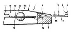
- FIG. 1shows a partial sectional view of an analysis system according to the invention
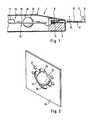
- FIG. 2shows a perspective view of a STHD appropriate for the invention
- FIG. 3shows a partial sectional view of the STHD according to FIG. 2;
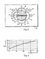
- FIG. 4shows a graphical representation of the temporal change of the measured value of a THS in the interior of a thermal mass for an embodiment according to FIGS. 2 and 3;
- FIG. 5shows a partial sectional view of an alternative design of a STHD
- FIG. 6shows a schematic representation of an alternative shape of a thermal mass.
- the analysis system shown in FIG. 1consists of an evaluation apparatus 2 and of single use (disposable) test elements 3 .
- the evaluation apparatus 2has a test element support 5 for fixing a test element 3 in the measuring position shown in FIG. 1 .
- the test element 3is fixed in the measuring position by appropriate means, as e.g. a leaf spring 6 .
- sample liquidis transported to a measurement zone 7 of the test element 3 .
- thisis accomplished by contacting a blood drop 8 to a sample application zone 9 , located at an end of the test element 3 , from which it is suctioned to the measurement zone 7 through a capillary gap 10 .
- a reagent layer 12which is dissolved by the sample liquid and reacts with its components, is located in the measurement zone 7 .
- the reactionleads to a measurable change in the measurement zone 7 .
- the measurement of an electrical quantityis performed by means of electrodes located in the measurement zone, not shown in the figure.
- a contactis made between the electrodes of the test element 3 and terminal contacts 14 of the test element support 5 .
- the terminal contacts 14are connected to a measuring and evaluation electronic device 15 , highly integrated for compact design and high reliability.
- the electronic deviceconsists mainly of a printed circuit board 16 and a special IC (ASIC) 17 . So far, the analysis system shown is conventional and does not require further explanation.
- a component of the electronic measuring and evaluation device 15is a temperature correction unit 18 comprising a temperature history imaging device STHD 20 , shown in more detail in FIGS. 2 and 3. It consists essentially of a spherical thermal mass 22 suspended in a heat insulated manner, a first temperature sensor (THS) 23 located in the center of the thermal mass 22 , and a second temperature sensor (RTS) 24 , located in the vicinity of the thermal mass 22 , but without contact to the thermal mass 22 .
- This RTSis, simultaneously, the ATS of the temperature correction unit.
- This STHDis an example of the above explained first type, in which the thermal conductivity of the thermal mass 22 is sufficiently high that it forms an isothermal heat storage element. Therefore, the first temperature sensor (THS) can be located at an almost randomly chosen point in the interior of the thermal mass 22 . With this design type, the outer shape of the thermal mass 22 is of minor significance for its function.
- the thermal mass 22is fixed in such a manner that its temperature essentially only depends from the temperature of the ambient air, and that an economic inexpensive production is possible.
- the thermal mass 22is in the embodiment shown integrated into a printed circuit board 16 ; preferably a common printed circuit board 16 is used for the measurement and evaluation electronic device as well as for the STHD.
- the printed circuit board 16has recesses 26 located in the vicinity of the thermal mass 26 , designed in a way that the thermal mass is touched and supported by only relatively thin fingers 27 . Thereby the heat transfer from the printed circuit board 16 to the thermal mass 22 is minimized.
- the first temperature sensor 23is located in a bore 29 of the thermal mass 22 , which after insertion of the temperature sensor is filled up with cast resin.
- the second temperature sensor 24is freely suspended at its wires in one of the recesses 26 . Both sensors 23 , 24 are connected via contact points 31 , to conductor tracks (not shown) of the printed circuit board 16 .
- the thermal mass 23was formed by an aluminum ball having a diameter of 6 mm and being fixed in a printed circuit board made of plastic of 0.8 mm thickness, as represented in the figure.
- Thermistors with a diameter of 0.25 mm and with conductor wires of a thickness of 0.025 mmwere used as temperature sensors.
- the thermal response of such a systemin case of a sudden temperature change from 18° C. to 22° C., is represented in FIG. 4 .
- the abscissashows the time in seconds and the ordinate shows the temperature in degree C. It becomes apparent that the temperature change occurring within three minutes is easily measurable.
- the comparison between the temperatures measured with the THS 23 and the RTS 24allows valid conclusions with respect to temperature changes in the past.
- the time constant of the temperature change of the STHDshould approximately correspond to the time constant of the delay of the temperature change of the ATS with respect to the temperature of the measurement zone.
- a single temperature sensor 24forms, on the one hand, the ATS of the temperature correction unit, and, on the other hand, the RTS of the STHD. This is cost-effective and, thus, favorable. In principle, it is, however, possible to supply an ATS in another location of the apparatus, independent from the STHD.
- FIG. 5shows an embodiment of the STHD which corresponds to the above mentioned second type, the thermal mass of the STHD of which has a very low thermal conductivity, and, at the same time, a sufficiently high heat capacity.
- the THS 23fixed in the interior of the thermal mass, is positioned in such a manner that the distance between the sensor and all points of the boundary surface of the thermal mass 32 , which are not isolated from the ambient air, is essentially the same.
- the thermal massis spherical and is in thermal contact with ambient air with almost its entire surface, this means that the THS should be located in the center of the thermal mass.
- a MBLS 24is arranged at the surface of the thermal mass 32 . Temperature variations in the ambient of such a STHD lead to the formation of spatial temperature gradients in the interior of the thermal mass 32 ; these are registered with two or more temperature sensors distributed in or at the thermal mass, enabling a very detailed tracing of the temperature history preceding the point of time at which the measurement is made, without consuming electric energy in the time before the measurement.
- FIG. 6shows a schematic sketch of a design in which the thermal mass is shaped as a disk; the flat sides of the disks are thermally insulated from the ambient air by insulating elements 34 , and the THS is located in the center of the disk.
Landscapes
- Health & Medical Sciences (AREA)
- Chemical & Material Sciences (AREA)
- Life Sciences & Earth Sciences (AREA)
- Hematology (AREA)
- Analytical Chemistry (AREA)
- General Physics & Mathematics (AREA)
- Electrochemistry (AREA)
- Physics & Mathematics (AREA)
- Molecular Biology (AREA)
- Biochemistry (AREA)
- General Health & Medical Sciences (AREA)
- Chemical Kinetics & Catalysis (AREA)
- Immunology (AREA)
- Pathology (AREA)
- Measuring And Recording Apparatus For Diagnosis (AREA)
- Investigating Or Analyzing Non-Biological Materials By The Use Of Chemical Means (AREA)
- Investigating Or Analysing Biological Materials (AREA)
- Investigating Or Analyzing Materials Using Thermal Means (AREA)
- Investigating, Analyzing Materials By Fluorescence Or Luminescence (AREA)
Abstract
Description
Claims (11)
Applications Claiming Priority (3)
| Application Number | Priority Date | Filing Date | Title |
|---|---|---|---|
| DE10032015ADE10032015A1 (en) | 2000-07-01 | 2000-07-01 | Test strip analysis unit for bodily fluid, employs temperature history correction system which will not drain batteries |
| DE10032015 | 2000-07-01 | ||
| DE10032015.5 | 2000-07-01 |
Publications (2)
| Publication Number | Publication Date |
|---|---|
| US20020037238A1 US20020037238A1 (en) | 2002-03-28 |
| US6787109B2true US6787109B2 (en) | 2004-09-07 |
Family
ID=7647427
Family Applications (1)
| Application Number | Title | Priority Date | Filing Date |
|---|---|---|---|
| US09/896,965Expired - LifetimeUS6787109B2 (en) | 2000-07-01 | 2001-06-29 | Test element analysis system |
Country Status (4)
| Country | Link |
|---|---|
| US (1) | US6787109B2 (en) |
| EP (1) | EP1176421A3 (en) |
| JP (1) | JP3400438B2 (en) |
| DE (1) | DE10032015A1 (en) |
Cited By (80)
| Publication number | Priority date | Publication date | Assignee | Title |
|---|---|---|---|---|
| US7025774B2 (en) | 2001-06-12 | 2006-04-11 | Pelikan Technologies, Inc. | Tissue penetration device |
| US7198606B2 (en) | 2002-04-19 | 2007-04-03 | Pelikan Technologies, Inc. | Method and apparatus for a multi-use body fluid sampling device with analyte sensing |
| US7229458B2 (en) | 2002-04-19 | 2007-06-12 | Pelikan Technologies, Inc. | Method and apparatus for penetrating tissue |
| US7232451B2 (en) | 2002-04-19 | 2007-06-19 | Pelikan Technologies, Inc. | Method and apparatus for penetrating tissue |
| US7244265B2 (en) | 2002-04-19 | 2007-07-17 | Pelikan Technologies, Inc. | Method and apparatus for penetrating tissue |
| US7258693B2 (en) | 2002-04-19 | 2007-08-21 | Pelikan Technologies, Inc. | Device and method for variable speed lancet |
| US7291117B2 (en) | 2002-04-19 | 2007-11-06 | Pelikan Technologies, Inc. | Method and apparatus for penetrating tissue |
| US7297151B2 (en) | 2002-04-19 | 2007-11-20 | Elikan Technologies, Inc. | Method and apparatus for body fluid sampling with improved sensing |
| US7297122B2 (en) | 2002-04-19 | 2007-11-20 | Pelikan Technologies, Inc. | Method and apparatus for penetrating tissue |
| US7316700B2 (en) | 2001-06-12 | 2008-01-08 | Pelikan Technologies, Inc. | Self optimizing lancing device with adaptation means to temporal variations in cutaneous properties |
| US7331931B2 (en) | 2002-04-19 | 2008-02-19 | Pelikan Technologies, Inc. | Method and apparatus for penetrating tissue |
| US7344894B2 (en) | 2001-10-16 | 2008-03-18 | Agilent Technologies, Inc. | Thermal regulation of fluidic samples within a diagnostic cartridge |
| US7344507B2 (en) | 2002-04-19 | 2008-03-18 | Pelikan Technologies, Inc. | Method and apparatus for lancet actuation |
| US7371247B2 (en) | 2002-04-19 | 2008-05-13 | Pelikan Technologies, Inc | Method and apparatus for penetrating tissue |
| US7374544B2 (en) | 2002-04-19 | 2008-05-20 | Pelikan Technologies, Inc. | Method and apparatus for penetrating tissue |
| US7410468B2 (en) | 2002-04-19 | 2008-08-12 | Pelikan Technologies, Inc. | Method and apparatus for penetrating tissue |
| US7481776B2 (en) | 2002-04-19 | 2009-01-27 | Pelikan Technologies, Inc. | Method and apparatus for penetrating tissue |
| US7485128B2 (en) | 2002-04-19 | 2009-02-03 | Pelikan Technologies, Inc. | Method and apparatus for penetrating tissue |
| US7491178B2 (en) | 2002-04-19 | 2009-02-17 | Pelikan Technologies, Inc. | Method and apparatus for penetrating tissue |
| US7524293B2 (en) | 2002-04-19 | 2009-04-28 | Pelikan Technologies, Inc. | Method and apparatus for penetrating tissue |
| US7537571B2 (en) | 2001-06-12 | 2009-05-26 | Pelikan Technologies, Inc. | Integrated blood sampling analysis system with multi-use sampling module |
| US7547287B2 (en) | 2002-04-19 | 2009-06-16 | Pelikan Technologies, Inc. | Method and apparatus for penetrating tissue |
| US7563232B2 (en) | 2002-04-19 | 2009-07-21 | Pelikan Technologies, Inc. | Method and apparatus for penetrating tissue |
| US7582063B2 (en) | 2000-11-21 | 2009-09-01 | Pelikan Technologies, Inc. | Blood testing apparatus having a rotatable cartridge with multiple lancing elements and testing means |
| US7582099B2 (en) | 2002-04-19 | 2009-09-01 | Pelikan Technologies, Inc | Method and apparatus for penetrating tissue |
| US7604592B2 (en) | 2003-06-13 | 2009-10-20 | Pelikan Technologies, Inc. | Method and apparatus for a point of care device |
| US7648468B2 (en) | 2002-04-19 | 2010-01-19 | Pelikon Technologies, Inc. | Method and apparatus for penetrating tissue |
| US7666149B2 (en) | 1997-12-04 | 2010-02-23 | Peliken Technologies, Inc. | Cassette of lancet cartridges for sampling blood |
| US7674232B2 (en) | 2002-04-19 | 2010-03-09 | Pelikan Technologies, Inc. | Method and apparatus for penetrating tissue |
| US7682318B2 (en) | 2001-06-12 | 2010-03-23 | Pelikan Technologies, Inc. | Blood sampling apparatus and method |
| US7699791B2 (en) | 2001-06-12 | 2010-04-20 | Pelikan Technologies, Inc. | Method and apparatus for improving success rate of blood yield from a fingerstick |
| US7717863B2 (en) | 2002-04-19 | 2010-05-18 | Pelikan Technologies, Inc. | Method and apparatus for penetrating tissue |
| US7749174B2 (en) | 2001-06-12 | 2010-07-06 | Pelikan Technologies, Inc. | Method and apparatus for lancet launching device intergrated onto a blood-sampling cartridge |
| US7780631B2 (en) | 1998-03-30 | 2010-08-24 | Pelikan Technologies, Inc. | Apparatus and method for penetration with shaft having a sensor for sensing penetration depth |
| US20100259394A1 (en)* | 2006-08-15 | 2010-10-14 | Bae Byeong-Woo | Mobile communication terminal equipped with temperature compensation function for use in bio-information measurement |
| US7822454B1 (en) | 2005-01-03 | 2010-10-26 | Pelikan Technologies, Inc. | Fluid sampling device with improved analyte detecting member configuration |
| US7850621B2 (en) | 2003-06-06 | 2010-12-14 | Pelikan Technologies, Inc. | Method and apparatus for body fluid sampling and analyte sensing |
| US7862520B2 (en) | 2002-04-19 | 2011-01-04 | Pelikan Technologies, Inc. | Body fluid sampling module with a continuous compression tissue interface surface |
| US7892185B2 (en) | 2002-04-19 | 2011-02-22 | Pelikan Technologies, Inc. | Method and apparatus for body fluid sampling and analyte sensing |
| US7892183B2 (en) | 2002-04-19 | 2011-02-22 | Pelikan Technologies, Inc. | Method and apparatus for body fluid sampling and analyte sensing |
| US7901362B2 (en) | 2002-04-19 | 2011-03-08 | Pelikan Technologies, Inc. | Method and apparatus for penetrating tissue |
| US7909778B2 (en) | 2002-04-19 | 2011-03-22 | Pelikan Technologies, Inc. | Method and apparatus for penetrating tissue |
| US7976476B2 (en) | 2002-04-19 | 2011-07-12 | Pelikan Technologies, Inc. | Device and method for variable speed lancet |
| US20110191059A1 (en)* | 2008-10-03 | 2011-08-04 | Bayer Healthcare Llc | Systems and Methods for Predicting Ambient Temperature in a Fluid Analyte Meter |
| US8197421B2 (en) | 2002-04-19 | 2012-06-12 | Pelikan Technologies, Inc. | Method and apparatus for penetrating tissue |
| US8221334B2 (en) | 2002-04-19 | 2012-07-17 | Sanofi-Aventis Deutschland Gmbh | Method and apparatus for penetrating tissue |
| US8262614B2 (en) | 2003-05-30 | 2012-09-11 | Pelikan Technologies, Inc. | Method and apparatus for fluid injection |
| US8267870B2 (en) | 2002-04-19 | 2012-09-18 | Sanofi-Aventis Deutschland Gmbh | Method and apparatus for body fluid sampling with hybrid actuation |
| US8282576B2 (en) | 2003-09-29 | 2012-10-09 | Sanofi-Aventis Deutschland Gmbh | Method and apparatus for an improved sample capture device |
| US8333710B2 (en) | 2002-04-19 | 2012-12-18 | Sanofi-Aventis Deutschland Gmbh | Tissue penetration device |
| US8360992B2 (en) | 2002-04-19 | 2013-01-29 | Sanofi-Aventis Deutschland Gmbh | Method and apparatus for penetrating tissue |
| US8401873B2 (en) | 2007-05-30 | 2013-03-19 | Bayer Healthcare Llc | Health data management device |
| US8556829B2 (en) | 2002-04-19 | 2013-10-15 | Sanofi-Aventis Deutschland Gmbh | Method and apparatus for penetrating tissue |
| US8574895B2 (en) | 2002-12-30 | 2013-11-05 | Sanofi-Aventis Deutschland Gmbh | Method and apparatus using optical techniques to measure analyte levels |
| US8641644B2 (en) | 2000-11-21 | 2014-02-04 | Sanofi-Aventis Deutschland Gmbh | Blood testing apparatus having a rotatable cartridge with multiple lancing elements and testing means |
| US8652831B2 (en) | 2004-12-30 | 2014-02-18 | Sanofi-Aventis Deutschland Gmbh | Method and apparatus for analyte measurement test time |
| US8668656B2 (en) | 2003-12-31 | 2014-03-11 | Sanofi-Aventis Deutschland Gmbh | Method and apparatus for improving fluidic flow and sample capture |
| US8702624B2 (en) | 2006-09-29 | 2014-04-22 | Sanofi-Aventis Deutschland Gmbh | Analyte measurement device with a single shot actuator |
| US8721671B2 (en) | 2001-06-12 | 2014-05-13 | Sanofi-Aventis Deutschland Gmbh | Electric lancet actuator |
| US8784335B2 (en) | 2002-04-19 | 2014-07-22 | Sanofi-Aventis Deutschland Gmbh | Body fluid sampling device with a capacitive sensor |
| US8828203B2 (en) | 2004-05-20 | 2014-09-09 | Sanofi-Aventis Deutschland Gmbh | Printable hydrogels for biosensors |
| WO2014140164A1 (en) | 2013-03-15 | 2014-09-18 | Roche Diagnostics Gmbh | Methods of using information from recovery pulses in electrochemical analyte measurements as well as devices, apparatuses and systems incorporating the same |
| WO2014140172A1 (en) | 2013-03-15 | 2014-09-18 | Roche Diagnostics Gmbh | Methods of failsafing electrochemical measurements of an analyte as well as devices, apparatuses and systems incorporating the same |
| WO2014140177A2 (en) | 2013-03-15 | 2014-09-18 | Roche Diagnostics Gmbh | Methods of detecting high antioxidant levels during electrochemical measurements and failsafing an analyte concentration therefrom as well as devices, apparatuses and systems incorporting the same |
| WO2014140170A1 (en) | 2013-03-15 | 2014-09-18 | Roche Diagnostics Gmbh | Methods of scaling data used to construct biosensor algorithms as well as devices, apparatuses and systems incorporating the same |
| US8965080B2 (en) | 2009-03-26 | 2015-02-24 | Koninklijke Philips N.V. | Perfusion imaging |
| US8965476B2 (en) | 2010-04-16 | 2015-02-24 | Sanofi-Aventis Deutschland Gmbh | Tissue penetration device |
| US9144401B2 (en) | 2003-06-11 | 2015-09-29 | Sanofi-Aventis Deutschland Gmbh | Low pain penetrating member |
| US9226699B2 (en) | 2002-04-19 | 2016-01-05 | Sanofi-Aventis Deutschland Gmbh | Body fluid sampling module with a continuous compression tissue interface surface |
| US9248267B2 (en) | 2002-04-19 | 2016-02-02 | Sanofi-Aventis Deustchland Gmbh | Tissue penetration device |
| US9314194B2 (en) | 2002-04-19 | 2016-04-19 | Sanofi-Aventis Deutschland Gmbh | Tissue penetration device |
| US9351680B2 (en) | 2003-10-14 | 2016-05-31 | Sanofi-Aventis Deutschland Gmbh | Method and apparatus for a variable user interface |
| US9375169B2 (en) | 2009-01-30 | 2016-06-28 | Sanofi-Aventis Deutschland Gmbh | Cam drive for managing disposable penetrating member actions with a single motor and motor and control system |
| US9386944B2 (en) | 2008-04-11 | 2016-07-12 | Sanofi-Aventis Deutschland Gmbh | Method and apparatus for analyte detecting device |
| US9427532B2 (en) | 2001-06-12 | 2016-08-30 | Sanofi-Aventis Deutschland Gmbh | Tissue penetration device |
| US9775553B2 (en) | 2004-06-03 | 2017-10-03 | Sanofi-Aventis Deutschland Gmbh | Method and apparatus for a fluid sampling device |
| US9795747B2 (en) | 2010-06-02 | 2017-10-24 | Sanofi-Aventis Deutschland Gmbh | Methods and apparatus for lancet actuation |
| US9820684B2 (en) | 2004-06-03 | 2017-11-21 | Sanofi-Aventis Deutschland Gmbh | Method and apparatus for a fluid sampling device |
| WO2018067235A1 (en) | 2016-10-05 | 2018-04-12 | Roche Diabetes Care, Inc. | Detection reagents and electrode arrangements for multi-analyte diagnostic test elements, as well as methods of using the same |
| US12345672B2 (en) | 2016-10-24 | 2025-07-01 | Roche Diabetes Care, Inc. | Methods of correcting for uncompensated resistances in the conductive elements of biosensors, as well as devices and systems incorporating the same |
Families Citing this family (13)
| Publication number | Priority date | Publication date | Assignee | Title |
|---|---|---|---|---|
| JP4505837B2 (en)* | 2002-01-18 | 2010-07-21 | アークレイ株式会社 | Analyzing device with temperature detector |
| DE10257322A1 (en)* | 2002-12-06 | 2004-06-24 | Endress + Hauser Flowtec Ag, Reinach | Process control meter for use in process control, e.g. for monitoring fluid mass flow rate, density, viscosity or pressure, has temperature compensation that takes into account historical temperature measurement behavior |
| US7040179B2 (en) | 2002-12-06 | 2006-05-09 | Endress+ Hauser Flowtec Ag | Process meter |
| JP4631565B2 (en)* | 2005-07-05 | 2011-02-16 | パナソニック株式会社 | Connecting device and measuring device using the same |
| EP2188628A2 (en) | 2007-09-13 | 2010-05-26 | Abbott Point Of Care, Inc. | Improved quality assurance system and method for point-of-care testing |
| US8344733B2 (en)* | 2008-03-27 | 2013-01-01 | Panasonic Corporation | Sample measurement device, sample measurement system and sample measurement method |
| CN102575963B (en)* | 2008-10-21 | 2014-07-16 | 生命扫描有限公司 | Multiple temperature measurements coupled with modeling |
| US20120116706A1 (en)* | 2009-06-30 | 2012-05-10 | Arkray, Inc. | Analysis Device and Analysis Method |
| US8801275B2 (en) | 2010-09-23 | 2014-08-12 | Bayer Healthcare Llc | System and apparatus for determining ambient temperatures for a fluid analyte system |
| CN102519618A (en)* | 2011-12-04 | 2012-06-27 | 东华大学 | High-precision temperature difference measuring method based on thermoelectric couple |
| CN102519599B (en)* | 2011-12-20 | 2014-03-12 | 苏州热工研究院有限公司 | Fuse automatic temperature measurement system |
| WO2015195487A1 (en)* | 2014-06-19 | 2015-12-23 | Bayer Healthcare Llc | Sensor clip for stacked sensor dispensing system, and system using the same |
| EP3217168A1 (en)* | 2016-03-08 | 2017-09-13 | Roche Diagnostics GmbH | Test element analysis system for the analytical examination of a sample |
Citations (6)
| Publication number | Priority date | Publication date | Assignee | Title |
|---|---|---|---|---|
| US4338174A (en) | 1979-01-08 | 1982-07-06 | Mcneilab, Inc. | Electrochemical sensor with temperature compensation means |
| US4720372A (en)* | 1983-06-16 | 1988-01-19 | Boehringer Mannheim Gmbh | Device for the evaluation of a flat test carrier for the analytical determination of components of body fluids |
| US5035862A (en) | 1987-12-17 | 1991-07-30 | Boehringer Mannheim Gmbh | Analytical system for the determination of a component of a fluid |
| US5405511A (en)* | 1993-06-08 | 1995-04-11 | Boehringer Mannheim Corporation | Biosensing meter with ambient temperature estimation method and system |
| US5972715A (en) | 1996-12-23 | 1999-10-26 | Bayer Corporation | Use of thermochromic liquid crystals in reflectometry based diagnostic methods |
| US6061128A (en)* | 1997-09-04 | 2000-05-09 | Avocet Medical, Inc. | Verification device for optical clinical assay systems |
Family Cites Families (17)
| Publication number | Priority date | Publication date | Assignee | Title |
|---|---|---|---|---|
| DE3340207A1 (en)* | 1983-11-07 | 1985-05-15 | WTW Wissenschaftlich-technische Werkstätten GmbH, 8120 Weilheim | Method for automatically detecting the temperature dependency of measuring signals |
| US4937863A (en)* | 1988-03-07 | 1990-06-26 | Digital Equipment Corporation | Software licensing management system |
| US4924378A (en)* | 1988-06-13 | 1990-05-08 | Prime Computer, Inc. | License mangagement system and license storage key |
| US5138712A (en)* | 1989-10-02 | 1992-08-11 | Sun Microsystems, Inc. | Apparatus and method for licensing software on a network of computers |
| EP0538464B1 (en)* | 1991-05-08 | 1998-12-30 | Digital Equipment Corporation | License management system |
| US5204897A (en)* | 1991-06-28 | 1993-04-20 | Digital Equipment Corporation | Management interface for license management system |
| US5438508A (en)* | 1991-06-28 | 1995-08-01 | Digital Equipment Corporation | License document interchange format for license management system |
| US5260999A (en)* | 1991-06-28 | 1993-11-09 | Digital Equipment Corporation | Filters in license management system |
| US5553143A (en)* | 1994-02-04 | 1996-09-03 | Novell, Inc. | Method and apparatus for electronic licensing |
| US5553139A (en)* | 1994-04-04 | 1996-09-03 | Novell, Inc. | Method and apparatus for electronic license distribution |
| US5790664A (en)* | 1996-02-26 | 1998-08-04 | Network Engineering Software, Inc. | Automated system for management of licensed software |
| US5905860A (en)* | 1996-03-15 | 1999-05-18 | Novell, Inc. | Fault tolerant electronic licensing system |
| US5758069A (en)* | 1996-03-15 | 1998-05-26 | Novell, Inc. | Electronic licensing system |
| US5754763A (en)* | 1996-10-01 | 1998-05-19 | International Business Machines Corporation | Software auditing mechanism for a distributed computer enterprise environment |
| US6029145A (en)* | 1997-01-06 | 2000-02-22 | Isogon Corporation | Software license verification process and apparatus |
| US6105069A (en)* | 1997-01-22 | 2000-08-15 | Novell, Inc. | Licensing controller using network directory services |
| DE19952215C2 (en)* | 1999-10-29 | 2001-10-31 | Roche Diagnostics Gmbh | Test element analysis system |
- 2000
- 2000-07-01DEDE10032015Apatent/DE10032015A1/ennot_activeWithdrawn
- 2001
- 2001-06-13EPEP01114307Apatent/EP1176421A3/ennot_activeWithdrawn
- 2001-06-26JPJP2001193264Apatent/JP3400438B2/ennot_activeExpired - Fee Related
- 2001-06-29USUS09/896,965patent/US6787109B2/ennot_activeExpired - Lifetime
Patent Citations (6)
| Publication number | Priority date | Publication date | Assignee | Title |
|---|---|---|---|---|
| US4338174A (en) | 1979-01-08 | 1982-07-06 | Mcneilab, Inc. | Electrochemical sensor with temperature compensation means |
| US4720372A (en)* | 1983-06-16 | 1988-01-19 | Boehringer Mannheim Gmbh | Device for the evaluation of a flat test carrier for the analytical determination of components of body fluids |
| US5035862A (en) | 1987-12-17 | 1991-07-30 | Boehringer Mannheim Gmbh | Analytical system for the determination of a component of a fluid |
| US5405511A (en)* | 1993-06-08 | 1995-04-11 | Boehringer Mannheim Corporation | Biosensing meter with ambient temperature estimation method and system |
| US5972715A (en) | 1996-12-23 | 1999-10-26 | Bayer Corporation | Use of thermochromic liquid crystals in reflectometry based diagnostic methods |
| US6061128A (en)* | 1997-09-04 | 2000-05-09 | Avocet Medical, Inc. | Verification device for optical clinical assay systems |
Cited By (176)
| Publication number | Priority date | Publication date | Assignee | Title |
|---|---|---|---|---|
| US7666149B2 (en) | 1997-12-04 | 2010-02-23 | Peliken Technologies, Inc. | Cassette of lancet cartridges for sampling blood |
| US7780631B2 (en) | 1998-03-30 | 2010-08-24 | Pelikan Technologies, Inc. | Apparatus and method for penetration with shaft having a sensor for sensing penetration depth |
| US8439872B2 (en) | 1998-03-30 | 2013-05-14 | Sanofi-Aventis Deutschland Gmbh | Apparatus and method for penetration with shaft having a sensor for sensing penetration depth |
| US8641644B2 (en) | 2000-11-21 | 2014-02-04 | Sanofi-Aventis Deutschland Gmbh | Blood testing apparatus having a rotatable cartridge with multiple lancing elements and testing means |
| US7582063B2 (en) | 2000-11-21 | 2009-09-01 | Pelikan Technologies, Inc. | Blood testing apparatus having a rotatable cartridge with multiple lancing elements and testing means |
| US7025774B2 (en) | 2001-06-12 | 2006-04-11 | Pelikan Technologies, Inc. | Tissue penetration device |
| US7537571B2 (en) | 2001-06-12 | 2009-05-26 | Pelikan Technologies, Inc. | Integrated blood sampling analysis system with multi-use sampling module |
| US8845550B2 (en) | 2001-06-12 | 2014-09-30 | Sanofi-Aventis Deutschland Gmbh | Tissue penetration device |
| US8721671B2 (en) | 2001-06-12 | 2014-05-13 | Sanofi-Aventis Deutschland Gmbh | Electric lancet actuator |
| US8679033B2 (en) | 2001-06-12 | 2014-03-25 | Sanofi-Aventis Deutschland Gmbh | Tissue penetration device |
| US7850622B2 (en) | 2001-06-12 | 2010-12-14 | Pelikan Technologies, Inc. | Tissue penetration device |
| US7316700B2 (en) | 2001-06-12 | 2008-01-08 | Pelikan Technologies, Inc. | Self optimizing lancing device with adaptation means to temporal variations in cutaneous properties |
| US8641643B2 (en) | 2001-06-12 | 2014-02-04 | Sanofi-Aventis Deutschland Gmbh | Sampling module device and method |
| US7041068B2 (en) | 2001-06-12 | 2006-05-09 | Pelikan Technologies, Inc. | Sampling module device and method |
| US8622930B2 (en) | 2001-06-12 | 2014-01-07 | Sanofi-Aventis Deutschland Gmbh | Tissue penetration device |
| US9694144B2 (en) | 2001-06-12 | 2017-07-04 | Sanofi-Aventis Deutschland Gmbh | Sampling module device and method |
| US8382683B2 (en) | 2001-06-12 | 2013-02-26 | Sanofi-Aventis Deutschland Gmbh | Tissue penetration device |
| US8360991B2 (en) | 2001-06-12 | 2013-01-29 | Sanofi-Aventis Deutschland Gmbh | Tissue penetration device |
| US8343075B2 (en) | 2001-06-12 | 2013-01-01 | Sanofi-Aventis Deutschland Gmbh | Tissue penetration device |
| US8337421B2 (en) | 2001-06-12 | 2012-12-25 | Sanofi-Aventis Deutschland Gmbh | Tissue penetration device |
| US7841992B2 (en) | 2001-06-12 | 2010-11-30 | Pelikan Technologies, Inc. | Tissue penetration device |
| US8282577B2 (en) | 2001-06-12 | 2012-10-09 | Sanofi-Aventis Deutschland Gmbh | Method and apparatus for lancet launching device integrated onto a blood-sampling cartridge |
| US9427532B2 (en) | 2001-06-12 | 2016-08-30 | Sanofi-Aventis Deutschland Gmbh | Tissue penetration device |
| US8216154B2 (en) | 2001-06-12 | 2012-07-10 | Sanofi-Aventis Deutschland Gmbh | Tissue penetration device |
| US8211037B2 (en) | 2001-06-12 | 2012-07-03 | Pelikan Technologies, Inc. | Tissue penetration device |
| US9802007B2 (en) | 2001-06-12 | 2017-10-31 | Sanofi-Aventis Deutschland Gmbh | Methods and apparatus for lancet actuation |
| US8206317B2 (en) | 2001-06-12 | 2012-06-26 | Sanofi-Aventis Deutschland Gmbh | Tissue penetration device |
| US8206319B2 (en) | 2001-06-12 | 2012-06-26 | Sanofi-Aventis Deutschland Gmbh | Tissue penetration device |
| US8162853B2 (en) | 2001-06-12 | 2012-04-24 | Pelikan Technologies, Inc. | Tissue penetration device |
| US9937298B2 (en) | 2001-06-12 | 2018-04-10 | Sanofi-Aventis Deutschland Gmbh | Tissue penetration device |
| US8123700B2 (en) | 2001-06-12 | 2012-02-28 | Pelikan Technologies, Inc. | Method and apparatus for lancet launching device integrated onto a blood-sampling cartridge |
| US7682318B2 (en) | 2001-06-12 | 2010-03-23 | Pelikan Technologies, Inc. | Blood sampling apparatus and method |
| US7699791B2 (en) | 2001-06-12 | 2010-04-20 | Pelikan Technologies, Inc. | Method and apparatus for improving success rate of blood yield from a fingerstick |
| US8016774B2 (en) | 2001-06-12 | 2011-09-13 | Pelikan Technologies, Inc. | Tissue penetration device |
| US7988645B2 (en) | 2001-06-12 | 2011-08-02 | Pelikan Technologies, Inc. | Self optimizing lancing device with adaptation means to temporal variations in cutaneous properties |
| US7981055B2 (en) | 2001-06-12 | 2011-07-19 | Pelikan Technologies, Inc. | Tissue penetration device |
| US7909775B2 (en) | 2001-06-12 | 2011-03-22 | Pelikan Technologies, Inc. | Method and apparatus for lancet launching device integrated onto a blood-sampling cartridge |
| US7749174B2 (en) | 2001-06-12 | 2010-07-06 | Pelikan Technologies, Inc. | Method and apparatus for lancet launching device intergrated onto a blood-sampling cartridge |
| US7344894B2 (en) | 2001-10-16 | 2008-03-18 | Agilent Technologies, Inc. | Thermal regulation of fluidic samples within a diagnostic cartridge |
| US9560993B2 (en) | 2001-11-21 | 2017-02-07 | Sanofi-Aventis Deutschland Gmbh | Blood testing apparatus having a rotatable cartridge with multiple lancing elements and testing means |
| US8337420B2 (en) | 2002-04-19 | 2012-12-25 | Sanofi-Aventis Deutschland Gmbh | Tissue penetration device |
| US8496601B2 (en) | 2002-04-19 | 2013-07-30 | Sanofi-Aventis Deutschland Gmbh | Methods and apparatus for lancet actuation |
| US7198606B2 (en) | 2002-04-19 | 2007-04-03 | Pelikan Technologies, Inc. | Method and apparatus for a multi-use body fluid sampling device with analyte sensing |
| US9907502B2 (en) | 2002-04-19 | 2018-03-06 | Sanofi-Aventis Deutschland Gmbh | Method and apparatus for penetrating tissue |
| US9839386B2 (en) | 2002-04-19 | 2017-12-12 | Sanofi-Aventis Deustschland Gmbh | Body fluid sampling device with capacitive sensor |
| US7862520B2 (en) | 2002-04-19 | 2011-01-04 | Pelikan Technologies, Inc. | Body fluid sampling module with a continuous compression tissue interface surface |
| US7875047B2 (en) | 2002-04-19 | 2011-01-25 | Pelikan Technologies, Inc. | Method and apparatus for a multi-use body fluid sampling device with sterility barrier release |
| US7874994B2 (en) | 2002-04-19 | 2011-01-25 | Pelikan Technologies, Inc. | Method and apparatus for penetrating tissue |
| US7892185B2 (en) | 2002-04-19 | 2011-02-22 | Pelikan Technologies, Inc. | Method and apparatus for body fluid sampling and analyte sensing |
| US7892183B2 (en) | 2002-04-19 | 2011-02-22 | Pelikan Technologies, Inc. | Method and apparatus for body fluid sampling and analyte sensing |
| US7901362B2 (en) | 2002-04-19 | 2011-03-08 | Pelikan Technologies, Inc. | Method and apparatus for penetrating tissue |
| US7901365B2 (en) | 2002-04-19 | 2011-03-08 | Pelikan Technologies, Inc. | Method and apparatus for penetrating tissue |
| US7909774B2 (en) | 2002-04-19 | 2011-03-22 | Pelikan Technologies, Inc. | Method and apparatus for penetrating tissue |
| US7731729B2 (en) | 2002-04-19 | 2010-06-08 | Pelikan Technologies, Inc. | Method and apparatus for penetrating tissue |
| US7909777B2 (en) | 2002-04-19 | 2011-03-22 | Pelikan Technologies, Inc | Method and apparatus for penetrating tissue |
| US7909778B2 (en) | 2002-04-19 | 2011-03-22 | Pelikan Technologies, Inc. | Method and apparatus for penetrating tissue |
| US7914465B2 (en) | 2002-04-19 | 2011-03-29 | Pelikan Technologies, Inc. | Method and apparatus for penetrating tissue |
| US7938787B2 (en) | 2002-04-19 | 2011-05-10 | Pelikan Technologies, Inc. | Method and apparatus for penetrating tissue |
| US7226461B2 (en) | 2002-04-19 | 2007-06-05 | Pelikan Technologies, Inc. | Method and apparatus for a multi-use body fluid sampling device with sterility barrier release |
| US7959582B2 (en) | 2002-04-19 | 2011-06-14 | Pelikan Technologies, Inc. | Method and apparatus for penetrating tissue |
| US7976476B2 (en) | 2002-04-19 | 2011-07-12 | Pelikan Technologies, Inc. | Device and method for variable speed lancet |
| US7717863B2 (en) | 2002-04-19 | 2010-05-18 | Pelikan Technologies, Inc. | Method and apparatus for penetrating tissue |
| US7981056B2 (en) | 2002-04-19 | 2011-07-19 | Pelikan Technologies, Inc. | Methods and apparatus for lancet actuation |
| US7713214B2 (en) | 2002-04-19 | 2010-05-11 | Pelikan Technologies, Inc. | Method and apparatus for a multi-use body fluid sampling device with optical analyte sensing |
| US7988644B2 (en) | 2002-04-19 | 2011-08-02 | Pelikan Technologies, Inc. | Method and apparatus for a multi-use body fluid sampling device with sterility barrier release |
| US9795334B2 (en) | 2002-04-19 | 2017-10-24 | Sanofi-Aventis Deutschland Gmbh | Method and apparatus for penetrating tissue |
| US8007446B2 (en) | 2002-04-19 | 2011-08-30 | Pelikan Technologies, Inc. | Method and apparatus for penetrating tissue |
| US7708701B2 (en) | 2002-04-19 | 2010-05-04 | Pelikan Technologies, Inc. | Method and apparatus for a multi-use body fluid sampling device |
| US8062231B2 (en) | 2002-04-19 | 2011-11-22 | Pelikan Technologies, Inc. | Method and apparatus for penetrating tissue |
| US8079960B2 (en) | 2002-04-19 | 2011-12-20 | Pelikan Technologies, Inc. | Methods and apparatus for lancet actuation |
| US7674232B2 (en) | 2002-04-19 | 2010-03-09 | Pelikan Technologies, Inc. | Method and apparatus for penetrating tissue |
| US8157748B2 (en) | 2002-04-19 | 2012-04-17 | Pelikan Technologies, Inc. | Methods and apparatus for lancet actuation |
| US7648468B2 (en) | 2002-04-19 | 2010-01-19 | Pelikon Technologies, Inc. | Method and apparatus for penetrating tissue |
| US8197423B2 (en) | 2002-04-19 | 2012-06-12 | Pelikan Technologies, Inc. | Method and apparatus for penetrating tissue |
| US8197421B2 (en) | 2002-04-19 | 2012-06-12 | Pelikan Technologies, Inc. | Method and apparatus for penetrating tissue |
| US8202231B2 (en) | 2002-04-19 | 2012-06-19 | Sanofi-Aventis Deutschland Gmbh | Method and apparatus for penetrating tissue |
| US9724021B2 (en) | 2002-04-19 | 2017-08-08 | Sanofi-Aventis Deutschland Gmbh | Method and apparatus for penetrating tissue |
| US7582099B2 (en) | 2002-04-19 | 2009-09-01 | Pelikan Technologies, Inc | Method and apparatus for penetrating tissue |
| US7563232B2 (en) | 2002-04-19 | 2009-07-21 | Pelikan Technologies, Inc. | Method and apparatus for penetrating tissue |
| US7547287B2 (en) | 2002-04-19 | 2009-06-16 | Pelikan Technologies, Inc. | Method and apparatus for penetrating tissue |
| US8221334B2 (en) | 2002-04-19 | 2012-07-17 | Sanofi-Aventis Deutschland Gmbh | Method and apparatus for penetrating tissue |
| US8235915B2 (en) | 2002-04-19 | 2012-08-07 | Sanofi-Aventis Deutschland Gmbh | Method and apparatus for penetrating tissue |
| US7229458B2 (en) | 2002-04-19 | 2007-06-12 | Pelikan Technologies, Inc. | Method and apparatus for penetrating tissue |
| US7232451B2 (en) | 2002-04-19 | 2007-06-19 | Pelikan Technologies, Inc. | Method and apparatus for penetrating tissue |
| US8267870B2 (en) | 2002-04-19 | 2012-09-18 | Sanofi-Aventis Deutschland Gmbh | Method and apparatus for body fluid sampling with hybrid actuation |
| US9498160B2 (en) | 2002-04-19 | 2016-11-22 | Sanofi-Aventis Deutschland Gmbh | Method for penetrating tissue |
| US7524293B2 (en) | 2002-04-19 | 2009-04-28 | Pelikan Technologies, Inc. | Method and apparatus for penetrating tissue |
| US7244265B2 (en) | 2002-04-19 | 2007-07-17 | Pelikan Technologies, Inc. | Method and apparatus for penetrating tissue |
| US8333710B2 (en) | 2002-04-19 | 2012-12-18 | Sanofi-Aventis Deutschland Gmbh | Tissue penetration device |
| US7491178B2 (en) | 2002-04-19 | 2009-02-17 | Pelikan Technologies, Inc. | Method and apparatus for penetrating tissue |
| US8337419B2 (en) | 2002-04-19 | 2012-12-25 | Sanofi-Aventis Deutschland Gmbh | Tissue penetration device |
| US7485128B2 (en) | 2002-04-19 | 2009-02-03 | Pelikan Technologies, Inc. | Method and apparatus for penetrating tissue |
| US7481776B2 (en) | 2002-04-19 | 2009-01-27 | Pelikan Technologies, Inc. | Method and apparatus for penetrating tissue |
| US7410468B2 (en) | 2002-04-19 | 2008-08-12 | Pelikan Technologies, Inc. | Method and apparatus for penetrating tissue |
| US8360992B2 (en) | 2002-04-19 | 2013-01-29 | Sanofi-Aventis Deutschland Gmbh | Method and apparatus for penetrating tissue |
| US8366637B2 (en) | 2002-04-19 | 2013-02-05 | Sanofi-Aventis Deutschland Gmbh | Method and apparatus for penetrating tissue |
| US8372016B2 (en) | 2002-04-19 | 2013-02-12 | Sanofi-Aventis Deutschland Gmbh | Method and apparatus for body fluid sampling and analyte sensing |
| US8382682B2 (en) | 2002-04-19 | 2013-02-26 | Sanofi-Aventis Deutschland Gmbh | Method and apparatus for penetrating tissue |
| US7374544B2 (en) | 2002-04-19 | 2008-05-20 | Pelikan Technologies, Inc. | Method and apparatus for penetrating tissue |
| US8388551B2 (en) | 2002-04-19 | 2013-03-05 | Sanofi-Aventis Deutschland Gmbh | Method and apparatus for multi-use body fluid sampling device with sterility barrier release |
| US9339612B2 (en) | 2002-04-19 | 2016-05-17 | Sanofi-Aventis Deutschland Gmbh | Tissue penetration device |
| US8403864B2 (en) | 2002-04-19 | 2013-03-26 | Sanofi-Aventis Deutschland Gmbh | Method and apparatus for penetrating tissue |
| US8414503B2 (en) | 2002-04-19 | 2013-04-09 | Sanofi-Aventis Deutschland Gmbh | Methods and apparatus for lancet actuation |
| US8430828B2 (en) | 2002-04-19 | 2013-04-30 | Sanofi-Aventis Deutschland Gmbh | Method and apparatus for a multi-use body fluid sampling device with sterility barrier release |
| US8435190B2 (en) | 2002-04-19 | 2013-05-07 | Sanofi-Aventis Deutschland Gmbh | Method and apparatus for penetrating tissue |
| US7371247B2 (en) | 2002-04-19 | 2008-05-13 | Pelikan Technologies, Inc | Method and apparatus for penetrating tissue |
| US8491500B2 (en) | 2002-04-19 | 2013-07-23 | Sanofi-Aventis Deutschland Gmbh | Methods and apparatus for lancet actuation |
| US7833171B2 (en) | 2002-04-19 | 2010-11-16 | Pelikan Technologies, Inc. | Method and apparatus for penetrating tissue |
| US8556829B2 (en) | 2002-04-19 | 2013-10-15 | Sanofi-Aventis Deutschland Gmbh | Method and apparatus for penetrating tissue |
| US8562545B2 (en) | 2002-04-19 | 2013-10-22 | Sanofi-Aventis Deutschland Gmbh | Tissue penetration device |
| US9314194B2 (en) | 2002-04-19 | 2016-04-19 | Sanofi-Aventis Deutschland Gmbh | Tissue penetration device |
| US8579831B2 (en) | 2002-04-19 | 2013-11-12 | Sanofi-Aventis Deutschland Gmbh | Method and apparatus for penetrating tissue |
| US7344507B2 (en) | 2002-04-19 | 2008-03-18 | Pelikan Technologies, Inc. | Method and apparatus for lancet actuation |
| US8636673B2 (en) | 2002-04-19 | 2014-01-28 | Sanofi-Aventis Deutschland Gmbh | Tissue penetration device |
| US7331931B2 (en) | 2002-04-19 | 2008-02-19 | Pelikan Technologies, Inc. | Method and apparatus for penetrating tissue |
| US7297122B2 (en) | 2002-04-19 | 2007-11-20 | Pelikan Technologies, Inc. | Method and apparatus for penetrating tissue |
| US9248267B2 (en) | 2002-04-19 | 2016-02-02 | Sanofi-Aventis Deustchland Gmbh | Tissue penetration device |
| US9226699B2 (en) | 2002-04-19 | 2016-01-05 | Sanofi-Aventis Deutschland Gmbh | Body fluid sampling module with a continuous compression tissue interface surface |
| US9186468B2 (en) | 2002-04-19 | 2015-11-17 | Sanofi-Aventis Deutschland Gmbh | Method and apparatus for penetrating tissue |
| US7297151B2 (en) | 2002-04-19 | 2007-11-20 | Elikan Technologies, Inc. | Method and apparatus for body fluid sampling with improved sensing |
| US8690796B2 (en) | 2002-04-19 | 2014-04-08 | Sanofi-Aventis Deutschland Gmbh | Method and apparatus for penetrating tissue |
| US9089294B2 (en) | 2002-04-19 | 2015-07-28 | Sanofi-Aventis Deutschland Gmbh | Analyte measurement device with a single shot actuator |
| US7291117B2 (en) | 2002-04-19 | 2007-11-06 | Pelikan Technologies, Inc. | Method and apparatus for penetrating tissue |
| US8784335B2 (en) | 2002-04-19 | 2014-07-22 | Sanofi-Aventis Deutschland Gmbh | Body fluid sampling device with a capacitive sensor |
| US8808201B2 (en) | 2002-04-19 | 2014-08-19 | Sanofi-Aventis Deutschland Gmbh | Methods and apparatus for penetrating tissue |
| US9089678B2 (en) | 2002-04-19 | 2015-07-28 | Sanofi-Aventis Deutschland Gmbh | Method and apparatus for penetrating tissue |
| US9072842B2 (en) | 2002-04-19 | 2015-07-07 | Sanofi-Aventis Deutschland Gmbh | Method and apparatus for penetrating tissue |
| US8905945B2 (en) | 2002-04-19 | 2014-12-09 | Dominique M. Freeman | Method and apparatus for penetrating tissue |
| US7258693B2 (en) | 2002-04-19 | 2007-08-21 | Pelikan Technologies, Inc. | Device and method for variable speed lancet |
| US8845549B2 (en) | 2002-04-19 | 2014-09-30 | Sanofi-Aventis Deutschland Gmbh | Method for penetrating tissue |
| US8574895B2 (en) | 2002-12-30 | 2013-11-05 | Sanofi-Aventis Deutschland Gmbh | Method and apparatus using optical techniques to measure analyte levels |
| US9034639B2 (en) | 2002-12-30 | 2015-05-19 | Sanofi-Aventis Deutschland Gmbh | Method and apparatus using optical techniques to measure analyte levels |
| US8262614B2 (en) | 2003-05-30 | 2012-09-11 | Pelikan Technologies, Inc. | Method and apparatus for fluid injection |
| US8251921B2 (en) | 2003-06-06 | 2012-08-28 | Sanofi-Aventis Deutschland Gmbh | Method and apparatus for body fluid sampling and analyte sensing |
| US7850621B2 (en) | 2003-06-06 | 2010-12-14 | Pelikan Technologies, Inc. | Method and apparatus for body fluid sampling and analyte sensing |
| US10034628B2 (en) | 2003-06-11 | 2018-07-31 | Sanofi-Aventis Deutschland Gmbh | Low pain penetrating member |
| US9144401B2 (en) | 2003-06-11 | 2015-09-29 | Sanofi-Aventis Deutschland Gmbh | Low pain penetrating member |
| US7604592B2 (en) | 2003-06-13 | 2009-10-20 | Pelikan Technologies, Inc. | Method and apparatus for a point of care device |
| US8945910B2 (en) | 2003-09-29 | 2015-02-03 | Sanofi-Aventis Deutschland Gmbh | Method and apparatus for an improved sample capture device |
| US8282576B2 (en) | 2003-09-29 | 2012-10-09 | Sanofi-Aventis Deutschland Gmbh | Method and apparatus for an improved sample capture device |
| US9351680B2 (en) | 2003-10-14 | 2016-05-31 | Sanofi-Aventis Deutschland Gmbh | Method and apparatus for a variable user interface |
| US9561000B2 (en) | 2003-12-31 | 2017-02-07 | Sanofi-Aventis Deutschland Gmbh | Method and apparatus for improving fluidic flow and sample capture |
| US8668656B2 (en) | 2003-12-31 | 2014-03-11 | Sanofi-Aventis Deutschland Gmbh | Method and apparatus for improving fluidic flow and sample capture |
| US8296918B2 (en) | 2003-12-31 | 2012-10-30 | Sanofi-Aventis Deutschland Gmbh | Method of manufacturing a fluid sampling device with improved analyte detecting member configuration |
| US9261476B2 (en) | 2004-05-20 | 2016-02-16 | Sanofi Sa | Printable hydrogel for biosensors |
| US8828203B2 (en) | 2004-05-20 | 2014-09-09 | Sanofi-Aventis Deutschland Gmbh | Printable hydrogels for biosensors |
| US9775553B2 (en) | 2004-06-03 | 2017-10-03 | Sanofi-Aventis Deutschland Gmbh | Method and apparatus for a fluid sampling device |
| US9820684B2 (en) | 2004-06-03 | 2017-11-21 | Sanofi-Aventis Deutschland Gmbh | Method and apparatus for a fluid sampling device |
| US8652831B2 (en) | 2004-12-30 | 2014-02-18 | Sanofi-Aventis Deutschland Gmbh | Method and apparatus for analyte measurement test time |
| US7822454B1 (en) | 2005-01-03 | 2010-10-26 | Pelikan Technologies, Inc. | Fluid sampling device with improved analyte detecting member configuration |
| US20100259394A1 (en)* | 2006-08-15 | 2010-10-14 | Bae Byeong-Woo | Mobile communication terminal equipped with temperature compensation function for use in bio-information measurement |
| US7947222B2 (en)* | 2006-08-15 | 2011-05-24 | Infopia Co., Ltd. | Mobile communication terminal equipped with temperature compensation function for use in bio-information measurement |
| US8702624B2 (en) | 2006-09-29 | 2014-04-22 | Sanofi-Aventis Deutschland Gmbh | Analyte measurement device with a single shot actuator |
| US8401873B2 (en) | 2007-05-30 | 2013-03-19 | Bayer Healthcare Llc | Health data management device |
| US9189598B2 (en) | 2007-05-30 | 2015-11-17 | Bayer Healthcare Llc | Fluid analyte meter |
| US10347371B2 (en) | 2007-05-30 | 2019-07-09 | Ascensia Diabetes Care Holdings Ag | Fluid analyte meter system |
| US9386944B2 (en) | 2008-04-11 | 2016-07-12 | Sanofi-Aventis Deutschland Gmbh | Method and apparatus for analyte detecting device |
| US8649997B2 (en) | 2008-10-03 | 2014-02-11 | Bayer Healthcare Llc | Systems and methods for predicting ambient temperature in a fluid analyte meter |
| US20110191059A1 (en)* | 2008-10-03 | 2011-08-04 | Bayer Healthcare Llc | Systems and Methods for Predicting Ambient Temperature in a Fluid Analyte Meter |
| US9375169B2 (en) | 2009-01-30 | 2016-06-28 | Sanofi-Aventis Deutschland Gmbh | Cam drive for managing disposable penetrating member actions with a single motor and motor and control system |
| US8965080B2 (en) | 2009-03-26 | 2015-02-24 | Koninklijke Philips N.V. | Perfusion imaging |
| US8965476B2 (en) | 2010-04-16 | 2015-02-24 | Sanofi-Aventis Deutschland Gmbh | Tissue penetration device |
| US9795747B2 (en) | 2010-06-02 | 2017-10-24 | Sanofi-Aventis Deutschland Gmbh | Methods and apparatus for lancet actuation |
| WO2014140170A1 (en) | 2013-03-15 | 2014-09-18 | Roche Diagnostics Gmbh | Methods of scaling data used to construct biosensor algorithms as well as devices, apparatuses and systems incorporating the same |
| WO2014140172A1 (en) | 2013-03-15 | 2014-09-18 | Roche Diagnostics Gmbh | Methods of failsafing electrochemical measurements of an analyte as well as devices, apparatuses and systems incorporating the same |
| WO2014140177A2 (en) | 2013-03-15 | 2014-09-18 | Roche Diagnostics Gmbh | Methods of detecting high antioxidant levels during electrochemical measurements and failsafing an analyte concentration therefrom as well as devices, apparatuses and systems incorporting the same |
| EP3385707A1 (en) | 2013-03-15 | 2018-10-10 | Roche Diabetes Care GmbH | Methods of scaling data used to construct biosensor algorithms as well as devices, apparatuses and systems incorporating the same |
| EP3385706A1 (en) | 2013-03-15 | 2018-10-10 | Roche Diabetes Care GmbH | Methods of scaling data used to construct biosensor algorithms as well as devices, apparatuses and systems incorporating the same |
| EP3388824A1 (en) | 2013-03-15 | 2018-10-17 | Roche Diabetes Care GmbH | Methods of detecting high antioxidant levels during electrochemical measurements and failsafing an analyte concentration therefrom as well as devices, apparatuses and systems incorporting the same |
| EP3388823A1 (en) | 2013-03-15 | 2018-10-17 | Roche Diabetes Care GmbH | Methods of scaling data used to construct biosensor algorithms as well as devices, apparatuses and systems incorporating the same |
| WO2014140164A1 (en) | 2013-03-15 | 2014-09-18 | Roche Diagnostics Gmbh | Methods of using information from recovery pulses in electrochemical analyte measurements as well as devices, apparatuses and systems incorporating the same |
| WO2018067235A1 (en) | 2016-10-05 | 2018-04-12 | Roche Diabetes Care, Inc. | Detection reagents and electrode arrangements for multi-analyte diagnostic test elements, as well as methods of using the same |
| US11230727B2 (en) | 2016-10-05 | 2022-01-25 | Roche Diabetes Care, Inc. | Detection reagents and electrode arrangements for multi-analyte diagnostic test elements, as well as methods of using the same |
| US12024735B2 (en) | 2016-10-05 | 2024-07-02 | Roche Diabetes Care, Inc. | Detection reagents and electrode arrangements for multi-analyte diagnostic test elements, as well as methods of using the same |
| EP4481375A2 (en) | 2016-10-05 | 2024-12-25 | F. Hoffmann-La Roche AG | Detection reagents and electrode arrangements for multi-analyte diagnostic test elements, as well as methods of using the same |
| US12345672B2 (en) | 2016-10-24 | 2025-07-01 | Roche Diabetes Care, Inc. | Methods of correcting for uncompensated resistances in the conductive elements of biosensors, as well as devices and systems incorporating the same |
Also Published As
| Publication number | Publication date |
|---|---|
| JP3400438B2 (en) | 2003-04-28 |
| DE10032015A1 (en) | 2002-01-10 |
| JP2002048786A (en) | 2002-02-15 |
| EP1176421A2 (en) | 2002-01-30 |
| EP1176421A3 (en) | 2004-03-03 |
| US20020037238A1 (en) | 2002-03-28 |
Similar Documents
| Publication | Publication Date | Title |
|---|---|---|
| US6787109B2 (en) | Test element analysis system | |
| US11015984B2 (en) | System and apparatus for determining ambient temperatures for a fluid analyte system | |
| US5232667A (en) | Temperature control for portable diagnostic system using a non-contact temperature probe | |
| US8313237B2 (en) | Multiple temperature measurements coupled with modeling | |
| JP2642517B2 (en) | Sensors for non-invasive in vivo determination of analyte and blood flow | |
| US9995593B2 (en) | Method for operating a sensor array | |
| JP5595029B2 (en) | Method for monitoring the thermal connectivity of a measuring cell | |
| US20040071182A1 (en) | Thermometry probe calibration method | |
| JP2004264297A (en) | Electronic thermometer | |
| JP4385021B2 (en) | Device for temperature control of the measuring cell in the analyzer, and measuring cell that can be inserted into the analyzer in a replaceable manner | |
| US20030035462A1 (en) | Method and apparatus for measuring the level of the contents | |
| RU192938U1 (en) | GAS SENSOR | |
| JPH06269275A (en) | Culture device and method of culture | |
| HK1160217B (en) | Analyte assessment system and method | |
| HK1160217A (en) | Analyte assessment system and method | |
| JPS61274233A (en) | Temperature detector | |
| HK1141583B (en) | Method for monitoring the thermal coupling of measuring cell |
Legal Events
| Date | Code | Title | Description |
|---|---|---|---|
| AS | Assignment | Owner name:ROCHE DIAGNOSTICS GMBH, GERMANY Free format text:ASSIGNMENT OF ASSIGNORS INTEREST;ASSIGNORS:HAAR, HANS-PETER;MEACHAM, GEORGE B.K.;REEL/FRAME:012462/0155;SIGNING DATES FROM 20010914 TO 20010917 | |
| AS | Assignment | Owner name:ROCHE DIAGNOSTICS CORPORATION, INDIANA Free format text:ASSIGNMENT OF ASSIGNORS INTEREST;ASSIGNOR:ROCHE DIAGNOSTICS GMBH;REEL/FRAME:012562/0537 Effective date:20010921 | |
| STCF | Information on status: patent grant | Free format text:PATENTED CASE | |
| AS | Assignment | Owner name:ROCHE DIAGNOSTICS OPERATIONS, INC., INDIANA Free format text:ASSIGNMENT OF ASSIGNORS INTEREST;ASSIGNOR:ROCHE DIAGNOSTICS CORPORATION;REEL/FRAME:015215/0061 Effective date:20040101 Owner name:ROCHE DIAGNOSTICS OPERATIONS, INC.,INDIANA Free format text:ASSIGNMENT OF ASSIGNORS INTEREST;ASSIGNOR:ROCHE DIAGNOSTICS CORPORATION;REEL/FRAME:015215/0061 Effective date:20040101 | |
| FPAY | Fee payment | Year of fee payment:4 | |
| FPAY | Fee payment | Year of fee payment:8 | |
| AS | Assignment | Owner name:ROCHE DIABETES CARE, INC., INDIANA Free format text:ASSIGNMENT OF ASSIGNORS INTEREST;ASSIGNOR:ROCHE DIAGNOSTICS OPERATIONS, INC.;REEL/FRAME:036008/0670 Effective date:20150302 | |
| FPAY | Fee payment | Year of fee payment:12 |