US6786879B1 - Gradient sequential compression system for preventing deep vein thrombosis - Google Patents
Gradient sequential compression system for preventing deep vein thrombosisDownload PDFInfo
- Publication number
- US6786879B1 US6786879B1US09/103,694US10369498AUS6786879B1US 6786879 B1US6786879 B1US 6786879B1US 10369498 AUS10369498 AUS 10369498AUS 6786879 B1US6786879 B1US 6786879B1
- Authority
- US
- United States
- Prior art keywords
- sleeve
- mode
- chambers
- indicator
- controller
- Prior art date
- Legal status (The legal status is an assumption and is not a legal conclusion. Google has not performed a legal analysis and makes no representation as to the accuracy of the status listed.)
- Expired - Fee Related
Links
Images


Classifications
- A—HUMAN NECESSITIES
- A61—MEDICAL OR VETERINARY SCIENCE; HYGIENE
- A61H—PHYSICAL THERAPY APPARATUS, e.g. DEVICES FOR LOCATING OR STIMULATING REFLEX POINTS IN THE BODY; ARTIFICIAL RESPIRATION; MASSAGE; BATHING DEVICES FOR SPECIAL THERAPEUTIC OR HYGIENIC PURPOSES OR SPECIFIC PARTS OF THE BODY
- A61H9/00—Pneumatic or hydraulic massage
- A61H9/005—Pneumatic massage
- A61H9/0078—Pneumatic massage with intermittent or alternately inflated bladders or cuffs
- A—HUMAN NECESSITIES
- A61—MEDICAL OR VETERINARY SCIENCE; HYGIENE
- A61H—PHYSICAL THERAPY APPARATUS, e.g. DEVICES FOR LOCATING OR STIMULATING REFLEX POINTS IN THE BODY; ARTIFICIAL RESPIRATION; MASSAGE; BATHING DEVICES FOR SPECIAL THERAPEUTIC OR HYGIENIC PURPOSES OR SPECIFIC PARTS OF THE BODY
- A61H2201/00—Characteristics of apparatus not provided for in the preceding codes
- A61H2201/50—Control means thereof
- A61H2201/5002—Means for controlling a set of similar massage devices acting in sequence at different locations on a patient
- A—HUMAN NECESSITIES
- A61—MEDICAL OR VETERINARY SCIENCE; HYGIENE
- A61H—PHYSICAL THERAPY APPARATUS, e.g. DEVICES FOR LOCATING OR STIMULATING REFLEX POINTS IN THE BODY; ARTIFICIAL RESPIRATION; MASSAGE; BATHING DEVICES FOR SPECIAL THERAPEUTIC OR HYGIENIC PURPOSES OR SPECIFIC PARTS OF THE BODY
- A61H2201/00—Characteristics of apparatus not provided for in the preceding codes
- A61H2201/50—Control means thereof
- A61H2201/5007—Control means thereof computer controlled
- A—HUMAN NECESSITIES
- A61—MEDICAL OR VETERINARY SCIENCE; HYGIENE
- A61H—PHYSICAL THERAPY APPARATUS, e.g. DEVICES FOR LOCATING OR STIMULATING REFLEX POINTS IN THE BODY; ARTIFICIAL RESPIRATION; MASSAGE; BATHING DEVICES FOR SPECIAL THERAPEUTIC OR HYGIENIC PURPOSES OR SPECIFIC PARTS OF THE BODY
- A61H2205/00—Devices for specific parts of the body
- A61H2205/10—Leg
- Y—GENERAL TAGGING OF NEW TECHNOLOGICAL DEVELOPMENTS; GENERAL TAGGING OF CROSS-SECTIONAL TECHNOLOGIES SPANNING OVER SEVERAL SECTIONS OF THE IPC; TECHNICAL SUBJECTS COVERED BY FORMER USPC CROSS-REFERENCE ART COLLECTIONS [XRACs] AND DIGESTS
- Y10—TECHNICAL SUBJECTS COVERED BY FORMER USPC
- Y10S—TECHNICAL SUBJECTS COVERED BY FORMER USPC CROSS-REFERENCE ART COLLECTIONS [XRACs] AND DIGESTS
- Y10S601/00—Surgery: kinesitherapy
- Y10S601/21—Kinesitherapy with computer control
Definitions
- the present inventionrelates to therapeutic medical devices and methods, and more particularly to devices and methods for improving venous blood flow in a patient.
- Deep vein thrombosis (DVT) and pulmonary embolism (PE)constitute major health problems in the United States. It has been estimated that 300,000 to 600,000 hospitalizations a year are attributable to DVT and PE conditions. Venous thromboembolism is also a significant risk in surgical patient populations where preoperative, operative and postoperative immobilization with concomitant loss of venous pump function causes blood stasis.
- prophylactic antithrombotic drugsfor preventing DVT are known to the art.
- efficacy of prophylactic administration of anticoagulants and antiplatelet agentshas been disputed, and is certainly not absolute.
- An alternative approach, attractive because of its freedom from hemorrhagic side effects,is the use of physical techniques such as elastic stockings, passive leg exercise, electrical calf stimulation and external pneumatic compression of the legs. Pneumatic compression has been the most studied and appears to be an effective therapeutic technique. For example, the results of a comparison trial between sequential compression and uniform compression are disclosed in article by E. W.
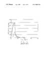
- FIG. 1illustrates an experimentally derived graph of an inflation cycle for a Model 5325 sequential compression device, manufactured by The Kendall Company. It is believed, however, that none of these sequential compression devices and methods provide for optimum blood flow velocity and volumetric flow rate in recumbent patients.
- DVDdeep vein thrombosis
- the compression systemincludes one or more sleeves (e.g., calf, thigh, calf and thigh, arm, forearm, torso, etc.) which can be wrapped around and releasably secured to a limb(s) of a user.
- the sleeveshave one or more inflatable chambers therein for retaining pressurized air upon inflation and for applying a compressive force to a limb.
- the compression systemalso includes a system controller for controlling transfers of pressurized air from an external or internal source to the inflatable chambers of the sleeves during respective inflation cycles, and for venting the pressurized air during respective deflation cycles. Transfers of air from the system controller to the sleeves are preferably provided by pneumatic connecting means which can include first and second conduit means.
- First and second conduit meanspreferably include a plurality of separate conduits or conduit ribbon.
- the system controllerincludes control means and first and second pluralities of feeder valves, responsive to control means, for enabling and disabling transfers of air from the source to respective ones of the inflatable chambers.
- Control meansis provided for controlling the sequence by which the feeder valves are directionally opened and closed so that during an inflation cycle a gradient of compressive forces can be sequentially established and maintained along a limb of a user for a predetermined time interval.
- control meansis provided for opening only one of the feeder valves to the source of pressurized air at a time, so that each of the inflatable chambers is independently inflated and regulated (e.g., measured and adjusted).
- Control meanspreferably includes a pressure transducer and means coupled thereto for sampling the pressures in each of the inflatable chambers and adjusting the pressures based on the samples so that the chambers are maintained at predetermined pressures, even if the limb sleeves are relatively loosely or tightly wrapped or the position of the limb is adjusted during treatment.
- the system controllerincludes first and second intermediate valves, connected between the source and the respective first and second pluralities of feeder valves.
- the intermediate valveswhich are responsive to control means as well, enable transfer of air from the source to the first and second pluralities of feeder valves during respective first and second inflation cycles and vent air from the first and second pluralities of feeder valves during respective deflation cycles.
- the feeder valves and intermediate valvesare directionally opened and closed to facilitate inflation, measurement and adjustment of the pressures in the limb sleeves.
- the system controlleralso preferably includes means for sensing whether pneumatic connecting means is attached thereto.
- Sensing meansmay include an infrared, Hall effect or reflective sensor(s), for example.
- Control meansalso includes means, responsive to the sensing means, for automatically adjusting from a default two-limb mode of operation to a one-limb mode by preventing the occurrence of either the first or second inflation cycles if the respective first or second conduit means is disconnected from the system controller.
- the first and second inflation cyclesare preferably 180° out of phase so that only one limb sleeve is being inflated at a time.
- the senoralso determines the selected mode of operation to be used by the controller.
- the current inventionutilizes different compression sleeves. These compression sleeves contain different numbers of inflation chambers and are formed differently to conform to and adequately compress selected portions of the body (i.e., calf, thigh, calf and thigh, arm, forearm, torso, ect.).
- the systemutilizes different pressure cycles for providing treatment to different body portions.
- the controller of the present inventiondetermines the proper mode of operation for the system by using a sensor. This sensor senses an indication from an indicator connected to the compression sleeve being used by the system. This indicator designates the mode of operation associated with the sleeve.
- the senorprovides a signal to the controller that identifies the selected mode of operation indicated by the sleeve.
- the controllerconfigures the system in accordance with this signal to operate in the selected mode of operation. This, in turn, allows for the automatic configuration of the controller for a selected treatment without the need for user input.
- the system controlleralso includes means for detecting low and high pressure fault conditions which can be caused by disconnected or occluded conduits, and sleeves that are wrapped too loosely or too tightly about a limb.
- compressive forcesare applied to a limb of a user by sequentially compressing a distal portion and then a relatively proximal portion of the limb to provide respective first and second radially inwardly directed compressive forces thereto.
- the first compressive forceis maintained above the second compressive force so that a decreasing pressure gradient is established in a proximal direction along the limb for a preselected time interval.
- the forceis preferably maintained by measuring the compressive forces and adjusting (i.e., increasing or decreasing) the compressive forces to maintain predetermined forces.
- the inventionincludes a method of applying compressive forces to a limb of a user using a multi-chambered inflatable limb sleeve surrounding the limb.
- the methodincludes the steps of pressurizing a first chamber of the limb sleeve to a first predetermined chamber pressure and then pressurizing a second chamber, disposed proximally relative to the first chamber, to a second preselected chamber pressure, after the first chamber reaches a first threshold pressure.
- the first threshold pressuremay be less than or equal to the first predetermined pressure.
- the second chamber pressurizing stepoccurs after a pressure in the first chamber has been established at the first predetermined pressure for at least a first time interval.
- a stepis also performed to regulate the pressures in the first and second chambers at their respective predetermined pressures so that a constant pressure gradient is established therebetween.
- the regulating stepmay include the steps of measuring a pressure in the first chamber while preventing depressurization of the second chamber and vice versa. Additionally, the regulating step may include the steps of measuring a pressure in the first chamber after it has been inflated to the first threshold pressure and then re-measuring a pressure in the first chamber, after the second chamber has been inflated to the second threshold pressure.
- the pressures in the chambersmay also be adjusted by performing periodic reinflating steps (and also deflating steps). Similar steps may also be performed to inflate third and fourth, etc. chambers of the limb sleeve, in sequence, so that a monotonically decreasing pressure gradient is established and maintained in a proximal direction between the chambers of a sleeve(s).
- a periodic adjusting stepmay also be performed to adjust the pressures in the chambers during an inflation cycle, by sampling (once or repeatedly) a pressure in a respective chamber to obtain a pressure sample and then adjusting the pressure by inflating or deflating the respective chamber, based on the value of the sample.
- Pressure samples from a respective chamber during an inflation cyclecan also be averaged to determine whether a critical overpressure condition occurred during a prior inflation cycle and/or occurred multiple consecutive times during prior inflation cycles. If a critical overpressure condition has occurred, subsequent inflation cycles can be disabled to maintain the respective sleeve(s) in a continuously deflated state until the system is reset or the critical condition is corrected.
- instantaneous pressure spikescan be compensated to prevent the occurrence of shutdown when a single or relatively few aberrant pressure samples have been measured.
- each of the feeder valves described with respect to the first embodimentare replaced by a pair of filling and monitoring valves.
- the filling valvesare preferably normally-closed valves and the monitoring valves are preferably normally-open valves.
- the filling valveshave an open state for enabling one-at-a-time transfer of pressured air from a source to the inflatable chambers of the first and second limb sleeves, in response to application of an energizing signal (e.g., logic 1), and a normally-closed blocking state which disconnects a respective chamber from the air source.
- the monitoring valveshave a normally-open state for enabling transfer of pressurized air from a respective inflatable chamber to an output thereof.
- These outputsare preferably pneumatically coupled through a corresponding three-way normally-open intermediate valve to a vent “V” or a pressure transducer in response to appropriate control signals.
- the monitoring valvesalso have a closed state (which can be achieved by application of an energizing signal (e.g., logic 1)) to prevent the escape of pressured air from a respective chamber when other chambers are being inflated or when the pressures in other chambers are being independently measured.
- an energizing signale.g., logic 1
- Control meanswhich is operatively connected to the filling, monitoring and intermediate valves, is provided for inflating a first inflatable chamber of the first limb sleeve by disposing the corresponding filling valve in an open state and the other filling valves in their respective normally-closed states.
- the corresponding first monitoring valveis also disposed in a normally-open state so that the pressure in the first inflatable chamber can be measured in real time as it is being inflated and thereafter when the first inflatable chamber is fully inflated and the corresponding filling valve has been closed.
- the pressure in a chambercan be continuously measured as the chamber is being inflated to its respective predetermined pressure. This provides real-time feedback of the chamber pressure.
- this real-time feedbackis used by the control means to adjust the inflation time of the respective chamber during the current or subsequent inflation cycle(s).
- the amount of time needed to measure the pressure in a chamber after the respective filling valve closescan also be reduced because the pneumatic connecting lines between the respective monitoring valve and the pressure transducer will already be at least partially pressurized at the respective chamber pressure when the measurement operation commences.
- FIG. 1is a graph illustrating an inflation cycle of a three chamber compression system, according to the prior art.
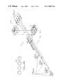
- FIG. 2is a perspective view of a system controller according to an embodiment of the present invention.
- FIG. 3Ais a graph illustrating first and second inflation cycles, according to the present invention.
- FIG. 3Bis a flow chart illustrating the operations performed by a system controller according to an embodiment of the present invention, during the first and second inflation cycles illustrated by FIG. 3 A.
- FIG. 4is a schematic diagram illustrating a compression system according to a first embodiment of the present invention.
- FIG. 5is a perspective view of a valve manifold and associated hardware connected thereto.
- FIG. 6Ais a perspective view of a preferred pneumatic connecting means utilized by the present invention.
- FIG. 6Bis a cross-sectional view of the pneumatic connecting means according to FIG. 6A, taken along the lines 6 B- 6 B′.
- FIG. 7is a schematic diagram illustrating a compression system according to a second embodiment of the present invention.
- FIG. 8is a perspective view of a universal connecting device according to one embodiment of the invention, wherein the device includes an optical signal generator.
- FIG. 9is a perspective view of a universal connecting device according to another embodiment of the invention.
- FIG. 10is a flow chart illustrating the operations performed by the universal connecting device according to an embodiment of the present invention.
- FIG. 11Ais perspective view of a universal connecting device including a Hall Effect sensor according to another embodiment of the invention.
- FIG. 11Bis an exploded perspective view of a connector for connecting to the universal connecting device according to another embodiment of the invention.
- the system controller 10includes a housing formed by top and bottom housing portions 13 and 11 , respectively.
- the top housing portion 13may include an on/off switch 12 and a sloped display 15 , such as an LED display or a more preferable liquid crystal display (LCD), for visually communicating chamber inflation information (e.g., pressure levels, chamber status), the mode of operation (e.g., one- or two-limb mode; and 2, 3 or 4-chamber mode, calf, thigh, calf and thigh, foot, arm, forearm, torso, ect.) and alarm, alert and fault conditions.
- chamber inflation informatione.g., pressure levels, chamber status
- the mode of operatione.g., one- or two-limb mode; and 2, 3 or 4-chamber mode, calf, thigh, calf and thigh, foot, arm, forearm, torso, ect.
- alarmalert and fault conditions.
- the displaymay also provide means, responsive to actuation by a user or health care professional, for preselecting the desired pressure levels to be achieved during a sleeve inflation cycle. Based on experiment, it was determined by the inventors herein that pressures ranging from 65-15 mmHg are most preferred.
- the system controller 10may also include an internal source of pressurized air 20 such as a compressor, however, an external pneumatic fitting or similar device (not shown) may be provided adjacent the controller housing for connecting the controller 10 to an external source of pressurized air.
- a bracket 19is also provided for securing an electrical cord (not shown) during periods of nonuse.
- the system controller 10also preferably includes a valve manifold 30 having a plurality of valves which facilitate inflation of limb sleeves 22 and 24 .
- the limb sleevesare preferably four-chamber sleeves.
- a plurality of single-chamber sleevesmay be provided as an equivalent substitute for a multi-chamber sleeve.
- the valves in the manifold 30are also directionally coupled and controlled to facilitate measurement and adjustment of pressures in the limb sleeves 22 , 24 , as explained more fully hereinbelow with respect to FIGS. 4 and 7.
- Preferred means 50 for pneumatically connecting the system controller 10 to the limb sleevesis also illustrated by FIGS. 6A-6B.
- Pneumatic connecting means 50preferably comprises first and second conduit means 54 , such as a plurality of flexible conduits or conduit ribbon 56 , as illustrated in FIG. 6 B.
- first and second conduit means 54such as a plurality of flexible conduits or conduit ribbon 56 , as illustrated in FIG. 6 B.
- a preferred method of applying compressive forces to a limb of a user using a multi-chambered inflatable limb sleeveincludes inflating (i.e., pressurizing) a first chamber of the limb sleeve to a first predetermined chamber pressure, shown as 50 mmHg, during a first inflation cycle (shown by solid lines).
- pressurization of a chambercauses a compression of the limb and provides a radially inwardly directed compressive force about the circumference of the limb.
- the predetermined chamber pressuresmay be user selected at the display, however respective default pressures are preferably fixed by the controller 10 .
- a second chamber of the sleevewhich is disposed proximally relative to the first chamber, is pressurized to a second predetermined pressure level, shown as 45 mmHg, by time C.
- Time Bpreferably occurs after the pressure in the first chamber reaches a threshold pressure, and more preferably after the first chamber pressure has been established at a respective predetermined pressure for a predetermined time interval.
- the threshold pressuremay be less than or equal the first predetermined pressure of 50 mmHg.
- the time interval between times B and Ais shown as 2.5 seconds, which is a default time interval.
- another predetermined time interval in the preferred range of 1-4 secondsmay also be selected by a health care professional to achieve a preferred venous blood flow rate, based on the particular therapeutic application and medical needs of the recumbent user.
- meansmay be provided at the display 15 for allowing preselection of the desired time interval.
- a measurementi.e., “sample” of the pressure in the first chamber is taken at least once. Based on this sample, the pressure in the first chamber is adjusted to the 50 mmHg level, if necessary. Adjustment of the pressure in a chamber can occur by either inflating the chamber if the pressure sample is too low or deflating the chamber if the pressure sample is too high. As illustrated, the pressure in the first chamber is adjusted from below 50 mmHg to above 50 mmHg at least once prior to time B.
- the third chamberis inflated to a third predetermined pressure level, shown as 40 mmHg. This occurs at time E.
- samples of the pressures in the first and second chambersare taken at least once and the pressures are independently adjusted to the 50 and 45 mmHg levels, if necessary.
- independent measurement of a pressure in a chamberoccurs without depressurizing the other chambers.
- independent adjustmentis achieved by pressurizing (or depressurizing) one chamber, while preventing pressurization (or depressurization) of the other chambers.
- the fourth chamberis inflated to a fourth predetermined pressure level, shown as 30 mmHg.
- a fourth predetermined pressure levelshown as 30 mmHg.
- the 50, 45, 40 and 30 mmHg levelsestablish a monotonically decreasing pressure gradient in a proximal direction along the limb of a user. It was determined by the inventors herein that a dual gradient of 5 mmHg between the first and second chambers and 10 mmHg between the third and fourth chambers is most preferred, however constant pressure levels in each chamber (i.e., no gradient) may also be possible if they are sequentially established.
- time Hpreferably occurs 2.5 seconds after the pressure in the fourth chamber reaches a respective threshold pressure, and more preferably after the fourth chamber pressure has been established at 30 mmHg. Accordingly, times B, D, F and H preferably occur 2.5 seconds after times A, C, E and G, respectively. Alternatively, these time intervals may be preselected to be of varying length.
- inflation of a first limb sleeveoccurs 180° (e.g., 30 seconds) out of phase with respect to inflation of a second limb sleeve.
- only one sleeveis preferably inflated at a time (although both could be simultaneously inflated).
- the inflation cycle for the second sleevebegins 30 seconds after initiation of the first inflation cycle.
- Both the first and second inflation cyclespreferably have default periods of 60 seconds, as illustrated. According to an aspect of the present invention, 30 seconds also sets the maximum inflation time.
- a sleevewill automatically be deflated if time H does not occur before 30 seconds have elapsed from the initiation of inflation.
- the second inflation cyclecould begin automatically at time H (i.e., after all chambers in the first sleeve have been inflated for the requisite 2.5 seconds), rather than at the 30 second mark.
- the inflation cycle period for each sleevewould typically vary from cycle to cycle, as would be understood by those skilled in the art.
- operations 70 performed by the system controller 10 during the first and second inflation cyclesare summarized.
- the operationsbegin with the first sleeve and then an operation is performed to inflate the most distal chamber in the sleeve that is uninflated, Block 72 .
- an operationis performed to determine whether a respective predetermined pressure in the chamber has been reached, Block 73 . If not, pressurization is continued. However, if the respective predetermined pressure for the chamber has been reached, an interval timer is started, Block 74 .
- the most distal chamber of the sleeveis preferably selected, Block 75 , and then measured to obtain a pressure sample, while preventing depressurization of the other chambers, Block 76 .
- an operationis then performed to adjust (+/ ⁇ ) the chamber pressure, Block 77 . This is repeated for each of the next proximal chambers which have already been inflated, Blocks 78 - 79 . Alternatively, this order of sampling the pressures (i.e., distal ⁇ proximal) may be reversed.
- the time intervale.g. 2.5 seconds
- Block 80the timer is reset (Block 81 ) and then a check is performed to see if all chambers have been inflated, Block 82 . If not, the next uninflated chamber is selected, Block 72 , and the operations are repeated.
- the time interval check performed at Block 80may be performed after each chamber has been checked instead of after all chambers have been checked. If the most proximal chamber has been inflated for the requisite elapsed time interval, then all chambers are deflated, Block 83 . This begins the deflation cycle for the respective sleeve. The next sleeve is then selected, Block 84 , and operations begin at Block 72 , so that inflation of the next sleeve preferably occurs 180° out of phase with the previous sleeve (i.e., 30 seconds after commencement of inflation for the previous sleeve).
- operationscan also be performed in parallel with those operations illustrated by Block 72 - 83 .
- a checkis performed to determine if a prior inflation cycle has occurred, Block 71 . If not, the normal operations (Blocks 72 - 82 ) are continued. If a prior inflation cycle has occurred, the pressure samples obtained from the prior cycle (or prior cycles) are averaged for each chamber, Block 84 . Based on these averages, a check is performed to determined whether an excessive pressure condition has occurred, Block 85 . If it has, subsequent inflation cycles are terminated until the system is reset, otherwise normal operations are continued. The system can be reset by accessing the display 15 .
- instantaneous spikes in the pressures of one or more chamberscan be compensated to prevent the occurrence of shutdown when a single or relatively few aberrant pressure samples have been measured during an inflation cycle or during consecutive inflation cycles (e.g., 5).
- these operationsare preferably performed by a system controller 10 having a preferred microprocessor-based control means 40 .
- Control means 40may also perform the function of detecting an occluded conduit and causing the display 15 to indicate a high pressure alert condition. For example, if a chamber inflating operation causes an excessive pressure (e.g., 100 mmHg) to be measured, control means 40 can automatically cause shutdown and alert the user.
- the compression systemcomprises a system controller 10 .
- the controller 10has means for controlling transfers of air from a source of pressurized air 20 (e.g., a compressor) to inflatable chambers of first and second limb sleeves 22 , 24 , respectively.
- a source of pressurized air 20e.g., a compressor
- each limb sleeve(or combinations of single- and dual-chamber sleeves) comprises a plurality of inflatable chambers 22 a-d and 24 a-d.
- dotted-lineshave been used to show pneumatic connections and solid-lines have been used to show electrical connections.
- the system controller 10further comprises first and second pluralities of feeder valves 26 , 28 for enabling and disabling transfers of air from the pressurized air source 20 to the inflatable chambers 22 a-d and 24 a-d.
- each of the first plurality of feeder valves 26 a-dis connected to respective ones of the chambers 22 a-d and each of the second plurality of feeder valves 28 a-d is connected to respective ones of the chambers 24 a-d.
- the feeder valves 26 a-d and 28 a-dare preferably Model 35 Series valves, which are publicly available from MAC Valves Inc. of Wixom, Michigan.
- Independent inflation control means 40is also provided for opening the feeder valves 26 a-d, 28 a-d one-at-a-time during a respective first or second inflation cycle.
- Control means 40is preferably microprocessor-based.
- an application specific integrated circuit (ASIC) or a multi-purpose microprocessor 42may be provided to perform command and control operations, based on instructions contained in memory 44 , such as programmable read-only memory (PROM).
- a multi-purpose microprocessorsuch as a Motorola Semiconductor Corp., Model MC68HC11A1 microprocessor may be used.
- Control means 40also preferably performs the function of regulating pressures in each of the inflatable chambers 22 a-d and 24 a-d.
- regulation meansis provided by the controller 10 for measuring the pressures in each of the chambers and for adjusting the pressures by intermittently inflating (and deflating) respective chambers to maintain pressure levels in the chambers at predetermined values, as illustrated by FIG. 3 A.
- Means for performing chamber pressure measurementspreferably comprises a pressure transducer 46 .
- the pressure transduceris preferably a Model MPX5050GP transducer, which is publicly available from Motorola Semiconductor Corp. of Phoenix, Ariz.
- the system controlleralso preferably comprises intermediate valve means, shown as three-way intermediate valves 25 and 27 .
- the intermediate valvesare preferably Model 170 Series valves, which are also publicly available from MAC Valves Inc.
- the intermediate valvesperform the function of enabling and disabling transfers of air from the source 20 to respective first and second pluralities of feeder valves 26 and 28 during the first and second inflation cycles.
- a pressure relief valve 34is also provided in case pressures within the controller 10 exceed a safe level.
- the controller of the present inventionis configurable to operate in several modes of operation.
- the controllermay be configured to treat deep vein thrombosis, as discussed in detail herein.
- the controllermay be configured to treat other ailments that respond positively to pneumatic compression, such as circulatory disorders, lymphatic disorders, organ failure, joint problems, soft tissue trauma, wound healing through management of localized congestion, counteracting shock by minimizing pooling of blood, physical massage, pneumatic tourniquets, etc.
- the modes of operation used for these treatmentsare based on several different factors. For instance, these different treatment plans may require a certain pattern for inflating the compression sleeves by the controller.
- the controller 40 of this embodimentwill control the feeder valves such that pressurized air is provided only to the connector connected to the compression sleeve and not to the other connector.
- the controller 40is configured to only supply pressurized air through the feeder valves that are connected to the compression sleeve such that the inflation chambers that are mounted on the calf or forearm section of the limb are provided with pressurized air.
- the controller of the present inventionalso includes other modes of operation.
- the compression system of the present inventionutilizes different types of compression sleeves that are configured to mount and conform to different body portions (i.e., calf, thigh, calf and thigh, foot, arm, forearm, torso, ect.). These differing compression sleeves require different compression cycles for proper treatment of the body portion to which they are mounted.
- the compression system of the present inventionalso uses many different treatment methods for the same body portion based on the particular medical problems of the patient (i.e., deep vein thrombosis, circulatory disorders, lymphatic disorders, organ failure, joint problems, soft tissue trauma, wound healing through management of localized congestion, counteracting shock by minimizing pooling of blood, physical massage, pneumatic tourniquet ect).
- These differing treatment methodsusually require different compression cycle patterns for inflating the compression sleeves.
- These differing compression cycles and the different treatment methodsconstitute different modes of operation for the controller.
- At least one mode of operationincludes an operation to verify and calibrate the system.
- a special compression sleeve or a calibration tube and connector, not shown, having only a single inflatable chamber or tube connected theretois used to verify/calibrate the pressure transducer 46 .
- the appropriate feeder valvesare opened by the controller to allow the pressure transducer 46 to be calibrated against a known pressure in the connected compression sleeve.
- the pressure of the transduceris displayed on the LCD display 15 and can be adjusted by the user to match the pressure in the sleeve or can be recalibrated by software in the microprocessor.
- the different modes of operation of the present inventionare typically stored in the controller memory 44 and are accessed by the microprocessor 42 to control the action of the feeder valves 26 a-d and 28 a-d.
- the modes of operationare defined by varying the number of chambers used, varying the amount of pressure in the sleeves, varying the pressurization times, and varying the sequence in which the compression sleeves are inflated.
- These modes of operation used by the microprocessor 42may be either selected manually from the memory by the user through the display 15 or automatically by the use of a sensor 36 .
- a sensor 36is used to select the proper mode of operation. For instance, in one embodiment, the sensor 36 is used to determine whether a compression sleeve 22 or 24 is connected to the controller 10 . The sensor 36 may also be used to determine whether more than one compression sleeve 22 or 24 is connected to the controller 40 for instances where two body portions (e.g., both legs) are to be treated.
- FIG. 8illustrates a connecting devices 17 a-b and connectors 58 a-b.
- This systemincludes optical signal generators 60 that direct an optical signal to the indicators 62 of the connectors to the compression sleeves 22 and 24 .
- the indicators 62will reflect the optical signals and these reflected optical signals will be sensed by sensors 36 .
- the controller 40receives the sensed signals from the sensors 36 and provides pressurized air to both of the compression sleeves 22 and 24 through the connecting devices 17 a and 17 b.
- the sensorwill send a signal to the microprocessor that designates that the sleeve 24 is not connected to the connecting device 17 b.
- the microprocessorwill then configure the controller to prevent the flow of pressurized air to that connecting device 17 b.
- the compression sleevesmay differ in many ways based on the part of the body they are configured to conform to or the particular treatment to be performed on the body portion.
- the compression sleeves 22 and 24may differ in the number of inflation chambers 22 a-d and 24 a-d.
- the indicator 62 connected to the selected compression sleeveindicates either the number of inflation chambers or the pressure cycle to be used for the desired treatment. This indication is sensed by the sensor 36 and provided to the controller 40 . The controller 40 then automatically adjusts to one, two, three, four, ect. inflation chambers or adjusts the cycle of pressure to the inflation chambers.
- the systemcan be configured automatically to perform several modes of operation without user input.
- the mode of configurationmay also be indicated by configuring the output ports of the feeder valves.
- a blocking devicemay be used to restrict the air flow from one or more of the output valves, where the blocked output ports designate a particular mode of operation (blocking two of the output ports to designate that only two chambers are to be inflated).
- the mode of operationis determined by the controller by initially assessing the pressure associated with each output port to determine whether the port is blocked. Based on this assessment of the output ports the controller determines the proper mode of operation.
- the output ports 17 a-b of FIG. 5are illustrated in greater detail.
- these output portsare configured to mate to a plurality of connectors 58 a-b that are associated with compression sleeves designated to operate with different modes of operation.
- These output portscontain output connectors 57 a-d that are connected to the feeder valves and are configured to mate to the connectors 58 a-b.
- a blocking device 59may be used to select the mode of operation of the controller.
- a blocking device 59may placed in front of one of the output ports (e.g., 57 b ). As such, the blocking device 59 restricts the flow of air through the port 57 b.
- the blocking device 59may be of any material sufficient to restrict the flow of air in the output port.
- the blocking devicecould be a plug disposed in the connectors 58 a-b and cover the output ports when the output connectors 17 a-b are connected to the connectors.
- the blocking devicemay be just a flat surface disposed in the connectors 58 a-b or even an adhesive tape covering the output port.
- the controllerinitially determines the pressure on each port 57 a-d. In particular, when the system is activated, the controller initially applies air flow through each of the feeder valves 26 a-d to the output ports 57 a-d. The blocking device 59 will restrict the flow of air through the output port 57 b. The controller monitors the pressure associated with each output port 57 a-d through the transducer. The transducer will sense a minimal pressure on the output ports 57 a, 57 c, 57 d because they are not blocked by the blocking device 59 .
- the transducerwill sense a relatively high pressure on the output port 57 b blocked by the blocking device 59 because the blocking device 59 has restricted the flow of air through the output port.
- the blocked output portrepresents a logic one because of the high pressure and the open output ports represent a logic 0 because of the minimal pressure.
- control deviceBased on the information from sensing the pressure of each output port, the control device will access memory and determine the mode of operation associated with the configuration of the blocked output port 57 b. The controller then configures the system to operate in the selected mode.
- the mode of operationmay also be designated in this embodiment by blocking two or more of the output ports 57 a-d or by blocking a selected combination of the output ports 57 a-d.
- the configuration of the system into the selected mode of operationis performed by use of a universal connecting device.
- FIG. 9illustrates one of the output ports 17 a of FIG. 5 in greater detail.
- these output portsare universal connecting devices configured to mate to a plurality of connectors that are associated with compression sleeves that are designated to operate with different modes of operation.
- the universal connecting devicecontains a connector housing 70 for mating with a connector 58 .
- a sensor 36is operably mounted to the connector housing 70 and an indicator 62 is connected to the connector.
- the indicator 62designates the selected mode of operation associated with the connector.
- FIG. 10illustrates the operation of the universal connecting device.
- a connector 58is mated to the connector housing 70 .
- An indicationis then provided from the indicator connected to the connector, which designates a selected mode of operation associated with the connector.
- This indicationis sensed by the sensor 36 .
- the sensor 36provides the sensed signal to the microprocessor 42 of the controller 40 .
- the controllerconfigures the system to operate in the predetermined mode of operation designated by the indicator based upon the definition of the respective mode provided by the indicator. (Block 140 ).
- the universal connecting deviceis illustrated herein in connection with a device for improving venous blood flow, this is for illustrative purposes only. It is contemplated that the universal connecting device can be used for any type of system. Therefore, the universal connecting device should not be limited to the embodiments shown.
- the universal connecting device of the present inventioncan be used to determine the selected mode of operation associated with a connecter connected thereto.
- the universal connecting devicecan have many different embodiments, three of which are shown below as examples.
- the sensor 36comprises a Hall Effect sensor for sensing an indication from the indicator.
- a Hall Effect sensordetects the presence of magnetic signals and provides a signal based on these sensed magnetic signals. For example, the north and south poles of a magnet generate differing magnetic fields.
- a Hall Effect sensorprovides different voltage signals based on whether it senses a positive magnetic signal (i.e., north pole of a magnet) or a negative magnetic signal (i.e., south pole of a magnet) or when no magnetic signal is present (i.e., no magnet at all). This aspect of the Hall Effect sensor can be utilized to detect different modes of operation associated with connectors connected to the universal connecting device. Hall Effect sensors are publicly available from Micro Switch, a division of Honeywell, Inc.
- FIG. 11Aillustrates an embodiment of the present invention including a Hall Effect sensor.
- the indicator 62is located in the connector 58 and comprises a plurality of magnets 64 .
- these magnetsare either configured in a particular arrangement or are placed in a designated position, wherein the arrangement or the position corresponds to a predetermined mode of operation associated with the connector.
- either the placement or the configuration (i.e., respective polarity) of the magnets in the connector or a combination of both placement and configurationcorresponds to a particular mode of operation for the system.
- the absence of a magnetmay also correspond to a particular mode.
- the placement and configuration of the magnetsalso correspond to a particular data point stored in the memory 42 of the controller, shown in FIG. 4 .
- the Hall Effect sensor 36senses the placement or configuration of the magnets and provides a signal to the controller 40 that represents the mode of operation associated with the connector.
- the microprocessor 42compares this sensed signal with the data stored in memory 44 and selects the data point that corresponds to the sensed signal. This data point is then used by the microprocessor 42 to configure the controller 40 for operating in the selected mode of operation.
- the controller 40will properly control the action of the feeder valves 26 a-d and 28 a-d to provide pressurized air to the inflatable chambers of the compression sleeve and will also control the feeder valves to provide the correct cycle of pressurized air to the inflatable chambers depending on the designated treatment.
- the Hall Effect sensor 36senses the configuration and placement of the magnets in the connector. For instance, in one embodiment a single magnet may be placed at different locations in the connector wherein each location signifies different modes of operation. In this embodiment, a Hall Effect sensor is placed at each possible location that the magnet may be placed. The Hall Effect sensor that corresponds to the placement of the magnet will provide a signal to the microprocessor. The microprocessor then compares the sensed signal to the data stored in memory 44 and configures the system to operate in the selected mode of operation.
- FIG. 11Billustrates another embodiment of the universal connector with a Hall Effect sensor.
- a plurality of magnets 64are configured such that their configuration designates a mode of operation associated with the connector 58 .
- the configuration of the magnetsrelates not only to their position in the connector 58 but also to their presence (i.e., is there a magnetic signal present) and polarity (i.e., north or south pole).
- the magnets 64are arranged by polarity in the connector.
- the polarity of these magnets 64are sensed by the Hall Effect sensors 36 , and these sensed signals are provided to the microprocessor 44 of the controller 40 which compares the sensed signals to the data in memory 42 .
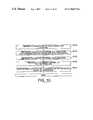
- Table 1shown below, illustrates the different combinations of two magnets used as indicators in a connector.
- two magnetscan used to designate nine different modes of operation based on the presence and or configuration of the poles of the magnets. These modes of operation can be stored in memory and retrieved based on the configuration of the magnets
- the universal connecting device of the present inventionfurther comprises an optical signal generator 60 and the indicator 62 connected to the connector 58 includes either a reflective or nonreflective material.
- the optical signal generator 60directs an optical signal toward the indicator 62 of the connector 58 and the indicator 62 will reflect the signal if a reflective material is used or will not reflect the signal if a nonreflective material is used. Whether the indicator 62 reflects or does not reflect the optical signal indicates different modes of operation for the system.
- the senor 36comprises an optical sensor that senses the optical signal reflected by the indicator 62 and provides a signal to the microprocessor 42 of the controller 40 designating whether a reflected signal was detected or not. Based on whether a signal was detected or not the microprocessor 42 determines the mode of operation associated with the connector 58 and configures the system.
- the indicator 62 of this embodimentmay comprise a plurality of reflective and nonreflective strips that can be configured to provide different combinations for designating particular modes of operation much like the magnets shown in Table 1.
- the indicator 62comprises a material having a specified level of reflectivity that corresponds to an associated mode of operation.
- the optical signal generator 60directs an optical signal to the indicator 62 attached to the connector.
- the indicator 62partially reflects the optical signal with a level of reflectivity that is associated with the selected mode of operation of the connector.
- This partially reflected signalis detected by the sensor 36 , and the sensor provides the detected signal to the microprocessor of the controller 60 .
- the microprocessor 42compares the detected signal to data in the memory 44 and based on this comparison configures the controller 40 to operate in the mode of operation designated by the indicator 62 .
- the system controller 10may include means, responsive to actuation from the display 15 , for manually configuring the controller 10 in the proper mode of operation.
- a controller 10 having a 2-sleeve/4-chamber default configuration, as illustrated and described herein,can be readily converted to a 3-chamber or 2-chamber system by selecting the desired mode at the display 15 .
- the controller 10may also include means, preferably responsive to actuation from the display, for configuring the controller 10 in a customized mode of operation which allows sleeves of different length to be used.
- a first sleeve having four chambersmay used on one limb and a second sleeve having two or three chambers may be used on another limb.
- the displaymay be used to select differing modes of operation for specific treatments. As will be understood by those skilled in the art, these customized modes of operation may be controlled by the microprocessor 42 . Selecting means, such as a membrane switch 16 , may be provided at the display 15 for selecting these modes of operation.
- the operationsbegin with the steps of connecting each of the chambers of the first and second limb sleeves 22 and 24 to respective conduits of first and second conduit ribbons 56 , and then inserting respective male connecting members 52 , at the source ends of the conduits, into each of the output ports 17 a and 17 b. Thereafter the controller is turned on by accessing the on/off switch 12 . This causes the controller 10 and particularly control means 40 to perform various diagnostic start-up operations, such as performing a check, which is responsive to sensing means 36 , to determine whether one or more of the sleeves is disconnected.
- Control means 40controls operations for inflating the first chamber 22 a to 50 mmHg by providing a first control signal (e.g., logic 0) to feeder valves 2 a and 28 a-d and to the second intermediate valve 27 .
- Second control signals(e.g., logic 1) are also provided to feeder valves 26 b-d, along the solid control lines, as shown.
- Second control signalsare also provided to the first intermediate valve 25 and to a source valve 32 , which is connected to the source of pressurized air 20 .
- These valvesare preferably three-way, normally-open, solenoid controlled valves, as illustrated.
- the application of a second or “energizing” control signal to the solenoid of each valvecauses the output of the valve to be directionally coupled to a first input, shown as opposite the input side of the valve.
- the application of a first or “deenergizing” signal to the solenoid of each valvecauses the output to be directionally coupled to a second input (or vent), shown as orthogonal to the output side of the valve.
- Chambers 22 b-d and chambers 24 a-dare disconnected from the source and are not inflated at this time.
- feeder valves 26 b-dwill be held in an energized but blocking state, as shown by the pneumatic termination (- - - -
- the feeder valves 26 a-d and 28 a-dhave been modified so that the first input is plugged.
- an energizing signalis also generated to open the source valve 32 and the first intermediate valve 25 .
- a deenergizing signalis also generated to open the feeder valve 2 a, which is now in a normally-open position and can accept pressurized air from the source 20 .
- control means 40also performs special startup control operations, which typically occur during the first 5-10 inflation cycles for a respective sleeve.
- the controllerinflates each chamber for a respective predetermined default time interval (retained in PROM 44 ) and then takes a measurement to determine whether the default time interval was long enough (or too long) to achieve the desired pressure level.
- control means 40will automatically increase the time interval so that during the next inflation cycle, the updated inflation time interval will be longer to correspond to the actual time needed for this chamber to inflate properly.
- These operationstypically occur repeatedly for each chamber during the first 5-10 inflation cycles or until the system “levels-out” at the desired inflation times. Because the respective inflation times are stored in volatile memory 48 , such as RAM, these operations will need to be repeated every time the system is turned-on or reset.
- the PROM 44may also contain a maximum fill time interval, so that if a chamber is not properly inflated in that interval, control means 40 will generate a fail-to-fill alert. This condition typically occurs when one of the conduits is disconnected from a chamber.
- These special control operationswill also need to be performed if the user-selected pressure levels, described above with reference to FIG. 2, are greater than or less than the default pressure levels of 50, 45, 40 and 30 mmHg. Moreover, if during the course of operation, the user or health care professional actuates the display 15 and adjusts the default pressure levels to new values, these special start-up control operations will be automatically performed again to generate new inflation times and adjust the system to the new pressure levels.
- chamber 22 awill inflate to the first predetermined pressure at time A, as shown.
- the deenergizing signalis applied to the source valve 32 to cause it to switch to its normally open position. When this occurs, the source will vent air through the controller housing to the surrounding atmosphere.
- the application of the deenergizing signal to the source valvealso closes off the system so that the pressure transducer can accurately sample the pressure in the first chamber 22 a.
- Control means 40also regulates the pressure in the first chamber 22 a by adjusting it to the first predetermined pressure if the sample is outside an acceptable pressure tolerance. For example, a short inflating or deflating step can be performed to adjust the pressure in the first chamber 22 a.
- the second or energizing control signalcan be temporarily removed from the first intermediate valve 25 in order to vent some of the air from the chamber through the feeder valve 26 A and first intermediate valve 25 .
- the energizing signalcan also be temporarily reapplied to the source valve to obtain another “burst” of air into the first chamber 22 A.
- an energizing signalis applied to feeder valve 2 a to cause it to enter a blocking state, as shown by the pneumatic termination (- - - -
- control means 40begins operations at time B for inflating the second chamber 22 b by applying an energizing signal to the source valve 32 and first intermediate valve 25 and applying a deenergizing signal to feeder valve 26 b, while holding feeder valves 2 a and 26 c-d in an energized (i.e., blocking) state.
- the second chamber 22 bwill be inflated to 45 mmHg and then control means 40 will deenergize the source valve 32 and energize feeder valve 26 b to thereby cause the source to vent to atmosphere while feeder valve 26 b blocks the escape of air from the second chamber 22 b.
- Measurement of the pressures in the first and second chambercan then be independently performed by first applying a temporary deenergizing signal to feeder valve 2 a to open it and then taking a pressure sample, followed by adjustment, if necessary. Next, a temporary deenergizing signal is applied to feeder valve 26 b, so that the pressure transducer 46 can sample the pressure in the second chamber 22 b as well.
- control means 40can again perform the necessary operations to separately adjust the pressures in the second chamber 22 b.
- the above-described operationsare again repeated at times D-G, so that at time H, control means 40 can provide a deenergizing signal to the first intermediate valve 25 and to each of the feeder valves 26 a-d so that all chambers vent through the first intermediate valve 25 .
- Analogous operationsare also performed by control means 40 to inflate and regulate the second sleeve 24 .
- deenergizing signalsare maintained at each of the feeder valves 26 a-d and first intermediate valve 25 so that the first sleeve 22 remains in a deflated state.
- control means 40provides energizing signals to open the source valve 32 and the second intermediate valve 27 and also provides energizing signals to feeder valves 28 b-d to maintain them in the blocking state. Accordingly, a connection is provided between the source 20 and first chamber 24 a at the beginning of the second inflation cycle.
- meanssuch as a membrane switch at the display 15 or an RS232 data port, may also be provided to allow adjustment of the controller so that a 2, 3, . . . , N-chamber mode of operation may be readily achieved in either sleeve.
- a controller 10 having a 2-sleeve/4-chamber default configuration as described hereincan be converted to a 3-chamber system by selecting this mode at the display 15 . Based on this selection, control means 40 would disable normal operations for inflating fourth chambers 22 d, 24 d by continuously providing energizing signals to feeder valves 26 d or 28 d to maintain them in a blocking state.
- control means 40would disable normal operations for inflating third and fourth chambers 24 c-d, by continuously providing energizing signals to feeder valves 28 c-d to continuously maintain them in a blocking state during the second inflation cycle.
- first and second output ports 17 a-b and associated conduits 17 c-dare provided for pneumatically connecting each of the outputs of the feeder valves 26 a-d and 28 a-d to respective ones of the conduits 54 .
- energizing and deenergizing control signals from control means 40 to feeder valves 26 a-d and 28 a-d and first and second intermediate valves 25 , 27are provided by electrical connections 29 , as shown.
- the compression systemcomprises a system controller 10 ′ for controlling transfers of pressurized air from an internal or external source 20 ′ to a plurality of inflatable chambers 22 a-d and 24 a-d during respective inflation cycles and for venting the source 20 ′ at vent “V” during respective deflation cycles and typically also when the pressure in any chamber is being measured after the respective chamber has been inflated to a predetermined level.
- a system controller 10 ′for controlling transfers of pressurized air from an internal or external source 20 ′ to a plurality of inflatable chambers 22 a-d and 24 a-d during respective inflation cycles and for venting the source 20 ′ at vent “V” during respective deflation cycles and typically also when the pressure in any chamber is being measured after the respective chamber has been inflated to a predetermined level.
- dotted-lineshave been used to show pneumatic connections and solid-lines have been used to show electrical connections.
- the system controller 10 ′further comprises first and second pluralities of feeder valve means 26 ′, 28 ′ for enabling and disabling transfers of air from the pressurized air source 20 ′ to the inflatable chambers 22 a-d and 24 a-d.
- Each of the four feeder valve means in the first and second pluralities 26 ′ and 28 ′preferably comprises a pair of filling and monitoring valves: (F 26 a, M 26 a ), (F 26 b, M 26 b ), (F 26 c, M 26 c ), (F 26 d, M 26 d ) and (F 28 a, M 28 a ), (F 28 b, M 28 b ), (F 28 c, M 28 c ), (F 28 d, M 28 d ).
- the use of a pair of filling and monitoring valvesprovides a number of preferred advantages relative to the normally-open feeder valves 26 a-d and 28 a-d of FIG. 4, as described more fully hereinbelow.
- the filling valves F 26 a-d and F 28 a-dare preferably normally closed valves and the monitoring valves M 26 a-d and M 28 a-d are preferably normally open valves. These valves, which may be combined as a valve manifold, are available from Matrix S.r.l, Ivrea, Italy.
- the filling valves F 26 a-d and F 28 a-dhave an open state for enabling one-at-a-time transfer of pressured air from the source 20 ′ to the inflatable chambers 22 a-d and 24 a-d of the first and second limb sleeves 22 and 24 , in response to application of an energizing signal (e.g., logic 1), and a normally-closed blocking state which disconnects a respective chamber from the air source 20 ′.
- the monitoring valves M 26 a-d and M 28 a-dhave a normally-open state for enabling transfer of pressurized air from a respective inflatable chamber (attached to an input thereof) to an output thereof.
- These outputscan be pneumatically coupled, through a corresponding three-way normally-open intermediate valve ( 29 or 31 ), to the vent “V” or a pressure transducer 46 in response to appropriate control signals.
- the intermediate valves 29 and 31have two outputs. In the first normally-open state, the input to each intermediate valve 29 and 31 is pneumatically connected to a first output thereof (which is connected to the vent “V”) and in the second open state the input to each intermediate valve is pneumatically connected to the pressure transducer 46 .
- Each intermediate valvecan be disposed in the second open state by applying an energizing signal thereto.
- the monitoring valves M 26 a-d and M 28 a-dalso have a closed state (which can be achieved by application of an energizing signal (e.g., logic 1)) to prevent the escape of pressured air from a respective chamber when other chambers are being inflated or when the pressures in other chambers are being independently measured.
- an energizing signale.g., logic 1
- Control means 40 ′which is operatively connected to the filling, monitoring and intermediate valves, is also provided for inflating a first inflatable chamber 22 a of the first limb sleeve 22 by disposing the corresponding filling valve (e.g., F 26 a ) in an open state and the other filling valves F 26 b-d and F 28 a-d in their respective normally-closed states.
- the corresponding filling valvee.g., F 26 a
- the corresponding first monitoring valve(e.g., M 26 a ) is also disposed in a normally-open state so that the pressure in the first inflatable chamber 22 a can be monitored (i.e., measured or sampled) in real time as it is being inflated and thereafter when the first inflatable chamber 22 a is fully inflated and the corresponding filling valve (e.g., F 26 a ) has been closed.
- Monitoring of the pressure in the first inflatable chamber 22 ais preferably achieved by also disposing the corresponding three-way intermediate valve (e.g., 29 ) in its second open state (in response to an energizing logic 1 signal) so that the pressure transducer 46 embodied in the control means 40 ′ becomes pneumatically coupled to the first inflatable chamber 22 a and performs a measurement of the pressure therein.
- the pressure in a chambercan be continuously measured as the chamber is being inflated to its respective predetermined pressure.
- Thisprovides real-time feedback of the chamber pressure.
- this real-time feedbackis used by the control means 40 ′ to adjust the inflation time of the respective chamber during the current or subsequent inflation cycle(s).
- the amount of time needed to measure the pressure in a chamber after the respective filling valve closescan also be reduced since the pneumatic connecting lines between the respective monitoring valve and the pressure transducer 46 will already be at least partially pressurized at the respective chamber pressure.
- the above described operations for inflating and measuring pressure in the first inflatable chamber 22 a of the first limb sleeve 22are repeatedly performed by the control means 40 ′ during the inflation of the remaining chambers of the limb sleeves 22 and 24 .
- the label “C”indicates that the respective valve is in a “closed” state
- the label “O”indicates that a respective valve is in an “open” state
- the label “V”indicates that a respective valve is in a “venting” state.
Landscapes
- Health & Medical Sciences (AREA)
- Epidemiology (AREA)
- Pain & Pain Management (AREA)
- Physical Education & Sports Medicine (AREA)
- Rehabilitation Therapy (AREA)
- Life Sciences & Earth Sciences (AREA)
- Animal Behavior & Ethology (AREA)
- General Health & Medical Sciences (AREA)
- Public Health (AREA)
- Veterinary Medicine (AREA)
- Massaging Devices (AREA)
Abstract
Description
| TABLE 1 |
| Configuration |
| Mode of | Magnet | 1 | Magnet 2 |
| 1 | No Magnet | No Magnet | |
| 2 | No Magnet | North | |
| 3 | No Magnet | South | |
| 4 | North | No Magnet | |
| 5 | South | No Magnet | |
| 6 | North | North | |
| 7 | North | South | |
| 8 | South | North | |
| 9 | South | South | |
| TABLE 2 | ||
| VALVE | ||
| F28 | M28 | ||||||||||||
| CHAMBER | F26a | M26a | F26b | M26b | F26c | F26d | M26d | 29 | 31 | a-d | |||
| FILL | |||||||||||||
| 22a | O | O | C | C | C | C | C | C | O | V | O | ||
| MONITOR | |||||||||||||
| 22a | C | O | C | C | C | C | C | C | O | V | O | ||
| FILL | |||||||||||||
| 22b | C | C | O | O | C | C | C | C | O | V | O | ||
| MONITOR | |||||||||||||
| 22b | C | C | C | O | C | C | C | C | O | V | O | ||
| FILL | |||||||||||||
| 22c | C | C | C | C | O | O | C | C | O | V | O | ||
| MONITOR | |||||||||||||
| 22c | C | C | C | C | C | O | C | C | O | V | O | ||
| FILL | |||||||||||||
| 22d | C | C | C | C | C | C | O | O | O | V | O | ||
| MONITOR | |||||||||||||
| 22d | C | C | C | C | C | C | C | O | O | V | C | O | |
| TABLE 3 | ||
| VALVE | ||
| F26 | M26 | ||||||||||||
| CHAMBER | F28a | M28a | F28b | M28b | F28c | F28d | M28d | 29 | 31 | a-d | |||
| FILL | |||||||||||||
| 24a | O | O | C | C | C | C | C | C | V | O | O | ||
| MONITOR | |||||||||||||
| 24a | C | O | C | C | C | C | C | C | V | O | O | ||
| FILL | |||||||||||||
| 24b | C | C | O | O | C | C | C | C | V | O | O | ||
| MONITOR | |||||||||||||
| 24b | C | C | C | O | C | C | C | C | V | O | O | ||
| FILL | |||||||||||||
| 24c | C | C | C | C | O | O | C | C | V | O | O | ||
| MONITOR | |||||||||||||
| 24c | C | C | C | C | C | O | C | C | V | O | O | ||
| FILL | |||||||||||||
| 24d | C | C | C | C | C | C | O | O | V | O | O | ||
| MONITOR | |||||||||||||
| 24d | C | C | C | C | C | C | C | O | V | O | C | O | |
Claims (17)
Priority Applications (3)
| Application Number | Priority Date | Filing Date | Title |
|---|---|---|---|
| US09/103,694US6786879B1 (en) | 1994-04-05 | 1998-06-24 | Gradient sequential compression system for preventing deep vein thrombosis |
| US09/755,313US6988423B2 (en) | 1994-04-05 | 2000-12-27 | Universal connecting device that designates an operational mode |
| US11/338,205US7252646B2 (en) | 1994-04-05 | 2006-01-24 | Universal connecting device that designates an operational mode |
Applications Claiming Priority (3)
| Application Number | Priority Date | Filing Date | Title |
|---|---|---|---|
| US08/223,429US5575762A (en) | 1994-04-05 | 1994-04-05 | Gradient sequential compression system and method for reducing the occurrence of deep vein thrombosis |
| US08/751,170US5951502A (en) | 1994-04-05 | 1996-11-15 | Gradient sequential compression system for preventing deep vein thrombosis |
| US09/103,694US6786879B1 (en) | 1994-04-05 | 1998-06-24 | Gradient sequential compression system for preventing deep vein thrombosis |
Related Parent Applications (1)
| Application Number | Title | Priority Date | Filing Date |
|---|---|---|---|
| US08/751,170Continuation-In-PartUS5951502A (en) | 1994-04-05 | 1996-11-15 | Gradient sequential compression system for preventing deep vein thrombosis |
Related Child Applications (1)
| Application Number | Title | Priority Date | Filing Date |
|---|---|---|---|
| US09/755,313DivisionUS6988423B2 (en) | 1994-04-05 | 2000-12-27 | Universal connecting device that designates an operational mode |
Publications (1)
| Publication Number | Publication Date |
|---|---|
| US6786879B1true US6786879B1 (en) | 2004-09-07 |
Family
ID=26917758
Family Applications (3)
| Application Number | Title | Priority Date | Filing Date |
|---|---|---|---|
| US09/103,694Expired - Fee RelatedUS6786879B1 (en) | 1994-04-05 | 1998-06-24 | Gradient sequential compression system for preventing deep vein thrombosis |
| US09/755,313Expired - Fee RelatedUS6988423B2 (en) | 1994-04-05 | 2000-12-27 | Universal connecting device that designates an operational mode |
| US11/338,205Expired - LifetimeUS7252646B2 (en) | 1994-04-05 | 2006-01-24 | Universal connecting device that designates an operational mode |
Family Applications After (2)
| Application Number | Title | Priority Date | Filing Date |
|---|---|---|---|
| US09/755,313Expired - Fee RelatedUS6988423B2 (en) | 1994-04-05 | 2000-12-27 | Universal connecting device that designates an operational mode |
| US11/338,205Expired - LifetimeUS7252646B2 (en) | 1994-04-05 | 2006-01-24 | Universal connecting device that designates an operational mode |
Country Status (1)
| Country | Link |
|---|---|
| US (3) | US6786879B1 (en) |
Cited By (59)
| Publication number | Priority date | Publication date | Assignee | Title |
|---|---|---|---|---|
| US20040054306A1 (en)* | 2002-01-11 | 2004-03-18 | Roth Rochelle B. | Inflatable massage garment |
| US20040068214A1 (en)* | 2002-10-03 | 2004-04-08 | Evans John James Henry | Control arrangements for therapeutic inflatable cell apparatus |
| US20050187500A1 (en)* | 2004-02-23 | 2005-08-25 | Perry Matthew J. | Compression treatment system |
| US20060058717A1 (en)* | 2004-09-14 | 2006-03-16 | Hui John C K | External counterpulsation device having a curvilinear bed |
| USD520963S1 (en) | 2004-02-23 | 2006-05-16 | Tyco Healthcare Group Lp | Controller |
| US20060167389A1 (en)* | 2002-10-03 | 2006-07-27 | Evans John J H | Control arrangements for therapeutic inflatable cell apparatus |
| US20070049853A1 (en)* | 2005-07-21 | 2007-03-01 | Bristol-Myers Squibb Company | Compression device for the limb |
| US20070088239A1 (en)* | 2000-06-02 | 2007-04-19 | Midtown Technology Ltd. | Inflatable massage garment |
| US20070112400A1 (en)* | 2003-09-24 | 2007-05-17 | Nathan Hamilton | Methods and apparatus for adjusting body core temperature |
| US20070161933A1 (en)* | 2005-10-27 | 2007-07-12 | Sundaram Ravikumar | Compression garment with heel elevation |
| US20070208304A1 (en)* | 2006-03-02 | 2007-09-06 | Sherwood Services Ag | Enteral feeding pump and feeding set therefor |
| US20070208305A1 (en)* | 2006-03-02 | 2007-09-06 | Sherwood Services Ag | Pump set with secure loading features |
| US20070208306A1 (en)* | 2006-03-02 | 2007-09-06 | Sherwood Services Ag | Pumping apparatus with secure loading features |
| US20070213650A1 (en)* | 2005-10-07 | 2007-09-13 | Thomas Raley | Apparatus for facilitating circulation |
| US20070249977A1 (en)* | 2006-01-24 | 2007-10-25 | Bristol-Myers Squibb Company | Pressurized medical device |
| US7314478B2 (en) | 2000-11-10 | 2008-01-01 | Vasomedical, Inc. | High efficiency external counterpulsation apparatus and method for controlling same |
| US20080058911A1 (en)* | 1998-06-08 | 2008-03-06 | Parish Overton L | Method and system for thermal and compression therapy relative to the prevention of deep vein thrombosis |
| US20080190346A1 (en)* | 2007-02-09 | 2008-08-14 | Drew Linden Krehbiel | Method and apparatus for variable floating structures |
| US20090145234A1 (en)* | 2007-12-07 | 2009-06-11 | Wright Linear Pump | Methods for enhancing pressure accuracy in a compression pump |
| US7560686B2 (en) | 2006-12-11 | 2009-07-14 | Tyco Healthcare Group Lp | Pump set and pump with electromagnetic radiation operated interlock |
| US7722562B2 (en) | 2006-03-02 | 2010-05-25 | Tyco Healthcare Group Lp | Pump set with safety interlock |
| US20100137764A1 (en)* | 2008-12-02 | 2010-06-03 | Patrick Eddy | Compression device and control system for applying pressure to a limb of a living being |
| US7763005B2 (en) | 2006-03-02 | 2010-07-27 | Covidien Ag | Method for using a pump set having secure loading features |
| US20100268130A1 (en)* | 2007-10-09 | 2010-10-21 | Khan Sitara R | Blood clot prevention device |
| US7846131B2 (en) | 2005-09-30 | 2010-12-07 | Covidien Ag | Administration feeding set and flow control apparatus with secure loading features |
| US20100331787A1 (en)* | 2009-06-30 | 2010-12-30 | Tyco Healthcare Group Lp | Female adaptor for feeding line |
| US20110008179A1 (en)* | 2007-07-02 | 2011-01-13 | Smith & Nephew Plc | Pressure control |
| US20110087142A1 (en)* | 2005-10-27 | 2011-04-14 | Sun Scientific, Inc. | Compression garments with heel elevation |
| US8021336B2 (en) | 2007-01-05 | 2011-09-20 | Tyco Healthcare Group Lp | Pump set for administering fluid with secure loading features and manufacture of component therefor |
| US20120016281A1 (en)* | 2007-05-31 | 2012-01-19 | Richards Sandy M | Pulmonary mattress |
| US8154274B2 (en) | 2010-05-11 | 2012-04-10 | Tyco Healthcare Group Lp | Safety interlock |
| US8182437B2 (en) | 2007-05-08 | 2012-05-22 | Wright Therapy Products, Inc. | Pneumatic compression therapy system and methods of using same |
| US8182521B2 (en) | 2003-09-24 | 2012-05-22 | Dynatherm Medical Inc. | Methods and apparatus for increasing blood circulation |
| US8317776B2 (en) | 2007-12-18 | 2012-11-27 | The Invention Science Fund I, Llc | Circulatory monitoring systems and methods |
| US20130014324A1 (en)* | 2011-07-12 | 2013-01-17 | Timothy Joseph Receveur | Health Care Delivery System and Components Thereof |
| US8409132B2 (en) | 2007-12-18 | 2013-04-02 | The Invention Science Fund I, Llc | Treatment indications informed by a priori implant information |
| US8603150B2 (en) | 2006-12-04 | 2013-12-10 | Carefusion 2200, Inc. | Methods and apparatus for adjusting blood circulation |
| US8636670B2 (en) | 2008-05-13 | 2014-01-28 | The Invention Science Fund I, Llc | Circulatory monitoring systems and methods |
| US8771329B2 (en) | 2010-01-08 | 2014-07-08 | Carefusion 2200, Inc. | Methods and apparatus for enhancing vascular access in an appendage to enhance therapeutic and interventional procedures |
| US8979915B2 (en) | 2010-04-19 | 2015-03-17 | Pulsar Scientific, LLC | Separable system for applying compression and thermal treatment |
| US9033906B2 (en) | 2010-08-12 | 2015-05-19 | Sun Scientific, Inc. | Therapeutic compression apparatus |
| US9295605B2 (en) | 2013-12-02 | 2016-03-29 | Wright Therapy Products, Inc. | Methods and systems for auto-calibration of a pneumatic compression device |
| US9308148B2 (en) | 2006-12-04 | 2016-04-12 | Thermatx, Inc. | Methods and apparatus for adjusting blood circulation |
| US9737238B2 (en) | 2012-08-18 | 2017-08-22 | Wright Therapy Products, Inc. | Methods for determining the size of body parts as part of compression therapy procedures |
| US9872812B2 (en) | 2012-09-28 | 2018-01-23 | Kpr U.S., Llc | Residual pressure control in a compression device |
| US9889063B2 (en) | 2012-06-11 | 2018-02-13 | Wright Therapy Products, Inc. | Methods and systems for determining use compliance of a compression therapy device |
| US20180125744A1 (en)* | 2016-11-08 | 2018-05-10 | Lear Corporation | Seat Assembly Having Massage Bladders with Reduced Pressure Sensor Count |
| US10195102B2 (en) | 2012-03-12 | 2019-02-05 | Tactile Systems Technology, Inc. | Compression therapy device with multiple simultaneously active chambers |
| US10292894B2 (en) | 2014-02-11 | 2019-05-21 | Tactile Systems Technology, Inc. | Compression therapy device and compression therapy protocols |
| US10328187B2 (en) | 2007-07-02 | 2019-06-25 | Smith & Nephew Plc | Systems and methods for controlling operation of negative pressure wound therapy apparatus |
| US10470967B2 (en) | 2014-01-20 | 2019-11-12 | Tactile Systems Technology, Inc. | Bespoke compression therapy device |
| US10507311B2 (en) | 2006-05-09 | 2019-12-17 | Thermotek, Inc. | Wound care method and system with one or both of vacuum-light therapy and thermally augmented oxygenation |
| US10507140B2 (en) | 2003-07-18 | 2019-12-17 | Thermotek, Inc. | Wound care method and system with one or both of vacuum-light therapy and thermally augmented oxygenation |
| US10617801B2 (en) | 2007-08-06 | 2020-04-14 | Smith & Nephew Plc | Canister status determination |
| US10765785B2 (en) | 2004-07-19 | 2020-09-08 | Thermotek, Inc. | Wound care and infusion method and system utilizing a therapeutic agent |
| US10772790B2 (en) | 2003-03-27 | 2020-09-15 | Tactile Systems Technology Inc. | Compression device for the limb |
| US10893998B2 (en) | 2018-10-10 | 2021-01-19 | Inova Labs Inc. | Compression apparatus and systems for circulatory disorders |
| US10918843B2 (en) | 2013-03-11 | 2021-02-16 | Thermotek, Inc. | Wound care and infusion method and system utilizing a thermally-treated therapeutic agent |
| US12121648B2 (en) | 2007-08-06 | 2024-10-22 | Smith & Nephew Plc | Canister status determination |
Families Citing this family (63)
| Publication number | Priority date | Publication date | Assignee | Title |
|---|---|---|---|---|
| US7846141B2 (en)* | 2002-09-03 | 2010-12-07 | Bluesky Medical Group Incorporated | Reduced pressure treatment system |
| GB0224986D0 (en)* | 2002-10-28 | 2002-12-04 | Smith & Nephew | Apparatus |
| GB0325129D0 (en) | 2003-10-28 | 2003-12-03 | Smith & Nephew | Apparatus in situ |
| GB0325126D0 (en) | 2003-10-28 | 2003-12-03 | Smith & Nephew | Apparatus with heat |
| US8100887B2 (en)* | 2004-03-09 | 2012-01-24 | Bluesky Medical Group Incorporated | Enclosure-based reduced pressure treatment system |
| US7909805B2 (en) | 2004-04-05 | 2011-03-22 | Bluesky Medical Group Incorporated | Flexible reduced pressure treatment appliance |
| US7708724B2 (en)* | 2004-04-05 | 2010-05-04 | Blue Sky Medical Group Incorporated | Reduced pressure wound cupping treatment system |
| US7776028B2 (en) | 2004-04-05 | 2010-08-17 | Bluesky Medical Group Incorporated | Adjustable overlay reduced pressure wound treatment system |
| US8062272B2 (en)* | 2004-05-21 | 2011-11-22 | Bluesky Medical Group Incorporated | Flexible reduced pressure treatment appliance |
| US10058642B2 (en)* | 2004-04-05 | 2018-08-28 | Bluesky Medical Group Incorporated | Reduced pressure treatment system |
| US7998125B2 (en)* | 2004-05-21 | 2011-08-16 | Bluesky Medical Group Incorporated | Hypobaric chamber treatment system |
| US7857777B2 (en)* | 2004-10-11 | 2010-12-28 | Convatec Technologies Inc. | Electro active compression bandage |
| GB0423410D0 (en)* | 2004-10-21 | 2004-11-24 | Bristol Myers Squibb Co | Compression device for the limb |
| US20080097263A1 (en)* | 2005-04-12 | 2008-04-24 | Grigoriev Anatoly I | Device for mechanical stimulation of the foot support areas |
| TWI376221B (en)* | 2005-06-08 | 2012-11-11 | Convatec Technologies Inc | Compression device for the foot |
| US20170181921A1 (en)* | 2005-09-23 | 2017-06-29 | New Tec Pty Ltd | Therapeutic Device |
| CN102895106A (en)* | 2005-09-23 | 2013-01-30 | 新技术私人有限公司 | An apparatus for preventing deep vein thrombosis |
| CN101404968B (en) | 2006-01-13 | 2012-04-18 | 康沃特克科技公司 | Devices, systems and methods for compression treatment of body parts |
| GB0601451D0 (en) | 2006-01-24 | 2006-03-08 | Bristol Myers Squibb Co | Control unit assembly |
| GB0601454D0 (en)* | 2006-01-24 | 2006-03-08 | Bristol Myers Squibb Co | A proximity detection apparatus |
| GB0622415D0 (en)* | 2006-11-10 | 2006-12-20 | Huntleigh Technology Plc | Compression system |
| US7931651B2 (en) | 2006-11-17 | 2011-04-26 | Wake Lake University Health Sciences | External fixation assembly and method of use |
| US8377016B2 (en) | 2007-01-10 | 2013-02-19 | Wake Forest University Health Sciences | Apparatus and method for wound treatment employing periodic sub-atmospheric pressure |
| US9642759B2 (en) | 2007-04-13 | 2017-05-09 | Stryker Corporation | Patient support with universal energy supply system |
| US20080262399A1 (en)* | 2007-04-20 | 2008-10-23 | Clotbuster Llc | Medical device |
| US8734370B1 (en)* | 2007-05-14 | 2014-05-27 | Mario Battiste Ignagni | Device for clearing mucus from the pulmonary system |
| GB0715263D0 (en)* | 2007-08-06 | 2007-09-12 | Smith & Nephew | Determining pressure |
| GB0712759D0 (en)* | 2007-07-02 | 2007-08-08 | Smith & Nephew | Measuring pressure |
| GB0715276D0 (en)* | 2007-08-06 | 2007-09-12 | Smith & Nephew | Pump control |
| KR101600041B1 (en) | 2007-10-10 | 2016-03-03 | 웨이크 포리스트 유니버시티 헬스 사이언시즈 | Devices and methods for treating spinal cord tissue |
| US9155541B2 (en)* | 2007-10-26 | 2015-10-13 | Global Monitors, Inc. | Compression vest for patients undergoing hemodialysis and in critical care |
| US9408773B2 (en) | 2007-10-26 | 2016-08-09 | Global Monitors, Inc. | Compression vest for patients undergoing hemodialysis and in critical care |
| US7879069B2 (en)* | 2007-10-26 | 2011-02-01 | Global Monitors, Inc. | Anti-pooling vest for patients undergoing hemodialysis and in critical care |
| RU2517588C2 (en) | 2008-01-09 | 2014-05-27 | Уэйк Форест Юниверсити Хелс Сайенсиз | Device and method for treating pathologies of central nervous system |
| US20090177184A1 (en)* | 2008-01-09 | 2009-07-09 | Christensen Scott A | Method and apparatus for improving venous access |
| ES2633142T3 (en) | 2008-07-18 | 2017-09-19 | Wake Forest University Health Sciences | Apparatus for modulation of cardiac tissue through topical application of vacuum to minimize death and cell damage |
| US8403870B2 (en) | 2009-09-15 | 2013-03-26 | Covidien Lp | Portable, self-contained compression device |
| US11000444B2 (en)* | 2010-02-08 | 2021-05-11 | Gnotrix, Llc | Treatment devices and methods |
| US9364651B2 (en) | 2010-02-23 | 2016-06-14 | Smiths Medical Asd, Inc. | Adapter with special fitting |
| US8506507B2 (en) | 2010-03-09 | 2013-08-13 | Covidien Lp | Venous augmentation system |
| US8845562B2 (en) | 2010-07-21 | 2014-09-30 | Hill-Rom Services, Inc. | Gas supply system |
| EP2486885B1 (en)* | 2011-02-09 | 2013-05-01 | Erbe Elektromedizin GmbH | Universal slide-on |
| US8870238B2 (en) | 2011-06-27 | 2014-10-28 | Smiths Medical Asd, Inc. | Fitting for medicament infusion systems |
| US9220833B2 (en) | 2011-06-27 | 2015-12-29 | Smiths Medical Asd, Inc. | Medicament infusion systems |
| US10737087B2 (en) | 2012-04-17 | 2020-08-11 | Smiths Medical Asd, Inc. | Filling fitting |
| CN102961240A (en)* | 2012-11-15 | 2013-03-13 | 绍兴福清卫生用品有限公司 | Air wave pressure therapeutic apparatus capable of judging auxiliary material and use method of air wave pressure therapeutic apparatus |
| CN104207927A (en)* | 2013-05-30 | 2014-12-17 | 杜清静 | Ischemia preadaptation training instrument |
| US20150216760A1 (en)* | 2014-02-04 | 2015-08-06 | Joseph Thomas Adams | Multi-Port Connection and Multi-Port Multiple Outlet Manifold |
| GB201419968D0 (en)* | 2014-11-10 | 2014-12-24 | Mjs Healthcare Ltd | Pressure cuff detection system |
| US10667984B2 (en) | 2015-12-18 | 2020-06-02 | Stryker Corporation | Systems and methods for operating patient therapy devices |
| US10076462B2 (en) | 2016-04-27 | 2018-09-18 | Radial Medical, Inc. | Adaptive compression therapy systems and methods |
| US10772673B2 (en) | 2016-05-02 | 2020-09-15 | Covidien Lp | Surgical energy system with universal connection features |
| US11410771B2 (en) | 2017-06-01 | 2022-08-09 | Stryker Corporation | Patient care devices with open communication |
| US11504927B2 (en)* | 2018-03-23 | 2022-11-22 | TurnCare, Inc. | Systems and methods for controlling and monitoring inflatable perfusion enhancement apparatus for mitigating contact pressure |
| US11980565B2 (en) | 2018-03-23 | 2024-05-14 | TurnCare, Inc. | Inflatable perfusion enhancement apparatuses and associated devices, systems and methods |
| JP7641899B2 (en)* | 2018-09-26 | 2025-03-07 | ターンケア,インコーポレイテッド | SYSTEM AND METHOD FOR CONTROLLING AND MONITORING AN INFLAPABLE PERFUSION AUGMENTATION DEVICE FOR CONTACT PRESSURE RELIEF - Patent application |
| US11559460B2 (en)* | 2019-02-28 | 2023-01-24 | Gary Chiu | Compression device |
| US12383455B2 (en)* | 2019-03-08 | 2025-08-12 | Medi Usa, L.P. | Pneumatic compression systems and compression treatment methods |
| US12329717B2 (en)* | 2019-03-29 | 2025-06-17 | Hill-Rom Services, Inc. | Control system for a patient therapy device |
| US11974964B2 (en) | 2019-03-29 | 2024-05-07 | Hill-Rom Services, Inc. | Patient support apparatus with integrated patient therapy device |
| US11931312B2 (en) | 2019-03-29 | 2024-03-19 | Hill-Rom Services, Inc. | User interface for a patient support apparatus with integrated patient therapy device |
| CN114177033A (en)* | 2021-12-30 | 2022-03-15 | 深圳市东吉联医疗科技有限公司 | Air wave physiotherapy instrument device |
| CN114366602A (en)* | 2022-01-25 | 2022-04-19 | 河南翔宇医疗设备股份有限公司 | An instrument for preventing deep vein thrombosis |
Citations (87)
| Publication number | Priority date | Publication date | Assignee | Title |
|---|---|---|---|---|
| US2361242A (en) | 1942-04-10 | 1944-10-24 | Blanche B Rosett | Therapeutic device and method of constructing same |
| US2533504A (en) | 1948-04-19 | 1950-12-12 | Philip Sampson J | Therapeutic apparatus |
| US2674231A (en) | 1952-01-02 | 1954-04-06 | Ohio Commw Eng Co | Power pack for massage suits |
| US2781041A (en) | 1955-12-02 | 1957-02-12 | Bernard D Weinberg | Progressive compression apparatus for treatment of bodily extremities |
| US3177866A (en) | 1962-04-24 | 1965-04-13 | R & W Medical Equipment Inc | Device for stimulating peripheral vascular circulation |
| US3288132A (en) | 1963-11-01 | 1966-11-29 | Anthony Myron L | Bladder structures useful in therapeutic treatment |
| US3391692A (en) | 1965-12-23 | 1968-07-09 | Theodore E. Spielberg | Variable-pressure casing and method of using for therapeutic purposes |
| US3442270A (en) | 1966-09-23 | 1969-05-06 | Charles Steinman | Surgical binder |
| US3467081A (en) | 1966-05-04 | 1969-09-16 | John P Glass | Inflatable massaging mattress |
| US3659593A (en) | 1970-04-20 | 1972-05-02 | Edwin G Vail | Cardiovascular assist device |
| US3701349A (en) | 1971-05-13 | 1972-10-31 | Leighton W Larson | Bi-valved cast |
| US3811431A (en) | 1973-01-17 | 1974-05-21 | M Apstein | Programmed venous assist pump |
| US3824992A (en) | 1973-03-16 | 1974-07-23 | Clinical Technology Inc | Pressure garment |
| US3856008A (en) | 1970-12-16 | 1974-12-24 | Jobst Institute | Elastic garment for imposing pressure on underlying body regions |
| US3862629A (en) | 1973-05-02 | 1975-01-28 | Nicholas R Rotta | Fluid pressure controlled means for producing peristaltic operation of series-connected inflatable chambers in therapeutic devices, pumps and the like |
| US3885554A (en) | 1972-12-08 | 1975-05-27 | Usm Corp | Apparatus for generating pulses of fluid pressure |
| JPS5076294A (en) | 1973-10-30 | 1975-06-21 | ||
| US3892229A (en) | 1973-12-06 | 1975-07-01 | Duane F Taylor | Apparatus for augmenting venous blood flow |
| US3901225A (en) | 1974-01-02 | 1975-08-26 | Jerry W Sconce | Inflatable splint |
| US3920006A (en) | 1974-01-02 | 1975-11-18 | Roy Lapidus Inc | Inflatable device for healing of tissue |
| US3924613A (en) | 1973-08-01 | 1975-12-09 | Armin Beck | Seat, particularly for motor vehicles |
| US3933150A (en) | 1974-02-08 | 1976-01-20 | David Clark Company Incorporated | Medical pneumatic trouser for emergency autotransfusion |
| US3942518A (en) | 1974-03-18 | 1976-03-09 | Jobst Institute, Inc. | Therapeutic intermittent compression apparatus |
| US4013069A (en) | 1975-10-28 | 1977-03-22 | The Kendall Company | Sequential intermittent compression device |
| US4029087A (en) | 1975-10-28 | 1977-06-14 | The Kendall Company | Extremity compression device |
| US4030488A (en) | 1975-10-28 | 1977-06-21 | The Kendall Company | Intermittent compression device |
| US4081150A (en) | 1977-01-05 | 1978-03-28 | Gordon Tyson | Multi-purpose therapeutic pad |
| US4091804A (en) | 1976-12-10 | 1978-05-30 | The Kendall Company | Compression sleeve |
| US4156425A (en) | 1977-08-10 | 1979-05-29 | The Kendall Company | Protective compression sleeve |
| US4198961A (en) | 1979-01-12 | 1980-04-22 | The Kendall Company | Compression device with sleeve retained conduits |
| US4202325A (en) | 1979-01-12 | 1980-05-13 | The Kendall Company | Compression device with improved fastening sleeve |
| US4207875A (en) | 1979-01-12 | 1980-06-17 | The Kendall Company | Compression device with knee accommodating sleeve |
| US4207876A (en) | 1979-01-12 | 1980-06-17 | The Kendall Company | Compression device with ventilated sleeve |
| US4253449A (en) | 1979-08-09 | 1981-03-03 | The Kendall Company | Compression device with connection system |
| US4280485A (en) | 1980-04-11 | 1981-07-28 | The Kendall Company | Compression device with simulator |
| US4295343A (en)* | 1979-07-20 | 1981-10-20 | Masahiko Izumi | Microbe-removing and air-conditioning apparatus |
| US4311135A (en) | 1979-10-29 | 1982-01-19 | Brueckner Gerald G | Apparatus to assist leg venous and skin circulation |
| US4320746A (en) | 1979-12-07 | 1982-03-23 | The Kendall Company | Compression device with improved pressure control |
| US4321929A (en) | 1979-10-12 | 1982-03-30 | Lemelson Jerome H | Tourniquet |
| US4324887A (en)* | 1978-08-16 | 1982-04-13 | President And Fellows Of Harvard College | Type II group B Streptococci polysaccharide |
| US4331133A (en) | 1980-06-30 | 1982-05-25 | The Kendall Company | Pressure measurement apparatus |
| US4335726A (en) | 1980-07-11 | 1982-06-22 | The Kendall Company | Therapeutic device with temperature and pressure control |
| US4338944A (en) | 1980-06-16 | 1982-07-13 | The Kendall Company | Therapeutic device |
| US4338923A (en) | 1977-10-13 | 1982-07-13 | Mego Afek Industrial Measuring Instruments | Inflatable-cell type body treating apparatus |
| US4370975A (en) | 1980-08-27 | 1983-02-01 | Wright Edward S | Apparatus promoting flow of a body fluid in a human limb |
| US4372297A (en) | 1980-11-28 | 1983-02-08 | The Kendall Company | Compression device |
| US4375217A (en) | 1980-06-04 | 1983-03-01 | The Kendall Company | Compression device with pressure determination |
| US4396010A (en) | 1980-06-30 | 1983-08-02 | The Kendall Company | Sequential compression device |
| US4402312A (en) | 1981-08-21 | 1983-09-06 | The Kendall Company | Compression device |
| US4408599A (en) | 1981-08-03 | 1983-10-11 | Jobst Institute, Inc. | Apparatus for pneumatically controlling a dynamic pressure wave device |
| US4413620A (en) | 1981-09-21 | 1983-11-08 | The Kendall Company | Abdominal restraint system |
| US4419988A (en) | 1981-08-03 | 1983-12-13 | Jobst Institute, Inc. | Electronic circuit for a dynamic pressure wave pneumatic control system |
| US4453538A (en) | 1977-04-07 | 1984-06-12 | Whitney John K | Medical apparatus |
| US4469099A (en) | 1980-10-02 | 1984-09-04 | Western Clinical Engineering Ltd. | Pneumatic torniquet |
| US4481937A (en) | 1980-06-30 | 1984-11-13 | The Kendall Company | Sequential compression device |
| US4574812A (en) | 1984-04-18 | 1986-03-11 | The Kendall Company | Arterial thrombus detection system and method |
| US4577626A (en) | 1981-02-09 | 1986-03-25 | Nikki Co., Ltd. | Massager |
| US4583522A (en) | 1983-09-01 | 1986-04-22 | Grumman Aerospace Corporation | Sequentially pressurized flight suit |
| US4597384A (en) | 1984-06-29 | 1986-07-01 | Gaymar Industries, Inc. | Sequential compression sleeve |
| US4702232A (en) | 1985-10-15 | 1987-10-27 | Electro-Biology, Inc. | Method and apparatus for inducing venous-return flow |
| US4762121A (en) | 1981-08-14 | 1988-08-09 | Mego Afek, Industrial Measuring Instruments | Massaging sleeve for body limbs |
| US4793328A (en) | 1988-02-19 | 1988-12-27 | The Kendall Company | Method of producing pressure for a multi-chambered sleeve |
| US4827912A (en) | 1987-09-18 | 1989-05-09 | The Kendall Company | Multi-chamber porting device |
| US4857196A (en)* | 1987-08-07 | 1989-08-15 | Asahi Kasei Kogyo Kabushiki Kaisha | Porous hollow fiber membrane and a method for the removal of a virus by using the same |
| US4858596A (en) | 1988-02-18 | 1989-08-22 | The Kendall Company | Portable sequential compression device |
| US4865020A (en) | 1987-06-29 | 1989-09-12 | Horace Bullard | Apparatus and method for movement of blood by external pressure |
| US4922893A (en) | 1987-06-22 | 1990-05-08 | Wright Linear Pump, Inc. | Method for promoting flow of a body fluid within a human limb |
| US4938208A (en) | 1989-03-16 | 1990-07-03 | The Kendall Company | Full length compressible sleeve |
| US4945905A (en) | 1988-02-08 | 1990-08-07 | The Kendall Company | Compressible boot |
| EP0392669A2 (en) | 1989-04-12 | 1990-10-17 | The Kendall Company | Device for applying compressive pressure against a patient's limb |
| US4971044A (en) | 1989-03-16 | 1990-11-20 | The Kendall Company | Method of manufacturing a compressible sleeve |
| USD315406S (en) | 1987-06-24 | 1991-03-12 | The Kendall Company | Sequential compression monitor for deep vein thrombosis |
| US5022387A (en) | 1987-09-08 | 1991-06-11 | The Kendall Company | Antiembolism stocking used in combination with an intermittent pneumatic compression device |
| US5031604A (en) | 1989-04-12 | 1991-07-16 | The Kendall Company | Device for applying compressive pressures to a patient's limb |
| US5117812A (en) | 1990-11-05 | 1992-06-02 | The Kendall Company | Segmented compression device for the limb |
| US5179941A (en) | 1988-06-07 | 1993-01-19 | Siems Otto Siemssen | Contractile sleeve element and compression sleeve made therefrom for the peristaltic treatment of extremities |
| US5186163A (en) | 1991-11-25 | 1993-02-16 | The Kendall Company | Compression device |
| US5263473A (en) | 1990-11-05 | 1993-11-23 | The Kendall Company | Compression device for the limb |
| US5307791A (en) | 1991-05-30 | 1994-05-03 | Matsushita Electric Works, Ltd. | Air massaging device with a precise pressure control |
| US5330720A (en)* | 1993-02-23 | 1994-07-19 | Hughes Aircraft Company | System for detecting fugitive emissions |
| US5343736A (en)* | 1992-06-15 | 1994-09-06 | Systems Chemistry, Inc. | Optical leak sensor and position detector |
| US5383894A (en) | 1993-07-30 | 1995-01-24 | The Kendall Co. | Compression device having stepper motor controlled valves |
| US5443440A (en) | 1993-06-11 | 1995-08-22 | Ndm Acquisition Corp. | Medical pumping apparatus |
| US5478119A (en) | 1993-09-16 | 1995-12-26 | The Kendall Company | Polarized manifold connection device |
| US5494801A (en)* | 1993-12-03 | 1996-02-27 | Biostar, Inc. | Microorganism antigen extraction methods |
| US5591200A (en) | 1994-06-17 | 1997-01-07 | World, Inc. | Method and apparatus for applying pressure to a body limb for treating edema |
| EP0781600A2 (en) | 1995-12-28 | 1997-07-02 | Ngk Insulators, Ltd. | Virus-removing filter |
Family Cites Families (4)
| Publication number | Priority date | Publication date | Assignee | Title |
|---|---|---|---|---|
| US4476706A (en)* | 1982-01-18 | 1984-10-16 | Delphian Partners | Remote calibration system |
| US4945899A (en)* | 1988-07-14 | 1990-08-07 | Nihon Kohden Corporation | Method of and apparatus for artificial respiration in synchronism with voluntary breathing of a patient |
| US5249121A (en)* | 1989-10-27 | 1993-09-28 | American Cyanamid Company | Remote control console for surgical control system |
| US5588954A (en)* | 1994-04-05 | 1996-12-31 | Beiersdorf-Jobst, Inc. | Connector for a gradient sequential compression system |
- 1998
- 1998-06-24USUS09/103,694patent/US6786879B1/ennot_activeExpired - Fee Related
- 2000
- 2000-12-27USUS09/755,313patent/US6988423B2/ennot_activeExpired - Fee Related
- 2006
- 2006-01-24USUS11/338,205patent/US7252646B2/ennot_activeExpired - Lifetime
Patent Citations (91)
| Publication number | Priority date | Publication date | Assignee | Title |
|---|---|---|---|---|
| US2361242A (en) | 1942-04-10 | 1944-10-24 | Blanche B Rosett | Therapeutic device and method of constructing same |
| US2533504A (en) | 1948-04-19 | 1950-12-12 | Philip Sampson J | Therapeutic apparatus |
| US2674231A (en) | 1952-01-02 | 1954-04-06 | Ohio Commw Eng Co | Power pack for massage suits |
| US2781041A (en) | 1955-12-02 | 1957-02-12 | Bernard D Weinberg | Progressive compression apparatus for treatment of bodily extremities |
| US3177866A (en) | 1962-04-24 | 1965-04-13 | R & W Medical Equipment Inc | Device for stimulating peripheral vascular circulation |
| US3288132A (en) | 1963-11-01 | 1966-11-29 | Anthony Myron L | Bladder structures useful in therapeutic treatment |
| US3391692A (en) | 1965-12-23 | 1968-07-09 | Theodore E. Spielberg | Variable-pressure casing and method of using for therapeutic purposes |
| US3467081A (en) | 1966-05-04 | 1969-09-16 | John P Glass | Inflatable massaging mattress |
| US3442270A (en) | 1966-09-23 | 1969-05-06 | Charles Steinman | Surgical binder |
| US3659593A (en) | 1970-04-20 | 1972-05-02 | Edwin G Vail | Cardiovascular assist device |
| US3856008A (en) | 1970-12-16 | 1974-12-24 | Jobst Institute | Elastic garment for imposing pressure on underlying body regions |
| US3701349A (en) | 1971-05-13 | 1972-10-31 | Leighton W Larson | Bi-valved cast |
| US3885554A (en) | 1972-12-08 | 1975-05-27 | Usm Corp | Apparatus for generating pulses of fluid pressure |
| US3811431A (en) | 1973-01-17 | 1974-05-21 | M Apstein | Programmed venous assist pump |
| US3824992A (en) | 1973-03-16 | 1974-07-23 | Clinical Technology Inc | Pressure garment |
| US3862629A (en) | 1973-05-02 | 1975-01-28 | Nicholas R Rotta | Fluid pressure controlled means for producing peristaltic operation of series-connected inflatable chambers in therapeutic devices, pumps and the like |
| US3924613A (en) | 1973-08-01 | 1975-12-09 | Armin Beck | Seat, particularly for motor vehicles |
| JPS5076294A (en) | 1973-10-30 | 1975-06-21 | ||
| US3892229A (en) | 1973-12-06 | 1975-07-01 | Duane F Taylor | Apparatus for augmenting venous blood flow |
| US3901225A (en) | 1974-01-02 | 1975-08-26 | Jerry W Sconce | Inflatable splint |
| US3920006A (en) | 1974-01-02 | 1975-11-18 | Roy Lapidus Inc | Inflatable device for healing of tissue |
| US3933150A (en) | 1974-02-08 | 1976-01-20 | David Clark Company Incorporated | Medical pneumatic trouser for emergency autotransfusion |
| US3942518A (en) | 1974-03-18 | 1976-03-09 | Jobst Institute, Inc. | Therapeutic intermittent compression apparatus |
| US4029087A (en) | 1975-10-28 | 1977-06-14 | The Kendall Company | Extremity compression device |
| US4013069A (en) | 1975-10-28 | 1977-03-22 | The Kendall Company | Sequential intermittent compression device |
| US4030488A (en) | 1975-10-28 | 1977-06-21 | The Kendall Company | Intermittent compression device |
| US4091804A (en) | 1976-12-10 | 1978-05-30 | The Kendall Company | Compression sleeve |
| US4081150A (en) | 1977-01-05 | 1978-03-28 | Gordon Tyson | Multi-purpose therapeutic pad |
| US4453538A (en) | 1977-04-07 | 1984-06-12 | Whitney John K | Medical apparatus |
| US4156425A (en) | 1977-08-10 | 1979-05-29 | The Kendall Company | Protective compression sleeve |
| US4338923A (en) | 1977-10-13 | 1982-07-13 | Mego Afek Industrial Measuring Instruments | Inflatable-cell type body treating apparatus |
| US4324887A (en)* | 1978-08-16 | 1982-04-13 | President And Fellows Of Harvard College | Type II group B Streptococci polysaccharide |
| US4202325A (en) | 1979-01-12 | 1980-05-13 | The Kendall Company | Compression device with improved fastening sleeve |
| US4207876A (en) | 1979-01-12 | 1980-06-17 | The Kendall Company | Compression device with ventilated sleeve |
| US4207875A (en) | 1979-01-12 | 1980-06-17 | The Kendall Company | Compression device with knee accommodating sleeve |
| US4198961A (en) | 1979-01-12 | 1980-04-22 | The Kendall Company | Compression device with sleeve retained conduits |
| US4295343A (en)* | 1979-07-20 | 1981-10-20 | Masahiko Izumi | Microbe-removing and air-conditioning apparatus |
| US4253449A (en) | 1979-08-09 | 1981-03-03 | The Kendall Company | Compression device with connection system |
| US4321929A (en) | 1979-10-12 | 1982-03-30 | Lemelson Jerome H | Tourniquet |
| US4311135A (en) | 1979-10-29 | 1982-01-19 | Brueckner Gerald G | Apparatus to assist leg venous and skin circulation |
| US4320746A (en) | 1979-12-07 | 1982-03-23 | The Kendall Company | Compression device with improved pressure control |
| US4280485A (en) | 1980-04-11 | 1981-07-28 | The Kendall Company | Compression device with simulator |
| US4375217A (en) | 1980-06-04 | 1983-03-01 | The Kendall Company | Compression device with pressure determination |
| US4338944A (en) | 1980-06-16 | 1982-07-13 | The Kendall Company | Therapeutic device |
| US4331133A (en) | 1980-06-30 | 1982-05-25 | The Kendall Company | Pressure measurement apparatus |
| US4481937A (en) | 1980-06-30 | 1984-11-13 | The Kendall Company | Sequential compression device |
| US4396010A (en) | 1980-06-30 | 1983-08-02 | The Kendall Company | Sequential compression device |
| US4335726A (en) | 1980-07-11 | 1982-06-22 | The Kendall Company | Therapeutic device with temperature and pressure control |
| US4370975A (en) | 1980-08-27 | 1983-02-01 | Wright Edward S | Apparatus promoting flow of a body fluid in a human limb |
| US4469099B1 (en) | 1980-10-02 | 1992-11-17 | Western Clinical Eng | |
| US4469099A (en) | 1980-10-02 | 1984-09-04 | Western Clinical Engineering Ltd. | Pneumatic torniquet |
| US4372297A (en) | 1980-11-28 | 1983-02-08 | The Kendall Company | Compression device |
| US4577626A (en) | 1981-02-09 | 1986-03-25 | Nikki Co., Ltd. | Massager |
| US4419988A (en) | 1981-08-03 | 1983-12-13 | Jobst Institute, Inc. | Electronic circuit for a dynamic pressure wave pneumatic control system |
| US4408599A (en) | 1981-08-03 | 1983-10-11 | Jobst Institute, Inc. | Apparatus for pneumatically controlling a dynamic pressure wave device |
| US4762121A (en) | 1981-08-14 | 1988-08-09 | Mego Afek, Industrial Measuring Instruments | Massaging sleeve for body limbs |
| US4402312A (en) | 1981-08-21 | 1983-09-06 | The Kendall Company | Compression device |
| US4413620A (en) | 1981-09-21 | 1983-11-08 | The Kendall Company | Abdominal restraint system |
| US4583522A (en) | 1983-09-01 | 1986-04-22 | Grumman Aerospace Corporation | Sequentially pressurized flight suit |
| US4574812A (en) | 1984-04-18 | 1986-03-11 | The Kendall Company | Arterial thrombus detection system and method |
| US4597384A (en) | 1984-06-29 | 1986-07-01 | Gaymar Industries, Inc. | Sequential compression sleeve |
| US4702232A (en) | 1985-10-15 | 1987-10-27 | Electro-Biology, Inc. | Method and apparatus for inducing venous-return flow |
| US4841956A (en) | 1985-10-15 | 1989-06-27 | Electro-Biology, Inc. | Apparatus for inducing venous-return flow from the leg |
| US4922893A (en) | 1987-06-22 | 1990-05-08 | Wright Linear Pump, Inc. | Method for promoting flow of a body fluid within a human limb |
| USD315406S (en) | 1987-06-24 | 1991-03-12 | The Kendall Company | Sequential compression monitor for deep vein thrombosis |
| US4865020A (en) | 1987-06-29 | 1989-09-12 | Horace Bullard | Apparatus and method for movement of blood by external pressure |
| US4857196A (en)* | 1987-08-07 | 1989-08-15 | Asahi Kasei Kogyo Kabushiki Kaisha | Porous hollow fiber membrane and a method for the removal of a virus by using the same |
| US5022387A (en) | 1987-09-08 | 1991-06-11 | The Kendall Company | Antiembolism stocking used in combination with an intermittent pneumatic compression device |
| US4827912A (en) | 1987-09-18 | 1989-05-09 | The Kendall Company | Multi-chamber porting device |
| US4945905A (en) | 1988-02-08 | 1990-08-07 | The Kendall Company | Compressible boot |
| US4858596A (en) | 1988-02-18 | 1989-08-22 | The Kendall Company | Portable sequential compression device |
| US4793328A (en) | 1988-02-19 | 1988-12-27 | The Kendall Company | Method of producing pressure for a multi-chambered sleeve |
| US5179941A (en) | 1988-06-07 | 1993-01-19 | Siems Otto Siemssen | Contractile sleeve element and compression sleeve made therefrom for the peristaltic treatment of extremities |
| US4971044A (en) | 1989-03-16 | 1990-11-20 | The Kendall Company | Method of manufacturing a compressible sleeve |
| US4938208A (en) | 1989-03-16 | 1990-07-03 | The Kendall Company | Full length compressible sleeve |
| US5007411A (en) | 1989-04-12 | 1991-04-16 | The Kendall Company | Device for applying compressive pressures against a patient's limb |
| US5031604A (en) | 1989-04-12 | 1991-07-16 | The Kendall Company | Device for applying compressive pressures to a patient's limb |
| EP0392669A2 (en) | 1989-04-12 | 1990-10-17 | The Kendall Company | Device for applying compressive pressure against a patient's limb |
| US5263473A (en) | 1990-11-05 | 1993-11-23 | The Kendall Company | Compression device for the limb |
| US5117812A (en) | 1990-11-05 | 1992-06-02 | The Kendall Company | Segmented compression device for the limb |
| US5307791A (en) | 1991-05-30 | 1994-05-03 | Matsushita Electric Works, Ltd. | Air massaging device with a precise pressure control |
| EP0552515A1 (en) | 1991-11-25 | 1993-07-28 | The Kendall Company | Compression therapy device |
| US5186163A (en) | 1991-11-25 | 1993-02-16 | The Kendall Company | Compression device |
| US5343736A (en)* | 1992-06-15 | 1994-09-06 | Systems Chemistry, Inc. | Optical leak sensor and position detector |
| US5330720A (en)* | 1993-02-23 | 1994-07-19 | Hughes Aircraft Company | System for detecting fugitive emissions |
| US5443440A (en) | 1993-06-11 | 1995-08-22 | Ndm Acquisition Corp. | Medical pumping apparatus |
| US5383894A (en) | 1993-07-30 | 1995-01-24 | The Kendall Co. | Compression device having stepper motor controlled valves |
| US5478119A (en) | 1993-09-16 | 1995-12-26 | The Kendall Company | Polarized manifold connection device |
| US5494801A (en)* | 1993-12-03 | 1996-02-27 | Biostar, Inc. | Microorganism antigen extraction methods |
| US5591200A (en) | 1994-06-17 | 1997-01-07 | World, Inc. | Method and apparatus for applying pressure to a body limb for treating edema |
| EP0781600A2 (en) | 1995-12-28 | 1997-07-02 | Ngk Insulators, Ltd. | Virus-removing filter |
Non-Patent Citations (38)
| Title |
|---|
| Bucci, et al., "Mechanical Prophylaxis of Venous Thrombosis in Patients Undergoing Craniotomy: A Randomized Trial," Surg. Neurol. vol. 32, 1989, pp. 285-288. |
| Caprini, "Role of Compression Modalities in a Prophylactic Program for Deep Vein Thrombosis," Seminars in Thrombosis and Hemostasis-Supplement, vol. 14, 1988, pp. 77-87. |
| Database WPI; Week 7546; Derwent Publications Ltd.,; London, GB; AN 7576460 XP002099115 & JP 50 076294 A (Biofermin Pharma Co); Jun. 21, 1975; *abstract*. |
| Exhibit 1: Jobst Institute, Inc. Overview of Deep Vein Thrombosis, Pulmonary Embolism and Discussion of Prophylactic Methods. |
| Exhibit 1A: photographs of front and rear view of System 2000; Exhibit 1B: photograph of System 2000 with wrap-around pneumatic sleeve and photograph of wrap-around pneumatic sleeve; Exhibit 1C: photograph of System 2000 with disposable wrap-around pneumatic sleeve and photograph of disposable wrap-around pneumatic sleeve. |
| Exhibit 2: Jobst Nov. 8, 1989 Memorandum to File from Kotwick Regarding: Evolution of the Design of the Jobst Athrombic Pump. |
| Exhibit 2A: instructions for operation of Athrombic Pump(R) System 2000; Exhibit 2B: instructions for operation of Jobst Athrombic Pump System Wrap-Around Pneumatic Sleeve; Exhibit 2C: instructions for operation of Jobst Athrombic Pump System Disposable Wrap-Around Pneumatic Sleeve; Exhibit 2D: instructions for operation of Athrombic Pump(R) Model 116620, Form 586R6; Exhibit 2E: instructions for operation of Jobst(R) Anti-Em(R) Extremity Pump(R), Model 116600, Form 582. |
| Exhibit 2A: instructions for operation of Athrombic Pump® System 2000; Exhibit 2B: instructions for operation of Jobst Athrombic Pump System Wrap-Around Pneumatic Sleeve; Exhibit 2C: instructions for operation of Jobst Athrombic Pump System Disposable Wrap-Around Pneumatic Sleeve; Exhibit 2D: instructions for operation of Athrombic Pump® Model 116620, Form 586R6; Exhibit 2E: instructions for operation of Jobst® Anti-Em® Extremity Pump®, Model 116600, Form 582. |
| Exhibit 3A: front panel label (artwork)-condensed instructions for Jobst Athrombic Pump(R) System 2000; Exhibit 3B: data plate label; Exhibit 3C: front and back view of Wrap-Around Sleeve label; Exhibit 3D: front and back view of Disposable Wrap-Around Sleeve label; Exhibit 3E: description of Air Chamber label. |
| Exhibit 3A: front panel label (artwork)—condensed instructions for Jobst Athrombic Pump® System 2000; Exhibit 3B: data plate label; Exhibit 3C: front and back view of Wrap-Around Sleeve label; Exhibit 3D: front and back view of Disposable Wrap-Around Sleeve label; Exhibit 3E: description of Air Chamber label. |
| Exhibit 3A: Jobst Institute, Inc., Engineering Study #89102, Introduction & Methods, Title: Electromagnetic Interference Considerations of the Jobst Athrombic Pump System 2000. Exhibit 3B: Jobst Institute, Inc., Engineering Study #89102, Results & Discussion. |
| Exhibit 4A: Jobst brochure entitled, "Venous Thrombosis in the High-Risk Patient", Form 945 (1987); Exhibit 4B: Jobst article entitled: "Deep Vein Thrombosis," Form 294R3 (1981); Exhibit 4C: Jobst brochure entitled, "Anti-Em(R) Anti-Embolism Extremity Pump(TM)," Form 639 (1974). |
| Exhibit 4A: Jobst brochure entitled, "Venous Thrombosis in the High-Risk Patient", Form 945 (1987); Exhibit 4B: Jobst article entitled: "Deep Vein Thrombosis," Form 294R3 (1981); Exhibit 4C: Jobst brochure entitled, "Anti-Em® Anti-Embolism Extremity Pump™," Form 639 (1974). |
| Exhibit 4A: Jobst Institute, Inc., Engineering Study #89101, Introduction & Methods, Title: Performance Comparison of the Jobst Athrombic Pumps. Exhibit 4B: Jobst Institute, Inc., Engineering Study #89101, Results & Discussion. |
| Exhibit 5A: Graor et al., "The Comparative Evaluation of Deep Vein Thrombosis Prophylaxis in Total Joint Replacement Patents: An Interim Report," presented at the 1989 meeting of the American Academy of Orthopaedic Surgeons. Exhibit 5B: Salzman et al., "Prevention of Venous Thromboembolism in Unstable Angina Pectoris," The New England Journal of Medicine, vol. 306, No. 16, 1982. Exhibit 5C: Moser, "Pulmonary thromboembolism: Your challenge is prevention," The Journal of Respiratory Diseases, vol. 10, No. 10, 1989, pp. 83-85, 88, 91-93. Exhibit 5D: Green et al., "Deep Vein Thrombosis in Spinal Cord Injury: Effect of Prophylaxis with Calf Compression, Aspirin, and Dipyridamole," Paraplegia, vol. 20, 1982, pp. 227-234. |
| Exhibit 5A: Kendall advertisement; Exhibit 5B: Kendall advertisement for T.E.D./SEC Compression System; Exhibit 5C: Kendall Model 5320 operating instructions-T.E.D.(R) Sequential Compression Device; Exhibit 5D: Baxter advertisement for Pulsatile Anti-Embolism System; Exhibit 5E: Gaymar Industries, Inc. advertisement for Thrombogard; Exhibit 5F: Lyne-Nicholson, Inc. advertisement for Venodyne; Exhibit 5G: Camp International, Inc. advertisement for Hemaflo; Exhibit 5H: Comparative Chart-Compression Systems for Treatment of D.V.T. |
| Exhibit 5A: Kendall advertisement; Exhibit 5B: Kendall advertisement for T.E.D./SEC Compression System; Exhibit 5C: Kendall Model 5320 operating instructions—T.E.D.® Sequential Compression Device; Exhibit 5D: Baxter advertisement for Pulsatile Anti-Embolism System; Exhibit 5E: Gaymar Industries, Inc. advertisement for Thrombogard; Exhibit 5F: Lyne-Nicholson, Inc. advertisement for Venodyne; Exhibit 5G: Camp International, Inc. advertisement for Hemaflo; Exhibit 5H: Comparative Chart—Compression Systems for Treatment of D.V.T. |
| Exhibit 6A: Salzman, et al., "Intraoperative external pneumatic calf compression to afford long-term prophylaxis against deep vein thrombosis in urological patients," Surgery, vol. 87, No. 3, 1980, pp. 239-242. |
| Exhibit 6B: "Prevention of Venous Thrombosis and Pulmonary Embolism," National Institutes of Health Consensus Development Conference Statement, vol. 6, No. 2. |
| Exhibit 6C: Hull et al., "Effectiveness of Intermittent Pulsatile Elastic Stockings for the Prevention of Calf and Thigh Vein Thrombosis in Patients Undergoing Elective Knee Surgery" (undated); Exhibit 6D: Coe et al., "Prevention of deep vein thrombosis in urological patients: A controlled, randomized trial of low-dose heparin and external pneumatic compression boots," Surgery, vol. 83, No. 2, 1978, pp. 230-234; Exhibit 6E: Klein et al., "Prevention of Thromboembolism in Urological Patients" (undated); Exhibit 6F: Whalen et al., "Deep Vein Thrombosis-Prophylaxis" (undated); Exhibit 6G: Salzman et al., "Effect of Optimization of Hemodynamics on Fibrinolytic Activity and Antithrombotic Efficacy of External Pneumatic Calf Compression," Ann. Surg., vol. 206, No. 5, 1987, pp. 636-641. |
| Hull, et al., "Effectiveness of Intermittent Pneumatic Leg Compression for Preventing Deep Vein Thrombosis After Total Hip Replacement," JAMA, vol. 263, No. 17, May 2, 1990, pp. 2313-2317. |
| Jobst 510(k) Notice dated Sep. 25, 1989. Exhibits 1A-6G are attached as follows: |
| Jobst brochure entitled, "Athrombic Pump(R) System 2500-Gradient Sequential Venous Compression System.". |
| Jobst brochure entitled, "Athrombic Pump® System 2500—Gradient Sequential Venous Compression System.". |
| Kendall Healthcare Products Company brochure entitled "A Clinically Proven Home Regimen to Treat Venous Insufficiency" (1989). |
| Kendall Healthcare Products Company brochure entitled "Making Prevention Operative," (1991). |
| Kendall Healthcare Products Company brochure entitled "The Home Rx(TM) Vascular Compression System for Healing Venous Ulcers," (1991). |
| Kendall Healthcare Products Company brochure entitled "The Home Rx™ Vascular Compression System for Healing Venous Ulcers," (1991). |
| Kendall Healthcare Products Company information order form entitled "A Clinically Proven Home Regimen to Treat Venous Insufficiency," (1989). |
| Kendall Healthcare Products Company Instruction Manual entitled "SCD(TM) Therapeutic System," pp. 1-8 (1989). |
| Kendall Healthcare Products Company Instruction Manual entitled "SCD™ Therapeutic System," pp. 1-8 (1989). |
| Kendall Healthcare Products Company Sep. 1, 1993 letter and brochure entitled "T.E.D.(R)/SCD(TM) Compression System.". |
| Kendall Healthcare Products Company Sep. 1, 1993 letter and brochure entitled "T.E.D.®/SCD™ Compression System.". |
| Kendall T.E.D.(R) Sequential Compression Device Model 5320 Operating Instructions, pp. 1-17, 1985. |
| Kendall T.E.D.® Sequential Compression Device Model 5320 Operating Instructions, pp. 1-17, 1985. |
| Letter to Food and Drug Administration dated Dec. 20, 1989, supplementing 510(k). |
| Letter to Food and Drug Administration dated Nov. 9, 1989, supplementing 510(k). Exhibits 1-5D are attached as follows: |
| Olson et al., "Experimental Studies of External Pneumatic Compression Methods on a Model Human Leg," 32nd ACEMB, Denver Hilton Hotel, Denver, CO, Oct. 6-10, 1979. |
Cited By (111)
| Publication number | Priority date | Publication date | Assignee | Title |
|---|---|---|---|---|
| US9119705B2 (en)* | 1998-06-08 | 2015-09-01 | Thermotek, Inc. | Method and system for thermal and compression therapy relative to the prevention of deep vein thrombosis |
| US10507131B2 (en)* | 1998-06-08 | 2019-12-17 | Thermotek, Inc. | Method and system for thermal and compression therapy relative to the prevention of deep vein thrombosis |
| US20080058911A1 (en)* | 1998-06-08 | 2008-03-06 | Parish Overton L | Method and system for thermal and compression therapy relative to the prevention of deep vein thrombosis |
| US7771376B2 (en) | 2000-06-02 | 2010-08-10 | Midtown Technology Ltd. | Inflatable massage garment |
| US20070088239A1 (en)* | 2000-06-02 | 2007-04-19 | Midtown Technology Ltd. | Inflatable massage garment |
| US7314478B2 (en) | 2000-11-10 | 2008-01-01 | Vasomedical, Inc. | High efficiency external counterpulsation apparatus and method for controlling same |
| US20040054306A1 (en)* | 2002-01-11 | 2004-03-18 | Roth Rochelle B. | Inflatable massage garment |
| US20040068214A1 (en)* | 2002-10-03 | 2004-04-08 | Evans John James Henry | Control arrangements for therapeutic inflatable cell apparatus |
| US20060167389A1 (en)* | 2002-10-03 | 2006-07-27 | Evans John J H | Control arrangements for therapeutic inflatable cell apparatus |
| US10772790B2 (en) | 2003-03-27 | 2020-09-15 | Tactile Systems Technology Inc. | Compression device for the limb |
| US10507140B2 (en) | 2003-07-18 | 2019-12-17 | Thermotek, Inc. | Wound care method and system with one or both of vacuum-light therapy and thermally augmented oxygenation |
| US8182521B2 (en) | 2003-09-24 | 2012-05-22 | Dynatherm Medical Inc. | Methods and apparatus for increasing blood circulation |
| US20070112400A1 (en)* | 2003-09-24 | 2007-05-17 | Nathan Hamilton | Methods and apparatus for adjusting body core temperature |
| US8066752B2 (en) | 2003-09-24 | 2011-11-29 | Dynatherm Medical, Inc. | Methods and apparatus for adjusting body core temperature |
| US9782323B2 (en) | 2004-02-23 | 2017-10-10 | Covidien Lp | Garment detection method and system for delivering compression treatment |
| US20100249679A1 (en)* | 2004-02-23 | 2010-09-30 | Tyco Healthcare Group Lp | Garment Detection Method and System for Delivering Compression Treatment |
| US20050187500A1 (en)* | 2004-02-23 | 2005-08-25 | Perry Matthew J. | Compression treatment system |
| USD520963S1 (en) | 2004-02-23 | 2006-05-16 | Tyco Healthcare Group Lp | Controller |
| US20050222526A1 (en)* | 2004-02-23 | 2005-10-06 | Tyco Healthcare Group Lp | Garment detection method and system for delivering compression treatment |
| US7354410B2 (en) | 2004-02-23 | 2008-04-08 | Tyco Healthcare Group Lp | Compression treatment system |
| US7354411B2 (en) | 2004-02-23 | 2008-04-08 | Tyco Healthcare Group Lp | Garment detection method and system for delivering compression treatment |
| US8734369B2 (en) | 2004-02-23 | 2014-05-27 | Covidien Lp | Garment detection method and system for delivering compression treatment |
| US10765785B2 (en) | 2004-07-19 | 2020-09-08 | Thermotek, Inc. | Wound care and infusion method and system utilizing a therapeutic agent |
| US20060058717A1 (en)* | 2004-09-14 | 2006-03-16 | Hui John C K | External counterpulsation device having a curvilinear bed |
| US20060058715A1 (en)* | 2004-09-14 | 2006-03-16 | Hui John C | External counterpulsation device with multiple processors |
| US20060058716A1 (en)* | 2004-09-14 | 2006-03-16 | Hui John C K | Unitary external counterpulsation device |
| US20070049853A1 (en)* | 2005-07-21 | 2007-03-01 | Bristol-Myers Squibb Company | Compression device for the limb |
| US7909786B2 (en) | 2005-07-21 | 2011-03-22 | Convatec Technologies Inc. | Compression device for the limb |
| US7846131B2 (en) | 2005-09-30 | 2010-12-07 | Covidien Ag | Administration feeding set and flow control apparatus with secure loading features |
| US7976486B2 (en) | 2005-10-07 | 2011-07-12 | Thomas Raley | Apparatus for facilitating circulation |
| US20070213650A1 (en)* | 2005-10-07 | 2007-09-13 | Thomas Raley | Apparatus for facilitating circulation |
| US20070161933A1 (en)* | 2005-10-27 | 2007-07-12 | Sundaram Ravikumar | Compression garment with heel elevation |
| US7967766B2 (en) | 2005-10-27 | 2011-06-28 | Sundaram Ravikumar | Compression garment with heel elevation |
| US20110087142A1 (en)* | 2005-10-27 | 2011-04-14 | Sun Scientific, Inc. | Compression garments with heel elevation |
| US8216165B2 (en) | 2005-10-27 | 2012-07-10 | Sundaram Ravikumar | Compression garments with heel elevation |
| US7947003B2 (en) | 2006-01-24 | 2011-05-24 | Convatec Technologies Inc. | Pressurized medical device |
| US20070249977A1 (en)* | 2006-01-24 | 2007-10-25 | Bristol-Myers Squibb Company | Pressurized medical device |
| US8142404B2 (en) | 2006-03-02 | 2012-03-27 | Covidien Ag | Controller for pumping apparatus |
| US7722562B2 (en) | 2006-03-02 | 2010-05-25 | Tyco Healthcare Group Lp | Pump set with safety interlock |
| US9402789B2 (en) | 2006-03-02 | 2016-08-02 | Covidien Ag | Pump set having secure loading features |
| US20070208304A1 (en)* | 2006-03-02 | 2007-09-06 | Sherwood Services Ag | Enteral feeding pump and feeding set therefor |
| US7927304B2 (en) | 2006-03-02 | 2011-04-19 | Tyco Healthcare Group Lp | Enteral feeding pump and feeding set therefor |
| US20070208305A1 (en)* | 2006-03-02 | 2007-09-06 | Sherwood Services Ag | Pump set with secure loading features |
| US20070208306A1 (en)* | 2006-03-02 | 2007-09-06 | Sherwood Services Ag | Pumping apparatus with secure loading features |
| US7722573B2 (en) | 2006-03-02 | 2010-05-25 | Covidien Ag | Pumping apparatus with secure loading features |
| US7763005B2 (en) | 2006-03-02 | 2010-07-27 | Covidien Ag | Method for using a pump set having secure loading features |
| US8142399B2 (en) | 2006-03-02 | 2012-03-27 | Tyco Healthcare Group Lp | Pump set with safety interlock |
| US8052643B2 (en) | 2006-03-02 | 2011-11-08 | Tyco Healthcare Group Lp | Enteral feeding set and interlock device therefor |
| US8052642B2 (en) | 2006-03-02 | 2011-11-08 | Covidien Ag | Pumping apparatus with secure loading features |
| US7758551B2 (en) | 2006-03-02 | 2010-07-20 | Covidien Ag | Pump set with secure loading features |
| US10507311B2 (en) | 2006-05-09 | 2019-12-17 | Thermotek, Inc. | Wound care method and system with one or both of vacuum-light therapy and thermally augmented oxygenation |
| US11324656B2 (en) | 2006-12-04 | 2022-05-10 | Avacore Technologies, Inc. | Methods and apparatus for adjusting blood circulation |
| US10350134B2 (en) | 2006-12-04 | 2019-07-16 | Avacore Technologies, Inc. | Methods and apparatus for adjusting blood circulation |
| US8603150B2 (en) | 2006-12-04 | 2013-12-10 | Carefusion 2200, Inc. | Methods and apparatus for adjusting blood circulation |
| US9308148B2 (en) | 2006-12-04 | 2016-04-12 | Thermatx, Inc. | Methods and apparatus for adjusting blood circulation |
| US7560686B2 (en) | 2006-12-11 | 2009-07-14 | Tyco Healthcare Group Lp | Pump set and pump with electromagnetic radiation operated interlock |
| US8053721B2 (en) | 2006-12-11 | 2011-11-08 | Tyco Healthcare Group Lp | Pump set and pump with electromagnetic radiation operated interlock |
| US20090264824A1 (en)* | 2006-12-11 | 2009-10-22 | Tyco Healthcare Group Lp | Pump set and pump with electromagnetic radiation operated interlock |
| US8529511B2 (en) | 2007-01-05 | 2013-09-10 | Covidien Lp | Pump set with secure loading features and related methods therefor |
| US8021336B2 (en) | 2007-01-05 | 2011-09-20 | Tyco Healthcare Group Lp | Pump set for administering fluid with secure loading features and manufacture of component therefor |
| US20080190346A1 (en)* | 2007-02-09 | 2008-08-14 | Drew Linden Krehbiel | Method and apparatus for variable floating structures |
| US8182437B2 (en) | 2007-05-08 | 2012-05-22 | Wright Therapy Products, Inc. | Pneumatic compression therapy system and methods of using same |
| US9114053B2 (en) | 2007-05-08 | 2015-08-25 | Wright Therapy Products, Inc. | Pneumatic compression therapy system and methods of using same |
| US8108957B2 (en) | 2007-05-31 | 2012-02-07 | Hill-Rom Services, Inc. | Pulmonary mattress |
| US20120016281A1 (en)* | 2007-05-31 | 2012-01-19 | Richards Sandy M | Pulmonary mattress |
| US8584279B2 (en)* | 2007-05-31 | 2013-11-19 | Hill-Rom Services, Inc. | Pulmonary mattress |
| US10328187B2 (en) | 2007-07-02 | 2019-06-25 | Smith & Nephew Plc | Systems and methods for controlling operation of negative pressure wound therapy apparatus |
| US8444392B2 (en) | 2007-07-02 | 2013-05-21 | Smith & Nephew Plc | Pressure control |
| US20110008179A1 (en)* | 2007-07-02 | 2011-01-13 | Smith & Nephew Plc | Pressure control |
| US11969541B2 (en) | 2007-07-02 | 2024-04-30 | Smith & Nephew Plc | Systems and methods for controlling operation of negative pressure wound therapy apparatus |
| US12121648B2 (en) | 2007-08-06 | 2024-10-22 | Smith & Nephew Plc | Canister status determination |
| US10617801B2 (en) | 2007-08-06 | 2020-04-14 | Smith & Nephew Plc | Canister status determination |
| US10994060B2 (en) | 2007-08-06 | 2021-05-04 | Smith & Nephew Plc | Canister status determination |
| US11559620B2 (en) | 2007-08-06 | 2023-01-24 | Smith & Nephew Plc | Canister status determination |
| US8579841B2 (en)* | 2007-10-09 | 2013-11-12 | Sitara R. Khan | Blood clot prevention device |
| US20100268130A1 (en)* | 2007-10-09 | 2010-10-21 | Khan Sitara R | Blood clot prevention device |
| US8202236B2 (en) | 2007-12-07 | 2012-06-19 | Wright Therapy Products, Inc. | Methods for enhancing pressure accuracy in a compression pump |
| US20090145234A1 (en)* | 2007-12-07 | 2009-06-11 | Wright Linear Pump | Methods for enhancing pressure accuracy in a compression pump |
| US8409132B2 (en) | 2007-12-18 | 2013-04-02 | The Invention Science Fund I, Llc | Treatment indications informed by a priori implant information |
| US8317776B2 (en) | 2007-12-18 | 2012-11-27 | The Invention Science Fund I, Llc | Circulatory monitoring systems and methods |
| US9717896B2 (en) | 2007-12-18 | 2017-08-01 | Gearbox, Llc | Treatment indications informed by a priori implant information |
| US8870813B2 (en) | 2007-12-18 | 2014-10-28 | The Invention Science Fund I, Llc | Circulatory monitoring systems and methods |
| US8403881B2 (en) | 2007-12-18 | 2013-03-26 | The Invention Science Fund I, Llc | Circulatory monitoring systems and methods |
| US8636670B2 (en) | 2008-05-13 | 2014-01-28 | The Invention Science Fund I, Llc | Circulatory monitoring systems and methods |
| WO2010065644A3 (en)* | 2008-12-02 | 2010-09-16 | Eddy Patrick E | Compression device and control system for applying pressure to a limb of a living being |
| US20100137764A1 (en)* | 2008-12-02 | 2010-06-03 | Patrick Eddy | Compression device and control system for applying pressure to a limb of a living being |
| US8449483B2 (en) | 2008-12-02 | 2013-05-28 | Patrick Eddy | Compression device and control system for applying pressure to a limb of a living being |
| WO2010065609A3 (en)* | 2008-12-02 | 2010-09-16 | Eddy Patrick E | Compression device and control system for applying pressure to a limb of a living being |
| US7955317B2 (en) | 2009-06-30 | 2011-06-07 | Tyco Healthcare Group Lp | Female adaptor for feeding line |
| US20100331787A1 (en)* | 2009-06-30 | 2010-12-30 | Tyco Healthcare Group Lp | Female adaptor for feeding line |
| US8771329B2 (en) | 2010-01-08 | 2014-07-08 | Carefusion 2200, Inc. | Methods and apparatus for enhancing vascular access in an appendage to enhance therapeutic and interventional procedures |
| US8979915B2 (en) | 2010-04-19 | 2015-03-17 | Pulsar Scientific, LLC | Separable system for applying compression and thermal treatment |
| US8154274B2 (en) | 2010-05-11 | 2012-04-10 | Tyco Healthcare Group Lp | Safety interlock |
| US8760146B2 (en) | 2010-05-11 | 2014-06-24 | Covidien Lp | Safety interlock |
| US9033906B2 (en) | 2010-08-12 | 2015-05-19 | Sun Scientific, Inc. | Therapeutic compression apparatus |
| US20130014324A1 (en)* | 2011-07-12 | 2013-01-17 | Timothy Joseph Receveur | Health Care Delivery System and Components Thereof |
| US10195102B2 (en) | 2012-03-12 | 2019-02-05 | Tactile Systems Technology, Inc. | Compression therapy device with multiple simultaneously active chambers |
| US11484462B2 (en) | 2012-03-12 | 2022-11-01 | Tactile Systems Technology, Inc. | Compression therapy device with multiple simultaneously active chambers |
| US9889063B2 (en) | 2012-06-11 | 2018-02-13 | Wright Therapy Products, Inc. | Methods and systems for determining use compliance of a compression therapy device |
| US9737238B2 (en) | 2012-08-18 | 2017-08-22 | Wright Therapy Products, Inc. | Methods for determining the size of body parts as part of compression therapy procedures |
| US11471070B2 (en) | 2012-08-18 | 2022-10-18 | Tactile Systems Technology, Inc. | Methods for determining the size of body parts as part of compression therapy procedures |
| US9872812B2 (en) | 2012-09-28 | 2018-01-23 | Kpr U.S., Llc | Residual pressure control in a compression device |
| US10918843B2 (en) | 2013-03-11 | 2021-02-16 | Thermotek, Inc. | Wound care and infusion method and system utilizing a thermally-treated therapeutic agent |
| US9295605B2 (en) | 2013-12-02 | 2016-03-29 | Wright Therapy Products, Inc. | Methods and systems for auto-calibration of a pneumatic compression device |
| US10470967B2 (en) | 2014-01-20 | 2019-11-12 | Tactile Systems Technology, Inc. | Bespoke compression therapy device |
| US10292894B2 (en) | 2014-02-11 | 2019-05-21 | Tactile Systems Technology, Inc. | Compression therapy device and compression therapy protocols |
| CN108372809B (en)* | 2016-11-08 | 2021-05-28 | 李尔公司 | Seat assembly with massage bladder including reduced number of pressure sensors |
| US11504293B2 (en) | 2016-11-08 | 2022-11-22 | Lear Corporation | Seat assembly having massage bladders with reduced pressure sensor count |
| US20180125744A1 (en)* | 2016-11-08 | 2018-05-10 | Lear Corporation | Seat Assembly Having Massage Bladders with Reduced Pressure Sensor Count |
| CN108372809A (en)* | 2016-11-08 | 2018-08-07 | 李尔公司 | The seat-assembly of massage bag with the pressure sensor including quantity reduction |
| US10893998B2 (en) | 2018-10-10 | 2021-01-19 | Inova Labs Inc. | Compression apparatus and systems for circulatory disorders |
Also Published As
| Publication number | Publication date |
|---|---|
| US20060149176A1 (en) | 2006-07-06 |
| US7252646B2 (en) | 2007-08-07 |
| US6988423B2 (en) | 2006-01-24 |
| US20040106884A1 (en) | 2004-06-03 |
Similar Documents
| Publication | Publication Date | Title |
|---|---|---|
| US6786879B1 (en) | Gradient sequential compression system for preventing deep vein thrombosis | |
| US6296617B1 (en) | Gradient sequential compression system for preventing deep vein thrombosis | |
| EP1060729B1 (en) | Apparatus for applying pressure to a portion of a body | |
| CN102614074B (en) | Compression therapeutic apparatus | |
| US9782323B2 (en) | Garment detection method and system for delivering compression treatment | |
| US9532919B2 (en) | Venous augmentation system | |
| AU757270B2 (en) | Method to augment blood circulation in a limb | |
| JP3301611B2 (en) | Compression pressure application device for applying compression pressure to the patient's limb | |
| US20200397647A1 (en) | Systems and methods for multiple pulses for treatment of peripheral artery conditions | |
| EP0388200A2 (en) | Full length compressible sleeve | |
| AU2014200720B2 (en) | Improved venous augmentation system | |
| MX2008009134A (en) | Pressurised medical device |
Legal Events
| Date | Code | Title | Description |
|---|---|---|---|
| AS | Assignment | Owner name:BEIERSDORF JOBST, INC., NORTH CAROLINA Free format text:ASSIGNMENT OF ASSIGNORS INTEREST;ASSIGNORS:BOLAM, KENNETH MICHAEL;BORGEN, JAMES ARTHUR;REEL/FRAME:009294/0386 Effective date:19980623 | |
| AS | Assignment | Owner name:KCI NEW TECHNOLOGIES, INC., TEXAS Free format text:ASSIGNMENT OF ASSIGNORS INTEREST;ASSIGNOR:BEIERSDORF-JOBST, INC.;REEL/FRAME:009987/0881 Effective date:19990601 | |
| AS | Assignment | Owner name:KCI LICENSING, INC., TEXAS Free format text:MERGER;ASSIGNOR:KCI NEW TECHNOLOGIES, INC.;REEL/FRAME:010388/0173 Effective date:19990729 | |
| AS | Assignment | Owner name:KCI LICENSING, INC., DELAWARE Free format text:MERGER;ASSIGNOR:KCI NEW TECHNOLOGIES, INC.;REEL/FRAME:011381/0433 Effective date:19990929 | |
| AS | Assignment | Owner name:BANK OF AMERICA, N.A., AS ADMINISTRATIVE AGENT, CA Free format text:SECURITY INTEREST;ASSIGNOR:KCI LICENSING, INC.;REEL/FRAME:012813/0177 Effective date:20020404 | |
| AS | Assignment | Owner name:KCI LICENSING, INC., TEXAS Free format text:RELEASE OF SECURITY INTEREST;ASSIGNOR:BANK OF AMERICA, N.A.;REEL/FRAME:014624/0976 Effective date:20030811 Owner name:KCI LICENSING, INC., TEXAS Free format text:RELEASE OF SECURITY INTEREST;ASSIGNOR:BANK OF AMERICA, N.A.;REEL/FRAME:014634/0807 Effective date:20030811 | |
| AS | Assignment | Owner name:MORGAN STANLEY & CO. INCORPORATED, NEW YORK Free format text:SECURITY INTEREST;ASSIGNOR:KCI LICENSING, INC.;REEL/FRAME:014649/0224 Effective date:20030811 | |
| AS | Assignment | Owner name:KCI LICENSING, INC., TEXAS Free format text:RELEASE BY SECURED PARTY;ASSIGNOR:MORGAN STANLEY & CO., INCORPORATED;REEL/FRAME:019617/0356 Effective date:20070731 Owner name:KCI LICENSING, INC.,TEXAS Free format text:RELEASE BY SECURED PARTY;ASSIGNOR:MORGAN STANLEY & CO., INCORPORATED;REEL/FRAME:019617/0356 Effective date:20070731 | |
| AS | Assignment | Owner name:CITIBANK, N.A., AS ADMINISTRATIVE AGENT, DELAWARE Free format text:SECURITY AGREEMENT;ASSIGNORS:KCI LICENSING, INC.;KINETIC CONCEPTS, INC.;KCI USA, INC.;AND OTHERS;REEL/FRAME:019640/0163 Effective date:20070731 Owner name:CITIBANK, N.A., AS ADMINISTRATIVE AGENT,DELAWARE Free format text:SECURITY AGREEMENT;ASSIGNORS:KCI LICENSING, INC.;KINETIC CONCEPTS, INC.;KCI USA, INC.;AND OTHERS;REEL/FRAME:019640/0163 Effective date:20070731 | |
| FPAY | Fee payment | Year of fee payment:4 | |
| AS | Assignment | Owner name:BANK OF AMERICA, N.A., ILLINOIS Free format text:SECURITY AGREEMENT;ASSIGNORS:KINETIC CONCEPTS, INC.;KCI LICENSING, INC.;REEL/FRAME:021006/0847 Effective date:20080519 Owner name:BANK OF AMERICA, N.A.,ILLINOIS Free format text:SECURITY AGREEMENT;ASSIGNORS:KINETIC CONCEPTS, INC.;KCI LICENSING, INC.;REEL/FRAME:021006/0847 Effective date:20080519 | |
| AS | Assignment | Owner name:KINETIC CONCEPTS, INC., TEXAS Free format text:RELEASE BY SECURED PARTY;ASSIGNOR:CITIBANK, N.A.;REEL/FRAME:021018/0130 Effective date:20080515 Owner name:KCI USA, INC., TEXAS Free format text:RELEASE BY SECURED PARTY;ASSIGNOR:CITIBANK, N.A.;REEL/FRAME:021018/0130 Effective date:20080515 Owner name:KCI HOLDING COMPANY, INC., TEXAS Free format text:RELEASE BY SECURED PARTY;ASSIGNOR:CITIBANK, N.A.;REEL/FRAME:021018/0130 Effective date:20080515 Owner name:KCI LICENSING, INC., TEXAS Free format text:RELEASE BY SECURED PARTY;ASSIGNOR:CITIBANK, N.A.;REEL/FRAME:021018/0130 Effective date:20080515 Owner name:KCI INTERNATIONAL, INC., TEXAS Free format text:RELEASE BY SECURED PARTY;ASSIGNOR:CITIBANK, N.A.;REEL/FRAME:021018/0130 Effective date:20080515 Owner name:KINETIC CONCEPTS, INC.,TEXAS Free format text:RELEASE BY SECURED PARTY;ASSIGNOR:CITIBANK, N.A.;REEL/FRAME:021018/0130 Effective date:20080515 Owner name:KCI USA, INC.,TEXAS Free format text:RELEASE BY SECURED PARTY;ASSIGNOR:CITIBANK, N.A.;REEL/FRAME:021018/0130 Effective date:20080515 Owner name:KCI HOLDING COMPANY, INC.,TEXAS Free format text:RELEASE BY SECURED PARTY;ASSIGNOR:CITIBANK, N.A.;REEL/FRAME:021018/0130 Effective date:20080515 Owner name:KCI LICENSING, INC.,TEXAS Free format text:RELEASE BY SECURED PARTY;ASSIGNOR:CITIBANK, N.A.;REEL/FRAME:021018/0130 Effective date:20080515 Owner name:KCI INTERNATIONAL, INC.,TEXAS Free format text:RELEASE BY SECURED PARTY;ASSIGNOR:CITIBANK, N.A.;REEL/FRAME:021018/0130 Effective date:20080515 | |
| CC | Certificate of correction | ||
| AS | Assignment | Owner name:LIFECELL CORPORATION, TEXAS Free format text:TERMINATION OF SECURITY INTEREST IN PATENTS;ASSIGNOR:BANK OF AMERICA, N.A., AS ADMINISTRATIVE AGENT;REEL/FRAME:025599/0904 Effective date:20110107 Owner name:KINETIC CONCEPTS, INC., TEXAS Free format text:TERMINATION OF SECURITY INTEREST IN PATENTS;ASSIGNOR:BANK OF AMERICA, N.A., AS ADMINISTRATIVE AGENT;REEL/FRAME:025599/0904 Effective date:20110107 Owner name:KCI LICENSING, INC., TEXAS Free format text:TERMINATION OF SECURITY INTEREST IN PATENTS;ASSIGNOR:BANK OF AMERICA, N.A., AS ADMINISTRATIVE AGENT;REEL/FRAME:025599/0904 Effective date:20110107 | |
| AS | Assignment | Owner name:BANK OF AMERICA, N.A., AS COLLATERAL AGENT, NORTH CAROLINA Free format text:SECURITY AGREEMENT;ASSIGNORS:KCI LICENSING, INC.;LIFECELL CORPORATION;TECHNIMOTION, LLC;REEL/FRAME:027185/0174 Effective date:20111104 Owner name:BANK OF AMERICA, N.A., AS COLLATERAL AGENT, NORTH Free format text:SECURITY AGREEMENT;ASSIGNORS:KCI LICENSING, INC.;LIFECELL CORPORATION;TECHNIMOTION, LLC;REEL/FRAME:027185/0174 Effective date:20111104 | |
| AS | Assignment | Owner name:WILMINGTON TRUST, NATIONAL ASSOCIATION, AS COLLATERAL AGENT, MINNESOTA Free format text:SECURITY AGREEMENT;ASSIGNORS:KCI LICENSING, INC.;LIFECELL CORPORATION;TECHNIMOTION, LLC;REEL/FRAME:027194/0447 Effective date:20111104 Owner name:WILMINGTON TRUST, NATIONAL ASSOCIATION, AS COLLATE Free format text:SECURITY AGREEMENT;ASSIGNORS:KCI LICENSING, INC.;LIFECELL CORPORATION;TECHNIMOTION, LLC;REEL/FRAME:027194/0447 Effective date:20111104 | |
| FPAY | Fee payment | Year of fee payment:8 | |
| AS | Assignment | Owner name:HUNTLEIGH TECHNOLOGY LIMITED, UNITED KINGDOM Free format text:ASSIGNMENT OF ASSIGNORS INTEREST;ASSIGNORS:KCI LICENSING, INC.;KCI MEDICAL RESOURCES;REEL/FRAME:029472/0399 Effective date:20121108 | |
| AS | Assignment | Owner name:KCI LICENSING, INC., TEXAS Free format text:RELEASE BY SECURED PARTY;ASSIGNOR:BANK OF AMERICA, N.A., AS COLLATERAL AGENT;REEL/FRAME:029630/0312 Effective date:20121108 Owner name:KCI LICENSING, INC., TEXAS Free format text:RELEASE BY SECURED PARTY;ASSIGNOR:WILMINGTON TRUST, NATIONAL ASSOCIATION, AS COLLATERAL AGENT;REEL/FRAME:029631/0549 Effective date:20121108 | |
| REMI | Maintenance fee reminder mailed | ||
| LAPS | Lapse for failure to pay maintenance fees | ||
| AS | Assignment | Owner name:KCI LICENSING, INC., TEXAS Free format text:RELEASE BY SECURED PARTY;ASSIGNOR:WILMINGTON TRUST;REEL/FRAME:040098/0200 Effective date:20160920 Owner name:LIFECELL CORPORATION, TEXAS Free format text:RELEASE BY SECURED PARTY;ASSIGNOR:WILMINGTON TRUST;REEL/FRAME:040098/0200 Effective date:20160920 Owner name:KINETIC CONCEPTS, INC., TEXAS Free format text:RELEASE BY SECURED PARTY;ASSIGNOR:WILMINGTON TRUST;REEL/FRAME:040098/0200 Effective date:20160920 Owner name:TECHNIMOTION, LLC, TEXAS Free format text:RELEASE BY SECURED PARTY;ASSIGNOR:WILMINGTON TRUST;REEL/FRAME:040098/0200 Effective date:20160920 | |
| STCH | Information on status: patent discontinuation | Free format text:PATENT EXPIRED DUE TO NONPAYMENT OF MAINTENANCE FEES UNDER 37 CFR 1.362 | |
| FP | Lapsed due to failure to pay maintenance fee | Effective date:20160907 | |
| AS | Assignment | Owner name:SYSTAGENIX WOUND MANAGEMENT (US), INC., A DELAWARE CORPORATION, AS GRANTOR, TEXAS Free format text:RELEASE OF SECURITY INTEREST IN INTELLECTUAL PROPERTY;ASSIGNOR:BANK OF AMERICA, N.A., AS COLLATERAL AGENT;REEL/FRAME:041395/0044 Effective date:20170203 Owner name:TECHNIMOTION, LLC, A DELAWARE LIMITED LIABILITY COMPANY, AS GRANTOR, TEXAS Free format text:RELEASE OF SECURITY INTEREST IN INTELLECTUAL PROPERTY;ASSIGNOR:BANK OF AMERICA, N.A., AS COLLATERAL AGENT;REEL/FRAME:041395/0044 Effective date:20170203 Owner name:KCI LICENSING, INC., AS GRANTOR, TEXAS Free format text:RELEASE OF SECURITY INTEREST IN INTELLECTUAL PROPERTY;ASSIGNOR:BANK OF AMERICA, N.A., AS COLLATERAL AGENT;REEL/FRAME:041395/0044 Effective date:20170203 Owner name:TECHNIMOTION, LLC, A DELAWARE LIMITED LIABILITY CO Free format text:RELEASE OF SECURITY INTEREST IN INTELLECTUAL PROPERTY;ASSIGNOR:BANK OF AMERICA, N.A., AS COLLATERAL AGENT;REEL/FRAME:041395/0044 Effective date:20170203 Owner name:SYSTAGENIX WOUND MANAGEMENT (US), INC., A DELAWARE Free format text:RELEASE OF SECURITY INTEREST IN INTELLECTUAL PROPERTY;ASSIGNOR:BANK OF AMERICA, N.A., AS COLLATERAL AGENT;REEL/FRAME:041395/0044 Effective date:20170203 |