US6786870B2 - Device for examining a subject capable of marking a boundary range for insertion/retraction of an insertion/retraction member that is inserted in and retracted from the subject - Google Patents
Device for examining a subject capable of marking a boundary range for insertion/retraction of an insertion/retraction member that is inserted in and retracted from the subjectDownload PDFInfo
- Publication number
- US6786870B2 US6786870B2US10/277,001US27700102AUS6786870B2US 6786870 B2US6786870 B2US 6786870B2US 27700102 AUS27700102 AUS 27700102AUS 6786870 B2US6786870 B2US 6786870B2
- Authority
- US
- United States
- Prior art keywords
- retraction
- image
- subject
- section
- ultrasound
- Prior art date
- Legal status (The legal status is an assumption and is not a legal conclusion. Google has not performed a legal analysis and makes no representation as to the accuracy of the status listed.)
- Expired - Lifetime
Links
Images


Classifications
- A—HUMAN NECESSITIES
- A61—MEDICAL OR VETERINARY SCIENCE; HYGIENE
- A61B—DIAGNOSIS; SURGERY; IDENTIFICATION
- A61B10/00—Instruments for taking body samples for diagnostic purposes; Other methods or instruments for diagnosis, e.g. for vaccination diagnosis, sex determination or ovulation-period determination; Throat striking implements
- A61B10/02—Instruments for taking cell samples or for biopsy
- A61B10/04—Endoscopic instruments, e.g. catheter-type instruments
- A—HUMAN NECESSITIES
- A61—MEDICAL OR VETERINARY SCIENCE; HYGIENE
- A61B—DIAGNOSIS; SURGERY; IDENTIFICATION
- A61B8/00—Diagnosis using ultrasonic, sonic or infrasonic waves
- A61B8/08—Clinical applications
- A61B8/0833—Clinical applications involving detecting or locating foreign bodies or organic structures
- A61B8/0841—Clinical applications involving detecting or locating foreign bodies or organic structures for locating instruments
- A—HUMAN NECESSITIES
- A61—MEDICAL OR VETERINARY SCIENCE; HYGIENE
- A61B—DIAGNOSIS; SURGERY; IDENTIFICATION
- A61B8/00—Diagnosis using ultrasonic, sonic or infrasonic waves
- A61B8/12—Diagnosis using ultrasonic, sonic or infrasonic waves in body cavities or body tracts, e.g. by using catheters
- A—HUMAN NECESSITIES
- A61—MEDICAL OR VETERINARY SCIENCE; HYGIENE
- A61B—DIAGNOSIS; SURGERY; IDENTIFICATION
- A61B10/00—Instruments for taking body samples for diagnostic purposes; Other methods or instruments for diagnosis, e.g. for vaccination diagnosis, sex determination or ovulation-period determination; Throat striking implements
- A61B10/02—Instruments for taking cell samples or for biopsy
- A61B10/04—Endoscopic instruments, e.g. catheter-type instruments
- A61B2010/045—Needles
- A—HUMAN NECESSITIES
- A61—MEDICAL OR VETERINARY SCIENCE; HYGIENE
- A61B—DIAGNOSIS; SURGERY; IDENTIFICATION
- A61B17/00—Surgical instruments, devices or methods
- A61B17/34—Trocars; Puncturing needles
- A61B17/3403—Needle locating or guiding means
- A61B2017/3413—Needle locating or guiding means guided by ultrasound
- A—HUMAN NECESSITIES
- A61—MEDICAL OR VETERINARY SCIENCE; HYGIENE
- A61B—DIAGNOSIS; SURGERY; IDENTIFICATION
- A61B90/00—Instruments, implements or accessories specially adapted for surgery or diagnosis and not covered by any of the groups A61B1/00 - A61B50/00, e.g. for luxation treatment or for protecting wound edges
- A61B90/36—Image-producing devices or illumination devices not otherwise provided for
- A61B90/37—Surgical systems with images on a monitor during operation
- A61B2090/378—Surgical systems with images on a monitor during operation using ultrasound
- A61B2090/3782—Surgical systems with images on a monitor during operation using ultrasound transmitter or receiver in catheter or minimal invasive instrument
- A61B2090/3784—Surgical systems with images on a monitor during operation using ultrasound transmitter or receiver in catheter or minimal invasive instrument both receiver and transmitter being in the instrument or receiver being also transmitter
Definitions
- the present inventionrelates to an ultrasound diagnostic device capable of obtaining an ultrasound diagnostic image by performing transmission/reception of ultrasound signals with respect to a subject in a body cavity and piercing the subject with a biopsy needle.
- a typical ultrasound diagnostic devicechiefly comprises an ultrasound probe that transmits and receives ultrasound in respect of a part to be examined within the body and the main ultrasound device unit that is connected with the probe.
- a biopsy needlewhen extracting body fluids or cells of a subject constituted by a part to be observed, a biopsy needle is employed to pierce the subject.
- the biopsy needleis mounted on an adaptor which is freely detachably mounted on the probe.
- the allowable error of the direction in which the biopsy needle is to be insertedis displayed by two lines when the part where biopsy is to be performed is specified.
- the operatorcan easily perform biopsy when the biopsy needle is inserted arranged in a direction coincident with the set biopsy guide.
- Japanese Laid-open Patent Application No. H8-299344discloses an ultrasound diagnostic device wherein the direction of display of the biopsy guide is made to coincide with the angle of insertion of the biopsy needle.
- Japanese Laid-open Patent Application No. H8-229042 and Japanese Laid-open Patent Application No. H9-271472disclose a technique in which the position of the tip of the biopsy needle is detected and displayed on an ultrasound tomogram.
- a device for examining a subjectcomprises an image capture section capable of acquiring an image of a subject, an insertion/retraction member having a desired positional relationship with the image capture section and capable of being freely inserted/retracted with respect to the subject, an image generating section that generates an image comprising an image of the subject acquired by the image capture section and an image of the insertion/retraction member, and a boundary position superimposition section that superimposes an insertion/retraction boundary marker indicating the position of an insertion/retraction boundary of the insertion/retraction member in the image generated by the image generating section.
- FIG. 1 to FIG. 6relate to a first embodiment of the present invention.
- FIG. 1is a diagram illustrating the overall construction of an ultrasound diagnostic device
- FIG. 2is a sectional view of the tip of an ultrasound endoscope
- FIG. 3is a diagram illustrating the limits of adjustment of a tip angle adjuster of the ultrasound endoscope
- FIG. 4is a side view illustrating an example of the construction of a biopsy needle and biopsy needle insertion/retraction section
- FIG. 5is a diagram illustrating an example of a first display of an image output to a monitor by the ultrasound diagnostic device.
- FIG. 6is a diagram illustrating a second example of a display of an image output to a monitor by the ultrasound diagnostic device.
- FIG. 7 and FIG. 8relate to a second embodiment of the present invention.
- FIG. 7is a block diagram illustrating the overall construction of an ultrasound diagnostic device.
- FIG. 8is a diagram illustrating an example of a display of an image output to a monitor by the ultrasound diagnostic device.
- FIG. 9 to FIG. 11relate to a third embodiment of the present invention.
- FIG. 9is a block diagram illustrating the overall construction of an ultrasound diagnostic device
- FIG. 10is a diagram illustrating an example of a first display of an image output to a monitor by an ultrasound diagnostic device
- FIG. 11is a diagram illustrating a second example of a display of an image output to a monitor by an ultrasound diagnostic device.
- FIG. 12is a block diagram illustrating the overall construction of an ultrasound diagnostic device according to a fourth embodiment of the present invention.
- FIGS. 13 and 14relate to a fifth embodiment of the present invention.
- FIG. 13is a block diagram illustrating the overall layout of an ultrasound diagnostic device.
- FIG. 14is a diagram illustrating an example of a display of an image output to a monitor by an ultrasound diagnostic device.
- FIG. 15is a block diagram illustrating the overall construction of an ultrasound diagnostic device according to a sixth embodiment of the present invention.
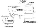
- FIG. 1the overall construction of an ultrasound diagnostic device will be described using FIG. 1 .
- an ultrasound diagnostic device 1comprises an ultrasound endoscope 2 , an ultrasound diagnostic signal processing device 11 and a monitor 12 and is arranged so as to be able to obtain an ultrasound diagnostic image by performing transmission/reception of ultrasound signals with respect to an intracavitary subject.
- the ultrasound endoscope 2comprises an insertion section 21 inserted into the body cavity, an operating section 22 and a connecting cord 23 .
- the ultrasound endoscope 2comprises an ultrasound probe 25 and a biopsy needle protrusion port 26 at a tip 24 of the insertion section 21 .
- the ultrasound endoscope 2is connected with the ultrasound diagnostic signal processing device 11 and performs transmission/reception of ultrasound signals with respect to the body by means of the ultrasound probe 25 .
- the ultrasound diagnostic signal processing device 11controls the ultrasound probe 25 of the ultrasound endoscope 2 and processes the signals obtained from the ultrasound probe 25 , and generates an ultrasound diagnostic image by known techniques and displays this on the monitor 12 .
- a biopsy needle insertion/retraction section 3is mounted on the operating section 22 of the ultrasound endoscope 2 .
- a biopsy needle insertion/retraction section 3is employed to insert/retract a biopsy needle 4 , which is a medical instrument, forward and backward.
- the biopsy needle 4is inserted from the biopsy needle insertion/retraction section 3 through the insertion section 21 of the ultrasound endoscope 2 so that the tip of the needle protrudes from the biopsy needle protrusion port 26 of the tip 24 of the insertion section 21 and so can pierce the aforesaid subject.
- the monitor 12displays an image corresponding to the ultrasound diagnostic image that is output from the ultrasound diagnostic signal processing device 11 .
- the ultrasound diagnostic signal processing device 11has a function whereby to superimpose the insertion boundaries of the piercing direction of the biopsy needle 4 on the display of the monitor 12 .
- the ultrasound probe 25 and biopsy needle protrusion port 26are provided at the tip 24 of the ultrasound endoscope 2 .
- An angle adjuster 27 for adjusting the angle with which the biopsy needle 4 protrudes from the tip of the ultrasound endoscope 2is provided in the interior of the biopsy needle protrusion port 26 .
- the angle adjuster 27is mounted in a condition in which it is rotatable by a rotary shaft 28 in a direction perpendicular to the longitudinal direction of the insertion section 21 .
- the angle adjuster 27is made capable of rotating between one and the other adjustment boundary positions by operation of the operating section 22 shown in FIG. 1 .
- FIG. 2shows with a solid line the case where the biopsy needle 4 in the one adjustment boundary position of the angle adjuster 27 protrudes from the tip 24 of the ultrasound endoscope 2 .
- the broken lineshows the position when the biopsy needle 4 is in the other adjustment boundary position.
- the angle adjuster 27 and biopsy needle 4are in the condition of smallest angle with respect to the longitudinal direction of the insertion section 21 .
- the angle with which the biopsy needle 4 protrudes from the tip 24 of the ultrasound endoscope 2depends on the type of ultrasound endoscope 2 and so the angle is a known quantity.
- FIG. 3the case where the biopsy needle 4 protrudes from the tip 24 of the ultrasound endoscope 2 in the aforesaid other adjustment boundary position of the angle adjuster 27 is indicated by a solid line.
- the broken lineindicates the position of the biopsy needle 4 at the one adjustment boundary position.
- the angle with respect to the longitudinal direction of the insertion section 21is largest.
- the angle with which the biopsy needle 4 protrudes from the tip 24 of the ultrasound endoscope 2is a known quantity.
- the angle adjuster 27is provided within the aforesaid insertion section 21 and has a function whereby to alter the direction of piercing of the aforesaid biopsy needle 4 by movement thereof.
- the ultrasound wave diagnostic signal processing device 11superimposes the movement range of this angle adjuster 27 on the ultrasound diagnostic image of the monitor 12 .
- FIG. 4illustrates an example of the construction of the biopsy needle insertion/retraction section 3 and the biopsy needle 4 .
- the biopsy needle insertion/retraction section 3comprises a biopsy needle insertion/retraction section casing 31 and a piston 32 .
- the biopsy needle 4is mounted on the piston 32 and is inserted/retracted with forward/backward movement of the piston 32 .
- the biopsy needle 4protrudes from the tip 24 of the ultrasound endoscope 2 when the operator pushes the piston 32 .
- the biopsy needle insertion/retraction section 3is not restricted to a biopsy needle insertion/retraction section of the construction shown in FIG. 4 . It would be possible to employ a biopsy needle insertion/retraction section provided with a stop for preventing pushing the end of the piston beyond a pre-set stroke, or a biopsy needle insertion/attraction section wherein the piston is advanced by a pre-set stroke by operation of a button.
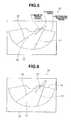
- FIG. 5shows an example of the display of an image which is output to the monitor 12 by the ultrasound diagnostic signal processing device 11 .
- a sector-shaped ultrasound diagnostic image 14is displayed on the screen 13 of the monitor 12 .
- the biopsy needle image 10is an ultrasound image corresponding to the biopsy needle 4 displayed on the ultrasound diagnostic image 14 and is displayed as a high-brightness echo of linear shape. Display or non-display of the biopsy guide 15 can be selected as desired; this display is superimposed on the ultrasound diagnostic image 14 when display is selected by a changeover switch (not shown) of the ultrasound diagnostic signal processing device 11 .
- the biopsy guide 15comprises biopsy guidelines 16 and 17 . When the angle adjuster 27 of the ultrasound endoscope 2 is in the one adjustment boundary position shown in FIG. 2, the biopsy guideline 16 coincides with the direction of the biopsy needle image 10 displayed on the ultrasound diagnostic image 14 .
- the biopsy guideline 16may be displayed in a direction coinciding with this direction.
- means for specifying the type of the ultrasound endoscope 2 connected theretocan easily be implemented using known techniques.
- the biopsy guideline 17likewise coincides with the direction in which the biopsy needle image 10 is displayed on the ultrasound diagnostic image 14 when the angle adjuster 27 of the ultrasound endoscope 2 shown in FIG. 3 is in the other adjustment boundary position. The biopsy needle 10 must therefore be displayed within the area defined by the biopsy guidelines 16 and 17 .
- graduations 18providing a scale of the length with which how deep the piston 32 should be pushed in are displayed on the biopsy guidelines 16 and 17 .
- dot marks 19may be displayed at prescribed intervals within the range defined by biopsy guidelines 16 and 17 as shown in FIG. 6 .
- the length of the biopsy needle image 10can easily be recognized by the operator even when the biopsy needle image 10 is remote from the biopsy guidelines 16 and 17 .
- biopsycan be performed confidently, since the operator can recognize the range through which the biopsy needle has advanced by using the display of the biopsy guide 15 , even in cases where the direction of the biopsy needle cannot be directly visually ascertained by the operator, such as in the case of an ultrasound endoscope.
- the length of advancecan be ascertained, wherever the diagnostic needle has advanced to within the biopsy guide range.
- FIG. 7 and FIG. 8structural elements which are the same as in the first embodiment shown in FIG. 1 to FIG. 6 are given the same reference symbols and further description thereof is omitted.
- an ultrasound diagnostic device 5comprises the ultrasound endoscope 2 , ultrasound diagnostic signal processing device 6 , biopsy needle insertion/retraction section 7 and monitor 12 .
- ultrasound diagnostic signal processing device 6can be combined with a biopsy insertion/retraction section 7 having a mechanism for detecting the maximum amount of protrusion of the biopsy needle 4 .
- the biopsy diagnostic signal processing device 6comprises a maximum protrusion amount detection section 61 , a biopsy guide display generating section 62 , an ultrasound image generating section 63 and a synthesis processing section 64 .
- the biopsy needle insertion/retraction section 7comprises a biopsy needle insertion/retraction section casing 71 , a piston 72 and a stop 73 .
- the biopsy needle 4is mounted on the piston 72 .
- the stop 73is mounted at the proximal end of the biopsy needle insertion/retraction casing 71 in a condition in which its position can be adjusted.
- the stop 73serves to prevent the piston 72 being pushed in by more than stroke set by position adjustment in advance.
- a sensor 74is incorporated in the stop 73 .
- the sensor 74outputs data corresponding to the fixed position of the stop 73 to the ultrasound diagnostic signal processing device 6 .
- the sensor 74is constituted by for example a sensor comprising an encoder that converts the amount of movement in the forward/backward direction of the stop 73 into the number of pulses to output, or a sensor wherein the resistance value of a variable resistance changes with forward/backward movement of the stop 73 and is converted into the amount of movement by detecting the voltage difference across the two ends of this variable resistance, or a magnetic sensor wherein the distance from the end of the piston 72 is measured by detecting the strength of magnetism formed by a magnet embedded in one end of the piston 72 .
- the data that is output by the sensor 74is input to the maximum protrusion amount detection section 61 within the ultrasound diagnostic signal processing device 6 .
- the maximum protrusion amount detection section 61detects the set position i.e. the maximum protrusion amount of the stop 73 using the data from the sensor 74 .
- the data of the detection result of the maximum protrusion amount detection section 61is sent to the biopsy guide display generating section 62 .
- the biopsy guide display generating section 62Based on the data from the maximum protrusion amount detection section 61 , the biopsy guide display generating section 62 generates an image of the biopsy guide with the utmost position reached by the biopsy needle, to be described below, attached thereto.
- the ultrasound image generating section 63processes the signal obtained from the ultrasound endoscope 2 , generates an ultrasound diagnostic image by known techniques and outputs this to the synthesis processing section 64 .
- the image of the biopsy guide with the utmost position reached by the biopsy needle attached thereto created by the biopsy guide display generating section 62is synthesized with the ultrasound diagnostic image generated by the ultrasound image generating section 63 in the synthesis processing section 64 and displayed on the monitor 12 .
- FIG. 8An example of the display of a biopsy guide with the utmost position reached by the biopsy needle attached thereto is illustrated using FIG. 8 .
- a biopsy guide 15is displayed on an ultrasound diagnostic image 14 of a screen 13 of the monitor 12 and, in addition, the utmost position 70 , constituting the aforesaid boundary of insertion in the piercing direction, that is reached by the biopsy needle is displayed.
- the utmost position 70 reached by the biopsy needleis displayed as an arcuate dotted line or solid line.
- the position of the stop 73is detected by the aforesaid construction and the utmost position 70 reached by the biopsy needle is updated by the movement interlocked with the movement of the stop 73 .
- the same benefits as in the case of the first embodiment illustrated in FIG. 1 to FIG. 6are obtained and, even in the case of a biopsy needle 4 wherein the stop position of the biopsy needle 4 can be altered, the utmost position reached by the biopsy needle 4 can be displayed being interlocked with the stop 73 which constitutes the stop mechanism of the mechanical biopsy needle 4 , so ease of the piercing operation can be improved, and the operator can perform a biopsy using the biopsy needle with confidence.
- biopsy guides used in the first and second embodimentsare not restricted to those illustrated in FIG. 5, FIG. 6 and FIG. 8 and the solid lines could be replaced by the dotted lines or the broken lines.
- the third embodimentaddresses these problems.
- FIG. 9 to FIG. 11structural elements which are the same as in the case of the first embodiment illustrated in FIG. 1 to FIG. 6 are given the same reference symbols and further description thereof is omitted. Also, portions which are not shown in FIG. 9 will be described with reference to FIG. 2 instead.
- an angle output section(not shown) that outputs an angle set by an angle adjuster 27 shown in FIG. 2 is built in an ultrasound endoscope 9 .
- the angle output sectionis integral with or constructed separately from the angle adjuster 27 of the tip 24 of the endoscope 2 shown in FIG. 2 and is arranged to output an angle set as a resistance value change etc produced by a variable resistor, or as a pulse output produced by an encoder.
- An ultrasound diagnostic signal processing device 100comprises an angle detection section 101 , a biopsy guide display generating section 102 , an ultrasound image generating section 103 and a synthesis processing section 104 .
- the data output from the angle output sectionis sent to the angle detection section 101 of the ultrasound diagnostic signal processing device 100 .
- the angle detection section 101calculates the angle of the angle adjuster 27 using the data sent from the angle output section.
- the angle of the angle adjuster 27 calculated by the angle detection section 101is sent to the biopsy guide display generating section 102 .
- the biopsy guide display generating section 102generates a biopsy guide, to be described.
- the ultrasound echo of the ultrasound endoscope 9is sent to the ultrasound image generating section 103 of the ultrasound diagnostic signal processing device 100 .
- the ultrasound image generating section 103generates an ultrasound diagnostic image using the ultrasound echo that is sent to it.
- the synthesis processing section 104synthesizes a biopsy guide generated by the biopsy guide display generating section 102 with the ultrasound diagnostic, image generated by the ultrasound image generating section 103 and outputs the result to the monitor 12 .
- FIG. 10shows an example of an image output to the monitor 12 by the ultrasound diagnostic signal processing device 100 .
- the ultrasound diagnostic signal processing device 100detects the angle of the angle adjuster 27 of the ultrasound endoscope 9 , a biopsy guide 85 displayed on the monitor 12 is displayed in a direction coinciding with the direction of insertion of a biopsy needle image 80 .
- the direction of the biopsy guide 85changes for example as shown in FIG. 11 .
- the separation of the biopsy guidelines 86 and 87is determined taking into account the accuracy of the angle output section incorporated in the ultrasound endoscope 9 and the calculation error of the angle detection section 101 .
- displayis effected with a width of the order of a few times to ten times that of the biopsy needle image 80 .
- dot marks 89may be displayed with a prescribed separation.
- the operator of the ultrasound endoscopewhen employing a biopsy needle whose direction of insertion can be varied, can reliably ascertain the direction of insertion of the biopsy needle by means of the biopsy guide 85 displayed on the monitor 12 and can therefore conduct biopsy with confidence.
- an ultrasound diagnostic device 111is made capable of displaying a biopsy guide coincident with the direction of insertion of the biopsy needle when combined with an ultrasound endoscope 2 that does not have an angle output section that outputs the angle of the angle adjuster.
- An ultrasound diagnostic signal processing device 120comprises a biopsy needle angle detection section 121 , a biopsy guide display generating section 122 , an ultrasound image generating section 123 and synthesis processing section 124 .
- the ultrasound diagnostic signal processing device 120generates an ultrasound diagnostic image with the ultrasound image generating section 123 using the ultrasound echoes from the ultrasound endoscope 2 .
- the biopsy needle angle detection section 121performs a calculation of the direction of the biopsy needle as follows, using the ultrasound diagnostic image generated by the ultrasound image generating section 123 .
- the biopsy needleis displayed as a linear high-brightness echo as the biopsy needle image 10 of FIG. 5 .
- the biopsy needle angle detection section 121performs detection by performing image processing to ascertain whether or not a high-brightness echo which is linear and not shorter than a prescribed length is present.
- the length of the linear echo that is used by the biopsy needle angle detection section 121 as a standard for deciding whether or not a biopsy needle image is presentis specified beforehand as about 1 cm, but the length of the linear echo constituting the standard for this decision can be set at the operator's discretion by using a switch, not shown, on the ultrasound diagnostic signal processing device 120 .
- the biopsy needle angle detection section 121does not detect a linear echo of at least the standard length, it decides that no biopsy needle is being displayed.
- the biopsy guide display generating section 122therefore displays on the monitor 12 a biopsy guide 15 having the biopsy guidelines 16 and 17 at both ends as adjustment boundary positions of the angle of the biopsy needle as in FIG. 5 or FIG. 6 . If the biopsy needle angle detection section 121 detect that a linear echo is not shorter than the standard length, it decides that the biopsy needle is present in the ultrasound diagnostic image and sends the result of calculation of its angle information to the biopsy guide display generating section 122 .
- the operatorcan ascertain by means of the biopsy guide displayed on the monitor 12 in what direction the biopsy needle is effecting piercing and so can conduct biopsy with confidence.
- the piercing ultrasound probe disclosed in Japanese Laid-open Patent Application No. H8-229042 or the position detection device of a piercing needle and ultrasound diagnostic device disclosed in Japanese Laid-open Patent Application No. H9-271472relate to inventions in which the tip position of the biopsy needle is detected and displayed. With these devices, the tip position of the biopsy needle can be specified, but the operator must take care to avoid contacting with blood vessels and so could not perform biopsy with confidence.
- the fifth embodimentaddresses this problem.
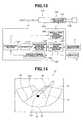
- FIG. 13 and FIG. 14structural elements which are same as in the case of the first embodiment shown in FIG. 1 to FIG. 6 are given the same reference symbols and further description thereof is omitted.
- an acoustic diagnostic device 131has a function of stopping the biopsy needle 4 .
- An acoustic diagnostic signal processing device 140comprises an acoustic image generating section 141 , blood flow position detection section 142 , memory 143 , comparison section 144 , needle position detection section 145 and needle stop signal generating section 146 .
- a biopsy needle insertion/retraction section 150comprises a biopsy needle insertion/retraction or section casing 151 , piston 152 and needle stop mechanism 153 .
- the acoustic diagnostic signal processing device 140outputs a needle stop signal from the needle stop signal generating section 146 by the method to be described.
- a needle stop mechanism 153 of the biopsy insertion/retraction section 150receives a needle stop signal from the needle stop signal generating section 146 .
- the needle stop mechanism 153locks the piston 152 with respect to the biopsy needle insertion/retraction section casing 151 so that it cannot move further in the pushing-in direction.
- the biopsy needle insertion/retraction section 150prevents further protrusion of the biopsy needle 4 .
- the ultrasound diagnostic signal processing device 140has a Doppler function like that of an ordinary ultrasound diagnostic device and this Doppler function is turned on when the needle stop signal is generated.
- the ultrasound image generating section 141displays a Doppler cursor 160 as shown in FIG. 14 on the monitor 12 , using the signal from the ultrasound endoscope 2 , and when blood flow is detected a blood flow information 161 is displayed.
- the blood flow position detection section 142 of the ultrasound diagnostic signal processing device 140stores the position data at which a Doppler signal is detected by the ultrasound image generating section 141 in the memory 143 and updates the position data stored in the memory 143 every time the position at which the Doppler signal was detected changes.
- the needle position detection section 145detects the linear high-brightness echo that is characteristic of a biopsy needle image 10 in which the biopsy needle 4 is drawn on the ultrasound diagnostic image 14 from the ultrasound diagnostic image of the ultrasound image generating section 141 by image processing and calculates the position corresponding to the tip of the biopsy needle 4 .
- the comparison section 144performs a comparison of the position data of a blood clot stored in the memory 143 with the position data of the tip of the biopsy needle 4 calculated by the needle position detection section 145 .
- an approach-avoidance distanceconstituting a criterion for the evaluation of the degree of proximity of the tip position of the biopsy needle 4 and the blood flow position is laid down; it outputs a needle stop signal to the needle stop signal generating section 146 if the tip position of the biopsy needle 4 and the blood flow position are within the approach-avoidance distance.
- the needle stop mechanism 153thereby locks and stops the biopsy needle 4 .
- the approach-avoidance distanceis set beforehand at about 1 cm; it can be altered at the operator's discretion using a switch, not shown, on the ultrasound diagnostic device.
- the biopsy guide 15is simultaneously displayed in FIG. 14, the biopsy guide 15 is not necessarily essential and it would be possible for the ultrasound diagnostic signal processing device 140 not to have a biopsy guide display function.
- the blood flow information 161is displayed and if the position of the tip of the biopsy needle 4 and the blood flow position are within the approach-avoidance distance, the biopsy needle 4 is stopped, so biopsy can be conducted with confidence.
- an ultrasound diagnostic device 171illustrates an ultrasound diagnostic device having a function of stopping the biopsy needle 4 of a different construction from that of FIG. 13 .
- An ultrasound diagnostic signal processing device 180comprises an ultrasound image generating section 181 , a blood flow position detection section 182 , a memory 183 , a comparison section 184 , a needle position detection section 185 , a needle stop signal generating section 186 , an angle detection section 187 and a needle protrusion amount detection section 188 .
- a biopsy needle insertion/retraction section 190comprises a biopsy needle insertion/retraction section casing 191 , piston 192 , needle stop mechanism 193 and protrusion amount output section 194 .
- the function of the needle stop mechanism 193is the same as that of the needle stop mechanism 153 in the biopsy needle insertion/retraction section 150 of FIG. 13 .
- the protrusion amount output section 194outputs data corresponding to the insertion/retraction position of the piston 192 with respect to the biopsy needle insertion/retraction section casing 191 obtained by means of a pulse output produced by an encoder, a variable resistance value produced by a variable resistor, magnetic intensity produced by a magnetic sensor or the like.
- the angle detection mechanism produced by the combination of the ultrasound endoscope 9 and the angle detection section 187is the same as the construction of the ultrasound diagnostic signal processing device 100 shown in FIG. 9 .
- the needle protrusion amount detection section 188calculates in real time the amount of protrusion of the biopsy needle 4 from the position data of the piston 192 obtained from the protrusion amount output section 194 .
- the needle position detection section 185calculates the tip position of the biopsy needle 4 from the amount of protrusion of the biopsy needle 4 calculated by the needle protrusion amount detection section 188 and the angle of the angle adjuster obtained by the angle adjustment section 187 .
- the detection of the blood flow position by the blood flow position detection section 182storing of the blood flow position data in the memory 183 and the construction, whereby the tip position of the biopsy needle 4 and the blood flow position are compared by the comparison section 184 and a needle stop signal is sent to the needle stop mechanism 193 of the biopsy needle insertion/retraction section 190 from the needle stop signal generating section 186 , are the same as in the case of the construction described referring to the ultrasound diagnostic signal processing device 140 of FIG. 13 .
- the biopsy needle 4is stopped when the position of the tip of the biopsy needle 4 and the blood flow position approach are within the approach/excursion distance, so biopsy can be conducted with confidence.
- the ultrasound probe of the embodiments shown in FIG. 1 to FIG. 15is not restricted to an ultrasound endoscope but could be combined with an ultrasound probe of the external type.
Landscapes
- Health & Medical Sciences (AREA)
- Life Sciences & Earth Sciences (AREA)
- Surgery (AREA)
- Heart & Thoracic Surgery (AREA)
- Molecular Biology (AREA)
- Radiology & Medical Imaging (AREA)
- Engineering & Computer Science (AREA)
- Biomedical Technology (AREA)
- Nuclear Medicine, Radiotherapy & Molecular Imaging (AREA)
- Medical Informatics (AREA)
- Pathology (AREA)
- Animal Behavior & Ethology (AREA)
- General Health & Medical Sciences (AREA)
- Public Health (AREA)
- Veterinary Medicine (AREA)
- Physics & Mathematics (AREA)
- Biophysics (AREA)
- Ultra Sonic Daignosis Equipment (AREA)
Abstract
Description
Claims (18)
Applications Claiming Priority (2)
| Application Number | Priority Date | Filing Date | Title |
|---|---|---|---|
| JP2001325433AJP2003126093A (en) | 2001-10-23 | 2001-10-23 | Ultrasonic diagnostic apparatus |
| JP2001-325433 | 2001-10-23 |
Publications (2)
| Publication Number | Publication Date |
|---|---|
| US20030078502A1 US20030078502A1 (en) | 2003-04-24 |
| US6786870B2true US6786870B2 (en) | 2004-09-07 |
Family
ID=19141995
Family Applications (1)
| Application Number | Title | Priority Date | Filing Date |
|---|---|---|---|
| US10/277,001Expired - LifetimeUS6786870B2 (en) | 2001-10-23 | 2002-10-21 | Device for examining a subject capable of marking a boundary range for insertion/retraction of an insertion/retraction member that is inserted in and retracted from the subject |
Country Status (4)
| Country | Link |
|---|---|
| US (1) | US6786870B2 (en) |
| EP (1) | EP1306054B1 (en) |
| JP (1) | JP2003126093A (en) |
| DE (1) | DE60226936D1 (en) |
Cited By (43)
| Publication number | Priority date | Publication date | Assignee | Title |
|---|---|---|---|---|
| US20070038089A1 (en)* | 2005-06-29 | 2007-02-15 | Olympus Medical Systems Corp. | Transurethral diagnostic method and treatment method using ultrasonic endoscope |
| US20080051657A1 (en)* | 2005-02-28 | 2008-02-28 | Rold Michael D | Systems And Methods For Estimating The Size And Position Of A Medical Device To Be Applied Within A Patient |
| US20110160588A1 (en)* | 2008-09-09 | 2011-06-30 | Olympus Medical Systems Corp. | Ultrasound image display apparatus and ultrasound image display method |
| US8088072B2 (en)* | 2007-10-12 | 2012-01-03 | Gynesonics, Inc. | Methods and systems for controlled deployment of needles in tissue |
| US20120143029A1 (en)* | 2007-11-26 | 2012-06-07 | Bard Access Systems, Inc. | Systems and methods for guiding a medical instrument |
| US8968210B2 (en) | 2008-10-01 | 2015-03-03 | Covidien LLP | Device for needle biopsy with integrated needle protection |
| US9125578B2 (en) | 2009-06-12 | 2015-09-08 | Bard Access Systems, Inc. | Apparatus and method for catheter navigation and tip location |
| EP2526869A3 (en)* | 2011-05-23 | 2015-10-07 | Fujifilm Corporation | Image processing device, radiographic image capture system, image processing method and image processing program storage medium |
| US9186128B2 (en) | 2008-10-01 | 2015-11-17 | Covidien Lp | Needle biopsy device |
| US20160001097A1 (en)* | 2013-02-25 | 2016-01-07 | Korust Co., Ltd. | Line-focused ultrasound transducer and high-intensity line focused ultrasound generator including same |
| US9265443B2 (en) | 2006-10-23 | 2016-02-23 | Bard Access Systems, Inc. | Method of locating the tip of a central venous catheter |
| US9332973B2 (en) | 2008-10-01 | 2016-05-10 | Covidien Lp | Needle biopsy device with exchangeable needle and integrated needle protection |
| US9339206B2 (en) | 2009-06-12 | 2016-05-17 | Bard Access Systems, Inc. | Adaptor for endovascular electrocardiography |
| US9345422B2 (en) | 2006-10-23 | 2016-05-24 | Bard Acess Systems, Inc. | Method of locating the tip of a central venous catheter |
| US9415188B2 (en) | 2010-10-29 | 2016-08-16 | C. R. Bard, Inc. | Bioimpedance-assisted placement of a medical device |
| US9445734B2 (en) | 2009-06-12 | 2016-09-20 | Bard Access Systems, Inc. | Devices and methods for endovascular electrography |
| US9456766B2 (en) | 2007-11-26 | 2016-10-04 | C. R. Bard, Inc. | Apparatus for use with needle insertion guidance system |
| US9492097B2 (en) | 2007-11-26 | 2016-11-15 | C. R. Bard, Inc. | Needle length determination and calibration for insertion guidance system |
| US9526440B2 (en) | 2007-11-26 | 2016-12-27 | C.R. Bard, Inc. | System for placement of a catheter including a signal-generating stylet |
| US9532724B2 (en) | 2009-06-12 | 2017-01-03 | Bard Access Systems, Inc. | Apparatus and method for catheter navigation using endovascular energy mapping |
| US9549685B2 (en) | 2007-11-26 | 2017-01-24 | C. R. Bard, Inc. | Apparatus and display methods relating to intravascular placement of a catheter |
| US9554716B2 (en) | 2007-11-26 | 2017-01-31 | C. R. Bard, Inc. | Insertion guidance system for needles and medical components |
| US9636031B2 (en) | 2007-11-26 | 2017-05-02 | C.R. Bard, Inc. | Stylets for use with apparatus for intravascular placement of a catheter |
| US9649048B2 (en) | 2007-11-26 | 2017-05-16 | C. R. Bard, Inc. | Systems and methods for breaching a sterile field for intravascular placement of a catheter |
| US9681823B2 (en) | 2007-11-26 | 2017-06-20 | C. R. Bard, Inc. | Integrated system for intravascular placement of a catheter |
| US9782565B2 (en) | 2008-10-01 | 2017-10-10 | Covidien Lp | Endoscopic ultrasound-guided biliary access system |
| US9839372B2 (en) | 2014-02-06 | 2017-12-12 | C. R. Bard, Inc. | Systems and methods for guidance and placement of an intravascular device |
| US9901714B2 (en) | 2008-08-22 | 2018-02-27 | C. R. Bard, Inc. | Catheter assembly including ECG sensor and magnetic assemblies |
| US9907513B2 (en) | 2008-10-07 | 2018-03-06 | Bard Access Systems, Inc. | Percutaneous magnetic gastrostomy |
| US10004875B2 (en) | 2005-08-24 | 2018-06-26 | C. R. Bard, Inc. | Stylet apparatuses and methods of manufacture |
| US10046139B2 (en) | 2010-08-20 | 2018-08-14 | C. R. Bard, Inc. | Reconfirmation of ECG-assisted catheter tip placement |
| US10349890B2 (en) | 2015-06-26 | 2019-07-16 | C. R. Bard, Inc. | Connector interface for ECG-based catheter positioning system |
| US10449330B2 (en) | 2007-11-26 | 2019-10-22 | C. R. Bard, Inc. | Magnetic element-equipped needle assemblies |
| US10485513B2 (en) | 2011-01-31 | 2019-11-26 | Analogic Corporation | Ultrasound imaging apparatus |
| US10524691B2 (en) | 2007-11-26 | 2020-01-07 | C. R. Bard, Inc. | Needle assembly including an aligned magnetic element |
| US10610195B2 (en) | 2010-09-20 | 2020-04-07 | Soma Research, Llc | Probe and system for use with an ultrasound device |
| US10751509B2 (en) | 2007-11-26 | 2020-08-25 | C. R. Bard, Inc. | Iconic representations for guidance of an indwelling medical device |
| US10973584B2 (en) | 2015-01-19 | 2021-04-13 | Bard Access Systems, Inc. | Device and method for vascular access |
| US10992079B2 (en) | 2018-10-16 | 2021-04-27 | Bard Access Systems, Inc. | Safety-equipped connection systems and methods thereof for establishing electrical connections |
| US10993770B2 (en) | 2016-11-11 | 2021-05-04 | Gynesonics, Inc. | Controlled treatment of tissue and dynamic interaction with, and comparison of, tissue and/or treatment data |
| US11000207B2 (en) | 2016-01-29 | 2021-05-11 | C. R. Bard, Inc. | Multiple coil system for tracking a medical device |
| US11298113B2 (en) | 2008-10-01 | 2022-04-12 | Covidien Lp | Device for needle biopsy with integrated needle protection |
| US11918300B2 (en) | 2018-01-23 | 2024-03-05 | Koninklijke Philips N.V. | Ultrasound imaging system providing needle insertion guidance |
Families Citing this family (51)
| Publication number | Priority date | Publication date | Assignee | Title |
|---|---|---|---|---|
| US8137279B2 (en) | 2001-10-16 | 2012-03-20 | Envisioneering, Llc | Scanning probe |
| US20050159676A1 (en)* | 2003-08-13 | 2005-07-21 | Taylor James D. | Targeted biopsy delivery system |
| JP4537698B2 (en)* | 2003-12-25 | 2010-09-01 | 株式会社東芝 | Ultrasonic diagnostic equipment |
| JP2005253742A (en)* | 2004-03-12 | 2005-09-22 | Matsushita Electric Ind Co Ltd | Ultrasonic diagnostic equipment |
| US8795195B2 (en)* | 2004-11-29 | 2014-08-05 | Senorx, Inc. | Graphical user interface for tissue biopsy system |
| US7835785B2 (en)* | 2005-10-04 | 2010-11-16 | Ascension Technology Corporation | DC magnetic-based position and orientation monitoring system for tracking medical instruments |
| JP4789644B2 (en)* | 2006-02-14 | 2011-10-12 | 株式会社日立メディコ | Ultrasonic diagnostic equipment |
| JP4958455B2 (en)* | 2006-03-10 | 2012-06-20 | 株式会社日立メディコ | Ultrasonic diagnostic equipment |
| WO2007110076A1 (en)* | 2006-03-24 | 2007-10-04 | B-K Medical Aps | Biopsy system |
| US20080097218A1 (en)* | 2006-08-24 | 2008-04-24 | Boston Scientific Scimed, Inc. | Blood vessel puncture locating apparatus and method |
| JP2008253524A (en)* | 2007-04-04 | 2008-10-23 | Olympus Medical Systems Corp | Ultrasonic observation system |
| JP5060204B2 (en)* | 2007-08-13 | 2012-10-31 | 株式会社東芝 | Ultrasonic diagnostic apparatus and program |
| US20090247876A1 (en)* | 2008-03-28 | 2009-10-01 | Cannon Jr Charles W | Laparoscopic probe guidance system |
| KR101495768B1 (en) | 2008-04-29 | 2015-02-25 | 삼성전자 주식회사 | Image guided syringe apparatus and method for medical service |
| US8761862B2 (en) | 2009-10-09 | 2014-06-24 | Stephen F. Ridley | Ultrasound guided probe device and sterilizable shield for same |
| US9044216B2 (en) | 2010-07-12 | 2015-06-02 | Best Medical International, Inc. | Biopsy needle assembly |
| US8758256B2 (en) | 2010-07-12 | 2014-06-24 | Best Medical International, Inc. | Apparatus for brachytherapy that uses a scanning probe for treatment of malignant tissue |
| JP5743329B2 (en)* | 2012-01-19 | 2015-07-01 | ジーイー・メディカル・システムズ・グローバル・テクノロジー・カンパニー・エルエルシー | Ultrasonic diagnostic apparatus and control program therefor |
| EP2836133B1 (en)* | 2012-04-10 | 2018-08-29 | The Johns Hopkins University | Cohesive robot-ultrasound probe for prostate biopsy |
| CN104519806B (en) | 2012-08-03 | 2016-07-06 | 查尔斯·沃尔特 | Endoscopic biopsy instrument, endoscope, and method of obtaining a biopsy sample |
| JP6309240B2 (en)* | 2012-10-26 | 2018-04-11 | キヤノンメディカルシステムズ株式会社 | Ultrasonic diagnostic equipment |
| US10274553B2 (en) | 2013-03-15 | 2019-04-30 | Canon U.S.A., Inc. | Needle placement manipulator with attachment for RF-coil |
| JP5636467B2 (en)* | 2013-04-22 | 2014-12-03 | 日立アロカメディカル株式会社 | Ultrasonic diagnostic equipment |
| CA2911661C (en)* | 2013-05-08 | 2021-06-01 | Clph, Llc | Catheters and dilators for trans-septal procedures and methods for making and using them |
| JP6305810B2 (en)* | 2014-03-31 | 2018-04-04 | キヤノンメディカルシステムズ株式会社 | Medical diagnostic imaging equipment |
| CN104161546A (en)* | 2014-09-05 | 2014-11-26 | 深圳先进技术研究院 | Ultrasonic probe calibration system and method based on locatable puncture needle |
| JP7045664B2 (en) | 2014-09-12 | 2022-04-01 | ザ ブリガム アンド ウィメンズ ホスピタル インコーポレイテッド | Needle positioning device |
| US10292571B2 (en) | 2015-02-23 | 2019-05-21 | Uroviu Corporation | Handheld surgical endoscope with wide field of view (FOV) and illumination brightness adjusted by area within the FOV |
| US10869592B2 (en) | 2015-02-23 | 2020-12-22 | Uroviu Corp. | Handheld surgical endoscope |
| WO2016137838A1 (en) | 2015-02-23 | 2016-09-01 | Xiaolong Ouyang | Handheld surgical endoscope |
| US10524636B2 (en) | 2015-02-23 | 2020-01-07 | Uroviu Corp. | Handheld surgical endoscope |
| JP6843073B2 (en)* | 2015-05-18 | 2021-03-17 | コーニンクレッカ フィリップス エヌ ヴェKoninklijke Philips N.V. | Accuracy feedback during procedure for image-guided biopsy |
| US10639065B2 (en)* | 2015-07-21 | 2020-05-05 | Canon U.S.A., Inc. | Medical assist device |
| WO2017132505A1 (en) | 2016-01-29 | 2017-08-03 | Canon U.S.A., Inc. | Tool placement manipulator |
| JP6778028B2 (en)* | 2016-06-23 | 2020-10-28 | 株式会社日立製作所 | Medical system and ultrasonic diagnostic equipment |
| US11832797B2 (en) | 2016-09-25 | 2023-12-05 | Micronvision Corp. | Endoscopic fluorescence imaging |
| US11684248B2 (en) | 2017-09-25 | 2023-06-27 | Micronvision Corp. | Endoscopy/stereo colposcopy medical instrument |
| US11534243B2 (en)* | 2016-11-23 | 2022-12-27 | Clear Guide Medical, Inc. | System and methods for navigating interventional instrumentation |
| EP3551085A1 (en)* | 2016-12-07 | 2019-10-16 | Boston Scientific Scimed, Inc. | Systems for real-time biopsy needle and target tissue visualization |
| WO2018136950A1 (en)* | 2017-01-23 | 2018-07-26 | Uroviu Corporation | Handheld surgical endoscope |
| US12268358B2 (en) | 2019-12-05 | 2025-04-08 | Uroviu Corp. | Portable endoscope with side-mountable disposable portion |
| US11771304B1 (en) | 2020-11-12 | 2023-10-03 | Micronvision Corp. | Minimally invasive endoscope |
| US11980342B2 (en) | 2020-11-12 | 2024-05-14 | Micronvision Corp. | Minimally invasive endoscope |
| EP3566670A1 (en) | 2018-05-07 | 2019-11-13 | Koninklijke Philips N.V. | Safety system for surgical robot |
| EP4609800A2 (en)* | 2019-07-23 | 2025-09-03 | FUJI-FILM Corporation | Ultrasonic diagnostic device and method for controlling ultrasonic diagnostic device |
| EP4003138A4 (en) | 2019-07-25 | 2023-08-30 | Uroviu Corp. | DISPOSABLE ENDOSCOPY NEEDLE WITH INTEGRATED GRIPPER |
| WO2021019851A1 (en)* | 2019-07-26 | 2021-02-04 | 富士フイルム株式会社 | Measurement device, ultrasonic diagnostic device, measurement method, measurement program |
| JP7259052B2 (en)* | 2019-08-16 | 2023-04-17 | 富士フイルム株式会社 | ULTRASOUND DIAGNOSTIC SYSTEM AND CONTROL METHOD OF ULTRASOUND DIAGNOSTIC SYSTEM |
| CN113317850B (en)* | 2021-05-14 | 2023-01-13 | 上海埃尔顿医疗器械有限公司 | Ultrasonic biopsy needle |
| JP7544945B1 (en)* | 2023-03-16 | 2024-09-03 | オリンパス株式会社 | ENDOSCOPYRIGHT: 20100236644 |
| CN119157632A (en)* | 2023-12-26 | 2024-12-20 | 常州联影智融医疗科技有限公司 | Puncture path planning method, device, equipment and endoscope system |
Citations (14)
| Publication number | Priority date | Publication date | Assignee | Title |
|---|---|---|---|---|
| US4346717A (en)* | 1979-09-07 | 1982-08-31 | Siemens Aktiengesellschaft | Device for punctuating internal body organs, vessels or the like |
| US4567896A (en)* | 1984-01-20 | 1986-02-04 | Elscint, Inc. | Method and apparatus for calibrating a biopsy attachment for ultrasonic imaging apparatus |
| US4671292A (en)* | 1985-04-30 | 1987-06-09 | Dymax Corporation | Concentric biopsy probe |
| JPH03173542A (en) | 1989-11-30 | 1991-07-26 | Shimadzu Corp | Puncture adapter for ultrasound probe |
| JPH05176922A (en) | 1991-12-27 | 1993-07-20 | Shimadzu Corp | Ultrasonic diagnostic device |
| JPH08229042A (en) | 1995-02-24 | 1996-09-10 | Fuji Photo Optical Co Ltd | Piercing ultrasonic probe |
| JPH08299344A (en) | 1995-05-01 | 1996-11-19 | Aloka Co Ltd | Ultrasonic diagnostic device |
| JPH09122067A (en) | 1995-10-31 | 1997-05-13 | Olympus Optical Co Ltd | Ultrasonic endoscope |
| JPH09271472A (en) | 1996-04-04 | 1997-10-21 | Ge Yokogawa Medical Syst Ltd | Position detector for punctual needle and ultrasonic diagnostic system |
| US5967985A (en)* | 1997-07-15 | 1999-10-19 | Fujitsu Limited | Ultrasonic diagnostic apparatus |
| US6063031A (en)* | 1997-10-14 | 2000-05-16 | Assurance Medical, Inc. | Diagnosis and treatment of tissue with instruments |
| JP3173542B2 (en) | 1993-10-22 | 2001-06-04 | ダイハツ工業株式会社 | Oil component separation equipment |
| US6616610B2 (en)* | 2000-11-16 | 2003-09-09 | Ge Medical Systems Kretztechnik Gmbh & Co. Ohg | Method for determination of the direction of introduction and for controlling the introduction path of biopsy needles |
| US6733458B1 (en)* | 2001-09-25 | 2004-05-11 | Acuson Corporation | Diagnostic medical ultrasound systems and methods using image based freehand needle guidance |
Family Cites Families (4)
| Publication number | Priority date | Publication date | Assignee | Title |
|---|---|---|---|---|
| US4763662A (en)* | 1985-06-07 | 1988-08-16 | Olympus Optical Co., Ltd. | Ultrasonic biopsy endoscope with extensible guide sheath |
| US6019724A (en)* | 1995-02-22 | 2000-02-01 | Gronningsaeter; Aage | Method for ultrasound guidance during clinical procedures |
| KR19990029038A (en)* | 1995-07-16 | 1999-04-15 | 요아브 빨띠에리 | Free aiming of needle ceramic |
| JP4450873B2 (en)* | 1995-10-13 | 2010-04-14 | オリンパス株式会社 | Endoscopic puncture needle operation assist device |
- 2001
- 2001-10-23JPJP2001325433Apatent/JP2003126093A/enactivePending
- 2002
- 2002-10-21USUS10/277,001patent/US6786870B2/ennot_activeExpired - Lifetime
- 2002-10-22DEDE60226936Tpatent/DE60226936D1/ennot_activeExpired - Lifetime
- 2002-10-22EPEP02023670Apatent/EP1306054B1/ennot_activeExpired - Lifetime
Patent Citations (15)
| Publication number | Priority date | Publication date | Assignee | Title |
|---|---|---|---|---|
| US4346717A (en)* | 1979-09-07 | 1982-08-31 | Siemens Aktiengesellschaft | Device for punctuating internal body organs, vessels or the like |
| US4567896A (en)* | 1984-01-20 | 1986-02-04 | Elscint, Inc. | Method and apparatus for calibrating a biopsy attachment for ultrasonic imaging apparatus |
| US4671292A (en)* | 1985-04-30 | 1987-06-09 | Dymax Corporation | Concentric biopsy probe |
| JPH03173542A (en) | 1989-11-30 | 1991-07-26 | Shimadzu Corp | Puncture adapter for ultrasound probe |
| JPH05176922A (en) | 1991-12-27 | 1993-07-20 | Shimadzu Corp | Ultrasonic diagnostic device |
| JP3173542B2 (en) | 1993-10-22 | 2001-06-04 | ダイハツ工業株式会社 | Oil component separation equipment |
| JPH08229042A (en) | 1995-02-24 | 1996-09-10 | Fuji Photo Optical Co Ltd | Piercing ultrasonic probe |
| JPH08299344A (en) | 1995-05-01 | 1996-11-19 | Aloka Co Ltd | Ultrasonic diagnostic device |
| JPH09122067A (en) | 1995-10-31 | 1997-05-13 | Olympus Optical Co Ltd | Ultrasonic endoscope |
| JPH09271472A (en) | 1996-04-04 | 1997-10-21 | Ge Yokogawa Medical Syst Ltd | Position detector for punctual needle and ultrasonic diagnostic system |
| US5967985A (en)* | 1997-07-15 | 1999-10-19 | Fujitsu Limited | Ultrasonic diagnostic apparatus |
| US6221016B1 (en)* | 1997-07-15 | 2001-04-24 | Fujitsu Limited | Ultrasonic diagnostic apparatus |
| US6063031A (en)* | 1997-10-14 | 2000-05-16 | Assurance Medical, Inc. | Diagnosis and treatment of tissue with instruments |
| US6616610B2 (en)* | 2000-11-16 | 2003-09-09 | Ge Medical Systems Kretztechnik Gmbh & Co. Ohg | Method for determination of the direction of introduction and for controlling the introduction path of biopsy needles |
| US6733458B1 (en)* | 2001-09-25 | 2004-05-11 | Acuson Corporation | Diagnostic medical ultrasound systems and methods using image based freehand needle guidance |
Cited By (85)
| Publication number | Priority date | Publication date | Assignee | Title |
|---|---|---|---|---|
| US20080051657A1 (en)* | 2005-02-28 | 2008-02-28 | Rold Michael D | Systems And Methods For Estimating The Size And Position Of A Medical Device To Be Applied Within A Patient |
| US7892177B2 (en) | 2005-02-28 | 2011-02-22 | Scimed Life Systems, Inc. | Systems and methods for estimating the length and position of a stent to be applied within a patient |
| US8025622B2 (en) | 2005-02-28 | 2011-09-27 | Boston Scientific Scimed, Inc. | Systems and methods for estimating the size and position of a medical device to be applied within a patient |
| US8529455B2 (en) | 2005-02-28 | 2013-09-10 | Boston Scientific Scimed, Inc. | Systems and methods for estimating the size and position of a medical device to be applied within a patient |
| US20070038089A1 (en)* | 2005-06-29 | 2007-02-15 | Olympus Medical Systems Corp. | Transurethral diagnostic method and treatment method using ultrasonic endoscope |
| US11207496B2 (en) | 2005-08-24 | 2021-12-28 | C. R. Bard, Inc. | Stylet apparatuses and methods of manufacture |
| US10004875B2 (en) | 2005-08-24 | 2018-06-26 | C. R. Bard, Inc. | Stylet apparatuses and methods of manufacture |
| US9833169B2 (en) | 2006-10-23 | 2017-12-05 | Bard Access Systems, Inc. | Method of locating the tip of a central venous catheter |
| US9265443B2 (en) | 2006-10-23 | 2016-02-23 | Bard Access Systems, Inc. | Method of locating the tip of a central venous catheter |
| US9345422B2 (en) | 2006-10-23 | 2016-05-24 | Bard Acess Systems, Inc. | Method of locating the tip of a central venous catheter |
| US20120316440A1 (en)* | 2007-10-12 | 2012-12-13 | Gynesonics, Inc. | Methods and systems for controlled deployment of needles in tissue |
| US11096760B2 (en) | 2007-10-12 | 2021-08-24 | Gynesonics, Inc. | Methods and systems for controlled deployment of needles in tissue |
| US11096761B2 (en) | 2007-10-12 | 2021-08-24 | Gynesonics, Inc. | Methods and systems for controlled deployment of needles in tissue |
| US8262577B2 (en) | 2007-10-12 | 2012-09-11 | Gynesonics, Inc. | Methods and systems for controlled deployment of needles in tissue |
| US11826207B2 (en) | 2007-10-12 | 2023-11-28 | Gynesonics, Inc | Methods and systems for controlled deployment of needles in tissue |
| US8088072B2 (en)* | 2007-10-12 | 2012-01-03 | Gynesonics, Inc. | Methods and systems for controlled deployment of needles in tissue |
| US11925512B2 (en) | 2007-10-12 | 2024-03-12 | Gynesonics, Inc. | Methods and systems for controlled deployment of needles in tissue |
| US10165962B2 (en) | 2007-11-26 | 2019-01-01 | C. R. Bard, Inc. | Integrated systems for intravascular placement of a catheter |
| US10238418B2 (en) | 2007-11-26 | 2019-03-26 | C. R. Bard, Inc. | Apparatus for use with needle insertion guidance system |
| US10751509B2 (en) | 2007-11-26 | 2020-08-25 | C. R. Bard, Inc. | Iconic representations for guidance of an indwelling medical device |
| US20120143029A1 (en)* | 2007-11-26 | 2012-06-07 | Bard Access Systems, Inc. | Systems and methods for guiding a medical instrument |
| US9456766B2 (en) | 2007-11-26 | 2016-10-04 | C. R. Bard, Inc. | Apparatus for use with needle insertion guidance system |
| US9492097B2 (en) | 2007-11-26 | 2016-11-15 | C. R. Bard, Inc. | Needle length determination and calibration for insertion guidance system |
| US9521961B2 (en)* | 2007-11-26 | 2016-12-20 | C. R. Bard, Inc. | Systems and methods for guiding a medical instrument |
| US9526440B2 (en) | 2007-11-26 | 2016-12-27 | C.R. Bard, Inc. | System for placement of a catheter including a signal-generating stylet |
| US11779240B2 (en) | 2007-11-26 | 2023-10-10 | C. R. Bard, Inc. | Systems and methods for breaching a sterile field for intravascular placement of a catheter |
| US9549685B2 (en) | 2007-11-26 | 2017-01-24 | C. R. Bard, Inc. | Apparatus and display methods relating to intravascular placement of a catheter |
| US9554716B2 (en) | 2007-11-26 | 2017-01-31 | C. R. Bard, Inc. | Insertion guidance system for needles and medical components |
| US9636031B2 (en) | 2007-11-26 | 2017-05-02 | C.R. Bard, Inc. | Stylets for use with apparatus for intravascular placement of a catheter |
| US9649048B2 (en) | 2007-11-26 | 2017-05-16 | C. R. Bard, Inc. | Systems and methods for breaching a sterile field for intravascular placement of a catheter |
| US9681823B2 (en) | 2007-11-26 | 2017-06-20 | C. R. Bard, Inc. | Integrated system for intravascular placement of a catheter |
| US10602958B2 (en) | 2007-11-26 | 2020-03-31 | C. R. Bard, Inc. | Systems and methods for guiding a medical instrument |
| US10524691B2 (en) | 2007-11-26 | 2020-01-07 | C. R. Bard, Inc. | Needle assembly including an aligned magnetic element |
| US11707205B2 (en) | 2007-11-26 | 2023-07-25 | C. R. Bard, Inc. | Integrated system for intravascular placement of a catheter |
| US10966630B2 (en) | 2007-11-26 | 2021-04-06 | C. R. Bard, Inc. | Integrated system for intravascular placement of a catheter |
| US11529070B2 (en) | 2007-11-26 | 2022-12-20 | C. R. Bard, Inc. | System and methods for guiding a medical instrument |
| US10449330B2 (en) | 2007-11-26 | 2019-10-22 | C. R. Bard, Inc. | Magnetic element-equipped needle assemblies |
| US9999371B2 (en) | 2007-11-26 | 2018-06-19 | C. R. Bard, Inc. | Integrated system for intravascular placement of a catheter |
| US10342575B2 (en) | 2007-11-26 | 2019-07-09 | C. R. Bard, Inc. | Apparatus for use with needle insertion guidance system |
| US11123099B2 (en) | 2007-11-26 | 2021-09-21 | C. R. Bard, Inc. | Apparatus for use with needle insertion guidance system |
| US10849695B2 (en) | 2007-11-26 | 2020-12-01 | C. R. Bard, Inc. | Systems and methods for breaching a sterile field for intravascular placement of a catheter |
| US10105121B2 (en) | 2007-11-26 | 2018-10-23 | C. R. Bard, Inc. | System for placement of a catheter including a signal-generating stylet |
| US10231753B2 (en) | 2007-11-26 | 2019-03-19 | C. R. Bard, Inc. | Insertion guidance system for needles and medical components |
| US11134915B2 (en) | 2007-11-26 | 2021-10-05 | C. R. Bard, Inc. | System for placement of a catheter including a signal-generating stylet |
| US11027101B2 (en) | 2008-08-22 | 2021-06-08 | C. R. Bard, Inc. | Catheter assembly including ECG sensor and magnetic assemblies |
| US9901714B2 (en) | 2008-08-22 | 2018-02-27 | C. R. Bard, Inc. | Catheter assembly including ECG sensor and magnetic assemblies |
| US20110160588A1 (en)* | 2008-09-09 | 2011-06-30 | Olympus Medical Systems Corp. | Ultrasound image display apparatus and ultrasound image display method |
| US9186128B2 (en) | 2008-10-01 | 2015-11-17 | Covidien Lp | Needle biopsy device |
| US10076316B2 (en) | 2008-10-01 | 2018-09-18 | Covidien Lp | Needle biopsy device |
| US8968210B2 (en) | 2008-10-01 | 2015-03-03 | Covidien LLP | Device for needle biopsy with integrated needle protection |
| US11298113B2 (en) | 2008-10-01 | 2022-04-12 | Covidien Lp | Device for needle biopsy with integrated needle protection |
| US11039816B2 (en) | 2008-10-01 | 2021-06-22 | Covidien Lp | Needle biopsy device with exchangeable needle and integrated needle protection |
| US9913630B2 (en) | 2008-10-01 | 2018-03-13 | Covidien Lp | Device for needle biopsy with integrated needle protection |
| US9332973B2 (en) | 2008-10-01 | 2016-05-10 | Covidien Lp | Needle biopsy device with exchangeable needle and integrated needle protection |
| US9782565B2 (en) | 2008-10-01 | 2017-10-10 | Covidien Lp | Endoscopic ultrasound-guided biliary access system |
| US10888689B2 (en) | 2008-10-01 | 2021-01-12 | Covidien Lp | Endoscopic ultrasound-guided biliary access system |
| US9907513B2 (en) | 2008-10-07 | 2018-03-06 | Bard Access Systems, Inc. | Percutaneous magnetic gastrostomy |
| US10912488B2 (en) | 2009-06-12 | 2021-02-09 | Bard Access Systems, Inc. | Apparatus and method for catheter navigation and tip location |
| US9339206B2 (en) | 2009-06-12 | 2016-05-17 | Bard Access Systems, Inc. | Adaptor for endovascular electrocardiography |
| US9532724B2 (en) | 2009-06-12 | 2017-01-03 | Bard Access Systems, Inc. | Apparatus and method for catheter navigation using endovascular energy mapping |
| US11419517B2 (en) | 2009-06-12 | 2022-08-23 | Bard Access Systems, Inc. | Apparatus and method for catheter navigation using endovascular energy mapping |
| US9445734B2 (en) | 2009-06-12 | 2016-09-20 | Bard Access Systems, Inc. | Devices and methods for endovascular electrography |
| US10231643B2 (en) | 2009-06-12 | 2019-03-19 | Bard Access Systems, Inc. | Apparatus and method for catheter navigation and tip location |
| US10271762B2 (en) | 2009-06-12 | 2019-04-30 | Bard Access Systems, Inc. | Apparatus and method for catheter navigation using endovascular energy mapping |
| US9125578B2 (en) | 2009-06-12 | 2015-09-08 | Bard Access Systems, Inc. | Apparatus and method for catheter navigation and tip location |
| US10046139B2 (en) | 2010-08-20 | 2018-08-14 | C. R. Bard, Inc. | Reconfirmation of ECG-assisted catheter tip placement |
| US11045165B2 (en) | 2010-09-20 | 2021-06-29 | Soma Research, Llc | Probe and system for use with an ultrasound device |
| US10610195B2 (en) | 2010-09-20 | 2020-04-07 | Soma Research, Llc | Probe and system for use with an ultrasound device |
| US9415188B2 (en) | 2010-10-29 | 2016-08-16 | C. R. Bard, Inc. | Bioimpedance-assisted placement of a medical device |
| US10485513B2 (en) | 2011-01-31 | 2019-11-26 | Analogic Corporation | Ultrasound imaging apparatus |
| EP2526869A3 (en)* | 2011-05-23 | 2015-10-07 | Fujifilm Corporation | Image processing device, radiographic image capture system, image processing method and image processing program storage medium |
| US10363440B2 (en)* | 2013-02-25 | 2019-07-30 | Korust Co., Ltd. | Line-focused ultrasound transducer and high-intensity line focused ultrasound generator including same |
| US20160001097A1 (en)* | 2013-02-25 | 2016-01-07 | Korust Co., Ltd. | Line-focused ultrasound transducer and high-intensity line focused ultrasound generator including same |
| US10863920B2 (en) | 2014-02-06 | 2020-12-15 | C. R. Bard, Inc. | Systems and methods for guidance and placement of an intravascular device |
| US9839372B2 (en) | 2014-02-06 | 2017-12-12 | C. R. Bard, Inc. | Systems and methods for guidance and placement of an intravascular device |
| US10973584B2 (en) | 2015-01-19 | 2021-04-13 | Bard Access Systems, Inc. | Device and method for vascular access |
| US10349890B2 (en) | 2015-06-26 | 2019-07-16 | C. R. Bard, Inc. | Connector interface for ECG-based catheter positioning system |
| US11026630B2 (en) | 2015-06-26 | 2021-06-08 | C. R. Bard, Inc. | Connector interface for ECG-based catheter positioning system |
| US11000207B2 (en) | 2016-01-29 | 2021-05-11 | C. R. Bard, Inc. | Multiple coil system for tracking a medical device |
| US11419682B2 (en) | 2016-11-11 | 2022-08-23 | Gynesonics, Inc. | Controlled treatment of tissue and dynamic interaction with, and comparison of, tissue and/or treatment data |
| US10993770B2 (en) | 2016-11-11 | 2021-05-04 | Gynesonics, Inc. | Controlled treatment of tissue and dynamic interaction with, and comparison of, tissue and/or treatment data |
| US12239382B2 (en) | 2016-11-11 | 2025-03-04 | Gynesonics, Inc. | Controlled treatment of tissue and dynamic interaction with, and comparison of, tissue and/or treatment data |
| US11918300B2 (en) | 2018-01-23 | 2024-03-05 | Koninklijke Philips N.V. | Ultrasound imaging system providing needle insertion guidance |
| US11621518B2 (en) | 2018-10-16 | 2023-04-04 | Bard Access Systems, Inc. | Safety-equipped connection systems and methods thereof for establishing electrical connections |
| US10992079B2 (en) | 2018-10-16 | 2021-04-27 | Bard Access Systems, Inc. | Safety-equipped connection systems and methods thereof for establishing electrical connections |
Also Published As
| Publication number | Publication date |
|---|---|
| DE60226936D1 (en) | 2008-07-17 |
| JP2003126093A (en) | 2003-05-07 |
| EP1306054A3 (en) | 2004-01-14 |
| US20030078502A1 (en) | 2003-04-24 |
| EP1306054A2 (en) | 2003-05-02 |
| EP1306054B1 (en) | 2008-06-04 |
Similar Documents
| Publication | Publication Date | Title |
|---|---|---|
| US6786870B2 (en) | Device for examining a subject capable of marking a boundary range for insertion/retraction of an insertion/retraction member that is inserted in and retracted from the subject | |
| EP4251063B1 (en) | Ultrasound probe with target tracking capability | |
| US5257628A (en) | Ultrasound internal examination system | |
| EP2147636B1 (en) | Device and method for guiding surgical tools by ultrasonic imaging | |
| US9539026B2 (en) | Needle guide and method for determining the position of a needle | |
| US20230355078A1 (en) | Detection system and method for automatic detection of surgical instruments | |
| EP3454757B1 (en) | 3d tracking of an interventional instrument in 2d ultrasound guided interventions | |
| US10390728B2 (en) | Medical image diagnosis apparatus | |
| JP4365841B2 (en) | Ultrasonic diagnostic equipment | |
| US20090069679A1 (en) | Ultrasound diagnostic apparatus | |
| JP2014150928A (en) | Ultrasonic diagnostic device | |
| JPWO2010029906A1 (en) | Ultrasound endoscope system, ultrasound probe, and ultrasound endoscope | |
| CN114364325A (en) | Ultrasonic diagnostic apparatus and method for controlling ultrasonic diagnostic apparatus | |
| KR20080064738A (en) | Ultrasound diagnostic device | |
| KR20140066584A (en) | Ultrasound system and method for providing guide line of needle | |
| US20140316272A1 (en) | Ultrasound diagnosis apparatus | |
| CN108135577B (en) | Medical system | |
| JP3920867B2 (en) | Ultrasonic diagnostic equipment | |
| US20220331012A1 (en) | Laparoscopic access device with real-time measurements | |
| JP4943969B2 (en) | Ultrasonic diagnostic equipment | |
| JP2658645B2 (en) | Linear scanning ultrasonic inspection system | |
| JP2005253742A (en) | Ultrasonic diagnostic equipment | |
| KR102372064B1 (en) | Ultrasound Imaging System and Needle Insertion Guide Method Using thereof | |
| KR102391945B1 (en) | Ultrasound Imaging System for Needle Module Insertion and Information Processing Method thereof | |
| JPH03242137A (en) | Ultrasonic diagnostic device |
Legal Events
| Date | Code | Title | Description |
|---|---|---|---|
| AS | Assignment | Owner name:OLYMPUS OPTICAL CO., LTD., JAPAN Free format text:ASSIGNMENT OF ASSIGNORS INTEREST;ASSIGNORS:MIYAKA, HIRONAKA;URAKAWA, TSUTOMU;HATTORI, HIROSHI;AND OTHERS;REEL/FRAME:013412/0820 Effective date:20021010 | |
| AS | Assignment | Owner name:OLYMPUS OPTICAL CO., LTD., JAPAN Free format text:CORRECTIVE ASSIGNMENT TO CORRECT THE CONVEYING PARTY NAME, PREVIOUSLY RECORDED AT REEL 013412, FRAME 0820;ASSIGNORS:MIYAKI, HIRONAKA;URAKAWA, TSUTOMU;HATTORI, HIROSHI;AND OTHERS;REEL/FRAME:013613/0957 Effective date:20021010 | |
| AS | Assignment | Owner name:OLYMPUS CORPORATION, JAPAN Free format text:CHANGE OF NAME;ASSIGNOR:OLYMPUS OPTICAL CO., LTD.;REEL/FRAME:015153/0626 Effective date:20031001 | |
| STCF | Information on status: patent grant | Free format text:PATENTED CASE | |
| FEPP | Fee payment procedure | Free format text:PAYOR NUMBER ASSIGNED (ORIGINAL EVENT CODE: ASPN); ENTITY STATUS OF PATENT OWNER: LARGE ENTITY | |
| FPAY | Fee payment | Year of fee payment:4 | |
| FPAY | Fee payment | Year of fee payment:8 | |
| FPAY | Fee payment | Year of fee payment:12 | |
| AS | Assignment | Owner name:OLYMPUS CORPORATION, JAPAN Free format text:CHANGE OF ADDRESS;ASSIGNOR:OLYMPUS CORPORATION;REEL/FRAME:039344/0502 Effective date:20160401 |