US6786862B2 - Graft vessel preparation device and methods for using the same - Google Patents
Graft vessel preparation device and methods for using the sameDownload PDFInfo
- Publication number
- US6786862B2 US6786862B2US10/367,175US36717503AUS6786862B2US 6786862 B2US6786862 B2US 6786862B2US 36717503 AUS36717503 AUS 36717503AUS 6786862 B2US6786862 B2US 6786862B2
- Authority
- US
- United States
- Prior art keywords
- graft vessel
- vessel
- spreader
- clamp
- critical dimension
- Prior art date
- Legal status (The legal status is an assumption and is not a legal conclusion. Google has not performed a legal analysis and makes no representation as to the accuracy of the status listed.)
- Expired - Fee Related
Links
- 238000000034methodMethods0.000titleclaimsabstractdescription88
- 238000002360preparation methodMethods0.000titleabstractdescription66
- 230000003872anastomosisEffects0.000claimsabstractdescription92
- 210000004283incisorAnatomy0.000claimsdescription26
- 230000002792vascularEffects0.000abstractdescription35
- 210000004351coronary vesselAnatomy0.000description7
- 210000002216heartAnatomy0.000description6
- 238000003780insertionMethods0.000description5
- 230000037431insertionEffects0.000description5
- 210000001367arteryAnatomy0.000description4
- 208000029078coronary artery diseaseDiseases0.000description4
- 239000008280bloodSubstances0.000description3
- 210000004369bloodAnatomy0.000description3
- 230000017531blood circulationEffects0.000description3
- 210000004204blood vesselAnatomy0.000description3
- 208000014674injuryDiseases0.000description3
- 238000001356surgical procedureMethods0.000description3
- 230000008733traumaEffects0.000description3
- 210000000038chestAnatomy0.000description2
- 230000003247decreasing effectEffects0.000description2
- 210000004072lungAnatomy0.000description2
- 210000004165myocardiumAnatomy0.000description2
- 230000006641stabilisationEffects0.000description2
- 238000011105stabilizationMethods0.000description2
- 210000001519tissueAnatomy0.000description2
- 210000003462veinAnatomy0.000description2
- 238000003466weldingMethods0.000description2
- 208000031481Pathologic ConstrictionDiseases0.000description1
- 210000000709aortaAnatomy0.000description1
- 238000010009beatingMethods0.000description1
- 230000015572biosynthetic processEffects0.000description1
- 230000036772blood pressureEffects0.000description1
- MTAZNLWOLGHBHU-UHFFFAOYSA-Nbutadiene-styrene rubberChemical compoundC=CC=C.C=CC1=CC=CC=C1MTAZNLWOLGHBHU-UHFFFAOYSA-N0.000description1
- 230000002612cardiopulmonary effectEffects0.000description1
- 230000006835compressionEffects0.000description1
- 238000007906compressionMethods0.000description1
- 238000005520cutting processMethods0.000description1
- 201000010099diseaseDiseases0.000description1
- 208000037265diseases, disorders, signs and symptomsDiseases0.000description1
- 229920001971elastomerPolymers0.000description1
- 239000000806elastomerSubstances0.000description1
- 238000001746injection mouldingMethods0.000description1
- 238000003754machiningMethods0.000description1
- 239000000463materialSubstances0.000description1
- 238000012986modificationMethods0.000description1
- 230000004048modificationEffects0.000description1
- 238000000465mouldingMethods0.000description1
- 210000000056organAnatomy0.000description1
- 230000002093peripheral effectEffects0.000description1
- 229920000515polycarbonatePolymers0.000description1
- 239000004417polycarbonateSubstances0.000description1
- 238000003825pressingMethods0.000description1
- 208000037804stenosisDiseases0.000description1
- 230000036262stenosisEffects0.000description1
- 210000001562sternumAnatomy0.000description1
- 238000002054transplantationMethods0.000description1
- 230000000472traumatic effectEffects0.000description1
Images


Classifications
- A—HUMAN NECESSITIES
- A61—MEDICAL OR VETERINARY SCIENCE; HYGIENE
- A61F—FILTERS IMPLANTABLE INTO BLOOD VESSELS; PROSTHESES; DEVICES PROVIDING PATENCY TO, OR PREVENTING COLLAPSING OF, TUBULAR STRUCTURES OF THE BODY, e.g. STENTS; ORTHOPAEDIC, NURSING OR CONTRACEPTIVE DEVICES; FOMENTATION; TREATMENT OR PROTECTION OF EYES OR EARS; BANDAGES, DRESSINGS OR ABSORBENT PADS; FIRST-AID KITS
- A61F2/00—Filters implantable into blood vessels; Prostheses, i.e. artificial substitutes or replacements for parts of the body; Appliances for connecting them with the body; Devices providing patency to, or preventing collapsing of, tubular structures of the body, e.g. stents
- A61F2/02—Prostheses implantable into the body
- A61F2/04—Hollow or tubular parts of organs, e.g. bladders, tracheae, bronchi or bile ducts
- A61F2/06—Blood vessels
- A61F2/062—Apparatus for the production of blood vessels made from natural tissue or with layers of living cells
- A—HUMAN NECESSITIES
- A61—MEDICAL OR VETERINARY SCIENCE; HYGIENE
- A61F—FILTERS IMPLANTABLE INTO BLOOD VESSELS; PROSTHESES; DEVICES PROVIDING PATENCY TO, OR PREVENTING COLLAPSING OF, TUBULAR STRUCTURES OF THE BODY, e.g. STENTS; ORTHOPAEDIC, NURSING OR CONTRACEPTIVE DEVICES; FOMENTATION; TREATMENT OR PROTECTION OF EYES OR EARS; BANDAGES, DRESSINGS OR ABSORBENT PADS; FIRST-AID KITS
- A61F2/00—Filters implantable into blood vessels; Prostheses, i.e. artificial substitutes or replacements for parts of the body; Appliances for connecting them with the body; Devices providing patency to, or preventing collapsing of, tubular structures of the body, e.g. stents
- A61F2/02—Prostheses implantable into the body
- A61F2/04—Hollow or tubular parts of organs, e.g. bladders, tracheae, bronchi or bile ducts
- A61F2/06—Blood vessels
Definitions
- the present inventionrelates generally to preparing blood vessels for a vascular anastomosis procedure and more particularly to a graft vessel preparation device which facilitates precise incision of a graft vessel for an anastomosis procedure.
- Vascular anastomosisis a procedure where two separate blood vessels of a patient are surgically grafted together.
- the vascular anastomosis procedureis routinely performed during the treatment of a variety of conditions, including coronary artery disease, diseases of the great and peripheral vessels, organ transplantation and other types of trauma.
- CADcoronary-artery disease
- an occlusion or stenosis in a coronary arteryrestricts blood flow to the heart muscle.
- the area where the occlusion occursis bypassed.
- the areais bypassed through rerouting blood flow by grafting a vessel in the form of either a prosthesis, a harvested artery or a vein.
- CABGcoronary artery bypass grafting
- a CABGWhen a CABG is performed, a large incision is made in the chest of a patient and the sternum is separated in order to allow access to the heart of the patient. Moreover, the patient is connected to a heart lung machine which circulates the blood of the patient. After the heart lung machine is connected to the patient, the patient's heart is stopped in order to perform the vascular anastomosis. However, stopping the patient's heart is very traumatic to the patient.
- less invasive techniquesIn order to minimize the trauma to the patient induced by the CABG, less invasive techniques have been used. These less invasive techniques include performing a series of small incisions in the patient's chest. Once the incisions are completed, surgery is performed with the aid of visualizing scopes. The less invasive techniques may be performed on a beating heart in order minimize trauma to the patient, thereby avoiding the need for cardiopulmonary bypass.
- a surgeonsutures one end of the graft vessel to the coronary artery and the other end of the graft vessel to a blood supplying vein or artery, such as the aorta, in order to bypass the occlusion.
- a blood supplying vein or arterysuch as the aorta
- an incisionis made in the target vessel to allow suturing of the graft vessel to the target vessel.
- the surgeoncuts the incision in the target vessel to an appropriate length depending on a size of the graft vessel in order to suture the graft vessel to the target vessel.
- a great amount of skill and timeis required in making the incision due to the small size of the graft vessel.
- This new methodshould implement a grafting tool which allows a surgeon to control the thin and difficult to handle tissue of the graft and target vessel.
- the present inventionfills the aforementioned needs by providing a graft vessel preparation device which prepares a graft vessel for a vascular anastomosis procedure.
- the present inventionalso provides a method for preparing a graft vessel for a vascular anastomosis procedure using the graft vessel preparation device.
- a graft vessel preparation devicefor preparing a graft vessel.
- the graft vessel preparation deviceprepares the graft vessel for a vascular anastomosis procedure.
- the preparation devicecomprises a spreader, a critical dimension locator and a clamp.
- the spreaderis configured to receive and stretch an end portion of the graft vessel.
- the critical dimension locatoris configured to establish a critical dimension on the graft vessel after the graft vessel is placed over the spreader.
- the clampcoordinates both the spreader and the critical dimension locator in order to fix the critical dimension on the graft vessel.
- the critical dimensionallows for precise grafting of the graft vessel to a coronary artery during a vascular anastomosis procedure.
- a graft vessel preparation devicefor preparing a graft vessel for a vascular anastomosis procedure.
- the preparation devicecomprises a parallelogram linkage, a first spreader arm and a second spreader arm.
- the first spreader arm and the second spreader armare mounted on opposing members of the parallelogram linkage such that the first spreader arm and the second spreader arm are parallel to one another.
- the parallelogram linkagealso provides motion to the spreader arms whereby the spreader arms are movable with respect to each other.
- the spreader armsare configured to receive an end of a graft vessel as the graft vessel is placed on to the graft vessel preparation device.
- the spreader armsseparate from one another to establish a critical dimension on the graft vessel.
- a graft vessel preparation devicefor preparing a graft vessel for a vascular anastomosis procedure.
- the graft vessel preparation deviceincludes a base, first and second spreader arms, an extension link and a holding clamp.
- the baseincludes a first part and a second part which are movable with respect to each other.
- the first and second spreader armsare attached to the first and second parts of the base of the graft vessel preparation device.
- the spreader armsare configured to receive an end of the graft vessel when the graft vessel is placed over the spreader arms.
- the extension link of the graft vessel preparation deviceis rotatably attached to the base and is configured to separate the first and second spreader arms.
- the holding clamp of the graft vessel preparation deviceis substantially aligned with the extension link and clamps the graft vessel.
- a method for preparing a graft vessel for an anastomosis procedure using a graft vessel preparation deviceis disclosed.
- the graft vessel preparation deviceincludes spreader arms that are movable with respect to each other.
- the methodcomprises placing the graft vessel over the spreader arms such that the spreader arms occupy an interior of the graft vessel. Once the graft vessel is placed over the spreader arms, the spreader arms are moved from one another to stretch the graft vessel. A critical dimension is then established once the graft vessel is stretched. The critical dimension is established by moving the spreader arms away from one another with the parallelogram linkage.
- a graft vessel flapperin a further embodiment of the present invention, comprises spreader arms which are movable with respect to each other and a clamp.
- the clampwhich is rotatable with respect to the spreader arms, clamps a graft vessel placed over the spreader arms.
- the clampestablishes a critical dimension of the graft vessel.
- a method for preparing a graft vessel using a graft vessel preparation deviceincludes forming an incision in a target vessel such that an incision perimeter is formed in the target vessel.
- the graft vesselis then prepared by establishing and maintaining a critical dimension of the graft vessel.
- the critical dimensionis formed on the graft vessel such that the perimeter of the critical dimension is the same as the incision perimeter of the target vessel. The congruity of between the incision perimeter of the target vessel and the perimeter of the of the critical dimension allow for proper grafting of the graft vessel to the target vessel during a vascular anastomosis procedure.
- the present inventionprovides a device which allows an automated method for preparing graft vessels for a vascular anastomosis procedure.
- the present inventionprecisely and accurately slices a graft vessel such that the graft vessel will graft with a coronary artery during the vascular anastomosis procedure.
- FIG. 1is a schematic top view of a graft vessel preparation device having a graft vessel inserted over spreader arms in preparation for grafting, in accordance with one embodiment of the present invention.
- FIG. 2illustrates a schematic top view of the graft vessel preparation device of FIG. 1 where spreader arms are separated by a tension spring, in accordance with one embodiment of the present invention.
- FIG. 3is a top view of the graft vessel preparation device of FIG. 2 which shows a second clamp portion attached to a first clamp portion, in accordance with one embodiment of the present invention.
- FIG. 4Ais a schematic top view of the graft vessel preparation device of FIG. 3 illustrating incisors slicing a graft vessel, in accordance with one embodiment of the present invention.
- FIG. 4Bshows perspective view of a graft vessel more clearly illustrating a critical dimension Y on the graft vessel, in accordance with one embodiment of the present invention.
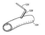
- FIG. 4Cillustrates an isometric view of the insertion of a anastomosis tool having an anvil into a target vessel, in accordance with one embodiment of the present invention.
- FIG. 4Dis an isometric view of the target vessel showing the stabilization of target vessel after the anvil is inserted into the target vessel.
- FIG. 4Eshows a side view of the spreader arm of FIG. 4A which more clearly shows grooves in the side of the spreader arm, in accordance with one embodiment of the present invention.
- FIG. 5illustrates a schematic top view of the graft vessel preparation device of FIG. 4A where the graft vessel is removed from the graft vessel preparation device, in accordance with one embodiment of the present invention.
- FIG. 6is a side view of the clamp of the graft vessel preparation device of FIG. 5 formed by a first clamp portion and a second clamp portion in accordance with one embodiment of the present invention.
- FIG. 7illustrates a side view of the clamp of FIG. 6 being inserted onto a anastomosis tool in accordance with one embodiment of the present invention.
- FIG. 8illustrates a method for slicing a graft vessel in preparation for a grafting procedure in accordance with one embodiment of the present invention.
- FIG. 9illustrates a perspective view of graft vessel preparation device in accordance with an embodiment of the present invention.
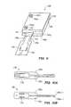
- FIG. 10Ashows a side view of a spreader of the graft vessel preparation device of FIG. 9, in accordance with one embodiment of the present invention.
- FIG. 10Billustrates a side view of the spreader of FIG. 10A, where the spreader is in a locked position in accordance with one embodiment of the present invention.
- FIG. 11shows a side view of the spreader of FIG. 10A, where graft vessel placed over the spreader in accordance with another embodiment of the present invention.
- FIG. 12shows a perspective view of a critical dimension locator of the graft vessel preparation device of FIG. 9, in accordance with one embodiment of the present invention.
- FIG. 13Ais an embodiment of the present invention where the spreader and graft vessel of FIG. 10B are engaged with the critical dimension locator of FIG. 12 .
- FIG. 13Bshows the spreader and the graft vessel of FIG. 13A rotated clockwise within the critical dimension locator of FIG. 13A in order to establish a critical dimension Y in accordance with one embodiment of the present invention.
- FIG. 14Ashows a perspective view of a second clamp half of the graft vessel preparation device of FIG. 9, in accordance with one embodiment of the present invention.
- FIG. 14Bshows a bottom view of the second clamp half of FIG. 14A, in accordance with one embodiment of the present invention.
- FIG. 15shows a top view of the slicing of the graft vessel of FIG. 13B with incisors in accordance with one embodiment of the present invention.
- FIG. 16illustrates the insertion of the graft vessel preparation device of FIG. 9 onto a anastomosis tool in accordance with one embodiment of the present invention.
- FIG. 17shows a method for preparing a graft vessel for an anastomosis procedure in accordance with one embodiment of the present invention.
- a graft vessel preparation device and a method for using the graft vessel preparation deviceis disclosed.
- the present inventionrelates to a graft vessel preparation device which prepares graft vessels for a vascular anastomosis procedure.
- the graft vesselis grafted to a target vessel, such as a coronary artery.
- a target vesselsuch as a coronary artery.
- the present inventionallows a surgeon to make precise incisions into a graft vessel prior to grafting the vessel to an artery.
- a surgeonmay make the incisions to create or define a critical dimension.
- the critical dimensionensures proper grafting of the graft vessel to the target vessel during the vascular anastomosis procedure. Proper grafting of the graft vessel to the target vessel is ensured since an incision having the critical dimension made in the graft vessel is equivalent to an incision having the critical dimension made in the target vessel.
- FIG. 1shows a graft vessel preparation device 100 having a graft vessel 112 inserted over spreader arms 108 a and 108 b in preparation for grafting.
- the graft vessel preparation device 100has a first base plate 102 a , a second base plate 102 b , the spreader arms 108 a and 108 b , and an extension link 104 .
- the graft vessel preparation device 100also includes a first clamp portion 110 a which is rotatably attached to the first base plate 102 a and the second base plate 102 b .
- the graft vessel 112may be a vessel taken from the body of a patient, such as from the leg of the patient, a synthetic graft, or other graft to be used to bypass an occlusion during a vascular anastomosis procedure. As will be described further with respect to FIGS. 4C and 4D, the graft vessel 112 is grafted to a target vessel 124 of the patient.
- the bases 102 a and 102 binclude the spreader arms 108 a and 108 b , the extension link 104 and the first clamp portion 110 a .
- the spreader arm 108 ais rigidly attached to the first base plate 102 a using any technique known in the art, including fasteners and machining such that the first base plate 102 a and the spreader arm 108 a form a single unit.
- the spreader arm 108 bis rigidly attached to the second base plate 102 b in the same manner as the spreader arm 108 a is attached to the first base plate 102 a .
- the extension link 104rotatably attaches the first base plate 102 a to the second base plate 102 b with fasteners 106 .
- the fasteners 106may be any suitable fastener which allows rotatable connection between the extension link 104 and both the first base plate 102 a and the second base plate 102 b .
- the first clamp portion 110 ais rotatably connected to both the first base plate 102 a and the second base plate 102 b in the same manner as the extension link 104 is attached to both the first base plate 102 a and the second base plate 102 b .
- the base plates 102 a and 102 b , the extension link 104 and the first clamp portion 110 atogether form a parallelogram linkage.
- the base plates 102 a and 102 bare linkages similar to the extension link 104 such that the linkages, along with the extension link 104 and the first clamp portion 110 a form a parallelogram linkage.
- the base 102 ais rigidly attached to a support base 107 .
- the extension link 104rotatably attaches the base 102 b to the base 102 a . Therefore, as will be further discussed with reference to FIG. 2, as the extension link 104 rotates, the base 102 b , which is not rigidly attached to the support base 107 , separates from the base 102 a.
- the angle X 1is the angle which both the first clamp portion 110 a and the extension link 104 form with respect to the X axis as shown with reference to FIG. 1 .
- the first clamp portion 110 a and the extension link 104are substantially parallel with one another such that the angle X 1 of the extension link 104 is substantially the same as the angle X 1 of the first clamp portion 110 a.
- the spreaders arms 108 a and 108 bare adjacent to one another such that they form a single unit.
- the spreader arms 108 a and 108 bare held adjacent to each other to form the single unit with a lock.
- the lockmay be any device suitable for holding the second-base plate 102 b such that the spreaders arms 108 a and 108 b form a single unit, such as a clamp or fasteners.
- a clamp 103is used to clamp the second base plate 102 b to form the single unit between the spreader arms 108 a and 108 b .
- the clamp 103includes a grommet 105 which is in contact with the second-base plate 102 b when the graft vessel preparation device 100 is in a locked position.
- the clamp 103releases the second base plate 102 b , the spreader arms 108 a and 108 b separate from one another, as shown with reference to FIG. 2 .
- FIG. 2is an embodiment of the present invention where the spreader arms 108 a and 108 b have been separated by a tension spring 114 .
- the tension spring 114is rigidly attached to the second base plate 102 b at one end and anchored (not shown) at the end opposite to the end rigidly attached to the second base plate 102 b .
- the tension spring 114is rigidly attached to the second base plate 102 b with any suitable technique known in the art, such as a fastener or a clip. Once the lock is disengaged, the tension spring 114 pulls on the second base plate 102 b in a downward direction, thereby separating the spreader arms 108 a and 108 b from each other.
- a force imparted by the tension spring 114 to separate the spreader arm 108 a from the spreader arm 108 bmay be selected such that the spreader arms exert a force within the graft vessel 112 in a range preferably between about 40 mm Hg and about 100 mm Hg, and more preferably about 60 mm Hg.
- the tension spring 114has a pretension of about 0.2 lbs., a rate between about 0.1 lb./in. to about 1 lb./in. and a length of about 1 inch.
- the extension link 104rotates to an angle X 2 with respect to the X axis to separate the first base plate 102 a from the second base plate 102 b .
- the spreader arms 108 a and 108 bseparate from one another since the spreader arms 108 a and 108 b are rigidly attached to the base plates 102 a and 102 b .
- the tensile spring 114continues to separate the spreader arms 108 a and 108 b from one another until the movement of the spreader arms 108 a and 108 b is limited by the fully extended the graft vessel 112 .
- a second clamp portion 110 bis attached to the first clamp portion 110 a , as shown with respect to FIG. 3 .
- FIG. 3shows the second clamp portion 110 b attached to the first clamp portion 110 a to trap the graft vessel 112 in a clamp 110 , in accordance with one embodiment of the present invention.
- the second clamp portion 110 battaches to the first clamp portion 110 a using fasteners 116 .
- the fasteners 116may be any suitable type of fastener which securely fastens the second clamp portion 110 b to the first clamp portion 110 a , such as a threaded fastener or the like.
- the clamp 110may have a single-piece hinged design where the clamp 110 a is rotatably attached with the clamp 110 b with any suitable technique, such as a hinge or the like.
- the angle X 2is maintained such that the second clamp portion 110 b is substantially aligned with the extension link 104 .
- the graft vessel 112is trapped by the clamp 110 .
- the graft vessel 112is ready for incision, or in an alternative embodiment, eversion. It should be noted that the trapped graft vessel 112 is sufficiently flattened by the clamp 110 to hold the graft vessel 112 in place without damaging the graft vessel 112 .
- FIG. 4Aillustrates incisors 118 a and 118 b slicing the graft vessel 112 , in accordance with one embodiment of the present invention.
- the incisors 118 a and 118 bmay be any type of device suitable for slicing a graft vessel, such as a scalpel, a knife, scissors, shears, or the like.
- the incisors 118 a and 118 bbegin slicing the graft vessel 112 at incision points 120 a and 120 b .
- the incision points 120 a and 120 bdefine a critical dimension Y, as shown more clearly with reference to FIG. 4 B.
- FIG. 4Bshows the critical dimension Y on the graft vessel 112 , in accordance with one embodiment of the present invention.
- the critical dimension Yis defined by the incision points 120 a and 120 b along the graft vessel 112 .
- the incision points 112 a and 112 bare defined as the points where the first clamp portion 110 a and the second clamp portion 110 b intersect with the graft vessel 112 .
- the defining and maintaining of critical dimension Y with the clamp 110allows for proper grafting of the graft vessel to a target vessel during the vascular anastomosis procedure: To further illustrate the anastomosis procedure, reference is now made to FIG. 4 C.
- FIG. 4Cillustrates the insertion of a anastomosis tool 126 having an anvil 128 into a target vessel 124 .
- an incisionmust be made in the target vessel 124 which allows the grafting of the graft vessel 112 to the target vessel 124 .
- the anvil 128 of the anastomosis toolis first inserted into the target vessel 124 . After the anvil 128 is inserted into the target vessel 124 the anvil is lifted in order to stabilize a wall of the target vessel 124 at the anastomosis site, as shown with reference to FIG. 4 D.
- FIG. 4Dillustrates the stabilization of the target vessel 124 after the anvil 128 is inserted into the target vessel 124 .
- a critical dimension Xis established along the target vessel 124 as shown with reference to FIG. 4 D.
- the critical dimension Xcorresponds substantially to the length of the anvil 128 along which the graft vessel 112 will be stapled, sutured or otherwise connected.
- the critical dimension Y established by the incision points 120 a and 120 bis equal or substantially equal to the critical dimension X formed by the anvil 128 .
- a length on an incision made in the target vessel 124is substantially the same as the critical dimension X.
- the incisionmay be made before or after the graft vessel 112 is connected to the target vessel 124 . Therefore, the formation of the critical dimension Y along the graft vessel 112 ensures that the graft vessel 112 will be properly grafted to the target vessel 124 during the grafting procedure.
- the graft vessel 112is sliced by the incisors 118 a and 118 b in a direction depicted by directional arrows B.
- the incisors 118 a and 118 bmay be guided by grooves 101 in the spreader arms 108 a and 108 b , as shown with reference to FIG. 4 E.
- the critical dimension Ymay also be maintained using other suitable techniques in addition to slicing the graft vessel, such as everting the graft vessel, or the like.
- the spreader arms 108 a and 108 bmay be removed from the graft vessel 112 and the graft vessel 112 may be sliced with scissors or a similar apparatus.
- the clamp 110maintains the critical dimension of the graft vessel 112 as the graft vessel 112 is sliced with scissors starting at the incision points 120 a and 120 b.
- FIG. 4Eshows the groove 101 in one of the spreader arms 108 a or 108 b , in accordance with one embodiment of the present invention.
- the groove 101guides the incisor 118 a as the incisor 118 a slices the graft vessel 112 .
- the groove 101also provides a hard surface for the incisor 118 a as the incisor 118 a slices the graft vessel 112 .
- the spreader arm 108 balso includes a groove (not shown) which guides the incisor 118 b as the incisor 118 b slices the graft vessel 112 .
- FIG. 5illustrates removing the graft vessel 112 from the graft vessel preparation device 100 , in accordance with one embodiment of the present invention.
- the clamp 110maintains the critical dimension Y of the graft vessel as the clamp 110 is attached to an automated anastomosis tool 132 , as will be described in greater-detail with respect to FIG. 7 . It should be noted that any device capable of holding the graft vessel 112 may be substituted for the clamp 110 .
- the clamp 110is configured to attach to the anastomosis tool 132 , as shown with reference to FIG. 6 .
- FIG. 6is a side view of the clamp 110 which is formed by the first clamp portion 110 a and the second clamp portion 110 b , in accordance with one embodiment of the present invention.
- the first clamp portion 110 a and the second clamp portion 110 bcontain alignment holes 130 a through 130 d .
- the alignment holes 130 a through 130 dalign the clamp 110 with the anastomosis tool 132 . It should be noted that other alignment features may be used to align the clamp 110 with the anastomosis tool 132 , such as a dovetail groove or the like. Also, the alignment holes 130 a through 130 d facilitate proper engagement of the clamp 110 with the anastomosis tool 132 , as shown with reference to FIG. 7 .
- FIG. 7illustrates the insertion of the clamp 110 onto the anastomosis tool 132 in accordance with one embodiment of the present invention.
- the anastomosis tool 132performs an anastomosis by connecting the graft vessel 112 to the target vessel 124 .
- An anastomosis toolwhich may be used is described in U.S. patent application Ser. No. 09/363,255, which is incorstudiod herein by reference in its entirety.
- the clamp 110 and the graft vessel 112must be attached to the anastomosis tool in order to complete the vascular anastomosis procedure.
- the clamp 110is transferred to the anastomosis tool 132 and attached to the anastomosis tool 132 via the alignment holes 130 a through 130 d .
- the alignment holes 130 a through 130 dfit over corresponding alignment pins 134 of the anastomosis tool 132 .
- the alignment pins 134ensure that the graft vessel 112 fits properly within the anastomosis tool 132 in order to allow proper grafting of the graft vessel 112 with the target vessel 124 .
- the alignment pins 134are rigidly attached to the anastomosis tool 132 by any suitable means, including pressing or molding the alignment pins 134 with the anastomosis tool 132 from a single material, such as acrylonitrite butadiene styrene (ABS) or polycarbonate; or threaded fasteners or the like.
- ABSacrylonitrite butadiene styrene
- polycarbonatepolycarbonate
- FIG. 8illustrates a method 200 for slicing a graft vessel in preparation for a vascular anastomosis procedure, in accordance with one embodiment of the present invention.
- a graft vessel preparation deviceis locked.
- spreader arms located on the graft vessel preparation deviceare adjacent to one another such that a single unit is formed.
- the graft vessel preparation device 100 shown with respect to FIG. 1is placed in a locked position such that the spreader arms 108 a and 108 b are adjacent to one another to form a single unit.
- the clamp 103clamps down onto the second base plate 102 b to lock the graft vessel preparation device 100 .
- the clamp 103clamps the second base plate 102 b
- the spreader arms 108 a and 108 bare held adjacent to each other to form a single unit.
- an operation 204is performed.
- a graft vesselis placed over the spreader arms of the graft vessel preparation device.
- the graft vesselis placed over the spreader arms such that the spreader arms occupy an interior of the graft vessel.
- the graft vessel 112is placed over the spreader arms 108 a and 108 b after the graft vessel preparation device 100 is locked.
- the graft vessel 112is placed over the spreader arms 108 a and 108 b such that the spreader arms 108 a and 108 b occupy an interior of the graft vessel 112 , as shown with respect to FIG. 1 .
- an operation 206is performed.
- the spreader armsseparate within an interior of the graft vessel.
- the spreader armsseparate within the interior of the graft vessel until the spreader arms stretch the graft vessel.
- the graft vesselis stretched until a distance between the spreader arms is half the circumference of the graft vessel, such that the graft vessel is stretched flat.
- the spreader armsexert a force on the graft vessel which is equivalent to or less than the force exerted by the blood pressure of blood that normally flows through the graft vessel.
- the spreader armsmay be pushed further into the graft vessel to fully support the end of the graft vessel.
- the spreader armsmay be locked to maintain the proper stretched configuration.
- the spreader arms 108 a and 108 bseparate within the interior of the graft vessel 112 . As described earlier, the spreader arms 108 a and 108 b separate due to the force applied by the tension spring 114 .
- the tension spring 114continues to separate the spreader arms 108 a and 108 b within the graft vessel 112 until the spreader arms 108 a and 108 b are in contact with interior walls of the graft vessel 112 . Once the spreader arms 108 a and 108 b fully separate within the interior of the graft vessel 112 and apply the desired force, the method performs an operation 208 .
- the graft vesselis secured with a clamp.
- incision points on the graft vesselare defined where the graft vessel and the clamp intersect with one another.
- the incision pointsdefine a critical dimension of the graft vessel and where the graft vessel will be'sliced, as will be discussed further with reference to operation 210 .
- the graft vessel preparation device 100includes the first clamp portion 110 a as previously described.
- the graft vessel 112was placed over the spreader arms 108 a and 108 b in the operation 204 , the graft vessel 112 was laid over the first clamp portion 110 a .
- the second clamp portion 110 bis attached to the first clamp portion 110 a (shown with reference to FIG. 1) with the fasteners 116 to form the clamp 110 .
- the intersection of the clamp 110 and the graft vessel 112define the incision points 120 a and 120 b where the graft vessel is to be sliced in the operation 210 .
- the spreader armsPrior to slicing the graft vessel in the operation 210 , the spreader arms are mounted further within the interior of the graft vessel. The spreader arms are pushed further within the graft vessel in order to assist the incisors in the slicing operation.
- the spreader armscontain grooves which provide a surface for the incisors as the incisors slice graft vessel. Moreover, the groove provides a track which facilitates the slicing of the graft vessel during the slicing operation described with respect to the operation 210 .
- the graft vesselis sliced after the graft vessel is secured with the clamp in the operation 208 .
- the incisors 118 a and 118 bslice the graft vessel 112 from the incision points 120 a and 120 b outward to an end of the graft vessel 112 .
- the incision made in the graft vessel 112is made such that the graft vessel 112 may be properly grafted to the target vessel 124 during the vascular anastomosis procedure.
- the graft vessel 112 and the clamp 110are removed from the graft vessel preparation device 100 by disengaging the clamp 110 from the graft preparation device 100 and sliding the graft vessel 112 off of the spreader arms 108 a and 108 b . After the operation 212 is complete, the graft vessel 212 is ready for grafting to a target vessel during the vascular anastomosis procedure.
- FIG. 9illustrates a graft vessel preparation device or flapper 148 in accordance with an alternative embodiment of the present invention.
- the graft vessel flapperincludes a locator clamp 150 having alignment holes 146 and a spreader 136 .
- the alignment holes 146align the locator clamp 150 with the anastomosis tool 132 .
- the alignment holes 146facilitate proper engagement of the graft vessel flapper 148 with the anastomosis tool 132 , as will be further discussed with reference to FIG. 16 .
- the locator clamp 150establishes the critical dimension Y (not shown) of the graft vessel 112 , as will be further discussed with reference to FIGS. 12 through 14B.
- the spreader 136includes a first spreader arm 136 a and a second spreader arm 136 b , as more clearly shown with reference to FIG. 10 A.
- FIG. 10Ashows the spreader 136 , in accordance with one embodiment of the present invention.
- the spreader 136includes the first spreader arm 136 a and the second spreader arm 136 b which are movable with respect to one another.
- the spreader arms 136 a and 136 bare moved with respect to one another by a spring 138 .
- the spring 138is a torsion spring in one embodiment of the present invention which connects the first spreader arm 136 a to the second spreader arm 136 b .
- the spring 138attaches to a distal end of the first spreader arm 136 a and a distal end of the second spreader arm 136 b .
- the spring 138may be any suitable type of spring which separates the first spreader arm 136 a from the second spreader arm 136 b , such as a torsion spring, a leaf spring, a compression spring, an elastomer having spring-like characteristics, or the like. In one embodiment of the present invention.
- the spring 138is a torsion spring having a spring rate in preferably in a range between about 0.001 lbs./deg. to about 0.01 lbs./deg. and more preferably about 0.00156 lbs./deg.
- the first spreader arm 136 a and the second spreader arm 136 bare configured to receive the graft vessel 112 when the spreader 136 is in a locked position, as shown with reference to FIG. 10 B.
- FIG. 10Billustrates the spreader 136 in a locked or closed position, in accordance with another embodiment of the present invention.
- the spreader 136is locked when an end 136 a - 1 of. the first spreader arm 136 a makes contact or is positioned substantially adjacent to an end 136 b - 1 of the second spreader arm 136 b , as shown with reference to FIG. 10 B.
- the spreader 136is placed into the locked position using any suitable technique, such as a clip, a clamp or the like.
- the spreader arms 136 a and 136 bare placed in the locked position, the spreader 136 receives the graft vessel 112 , as shown with reference to FIG. 11 .
- FIG. 11shows the graft vessel 112 placed over the spreader 136 , in accordance with one embodiment of the present invention.
- the first spreader arm 136 a and the second spreader arm 136 bseparate within an interior of the graft vessel 112 .
- the spreader arms 136 a and 136 bseparate by the action of the spring 138 .
- the first spreader arm 136 a and the second spreader arm 136 bseparate until the first spreader arm 136 a and the second spreader arm 136 b are adjacent interior walls of the graft vessel 112 and stretch the graft vessel 112 a desired amount which simulates the condition of the graft vessel when implanted in the body.
- the graft vessel flapper 148 shown with respect to FIG. 9also includes the locator clamp 150 .
- the locator clamp 150includes a critical dimension locator 140 , as more clearly shown with reference to FIG. 12 .
- the critical dimension locator 140has a raised portion 140 a , a base 140 b and threaded fasteners 140 c .
- the raised portion 140 ais rigidly attached to the base 140 b and may be formed into the base 140 b using any suitable techniques, such as spot welding, injection molding, or the like. In the embodiment shown with respect to FIG. 12, the raised portion 140 a is in a triangular configuration.
- the raised portion 140 amay have any orientation which allows for the establishment of a critical dimension Y for the graft vessel 112 , as will be more fully discussed with reference to FIG. 13 A. It should also be noted that in an alternative embodiment of the present invention, the raised portion 140 a is not rigidly attached to the critical dimension locator 140 . Thus, as will be more fully discussed with reference to FIG. 13A, once a graft vessel is placed on the critical dimension locator 140 , the raised portion 140 a may also be coupled with the critical dimension locator 140 .
- the threaded fastener 140 callows connection between the critical dimension locator 140 and a second clamp half 142 (not shown).
- the threaded fastener 140 cmay be any type of fastener suitable for connecting the critical dimension locator 140 with the second clamp half 142 . Also, the threaded fastener 140 c has an edge 140 c - 1 and the raised portion 140 a includes an edge 140 a - 1 . The raised portion 140 a , along width the threaded fastener 140 c , establishes a critical dimension Y for the graft vessel 112 defined between the edges 140 a - 1 and 140 c - 1 , as shown with reference to FIGS. 13A and 13B.
- FIG. 13Ais an embodiment of the present invention showing the spreader 136 , along with the graft 112 , engaged with the critical dimension locator 140 .
- the spreader 136is placed on to the critical dimension locator 140 in order to establish the critical dimension Y.
- the spreader 136 and the graft vessel 112are placed in the critical dimension locator 140 such that the graft vessel 112 resides between the edges 140 a - 1 and 140 c - 1 .
- the spreader 136 and the graft vessel 112are placed within the critical dimension locator 140 , the spreader 136 and the graft vessel 112 are rotated in a clockwise direction Z on the critical dimension locator 140 , as shown with respect to FIG. 13 B.
- FIG. 13Bshows the spreader 136 , along with the graft vessel 112 , rotated clockwise within the critical dimension locator 140 in order to establish the critical dimension Y, in accordance with one embodiment of the present invention.
- the spreader 136 and the graft vessel 112are rotated until the graft vessel 112 comes into contact with the edges 140 a - 1 and 140 c - 1 at contact points 120 a and 120 b , as shown with reference to FIG. 13 B.
- the contact points 120 a and 120 bare the endpoints for the critical dimension Y.
- the critical dimension Yallows for proper grafting of the graft vessel to a target vessel during a vascular anastomosis procedure.
- the second clamp half 142is more clearly shown with reference to FIG. 14 A.
- the second half clamp 142includes through holes 142 a and a recess 142 b .
- the through holes 142 aallow for passage of the threaded fasteners 140 c of the critical dimension locator 140 through the second half clamp 142 such that the second clamp half 142 may attach to the critical dimension locator 140 .
- the recess 142 ballows the raised portion 140 a to fit within the second half clamp 142 when the second clamp half 142 is attached to the critical dimension locator 140 , as shown with reference to FIG. 9 .
- the recess 142 bhas a triangular configuration as shown with respect to FIG. 14B such that the critical dimension locator 140 will fit flush with the second half clamp 142 . It should be noted that the configuration of the recess 142 b complements the configuration of the raised portion 140 a . Thus, if in an alternative embodiment of the present invention, the raised portion 140 a contains a square configuration, the recess 142 b will also have a square configuration.
- the second clamp half 142is securely attached to the critical dimension locator 140 to form the locator clamp 150 .
- the second clamp half 142is securely attached to the critical dimension locator 140 by passing the threaded fasteners 140 a through the through holes 142 a of the second clamp half 142 .
- a fastener 140 dis then fixed to the threaded fasteners 140 c .
- the fastener 140 dmay be any suitable type of fastener which securely attaches the second clamp half 142 to the critical dimension locator 140 , such as a threaded nut or the like.
- FIG. 15shows the graft vessel 112 being sliced with the incisors 118 a and 118 b , in accordance with one embodiment of the present invention.
- the incisors 118 a and 118 bslice the graft vessel 112 from the incision points 120 a and 120 b outward to an end of the graft vessel 112 in order to maintain the critical dimension Y.
- the incisors 118 a and 118 bmay slice the graft vessel 112 at any point, as long as the critical dimension Y is maintained.
- the incisors 118 a and 118 bmay slice the graft vessel 112 at the points 121 a and 121 b , which, as may be seen with reference to FIG. 15, maintain the critical dimension Y.
- the incisors 118 a and 118 bmay be any type of cutting device suitable for slicing graft vessels, such as a scalpel, a pair of scissors or the like.
- FIG. 16illustrates the insertion of the graft vessel flapper 148 onto the anastomosis tool 132 , in accordance with one embodiment of the present invention.
- the anastomosis tool 132grafts the graft vessel 112 to the target vessel 124 during the vascular anastomosis procedure.
- the vascular anastomosis procedureis performed using the anastomosis tool 132 .
- the graft vessel flapper 148 and the graft vessel 112must be attached to the anastomosis tool 132 in order to complete the vascular anastomosis procedure.
- the graft vessel flapper 148is attached to the anastomosis tool 132 via the alignment holes 146 .
- the alignment holes 146fit over the alignment pins 134 in order to ensure proper fitment of the graft vessel flapper 148 with the anastomosis tool 132 .
- proper fitting of the graft vessel flapper 148 with the anastomosis tool 132is necessary for proper grafting of the graft vessel 112 to the target vessel 124 during the vascular anastomosis procedure.
- FIG. 17shows the method 300 for preparing a graft vessel for an anastomosis procedure in accordance with one embodiment of the present invention.
- an operation 302is first performed where a spreader is locked.
- the spreaderis locked in order to allow the placement of a graft vessel over the spreader.
- the spreader 136is placed in a locked position.
- the spreader 136may be locked using any suitable technique, including a clamp, a clip, or simply pinching closed the spreader with a user's fingers such that spreader arms of the spreader are held together. As may be seen with respect to FIG.
- the spreader 136is locked such that the first spreader arm 136 a contacts the second spreader arm 136 b at the ends 136 a - 1 and 136 b - 1 .
- the spreader 136is configured to receive a graft vessel, as described with respect to an operation 304 .
- the operation 304 in FIG. 17is performed once the spreader is locked.
- a graft vesselis placed over the spreader while the spreader is in the locked position.
- the spreader arms of the spreaderare separated within an interior of the graft vessel in the operation 306 .
- the first spreader arm 136 a and the second spreader arm 136 bseparate from each other within the interior of the graft vessel 112 .
- the spring 138separates the first spreader arm 136 a from the second spreader arm 136 b .
- the first spreader arm 136 a and the second spreader arm 136 bcontinue to separate from one another until both the spreader arms 136 a and 136 b come into contact with an interior surface of the graft vessel 112 . Once the first spreader arm 136 a and the second spreader arm 136 b separate within the graft vessel 112 in the operation 306 , an operation 308 is performed.
- the spreaderalong with the graft vessel, is placed onto a graft vessel flapper.
- the graft vessel flapperestablishes a critical dimension on the graft vessel.
- the critical dimension locator 140forms part of the graft vessel flapper 148 .
- the spreader 136 and the graft vessel 112are placed in the critical dimension locator 140 .
- an operation 310is performed.
- the spreader and the graft vesselare rotated within the graft vessel flapper.
- the spreaderis rotated until the graft vessel comes into contact with edges of the graft vessel flapper.
- the edges of the graft vessel flapperestablish the endpoints of the critical dimension when the graft vessel contacts the edges, thereby establishing the critical dimension on the graft vessel.
- the spreader 136 and the graft vessel 112are rotated in the clockwise direction Z until the graft vessel 112 comes into contact with the edges 140 a - 1 and 140 c - 1 of the critical dimension locator 140 , as shown with reference to FIG. 13 B.
- the graft vessel 112contacts the edges 140 a - 1 and 140 c - 1 at the endpoints 120 a and 120 b . As previously described, the endpoints 120 a and 120 b establish the critical dimension Y. Once the critical dimension Y is established in the operation 310 , the graft vessel 112 is trapped in operation 311 .
- the graft vessel 112is trapped in the operation 311 as a second clamp half is attached to graft vessel flapper.
- the second half clampis attached to the graft vessel flapper, the graft vessel flapper holds the critical dimension Y.
- the second clamp half 142is attached to the graft vessel flapper 148 .
- the second clamp half 142is attached to the graft vessel flapper 148 when the threaded fasteners 140 c pass through the through holes 142 a and secured with the fasteners 140 d .
- the graft vessel 112is sliced in an operation 312 .
- the graft vessel flapperis attached to a anastomosis tool in the operation 314 .
- the anastomosis toolfacilitates grafting of the graft vessel to a target vessel during a vascular anastomosis procedure.
- the graft vessel 112is first sliced in the operation 312 and then attached to the anastomosis tool 132 .
- the graft vessel flapper 148attaches to the anastomosis tool 132 via the alignment holes 146 and alignment pins 134 .
- the graft vessel 112is grafted to the target vessel 124 during the vascular anastomosis procedure.
- This graftingmay be performed by any method suitable for grafting a graft vessel to a target vessel, such as suturing, stapling, tissue welding, clamping or the like.
- the present inventionnow offers surgeons an automated method for accurately grafting a graft vessel to a target vessel.
- the prior art problems of dealing with the innate flexing tendencies of the graft vessel due to the small size and the flexible, circular configuration of the of the graft vesselare obviated with the present invention.
- the graft vessel preparation deviceaccurately and precisely allows the graft vessel to be a cut in a manner which allows a perimeter of the graft vessel end to be matched to a perimeter of an anastomosis site on a target vessel.
- the surgeonsaves the time required to accurately and precisely slice the graft vessel, thereby decreasing the overall time a patient spends in surgery and decreasing the overall costs associated with spending time in surgery.
- an assistantmay be required to hold the edges of the graft vessel and assist in preparing the graft vessel for the anastomosis procedure.
- the clamp of the present inventionholds the graft vessel as the graft vessel is placed in the anastomosis tool.
- the clamp of the present inventionalso holds the graft vessel during the anastomosis procedure.
Landscapes
- Health & Medical Sciences (AREA)
- Engineering & Computer Science (AREA)
- Biomedical Technology (AREA)
- Gastroenterology & Hepatology (AREA)
- Pulmonology (AREA)
- Cardiology (AREA)
- Oral & Maxillofacial Surgery (AREA)
- Transplantation (AREA)
- Heart & Thoracic Surgery (AREA)
- Vascular Medicine (AREA)
- Life Sciences & Earth Sciences (AREA)
- Animal Behavior & Ethology (AREA)
- General Health & Medical Sciences (AREA)
- Public Health (AREA)
- Veterinary Medicine (AREA)
- Surgical Instruments (AREA)
Abstract
Description
Claims (17)
Priority Applications (2)
| Application Number | Priority Date | Filing Date | Title |
|---|---|---|---|
| US10/367,175US6786862B2 (en) | 2000-11-13 | 2003-02-14 | Graft vessel preparation device and methods for using the same |
| US10/871,823US20040236178A1 (en) | 2003-02-14 | 2004-06-18 | Method for preparing a graft vessel for anastomosis |
Applications Claiming Priority (2)
| Application Number | Priority Date | Filing Date | Title |
|---|---|---|---|
| US09/712,044US6554764B1 (en) | 2000-11-13 | 2000-11-13 | Graft vessel preparation device and methods for using the same |
| US10/367,175US6786862B2 (en) | 2000-11-13 | 2003-02-14 | Graft vessel preparation device and methods for using the same |
Related Parent Applications (1)
| Application Number | Title | Priority Date | Filing Date |
|---|---|---|---|
| US09/712,044ContinuationUS6554764B1 (en) | 2000-11-13 | 2000-11-13 | Graft vessel preparation device and methods for using the same |
Related Child Applications (1)
| Application Number | Title | Priority Date | Filing Date |
|---|---|---|---|
| US10/871,823ContinuationUS20040236178A1 (en) | 2003-02-14 | 2004-06-18 | Method for preparing a graft vessel for anastomosis |
Publications (2)
| Publication Number | Publication Date |
|---|---|
| US20030163023A1 US20030163023A1 (en) | 2003-08-28 |
| US6786862B2true US6786862B2 (en) | 2004-09-07 |
Family
ID=24860573
Family Applications (2)
| Application Number | Title | Priority Date | Filing Date |
|---|---|---|---|
| US09/712,044Expired - Fee RelatedUS6554764B1 (en) | 2000-11-13 | 2000-11-13 | Graft vessel preparation device and methods for using the same |
| US10/367,175Expired - Fee RelatedUS6786862B2 (en) | 2000-11-13 | 2003-02-14 | Graft vessel preparation device and methods for using the same |
Family Applications Before (1)
| Application Number | Title | Priority Date | Filing Date |
|---|---|---|---|
| US09/712,044Expired - Fee RelatedUS6554764B1 (en) | 2000-11-13 | 2000-11-13 | Graft vessel preparation device and methods for using the same |
Country Status (1)
| Country | Link |
|---|---|
| US (2) | US6554764B1 (en) |
Cited By (2)
| Publication number | Priority date | Publication date | Assignee | Title |
|---|---|---|---|---|
| US20040236178A1 (en)* | 2003-02-14 | 2004-11-25 | Cardica, Inc. | Method for preparing a graft vessel for anastomosis |
| US9955969B2 (en) | 2005-05-26 | 2018-05-01 | Texas Heart Institute | Surgical system and method for attaching a prosthetic vessel to a hollow structure |
Families Citing this family (12)
| Publication number | Priority date | Publication date | Assignee | Title |
|---|---|---|---|---|
| US6554764B1 (en)* | 2000-11-13 | 2003-04-29 | Cardica, Inc. | Graft vessel preparation device and methods for using the same |
| US7331972B1 (en) | 2002-11-15 | 2008-02-19 | Abbott Cardiovascular Systems Inc. | Heart valve chord cutter |
| US20050149071A1 (en)* | 2003-12-24 | 2005-07-07 | Ryan Abbott | Anastomosis device, tools and method of using |
| US20080269784A1 (en)* | 2003-12-24 | 2008-10-30 | Ryan Abbott | Anastomosis device, tools and methods of using |
| US7585306B2 (en)* | 2003-12-24 | 2009-09-08 | Maquet Cardiovascular Llc | Anastomosis device, tools and methods of using |
| US8162963B2 (en)* | 2004-06-17 | 2012-04-24 | Maquet Cardiovascular Llc | Angled anastomosis device, tools and method of using |
| EP2173259A4 (en) | 2007-08-02 | 2015-07-08 | Bio Connect Systems | Implantable flow connector |
| US20130197546A1 (en) | 2007-08-02 | 2013-08-01 | Bioconnect Systems, Inc. | Implantable flow connector |
| US9463015B2 (en) | 2011-09-09 | 2016-10-11 | Cardica, Inc. | Surgical stapler for aortic anastomosis |
| US9314600B2 (en) | 2012-04-15 | 2016-04-19 | Bioconnect Systems, Inc. | Delivery system for implantable flow connector |
| US10434293B2 (en) | 2012-04-15 | 2019-10-08 | Tva Medical, Inc. | Implantable flow connector |
| US11540816B2 (en) | 2020-03-17 | 2023-01-03 | Bruce Mindich | System for preparing a harvested blood vessel for grafting |
Citations (96)
| Publication number | Priority date | Publication date | Assignee | Title |
|---|---|---|---|---|
| US3254650A (en) | 1962-03-19 | 1966-06-07 | Michael B Collito | Surgical anastomosis methods and devices |
| US3519187A (en) | 1966-12-06 | 1970-07-07 | Nickolai Nickolajevich Kapitan | Instrument for suturing vessels |
| US3774615A (en) | 1971-02-08 | 1973-11-27 | Ceskoslovenska Akademie Ved | Device for connecting or joining the ends of interrupted tubular organs in surgical operations without stitching |
| US3916874A (en) | 1974-03-11 | 1975-11-04 | Richard Perrin | Intraluminal vein holder |
| US4214587A (en) | 1979-02-12 | 1980-07-29 | Sakura Chester Y Jr | Anastomosis device and method |
| US4232659A (en) | 1979-01-08 | 1980-11-11 | Codman And Shurtleff, Inc. | Vein holder assembly |
| US4350160A (en) | 1979-11-14 | 1982-09-21 | Kolesov Evgeny V | Instrument for establishing vascular anastomoses |
| US4352358A (en) | 1979-12-28 | 1982-10-05 | Angelchik Jean P | Apparatus for effecting anastomotic procedures |
| US4366819A (en) | 1980-11-17 | 1983-01-04 | Kaster Robert L | Anastomotic fitting |
| US4368736A (en) | 1980-11-17 | 1983-01-18 | Kaster Robert L | Anastomotic fitting |
| US4503568A (en) | 1981-11-25 | 1985-03-12 | New England Deaconess Hospital | Small diameter vascular bypass and method |
| US4523592A (en) | 1983-04-25 | 1985-06-18 | Rollin K. Daniel P.S.C. | Anastomotic coupling means capable of end-to-end and end-to-side anastomosis |
| US4553542A (en) | 1982-02-18 | 1985-11-19 | Schenck Robert R | Methods and apparatus for joining anatomical structures |
| US4589416A (en) | 1983-10-04 | 1986-05-20 | United States Surgical Corporation | Surgical fastener retainer member assembly |
| US4593693A (en) | 1985-04-26 | 1986-06-10 | Schenck Robert R | Methods and apparatus for anastomosing living vessels |
| US4607637A (en) | 1983-07-22 | 1986-08-26 | Anders Berggren | Surgical instrument for performing anastomosis with the aid of ring-like fastening elements and the fastening elements for performing anastomosis |
| US4624255A (en) | 1982-02-18 | 1986-11-25 | Schenck Robert R | Apparatus for anastomosing living vessels |
| US4624257A (en) | 1982-06-24 | 1986-11-25 | Anders Berggren | Surgical instrument for performing anastomosis |
| US4657019A (en) | 1984-04-10 | 1987-04-14 | Idea Research Investment Fund, Inc. | Anastomosis devices and kits |
| US4665906A (en) | 1983-10-14 | 1987-05-19 | Raychem Corporation | Medical devices incorporating sim alloy elements |
| US4747407A (en) | 1985-09-03 | 1988-05-31 | The Field Surgery Research Department of the Third Military Medical University | Blood vessel anastomat |
| US4856518A (en) | 1987-12-09 | 1989-08-15 | Mcfadden Joseph T | Articulable, rotatable, surgical clamping device |
| US4907591A (en) | 1988-03-29 | 1990-03-13 | Pfizer Hospital Products Group, Inc. | Surgical instrument for establishing compression anastomosis |
| US4917087A (en) | 1984-04-10 | 1990-04-17 | Walsh Manufacturing (Mississuaga) Limited | Anastomosis devices, kits and method |
| US4917091A (en) | 1982-06-24 | 1990-04-17 | Unilink Ab | Annular fastening means |
| US5007920A (en) | 1989-03-24 | 1991-04-16 | Torre Randall J | Tendon sectioning support clamp |
| US5062842A (en) | 1989-12-21 | 1991-11-05 | Coherent, Inc. | Isotopic co2 laser and method of use for medical treatment |
| WO1992008513A1 (en) | 1990-11-20 | 1992-05-29 | Interventional Thermodynamics, Inc. | Tension guide and dilator |
| US5119983A (en) | 1987-05-26 | 1992-06-09 | United States Surgical Corporation | Surgical stapler apparatus |
| US5133724A (en)* | 1991-04-04 | 1992-07-28 | Pilling Co. | Abdominal aortic clamp |
| EP0517252A1 (en) | 1991-06-06 | 1992-12-09 | Blake, Joseph Walter III | Disposable vascular punch |
| US5171262A (en) | 1989-06-15 | 1992-12-15 | Cordis Corporation | Non-woven endoprosthesis |
| US5217474A (en) | 1991-07-15 | 1993-06-08 | Zacca Nadim M | Expandable tip atherectomy method and apparatus |
| US5234447A (en) | 1990-08-28 | 1993-08-10 | Robert L. Kaster | Side-to-end vascular anastomotic staple apparatus |
| US5250060A (en) | 1992-06-26 | 1993-10-05 | Carbo Paul L | Angioplasty apparatus |
| US5298012A (en) | 1991-09-30 | 1994-03-29 | Baxter International Inc. | Tendon graft preparation workstation |
| US5304220A (en) | 1991-07-03 | 1994-04-19 | Maginot Thomas J | Method and apparatus for implanting a graft prosthesis in the body of a patient |
| US5314468A (en) | 1989-03-31 | 1994-05-24 | Wilson Ramos Martinez | Aortic valved tubes for human implants |
| US5336233A (en) | 1989-01-26 | 1994-08-09 | Chen Fusen H | Anastomotic device |
| US5354302A (en) | 1992-11-06 | 1994-10-11 | Ko Sung Tao | Medical device and method for facilitating intra-tissue visual observation and manipulation of distensible tissues |
| US5366462A (en) | 1990-08-28 | 1994-11-22 | Robert L. Kaster | Method of side-to-end vascular anastomotic stapling |
| US5395311A (en) | 1990-05-14 | 1995-03-07 | Andrews; Winston A. | Atherectomy catheter |
| US5443497A (en) | 1993-11-22 | 1995-08-22 | The Johns Hopkins University | Percutaneous prosthetic by-pass graft and method of use |
| US5447515A (en)* | 1994-02-08 | 1995-09-05 | Pilling Co. | Coronary bypass clamp |
| US5456714A (en) | 1991-07-04 | 1995-10-10 | Owen; Earl R. | Tubular surgical implant having a locking ring and flange |
| US5464449A (en) | 1993-07-08 | 1995-11-07 | Thomas J. Fogarty | Internal graft prosthesis and delivery system |
| US5472404A (en) | 1995-02-21 | 1995-12-05 | Volgushev; Valentin E. | Method for surgical correction of vascular occlusions |
| US5478354A (en) | 1993-07-14 | 1995-12-26 | United States Surgical Corporation | Wound closing apparatus and method |
| US5522834A (en) | 1992-10-15 | 1996-06-04 | Applied Medical Resources Corporation | Internal mammary artery catheter and method |
| US5556405A (en) | 1995-10-13 | 1996-09-17 | Interventional Technologies Inc. | Universal dilator with reciprocal incisor |
| US5558667A (en) | 1994-12-14 | 1996-09-24 | Coherent, Inc. | Method and apparatus for treating vascular lesions |
| US5562241A (en) | 1994-02-03 | 1996-10-08 | Ethicon Endo-Surgery, Inc. | Surgical stapler instrument |
| US5630831A (en) | 1995-05-04 | 1997-05-20 | Lahr; Christopher J. | Fingerlike medical instruments for use in laparoscopic procedures |
| US5643340A (en) | 1994-10-27 | 1997-07-01 | Nunokawa; Mioko | Synthetic vascular prosthesis |
| WO1997025002A1 (en) | 1996-01-05 | 1997-07-17 | Medtronic, Inc. | Expansible endoluminal prostheses |
| WO1997027898A1 (en) | 1996-02-02 | 1997-08-07 | Transvascular, Inc. | Methods and apparatus for connecting openings formed in adjacent blood vessels or other anatomical structures |
| WO1997031575A1 (en) | 1996-02-29 | 1997-09-04 | Oticon A/S | Method and anastomotic instrument for use when performing an end-to-side anastomosis |
| US5669918A (en) | 1995-03-16 | 1997-09-23 | Deutsche Forschungsanstalt Fur Luft-Und Raumfahrt E.V. | Surgical instrument for preparing an anastomosis in minimally invasive surgery |
| US5676670A (en) | 1996-06-14 | 1997-10-14 | Beth Israel Deaconess Medical Center | Catheter apparatus and method for creating a vascular bypass in-vivo |
| US5693088A (en) | 1993-11-08 | 1997-12-02 | Lazarus; Harrison M. | Intraluminal vascular graft |
| US5695504A (en) | 1995-02-24 | 1997-12-09 | Heartport, Inc. | Devices and methods for performing a vascular anastomosis |
| US5702412A (en) | 1995-10-03 | 1997-12-30 | Cedars-Sinai Medical Center | Method and devices for performing vascular anastomosis |
| US5707380A (en) | 1996-07-23 | 1998-01-13 | United States Surgical Corporation | Anastomosis instrument and method |
| US5707362A (en) | 1992-04-15 | 1998-01-13 | Yoon; Inbae | Penetrating instrument having an expandable anchoring portion for triggering protrusion of a safety member and/or retraction of a penetrating member |
| US5709693A (en) | 1996-02-20 | 1998-01-20 | Cardiothoracic System, Inc. | Stitcher |
| US5709335A (en) | 1994-06-17 | 1998-01-20 | Heartport, Inc. | Surgical stapling instrument and method thereof |
| WO1998007399A1 (en) | 1996-08-23 | 1998-02-26 | Beth Israel Deaconess Medical Center | CATHETER APPARATUS AND METHOD USING A SHAPE-MEMORY ALLOY CUFF FOR CREATING A BYPASS GRAFT $i(IN VIVO) |
| US5725553A (en) | 1996-02-29 | 1998-03-10 | Moenning; Stephen P. | Apparatus and method for protecting a port site opening in the wall of a body cavity |
| US5725544A (en) | 1993-12-23 | 1998-03-10 | Oticon A/S | Method and instrument for establishing the receiving site of a coronary artery bypass graft |
| US5732872A (en) | 1994-06-17 | 1998-03-31 | Heartport, Inc. | Surgical stapling instrument |
| WO1998019631A1 (en) | 1996-11-07 | 1998-05-14 | Vascular Science Inc. | Artificial medical graft methods and apparatus |
| WO1998019632A1 (en) | 1996-11-07 | 1998-05-14 | Vascular Science Inc. | Artificial tubular body organ grafts |
| WO1998019630A2 (en) | 1996-11-07 | 1998-05-14 | Vascular Science Inc. | Tubular medical graft connectors |
| WO1998019634A2 (en) | 1996-11-07 | 1998-05-14 | Vascular Science Inc. | Medical grafting methods and apparatus |
| WO1998019618A1 (en) | 1996-11-07 | 1998-05-14 | Vascular Science Inc. | Tubular body structure marking methods and apparatus |
| WO1998019629A2 (en) | 1996-11-07 | 1998-05-14 | Vascular Science Inc. | Medical grafting connectors and fasteners |
| WO1998019625A2 (en) | 1996-11-08 | 1998-05-14 | Houser Russell A | Percutaneous bypass graft and securing system |
| US5810880A (en) | 1995-06-07 | 1998-09-22 | Sri International | System and method for releasably holding a surgical instrument |
| US5881943A (en) | 1994-06-17 | 1999-03-16 | Heartport, Inc. | Surgical anastomosis apparatus and method thereof |
| US5893369A (en) | 1997-02-24 | 1999-04-13 | Lemole; Gerald M. | Procedure for bypassing an occlusion in a blood vessel |
| US5902228A (en) | 1996-10-11 | 1999-05-11 | Cornell Research Foundation, Inc. | Method and apparatus for support and tubularization of surgical grafts |
| US5904697A (en) | 1995-02-24 | 1999-05-18 | Heartport, Inc. | Devices and methods for performing a vascular anastomosis |
| US5921995A (en) | 1996-10-16 | 1999-07-13 | Nitinol Medical Technologies, Inc. | Anastomosis Device |
| US5944730A (en) | 1997-05-19 | 1999-08-31 | Cardio Medical Solutions, Inc. | Device and method for assisting end-to-side anastomosis |
| US5976159A (en) | 1995-02-24 | 1999-11-02 | Heartport, Inc. | Surgical clips and methods for tissue approximation |
| US6007544A (en) | 1996-06-14 | 1999-12-28 | Beth Israel Deaconess Medical Center | Catheter apparatus having an improved shape-memory alloy cuff and inflatable on-demand balloon for creating a bypass graft in-vivo |
| US6022367A (en) | 1997-06-18 | 2000-02-08 | United States Surgical | Surgical apparatus for forming a hole in a blood vessel |
| US6113612A (en) | 1998-11-06 | 2000-09-05 | St. Jude Medical Cardiovascular Group, Inc. | Medical anastomosis apparatus |
| US6132472A (en) | 1991-08-12 | 2000-10-17 | Bonutti; Peter M. | Tissue press and system |
| US6152937A (en) | 1998-11-06 | 2000-11-28 | St. Jude Medical Cardiovascular Group, Inc. | Medical graft connector and methods of making and installing same |
| US6165185A (en) | 1999-07-28 | 2000-12-26 | Vasconnect, Inc. | Method for interconnecting vessels in a patient |
| US6368332B1 (en) | 1999-03-08 | 2002-04-09 | Septimiu Edmund Salcudean | Motion tracking platform for relative motion cancellation for surgery |
| US6391038B2 (en)* | 1999-07-28 | 2002-05-21 | Cardica, Inc. | Anastomosis system and method for controlling a tissue site |
| US6497710B2 (en)* | 1998-08-12 | 2002-12-24 | Cardica, Inc. | Method and system for attaching a graft to a blood vessel |
| US20030009182A1 (en) | 2001-07-05 | 2003-01-09 | Whayne James G. | Distal anastomosis system |
| US6554764B1 (en)* | 2000-11-13 | 2003-04-29 | Cardica, Inc. | Graft vessel preparation device and methods for using the same |
Family Cites Families (15)
| Publication number | Priority date | Publication date | Assignee | Title |
|---|---|---|---|---|
| US4524255A (en) | 1982-02-16 | 1985-06-18 | General Electric Company | Control device and method of operating such |
| US6036699A (en) | 1992-12-10 | 2000-03-14 | Perclose, Inc. | Device and method for suturing tissue |
| US5814073A (en) | 1996-12-13 | 1998-09-29 | Bonutti; Peter M. | Method and apparatus for positioning a suture anchor |
| US6117144A (en) | 1995-08-24 | 2000-09-12 | Sutura, Inc. | Suturing device and method for sealing an opening in a blood vessel or other biological structure |
| US5976178A (en) | 1996-11-07 | 1999-11-02 | Vascular Science Inc. | Medical grafting methods |
| US6074401A (en) | 1997-01-09 | 2000-06-13 | Coalescent Surgical, Inc. | Pinned retainer surgical fasteners, instruments and methods for minimally invasive vascular and endoscopic surgery |
| AU6784598A (en) | 1997-04-23 | 1998-11-13 | Vascular Science Inc. | Medical plug |
| AU7288298A (en) | 1997-06-05 | 1998-12-21 | Vascular Science Inc. | Minimally invasive medical bypass methods and apparatus using partial relocationof tubular body conduit |
| DE29713335U1 (en) | 1997-07-26 | 1997-10-16 | Quatchadze, Georg, Dr.med., 56249 Herschbach | Surgical instrument for connecting two hollow organs |
| US6030364A (en) | 1997-10-03 | 2000-02-29 | Boston Scientific Corporation | Apparatus and method for percutaneous placement of gastro-intestinal tubes |
| US6074416A (en) | 1997-10-09 | 2000-06-13 | St. Jude Medical Cardiovascular Group, Inc. | Wire connector structures for tubular grafts |
| NL1007349C2 (en) | 1997-10-24 | 1999-04-27 | Suyker Wilhelmus Joseph Leonardus | System for the mechanical production of anastomoses between hollow structures; as well as device and applicator for use therewith. |
| US6416527B1 (en) | 1998-01-28 | 2002-07-09 | St. Jude Medical Cardiovascular Group, Inc. | Vessel cutting device |
| EP1685808B1 (en) | 1998-01-30 | 2016-09-14 | St.Jude Medical ATG, Inc. | Device for use in closing septal defects and an installation assembly for such device |
| WO1999062406A2 (en) | 1998-06-03 | 1999-12-09 | Coalescent Surgical, Inc. | Tissue connector apparatus and methods |
- 2000
- 2000-11-13USUS09/712,044patent/US6554764B1/ennot_activeExpired - Fee Related
- 2003
- 2003-02-14USUS10/367,175patent/US6786862B2/ennot_activeExpired - Fee Related
Patent Citations (104)
| Publication number | Priority date | Publication date | Assignee | Title |
|---|---|---|---|---|
| US3254650A (en) | 1962-03-19 | 1966-06-07 | Michael B Collito | Surgical anastomosis methods and devices |
| US3519187A (en) | 1966-12-06 | 1970-07-07 | Nickolai Nickolajevich Kapitan | Instrument for suturing vessels |
| US3774615A (en) | 1971-02-08 | 1973-11-27 | Ceskoslovenska Akademie Ved | Device for connecting or joining the ends of interrupted tubular organs in surgical operations without stitching |
| US3916874A (en) | 1974-03-11 | 1975-11-04 | Richard Perrin | Intraluminal vein holder |
| US4232659A (en) | 1979-01-08 | 1980-11-11 | Codman And Shurtleff, Inc. | Vein holder assembly |
| US4214587A (en) | 1979-02-12 | 1980-07-29 | Sakura Chester Y Jr | Anastomosis device and method |
| US4350160A (en) | 1979-11-14 | 1982-09-21 | Kolesov Evgeny V | Instrument for establishing vascular anastomoses |
| US4352358A (en) | 1979-12-28 | 1982-10-05 | Angelchik Jean P | Apparatus for effecting anastomotic procedures |
| US4366819A (en) | 1980-11-17 | 1983-01-04 | Kaster Robert L | Anastomotic fitting |
| US4368736A (en) | 1980-11-17 | 1983-01-18 | Kaster Robert L | Anastomotic fitting |
| US4503568A (en) | 1981-11-25 | 1985-03-12 | New England Deaconess Hospital | Small diameter vascular bypass and method |
| US4553542A (en) | 1982-02-18 | 1985-11-19 | Schenck Robert R | Methods and apparatus for joining anatomical structures |
| US4624255A (en) | 1982-02-18 | 1986-11-25 | Schenck Robert R | Apparatus for anastomosing living vessels |
| US4917090A (en) | 1982-06-24 | 1990-04-17 | Unilink, Inc. | Method for performing an anastomosis |
| US4624257A (en) | 1982-06-24 | 1986-11-25 | Anders Berggren | Surgical instrument for performing anastomosis |
| US4917091A (en) | 1982-06-24 | 1990-04-17 | Unilink Ab | Annular fastening means |
| US4523592A (en) | 1983-04-25 | 1985-06-18 | Rollin K. Daniel P.S.C. | Anastomotic coupling means capable of end-to-end and end-to-side anastomosis |
| US4607637A (en) | 1983-07-22 | 1986-08-26 | Anders Berggren | Surgical instrument for performing anastomosis with the aid of ring-like fastening elements and the fastening elements for performing anastomosis |
| US4589416A (en) | 1983-10-04 | 1986-05-20 | United States Surgical Corporation | Surgical fastener retainer member assembly |
| US4665906A (en) | 1983-10-14 | 1987-05-19 | Raychem Corporation | Medical devices incorporating sim alloy elements |
| US4657019A (en) | 1984-04-10 | 1987-04-14 | Idea Research Investment Fund, Inc. | Anastomosis devices and kits |
| US4917087A (en) | 1984-04-10 | 1990-04-17 | Walsh Manufacturing (Mississuaga) Limited | Anastomosis devices, kits and method |
| US4593693A (en) | 1985-04-26 | 1986-06-10 | Schenck Robert R | Methods and apparatus for anastomosing living vessels |
| US4747407A (en) | 1985-09-03 | 1988-05-31 | The Field Surgery Research Department of the Third Military Medical University | Blood vessel anastomat |
| US5119983A (en) | 1987-05-26 | 1992-06-09 | United States Surgical Corporation | Surgical stapler apparatus |
| US4856518A (en) | 1987-12-09 | 1989-08-15 | Mcfadden Joseph T | Articulable, rotatable, surgical clamping device |
| US4907591A (en) | 1988-03-29 | 1990-03-13 | Pfizer Hospital Products Group, Inc. | Surgical instrument for establishing compression anastomosis |
| US5336233A (en) | 1989-01-26 | 1994-08-09 | Chen Fusen H | Anastomotic device |
| US5007920A (en) | 1989-03-24 | 1991-04-16 | Torre Randall J | Tendon sectioning support clamp |
| US5314468A (en) | 1989-03-31 | 1994-05-24 | Wilson Ramos Martinez | Aortic valved tubes for human implants |
| US5171262A (en) | 1989-06-15 | 1992-12-15 | Cordis Corporation | Non-woven endoprosthesis |
| US5062842A (en) | 1989-12-21 | 1991-11-05 | Coherent, Inc. | Isotopic co2 laser and method of use for medical treatment |
| US5395311A (en) | 1990-05-14 | 1995-03-07 | Andrews; Winston A. | Atherectomy catheter |
| US5366462A (en) | 1990-08-28 | 1994-11-22 | Robert L. Kaster | Method of side-to-end vascular anastomotic stapling |
| US5234447A (en) | 1990-08-28 | 1993-08-10 | Robert L. Kaster | Side-to-end vascular anastomotic staple apparatus |
| WO1992008513A1 (en) | 1990-11-20 | 1992-05-29 | Interventional Thermodynamics, Inc. | Tension guide and dilator |
| US5133724A (en)* | 1991-04-04 | 1992-07-28 | Pilling Co. | Abdominal aortic clamp |
| EP0517252A1 (en) | 1991-06-06 | 1992-12-09 | Blake, Joseph Walter III | Disposable vascular punch |
| US5456712A (en) | 1991-07-03 | 1995-10-10 | Maginot; Thomas J. | Graft and stent assembly |
| US5304220A (en) | 1991-07-03 | 1994-04-19 | Maginot Thomas J | Method and apparatus for implanting a graft prosthesis in the body of a patient |
| US5571167A (en) | 1991-07-03 | 1996-11-05 | Maginot; Thomas J. | Bypass grafting method |
| US5456714A (en) | 1991-07-04 | 1995-10-10 | Owen; Earl R. | Tubular surgical implant having a locking ring and flange |
| US5217474A (en) | 1991-07-15 | 1993-06-08 | Zacca Nadim M | Expandable tip atherectomy method and apparatus |
| US6132472A (en) | 1991-08-12 | 2000-10-17 | Bonutti; Peter M. | Tissue press and system |
| US5298012A (en) | 1991-09-30 | 1994-03-29 | Baxter International Inc. | Tendon graft preparation workstation |
| US5707362A (en) | 1992-04-15 | 1998-01-13 | Yoon; Inbae | Penetrating instrument having an expandable anchoring portion for triggering protrusion of a safety member and/or retraction of a penetrating member |
| US5250060A (en) | 1992-06-26 | 1993-10-05 | Carbo Paul L | Angioplasty apparatus |
| US5522834A (en) | 1992-10-15 | 1996-06-04 | Applied Medical Resources Corporation | Internal mammary artery catheter and method |
| US5354302A (en) | 1992-11-06 | 1994-10-11 | Ko Sung Tao | Medical device and method for facilitating intra-tissue visual observation and manipulation of distensible tissues |
| US5464449A (en) | 1993-07-08 | 1995-11-07 | Thomas J. Fogarty | Internal graft prosthesis and delivery system |
| US5478354A (en) | 1993-07-14 | 1995-12-26 | United States Surgical Corporation | Wound closing apparatus and method |
| US5693088A (en) | 1993-11-08 | 1997-12-02 | Lazarus; Harrison M. | Intraluminal vascular graft |
| US5443497A (en) | 1993-11-22 | 1995-08-22 | The Johns Hopkins University | Percutaneous prosthetic by-pass graft and method of use |
| US5725544A (en) | 1993-12-23 | 1998-03-10 | Oticon A/S | Method and instrument for establishing the receiving site of a coronary artery bypass graft |
| US5562241A (en) | 1994-02-03 | 1996-10-08 | Ethicon Endo-Surgery, Inc. | Surgical stapler instrument |
| US5447515A (en)* | 1994-02-08 | 1995-09-05 | Pilling Co. | Coronary bypass clamp |
| US5957363A (en) | 1994-06-17 | 1999-09-28 | Elf Atochem S.A. | Method of performing vascular anastomosis |
| US5947363A (en) | 1994-06-17 | 1999-09-07 | Heartport, Inc. | Surgical stapling instrument and method thereof |
| US5881943A (en) | 1994-06-17 | 1999-03-16 | Heartport, Inc. | Surgical anastomosis apparatus and method thereof |
| US5732872A (en) | 1994-06-17 | 1998-03-31 | Heartport, Inc. | Surgical stapling instrument |
| US5709335A (en) | 1994-06-17 | 1998-01-20 | Heartport, Inc. | Surgical stapling instrument and method thereof |
| US5643340A (en) | 1994-10-27 | 1997-07-01 | Nunokawa; Mioko | Synthetic vascular prosthesis |
| US5558667A (en) | 1994-12-14 | 1996-09-24 | Coherent, Inc. | Method and apparatus for treating vascular lesions |
| US5472404A (en) | 1995-02-21 | 1995-12-05 | Volgushev; Valentin E. | Method for surgical correction of vascular occlusions |
| US5695504A (en) | 1995-02-24 | 1997-12-09 | Heartport, Inc. | Devices and methods for performing a vascular anastomosis |
| US5904697A (en) | 1995-02-24 | 1999-05-18 | Heartport, Inc. | Devices and methods for performing a vascular anastomosis |
| US5817113A (en) | 1995-02-24 | 1998-10-06 | Heartport, Inc. | Devices and methods for performing a vascular anastomosis |
| US5976159A (en) | 1995-02-24 | 1999-11-02 | Heartport, Inc. | Surgical clips and methods for tissue approximation |
| US5669918A (en) | 1995-03-16 | 1997-09-23 | Deutsche Forschungsanstalt Fur Luft-Und Raumfahrt E.V. | Surgical instrument for preparing an anastomosis in minimally invasive surgery |
| US5630831A (en) | 1995-05-04 | 1997-05-20 | Lahr; Christopher J. | Fingerlike medical instruments for use in laparoscopic procedures |
| US5810880A (en) | 1995-06-07 | 1998-09-22 | Sri International | System and method for releasably holding a surgical instrument |
| US5702412A (en) | 1995-10-03 | 1997-12-30 | Cedars-Sinai Medical Center | Method and devices for performing vascular anastomosis |
| US5556405A (en) | 1995-10-13 | 1996-09-17 | Interventional Technologies Inc. | Universal dilator with reciprocal incisor |
| WO1997025002A1 (en) | 1996-01-05 | 1997-07-17 | Medtronic, Inc. | Expansible endoluminal prostheses |
| WO1997027898A1 (en) | 1996-02-02 | 1997-08-07 | Transvascular, Inc. | Methods and apparatus for connecting openings formed in adjacent blood vessels or other anatomical structures |
| US5709693A (en) | 1996-02-20 | 1998-01-20 | Cardiothoracic System, Inc. | Stitcher |
| WO1997031575A1 (en) | 1996-02-29 | 1997-09-04 | Oticon A/S | Method and anastomotic instrument for use when performing an end-to-side anastomosis |
| US5725553A (en) | 1996-02-29 | 1998-03-10 | Moenning; Stephen P. | Apparatus and method for protecting a port site opening in the wall of a body cavity |
| US6007544A (en) | 1996-06-14 | 1999-12-28 | Beth Israel Deaconess Medical Center | Catheter apparatus having an improved shape-memory alloy cuff and inflatable on-demand balloon for creating a bypass graft in-vivo |
| US5676670A (en) | 1996-06-14 | 1997-10-14 | Beth Israel Deaconess Medical Center | Catheter apparatus and method for creating a vascular bypass in-vivo |
| US5797920A (en) | 1996-06-14 | 1998-08-25 | Beth Israel Deaconess Medical Center | Catheter apparatus and method using a shape-memory alloy cuff for creating a bypass graft in-vivo |
| US5707380A (en) | 1996-07-23 | 1998-01-13 | United States Surgical Corporation | Anastomosis instrument and method |
| WO1998007399A1 (en) | 1996-08-23 | 1998-02-26 | Beth Israel Deaconess Medical Center | CATHETER APPARATUS AND METHOD USING A SHAPE-MEMORY ALLOY CUFF FOR CREATING A BYPASS GRAFT $i(IN VIVO) |
| US5902228A (en) | 1996-10-11 | 1999-05-11 | Cornell Research Foundation, Inc. | Method and apparatus for support and tubularization of surgical grafts |
| US5921995A (en) | 1996-10-16 | 1999-07-13 | Nitinol Medical Technologies, Inc. | Anastomosis Device |
| WO1998019631A1 (en) | 1996-11-07 | 1998-05-14 | Vascular Science Inc. | Artificial medical graft methods and apparatus |
| WO1998019629A2 (en) | 1996-11-07 | 1998-05-14 | Vascular Science Inc. | Medical grafting connectors and fasteners |
| WO1998019618A1 (en) | 1996-11-07 | 1998-05-14 | Vascular Science Inc. | Tubular body structure marking methods and apparatus |
| WO1998019634A2 (en) | 1996-11-07 | 1998-05-14 | Vascular Science Inc. | Medical grafting methods and apparatus |
| WO1998019630A2 (en) | 1996-11-07 | 1998-05-14 | Vascular Science Inc. | Tubular medical graft connectors |
| WO1998019632A1 (en) | 1996-11-07 | 1998-05-14 | Vascular Science Inc. | Artificial tubular body organ grafts |
| WO1998019625A2 (en) | 1996-11-08 | 1998-05-14 | Houser Russell A | Percutaneous bypass graft and securing system |
| US5893369A (en) | 1997-02-24 | 1999-04-13 | Lemole; Gerald M. | Procedure for bypassing an occlusion in a blood vessel |
| US5944730A (en) | 1997-05-19 | 1999-08-31 | Cardio Medical Solutions, Inc. | Device and method for assisting end-to-side anastomosis |
| US6022367A (en) | 1997-06-18 | 2000-02-08 | United States Surgical | Surgical apparatus for forming a hole in a blood vessel |
| US6497710B2 (en)* | 1998-08-12 | 2002-12-24 | Cardica, Inc. | Method and system for attaching a graft to a blood vessel |
| US6113612A (en) | 1998-11-06 | 2000-09-05 | St. Jude Medical Cardiovascular Group, Inc. | Medical anastomosis apparatus |
| US6152937A (en) | 1998-11-06 | 2000-11-28 | St. Jude Medical Cardiovascular Group, Inc. | Medical graft connector and methods of making and installing same |
| US6368332B1 (en) | 1999-03-08 | 2002-04-09 | Septimiu Edmund Salcudean | Motion tracking platform for relative motion cancellation for surgery |
| US6165185A (en) | 1999-07-28 | 2000-12-26 | Vasconnect, Inc. | Method for interconnecting vessels in a patient |
| US6391038B2 (en)* | 1999-07-28 | 2002-05-21 | Cardica, Inc. | Anastomosis system and method for controlling a tissue site |
| US6478804B2 (en)* | 1999-07-28 | 2002-11-12 | Cardica, Inc. | Anastomosis system and method for controlling a tissue site |
| US6554764B1 (en)* | 2000-11-13 | 2003-04-29 | Cardica, Inc. | Graft vessel preparation device and methods for using the same |
| US20030009182A1 (en) | 2001-07-05 | 2003-01-09 | Whayne James G. | Distal anastomosis system |
Cited By (2)
| Publication number | Priority date | Publication date | Assignee | Title |
|---|---|---|---|---|
| US20040236178A1 (en)* | 2003-02-14 | 2004-11-25 | Cardica, Inc. | Method for preparing a graft vessel for anastomosis |
| US9955969B2 (en) | 2005-05-26 | 2018-05-01 | Texas Heart Institute | Surgical system and method for attaching a prosthetic vessel to a hollow structure |
Also Published As
| Publication number | Publication date |
|---|---|
| US20030163023A1 (en) | 2003-08-28 |
| US6554764B1 (en) | 2003-04-29 |
Similar Documents
| Publication | Publication Date | Title |
|---|---|---|
| US6254617B1 (en) | Means and method for performing an anastomosis | |
| US6391038B2 (en) | Anastomosis system and method for controlling a tissue site | |
| US7063712B2 (en) | Anastomosis method | |
| US7850703B2 (en) | System for performing anastomosis | |
| US7285131B1 (en) | System for performing anastomosis | |
| US10278723B2 (en) | Vessel sealing devices | |
| US8377082B2 (en) | Methods and apparatus for making precise incisions in body vessels | |
| JP4063989B2 (en) | Surgical equipment | |
| US6786862B2 (en) | Graft vessel preparation device and methods for using the same | |
| US6565581B1 (en) | Apparatus and method for performing an anastomosis | |
| US6811555B1 (en) | Method and apparatus for performing anastomosis with eversion of tissue edges and joining of exposed intima of the everted tissue | |
| US6966920B2 (en) | Sutureless closure for connecting a bypass graft to a target vessel | |
| US20050171565A1 (en) | Anastomosis system utilizing an access port | |
| US7041112B2 (en) | Method for tensioning an incision during an anastomosis procedure | |
| WO2000033745A1 (en) | Means and method for performing an anastomosis | |
| US20040236178A1 (en) | Method for preparing a graft vessel for anastomosis |
Legal Events
| Date | Code | Title | Description |
|---|---|---|---|
| AS | Assignment | Owner name:GUIDANT INVESTMENT CORPORATION, CALIFORNIA Free format text:SECURITY AGREEMENT;ASSIGNOR:CARDICA, INC.;REEL/FRAME:013900/0860 Effective date:20030819 | |
| FPAY | Fee payment | Year of fee payment:4 | |
| AS | Assignment | Owner name:CARDICA, INC., CALIFORNIA Free format text:RELEASE BY SECURED PARTY;ASSIGNOR:GUIDANT INVESTMENT CORPORATION;REEL/FRAME:021912/0073 Effective date:20081023 | |
| AS | Assignment | Owner name:CARDICA, INC., CALIFORNIA Free format text:RELEASE BY SECURED PARTY;ASSIGNOR:CENTURY MEDICAL, INC.;REEL/FRAME:025311/0890 Effective date:20100928 | |
| FEPP | Fee payment procedure | Free format text:PAT HOLDER NO LONGER CLAIMS SMALL ENTITY STATUS, ENTITY STATUS SET TO UNDISCOUNTED (ORIGINAL EVENT CODE: STOL); ENTITY STATUS OF PATENT OWNER: LARGE ENTITY | |
| FPAY | Fee payment | Year of fee payment:8 | |
| REMI | Maintenance fee reminder mailed | ||
| LAPS | Lapse for failure to pay maintenance fees | ||
| STCH | Information on status: patent discontinuation | Free format text:PATENT EXPIRED DUE TO NONPAYMENT OF MAINTENANCE FEES UNDER 37 CFR 1.362 | |
| FP | Lapsed due to failure to pay maintenance fee | Effective date:20160907 | |
| AS | Assignment | Owner name:AESDEX, LLC, PENNSYLVANIA Free format text:ASSIGNMENT OF ASSIGNORS INTEREST;ASSIGNOR:DEXTERA SURGICAL INC.;REEL/FRAME:045870/0478 Effective date:20180214 Owner name:AESCULAP AG, GERMANY Free format text:ASSET PURCHASE AGREEMENT;ASSIGNOR:AESDEX, LLC;REEL/FRAME:045870/0567 Effective date:20180220 |