US6786655B2 - Method and system for self-service film processing - Google Patents
Method and system for self-service film processingDownload PDFInfo
- Publication number
- US6786655B2 US6786655B2US09/778,023US77802301AUS6786655B2US 6786655 B2US6786655 B2US 6786655B2US 77802301 AUS77802301 AUS 77802301AUS 6786655 B2US6786655 B2US 6786655B2
- Authority
- US
- United States
- Prior art keywords
- processing system
- film processing
- film
- service
- self
- Prior art date
- Legal status (The legal status is an assumption and is not a legal conclusion. Google has not performed a legal analysis and makes no representation as to the accuracy of the status listed.)
- Expired - Fee Related
Links
- 238000012545processingMethods0.000titleclaimsabstractdescription331
- 238000000034methodMethods0.000titleclaimsdescription45
- 238000007704wet chemistry methodMethods0.000claimsabstractdescription8
- 238000011161developmentMethods0.000claimsdescription55
- 238000004891communicationMethods0.000claimsdescription25
- 230000008569processEffects0.000claimsdescription22
- 238000000859sublimationMethods0.000claimsdescription4
- 238000003672processing methodMethods0.000claimsdescription3
- 230000004044responseEffects0.000claims4
- 230000000007visual effectEffects0.000claims1
- 229910052709silverInorganic materials0.000description117
- 239000004332silverSubstances0.000description117
- BQCADISMDOOEFD-UHFFFAOYSA-NSilverChemical compound[Ag]BQCADISMDOOEFD-UHFFFAOYSA-N0.000description80
- 239000000243solutionSubstances0.000description75
- 239000000839emulsionSubstances0.000description40
- 239000003086colorantSubstances0.000description23
- -1silver halideChemical class0.000description23
- 239000000975dyeSubstances0.000description21
- 238000005259measurementMethods0.000description11
- AJDUTMFFZHIJEM-UHFFFAOYSA-Nn-(9,10-dioxoanthracen-1-yl)-4-[4-[[4-[4-[(9,10-dioxoanthracen-1-yl)carbamoyl]phenyl]phenyl]diazenyl]phenyl]benzamideChemical compoundO=C1C2=CC=CC=C2C(=O)C2=C1C=CC=C2NC(=O)C(C=C1)=CC=C1C(C=C1)=CC=C1N=NC(C=C1)=CC=C1C(C=C1)=CC=C1C(=O)NC1=CC=CC2=C1C(=O)C1=CC=CC=C1C2=OAJDUTMFFZHIJEM-UHFFFAOYSA-N0.000description11
- 230000032258transportEffects0.000description11
- 239000001043yellow dyeSubstances0.000description11
- 230000008901benefitEffects0.000description8
- 238000003384imaging methodMethods0.000description8
- 239000007844bleaching agentSubstances0.000description7
- 238000001035dryingMethods0.000description7
- 230000005670electromagnetic radiationEffects0.000description7
- 238000010438heat treatmentMethods0.000description7
- 239000000126substanceSubstances0.000description7
- 230000005540biological transmissionEffects0.000description6
- 238000010586diagramMethods0.000description6
- 230000000694effectsEffects0.000description6
- 230000003287optical effectEffects0.000description6
- 229940100890silver compoundDrugs0.000description6
- 150000003379silver compoundsChemical class0.000description6
- 238000001228spectrumMethods0.000description6
- 230000009471actionEffects0.000description5
- 239000003795chemical substances by applicationSubstances0.000description5
- 238000001816coolingMethods0.000description5
- 230000007547defectEffects0.000description5
- 239000012530fluidSubstances0.000description5
- 238000004519manufacturing processMethods0.000description5
- 239000011248coating agentSubstances0.000description4
- 238000000576coating methodMethods0.000description4
- 230000007613environmental effectEffects0.000description4
- 230000006870functionEffects0.000description4
- 230000035945sensitivityEffects0.000description3
- 239000012089stop solutionSubstances0.000description3
- 238000006243chemical reactionMethods0.000description2
- 238000012937correctionMethods0.000description2
- 230000007423decreaseEffects0.000description2
- 230000001419dependent effectEffects0.000description2
- 238000013461designMethods0.000description2
- 238000009413insulationMethods0.000description2
- 238000012986modificationMethods0.000description2
- 230000004048modificationEffects0.000description2
- 230000001737promoting effectEffects0.000description2
- 230000000979retarding effectEffects0.000description2
- 239000003381stabilizerSubstances0.000description2
- 230000008022sublimationEffects0.000description2
- 238000012546transferMethods0.000description2
- JBRZTFJDHDCESZ-UHFFFAOYSA-NAsGaChemical compound[As]#[Ga]JBRZTFJDHDCESZ-UHFFFAOYSA-N0.000description1
- 229910005540GaPInorganic materials0.000description1
- 229910001218Gallium arsenideInorganic materials0.000description1
- 241000593989Scardinius erythrophthalmusSpecies0.000description1
- 230000002745absorbentEffects0.000description1
- 239000002250absorbentSubstances0.000description1
- 239000011358absorbing materialSubstances0.000description1
- 239000000443aerosolSubstances0.000description1
- 239000007864aqueous solutionSubstances0.000description1
- 238000004061bleachingMethods0.000description1
- 239000002131composite materialSubstances0.000description1
- 230000006835compressionEffects0.000description1
- 238000007906compressionMethods0.000description1
- 239000013078crystalSubstances0.000description1
- 238000013500data storageMethods0.000description1
- HZXMRANICFIONG-UHFFFAOYSA-Ngallium phosphideChemical compound[Ga]#PHZXMRANICFIONG-UHFFFAOYSA-N0.000description1
- 239000001046green dyeSubstances0.000description1
- 229910052736halogenInorganic materials0.000description1
- 231100001261hazardousToxicity0.000description1
- 239000000383hazardous chemicalSubstances0.000description1
- 238000005286illuminationMethods0.000description1
- 238000003702image correctionMethods0.000description1
- 229910052738indiumInorganic materials0.000description1
- APFVFJFRJDLVQX-UHFFFAOYSA-Nindium atomChemical compound[In]APFVFJFRJDLVQX-UHFFFAOYSA-N0.000description1
- 239000003112inhibitorSubstances0.000description1
- 230000010354integrationEffects0.000description1
- 239000004973liquid crystal related substanceSubstances0.000description1
- 238000007726management methodMethods0.000description1
- 239000000463materialSubstances0.000description1
- 230000005055memory storageEffects0.000description1
- 239000000203mixtureSubstances0.000description1
- 239000003607modifierSubstances0.000description1
- 201000005111ocular hyperemiaDiseases0.000description1
- 239000004033plasticSubstances0.000description1
- 238000009428plumbingMethods0.000description1
- 230000005855radiationEffects0.000description1
- 238000011084recoveryMethods0.000description1
- 239000001044red dyeSubstances0.000description1
- 230000000630rising effectEffects0.000description1
- 230000001953sensory effectEffects0.000description1
- 238000005406washingMethods0.000description1
- 239000002699waste materialSubstances0.000description1
Images


Classifications
- H—ELECTRICITY
- H04—ELECTRIC COMMUNICATION TECHNIQUE
- H04N—PICTORIAL COMMUNICATION, e.g. TELEVISION
- H04N1/00—Scanning, transmission or reproduction of documents or the like, e.g. facsimile transmission; Details thereof
- H04N1/00127—Connection or combination of a still picture apparatus with another apparatus, e.g. for storage, processing or transmission of still picture signals or of information associated with a still picture
- H04N1/00132—Connection or combination of a still picture apparatus with another apparatus, e.g. for storage, processing or transmission of still picture signals or of information associated with a still picture in a digital photofinishing system, i.e. a system where digital photographic images undergo typical photofinishing processing, e.g. printing ordering
- H04N1/00137—Transmission
- G—PHYSICS
- G03—PHOTOGRAPHY; CINEMATOGRAPHY; ANALOGOUS TECHNIQUES USING WAVES OTHER THAN OPTICAL WAVES; ELECTROGRAPHY; HOLOGRAPHY
- G03D—APPARATUS FOR PROCESSING EXPOSED PHOTOGRAPHIC MATERIALS; ACCESSORIES THEREFOR
- G03D15/00—Apparatus for treating processed material
- G03D15/001—Counting; Classifying; Marking
- H—ELECTRICITY
- H04—ELECTRIC COMMUNICATION TECHNIQUE
- H04N—PICTORIAL COMMUNICATION, e.g. TELEVISION
- H04N1/00—Scanning, transmission or reproduction of documents or the like, e.g. facsimile transmission; Details thereof
- H04N1/00127—Connection or combination of a still picture apparatus with another apparatus, e.g. for storage, processing or transmission of still picture signals or of information associated with a still picture
- H04N1/00132—Connection or combination of a still picture apparatus with another apparatus, e.g. for storage, processing or transmission of still picture signals or of information associated with a still picture in a digital photofinishing system, i.e. a system where digital photographic images undergo typical photofinishing processing, e.g. printing ordering
- H04N1/00143—Ordering
- H—ELECTRICITY
- H04—ELECTRIC COMMUNICATION TECHNIQUE
- H04N—PICTORIAL COMMUNICATION, e.g. TELEVISION
- H04N1/00—Scanning, transmission or reproduction of documents or the like, e.g. facsimile transmission; Details thereof
- H04N1/00127—Connection or combination of a still picture apparatus with another apparatus, e.g. for storage, processing or transmission of still picture signals or of information associated with a still picture
- H04N1/00132—Connection or combination of a still picture apparatus with another apparatus, e.g. for storage, processing or transmission of still picture signals or of information associated with a still picture in a digital photofinishing system, i.e. a system where digital photographic images undergo typical photofinishing processing, e.g. printing ordering
- H04N1/00148—Storage
- H—ELECTRICITY
- H04—ELECTRIC COMMUNICATION TECHNIQUE
- H04N—PICTORIAL COMMUNICATION, e.g. TELEVISION
- H04N1/00—Scanning, transmission or reproduction of documents or the like, e.g. facsimile transmission; Details thereof
- H04N1/00127—Connection or combination of a still picture apparatus with another apparatus, e.g. for storage, processing or transmission of still picture signals or of information associated with a still picture
- H04N1/00132—Connection or combination of a still picture apparatus with another apparatus, e.g. for storage, processing or transmission of still picture signals or of information associated with a still picture in a digital photofinishing system, i.e. a system where digital photographic images undergo typical photofinishing processing, e.g. printing ordering
- H04N1/00161—Viewing or previewing
- H04N1/00164—Viewing or previewing at a remote location
- H—ELECTRICITY
- H04—ELECTRIC COMMUNICATION TECHNIQUE
- H04N—PICTORIAL COMMUNICATION, e.g. TELEVISION
- H04N1/00—Scanning, transmission or reproduction of documents or the like, e.g. facsimile transmission; Details thereof
- H04N1/00127—Connection or combination of a still picture apparatus with another apparatus, e.g. for storage, processing or transmission of still picture signals or of information associated with a still picture
- H04N1/00132—Connection or combination of a still picture apparatus with another apparatus, e.g. for storage, processing or transmission of still picture signals or of information associated with a still picture in a digital photofinishing system, i.e. a system where digital photographic images undergo typical photofinishing processing, e.g. printing ordering
- H04N1/00167—Processing or editing
- H—ELECTRICITY
- H04—ELECTRIC COMMUNICATION TECHNIQUE
- H04N—PICTORIAL COMMUNICATION, e.g. TELEVISION
- H04N1/00—Scanning, transmission or reproduction of documents or the like, e.g. facsimile transmission; Details thereof
- H04N1/00127—Connection or combination of a still picture apparatus with another apparatus, e.g. for storage, processing or transmission of still picture signals or of information associated with a still picture
- H04N1/00249—Connection or combination of a still picture apparatus with another apparatus, e.g. for storage, processing or transmission of still picture signals or of information associated with a still picture with a photographic apparatus, e.g. a photographic printer or a projector
- H04N1/00267—Connection or combination of a still picture apparatus with another apparatus, e.g. for storage, processing or transmission of still picture signals or of information associated with a still picture with a photographic apparatus, e.g. a photographic printer or a projector with a viewing or projecting apparatus, e.g. for reading image information from a film
- H—ELECTRICITY
- H04—ELECTRIC COMMUNICATION TECHNIQUE
- H04N—PICTORIAL COMMUNICATION, e.g. TELEVISION
- H04N1/00—Scanning, transmission or reproduction of documents or the like, e.g. facsimile transmission; Details thereof
- H04N1/0035—User-machine interface; Control console
- H04N1/00352—Input means
- H04N1/00384—Key input means, e.g. buttons or keypads
- H—ELECTRICITY
- H04—ELECTRIC COMMUNICATION TECHNIQUE
- H04N—PICTORIAL COMMUNICATION, e.g. TELEVISION
- H04N1/00—Scanning, transmission or reproduction of documents or the like, e.g. facsimile transmission; Details thereof
- H04N1/0035—User-machine interface; Control console
- H04N1/00405—Output means
- H04N1/00408—Display of information to the user, e.g. menus
- H04N1/0044—Display of information to the user, e.g. menus for image preview or review, e.g. to help the user position a sheet
- H—ELECTRICITY
- H04—ELECTRIC COMMUNICATION TECHNIQUE
- H04N—PICTORIAL COMMUNICATION, e.g. TELEVISION
- H04N1/00—Scanning, transmission or reproduction of documents or the like, e.g. facsimile transmission; Details thereof
- H04N1/0035—User-machine interface; Control console
- H04N1/00405—Output means
- H04N1/00488—Output means providing an audible output to the user
Definitions
- the present inventionrelates generally to developing and digitally processing film, and more particularly to a method and system for self-service film processing.
- Imagesare used to communicate information and ideas. Images, including print pictures, film negatives, documents and the like, are often digitized to produce a digital image that can then be instantly communicated, viewed, enhanced, modified, printed or stored.
- the flexibility of digital images, as well as the ability to instantly communicate digital images,has led to a rising demand for improved systems and methods for film processing and the digitization of film based images into digital images.
- Film based imagesare traditionally digitized by electronically scanning a film negative or film positive that has been conventionally developed using a wet chemical developing process, as generally described below.
- Conventional film processinggenerally involves the customer dropping off or sending a roll of exposed film to a film development lab for conventional wet chemistry development, and then returning at some later time to pick up the prints and the developed negatives.
- Conventional wet chemistry photo processing systemshave evolved to the point that the film can be processed within one hour.
- picking up the prints and developed negativesoften requires a second trip and the photographic prints and negatives can only be picked up when an attendant or technician is on duty.
- Another problemis that the pictures are often developed in view of the public. This can create problems when sensitive pictures are developed, such as in the case of trade secrets or confidential information. In the case of mailing developed negatives and the prints to the customer, there is always a possibility that the prints or negatives could be damaged or lost during shipment.
- One implementation of the inventioncomprises a self-service film processing system.
- One embodiment of the self-service film processing systemcomprises a film processing system and a display.
- the film processing systemoperates to develop and digitize film received by the customer to produce one or more digital images.
- the film processing systemcomprises a digital film processing system that develops and digitizes the film to produce the digital images.
- the digital imagesare then displayed to the customer.
- the self-service film processing systemincludes may include one or more customer input devices that allow the customer to interact with the self-service film processing system. For example, the customer can choose the particular digital images to print, store, or otherwise output. The customer can also enhance the digital images using various image correction programs.
- the self-service digital film processing systemcomprises a customer interface, a development system, a scanning system, and a data processing system.
- the customer interfaceincludes a display and a film receptacle that operates to receive undeveloped film from a customer.
- the development systemoperates to coat a processing solution onto the undeveloped film and develop the film.
- the scanning systemoperates to scan the coated developed film and produce sensor data.
- the data processing systemoperates to receive the sensor data and produce digital images that are displayed on the display to the customer.
- the self-service digital film processing systemincludes one or more output devices, such as a printer, communication network, archival memory, and a memory device.
- the self-service digital film processing systemallows the customer to choose which digital images to be output, what output device to be used, and in what form the digital images are to be output.
- Yet another implementation of the inventioncomprises a method for allowing a customer to process their own photographic film.
- the methodcomprises inserting the undeveloped film into a self-service film processing system; developing the film within the self-service film processing system; scanning the developed film within the self-service film processing system to produce digital images; and displaying one or more of the digital images to the customer at the self-service film processing system.
- the methodincludes displaying the digital images and enhanced digital images to the customer to allow the customer to choose between the digital images and the enhanced digital images.
- a further implementation of the inventioncomprises a prepaid photoprocessing card.
- the prepaid photoprocessing cardcomprises a media and an encoded data device coupled to the media, the encoding data device contains a money balance operable to be used for payment in a self-service film processing system.
- the encoded data devicealso contains demographic data stored on the encoded data device prior to use of the prepaid photoprocessing card by the customer.
- An advantage of at least one embodiment of the inventionis that customer convenience is improved.
- the customeris not required to make multiple trips to process their film and film processing becomes a one-stop process.
- a further advantage of at least one embodimentis that the customer views the digital images and decides which digital images to print and otherwise output.
- the customercan make changes to the digital images before the digital image are printed or otherwise output. As a result, waste resulting from printing unwanted digital images is reduced.
- FIG. 1is a block diagram of a self-service film processing system in accordance with the invention
- FIG. 2is a block diagram of a digital film processing system in accordance with the invention.
- FIG. 3Ais a block diagram illustrating a development system as shown in FIG. 2;
- FIGS. 3 B- 1 - 3 B- 4are block diagrams illustrating various embodiments of a processing station shown in FIG. 3A;
- FIG. 4Ais a block diagram illustrating a scanning system shown in FIG. 2;
- FIGS. 4 B- 1 - 4 B- 4are block diagrams illustrating various embodiments of a scanning station shown in FIG. 4 A.
- FIG. 1illustrates a self-service film processing system 100 in accordance with one embodiment of the invention.
- the self-service film processing system 100comprises a display 102 and a film processing system 104 .
- the film processing system 104operates to receive a roll of film 106 from a customer (not expressly illustrated).
- Film 106includes color, black and white or any other suitable type of film and is not meant to refer to any specific type of film or a specific manufacturer.
- the film processing system 104develops and digitizes the film 106 to produce one or more digital image 108 corresponding to the images stored on the film 106 .
- the digital images 108are then displayed to the customer on the display 102 .
- the customercan then choose the specific digital images 108 to be output, if at all, and in what form the output shall take.
- various embodiments of the inventionallow the customer to have the chosen digital images 108 printed, stored, sent to friends, or output in any other suitable manner.
- the self-service film processing system 100allows a customer to develop and process their own film 106 without requiring the use or assistance of a skilled film processing technician.
- Display 102may comprise any suitable device for displaying digital images 108 to the customer.
- the display 102may comprise a cathode ray tube (CRT), plasma display, liquid crystal display (LCD), and the like.
- the display 102comprises a touch screen display, such as an Elo Entuitive 1745C CRT touch screen display available from Elo TouchSystems, Inc., of Fremont, Calif.
- the touch screen display 102also operates as a customer input device, as further described below.
- the film processing system 104develops the film 106 and produces digital images 108 from the developed film 106 .
- the film processing system 104comprises a digital film processing system 104 a , as described in detail in FIGS. 2-4.
- the film 106is developed without producing environmentally harmful effluents.
- the film processing system 104comprises a conventional wet chemistry film processing system, such as those available from Eastman Kodak, Inc., of Rochester, N.Y. If conventional wet chemistry film processing system is used, then the developed film negative can be saved, and delivered to the customer.
- conventional wet chemistry film processing systemsare larger than digital film processing systems and are not as well suited for self-service applications, such as a kiosk.
- Film processing system 104includes a film receptacle 110 operable to receive the film 106 from the customer.
- the film receptacle 110includes a cover to prevent contaminates from entering the film processing system 104 .
- the covermay be operated only after the customer has input customer information, such as credit card information.
- the film processing system 104may include other suitable devices without departing from the invention.
- the film processing system 104preferably includes replaceable chemical containers containing the film processing solutions needed develop and process the film 106 . In this manner, the film processing system 104 operates as a stand-alone system, such as a kiosk.
- the self-service film processing system 100may include a sound system 111 .
- the sound system 111helps guide the customer through the operation of the self-service film processing system 100 .
- the sound system 111may also include one or more microphones that detect voice commands from the customer.
- the sound system 111may also operate to produce music, white noise, promotional or marketing ads, and the like.
- the self-service film processing system 100may include a payment system 112 .
- the payment system 112collects the payment associated with the services provided by the self-service film processing system 100 .
- the amount of paymentvaries in accordance with the options chosen by the customer. For example, the customer may choose to print certain digital images 108 in a 4 ⁇ 6 format and other digital images 108 in a 8 ⁇ 10 format, as well as storing all the digital images 108 on a CD. This options package will cost less than if the customer only wanted to save the digital images 108 on a CD.
- the payment system 112comprises a card reader 112 a .
- the card reader 112 aaccepts payment cards, such as a smart card or a card containing an encoded magnetic strip.
- the card reader 112 apreferably allows the use of credit cards, debit cards, and prepaid cards to be used by the customer to pay for services at the self-service film processing system 100 .
- the payment system 112includes a currency receptacle 112 b .
- the currency receptacle 112 bpreferably accepts paper currency and may also accept coin currency.
- the payment system 112includes a reader 112 c .
- the reader 112 cmay comprise a bar code reader.
- Services for the self-service film processing system 100can be prepaid at a cashier and the cashier provides the customer with a receipt having a printed bar code that can be read by the reader 112 c .
- the payment system 112comprises a receipt printer 112 d .
- the receipt printer 112 dprints a receipt that is provided to a cashier and the customer pays the cashier for the services provided by the self-service film processing system 100 .
- the receipt printer 112 dprints a receipt having a bar code, which can be read by a scanner by the cashier.
- the payment system 112may comprise any one or combination of the disclosed payment system 112 , as well as any other suitable system for allowing the customer to pay for the services of the self-service film processing system 100 .
- the payment system 112may comprise an automatic billing system based on the identity of the customer.
- a prepaid photoprocessing card 114 in accordance with one embodiment of the inventionis provided.
- the prepaid photoprocessing card 114comprises a media 114 a , such as plastic, having an encoded data device 114 b , such as a magnetic strip or smart chip, containing payment data.
- the payment datapreferably includes the balance of prepaid money remaining on the prepaid photoprocessing card 114 and updates the balance as the services of a self-service film processing system 100 are utilized by the customer.
- the customercan increase the balance on the prepaid photoprocessing card 114 through the use of a payment station that accepts monies or other payment cards to prepay additional monies to have the balance correspondingly increased on the prepaid photoprocessing card 114 .
- the prepaid photoprocessing cards 114are purchased in various currency increments.
- the prepaid photoprocessing card 114also includes customer data, such as demographical data.
- the prepaid photoprocessing card 114is particularly suited to aid in marketing activities, such as promotional activities. For example, free prepaid photoprocessing cards 114 having respective demographical data encoded into the photoprocessing cards 114 can be sent to customers. The use of the prepaid photoprocessing card 114 by the customer produces marketing data corresponding to the use of the self-service film processing system 100 .
- the self-service film processing system 100may include one or more customer input devices 116 .
- the customer input device 116allows the customer to input data or interact with the self-service film processing system 100 .
- the customercan make various decisions regarding the digital images 10 : 8 , including choosing which digital images 108 are desired, enhancements to the digital images 108 , printing options, and output options.
- the display 102also operates as a customer input device 116 a .
- the display 102comprises a touch screen display, as described earlier.
- the displayincludes various buttons 117 corresponding to customer choices and menus located on the display 102 . In this embodiment, the customer presses specific buttons to make choices.
- the customer input device 116comprises a keypad 116 c , such as a keyboard and the like.
- the customercan easily enter data into the self-service film processing system 100 .
- the self-service film processing system 100allows the customer to create greeting cards, add commentary, enter email or website information, address information, billing information, or enter other suitable customer information.
- the self-service film processing system 100may include one or more image input devices 118 .
- the image input devices 118allows the customer to input a digital image 108 .
- the digital image 108generally originates from a source other than the self-service film processing system 100 .
- the image input device 118comprises a flatbed image scanner 118 a .
- Flatbed image scanners 118 aoperates to reflectively scan a print to produce the digital image 108 .
- Flatbed image scanners 118 aare commercially available from several companies, such as Hewlett Packard, of Palo Alto, Calif.
- the image input device 118comprises a film scanner 118 b .
- Film scanners 118 boperate to transmissively scan film negatives, positives, transparencies and the like to produce the digital image 108 .
- Film scanners 118 bare commercially available from several companies, such as Nikon Corporation of Tokyo, Japan.
- the image input device 118comprises a signal input 118 c .
- the signal input 118 coperates to receive the digital image 108 from an image recording device, such as a digital camera, video recorder, laptop computer, and the like.
- the signal input 118 ccomprises a flash card reader.
- the signal input 118may also comprise a serial connection, parallel connection, universal serial bus (USB) connection, standard telephone connection, optical connection, or any other connection useful for inputting digital image 108 .
- USBuniversal serial bus
- the image input device 118comprises a storage media reader 118 d .
- the storage media reader 118 doperates to read the digital image 108 saved on a storage media.
- the particular type of storage media reader 118 dgenerally depends upon the type of storage media used to store the image data.
- the storage mediamay comprise a floppy disk, CD, DVD, or any other suitable type of storage media.
- the image input device 118comprises a communications network 118 e .
- the communications network 118 eoperates to communicate with an external network, such as the Internet, to receive the digital image 108 .
- the communications network 118operates in conjunction with an Internet website to receive the digital image 108 .
- the communications network 118 eincludes a network of self-service film processing systems 100 .
- the customercan access digital images 108 produced at a different self-service film processing systems 100 or stored in an archive.
- the image input device 118may comprise any one or combination of the image input devices described above, as well as any other suitable device or system for inputting digital image 108 .
- the self-service film processing system 100may include one or more imaging programs 122 .
- imaging programs 122operate to correct or enhance the digital image 108 .
- imaging programs 122may include software programs for red-eye removal, cropping, color correction and management, artifact removal, softening and the like.
- imaging programs 122operate to produce composites of the digital image 108 .
- imaging programs 122may include software for creating greeting cards, merging multiple images, and the like.
- the self-service film processing system 100may include one or more output devices 124 .
- the output devices 124allow the customer to communicate, store, print, and otherwise output the digital image 108 and/or image data.
- the output device 124comprises a communications network 124 a .
- the communications network 124 aoperates to output the digital image 108 over a network, such as the Internet.
- the communications network 118 e and the communications network 124 aare similar and may comprise the same network I/O port operable to input and output the digital image 108 .
- At least one embodiment of the communications network 118 e / 124 aimplements communication through an Internet web site.
- an Internet web siteis a collection of web pages, usually linked through an index, or home page.
- Each web pageis a file (a collection of programming instructions) configured to display a number of objects on a computer screen. Some of these objects are simple images used only for display. Other objects are configured such that when a user positions a pointing device, such as a mouse, over the object and “clicks” on the object, a series of instructions is carried out. These instructions may include printing, downloading files, linking to another Internet web page within the current Internet web site, or accessing another Internet web site.
- the output device 124comprises a storage system 124 b .
- the storage system 124 boperates to store the digital images 108 for a certain limited time period.
- the storage system 124 bcomprises one or more mass storage devices 126 a .
- the mass storage devices 126 acomprise any suitable type of electronic digital data storage and retrieval system, usually consisting of a processor controlled storage media.
- the control processormay be integral the storage system or separate, such as a personal computer or similar computing device.
- the storage mediamay be electronic components, such as EEPROM, NVRAM, or RAM; conventional hard disk drive; CDROM residing in a multi-disk retrieval system; or based on any other high capacity digital storage strategy.
- the mass storage device 126 acan be accessed externally.
- the digital images 108 stored on the mass storage devices 126 acan be accessed by the customer using another self-service film processing system 100 or through an Internet web site, as described in greater detail below.
- the storage system 124 bcomprises an external memory system 128 .
- external memory system 128comprises one or more mass storage devices 126 b , as described above for 126 a , coupled to the film processing system 104 by a communications network 130 , such as the Internet or an optical link.
- a communications network 130such as the Internet or an optical link.
- This embodimentis particularly suited for archiving the digital image 108 at a single location. Thereby allowing faster and easier access to the digital images 108 . This may facilitate access for an Internet web site, as described below.
- the self-service film processing system 100preferably operates in conjunction with an Internet web site having access to the storage system 124 b .
- the Internet web siteis preferably configured to communicate via password with the customer.
- the customermay access the digital image 108 and use the tools provided in the Internet web site to modify the digital images 108 .
- the toolsmay include compositing, image enhancement, and any other suitable image processing tools.
- the Internet web sitemay also allow the customer to select various services. For example, as described in greater detail below, the customer can request specialized printing and delivery options, including the production of negatives, slides, or prints, to be delivered to the customer via mail, rush delivery, and the like.
- the output device 124comprises a printing system 124 c .
- the printing system 124 coperates to print the selected digital images 108 onto a print media to produce prints 132 .
- Prints 132includes printed images on paper, film negatives, photographic slides, positives, photographic prints using silver halide based paper, and the like.
- the printing system 124 ccomprises a local printer 134 a .
- the customercan immediately obtain the prints 132 upon completing the transaction.
- the local printer 134 amay be located in a kiosk with the film processing system 104 or located in proximity to the film processing system 104 , such as behind a cashiers counter.
- the preferred embodiment of the local printer 134 ais an ink-jet printer. Inkjet printers provide high quality at a relatively low per sheet cost. In another embodiment, the local printer 134 a comprises a dye sublimation printer. Dye sublimation printers produce high quality prints 132 at relatively high prices. In yet another embodiment., the local printer 134 a comprises a conventional silver halide photographic print process. This embodiment is particularly well suited for integrating the self-service film processing system 100 with a conventional photographic lab. In particular, the self-service film processing system 100 can deliver the specified digital images 108 to the conventional digital minilab printer to produce prints 132 . The local printer 134 a may also comprise other suitable types of printers, such as laser printers, wax printers, paper compression printers, and the like.
- the printing system 124 ccomprises a remote printer 134 b coupled to the film processing system 104 by a communications network 136 .
- the remote printer 134 bmay comprise similar embodiments as local printer 134 a described above.
- Remote printer 134 bmay also comprise high-speed printers and large format printers that would not generally be locally available to the customer.
- the communications network 136is similar to the communications network 130 described above.
- the remote printer 134 ballows the customer to order prints 132 and have the prints 132 shipped to the customer or to others designated by the customer. This allows for specialized printing of the specified digital images 108 that cannot generally be accomplished by the local printer 134 a.
- the output device 124comprises a memory system 124 d operable to store the digital images 108 onto a storage media 140 .
- the memory system 124 dcomprises any suitable memory device 142 operable to store the digital images 108 onto the storage media 140 .
- the memory device 142may comprise a floppy drive, CD writer, DVD writer, flash card memory, any combination thereof, and any other suitable memory storage system.
- the output device 124may comprise any one or combination of the above describe examples, as well as any other suitable device or system for outputting the digital images 108 .
- the self-service film processing system 100may comprise other suitable devices and systems without departing from the spirit and scope of the invention.
- different types of output devices 124can be utilized, such a printer that prints banners and the like.
- the self-service film processing system 100may be used in the following manner.
- the customerenters payment data via the payment system 112 .
- the cover protecting the film receptacle 110is opened and allows the customer to deposit the film 106 within the film receptacle 110 .
- the film 106is removed from the film canister and developed and digitized by the film processing system 104 to produce digital images 108 .
- the customerchooses various options using the customer input device 116 to choose specific digital images 108 , the output device 124 , the number of copies, any enhancements using the imaging programs 122 , and the like.
- the chosen digital images 108are then output to the appropriate output devices 124 .
- the customercan then leave with the requested output media.
- FIG. 2illustrates a digital film processing system 104 a in accordance with the invention.
- digital film processing system 104 acomprises a data processing system 202 and a digital development system 204 .
- the digital development system 204develops and digitizes the film 106 to produce sensor data 206 that is communicated to the data processing system 202 .
- the data processing system 202processes; the sensor data 206 to produce digital images 108 that are displayed to the customer on display 102 and can be output to one or more output devices 124 in accordance with the customers instructions received via the customer input device 116 .
- Data processing system 202comprises any type of computer or processor operable to process data.
- data processing system 202may comprise a personal computer manufactured by Apple Computing, Inc. of Cupertino, Calif. or International Business Machines of New York.
- Data processing system 202may also comprise any number of computers or individual processors, such as application specific integrated circuits (ASICs).
- ASICsapplication specific integrated circuits
- the data processing system 202is coupled directly to the digital development system 204 .
- high data transfer ratescan be achieved to allow data processing system 202 to process the sensor data 206 and produce the digital image 108 in a minimum amount of time.
- the data processing system 202is remote to the digital development system 204 .
- the sensor data 206is transmitted over a communications network, such as the Internet, from the digital development system 204 .
- a communications networksuch as the Internet
- Data processing system 202includes image processing software 208 and any imaging programs 122 resident on the data processing system 202 .
- Data processing system 202receives sensor data 206 from the digital development system 204 .
- sensor data 206is representative of the image data and silver in the film 106 at each discrete location, or pixel, of the film 106 .
- the sensor data 206is processed by image processing software 208 to produce the digital image 108 .
- the specific embodiment of the image processing software 208is dependent upon the embodiment of the digital development system 204 , and in particular, the specific embodiment of the scanning system, as described below. In an embodiment in which metallic silver grains and/or silver halide remains within the film 106 , the image processing software 208 operates to compensate for the silver in the film 106 .
- image processing software 208comprises software based on U.S. patent application Ser. No. 08/999,421, entitled Defect Channel Nulling, which is incorporated herein by reference.
- any silver remaining in the film 106is treated as a defect and each individual pixel color record is compensated to remove the effect of the silver.
- the film 106may be scanned using only visible light without digitally compensating for any occlusions. Processing the film 106 without washing the silver from film 106 substantially reduces or eliminates the production of hazardous chemical effluents that are generally produced during conventional film processing methods.
- the image processing software 208is described in terms of actual software, the image processing software 208 may be embodied as hardware, such as an ASIC.
- the color records for each pixelform the digital image 108 , which is then communicated to one or more output devices 124 .
- digital development system 204operates electronically scan the film 106 to produce the sensor data 206 .
- Light used to scan the film 106may include light within the visible portion of the electromagnetic spectrum, light within the infrared portion of the electromagnetic spectrum, a combination of visible and infrared light, or any other suitable electromagnetic radiation.
- digital development system 204comprises a transport system 220 , a development system 222 , and a scanning system 224 .
- Transport system 220operates to dispense and move the film 106 through the digital development system 204 .
- the transport system 220comprises a leader transport system in which a leader is spliced to the film 106 and a series of rollers advances the film 106 through the digital development system 204 , with care taken that the image surface of the film 106 is not contacted.
- Similar transport systems 220are found in film products manufactured by, for example, Noritsu Koki Co. of Wakayama, Japan, and are available to those in the art.
- the development system 222operates to apply one or more processing solutions to the film and develop the film 106 , as described in greater detail in FIG. 3 A.
- the processing solutioncomprises a viscous color developer solution that initiates production of the metallic silver grains and the magenta, cyan and yellow dye images within the film 106 .
- the processing solutioncomprises a black and white developer solution that initiates production of the metallic silver grains within the film 106 .
- the processing solutionmay include other suitable processing solutions.
- the development system 222may also apply other suitable processing solutions, such as stop solutions, inhibitors, accelerators, bleach solutions, fixer solutions, blix solutions (combines the functionality of a bleach solution and a fixer solution), stabilizers and the like.
- the scanning system 224scans the film 106 through the processing solutions applied to the film 106 , as described in greater detail in FIG. 4 A.
- the processing solutionsare not substantially removed from the film 106 prior to the scanning process.
- conventional film processing systemswash the contaminated processing solutions and hazardous silver compounds from the film and then dries the film to create a conventional film negative prior to any digitization process.
- the scanning station 224may comprise a number of different configurations depending, in part, on how the film 106 was developed. In general, specific colors of visible light interact with the dye images and any silver present in the film 106 , and infrared light interacts with the silver in the film 106 .
- the silveris modified to reduce the optical effects of the silver.
- a bleaching agentmay be applied to the film 106 .
- the bleaching agentoperates to oxidize the metallic silver grains within the film 106 to produce silver halide.
- the silver halidehas a lower optical density than the metallic silver grains. As a result, a greater amount of light is transmitted through the film 106 .
- Another exampleis a fixer agent.
- a fixer agentdissolves the silver halide to produce a silver compound that is substantially transparent to light. As a result, light is readily transmitted through the film 106 .
- the scanning station 224scans the film 106 using electromagnetic radiation and produces sensor data 206 representative of the film image data.
- the film 106is scanned with light within the visible and infrared portions of the electromagnetic spectrum.
- the visible lightmeasures the light intensity associated with the dye clouds as well as the silver within the film 106
- the infrared lightmeasures the light intensity associated with the metallic silver grains within the film 106 .
- one or more bands of visible lightmay be used to scan the film 106 .
- the film 106may be scanned using visible light within the red, green and/or blue portions of the electromagnetic radiation spectrum.
- the film 106is scanned with only visible light, with only infrared light, with different combinations of visible light, or any other suitable electromagnetic radiation.
- the processing solutionsare not substantially removed prior to scanning the film 106 .
- conventional film processing systemswash all the processing solutions and silver, both silver halide and metallic silver, from the film 106 prior to any conventional scanning processes.
- Silver, whether metallic silver or silver halide crystals, in the film negativeinterferes with the transmission of light through the film negative and would be digitized along with the image. Any silver in the film negative would appear as defects in the resulting digital image.
- exposed, but undeveloped film 106is fed into the transport system 220 from the film receptacle 110 .
- the film 106is transported through the development system 222 .
- the development system 222applies a processing solution to the film 106 that develops the film 106 .
- the transport system 220moves the film 106 through the scanning system 224 .
- the scanning system 224illuminates the film 106 with light.
- Light from the film 106is measured by the sensor system, which produces sensor data 206 .
- the sensor data 206represents film image data in the film 106 at each pixel.
- the sensor data 206is communicated to data processing system 202 .
- the data processing system 202processes the sensor data 206 using image processing software 208 to produce the digital image 108 .
- the data processing system 202may also operate to enhance or otherwise modify the digital image 108 using any imaging programs 122 .
- the data processing system 202communicates the digital image 108 to the display 102 for viewing.
- the digital film processing system 104 ais particularly well suited to use in the self-service film processing system 100 .
- no plumbingis required to operate the digital film processing system 104 a .
- the digital image 108can be prescreened by the customer before they are printed or otherwise output, thereby reducing costs and improving customer satisfaction.
- the digital film processing system 104 acan be packaged in a relatively small size to reduce the amount of floor space required.
- the self-service film processing system 100can be located in hotels, college dorms, airports, copy centers, or any other suitable location.
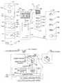
- FIG. 3Aillustrates one embodiment of the development system 222 .
- a development system 222 acomprises an applicator station 300 and a development station 302 .
- the applicator station 300operates to apply a relatively uniform coating of a processing solution 304 to the film 106 .
- the processing solution 304comprises a color developer solution, such as Flexicolor Developer for Process C-41 available from the Eastman Kodak Company.
- the processing solution 304comprises other suitable solutions.
- the processing solution 304may comprise a monobath solution that acts as a developer and stop solution.
- the applicator station 300comprises an applicator 306 , a fluid delivery system 308 , and a reservoir 310 .
- the applicator 306operates to coat the film 306 with the processing solution 304 .
- the applicator 306comprises a slot coater device.
- the applicator 306comprises an ink jet applicator, a tank, an aerosol applicator, drip applicator, sponge applicator, or any other suitable device for applying the processing solution 304 to the film 106 .
- the fluid delivery system 308delivers the processing solution 304 from the reservoir 310 to the applicator 306 .
- the fluid delivery system 308generally delivers the processing solution 304 at a constant volumetric flow rate to help insure uniformity of coating of processing solution 304 on the film 106 .
- the reservoir 310contains a sufficient volume of processing solution 304 to process multiple rolls of film 106 .
- the reservoir 210comprises a replaceable cartridge.
- the reservoir 310comprises a refillable tank.
- the applicator station 300may comprise other suitable systems and devices for applying the processing solution 304 to the film 106 .
- the development station 302operates to give the film 106 time to develop prior to being scanned by the scanning system 224 .
- the development station 302forms that portion of the transport system 220 between the applicator 306 and the scanning system 224 .
- the length of the development station 302is generally dependent upon the development time of the film 106 . In particular, depending upon the environment and chemical nature of the processing solution 304 , development of the film 106 may require as little as a few seconds to as long as several minutes.
- the development station 302comprises a cover 312 that protects the film 106 during development.
- the cover 312forms an environmental chamber 314 surrounding the film 106 .
- the temperature and humidity within the environmental chamber 314are strictly controlled.
- the environmental chamber 314has a minimum volume surrounding the film 106 .
- the cover 312may be insulated to maintain a substantially constant temperature as the film 106 is developed.
- the development station 302preferably includes a heating system 316 .
- the heating system 316may include a heated roller 318 and heating element 320 .
- the heating system 316may include a processing solution heating system (not expressly shown) that heats the processing solution 304 prior to its application to the film 106 .
- the development system 222includes a processing station 322 .
- the processing station 322operates to further process the film 106 prior to being scanned by the scanning system 224 .
- the processing station 322operates to modify the metallic silver grains and or silver halide in the film 106 . Modifying the silver within the film 106 decreases the opacity of the film 106 , thereby improving the transmissivity of light through the film 106 .
- the processing station 322operates to retard or substantially reduce the continued development of the film 106 . Retarding or substantially stopping the continued development of the film 106 increases the amount of time the film 106 can be exposed to visible light without substantially fogging of the film 106 .
- the processing station 322operates to modify the silver and also substantially reduce the continued development of the film 106 .
- FIGS. 3 B- 1 - 3 B 4illustrate different examples of the processing station 322 .
- transport system 220transports the film 106 through the applicator station 300 .
- Fluid delivery system 308dispenses the processing solution 304 from the reservoir 310 through the applicator 306 onto the film 106 .
- the processing solution 304initiates development of the dye image and silver image within the film 106 .
- the coated film 106is then transported through the development station 302 .
- the development station 302allows the film 106 time to develop within a controlled environment.
- the film 106is then transported through the processing station 322 where the film 106 is further processed.
- the film 106is then transported by the transport system 220 to the scanning system 224 .
- the processing solution 304 coated on the film 106is not substantially removed, but remains on the film 106 as the film 106 is transported to the scanning system 224 .
- FIG. 3B-1illustrates one embodiment of a processing station 322 a .
- the processing station 322 acomprises one or more applicator stations 323 that operate to apply one or more processing solutions 324 to the film 106 .
- the applicator station 323comprises an applicator 306 b , a fluid delivery system 308 b , and a reservoir 310 b , similar in function and design as applicator station 300 described in FIG. 3 A.
- the processing station 322 amay comprise any number of applicator stations 323 as required to apply suitable processing solutions 324 to the film 106 .
- the processing solution 324may comprise any suitable chemical applied to the film 106 to further process the film 106 .
- the processing solution 324includes a fixing agent.
- the fixing agentdissolves the silver halide into a substantially transparent silver compound. This has the effect of slightly reducing the opacity of the film 106 , but substantially eliminating the sensitivity of the film 106 to any type of light.
- the processing solution 324includes a bleaching agent. The bleaching agent converts the metallic silver within the film 106 into silver halide. As a result, the opacity of the film 106 is greatly reduced, but the sensitivity of the film 106 to light is not substantially reduced.
- both a bleaching agent and a fixing agentare applied to the film 106 , individually or as a mixture referred to as blix (combines functions of a bleaching and fixing) is applied to the film 106 .
- the processing solution 324may also include an aqueous solution, stop solution, stabilizer solution, or any other suitable film processing solution without departing from the scope of the invention.
- FIG. 3B-2illustrates a processing station 322 b that operates to chill the developing film 106 . Chilling the developing film 106 substantially slows the chemical developing action of the processing solution 204 .
- the processing station 322 bcomprises an electrical cooling roller 326 and insulation shield 328 .
- the cooling roller 326is electronically maintained at a cool temperature that substantially arrests the chemical reaction of the processing solution 304 .
- the insulation shield 328substantially reduces the environmental heat transfer to the cooling roller 326 .
- the processing station 322 bmay comprise any other suitable system and device for chilling the developing film 106 .
- FIG. 3B-3illustrates a processing station 322 c that operates to dry the processing solution 304 on the coated film 106 . Drying the processing solution 304 substantially stops further development of the film 106 and may also decrease the opacity of the film 106 .
- the processing station 322 ccomprises an optional cooling roller 326 , as described in FIG. 3B-2, and a drying system 330 . Although heating the coated film 106 would facilitate drying the processing solution 304 , the higher temperature would also have the effect of accelerating the chemical reaction of the processing solution 304 and film 106 . Accordingly, in the preferred embodiment, the film 106 is cooled to retard the chemical action of the processing solution 304 and then dried to effectively freeze-dry the coated film 106 .
- heating the film 106 to dry the film 106can also be accomplished by incorporating the accelerated action of the processing solution 304 into the development time for the film 106 .
- a suitable processing solution 324is applied to the film 106
- the chemical action of the processing solution 304is already minimized and the film 106 can be dried using heat without substantially effecting the development of the film 106 .
- the drying system 330circulates air over the film 106 to dry the processing solution 304 and depending upon the embodiment, the processing solution 324 onto the film 106 .
- the processing station 322 cmay comprise any other suitable system for drying the film 106 .
- FIG. 3B-4illustrates a processing station 322 d that operates to substantially remove excess processing solution 304 , and any excess processing solution 324 , from the film 106 .
- the processing station 322 ddoes not remove the solutions 304 , 324 that are absorbed into the film 106 .
- the film 106includes some processing solutions 304 , 324 , and does not substantially remove any silver compounds within the film 106 . Removing any excess processing solution 304 will retard the continued development of the film 106 .
- wiping any excess processing solutions 304 , 324 from the film 106may improve the light reflectance and transmissivity properties of the coated film 106 .
- the processing station 322 dcomprises a wiper 332 operable to substantially remove excess processing solution 304 and any processing solution 324 .
- the wiper 332includes an absorbent material that wicks away the excess processing solutions 304 , 324 .
- the wiper 332comprises a squeegee that mechanically removes substantially all the excess processing solutions 304 , 324 .
- the processing station 322 dmay comprise any suitable device or system operable to substantially remove any excess processing solutions 304 , 324 .
- the processing station 322may comprise any suitable device or system for further processing the film 106 .
- the processing station 322may comprise any suitable combination of the above embodiments.
- the processing station 322may comprise an applicator station 300 b for applying a halt solution 324 , a cooling roller 326 , and a drying system 330 .
- the processing station 322may comprise a wiper 332 and a drying system 330 .
- FIG. 4Aillustrates one embodiment of the scanning system 224 .
- Scanning system 224comprises one or more scanning stations 400 .
- Individual scanning stations 400may have the same or different architectures and embodiments.
- Each scanning station 400comprises a lighting system 402 and a sensor system 404 .
- the lighting system 402includes one or more light sources 406 and optional optics 408 .
- the sensor system 404includes one or more detectors 410 and optional optics 412 .
- the lighting system 402operates to produce suitable light 420 that is directed onto the film 106 .
- the sensor system 404operates to measure the light 420 from the film 106 and produce sensor data 206 that is communicated to the to the data processing system 202 .
- Each scanning station 400utilizes electromagnetic radiation, i.e., light, to scan the film 106 .
- Individual scanning stations 400may have different architectures and scan the film 106 using different colors, or frequency bands (wavelengths), and color combinations. In particular, different colors of light interact differently with the film 106 . Visible light interacts with the dye image and silver within the film 106 . Whereas, infrared light interacts with the silver, but the dye image is generally transparent to infrared light.
- coloris used to generally describe specific frequency bands of electromagnetic radiation, including visible and non-visible light.
- Visible lightmeans electromagnetic radiation having a wavelength or band generally within the electromagnetic spectrum of near infrared light (>700 nm) to near ultraviolet light ( ⁇ 400 nm). Visible light can be separated into specific bandwidths.
- the color redis generally associated with light within a frequency band of approximately 600 nm to 700 nm
- the color greenis generally associated with light within a frequency band of approximately 500 nm to 600 nm
- the color blueis generally associated with light having a wavelength of approximately 400 nm to 500 nm.
- Near infrared lightis generally associated with radiation having a wavelength of approximately 700 nm to 1500 nm.
- specific colors and wavelengthsare described herein, the scanning station 400 may utilize other suitable colors and wavelengths (frequency) ranges without departing from the spirit and scope of the invention.
- the light source 406may comprise one or more devices or a system that produces suitable light 420 .
- the light source 406comprises an array of light-emitting diodes (LEDs).
- LEDslight-emitting diodes
- different LEDs within the arraymay be used to produce different colors of light 420 , including infrared light.
- specific colors of LEDscan be controlled to produce short duration pulses of light 420 .
- the light source 406comprises a broad spectrum light source 406 , such as a fluorescent, incandescent, tungsten-halogen, direct gas discharge lamps, and the like.
- the sensor system 404may include filters for spectrally separating the colors of light 420 from the film 106 .
- a RGB filtered trilinear array of detectorsmay be used to spectrally separate the light 420 from the film 106 .
- the light source 406includes a filter, such as a color wheel, to produce the specified colors of light 420 .
- the light source 406comprises a point light source, such as a laser.
- the point light sourcemay be a gallium arsenide or an indium gallium phosphide laser.
- the width of the laser beamis preferably the same size as a pixel on the film 106 ( ⁇ 12 microns).
- Filters, such as a color wheel, or other suitable wavelength modifiers or limitersmaybe used to provide the specified color or colors of light 420 .
- Optional optics 408 for the lighting system 402directs the light 420 to the film 106 .
- the optics 408comprises a waveguide that directs the light 420 onto the film 106 .
- the optics 408includes a lens system for focusing the light 420 .
- the lens systemincludes a polarizing filter to condition the light 420 .
- the optics 408may also include a light baffle 422 a .
- the light baffle 422 aconstrains illumination of the light 420 within a scan area in order to reduce light leakage that could cause fogging of the film 106 .
- the light baffle 422 acomprises a coated member adjacent the film 106 .
- the coatingis generally a light absorbing material to prevent reflecting light 420 that could cause fogging of the film 106 .
- the detector 410comprises one or more photodetectors that convert light 420 from the film 106 into data signals 216 .
- the detector 410comprises a linear charge coupled device (CCD) array.
- the detector 410comprises an area array.
- the detector 410may also comprise a photodiode, phototransistor, photoresistor, and the like.
- the detector 410may utilize time delay integration (TDI) to improve the accuracy detector 410 .
- the detector 410may include filters to limit the bandwidth, or color, detected by individual photodetectors. For example, a trilinear array often includes separate lines of photodetectors with each line of photodetectors having a color filter to allow only one color of light to be measured by the photodetector.
- the arrayin a trilinear array, generally includes individual red, green, and blue filters over separate lines in the array. This allows the simultaneous measurement of red, green, and blue components of the light 420 .
- Other suitable types of filtersmay be used.
- a hot mirror and a cold mirrorcan be used to separate infrared light from visible light.
- Optional optics 412 for the sensor system 404directs the light 420 from the film 106 onto the detector 410 .
- the optics 412comprises a lens system that directs the light 420 from the film 106 onto the detector 410 .
- the optics 412include polarized lenses.
- the optics 412may also include a light baffle 422 b .
- the light baffle 422 bis similar in function to light baffle 422 a to help prevent fogging of the film 106 .
- light 420 sensed by the sensor system 404may be transmitted light or reflected light.
- Light 420 reflected from the film 106is generally representative of the emulsion layer on the same side of the film 106 as the sensor system 404 .
- light 420 reflected from the front side (emulsion side) of the film 106represents the blue sensitive layer and light 420 reflected from the back side of the film 106 represents the red sensitive layer.
- Light 420 transmitted through the film 106collects information from all layers of the film 106 . Different colors of light 420 are used to measure different characteristics of the film 106 . For example, visible light interacts with the dye image and silver within the film 106 , and infrared light interacts with the silver in the film 106 .
- the lighting system 402 and sensor system 404operate in concert to illuminate and sense the light 420 from the film 106 to produce suitable sensor data 206 .
- the lighting system 402separately applies distinct colors of light 420 to the film 106 .
- the sensor system 404generally comprises a non-filtered detector 410 that measures in series the corresponding colors of light 420 from the film 106 .
- multiple unique color combinationsare simultaneously applied to the film 106 , and individual color records are derived from the sensor data 206 .
- the lighting system 402simultaneously applies multiple colors of light 420 to the film 106 .
- the sensor system 404generally comprises a filtered detector 410 that allows the simultaneous measurement of individual colors of light 420 .
- Other suitable scanning methodsmay be used to obtain the required color records.
- the use of the processing station 322may improve the scanning properties of the film 106 in addition to retarding or substantially stopping the continued development of the film 106 .
- the amount of light 420 transmitted through the film 106is negatively affected by the opacity of the film 106 .
- Both the silver image and silver halide within the film 106occlude light 420 . On the whole, the silver image within the film 106 absorbs light 420 , and the silver halide reflects light 420 .
- the processing solutions 324may be used to modify opacity of the film 106 and improve the scanning properties of the film 106 .
- FIGS. 4 B- 1 - 4 B- 4Specific examples of scanner station 400 architectures are illustrated in FIGS. 4 B- 1 - 4 B- 4 .
- the scanning system 224may comprise any illustrated example, combination of examples, or other suitable methods or systems for scanning the film 106 without departing from the scope and spirit of the invention.
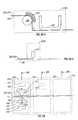
- FIG. 4B-1illustrates one embodiment of a scanning station 400 a having a transmission architecture.
- the transmission scanning station 400 acomprises a lighting system 402 a and a sensor system 404 a .
- Lighting system 402 aproduces light 420 a that is transmitted through the film 106 and measured by the sensor system 404 a .
- the sensor system 404 aproduces sensor data 206 a that is communicated to the data processing system 202 .
- Lighting system 402 a and sensor system 404 aare similar in design and function as lighting system 402 and sensor system 404 , respectively.
- the visible light 420 amay comprise broadband visible light, individual visible light colors, or combinations of visible light colors.
- the sensor system 404 awill preferably comprise a red, green and blue tri-linear array.
- the sensor system 404 acan simultaneously measure the red, green and blue components of light 420 a from the film 106 .
- the light 420 acomprises pulses of red, green and blue light
- the sensor system 404 apreferably comprises an unfiltered detector operable to measure the pulses of light 420 a from the film 106 .
- the color of the light 420 achanges and the sensor system 404 a measures the respective light pulses from the film 106 .
- the light 420 a produced by the lighting system 402 acomprises visible light.
- the visible light 420 ainteracts with at least one dye cloud within the film 106 and any silver occlusions contained in the film 106 .
- the film 106may include silver forming an optical occlusion, such as metallic silver grains, silver halide, or both, but does not include silver compounds formed as a result of fixing the silver halide contained within the film 106 .
- the visible light 420 ainteracts with the magenta, cyan and yellow dye images within the film 106 , as well as any silver occlusions within the film 106 , the sensor system 404 a records the intensity of visible light 420 a from the film 106 and produces sensor data 206 a .
- the sensor data 206 agenerally comprises a red, green, and blue record corresponding to the cyan, magenta, and yellow dye images, respectively.
- each of the red, green, and blue recordsmay include a silver record.
- any metallic silver grains or silver halide within the film 106partially occludes the visible light 420 a transmitted through the film 106 .
- the red, green, and blue recordsare processed by the data processing system 102 to correct for the occlusion in the film 106 .
- the light 420 a produced by the lighting system 402 acomprises visible light and infrared light.
- the visible lightmay comprise broadband visible light, individual visible light colors, or combinations of visible light colors.
- the infrared lightmay comprise infrared, near infrared, or any suitable combination thereof.
- the visible light 420 ainteracts with the dye images, i.e. cyan, magenta, or yellow, within the film 106 and any silver to produce a red, green, and/or blue record that includes a silver record.
- the infrared lightinteracts with the silver, and any other occlusions, within the film 106 and produces a silver record.
- the silver recordcan then be used to remove, at least in part, the effects of the occlusions contained in the red, green, and blue records.
- This embodimentis analogous to the defect correction electronic scanners described in U.S. Pat. No. 5,266,805, entitled System and Method for Image Recovery, which is hereby incorporated herein by reference.
- any occlusions within the filmare analogous to defects that obstruct the optical path of the infrared light.
- the degree of occlusionis used as a basis for modifying the color records. For example, in pixels having a high occlusion density, the individual color records are significantly increased, whereas in pixels having a low occlusion density, the individual color records are relatively unchanged.
- the light produced by the lighting system 402 acomprises only infrared and/or near infrared light.
- the infrared light 420 ainteracts with occlusions within the film 106 but does not substantially interact with the dye images within the film 106 .
- the sensor data 206 adoes not spectrally distinguish the magenta, cyan, and yellow dye images.
- An advantage of this embodimentis that the infrared light 420 a does not fog the film 106 .
- the advantage of not fogging the film 106allows the film 106 to be scanned at multiple development times without significantly fogging the film 106 .
- the scanning station 400 acan be used to determine the optimal development time for the film 106 . This embodiment may also be used to scan the silver image.
- FIG. 4B-1illustrates the light 420 a being transmitted through the film 106 from the backside to the front side of the film 106 .
- the light 420 acan also be transmitted through the film 106 from the front side to the backside of the film 106 without departing from the scope of the invention.
- FIG. 4B-2illustrates one embodiment of a scanning station 400 b having a reflective architecture.
- the reflective scanning station 400 bcomprises a lighting system 402 b and a sensor system 404 b .
- Lighting system 402 bproduces light 420 b that is reflected from the film 106 and measured by the sensor system 404 b .
- the scanning station 400 bgenerally requires silver halide to be present within the film 106 .
- the silver halidescatters and reflects the light 420 b measured by the sensor system 404 b .
- the sensor system 404 bproduces sensor data 206 b that is communicated to the data processing system 202 .
- Lighting system 402 b and sensor system 404 bare similar to lighting system 402 and sensor system 404 , respectively.
- the light 420 b produced by the lighting system 402 bcomprises blue light.
- the blue light 420 bscans the silver and dye image within the blue layer of the film 106 .
- the blue light 420 binteracts with the yellow dye image and also the silver in the blue emulsion layer.
- the blue light 420 bis reflected from the silver halide and measured by the sensor system 404 b to produce a blue record.
- Many conventional filmsinclude a yellow filter below the blue emulsion layer that blocks the blue light 420 a from illuminating the other emulsion layers of the film 106 . As a result, noise created by cross-talk between the blue emulsion layer and the red and green emulsion layers is substantially reduced.
- the light 420 b produced by the lighting system 402 bcomprises non-blue light. It has been determined that visible light other than blue light interacts in substantially the same manner with the various emulsion layers. In this embodiment, infrared light also interacts in substantially the same manner as non-blue light, with the exception that infrared light will not fog the emulsion layers of the film 106 . In this embodiment, the non-blue light 420 b interacts with the silver image in the blue emulsion layer of the film 106 , but is transparent to the yellow dye within the blue emulsion layer of the film 106 . This embodiment is prone to higher noise levels created by cross-talk between the blue and green emulsion layers of the film 106 .
- the light 420 b produced by the lighting system 402 bcomprises visible and infrared light.
- blue lightinteracts with the yellow dye image and the silver image in the blue emulsion layer
- green lightinteracts with magenta dye image and the silver in each of the emulsion layers
- red lightinteracts with the cyan dye image and the silver in each of the emulsion layers
- the infrared lightinteracts with the silver in each emulsion layer of the film 106 .
- the sensor system 404 bgenerally comprises a filtered detector 410 b (not expressly shown) that measures the red, green, blue, and infrared light 420 b from the film 106 to produce red, green, blue, and infrared records as sensor data 206 b.
- the scanning station 400 bis illustrated with the lighting system 402 b and the sensor system 404 b located on front side of the film 106 , the lighting system 402 b and the sensor system 404 b may also be located on the back side of the film 106 .
- the light 420 b produced by the lighting system 402 bmay comprise red light. The red light largely interacts with the cyan dye image and silver in the red emulsion layer of the film 106 to produce a red record of the sensor data 206 b.
- FIG. 4B-3illustrates one embodiment of a scanning station 400 c having a transmission-reflection architecture.
- the transmission-reflection architectureis the preferred embodiment of the scanning system 224 .
- the scanning station 400 ccomprises a first lighting system 402 c , a second lighting system 402 d , and a sensor system 404 c .
- the lighting system 402 coperates to illuminate the front side of the film 106 with light 420 c
- the second lighting system 402 doperates to illuminate the backside of the film 106 with light 420 d
- the sensor system 404 coperates to measure the light 420 c reflected from the film 106 and the light 420 d transmitted through the film 106 .
- the sensor system 404 cBased on the measurements of the light 420 b , 420 d , the sensor system 404 c produces sensor data 206 c that is communicated to the data processing system 102 .
- Lighting system 402 c and 402 dare similar to lighting system 402
- sensor system 404 cis similar to the sensor system 404
- scanning station 400 cis illustrated with lighting systems 402 c , 402 d
- a single light sourcemay be used to produce light that is directed through a system of mirrors, shutters, filters, and the like, to illuminate the film 106 with the front side of the film 106 with light 420 c and illuminate the back side of the film 106 with light 420 d .
- the light 420 c , 420 dmay comprise any color or color combinations, including infrared light.
- This embodiment of the scanning station 400 cutilizes many of the positive characteristics of the transmission architecture scanning station 400 a and the reflection architecture scanning station 400 b .
- the blue emulsion layeris viewed better by light 420 c reflected from the film 106 than by light 420 d transmitted through the film 106 ;
- the green emulsion layeris viewed better by light 420 d transmitted through the film 106 than by light 420 c reflected from the film 106 ;
- the red emulsion layeris adequately viewed by light 420 d transmitted through the film 106 .
- the cost of the scanning station 400 cis minimized through the use of a single sensor system 404 c.
- the light 420 ccomprises blue light
- light 420 dcomprises red, green, and infrared light.
- the blue light 420 cinteracts with the yellow dye image and silver in the blue emulsion layer of the film 106 .
- the sensor system 404 cmeasures the light 420 c from the film 106 and produces a blue-silver record.
- the red and green light 420 dinteracts with the cyan and magenta dye images, respectively, as well as the silver in the film 106 .
- the infrared light 420 dinteracts with the silver, but does not interact with the dye clouds within the film 106 .
- the silver contained within the film 106may comprise silver grains, silver halide, or both.
- the red, green, and infrared light 420 d transmitted through the film 106is measured by the sensor system 404 c , which produces a red-silver, green-silver, and silver record.
- the blue-silver, red-silver, green-silver, and silver recordsform the sensor data 206 c that is communicated to the data processing system 202 .
- the data processing system 202utilizes the silver record to facilitate removal of the silver component from the red, green, and blue records.
- the light 420 ccomprises blue light and infrared light
- light 420 dcomprises red, green, and infrared light.
- the blue light 420 cmainly interacts with the yellow dye image and silver within the blue emulsion layer of the film 106 .
- the infrared light 420 cinteracts with mainly the silver in the blue emulsion layer of the film 106 .
- the sensor system 404 cmeasures the blue and infrared light 420 c from the film 106 and produces a blue-silver record and a front side silver record, respectively.
- the red, green, and infrared light 420 dinteract with the film 106 and are measured by the sensor system 404 c to produce red-silver, green-silver and transmitted-silver records as discussed above.
- the blue-silver, red-silver, green-silver, and both silver recordsform the sensor data 206 c that is communicated to the data processing system 202 .
- the data processing system 202utilizes the front side silver record of the blue emulsion layer to facilitate removal of the silver component from the blue-silver record, and the transmission-silver record is utilized to facilitate removal of the silver component from the red and green records.
- the scanning station 400 cis described in terms of specific colors and color combinations of light 420 c and light 420 d , the light 420 c and light 420 d may comprise other suitable colors and color combinations of light without departing from the scope of the invention.
- light 420 cmay comprise non-blue light, infrared light, broadband white light, or any other suitable light.
- light 420 dmay include blue light, broadband white light, or another other suitable light.
- Scanning station 400 cmay also comprise other suitable embodiments without departing from the scope of the invention.
- the scanning station 400 cis illustrated with two lighting systems 402 and a single sensor system 404 , the scanning station 400 c could be configured with a single lighting system 402 and two sensor systems 404 , wherein one sensor system measures light 420 reflected from the film 106 and the second sensor system 404 measures light 420 transmitted through the film 106 .
- the scanning station 400may comprise a single lighting system that illuminates the film 106 with light 420 c and light 420 d.
- FIG. 4B-4illustrates an embodiment of a scanning station 400 d having a reflection-transmission-reflection architecture.
- the scanning station 400 dcomprises a first lighting system 402 e , a second lighting system 402 f , a first sensor system 404 e , and a second sensor system 404 f .
- the lighting system 402 eoperates to illuminate the front side of the film 106 with light 420 e
- the second lighting system 402 foperates to illuminate the back side of the film 106 with light 420 f .
- the first sensor system 404 eoperates to measure the light 420 e reflected from the film 106 and the light 420 f transmitted through the film 106
- the second sensor system 404 foperates to measure the light 420 f reflected from the film 106 and the light 420 e transmitted through the film 106
- the sensor systems 404 e , 404 fBased on the measurements of the light 420 e and 420 f , the sensor systems 404 e , 404 f produce sensor data 206 ef that is communicated to the data processing system 202 .
- Lighting systems 402 e , 402 fare similar to lighting systems 402
- sensor systems 404 e , 404 fare similar to the sensor system 404 .
- scanning station 400 dis illustrated with lighting systems 402 e , 402 f , and sensor systems 404 e , 404 f , a single lighting system and/or sensory system, respectively, may be used to produce light that is directed through a system of mirrors, shutters, filters, and the like, to illuminate the film 106 with the front side of the film 106 with light 420 e and illuminate the backside of the film 106 with light 420 f.
- This embodiment of the scanning station 400 dexpands upon the positive characteristics of the transmission-reflection architecture of scanning station 400 c .
- the blue emulsion layeris viewed better by light 420 e reflected from the film 106 and the green emulsion layer is viewed better by light 420 e or 420 f transmitted through the film 106 .
- Second sensor system 404 fallows viewing of the red emulsion layer by light 420 f reflected from the film 106 , which generally produces better results than viewing the red emulsion layer by light 420 e or light 420 f transmitted through the film 106 .
- the light 420 e and 420 fcomprises light within the infrared portion of the electromagnetic spectrum.
- the sensor system 404 emeasures light 420 e reflected from the front emulsion layer and light 420 f transmitted through the film 106 .
- the sensor system 404 fmeasures light 420 f reflected from the back emulsion layer and light 420 e transmitted through the film 106 .
- the front measurementcorresponds to the blue signal
- the back measurementcorresponds to the red signal
- the through measurement minus the front and back measurementcorresponds to the green signal.
- cross-talkexists between the emulsion layers, as the emulsion layers are not spectrally unique using infrared light.
- the sensor systems 404 e , 404 finclude a trilinear array of filtered detectors, and the light 420 e and the light 420 f comprises broadband white light and infrared light.
- the trilinear arrayoperates to simultaneously measure the individual red, green, and blue components of the broadband white light 420 e , 420 f .
- the infrared lightis measured separately and can be measured through each filtered detector 410 of the sensor systems 404 e , 404 f .
- the broadband white light 420 e , 420 finteracts with the silver and magenta, cyan, and yellow color dyes in the film 106 , respectively, and the infrared light 420 e , 420 f interacts with the silver within the film 106 .
- the reflected white light 420 e measured by the first sensor system 404 eincludes information corresponding to the yellow dye image and the silver in the blue emulsion layer of the film 106 .
- the blue component of the broadband white light 420 e measured by the blue detector of the sensor system 404 ecorresponds to the yellow dye image
- the non-blue components of the broadband white light 420 e measured by the red and green detectorscorresponds to the red and green dye images and all the silver within the emulsion layers of the film 106
- the red component of the broadband white light 420 f measured by the red detector of the sensor system 404 fcorresponds largely to the cyan dye image
- the non-red components of the broadband white light 420 e measured by the blue and green detectorscorresponds to the yellow and magenta dye images and all the silver within the emulsion layers of the film 106 .
- the white light 420 e , 420 f transmitted through the film 106interacts with each color dye image and silver within the film 106 , and the red, green, and blue light components are measured by the red, green, and blue detectors of the sensor systems 404 e , 404 f to produce individual red, green and blue light records that include the silver record.
- the infrared light 420 e reflected from the film 106 and measured by the sensor system 404 ecorresponds largely to the silver in the blue emulsion layer of the film 106
- the infrared light 4201 reflected from the film 106 and measured by the sensor system 404 flargely corresponds to the silver in the red emulsion layer of the film 106 .
- the infrared light 420 e , 420 f transmitted through the film 106 measured by the sensor systems 404 e , 404 fcorresponds to the silver in the red, green, and blue emulsion layers of the film 106 .
- the individual measurements of the sensor systems 404 e , 404 fare communicated to the data processing system 202 as sensor data 206 ef .
- the data processing system 202processes the sensor data 206 ef and constructs the digital image 108 using the various sensor system measurements.
- the blue signal value for each pixelcan be calculated using the blue detector data from the reflected light 420 e and the blue detector data from the transmitted light 420 f , as modified by non-blue detector data from the reflected light 420 e , and the non-blue detector data from the transmitted light 420 e or 420 f .
- the red and green signal values for each pixelcan be similarly calculated using the various measurements.
- the sensor systems 404 e , 404 finclude a trilinear array of filtered detectors, and the light 420 e and the light 420 f comprises broadband white light.
- This embodiment of the scanning station 400 doperates in a similar manner as discussed above, with the exception that infrared light is not measured or used to calculate the digital image 108 .
- the scanning station 400 dis described in terms of a specific colors and color combinations of light 420 e and light 420 f , the light 420 e and light 420 f may comprise other suitable colors and color combinations of light without departing from the scope of the invention. Likewise, the scanning station 400 d may comprise other suitable devices and systems without departing from the scope of the invention.
Landscapes
- Engineering & Computer Science (AREA)
- Multimedia (AREA)
- Signal Processing (AREA)
- Human Computer Interaction (AREA)
- Physics & Mathematics (AREA)
- General Physics & Mathematics (AREA)
- Projection-Type Copiers In General (AREA)
- Facsimiles In General (AREA)
Abstract
Description
Claims (95)
Priority Applications (1)
| Application Number | Priority Date | Filing Date | Title |
|---|---|---|---|
| US09/778,023US6786655B2 (en) | 2000-02-03 | 2001-02-05 | Method and system for self-service film processing |
Applications Claiming Priority (3)
| Application Number | Priority Date | Filing Date | Title |
|---|---|---|---|
| US18048000P | 2000-02-03 | 2000-02-03 | |
| US18047900P | 2000-02-03 | 2000-02-03 | |
| US09/778,023US6786655B2 (en) | 2000-02-03 | 2001-02-05 | Method and system for self-service film processing |
Publications (2)
| Publication Number | Publication Date |
|---|---|
| US20010033752A1 US20010033752A1 (en) | 2001-10-25 |
| US6786655B2true US6786655B2 (en) | 2004-09-07 |
Family
ID=26876361
Family Applications (1)
| Application Number | Title | Priority Date | Filing Date |
|---|---|---|---|
| US09/778,023Expired - Fee RelatedUS6786655B2 (en) | 2000-02-03 | 2001-02-05 | Method and system for self-service film processing |
Country Status (3)
| Country | Link |
|---|---|
| US (1) | US6786655B2 (en) |
| AU (1) | AU2001236694A1 (en) |
| WO (1) | WO2001095028A2 (en) |
Cited By (40)
| Publication number | Priority date | Publication date | Assignee | Title |
|---|---|---|---|---|
| US20010037381A1 (en)* | 2000-04-26 | 2001-11-01 | Eastman Kodak Company | Process for making digital images available to a user on a server |
| US20010041072A1 (en)* | 2000-05-11 | 2001-11-15 | Konica Corporation | Photo-service system and image input apparatus |
| US20020033959A1 (en)* | 2000-08-02 | 2002-03-21 | Jitsuhiko Ando | Image printing system and image printing apparatus |
| US20020040303A1 (en)* | 2000-10-02 | 2002-04-04 | Toshihiro Hamamura | Storage medium, and digital camera and image handling device using said storage medium |
| US20020131080A1 (en)* | 2001-03-19 | 2002-09-19 | Jun Enomoto | Print system |
| US20020140978A1 (en)* | 2001-02-16 | 2002-10-03 | Hitoshi Urabe | Image storing apparatus and image storing program |
| US20030048282A1 (en)* | 2001-09-07 | 2003-03-13 | Grindstaff Gene Arthur | Concealed object recognition |
| US20030108347A1 (en)* | 2001-12-07 | 2003-06-12 | Manico Joseph A. | Method of using a portable system for capturing images |
| US20040044535A1 (en)* | 2002-09-03 | 2004-03-04 | Conner Erin L. | Systems and methods for a digital information automated teller machine |
| US20040118914A1 (en)* | 2001-09-24 | 2004-06-24 | E2Interactive, Inc. D/B/A E2Interactive, Inc. | System & method for distributing stored-value cards |
| US20040189807A1 (en)* | 2003-03-28 | 2004-09-30 | Smith Greg S. | System and method of capturing and providing supplemental data associated with a digital image |
| US20040215477A1 (en)* | 2002-12-12 | 2004-10-28 | Martin Douglas A. | Methods and systems for providing consumer services including coin-counting and digital image printing |
| US20050158046A1 (en)* | 2004-01-21 | 2005-07-21 | Silverbrook Research Pty Ltd | Hybrid digital photofinishing system |
| US20060275033A1 (en)* | 2004-01-21 | 2006-12-07 | Silverbrook Research Pty Ltd | Print media and printing fluid cartridge of digital photofinishing system |
| US7587085B2 (en) | 2004-10-28 | 2009-09-08 | Fotonation Vision Limited | Method and apparatus for red-eye detection in an acquired digital image |
| US7599577B2 (en)* | 2005-11-18 | 2009-10-06 | Fotonation Vision Limited | Method and apparatus of correcting hybrid flash artifacts in digital images |
| US7617982B1 (en)* | 2003-09-10 | 2009-11-17 | Ncr Corporation | Computer peripheral with integrated printer and bar code reader |
| US7630006B2 (en) | 1997-10-09 | 2009-12-08 | Fotonation Ireland Limited | Detecting red eye filter and apparatus using meta-data |
| US20100002063A1 (en)* | 2004-01-21 | 2010-01-07 | Silverbrook Research Pty Ltd | Printing System Having Duplex Dryer |
| US7689009B2 (en) | 2005-11-18 | 2010-03-30 | Fotonation Vision Ltd. | Two stage detection for photographic eye artifacts |
| US20100142808A1 (en)* | 2007-01-19 | 2010-06-10 | Sitaram Bhagavat | Identifying banding in digital images |
| US7738015B2 (en) | 1997-10-09 | 2010-06-15 | Fotonation Vision Limited | Red-eye filter method and apparatus |
| US7916190B1 (en) | 1997-10-09 | 2011-03-29 | Tessera Technologies Ireland Limited | Red-eye filter method and apparatus |
| US7920723B2 (en) | 2005-11-18 | 2011-04-05 | Tessera Technologies Ireland Limited | Two stage detection for photographic eye artifacts |
| US7962629B2 (en) | 2005-06-17 | 2011-06-14 | Tessera Technologies Ireland Limited | Method for establishing a paired connection between media devices |
| US7965875B2 (en) | 2006-06-12 | 2011-06-21 | Tessera Technologies Ireland Limited | Advances in extending the AAM techniques from grayscale to color images |
| US7970182B2 (en) | 2005-11-18 | 2011-06-28 | Tessera Technologies Ireland Limited | Two stage detection for photographic eye artifacts |
| US7995804B2 (en) | 2007-03-05 | 2011-08-09 | Tessera Technologies Ireland Limited | Red eye false positive filtering using face location and orientation |
| US8000526B2 (en) | 2007-11-08 | 2011-08-16 | Tessera Technologies Ireland Limited | Detecting redeye defects in digital images |
| US8036460B2 (en) | 2004-10-28 | 2011-10-11 | DigitalOptics Corporation Europe Limited | Analyzing partial face regions for red-eye detection in acquired digital images |
| US8055067B2 (en) | 2007-01-18 | 2011-11-08 | DigitalOptics Corporation Europe Limited | Color segmentation |
| US8081254B2 (en) | 2008-08-14 | 2011-12-20 | DigitalOptics Corporation Europe Limited | In-camera based method of detecting defect eye with high accuracy |
| US8126208B2 (en) | 2003-06-26 | 2012-02-28 | DigitalOptics Corporation Europe Limited | Digital image processing using face detection information |
| US8170294B2 (en) | 2006-11-10 | 2012-05-01 | DigitalOptics Corporation Europe Limited | Method of detecting redeye in a digital image |
| US8184900B2 (en) | 2006-02-14 | 2012-05-22 | DigitalOptics Corporation Europe Limited | Automatic detection and correction of non-red eye flash defects |
| US8212864B2 (en) | 2008-01-30 | 2012-07-03 | DigitalOptics Corporation Europe Limited | Methods and apparatuses for using image acquisition data to detect and correct image defects |
| US8503818B2 (en) | 2007-09-25 | 2013-08-06 | DigitalOptics Corporation Europe Limited | Eye defect detection in international standards organization images |
| US8520093B2 (en) | 2003-08-05 | 2013-08-27 | DigitalOptics Corporation Europe Limited | Face tracker and partial face tracker for red-eye filter method and apparatus |
| US8751294B2 (en) | 2009-12-04 | 2014-06-10 | E2Interactive, Inc. | Processing value-ascertainable items |
| US9412007B2 (en) | 2003-08-05 | 2016-08-09 | Fotonation Limited | Partial face detector red-eye filter method and apparatus |
Families Citing this family (9)
| Publication number | Priority date | Publication date | Assignee | Title |
|---|---|---|---|---|
| US8706630B2 (en) | 1999-08-19 | 2014-04-22 | E2Interactive, Inc. | System and method for securely authorizing and distributing stored-value card data |
| US6558051B2 (en)* | 2000-03-17 | 2003-05-06 | Konica Corporation | Film scanning device provided in automatic developing apparatus |
| GB0130817D0 (en)* | 2001-12-22 | 2002-02-06 | Eastman Kodak Co | Image processing |
| FR2835943B1 (en)* | 2002-02-14 | 2005-01-28 | Eastman Kodak Co | METHOD AND SYSTEM FOR CONTROLLING PHOTOGRAPHIC WORK FROM A PORTABLE TERMINAL |
| NO318746B1 (en)* | 2002-02-22 | 2005-05-02 | Vensafe Asa | Consumer goods sales system |
| JP4566679B2 (en)* | 2003-11-13 | 2010-10-20 | キヤノン株式会社 | Image forming apparatus, control method, and program |
| FR2873838B1 (en)* | 2004-07-28 | 2006-11-24 | Fujifilm Sa Sa Lab | INSTALLATION FOR PRODUCTION OF PHOTOGRAPHIC WORKS |
| WO2007028334A1 (en)* | 2005-09-07 | 2007-03-15 | Jun Xiao | Self-service digital image processing system |
| GB2520880A (en)* | 2012-10-09 | 2015-06-03 | Rug Doctor Llc | Kiosk for renting carpet cleaning machines |
Citations (150)
| Publication number | Priority date | Publication date | Assignee | Title |
|---|---|---|---|---|
| US2404138A (en) | 1941-10-06 | 1946-07-16 | Alvin L Mayer | Apparatus for developing exposed photographic prints |
| US3520690A (en) | 1965-06-25 | 1970-07-14 | Fuji Photo Film Co Ltd | Process for controlling dye gradation in color photographic element |
| US3520689A (en) | 1965-06-16 | 1970-07-14 | Fuji Photo Film Co Ltd | Color developing process utilizing pyridinium salts |
| US3587435A (en) | 1969-04-24 | 1971-06-28 | Pat P Chioffe | Film processing machine |
| US3615498A (en) | 1967-07-29 | 1971-10-26 | Fuji Photo Film Co Ltd | Color developers containing substituted nbenzyl-p-aminophenol competing developing agents |
| US3615479A (en) | 1968-05-27 | 1971-10-26 | Itek Corp | Automatic film processing method and apparatus therefor |
| US3617282A (en) | 1970-05-18 | 1971-11-02 | Eastman Kodak Co | Nucleating agents for photographic reversal processes |
| US3747120A (en) | 1971-01-11 | 1973-07-17 | N Stemme | Arrangement of writing mechanisms for writing on paper with a coloredliquid |
| US3833161A (en) | 1972-02-08 | 1974-09-03 | Bosch Photokino Gmbh | Apparatus for intercepting and threading the leader of convoluted motion picture film or the like |
| US3903541A (en) | 1971-07-27 | 1975-09-02 | Meister Frederick W Von | Apparatus for processing printing plates precoated on one side only |
| US3946398A (en) | 1970-06-29 | 1976-03-23 | Silonics, Inc. | Method and apparatus for recording with writing fluids and drop projection means therefor |
| US3959048A (en) | 1974-11-29 | 1976-05-25 | Stanfield James S | Apparatus and method for repairing elongated flexible strips having damaged sprocket feed holes along the edge thereof |
| US4026756A (en) | 1976-03-19 | 1977-05-31 | Stanfield James S | Apparatus for repairing elongated flexible strips having damaged sprocket feed holes along the edge thereof |
| US4081577A (en) | 1973-12-26 | 1978-03-28 | American Hoechst Corporation | Pulsed spray of fluids |
| US4142107A (en) | 1977-06-30 | 1979-02-27 | International Business Machines Corporation | Resist development control system |
| US4215927A (en) | 1979-04-13 | 1980-08-05 | Scott Paper Company | Lithographic plate processing apparatus |
| US4249985A (en) | 1979-03-05 | 1981-02-10 | Stanfield James S | Pressure roller for apparatus useful in repairing sprocket holes on strip material |
| US4265545A (en) | 1979-07-27 | 1981-05-05 | Intec Corporation | Multiple source laser scanning inspection system |
| US4301469A (en) | 1980-04-30 | 1981-11-17 | United Technologies Corporation | Run length encoder for color raster scanner |
| US4490729A (en) | 1982-09-15 | 1984-12-25 | The Mead Corporation | Ink jet printer |
| US4501480A (en) | 1981-10-16 | 1985-02-26 | Pioneer Electronic Corporation | System for developing a photo-resist material used as a recording medium |
| US4564280A (en) | 1982-10-28 | 1986-01-14 | Fujitsu Limited | Method and apparatus for developing resist film including a movable nozzle arm |
| US4594598A (en) | 1982-10-26 | 1986-06-10 | Sharp Kabushiki Kaisha | Printer head mounting assembly in an ink jet system printer |
| US4621037A (en) | 1984-07-09 | 1986-11-04 | Sigma Corporation | Method for detecting endpoint of development |
| US4623236A (en) | 1985-10-31 | 1986-11-18 | Polaroid Corporation | Photographic processing composition applicator |
| US4633300A (en) | 1983-10-21 | 1986-12-30 | Canon Kabushiki Kaisha | Color information detecting device |
| US4636808A (en) | 1985-09-09 | 1987-01-13 | Eastman Kodak Company | Continuous ink jet printer |
| US4666307A (en) | 1984-01-19 | 1987-05-19 | Fuji Photo Film Co., Ltd. | Method for calibrating photographic image information |
| US4670779A (en) | 1984-01-10 | 1987-06-02 | Sharp Kabushiki Kaisha | Color-picture analyzing apparatus with red-purpose and green-purpose filters |
| EP0261782A2 (en) | 1986-08-15 | 1988-03-30 | Konica Corporation | A color image processing apparatus |
| US4736221A (en) | 1985-10-18 | 1988-04-05 | Fuji Photo Film Co., Ltd. | Method and device for processing photographic film using atomized liquid processing agents |
| US4741621A (en) | 1986-08-18 | 1988-05-03 | Westinghouse Electric Corp. | Geometric surface inspection system with dual overlap light stripe generator |
| US4745040A (en) | 1976-08-27 | 1988-05-17 | Levine Alfred B | Method for destructive electronic development of photo film |
| US4755844A (en) | 1985-04-30 | 1988-07-05 | Kabushiki Kaisha Toshiba | Automatic developing device |
| US4777102A (en) | 1976-08-27 | 1988-10-11 | Levine Alfred B | Method and apparatus for electronic development of color photographic film |
| US4796061A (en) | 1985-11-16 | 1989-01-03 | Dainippon Screen Mfg. Co., Ltd. | Device for detachably attaching a film onto a drum in a drum type picture scanning recording apparatus |
| US4814630A (en) | 1987-06-29 | 1989-03-21 | Ncr Corporation | Document illuminating apparatus using light sources A, B, and C in periodic arrays |
| US4821114A (en) | 1986-05-02 | 1989-04-11 | Dr. Ing. Rudolf Hell Gmbh | Opto-electronic scanning arrangement |
| US4845551A (en) | 1985-05-31 | 1989-07-04 | Fuji Photo Film Co., Ltd. | Method for correcting color photographic image data on the basis of calibration data read from a reference film |
| US4851311A (en) | 1987-12-17 | 1989-07-25 | Texas Instruments Incorporated | Process for determining photoresist develop time by optical transmission |
| US4857430A (en) | 1987-12-17 | 1989-08-15 | Texas Instruments Incorporated | Process and system for determining photoresist development endpoint by effluent analysis |
| US4875067A (en) | 1987-07-23 | 1989-10-17 | Fuji Photo Film Co., Ltd. | Processing apparatus |
| US4969045A (en) | 1988-05-20 | 1990-11-06 | Sanyo Electric Co., Ltd. | Image sensing apparatus having automatic iris function of automatically adjusting exposure in response to video signal |
| US4994918A (en) | 1989-04-28 | 1991-02-19 | Bts Broadcast Television Systems Gmbh | Method and circuit for the automatic correction of errors in image steadiness during film scanning |
| EP0422220A1 (en) | 1989-03-28 | 1991-04-17 | Yokogawa Medical Systems, Ltd | Image processing apparatus |
| US5027146A (en) | 1989-08-31 | 1991-06-25 | Eastman Kodak Company | Processing apparatus |
| US5034767A (en) | 1987-08-28 | 1991-07-23 | Hanetz International Inc. | Development system |
| US5101286A (en) | 1990-03-21 | 1992-03-31 | Eastman Kodak Company | Scanning film during the film process for output to a video monitor |
| US5124216A (en) | 1990-07-31 | 1992-06-23 | At&T Bell Laboratories | Method for monitoring photoresist latent images |
| US5155596A (en) | 1990-12-03 | 1992-10-13 | Eastman Kodak Company | Film scanner illumination system having an automatic light control |
| US5196285A (en) | 1990-05-18 | 1993-03-23 | Xinix, Inc. | Method for control of photoresist develop processes |
| US5200817A (en) | 1991-08-29 | 1993-04-06 | Xerox Corporation | Conversion of an RGB color scanner into a colorimetric scanner |
| EP0525886A3 (en) | 1991-07-25 | 1993-05-12 | Eastman Kodak Company | Coater for low flowrate coating |
| US5212512A (en) | 1990-11-30 | 1993-05-18 | Fuji Photo Film Co., Ltd. | Photofinishing system |
| US5231439A (en) | 1990-08-03 | 1993-07-27 | Fuji Photo Film Co., Ltd. | Photographic film handling method |
| US5235352A (en) | 1991-08-16 | 1993-08-10 | Compaq Computer Corporation | High density ink jet printhead |
| US5255408A (en) | 1992-02-11 | 1993-10-26 | Eastman Kodak Company | Photographic film cleaner |
| US5267030A (en) | 1989-12-22 | 1993-11-30 | Eastman Kodak Company | Method and associated apparatus for forming image data metrics which achieve media compatibility for subsequent imaging application |
| US5266805A (en) | 1992-05-05 | 1993-11-30 | International Business Machines Corporation | System and method for image recovery |
| EP0580293A1 (en) | 1992-07-17 | 1994-01-26 | International Business Machines Corporation | Scanning film during the film process |
| US5296923A (en) | 1991-01-09 | 1994-03-22 | Konica Corporation | Color image reproducing device and method |
| EP0601364A1 (en) | 1992-11-30 | 1994-06-15 | Konica Corporation | Film image editing apparatus |
| US5350664A (en) | 1993-02-12 | 1994-09-27 | Eastman Kodak Company | Photographic elements for producing blue, green, and red exposure records of the same hue and methods for the retrieval and differentiation of the exposure records |
| US5350651A (en) | 1993-02-12 | 1994-09-27 | Eastman Kodak Company | Methods for the retrieval and differentiation of blue, green and red exposure records of the same hue from photographic elements containing absorbing interlayers |
| US5357307A (en) | 1992-11-25 | 1994-10-18 | Eastman Kodak Company | Apparatus for processing photosensitive material |
| US5360701A (en) | 1991-01-05 | 1994-11-01 | Ilford Limited | Antistatic backing for photographic roll film |
| US5371542A (en) | 1992-06-23 | 1994-12-06 | The United States Of America As Represented By The Secretary Of The Navy | Dual waveband signal processing system |
| US5391443A (en) | 1991-07-19 | 1995-02-21 | Eastman Kodak Company | Process for the extraction of spectral image records from dye image forming photographic elements |
| US5414779A (en) | 1993-06-14 | 1995-05-09 | Eastman Kodak Company | Image frame detection |
| US5416550A (en) | 1990-09-14 | 1995-05-16 | Eastman Kodak Company | Photographic processing apparatus |
| US5418119A (en) | 1993-07-16 | 1995-05-23 | Eastman Kodak Company | Photographic elements for producing blue, green and red exposure records of the same hue |
| US5418597A (en) | 1992-09-14 | 1995-05-23 | Eastman Kodak Company | Clamping arrangement for film scanning apparatus |
| US5432579A (en) | 1991-10-03 | 1995-07-11 | Fuji Photo Film Co., Ltd. | Photograph printing system |
| US5436738A (en) | 1992-01-22 | 1995-07-25 | Eastman Kodak Company | Three dimensional thermal internegative photographic printing apparatus and method |
| US5440365A (en) | 1993-10-14 | 1995-08-08 | Eastman Kodak Company | Photosensitive material processor |
| EP0669753A2 (en) | 1994-02-28 | 1995-08-30 | Minolta Co., Ltd. | An apparatus for reproducing images |
| US5447811A (en) | 1992-09-24 | 1995-09-05 | Eastman Kodak Company | Color image reproduction of scenes with preferential tone mapping |
| US5448380A (en) | 1993-07-31 | 1995-09-05 | Samsung Electronics Co., Ltd. | color image processing method and apparatus for correcting a color signal from an input image device |
| US5452018A (en) | 1991-04-19 | 1995-09-19 | Sony Electronics Inc. | Digital color correction system having gross and fine adjustment modes |
| US5465155A (en) | 1992-07-17 | 1995-11-07 | International Business Machines Corporation | Duplex film scanning |
| US5477345A (en) | 1993-12-15 | 1995-12-19 | Xerox Corporation | Apparatus for subsampling chrominance |
| EP0482790B1 (en) | 1990-10-23 | 1996-01-03 | Crosfield Electronics Limited | Method and apparatus for generating representation of an image |
| US5496669A (en) | 1992-07-01 | 1996-03-05 | Interuniversitair Micro-Elektronica Centrum Vzw | System for detecting a latent image using an alignment apparatus |
| US5516608A (en) | 1994-02-28 | 1996-05-14 | International Business Machines Corporation | Method for controlling a line dimension arising in photolithographic processes |
| US5519510A (en) | 1992-07-17 | 1996-05-21 | International Business Machines Corporation | Electronic film development |
| US5546477A (en) | 1993-03-30 | 1996-08-13 | Klics, Inc. | Data compression and decompression |
| US5550566A (en) | 1993-07-15 | 1996-08-27 | Media Vision, Inc. | Video capture expansion card |
| US5552904A (en) | 1994-01-31 | 1996-09-03 | Samsung Electronics Co., Ltd. | Color correction method and apparatus using adaptive region separation |
| US5563717A (en) | 1995-02-03 | 1996-10-08 | Eastman Kodak Company | Method and means for calibration of photographic media using pre-exposed miniature images |
| US5568270A (en) | 1992-12-09 | 1996-10-22 | Fuji Photo Film Co., Ltd. | Image reading apparatus which varies reading time according to image density |
| US5576836A (en) | 1993-10-29 | 1996-11-19 | Minolta Co., Ltd. | Multi-picture image printing system |
| US5581376A (en) | 1994-08-29 | 1996-12-03 | Xerox Corporation | System for correcting color images using tetrahedral interpolation over a hexagonal lattice |
| US5587752A (en) | 1995-06-05 | 1996-12-24 | Eastman Kodak Company | Camera, system and method for producing composite photographic image |
| US5596415A (en) | 1993-06-14 | 1997-01-21 | Eastman Kodak Company | Iterative predictor-based detection of image frame locations |
| EP0768571A2 (en) | 1995-09-18 | 1997-04-16 | Noritsu Koki Co., Ltd. | Film connecting device |
| US5627016A (en) | 1996-02-29 | 1997-05-06 | Eastman Kodak Company | Method and apparatus for photofinishing photosensitive film |
| US5649260A (en) | 1995-06-26 | 1997-07-15 | Eastman Kodak Company | Automated photofinishing apparatus |
| US5652936A (en)* | 1996-02-06 | 1997-07-29 | Eastman Kodak Company | Automated photofinishing apparatus with convenient order status checking feature |
| US5664255A (en) | 1996-05-29 | 1997-09-02 | Eastman Kodak Company | Photographic printing and processing apparatus |
| US5664253A (en) | 1995-09-12 | 1997-09-02 | Eastman Kodak Company | Stand alone photofinishing apparatus |
| EP0794454A2 (en) | 1996-03-04 | 1997-09-10 | Fuji Photo Film Co., Ltd. | Film scanner |
| US5667944A (en) | 1995-10-25 | 1997-09-16 | Eastman Kodak Company | Digital process sensitivity correction |
| US5678116A (en) | 1994-04-06 | 1997-10-14 | Dainippon Screen Mfg. Co., Ltd. | Method and apparatus for drying a substrate having a resist film with a miniaturized pattern |
| EP0806861A1 (en) | 1996-05-10 | 1997-11-12 | Noritsu Koki Co., Ltd. | Electronic image printing apparatus attachable to a photographic processing apparatus |
| US5691118A (en) | 1996-10-10 | 1997-11-25 | Eastman Kodak Company | Color paper processing using two acidic stop solutions before and after bleaching |
| US5695914A (en) | 1995-09-15 | 1997-12-09 | Eastman Kodak Company | Process of forming a dye image |
| US5698382A (en) | 1995-09-25 | 1997-12-16 | Konica Corporation | Processing method for silver halide color photographic light-sensitive material |
| US5726773A (en) | 1994-11-29 | 1998-03-10 | Carl-Zeiss-Stiftung | Apparatus for scanning and digitizing photographic image objects and method of operating said apparatus |
| US5739897A (en) | 1994-08-16 | 1998-04-14 | Gretag Imaging Ag | Method and system for creating index prints on and/or with a photographic printer |
| US5771107A (en) | 1995-01-11 | 1998-06-23 | Mita Industrial Co., Ltd. | Image processor with image edge emphasizing capability |
| US5790277A (en) | 1994-06-08 | 1998-08-04 | International Business Machines Corporation | Duplex film scanning |
| US5835795A (en) | 1996-06-25 | 1998-11-10 | Photo Dimensions | Blended photographic composite images |
| US5835811A (en) | 1995-08-31 | 1998-11-10 | Noritsu Koki Co., Ltd. | Photosensitive material processing apparatus |
| EP0878777A2 (en) | 1997-05-09 | 1998-11-18 | Xerox Corporation | Method for enhancement of reduced color set images |
| US5870172A (en) | 1996-03-29 | 1999-02-09 | Blume; Stephen T. | Apparatus for producing a video and digital image directly from dental x-ray film |
| US5880819A (en) | 1995-06-29 | 1999-03-09 | Fuji Photo Film Co., Ltd. | Photographic film loading method, photographic film conveying apparatus, and image reading apparatus |
| US5892595A (en) | 1996-01-26 | 1999-04-06 | Ricoh Company, Ltd. | Image reading apparatus for correct positioning of color component values of each picture element |
| EP0930498A2 (en) | 1997-12-26 | 1999-07-21 | Nidek Co., Ltd. | Inspection apparatus and method for detecting defects |
| US5930388A (en) | 1996-10-24 | 1999-07-27 | Sharp Kabuskiki Kaisha | Color image processing apparatus |
| US5959720A (en) | 1996-03-22 | 1999-09-28 | Eastman Kodak Company | Method for color balance determination |
| US5963662A (en) | 1996-08-07 | 1999-10-05 | Georgia Tech Research Corporation | Inspection system and method for bond detection and validation of surface mount devices |
| US5966465A (en) | 1994-09-21 | 1999-10-12 | Ricoh Corporation | Compression/decompression using reversible embedded wavelets |
| US5979011A (en) | 1995-04-07 | 1999-11-09 | Noritsu Koki Co., Ltd | Dust removing apparatus |
| US5982936A (en) | 1995-04-18 | 1999-11-09 | Advanced Micro Devices, Inc. | Performance of video decompression by using block oriented data structures |
| US5982951A (en) | 1996-05-28 | 1999-11-09 | Canon Kabushiki Kaisha | Apparatus and method for combining a plurality of images |
| US5982937A (en) | 1996-12-24 | 1999-11-09 | Electronics For Imaging, Inc. | Apparatus and method for hybrid compression of raster data |
| US5982941A (en) | 1997-02-07 | 1999-11-09 | Eastman Kodak Company | Method of producing digital image with improved performance characteristic |
| US5988896A (en) | 1996-10-26 | 1999-11-23 | Applied Science Fiction, Inc. | Method and apparatus for electronic film development |
| US5991444A (en) | 1994-11-14 | 1999-11-23 | Sarnoff Corporation | Method and apparatus for performing mosaic based image compression |
| US5998109A (en) | 1997-12-24 | 1999-12-07 | Konica Corporation | Method for a silver halide light-sensitive photographic material and development reading method |
| US6000284A (en) | 1997-04-02 | 1999-12-14 | Board Of Trustees Operating Michigan State University | Method and apparatus for determining and quantifying resistance to scuff damage of a film adhered on a panel |
| US6005987A (en) | 1996-10-17 | 1999-12-21 | Sharp Kabushiki Kaisha | Picture image forming apparatus |
| US6065824A (en) | 1994-12-22 | 2000-05-23 | Hewlett-Packard Company | Method and apparatus for storing information on a replaceable ink container |
| US6069714A (en) | 1996-12-05 | 2000-05-30 | Applied Science Fiction, Inc. | Method and apparatus for reducing noise in electronic film development |
| US6088084A (en) | 1997-10-17 | 2000-07-11 | Fuji Photo Film Co., Ltd. | Original carrier and image reader |
| US6089687A (en) | 1998-03-09 | 2000-07-18 | Hewlett-Packard Company | Method and apparatus for specifying ink volume in an ink container |
| US6101273A (en) | 1995-10-31 | 2000-08-08 | Fuji Photo Film Co., Ltd. | Image reproducing method and apparatus |
| US6102508A (en) | 1996-09-27 | 2000-08-15 | Hewlett-Packard Company | Method and apparatus for selecting printer consumables |
| US6137965A (en) | 1998-12-22 | 2000-10-24 | Gid Gmbh | Container for developing equipment |
| US6147742A (en)* | 1998-02-26 | 2000-11-14 | Eastman Kodak Company | Photofinishing system and method for automated advanced services including image and associated audio data processing |
| US6174094B1 (en)* | 1999-11-30 | 2001-01-16 | Eastman Kodak Company | Method and apparatus for photofinishing a photosensitive media and/or ordering of image products |
| WO2001013174A1 (en) | 1999-08-17 | 2001-02-22 | Applied Science Fiction, Inc. | Method and system for using calibration patches in electronic film processing |
| US6200738B1 (en) | 1998-10-29 | 2001-03-13 | Konica Corporation | Image forming method |
| WO2001045042A1 (en) | 1999-12-17 | 2001-06-21 | Applied Science Fiction, Inc. | Method and system for selective enhancement of image data |
| WO2001050194A1 (en) | 1999-12-30 | 2001-07-12 | Applied Science Fiction, Inc. | System and method for digital film development using visible light |
| WO2001050192A1 (en) | 1999-12-31 | 2001-07-12 | Applied Science Fiction, Inc. | Digital film processing method |
| WO2001050197A1 (en) | 1999-12-30 | 2001-07-12 | Applied Science Fiction, Inc. | System and method for digital color dye film processing |
| WO2001050193A1 (en) | 1999-12-30 | 2001-07-12 | Applied Science Fiction, Inc. | Improved system and method for digital film development using visible light |
| WO2001052556A2 (en) | 1999-12-30 | 2001-07-19 | Applied Science Fiction, Inc. | Methods and apparatus for transporting and positioning film in a digital film processing system |
| US6283646B1 (en)* | 1997-01-31 | 2001-09-04 | Eastman Kodak Company | Image handling method and system incorporating coded instructions |
Family Cites Families (3)
| Publication number | Priority date | Publication date | Assignee | Title |
|---|---|---|---|---|
| US5113351A (en)* | 1989-03-29 | 1992-05-12 | Delphi Technology, Inc. | Automated, interactive vending system for products which must be processed |
| EP0769720A1 (en)* | 1995-10-17 | 1997-04-23 | Direct | An interactive station for collecting photographic orders |
| US5799219A (en)* | 1996-02-20 | 1998-08-25 | Eastman Kodak Company | System and method for remote image communication and processing using data recorded on photographic film |
- 2001
- 2001-02-05USUS09/778,023patent/US6786655B2/ennot_activeExpired - Fee Related
- 2001-02-05WOPCT/US2001/003774patent/WO2001095028A2/enactiveSearch and Examination
- 2001-02-05AUAU2001236694Apatent/AU2001236694A1/ennot_activeAbandoned
Patent Citations (152)
| Publication number | Priority date | Publication date | Assignee | Title |
|---|---|---|---|---|
| US2404138A (en) | 1941-10-06 | 1946-07-16 | Alvin L Mayer | Apparatus for developing exposed photographic prints |
| US3520689A (en) | 1965-06-16 | 1970-07-14 | Fuji Photo Film Co Ltd | Color developing process utilizing pyridinium salts |
| US3520690A (en) | 1965-06-25 | 1970-07-14 | Fuji Photo Film Co Ltd | Process for controlling dye gradation in color photographic element |
| US3615498A (en) | 1967-07-29 | 1971-10-26 | Fuji Photo Film Co Ltd | Color developers containing substituted nbenzyl-p-aminophenol competing developing agents |
| US3615479A (en) | 1968-05-27 | 1971-10-26 | Itek Corp | Automatic film processing method and apparatus therefor |
| US3587435A (en) | 1969-04-24 | 1971-06-28 | Pat P Chioffe | Film processing machine |
| US3617282A (en) | 1970-05-18 | 1971-11-02 | Eastman Kodak Co | Nucleating agents for photographic reversal processes |
| US3946398A (en) | 1970-06-29 | 1976-03-23 | Silonics, Inc. | Method and apparatus for recording with writing fluids and drop projection means therefor |
| US3747120A (en) | 1971-01-11 | 1973-07-17 | N Stemme | Arrangement of writing mechanisms for writing on paper with a coloredliquid |
| US3903541A (en) | 1971-07-27 | 1975-09-02 | Meister Frederick W Von | Apparatus for processing printing plates precoated on one side only |
| US3833161A (en) | 1972-02-08 | 1974-09-03 | Bosch Photokino Gmbh | Apparatus for intercepting and threading the leader of convoluted motion picture film or the like |
| US4081577A (en) | 1973-12-26 | 1978-03-28 | American Hoechst Corporation | Pulsed spray of fluids |
| US3959048A (en) | 1974-11-29 | 1976-05-25 | Stanfield James S | Apparatus and method for repairing elongated flexible strips having damaged sprocket feed holes along the edge thereof |
| US4026756A (en) | 1976-03-19 | 1977-05-31 | Stanfield James S | Apparatus for repairing elongated flexible strips having damaged sprocket feed holes along the edge thereof |
| US4745040A (en) | 1976-08-27 | 1988-05-17 | Levine Alfred B | Method for destructive electronic development of photo film |
| US4777102A (en) | 1976-08-27 | 1988-10-11 | Levine Alfred B | Method and apparatus for electronic development of color photographic film |
| US4142107A (en) | 1977-06-30 | 1979-02-27 | International Business Machines Corporation | Resist development control system |
| US4249985A (en) | 1979-03-05 | 1981-02-10 | Stanfield James S | Pressure roller for apparatus useful in repairing sprocket holes on strip material |
| US4215927A (en) | 1979-04-13 | 1980-08-05 | Scott Paper Company | Lithographic plate processing apparatus |
| US4265545A (en) | 1979-07-27 | 1981-05-05 | Intec Corporation | Multiple source laser scanning inspection system |
| US4301469A (en) | 1980-04-30 | 1981-11-17 | United Technologies Corporation | Run length encoder for color raster scanner |
| US4501480A (en) | 1981-10-16 | 1985-02-26 | Pioneer Electronic Corporation | System for developing a photo-resist material used as a recording medium |
| US4490729A (en) | 1982-09-15 | 1984-12-25 | The Mead Corporation | Ink jet printer |
| US4594598A (en) | 1982-10-26 | 1986-06-10 | Sharp Kabushiki Kaisha | Printer head mounting assembly in an ink jet system printer |
| US4564280A (en) | 1982-10-28 | 1986-01-14 | Fujitsu Limited | Method and apparatus for developing resist film including a movable nozzle arm |
| US4633300A (en) | 1983-10-21 | 1986-12-30 | Canon Kabushiki Kaisha | Color information detecting device |
| US4670779A (en) | 1984-01-10 | 1987-06-02 | Sharp Kabushiki Kaisha | Color-picture analyzing apparatus with red-purpose and green-purpose filters |
| US4666307A (en) | 1984-01-19 | 1987-05-19 | Fuji Photo Film Co., Ltd. | Method for calibrating photographic image information |
| US4621037A (en) | 1984-07-09 | 1986-11-04 | Sigma Corporation | Method for detecting endpoint of development |
| US4755844A (en) | 1985-04-30 | 1988-07-05 | Kabushiki Kaisha Toshiba | Automatic developing device |
| US4845551A (en) | 1985-05-31 | 1989-07-04 | Fuji Photo Film Co., Ltd. | Method for correcting color photographic image data on the basis of calibration data read from a reference film |
| US4636808A (en) | 1985-09-09 | 1987-01-13 | Eastman Kodak Company | Continuous ink jet printer |
| US4736221A (en) | 1985-10-18 | 1988-04-05 | Fuji Photo Film Co., Ltd. | Method and device for processing photographic film using atomized liquid processing agents |
| US4623236A (en) | 1985-10-31 | 1986-11-18 | Polaroid Corporation | Photographic processing composition applicator |
| US4796061A (en) | 1985-11-16 | 1989-01-03 | Dainippon Screen Mfg. Co., Ltd. | Device for detachably attaching a film onto a drum in a drum type picture scanning recording apparatus |
| US4821114A (en) | 1986-05-02 | 1989-04-11 | Dr. Ing. Rudolf Hell Gmbh | Opto-electronic scanning arrangement |
| EP0261782A2 (en) | 1986-08-15 | 1988-03-30 | Konica Corporation | A color image processing apparatus |
| US4741621A (en) | 1986-08-18 | 1988-05-03 | Westinghouse Electric Corp. | Geometric surface inspection system with dual overlap light stripe generator |
| US4814630A (en) | 1987-06-29 | 1989-03-21 | Ncr Corporation | Document illuminating apparatus using light sources A, B, and C in periodic arrays |
| US4875067A (en) | 1987-07-23 | 1989-10-17 | Fuji Photo Film Co., Ltd. | Processing apparatus |
| US5034767A (en) | 1987-08-28 | 1991-07-23 | Hanetz International Inc. | Development system |
| US4851311A (en) | 1987-12-17 | 1989-07-25 | Texas Instruments Incorporated | Process for determining photoresist develop time by optical transmission |
| US4857430A (en) | 1987-12-17 | 1989-08-15 | Texas Instruments Incorporated | Process and system for determining photoresist development endpoint by effluent analysis |
| US4969045A (en) | 1988-05-20 | 1990-11-06 | Sanyo Electric Co., Ltd. | Image sensing apparatus having automatic iris function of automatically adjusting exposure in response to video signal |
| EP0422220A1 (en) | 1989-03-28 | 1991-04-17 | Yokogawa Medical Systems, Ltd | Image processing apparatus |
| US4994918A (en) | 1989-04-28 | 1991-02-19 | Bts Broadcast Television Systems Gmbh | Method and circuit for the automatic correction of errors in image steadiness during film scanning |
| US5027146A (en) | 1989-08-31 | 1991-06-25 | Eastman Kodak Company | Processing apparatus |
| US5267030A (en) | 1989-12-22 | 1993-11-30 | Eastman Kodak Company | Method and associated apparatus for forming image data metrics which achieve media compatibility for subsequent imaging application |
| US5101286A (en) | 1990-03-21 | 1992-03-31 | Eastman Kodak Company | Scanning film during the film process for output to a video monitor |
| US5292605A (en) | 1990-05-18 | 1994-03-08 | Xinix, Inc. | Method for control of photoresist develop processes |
| US5196285A (en) | 1990-05-18 | 1993-03-23 | Xinix, Inc. | Method for control of photoresist develop processes |
| US5124216A (en) | 1990-07-31 | 1992-06-23 | At&T Bell Laboratories | Method for monitoring photoresist latent images |
| US5231439A (en) | 1990-08-03 | 1993-07-27 | Fuji Photo Film Co., Ltd. | Photographic film handling method |
| US5416550A (en) | 1990-09-14 | 1995-05-16 | Eastman Kodak Company | Photographic processing apparatus |
| EP0482790B1 (en) | 1990-10-23 | 1996-01-03 | Crosfield Electronics Limited | Method and apparatus for generating representation of an image |
| US5212512A (en) | 1990-11-30 | 1993-05-18 | Fuji Photo Film Co., Ltd. | Photofinishing system |
| US5155596A (en) | 1990-12-03 | 1992-10-13 | Eastman Kodak Company | Film scanner illumination system having an automatic light control |
| US5360701A (en) | 1991-01-05 | 1994-11-01 | Ilford Limited | Antistatic backing for photographic roll film |
| US5296923A (en) | 1991-01-09 | 1994-03-22 | Konica Corporation | Color image reproducing device and method |
| US5452018A (en) | 1991-04-19 | 1995-09-19 | Sony Electronics Inc. | Digital color correction system having gross and fine adjustment modes |
| US5391443A (en) | 1991-07-19 | 1995-02-21 | Eastman Kodak Company | Process for the extraction of spectral image records from dye image forming photographic elements |
| EP0525886A3 (en) | 1991-07-25 | 1993-05-12 | Eastman Kodak Company | Coater for low flowrate coating |
| US5334247A (en) | 1991-07-25 | 1994-08-02 | Eastman Kodak Company | Coater design for low flowrate coating applications |
| US5235352A (en) | 1991-08-16 | 1993-08-10 | Compaq Computer Corporation | High density ink jet printhead |
| US5200817A (en) | 1991-08-29 | 1993-04-06 | Xerox Corporation | Conversion of an RGB color scanner into a colorimetric scanner |
| US5432579A (en) | 1991-10-03 | 1995-07-11 | Fuji Photo Film Co., Ltd. | Photograph printing system |
| US5436738A (en) | 1992-01-22 | 1995-07-25 | Eastman Kodak Company | Three dimensional thermal internegative photographic printing apparatus and method |
| US5255408A (en) | 1992-02-11 | 1993-10-26 | Eastman Kodak Company | Photographic film cleaner |
| US5266805A (en) | 1992-05-05 | 1993-11-30 | International Business Machines Corporation | System and method for image recovery |
| US5371542A (en) | 1992-06-23 | 1994-12-06 | The United States Of America As Represented By The Secretary Of The Navy | Dual waveband signal processing system |
| US5496669A (en) | 1992-07-01 | 1996-03-05 | Interuniversitair Micro-Elektronica Centrum Vzw | System for detecting a latent image using an alignment apparatus |
| US5519510A (en) | 1992-07-17 | 1996-05-21 | International Business Machines Corporation | Electronic film development |
| US5465155A (en) | 1992-07-17 | 1995-11-07 | International Business Machines Corporation | Duplex film scanning |
| EP0580293A1 (en) | 1992-07-17 | 1994-01-26 | International Business Machines Corporation | Scanning film during the film process |
| US5418597A (en) | 1992-09-14 | 1995-05-23 | Eastman Kodak Company | Clamping arrangement for film scanning apparatus |
| US5447811A (en) | 1992-09-24 | 1995-09-05 | Eastman Kodak Company | Color image reproduction of scenes with preferential tone mapping |
| US5357307A (en) | 1992-11-25 | 1994-10-18 | Eastman Kodak Company | Apparatus for processing photosensitive material |
| EP0601364A1 (en) | 1992-11-30 | 1994-06-15 | Konica Corporation | Film image editing apparatus |
| US5568270A (en) | 1992-12-09 | 1996-10-22 | Fuji Photo Film Co., Ltd. | Image reading apparatus which varies reading time according to image density |
| US5350664A (en) | 1993-02-12 | 1994-09-27 | Eastman Kodak Company | Photographic elements for producing blue, green, and red exposure records of the same hue and methods for the retrieval and differentiation of the exposure records |
| US5350651A (en) | 1993-02-12 | 1994-09-27 | Eastman Kodak Company | Methods for the retrieval and differentiation of blue, green and red exposure records of the same hue from photographic elements containing absorbing interlayers |
| US5546477A (en) | 1993-03-30 | 1996-08-13 | Klics, Inc. | Data compression and decompression |
| US5596415A (en) | 1993-06-14 | 1997-01-21 | Eastman Kodak Company | Iterative predictor-based detection of image frame locations |
| US5414779A (en) | 1993-06-14 | 1995-05-09 | Eastman Kodak Company | Image frame detection |
| US5550566A (en) | 1993-07-15 | 1996-08-27 | Media Vision, Inc. | Video capture expansion card |
| US5418119A (en) | 1993-07-16 | 1995-05-23 | Eastman Kodak Company | Photographic elements for producing blue, green and red exposure records of the same hue |
| US5448380A (en) | 1993-07-31 | 1995-09-05 | Samsung Electronics Co., Ltd. | color image processing method and apparatus for correcting a color signal from an input image device |
| US5440365A (en) | 1993-10-14 | 1995-08-08 | Eastman Kodak Company | Photosensitive material processor |
| US5576836A (en) | 1993-10-29 | 1996-11-19 | Minolta Co., Ltd. | Multi-picture image printing system |
| US5477345A (en) | 1993-12-15 | 1995-12-19 | Xerox Corporation | Apparatus for subsampling chrominance |
| US5552904A (en) | 1994-01-31 | 1996-09-03 | Samsung Electronics Co., Ltd. | Color correction method and apparatus using adaptive region separation |
| EP0669753A2 (en) | 1994-02-28 | 1995-08-30 | Minolta Co., Ltd. | An apparatus for reproducing images |
| US5516608A (en) | 1994-02-28 | 1996-05-14 | International Business Machines Corporation | Method for controlling a line dimension arising in photolithographic processes |
| US5678116A (en) | 1994-04-06 | 1997-10-14 | Dainippon Screen Mfg. Co., Ltd. | Method and apparatus for drying a substrate having a resist film with a miniaturized pattern |
| US5790277A (en) | 1994-06-08 | 1998-08-04 | International Business Machines Corporation | Duplex film scanning |
| US5739897A (en) | 1994-08-16 | 1998-04-14 | Gretag Imaging Ag | Method and system for creating index prints on and/or with a photographic printer |
| US5581376A (en) | 1994-08-29 | 1996-12-03 | Xerox Corporation | System for correcting color images using tetrahedral interpolation over a hexagonal lattice |
| US5966465A (en) | 1994-09-21 | 1999-10-12 | Ricoh Corporation | Compression/decompression using reversible embedded wavelets |
| US5991444A (en) | 1994-11-14 | 1999-11-23 | Sarnoff Corporation | Method and apparatus for performing mosaic based image compression |
| US5726773A (en) | 1994-11-29 | 1998-03-10 | Carl-Zeiss-Stiftung | Apparatus for scanning and digitizing photographic image objects and method of operating said apparatus |
| US6065824A (en) | 1994-12-22 | 2000-05-23 | Hewlett-Packard Company | Method and apparatus for storing information on a replaceable ink container |
| US5771107A (en) | 1995-01-11 | 1998-06-23 | Mita Industrial Co., Ltd. | Image processor with image edge emphasizing capability |
| US5563717A (en) | 1995-02-03 | 1996-10-08 | Eastman Kodak Company | Method and means for calibration of photographic media using pre-exposed miniature images |
| US5979011A (en) | 1995-04-07 | 1999-11-09 | Noritsu Koki Co., Ltd | Dust removing apparatus |
| US5982936A (en) | 1995-04-18 | 1999-11-09 | Advanced Micro Devices, Inc. | Performance of video decompression by using block oriented data structures |
| US5587752A (en) | 1995-06-05 | 1996-12-24 | Eastman Kodak Company | Camera, system and method for producing composite photographic image |
| US5649260A (en) | 1995-06-26 | 1997-07-15 | Eastman Kodak Company | Automated photofinishing apparatus |
| US5880819A (en) | 1995-06-29 | 1999-03-09 | Fuji Photo Film Co., Ltd. | Photographic film loading method, photographic film conveying apparatus, and image reading apparatus |
| US5835811A (en) | 1995-08-31 | 1998-11-10 | Noritsu Koki Co., Ltd. | Photosensitive material processing apparatus |
| US5664253A (en) | 1995-09-12 | 1997-09-02 | Eastman Kodak Company | Stand alone photofinishing apparatus |
| US5695914A (en) | 1995-09-15 | 1997-12-09 | Eastman Kodak Company | Process of forming a dye image |
| EP0768571A2 (en) | 1995-09-18 | 1997-04-16 | Noritsu Koki Co., Ltd. | Film connecting device |
| US5698382A (en) | 1995-09-25 | 1997-12-16 | Konica Corporation | Processing method for silver halide color photographic light-sensitive material |
| US5667944A (en) | 1995-10-25 | 1997-09-16 | Eastman Kodak Company | Digital process sensitivity correction |
| US6101273A (en) | 1995-10-31 | 2000-08-08 | Fuji Photo Film Co., Ltd. | Image reproducing method and apparatus |
| US5892595A (en) | 1996-01-26 | 1999-04-06 | Ricoh Company, Ltd. | Image reading apparatus for correct positioning of color component values of each picture element |
| US5652936A (en)* | 1996-02-06 | 1997-07-29 | Eastman Kodak Company | Automated photofinishing apparatus with convenient order status checking feature |
| US5627016A (en) | 1996-02-29 | 1997-05-06 | Eastman Kodak Company | Method and apparatus for photofinishing photosensitive film |
| EP0794454A2 (en) | 1996-03-04 | 1997-09-10 | Fuji Photo Film Co., Ltd. | Film scanner |
| US5959720A (en) | 1996-03-22 | 1999-09-28 | Eastman Kodak Company | Method for color balance determination |
| US5870172A (en) | 1996-03-29 | 1999-02-09 | Blume; Stephen T. | Apparatus for producing a video and digital image directly from dental x-ray film |
| EP0806861A1 (en) | 1996-05-10 | 1997-11-12 | Noritsu Koki Co., Ltd. | Electronic image printing apparatus attachable to a photographic processing apparatus |
| US5982951A (en) | 1996-05-28 | 1999-11-09 | Canon Kabushiki Kaisha | Apparatus and method for combining a plurality of images |
| US5664255A (en) | 1996-05-29 | 1997-09-02 | Eastman Kodak Company | Photographic printing and processing apparatus |
| US5835795A (en) | 1996-06-25 | 1998-11-10 | Photo Dimensions | Blended photographic composite images |
| US5963662A (en) | 1996-08-07 | 1999-10-05 | Georgia Tech Research Corporation | Inspection system and method for bond detection and validation of surface mount devices |
| US6102508A (en) | 1996-09-27 | 2000-08-15 | Hewlett-Packard Company | Method and apparatus for selecting printer consumables |
| US5691118A (en) | 1996-10-10 | 1997-11-25 | Eastman Kodak Company | Color paper processing using two acidic stop solutions before and after bleaching |
| US6005987A (en) | 1996-10-17 | 1999-12-21 | Sharp Kabushiki Kaisha | Picture image forming apparatus |
| US5930388A (en) | 1996-10-24 | 1999-07-27 | Sharp Kabuskiki Kaisha | Color image processing apparatus |
| US5988896A (en) | 1996-10-26 | 1999-11-23 | Applied Science Fiction, Inc. | Method and apparatus for electronic film development |
| US6069714A (en) | 1996-12-05 | 2000-05-30 | Applied Science Fiction, Inc. | Method and apparatus for reducing noise in electronic film development |
| US5982937A (en) | 1996-12-24 | 1999-11-09 | Electronics For Imaging, Inc. | Apparatus and method for hybrid compression of raster data |
| US6283646B1 (en)* | 1997-01-31 | 2001-09-04 | Eastman Kodak Company | Image handling method and system incorporating coded instructions |
| US5982941A (en) | 1997-02-07 | 1999-11-09 | Eastman Kodak Company | Method of producing digital image with improved performance characteristic |
| US6000284A (en) | 1997-04-02 | 1999-12-14 | Board Of Trustees Operating Michigan State University | Method and apparatus for determining and quantifying resistance to scuff damage of a film adhered on a panel |
| EP0878777A2 (en) | 1997-05-09 | 1998-11-18 | Xerox Corporation | Method for enhancement of reduced color set images |
| US6088084A (en) | 1997-10-17 | 2000-07-11 | Fuji Photo Film Co., Ltd. | Original carrier and image reader |
| US5998109A (en) | 1997-12-24 | 1999-12-07 | Konica Corporation | Method for a silver halide light-sensitive photographic material and development reading method |
| EP0930498A2 (en) | 1997-12-26 | 1999-07-21 | Nidek Co., Ltd. | Inspection apparatus and method for detecting defects |
| US6147742A (en)* | 1998-02-26 | 2000-11-14 | Eastman Kodak Company | Photofinishing system and method for automated advanced services including image and associated audio data processing |
| US6089687A (en) | 1998-03-09 | 2000-07-18 | Hewlett-Packard Company | Method and apparatus for specifying ink volume in an ink container |
| US6200738B1 (en) | 1998-10-29 | 2001-03-13 | Konica Corporation | Image forming method |
| US6137965A (en) | 1998-12-22 | 2000-10-24 | Gid Gmbh | Container for developing equipment |
| WO2001013174A1 (en) | 1999-08-17 | 2001-02-22 | Applied Science Fiction, Inc. | Method and system for using calibration patches in electronic film processing |
| US6174094B1 (en)* | 1999-11-30 | 2001-01-16 | Eastman Kodak Company | Method and apparatus for photofinishing a photosensitive media and/or ordering of image products |
| WO2001045042A1 (en) | 1999-12-17 | 2001-06-21 | Applied Science Fiction, Inc. | Method and system for selective enhancement of image data |
| WO2001050194A1 (en) | 1999-12-30 | 2001-07-12 | Applied Science Fiction, Inc. | System and method for digital film development using visible light |
| WO2001050197A1 (en) | 1999-12-30 | 2001-07-12 | Applied Science Fiction, Inc. | System and method for digital color dye film processing |
| WO2001050193A1 (en) | 1999-12-30 | 2001-07-12 | Applied Science Fiction, Inc. | Improved system and method for digital film development using visible light |
| WO2001052556A2 (en) | 1999-12-30 | 2001-07-19 | Applied Science Fiction, Inc. | Methods and apparatus for transporting and positioning film in a digital film processing system |
| WO2001050192A1 (en) | 1999-12-31 | 2001-07-12 | Applied Science Fiction, Inc. | Digital film processing method |
Non-Patent Citations (11)
| Title |
|---|
| "A Method Of Characterisstics Model of a Drop-on-Demand Ink-Jet Device Using an Integral Method Drop Formation Model", Wallace, D., MicroFab Technologies, Inc., The American Society of Mechanical Engineers, Winter Annual Meeting, pp. 1-9, Dec. 10-15, 1989. |
| "Adaptive Fourier Threshold Filtering: A Method to Reduce Noise and Incoherent Artifacts in High Resolution Cardiac Images", Doyle, M., et al., 8306 Magnetic Resonance in Medicine 31, No. 5, Baltimore, MD, May, pp. 546-550, 1994. |
| "Adaptive-neighborhood filtering of images corrupted by signal-dependent noise", Rangayyan, R., et al., Applied Optics, vol. 37, No. 20, pp. 4477-4487, Jul. 10, 1998. |
| "Anisotropic Spectral Magnitude Estimation Filters for Noise Reduction and Image Enhancement", Aich, T., et al., Philips GmbH Research Laboratories, IEEE, pp. 335-338, 1996. |
| "Digital Imaging Equipment White Papers", Putting Damaged Film on ICE, www.nikonusa.com/reference/whitepapers/imaging, Nikon Corporation, Nov. 28, 2000. |
| "Grayscale Characteristics", The Nature of Color Images, Photographic Negatives, pp. 163-168. |
| "Ink-Jet Based Fluid Microdispensing in Biochemical Applications", Wallace, D., MicroFab Technologies, Inc., Laboratory Automation News, vol. 1, No. 5, pp. 6-9, Nov., 1996. |
| "Low-Cost Display Assembly and Interconnect Using Ink-Jet Printing Technology", Hayes, D. et al., Display Works '99, MicroFab Technologies, Inc., pp. 1-4, 1999. |
| "MicroJet Printing of Solder and Polymers for Multi-Chip Modules and Chip-Scale Package", Hayes, D., et al., MicroFab Technologies, Inc. |
| "Parallel Production of Oligonucleotide Arrays Using Membranes and Reagent Jet Printing", Stimpson, D., et al., Research Reports, BioTechniques, vol. 25, No. 5, pp. 886-890, 1998. |
| "Protorealistic Ink-Jet Printing Through Dynamic Spot Size Control", Wallace, D., Journal of Imaging Science and Technology, vol. 40, No. 5, pp. 390-395, Sep./Oct. 1996. |
Cited By (89)
| Publication number | Priority date | Publication date | Assignee | Title |
|---|---|---|---|---|
| US7787022B2 (en) | 1997-10-09 | 2010-08-31 | Fotonation Vision Limited | Red-eye filter method and apparatus |
| US8203621B2 (en) | 1997-10-09 | 2012-06-19 | DigitalOptics Corporation Europe Limited | Red-eye filter method and apparatus |
| US7630006B2 (en) | 1997-10-09 | 2009-12-08 | Fotonation Ireland Limited | Detecting red eye filter and apparatus using meta-data |
| US7738015B2 (en) | 1997-10-09 | 2010-06-15 | Fotonation Vision Limited | Red-eye filter method and apparatus |
| US7852384B2 (en) | 1997-10-09 | 2010-12-14 | Fotonation Vision Limited | Detecting red eye filter and apparatus using meta-data |
| US7746385B2 (en) | 1997-10-09 | 2010-06-29 | Fotonation Vision Limited | Red-eye filter method and apparatus |
| US7916190B1 (en) | 1997-10-09 | 2011-03-29 | Tessera Technologies Ireland Limited | Red-eye filter method and apparatus |
| US7804531B2 (en) | 1997-10-09 | 2010-09-28 | Fotonation Vision Limited | Detecting red eye filter and apparatus using meta-data |
| US7847840B2 (en) | 1997-10-09 | 2010-12-07 | Fotonation Vision Limited | Detecting red eye filter and apparatus using meta-data |
| US7847839B2 (en) | 1997-10-09 | 2010-12-07 | Fotonation Vision Limited | Detecting red eye filter and apparatus using meta-data |
| US8264575B1 (en) | 1997-10-09 | 2012-09-11 | DigitalOptics Corporation Europe Limited | Red eye filter method and apparatus |
| US20010037381A1 (en)* | 2000-04-26 | 2001-11-01 | Eastman Kodak Company | Process for making digital images available to a user on a server |
| US20010041072A1 (en)* | 2000-05-11 | 2001-11-15 | Konica Corporation | Photo-service system and image input apparatus |
| US20020033959A1 (en)* | 2000-08-02 | 2002-03-21 | Jitsuhiko Ando | Image printing system and image printing apparatus |
| US20020040303A1 (en)* | 2000-10-02 | 2002-04-04 | Toshihiro Hamamura | Storage medium, and digital camera and image handling device using said storage medium |
| US7363235B2 (en)* | 2001-02-16 | 2008-04-22 | Fujifilm Corporation | Image storing apparatus and image storing program |
| US20020140978A1 (en)* | 2001-02-16 | 2002-10-03 | Hitoshi Urabe | Image storing apparatus and image storing program |
| US20020131080A1 (en)* | 2001-03-19 | 2002-09-19 | Jun Enomoto | Print system |
| US7079701B2 (en)* | 2001-09-07 | 2006-07-18 | Intergraph Software Technologies | Concealed object recognition |
| US7477797B2 (en) | 2001-09-07 | 2009-01-13 | Intergraph Software Technologies Company | Concealed object recognition |
| US20060215926A1 (en)* | 2001-09-07 | 2006-09-28 | Intergraph Hardware Technologies Company | Concealed object recognition |
| US20030048282A1 (en)* | 2001-09-07 | 2003-03-13 | Grindstaff Gene Arthur | Concealed object recognition |
| US20040118914A1 (en)* | 2001-09-24 | 2004-06-24 | E2Interactive, Inc. D/B/A E2Interactive, Inc. | System & method for distributing stored-value cards |
| US7093761B2 (en)* | 2001-09-24 | 2006-08-22 | E2Interactive, Inc. | System and method for distributing stored-value cards |
| US7564480B2 (en)* | 2001-12-07 | 2009-07-21 | Eastman Kodak Company | Method of using a portable system for capturing images |
| US20030108347A1 (en)* | 2001-12-07 | 2003-06-12 | Manico Joseph A. | Method of using a portable system for capturing images |
| US20040044535A1 (en)* | 2002-09-03 | 2004-03-04 | Conner Erin L. | Systems and methods for a digital information automated teller machine |
| US20040215477A1 (en)* | 2002-12-12 | 2004-10-28 | Martin Douglas A. | Methods and systems for providing consumer services including coin-counting and digital image printing |
| US7372482B2 (en)* | 2003-03-28 | 2008-05-13 | Hewlett-Packard Development Company, L.P. | System and method of capturing and providing supplemental data associated with a digital image |
| US20040189807A1 (en)* | 2003-03-28 | 2004-09-30 | Smith Greg S. | System and method of capturing and providing supplemental data associated with a digital image |
| US8126208B2 (en) | 2003-06-26 | 2012-02-28 | DigitalOptics Corporation Europe Limited | Digital image processing using face detection information |
| US8131016B2 (en) | 2003-06-26 | 2012-03-06 | DigitalOptics Corporation Europe Limited | Digital image processing using face detection information |
| US8224108B2 (en) | 2003-06-26 | 2012-07-17 | DigitalOptics Corporation Europe Limited | Digital image processing using face detection information |
| US8520093B2 (en) | 2003-08-05 | 2013-08-27 | DigitalOptics Corporation Europe Limited | Face tracker and partial face tracker for red-eye filter method and apparatus |
| US9412007B2 (en) | 2003-08-05 | 2016-08-09 | Fotonation Limited | Partial face detector red-eye filter method and apparatus |
| US7617982B1 (en)* | 2003-09-10 | 2009-11-17 | Ncr Corporation | Computer peripheral with integrated printer and bar code reader |
| US20090051949A1 (en)* | 2004-01-21 | 2009-02-26 | Silverbrook Research Pty Ltd | Print media and fluid cartridge of photofinishing system |
| US7088420B2 (en) | 2004-01-21 | 2006-08-08 | Silverbrook Research Pty Ltd | Printing system with opposed printhead assemblies for double-side printing |
| US7997704B2 (en) | 2004-01-21 | 2011-08-16 | Silverbrook Research Pty Ltd | Print media and fluid cartridge of photofinishing system |
| US7722175B2 (en) | 2004-01-21 | 2010-05-25 | Silverbrook Research Pty Ltd | Print cartridge of photofinishing system having dryer |
| US20090058975A1 (en)* | 2004-01-21 | 2009-03-05 | Silverbrook Research Pty Ltd | Print cartridge of photofinishing system having dryer |
| US7470020B2 (en) | 2004-01-21 | 2008-12-30 | Silverbrook Research Pty Ltd | Print media and printing fluid cartridge for digital photofinishing system |
| US7470014B2 (en) | 2004-01-21 | 2008-12-30 | Silverbrook Research Pty Ltd | Print media and printing fluid cartridge of digital photofinishing system |
| US7766468B2 (en) | 2004-01-21 | 2010-08-03 | Silverbrook Research Pty Ltd | Print cartridge of photofinishing system having slitter |
| US20060274139A1 (en)* | 2004-01-21 | 2006-12-07 | Silverbrook Research Pty Ltd | Print media and printing fluid cartridge for digital photofinishing system |
| US20060275033A1 (en)* | 2004-01-21 | 2006-12-07 | Silverbrook Research Pty Ltd | Print media and printing fluid cartridge of digital photofinishing system |
| US20060238597A1 (en)* | 2004-01-21 | 2006-10-26 | Silverbrook Research Pty Ltd | Printing system for multi-width double-side printing |
| US20100002063A1 (en)* | 2004-01-21 | 2010-01-07 | Silverbrook Research Pty Ltd | Printing System Having Duplex Dryer |
| US7002664B2 (en)* | 2004-01-21 | 2006-02-21 | Silverbrook Research Pty Ltd | Hybrid digital photofinishing system |
| US8092005B2 (en) | 2004-01-21 | 2012-01-10 | Silverbrook Research Pty Ltd | Printing system having coupled media cartridge and drive mechanism |
| US20090058976A1 (en)* | 2004-01-21 | 2009-03-05 | Silverbrook Research Pty Ltd | Print cartridge of photofinishing system having slitter |
| US20050280787A1 (en)* | 2004-01-21 | 2005-12-22 | Silverbrook Research Pty Ltd | Printing system with opposed printhead assemblies for double-side printing |
| US20050158046A1 (en)* | 2004-01-21 | 2005-07-21 | Silverbrook Research Pty Ltd | Hybrid digital photofinishing system |
| US20090087245A1 (en)* | 2004-01-21 | 2009-04-02 | Silverbrook Research Pty Ltd | Printing system having coupled media cartridge and drive mechanism |
| US20090087246A1 (en)* | 2004-01-21 | 2009-04-02 | Silverbrook Research Pty Ltd | Media cartridge having media drive coupling to printer |
| US7587085B2 (en) | 2004-10-28 | 2009-09-08 | Fotonation Vision Limited | Method and apparatus for red-eye detection in an acquired digital image |
| US8036460B2 (en) | 2004-10-28 | 2011-10-11 | DigitalOptics Corporation Europe Limited | Analyzing partial face regions for red-eye detection in acquired digital images |
| US8265388B2 (en) | 2004-10-28 | 2012-09-11 | DigitalOptics Corporation Europe Limited | Analyzing partial face regions for red-eye detection in acquired digital images |
| US7962629B2 (en) | 2005-06-17 | 2011-06-14 | Tessera Technologies Ireland Limited | Method for establishing a paired connection between media devices |
| US7970182B2 (en) | 2005-11-18 | 2011-06-28 | Tessera Technologies Ireland Limited | Two stage detection for photographic eye artifacts |
| US7865036B2 (en) | 2005-11-18 | 2011-01-04 | Tessera Technologies Ireland Limited | Method and apparatus of correcting hybrid flash artifacts in digital images |
| US7599577B2 (en)* | 2005-11-18 | 2009-10-06 | Fotonation Vision Limited | Method and apparatus of correcting hybrid flash artifacts in digital images |
| US7970183B2 (en) | 2005-11-18 | 2011-06-28 | Tessera Technologies Ireland Limited | Two stage detection for photographic eye artifacts |
| US7689009B2 (en) | 2005-11-18 | 2010-03-30 | Fotonation Vision Ltd. | Two stage detection for photographic eye artifacts |
| US7869628B2 (en) | 2005-11-18 | 2011-01-11 | Tessera Technologies Ireland Limited | Two stage detection for photographic eye artifacts |
| US7920723B2 (en) | 2005-11-18 | 2011-04-05 | Tessera Technologies Ireland Limited | Two stage detection for photographic eye artifacts |
| US7970184B2 (en) | 2005-11-18 | 2011-06-28 | Tessera Technologies Ireland Limited | Two stage detection for photographic eye artifacts |
| US8180115B2 (en) | 2005-11-18 | 2012-05-15 | DigitalOptics Corporation Europe Limited | Two stage detection for photographic eye artifacts |
| US8126217B2 (en) | 2005-11-18 | 2012-02-28 | DigitalOptics Corporation Europe Limited | Two stage detection for photographic eye artifacts |
| US8126218B2 (en) | 2005-11-18 | 2012-02-28 | DigitalOptics Corporation Europe Limited | Two stage detection for photographic eye artifacts |
| US7953252B2 (en) | 2005-11-18 | 2011-05-31 | Tessera Technologies Ireland Limited | Two stage detection for photographic eye artifacts |
| US8131021B2 (en) | 2005-11-18 | 2012-03-06 | DigitalOptics Corporation Europe Limited | Two stage detection for photographic eye artifacts |
| US8160308B2 (en) | 2005-11-18 | 2012-04-17 | DigitalOptics Corporation Europe Limited | Two stage detection for photographic eye artifacts |
| US8175342B2 (en) | 2005-11-18 | 2012-05-08 | DigitalOptics Corporation Europe Limited | Two stage detection for photographic eye artifacts |
| US8184900B2 (en) | 2006-02-14 | 2012-05-22 | DigitalOptics Corporation Europe Limited | Automatic detection and correction of non-red eye flash defects |
| US7965875B2 (en) | 2006-06-12 | 2011-06-21 | Tessera Technologies Ireland Limited | Advances in extending the AAM techniques from grayscale to color images |
| US8170294B2 (en) | 2006-11-10 | 2012-05-01 | DigitalOptics Corporation Europe Limited | Method of detecting redeye in a digital image |
| US8055067B2 (en) | 2007-01-18 | 2011-11-08 | DigitalOptics Corporation Europe Limited | Color segmentation |
| US8644601B2 (en) | 2007-01-19 | 2014-02-04 | Thomson Licensing | Reducing contours in digital images |
| US8532375B2 (en)* | 2007-01-19 | 2013-09-10 | Thomson Licensing | Identifying banding in digital images |
| US20100142808A1 (en)* | 2007-01-19 | 2010-06-10 | Sitaram Bhagavat | Identifying banding in digital images |
| US8233674B2 (en) | 2007-03-05 | 2012-07-31 | DigitalOptics Corporation Europe Limited | Red eye false positive filtering using face location and orientation |
| US7995804B2 (en) | 2007-03-05 | 2011-08-09 | Tessera Technologies Ireland Limited | Red eye false positive filtering using face location and orientation |
| US8503818B2 (en) | 2007-09-25 | 2013-08-06 | DigitalOptics Corporation Europe Limited | Eye defect detection in international standards organization images |
| US8036458B2 (en) | 2007-11-08 | 2011-10-11 | DigitalOptics Corporation Europe Limited | Detecting redeye defects in digital images |
| US8000526B2 (en) | 2007-11-08 | 2011-08-16 | Tessera Technologies Ireland Limited | Detecting redeye defects in digital images |
| US8212864B2 (en) | 2008-01-30 | 2012-07-03 | DigitalOptics Corporation Europe Limited | Methods and apparatuses for using image acquisition data to detect and correct image defects |
| US8081254B2 (en) | 2008-08-14 | 2011-12-20 | DigitalOptics Corporation Europe Limited | In-camera based method of detecting defect eye with high accuracy |
| US8751294B2 (en) | 2009-12-04 | 2014-06-10 | E2Interactive, Inc. | Processing value-ascertainable items |
Also Published As
| Publication number | Publication date |
|---|---|
| US20010033752A1 (en) | 2001-10-25 |
| AU2001236694A1 (en) | 2001-12-17 |
| WO2001095028A2 (en) | 2001-12-13 |
| WO2001095028A3 (en) | 2002-07-18 |
Similar Documents
| Publication | Publication Date | Title |
|---|---|---|
| US6786655B2 (en) | Method and system for self-service film processing | |
| US6705777B2 (en) | System and method for digital film development using visible light | |
| US6554504B2 (en) | Distributed digital film processing system and method | |
| US6505977B2 (en) | System and method for digital color dye film processing | |
| US7263240B2 (en) | Method, system, and software for improving signal quality using pyramidal decomposition | |
| US6330051B1 (en) | Image processing apparatus | |
| US6990251B2 (en) | Method, system, and software for signal processing using sheep and shepherd artifacts | |
| US6369873B1 (en) | Thermal processing system and method including a kiosk | |
| US20010024531A1 (en) | Method, system, and software for signal processing using pyramidal decomposition | |
| US6938004B1 (en) | Method of providing photofinishing credit | |
| US6608973B2 (en) | Process for making available digital photographic images | |
| US6916125B2 (en) | Method for film inspection and development | |
| WO2001058137A2 (en) | Distributed digital film processing system and method | |
| US6758613B2 (en) | Method and system for environmental control during film processing | |
| US6599036B2 (en) | Film processing solution cartridge and method for developing and digitizing film | |
| JP2000066343A (en) | Photographic sensitive material and photographic print system | |
| JP2004252447A (en) | Photographic product | |
| JP2004252448A (en) | System and method for automatic image processing | |
| US20010048818A1 (en) | Scanning apparatus and digital film processing method | |
| JP2001356402A (en) | Silver halide photographic sensitive material, its storing and carrying member, camera for photography, image forming device and digital image forming method |
Legal Events
| Date | Code | Title | Description |
|---|---|---|---|
| AS | Assignment | Owner name:APPLIED SCIENCE FICTION, INC., TEXAS Free format text:ASSIGNMENT OF ASSIGNORS INTEREST;ASSIGNORS:COOK, STACY S.;HOLK-JOHNSON, TAMI;LESTER, LELAND A.;REEL/FRAME:011854/0581 Effective date:20010502 | |
| AS | Assignment | Owner name:CENTERPOINT VENTURE PARTNERS, L.P., TEXAS Free format text:SECURITY AGREEMENT;ASSIGNOR:APPLIED SCIENCE FICTION, INC.;REEL/FRAME:012997/0211 Effective date:20020723 Owner name:CENTERPOINT VENTURE PARTNERS, L.P., TEXAS Free format text:SECURITY INTEREST;ASSIGNOR:APPLIED SCIENCE FICTION, INC.;REEL/FRAME:012997/0113 Effective date:20020723 Owner name:RHO VENTURES (QP), L.P., NEW YORK Free format text:SECURITY AGREEMENT;ASSIGNOR:APPLIED SCIENCE FICTION, INC.;REEL/FRAME:012997/0211 Effective date:20020723 Owner name:RHO VENTURES (QP), L.P., NEW YORK Free format text:SECURITY INTEREST;ASSIGNOR:APPLIED SCIENCE FICTION, INC.;REEL/FRAME:012997/0113 Effective date:20020723 | |
| AS | Assignment | Owner name:CENTERPOINT VENTURE PARTNERS, L.P., TEXAS Free format text:SECURITY AGREEMENT;ASSIGNOR:APPLIED SCIENCE FICTION, INC.;REEL/FRAME:013506/0065 Effective date:20030213 Owner name:RHO VENTURES (QP), L.P., NEW YORK Free format text:SECURITY AGREEMENT;ASSIGNOR:APPLIED SCIENCE FICTION, INC.;REEL/FRAME:013506/0065 Effective date:20030213 | |
| AS | Assignment | Owner name:EASTMAN KODAK COMPANY, NEW YORK Free format text:ASSIGNMENT OF ASSIGNORS INTEREST;ASSIGNOR:APPLIED SCIENCE FICTION, INC.;REEL/FRAME:014293/0774 Effective date:20030521 | |
| CC | Certificate of correction | ||
| REMI | Maintenance fee reminder mailed | ||
| LAPS | Lapse for failure to pay maintenance fees | ||
| STCH | Information on status: patent discontinuation | Free format text:PATENT EXPIRED DUE TO NONPAYMENT OF MAINTENANCE FEES UNDER 37 CFR 1.362 | |
| FP | Lapsed due to failure to pay maintenance fee | Effective date:20080907 |