US6786510B2 - Single loop, four-point shoulder and lap belt system - Google Patents
Single loop, four-point shoulder and lap belt systemDownload PDFInfo
- Publication number
- US6786510B2 US6786510B2US10/224,082US22408202AUS6786510B2US 6786510 B2US6786510 B2US 6786510B2US 22408202 AUS22408202 AUS 22408202AUS 6786510 B2US6786510 B2US 6786510B2
- Authority
- US
- United States
- Prior art keywords
- seat belt
- seat
- web guide
- belt
- movable
- Prior art date
- Legal status (The legal status is an assumption and is not a legal conclusion. Google has not performed a legal analysis and makes no representation as to the accuracy of the status listed.)
- Expired - Fee Related, expires
Links
Images


Classifications
- B—PERFORMING OPERATIONS; TRANSPORTING
- B60—VEHICLES IN GENERAL
- B60R—VEHICLES, VEHICLE FITTINGS, OR VEHICLE PARTS, NOT OTHERWISE PROVIDED FOR
- B60R22/00—Safety belts or body harnesses in vehicles
- B60R22/02—Semi-passive restraint systems, e.g. systems applied or removed automatically but not both ; Manual restraint systems
- B60R2022/027—Four-point seat belt systems, e.g. with the two upper points connected together
- B—PERFORMING OPERATIONS; TRANSPORTING
- B60—VEHICLES IN GENERAL
- B60R—VEHICLES, VEHICLE FITTINGS, OR VEHICLE PARTS, NOT OTHERWISE PROVIDED FOR
- B60R22/00—Safety belts or body harnesses in vehicles
- B60R22/04—Passive restraint systems, i.e. systems both applied and removed automatically, e.g. by movement of the vehicle door
- B60R22/06—Passive restraint systems, i.e. systems both applied and removed automatically, e.g. by movement of the vehicle door having the belt or harness connected to a member slidable in a vehicle-mounted track
- B—PERFORMING OPERATIONS; TRANSPORTING
- B60—VEHICLES IN GENERAL
- B60R—VEHICLES, VEHICLE FITTINGS, OR VEHICLE PARTS, NOT OTHERWISE PROVIDED FOR
- B60R22/00—Safety belts or body harnesses in vehicles
- B60R22/18—Anchoring devices
- B60R22/26—Anchoring devices secured to the seat
Definitions
- the present inventiongenerally relates to seat belts and seat belt systems and more particularly to a single loop, single buckle, four-point shoulder and lap belt system.
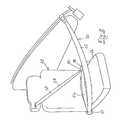
- FIGS. 1-3diagrammatically illustrate a seat belt system 20 utilizing the present invention.
- FIG. 1illustrates a seat 22 having a seat back 24 , seat cushion 26 and headrest 28 .
- a seat belt retractor 40is integrated within the seat 22 . As illustrated, the retractor is associated with the headrest 28 , however, the retractor could have been situated within the seat back or even the seat cushion; the alternate configuration is shown in FIG. 4 .
- the movable member or anchor 70is slidable within or along a track or rail 100 that is situated within or near the roof rail of the vehicle and may extend through to the forward or A-pillar of the vehicle.
- the roof railis generally shown by numeral 102 and the A-pillar by numeral 102 a (both in phantom line). Further, by way of illustration the vehicle window and door are shown by numerals 102 b and 104 .
- the track or railcan be configured in the outer periphery of the door 104 that is adjacent seat 22 .
- U.S. Pat. Nos. 4,242,471; 4,741,555; 4,230,342 and 4,193,613show passive motorized seat belt systems some of which show the track in the roof rail while others show the track in the door rail. Each of these patents is incorporated herein by reference.
- Various seat belt bucklessuch as 82 include some type of electrical or electronic switch 82 b (shown schematically in FIG. 3 ), which is useful in generating a signal indicative of the fact the tongue 80 has been locked in the buckle 82 .
- These switches 82 bcan be satisfied by reed switches, Hall effect switches, optical switches, etc.
- the present system 20uses this locked seat belt signal to activate motor 110 , thereby causing the member 70 to move a transport mechanism 101 associated with the motor and the rail (or track) to move the member or anchor 70 from its unused or stowed position, generally at end 112 a of rail 100 toward its active or used position at or near end 112 b of rail 100 .
- Any of the transport mechanisms and rails shown in the above-referenced patentscan be used with the present invention.
- the four anchor points of the seat belt system 20are defined by the retractor 40 , the movable member or anchor 70 when it is at end 112 b of the rail, the fixed web guide 60 , and the combination of the tongue/buckle 80 / 82 .
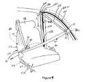
- the retractor 40When the seat belt 50 is in the position illustrated in FIG. 3 and oriented about the occupant, the retractor 40 , and in particular the rewind spring (not shown) of the retractor, will create a bias force on segment 120 , causing the seat belt to slide through the tongue 80 , and through the web guide 60 to tighten the webbing 50 about the seated occupant.
- One of the benefits of the present inventionis that an occupant need not re-learn how to use this present 4-point seat belt system 20 in comparison to conventional 3-point seat belt systems.
- the occupantneed only secure one element of the system, such as a tongue to a single buckle and in so doing automatically forms the lap belt portion 56 of the seat belt and one of the shoulder belt portions 120 .
- the second shoulder belt 122is defined as the system automatically repositions the movable member 70 toward the appropriate end of the rail 100 .
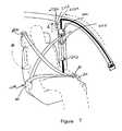
- FIGS. 4 and 5,illustrate an alternate seat system 220 using the present invention.
- System 220also makes use of the translating anchor point, which includes member 70 a translating within a rail or track 100 .
- the track 100includes a first segment 100 a located in the roof rail or in the door rail (which generally corresponds with the rail or track shown in FIGS. 1-3.
- the track or rail 100includes a downward segment 100 b . This downward segment will be located in an adjacent pillar such as the B-pillar 230 . If the rail is located in the door then the downward segment 230 is located in the vertical frame of the door rearward of the window.
- the rail 100includes a transitional portion 100 c between sections 100 a and 100 b.
- the translating member 70 a shown in FIG. 4differs from member 70 of FIG. 1 in that member 70 a includes a web guide portion 72 having a web receiving opening 71 . (With member 70 , the seat belt terminated in the member 70 .) In this alternate embodiment the seat belt webbing 50 is slidably received within opening 71 of the translating web guide 72 . The seat belt webbing extends from the translating web guide 72 to another web guide 240 , which also includes an opening 241 . The webbing extends through web guide 240 and is operatively received onto a spool of another seat belt retractor 250 . The rewind spring of the retractor will tend to wind the webbing on its associated spool.
- the seat belt web guide 240is positioned adjacent the top of the downward segment 100 b of the track 100 .
- the web guide 240is translatable along the rail or track segment 100 a .
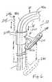
- FIG. 6,shows the web guide 240 in greater detail.
- the web guide 240is part of an assembly 260 , which includes a sleeve 242 slidingly received about the vertical portion 100 b of the rail 100 .
- a bias spring 244upwardly biases the sleeve 242 . More particularly, one end 244 a of spring 244 is connected to the vehicle while another end 244 b is connected to the sleeve 244 .
- the web guide 240extends from the sleeve 244 .
- the seat belt 50is shown in phantom line extending through the slot of the web guide 240 .
- the shape of the web guidemay vary with its application.
- the web guide slot 241 in FIG. 6is oval and in FIGS. 4 and 5 it is more arcuately shaped.
- the web guidecan be rigidly mounted to the sleeve or can be pivoted relative to the sleeve.
- web guide 240is spring loaded, by spring 244 toward the upper end of rail segment 100 b .
- the member 70 aWhen the occupant sits upon the seat, as illustrated in FIG. 5, and manually inserts the tongue 80 into the buckle 82 , the member 70 a , including the web guide 72 , is caused to move along the track segment 100 a , through the transition portion 100 c and thereafter along down segment 100 b of the track.
- the member 70When the member 70 is moved into rail segment 100 b , it forcibly pushes (see arrow 70 ′ in FIG. 6) the spring-loaded web guide (D-ring) 240 down this rail segment 100 b to the lower position also shown in FIG. 5 (in phantom line).
- the motor 110moves the member 70 a and its web guide 72 into the active position whereby the web guide 72 defines one of the anchor points of system 220 as shown in FIG. 5 (although depending on the relative geometry, web guide 240 may act as the anchor point as it may be reacted on by the seat belt).
- Another anchor pointis defined at the buckle 82 while still another is located at web guide 60 .
- the seat belt retractor 250is another anchor point.
- the present inventioncombines a translating anchor point with a 3-point seat belt system to achieve a 4-point seat belt system using a single loop of webbing.
- the first retractor 40is mounted in the seat generally on the inboard side of the seat and can exit the seat at or about the shoulder height of an occupant.
- One end of the single length or loop of the seat belt 50is secured to the first retractor 40 while the opposite end of the seat belt 50 is secured to the second seat belt retractor 250 (in the alternate embodiment of the invention).
- the first or the second retractor 40 or 250can be an electrically controllable retractor.
- a height adjusteris a manual or automatic mechanism that permits the shoulder level web guide to be adjusted upwardly or downwardly to accommodate occupants of different sizes. Moving the web guide up and down permits the occupant to control the angle by which the seat belt (seat belt segment) exits the web guide so as to avoid the situation in which this seat belt segment uncomfortably crosses the occupant's neck.
- the movable anchor 70 acan be stopped at different positions or heights (h) 272 a , 272 b , 272 n along the vertical rail segment 100 b as a function of the size of the occupant.
- the size of the occupantcan be estimated by incorporating an electronic sensor 274 in or along the seat track 276 .
- the taller occupantwill position the seat 22 more rearward and the shorter occupant will position the seat more forward.
- the movable anchor 70 acan be stopped at any of the positions 272 a - 272 n .
- the system 20may include a series of micro-switches embedded in the B-pillar adjacent the rail segment 100 b at the locations 272 a - 272 n.
- a corresponding micro-switchWhen a corresponding micro-switch is activated by interaction with the movable anchor 70 a (as the movable anchor moves within the track 100 b ) continued movement of the moveable anchor is halted.
- the anchor 70 a and hence the web guide 72will be positioned at a location of the activated micro-switch, which in turn corresponds to or is correlatable with the size of the occupant.
- Various other occupant classification sensorsincluding sonar or infrared based sensors can be used to determine occupant size and then accordingly adjust the location of the movable web guide to a comfortable position for that size occupant.
Landscapes
- Engineering & Computer Science (AREA)
- Mechanical Engineering (AREA)
- Automotive Seat Belt Assembly (AREA)
Abstract
Description
Claims (13)
Priority Applications (2)
| Application Number | Priority Date | Filing Date | Title |
|---|---|---|---|
| US10/224,082US6786510B2 (en) | 2002-08-20 | 2002-08-20 | Single loop, four-point shoulder and lap belt system |
| US11/981,971US8464784B2 (en) | 1998-11-20 | 2007-10-31 | Method and system for accessing subterranean deposits from the surface and tools therefor |
Applications Claiming Priority (1)
| Application Number | Priority Date | Filing Date | Title |
|---|---|---|---|
| US10/224,082US6786510B2 (en) | 2002-08-20 | 2002-08-20 | Single loop, four-point shoulder and lap belt system |
Related Parent Applications (1)
| Application Number | Title | Priority Date | Filing Date |
|---|---|---|---|
| US09/769,098Continuation-In-PartUS6598686B1 (en) | 1998-11-20 | 2001-01-24 | Method and system for enhanced access to a subterranean zone |
Related Child Applications (2)
| Application Number | Title | Priority Date | Filing Date |
|---|---|---|---|
| US10/264,535Continuation-In-PartUS6988548B2 (en) | 1998-11-20 | 2002-10-03 | Method and system for removing fluid from a subterranean zone using an enlarged cavity |
| US10/630,345Continuation-In-PartUS8297377B2 (en) | 1998-11-20 | 2003-07-29 | Method and system for accessing subterranean deposits from the surface and tools therefor |
Publications (2)
| Publication Number | Publication Date |
|---|---|
| US20040036270A1 US20040036270A1 (en) | 2004-02-26 |
| US6786510B2true US6786510B2 (en) | 2004-09-07 |
Family
ID=31886746
Family Applications (1)
| Application Number | Title | Priority Date | Filing Date |
|---|---|---|---|
| US10/224,082Expired - Fee RelatedUS6786510B2 (en) | 1998-11-20 | 2002-08-20 | Single loop, four-point shoulder and lap belt system |
Country Status (1)
| Country | Link |
|---|---|
| US (1) | US6786510B2 (en) |
Cited By (26)
| Publication number | Priority date | Publication date | Assignee | Title |
|---|---|---|---|---|
| US20040160051A1 (en)* | 2003-02-14 | 2004-08-19 | Ching-Shan Cheng | Four-point seat restraint |
| US20050121897A1 (en)* | 2003-12-04 | 2005-06-09 | Takata Seat Belts, Inc. | Configurable vehicle restraint system having variable anchor points |
| US20070246927A1 (en)* | 2006-04-21 | 2007-10-25 | Toyota Jidosha Kabushiki Kaisha | Seatbelt device and vehicle |
| US20090115180A1 (en)* | 2007-11-05 | 2009-05-07 | Kabushiki Kaisha Tokai-Rika-Denki-Seisakusho | Seat belt apparatus |
| USD655223S1 (en) | 2010-09-15 | 2012-03-06 | Amsafe Commercial Products, Inc. | Buckle assembly |
| USD661619S1 (en) | 2010-09-15 | 2012-06-12 | Amsafe Commercial Products, Inc. | Buckle assembly |
| US8303043B2 (en) | 2008-09-29 | 2012-11-06 | Amsafe, Inc. (Phoenix Group) | Tensioning apparatuses for occupant restraint systems and associated systems and methods |
| US8327513B2 (en) | 2005-06-09 | 2012-12-11 | Amsafe, Inc. | Buckle assembly having single release for multiple belt connectors |
| US8393645B2 (en) | 2009-11-02 | 2013-03-12 | Amsafe Commercial Products, Inc. | Devices for adjusting tension in seat belts and other restraint system webs, and associated methods |
| US8627554B1 (en) | 2010-05-03 | 2014-01-14 | Amsafe, Inc. (Phoenix Group) | Buckle assemblies with swivel and dual release features and associated methods of use and manufacture |
| US8683666B2 (en) | 2009-11-04 | 2014-04-01 | Amsafe Commercial Products, Inc. | Restraint system buckle components having tactile surfaces, and associated methods of use and manufacture |
| US8777323B2 (en) | 2010-07-20 | 2014-07-15 | Amsafe, Inc. | Restraint harnesses and associated methods of use and manufacture |
| US8820789B2 (en) | 2009-02-23 | 2014-09-02 | Amsafe, Inc. | Seat harness pretensioner |
| US9022483B2 (en) | 2012-06-07 | 2015-05-05 | Shield Restraint Systems, Inc. | Seatbelt buckle tongue assembly |
| US9119445B2 (en) | 2013-02-19 | 2015-09-01 | Amsafe, Inc. | Buckle assemblies with lift latches and associated methods and systems |
| US9277788B2 (en) | 2013-02-19 | 2016-03-08 | Amsafe, Inc. | Dual release buckle assemblies and associated systems and methods |
| US9775410B2 (en) | 2014-12-16 | 2017-10-03 | Shield Restraint Systems, Inc. | Web adjusters for use with restraint systems and associated methods of use and manufacture |
| US9809193B2 (en)* | 2016-03-16 | 2017-11-07 | Shield Restraint Systems, Inc. | Shock absorbing height adjusters for restraint systems and associated systems and methods |
| US9814282B2 (en) | 2016-02-02 | 2017-11-14 | Shield Restraint Systems, Inc. | Harsh environment buckle assemblies and associated systems and methods |
| US20180236967A1 (en)* | 2017-02-21 | 2018-08-23 | Ford Global Technologies, Llc | Seatbelt assembly including a two-point seatbelt |
| US10604259B2 (en) | 2016-01-20 | 2020-03-31 | Amsafe, Inc. | Occupant restraint systems having extending restraints, and associated systems and methods |
| US10611334B2 (en) | 2017-02-07 | 2020-04-07 | Shield Restraint Systems, Inc. | Web adjuster |
| US10953847B2 (en) | 2018-03-06 | 2021-03-23 | Shield Restraint Systems | Height adjusters with anti-cinch features for occupant restraint systems |
| US11273790B2 (en) | 2018-03-06 | 2022-03-15 | Shield Restraint Systems, Inc. | Height adjusters with anti-cinch features for occupant restraint systems |
| US11447093B1 (en) | 2021-08-25 | 2022-09-20 | Ford Global Technologies, Llc | Safety belt D-ring positioning |
| US12280735B2 (en) | 2021-08-25 | 2025-04-22 | Ford Global Technologies, Llc | Safety belt D-ring positioning for front and rear seats |
Families Citing this family (11)
| Publication number | Priority date | Publication date | Assignee | Title |
|---|---|---|---|---|
| JP2007137177A (en)* | 2005-11-16 | 2007-06-07 | Toyota Motor Corp | Seat belt device |
| US7635167B2 (en)* | 2006-08-30 | 2009-12-22 | Honda Motor Co., Ltd | Seat belt shoulder anchor |
| ES2577135T3 (en)* | 2014-01-30 | 2016-07-13 | Brusa Koltuk Ve Ic Trim Teknolojileri Sanayi Ve Tiaret A.S. | Passenger seat for vehicles |
| US10035513B2 (en) | 2015-04-24 | 2018-07-31 | Ford Global Technologies, Llc | Seat belt height system and method |
| US9434349B1 (en)* | 2015-04-24 | 2016-09-06 | Ford Global Technologies, Llc | Seat belt height adjuster system and method |
| JP6233363B2 (en)* | 2015-07-28 | 2017-11-22 | トヨタ自動車株式会社 | 4-point seat belt device. |
| US10150446B2 (en) | 2016-04-11 | 2018-12-11 | Ford Global Technologies, Llc | Belt assembly including payout measurement |
| US10000186B2 (en) | 2016-04-11 | 2018-06-19 | Ford Global Technologies, Llc | Belt assembly including plus-two-point belt reminder |
| US10384639B2 (en)* | 2016-09-23 | 2019-08-20 | Ford Global Technologies, Llc | Plus-two belt reminder system |
| KR102552094B1 (en)* | 2018-12-05 | 2023-07-06 | 현대자동차주식회사 | Advanced Four Point Fixation Type Seat Belt and Vehicle Thereby |
| US20230036452A1 (en)* | 2021-07-28 | 2023-02-02 | Safe, Inc. | Dual three-point restraint system |
Citations (5)
| Publication number | Priority date | Publication date | Assignee | Title |
|---|---|---|---|---|
| US4345780A (en)* | 1979-07-04 | 1982-08-24 | Toyota Jidosha Kogyo Kabushiki Kaisha | Automatic seatbelt system |
| JPH05139245A (en)* | 1991-11-20 | 1993-06-08 | Nissan Motor Co Ltd | Vehiculr seat belt device |
| US5443577A (en)* | 1993-12-10 | 1995-08-22 | Kim; Jong K. | Automatically put-on automobile safety belt |
| US6042190A (en)* | 1997-09-19 | 2000-03-28 | Daimlerchrysler Ag | Vehicle seat |
| US6325417B1 (en)* | 1995-12-29 | 2001-12-04 | Ab Volvo | Arrangement for safety-belt |
- 2002
- 2002-08-20USUS10/224,082patent/US6786510B2/ennot_activeExpired - Fee Related
Patent Citations (5)
| Publication number | Priority date | Publication date | Assignee | Title |
|---|---|---|---|---|
| US4345780A (en)* | 1979-07-04 | 1982-08-24 | Toyota Jidosha Kogyo Kabushiki Kaisha | Automatic seatbelt system |
| JPH05139245A (en)* | 1991-11-20 | 1993-06-08 | Nissan Motor Co Ltd | Vehiculr seat belt device |
| US5443577A (en)* | 1993-12-10 | 1995-08-22 | Kim; Jong K. | Automatically put-on automobile safety belt |
| US6325417B1 (en)* | 1995-12-29 | 2001-12-04 | Ab Volvo | Arrangement for safety-belt |
| US6042190A (en)* | 1997-09-19 | 2000-03-28 | Daimlerchrysler Ag | Vehicle seat |
Cited By (34)
| Publication number | Priority date | Publication date | Assignee | Title |
|---|---|---|---|---|
| US20040160051A1 (en)* | 2003-02-14 | 2004-08-19 | Ching-Shan Cheng | Four-point seat restraint |
| US6869105B2 (en)* | 2003-02-14 | 2005-03-22 | General Motors Corporation | Four-point seat restraint |
| US20050121897A1 (en)* | 2003-12-04 | 2005-06-09 | Takata Seat Belts, Inc. | Configurable vehicle restraint system having variable anchor points |
| US7364199B2 (en)* | 2003-12-04 | 2008-04-29 | Takata Seat Belts, Inc. | Configurable vehicle restraint system having variable anchor points |
| US8567022B2 (en) | 2005-06-09 | 2013-10-29 | Amsafe, Inc. | Buckle assembly having single release for multiple belt connectors |
| US8327513B2 (en) | 2005-06-09 | 2012-12-11 | Amsafe, Inc. | Buckle assembly having single release for multiple belt connectors |
| JP2007290423A (en)* | 2006-04-21 | 2007-11-08 | Toyota Motor Corp | Seat belt device |
| US20070246927A1 (en)* | 2006-04-21 | 2007-10-25 | Toyota Jidosha Kabushiki Kaisha | Seatbelt device and vehicle |
| US7938447B2 (en)* | 2007-11-05 | 2011-05-10 | Kabushiki Kaisha Tokai-Rika-Denki-Seisakusho | Seat belt apparatus |
| US20090115180A1 (en)* | 2007-11-05 | 2009-05-07 | Kabushiki Kaisha Tokai-Rika-Denki-Seisakusho | Seat belt apparatus |
| US8303043B2 (en) | 2008-09-29 | 2012-11-06 | Amsafe, Inc. (Phoenix Group) | Tensioning apparatuses for occupant restraint systems and associated systems and methods |
| US8632131B2 (en) | 2008-09-29 | 2014-01-21 | Amsafe, Inc. | Tensioning apparatuses for occupant restraint systems and associated systems and methods |
| US8820789B2 (en) | 2009-02-23 | 2014-09-02 | Amsafe, Inc. | Seat harness pretensioner |
| US8393645B2 (en) | 2009-11-02 | 2013-03-12 | Amsafe Commercial Products, Inc. | Devices for adjusting tension in seat belts and other restraint system webs, and associated methods |
| US8683666B2 (en) | 2009-11-04 | 2014-04-01 | Amsafe Commercial Products, Inc. | Restraint system buckle components having tactile surfaces, and associated methods of use and manufacture |
| US8627554B1 (en) | 2010-05-03 | 2014-01-14 | Amsafe, Inc. (Phoenix Group) | Buckle assemblies with swivel and dual release features and associated methods of use and manufacture |
| US8777323B2 (en) | 2010-07-20 | 2014-07-15 | Amsafe, Inc. | Restraint harnesses and associated methods of use and manufacture |
| USD655223S1 (en) | 2010-09-15 | 2012-03-06 | Amsafe Commercial Products, Inc. | Buckle assembly |
| USD661619S1 (en) | 2010-09-15 | 2012-06-12 | Amsafe Commercial Products, Inc. | Buckle assembly |
| US9022483B2 (en) | 2012-06-07 | 2015-05-05 | Shield Restraint Systems, Inc. | Seatbelt buckle tongue assembly |
| US9119445B2 (en) | 2013-02-19 | 2015-09-01 | Amsafe, Inc. | Buckle assemblies with lift latches and associated methods and systems |
| US9277788B2 (en) | 2013-02-19 | 2016-03-08 | Amsafe, Inc. | Dual release buckle assemblies and associated systems and methods |
| US9775410B2 (en) | 2014-12-16 | 2017-10-03 | Shield Restraint Systems, Inc. | Web adjusters for use with restraint systems and associated methods of use and manufacture |
| US10604259B2 (en) | 2016-01-20 | 2020-03-31 | Amsafe, Inc. | Occupant restraint systems having extending restraints, and associated systems and methods |
| US9814282B2 (en) | 2016-02-02 | 2017-11-14 | Shield Restraint Systems, Inc. | Harsh environment buckle assemblies and associated systems and methods |
| US9809193B2 (en)* | 2016-03-16 | 2017-11-07 | Shield Restraint Systems, Inc. | Shock absorbing height adjusters for restraint systems and associated systems and methods |
| US10611334B2 (en) | 2017-02-07 | 2020-04-07 | Shield Restraint Systems, Inc. | Web adjuster |
| CN108454559A (en)* | 2017-02-21 | 2018-08-28 | 福特全球技术公司 | Safety belt assembly including two-point belt |
| US20180236967A1 (en)* | 2017-02-21 | 2018-08-23 | Ford Global Technologies, Llc | Seatbelt assembly including a two-point seatbelt |
| US10703329B2 (en) | 2017-02-21 | 2020-07-07 | Ford Global Technologies, Llc | Seatbelt assembly including a two-point seatbelt |
| US10953847B2 (en) | 2018-03-06 | 2021-03-23 | Shield Restraint Systems | Height adjusters with anti-cinch features for occupant restraint systems |
| US11273790B2 (en) | 2018-03-06 | 2022-03-15 | Shield Restraint Systems, Inc. | Height adjusters with anti-cinch features for occupant restraint systems |
| US11447093B1 (en) | 2021-08-25 | 2022-09-20 | Ford Global Technologies, Llc | Safety belt D-ring positioning |
| US12280735B2 (en) | 2021-08-25 | 2025-04-22 | Ford Global Technologies, Llc | Safety belt D-ring positioning for front and rear seats |
Also Published As
| Publication number | Publication date |
|---|---|
| US20040036270A1 (en) | 2004-02-26 |
Similar Documents
| Publication | Publication Date | Title |
|---|---|---|
| US6786510B2 (en) | Single loop, four-point shoulder and lap belt system | |
| US6769716B2 (en) | Seat belt restraint system with movable lap belt guides | |
| US7703806B2 (en) | Seat belt system for a motor vehicle | |
| US4738485A (en) | Seat assembly with occupant restraint system | |
| US5609367A (en) | Adjustable three-point restraint seat belt system for children and adults | |
| US7571934B2 (en) | Seat belt system for adults and children | |
| US3860261A (en) | Vehicle safety belt system | |
| US7118133B2 (en) | Seat belt pretensioner | |
| US6116696A (en) | Interlocking detachable seat belt system | |
| US20080100051A1 (en) | Seat belt arrangement for child occupants of a vehicle | |
| US6267409B1 (en) | Vehicle restraint presenting system | |
| EP1783014B1 (en) | Restraint system for a motor vehicle | |
| US7147251B2 (en) | Seat belt pretensioner | |
| JP3454790B2 (en) | Multi-point pretensioner system | |
| US7806439B2 (en) | Active anti-bunching D-ring seat belt system | |
| EP0868329A2 (en) | Arrangement for safety-belt | |
| WO1996040542A1 (en) | Automobile armrest apparatus for presenting restraint system | |
| US6193275B1 (en) | Occupant belt presenter | |
| US10384570B2 (en) | Child-seat restraint system | |
| US7367630B2 (en) | Integrated seat of an automotive vehicle | |
| US6508500B2 (en) | Integrated seat belt and seat support | |
| US6869104B2 (en) | Motorized adjustment of seat belt anchor position | |
| JP2010143372A (en) | Occupant restraint device for vehicle | |
| US4220355A (en) | Cam guide for passive shoulder harness | |
| CA2574586C (en) | Seat belt pretensioner |
Legal Events
| Date | Code | Title | Description |
|---|---|---|---|
| AS | Assignment | Owner name:BREED AUTOMOTIVE TECHNOLOGY, INC., FLORIDA Free format text:ASSIGNMENT OF ASSIGNORS INTEREST;ASSIGNORS:ROYCHOUDHURY, RAJ S.;KEMPF, PETER C.;KONING, RICHARD W.;REEL/FRAME:013218/0256 Effective date:20020820 | |
| AS | Assignment | Owner name:CITICORP USA, INC. AS "ADMINISTRATOVE AGENT" AND C Free format text:SECURITY AGREEMENT;ASSIGNOR:BREED TECHNOLOGIES, INC.;REEL/FRAME:014409/0767 Effective date:20030425 | |
| AS | Assignment | Owner name:KEY SAFETY SYSTEMS, INC., MICHIGAN Free format text:ASSIGNMENT OF ASSIGNORS INTEREST;ASSIGNOR:BREED AUTOMOTIVE TECHNOLOGY INC.;REEL/FRAME:015016/0229 Effective date:20040224 | |
| AS | Assignment | Owner name:CITICORP USA, INC., NEW YORK Free format text:SECURITY AGREEMENT;ASSIGNORS:KEY SAFETY SYSTEMS, INC;KSS HOLDINGS, INC;KSS ACQUISITION COMPANY;AND OTHERS;REEL/FRAME:019297/0249 Effective date:20070308 Owner name:CITICORP USA, INC.,NEW YORK Free format text:SECURITY AGREEMENT;ASSIGNORS:KEY SAFETY SYSTEMS, INC;KSS HOLDINGS, INC;KSS ACQUISITION COMPANY;AND OTHERS;REEL/FRAME:019297/0249 Effective date:20070308 | |
| REMI | Maintenance fee reminder mailed | ||
| LAPS | Lapse for failure to pay maintenance fees | ||
| LAPS | Lapse for failure to pay maintenance fees | Free format text:PATENT EXPIRED FOR FAILURE TO PAY MAINTENANCE FEES (ORIGINAL EVENT CODE: EXP.); ENTITY STATUS OF PATENT OWNER: LARGE ENTITY | |
| STCH | Information on status: patent discontinuation | Free format text:PATENT EXPIRED DUE TO NONPAYMENT OF MAINTENANCE FEES UNDER 37 CFR 1.362 | |
| FP | Lapsed due to failure to pay maintenance fee | Effective date:20080907 | |
| FEPP | Fee payment procedure | Free format text:PAYOR NUMBER ASSIGNED (ORIGINAL EVENT CODE: ASPN); ENTITY STATUS OF PATENT OWNER: LARGE ENTITY |