US6786217B2 - Method and apparatus of delivery of inhaled nitric oxide to spontaneous-breathing and mechanically-ventilated patients - Google Patents
Method and apparatus of delivery of inhaled nitric oxide to spontaneous-breathing and mechanically-ventilated patientsDownload PDFInfo
- Publication number
- US6786217B2 US6786217B2US10/348,238US34823803AUS6786217B2US 6786217 B2US6786217 B2US 6786217B2US 34823803 AUS34823803 AUS 34823803AUS 6786217 B2US6786217 B2US 6786217B2
- Authority
- US
- United States
- Prior art keywords
- containing gas
- inspiration
- oxygen
- flow
- patient
- Prior art date
- Legal status (The legal status is an assumption and is not a legal conclusion. Google has not performed a legal analysis and makes no representation as to the accuracy of the status listed.)
- Expired - Lifetime
Links
- 238000000034methodMethods0.000titleclaimsabstractdescription68
- MWUXSHHQAYIFBG-UHFFFAOYSA-NNitric oxideChemical compoundO=[N]MWUXSHHQAYIFBG-UHFFFAOYSA-N0.000titleclaimsdescription236
- 238000012384transportation and deliveryMethods0.000titleclaimsdescription74
- 239000007789gasSubstances0.000claimsabstractdescription535
- 229910052760oxygenInorganic materials0.000claimsabstractdescription277
- 239000001301oxygenSubstances0.000claimsabstractdescription277
- QVGXLLKOCUKJST-UHFFFAOYSA-Natomic oxygenChemical compound[O]QVGXLLKOCUKJST-UHFFFAOYSA-N0.000claimsabstractdescription270
- 230000029058respiratory gaseous exchangeEffects0.000claimsdescription30
- 238000010926purgeMethods0.000claimsdescription23
- 230000007423decreaseEffects0.000claimsdescription19
- 239000000203mixtureSubstances0.000claimsdescription10
- 230000004044responseEffects0.000claimsdescription10
- 238000012544monitoring processMethods0.000claimsdescription4
- 238000001514detection methodMethods0.000claimsdescription2
- MGWGWNFMUOTEHG-UHFFFAOYSA-N4-(3,5-dimethylphenyl)-1,3-thiazol-2-amineChemical compoundCC1=CC(C)=CC(C=2N=C(N)SC=2)=C1MGWGWNFMUOTEHG-UHFFFAOYSA-N0.000claims3
- JCXJVPUVTGWSNB-UHFFFAOYSA-Nnitrogen dioxideInorganic materialsO=[N]=OJCXJVPUVTGWSNB-UHFFFAOYSA-N0.000claims3
- 210000004072lungAnatomy0.000description14
- 230000003434inspiratory effectEffects0.000description7
- 238000002156mixingMethods0.000description6
- 230000000241respiratory effectEffects0.000description6
- 238000009423ventilationMethods0.000description6
- 238000006243chemical reactionMethods0.000description5
- 230000003247decreasing effectEffects0.000description5
- 238000002716delivery methodMethods0.000description5
- 208000002815pulmonary hypertensionDiseases0.000description5
- 231100000331toxicToxicity0.000description5
- 230000002588toxic effectEffects0.000description5
- IJGRMHOSHXDMSA-UHFFFAOYSA-NAtomic nitrogenChemical compoundN#NIJGRMHOSHXDMSA-UHFFFAOYSA-N0.000description4
- 208000006673asthmaDiseases0.000description4
- 201000010099diseaseDiseases0.000description4
- 208000037265diseases, disorders, signs and symptomsDiseases0.000description4
- 229940079593drugDrugs0.000description4
- 239000003814drugSubstances0.000description4
- 230000009885systemic effectEffects0.000description4
- 229940124549vasodilatorDrugs0.000description4
- 239000003071vasodilator agentSubstances0.000description4
- 210000003038endotheliumAnatomy0.000description3
- 239000011261inert gasSubstances0.000description3
- 238000002347injectionMethods0.000description3
- 239000007924injectionSubstances0.000description3
- 238000005259measurementMethods0.000description3
- 238000005399mechanical ventilationMethods0.000description3
- 230000007246mechanismEffects0.000description3
- 208000023504respiratory system diseaseDiseases0.000description3
- 238000003860storageMethods0.000description3
- 238000011144upstream manufacturingMethods0.000description3
- 206010001052Acute respiratory distress syndromeDiseases0.000description2
- 208000013616Respiratory Distress SyndromeDiseases0.000description2
- 208000011341adult acute respiratory distress syndromeDiseases0.000description2
- 201000000028adult respiratory distress syndromeDiseases0.000description2
- 230000008901benefitEffects0.000description2
- 238000010276constructionMethods0.000description2
- 229910001882dioxygenInorganic materials0.000description2
- 238000002664inhalation therapyMethods0.000description2
- 238000012986modificationMethods0.000description2
- 230000004048modificationEffects0.000description2
- 229910052757nitrogenInorganic materials0.000description2
- 210000001147pulmonary arteryAnatomy0.000description2
- 230000036387respiratory rateEffects0.000description2
- 210000002345respiratory systemAnatomy0.000description2
- 230000002269spontaneous effectEffects0.000description2
- 238000002627tracheal intubationMethods0.000description2
- 230000003519ventilatory effectEffects0.000description2
- 206010006458Bronchitis chronicDiseases0.000description1
- 206010006482BronchospasmDiseases0.000description1
- 229940127291Calcium channel antagonistDrugs0.000description1
- 206010007559Cardiac failure congestiveDiseases0.000description1
- 208000006545Chronic Obstructive Pulmonary DiseaseDiseases0.000description1
- MYMOFIZGZYHOMD-UHFFFAOYSA-NDioxygenChemical compoundO=OMYMOFIZGZYHOMD-UHFFFAOYSA-N0.000description1
- 206010014561EmphysemaDiseases0.000description1
- 206010019280Heart failuresDiseases0.000description1
- 108010054147HemoglobinsProteins0.000description1
- 102000001554HemoglobinsHuman genes0.000description1
- 208000035202High altitude pulmonary edemaDiseases0.000description1
- 208000019693Lung diseaseDiseases0.000description1
- 108010061951MethemoglobinProteins0.000description1
- 206010063837Reperfusion injuryDiseases0.000description1
- 206010040070Septic ShockDiseases0.000description1
- 230000009471actionEffects0.000description1
- 230000004872arterial blood pressureEffects0.000description1
- YEESUBCSWGVPCE-UHFFFAOYSA-Nazanylidyneoxidanium iron(2+) pentacyanideChemical compound[Fe++].[C-]#N.[C-]#N.[C-]#N.[C-]#N.[C-]#N.N#[O+]YEESUBCSWGVPCE-UHFFFAOYSA-N0.000description1
- 230000009286beneficial effectEffects0.000description1
- 239000008280bloodSubstances0.000description1
- 210000004369bloodAnatomy0.000description1
- 230000036772blood pressureEffects0.000description1
- 210000004204blood vesselAnatomy0.000description1
- 206010006451bronchitisDiseases0.000description1
- 230000007885bronchoconstrictionEffects0.000description1
- 239000006227byproductSubstances0.000description1
- 239000000480calcium channel blockerSubstances0.000description1
- 230000015556catabolic processEffects0.000description1
- 239000003795chemical substances by applicationSubstances0.000description1
- 208000007451chronic bronchitisDiseases0.000description1
- 238000002485combustion reactionMethods0.000description1
- 229940124446critical care medicineDrugs0.000description1
- 238000006731degradation reactionMethods0.000description1
- 230000001419dependent effectEffects0.000description1
- 239000003344environmental pollutantSubstances0.000description1
- 229960001123epoprostenolDrugs0.000description1
- KAQKFAOMNZTLHT-VVUHWYTRSA-NepoprostenolChemical compoundO1C(=CCCCC(O)=O)C[C@@H]2[C@@H](/C=C/[C@@H](O)CCCCC)[C@H](O)C[C@@H]21KAQKFAOMNZTLHT-VVUHWYTRSA-N0.000description1
- 239000008246gaseous mixtureSubstances0.000description1
- 231100001261hazardousToxicity0.000description1
- 230000036541healthEffects0.000description1
- -1hydroalazineSubstances0.000description1
- 208000012947ischemia reperfusion injuryDiseases0.000description1
- 238000004519manufacturing processMethods0.000description1
- 239000000463materialSubstances0.000description1
- 229960002460nitroprussideDrugs0.000description1
- 230000003647oxidationEffects0.000description1
- 238000007254oxidation reactionMethods0.000description1
- 230000002265preventionEffects0.000description1
- 230000008569processEffects0.000description1
- 230000002685pulmonary effectEffects0.000description1
- 230000036593pulmonary vascular resistanceEffects0.000description1
- 239000002516radical scavengerSubstances0.000description1
- 230000036303septic shockEffects0.000description1
- 230000000153supplemental effectEffects0.000description1
- 230000001360synchronised effectEffects0.000description1
- 238000002054transplantationMethods0.000description1
- 239000006163transport mediaSubstances0.000description1
- 238000013022ventingMethods0.000description1
Images


Classifications
- A—HUMAN NECESSITIES
- A61—MEDICAL OR VETERINARY SCIENCE; HYGIENE
- A61M—DEVICES FOR INTRODUCING MEDIA INTO, OR ONTO, THE BODY; DEVICES FOR TRANSDUCING BODY MEDIA OR FOR TAKING MEDIA FROM THE BODY; DEVICES FOR PRODUCING OR ENDING SLEEP OR STUPOR
- A61M16/00—Devices for influencing the respiratory system of patients by gas treatment, e.g. ventilators; Tracheal tubes
- A61M16/10—Preparation of respiratory gases or vapours
- A61M16/12—Preparation of respiratory gases or vapours by mixing different gases
- A—HUMAN NECESSITIES
- A61—MEDICAL OR VETERINARY SCIENCE; HYGIENE
- A61M—DEVICES FOR INTRODUCING MEDIA INTO, OR ONTO, THE BODY; DEVICES FOR TRANSDUCING BODY MEDIA OR FOR TAKING MEDIA FROM THE BODY; DEVICES FOR PRODUCING OR ENDING SLEEP OR STUPOR
- A61M16/00—Devices for influencing the respiratory system of patients by gas treatment, e.g. ventilators; Tracheal tubes
- A61M16/10—Preparation of respiratory gases or vapours
- A61M16/1005—Preparation of respiratory gases or vapours with O2 features or with parameter measurement
- A61M16/1015—Preparation of respiratory gases or vapours with O2 features or with parameter measurement using a gas flush valve, e.g. oxygen flush valve
- A—HUMAN NECESSITIES
- A61—MEDICAL OR VETERINARY SCIENCE; HYGIENE
- A61M—DEVICES FOR INTRODUCING MEDIA INTO, OR ONTO, THE BODY; DEVICES FOR TRANSDUCING BODY MEDIA OR FOR TAKING MEDIA FROM THE BODY; DEVICES FOR PRODUCING OR ENDING SLEEP OR STUPOR
- A61M16/00—Devices for influencing the respiratory system of patients by gas treatment, e.g. ventilators; Tracheal tubes
- A61M16/20—Valves specially adapted to medical respiratory devices
- A61M16/201—Controlled valves
- A61M16/202—Controlled valves electrically actuated
- A61M16/203—Proportional
- A61M16/204—Proportional used for inhalation control
- A—HUMAN NECESSITIES
- A61—MEDICAL OR VETERINARY SCIENCE; HYGIENE
- A61M—DEVICES FOR INTRODUCING MEDIA INTO, OR ONTO, THE BODY; DEVICES FOR TRANSDUCING BODY MEDIA OR FOR TAKING MEDIA FROM THE BODY; DEVICES FOR PRODUCING OR ENDING SLEEP OR STUPOR
- A61M16/00—Devices for influencing the respiratory system of patients by gas treatment, e.g. ventilators; Tracheal tubes
- A61M16/08—Bellows; Connecting tubes ; Water traps; Patient circuits
- A61M16/0816—Joints or connectors
- A61M16/0833—T- or Y-type connectors, e.g. Y-piece
- A—HUMAN NECESSITIES
- A61—MEDICAL OR VETERINARY SCIENCE; HYGIENE
- A61M—DEVICES FOR INTRODUCING MEDIA INTO, OR ONTO, THE BODY; DEVICES FOR TRANSDUCING BODY MEDIA OR FOR TAKING MEDIA FROM THE BODY; DEVICES FOR PRODUCING OR ENDING SLEEP OR STUPOR
- A61M16/00—Devices for influencing the respiratory system of patients by gas treatment, e.g. ventilators; Tracheal tubes
- A61M16/10—Preparation of respiratory gases or vapours
- A61M16/1005—Preparation of respiratory gases or vapours with O2 features or with parameter measurement
- A61M2016/102—Measuring a parameter of the content of the delivered gas
- A61M2016/1025—Measuring a parameter of the content of the delivered gas the O2 concentration
- A—HUMAN NECESSITIES
- A61—MEDICAL OR VETERINARY SCIENCE; HYGIENE
- A61M—DEVICES FOR INTRODUCING MEDIA INTO, OR ONTO, THE BODY; DEVICES FOR TRANSDUCING BODY MEDIA OR FOR TAKING MEDIA FROM THE BODY; DEVICES FOR PRODUCING OR ENDING SLEEP OR STUPOR
- A61M2202/00—Special media to be introduced, removed or treated
- A61M2202/02—Gases
- A61M2202/0266—Nitrogen (N)
- A61M2202/0275—Nitric oxide [NO]
Definitions
- the inventiongenerally relates to an apparatus and method for measurement, mixing, monitoring, and delivery of gases to a patient, including nitric oxide (“NO”) and oxygen. More specifically, the invention relates to an apparatus and method of delivering gaseous NO to spontaneous-breathing patients as well as to patients connected to a mechanical ventilator.
- NOnitric oxide
- oxygenMore specifically, the invention relates to an apparatus and method of delivering gaseous NO to spontaneous-breathing patients as well as to patients connected to a mechanical ventilator.
- NOis an environmental pollutant produced as a byproduct of combustion. At high concentrations (generally at or above 1000 ppm), NO is toxic. NO also is a naturally occurring gas that is produced by the endothelium tissue of the respiratory system. In the 1980's, it was discovered by researchers that the endothelium tissue of the human body produced NO, and that NO is an endogenous vasodilator, namely, an agent that widens the internal diameter of blood vessels.
- inhaled NOhas been found to decrease pulmonary artery pressure (PAP) as well as pulmonary vascular resistance (PVR).
- PAPpulmonary artery pressure
- PVRpulmonary vascular resistance
- pulmonary hypertensionwas treated by the administration of drugs known as systemic vasodilators.
- systemic vasodilatorssuch as prostacyclin, nitroprusside, hydroalazine, and calcium channel blockers suffered from the limitation that the drugs, by their nature, produced systemic effects. For example, the drugs not only decreased PAP levels, but also systemic blood pressure.
- inhaled NOacts as a selective pulmonary vasodilator, acting primarily on the endothelium tissue of the lung. Upon inhalation, NO is absorbed into the capillary blood in the precapillary airspaces and alveolar capillaries. Inhaled NO has negligible action beyond the site of its uptake since NO is rapidly inactivated by the reaction with hemoglobin to form methemoglobin.
- NOhas been investigated for the treatment of patients with increased airway resistance as a result of emphysema, chronic bronchitis, asthma, adult respiratory distress syndrome (ARDS), and chronic obstructive pulmonary disease, (COPD).
- NO inhalation therapyis thought to be beneficial include, by way of illustration and not by way of limitation: allograft lung transplantation, ischemia-reperfusion injury, congestive heart failure, septic shock, and high-altitude pulmonary edema.
- NOhas shown promising preliminary results with respect to the treatment and prevention of the diseases mentioned above, delivery methods and devices must cope with certain problems inherent with gaseous NO delivery.
- OSHAOccupational Safety and Health Administration
- NOis administrated to patients in the concentration range of about 1 ppm to about 100 ppm.
- NOrapidly oxidizes in the presence of oxygen to form NO 2 , which is highly toxic, even at low levels.
- OSHAhas set exposure limits for NO 2 at 5 ppm.
- NO 2is highly toxic, even at low levels.
- OSHAhas set exposure limits for NO 2 at 5 ppm.
- the rate of oxidation of NO to NO 2is dependent on numerous factors, including the concentration of NO, the concentration of O 2 , and the time available for reaction.
- One problem with the inhalation of NOis that when NO is therapeutically inhaled, it is often mixed with high concentrations of O 2 . Consequently, this increases the conversion rate of NO to NO 2 . It is thus preferable to minimize the contact time between NO and O 2 when the NO is combined with a source of oxygen gas.
- the '433 patentdiscloses a method and apparatus for supplying NO to a patient. According to the '433 patent, a very short pulse of NO is delivered intermittently, either at the start or end of inspiration.
- the '433 patentthus teaches the delivery of a bolus or plug of nitric oxide to the patient by administering a very short pulse of NO during inspiration. The timing of the delivery (beginning vs. late) is altered depending on the disease that is to be treated.
- the pulses of NO delivered according to the '433 patentare of a predetermined width, which can be altered by changing the amount of time that a control valve is left open.
- the '433 patentfails to disclose the proportional delivery of NO gas to the patient having a flow profile that tracks or is proportional or quasi-proportional to the flow profile of an oxygen-containing gas.
- the valve mechanismprovides a bolus, or square wave-type “plug” of NO to the patient, the length of which, is altered by adjusting its width (i.e., holding the valve in the open position for a longer period of time).
- the pulsehas the flow profile of a square wave regardless of the profile of the patient's inspiration profile.
- NOis administered to patients that are either spontaneously breathing or connected to a mechanical ventilator.
- a patienttypically wears a tight fitting mask, transtracheal O 2 catheter, nasal cannula, or other tubing passing directly into the airway of a patient.
- NOis typically mixed with O 2 and air prior to introduction into the patient airway. See Dean Hess, Ph.D., et al., “ Delivery Systems for Inhaled Nitric Oxide ,” Respiratory Care Clinics of North America, Vol. 3, No. 3, pp. 402-404 Sep. 1997.
- These spontaneous systemssuffer from the limitation that the NO concentration can fluctuate within a relatively wide range.
- the dose of NOvaries with the patient's ventilatory pattern due to the fact that the patient's inspiration profile changes on a breath-by-breath basis. The delivered dose of NO is thus approximated from assumptions regarding the patient's ventilatory pattern.
- the NO/N 2 streamis premixed with Air/O 2 prior to entering the ventilator. While such pre-mixing may better permit the inspired concentration of NO to be controlled, the production of NO 2 is significantly higher given the longer contact time between NO and O 2 . This is particularly true for ventilators with large internal volumes.
- NOis continuously injected into the inspiratory limb of the ventilator circuit.
- This methodhas difficulty maintaining a stable NO concentration throughout the entire inspiration flow.
- the inspiratory circuitfills with NO during expiration, and a large bolus of NO is delivered to the patient in the next breath. See, e.g. Dean Hess, Ph.D., et al., “ Delivery Systems for Inhaled Nitric Oxide ,” Respiratory Care Clinics of North America, Vol. 3, No. 3, p. 381 Sep. 1997.
- This methodmay result in an inspired NO concentration that may be more than double the calculated or estimated dose.
- the concentration of delivered NOvaries with the length of the patient's expiration. For example, when the expiratory time is short, the delivered NO concentration is lower due to less time for filling the inspiratory limb with NO.
- Yet another method of delivering NOinvolves intermittent injections of an NO-containing gas into the patient's inspiratory limb.
- NOis delivered into the inspiratory limb only during the inspiratory phase.
- the flow from the ventilatormust be continuously and precisely measured, and the injected does of NO must be precisely titrated such that the delivered NO and inspiratory flow waveform are not affected. See, Dean Hess, Ph.D., et al., “ Delivery Systems for Inhaled Nitric Oxide ,” Respiratory Care Clinics of North America, Vol. 3, No. 3, p. 384, Sep. 1997.
- I-NOvent Delivery System(Ohmeda).
- I-NOvent Delivery Systema device separate and apart from the mechanical ventilator injects NO directly into the inspiration circuit of the patient. Flow in the inspiration limb of the circuit is measured via a flow sensor and NO is injected in proportion to the measured flow to provide the desired dose. See, Dean Hess, Ph.D., et al., “ Delivery Systems for Inhaled Nitric Oxide ,” Respiratory Care Clinics of North America, Vol. 3, No. 3, p. 395, Sep. 1997.
- NOdomo deviceAnother commercial device utilizing intermittent injection of NO is the NOdomo device (Dragerwerk, Germany).
- the NOdomo deviceinterfaces, like the I-NOvent Delivery System, with a separate mechanical ventilator. NO addition is controlled via a mass flow controller, adding a proportion of NO into the breathing circuit. Unlike the I-NOvent Delivery System, however, the NOdomo device controls NO flow delivery from an electronic flow controller that receives an input signal directly from the ventilator. See, Dean Hess, Ph.D., et al., “ Delivery Systems for Inhaled Nitric Oxide ,” Respiratory Care Clinics of North America, Vol. 3, No. 3, p. 399 Sep. 1997.
- U.S. Pat. No. 5,558,083 issued to Bathe et al.discloses a NO delivery system.
- the delivery systemcan be used with a mechanical ventilator as well as a gas proportioning device for spontaneous-breathing.
- a CPUcontrols a proportional control valve that is in-line with a source of NO gas.
- the CPUcalculates the desired flow from, among other things, the flow of breathing gas measured via a flow sensor 46 and NO concentration measured by NO sensor 65 .
- the proportional control valve 24 is controlledis to arrive at the desired NO concentration.
- a supplemental supply of O 2 74is connected to the NO line.
- a proportional control valve 78is positioned in-line with the O 2 supply 74 and reports to the CPU 56 .
- the O 2is provided as a safety measure should the O 2 level fall below a critical level. Col. 8 , lines 50 - 61 .
- the CPU 56directs the proportional flow controller to increase the flow of O 2 to the NO/N 2 stream.
- the '083 patentfails to teach or suggest the proportional-type control of NO/N 2 , or O 2 to track or match the flow of either O 2 or the inspiration-profile of a patient. Rather, the O 2 is used as a safety measure should the O 2 concentration fall below a threshold value. Moreover, in the devices disclosed in the '083 and '433 patents, residual NO gas is left in the device/inspiration limb between breaths.
- the devicepreferably can provide either a constant concentration of NO to the patient during inspiration or a non-constant concentration of NO to the patient depending on the desired setting.
- the devicepreferably does not suffer from the limitation of other delivery systems, where NO may remain in the system between breaths. Namely, the device and method preferably eliminates any bolus or residue of NO-containing gas that might build-up between breaths.
- a method of delivering a steady concentration of NO to a spontaneously breathing, patient via delivery meansincludes the step of detecting the onset of inspiration by the patient.
- the inspiration flow profileis determined for an individual breath.
- An oxygen-containing gasis supplied to the delivery means, wherein the oxygen-containing gas has a flow profile that tracks the inspiration flow profile.
- a NO-containing gasis supplied to the delivery means, wherein the NO-containing gas has a flow profile that is proportionally less than the flow profile of the oxygen-containing gas throughout inspiration.
- a method of delivering a non-constant concentration of nitric oxide to a spontaneously breathing patient via delivery meansincludes the steps of the first aspect, however, the NO-containing gas is supplied to the delivery means wherein the NO-containing gas has a flow profile that is less than, but closely tracks the oxygen-containing gas flow profile at the beginning of inspiration, and wherein the difference between the flow profile of the oxygen-containing gas and the flow profile of the nitric oxide-containing gas progressively increases through the remainder of inspiration.
- a third, separate aspect of the inventionanother method of delivering a non-constant concentration of nitric oxide to a spontaneously breathing patient via delivery means is disclosed.
- the methodincludes the steps of the first aspect, however, the nitric oxide-containing gas has a flow profile that is substantially less than the oxygen-containing gas flow profile at the beginning of inspiration compared to the end of inspiration, and wherein the difference between the flow profile of the oxygen-containing gas and the flow profile of the nitric oxide-containing gas progressively decreases throughout the remainder of inspiration.
- a method of delivering a constant concentration of nitric oxide to a mechanically-ventilated patient via single controlleris disclosed.
- the desired inspiration flow profileis set in the controller.
- the flow rate of an oxygen-containing gasis varied in accordance with the inspiration flow profile by delivering a first signal from said controller to a first control valve controlling the rate of flow of an oxygen-containing gas to the patient, thereby creating a flow profile of oxygen-containing gas.
- the flow rate of a nitric oxide-containing gasis varied in accordance with the inspiration profile by delivering a second signal from said controller to a second control valve controlling the rate of flow of the nitric oxide-containing gas to the patient, creating a flow profile of nitric oxide-containing gas.
- the nitric oxide-containing flow profileis less than and proportional to the flow profile of the oxygen-containing gas throughout patient inspiration.
- a method of delivering a non-constant concentration of NO to a mechanically-ventilated patientincludes the steps of the previously recited method, however, the flow rate of the nitric oxide-containing gas is varied to create a flow profile of nitric oxide-containing gas that is less than, but closely tracks the oxygen-containing gas flow profile in the beginning of the inspiration, wherein the difference between the flow profiles of the oxygen-containing gas and the nitric oxide-containing gas progressively increases through the remainder of inspiration.
- the flow rate of the nitric oxide-containing gashas a flow profile that is substantially less than the oxygen-containing gas flow profile at the beginning of inspiration, and wherein the difference between the flow profile of the oxygen-containing gas and the nitric oxide-containing gas progressively decreases throughout the remainder of inspiration.
- a method of delivering nitric oxide via delivery means to a mechanically or spontaneously breathing patient having a certain inspiration profileincludes the aspect of an air flush to eliminate remaining nitric oxide or enriched oxygen.
- the methodincludes the step of supplying in a first breath a mixture of oxygen-containing gas and a nitric oxide-containing gas to the delivery means, the oxygen-containing gas and a nitric oxide-containing gas having a flow profile proportional or quasi proportional to the inspiration flow profile.
- a source of enriched oxygen-containing gasis supplied having a flow profile that is proportional or quasi-proportional to the inspiration flow profile.
- a source of airis supplied at or near the end of the first and next breaths to flush the delivery means of enriched oxygen and nitric oxide.
- a method of delivering nitric oxide to a spontaneously breathing patient via delivery meansincludes the step of detecting the onset of inspiration.
- An oxygen-containing gasis supplied to the delivery means, wherein the oxygen-containing gas has a pre-programmed flow profile.
- a nitric oxide-containing gasis supplied to the delivery means, wherein the nitric oxide-containing gas has a pre-programmed flow profile that is proportional or quasi-proportional to the flow profile of the oxygen-containing gas throughout inspiration.
- a device for delivering nitric oxide to a spontaneous-breathing patientincludes a source of an oxygen-containing gas connected via tubing to a patient inspiration interface device.
- a source of a nitric oxide-containing gasis connected via tubing to the patient inspiration interface device.
- a first proportional flow controlleris located between the source of oxygen-containing gas and the patient inspiration interface device for varying the flow rate of the oxygen-containing gas to the patient inspiration interface device.
- a second proportional flow controlleris located between the source of nitric oxide-containing gas and the patient inspiration interface device for varying the flow rate of the nitric oxide-containing gas to the patient inspiration interface device.
- An inspiration flow profile sensoris provided for detecting the onset of inspiration of the patient.
- the deviceincludes a controller for controlling the first and second proportional flow controllers in response to the detection of the onset of inspiration from the inspiration flow profile sensor, the first and second proportional flow controllers being controlled such that the nitric oxide-containing gas has pre-programmed flow profile that is proportional or quasi-proportional to the flow profile of the oxygen-containing gas throughout inspiration.
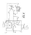
- FIG. 1is a schematic illustration of the device being used with a patient supported by mechanical ventilation.
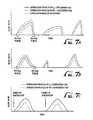
- FIG. 2 ( a )illustrates a square-shaped inspiration profile of the oxygen-containing gas and the NO-containing gas for delivering a constant concentration of NO to a patient.
- FIG. 2 ( b )illustrates a sine-shaped inspiration profile of the oxygen-containing gas and the NO-containing gas for delivering a constant concentration of NO to a patient.
- FIG. 2 ( c )illustrates a ramp-shaped inspiration profile of the oxygen-containing gas and the NO-containing gas for delivering a constant concentration of NO to a patient.
- FIG. 3 ( a )illustrates the inspiration profile of the oxygen-containing gas and the NO-containing gas for delivering a non-constant concentration of NO to a patient, wherein the concentration of NO is higher at the beginning of inspiration than at the end of inspiration.
- FIG. 3 ( b )illustrates the inspiration profiles of the oxygen-containing gas and the NO-containing gas for delivering a non-constant concentration of NO to a patient, wherein the concentration of NO is higher at the end of inspiration than at the beginning of inspiration.
- FIG. 4 ( a )is a flow profile of oxygen-containing gas and NO-containing gas where enriched-oxygen is delivered between breaths.
- FIG. 4 ( b )shows the flow profile of the oxygen-containing gas, the NO-containing gas, and the air flush according to one aspect of the invention.
- FIG. 5is a schematic illustration of a device being used with a patient supported by mechanical ventilation wherein the air flush aspect is utilized.
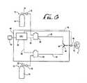
- FIG. 6is a schematic illustration of the device being used with a spontaneously breathing patient.
- FIG. 7 ( a )illustrates a inspiration profile for a spontaneously breathing patient in addition to the flow profiles of the oxygen-containing gas and the NO-containing gas for delivering a constant concentration of NO to a patient.
- FIG. 7 ( b )illustrates another inspiration profile for a spontaneously breathing patient in addition to the flow profiles of the oxygen-containing gas and the NO-containing gas for delivering a constant concentration of NO to a patient.
- FIG. 7 ( c )illustrates pre-programmed inspiration profiles of the oxygen-containing gas and the NO-containing gas.
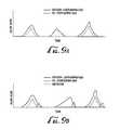
- FIG. 8 ( a )illustrates an inspiration profile for the oxygen-containing gas and the NO-containing gas for delivering a non-constant concentration of NO to a patient, wherein the concentration of NO is higher at the beginning of inspiration than at the end of inspiration.
- FIG. 8 ( b )illustrates another inspiration profile for the oxygen-containing gas and the NO-containing gas for delivering a non-constant concentration of NO to a patient, wherein the concentration of NO is higher at the end of inspiration than at the beginning of; inspiration.
- FIG. 9 ( a )is a flow profile of oxygen-containing gas and NO-containing gas where enriched-oxygen is delivered between breaths.
- FIG. 9 ( b )shows the flow profile of the oxygen-containing gas, the NO-containing gas, and the air flush according to one aspect of the invention.
- FIG. 10is a schematic illustration of a device being used with a spontaneously-breathing patient wherein the air flush aspect is utilized.
- FIG. 1shows a schematic representation of the device 2 for delivering NO gas to a patient 4 connected to a mechanical ventilator 6 .
- the device 2is the mechanical ventilator 6 since both control of patient inspiration, expiration, and delivery of NO are all controlled by the device 2 .
- a separate NO administration deviceis not needed since the device 2 /mechanical ventilator 6 delivers to NO gas to the patient 4 .
- the device 2includes an inspiration limb 8 and an expiration limb 10 .
- the inspiration limb 8 and the expiration limb 10are connected via a Y-piece 12 .
- the Y-piece 12connects to delivery means for delivering the gaseous mixture to the patient 4 .
- the delivery meanspreferably includes a patient inspiration interface device 14 .
- the patient inspiration interface device 14can be any number of devices that connect a generally hollow, tubular construction (i.e., flexible tubing) to the respiratory tract of the patient 4 .
- the patient inspiration interface device 14can include a tube for intubation into the patient's 4 airway, a nasal cannula, a face mask, or a transtracheal catheter.
- the expiration limb 10returns to the device 2 where the expired gases pass through an exhaust port 16 .
- the expired gascan be vented to directly to the atmosphere, or alternatively, the expired gas can pass through an optional gas scavenger system 18 to remove NO and NO 2 from the expiration, gas prior to atmospheric venting.
- the inspiration limb 8is attached to the other end of the Y-piece 12 and serves as a transport medium for the sources of oxygen-containing gas 20 and NO-containing gas 22 to the patient 4 .
- the source of oxygen-containing gas 20can come from any number of sources, including, for example, atmospheric air, compressed air, compressed air enriched with oxygen, and a mixture of oxygen and N 2 .
- the main requirement for the oxygen-containing gas 20is that the gas contain at least some component of oxygen.
- the oxygen-containing gas 20is delivered to the device via a dedicated line in a medical facility having a pre-set oxygen concentration.
- the oxygen-containing gas 20can be delivered via a pressurized cylinder.
- the source of NO-containing gas 22is shown in FIG. 1 as being a pressurized cylinder 24 containing NO gas. While the use of a pressurized cylinder 24 is the preferable method of storing the NO-containing gas 22 , other storage and delivery means, such as a dedicated feed line (wall supply), can also be used. Typically, the NO-containing gas 22 is a mixture of N 2 and NO. While N 2 is typically used to dilute the concentration of NO, any inert gas can also be used. When the NO-containing gas 22 is stored in pressurized cylinder 24 , it is preferable that the concentration of NO in the pressurized cylinder 24 fall within the range of about 800 ppm to about 1200 ppm.
- nitric oxide manufacturerstypically produce nitric oxide mixtures for medical use at around the 1000 ppm range. Extremely high concentrations of NO are undesirable because accidental leakage of NO gas is more hazardous, and high partial pressures of NO tends to cause the spontaneous degradation of NO into nitrogen.
- Pressurized cylinders 24 with low concentrations of NOare also not as desirable from an economic standpoint. Since a smaller quantity of NO is contained within pressured cylinders 24 having low NO concentrations (i.e., 100 ppm), these pressurized cylinders 24 exhaust their supply of NO much more quickly than a pressurized cylinder 24 containing a higher concentration of NO. Consequently, low NO ppm pressurized cylinders 24 are changed more frequently than pressurized cylinders 24 having a larger concentration of NO. This increases the overall cost of the NO treatment.
- a pressure regulator 26is preferably employed to reduce the pressure of the NO-containing gas 22 prior to introduction to the ventilator 4 .
- the device 2further includes a first control valve 30 that is located in-line between the oxygen-containing gas 20 and the inspiration limb 8 .
- the first control valve 30thus receives the oxygen-containing gas 20 at an input port and modulates, or controls the flow of the oxygen-containing gas 20 into the inspiration limb 8 through a second export port.
- the first control valve 30can include, for example, a proportional control valve that opens (or closes) in a progressively increasing (or decreasing if closing) manner depending on an electronic input.
- the first control valve 30can also include a mass flow controller.
- the first control valve 30can include any number of control valves that can quickly and accurately alter the flow rate of a gas across a relatively wide range of flow rates.
- the output of the first control valve 30leads to the inspiration limb 8 of the patient 4 .
- the first control valve 30controls the inspiration profile of the oxygen-containing gas 20 .
- the inspiration profile of the oxygen-containing gas 20is the flow rate of the oxygen-containing gas 20 as a function of inspiration time.
- the inspiration profile of the oxygen-containing gas 20can be seen in FIG. 2 ( a ).
- a second control valve 32is located in-line between the NO-containing gas 22 and the inspiration limb 8 .
- the second control valve 32thus receives the NO-containing gas 22 at an input port and modulates, or controls the flow of the NO-containing gas 22 into the inspiration limb 8 through a second export port.
- the second control valve 32can include, for example, a proportional control valve that opens (or closes) in a progressively increasing (or decreasing if closing) manner depending on an electronic input.
- the second control valve 32can also include a mass flow controller.
- the second control valve 32can include any number of control valves that can quickly and accurately alter the flow rate of a gas across a relatively wide range of flow rates.
- the inspiration profile of the second control valve 32controls the inspiration profile of the NO-containing gas 22 .
- the inspiration profile of the NO-containing gas 22is the flow rate of the NO-containing gas 22 as a function of time.
- Exiting the second control valve 32is a NO-addition line 34 that enters the inspiration limb 8 .
- the NO-addition line 34thus carries the controlled flow of NO-containing gas 22 to the inspiration limb 8 .
- the NO-addition line 34can enter the inspiration limb 8 at any point between the ventilator 6 and the patient inspiration interface device 14 .
- the NO-addition line 34enters the inspiration limb 8 at a location that is prior to the Y-piece 12 .
- the NO-addition line 34preferably enters the inspiration limb 8 upstream of the location where the gas concentration measurements are made. Even more preferably, the NO-addition line 34 enters the inspiration limb 8 upstream of where the gas concentration measurements are made at a distance that is equal to, or greater than, six-times the internal diameter of the tubing used in the inspiration limb 8 .
- the devicefurther includes CPU 36 .
- the CPU 36acts as a controller of the first and second control valves 30 , 32 .
- the CPU 36sends, via signal lines 38 , 40 , signals to control the opening and closing of the control valves 30 , 32 .
- the CPU 36contains preset instructions on controlling the inspiration profiles of the oxygen-containing gas 20 and the NO-containing gas 22 .
- the instructionscan be stored in read-only-memory (ROM) on the CPU 36 , or alternatively, the instructions can be input to the CPU 36 via an input device 42 .
- the input device 42can be any number of devices that encode the flow profiles of the oxygen-containing gas 20 and the NO-containing gas 22 . These include, by way of illustration, and not by way of limitation: a computer, a diskette, a control panel, and the like.
- the input device 42can input, for example, the set-point concentration of NO in the breathing gas.
- the desired set-point concentration of NOis typically set by a physician, for example.
- the input device 42can thus alter the degree of proportionality between the flow profile of the oxygen-containing gas 20 and the flow profile of the NO-containing gas 22 .
- a higher degree of proportionalityi.e., the flow profile of the NO-containing gas 22 more closely tracks the flow profile of the oxygen-containing gas 20
- the degree of proportionalityalso affects the timing of the NO gas purge.
- the input device 42may also input gas purge parameters to the CPU 36 to determine when the flow profile of the NO-containing gas 22 is truncated. This can be done, for example, by establishing a time after inspiration is started at which the flow profile of the NO-containing gas 22 is dropped to zero. Alternatively, the NO-containing gas 22 can terminate once the flow rate of the oxygen-containing gas 20 drops below a certain pre-set level. These-settings can be input to the CPU 36 via the input device 42 .
- the CPU 36controls the inspiration flow profile of each breath of the patient.
- the CPU 36can create any number of inspiration-flow profiles.
- the CPU 36can deliver a sine-shaped, square-shaped, or ramp-shaped inspiration flow profile.
- inspiration flow profilesother than those specifically mentioned-above can also be delivered to the patient 4 .
- the CPU 36can also control other parameters such as the respiratory rate, tidal volume, and inspiration pressure settings. These parameters can be sent to the CPU 36 via input device 42 .
- the present inventioncontemplates using a CPU 36 that gives the device 2 complete programmability.
- the flow profiles of the both the oxygen-containing gas 20 and the NO-containing gas 22can be controlled during a single breath. While proportional and quasi-proportional flow profiles are disclosed in greater detail herein, it should be appreciated that any flow profile (of the oxygen-containing gas 20 or the NO-containing gas 22 ) can be produced for a single breath of a patient 4 . Complete programmability is also possible where the device employs input device 42 .
- CPU 36is shown as the preferred controller for controlling the flow profiles of the oxygen-containing gas 20 and the NO-containing gas 22 , the present invention further contemplates using an analog switching mechanism (not shown) as an alternative controller.
- the device 2delivers to a patient 4 a preset tidal volume at a predetermined respiratory rate.
- the inspiration flow profile that is desirede.g., sine, square, or ramp
- FIGS. 2 ( a )- 2 ( b )show the flow profiles of the oxygen-containing and NO-containing gases 20 , 22 .
- the flow profile of the NO-containing gas 22is proportional to the flow profile of the oxygen-containing gas 20 .
- Proportionalis meant to indicate that the flow rate of the NO-containing gas 22 is less than, but proportionally tracks the flow profile of the oxygen-containing gas 20 throughout the patient's inspiration (the exception to this being the optional truncation of NO flow as described more fully below).
- the delivered gas mixture of NO and oxygenhas near constant concentration. The patient 4 thus receives a steady concentration of NO throughout inspiration.
- the proportional flowis accomplished via the single CPU 36 .
- the CPU 36sends signals to the first and second controller valves 30 , 32 to keep the flow of the NO-containing gas 22 lower, but in proportion to the flow of the oxygen-containing gas 20 . Since a single CPU 36 is used to control both the first and second control valves 30 , 32 , there is no need to measure and report back to a control unit, the flow rate of either the NO-containing gas stream 22 or the oxygen-containing gas stream 20 via a flow sensor or the like.
- the proportional flow controlalso has the benefit of purging the inspiration limb 8 of NO-containing gas 22 during certain inspiration flow patterns. For example, as seen in FIGS. 2 ( b ) & 2 ( c ), the flow rate of the NO-containing gas 22 reaches zero near the end portion of inspiration while the oxygen-containing gas 20 continues to have positive flow. In this regard, the flow of oxygen-containing gas 20 purges the inspiration limb 8 of NO until the next breath.
- the CPU 36can send a close-valve signal to the second control valve 32 near the end of patient inspiration.
- This close-valve signaltruncates the flow profile (the truncated flow profile 52 is shown in FIGS. 2 ( a )-( c )) of the NO-containing gas 22 and leaves the oxygen-containing gas 20 as the only flow.
- the oxygen-containing gas 20thus purges the inspiration limb 8 of NO.
- the CPU 36controls the flow of the NO-containing gas 22 and the oxygen-containing gas 20 to provide for a non-constant concentration of NO in the breathing gas of a patient 4 .
- FIGS. 3 ( a ) & 3 ( b )show the flow profiles of the operation of the device 2 according to this embodiment.
- FIG. 3 ( a )shows a variable concentration delivery mode for NO that provides a higher concentration of NO to the patient 4 during the beginning of inspiration.
- the flow profile of the NO-containing gas 22is less than the flow profile of the oxygen-containing gas 20 .
- the flow profile of the NO-containing gas 22closely tracks the oxygen-containing gas 20 flow profile at the beginning of inspiration (quasi-proportional), but begins to tail-off as inspiration progresses. In this manner, the difference between the flow profiles of the oxygen-containing gas 20 and the NO-containing gas 22 progressively increases through the remainder of inspiration. In this method of delivery, a higher concentration of NO is delivered to the patient 4 at the beginning of inspiration than at the end of inspiration.
- This flow profileis used when it is desirous for NO to be delivered deep within the lungs, for instance, to treat pulmonary hypertension.
- the present methodprovides a gradual gradient of NO in the lungs wherein the concentration of NO in the upper airway is lower than the concentration of NO in the lowermost regions of the lung.
- the flow profile of the NO-containing gas 22more closely matches the flow profile of the oxygen-containing gas 20 .
- the flow profile of the NO-containing gas 22is not a square wave as disclosed in the '433 patent. Rather, the flow profile is quasi-proportional to the oxygen-containing gas 20 profile.
- This methodis advantageous over the method of delivery disclosed in the '433 patent because the bolus delivered in the '433 patent is of such a short length that the targeted area of the lung can be missed entirely.
- the target area of the lungsis bathed in at least some concentration of NO.
- the difference between the flow rate of the oxygen-containing gas 20 and the NO-containing gas 22increases (or decreases as shown in FIG. 3 ( b )) during the time of inspiration, the total amount of NO delivered per breath is smaller when compared to a square wave profile of NO.
- the pressurized cylinder 24 containing the NO-containing gas 22thus needs less frequent changing.
- Another important aspect of this method of deliveryis that the flow profile of the NO-containing gas 22 reaches zero prior to the flow profile of the oxygen-containing gas 20 . See FIGS. 3 ( a ) and 3 ( b ).
- the oxygen-containing gas 20 that continues to flowaids in purging the inspiration limb 8 of NO.
- the difference between the flow profiles of the oxygen-containing gas 20 and the NO-containing gas 22progressively increases through the remainder of inspiration.
- the rate of this increasemay be controlled by the CPU 36 .
- the increasemay be linear, non-linear, exponential, etc., depending on the desired flow profile of the NO-containing gas 22 .
- the rate of this increasemay be set by the input device 42 .
- FIG. 3 ( b )another flow profile is shown for the NO-containing gas 22 that provides for a greater NO concentration at the end of the patient's 4 inspiration profile.
- the flow profile of the NO-containing gas 22is less than the flow profile of the oxygen-containing gas 20 .
- the flow profile of the NO-containing gas 22is substantially less than the oxygen-containing gas 20 at the beginning of inspiration.
- the flow rate of the NO-containing gas 22is zero at the beginning of inspiration, while the flow rate of the oxygen-containing gas 20 is positive.
- inspirationproceeds, the difference between the flow profile of the oxygen-containing gas 20 and the NO-containing gas 22 progressively decreases. In this profile, a higher concentration of NO is delivered to the upper airway region of the lungs. This method is used, for example, in breathing diseases relating to broncho-constriction of the airways, such as asthma.
- the difference between the flow profiles of the oxygen-containing gas 20 and the NO-containing gas 22progressively decreases through the remainder of inspiration.
- the rate of this decreasemay be controlled by the CPU 36 .
- the decreasemay be linear, non-linear, exponential, etc., depending on the desired flow profile of the NO-containing gas 22 .
- the rate of this decreasemay be set by the input device 42 .
- the oxygen-containing gas 20is flowing, but the NO-containing gas 22 is not. Consequently, the flow of the oxygen-containing gas 20 acts to purge the inspiration limb 8 of NO that may have remained from the previous breath.
- a patient 4receives a first inhalation containing both oxygen-containing gas 20 and NO-containing gas 22 .
- the patientreceives just oxygen-containing gas 20 .
- this inspirationcontains a relatively high concentration of oxygen-containing gas 20 (oxygen-enriched).
- the patient 4again receives an oxygen-containing gas 20 and an NO-containing gas 22 .
- the profilecould also include, for example, two or more oxygen-containing gas 22 -only inspirations between inspirations having both oxygen-containing gas 20 and NO-containing gas 22 .
- FIG. 4 ( b )Yet another flow profile is shown in FIG. 4 ( b ).
- a patient 4is delivered, on inspiration, a flow profile including an oxygen-containing gas 20 and a NO-containing gas 22 .
- an air flushis delivered to the patient 4 .
- the air flushserves to remove any NO-containing gas 22 that may be in the inspiration limb 8 .
- an oxygen-containing gas 20is delivered to the patient 4 without any NO-containing gas 22 .
- the oxygen-containing gas 20includes an elevated level of oxygen (enriched-oxygen).
- another air flushis delivered to the patient 4 . This air flush is delivered to the patient 4 and serves to remove any enriched-oxygen remaining in the inspiration limb 8 as well as any residual NO gas.
- the air used to flush the inspiration limb 8while the other source is the enriched-oxygen-containing gas 20 .
- the source of air for the air flushcan be, for example, a separate pressurized cylinder, wall supply, compressor, pump, or the like.
- FIG. 5, for example,shows the air being stored in a pressurized cylinder 25 while the enriched oxygen-containing gas 20 enters the device via a wall supply or the like.
- the flow of airis modulated by a third control valve 33 that is controlled by the CPU 36 via signal line 41 .
- the device 2can use a pressurized cylinder 24 having a relatively high concentration of NO (about 1000 ppm), since the, second flow controller 32 is always controlled to provide a smaller flow rate of NO-containing gas 22 than the flow rate of the oxygen-containing gas 20 .
- the device 2can further include an optional gas monitor 44 .
- the gas monitor 44preferably monitors the concentration of one or more of the following gases in the inspiration limb 8 of the device 2 : oxygen, NO, and NO 2 .
- the gas monitor 44determines the concentration of gas(es) via a sensor(s) 46 located in the inspiration limb 8 .
- the sensor(s) 46can be a chemilluminesence-type, electrochemical cell-type, or spectrophotometric-type sensor 46 based on the accuracy and response time desired.
- the gas monitor 44preferably includes a display screen 48 that illustrates, on a real-time basis or as close to a real-time basis as possible, the concentrations of the measured gases.
- the gas monitor 44preferably reports the gas concentration data to the CPU 36 via signal line 50 .
- the CPU 36can use the real-time concentration data to determine if the NO or NO 2 concentration levels exceed certain predetermined set-points input via input device 42 . For example, if the NO 2 concentration exceeds the set-point concentration, the CPU can send a close-valve signal to the second. control valve 32 . In this regard, the NO-containing gas 22 is shut-off entirely.
- the level of oxygen in the gas streamcan also be monitored via the monitor 44 . If the oxygen concentration drops below a certain concentration, the CPU 36 can decrease the flow of the NO-containing gas 22 and/or increase the flow rate of the oxygen-containing gas 20 .
- the above-described device 2can also be used in modes other than continuous mandatory ventilation.
- the device 2can also-be used with assisted ventilation, synchronized intermittent ventilation (SIMV), intermittent mandatory ventilation (IMV), and pressure support ventilation. Still other modes of operation will also work with the device 2 .
- SIMVsynchronized intermittent ventilation
- IMVintermittent mandatory ventilation
- pressure support ventilationStill other modes of operation will also work with the device 2 .
- a device 60 for a spontaneously breathing patient 4includes an oxygen-containing gas limb 62 and a NO-containing gas limb 64 .
- Both the oxygen-containing gas limb 62 and a NO-containing gas limb 64are preferably made of a hollow, flexible tubing material.
- the oxygen and NO limbs 62 , 64combine at a mixing point 66 .
- the mixing point 66may include a Y-piece 68 that connects with another hollow flexible tube that then travels to the patient 4 .
- the combined gasesenter the patient's airway via delivery means.
- the delivery meanspreferably includes a patient inspiration interface device 70 .
- the patient inspiration interface device 70can include a tube for intubation into the patient's 4 airway, a nasal cannula, a face mask, or transtracheal catheter.
- a source 72 of oxygen-containing gas 20delivers the oxygen-containing gas 20 into the oxygen-containing gas limb 62 .
- the source 72 of oxygen-containing gas 20preferably is a pressurized cylinder 74 .
- the pressurized cylinder 74can contain atmospheric air, compressed air, compressed air mixed with oxygen, or a mixture of oxygen and nitrogen.
- the main requirement for the oxygen source 72is that the gas contain at least some component of oxygen.
- pressurized cylinder 74is the preferable method of storing the oxygen source 72
- other storage meanssuch as a dedicated feed line (wall supply), can also be used.
- the oxygencan be delivered from a compressor or pump.
- the NO source 76is shown as a pressurized cylinder 74 . While the use of a pressurized cylinder 74 is the preferable method of storing the NO-containing gas 22 , other storage and delivery means, such as a dedicated feed line, can also be used. Preferably, the NO-containing gas 22 is a mixture of N 2 and NO. While N 2 is typically used to dilute the concentration of NO, any inert gas can also be used. When the NO-containing gas 22 is stored in pressurized cylinder 74 , it is preferable that the concentration of NO in the cylinder fall within the range of about 800 ppm to about 1200 ppm.
- the NO concentrationfall with the range of about 1 ppm to about 100 ppm.
- a NO source 76at higher concentrations for the same stated reasons for the mechanical ventilator embodiment.
- pressure regulators 78are preferably used to reduce the pressures of the respective gases.
- the device 60includes a first control valve 80 that is located in-line between the source 72 of oxygen-containing gas 20 and the oxygen-containing gas limb 62 . As with the mechanical ventilator device 2 .
- the first control valve 80thus receives the oxygen-containing gas 20 at an input port and modulates, or controls the flow of the oxygen-containing gas 20 into the oxygen-containing gas limb 62 through a second export port.
- the first control valve 80can include, for example, a proportional control valve that opens (or closes) in a progressively increasing (or decreasing if closing) manner depending on an electronic input.
- the first control valve 80can also include a mass flow controller.
- the first control valve 80can include any number of control valves that can quickly and accurately alter the flow rate of a gas across a relatively wide range of flow rates.
- the output of the first control valve 80leads to the oxygen-containing gas limb 62 of the patient 4 .
- the first control valve 80controls the inspiration profile of the oxygen-containing gas 20 .
- the inspiration profile of the oxygen-containing gas 20is the flow rate of the oxygen-containing gas 20 as a function of inspiration time.
- the inspiration profile of the oxygen-containing gas 20can be seen in FIGS. 7 ( a ) and 7 ( b ).
- a second control valve 82is located in-line between the NO-containing gas 22 and the NO-containing gas limb 64 .
- the second control valve 82thus receives the NO-containing gas 22 at an input port and modulates, or controls the flow of the NO-containing gas 22 into the NO-containing gas limb 64 through a second export port.
- the second control valve 82can include, for example, a proportional control valve that opens (or closes) in a progressively increasing (or decreasing if closing) manner depending on an electronic input.
- the second control valve 82can also include a mass flow controller.
- the second control valve 82can include any number of control valves that can quickly and accurately alter the flow rate of a gas across a relatively wide range of flow rates.
- the inspiration profile of the second control valve 82controls the inspiration profile of the NO-containing gas 22 .
- the inspiration profile of the NO-containing gas 22is the flow rate of the NO-containing gas 22 as a function of time.
- the spontaneously breathing device 60includes a CPU 84 .
- the CPU 84controls the first and second control valves 80 , 82 .
- the CPU 84sends, via signal lines 86 , 88 , signals to control the opening and closing of the control valves 80 , 82 .
- the device 60further includes an inspiration flow profile sensor 90 that is positioned in the patient 4 breathing limb.
- the inspiration flow profile sensor 90is located downstream of the mixing point 66 , but upstream of the patient inspiration interface device 70 .
- the inspiration flow profile sensor 90detects the flow rate of the inspired gas by the patient 4 .
- the inspiration flow profile sensor 90thus detects the onset of inspiration as well as the inspiration flow profile throughout the remainder of the breath.
- the flow profile sensor 90can include any number of devices, including venturi-based sensor, hot wire anemometer, rotating vane, thermal flow, pressure transducer, and the like.
- a flow profile sensor 90is used that can rapidly detect small changes in the breathing flow rate over a wide range of flow rates.
- the flow profile sensor 90detects only the onset of inspiration by the patient 4 .
- the inspiration profile sensor 90reports the inspiration flow rate data back to the CPU 84 via signal line 92 on preferably a real-time basis (or as close to a real-time basis as possible).
- the flow rate data reported back to the CPU 84is the flow rate of the breathing gas (oxygen-containing gas 20 and NO-containing gas 22 ) as a function of time. This data represents the inspiration flow profile for each individual breath.
- the inspiration profile sensor 90can just measure the onset of inspiration.
- the data reflecting the onset of inspirationis delivered as a signal to CPU 84 .
- Pre-programmed flow profiles of the oxygen-containing gas 20 and the NO-containing gas 22are then delivered to the patient 4 .
- the pre-programmed flow profiles of the oxygen-containing gas 20 and the NO-containing gas 22are determined by empirical studies of patient inhalation characteristics.
- the flow profile of the oxygen-containing gas 20 and the NO-containing gas 22can be proportional, quasi-proportional, or any other pre-determined flow pattern. This aspect is shown, for example, in FIG. 7 ( c ).
- the CPU 84controls both the first and second control valves 80 , 82 to delivery respective flow profiles of oxygen and NO.
- the CPU 84contains instructions to deliver proportional flows of both the oxygen-containing gas 20 and the NO-containing gas 22 .
- a steady concentration of NOis delivered to the patient.
- This flow patternis embodied in FIGS. 7 ( a ) & 7 ( b ).
- the dotted-line in FIG. 1illustrates the inspiration flow profile of the patient 4 . As can be seen in FIGS.
- the device 60preferably includes an input device 94 .
- the input device 94can be any number of devices including, for example, a computer, diskette, control panel, and the like.
- the input device 94can control, for example, the set-point concentration of NO in the breathing gas.
- the input device 94can thus alter the degree of proportionality between the flow profile of the oxygen-containing gas 20 and the flow profile of the NO-containing gas 22 .
- a higher degree of proportionalityi.e., the flow profile of the NO-containing gas 22 more closely tracks the flow profile of the oxygen-containing gas 20
- the degree of proportionalityalso affects the timing of the NO gas purge.
- the input device 94may also input gas purge parameters to the CPU 84 to determine when the flow profile of the NO-containing gas 22 is truncated. This can be done, for example, by establishing a time after inspiration is started at which the flow profile of the NO-containing gas 22 is dropped to zero. Alternatively, the NO-containing gas 22 d can terminate once the flow rate of the oxygen-containing gas 20 drops below a certain pre-set level. These settings can be input to the CPU 84 via the input device 94 .
- the proportional flow of the NO-containing gas 22also provides the device 60 and method with a purge feature to purge any NO gas from the lines and the patient inspiration interface device 70 .
- a purge featureto purge any NO gas from the lines and the patient inspiration interface device 70 .
- the present inventionalso contemplates using a CPU 84 that gives the device 60 complete programmability.
- the flow profiles of the both the oxygen-containing gas 20 and the NO-containing gas 22can be controlled during a single breath. While proportional and quasi-proportional flow profiles are disclosed in greater detail herein, it should be appreciated that any flow profile (of the oxygen-containing gas 20 or the NO-containing gas 22 ) can be produced for a single breath of a patient 4 . Complete programmability is also possible where the device employs input device 94 .
- CPU 84is shown as the preferred controller for controlling the flow profiles of the oxygen-containing gas 20 and the NO-containing gas 22 , the present invention further contemplates using an analog switching mechanism (not shown) as an alternative controller.
- the device 60can further include an optional gas monitor 96 .
- the gas monitor 96preferably monitors the concentration of one or more of the following gases in the inspiration limb of the device 60 : oxygen, NO, and NO 2 .
- the gas monitor 96determines the concentration of gas(es) via a sensor(s) 98 located in the inspiration limb.
- the sensor(s) 98can be a chemilluminesence-type, electrochemical cell-type, or spectrophotometric-type sensor 98 based on the accuracy and response time desired.
- the gas monitor 96preferably includes a display screen 100 that illustrates, on a real-time basis or as close to a real-time basis as possible, the concentrations of the measured gases.
- a non-constant concentration of NOis delivered to the patient 4 .
- the flow profile of the NO-containing gas 22is such that a higher concentration of NO is delivered at the beginning of inspiration than the concentration delivered near the end of inspiration.
- the flow profile of the NO-containing gas 22is less than flow profile of the oxygen-containing gas 20 and closely tracks the oxygen-containing gas 20 flow profile at the beginning of inspiration (quasi-proportional), but begins to tail-off as inspiration progresses. In this manner, the difference between the flow profiles of the oxygen-containing gas 20 and the NO-containing gas 22 progressively increases through the remainder of inspiration.
- This flow profileis used when it is desirous for NO to be delivered deep within the lungs, for instance, to treat pulmonary hypertension.
- This method of deliveryprovides a gradual gradient of NO through the in the lungs rather than a bolus of NO that is disclosed in the '433 patent.
- the difference between the flow profiles of the oxygen-containing gas 20 and the NO-containing gas 22progressively increases through the remainder of inspiration.
- the rate of this increasemay be controlled by the CPU 84 .
- the increasemay be linear, non-linear, exponential, etc., depending on the desired flow profile of the NO-containing gas 22 .
- the rate of this increasemay be set by the input device 94 .
- This delivery methodalso contains gas purge feature that purges any NO gas from the lines and the patient inspiration interface device 70 .
- gas purge featurethat purges any NO gas from the lines and the patient inspiration interface device 70 .
- the flow of oxygen-containing gas 20purges the system of NO gas.
- FIG. 8 ( b )another flow profile is shown for the NO-containing gas 22 that provides for a greater NO concentration at the end portion of a patient's 4 inspiration.
- the flow profile of the NO-containing gas 22is substantially less than the oxygen-containing gas 20 flow profile.
- the flow profile of the NO-containing gas 22starts out at zero, while the flow profile of the oxygen-containing gas 20 is positive.
- the flow profile of the NO-containing gas 22begins to more closely track the flow profile of the oxygen-containing gas 20 , wherein the difference between the flow profile of the oxygen-containing gas 20 and the NO-containing gas 22 progressively decreases throughout the remainder of inspiration.
- a higher concentration of NOis delivered to the upper airway region of the lungs. This method is used, as stated previously, in breathing diseases relating to broncho-construction of the airways, such as asthma.
- the difference between the flow profiles of the oxygen-containing gas 20 and the NO-containing gas 22progressively decreases through the remainder of inspiration.
- the rate of this decreasemay be controlled by the CPU 84 .
- the decreasemay be linear, non-linear, exponential, etc., depending on the desired flow profile of the NO-containing gas 22 .
- the rate of this decreasemay be set by the input device 94 .
- This delivery methodalso contains gas purge feature that purges any NO gas from the lines and the patient inspiration interface device 70 .
- gas purge featurethat purges any NO gas from the lines and the patient inspiration interface device 70 .
- the flow of oxygen-containing gas 20purges the system of NO gas. Consequently, any remaining NO that might have remained in the lines and/or patient inspiration interface device 70 from the previous breath are purged by the flow of the oxygen-containing gas 20 .
- a patient 4receives a first inhalation containing both oxygen-containing gas 20 and NO-containing gas 22 .
- the patientreceives just oxygen-containing gas 20 .
- this inspirationcontains a relatively high concentration of oxygen-containing gas 20 (oxygen-enriched).
- the patient 4again receives an oxygen-containing gas 20 and an NO-containing gas 22 .
- FIG. 9 ( b )Yet another flow profile is shown in FIG. 9 ( b ).
- a patient 4is delivered, on inspiration, a flow profile including an oxygen-containing gas 20 and a NO-containing gas 22 .
- an air flushis delivered to the patient 4 .
- the air flushserves to remove any NO-containing gas 22 that may be in the inspiration limb 8 .
- an oxygen-containing gas 20is delivered to the patient 4 without any NO-containing gas 22 .
- the oxygen-containing gas 20includes an elevated level of oxygen (enriched-oxygen).
- another air flushis delivered to the patient 4 . This air flush is delivered to the patient 4 and serves to remove any enriched-oxygen gas remaining in the inspiration limb 8 .
- the air used to flush the device 60there are two separate sources of oxygen-containing gas 20 .
- One sourceis the air used to flush the device 60 while the other source is the enriched-oxygen-containing gas 20 .
- the source of air for the air flushcan be, for example, a separate pressurized cylinder, wall supply, compressor, pump, or the like.
- FIG. 10, for example,shows the air being stored in a pressurized cylinder 75 while the enriched oxygen-containing gas 20 enters the device via a wall supply or the like.
- the flow of airis modulated by a third control valve 83 that is controlled by the CPU 84 via signal line 89 .
Landscapes
- Health & Medical Sciences (AREA)
- Emergency Medicine (AREA)
- Pulmonology (AREA)
- Engineering & Computer Science (AREA)
- Anesthesiology (AREA)
- Biomedical Technology (AREA)
- Heart & Thoracic Surgery (AREA)
- Hematology (AREA)
- Life Sciences & Earth Sciences (AREA)
- Animal Behavior & Ethology (AREA)
- General Health & Medical Sciences (AREA)
- Public Health (AREA)
- Veterinary Medicine (AREA)
- Pharmaceuticals Containing Other Organic And Inorganic Compounds (AREA)
Abstract
Description
Claims (33)
Priority Applications (3)
| Application Number | Priority Date | Filing Date | Title |
|---|---|---|---|
| US10/348,238US6786217B2 (en) | 1999-11-24 | 2003-01-21 | Method and apparatus of delivery of inhaled nitric oxide to spontaneous-breathing and mechanically-ventilated patients |
| US10/896,329US20050076907A1 (en) | 1999-11-24 | 2004-07-21 | Method and apparatus for delivery of inhaled nitric oxide to spontaneous-breathing and mechanically-ventilated patients |
| US11/234,849US7516742B2 (en) | 1999-11-24 | 2005-09-23 | Method and apparatus for delivery of inhaled nitric oxide to spontaneous-breathing and mechanically-ventilated patients with intermittent dosing |
Applications Claiming Priority (2)
| Application Number | Priority Date | Filing Date | Title |
|---|---|---|---|
| US09/449,240US6581599B1 (en) | 1999-11-24 | 1999-11-24 | Method and apparatus for delivery of inhaled nitric oxide to spontaneous-breathing and mechanically-ventilated patients |
| US10/348,238US6786217B2 (en) | 1999-11-24 | 2003-01-21 | Method and apparatus of delivery of inhaled nitric oxide to spontaneous-breathing and mechanically-ventilated patients |
Related Parent Applications (1)
| Application Number | Title | Priority Date | Filing Date |
|---|---|---|---|
| US09/449,240ContinuationUS6581599B1 (en) | 1999-11-24 | 1999-11-24 | Method and apparatus for delivery of inhaled nitric oxide to spontaneous-breathing and mechanically-ventilated patients |
Related Child Applications (1)
| Application Number | Title | Priority Date | Filing Date |
|---|---|---|---|
| US10/896,329ContinuationUS20050076907A1 (en) | 1999-11-24 | 2004-07-21 | Method and apparatus for delivery of inhaled nitric oxide to spontaneous-breathing and mechanically-ventilated patients |
Publications (2)
| Publication Number | Publication Date |
|---|---|
| US20030131848A1 US20030131848A1 (en) | 2003-07-17 |
| US6786217B2true US6786217B2 (en) | 2004-09-07 |
Family
ID=23783437
Family Applications (3)
| Application Number | Title | Priority Date | Filing Date |
|---|---|---|---|
| US09/449,240Expired - LifetimeUS6581599B1 (en) | 1999-11-24 | 1999-11-24 | Method and apparatus for delivery of inhaled nitric oxide to spontaneous-breathing and mechanically-ventilated patients |
| US10/348,238Expired - LifetimeUS6786217B2 (en) | 1999-11-24 | 2003-01-21 | Method and apparatus of delivery of inhaled nitric oxide to spontaneous-breathing and mechanically-ventilated patients |
| US10/896,329AbandonedUS20050076907A1 (en) | 1999-11-24 | 2004-07-21 | Method and apparatus for delivery of inhaled nitric oxide to spontaneous-breathing and mechanically-ventilated patients |
Family Applications Before (1)
| Application Number | Title | Priority Date | Filing Date |
|---|---|---|---|
| US09/449,240Expired - LifetimeUS6581599B1 (en) | 1999-11-24 | 1999-11-24 | Method and apparatus for delivery of inhaled nitric oxide to spontaneous-breathing and mechanically-ventilated patients |
Family Applications After (1)
| Application Number | Title | Priority Date | Filing Date |
|---|---|---|---|
| US10/896,329AbandonedUS20050076907A1 (en) | 1999-11-24 | 2004-07-21 | Method and apparatus for delivery of inhaled nitric oxide to spontaneous-breathing and mechanically-ventilated patients |
Country Status (1)
| Country | Link |
|---|---|
| US (3) | US6581599B1 (en) |
Cited By (47)
| Publication number | Priority date | Publication date | Assignee | Title |
|---|---|---|---|---|
| US20020195106A1 (en)* | 2001-06-19 | 2002-12-26 | Mitsuru Uchiyama | Apparatus for supplying a therapeutic oxygen gas |
| US20040060341A1 (en)* | 2002-09-27 | 2004-04-01 | Spx Corporation | Gas analyzer automated purge/zero process |
| US20040168686A1 (en)* | 2003-02-18 | 2004-09-02 | Christian Krebs | Metered administration of a therapeutic gas |
| US20050076907A1 (en)* | 1999-11-24 | 2005-04-14 | Alex Stenzler | Method and apparatus for delivery of inhaled nitric oxide to spontaneous-breathing and mechanically-ventilated patients |
| US6955171B1 (en)* | 2000-10-16 | 2005-10-18 | Pulmonox Technologies Corporation | System and method for delivering therapeutic gas to a patient |
| US20050247311A1 (en)* | 2002-09-16 | 2005-11-10 | Charles Vacchiano | Reduced-oxygen breathing device |
| US20060266355A1 (en)* | 2005-05-24 | 2006-11-30 | Boaz Misholi | Apparatus and method for controlling fraction of inspired oxygen |
| US20070181126A1 (en)* | 2006-02-08 | 2007-08-09 | Tolmie Craig R | Method and apparatus for ventilating a patient with a breathing gas mixture formed from nitric oxide, air, and oxygen |
| US20080000471A1 (en)* | 2003-04-22 | 2008-01-03 | Kenneth Bolam | Mri/nmr-compatible, tidal volume control and measurement systems, methods, and devices for respiratory and hyperpolarized gas delivery |
| US7516742B2 (en) | 1999-11-24 | 2009-04-14 | Cardinal Health 207, Inc. | Method and apparatus for delivery of inhaled nitric oxide to spontaneous-breathing and mechanically-ventilated patients with intermittent dosing |
| US7520866B2 (en) | 2000-12-26 | 2009-04-21 | Sensormedics Corporation | Device and method for treatment of wounds with nitric oxide |
| US7531133B2 (en) | 2002-09-10 | 2009-05-12 | Pulmonox Technologies Corporation | Use of nitric oxide gas in an extracorporeal circuitry to treat blood plasma |
| US20090183737A1 (en)* | 2008-01-22 | 2009-07-23 | The General Electric Company | Pulse width modulated medical gas concentration control |
| US20090291022A1 (en)* | 2008-03-24 | 2009-11-26 | Minton Christian S | Anti-microbial gas apparatus and method |
| US20100003349A1 (en)* | 2002-12-10 | 2010-01-07 | Miller J W Randolph | Portable, nitric oxide generator |
| US20100021506A1 (en)* | 2008-01-31 | 2010-01-28 | Jones Christie M | Nitric oxide gel apparatus and method |
| US20100018526A1 (en)* | 2008-01-31 | 2010-01-28 | Miller Randy J | Nitric oxide reactor and distributor apparatus and method |
| US20100081955A1 (en)* | 2008-09-30 | 2010-04-01 | Nellcor Puritan Bennett Llc | Sampling Circuit for Measuring Analytes |
| US20100186742A1 (en)* | 2009-01-29 | 2010-07-29 | Impact Instrumentation, Inc. | Medical ventilator with autonomous control of oxygenation |
| US7892198B2 (en) | 2000-12-26 | 2011-02-22 | Sensormedics Corporation | Device and method for treatment of surface infections with nitric oxide |
| US7955294B2 (en) | 2004-05-11 | 2011-06-07 | Sensormedics Corporation | Intermittent dosing of nitric oxide gas |
| US8079998B2 (en) | 2006-10-20 | 2011-12-20 | Pulmonox Technologies Corporation | Methods and devices for the delivery of therapeutic gases including nitric oxide |
| US8425428B2 (en) | 2008-03-31 | 2013-04-23 | Covidien Lp | Nitric oxide measurements in patients using flowfeedback |
| US8485183B2 (en) | 2008-06-06 | 2013-07-16 | Covidien Lp | Systems and methods for triggering and cycling a ventilator based on reconstructed patient effort signal |
| US8518457B2 (en) | 2004-05-11 | 2013-08-27 | Pulmonox Technologies Corporation | Use of inhaled gaseous nitric oxide as a mucolytic agent or expectorant |
| US8685467B2 (en) | 2010-08-03 | 2014-04-01 | J. W. Randolph Miller | Nitric oxide generation, dilution, and topical application apparatus and method |
| US8714154B2 (en) | 2011-03-30 | 2014-05-06 | Covidien Lp | Systems and methods for automatic adjustment of ventilator settings |
| US8893717B2 (en) | 2005-09-21 | 2014-11-25 | Ino Therapeutics Llc | Systems and methods of administering a pharmaceutical gas to a patient |
| US20150273175A1 (en)* | 2014-04-01 | 2015-10-01 | Ino Therapeutics Llc | Systems And Method For Delivery Of Therapeutic Gas To Patients In Need Thereof Using Enhanced Breathing Circuit Gas (BCG) Flow Measurement |
| US20150314101A1 (en)* | 2014-05-02 | 2015-11-05 | Ino Therapeutics Llc | Systems and Method for Delivery of Therapeutic Gas to Patients, in Need Thereof, Receiving Breathing Gas From a Ventilator That Varies at Least Pressure and/or Flow Using Enhanced Therapeutic Gas (NO) Flow Measurement |
| US9351994B2 (en) | 2005-09-21 | 2016-05-31 | Mallinckrodt Hospital Products IP Limited | System and method of administering a pharmaceutical gas to a patient |
| US9649467B2 (en) | 2008-01-31 | 2017-05-16 | Syk Technologies, Llc | Nitric oxide reactor and distributor apparatus and method |
| US9808591B2 (en) | 2014-08-15 | 2017-11-07 | Covidien Lp | Methods and systems for breath delivery synchronization |
| US9950129B2 (en) | 2014-10-27 | 2018-04-24 | Covidien Lp | Ventilation triggering using change-point detection |
| US10052348B2 (en) | 2016-01-27 | 2018-08-21 | Syk Technologies, Llc | Nitric oxide topical application apparatus and methods |
| US10362967B2 (en) | 2012-07-09 | 2019-07-30 | Covidien Lp | Systems and methods for missed breath detection and indication |
| US10517817B2 (en) | 2013-05-09 | 2019-12-31 | Syk Technologies, Llc | Deep topical systemic nitric oxide therapy apparatus and method |
| US10758703B2 (en) | 2014-10-17 | 2020-09-01 | Mallinckrodt Hospital Products IP Limited | Systems and methods for providing a pulse of a therapeutic gas with a desired flow profile to maximize therapeutic effectiveness |
| US20210138177A1 (en)* | 2018-01-19 | 2021-05-13 | Ergo-Flex Technologies, LLC | Oxygen Treatment Device for Mammals |
| RU2752856C1 (en)* | 2020-12-28 | 2021-08-11 | Владимир Васильевич Удут | Method for rehabilitation of post-viral injuries of lung parenchyma and device for its implementation |
| WO2021206771A1 (en)* | 2020-04-10 | 2021-10-14 | Jerome Canady Research Institute for Advanced Biological and Technological Sciences | System and method for treatment of respiratory infections and lung cancer with cold atmospheric plasma |
| US11167146B2 (en) | 2020-04-10 | 2021-11-09 | Jerome Canady Research Institute for Advanced Biological and Technological Sciences | System for treatment of respiratory infections and cancers of the respiratory system using cold atmospheric plasma |
| US11369763B2 (en)* | 2020-07-31 | 2022-06-28 | Soco International Llc | Respiratory ventilatory device and method of operating same |
| US11478594B2 (en) | 2018-05-14 | 2022-10-25 | Covidien Lp | Systems and methods for respiratory effort detection utilizing signal distortion |
| US11752287B2 (en) | 2018-10-03 | 2023-09-12 | Covidien Lp | Systems and methods for automatic cycling or cycling detection |
| US11793968B2 (en) | 2020-04-10 | 2023-10-24 | Jerome Canady Research Institute for Advanced Biological and Technological Sciences | Method for treatment of respiratory infections and cancers of the respiratory system using cold atmospheric plasma |
| AU2022200379B2 (en)* | 2005-09-21 | 2024-01-04 | Mallinckrodt Hospital Products IP Limited | System and method of administering a pharmaceutical gas to a patient |
Families Citing this family (94)
| Publication number | Priority date | Publication date | Assignee | Title |
|---|---|---|---|---|
| EP0973443B1 (en)* | 1997-01-17 | 2006-03-22 | INO-Therapeutics GmbH | Controlled gas-supply system |
| CA2254645A1 (en)* | 1998-11-23 | 2000-05-23 | Pulmonox Medical Corporation | Method and apparatus for treatment of respiratory infections by nitric oxide inhalation |
| US20070086954A1 (en)* | 1998-11-23 | 2007-04-19 | Miller Christopher C | Method and apparatus for treatment of respiratory infections by nitric oxide inhalation |
| US6595212B1 (en)* | 2000-04-17 | 2003-07-22 | Richard J. Arnott | Method and apparatus for maintaining airway patency |
| US6814073B2 (en) | 2000-08-29 | 2004-11-09 | Resmed Limited | Respiratory apparatus with improved flow-flattening detection |
| US20050004511A1 (en)* | 2000-10-16 | 2005-01-06 | Curtis Figley | Method for purging a system for use in administrating therapeutic gas to a patient |
| US7335181B2 (en) | 2000-12-26 | 2008-02-26 | Pulmonox Technologies Corporation | Nitric oxide decontamination of the upper respiratory tract |
| US20030140924A1 (en)* | 2001-11-06 | 2003-07-31 | Aylsworth Alonzo C. | Therapeutic gas conserver and control |
| US7086397B2 (en)* | 2002-02-16 | 2006-08-08 | Graham Lindley Spruiell | Patient usable emergency medical kit |
| CA2379353C (en)* | 2002-03-28 | 2012-07-31 | Joseph Fisher | A new method for continuous measurement of flux of gases in the lungs during breathing |
| AU2003243603A1 (en)* | 2002-06-13 | 2003-12-31 | Board Of Regents, The University Of Texas System | Methods and compositions involving aldose reductase inhibitors |
| US20040236279A1 (en)* | 2003-05-22 | 2004-11-25 | Atrium Medical Corp. | Gaseous therapeutic agent delivery |
| US20040236410A1 (en)* | 2003-05-22 | 2004-11-25 | Atrium Medical Corp. | Polymeric body formation |
| US20050217668A1 (en)* | 2003-10-24 | 2005-10-06 | Pulmonox Technologies Corporation | System and elements for managing therapeutic gas administration to a spontaneously breathing non-ventilated patient |
| US20070154570A1 (en)* | 2004-09-29 | 2007-07-05 | Miller Christopher C | Use of nitric oxide in the treatment and disinfection of biofilms |
| US20110092566A1 (en)* | 2004-11-19 | 2011-04-21 | Srivastava Satish K | Treatment of cancer with aldose reductase inhibitors |
| GB2421442B (en)* | 2004-11-22 | 2008-04-16 | Mark Varney | Tidal gas resuscitation monitor |
| US20060191535A1 (en)* | 2005-02-25 | 2006-08-31 | The Nemours Foundation | Treatment of decompression sickness with inhaled nitric oxide gas |
| US20070044799A1 (en)* | 2005-07-08 | 2007-03-01 | Hete Bernie F | Modular oxygen regulator system and respiratory treatment system |
| US20070116785A1 (en)* | 2005-11-18 | 2007-05-24 | Miller Christopher C | Nitric oxide as an anti-viral agent, vaccine and vaccine adjuvant |
| US9586018B2 (en) | 2007-01-26 | 2017-03-07 | Cs Medical, Inc. | System for providing flow-targeted ventilation synchronized to a patients breathing cycle |
| US8020558B2 (en) | 2007-01-26 | 2011-09-20 | Cs Medical, Inc. | System for providing flow-targeted ventilation synchronized to a patient's breathing cycle |
| US20080193566A1 (en)* | 2007-02-09 | 2008-08-14 | Miller Christopher C | Use of high dose concentrations of gaseous nitric oxide |
| WO2008118844A1 (en) | 2007-03-23 | 2008-10-02 | The Board Of Regents Of The University Of Texas System | Methods involving aldose reductase inhibitors |
| US8752548B2 (en)* | 2007-06-28 | 2014-06-17 | Maquet Critical Care Ab | Patient ventilation system with a gas identification unit |
| US20090205661A1 (en)* | 2008-02-20 | 2009-08-20 | Nellcor Puritan Bennett Llc | Systems and methods for extended volume range ventilation |
| US20090270490A1 (en)* | 2008-04-24 | 2009-10-29 | The Board Of Regents Of The University Of Texas System | Methods involving aldose reductase inhibition |
| US8701657B2 (en)* | 2008-08-21 | 2014-04-22 | Geno Llc | Systems for generating nitric oxide |
| US10960168B2 (en)* | 2008-08-21 | 2021-03-30 | Vero Biotech LLC | Delivery of high concentration nitric oxide |
| ES2920877T3 (en) | 2009-01-28 | 2022-08-11 | Alcon Inc | Ocular implant placement system |
| CA3130908A1 (en) | 2009-06-30 | 2010-12-30 | Mallinckrodt Hospital Products IP Limited | Methods of treating term and near-term neonates having hypoxic respiratory failure associated with clinical or echocardiographic evidence of pulmonary hypertension |
| EP2563435B1 (en)* | 2010-04-26 | 2020-06-03 | VERO Biotech LLC | Delivery of ultra pure nitric oxide (no) |
| DE102010016699A1 (en)* | 2010-04-29 | 2011-11-03 | Maquet Gmbh & Co. Kg | Method and device for applying at least one medical gas to a patient ventilated by means of a ventilator |
| US20150328430A1 (en)* | 2010-08-03 | 2015-11-19 | Syk Technologies, Llc | Rapid, precise, nitric oxide analysis and titration apparatus and method |
| US10569045B2 (en) | 2010-10-05 | 2020-02-25 | Richard J. Arnott | Apparatus and method for maintaining airway patency and pressure support ventilation |
| DE102011018671B4 (en)* | 2011-04-27 | 2017-12-14 | Drägerwerk AG & Co. KGaA | Mobile ventilator |
| EP2776106A1 (en)* | 2011-11-07 | 2014-09-17 | Ino Therapeutics LLC | Apparatus and method for monitoring nitric oxide delivery |
| US10426913B2 (en) | 2011-11-07 | 2019-10-01 | Mallinckrodt Hospital Products IP Limited | Apparatus and method for monitoring nitric oxide delivery |
| MX368858B (en) | 2012-03-15 | 2019-10-18 | Mallinckrodt Hospital Products Ip Ltd | Methods of administering high concentrations of nitric oxide. |
| FR2991026B1 (en)* | 2012-05-24 | 2014-07-04 | Air Liquide Sante Int | HIGH PRESSURE PACKAGING OF A NO / NITROGEN GAS MIXTURE |
| FR2991025B1 (en)* | 2012-05-24 | 2014-07-04 | Air Liquide Sante Int | CONDITIONING OF A NO / NITROGEN GAS MIXTURE WITH HIGH NO CONCENTRATION |
| US9795756B2 (en) | 2012-12-04 | 2017-10-24 | Mallinckrodt Hospital Products IP Limited | Cannula for minimizing dilution of dosing during nitric oxide delivery |
| SMT201700286T1 (en) | 2012-12-04 | 2017-07-18 | Ino Therapeutics Llc | Cannula for minimizing dilution of dosing during nitric oxide delivery |
| MX394734B (en)* | 2013-03-13 | 2025-03-24 | Mallinckrodt Hospital Products Ip Ltd | APPARATUS AND METHOD FOR MONITORING NITRIC OXIDE SUPPLY. |
| JP6654558B2 (en)* | 2013-03-13 | 2020-02-26 | マリンクロット ホスピタル プロダクツ アイピー リミテッド | Apparatus and method for monitoring oxygenation during treatment with nitric oxide delivery |
| CA2905994C (en)* | 2013-03-15 | 2022-01-04 | Ino Therapeutics Llc | Therapeutic gas delivery device with pulsed and continuous flow control |
| EP3431129B1 (en) | 2013-03-15 | 2025-08-06 | The General Hospital Corporation | Synthesis of nitric oxide gas for inhalation |
| JP6689188B2 (en)* | 2013-03-15 | 2020-04-28 | ザ ジェネラル ホスピタル コーポレイション | Inspiratory synthesis of nitric oxide |
| US10342948B2 (en)* | 2013-03-18 | 2019-07-09 | Mallinckrodt Hospital Products IP Limited | Therapeutic gas delivery device with pulsed and continuous flow control |
| US9517318B2 (en) | 2013-06-28 | 2016-12-13 | L'Air Liquide, Société Anonyme pour l'Etude et l'Exploitation des Procédés Georges Claude | Method of delivering medical gases via a nasal cannula assembly with flow control passage communicating with a deformable reservoir |
| US9522248B2 (en) | 2013-06-28 | 2016-12-20 | L'Air Liquide, Société Anonyme pour l'Etude et l'Exploitation des Procédés Georges Claude | Breathing assistance apparatus for delivery of nitric oxide to a patient by means of a nasal cannula assembly with flow control passage |
| US9486600B2 (en) | 2013-06-28 | 2016-11-08 | L'Air Liquide, Société Anonyme pour l'Etude et l'Exploitation des Procédés Georges Claude | Nasal cannula assembly with inhalation valves communicating with a deformable reservoir |
| US9522247B2 (en) | 2013-06-28 | 2016-12-20 | L'Air Liquide, Société Anonyme pour l'Etude et l'Exploitation des Procédés Georges Claude | Method of treating a patient having pulmonary hypertension by long term NO therapy |
| US9492626B2 (en) | 2013-06-28 | 2016-11-15 | L'Air Liquide, Société Anonyme pour l'Etude et l'Exploitation des Procédés Georges Claude | Breathing assistance assemblies suitable for long term no therapy |
| US9566407B2 (en) | 2013-06-28 | 2017-02-14 | L'Air Liquide, Société Anonyme pour l'Etude et l'Exploitation des Procédés Georges Claude | Nasal cannula assembly with flow control passage communicating with a deformable reservoir |
| US10064583B2 (en) | 2013-08-07 | 2018-09-04 | Covidien Lp | Detection of expiratory airflow limitation in ventilated patient |
| US10335567B2 (en) | 2013-08-27 | 2019-07-02 | 12th Man Technologies, Inc. | Nitric oxide upper airway delivery system and method |
| US9707366B2 (en) | 2013-09-04 | 2017-07-18 | Joel B. Metelits | Flow triggered pulsed oxygen delivery for medical applications |
| AU2015204616B2 (en)* | 2014-01-10 | 2020-04-02 | Mallinckrodt Hospital Products IP Limited | Methods of using inhaled nitric oxide gas for treatment of acute respiratory distress syndrome in children |
| TW201618795A (en) | 2014-04-15 | 2016-06-01 | 波泰里斯股份有限公司 | Systems and methods to improve organ function and organ transplant longevity |
| CN107073239A (en) | 2014-10-20 | 2017-08-18 | 通用医疗公司 | System and method for synthesizing nitric oxide |
| EP3020438A1 (en)* | 2014-11-13 | 2016-05-18 | Linde AG | Device for ventilating a patient and method for operating a device for ventilating a patient |
| US10245406B2 (en) | 2015-03-24 | 2019-04-02 | Ventec Life Systems, Inc. | Ventilator with integrated oxygen production |
| US11247015B2 (en) | 2015-03-24 | 2022-02-15 | Ventec Life Systems, Inc. | Ventilator with integrated oxygen production |
| US12097324B2 (en)* | 2015-03-31 | 2024-09-24 | Fisher & Paykel Healthcare Limited | Apparatus for controlling gas delivery to a patient |
| EP4074357B1 (en) | 2015-03-31 | 2024-04-24 | Fisher & Paykel Healthcare Limited | A user interface for supplying gas to an airway |
| CA2987046A1 (en)* | 2015-05-25 | 2016-12-01 | Geno Llc | Nitric oxide treatment system and method |
| DE102015108283A1 (en)* | 2015-05-26 | 2016-12-01 | Eku Elektronik Gmbh | Device for applying a medical gas to a patient |
| EP3108920A1 (en)* | 2015-06-22 | 2016-12-28 | Linde AG | Device for delivering nitric oxide and oxygen to a patient |
| JP6960910B2 (en)* | 2015-10-01 | 2021-11-05 | マリンクロット ホスピタル プロダクツ アイピー リミテッド | Devices and methods for diffusing high concentration NO with inhalation therapy gas |
| JP6211635B2 (en)* | 2016-01-29 | 2017-10-11 | アイ・エヌ・オー セラピューティクス エル・エル・シーINO Therapeutics LLC | Gas delivery device and system |
| BR112018069582A2 (en) | 2016-03-25 | 2019-01-22 | Massachusetts Gen Hospital | delivery systems and methods for electrical synthesis of nitric oxide plasma |
| EP3452158B1 (en)* | 2016-05-04 | 2023-05-03 | Mallinckrodt Pharmaceuticals Ireland Limited | Apparatus for humidity conditioning sample gas of a patient breathing circuit affiliated with a ventilator and/or nitric oxide delivery system |
| US10773049B2 (en) | 2016-06-21 | 2020-09-15 | Ventec Life Systems, Inc. | Cough-assist systems with humidifier bypass |
| CN113456966A (en) | 2017-02-27 | 2021-10-01 | 第三极股份有限公司 | System and method for mobile generation of nitric oxide |
| JP6704094B2 (en) | 2017-02-27 | 2020-06-03 | サード ポール, インコーポレイテッドThird Pole, Inc. | System and method for producing nitric oxide |
| MX2020010523A (en) | 2017-02-27 | 2021-02-09 | Third Pole Inc | Systems and methods for generating nitric oxide. |
| AU2018243493B2 (en) | 2017-03-31 | 2020-10-15 | The General Hospital Corporation | Systems and methods for a cooled nitric oxide generator |
| WO2019090075A1 (en)* | 2017-11-02 | 2019-05-09 | Ait Therapeutics, Inc. | Inhalation of nitric oxide |
| WO2019221852A1 (en) | 2018-05-13 | 2019-11-21 | Ahmad Samir Saleh | Portable medical ventilator system using portable oxygen concentrators |
| JP7168775B2 (en) | 2018-10-05 | 2022-11-09 | センシリオン アーゲー | Device for adjusting the mixing ratio of gas mixtures |
| CA3125454A1 (en)* | 2019-01-04 | 2020-07-09 | Bellerophon Therapeutics | Use of inhaled nitric oxide (ino) for improving activity levels in patients with lung-related conditions |
| EP3969415A4 (en) | 2019-05-15 | 2023-08-16 | Third Pole, Inc. | Electrodes for nitric oxide generation |
| CN114375284A (en) | 2019-05-15 | 2022-04-19 | 第三极股份有限公司 | System and method for generating nitric oxide |
| US20210128849A1 (en)* | 2019-06-10 | 2021-05-06 | Neotech Products Llc | Nasal cannula and tubing medicine delivery system |
| CN115151183A (en) | 2020-01-11 | 2022-10-04 | 第三极股份有限公司 | System and method for nitric oxide generation with humidity control |
| US20210395905A1 (en) | 2020-06-18 | 2021-12-23 | Third Pole, Inc. | Systems and methods for preventing and treating infections with nitric oxide |
| US11420007B2 (en)* | 2020-08-05 | 2022-08-23 | Effortless Oxygen, Llc | Flow triggered gas delivery |
| US11318276B2 (en) | 2020-08-05 | 2022-05-03 | Effortless Oxygen, Llc | Flow triggered gas delivery |
| US11247008B1 (en) | 2020-08-05 | 2022-02-15 | Effortless Oxygen, Llc | Flow triggered gas delivery |
| US11975139B2 (en) | 2021-09-23 | 2024-05-07 | Third Pole, Inc. | Systems and methods for delivering nitric oxide |
| CN114538392B (en)* | 2021-12-22 | 2023-07-21 | 合肥雅美娜环境医疗设备有限公司 | A therapeutic gas reutilization structure for a therapeutic instrument |
| CN115999008A (en)* | 2023-01-09 | 2023-04-25 | 安徽省脉安医药科技有限公司 | Oxygen-mixed nitric oxide therapeutic instrument |
| CN116271378A (en)* | 2023-04-22 | 2023-06-23 | 罗远明 | Comfortable device capable of accurately controlling concentration of inhaled air and simultaneously detecting respiratory flow |
Citations (8)
| Publication number | Priority date | Publication date | Assignee | Title |
|---|---|---|---|---|
| US5692497A (en)* | 1996-05-16 | 1997-12-02 | Children's Medical Center Corporation | Microprocessor-controlled ventilator system and methods |
| US5732693A (en)* | 1996-10-02 | 1998-03-31 | Ohmeda Inc. | Pause control of nitric oxide therapy |
| US6109260A (en)* | 1998-02-18 | 2000-08-29 | Datex-Ohmeda, Inc. | Nitric oxide administration device with timed pulse |
| US6125846A (en)* | 1997-05-16 | 2000-10-03 | Datex-Ohmeda, Inc. | Purge system for nitric oxide administration apparatus |
| US6142147A (en)* | 1998-03-31 | 2000-11-07 | The General Hospital Corporation | Nasal delivery system for inhaled nitric oxide |
| US6158434A (en)* | 1996-02-27 | 2000-12-12 | Henk W. Koster | Ventilatory system with additional gas administrator |
| US6164276A (en)* | 1997-05-16 | 2000-12-26 | Datex-Ohmeda, Inc. | Accurate dose nitric oxide pulse delivery device with monitoring and alarms |
| US6581599B1 (en)* | 1999-11-24 | 2003-06-24 | Sensormedics Corporation | Method and apparatus for delivery of inhaled nitric oxide to spontaneous-breathing and mechanically-ventilated patients |
Family Cites Families (12)
| Publication number | Priority date | Publication date | Assignee | Title |
|---|---|---|---|---|
| SE430213B (en) | 1981-03-10 | 1983-10-31 | Siemens Elema Ab | RESPIRATOR INTENDED TO BE CONNECTED TO THE HUMAN OR ANIMAL PATIENTS |
| EP1516639B2 (en) | 1990-12-05 | 2015-04-15 | The General Hospital Corporation | Use of NO for treating persistent pulmonary hypertension of the newborn |
| FR2695831B1 (en) | 1992-09-24 | 1994-11-10 | Air Liquide | Installation and method for supplying a gaseous mixture to the respiratory tract of a user. |
| EP0621051B1 (en) | 1993-04-17 | 2001-08-22 | MESSER GRIESHEIM AUSTRIA Ges.m.b.H. | Apparatus for the controlled dosage of NO to a patient's air supply |
| GB2279014B (en) | 1993-06-02 | 1997-07-16 | Niall Keaney | Device for controlling delivery of respiratory drugs |
| SE9302478L (en) | 1993-07-22 | 1994-11-07 | Siemens Elema Ab | Gas mixture and apparatus for supplying the gas mixture to the lungs of a living being |
| SE9302477L (en) | 1993-07-22 | 1995-01-23 | Siemens Elema Ab | Breathing gas supply apparatus |
| GB9320978D0 (en) | 1993-10-12 | 1993-12-01 | Higenbottam Timohy W | Nitric oxide treatment |
| US5558083A (en) | 1993-11-22 | 1996-09-24 | Ohmeda Inc. | Nitric oxide delivery system |
| US5722392A (en) | 1995-05-19 | 1998-03-03 | University Of Florida | Breathable gas mixing devices, breathing systems and methods |
| US5918596A (en) | 1997-04-22 | 1999-07-06 | Instrumentarium Corp. | Special gas dose delivery apparatus for respiration equipment |
| US6089229A (en) | 1998-05-26 | 2000-07-18 | Datex-Ohmeda, Inc. | High concentration no pulse delivery device |
- 1999
- 1999-11-24USUS09/449,240patent/US6581599B1/ennot_activeExpired - Lifetime
- 2003
- 2003-01-21USUS10/348,238patent/US6786217B2/ennot_activeExpired - Lifetime
- 2004
- 2004-07-21USUS10/896,329patent/US20050076907A1/ennot_activeAbandoned
Patent Citations (8)
| Publication number | Priority date | Publication date | Assignee | Title |
|---|---|---|---|---|
| US6158434A (en)* | 1996-02-27 | 2000-12-12 | Henk W. Koster | Ventilatory system with additional gas administrator |
| US5692497A (en)* | 1996-05-16 | 1997-12-02 | Children's Medical Center Corporation | Microprocessor-controlled ventilator system and methods |
| US5732693A (en)* | 1996-10-02 | 1998-03-31 | Ohmeda Inc. | Pause control of nitric oxide therapy |
| US6125846A (en)* | 1997-05-16 | 2000-10-03 | Datex-Ohmeda, Inc. | Purge system for nitric oxide administration apparatus |
| US6164276A (en)* | 1997-05-16 | 2000-12-26 | Datex-Ohmeda, Inc. | Accurate dose nitric oxide pulse delivery device with monitoring and alarms |
| US6109260A (en)* | 1998-02-18 | 2000-08-29 | Datex-Ohmeda, Inc. | Nitric oxide administration device with timed pulse |
| US6142147A (en)* | 1998-03-31 | 2000-11-07 | The General Hospital Corporation | Nasal delivery system for inhaled nitric oxide |
| US6581599B1 (en)* | 1999-11-24 | 2003-06-24 | Sensormedics Corporation | Method and apparatus for delivery of inhaled nitric oxide to spontaneous-breathing and mechanically-ventilated patients |
Cited By (101)
| Publication number | Priority date | Publication date | Assignee | Title |
|---|---|---|---|---|
| US7516742B2 (en) | 1999-11-24 | 2009-04-14 | Cardinal Health 207, Inc. | Method and apparatus for delivery of inhaled nitric oxide to spontaneous-breathing and mechanically-ventilated patients with intermittent dosing |
| US20050076907A1 (en)* | 1999-11-24 | 2005-04-14 | Alex Stenzler | Method and apparatus for delivery of inhaled nitric oxide to spontaneous-breathing and mechanically-ventilated patients |
| US6955171B1 (en)* | 2000-10-16 | 2005-10-18 | Pulmonox Technologies Corporation | System and method for delivering therapeutic gas to a patient |
| US8795222B2 (en) | 2000-12-26 | 2014-08-05 | Pulmonox Technologies Corp. | Device and method for treatment of surface infections with nitric oxide |
| US7892198B2 (en) | 2000-12-26 | 2011-02-22 | Sensormedics Corporation | Device and method for treatment of surface infections with nitric oxide |
| US7520866B2 (en) | 2000-12-26 | 2009-04-21 | Sensormedics Corporation | Device and method for treatment of wounds with nitric oxide |
| US20020195106A1 (en)* | 2001-06-19 | 2002-12-26 | Mitsuru Uchiyama | Apparatus for supplying a therapeutic oxygen gas |
| US6880556B2 (en)* | 2001-06-19 | 2005-04-19 | Teijin Limited | Apparatus for supplying a therapeutic oxygen gas |
| US7531133B2 (en) | 2002-09-10 | 2009-05-12 | Pulmonox Technologies Corporation | Use of nitric oxide gas in an extracorporeal circuitry to treat blood plasma |
| US20050247311A1 (en)* | 2002-09-16 | 2005-11-10 | Charles Vacchiano | Reduced-oxygen breathing device |
| US7043958B2 (en)* | 2002-09-27 | 2006-05-16 | Spx Corporation | Gas analyzer automated purge/zero process |
| US20040060341A1 (en)* | 2002-09-27 | 2004-04-01 | Spx Corporation | Gas analyzer automated purge/zero process |
| US20100003349A1 (en)* | 2002-12-10 | 2010-01-07 | Miller J W Randolph | Portable, nitric oxide generator |
| US9629871B2 (en) | 2002-12-10 | 2017-04-25 | Syk Technologies, Llc | Portable, nitric oxide generator |
| US9877986B2 (en) | 2002-12-10 | 2018-01-30 | Syk Technologies, Llc | Portable, nitric oxide generator |
| US9138707B2 (en) | 2002-12-10 | 2015-09-22 | Sy Kimball | Portable, nitric oxide generator |
| US6962154B2 (en)* | 2003-02-18 | 2005-11-08 | Ino Therapeutics Gmbh | Metered administration of a therapeutic gas |
| US20040168686A1 (en)* | 2003-02-18 | 2004-09-02 | Christian Krebs | Metered administration of a therapeutic gas |
| US20080000471A1 (en)* | 2003-04-22 | 2008-01-03 | Kenneth Bolam | Mri/nmr-compatible, tidal volume control and measurement systems, methods, and devices for respiratory and hyperpolarized gas delivery |
| US7610914B2 (en)* | 2003-04-22 | 2009-11-03 | Medi-Physics, Inc. | MRI/NMR-compatible, tidal volume control and measurement systems, methods, and devices for respiratory and hyperpolarized gas delivery |
| US8518457B2 (en) | 2004-05-11 | 2013-08-27 | Pulmonox Technologies Corporation | Use of inhaled gaseous nitric oxide as a mucolytic agent or expectorant |
| US7955294B2 (en) | 2004-05-11 | 2011-06-07 | Sensormedics Corporation | Intermittent dosing of nitric oxide gas |
| US7527054B2 (en) | 2005-05-24 | 2009-05-05 | General Electric Company | Apparatus and method for controlling fraction of inspired oxygen |
| US20060266355A1 (en)* | 2005-05-24 | 2006-11-30 | Boaz Misholi | Apparatus and method for controlling fraction of inspired oxygen |
| US9351994B2 (en) | 2005-09-21 | 2016-05-31 | Mallinckrodt Hospital Products IP Limited | System and method of administering a pharmaceutical gas to a patient |
| US10548920B2 (en) | 2005-09-21 | 2020-02-04 | Mallinckrodt Hospital Products IP Limited | System and method of administering a pharmaceutical gas to a patient |
| US8893717B2 (en) | 2005-09-21 | 2014-11-25 | Ino Therapeutics Llc | Systems and methods of administering a pharmaceutical gas to a patient |
| US20190038864A1 (en)* | 2005-09-21 | 2019-02-07 | Mallinckrodt Hospital Products IP Limited | System And Method Of Administering A Pharmaceutical Gas To A Patient |
| US10960169B2 (en)* | 2005-09-21 | 2021-03-30 | Mallinckrodt Hospital Products IP Limited | System and method of administering a pharmaceutical gas to a patient |
| AU2022200379B2 (en)* | 2005-09-21 | 2024-01-04 | Mallinckrodt Hospital Products IP Limited | System and method of administering a pharmaceutical gas to a patient |
| US10099029B2 (en) | 2005-09-21 | 2018-10-16 | Mallinckrodt Hospital Products IP Limited | Systems and methods of administering a pharmaceutical gas to a patient |
| US20210213235A1 (en)* | 2005-09-21 | 2021-07-15 | Mallinckrodt Hospital Products IP Unlimited Company | Systems And Methods Of Administering A Pharmaceutical Gas To A Patient |
| US20070181126A1 (en)* | 2006-02-08 | 2007-08-09 | Tolmie Craig R | Method and apparatus for ventilating a patient with a breathing gas mixture formed from nitric oxide, air, and oxygen |
| US8079998B2 (en) | 2006-10-20 | 2011-12-20 | Pulmonox Technologies Corporation | Methods and devices for the delivery of therapeutic gases including nitric oxide |
| US8789524B2 (en)* | 2008-01-22 | 2014-07-29 | General Electric Company | Pulse width modulated medical gas concentration control |
| US20090183737A1 (en)* | 2008-01-22 | 2009-07-23 | The General Electric Company | Pulse width modulated medical gas concentration control |
| US8434475B2 (en) | 2008-01-31 | 2013-05-07 | Genosys, Inc. | Nitric oxide reactor and distributor apparatus and method |
| US9717875B2 (en) | 2008-01-31 | 2017-08-01 | Syk Technologies, Llc | Nitric oxide reactor and distributor apparatus and method |
| US8720436B2 (en) | 2008-01-31 | 2014-05-13 | Genosys, Inc. | Nitric oxide gel apparatus and method |
| US20100018526A1 (en)* | 2008-01-31 | 2010-01-28 | Miller Randy J | Nitric oxide reactor and distributor apparatus and method |
| US9649467B2 (en) | 2008-01-31 | 2017-05-16 | Syk Technologies, Llc | Nitric oxide reactor and distributor apparatus and method |
| US10543336B2 (en) | 2008-01-31 | 2020-01-28 | Syk Technologies, Llc | Nitric oxide reactor and distributor apparatus and method |
| US20100021506A1 (en)* | 2008-01-31 | 2010-01-28 | Jones Christie M | Nitric oxide gel apparatus and method |
| US8501090B2 (en) | 2008-03-24 | 2013-08-06 | Christian S. Minton | Anti-microbial gas apparatus and method |
| US20090291022A1 (en)* | 2008-03-24 | 2009-11-26 | Minton Christian S | Anti-microbial gas apparatus and method |
| US8425428B2 (en) | 2008-03-31 | 2013-04-23 | Covidien Lp | Nitric oxide measurements in patients using flowfeedback |
| US9114220B2 (en) | 2008-06-06 | 2015-08-25 | Covidien Lp | Systems and methods for triggering and cycling a ventilator based on reconstructed patient effort signal |
| US9956363B2 (en) | 2008-06-06 | 2018-05-01 | Covidien Lp | Systems and methods for triggering and cycling a ventilator based on reconstructed patient effort signal |
| US8485183B2 (en) | 2008-06-06 | 2013-07-16 | Covidien Lp | Systems and methods for triggering and cycling a ventilator based on reconstructed patient effort signal |
| US9126001B2 (en) | 2008-06-06 | 2015-09-08 | Covidien Lp | Systems and methods for ventilation in proportion to patient effort |
| US10828437B2 (en) | 2008-06-06 | 2020-11-10 | Covidien Lp | Systems and methods for triggering and cycling a ventilator based on reconstructed patient effort signal |
| US8826907B2 (en) | 2008-06-06 | 2014-09-09 | Covidien Lp | Systems and methods for determining patient effort and/or respiratory parameters in a ventilation system |
| US8485185B2 (en) | 2008-06-06 | 2013-07-16 | Covidien Lp | Systems and methods for ventilation in proportion to patient effort |
| US8485184B2 (en) | 2008-06-06 | 2013-07-16 | Covidien Lp | Systems and methods for monitoring and displaying respiratory information |
| US9925345B2 (en) | 2008-06-06 | 2018-03-27 | Covidien Lp | Systems and methods for determining patient effort and/or respiratory parameters in a ventilation system |
| US8652064B2 (en) | 2008-09-30 | 2014-02-18 | Covidien Lp | Sampling circuit for measuring analytes |
| US20100081955A1 (en)* | 2008-09-30 | 2010-04-01 | Nellcor Puritan Bennett Llc | Sampling Circuit for Measuring Analytes |
| US20100186742A1 (en)* | 2009-01-29 | 2010-07-29 | Impact Instrumentation, Inc. | Medical ventilator with autonomous control of oxygenation |
| US8428672B2 (en) | 2009-01-29 | 2013-04-23 | Impact Instrumentation, Inc. | Medical ventilator with autonomous control of oxygenation |
| US8685467B2 (en) | 2010-08-03 | 2014-04-01 | J. W. Randolph Miller | Nitric oxide generation, dilution, and topical application apparatus and method |
| US9302238B2 (en) | 2010-08-03 | 2016-04-05 | Syk Technologies, Llc | Nitric oxide generation, dilution, and topical application apparatus and method |
| US8714154B2 (en) | 2011-03-30 | 2014-05-06 | Covidien Lp | Systems and methods for automatic adjustment of ventilator settings |
| US11642042B2 (en) | 2012-07-09 | 2023-05-09 | Covidien Lp | Systems and methods for missed breath detection and indication |
| US10362967B2 (en) | 2012-07-09 | 2019-07-30 | Covidien Lp | Systems and methods for missed breath detection and indication |
| US11607382B2 (en) | 2013-05-09 | 2023-03-21 | Syk Technologies Llc | Deep topical systemic nitric oxide therapy apparatus and method |
| US10517817B2 (en) | 2013-05-09 | 2019-12-31 | Syk Technologies, Llc | Deep topical systemic nitric oxide therapy apparatus and method |
| US11612561B2 (en) | 2013-05-09 | 2023-03-28 | Syk Technologies, Llc | Deep topical systemic nitric oxide therapy apparatus and method |
| US11622932B2 (en) | 2013-05-09 | 2023-04-11 | Syk Technologies Llc | Deep topical systemic nitric oxide therapy apparatus and method |
| US11622931B2 (en) | 2013-05-09 | 2023-04-11 | Syk Technologies Llc | Deep topical systemic nitric oxide therapy apparatus and method |
| US11638689B2 (en) | 2013-05-09 | 2023-05-02 | Syk Technologies, Llc | Deep topical systemic nitric oxide therapy apparatus and method |
| US10828249B2 (en) | 2013-05-09 | 2020-11-10 | Syk Technologies, Llc | Deep topical systemic nitric oxide therapy apparatus and method |
| US10226592B2 (en)* | 2014-04-01 | 2019-03-12 | Mallinckrodt Hospital Product Ip Limited | Systems and method for delivery of therapeutic gas to patients in need thereof using enhanced breathing circuit gas (BCG) flow measurement |
| AU2015240862B2 (en)* | 2014-04-01 | 2019-10-10 | Mallinckrodt Hospital Products IP Limited | Systems and method for delivery of therapeutic gas to patients in need thereof using enhanced breathing circuit gas (BCG) flow measurement |
| US11471641B2 (en) | 2014-04-01 | 2022-10-18 | Mallinckrodt Pharmaceuticals Ireland Limited | Systems and method for delivery of therapeutic gas to patients in need thereof using enhanced breathing circuit gas (BCG) flow measurement |
| AU2020294269B9 (en)* | 2014-04-01 | 2022-07-14 | Mallinckrodt Hospital Products IP Limited | Systems and method for delivery of therapeutic gas to patients in need thereof using enhanced breathing circuit gas (BCG) flow measurement |
| AU2020294269B2 (en)* | 2014-04-01 | 2022-06-23 | Mallinckrodt Hospital Products IP Limited | Systems and method for delivery of therapeutic gas to patients in need thereof using enhanced breathing circuit gas (BCG) flow measurement |
| US11260196B2 (en) | 2014-04-01 | 2022-03-01 | Mallinckrodt Pharmactuticals Ireland Limited | Systems and method for delivery of therapeutic gas to patients in need thereof using enhanced breathing circuit gas (BCG) flow measurement |
| US20150273175A1 (en)* | 2014-04-01 | 2015-10-01 | Ino Therapeutics Llc | Systems And Method For Delivery Of Therapeutic Gas To Patients In Need Thereof Using Enhanced Breathing Circuit Gas (BCG) Flow Measurement |
| US11623054B2 (en) | 2014-05-02 | 2023-04-11 | Mallinckrodt Pharmaceuticals Ireland Limited | Systems and method for delivery of therapeutic gas to patients, in need thereof, receiving breathing gas from a ventilator that varies at least pressure and/or flow using enhanced therapeutic gas (NO) flow measurement |
| US10071213B2 (en)* | 2014-05-02 | 2018-09-11 | Mallinckrodt Hospital Products IP Limited | Systems and method for delivery of therapeutic gas to patients, in need thereof, receiving breathing gas from a ventilator that varies at least pressure and/or flow using enhanced therapeutic gas (NO) flow measurement |
| US20150314101A1 (en)* | 2014-05-02 | 2015-11-05 | Ino Therapeutics Llc | Systems and Method for Delivery of Therapeutic Gas to Patients, in Need Thereof, Receiving Breathing Gas From a Ventilator That Varies at Least Pressure and/or Flow Using Enhanced Therapeutic Gas (NO) Flow Measurement |
| US10864336B2 (en) | 2014-08-15 | 2020-12-15 | Covidien Lp | Methods and systems for breath delivery synchronization |
| US9808591B2 (en) | 2014-08-15 | 2017-11-07 | Covidien Lp | Methods and systems for breath delivery synchronization |
| US10758703B2 (en) | 2014-10-17 | 2020-09-01 | Mallinckrodt Hospital Products IP Limited | Systems and methods for providing a pulse of a therapeutic gas with a desired flow profile to maximize therapeutic effectiveness |
| US10940281B2 (en) | 2014-10-27 | 2021-03-09 | Covidien Lp | Ventilation triggering |
| US11712174B2 (en) | 2014-10-27 | 2023-08-01 | Covidien Lp | Ventilation triggering |
| US9950129B2 (en) | 2014-10-27 | 2018-04-24 | Covidien Lp | Ventilation triggering using change-point detection |
| US11304972B2 (en) | 2016-01-27 | 2022-04-19 | Syk Technologies Llc | Nitric oxide topical application apparatus and methods |
| US10052348B2 (en) | 2016-01-27 | 2018-08-21 | Syk Technologies, Llc | Nitric oxide topical application apparatus and methods |
| US10751364B2 (en) | 2016-01-27 | 2020-08-25 | Syk Technologies, Llc | Nitric oxide topical application apparatus and methods |
| US12150953B2 (en) | 2016-01-27 | 2024-11-26 | Noxy Health Products, Inc. | Nitric oxide topical application apparatus and methods |
| US12083283B2 (en)* | 2018-01-19 | 2024-09-10 | Ergo-Flex Technologies, LLC | Oxygen treatment device for mammals |
| US20210138177A1 (en)* | 2018-01-19 | 2021-05-13 | Ergo-Flex Technologies, LLC | Oxygen Treatment Device for Mammals |
| US11478594B2 (en) | 2018-05-14 | 2022-10-25 | Covidien Lp | Systems and methods for respiratory effort detection utilizing signal distortion |
| US11752287B2 (en) | 2018-10-03 | 2023-09-12 | Covidien Lp | Systems and methods for automatic cycling or cycling detection |
| US11793968B2 (en) | 2020-04-10 | 2023-10-24 | Jerome Canady Research Institute for Advanced Biological and Technological Sciences | Method for treatment of respiratory infections and cancers of the respiratory system using cold atmospheric plasma |
| US11167146B2 (en) | 2020-04-10 | 2021-11-09 | Jerome Canady Research Institute for Advanced Biological and Technological Sciences | System for treatment of respiratory infections and cancers of the respiratory system using cold atmospheric plasma |
| WO2021206771A1 (en)* | 2020-04-10 | 2021-10-14 | Jerome Canady Research Institute for Advanced Biological and Technological Sciences | System and method for treatment of respiratory infections and lung cancer with cold atmospheric plasma |
| US11369763B2 (en)* | 2020-07-31 | 2022-06-28 | Soco International Llc | Respiratory ventilatory device and method of operating same |
| US12427275B2 (en) | 2020-07-31 | 2025-09-30 | Soco International Inc. | Respiratory ventilatory device and method of operating same |
| RU2752856C1 (en)* | 2020-12-28 | 2021-08-11 | Владимир Васильевич Удут | Method for rehabilitation of post-viral injuries of lung parenchyma and device for its implementation |
Also Published As
| Publication number | Publication date |
|---|---|
| US20030131848A1 (en) | 2003-07-17 |
| US20050076907A1 (en) | 2005-04-14 |
| US6581599B1 (en) | 2003-06-24 |
Similar Documents
| Publication | Publication Date | Title |
|---|---|---|
| US6786217B2 (en) | Method and apparatus of delivery of inhaled nitric oxide to spontaneous-breathing and mechanically-ventilated patients | |
| US7516742B2 (en) | Method and apparatus for delivery of inhaled nitric oxide to spontaneous-breathing and mechanically-ventilated patients with intermittent dosing | |
| US20210213235A1 (en) | Systems And Methods Of Administering A Pharmaceutical Gas To A Patient | |
| CA2278053C (en) | Controlled gas supply system | |
| CA2623052C (en) | System and method of administering a pharmaceutical gas to a patient | |
| US5558083A (en) | Nitric oxide delivery system | |
| US20030145853A1 (en) | Expiration- dependent gas dosage | |
| US20030172929A1 (en) | Inspired-volume-dependent gas dosage | |
| JPH0838605A (en) | Anesthesia device | |
| JPH07155378A (en) | Respiration gas feeder | |
| JP2000513618A (en) | Special gas dose supply for respiratory equipment | |
| EP0878208B1 (en) | Constant volume nitric oxide pulse delivery device | |
| AU2005226926A1 (en) | Method and device for administering xenon to patients | |
| AU2014201260B2 (en) | System and method of administering a pharmaceutical gas to a patient | |
| AU2018229527A1 (en) | System and method of administering a pharmaceutical gas to a patient | |
| AU2015201474A1 (en) | System and method of administering a pharmaceutical gas to a patient | |
| MX2008003829A (en) | System and method of administering a pharmaceutical gas to a patient |
Legal Events
| Date | Code | Title | Description |
|---|---|---|---|
| STCF | Information on status: patent grant | Free format text:PATENTED CASE | |
| CC | Certificate of correction | ||
| FEPP | Fee payment procedure | Free format text:PAYOR NUMBER ASSIGNED (ORIGINAL EVENT CODE: ASPN); ENTITY STATUS OF PATENT OWNER: LARGE ENTITY | |
| FPAY | Fee payment | Year of fee payment:4 | |
| FPAY | Fee payment | Year of fee payment:8 | |
| FPAY | Fee payment | Year of fee payment:12 | |
| AS | Assignment | Owner name:WILMINGTON TRUST, NATIONAL ASSOCIATION, AS COLLATE Free format text:SECOND LIEN SECURITY AGREEMENT;ASSIGNOR:SENSORMEDICS CORPORATION;REEL/FRAME:045782/0851 Effective date:20180416 Owner name:BANK OF AMERICA, N.A., AS COLLATERAL AGENT, NORTH Free format text:FIRST LIEN SECURITY AGREEMENT;ASSIGNOR:SENSORMEDICS CORPORATION;REEL/FRAME:045968/0865 Effective date:20180416 | |
| AS | Assignment | Owner name:AIT THERAPEUTICS, INC., NEW YORK Free format text:ASSIGNMENT OF ASSIGNORS INTEREST;ASSIGNOR:ADVANCED INHALATION THERAPIES (AIT) LTD.;REEL/FRAME:046234/0061 Effective date:20180627 | |
| AS | Assignment | Owner name:ADVANCED INHALATION THERAPIES (AIT) LTD., ISRAEL Free format text:ASSIGNMENT OF ASSIGNORS INTEREST;ASSIGNOR:AIT THERAPEUTICS, INC.;REEL/FRAME:047562/0295 Effective date:20181107 | |
| AS | Assignment | Owner name:WILMINGTON TRUST, NATIONAL ASSOCIATION, MINNESOTA Free format text:SECURITY INTEREST;ASSIGNOR:SENSORMEDICS CORPORATION;REEL/FRAME:049126/0905 Effective date:20190503 |