US6785555B2 - Apparatus for dividing power and method thereof in pico-base transceiver station - Google Patents
Apparatus for dividing power and method thereof in pico-base transceiver stationDownload PDFInfo
- Publication number
- US6785555B2 US6785555B2US09/750,300US75030000AUS6785555B2US 6785555 B2US6785555 B2US 6785555B2US 75030000 AUS75030000 AUS 75030000AUS 6785555 B2US6785555 B2US 6785555B2
- Authority
- US
- United States
- Prior art keywords
- pico
- power
- bts
- signal
- repeater
- Prior art date
- Legal status (The legal status is an assumption and is not a legal conclusion. Google has not performed a legal analysis and makes no representation as to the accuracy of the status listed.)
- Expired - Lifetime, expires
Links
Images


Classifications
- H—ELECTRICITY
- H04—ELECTRIC COMMUNICATION TECHNIQUE
- H04W—WIRELESS COMMUNICATION NETWORKS
- H04W52/00—Power management, e.g. Transmission Power Control [TPC] or power classes
- H04W52/04—Transmission power control [TPC]
- H04W52/30—Transmission power control [TPC] using constraints in the total amount of available transmission power
- H04W52/34—TPC management, i.e. sharing limited amount of power among users or channels or data types, e.g. cell loading
- H04W52/346—TPC management, i.e. sharing limited amount of power among users or channels or data types, e.g. cell loading distributing total power among users or channels
- H—ELECTRICITY
- H01—ELECTRIC ELEMENTS
- H01Q—ANTENNAS, i.e. RADIO AERIALS
- H01Q1/00—Details of, or arrangements associated with, antennas
- H01Q1/007—Details of, or arrangements associated with, antennas specially adapted for indoor communication
- H—ELECTRICITY
- H01—ELECTRIC ELEMENTS
- H01Q—ANTENNAS, i.e. RADIO AERIALS
- H01Q21/00—Antenna arrays or systems
- H01Q21/0006—Particular feeding systems
- H—ELECTRICITY
- H04—ELECTRIC COMMUNICATION TECHNIQUE
- H04W—WIRELESS COMMUNICATION NETWORKS
- H04W16/00—Network planning, e.g. coverage or traffic planning tools; Network deployment, e.g. resource partitioning or cells structures
- H04W16/24—Cell structures
- H04W16/26—Cell enhancers or enhancement, e.g. for tunnels, building shadow
Definitions
- the present inventiongenerally relates to a pico-base transceiver station (Pico-BTS) system and, in particular, to an apparatus for dividing power and a method thereof within a service area serviced by a Pico-BTS.
- Pico-BTSpico-base transceiver station
- a mobile communications systemdivides a service available area into cells to provide communication services.
- the cellsinclude a macro cell, a micro cell, and a pico cell.
- the cellsare arranged within a specific area to efficiently provide a differential service area.
- the macro cellprovides the widest service area, while the micro cell provides the narrowest service area.
- the pico cellis used to provide call services within buildings, specific areas such as campuses, playgrounds, airports, and shopping malls, areas where a special event or a natural disaster happens, and areas where remote-control is impossible.
- the pico cellis also used to complement call services of the macro cell or a mini cell having a tunnel, and to improve service quality in areas where service quality is poor.
- a Pico-BTSprovides communication services for the pico cell.
- the Pico-BTSincludes a pico-main unit and a pico-radio unit.
- the pico-radio unitis expensive, the total production cost increases. In this respect, services through the pico-main unit and a repeater have been suggested.
- the present inventionis directed to an apparatus for dividing power and a method thereof in a Pico-BTS that substantially obviate one or more of the problems resulting from limitations and disadvantages of the related art.
- An object of the present inventionis to provide an apparatus for equally dividing power within a service area in a Pico-BTS.
- Another object of the present inventionis to provide a method for equally dividing power within a service area in a Pico-BTS.
- an apparatus for dividing power in a Pico-BTSincludes a repeater for amplifying a signal, which is of a prescribed size and which is provided displaced from a Pico-BTS main unit, and a power divider for controlling the signal amplified by the repeater to be equally divided into a service area serviced by the Pico-BTS.
- a method for dividing power in a Pico-BTS having a Pico-BTS main unit and a repeater displaced from the Pico-BTS main unit for amplifying a signal to a prescribed degreeincludes the steps of controlling the power division rate to equally divide the power into a service area serviced by the Pico-BTS, and power-dividing the amplified signal depending on the controlled power division rate.
- FIG. 1is a block diagram showing the internal configuration of an apparatus for dividing power in a Pico-BTS.
- FIG. 2is a block diagram showing the internal configuration of an apparatus for dividing power in a Pico-BTS according to the present invention.
- FIG. 1is a block diagram showing the internal configuration of an apparatus for dividing power in a Pico-BTS.
- an area serviced by the Pico-BTSis an N-storied building.
- a signal generated from a Pico-BTS main unit (PMU) 111is provided to a repeater 113 , and then is amplified to a prescribed degree.
- the signal amplified by the repeater 113is provided through a coaxial cable to a power divider 115 which is mounted in each story.
- the power divider 115power-divides the signal amplified by the repeater 113 by one-half, and then provides the resultant signal to the first story.
- the power divider 115power-divides the signal previously divided by one-half by another one-half, and provides the resultant signal to the second story.
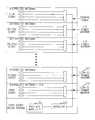
- FIG. 2is a block diagram showing the internal configuration of an apparatus for dividing power in a Pico-BTS according to the present invention.
- an area serviced by the Pico-BTSis an N-storied building.
- a signal generated by a Pico-BTS Main Unit (PMU) 211is provided to a repeater 213 .
- the signalis then amplified by a prescribed amount.
- the signal generated by the PMU 211is an intermediate frequency (IF) signal, for example, an IF signal having a band of 4.95 MHz.
- IFintermediate frequency
- the IF signalis amplified to a degree set by the repeater 213 , that is, for a radio signal of 800 MHz which is a standard size for available service.
- the signal amplified by the repeater 213is provided through a coaxial cable to a power divider, which is mounted in each story of the building.
- a power divider 215 of the first storypower-divides the signal amplified by the repeater 213 by 1/N ⁇ 1, and the amplified signal is provided to the first story.
- a power divider 217power-divides the signal previously divided by 1/N ⁇ 1 by 1/N ⁇ 2, and then provides it to the second story.
- the size of the power provided to each storyis equal, even as the distance from the repeater 213 increases.
- the power division rateis controlled so as to be inversely proportional to the distance from the repeater 213 .
- a distributed antenna 219is mounted in each story.
- the distributed antenna 219is mounted in a place, such as a window, where interference from an external BTS is minimized, the greatest interference signal generated from the external BTS occurring in the window of the building.
- the apparatus for dividing power and the method thereof in a Pico-BTShave the following advantage.
- the power division rateis controlled within the service area serviced by the Pico-BTS so as to equally divide the power, it is possible to provide equal quality of service, regardless of the distance from the PMU.
Landscapes
- Engineering & Computer Science (AREA)
- Computer Networks & Wireless Communication (AREA)
- Signal Processing (AREA)
- Mobile Radio Communication Systems (AREA)
- Radio Relay Systems (AREA)
Abstract
Description
This application claims priority based on an application entitled APPARATUS FOR DIVIDING POWER AND METHOD THEREOF IN PICO-BASE TRANSCEIVER STATION filed with the Korean Industrial Property Office on Dec. 29, 1999 and assigned Serial No. 1999-65283, the contents of which is hereby incorporated by reference.
1. Technical Field
The present invention generally relates to a pico-base transceiver station (Pico-BTS) system and, in particular, to an apparatus for dividing power and a method thereof within a service area serviced by a Pico-BTS.
2. Related Art
In general, a mobile communications system divides a service available area into cells to provide communication services. Examples of the cells include a macro cell, a micro cell, and a pico cell. The cells are arranged within a specific area to efficiently provide a differential service area. The macro cell provides the widest service area, while the micro cell provides the narrowest service area.
The pico cell is used to provide call services within buildings, specific areas such as campuses, playgrounds, airports, and shopping malls, areas where a special event or a natural disaster happens, and areas where remote-control is impossible. The pico cell is also used to complement call services of the macro cell or a mini cell having a tunnel, and to improve service quality in areas where service quality is poor.
A Pico-BTS provides communication services for the pico cell. The Pico-BTS includes a pico-main unit and a pico-radio unit. However, since the pico-radio unit is expensive, the total production cost increases. In this respect, services through the pico-main unit and a repeater have been suggested.
However, services provided through a pico-main unit have also experienced production cost problems due to the necessity of providing additional equipment (i.e., amplification equipment) when there is a large distance between the repeater and the areas to be serviced.
Accordingly, the present invention is directed to an apparatus for dividing power and a method thereof in a Pico-BTS that substantially obviate one or more of the problems resulting from limitations and disadvantages of the related art.
An object of the present invention is to provide an apparatus for equally dividing power within a service area in a Pico-BTS.
Another object of the present invention is to provide a method for equally dividing power within a service area in a Pico-BTS.
Additional features and advantages of the invention will be set forth in the description which follows, and in part will be apparent from the description, or may be learned by practice of the invention. The objectives and other advantages of the invention will be realized and attained by the structure particularly pointed out in the written description and claims thereof, as well as in the appended drawings.
To achieve these and other advantages and in accordance with the purpose of the present invention, as embodied and broadly described, an apparatus for dividing power in a Pico-BTS according to the present invention includes a repeater for amplifying a signal, which is of a prescribed size and which is provided displaced from a Pico-BTS main unit, and a power divider for controlling the signal amplified by the repeater to be equally divided into a service area serviced by the Pico-BTS.
In another aspect of the present invention, a method for dividing power in a Pico-BTS having a Pico-BTS main unit and a repeater displaced from the Pico-BTS main unit for amplifying a signal to a prescribed degree includes the steps of controlling the power division rate to equally divide the power into a service area serviced by the Pico-BTS, and power-dividing the amplified signal depending on the controlled power division rate.
A more complete appreciation of the invention, and many of the attendant advantages thereof, will be readily apparent as the same becomes better understood by reference to the following detailed description when considered in conjunction with the accompanying drawings in which like reference symbols indicate the same or similar components, and wherein:
FIG. 1 is a block diagram showing the internal configuration of an apparatus for dividing power in a Pico-BTS; and
FIG. 2 is a block diagram showing the internal configuration of an apparatus for dividing power in a Pico-BTS according to the present invention.
Reference will now be made in detail to the preferred embodiments of the present invention, examples of which are illustrated in the accompanying drawings.
It is to be understood that like reference numerals refer to like elements in the drawings. Also, in the case where it is determined that the related art or known detailed description unnecessarily makes the subject matter of the present invention unclear, the detailed description will be omitted. Terms are defined by considering functions in the present invention and depend on users, chip designers, or practices. Accordingly, their definition should be made based on the content of the entire specification of this invention.
FIG. 1 is a block diagram showing the internal configuration of an apparatus for dividing power in a Pico-BTS.
First, it is assumed that an area serviced by the Pico-BTS is an N-storied building. In this case, a signal generated from a Pico-BTS main unit (PMU)111 is provided to arepeater 113, and then is amplified to a prescribed degree. The signal amplified by therepeater 113 is provided through a coaxial cable to apower divider 115 which is mounted in each story. The power divider115 power-divides the signal amplified by therepeater 113 by one-half, and then provides the resultant signal to the first story. Next, the power divider115 power-divides the signal previously divided by one-half by another one-half, and provides the resultant signal to the second story. In the case where the signal power-divided in this way is provided to each story, it is impossible to provide an original signal if the distance from therepeater 113 is great, that is, if the size of the power provided to the N-th story is weak. To provide the original signal, an amplifier has been additionally required. For this reason, an increase in cost has been experienced.
FIG. 2 is a block diagram showing the internal configuration of an apparatus for dividing power in a Pico-BTS according to the present invention.
First, it is assumed that an area serviced by the Pico-BTS is an N-storied building. In this case, a signal generated by a Pico-BTS Main Unit (PMU)211 is provided to arepeater 213. The signal is then amplified by a prescribed amount. The signal generated by thePMU 211 is an intermediate frequency (IF) signal, for example, an IF signal having a band of 4.95 MHz. The IF signal is amplified to a degree set by therepeater 213, that is, for a radio signal of 800 MHz which is a standard size for available service. The signal amplified by therepeater 213 is provided through a coaxial cable to a power divider, which is mounted in each story of the building.
Apower divider 215 of the first story power-divides the signal amplified by therepeater 213 by 1/N−1, and the amplified signal is provided to the first story. Next, apower divider 217 power-divides the signal previously divided by 1/N−1 by 1/N−2, and then provides it to the second story. In the case where the signal power-divided in this way is provided to each story, the size of the power provided to each story is equal, even as the distance from therepeater 213 increases. Thus, it is possible to minimize power consumption and provide an original signal. This is because the power division rate is controlled so as to be inversely proportional to the distance from therepeater 213.
Furthermore, adistributed antenna 219 is mounted in each story. Thedistributed antenna 219 is mounted in a place, such as a window, where interference from an external BTS is minimized, the greatest interference signal generated from the external BTS occurring in the window of the building.
As previously mentioned, the apparatus for dividing power and the method thereof in a Pico-BTS, according to the present invention, have the following advantage.
Since the power division rate is controlled within the service area serviced by the Pico-BTS so as to equally divide the power, it is possible to provide equal quality of service, regardless of the distance from the PMU.
While the present invention has been described and illustrated herein with reference to the preferred embodiments thereof, it will be apparent to those skilled in the art that various modifications and variations can be made therein without departing from the spirit and scope of the invention. Thus, it is intended that the present invention cover the modifications and variations of this invention that come within the scope of the appended claims and their equivalents.
Claims (12)
1. An apparatus for dividing power in a pico-base transceiver station (Pico-BTS), comprising:
a repeater for amplifying, to a prescribed degree of amplification, a signal provided by a Pico-BTS main unit; and
a power divider for controlling the signal amplified by the repeater so that the signal is equally divided within a service area serviced by the Pico-BTS and a power division rate of the signal is inversely proportional to a distance from the repeater to a point at which the power-dividing takes place.
2. The apparatus ofclaim 1 , further comprising a distributed antenna connected to the power divider for receiving a radio signal.
3. The apparatus ofclaim 2 , wherein the distributed antenna is mounted in a place where interference from an external base transceiver station (BTS), not the Pico-BTS, is minimized.
4. The apparatus ofclaim 1 , wherein the Pico-BTS main unit generates an intermediate frequency, and the repeater amplifies the intermediate frequency generated by the Pico-BTS main unit at a standard frequency for available service.
5. The apparatus ofclaim 1 , wherein said power divider comprises a plurality of power dividers, and wherein a first power divider divides a signal by 1/(N−1), and a second power divider divides a signal by 1/(N−2), wherein N is a total number of stories of a building.
6. A method for dividing power in a Pico-BTS provided with a Pico-BTS main unit and a repeater for amplifying a signal to a predetermined degree of amplification, said repeater being displaced from the Pico-BTS main unit, the method comprising the steps of:
controlling a power division rate so as to equally divide the power within a service area serviced by the Pico-BTS; and
power-dividing the amplified signal depending on the controlled power division rate which is inversely proportional to a distance from the repeater to a point at which the power-dividing takes place.
7. An apparatus for dividing power in pico-base transceiver station (Pico-BTS), comprising:
repeater means for receiving a signal provided by a Pico-BTS main unit and for amplifying the received signal to a prescribed degree of amplification; and
power divider means for controlling the amplified signal so that it is equally divided within a service area serviced by the Pico-BTS and a power division rate of the signal is inversely proportional to a distance from the repeater to a point at which the power-dividing takes place.
8. The apparatus ofclaim 7 , said apparatus further comprising distributed antenna means connected to the power divider means for receiving a radio signal.
9. The apparatus ofclaim 8 , wherein the distributed antenna means is mounted in a place where interference from an external base transceiver station (BTS), not the Pico-BTS, is minimized.
10. The apparatus ofclaim 7 , wherein the Pico-BTS main unit generates an intermediate frequency (IF) signal, and the repeater means amplifies the IF signal at a standard frequency for available service.
11. The apparatus ofclaim 7 , wherein said power divider means comprises a plurality of power dividers, and wherein a first power divider means divides a signal by 1/(N−2), and a second power divider means divides a signal by 1/(N−1), wherein N is a total number of stories of a building.
12. A method for dividing power in a Pico-BTS, comprising the steps of:
providing a Pico-BTS main unit and a repeater for amplifying a signal provided by the Pico-BTS main unit to a prescribed degree of amplification;
controlling a power division rate so as to equally divide the power within a service area serviced by the Pico-BTS; and
power-dividing the amplified signal depending on the controlled power division rate which is inversely proportional to a distance from the repeater to a point at which the power-dividing takes place.
Applications Claiming Priority (2)
| Application Number | Priority Date | Filing Date | Title |
|---|---|---|---|
| KR1019990065283AKR100630195B1 (en) | 1999-12-29 | 1999-12-29 | Apparatus and method for power distribution of pico-base stations |
| KR1999-65283 | 1999-12-29 |
Publications (2)
| Publication Number | Publication Date |
|---|---|
| US20010006903A1 US20010006903A1 (en) | 2001-07-05 |
| US6785555B2true US6785555B2 (en) | 2004-08-31 |
Family
ID=19632487
Family Applications (1)
| Application Number | Title | Priority Date | Filing Date |
|---|---|---|---|
| US09/750,300Expired - LifetimeUS6785555B2 (en) | 1999-12-29 | 2000-12-29 | Apparatus for dividing power and method thereof in pico-base transceiver station |
Country Status (2)
| Country | Link |
|---|---|
| US (1) | US6785555B2 (en) |
| KR (1) | KR100630195B1 (en) |
Families Citing this family (3)
| Publication number | Priority date | Publication date | Assignee | Title |
|---|---|---|---|---|
| WO2003069815A1 (en)* | 2002-01-30 | 2003-08-21 | Telefonaktiebolaget Lm Ericsson (Publ) | Method and system for transmission of carrier signals between first and second antenna networks |
| JP3749513B2 (en) | 2002-06-25 | 2006-03-01 | 東芝テック株式会社 | Wireless communication system |
| ES2554541T3 (en)* | 2008-02-08 | 2015-12-21 | Adc Telecommunications, Inc | A company mobile network to provide a wireless (cellular) mobile phone service using a licensed radio frequency spectrum and an internet protocol return network |
Citations (6)
| Publication number | Priority date | Publication date | Assignee | Title |
|---|---|---|---|---|
| JPS58100502A (en)* | 1981-12-09 | 1983-06-15 | Mitsubishi Electric Corp | array antenna device |
| US5561397A (en)* | 1995-05-15 | 1996-10-01 | Unisys Corporation | Solid state amplifier for microwave transmitter |
| US5946622A (en)* | 1996-11-19 | 1999-08-31 | Ericsson Inc. | Method and apparatus for providing cellular telephone service to a macro-cell and pico-cell within a building using shared equipment |
| US6035218A (en)* | 1996-05-09 | 2000-03-07 | Samsung Electronics Co., Ltd. | Radio signal repeating apparatus of a code division multiple access communication system |
| US6374119B1 (en)* | 1999-05-27 | 2002-04-16 | Hansol Pcs Co. Ltd. | System and method for in-building mobile communications |
| US6560441B1 (en)* | 1999-04-15 | 2003-05-06 | Transcept, Inc. | Low noise in-building distribution network for wireless signals |
- 1999
- 1999-12-29KRKR1019990065283Apatent/KR100630195B1/ennot_activeExpired - Fee Related
- 2000
- 2000-12-29USUS09/750,300patent/US6785555B2/ennot_activeExpired - Lifetime
Patent Citations (6)
| Publication number | Priority date | Publication date | Assignee | Title |
|---|---|---|---|---|
| JPS58100502A (en)* | 1981-12-09 | 1983-06-15 | Mitsubishi Electric Corp | array antenna device |
| US5561397A (en)* | 1995-05-15 | 1996-10-01 | Unisys Corporation | Solid state amplifier for microwave transmitter |
| US6035218A (en)* | 1996-05-09 | 2000-03-07 | Samsung Electronics Co., Ltd. | Radio signal repeating apparatus of a code division multiple access communication system |
| US5946622A (en)* | 1996-11-19 | 1999-08-31 | Ericsson Inc. | Method and apparatus for providing cellular telephone service to a macro-cell and pico-cell within a building using shared equipment |
| US6560441B1 (en)* | 1999-04-15 | 2003-05-06 | Transcept, Inc. | Low noise in-building distribution network for wireless signals |
| US6374119B1 (en)* | 1999-05-27 | 2002-04-16 | Hansol Pcs Co. Ltd. | System and method for in-building mobile communications |
Also Published As
| Publication number | Publication date |
|---|---|
| US20010006903A1 (en) | 2001-07-05 |
| KR100630195B1 (en) | 2006-09-29 |
| KR20010065406A (en) | 2001-07-11 |
Similar Documents
| Publication | Publication Date | Title |
|---|---|---|
| AU680524B2 (en) | Cellular radio system | |
| FI109955B (en) | Communication control technology for a radio telephone system including microcells | |
| AU668798B2 (en) | Radio coverage in closed environments | |
| US20060246886A1 (en) | Network support for campus and building security | |
| CA2399862A1 (en) | A distributed smart antenna system | |
| US5604789A (en) | Method and system for providing a digital wireless local loop | |
| JPS62136930A (en) | mobile radio communication system | |
| US20010046840A1 (en) | Apparatus for transmitting and receiving radio signals in a pico-BTS | |
| GB0216291D0 (en) | Improvements in or relating to cellular communications systems | |
| US5960352A (en) | Multilayer cellular mobile radio network with optimized frequency re-use plan, and associated method | |
| US6650907B1 (en) | Method for producing a semiconductor storage device | |
| AU7494296A (en) | Radio communication system | |
| US6785555B2 (en) | Apparatus for dividing power and method thereof in pico-base transceiver station | |
| CN101174887B (en) | Transmission Scheduling Method and System Applied to Relay Station Assisted Wireless Communication System | |
| WO2025060537A1 (en) | Mimo communication system and control method for feeding in signals at two ends of leaky cable | |
| EP0641504A1 (en) | A method for cascading of microbases | |
| US20180262267A1 (en) | Methods and apparatus for transmitting data in a network | |
| EP0690638A2 (en) | Method and system for providing a digital wireless local loop | |
| CN209389202U (en) | A kind of aerial mounting structure and communication tower | |
| FI105373B (en) | A method for measuring uplink interference in a cellular radio system and base station | |
| JP2940886B2 (en) | Channel switching method between multiple wireless zones | |
| CN109980331A (en) | A kind of aerial mounting structure and communication tower | |
| US6236651B1 (en) | Base station | |
| KR100304919B1 (en) | Cellular Mobile Communication System | |
| JPH08265840A (en) | Mobile radio communication system |
Legal Events
| Date | Code | Title | Description |
|---|---|---|---|
| AS | Assignment | Owner name:SAMSUNG ELECTRONICS CO., LTD., KOREA, REPUBLIC OF Free format text:ASSIGNMENT OF ASSIGNORS INTEREST;ASSIGNOR:PARK, JONG-MYUNG;REEL/FRAME:011423/0350 Effective date:20001218 | |
| STCF | Information on status: patent grant | Free format text:PATENTED CASE | |
| FEPP | Fee payment procedure | Free format text:PAYOR NUMBER ASSIGNED (ORIGINAL EVENT CODE: ASPN); ENTITY STATUS OF PATENT OWNER: LARGE ENTITY | |
| FPAY | Fee payment | Year of fee payment:4 | |
| FEPP | Fee payment procedure | Free format text:PAYER NUMBER DE-ASSIGNED (ORIGINAL EVENT CODE: RMPN); ENTITY STATUS OF PATENT OWNER: LARGE ENTITY Free format text:PAYOR NUMBER ASSIGNED (ORIGINAL EVENT CODE: ASPN); ENTITY STATUS OF PATENT OWNER: LARGE ENTITY | |
| FPAY | Fee payment | Year of fee payment:8 | |
| FPAY | Fee payment | Year of fee payment:12 |