US6785531B2 - Dual-function removable reversable unit for radio and telephone - Google Patents
Dual-function removable reversable unit for radio and telephoneDownload PDFInfo
- Publication number
- US6785531B2 US6785531B2US09/815,209US81520901AUS6785531B2US 6785531 B2US6785531 B2US 6785531B2US 81520901 AUS81520901 AUS 81520901AUS 6785531 B2US6785531 B2US 6785531B2
- Authority
- US
- United States
- Prior art keywords
- radio
- functions
- module
- telephone
- cavity
- Prior art date
- Legal status (The legal status is an assumption and is not a legal conclusion. Google has not performed a legal analysis and makes no representation as to the accuracy of the status listed.)
- Expired - Fee Related, expires
Links
Images

Classifications
- H—ELECTRICITY
- H04—ELECTRIC COMMUNICATION TECHNIQUE
- H04B—TRANSMISSION
- H04B1/00—Details of transmission systems, not covered by a single one of groups H04B3/00 - H04B13/00; Details of transmission systems not characterised by the medium used for transmission
- H04B1/38—Transceivers, i.e. devices in which transmitter and receiver form a structural unit and in which at least one part is used for functions of transmitting and receiving
- H04B1/3827—Portable transceivers
- H04B1/3833—Hand-held transceivers
- H04B1/3838—Arrangements for reducing RF exposure to the user, e.g. by changing the shape of the transceiver while in use
Definitions
- This inventiongenerally relates to a communication unit used in a motor vehicle. More specifically, this invention relates to a device that can be used to perform the functions of both a radio and a telephone while interfacing with the main communication unit installed in a motor vehicle.
- the audio function and telephone functionscan be combined in one secure panel such that common components can be shared. Additionally, thieves can be discouraged by allowing an occupant to remove the entire radio bezel when the operator leaves the vehicle so the car radio loses its appearance and functionality as a car radio. Further, some are designed such that an operator may remove only an essential portion of a bezel to render the radio inoperable. Removing only the bezel is easier than requiring the removal of the entire radio since the overall radio tends to be heavy and bulky. Similarly, there have been a number of anti-theft devices have been developed to prevent the theft of the mobile phone as a separate unit. Such devices may include providing a protective housing for the mobile phone or locking the mobile phone in a docking unit. However, having separate anti-theft devices for the audio system and the communication device increase the overall cost of such equipment.
- the communication system and the audio systemin one unit to reduce the complexity and expense of the overall system. Integration of both the systems will prevent additional costs of having more man one anti-theft device installed in one automobile. Further, the audio function and telephone functions can be combined in one secure panel such that common components can be shared.
- the present inventionprovides for a modular communication system to be installed in a motor vehicle.
- the communication systemin accordance with the teachings of the present invention includes a base unit and a removable unit.
- the base unitis provided with a cavity to insert the removable unit.
- the communication systemis rendered inoperable when the removable unit is removed from the base unit.
- the removable unitis provided with two surfaces that perform different function. In particular when the removable unit is inserted into the base unit and the first surface is exposed then the communication system operates as a radio player.
- the removable unitis capable of being reversed such that second surface is exposed, then the communication system operates as a telephone unit.
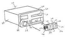
- FIG. 1is a perspective representation of the motor vehicle incorporating the reversible unit according to the first preferred embodiment of the invention
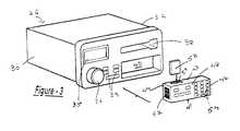
- FIG. 2is a perspective view of the reversible unit with the first surface exposed according to the preferred embodiment of the invention.
- FIG. 3is a perspective view of the reversible unit with the second surface exposed according to the preferred embodiment of the invention.
- FIG. 1A representative motor vehicle incorporating the features of the present invention is shown in FIG. 1 and typically designated by referenced number 10 .
- the motor vehicle 10defines an interior compartment 12 and an instrument panel 14 .
- the instrument panel 14is generally installed in the vicinity of a windshield (not shown) in the motor vehicle 10 .
- the instrument panel 14which functions to incorporate a number of controls easily accessible to an occupant of a motor vehicle typically comprises a steering wheel system 16 installed in the driver side, a glove compartment (not shown) installed in the passenger side of the motor vehicle 10 and a central console 20 .
- the central console 20typically includes a plurality of controls easily accessible to an occupant of a motor vehicle 10 to adjust a number of user options provided in any motor vehicle.
- controlsinclude an HVAC System 22 , a display unit 23 associated with the HVAC system for displaying the temperature of the interior of the motor vehicle and/or the temperature outside the motor vehicle, the intensity or the speed of the blower unit and other features such as time and the distance traveled by the motor vehicle 10 .
- the central console 20also includes a communication system 24 .
- the central consolemay or may not include all of the above features.
- the central console 20is an integral part of the instrument panel 14 although it is possible to make the central console 20 modular and separate from the instrument panel 14 .
- the communication system 24typically comprises a base unit 26 and a removable unit 28 .
- the base unit 26is fixedly attached to the central console 20 and is preferably nested in a cavity (not shown) provided in the central console 20 .
- the base unit 26can be an integral part of the central console 20 .
- the base unit 26typically functions as a vehicle interface unit between the vehicular parts and the removable unit 28 .
- the base unit 26is connected to a speaker unit (not shown).
- the base unit 26is also connected to a navigation system (not shown) and an external antenna (not shown) typically present in any motor vehicle.
- the base unit 26is rectangular in shape and comprises sides 30 and 32 parallel to each other. As discussed above, the base unit 26 is inserted inside a cavity provided in the central console 20 such that the base unit 26 is horizontally inserted. Between the sides 30 and 32 the base unit 26 comprises a front panel 34 .
- the front panel 34typically is an integral part of the base unit 26 . Alternatively is may be formed of a separate piece that is removable. As seen in FIG. 1, preferably the front panel 34 is flush with the front face 27 central console 20 of the instrument panel 14 . Alternatively, it is also possible that the base unit 26 is protruding outwards towards the occupants such that the front panel 34 is not flush with the front face 27 central console 20 .
- the preference of whether the front panel 34 of the base unit 26 is flush with the central console 20 or is protruding outside the central console 20is a matter of aesthetics and will not affect the function or the use of the base unit 26 .
- the front panel 34typically has a plurality of controls associated with it.
- the front panel 34has a volume control 36 for increasing or reducing the volume, an audio unit 38 and a display monitor 35 .
- the font panel 34may also have controls 39 for rewinding or fast-forwarding a tape or a CD of the audio unit 38 .
- the audio unit 38includes a cassette or a CD player for inserting either a cassette or a CD to enable an occupant to listen to programs or music of the occupant's choice.
- the front panel 34 of the base unit 26may or may not include all of the features or may omit some of the features listed above.
- the display monitor 35is conventional in art and displays a plurality of images, numbers or both. For example, if the CD player is operational then the display monitor 35 will let the occupant of the vehicle know what song number is being played.
- the front panel 34 of the base unit 26includes a cavity or opening 40 .
- the cavity 40is at the bottom of the base unit 26 , it must be understood that the cavity 40 can be placed anywhere in the base unit 26 .
- the inside (generally indicated by reference numeral 41 ) of the cavity 40has a connector port to allow connection between the removable unit 28 and the base unit 26 (as will be explained later).
- the removable unit 28is capable of being inserted into the cavity 40 of the base unit 26 .
- the removable unit 28is rectangular in shape and has the dimension such that it snuggly fits into the cavity 40 provided in the base unit 26 .
- the removable unitis inserted horizontally into the cavity of the base unit 26 .
- the removable unit 28is provided with means to eject the removable unit 28 from the base unit 26 .
- the means (not shown) to eject the removable unit 28 , from the base unit 26may be in the form of a press button, or an electronically controlled switch.
- the means to eject the removable unit 28may be provided in the base unit 26 .
- the base unit 26 or the removable unit 28will have a snap fit configuration or a snap fit clip such that the removable unit 28 may be snap fitted into the base unit 26 .
- the removable unit 28is separate form the base unit 26 .
- the removable unit 28When the removable unit 28 is removed from the base unit 26 , it renders the base unit 26 inoperable.
- the communication system 24may be rendered inoperable.
- the removable unit 28typically has two sides 42 , 44 respectively, a top surface 43 and a bottom surface 45 .
- the removable unit 28defines a first surface 46 and a second surface 48 parallel to each other and placed between the sides 40 and 42 of the removable unit 28 .
- the removable unit 28is inserted into the cavity 40 such that the sides 42 and 44 are parallel to the sides 30 and 32 of the base unit 26 .
- the first surface 46 or the second surface 48is exposed to the occupant.
- the exposed surface 46 or 48is flush with the front panel 34 of the base unit 26 such that when the base unit 26 and the removable unit 28 are fitted together they give the appearance of a single unit.
- the first surface 46 of the removable unit 28has a plurality of controls generally designated by reference number 50 that enables the first surface 46 to perform a particular function.
- the plurality of controls 50are in the form of soft key buttons. Alternatively, they may be in the form of a touch pad.
- the plurality of controls 50 on the first surface 46is similar to that of a typical radio player. Therefore, when the removable unit 28 is inserted into the base unit 26 and the first surface 46 is exposed to the occupant, the communication system 14 functions as a radio player 52 .
- the plurality of controls 50comprises multiple programming buttons that enable the occupant to the tune and program the radio player 52 .
- the plurality of controlsmay also include controls for changing the frequency of the radio player. Additionally, the plurality of controls 50 present on the first surface 46 may also include controls for turning on and off the radio player.
- the first surface 45may or may not include all the features mentioned above.
- the plurality of controls 50is internally connected to a first communication port 60 on side 42 of the removable unit 28 .
- a connectionis established between the first communication port 60 and the connector port on the base unit 26 .
- the first communication port 60is optically or electronically connected to the connector base on the base unit 26 .
- the particular operationwill be displayed in the display monitor 35 present on the base unit. For example, if the occupant operates the control for changing the frequency, the display monitor will display if what particular frequency is being operated.
- the first surface 46preferably includes a pager unit 53 .
- the pager unit 53by itself is conventional in art.
- the pager unitis capable of receiving a text and/or alphanumeric messages.
- the pager unitis integrally attached to the first surface 46 .
- the first surface 46internally includes a circuit (not shown) and a pager antenna (not shown).
- the pager unit 53is electronically connected to the base unit 26 through the first communication port 60 .
- the pager unit 53has its own display unit 55 .
- the pager unit 53is present on the second surface 48 of the removable unit 28 .
- the second surface 48 of the removable unit 28is substantially parallel to the first surface 46 of the removable unit 28 such that when the removable unit 28 is reversed, the second surface 48 is exposed to the occupant.
- the second surface 48also comprises a plurality of controls generally designated by reference numeral 54 .
- the plurality of controls 54 on the second surface 48is different from the plurality of controls 50 on the first surface 46 .
- the controls 54 displayed on the second surface 48are typical to controls found in any telephone.
- the plurality of controls 54may be in the form of soft key buttons (as shown) or alternatively in the form of a touch pad.
- the plurality of controls 54may include a control button to send and receive controls to enable an occupant to dial the desired number and to send the number. It may include a control button to end calls, a control button to recall a number, etc.
- the second surface 48may also include an angled microphone (not shown) to enable the user to talk on the telephone while operating the motor vehicle 10 .
- the plurality of controls 54is internally connected to a second communication port 62 .
- a connectionis established between the second communication port 62 and the connector port in the base unit 26 .
- the second communication port 62is optically or electronically connected to the connector base on the base unit 26 .
- the particular operationwill be displayed in the display monitor 35 present on the base unit 26 . For example, if the occupant dials a particular number, the display monitor 35 will display the being dialed.
- the top surface 43 of the removable unitincludes an opening 57 to insert a SIM Card 58 to expand the memory of the telephone unit 56 to store numbers.
- the opening 57may be provided anywhere in the removable unit 28 to insert a SIM card or any other device capable of expanding the memory of the removable unit 28 .
- the removable unit 28is inserted into the cavity 40 provided in the base unit 26 .
- the first surface 46is exposed to the occupant such that the communication unit 24 functions as a radio player 52 .
- the base unit 26also includes a number of sensors (not shown). Therefore, when the first surface 46 is exposed to the occupant of a motor vehicle 10 , a plurality of sensors are sent to the communication system 24 such that the audio unit 38 is inoperable.
- the removable unit 28is also connected to the display monitor 35 present in the base unit 26 through a plurality of sensors.
- the display monitor 35will display the mode or the function that the communication system 24 is performing. Therefore, when the first surface 46 is exposed to the occupant, the display monitor 35 will display that the communication unit 24 is being used as a radio player 52 and may alternatively also display the preferred radio channel that the occupant is currently hearing.
- the first surface 46 of the removable unit 28may also include a pager unit 53 . Therefore, in addition to function as a radio player 52 , the first surface 46 may also receive text/alphanumeric pages. Both the radio player 52 and the pager unit 53 can operate at the same time. Therefore, when a page arrives, the display monitor 35 will display the message. If the occupant desires to return the call, in one simple motion, can reverse the removable unit 28 such that the second surface 48 is exposed.
- the occupantmay remove and reverse the removable unit 28 such that the second communicator port 62 is in communication with the base unit 26 .
- the communication system 24now functions as a telephone unit 56 that enables the occupant to make a call.
- the display monitor 35will display the number dialed by the occupant or will also display the incoming call received by the occupant. It is preferred that when the communication unit 24 functions as a telephone unit 56 , the audio unit 38 cannot be used. Alternatively, it is possible that the communication system 24 performs only one function at a time. In other words, the communication system may be used only as a radio player 52 or a telephone unit 56 or an audio unit 38 .
- the reversible radio-telephone unitis used in a motor vehicle, it must be understood that the application of the is not limited to such uses.
- the removable unit 28allows a complete contact to be established such that one unit may be used both as a telephone unit or a radio player in one easy movement by the occupant.
- the above designallows for less controls to be present in the central console.
Landscapes
- Engineering & Computer Science (AREA)
- Computer Networks & Wireless Communication (AREA)
- Signal Processing (AREA)
- Fittings On The Vehicle Exterior For Carrying Loads, And Devices For Holding Or Mounting Articles (AREA)
Abstract
Description
Claims (39)
Priority Applications (1)
| Application Number | Priority Date | Filing Date | Title |
|---|---|---|---|
| US09/815,209US6785531B2 (en) | 2001-03-22 | 2001-03-22 | Dual-function removable reversable unit for radio and telephone |
Applications Claiming Priority (1)
| Application Number | Priority Date | Filing Date | Title |
|---|---|---|---|
| US09/815,209US6785531B2 (en) | 2001-03-22 | 2001-03-22 | Dual-function removable reversable unit for radio and telephone |
Publications (2)
| Publication Number | Publication Date |
|---|---|
| US20020137541A1 US20020137541A1 (en) | 2002-09-26 |
| US6785531B2true US6785531B2 (en) | 2004-08-31 |
Family
ID=25217177
Family Applications (1)
| Application Number | Title | Priority Date | Filing Date |
|---|---|---|---|
| US09/815,209Expired - Fee RelatedUS6785531B2 (en) | 2001-03-22 | 2001-03-22 | Dual-function removable reversable unit for radio and telephone |
Country Status (1)
| Country | Link |
|---|---|
| US (1) | US6785531B2 (en) |
Cited By (40)
| Publication number | Priority date | Publication date | Assignee | Title |
|---|---|---|---|---|
| US20030224841A1 (en)* | 2002-05-28 | 2003-12-04 | Pioneer Corporation | Handfree call apparatus and handfree call method |
| US20060134959A1 (en)* | 2004-12-16 | 2006-06-22 | Jesse Ellenbogen | Incorporating a portable digital music player into a vehicle audio system |
| US20060277555A1 (en)* | 2005-06-03 | 2006-12-07 | Damian Howard | Portable device interfacing |
| US20080049949A1 (en)* | 2006-08-18 | 2008-02-28 | Snider Chris R | Lightweight audio system for automotive applications and method |
| US20080157941A1 (en)* | 2005-12-14 | 2008-07-03 | Siemens Vdo Automotive Ag | Electronic Device to Be Incorporated Into a Motor Vehicle in Order to Help Retrieve the Device Following a Theft |
| US20080215240A1 (en)* | 2006-12-18 | 2008-09-04 | Damian Howard | Integrating User Interfaces |
| US20080212793A1 (en)* | 2007-01-09 | 2008-09-04 | Honda Motor Co., Ltd. | Arrangement structure of sound system in motorcycle |
| US20090130884A1 (en)* | 2007-11-15 | 2009-05-21 | Bose Corporation | Portable device interfacing |
| US20090154724A1 (en)* | 2005-09-28 | 2009-06-18 | Clarion Co., Ltd. | On-vehicle acoustics apparatus |
| US20130245882A1 (en)* | 2012-03-14 | 2013-09-19 | Christopher P. Ricci | Removable, configurable vehicle console |
| US8760886B2 (en) | 2006-08-18 | 2014-06-24 | Delphi Technologies, Inc. | Lightweight audio system for automotive applications and method |
| US8793034B2 (en) | 2011-11-16 | 2014-07-29 | Flextronics Ap, Llc | Feature recognition for configuring a vehicle console and associated devices |
| US9098367B2 (en) | 2012-03-14 | 2015-08-04 | Flextronics Ap, Llc | Self-configuring vehicle console application store |
| US9237685B2 (en) | 2006-08-18 | 2016-01-12 | Delphi Technologies, Inc. | Lightweight audio system for automotive applications and method |
| US9928734B2 (en) | 2016-08-02 | 2018-03-27 | Nio Usa, Inc. | Vehicle-to-pedestrian communication systems |
| US9946906B2 (en) | 2016-07-07 | 2018-04-17 | Nio Usa, Inc. | Vehicle with a soft-touch antenna for communicating sensitive information |
| US9963106B1 (en) | 2016-11-07 | 2018-05-08 | Nio Usa, Inc. | Method and system for authentication in autonomous vehicles |
| US9984572B1 (en) | 2017-01-16 | 2018-05-29 | Nio Usa, Inc. | Method and system for sharing parking space availability among autonomous vehicles |
| US10031521B1 (en) | 2017-01-16 | 2018-07-24 | Nio Usa, Inc. | Method and system for using weather information in operation of autonomous vehicles |
| US10074223B2 (en) | 2017-01-13 | 2018-09-11 | Nio Usa, Inc. | Secured vehicle for user use only |
| US10234302B2 (en) | 2017-06-27 | 2019-03-19 | Nio Usa, Inc. | Adaptive route and motion planning based on learned external and internal vehicle environment |
| US10249104B2 (en) | 2016-12-06 | 2019-04-02 | Nio Usa, Inc. | Lease observation and event recording |
| US10286915B2 (en) | 2017-01-17 | 2019-05-14 | Nio Usa, Inc. | Machine learning for personalized driving |
| US10369974B2 (en) | 2017-07-14 | 2019-08-06 | Nio Usa, Inc. | Control and coordination of driverless fuel replenishment for autonomous vehicles |
| US10369966B1 (en) | 2018-05-23 | 2019-08-06 | Nio Usa, Inc. | Controlling access to a vehicle using wireless access devices |
| US10410250B2 (en) | 2016-11-21 | 2019-09-10 | Nio Usa, Inc. | Vehicle autonomy level selection based on user context |
| US10410064B2 (en) | 2016-11-11 | 2019-09-10 | Nio Usa, Inc. | System for tracking and identifying vehicles and pedestrians |
| US10464530B2 (en) | 2017-01-17 | 2019-11-05 | Nio Usa, Inc. | Voice biometric pre-purchase enrollment for autonomous vehicles |
| US10471829B2 (en) | 2017-01-16 | 2019-11-12 | Nio Usa, Inc. | Self-destruct zone and autonomous vehicle navigation |
| US10606274B2 (en) | 2017-10-30 | 2020-03-31 | Nio Usa, Inc. | Visual place recognition based self-localization for autonomous vehicles |
| US10635109B2 (en) | 2017-10-17 | 2020-04-28 | Nio Usa, Inc. | Vehicle path-planner monitor and controller |
| US10694357B2 (en) | 2016-11-11 | 2020-06-23 | Nio Usa, Inc. | Using vehicle sensor data to monitor pedestrian health |
| US10692126B2 (en) | 2015-11-17 | 2020-06-23 | Nio Usa, Inc. | Network-based system for selling and servicing cars |
| US10708547B2 (en) | 2016-11-11 | 2020-07-07 | Nio Usa, Inc. | Using vehicle sensor data to monitor environmental and geologic conditions |
| US10710633B2 (en) | 2017-07-14 | 2020-07-14 | Nio Usa, Inc. | Control of complex parking maneuvers and autonomous fuel replenishment of driverless vehicles |
| US10717412B2 (en) | 2017-11-13 | 2020-07-21 | Nio Usa, Inc. | System and method for controlling a vehicle using secondary access methods |
| US10837790B2 (en) | 2017-08-01 | 2020-11-17 | Nio Usa, Inc. | Productive and accident-free driving modes for a vehicle |
| US10897469B2 (en) | 2017-02-02 | 2021-01-19 | Nio Usa, Inc. | System and method for firewalls between vehicle networks |
| US10935978B2 (en) | 2017-10-30 | 2021-03-02 | Nio Usa, Inc. | Vehicle self-localization using particle filters and visual odometry |
| US20220399910A1 (en)* | 2021-06-09 | 2022-12-15 | Siyata Mobile Inc. | Mobile conversion apparatus for docking cellular data devices |
Families Citing this family (22)
| Publication number | Priority date | Publication date | Assignee | Title |
|---|---|---|---|---|
| US8868023B2 (en) | 2008-01-04 | 2014-10-21 | 3D Radio Llc | Digital radio systems and methods |
| DE10322614A1 (en)* | 2003-05-20 | 2004-10-07 | Daimlerchrysler Ag | Motor vehicle communications device has docking station incorporating computer connected to central unit, and has terminal implementing vehicle control, entertainment and browsing functions |
| US7532880B2 (en)* | 2003-12-17 | 2009-05-12 | General Motors Corporation | Telematics unit having interactive radio features |
| US7774104B2 (en)* | 2006-12-27 | 2010-08-10 | Fujitsu Ten Limited | Electronic apparatus and electronic system |
| US7860643B2 (en)* | 2006-12-28 | 2010-12-28 | Fujitsu Ten Limited | In-vehicle detachably electronic apparatus and in-vehicle electronic system |
| JP4842785B2 (en)* | 2006-12-04 | 2011-12-21 | 富士通テン株式会社 | In-vehicle electronic system and in-vehicle electronic device |
| US8706396B2 (en)* | 2006-12-28 | 2014-04-22 | Fujitsu Ten Limited | Electronic apparatus and electronic system |
| JP2008137559A (en)* | 2006-12-04 | 2008-06-19 | Fujitsu Ten Ltd | On-vehicle electronic system, on-vehicle electronic apparatus, and power supply control method of portable electronic apparatus |
| US7904236B2 (en)* | 2006-12-28 | 2011-03-08 | Fujitsu Ten Limited | Electronic apparatus and electronic system |
| US20080159557A1 (en)* | 2006-12-27 | 2008-07-03 | Fujitsu Ten Limited | Electronic apparatus, electronic system and method of controlling sound output |
| US7684200B2 (en)* | 2006-12-28 | 2010-03-23 | Fujitsu Ten Limited | Electronic apparatus and electronic system |
| US20080162044A1 (en)* | 2006-12-28 | 2008-07-03 | Fujitsu Ten Limited | In-vehicle electronic apparatus and in-vehicle electronic system |
| US7765046B2 (en)* | 2006-12-28 | 2010-07-27 | Fujitsu Ten Limited | In-vehicle electronic apparatus and in-vehicle electronic system |
| JP2008141076A (en)* | 2006-12-04 | 2008-06-19 | Fujitsu Ten Ltd | Attaching/detaching device of mobile electronic equipment |
| US20080157999A1 (en)* | 2006-12-28 | 2008-07-03 | Fujitsu Ten Limited | Electronic apparatus, electronic system and method of controlling audio output |
| US20080161950A1 (en)* | 2006-12-28 | 2008-07-03 | Fujitsu Ten Limited | Electronic system, electronic apparatus and method of operating audio unit |
| US7869196B2 (en)* | 2006-12-28 | 2011-01-11 | Fujitsu Ten Limited | Electronic apparatus |
| ATE512833T1 (en)* | 2007-01-26 | 2011-07-15 | Harman Becker Automotive Sys | ATTACHING A MOBILE ELECTRONIC DEVICE TO A VEHICLE AUDIO DEVICE |
| US20110254687A1 (en)* | 2010-04-15 | 2011-10-20 | Nokia Corporation | Method and apparatus for activating a device |
| US9432716B2 (en) | 2010-10-08 | 2016-08-30 | Calvin Liu | In-vehicle display for audio-video distribution |
| US8755951B2 (en)* | 2011-06-10 | 2014-06-17 | Concept Enterprises, Inc. | Multimedia system for vehicle with portable dash pad |
| US10084498B2 (en)* | 2015-09-16 | 2018-09-25 | Gm Global Technology Operations, Llc. | Configurable communications module with replaceable network access device |
Citations (15)
| Publication number | Priority date | Publication date | Assignee | Title |
|---|---|---|---|---|
| US5107244A (en) | 1989-07-12 | 1992-04-21 | Pioneer Electronic Corporation | Burglarproof device for electronic equipment adapted to be mounted in vehicles |
| US5202913A (en) | 1988-12-30 | 1993-04-13 | Saab Automobile Aktiebolag | Communications unit for fitting in vehicles |
| US5243640A (en) | 1991-09-06 | 1993-09-07 | Ford Motor Company | Integrated cellular telephone and vehicular audio system |
| US5312263A (en) | 1993-08-12 | 1994-05-17 | Ford Motor Company | Removable radio bezel connector |
| US5333177A (en) | 1991-10-19 | 1994-07-26 | Cell Port Labs, Inc. | Universal connection for cellular telephone interface |
| US5418836A (en) | 1991-11-13 | 1995-05-23 | Kabushiki Kaisha Honda Access | Radiotelephone equipment for use in vehicle |
| US5535274A (en) | 1991-10-19 | 1996-07-09 | Cellport Labs, Inc. | Universal connection for cellular telephone interface |
| US5537673A (en)* | 1992-05-25 | 1996-07-16 | Pioneer Electronic Corporation | Car stereo having a removable panel |
| US5798984A (en) | 1996-11-22 | 1998-08-25 | Eta Sa Fabriques D'ebauches | Timepiece including a receiving and/or transmitting antenna for radio broadcast signals |
| US5836496A (en) | 1997-06-06 | 1998-11-17 | Ford Motor Company | Vehicle cellular phone presentation device |
| US5865503A (en) | 1995-10-30 | 1999-02-02 | At&T Wireless Services, Inc. | Armrest cradle for electronic communications handset |
| US5963872A (en)* | 1993-03-04 | 1999-10-05 | Telefonaktiebolaget Lm Ericsson (Publ) | Electronic equipment audio system |
| US5964601A (en) | 1997-03-26 | 1999-10-12 | Fujitsu Limited | On-vehicle holder of a portable terminal device |
| US5974333A (en)* | 1997-07-25 | 1999-10-26 | E-Lead Electronic Co., Ltd. | Automobile acoustic unit having integrated cellular phone capabilities |
| US6202008B1 (en)* | 1995-11-29 | 2001-03-13 | Microsoft Corporation | Vehicle computer system with wireless internet connectivity |
- 2001
- 2001-03-22USUS09/815,209patent/US6785531B2/ennot_activeExpired - Fee Related
Patent Citations (15)
| Publication number | Priority date | Publication date | Assignee | Title |
|---|---|---|---|---|
| US5202913A (en) | 1988-12-30 | 1993-04-13 | Saab Automobile Aktiebolag | Communications unit for fitting in vehicles |
| US5107244A (en) | 1989-07-12 | 1992-04-21 | Pioneer Electronic Corporation | Burglarproof device for electronic equipment adapted to be mounted in vehicles |
| US5243640A (en) | 1991-09-06 | 1993-09-07 | Ford Motor Company | Integrated cellular telephone and vehicular audio system |
| US5333177A (en) | 1991-10-19 | 1994-07-26 | Cell Port Labs, Inc. | Universal connection for cellular telephone interface |
| US5535274A (en) | 1991-10-19 | 1996-07-09 | Cellport Labs, Inc. | Universal connection for cellular telephone interface |
| US5418836A (en) | 1991-11-13 | 1995-05-23 | Kabushiki Kaisha Honda Access | Radiotelephone equipment for use in vehicle |
| US5537673A (en)* | 1992-05-25 | 1996-07-16 | Pioneer Electronic Corporation | Car stereo having a removable panel |
| US5963872A (en)* | 1993-03-04 | 1999-10-05 | Telefonaktiebolaget Lm Ericsson (Publ) | Electronic equipment audio system |
| US5312263A (en) | 1993-08-12 | 1994-05-17 | Ford Motor Company | Removable radio bezel connector |
| US5865503A (en) | 1995-10-30 | 1999-02-02 | At&T Wireless Services, Inc. | Armrest cradle for electronic communications handset |
| US6202008B1 (en)* | 1995-11-29 | 2001-03-13 | Microsoft Corporation | Vehicle computer system with wireless internet connectivity |
| US5798984A (en) | 1996-11-22 | 1998-08-25 | Eta Sa Fabriques D'ebauches | Timepiece including a receiving and/or transmitting antenna for radio broadcast signals |
| US5964601A (en) | 1997-03-26 | 1999-10-12 | Fujitsu Limited | On-vehicle holder of a portable terminal device |
| US5836496A (en) | 1997-06-06 | 1998-11-17 | Ford Motor Company | Vehicle cellular phone presentation device |
| US5974333A (en)* | 1997-07-25 | 1999-10-26 | E-Lead Electronic Co., Ltd. | Automobile acoustic unit having integrated cellular phone capabilities |
Cited By (99)
| Publication number | Priority date | Publication date | Assignee | Title |
|---|---|---|---|---|
| US20030224841A1 (en)* | 2002-05-28 | 2003-12-04 | Pioneer Corporation | Handfree call apparatus and handfree call method |
| US20060134959A1 (en)* | 2004-12-16 | 2006-06-22 | Jesse Ellenbogen | Incorporating a portable digital music player into a vehicle audio system |
| US7668576B2 (en)* | 2004-12-16 | 2010-02-23 | Dashjack, Inc. | Incorporating a portable digital music player into a vehicle audio system |
| US20060277555A1 (en)* | 2005-06-03 | 2006-12-07 | Damian Howard | Portable device interfacing |
| US20090154724A1 (en)* | 2005-09-28 | 2009-06-18 | Clarion Co., Ltd. | On-vehicle acoustics apparatus |
| US8130975B2 (en)* | 2005-09-28 | 2012-03-06 | Clarion Co., Ltd. | On-vehicle acoustic apparatus |
| US8138898B2 (en)* | 2005-12-14 | 2012-03-20 | Siemens Vdo Automotive Ag | Electronic device to be incorporated into a motor vehicle in order to help retrieve the device following a theft |
| US20080157941A1 (en)* | 2005-12-14 | 2008-07-03 | Siemens Vdo Automotive Ag | Electronic Device to Be Incorporated Into a Motor Vehicle in Order to Help Retrieve the Device Following a Theft |
| US8498126B2 (en) | 2006-08-18 | 2013-07-30 | Delphi Technologies, Inc. | Lightweight audio system for automotive applications and method |
| US8625293B2 (en) | 2006-08-18 | 2014-01-07 | Delphi Technologies, Inc. | Lightweight audio system for automotive applications and method |
| US20080049949A1 (en)* | 2006-08-18 | 2008-02-28 | Snider Chris R | Lightweight audio system for automotive applications and method |
| US7733659B2 (en) | 2006-08-18 | 2010-06-08 | Delphi Technologies, Inc. | Lightweight audio system for automotive applications and method |
| US20100205622A1 (en)* | 2006-08-18 | 2010-08-12 | Snider Chris R | Lightweight audio system for automotive applications and method |
| US20100202623A1 (en)* | 2006-08-18 | 2010-08-12 | Snider Chris R | Lightweight audio system for automotive applications and method |
| US9456531B2 (en)* | 2006-08-18 | 2016-09-27 | Delphi Technologies, Inc. | Lightweight electronic system for automotive applications and method |
| US8035976B2 (en) | 2006-08-18 | 2011-10-11 | Delphi Technologies, Inc. | Lightweight audio system for automotive applications and method |
| US8087165B2 (en) | 2006-08-18 | 2012-01-03 | Delphi Technologies, Inc. | Lightweight audio system for automotive applications and method |
| US9237683B2 (en) | 2006-08-18 | 2016-01-12 | Delphi Technologies, Inc. | Lightweight audio system for automotive applications and method |
| US9237685B2 (en) | 2006-08-18 | 2016-01-12 | Delphi Technologies, Inc. | Lightweight audio system for automotive applications and method |
| WO2008024237A3 (en)* | 2006-08-18 | 2008-04-17 | Delphi Tech Inc | Lightweight audio system for automotive applications and method |
| US8284559B2 (en) | 2006-08-18 | 2012-10-09 | Delphi Technologies, Inc. | Lightweight audio system for automotive applications and method |
| US20130114234A1 (en)* | 2006-08-18 | 2013-05-09 | Delphi Technologies, Inc. | Lightweight electronic system for automotive applications and method |
| US8477509B2 (en) | 2006-08-18 | 2013-07-02 | Delphi Technologies, Inc. | Lightweight audio system for automotive applications and method |
| US8493739B2 (en) | 2006-08-18 | 2013-07-23 | Delphi Technologies, Inc. | Lightweight audio system for automotive applications and method |
| US9173332B2 (en) | 2006-08-18 | 2015-10-27 | Delphi Technologies, Inc. | Lightweight audio system for automotive applications and method |
| US9119288B2 (en) | 2006-08-18 | 2015-08-25 | Delphi Technologies, Inc. | Lightweight audio system for automotive applications and method |
| US8570757B2 (en) | 2006-08-18 | 2013-10-29 | Delphi Technologies, Inc. | Lightweight audio system for automotive applications and method |
| US8593821B2 (en) | 2006-08-18 | 2013-11-26 | Delphi Technologies, Inc. | Lightweight audio system for automotive applications and method |
| US8599568B2 (en) | 2006-08-18 | 2013-12-03 | Delphi Technologies, Inc. | Lightweight audio system for automotive applications and method |
| US9013881B2 (en) | 2006-08-18 | 2015-04-21 | Delphi Technologies, Inc. | Lightweight audio system for automotive applications and method |
| US8625292B2 (en) | 2006-08-18 | 2014-01-07 | Delphi Technologies, Inc. | Lightweight audio system for automotive applications and method |
| US8724335B2 (en) | 2006-08-18 | 2014-05-13 | Delphi Technologies, Inc. | Lightweight audio system for automotive applications and method |
| US8731862B2 (en) | 2006-08-18 | 2014-05-20 | Delphi Technologies, Inc. | Lightweight audio system for automotive applications and method |
| US8749988B2 (en) | 2006-08-18 | 2014-06-10 | Delphi Technologies, Inc. | Lightweight audio system for automotive applications and method |
| US8760886B2 (en) | 2006-08-18 | 2014-06-24 | Delphi Technologies, Inc. | Lightweight audio system for automotive applications and method |
| US8988884B2 (en) | 2006-08-18 | 2015-03-24 | Delphi Technologies, Inc | Lightweight audio system for automotive applications and method |
| US8830687B2 (en) | 2006-08-18 | 2014-09-09 | Delphi Technologies, Inc. | Lightweight audio system for automotive applications and method |
| US8947860B2 (en) | 2006-08-18 | 2015-02-03 | Delphi Technologies, Inc. | Lightweight audio system for automotive applications and method |
| US8982561B2 (en) | 2006-08-18 | 2015-03-17 | Delphi Technologies, Inc. | Lightweight audio system for automotive applications and method |
| US20080215240A1 (en)* | 2006-12-18 | 2008-09-04 | Damian Howard | Integrating User Interfaces |
| US8121308B2 (en)* | 2007-01-09 | 2012-02-21 | Honda Motor Co., Ltd. | Arrangement structure of sound system in motorcycle |
| US20080212793A1 (en)* | 2007-01-09 | 2008-09-04 | Honda Motor Co., Ltd. | Arrangement structure of sound system in motorcycle |
| US20090130884A1 (en)* | 2007-11-15 | 2009-05-21 | Bose Corporation | Portable device interfacing |
| US7931505B2 (en) | 2007-11-15 | 2011-04-26 | Bose Corporation | Portable device interfacing |
| US8793034B2 (en) | 2011-11-16 | 2014-07-29 | Flextronics Ap, Llc | Feature recognition for configuring a vehicle console and associated devices |
| US9008856B2 (en) | 2011-11-16 | 2015-04-14 | Flextronics Ap, Llc | Configurable vehicle console |
| US9098367B2 (en) | 2012-03-14 | 2015-08-04 | Flextronics Ap, Llc | Self-configuring vehicle console application store |
| US20130245882A1 (en)* | 2012-03-14 | 2013-09-19 | Christopher P. Ricci | Removable, configurable vehicle console |
| US10692126B2 (en) | 2015-11-17 | 2020-06-23 | Nio Usa, Inc. | Network-based system for selling and servicing cars |
| US11715143B2 (en) | 2015-11-17 | 2023-08-01 | Nio Technology (Anhui) Co., Ltd. | Network-based system for showing cars for sale by non-dealer vehicle owners |
| US9946906B2 (en) | 2016-07-07 | 2018-04-17 | Nio Usa, Inc. | Vehicle with a soft-touch antenna for communicating sensitive information |
| US10679276B2 (en) | 2016-07-07 | 2020-06-09 | Nio Usa, Inc. | Methods and systems for communicating estimated time of arrival to a third party |
| US11005657B2 (en) | 2016-07-07 | 2021-05-11 | Nio Usa, Inc. | System and method for automatically triggering the communication of sensitive information through a vehicle to a third party |
| US10699326B2 (en) | 2016-07-07 | 2020-06-30 | Nio Usa, Inc. | User-adjusted display devices and methods of operating the same |
| US10032319B2 (en) | 2016-07-07 | 2018-07-24 | Nio Usa, Inc. | Bifurcated communications to a third party through a vehicle |
| US10685503B2 (en) | 2016-07-07 | 2020-06-16 | Nio Usa, Inc. | System and method for associating user and vehicle information for communication to a third party |
| US9984522B2 (en) | 2016-07-07 | 2018-05-29 | Nio Usa, Inc. | Vehicle identification or authentication |
| US10672060B2 (en) | 2016-07-07 | 2020-06-02 | Nio Usa, Inc. | Methods and systems for automatically sending rule-based communications from a vehicle |
| US10388081B2 (en) | 2016-07-07 | 2019-08-20 | Nio Usa, Inc. | Secure communications with sensitive user information through a vehicle |
| US10354460B2 (en) | 2016-07-07 | 2019-07-16 | Nio Usa, Inc. | Methods and systems for associating sensitive information of a passenger with a vehicle |
| US10262469B2 (en) | 2016-07-07 | 2019-04-16 | Nio Usa, Inc. | Conditional or temporary feature availability |
| US10304261B2 (en) | 2016-07-07 | 2019-05-28 | Nio Usa, Inc. | Duplicated wireless transceivers associated with a vehicle to receive and send sensitive information |
| US9928734B2 (en) | 2016-08-02 | 2018-03-27 | Nio Usa, Inc. | Vehicle-to-pedestrian communication systems |
| US10083604B2 (en) | 2016-11-07 | 2018-09-25 | Nio Usa, Inc. | Method and system for collective autonomous operation database for autonomous vehicles |
| US12080160B2 (en) | 2016-11-07 | 2024-09-03 | Nio Technology (Anhui) Co., Ltd. | Feedback performance control and tracking |
| US11024160B2 (en) | 2016-11-07 | 2021-06-01 | Nio Usa, Inc. | Feedback performance control and tracking |
| US9963106B1 (en) | 2016-11-07 | 2018-05-08 | Nio Usa, Inc. | Method and system for authentication in autonomous vehicles |
| US10031523B2 (en) | 2016-11-07 | 2018-07-24 | Nio Usa, Inc. | Method and system for behavioral sharing in autonomous vehicles |
| US10708547B2 (en) | 2016-11-11 | 2020-07-07 | Nio Usa, Inc. | Using vehicle sensor data to monitor environmental and geologic conditions |
| US10410064B2 (en) | 2016-11-11 | 2019-09-10 | Nio Usa, Inc. | System for tracking and identifying vehicles and pedestrians |
| US10694357B2 (en) | 2016-11-11 | 2020-06-23 | Nio Usa, Inc. | Using vehicle sensor data to monitor pedestrian health |
| US10699305B2 (en) | 2016-11-21 | 2020-06-30 | Nio Usa, Inc. | Smart refill assistant for electric vehicles |
| US11922462B2 (en) | 2016-11-21 | 2024-03-05 | Nio Technology (Anhui) Co., Ltd. | Vehicle autonomous collision prediction and escaping system (ACE) |
| US10515390B2 (en) | 2016-11-21 | 2019-12-24 | Nio Usa, Inc. | Method and system for data optimization |
| US10410250B2 (en) | 2016-11-21 | 2019-09-10 | Nio Usa, Inc. | Vehicle autonomy level selection based on user context |
| US11710153B2 (en) | 2016-11-21 | 2023-07-25 | Nio Technology (Anhui) Co., Ltd. | Autonomy first route optimization for autonomous vehicles |
| US10970746B2 (en) | 2016-11-21 | 2021-04-06 | Nio Usa, Inc. | Autonomy first route optimization for autonomous vehicles |
| US10949885B2 (en) | 2016-11-21 | 2021-03-16 | Nio Usa, Inc. | Vehicle autonomous collision prediction and escaping system (ACE) |
| US10249104B2 (en) | 2016-12-06 | 2019-04-02 | Nio Usa, Inc. | Lease observation and event recording |
| US10074223B2 (en) | 2017-01-13 | 2018-09-11 | Nio Usa, Inc. | Secured vehicle for user use only |
| US10471829B2 (en) | 2017-01-16 | 2019-11-12 | Nio Usa, Inc. | Self-destruct zone and autonomous vehicle navigation |
| US9984572B1 (en) | 2017-01-16 | 2018-05-29 | Nio Usa, Inc. | Method and system for sharing parking space availability among autonomous vehicles |
| US10031521B1 (en) | 2017-01-16 | 2018-07-24 | Nio Usa, Inc. | Method and system for using weather information in operation of autonomous vehicles |
| US10286915B2 (en) | 2017-01-17 | 2019-05-14 | Nio Usa, Inc. | Machine learning for personalized driving |
| US10464530B2 (en) | 2017-01-17 | 2019-11-05 | Nio Usa, Inc. | Voice biometric pre-purchase enrollment for autonomous vehicles |
| US11811789B2 (en) | 2017-02-02 | 2023-11-07 | Nio Technology (Anhui) Co., Ltd. | System and method for an in-vehicle firewall between in-vehicle networks |
| US10897469B2 (en) | 2017-02-02 | 2021-01-19 | Nio Usa, Inc. | System and method for firewalls between vehicle networks |
| US10234302B2 (en) | 2017-06-27 | 2019-03-19 | Nio Usa, Inc. | Adaptive route and motion planning based on learned external and internal vehicle environment |
| US10369974B2 (en) | 2017-07-14 | 2019-08-06 | Nio Usa, Inc. | Control and coordination of driverless fuel replenishment for autonomous vehicles |
| US10710633B2 (en) | 2017-07-14 | 2020-07-14 | Nio Usa, Inc. | Control of complex parking maneuvers and autonomous fuel replenishment of driverless vehicles |
| US10837790B2 (en) | 2017-08-01 | 2020-11-17 | Nio Usa, Inc. | Productive and accident-free driving modes for a vehicle |
| US11726474B2 (en) | 2017-10-17 | 2023-08-15 | Nio Technology (Anhui) Co., Ltd. | Vehicle path-planner monitor and controller |
| US10635109B2 (en) | 2017-10-17 | 2020-04-28 | Nio Usa, Inc. | Vehicle path-planner monitor and controller |
| US10935978B2 (en) | 2017-10-30 | 2021-03-02 | Nio Usa, Inc. | Vehicle self-localization using particle filters and visual odometry |
| US10606274B2 (en) | 2017-10-30 | 2020-03-31 | Nio Usa, Inc. | Visual place recognition based self-localization for autonomous vehicles |
| US10717412B2 (en) | 2017-11-13 | 2020-07-21 | Nio Usa, Inc. | System and method for controlling a vehicle using secondary access methods |
| US10369966B1 (en) | 2018-05-23 | 2019-08-06 | Nio Usa, Inc. | Controlling access to a vehicle using wireless access devices |
| US20220399910A1 (en)* | 2021-06-09 | 2022-12-15 | Siyata Mobile Inc. | Mobile conversion apparatus for docking cellular data devices |
| US11949442B2 (en)* | 2021-06-09 | 2024-04-02 | Siyata Mobile Inc. | Mobile conversion apparatus for docking cellular data devices |
Also Published As
| Publication number | Publication date |
|---|---|
| US20020137541A1 (en) | 2002-09-26 |
Similar Documents
| Publication | Publication Date | Title |
|---|---|---|
| US6785531B2 (en) | Dual-function removable reversable unit for radio and telephone | |
| US5878353A (en) | Radio frequency communication device including a mirrored surface | |
| US6701161B1 (en) | Multimedia unit | |
| US20020082058A1 (en) | Combined rear view mirror and telephone | |
| US6131042A (en) | Combination cellular telephone radio receiver and recorder mechanism for vehicles | |
| US5418836A (en) | Radiotelephone equipment for use in vehicle | |
| JPH0646000A (en) | Car stereo | |
| MX2008011447A (en) | Portable adaptor and software for use with a heads-up display unit. | |
| WO1999066647A1 (en) | Mobile telephone docking station | |
| WO2009125611A1 (en) | Electronic device | |
| US20030027594A1 (en) | Method for presetting a mobile phone communications mode and vehicle mobile phone arrangement | |
| JP3098892U (en) | Control device for vehicle interior components with remote control for mobile phone | |
| US20060089176A1 (en) | Acoustic device for vehicle | |
| WO1998017503A1 (en) | Mobile telephone | |
| US20090036169A1 (en) | Motor vehicle cordless hands-free kits | |
| GB2356312A (en) | Mobile telephone integrated with or mounted on rear-view mirror | |
| CN1260915A (en) | Car radio with dismountable operating and telephone unit | |
| JPH10336311A (en) | Handsfree telephone system | |
| JP3686218B2 (en) | Car phone system | |
| JP2002187489A (en) | Automotive antenna | |
| GB2253782A (en) | Telephonic communication unit | |
| JPH10226281A (en) | Automobile telephone system | |
| CN220147224U (en) | Vehicle-mounted folding and unfolding device and vehicle | |
| KR200284296Y1 (en) | Handsfree Set for Automobile | |
| KR100432916B1 (en) | Hands free for vehicle |
Legal Events
| Date | Code | Title | Description |
|---|---|---|---|
| AS | Assignment | Owner name:VISTEON GLOBAL TECHNOLOGIES, INC., MICHIGAN Free format text:ASSIGNMENT OF ASSIGNORS INTEREST;ASSIGNORS:LEPLEY, GEOFFREY PETER;MILES, DEAN ANTHONY;GALLICHAN, KEVIN LANGLEY;AND OTHERS;REEL/FRAME:011845/0018 Effective date:20010328 | |
| CC | Certificate of correction | ||
| AS | Assignment | Owner name:JPMORGAN CHASE BANK, N.A., AS ADMINISTRATIVE AGENT Free format text:SECURITY AGREEMENT;ASSIGNOR:VISTEON GLOBAL TECHNOLOGIES, INC.;REEL/FRAME:020497/0733 Effective date:20060613 | |
| REMI | Maintenance fee reminder mailed | ||
| LAPS | Lapse for failure to pay maintenance fees | ||
| STCH | Information on status: patent discontinuation | Free format text:PATENT EXPIRED DUE TO NONPAYMENT OF MAINTENANCE FEES UNDER 37 CFR 1.362 | |
| FP | Lapsed due to failure to pay maintenance fee | Effective date:20080831 | |
| AS | Assignment | Owner name:JPMORGAN CHASE BANK, TEXAS Free format text:SECURITY INTEREST;ASSIGNOR:VISTEON GLOBAL TECHNOLOGIES, INC.;REEL/FRAME:022368/0001 Effective date:20060814 Owner name:JPMORGAN CHASE BANK,TEXAS Free format text:SECURITY INTEREST;ASSIGNOR:VISTEON GLOBAL TECHNOLOGIES, INC.;REEL/FRAME:022368/0001 Effective date:20060814 | |
| AS | Assignment | Owner name:WILMINGTON TRUST FSB, AS ADMINISTRATIVE AGENT, MIN Free format text:ASSIGNMENT OF SECURITY INTEREST IN PATENTS;ASSIGNOR:JPMORGAN CHASE BANK, N.A., AS ADMINISTRATIVE AGENT;REEL/FRAME:022575/0186 Effective date:20090415 Owner name:WILMINGTON TRUST FSB, AS ADMINISTRATIVE AGENT,MINN Free format text:ASSIGNMENT OF SECURITY INTEREST IN PATENTS;ASSIGNOR:JPMORGAN CHASE BANK, N.A., AS ADMINISTRATIVE AGENT;REEL/FRAME:022575/0186 Effective date:20090415 | |
| AS | Assignment | Owner name:VISTEON GLOBAL TECHNOLOGIES, INC., MICHIGAN Free format text:RELEASE BY SECURED PARTY AGAINST SECURITY INTEREST IN PATENTS RECORDED AT REEL 022575 FRAME 0186;ASSIGNOR:WILMINGTON TRUST FSB, AS ADMINISTRATIVE AGENT;REEL/FRAME:025105/0201 Effective date:20101001 |