US6785381B2 - Telephone having improved hands free operation audio quality and method of operation thereof - Google Patents
Telephone having improved hands free operation audio quality and method of operation thereofDownload PDFInfo
- Publication number
- US6785381B2 US6785381B2US09/994,405US99440501AUS6785381B2US 6785381 B2US6785381 B2US 6785381B2US 99440501 AUS99440501 AUS 99440501AUS 6785381 B2US6785381 B2US 6785381B2
- Authority
- US
- United States
- Prior art keywords
- voice
- delay
- noise
- telephone
- delay path
- Prior art date
- Legal status (The legal status is an assumption and is not a legal conclusion. Google has not performed a legal analysis and makes no representation as to the accuracy of the status listed.)
- Expired - Lifetime, expires
Links
- 238000000034methodMethods0.000titleclaimsdescription8
- 230000005236sound signalEffects0.000claimsabstractdescription25
- 238000001228spectrumMethods0.000claimsabstractdescription14
- 238000004458analytical methodMethods0.000claimsdescription20
- 230000003247decreasing effectEffects0.000claimsdescription4
- 238000001914filtrationMethods0.000claimsdescription4
- 239000002131composite materialSubstances0.000claimsdescription2
- 230000001934delayEffects0.000description5
- 230000009977dual effectEffects0.000description4
- 230000007423decreaseEffects0.000description3
- 230000003321amplificationEffects0.000description2
- 230000008901benefitEffects0.000description2
- 238000010586diagramMethods0.000description2
- 238000003199nucleic acid amplification methodMethods0.000description2
- 230000035945sensitivityEffects0.000description2
- 238000010183spectrum analysisMethods0.000description2
- 230000005540biological transmissionEffects0.000description1
- 230000008859changeEffects0.000description1
- 230000001066destructive effectEffects0.000description1
- 239000000284extractSubstances0.000description1
- 230000006872improvementEffects0.000description1
- 230000000977initiatory effectEffects0.000description1
- 230000004048modificationEffects0.000description1
- 238000012986modificationMethods0.000description1
- 230000008569processEffects0.000description1
- 230000004044responseEffects0.000description1
Images


Classifications
- H—ELECTRICITY
- H04—ELECTRIC COMMUNICATION TECHNIQUE
- H04M—TELEPHONIC COMMUNICATION
- H04M1/00—Substation equipment, e.g. for use by subscribers
- H04M1/60—Substation equipment, e.g. for use by subscribers including speech amplifiers
- H04M1/6033—Substation equipment, e.g. for use by subscribers including speech amplifiers for providing handsfree use or a loudspeaker mode in telephone sets
Definitions
- the present inventionis related to telephones and more particularly to telephones having a hands-free mode of operation.
- Typical state-of-the-art telephonesoften have a hands-free or speakerphone mode of operation, hereinafter generically “speakerphone.”
- speakerphoneSuch a telephone may be located at a convenient location and placed in hands-free mode. Thereafter, speakers, e.g., teleconference participants, may remain stationary or move about within range of the speakerphone as desired.
- the speakerphone microphonepicks up all surrounding sound including background noise. This sound is transmitted to a listener at the other end of the call.
- Traditional speakerphoneshave a single microphone and are omnidirectional such that voice of the speaker and background noise are equally received and passed on to the listener.
- background noisemay be such that hands free operation is difficult to use if usable at all.
- the background noiseoriginates from a single source that may be located at a fixed location within the room, e.g., from a noisy air conditioner or, from outside of the room such as from street work.
- the microphone sensitivitymay be lowered and the speakers may be requested to speak up. Sometimes this works, sometimes it does not.
- the noisemay be such that setting the microphone sensitivity at one level is an unacceptable solution, e.g., a pulsating type noise.
- the present inventionis a telephone having a hands-free mode of operation.
- the telephoneincludes a pair of microphones spaced apart from each other. Each microphone receives sound in hands-free mode of operation and provides audio signals representative of received sounds.
- the audio signals from each microphonemay be converted to digital audio signals.
- the digital audio signalsare presented to a fixed delay path and a variable delay path. Audio signals from both paths are combined and filtered in an adjustable filter to remove noise based upon a prior determination of the noise source location and the voice spectrum derived from the digital audio signals.
- FIG. 1shows an example of a preferred embodiment telephone having a hands-free mode of operation
- FIG. 2shows a preferred embodiment hands-free mode circuit for a speakerphone such as the telephone of FIG. 1;
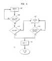
- FIG. 3is a flow diagram showing steps to set up and use a preferred embodiment speakerphone
- FIG. 4is an example of how ⁇ 2 is determined.
- FIG. 1shows an example of a preferred embodiment telephone 100 with a hands-free mode of operation that includes a first microphone 102 and a second microphone 104 being used by a speaker 106 in the presence of a noise source 108 .
- the microphones 102 , 104are identical non-directional microphones and are mounted internally to the telephone 100 and spaced as far apart as the telephone casing allows, e.g., in the two front corners of the telephone casing.
- a sound from either of speaker 106 or noise source 108arrives at each of the microphones 102 , 104 at slightly different times, normally exhibited as phase differences.
- the dual microphone speakerphoneexhibits a directional microphone characteristic when the undelayed signals from the microphones 102 , 104 are combined.
- the microphonesare external to the speakerphone casing, wired to the speakerphone.
- a larger distance between the two microphonesfacilitates suppressing the lower frequency noise sources.
- this advantageis offset in that large spacing between the two microphones 102 , 104 may result in unequal signal volume between the two microphones, especially, if the speaker is much closer to one microphone than to the other.
- this alternate embodimentmay require additional logic/circuitry to compensate for different signal volume, e.g., one amplifier, e.g., 118 as shown in FIG. 2, may have an adjustable amplification factor.
- the present inventionis described herein as a digital embodiment, this is for example only.
- the hands-free telephone of the present inventionmay be implemented using analog components without departing from the spirit or scope of the invention.
- directional microphonesmay be substituted for the above described non-directional microphones 102 , 104 , provided they are directed towards the expected speaker location and orthogonal to the line defined by the microphones.
- the distance between microphones 102 and 104is referred to herein as x 12 .
- the distance between speaker 106 and microphone 102is referred to herein as xu 1 .
- the distance between the speaker 106 and microphone 104is referred to herein as xu 2 .
- the distance between noise source 108 and microphone 102is referred to herein as xn 1 .
- the distance between noise source 108 and microphone 104is referred to as xn 2 .
- Noise originating at noise source 108 in FIG. 1arrives at microphones 102 , 104 at times offset by (xn 1 -xn 2 )/c.
- Sound from a speaker 106arrives at microphones 102 , 104 at times offset by (xu 1 -xu 2 )/c.
- ⁇ 1may be derived directly.
- a tonemay be radiated from one of the two microphones, e.g., 102 .
- the delay between when the tone originates at the first microphone 102 and when it is received at the second microphone 104is ⁇ 1 .
- FIG. 2shows a preferred embodiment hands-free mode circuit 110 for a speakerphone such as telephone 100 of FIG. 1 .
- Sound signals from one microphone 102pass through a fixed delay path that includes an input amplifier 112 , Analog-to-Digital Converter (ADC) 114 and fixed delay 116 .
- ADCAnalog-to-Digital Converter
- sound signals from the second microphone 104pass through a variable delay path that includes an input amplifier 118 , an ADC 120 and an adjustable variable delay 122 .
- the outputs of fixed delay 116 and variable delay 122are combined in adder 126 .
- the outputs of ADC 120 and fixed delay 116also are passed as inputs to Analysis and Control unit 124 .
- the output of adder 126is passed to Adjustable Digital Filter 128 .
- Analysis and Control unit 124provides control for both adjustable variable delay 122 and Adjustable Digital Filter 128 .
- Adjustable Digital Filter 128provides a digital audio output that is the audio signal passed to a listener at the other end of the call.
- Phone status signals 130are passed as inputs to Analysis and Control unit 124 .
- the amplifiers 112 , 118 of each pathact as a preamplifier to amplify the sound signal from the particular connected microphone 102 , 104 .
- the output of amplifiers 112 , 118are each passed to a respective ADC 114 , 120 .
- the ADCs 114 , 120convert the analog outputs from the corresponding amplifiers 112 , 118 to a digital output.
- the digital output signal from ADC 114is passed to a fixed delay 116 . Fixed delay 116 is set at ⁇ 1 (i.e., x 12 /C).
- the digital output from ADC 120is passed to adjustable variable delay 122 .
- the Analysis and Control unit 124may be a simple embedded processor or microcontroller (not shown) and appropriate program code, e.g., stored in a local read only memory (ROM) or electrically programmable ROM (EPROM).
- the Analysis and Control unit 124controls delay in variable delay 122 and sets the filter bandwidth of Adjustable Digital Filter 128 .
- Variable delay 122has an adjustable delay of ⁇ 2 that may be adjusted to values ranging between 0 and 2 ⁇ 1 .
- both delays 116 , 122are adjustable variable delays, having a range between 0 and ⁇ 1 .
- This alternate embodimentmaintains overall circuit delay at a minimum.
- Analysis and Control unit 124provides control to both adjustable delays.
- the signals at the two microphones 102 , 104may be added to produce a result wherein the resulting noise component varies between constructive and destructive interference, while the desired signals (xu 1 , xu 2 ) from the speaker or speakers always add constructively to provide a positive audio component.
- Analysis and Control Unit 110delays X 2 (i) between 0 and 2 ⁇ 1 , first to identify the delay to minimize noise during baseline determination and second to determine the delay to maximize xu/xn during voice spectrum analysis. Also, voice spectrum analysis results are applied to Adjustable Digital Filter 128 to enhance frequencies originating primarily from the speaker, and to dampen frequencies that originate primarily or solely from the noise source 108 . Therefore, as described hereinbelow, each of these frequency bands are identified in one of two different learning phases.
- the typical noise source spectrumis determined to identify the noise frequency bands.
- the speakerphoneis placed in hands-free mode and the composite sound that includes both noise and the speaker's voice is analyzed to determine the speaker's frequency spectrum.
- the circuitmay be calibrated to filter out noise. While it is preferred that the amplifiers 112 , 118 as well as the ADCs 114 , 120 are identical, in practice some slight differences always exist. These variations in or, differences between components in each of the paths may be compensated, preferably, during factory calibration, e.g., by adjusting the amplification factor of either or both of the amplifiers 112 , 118 . By selectively adjusting variable delay 122 it is possible to follow the speaker's voice as the speaker moves about the set of microphones 102 , 104 . This is analogous to pointing a single directional microphone automatically to the user.
- variable delay 122As the variable delay 122 is changed to compensate or to coordinate with changes of speaker location, background noise, which originates elsewhere, is dampened or, possibly, removed.
- the degree of dampening for the background noisedepends upon its angle of origin and wavelength in relation to the noise source distance from the microphones 102 , 104 , i.e., lower frequency sound (sub 100 Hz) tends to be non-directional. Since the lower the frequency (f), the longer the wavelength ( 8 ), lower frequency sound is less subject to positional filtering and dampening. However, such low frequency noise may be removed with a simple low pass filter or its equivalent in Adjustable Digital Filter 128 .
- FIG. 3is a flow diagram 140 showing set up and use of a preferred embodiment such as speakerphone 100 of FIG. 1 .
- the spacing between the microphonesis input to determine ⁇ 1 , e.g., entering the fixed delay between internal microphones 102 , 104 at the factory or, for the above described external microphone embodiment, automatically measuring the delay between origination and reception of a tone.
- the background noiseis checked. Typically, this check is done when the phone is idle such as prior to making a call, at the beginning of a conference call, etc. So, in this step 144 the phone is placed in hands free mode and silence is maintained to generate a noise baseline with any noise sources that happen to be within range of the phone.
- step 146a second learning or voice baseline step
- the speakerphoneoperates in hands-free mode and a speaker speaks from within range of the phone to obtain a voice spectrum signal.
- the Analysis and Control unit 124processes the signals from both microphones to extract the voice spectrum from the background sounds using the background noise information obtained in step 144 .
- the Adjustable Digital Filter 128is adjusted to selectively enhance speech and suppress the background sounds.
- step 148the Analysis and Control Unit 124 extracts delays both for noise sources and for voices as described hereinbelow with reference to FIG. 4 .
- step 150the optimum delay to maximize the voice to noise signal ratio (xu/xn) is set for ⁇ 2 , the adjustable variable delay 122 in the path from microphone 104 .
- the path outputs from fixed delay 116 and variable delay 122are combined in adder 126 and that sum is passed to the adjustable digital filter 128 .
- step 152the adjustable digital filter is adjusted to maximize speech and, simultaneously, suppress noise with the filtered result being passed to called parties. As long as the call continues in step 154 and while the speaker is speaking in step 156 , this variable delay calibration may be repeated, periodically, in step 148 to follow the speaker.
- step 156when the Analysis and Control Unit 110 determines that no one is speaking, noise from the noise source may be re-analyzed in step 158 and the variable delay calibration repeated in step 148 .
- the filteringends in step 160 .
- FIG. 4shows an example of how ⁇ 2 may be determined in step 148 .
- ⁇ 2is varied slightly (slightly increased/decreased) and, then, the speaker's voice to noise signal ratio (xu/xn) is checked until the optimum delay is found for ⁇ 2 , i.e., where any change in ⁇ 2 reduces xu/xn.
- Adjustable variable delay 122is then set to the optimum value of ⁇ 2 in step 150 .
- ⁇ 2⁇ 1 and xu/xn is marked or noted.
- step 1482the delay value for ⁇ 2 is increased slightly and in step 1484 , xu/xn is checked to determine if it has increased. If xu/xn increases in step 1484 an optimum value has not yet been identified and, returning to step 1482 , ⁇ 2 is increased again. Iteratively increasing ⁇ 2 and checking xu/xn in steps 1482 , 1484 continues until ⁇ 2 is maximum (2 ⁇ 1 ) or, xu/xn is not found to have increased in step 1484 . If xu/xn decreases after the first increase of ⁇ 2 in step 1482 xu/xn is not optimum.
- step 1486i.e., one increment below the current value
- step 1488⁇ 2 is backed off one increment (unless it is at its maximum value) and that value is passed to step 150 .
- step 1486If xu/xn decreases after the first increase, then the optimum value for ⁇ 2 has not been found in step 1486 . So, the optimum value lies below the current value and in step 1490 , the delay value for ⁇ 2 is decreased slightly and in step 1492 xu/xn is checked to determine if it has increased. Steps 1490 , 1492 are repeated iteratively, decreasing ⁇ 2 and checking xu/xn until ⁇ 2 is minimum (0) or xu/xn is not found to have increased in step 1492 . Again in step 1488 , ⁇ 2 is backed off one increment (unless it is at its minimum value) and that value is passed to step 150 .
- the results of the analysis in the learning steps 144 , 146are combined to automatically maximize xu/xn and provide an optimal filter for the hands free phone.
- the resultfavors voice based signals over background noise.
- the dual microphone hands free telephoneprovides a microphone characteristic that is superior to single microphone telephones, while using a non-mechanical, dynamically adjustable reception direction.
- the background and voice analysis as described for FIG. 3provides an optimal filter for the dual microphone telephone. In particular analysis is simple enough that recalibration may be done periodically, manually or automatically throughout the call to identify background noise.
- the background noisemay be analyzed while the telephone is idle or during hands free operation, if no one is speaking.
- the digital audio outputmay be provided to any typical telephone equipment, e.g., converting the filtered digital audio back to an analog signal for analog transmission or, sending it as voice over internet protocol (VoIP).
- VoIPvoice over internet protocol
- the dual microphone telephone of the present inventionprovides a significant audio quality improvement during hands free operation over prior art bands free telephones. Further, automatic recalibration may not require users to perform additional tasks or, at most, may require performing minimal additional tasks, e.g., initiating each of the learning steps.
Landscapes
- Engineering & Computer Science (AREA)
- Signal Processing (AREA)
- Telephone Function (AREA)
Abstract
Description
Claims (17)
Priority Applications (1)
| Application Number | Priority Date | Filing Date | Title |
|---|---|---|---|
| US09/994,405US6785381B2 (en) | 2001-11-27 | 2001-11-27 | Telephone having improved hands free operation audio quality and method of operation thereof |
Applications Claiming Priority (1)
| Application Number | Priority Date | Filing Date | Title |
|---|---|---|---|
| US09/994,405US6785381B2 (en) | 2001-11-27 | 2001-11-27 | Telephone having improved hands free operation audio quality and method of operation thereof |
Publications (2)
| Publication Number | Publication Date |
|---|---|
| US20030099345A1 US20030099345A1 (en) | 2003-05-29 |
| US6785381B2true US6785381B2 (en) | 2004-08-31 |
Family
ID=25540636
Family Applications (1)
| Application Number | Title | Priority Date | Filing Date |
|---|---|---|---|
| US09/994,405Expired - LifetimeUS6785381B2 (en) | 2001-11-27 | 2001-11-27 | Telephone having improved hands free operation audio quality and method of operation thereof |
Country Status (1)
| Country | Link |
|---|---|
| US (1) | US6785381B2 (en) |
Cited By (30)
| Publication number | Priority date | Publication date | Assignee | Title |
|---|---|---|---|---|
| US20070079272A1 (en)* | 2005-09-02 | 2007-04-05 | Tomoya Maekawa | Design support system and design method for circuit board, and noise analysis program |
| US20070132627A1 (en)* | 2005-12-14 | 2007-06-14 | Broadcom Corporation | Programmable settling for high speed analog to digital converter |
| US20070154031A1 (en)* | 2006-01-05 | 2007-07-05 | Audience, Inc. | System and method for utilizing inter-microphone level differences for speech enhancement |
| US20080019548A1 (en)* | 2006-01-30 | 2008-01-24 | Audience, Inc. | System and method for utilizing omni-directional microphones for speech enhancement |
| US20090058700A1 (en)* | 2005-12-14 | 2009-03-05 | Broadcom Corporation | Analog to digital converter with dynamic power configuration |
| US20090058698A1 (en)* | 2005-12-14 | 2009-03-05 | Broadcom Corporation | System and method for common mode calibration in an analog to digital converter |
| US7812746B2 (en) | 2005-12-14 | 2010-10-12 | Broadcom Corporation | Variable gain and multiplexing in a digital calibration for an analog-to-digital converter |
| US20110044474A1 (en)* | 2009-08-19 | 2011-02-24 | Avaya Inc. | System and Method for Adjusting an Audio Signal Volume Level Based on Whom is Speaking |
| US8143620B1 (en) | 2007-12-21 | 2012-03-27 | Audience, Inc. | System and method for adaptive classification of audio sources |
| US8150065B2 (en) | 2006-05-25 | 2012-04-03 | Audience, Inc. | System and method for processing an audio signal |
| US8180064B1 (en) | 2007-12-21 | 2012-05-15 | Audience, Inc. | System and method for providing voice equalization |
| US8189766B1 (en) | 2007-07-26 | 2012-05-29 | Audience, Inc. | System and method for blind subband acoustic echo cancellation postfiltering |
| US8194882B2 (en) | 2008-02-29 | 2012-06-05 | Audience, Inc. | System and method for providing single microphone noise suppression fallback |
| US8204253B1 (en) | 2008-06-30 | 2012-06-19 | Audience, Inc. | Self calibration of audio device |
| US8204252B1 (en) | 2006-10-10 | 2012-06-19 | Audience, Inc. | System and method for providing close microphone adaptive array processing |
| US8259926B1 (en) | 2007-02-23 | 2012-09-04 | Audience, Inc. | System and method for 2-channel and 3-channel acoustic echo cancellation |
| US8355511B2 (en) | 2008-03-18 | 2013-01-15 | Audience, Inc. | System and method for envelope-based acoustic echo cancellation |
| US8521530B1 (en) | 2008-06-30 | 2013-08-27 | Audience, Inc. | System and method for enhancing a monaural audio signal |
| US8744844B2 (en) | 2007-07-06 | 2014-06-03 | Audience, Inc. | System and method for adaptive intelligent noise suppression |
| US8774423B1 (en) | 2008-06-30 | 2014-07-08 | Audience, Inc. | System and method for controlling adaptivity of signal modification using a phantom coefficient |
| US8849231B1 (en) | 2007-08-08 | 2014-09-30 | Audience, Inc. | System and method for adaptive power control |
| CN104104346A (en)* | 2014-07-14 | 2014-10-15 | 深圳市中兴移动通信有限公司 | Method and device for improving audio playing effect of mobile terminal |
| US8934641B2 (en) | 2006-05-25 | 2015-01-13 | Audience, Inc. | Systems and methods for reconstructing decomposed audio signals |
| US8949120B1 (en) | 2006-05-25 | 2015-02-03 | Audience, Inc. | Adaptive noise cancelation |
| US9008329B1 (en) | 2010-01-26 | 2015-04-14 | Audience, Inc. | Noise reduction using multi-feature cluster tracker |
| US9185487B2 (en) | 2006-01-30 | 2015-11-10 | Audience, Inc. | System and method for providing noise suppression utilizing null processing noise subtraction |
| US9536540B2 (en) | 2013-07-19 | 2017-01-03 | Knowles Electronics, Llc | Speech signal separation and synthesis based on auditory scene analysis and speech modeling |
| US9640194B1 (en) | 2012-10-04 | 2017-05-02 | Knowles Electronics, Llc | Noise suppression for speech processing based on machine-learning mask estimation |
| US9699554B1 (en) | 2010-04-21 | 2017-07-04 | Knowles Electronics, Llc | Adaptive signal equalization |
| US9799330B2 (en) | 2014-08-28 | 2017-10-24 | Knowles Electronics, Llc | Multi-sourced noise suppression |
Families Citing this family (5)
| Publication number | Priority date | Publication date | Assignee | Title |
|---|---|---|---|---|
| DE10330286B4 (en)* | 2003-07-04 | 2005-08-18 | Infineon Technologies Ag | Method and apparatus for transmitting voice signals over a communications network |
| DE102009029367B4 (en)* | 2009-09-11 | 2012-01-12 | Dietmar Ruwisch | Method and device for analyzing and adjusting the acoustic properties of a hands-free car kit |
| CN103501375B (en) | 2013-09-16 | 2017-04-19 | 华为终端有限公司 | Method and device for controlling sound effect |
| CN105282339B (en)* | 2015-10-30 | 2019-04-12 | 东莞酷派软件技术有限公司 | A kind of method, device and mobile terminal monitoring Mike's working condition |
| CN105450880B (en)* | 2015-11-12 | 2018-01-26 | 广东欧珀移动通信有限公司 | A voice signal processing method and device |
Citations (5)
| Publication number | Priority date | Publication date | Assignee | Title |
|---|---|---|---|---|
| US5471538A (en)* | 1992-05-08 | 1995-11-28 | Sony Corporation | Microphone apparatus |
| US5953380A (en)* | 1996-06-14 | 1999-09-14 | Nec Corporation | Noise canceling method and apparatus therefor |
| US20010028720A1 (en)* | 2000-02-17 | 2001-10-11 | Zezhang Hou | Null adaptation in multi-microphone directional system |
| US20020031234A1 (en)* | 2000-06-28 | 2002-03-14 | Wenger Matthew P. | Microphone system for in-car audio pickup |
| US6549627B1 (en)* | 1998-01-30 | 2003-04-15 | Telefonaktiebolaget Lm Ericsson | Generating calibration signals for an adaptive beamformer |
Family Cites Families (7)
| Publication number | Priority date | Publication date | Assignee | Title |
|---|---|---|---|---|
| US5029207A (en)* | 1990-02-01 | 1991-07-02 | Scientific-Atlanta, Inc. | External security module for a television signal decoder |
| JPH09507729A (en)* | 1994-01-13 | 1997-08-05 | バンカーズ・トラスト・カンパニー | Cryptographic system and method with key escrow function |
| US5999629A (en)* | 1995-10-31 | 1999-12-07 | Lucent Technologies Inc. | Data encryption security module |
| FR2751154B1 (en)* | 1996-07-15 | 1998-09-11 | Schlumberger Ind Sa | INFORMATION DIVERSIFICATION SYSTEM IN A PRODUCT OR SERVICE DISTRIBUTION NETWORK |
| US6363482B1 (en)* | 1997-09-08 | 2002-03-26 | Harmonic Data Systems, Ltd. | Secure broadband communication |
| US6996720B1 (en)* | 1999-12-17 | 2006-02-07 | Microsoft Corporation | System and method for accessing protected content in a rights-management architecture |
| US20040203354A1 (en)* | 2002-06-29 | 2004-10-14 | Lin Yue | Bluetooth remote access device |
- 2001
- 2001-11-27USUS09/994,405patent/US6785381B2/ennot_activeExpired - Lifetime
Patent Citations (5)
| Publication number | Priority date | Publication date | Assignee | Title |
|---|---|---|---|---|
| US5471538A (en)* | 1992-05-08 | 1995-11-28 | Sony Corporation | Microphone apparatus |
| US5953380A (en)* | 1996-06-14 | 1999-09-14 | Nec Corporation | Noise canceling method and apparatus therefor |
| US6549627B1 (en)* | 1998-01-30 | 2003-04-15 | Telefonaktiebolaget Lm Ericsson | Generating calibration signals for an adaptive beamformer |
| US20010028720A1 (en)* | 2000-02-17 | 2001-10-11 | Zezhang Hou | Null adaptation in multi-microphone directional system |
| US20020031234A1 (en)* | 2000-06-28 | 2002-03-14 | Wenger Matthew P. | Microphone system for in-car audio pickup |
Cited By (47)
| Publication number | Priority date | Publication date | Assignee | Title |
|---|---|---|---|---|
| US7647034B2 (en)* | 2005-09-02 | 2010-01-12 | Panasonic Corporation | Design support system and design method for circuit board, and noise analysis program |
| US20070079272A1 (en)* | 2005-09-02 | 2007-04-05 | Tomoya Maekawa | Design support system and design method for circuit board, and noise analysis program |
| US7928874B2 (en) | 2005-12-14 | 2011-04-19 | Broadcom Corporation | Analog to digital converter with dynamic power configuration |
| US7812746B2 (en) | 2005-12-14 | 2010-10-12 | Broadcom Corporation | Variable gain and multiplexing in a digital calibration for an analog-to-digital converter |
| US20090058700A1 (en)* | 2005-12-14 | 2009-03-05 | Broadcom Corporation | Analog to digital converter with dynamic power configuration |
| US20090058698A1 (en)* | 2005-12-14 | 2009-03-05 | Broadcom Corporation | System and method for common mode calibration in an analog to digital converter |
| US20090058699A1 (en)* | 2005-12-14 | 2009-03-05 | Broadcom Corporation | Programmable settling for high speed analog to digital converter |
| US8179293B2 (en) | 2005-12-14 | 2012-05-15 | Broadcom Corporation | Programmable settling for high speed analog to digital converter |
| US7812747B2 (en) | 2005-12-14 | 2010-10-12 | Broadcom Corporation | System and method for common mode calibration in an analog to digital converter |
| US7817072B2 (en) | 2005-12-14 | 2010-10-19 | Broadcom Corporation | Analog to digital converter with dynamic power configuration |
| US20070132627A1 (en)* | 2005-12-14 | 2007-06-14 | Broadcom Corporation | Programmable settling for high speed analog to digital converter |
| US7843370B2 (en)* | 2005-12-14 | 2010-11-30 | Broadcom Corporation | Programmable settling for high speed analog to digital converter |
| US7843368B2 (en) | 2005-12-14 | 2010-11-30 | Broadcom Corporation | Programmable settling for high speed analog to digital converter |
| US20110032131A1 (en)* | 2005-12-14 | 2011-02-10 | Broadcom Corporation | Analog To Digital Converter with Dynamic Power Configuration |
| US20110068962A1 (en)* | 2005-12-14 | 2011-03-24 | Broadcom Corporation | Programmable Settling for High Speed Analog to Digital Converter |
| US8867759B2 (en) | 2006-01-05 | 2014-10-21 | Audience, Inc. | System and method for utilizing inter-microphone level differences for speech enhancement |
| US8345890B2 (en) | 2006-01-05 | 2013-01-01 | Audience, Inc. | System and method for utilizing inter-microphone level differences for speech enhancement |
| US20070154031A1 (en)* | 2006-01-05 | 2007-07-05 | Audience, Inc. | System and method for utilizing inter-microphone level differences for speech enhancement |
| US9185487B2 (en) | 2006-01-30 | 2015-11-10 | Audience, Inc. | System and method for providing noise suppression utilizing null processing noise subtraction |
| US20080019548A1 (en)* | 2006-01-30 | 2008-01-24 | Audience, Inc. | System and method for utilizing omni-directional microphones for speech enhancement |
| US8194880B2 (en) | 2006-01-30 | 2012-06-05 | Audience, Inc. | System and method for utilizing omni-directional microphones for speech enhancement |
| US8150065B2 (en) | 2006-05-25 | 2012-04-03 | Audience, Inc. | System and method for processing an audio signal |
| US8934641B2 (en) | 2006-05-25 | 2015-01-13 | Audience, Inc. | Systems and methods for reconstructing decomposed audio signals |
| US8949120B1 (en) | 2006-05-25 | 2015-02-03 | Audience, Inc. | Adaptive noise cancelation |
| US9830899B1 (en) | 2006-05-25 | 2017-11-28 | Knowles Electronics, Llc | Adaptive noise cancellation |
| US8204252B1 (en) | 2006-10-10 | 2012-06-19 | Audience, Inc. | System and method for providing close microphone adaptive array processing |
| US8259926B1 (en) | 2007-02-23 | 2012-09-04 | Audience, Inc. | System and method for 2-channel and 3-channel acoustic echo cancellation |
| US8744844B2 (en) | 2007-07-06 | 2014-06-03 | Audience, Inc. | System and method for adaptive intelligent noise suppression |
| US8886525B2 (en) | 2007-07-06 | 2014-11-11 | Audience, Inc. | System and method for adaptive intelligent noise suppression |
| US8189766B1 (en) | 2007-07-26 | 2012-05-29 | Audience, Inc. | System and method for blind subband acoustic echo cancellation postfiltering |
| US8849231B1 (en) | 2007-08-08 | 2014-09-30 | Audience, Inc. | System and method for adaptive power control |
| US8143620B1 (en) | 2007-12-21 | 2012-03-27 | Audience, Inc. | System and method for adaptive classification of audio sources |
| US9076456B1 (en) | 2007-12-21 | 2015-07-07 | Audience, Inc. | System and method for providing voice equalization |
| US8180064B1 (en) | 2007-12-21 | 2012-05-15 | Audience, Inc. | System and method for providing voice equalization |
| US8194882B2 (en) | 2008-02-29 | 2012-06-05 | Audience, Inc. | System and method for providing single microphone noise suppression fallback |
| US8355511B2 (en) | 2008-03-18 | 2013-01-15 | Audience, Inc. | System and method for envelope-based acoustic echo cancellation |
| US8774423B1 (en) | 2008-06-30 | 2014-07-08 | Audience, Inc. | System and method for controlling adaptivity of signal modification using a phantom coefficient |
| US8521530B1 (en) | 2008-06-30 | 2013-08-27 | Audience, Inc. | System and method for enhancing a monaural audio signal |
| US8204253B1 (en) | 2008-06-30 | 2012-06-19 | Audience, Inc. | Self calibration of audio device |
| US20110044474A1 (en)* | 2009-08-19 | 2011-02-24 | Avaya Inc. | System and Method for Adjusting an Audio Signal Volume Level Based on Whom is Speaking |
| US9008329B1 (en) | 2010-01-26 | 2015-04-14 | Audience, Inc. | Noise reduction using multi-feature cluster tracker |
| US9699554B1 (en) | 2010-04-21 | 2017-07-04 | Knowles Electronics, Llc | Adaptive signal equalization |
| US9640194B1 (en) | 2012-10-04 | 2017-05-02 | Knowles Electronics, Llc | Noise suppression for speech processing based on machine-learning mask estimation |
| US9536540B2 (en) | 2013-07-19 | 2017-01-03 | Knowles Electronics, Llc | Speech signal separation and synthesis based on auditory scene analysis and speech modeling |
| CN104104346A (en)* | 2014-07-14 | 2014-10-15 | 深圳市中兴移动通信有限公司 | Method and device for improving audio playing effect of mobile terminal |
| CN104104346B (en)* | 2014-07-14 | 2019-06-28 | 努比亚技术有限公司 | A kind of method and apparatus improving mobile terminal playing audio |
| US9799330B2 (en) | 2014-08-28 | 2017-10-24 | Knowles Electronics, Llc | Multi-sourced noise suppression |
Also Published As
| Publication number | Publication date |
|---|---|
| US20030099345A1 (en) | 2003-05-29 |
Similar Documents
| Publication | Publication Date | Title |
|---|---|---|
| US6785381B2 (en) | Telephone having improved hands free operation audio quality and method of operation thereof | |
| CA2560034C (en) | System for selectively extracting components of an audio input signal | |
| CN100397781C (en) | sound enhancement system | |
| KR101311028B1 (en) | Intelligibility control using ambient noise detection | |
| US7263373B2 (en) | Sound-based proximity detector | |
| US8379884B2 (en) | Sound signal transmitter-receiver | |
| US20090253418A1 (en) | System for conference call and corresponding devices, method and program products | |
| US8218777B2 (en) | Multipoint communication apparatus | |
| US6741873B1 (en) | Background noise adaptable speaker phone for use in a mobile communication device | |
| US20030204397A1 (en) | Method of compensating for beamformer steering delay during handsfree speech recognition | |
| JP2002534849A (en) | Method and apparatus for adaptive signal gain control in a communication system | |
| US10516941B2 (en) | Reducing instantaneous wind noise | |
| JPH08163227A (en) | Automatic received sound volume varying circuit | |
| KR100857822B1 (en) | A method for automatically adjusting the output signal level according to the ambient noise signal level in a voice communication device and a voice communication device therefor | |
| KR100742140B1 (en) | Method and apparatus for automatically adjusting mobile phone speaker and microphone gain | |
| JP2009171208A (en) | Automatic volume control device and voice communication device using the same | |
| US7760869B2 (en) | Method and apparatus for controlling the transmit volume level of a speakerphone | |
| CN101263705B (en) | Sound pick-up method and device, in particular for hands-free telephone terminals | |
| US7327840B2 (en) | Loudspeaker telephone equalization method and equalizer for loudspeaker telephone | |
| JP2007258951A (en) | Teleconference equipment | |
| US20110134911A1 (en) | Selective filtering for digital transmission when analogue speech has to be recreated | |
| US20200304925A1 (en) | Hearing aid | |
| CN114446315A (en) | Communication device and method for adjusting output side tone | |
| JP2008022182A (en) | Telephone set | |
| JPH1023114A (en) | Telephone set |
Legal Events
| Date | Code | Title | Description |
|---|---|---|---|
| AS | Assignment | Owner name:SIEMENS INFORMATION AND COMMUNICATION NETWORKS, IN Free format text:ASSIGNMENT OF ASSIGNORS INTEREST;ASSIGNOR:GARTNER, MARTIN;REEL/FRAME:012329/0058 Effective date:20011112 Owner name:SIEMENS INFORMATION AND COMMUNICATION NETWORKS, IN Free format text:ASSIGNMENT OF ASSIGNORS INTEREST;ASSIGNOR:SLAGLE, THOMAS;REEL/FRAME:012329/0120 Effective date:20011112 | |
| STCF | Information on status: patent grant | Free format text:PATENTED CASE | |
| FPAY | Fee payment | Year of fee payment:4 | |
| AS | Assignment | Owner name:SIEMENS COMMUNICATIONS, INC.,FLORIDA Free format text:MERGER;ASSIGNOR:SIEMENS INFORMATION AND COMMUNICATION NETWORKS, INC.;REEL/FRAME:024263/0817 Effective date:20040922 Owner name:SIEMENS COMMUNICATIONS, INC., FLORIDA Free format text:MERGER;ASSIGNOR:SIEMENS INFORMATION AND COMMUNICATION NETWORKS, INC.;REEL/FRAME:024263/0817 Effective date:20040922 | |
| AS | Assignment | Owner name:SIEMENS ENTERPRISE COMMUNICATIONS, INC.,FLORIDA Free format text:ASSIGNMENT OF ASSIGNORS INTEREST;ASSIGNOR:SIEMENS COMMUNICATIONS, INC.;REEL/FRAME:024294/0040 Effective date:20100304 Owner name:SIEMENS ENTERPRISE COMMUNICATIONS, INC., FLORIDA Free format text:ASSIGNMENT OF ASSIGNORS INTEREST;ASSIGNOR:SIEMENS COMMUNICATIONS, INC.;REEL/FRAME:024294/0040 Effective date:20100304 | |
| AS | Assignment | Owner name:WELLS FARGO TRUST CORPORATION LIMITED, AS SECURITY Free format text:GRANT OF SECURITY INTEREST IN U.S. PATENTS;ASSIGNOR:SIEMENS ENTERPRISE COMMUNICATIONS, INC.;REEL/FRAME:025339/0904 Effective date:20101109 | |
| FPAY | Fee payment | Year of fee payment:8 | |
| AS | Assignment | Owner name:ENTERPRISE TECHNOLOGIES S.A.R.L., LUXEMBOURG Free format text:ASSIGNMENT OF ASSIGNORS INTEREST;ASSIGNORS:SIEMENS ENTERPRISE COMMUNICATIONS, INC.;SIEMENS ENTERPRISE COMMUNICATIONS GMBH & CO. KG;REEL/FRAME:030224/0375 Effective date:20130411 | |
| AS | Assignment | Owner name:ENTERPRISE SYSTEMS TECHNOLOGIES S.A.R.L., LUXEMBOU Free format text:ASSIGNMENT OF ASSIGNORS INTEREST;ASSIGNOR:ENTERPRISE TECHNOLOGIES S.A.R.L.;REEL/FRAME:030231/0039 Effective date:20130415 | |
| AS | Assignment | Owner name:SIEMENS ENTERPRISE COMMUNICATIONS INC., FLORIDA Free format text:RELEASE BY SECURED PARTY;ASSIGNOR:WELLS FARGO TRUST CORPORATION LIMITED;REEL/FRAME:037472/0736 Effective date:20130405 | |
| FPAY | Fee payment | Year of fee payment:12 |