US6784637B2 - Battery charger/tester with storage media - Google Patents
Battery charger/tester with storage mediaDownload PDFInfo
- Publication number
- US6784637B2 US6784637B2US10/235,704US23570402AUS6784637B2US 6784637 B2US6784637 B2US 6784637B2US 23570402 AUS23570402 AUS 23570402AUS 6784637 B2US6784637 B2US 6784637B2
- Authority
- US
- United States
- Prior art keywords
- battery
- charger
- charging
- data
- removable
- Prior art date
- Legal status (The legal status is an assumption and is not a legal conclusion. Google has not performed a legal analysis and makes no representation as to the accuracy of the status listed.)
- Expired - Lifetime
Links
Images


Classifications
- G—PHYSICS
- G01—MEASURING; TESTING
- G01R—MEASURING ELECTRIC VARIABLES; MEASURING MAGNETIC VARIABLES
- G01R31/00—Arrangements for testing electric properties; Arrangements for locating electric faults; Arrangements for electrical testing characterised by what is being tested not provided for elsewhere
- G01R31/36—Arrangements for testing, measuring or monitoring the electrical condition of accumulators or electric batteries, e.g. capacity or state of charge [SoC]
- G01R31/3644—Constructional arrangements
- G01R31/3648—Constructional arrangements comprising digital calculation means, e.g. for performing an algorithm
- H—ELECTRICITY
- H02—GENERATION; CONVERSION OR DISTRIBUTION OF ELECTRIC POWER
- H02J—CIRCUIT ARRANGEMENTS OR SYSTEMS FOR SUPPLYING OR DISTRIBUTING ELECTRIC POWER; SYSTEMS FOR STORING ELECTRIC ENERGY
- H02J7/00—Circuit arrangements for charging or depolarising batteries or for supplying loads from batteries
- H02J7/00032—Circuit arrangements for charging or depolarising batteries or for supplying loads from batteries characterised by data exchange
- H02J7/00036—Charger exchanging data with battery
- H—ELECTRICITY
- H02—GENERATION; CONVERSION OR DISTRIBUTION OF ELECTRIC POWER
- H02J—CIRCUIT ARRANGEMENTS OR SYSTEMS FOR SUPPLYING OR DISTRIBUTING ELECTRIC POWER; SYSTEMS FOR STORING ELECTRIC ENERGY
- H02J7/00—Circuit arrangements for charging or depolarising batteries or for supplying loads from batteries
- H02J7/00047—Circuit arrangements for charging or depolarising batteries or for supplying loads from batteries with provisions for charging different types of batteries
Definitions
- Embodiments of the present inventiongenerally relate to a power source charger and tester. More particularly, the present invention relates to an apparatus and method that allows data to be stored and retrieved on a battery charger/tester.
- Rechargeable batteriesare an important source of clean portable power in a wide variety of electrical applications, including automobiles, boats and electric vehicles.
- Lead-acid batteriesare one form of rechargeable battery that are commonly used to start engines, propel electric vehicles, and to act as a source of back-up power when an external supply of electricity is interrupted. While not particularly energy efficient, due to the weight of lead in comparison to other metals, the technology of lead-acid batteries is mature. As a result, the batteries are cheap, reliable, and readily produced and thus, continue to constitute a substantial portion of the rechargeable batteries being produced today.
- lead-acid batteriesto deliver large amounts of electrical power is well known, particularly when associated with the starting and powering of motor vehicles. Because the lead-acid batteries can be depleted of power overtime, such as when they are not in use over a period of time, or when a light in a car is left on for an extended period of time, they need to be recharged and tested. A number of battery testers and chargers have thus been developed to charge and test the lead-acid battery.
- Most conventional battery charger/testerare equipped to provide multiple charging rates for charging different size batteries.
- the multiple charging ratesare achieved by varying the charging voltage at the battery terminals, generally by changing the transformer primary/secondary winding ratio.
- An operatormanually selects the rate at which the battery should be charged and also the duration of the charge cycle if the charger is equipped with a timer function.
- conventional battery chargerscan also include testers with the appropriate gauges in order to determine the current state of charge in a battery, how long and at what rate a particular battery should be charged, whether it is safe to charge the battery, and whether the battery is capable of accepting a charge.
- the operatormust return to check the status of the battery to ensure that the battery is charging properly. Because conventional battery requires actual visual inspection of the gauges, the operator can waste valuable time and money to inspect all the batteries that are currently being charged instead of generating money by working on other projects.
- temperature of the batteryis an indicator as to how successfully the battery is accepting the charge.
- Different batteriesaccept the charge in a number of different ways. For example, some batteries heat up beyond a normal range. Anything beyond this normal range is an indication that the battery is not accepting the charge in an efficient manner.
- a battery charger/testerto include a temperature sensing device, which monitors the device throughout the entire processing charging and testing process. There is a further need to provide the collected temperature data back to the charger to enable it to adjust the charge/test rate of the battery based upon this data.
- Embodiments of the present inventiongenerally provide for a battery charger/tester having a storage media.
- the battery charger/testercan store information and retrieve information from the storage media.
- a charging apparatusthat can include a power source charger having a module port, and a removable data module received in the module port and is in communication with the power source charger.
- the power source chargercan include a tester.
- the power source chargercan also include a controller that is in communication with the removable data module.
- the controllercan store data and retrieve data on the removable data module.
- the removable data modulecan be selected from a group that can include a floppy disc, a tape drive cartridge, an optical media, a flash memory, a magnetic based media, a magneto optical, a hard drive, any other removable media and a combination thereof.
- the removable data module's datacan be selected from a group that can include the result of the charging/testing of the battery, the battery's warranty information, the battery type, the battery brand, the battery model, previous information regarding charging/testing of the battery, firmware update, diagnostic or operating parameters information of the charger, maintenance information of the charger, any other data required by the operator, and a combination thereof.
- a method of storing and retrieving data for a charging apparatuscan include operating the charging apparatus, and accessing a removable data module by a microprocessor.
- the charging apparatuscan further include a tester. Operating the charging apparatus can be charging and testing the battery. Accessing the removable data module can be storing data resulting from operating the battery charger and can be retrieving previously stored data.
- the removable data modulecan be selected from a group that can include a floppy disc, a tape drive cartridge, an optical media, a flash memory, a magnetic based media, a magneto optical, a hard drive, any other removable media, and a combination thereof.
- a charging systemthat can include a power source charger means having a module receiving means, and a removable data means that can be received in the module receiving means and is in communication with the power source charger means.
- the power source charger meanscan further include a power source testing means.
- the power source charger meanscan include a controller means that is in communication with the removable data means.
- the controller meanscan control and store data onto the removable data means.
- the controller meanscan also control and retrieve data from the removable data means.
- the removable data meanscan be selected from that can include a floppy disc, a tape drive cartridge, an optical media, a flash memory, a magnetic based media, a magneto optical, a hard drive, any other removable media, and a combination thereof.
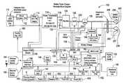
- FIG. 1is a hardware block diagram of an embodiment of the current invention.
- FIG. 2is a hardware block diagram.
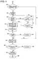
- FIG. 4is a flowchart of the process for testing and charging partially charged batteries in accordance with a preferred embodiment of the present invention.
- FIG. 5is a flowchart of the process for testing and charging discharged batteries in accordance with a preferred embodiment of the present invention.
- FIG. 6is a front view of a display and keyboard of one embodiment of the current invention.
- FIG. 1is an embodiment of the current invention.
- the battery charger/tester 100(“charger 100 ”) can include a power source 110 that provides a 120V (volts) AC (alternating current) to the charger 100 .
- a circuit breaker 112is provided to prevent damage that can be caused by a sudden power surge or a short in the system.
- a power switch 114is linked to the power source 110 to enable the operator to turn the charger 100 on or off.
- a power transformer 116is provided to step down both the voltage and current to a level that enables the charger 100 to charge and/or test a battery.
- the power source 110supplies the charger 100 with 120V AC.
- the power transformer 116reduces the 120V AC to approximately 20-25V AC, which is optimal for charging the battery.
- Two lines 118 , 120 from the power transformer 116are inputted into a rectifier 124 and a third line 122 is directly coupled to the negative clamp 238 .
- the lines 118 , 120pulse alternately through a full-wave rectifier 124 at a cycle of 60 Hz.
- the diodes of the rectifier 124convert the positive AC voltage to DC (direct current) power supply.
- the third line 122provides a return path for the negative voltage of outputs 118 , 120 to return to the transformer 116 .
- a silicon control rectifier (SCR) 126 or thyristoris included in the preferred embodiment to regulate the output from the rectifier 124 to the battery. Exiting from the rectifier 124 is a pulsed positive sine waveform with peak voltages and current. The sine waveform results in varying voltages and current being outputted from the rectifier 124 .
- the SCR 126essentially operates as a switch allowing certain voltages and/or current to pass to the battery.
- the operatorcan choose either a voltage or a current or both to charge the battery. This selection is called a set-point.
- This set-pointis then transmitted to a FPGA 142 (field programmable gate array, discussed below), which then determines at which point in the sine wave to allow voltage to pass through to the battery.
- This point in the sine waveis related to the set-point as chosen by the operator.
- the set-pointdepending on the selection of the operator, is situated on the sine wave by starting from the end of the sine wave and working in a rearward direction. Once the set-point is located on the sine wave, the voltage underneath the sine wave is allowed to pass through. Therefore, the set-point voltage is a mean value of a range of voltages.
- this set-point of 12Vis entered into the charger 100 .
- the set-pointis transmitted to the FPGA 142 , which then determines at which point in the sine wave to allow the voltage or current to pass through to the battery.
- the 12V set-point in this examplepermits voltages larger than and less than 12V to pass through to the battery.
- the mean of the voltages distributed to the batterywill approximately equal twelve volts.
- the SCR 126operates essentially as a switch and allows current or voltage to pass to the battery at a set-point fixed by the operator.
- the SCR 126can operate based on either voltage, current or a combination thereof.
- the SCR 126is normally switched off until it receives a signal from an I/O control (input/output) 134 .
- the voltage or current exiting from the rectifier 124is transmitted to an ADC (analog-to-digital converter) 136 .
- the ADC 136transmits the voltage or current information to a linked CPLD (computer programmable logic device) 140 , which is linked to the FPGA 142 .
- CPLDcomputer programmable logic device
- the FPGA 142determines the operability of the SCR 126 by comparing the previously programmed set-point value with the output value of the rectifier 124 . If the output value of the rectifier 124 is equal or greater than the set-point of the SCR 126 , then the FPGA 142 instructs the I/O control 134 to send a signal to the SCR 126 to allow the output voltage or current to pass to the battery. For example, if the operator desires a minimum current of 20 amps, the SCR 126 will allow a current equal to or exceeding 20 amps to pass to the battery.
- a current sensor 128is provided at the output of the SCR 126 to monitor or sense the current exiting from the rectifier 124 and the SCR 126 .
- the current from the rectifier 124is relayed to the ADC 136 , which like the voltage is fed to the CPLD 140 and then onto the FPGA 142 .
- the FPGA 142verifies if the current from the rectifier 124 is equal to or exceeds the current set-point value.
- the output from the current sensor 128is connected to the battery clamps 238 , 240 .
- FIG. 2illustrates a battery tester charger 200 according to one embodiment of the invention.
- a battery 202 having a positive terminal 234 and a negative terminal 236may be attached to the battery tester charger 200 via a positive clamp 240 and a negative clamp 238 located at an end of the respective positive and negative cables 230 , 232 .
- the battery tester charger 200can determine whether the connections between the battery 202 and the clamps 238 , 240 are acceptable.
- a connection testmay be performed at either the positive 240 or the negative clamp 238 connection by applying the connection test to the positive components 230 , 240 or negative components 232 , 238 of the battery tester charger 200 .
- applying the connection test to both componentswill test both the positive and negative connections.
- the connection testmay be performed by comparing the voltage in the battery cables 230 , 232 upstream from the connection of the clamps 238 , 240 , and the voltage at the connection of the clamps 238 , 240 .
- Voltage loss due to cable resistances 208 , 210may be considered and subtracted from the difference in voltage at the clamps 238 , 240 and the upstream position. Additional differences in voltage between the upstream position and the connections of the clamps 238 , 240 may be caused by clamp connection resistances 206 , 204 .
- the testing of the battery connectionscan be applied to either the positive or negative components to test the connections individually or can be applied to both components to test both connections.
- the external battery cables 230 , 232are attached to the respective terminals 234 , 236 of the battery 202 via the respective clamps 240 , 238 .
- Standard clampssuch as alligator clamps, may be used.
- a portion 237 , 239 (FIG. 1) of each clamp 238 , 240is isolated from the remainder of the clamps 238 , 240 and the associated cables 232 , 230 .
- Portions 237 , 239can be isolated from the remainder of the clamps 238 , 240 by a non-conductive element.
- the cables 232 , 230can carry a large current, either to the battery 202 when charging or from the battery when the battery is in use.
- the isolated portions 237 , 239may be connected to another device to determine the voltage at terminals 234 , 236 .
- the isolated portions 237 , 239may be attached to high impedance wires 226 , 224 to differential operational amplifiers 214 , 212 (opp. amp) as shown in FIG. 2 .
- the high impedance wires 226 , 224may be attached to the ADC 136 .
- the battery connectionsmay be tested to determine the resistances 206 , 204 associated with the connection when the battery 202 is charged by a current source 110 or exposed to a heavy load 144 . Whether the battery 202 is charging or in use, large current will flow through the cables 230 , 232 and clamps 240 , 238 .
- a sensor 220 , 222 in the battery charger tester 200senses the voltage upstream from the clamps 240 , 238 and the battery terminals 234 , 236 connections and inputs a signal representative of the voltage to opp amps 214 , 212 or optionally to the ADC 136 .
- the voltagemay be sensed upstream from the current sense 128 in both cables 230 , 232 as shown in FIG. 1 .
- voltageis sensed in the isolated portions 237 , 239 and compared to the voltage sensed upstream.
- the cable resistances 208 , 210are known, and the portion of the voltage difference between the voltage in the isolated portions 237 , 239 and the voltage at the upstream position is accounted for by the cable resistances 208 , 210 .
- the remaining voltage difference between the voltage measured at the isolated portions 237 , 239 and the upstream positionsis due to the resistances in the clamps 240 , 238 and terminal 234 , 236 connections.
- cable resistances 208 , 210 and the associated difference in voltage due to cable resistances 208 , 210may be neglected or approximated.
- the unknown connection resistances 206 , 204 associated with the connectioncan be expressed in terms of known parameters of current and voltage, thus the resistances 206 , 204 can be determined.
- connection resistances 206 , 204can be evaluated to determine whether the connection is acceptable or not.
- a methodis provided and compares the connection resistances 206 , 204 against a predetermined acceptable and non-acceptable range of connection resistance. Based on the comparison, the operator can determine whether the connection is acceptable or not.
- a methodis provided to compare the voltage differences between the isolated portions 237 , 239 and the voltage in the cables 230 , 232 at the upstream positions. If the difference in voltage between the two locations is negligible, then the connection is likely to be acceptable. Optionally, the difference in voltage due to cable resistances 208 , 210 may be subtracted from the voltage difference or otherwise accounted for in determining whether the connections are acceptable or not. If the voltage difference is higher than a predetermined maximum amount, then the connection between the battery terminal 234 and the clamp 140 will likely be unacceptable.
- the battery tester charger 200can alert or notify the operator. In some embodiments, the battery tester charger 200 may alert the operator as to which connection (positive or negative) is unacceptable or whether both are unacceptable. In some embodiments, the battery tester charger 200 may alert the operator that the connection(s) are acceptable. The operator may be alerted by a variety of ways, such as an indicator light, a message on a display screen, an audible signal, or other ways that are disclosed herein. Because the operator is warned that a connection is not acceptable, the operator may take corrective measures to improve the connection, such as cleaning or replacing the terminals 234 , 236 or clamps 240 , 238 .
- a Sabre Battery Test procedureis used as a heavy load test to analyze the condition of the battery.
- the heavy load testis applied with a heavy load 144 that includes a solenoid switch 146 .
- the solenoid switch 146is operated by the FPGA 142 through the I/O control 134 via the CPLD 140 .
- the solenoid switch 146 in the heavy load testensures that a high load amperage test can be efficiently and safely transmitted to the battery.
- One detraction in incorporating the solenoid switch 146 with the heavy load testis that it is not possible to make an exact determination of when the heavy load 144 is started or ended.
- the preferred embodimentanalyzes the charge-state of a given type of battery, determines whether the battery is defective and, if not, charges the battery at its most optimum charge rate up to its maximum allowed charging volts. Furthermore, the preferred embodiment executes its analysis, determination, and charging in the safest and most optimal time possible.
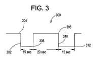
- the heavy load testis shown in the Sabre Test Timing Diagram 300 in FIG. 3 .
- the Sabre Battery Testrequires a first applied load 302 to be placed on an open circuit 304 .
- a battery voltage reading (“LVA15”) 306can be taken at the end of the first applied load 302 , which is approximately fifteen seconds after the first load 302 is applied and released.
- a bounce back voltage measurement (“Rv”) 308is taken approximately twenty seconds after the first applied load 302 is turned off.
- a second applied load 310is then placed on the open circuit 304 and maintained for approximately fifteen seconds.
- Another battery voltage reading (“LVB15”) 312is taken at the end of the second applied load 310 .
- Heavy load testsare highly accurate for testing charged batteries. If the battery to be tested is partially charged, then the test accurately determines whether the battery is defective. A person skilled in the art will recognize that any heavy load test procedure that is suitable for testing the condition of the battery may be used. Additionally, load as used herein can also be a charge.
- a preferred embodiment of the inventioncan calculate a set time to charge the battery. If LVB15 312 is less than 4.0 V, the set time, i.e., maximum charge time, equals approximately forty-five minutes. If LVB15 312 is equal to or greater than 4.0 V, the set charge time is calculated as follows:
- Vss12.5V if Rv>12.5 V
- Vss11.7V if Rv ⁇ 11.7 V
- the charger 100calculates the state of charge of the battery and the set time required to charge the battery while maintaining an optimum charge rate.
- the charger 100controls the optimum charge rate by precisely controlling the charging voltage throughout the charging cycle.
- the battery conditioncan be charged, as determined by the heavy load test (e.g., Sabre Battery Test), further testing and charging will be performed. If the battery condition is determined to be faulty, then testing is terminated and the battery can be discarded. Therefore, the operator does not waste time and effort to charge the defective battery.
- the heavy load teste.g., Sabre Battery Test
- the first step in this testingis to determine whether the bounce back voltage is greater than 12.6 volts 400 .
- the bounce back voltageis a measure of the state of battery charge. If the bounce back voltage is determined to be greater than 12.6 volts, the battery tester/charger will perform a micro-load test 162 . If the bounce back voltage is equal to or less than 12.6 volts, the charger 100 is activated 402 to charge the battery for a set time 404 .
- the charger 100While the battery is being charged 402 , the current is monitored. If the charge is greater than five amps 406 , the charger 100 continues to charge for the set time. If the current is less than or equal to five amps 406 , the charger 100 continues to charge the battery for a minimum of at least five minutes 408 .
- the charger 100turns off 410 .
- a heavy load testis applied to the battery for at least ten seconds followed by the heavy load 144 being removed for at least twenty seconds 410 .
- the previous application and removal of the heavy load 144is important to condition the battery by stabilizing the battery voltage.
- Another heavy load test 412is then performed on the battery.
- the charger 100determines from the heavy load test 412 if the battery is good 414 . If the battery is determined to be faulty or bad 416 , the testing is terminated and the battery is discarded. If the battery is determined to be functional 414 , or if the bounce back voltage is greater than 12.6 volts, the cold cranking amps (“CCA”) are measured using a micro-load test 418 .
- CCAcold cranking amps
- the micro-load test 418is performed after the battery is determined to be functional by the heavy load test 412 .
- This micro-load test 418is performed by applying a smaller load (approximately twenty to sixty amps) for a preset duration (approximately 250 milliseconds to one second) and measuring the CCA 420 after the micro-load 162 is removed. If the measured CCA is greater than 70% of the rated CCA 420 of the battery, then the battery is good and the charge is completed 424 , then the cycle ends at 426 . If the measured CCA is less than 70% of the rated CCA 420 of the battery, then it is bad battery 422 and will be discarded. It should be recognized that other micro-load tests could be substituted for the micro-load test 418 described above. For example, a dual micro-load test can also be used.
- the charger 100will charge the battery and retest it in accordance with the method depicted in FIG. 5 .
- the charger 100is activated 500 .
- the charger 100charges the battery for approximately one-minute 502 .
- the battery voltageis read after one-minute 504 . If the battery voltage 504 is less than one volt after one minute, the battery is bad.
- the charger 100is then turned off and the battery will be discarded 506 .
- the charger 100will continue to charge for approximately nine minutes 508 . During the nine minutes of charging, the charging current is recorded or read at one-minute intervals to determine if the charging current exceeds three amps 510 . If the charging current is equal to or does not exceed three amps, the battery is determined to be bad 512 and the charger 100 is turned off and the battery is discarded.
- the charger 100will continue to charge for the set period of time as calculated above 514 .
- the charger 100will apply the heavy load 144 to the battery for a period of ten seconds to condition the battery and then removed the heavy load for a period of twenty seconds 516 for the battery voltage to stabilize.
- the heavy load test(e.g., Sabre Battery Test) is then performed 518 .
- the charger 100determines whether the battery is good 520 . If the battery is determined to be bad 522 , it is discarded. If the battery is determined to be functional 520 , the CCA is then measured using the micro-load test 524 . The measured CCA is then compared to the rated CCA for the battery 526 . In the preferred embodiment of the invention, if the measured CCA is less than or equal to approximately seventy percent of the rated CCA for the battery 526 , then the battery is determined to be bad 528 and is discarded. If the measured CCA 526 is greater than approximately seventy percent of the CCA, then the battery is determined to be good 530 and the charge is completed 532 .
- the preferred embodimentcontains an infrared temperature sensor 164 , which aids in monitoring both the charger 100 and the battery being charged.
- the infrared temperature sensor 164ensures that both the battery and charger 100 are maintained are safe levels.
- the infrared sensor 164is contained within a housing. The housing is placed over the charging battery for safety reasons especially in the instance that, while charging, the battery unexpectedly explodes. The housing aids in containing the surrounding areas from the contaminants of the exploded battery.
- the infrared temperature sensor 164is placed within the housing to monitor the temperature of a charging battery. While charging a battery, heat is discharged or dissipated from the battery. However, excessive heat is an indication that the battery is being charged at an excessive rate.
- the infrared temperature sensor 164is linked to the ADC 136 , essentially an input to the ADC 136 , which relays the information to the CPLD 140 , which then relays it to the FPGA 142 .
- the FPGA 142with the help of the infrared temperature sensor 164 , can monitor the temperature of the battery and relay the information, including any problems to the operator.
- the infrared temperature sensor 164is aimed at the battery to ensure that the temperature of the battery is being monitored throughout the charging process. For example, if the battery being charged contains a short, the battery will heat excessively in a short period of time. The feedback from the infrared temperature sensor 164 can be used to alert the operator of the problem so that the operator can take the appropriate action.
- a gel batterycan heat excessively during charging and therefore, the charging current is applied in relation to the heat detected.
- a temperatureis fixed after which point the charging current is reduced.
- the charging timeis reduced.
- the temperature and charging currentare proportionally related in specific types of batteries (e.g. gel).
- the gel battery or other batteriescan be charged efficiently, and explosions can be prevented during charging.
- the infrared temperature sensor 164can be aimed at the charger 100 only or in combination with the battery. By monitoring the charger 100 , any excessive temperature generated by the charger can be relayed to the operator, thus appropriate actions can be taken to avoid overheating and damaging the charger.
- the temperature sensor 164can be located in a number of different locations, either located in the charger 100 or linked to the charger 100 .
- the location of the infrared temperature sensor 164is not limited to a housing. Additionally, temperature sensors are needed most when the battery is charging. Therefore, monitoring the temperature of the battery and/or the charger can help to prevent battery explosions.
- a conventional processoris replaced by a dynamic FPGA 142 .
- the use of the FPGA 142allows a designer to make changes to the charger 100 without having to replace the processor. Changes to a mounted conventional processor requires remounting and reconfiguration of the charger 100 design, which in turn requires more design hours. With the use of the FPGA 142 , the designer is allowed to make changes and additional costs on the fly without remounting or grasp reconfiguration of the initial design.
- the FPGA 142is configured and arranged to operate as a conventional processor. In the preferred embodiment the FPGA 142 control and processes a number of different functions of the charger 100 . One such function is the operation of the micro and heavy load tests 418 , 412 . These tests are downloaded and stored into a memory device 144 . It can also be stored in a RAM device 146 . Once stored in these memory devices 144 , 146 , the code is downloaded into the FPGA 142 and executed. Upon execution of the code, the FPGA 142 begins to operate various controls of the charger 100 , such as the solenoid switch 146 on the heavy load 144 , and the SCR 126 for current and voltage control.
- various controls of the charger 100such as the solenoid switch 146 on the heavy load 144 , and the SCR 126 for current and voltage control.
- datacan be inputted into the FPGA 142 through the input device 148 , such as a keypad.
- the FPGA 142can transmit to and receive information from an output display 150 , a serial port 154 , such as a printer port, a second serial port 152 , such as an infrared bar code reader, a module port 156 that can accept various communication modules, or any other device that can communicate with the FPGA.
- an image of a soft-core microprocessoris loaded from the memory (i.e. flash 144 , RAM 146 , etc.) into the FPGA 142 . Therefore, there is an image of the FPGA 142 resides in the memory. Additionally, upon start-up, the CPLD 140 takes control of the data and address bus and clocks the FPGA 142 image from memory into the FPGA 142 . As stated previously, this allows for redesign of the processor and the board without the need for remounting a processor. All that is necessary for a design change is to upload a new FPGA image into the memory device. Additionally, any new tests or operating parameters that is required by the operator can be easily upload into the FPGA 142 and executed. The preferred embodiment uses flash memory 144 to accomplish this function.
- the output display 150can be an integrated display or a remote display that relays information, such as data gathered from the charging and testing of the battery, and menu information. Additionally, the display 150 can notify the operator of any problems that have been detected.
- the serial port 154 in the preferred embodimentare standard RS-232 serial ports for connecting a device such as a printer.
- RS-232can be replaced with an RS-432, an infrared serial port or a wireless radio frequency port, such as BLUETOOTHTM, or any other similar device.
- a bar code port 152is provided.
- the bar code port 152may serve to operably connect a bar code reader (not shown) to the FPGA 142 or a microprocessor.
- the bar code port 152may be a conventional component, such as an RS-232.
- the bar code readermay be, for example, a conventional optical bar code reader, such as a gun or a wand type reader.
- the bar codeitself may be affixed to the battery at the time of manufacture, purchase, or service.
- the bar codemay contain information, or point to information stored in a database.
- the databasemay be located within the FPGA 142 , the storage media 168 (below) or located remotely and accessed electronically. Examples of remotely located databases include data based accessible by the Internet, Ethernet, or other remote memory storage facility.
- the bar codemay provide a variety of information regarding the battery.
- the bar codemay provide information regarding the battery type (e.g. gel, flooded lead acid, deep cycle), the battery rating (cold cranking amps), maintenance information, serial number, lot number, warranty information, and a manufacture date code. This data can be used to select parameters for the test or charge cycle.
- the data provided by the bar codeis not limited to the examples given.
- the printer port 154may print bar code labels that may be attached or otherwise associated with the battery and provide updated information.
- the updated informationmay include, among other things, service dates, service procedures, and warranty information (e.g. time left on warranty, who was the original purchaser, what types of service are and are not warranted, etc.)
- warranty informatione.g. time left on warranty, who was the original purchaser, what types of service are and are not warranted, etc.
- the printed labelmay then be read by the bar code reader in subsequent tests or charge cycles.
- the output display 150 and an input device 148are illustrated in a preferred embodiment in FIG. 6 .
- the display 150 and input device 148can be located preferably on a common face of a cabinet of the charger 100 , although they alternatively can be located remote from each other and/or remote from the cabinet of the charger, if desired.
- the display 150can include one or more LED's indicating states of the charger 100 or the battery during charging or testing. For example, LED 652 indicates that power is applied to the unit, LED 653 indicates a charge is being applied to the battery, LED 654 indicates a fault in the battery, and LED 655 indicates a good battery is detected.
- a segmented or dot matrix type, alphanumeric LCD display 656may also be provided as part of the output display 150 .
- the display 656can be a 4 by 20 backlit LCD display, having four rows each having twenty character columns. This permits display of a wide range of information relating to e.g., charging status, time, amount, etc, as well as display and selection from a menu of control functions.
- the display 150can include either the alphanumeric display 656 , the LED's 652 to 655 or both. The two types of displays can be on a single panel or separate ones.
- Control functionsmay be inputted via at least one, preferably two and more preferably three or more functional buttons, such as up down buttons 658 , and a menu select button 660 .
- a ten key alphanumeric keypad 662may also or alternatively be provided for input of numeric data, alphabetic data, and/or command selection. Each key can provide for entry of a number, one or more letters, and/or a function.
- the input device 151can include the menu button 660 , the up down buttons 658 , the alphanumeric keypad 662 , or a combination thereof. These arrangements can be on a single panel or separate ones.
- the key labeled GOmay generally be used in the affirmative. It usually means continue on. It is also used to initiate menu prompts leading to the test/charge sequence.
- the key labeled CLEARcan generally be used in the negative. It is generally used to clear a value that is to be entered. It may also be used to break out of a process or back out of a menu sequence.
- the key labeled MENUcan be used to initiate the function menu. It is also used to back out of a menu sequence.
- the ARROW KEYScan be used to navigate within the menus and display screens. If an arrow is displayed on the right of the display, the corresponding arrow key can be used to “move” the view to another part of the menu or screen.
- the arrow keysmay also be used to increment or decrement a displayed value.
- the NUMBER KEYScan be used to communicate with the application in a number of ways. They can be used to indicate the selection on a menu. They can also be used to provide numerical and/or alphabetical input to an application parameter.
- the screenmay include the ability to scroll through a set of menu items, such as for example, the following:
- This menuis by way of example only. Other features, commands, displays or inputs, for example may also be provided.
- an additional smaller transformer 158provides current and voltage to the I/O control 134 and a cooling fan 160 .
- the smaller transformer 158provides a step down of both the voltage and current to a level that enables the I/O control 134 and a cooling fan 160 to operate.
- the cooling fan 160helps to control the operating temperature of the charger 100 .
- the peripheral module port 156can be constructed and arranged to receive an information relay device, such as an Ethernet wired module 166 and/or an Ethernet wireless module 164 .
- the Ethernet modules 164 , 166communicate at data rates of 10 Mbps (10Base-T Ethernet), 100 Mbps (Fast Ethernet), 1000 Mbps (Gigabit Ethernet), and other data rates.
- the Ethernet modules 164 , 166can relay information between the charger 100 and another device connected to the modules via a wire or wirelessly.
- the information relayedcan include data from the result of the charging/testing of the battery, data of the battery's warranty information, data of the battery type (deep cycle, gel, etc.), data of battery make and model, data from previous charging/testing of the battery, firmware update, data from diagnostic or operating parameters of the charger 100 , maintenance data of the charger 100 , and any other data required by the operator.
- the peripheral module port 156is in communication with the FPGA 142 .
- Informationcan be exchanged between the peripheral module port 156 , the Ethernet modules 164 , 166 , and the FPGA 142 .
- the Ethernet modules 164 , 166can relay the information to and from a remote device, such as a network server, a printer, a personal computer, a workstation, a file server, a print server, other communication devices, such as a fax machine, a cellular/digital phone, a pager, a personal digital assistant, an email receiver, and a display.
- a remote devicesuch as a network server, a printer, a personal computer, a workstation, a file server, a print server, other communication devices, such as a fax machine, a cellular/digital phone, a pager, a personal digital assistant, an email receiver, and a display.
- a printer serversuch as a printer server, a printer, a personal computer, a workstation, a
- Ethernet module 164 , 166information can also be stored remotely, such as on a workstation, a file server or other data storage device.
- the information from the test/chargecan be relayed and stored on a networked personal computer.
- the information stored on the networked personal computerthe information from any previous charge/test can be compared with the latest information, a report can be generated and forwarded to the appropriate personnel.
- the chargers 100(same or similar model) that are used by the operator are “networked” together, the chargers' firmware can be updated simultaneously.
- update firmwarea laptop is hooked up to the charger 100 and the new firmware is uploaded. Once the upload is completed, the operator then must go to the next charger 100 and repeat the process until all of the chargers 100 are updated with the new firmware.
- the update processwill be less time consuming, and thus cost-effective for the operator.
- the chargers 100 networked via the Ethernet modules 164 , 166information from all the chargers 100 can be relayed and displayed to the operator.
- the chargers 100can be networked, the operator does not have check each individual charger 100 to see if the charging and testing is completed and save valuable time and money. Additionally, by being networked, the chargers 100 can be instructed to run diagnostics and other functions remotely without having to individually program each charger 100 .
- a notification systemis provided to notify the operator when there is a problem with the charger 100 or the battery or when the charging/testing is completed.
- the operatorhas to physically check the status of the charger 100 and often would have to return many times to see if the charging/testing is completed.
- the status informationcan be relayed to a remote location, such as the network server or the personal computer, which can be programmed to notify the operator of any problems or the completion of the charging/testing. Because the operator can be notified of any problems, the operator can take appropriate measures, such as terminating the charging of the battery because charger 100 or the battery is overheating.
- Notification of the operatorcan be done with a personal computer that can notify the operator via another display, by pager, by fax, by email, by phone, by computer or by any means that will relay the requested information to the operator.
- the peripheral module port 156can be constructed and arranged to accept a removable data storage media 168 (“storage media”). Information can be exchanged between the peripheral module port 156 , the storage media 168 , and the FPGA 142 .
- the storage media 168can be permanently fixed to the charger 100 to provide additional memory or can be removable, as required by the operator.
- the storage media 168can transfer information to and from the charger 100 .
- the informationcan include data from the result of the charging/testing of the battery, the battery's warranty information, the battery type (deep cycle, gel, etc.), battery make and model, data from previous charging/testing of the battery, firmware update, data from diagnostic or operating parameters of the charger 100 , maintenance data of the charger 100 , and any other data required by the operator.
- the storage media 168can include, but not limited to floppy disc (including ZIP); tape drive cartridge (such as DAT); optical media (such as CD-ROM, DVD-ROM, etc.); flash memory (such as smart media, compact flash, PC card memory, memory sticks, flash SIMMs and DIMMS, etc.); magnetic based media, magneto optical; USB drives; or any other storage media that an operator can store or retrieve information from it.
- floppy discincluding ZIP
- tape drive cartridgesuch as DAT
- optical mediasuch as CD-ROM, DVD-ROM, etc.
- flash memorysuch as smart media, compact flash, PC card memory, memory sticks, flash SIMMs and DIMMS, etc.
- magnetic based mediamagneto optical
- USB drivesor any other storage media that an operator can store or retrieve information from it.
- any storage mediacan be used.
- One use of the storage media 168is to update firmware, wherein the storage media can be programmed with the firmware update and loaded into the charger 100 .
- the operatorcan select the “update firmware” option from a menu that was previously provided to the charger 100 .
- the charger 100is able to retrieve the new firmware and update the charger 100 .
- the operatorcan use the storage media 168 to store information regarding the battery that was charged/tested. The information can be downloaded into the storage media 168 , such as a compact flash card, and can be sent to the appropriate person.
- the storage media 168can contain information from the charging/testing result of a battery at another location and can be uploaded into the charger 100 and displayed to the operator.
- the informationcan be relayed via the Ethernet module to be viewed, stored, or printed at a remote location.
- the storage media 168can also provide an image of a soft-core microprocessor to the FPGA 142 during start-up. By having the storage media 168 , the files relating to information, the results from previous tests charges, can be easily matched up to the battery and electronic files are stored in less space than their equivalent amount in paper files.
- the charger 100can have more than one peripheral module port 156 so that a communication nodule, a storage media module, and an many other modules as needed can be onboard the charger.
- the peripheral module port 156provides flexibility to the charger 100 and provides a port so that any new device can be added to the charger as needed by the operator.
Landscapes
- Engineering & Computer Science (AREA)
- Power Engineering (AREA)
- Physics & Mathematics (AREA)
- General Physics & Mathematics (AREA)
- Charge And Discharge Circuits For Batteries Or The Like (AREA)
- Secondary Cells (AREA)
Abstract
Description
Claims (17)
Priority Applications (1)
| Application Number | Priority Date | Filing Date | Title |
|---|---|---|---|
| US10/235,704US6784637B2 (en) | 2002-06-27 | 2002-09-06 | Battery charger/tester with storage media |
Applications Claiming Priority (2)
| Application Number | Priority Date | Filing Date | Title |
|---|---|---|---|
| US39162002P | 2002-06-27 | 2002-06-27 | |
| US10/235,704US6784637B2 (en) | 2002-06-27 | 2002-09-06 | Battery charger/tester with storage media |
Publications (2)
| Publication Number | Publication Date |
|---|---|
| US20040000891A1 US20040000891A1 (en) | 2004-01-01 |
| US6784637B2true US6784637B2 (en) | 2004-08-31 |
Family
ID=30770881
Family Applications (1)
| Application Number | Title | Priority Date | Filing Date |
|---|---|---|---|
| US10/235,704Expired - LifetimeUS6784637B2 (en) | 2002-06-27 | 2002-09-06 | Battery charger/tester with storage media |
Country Status (2)
| Country | Link |
|---|---|
| US (1) | US6784637B2 (en) |
| CA (1) | CA2433545C (en) |
Cited By (81)
| Publication number | Priority date | Publication date | Assignee | Title |
|---|---|---|---|---|
| US6850037B2 (en) | 1997-11-03 | 2005-02-01 | Midtronics, Inc. | In-vehicle battery monitor |
| US7034541B2 (en) | 2001-10-17 | 2006-04-25 | Midtronics, Inc. | Query based electronic battery tester |
| US7126341B2 (en) | 1997-11-03 | 2006-10-24 | Midtronics, Inc. | Automotive vehicle electrical system diagnostic device |
| US20070001647A1 (en)* | 2004-04-02 | 2007-01-04 | Awelco Inc. S.P.A. | Device for measuring a battery energy, in particular during charge/discharge of a battery |
| US20070028020A1 (en)* | 2005-03-30 | 2007-02-01 | David Elder | Tamper resistant battery and battery warranty and performance tracking system |
| US20070229032A1 (en)* | 2006-07-14 | 2007-10-04 | David Elder | Battery monitoring, warranty, and performance tracking system |
| US20070278990A1 (en)* | 2006-06-06 | 2007-12-06 | Spx Corporation | Battery boosting apparatus and method |
| US7398176B2 (en) | 2000-03-27 | 2008-07-08 | Midtronics, Inc. | Battery testers with secondary functionality |
| US7408358B2 (en) | 2003-06-16 | 2008-08-05 | Midtronics, Inc. | Electronic battery tester having a user interface to configure a printer |
| US7498767B2 (en) | 2005-02-16 | 2009-03-03 | Midtronics, Inc. | Centralized data storage of condition of a storage battery at its point of sale |
| US7505856B2 (en) | 1999-04-08 | 2009-03-17 | Midtronics, Inc. | Battery test module |
| US7545146B2 (en) | 2004-12-09 | 2009-06-09 | Midtronics, Inc. | Apparatus and method for predicting battery capacity and fitness for service from a battery dynamic parameter and a recovery voltage differential |
| US7557586B1 (en) | 1999-11-01 | 2009-07-07 | Midtronics, Inc. | Electronic battery tester |
| US7595643B2 (en) | 2003-11-11 | 2009-09-29 | Midtronics, Inc. | Apparatus and method for simulating a battery tester with a fixed resistance load |
| US7598744B2 (en) | 2000-03-27 | 2009-10-06 | Midtronics, Inc. | Scan tool for electronic battery tester |
| US7598743B2 (en) | 2000-03-27 | 2009-10-06 | Midtronics, Inc. | Battery maintenance device having databus connection |
| US7619417B2 (en) | 2002-12-31 | 2009-11-17 | Midtronics, Inc. | Battery monitoring system |
| US20090284228A1 (en)* | 2008-05-19 | 2009-11-19 | Ajith Kuttannair Kumar | System and method for providing hybrid energy on a marine vessel |
| US7642786B2 (en) | 2004-06-01 | 2010-01-05 | Midtronics, Inc. | Battery tester capable of identifying faulty battery post adapters |
| US7706991B2 (en) | 1996-07-29 | 2010-04-27 | Midtronics, Inc. | Alternator tester |
| US7705602B2 (en) | 1997-11-03 | 2010-04-27 | Midtronics, Inc. | Automotive vehicle electrical system diagnostic device |
| US7710119B2 (en) | 2004-12-09 | 2010-05-04 | Midtronics, Inc. | Battery tester that calculates its own reference values |
| US7728597B2 (en) | 2000-03-27 | 2010-06-01 | Midtronics, Inc. | Electronic battery tester with databus |
| US7772850B2 (en) | 2004-07-12 | 2010-08-10 | Midtronics, Inc. | Wireless battery tester with information encryption means |
| US7774151B2 (en) | 1997-11-03 | 2010-08-10 | Midtronics, Inc. | Wireless battery monitor |
| US7777612B2 (en) | 2004-04-13 | 2010-08-17 | Midtronics, Inc. | Theft prevention device for automotive vehicle service centers |
| US7791348B2 (en) | 2007-02-27 | 2010-09-07 | Midtronics, Inc. | Battery tester with promotion feature to promote use of the battery tester by providing the user with codes having redeemable value |
| US7808375B2 (en) | 2007-04-16 | 2010-10-05 | Midtronics, Inc. | Battery run down indicator |
| US7928698B2 (en) | 2008-03-25 | 2011-04-19 | Spx Corporation | Battery charging apparatus and method |
| US7977914B2 (en) | 2003-10-08 | 2011-07-12 | Midtronics, Inc. | Battery maintenance tool with probe light |
| US8164343B2 (en) | 2003-09-05 | 2012-04-24 | Midtronics, Inc. | Method and apparatus for measuring a parameter of a vehicle electrical system |
| US8203345B2 (en) | 2007-12-06 | 2012-06-19 | Midtronics, Inc. | Storage battery and battery tester |
| US8306690B2 (en) | 2007-07-17 | 2012-11-06 | Midtronics, Inc. | Battery tester for electric vehicle |
| CN102771028A (en)* | 2009-10-21 | 2012-11-07 | 微电子股份有限公司 | Patches for battery-interfacing devices and associated systems and methods |
| US8344685B2 (en) | 2004-08-20 | 2013-01-01 | Midtronics, Inc. | System for automatically gathering battery information |
| US8436619B2 (en) | 2004-08-20 | 2013-05-07 | Midtronics, Inc. | Integrated tag reader and environment sensor |
| US8442877B2 (en) | 2004-08-20 | 2013-05-14 | Midtronics, Inc. | Simplification of inventory management |
| US8513949B2 (en) | 2000-03-27 | 2013-08-20 | Midtronics, Inc. | Electronic battery tester or charger with databus connection |
| US8674711B2 (en) | 2003-09-05 | 2014-03-18 | Midtronics, Inc. | Method and apparatus for measuring a parameter of a vehicle electrical system |
| US8738309B2 (en) | 2010-09-30 | 2014-05-27 | Midtronics, Inc. | Battery pack maintenance for electric vehicles |
| US8872517B2 (en) | 1996-07-29 | 2014-10-28 | Midtronics, Inc. | Electronic battery tester with battery age input |
| US8958998B2 (en) | 1997-11-03 | 2015-02-17 | Midtronics, Inc. | Electronic battery tester with network communication |
| US9018958B2 (en) | 2003-09-05 | 2015-04-28 | Midtronics, Inc. | Method and apparatus for measuring a parameter of a vehicle electrical system |
| US20150318727A1 (en)* | 2012-11-20 | 2015-11-05 | Robert Bosch Gmbh | Device for testing and maintaining a high voltage battery and uses thereof |
| US9201120B2 (en) | 2010-08-12 | 2015-12-01 | Midtronics, Inc. | Electronic battery tester for testing storage battery |
| US9229062B2 (en) | 2010-05-27 | 2016-01-05 | Midtronics, Inc. | Electronic storage battery diagnostic system |
| US9244100B2 (en) | 2013-03-15 | 2016-01-26 | Midtronics, Inc. | Current clamp with jaw closure detection |
| US9255955B2 (en) | 2003-09-05 | 2016-02-09 | Midtronics, Inc. | Method and apparatus for measuring a parameter of a vehicle electrical system |
| US9274157B2 (en) | 2007-07-17 | 2016-03-01 | Midtronics, Inc. | Battery tester for electric vehicle |
| US9312575B2 (en) | 2013-05-16 | 2016-04-12 | Midtronics, Inc. | Battery testing system and method |
| US9419311B2 (en) | 2010-06-18 | 2016-08-16 | Midtronics, Inc. | Battery maintenance device with thermal buffer |
| US9425487B2 (en) | 2010-03-03 | 2016-08-23 | Midtronics, Inc. | Monitor for front terminal batteries |
| US9496720B2 (en) | 2004-08-20 | 2016-11-15 | Midtronics, Inc. | System for automatically gathering battery information |
| US9588185B2 (en) | 2010-02-25 | 2017-03-07 | Keith S. Champlin | Method and apparatus for detecting cell deterioration in an electrochemical cell or battery |
| US20170194798A1 (en)* | 2016-01-05 | 2017-07-06 | Guangdong Oppo Mobile Telecommunications Corp., Ltd. | Quick charging method, mobile terminal, and power adapter |
| US9851411B2 (en) | 2012-06-28 | 2017-12-26 | Keith S. Champlin | Suppressing HF cable oscillations during dynamic measurements of cells and batteries |
| US9923289B2 (en) | 2014-01-16 | 2018-03-20 | Midtronics, Inc. | Battery clamp with endoskeleton design |
| US9966676B2 (en) | 2015-09-28 | 2018-05-08 | Midtronics, Inc. | Kelvin connector adapter for storage battery |
| US10046649B2 (en) | 2012-06-28 | 2018-08-14 | Midtronics, Inc. | Hybrid and electric vehicle battery pack maintenance device |
| US10222397B2 (en) | 2014-09-26 | 2019-03-05 | Midtronics, Inc. | Cable connector for electronic battery tester |
| US10317468B2 (en) | 2015-01-26 | 2019-06-11 | Midtronics, Inc. | Alternator tester |
| US10429449B2 (en) | 2011-11-10 | 2019-10-01 | Midtronics, Inc. | Battery pack tester |
| US10473555B2 (en) | 2014-07-14 | 2019-11-12 | Midtronics, Inc. | Automotive maintenance system |
| US10608353B2 (en) | 2016-06-28 | 2020-03-31 | Midtronics, Inc. | Battery clamp |
| US10843574B2 (en) | 2013-12-12 | 2020-11-24 | Midtronics, Inc. | Calibration and programming of in-vehicle battery sensors |
| US11054480B2 (en) | 2016-10-25 | 2021-07-06 | Midtronics, Inc. | Electrical load for electronic battery tester and electronic battery tester including such electrical load |
| US11325479B2 (en) | 2012-06-28 | 2022-05-10 | Midtronics, Inc. | Hybrid and electric vehicle battery maintenance device |
| US11474153B2 (en) | 2019-11-12 | 2022-10-18 | Midtronics, Inc. | Battery pack maintenance system |
| US11486930B2 (en) | 2020-01-23 | 2022-11-01 | Midtronics, Inc. | Electronic battery tester with battery clamp storage holsters |
| US11513160B2 (en) | 2018-11-29 | 2022-11-29 | Midtronics, Inc. | Vehicle battery maintenance device |
| US11545839B2 (en) | 2019-11-05 | 2023-01-03 | Midtronics, Inc. | System for charging a series of connected batteries |
| US11566972B2 (en) | 2019-07-31 | 2023-01-31 | Midtronics, Inc. | Tire tread gauge using visual indicator |
| US11650259B2 (en) | 2010-06-03 | 2023-05-16 | Midtronics, Inc. | Battery pack maintenance for electric vehicle |
| US11668779B2 (en) | 2019-11-11 | 2023-06-06 | Midtronics, Inc. | Hybrid and electric vehicle battery pack maintenance device |
| US11740294B2 (en) | 2010-06-03 | 2023-08-29 | Midtronics, Inc. | High use battery pack maintenance |
| US20230344261A1 (en)* | 2019-10-09 | 2023-10-26 | The Noco Company | Battery charging device for charging a deeply discharged battery, and battery charging system and method |
| US11973202B2 (en) | 2019-12-31 | 2024-04-30 | Midtronics, Inc. | Intelligent module interface for battery maintenance device |
| US12237482B2 (en) | 2019-12-31 | 2025-02-25 | Midtronics, Inc. | Intelligent module interface for battery maintenance device |
| US12320857B2 (en) | 2016-10-25 | 2025-06-03 | Midtronics, Inc. | Electrical load for electronic battery tester and electronic battery tester including such electrical load |
| US12330513B2 (en) | 2022-02-14 | 2025-06-17 | Midtronics, Inc. | Battery maintenance device with high voltage connector |
| US12392833B2 (en) | 2022-05-09 | 2025-08-19 | Midtronics, Inc. | Electronic battery tester |
Families Citing this family (35)
| Publication number | Priority date | Publication date | Assignee | Title |
|---|---|---|---|---|
| US7246015B2 (en) | 1996-07-29 | 2007-07-17 | Midtronics, Inc. | Alternator tester |
| US20030088375A1 (en)* | 2001-10-17 | 2003-05-08 | Bertness Kevin I. | Electronic battery tester with relative test output |
| US6914413B2 (en)* | 1996-07-29 | 2005-07-05 | Midtronics, Inc. | Alternator tester with encoded output |
| US8198900B2 (en)* | 1996-07-29 | 2012-06-12 | Midtronics, Inc. | Automotive battery charging system tester |
| US6885195B2 (en)* | 1996-07-29 | 2005-04-26 | Midtronics, Inc. | Method and apparatus for auditing a battery test |
| US7003410B2 (en)* | 1996-07-29 | 2006-02-21 | Midtronics, Inc. | Electronic battery tester with relative test output |
| US6331762B1 (en)* | 1997-11-03 | 2001-12-18 | Midtronics, Inc. | Energy management system for automotive vehicle |
| US7688074B2 (en)* | 1997-11-03 | 2010-03-30 | Midtronics, Inc. | Energy management system for automotive vehicle |
| US6871151B2 (en) | 1997-11-03 | 2005-03-22 | Midtronics, Inc. | Electronic battery tester with network communication |
| US6930485B2 (en)* | 2002-03-14 | 2005-08-16 | Midtronics, Inc. | Electronic battery tester with battery failure temperature determination |
| AU4333000A (en) | 1999-04-08 | 2000-11-14 | Midtronics, Inc. | Electronic battery tester |
| US6759849B2 (en) | 2000-03-27 | 2004-07-06 | Kevin I. Bertness | Battery tester configured to receive a removable digital module |
| US6967484B2 (en) | 2000-03-27 | 2005-11-22 | Midtronics, Inc. | Electronic battery tester with automotive scan tool communication |
| SE524561C2 (en)* | 2000-04-25 | 2004-08-24 | Intra Internat Ab | Current measurement circuit with two measuring ranges |
| US20040113494A1 (en)* | 2000-09-01 | 2004-06-17 | Karuppana Samy V. | Daytime running light control using an intelligent power management system |
| US6906523B2 (en)* | 2000-09-14 | 2005-06-14 | Midtronics, Inc. | Method and apparatus for testing cells and batteries embedded in series/parallel systems |
| US7501795B2 (en)* | 2001-06-22 | 2009-03-10 | Midtronics Inc. | Battery charger with booster pack |
| US7479763B2 (en) | 2001-06-22 | 2009-01-20 | Midtronics, Inc. | Apparatus and method for counteracting self discharge in a storage battery |
| US20080150542A1 (en)* | 2003-02-13 | 2008-06-26 | William Sapp | Battery analyzer in a battery pack and fixture |
| US6891378B2 (en)* | 2003-03-25 | 2005-05-10 | Midtronics, Inc. | Electronic battery tester |
| US6913483B2 (en)* | 2003-06-23 | 2005-07-05 | Midtronics, Inc. | Cable for electronic battery tester |
| US7319304B2 (en)* | 2003-07-25 | 2008-01-15 | Midtronics, Inc. | Shunt connection to a PCB of an energy management system employed in an automotive vehicle |
| US7598699B2 (en)* | 2004-02-20 | 2009-10-06 | Midtronics, Inc. | Replaceable clamp for electronic battery tester |
| US20050206346A1 (en)* | 2004-03-18 | 2005-09-22 | Midtronics, Inc. | Battery charger with automatic customer notification system |
| US7119686B2 (en)* | 2004-04-13 | 2006-10-10 | Midtronics, Inc. | Theft prevention device for automotive vehicle service centers |
| US7106070B2 (en)* | 2004-07-22 | 2006-09-12 | Midtronics, Inc. | Broad-band low-inductance cables for making Kelvin connections to electrochemical cells and batteries |
| US20080084187A1 (en)* | 2006-10-04 | 2008-04-10 | Powercart Systems Inc. | Mobile Power Supply |
| US20090047572A1 (en)* | 2007-08-16 | 2009-02-19 | Micropower Electronics, Inc. | Controlled pressure release for packaged batteries and associated systems and methods |
| US7959476B2 (en)* | 2008-06-16 | 2011-06-14 | Midtronics, Inc. | Clamp for electrically coupling to a battery contact |
| US9608460B2 (en)* | 2009-07-30 | 2017-03-28 | Aerovironment, Inc. | Remote rechargeable monitoring system and method |
| US9667074B2 (en)* | 2014-03-28 | 2017-05-30 | Symbol Technologies, Llc | Apparatus and method for updating remote standalone firmware |
| CN106786871A (en)* | 2016-12-19 | 2017-05-31 | 北京小米移动软件有限公司 | Charge control method, apparatus and system |
| CN112636848B (en)* | 2020-12-22 | 2022-12-13 | 上海微波技术研究所(中国电子科技集团公司第五十研究所) | Hand-held radio comprehensive tester and testing method thereof |
| CN114383793A (en)* | 2021-12-03 | 2022-04-22 | 上海氢晨新能源科技有限公司 | A device and method suitable for air tightness detection, purging and chamber volume measurement of fuel cells |
| CN117148090B (en)* | 2023-10-27 | 2024-01-26 | 深圳市鲁光电子科技有限公司 | Testing device for gallium nitride device |
Citations (5)
| Publication number | Priority date | Publication date | Assignee | Title |
|---|---|---|---|---|
| US4423378A (en) | 1981-12-04 | 1983-12-27 | Bear Automotive Service Equipment Company | Automotive battery test apparatus |
| US5049804A (en)* | 1987-06-01 | 1991-09-17 | Power-Tech Systems Corporation | Universal battery charging system and a method |
| US5583416A (en) | 1994-01-26 | 1996-12-10 | Gnb Battery Technologies, Inc. | Apparatus and method for step-charging batteries to optimize charge acceptance |
| US5831435A (en)* | 1997-04-16 | 1998-11-03 | Midtronics, Inc. | Battery tester for JIS Standard |
| US6037778A (en) | 1997-11-05 | 2000-03-14 | Stat Engineering Company, L.L.C. | Electronic battery testing device and method for testing batteries |
- 2002
- 2002-09-06USUS10/235,704patent/US6784637B2/ennot_activeExpired - Lifetime
- 2003
- 2003-06-26CACA002433545Apatent/CA2433545C/ennot_activeExpired - Fee Related
Patent Citations (6)
| Publication number | Priority date | Publication date | Assignee | Title |
|---|---|---|---|---|
| US4423378A (en) | 1981-12-04 | 1983-12-27 | Bear Automotive Service Equipment Company | Automotive battery test apparatus |
| US5049804A (en)* | 1987-06-01 | 1991-09-17 | Power-Tech Systems Corporation | Universal battery charging system and a method |
| US5583416A (en) | 1994-01-26 | 1996-12-10 | Gnb Battery Technologies, Inc. | Apparatus and method for step-charging batteries to optimize charge acceptance |
| US5589757A (en) | 1994-01-26 | 1996-12-31 | Gnb Battery Technologies, Inc. | Apparatus and method for step-charging batteries to optimize charge acceptance |
| US5831435A (en)* | 1997-04-16 | 1998-11-03 | Midtronics, Inc. | Battery tester for JIS Standard |
| US6037778A (en) | 1997-11-05 | 2000-03-14 | Stat Engineering Company, L.L.C. | Electronic battery testing device and method for testing batteries |
Cited By (106)
| Publication number | Priority date | Publication date | Assignee | Title |
|---|---|---|---|---|
| US8872517B2 (en) | 1996-07-29 | 2014-10-28 | Midtronics, Inc. | Electronic battery tester with battery age input |
| US7706991B2 (en) | 1996-07-29 | 2010-04-27 | Midtronics, Inc. | Alternator tester |
| US7940052B2 (en) | 1996-07-29 | 2011-05-10 | Midtronics, Inc. | Electronic battery test based upon battery requirements |
| US8493022B2 (en) | 1997-11-03 | 2013-07-23 | Midtronics, Inc. | Automotive vehicle electrical system diagnostic device |
| US8674654B2 (en) | 1997-11-03 | 2014-03-18 | Midtronics, Inc. | In-vehicle battery monitor |
| US7642787B2 (en) | 1997-11-03 | 2010-01-05 | Midtronics Inc. | Automotive vehicle electrical system diagnostic device |
| US7126341B2 (en) | 1997-11-03 | 2006-10-24 | Midtronics, Inc. | Automotive vehicle electrical system diagnostic device |
| US7774151B2 (en) | 1997-11-03 | 2010-08-10 | Midtronics, Inc. | Wireless battery monitor |
| US6850037B2 (en) | 1997-11-03 | 2005-02-01 | Midtronics, Inc. | In-vehicle battery monitor |
| US7705602B2 (en) | 1997-11-03 | 2010-04-27 | Midtronics, Inc. | Automotive vehicle electrical system diagnostic device |
| US8958998B2 (en) | 1997-11-03 | 2015-02-17 | Midtronics, Inc. | Electronic battery tester with network communication |
| US7505856B2 (en) | 1999-04-08 | 2009-03-17 | Midtronics, Inc. | Battery test module |
| US8754653B2 (en) | 1999-11-01 | 2014-06-17 | Midtronics, Inc. | Electronic battery tester |
| US7557586B1 (en) | 1999-11-01 | 2009-07-07 | Midtronics, Inc. | Electronic battery tester |
| US7728597B2 (en) | 2000-03-27 | 2010-06-01 | Midtronics, Inc. | Electronic battery tester with databus |
| US7398176B2 (en) | 2000-03-27 | 2008-07-08 | Midtronics, Inc. | Battery testers with secondary functionality |
| US7924015B2 (en) | 2000-03-27 | 2011-04-12 | Midtronics, Inc. | Automotive vehicle battery test system |
| US7598743B2 (en) | 2000-03-27 | 2009-10-06 | Midtronics, Inc. | Battery maintenance device having databus connection |
| US8237448B2 (en) | 2000-03-27 | 2012-08-07 | Midtronics, Inc. | Battery testers with secondary functionality |
| US7598744B2 (en) | 2000-03-27 | 2009-10-06 | Midtronics, Inc. | Scan tool for electronic battery tester |
| US9052366B2 (en) | 2000-03-27 | 2015-06-09 | Midtronics, Inc. | Battery testers with secondary functionality |
| US8513949B2 (en) | 2000-03-27 | 2013-08-20 | Midtronics, Inc. | Electronic battery tester or charger with databus connection |
| US8872516B2 (en) | 2000-03-27 | 2014-10-28 | Midtronics, Inc. | Electronic battery tester mounted in a vehicle |
| US7034541B2 (en) | 2001-10-17 | 2006-04-25 | Midtronics, Inc. | Query based electronic battery tester |
| US7363175B2 (en) | 2001-10-17 | 2008-04-22 | Midtronics, Inc. | Query based electronic battery tester |
| US7619417B2 (en) | 2002-12-31 | 2009-11-17 | Midtronics, Inc. | Battery monitoring system |
| US7408358B2 (en) | 2003-06-16 | 2008-08-05 | Midtronics, Inc. | Electronic battery tester having a user interface to configure a printer |
| US9018958B2 (en) | 2003-09-05 | 2015-04-28 | Midtronics, Inc. | Method and apparatus for measuring a parameter of a vehicle electrical system |
| US8674711B2 (en) | 2003-09-05 | 2014-03-18 | Midtronics, Inc. | Method and apparatus for measuring a parameter of a vehicle electrical system |
| US9255955B2 (en) | 2003-09-05 | 2016-02-09 | Midtronics, Inc. | Method and apparatus for measuring a parameter of a vehicle electrical system |
| US8164343B2 (en) | 2003-09-05 | 2012-04-24 | Midtronics, Inc. | Method and apparatus for measuring a parameter of a vehicle electrical system |
| US7977914B2 (en) | 2003-10-08 | 2011-07-12 | Midtronics, Inc. | Battery maintenance tool with probe light |
| US7595643B2 (en) | 2003-11-11 | 2009-09-29 | Midtronics, Inc. | Apparatus and method for simulating a battery tester with a fixed resistance load |
| US20070001647A1 (en)* | 2004-04-02 | 2007-01-04 | Awelco Inc. S.P.A. | Device for measuring a battery energy, in particular during charge/discharge of a battery |
| US7777612B2 (en) | 2004-04-13 | 2010-08-17 | Midtronics, Inc. | Theft prevention device for automotive vehicle service centers |
| US7642786B2 (en) | 2004-06-01 | 2010-01-05 | Midtronics, Inc. | Battery tester capable of identifying faulty battery post adapters |
| US7772850B2 (en) | 2004-07-12 | 2010-08-10 | Midtronics, Inc. | Wireless battery tester with information encryption means |
| US8963550B2 (en) | 2004-08-20 | 2015-02-24 | Midtronics, Inc. | System for automatically gathering battery information |
| US9496720B2 (en) | 2004-08-20 | 2016-11-15 | Midtronics, Inc. | System for automatically gathering battery information |
| US8344685B2 (en) | 2004-08-20 | 2013-01-01 | Midtronics, Inc. | System for automatically gathering battery information |
| US8436619B2 (en) | 2004-08-20 | 2013-05-07 | Midtronics, Inc. | Integrated tag reader and environment sensor |
| US8442877B2 (en) | 2004-08-20 | 2013-05-14 | Midtronics, Inc. | Simplification of inventory management |
| US8704483B2 (en) | 2004-08-20 | 2014-04-22 | Midtronics, Inc. | System for automatically gathering battery information |
| US7545146B2 (en) | 2004-12-09 | 2009-06-09 | Midtronics, Inc. | Apparatus and method for predicting battery capacity and fitness for service from a battery dynamic parameter and a recovery voltage differential |
| US7710119B2 (en) | 2004-12-09 | 2010-05-04 | Midtronics, Inc. | Battery tester that calculates its own reference values |
| US7498767B2 (en) | 2005-02-16 | 2009-03-03 | Midtronics, Inc. | Centralized data storage of condition of a storage battery at its point of sale |
| US7598700B2 (en) | 2005-03-30 | 2009-10-06 | Reserve Power Cell, Llc | Tamper resistant battery and battery warranty and performance tracking system |
| US20070028020A1 (en)* | 2005-03-30 | 2007-02-01 | David Elder | Tamper resistant battery and battery warranty and performance tracking system |
| US20070278990A1 (en)* | 2006-06-06 | 2007-12-06 | Spx Corporation | Battery boosting apparatus and method |
| US20070229032A1 (en)* | 2006-07-14 | 2007-10-04 | David Elder | Battery monitoring, warranty, and performance tracking system |
| US8013611B2 (en) | 2006-07-14 | 2011-09-06 | Reserve Power Cell, Llc | Vehicle battery product and battery monitoring system |
| US7791348B2 (en) | 2007-02-27 | 2010-09-07 | Midtronics, Inc. | Battery tester with promotion feature to promote use of the battery tester by providing the user with codes having redeemable value |
| US7940053B2 (en) | 2007-02-27 | 2011-05-10 | Midtronics, Inc. | Battery tester with promotion feature |
| US7808375B2 (en) | 2007-04-16 | 2010-10-05 | Midtronics, Inc. | Battery run down indicator |
| US8306690B2 (en) | 2007-07-17 | 2012-11-06 | Midtronics, Inc. | Battery tester for electric vehicle |
| US9274157B2 (en) | 2007-07-17 | 2016-03-01 | Midtronics, Inc. | Battery tester for electric vehicle |
| US9335362B2 (en) | 2007-07-17 | 2016-05-10 | Midtronics, Inc. | Battery tester for electric vehicle |
| US8203345B2 (en) | 2007-12-06 | 2012-06-19 | Midtronics, Inc. | Storage battery and battery tester |
| US7928698B2 (en) | 2008-03-25 | 2011-04-19 | Spx Corporation | Battery charging apparatus and method |
| US20090284228A1 (en)* | 2008-05-19 | 2009-11-19 | Ajith Kuttannair Kumar | System and method for providing hybrid energy on a marine vessel |
| US8278879B2 (en)* | 2008-05-19 | 2012-10-02 | General Electric Company | System and method for providing hybrid energy on a marine vessel |
| CN102771028A (en)* | 2009-10-21 | 2012-11-07 | 微电子股份有限公司 | Patches for battery-interfacing devices and associated systems and methods |
| US9588185B2 (en) | 2010-02-25 | 2017-03-07 | Keith S. Champlin | Method and apparatus for detecting cell deterioration in an electrochemical cell or battery |
| US9425487B2 (en) | 2010-03-03 | 2016-08-23 | Midtronics, Inc. | Monitor for front terminal batteries |
| US9229062B2 (en) | 2010-05-27 | 2016-01-05 | Midtronics, Inc. | Electronic storage battery diagnostic system |
| US12196813B2 (en) | 2010-06-03 | 2025-01-14 | Midtronics, Inc. | High use battery pack maintenance |
| US11650259B2 (en) | 2010-06-03 | 2023-05-16 | Midtronics, Inc. | Battery pack maintenance for electric vehicle |
| US11740294B2 (en) | 2010-06-03 | 2023-08-29 | Midtronics, Inc. | High use battery pack maintenance |
| US9419311B2 (en) | 2010-06-18 | 2016-08-16 | Midtronics, Inc. | Battery maintenance device with thermal buffer |
| US9201120B2 (en) | 2010-08-12 | 2015-12-01 | Midtronics, Inc. | Electronic battery tester for testing storage battery |
| US8738309B2 (en) | 2010-09-30 | 2014-05-27 | Midtronics, Inc. | Battery pack maintenance for electric vehicles |
| US10429449B2 (en) | 2011-11-10 | 2019-10-01 | Midtronics, Inc. | Battery pack tester |
| US10046649B2 (en) | 2012-06-28 | 2018-08-14 | Midtronics, Inc. | Hybrid and electric vehicle battery pack maintenance device |
| US11548404B2 (en) | 2012-06-28 | 2023-01-10 | Midtronics, Inc. | Hybrid and electric vehicle battery pack maintenance device |
| US11325479B2 (en) | 2012-06-28 | 2022-05-10 | Midtronics, Inc. | Hybrid and electric vehicle battery maintenance device |
| US9851411B2 (en) | 2012-06-28 | 2017-12-26 | Keith S. Champlin | Suppressing HF cable oscillations during dynamic measurements of cells and batteries |
| US11926224B2 (en) | 2012-06-28 | 2024-03-12 | Midtronics, Inc. | Hybrid and electric vehicle battery pack maintenance device |
| US10014702B2 (en)* | 2012-11-20 | 2018-07-03 | Robert Bosch Gmbh | Device for testing and maintaining a high voltage battery and uses thereof |
| US20150318727A1 (en)* | 2012-11-20 | 2015-11-05 | Robert Bosch Gmbh | Device for testing and maintaining a high voltage battery and uses thereof |
| US9244100B2 (en) | 2013-03-15 | 2016-01-26 | Midtronics, Inc. | Current clamp with jaw closure detection |
| US9312575B2 (en) | 2013-05-16 | 2016-04-12 | Midtronics, Inc. | Battery testing system and method |
| US10843574B2 (en) | 2013-12-12 | 2020-11-24 | Midtronics, Inc. | Calibration and programming of in-vehicle battery sensors |
| US9923289B2 (en) | 2014-01-16 | 2018-03-20 | Midtronics, Inc. | Battery clamp with endoskeleton design |
| US10473555B2 (en) | 2014-07-14 | 2019-11-12 | Midtronics, Inc. | Automotive maintenance system |
| US10222397B2 (en) | 2014-09-26 | 2019-03-05 | Midtronics, Inc. | Cable connector for electronic battery tester |
| US10317468B2 (en) | 2015-01-26 | 2019-06-11 | Midtronics, Inc. | Alternator tester |
| US9966676B2 (en) | 2015-09-28 | 2018-05-08 | Midtronics, Inc. | Kelvin connector adapter for storage battery |
| US11791651B2 (en)* | 2016-01-05 | 2023-10-17 | Guangdong Oppo Mobile Telecommunications Corp., Ltd. | Quick charging method, mobile terminal, and power adapter |
| US11233416B2 (en)* | 2016-01-05 | 2022-01-25 | Guangdong Oppo Mobile Telecommunications Corp., Ltd. | Quick charging method based on determination of type of power supply device within preset time period, terminal, and power supply device |
| US20170194798A1 (en)* | 2016-01-05 | 2017-07-06 | Guangdong Oppo Mobile Telecommunications Corp., Ltd. | Quick charging method, mobile terminal, and power adapter |
| US10581262B2 (en)* | 2016-01-05 | 2020-03-03 | Guangdong Oppo Mobile Telecommunications Corp., Ltd. | Quick charging method, mobile terminal, and power adapter |
| US20220094175A1 (en)* | 2016-01-05 | 2022-03-24 | Guangdong Oppo Mobile Telecommunications Corp., Ltd. | Quick Charging Method, Mobile Terminal, and Power Adapter |
| US10608353B2 (en) | 2016-06-28 | 2020-03-31 | Midtronics, Inc. | Battery clamp |
| US11054480B2 (en) | 2016-10-25 | 2021-07-06 | Midtronics, Inc. | Electrical load for electronic battery tester and electronic battery tester including such electrical load |
| US12320857B2 (en) | 2016-10-25 | 2025-06-03 | Midtronics, Inc. | Electrical load for electronic battery tester and electronic battery tester including such electrical load |
| US11513160B2 (en) | 2018-11-29 | 2022-11-29 | Midtronics, Inc. | Vehicle battery maintenance device |
| US11566972B2 (en) | 2019-07-31 | 2023-01-31 | Midtronics, Inc. | Tire tread gauge using visual indicator |
| US20230344261A1 (en)* | 2019-10-09 | 2023-10-26 | The Noco Company | Battery charging device for charging a deeply discharged battery, and battery charging system and method |
| US11545839B2 (en) | 2019-11-05 | 2023-01-03 | Midtronics, Inc. | System for charging a series of connected batteries |
| US11668779B2 (en) | 2019-11-11 | 2023-06-06 | Midtronics, Inc. | Hybrid and electric vehicle battery pack maintenance device |
| US11474153B2 (en) | 2019-11-12 | 2022-10-18 | Midtronics, Inc. | Battery pack maintenance system |
| US11973202B2 (en) | 2019-12-31 | 2024-04-30 | Midtronics, Inc. | Intelligent module interface for battery maintenance device |
| US12237482B2 (en) | 2019-12-31 | 2025-02-25 | Midtronics, Inc. | Intelligent module interface for battery maintenance device |
| US11486930B2 (en) | 2020-01-23 | 2022-11-01 | Midtronics, Inc. | Electronic battery tester with battery clamp storage holsters |
| US12330513B2 (en) | 2022-02-14 | 2025-06-17 | Midtronics, Inc. | Battery maintenance device with high voltage connector |
| US12392833B2 (en) | 2022-05-09 | 2025-08-19 | Midtronics, Inc. | Electronic battery tester |
Also Published As
| Publication number | Publication date |
|---|---|
| CA2433545C (en) | 2007-05-15 |
| CA2433545A1 (en) | 2003-12-27 |
| US20040000891A1 (en) | 2004-01-01 |
Similar Documents
| Publication | Publication Date | Title |
|---|---|---|
| US6784637B2 (en) | Battery charger/tester with storage media | |
| US6842707B2 (en) | Apparatus and method for testing and charging a power source with ethernet | |
| US6825669B2 (en) | Apparatus and method for data and command input and having a display in a battery charger and tester | |
| US8180584B2 (en) | Apparatus and method for testing a power source | |
| US7364078B2 (en) | Bar code reading method and apparatus for a battery tester charger | |
| US7076375B2 (en) | Apparatus and method for incorporating the use of a processing device into a battery charger and tester | |
| US7148657B2 (en) | Apparatus and method for regulating and monitoring a chargeable device with minimal operator intervention | |
| US6667624B1 (en) | Battery clamp connection detection method and apparatus | |
| US7472820B2 (en) | Code reading apparatus and method | |
| US11513160B2 (en) | Vehicle battery maintenance device | |
| US20110187377A1 (en) | Battery Charger Tester With Individual Cell Temperature Measurement | |
| US6424158B2 (en) | Apparatus and method for carrying out diagnostic tests on batteries and for rapidly charging batteries | |
| US7078879B2 (en) | Method and apparatus for testing and charging a power source | |
| US7706991B2 (en) | Alternator tester | |
| AU2023204143A1 (en) | Battery state detection system and method | |
| US6466025B1 (en) | Alternator tester | |
| US7246015B2 (en) | Alternator tester | |
| US6992487B1 (en) | Arrangement for testing battery while under load and charging | |
| CN101697427A (en) | Microprocessor controlled booster apparatus with polarity protection | |
| CA2440050C (en) | Code reading apparatus and method | |
| JP3390906B2 (en) | Test method and test device for secondary battery | |
| JPH097642A (en) | Battery charger with diagnostic function | |
| JP2004301848A (en) | Battery evaluation device | |
| JP2581400B2 (en) | Charging device | |
| JPH09257886A (en) | Lifetime measuring device for products powered by batteries |
Legal Events
| Date | Code | Title | Description |
|---|---|---|---|
| AS | Assignment | Owner name:SPX CORPORATION, NORTH CAROLINA Free format text:ASSIGNMENT OF ASSIGNORS INTEREST;ASSIGNORS:RAICHLE, KURT;PATTERSON, JEFFREY;SONTHEIMER, PAUL;REEL/FRAME:013387/0046;SIGNING DATES FROM 20020903 TO 20020905 | |
| STCF | Information on status: patent grant | Free format text:PATENTED CASE | |
| AS | Assignment | Owner name:SPX DEVELOPMENT CORPORATION, NORTH CAROLINA Free format text:ASSIGNMENT OF ASSIGNORS INTEREST;ASSIGNOR:SPX CORPORATION;REEL/FRAME:015621/0325 Effective date:20041230 | |
| AS | Assignment | Owner name:GSLE SUBCO L.L.C., NORTH CAROLINA Free format text:MERGER;ASSIGNOR:SPX DEVELOPMENT CORPORATION;REEL/FRAME:016182/0067 Effective date:20041231 | |
| FPAY | Fee payment | Year of fee payment:4 | |
| REMI | Maintenance fee reminder mailed | ||
| AS | Assignment | Owner name:GSLE DEVELOPMENT CORPORATION, NORTH CAROLINA Free format text:MERGER;ASSIGNOR:GSLE SUBCO LLC;REEL/FRAME:027613/0254 Effective date:20061221 Owner name:SPX CORPORATION, NORTH CAROLINA Free format text:MERGER;ASSIGNOR:GSLE DEVELOPMENT CORPORATION;REEL/FRAME:027613/0260 Effective date:20061221 | |
| FPAY | Fee payment | Year of fee payment:8 | |
| FPAY | Fee payment | Year of fee payment:12 |