US6783888B2 - Control of cell swelling by the proper choice of carbon monofluoride (CFx) cathode materials in high rate defibrillator cells - Google Patents
Control of cell swelling by the proper choice of carbon monofluoride (CFx) cathode materials in high rate defibrillator cellsDownload PDFInfo
- Publication number
- US6783888B2 US6783888B2US09/859,558US85955801AUS6783888B2US 6783888 B2US6783888 B2US 6783888B2US 85955801 AUS85955801 AUS 85955801AUS 6783888 B2US6783888 B2US 6783888B2
- Authority
- US
- United States
- Prior art keywords
- cathode
- svo
- electrochemical cell
- active material
- cathode active
- Prior art date
- Legal status (The legal status is an assumption and is not a legal conclusion. Google has not performed a legal analysis and makes no representation as to the accuracy of the status listed.)
- Expired - Lifetime, expires
Links
- OKTJSMMVPCPJKN-UHFFFAOYSA-NCarbonChemical compound[C]OKTJSMMVPCPJKN-UHFFFAOYSA-N0.000titleclaimsdescription35
- 229910052799carbonInorganic materials0.000titleclaimsdescription12
- 230000008961swellingEffects0.000titleabstractdescription25
- 239000010406cathode materialSubstances0.000titledescription5
- 229910052744lithiumInorganic materials0.000claimsabstractdescription23
- WHXSMMKQMYFTQS-UHFFFAOYSA-NLithiumChemical compound[Li]WHXSMMKQMYFTQS-UHFFFAOYSA-N0.000claimsabstractdescription22
- 239000003575carbonaceous materialSubstances0.000claimsabstractdescription21
- 229920000049Carbon (fiber)Polymers0.000claimsabstractdescription17
- 239000004917carbon fiberSubstances0.000claimsabstractdescription17
- 239000006182cathode active materialSubstances0.000claimsdescription33
- RAVDHKVWJUPFPT-UHFFFAOYSA-Nsilver;oxido(dioxo)vanadiumChemical compound[Ag+].[O-][V](=O)=ORAVDHKVWJUPFPT-UHFFFAOYSA-N0.000claimsdescription32
- 239000002904solventSubstances0.000claimsdescription25
- 239000000203mixtureSubstances0.000claimsdescription22
- QLOAVXSYZAJECW-UHFFFAOYSA-Nmethane;molecular fluorineChemical compoundC.FFQLOAVXSYZAJECW-UHFFFAOYSA-N0.000claimsdescription21
- 229910002804graphiteInorganic materials0.000claimsdescription17
- 239000003792electrolyteSubstances0.000claimsdescription15
- 239000010439graphiteSubstances0.000claimsdescription15
- -1cyclic esterChemical class0.000claimsdescription14
- 238000000034methodMethods0.000claimsdescription12
- 239000002245particleSubstances0.000claimsdescription11
- XTHFKEDIFFGKHM-UHFFFAOYSA-NDimethoxyethaneChemical compoundCOCCOCXTHFKEDIFFGKHM-UHFFFAOYSA-N0.000claimsdescription10
- RTAQQCXQSZGOHL-UHFFFAOYSA-NTitaniumChemical compound[Ti]RTAQQCXQSZGOHL-UHFFFAOYSA-N0.000claimsdescription10
- 238000009830intercalationMethods0.000claimsdescription10
- NUJOXMJBOLGQSY-UHFFFAOYSA-Nmanganese dioxideChemical compoundO=[Mn]=ONUJOXMJBOLGQSY-UHFFFAOYSA-N0.000claimsdescription10
- 239000010936titaniumSubstances0.000claimsdescription10
- 229910052719titaniumInorganic materials0.000claimsdescription9
- GNTDGMZSJNCJKK-UHFFFAOYSA-Ndivanadium pentaoxideChemical compoundO=[V](=O)O[V](=O)=OGNTDGMZSJNCJKK-UHFFFAOYSA-N0.000claimsdescription8
- WEVYAHXRMPXWCK-UHFFFAOYSA-NAcetonitrileChemical compoundCC#NWEVYAHXRMPXWCK-UHFFFAOYSA-N0.000claimsdescription6
- ZMXDDKWLCZADIW-UHFFFAOYSA-NN,N-DimethylformamideChemical compoundCN(C)C=OZMXDDKWLCZADIW-UHFFFAOYSA-N0.000claimsdescription6
- SECXISVLQFMRJM-UHFFFAOYSA-NN-MethylpyrrolidoneChemical compoundCN1CCCC1=OSECXISVLQFMRJM-UHFFFAOYSA-N0.000claimsdescription6
- WYURNTSHIVDZCO-UHFFFAOYSA-NTetrahydrofuranChemical compoundC1CCOC1WYURNTSHIVDZCO-UHFFFAOYSA-N0.000claimsdescription6
- BASFCYQUMIYNBI-UHFFFAOYSA-NplatinumChemical compound[Pt]BASFCYQUMIYNBI-UHFFFAOYSA-N0.000claimsdescription6
- RUOJZAUFBMNUDX-UHFFFAOYSA-Npropylene carbonateChemical compoundCC1COC(=O)O1RUOJZAUFBMNUDX-UHFFFAOYSA-N0.000claimsdescription6
- QPLDLSVMHZLSFG-UHFFFAOYSA-NCuOInorganic materials[Cu]=OQPLDLSVMHZLSFG-UHFFFAOYSA-N0.000claimsdescription5
- 229910052783alkali metalInorganic materials0.000claimsdescription5
- 239000000835fiberSubstances0.000claimsdescription5
- 229910001540lithium hexafluoroarsenate(V)Inorganic materials0.000claimsdescription5
- 239000011325microbeadSubstances0.000claimsdescription5
- IAZDPXIOMUYVGZ-UHFFFAOYSA-NDimethylsulphoxideChemical compoundCS(C)=OIAZDPXIOMUYVGZ-UHFFFAOYSA-N0.000claimsdescription4
- 229910032387LiCoO2Inorganic materials0.000claimsdescription4
- 229910003005LiNiO2Inorganic materials0.000claimsdescription4
- 229910001290LiPF6Inorganic materials0.000claimsdescription4
- YALCWJZSJOMTCG-UHFFFAOYSA-N[O--].[O--].[O--].[O--].[V+5].[Cu++].[Ag+]Chemical compound[O--].[O--].[O--].[O--].[V+5].[Cu++].[Ag+]YALCWJZSJOMTCG-UHFFFAOYSA-N0.000claimsdescription4
- 230000003213activating effectEffects0.000claimsdescription4
- 229910052782aluminiumInorganic materials0.000claimsdescription4
- XAGFODPZIPBFFR-UHFFFAOYSA-NaluminiumChemical compound[Al]XAGFODPZIPBFFR-UHFFFAOYSA-N0.000claimsdescription4
- GAEKPEKOJKCEMS-UHFFFAOYSA-Ngamma-valerolactoneChemical compoundCC1CCC(=O)O1GAEKPEKOJKCEMS-UHFFFAOYSA-N0.000claimsdescription4
- 229910052960marcasiteInorganic materials0.000claimsdescription4
- NIFIFKQPDTWWGU-UHFFFAOYSA-NpyriteChemical compound[Fe+2].[S-][S-]NIFIFKQPDTWWGU-UHFFFAOYSA-N0.000claimsdescription4
- 229910052683pyriteInorganic materials0.000claimsdescription4
- KMTRUDSVKNLOMY-UHFFFAOYSA-NEthylene carbonateChemical compoundO=C1OCCO1KMTRUDSVKNLOMY-UHFFFAOYSA-N0.000claimsdescription3
- XBDQKXXYIPTUBI-UHFFFAOYSA-MPropionateChemical compoundCCC([O-])=OXBDQKXXYIPTUBI-UHFFFAOYSA-M0.000claimsdescription3
- JKLVRIRNLLAISP-UHFFFAOYSA-N[O-2].[V+5].[Cu+2]Chemical compound[O-2].[V+5].[Cu+2]JKLVRIRNLLAISP-UHFFFAOYSA-N0.000claimsdescription3
- KXKVLQRXCPHEJC-UHFFFAOYSA-Nacetic acid trimethyl esterNatural productsCOC(C)=OKXKVLQRXCPHEJC-UHFFFAOYSA-N0.000claimsdescription3
- 239000010949copperSubstances0.000claimsdescription3
- 229910052955covelliteInorganic materials0.000claimsdescription3
- 229910052697platinumInorganic materials0.000claimsdescription3
- YLQBMQCUIZJEEH-UHFFFAOYSA-NtetrahydrofuranNatural productsC=1C=COC=1YLQBMQCUIZJEEH-UHFFFAOYSA-N0.000claimsdescription3
- ZZXUZKXVROWEIF-UHFFFAOYSA-N1,2-butylene carbonateChemical compoundCCC1COC(=O)O1ZZXUZKXVROWEIF-UHFFFAOYSA-N0.000claimsdescription2
- LZDKZFUFMNSQCJ-UHFFFAOYSA-N1,2-diethoxyethaneChemical compoundCCOCCOCCLZDKZFUFMNSQCJ-UHFFFAOYSA-N0.000claimsdescription2
- CAQYAZNFWDDMIT-UHFFFAOYSA-N1-ethoxy-2-methoxyethaneChemical compoundCCOCCOCCAQYAZNFWDDMIT-UHFFFAOYSA-N0.000claimsdescription2
- OIFBSDVPJOWBCH-UHFFFAOYSA-NDiethyl carbonateChemical compoundCCOC(=O)OCCOIFBSDVPJOWBCH-UHFFFAOYSA-N0.000claimsdescription2
- 229910013375LiCInorganic materials0.000claimsdescription2
- 229910013458LiC6Inorganic materials0.000claimsdescription2
- 229910000552LiCF3SO3Inorganic materials0.000claimsdescription2
- 229910010937LiGaCl4Inorganic materials0.000claimsdescription2
- 229910013406LiN(SO2CF3)2Inorganic materials0.000claimsdescription2
- 229910012432LiSO6FInorganic materials0.000claimsdescription2
- FXHOOIRPVKKKFG-UHFFFAOYSA-NN,N-DimethylacetamideChemical compoundCN(C)C(C)=OFXHOOIRPVKKKFG-UHFFFAOYSA-N0.000claimsdescription2
- 150000001340alkali metalsChemical class0.000claimsdescription2
- 150000003950cyclic amidesChemical class0.000claimsdescription2
- 150000005676cyclic carbonatesChemical class0.000claimsdescription2
- 150000004292cyclic ethersChemical class0.000claimsdescription2
- SBZXBUIDTXKZTM-UHFFFAOYSA-NdiglymeChemical compoundCOCCOCCOCSBZXBUIDTXKZTM-UHFFFAOYSA-N0.000claimsdescription2
- IEJIGPNLZYLLBP-UHFFFAOYSA-Ndimethyl carbonateChemical compoundCOC(=O)OCIEJIGPNLZYLLBP-UHFFFAOYSA-N0.000claimsdescription2
- 229940113088dimethylacetamideDrugs0.000claimsdescription2
- HTXDPTMKBJXEOW-UHFFFAOYSA-NdioxoiridiumChemical compoundO=[Ir]=OHTXDPTMKBJXEOW-UHFFFAOYSA-N0.000claimsdescription2
- VUPKGFBOKBGHFZ-UHFFFAOYSA-Ndipropyl carbonateChemical compoundCCCOC(=O)OCCCVUPKGFBOKBGHFZ-UHFFFAOYSA-N0.000claimsdescription2
- 150000002148estersChemical class0.000claimsdescription2
- JBTWLSYIZRCDFO-UHFFFAOYSA-Nethyl methyl carbonateChemical compoundCCOC(=O)OCJBTWLSYIZRCDFO-UHFFFAOYSA-N0.000claimsdescription2
- CYEDOLFRAIXARV-UHFFFAOYSA-Nethyl propyl carbonateChemical compoundCCCOC(=O)OCCCYEDOLFRAIXARV-UHFFFAOYSA-N0.000claimsdescription2
- 239000007770graphite materialSubstances0.000claimsdescription2
- 229910052741iridiumInorganic materials0.000claimsdescription2
- GKOZUEZYRPOHIO-UHFFFAOYSA-Niridium atomChemical compound[Ir]GKOZUEZYRPOHIO-UHFFFAOYSA-N0.000claimsdescription2
- 229910000457iridium oxideInorganic materials0.000claimsdescription2
- 229910001547lithium hexafluoroantimonate(V)Inorganic materials0.000claimsdescription2
- MHCFAGZWMAWTNR-UHFFFAOYSA-Mlithium perchlorateChemical compound[Li+].[O-]Cl(=O)(=O)=OMHCFAGZWMAWTNR-UHFFFAOYSA-M0.000claimsdescription2
- 229910001486lithium perchlorateInorganic materials0.000claimsdescription2
- 229910003002lithium saltInorganic materials0.000claimsdescription2
- 159000000002lithium saltsChemical class0.000claimsdescription2
- 229910001537lithium tetrachloroaluminateInorganic materials0.000claimsdescription2
- 229910001496lithium tetrafluoroborateInorganic materials0.000claimsdescription2
- QSZMZKBZAYQGRS-UHFFFAOYSA-Nlithium;bis(trifluoromethylsulfonyl)azanideChemical compound[Li+].FC(F)(F)S(=O)(=O)[N-]S(=O)(=O)C(F)(F)FQSZMZKBZAYQGRS-UHFFFAOYSA-N0.000claimsdescription2
- KKQAVHGECIBFRQ-UHFFFAOYSA-Nmethyl propyl carbonateChemical compoundCCCOC(=O)OCKKQAVHGECIBFRQ-UHFFFAOYSA-N0.000claimsdescription2
- 229910002993LiMnO2Inorganic materials0.000claims3
- YEJRWHAVMIAJKC-UHFFFAOYSA-N4-ButyrolactoneChemical compoundO=C1CCCO1YEJRWHAVMIAJKC-UHFFFAOYSA-N0.000claims2
- RTZKZFJDLAIYFH-UHFFFAOYSA-NDiethyl etherChemical compoundCCOCCRTZKZFJDLAIYFH-UHFFFAOYSA-N0.000claims2
- 229910010320TiSInorganic materials0.000claims2
- BVKZGUZCCUSVTD-UHFFFAOYSA-LCarbonateChemical compound[O-]C([O-])=OBVKZGUZCCUSVTD-UHFFFAOYSA-L0.000claims1
- 239000011248coating agentSubstances0.000claims1
- 238000000576coating methodMethods0.000claims1
- 238000007599dischargingMethods0.000claims1
- 239000000463materialSubstances0.000abstractdescription31
- 239000002006petroleum cokeSubstances0.000abstractdescription10
- 239000002243precursorSubstances0.000abstractdescription9
- 230000008030eliminationEffects0.000abstractdescription2
- 238000003379elimination reactionMethods0.000abstractdescription2
- 239000002931mesocarbon microbeadSubstances0.000abstract1
- 238000013461designMethods0.000description17
- 239000011149active materialSubstances0.000description13
- PXHVJJICTQNCMI-UHFFFAOYSA-NNickelChemical compound[Ni]PXHVJJICTQNCMI-UHFFFAOYSA-N0.000description11
- 229910052751metalInorganic materials0.000description8
- 239000002184metalSubstances0.000description8
- 229910045601alloyInorganic materials0.000description5
- 239000000956alloySubstances0.000description5
- 230000006378damageEffects0.000description5
- 150000002500ionsChemical class0.000description5
- 229910052759nickelInorganic materials0.000description5
- 229910000314transition metal oxideInorganic materials0.000description5
- 239000010405anode materialSubstances0.000description4
- 230000000747cardiac effectEffects0.000description4
- VNWKTOKETHGBQD-UHFFFAOYSA-NmethaneChemical compoundCVNWKTOKETHGBQD-UHFFFAOYSA-N0.000description4
- 229910001220stainless steelInorganic materials0.000description4
- 238000012360testing methodMethods0.000description4
- RYGMFSIKBFXOCR-UHFFFAOYSA-NCopperChemical compound[Cu]RYGMFSIKBFXOCR-UHFFFAOYSA-N0.000description3
- HBBGRARXTFLTSG-UHFFFAOYSA-NLithium ionChemical compound[Li+]HBBGRARXTFLTSG-UHFFFAOYSA-N0.000description3
- 239000004743PolypropyleneSubstances0.000description3
- QVGXLLKOCUKJST-UHFFFAOYSA-Natomic oxygenChemical compound[O]QVGXLLKOCUKJST-UHFFFAOYSA-N0.000description3
- 238000006243chemical reactionMethods0.000description3
- 229910052802copperInorganic materials0.000description3
- PIZLBWGMERQCOC-UHFFFAOYSA-Ndibenzyl carbonateChemical compoundC=1C=CC=CC=1COC(=O)OCC1=CC=CC=C1PIZLBWGMERQCOC-UHFFFAOYSA-N0.000description3
- 238000003487electrochemical reactionMethods0.000description3
- PQXKHYXIUOZZFA-UHFFFAOYSA-Mlithium fluorideChemical compound[Li+].[F-]PQXKHYXIUOZZFA-UHFFFAOYSA-M0.000description3
- 229910001416lithium ionInorganic materials0.000description3
- 239000012528membraneSubstances0.000description3
- 229910044991metal oxideInorganic materials0.000description3
- 239000001301oxygenSubstances0.000description3
- 229910052760oxygenInorganic materials0.000description3
- 229920001155polypropylenePolymers0.000description3
- 150000003839saltsChemical class0.000description3
- 239000010935stainless steelSubstances0.000description3
- XKRFYHLGVUSROY-UHFFFAOYSA-NArgonChemical compound[Ar]XKRFYHLGVUSROY-UHFFFAOYSA-N0.000description2
- IJGRMHOSHXDMSA-UHFFFAOYSA-NAtomic nitrogenChemical compoundN#NIJGRMHOSHXDMSA-UHFFFAOYSA-N0.000description2
- 229910016390CuxAgyV2OzInorganic materials0.000description2
- BQCADISMDOOEFD-UHFFFAOYSA-NSilverChemical compound[Ag]BQCADISMDOOEFD-UHFFFAOYSA-N0.000description2
- 239000006183anode active materialSubstances0.000description2
- 239000012298atmosphereSubstances0.000description2
- 230000015572biosynthetic processEffects0.000description2
- 239000002131composite materialSubstances0.000description2
- 239000003085diluting agentSubstances0.000description2
- 239000002657fibrous materialSubstances0.000description2
- 239000004811fluoropolymerSubstances0.000description2
- 238000010348incorporationMethods0.000description2
- 239000000543intermediateSubstances0.000description2
- 229910000765intermetallicInorganic materials0.000description2
- 230000005012migrationEffects0.000description2
- 238000013508migrationMethods0.000description2
- 230000003647oxidationEffects0.000description2
- 238000007254oxidation reactionMethods0.000description2
- 230000000737periodic effectEffects0.000description2
- 239000004810polytetrafluoroethyleneSubstances0.000description2
- 229920001343polytetrafluoroethylenePolymers0.000description2
- 238000003786synthesis reactionMethods0.000description2
- 229910052715tantalumInorganic materials0.000description2
- GUVRBAGPIYLISA-UHFFFAOYSA-Ntantalum atomChemical compound[Ta]GUVRBAGPIYLISA-UHFFFAOYSA-N0.000description2
- 239000011800void materialSubstances0.000description2
- 230000004580weight lossEffects0.000description2
- GEWWCWZGHNIUBW-UHFFFAOYSA-N1-(4-nitrophenyl)propan-2-oneChemical compoundCC(=O)CC1=CC=C([N+]([O-])=O)C=C1GEWWCWZGHNIUBW-UHFFFAOYSA-N0.000description1
- 229910018075AgxV2OyInorganic materials0.000description1
- 229910000838Al alloyInorganic materials0.000description1
- 229920013683CelanesePolymers0.000description1
- VYZAMTAEIAYCRO-UHFFFAOYSA-NChromiumChemical compound[Cr]VYZAMTAEIAYCRO-UHFFFAOYSA-N0.000description1
- VMQMZMRVKUZKQL-UHFFFAOYSA-NCu+Chemical compound[Cu+]VMQMZMRVKUZKQL-UHFFFAOYSA-N0.000description1
- 229910017646Cu0.16Ag0.67V2OzInorganic materials0.000description1
- 229910017651Cu0.5Ag0.5V2OzInorganic materials0.000description1
- JPVYNHNXODAKFH-UHFFFAOYSA-NCu2+Chemical compound[Cu+2]JPVYNHNXODAKFH-UHFFFAOYSA-N0.000description1
- 229910001200FerrotitaniumInorganic materials0.000description1
- KRHYYFGTRYWZRS-UHFFFAOYSA-MFluoride anionChemical compound[F-]KRHYYFGTRYWZRS-UHFFFAOYSA-M0.000description1
- PXGOKWXKJXAPGV-UHFFFAOYSA-NFluorineChemical compoundFFPXGOKWXKJXAPGV-UHFFFAOYSA-N0.000description1
- DGAQECJNVWCQMB-PUAWFVPOSA-MIlexoside XXIXChemical compoundC[C@@H]1CC[C@@]2(CC[C@@]3(C(=CC[C@H]4[C@]3(CC[C@@H]5[C@@]4(CC[C@@H](C5(C)C)OS(=O)(=O)[O-])C)C)[C@@H]2[C@]1(C)O)C)C(=O)O[C@H]6[C@@H]([C@H]([C@@H]([C@H](O6)CO)O)O)O.[Na+]DGAQECJNVWCQMB-PUAWFVPOSA-M0.000description1
- 229910000733Li alloyInorganic materials0.000description1
- 229910007857Li-AlInorganic materials0.000description1
- 229910002097Lithium manganese(III,IV) oxideInorganic materials0.000description1
- 229910008447Li—AlInorganic materials0.000description1
- 229910008290Li—BInorganic materials0.000description1
- 229910006742Li—Si—BInorganic materials0.000description1
- ZOKXTWBITQBERF-UHFFFAOYSA-NMolybdenumChemical compound[Mo]ZOKXTWBITQBERF-UHFFFAOYSA-N0.000description1
- 229910000990Ni alloyInorganic materials0.000description1
- 239000002033PVDF binderSubstances0.000description1
- 239000004698PolyethyleneSubstances0.000description1
- ZLMJMSJWJFRBEC-UHFFFAOYSA-NPotassiumChemical compound[K]ZLMJMSJWJFRBEC-UHFFFAOYSA-N0.000description1
- FOIXSVOLVBLSDH-UHFFFAOYSA-NSilver ionChemical compound[Ag+]FOIXSVOLVBLSDH-UHFFFAOYSA-N0.000description1
- 229910001069Ti alloyInorganic materials0.000description1
- 229910003092TiS2Inorganic materials0.000description1
- XYDQMRVDDPZFMM-UHFFFAOYSA-N[Ag+2]Chemical compound[Ag+2]XYDQMRVDDPZFMM-UHFFFAOYSA-N0.000description1
- JFBZPFYRPYOZCQ-UHFFFAOYSA-N[Li].[Al]Chemical compound[Li].[Al]JFBZPFYRPYOZCQ-UHFFFAOYSA-N0.000description1
- 239000006230acetylene blackSubstances0.000description1
- 230000004913activationEffects0.000description1
- 229910001413alkali metal ionInorganic materials0.000description1
- 229910052786argonInorganic materials0.000description1
- 239000012300argon atmosphereSubstances0.000description1
- 230000009286beneficial effectEffects0.000description1
- 230000008901benefitEffects0.000description1
- 239000011230binding agentSubstances0.000description1
- 239000006229carbon blackSubstances0.000description1
- 239000011203carbon fibre reinforced carbonSubstances0.000description1
- 239000007833carbon precursorSubstances0.000description1
- 239000002388carbon-based active materialSubstances0.000description1
- 150000004649carbonic acid derivativesChemical class0.000description1
- 239000000919ceramicSubstances0.000description1
- 230000008859changeEffects0.000description1
- 239000007806chemical reaction intermediateSubstances0.000description1
- 229910052804chromiumInorganic materials0.000description1
- 239000011651chromiumSubstances0.000description1
- VNTLIPZTSJSULJ-UHFFFAOYSA-Nchromium molybdenumChemical compound[Cr].[Mo]VNTLIPZTSJSULJ-UHFFFAOYSA-N0.000description1
- NVIVJPRCKQTWLY-UHFFFAOYSA-Ncobalt nickelChemical compound[Co][Ni][Co]NVIVJPRCKQTWLY-UHFFFAOYSA-N0.000description1
- 239000004020conductorSubstances0.000description1
- 125000004122cyclic groupChemical group0.000description1
- 230000001627detrimental effectEffects0.000description1
- 238000004455differential thermal analysisMethods0.000description1
- 230000003292diminished effectEffects0.000description1
- 230000000694effectsEffects0.000description1
- 239000004744fabricSubstances0.000description1
- 238000003682fluorination reactionMethods0.000description1
- 239000011737fluorineSubstances0.000description1
- 229910052731fluorineInorganic materials0.000description1
- 239000011888foilSubstances0.000description1
- 230000006870functionEffects0.000description1
- 239000011521glassSubstances0.000description1
- 239000003365glass fiberSubstances0.000description1
- PCHJSUWPFVWCPO-UHFFFAOYSA-NgoldChemical compound[Au]PCHJSUWPFVWCPO-UHFFFAOYSA-N0.000description1
- 229910052737goldInorganic materials0.000description1
- 239000010931goldSubstances0.000description1
- 239000001307heliumSubstances0.000description1
- 229910052734heliumInorganic materials0.000description1
- SWQJXJOGLNCZEY-UHFFFAOYSA-Nhelium atomChemical compound[He]SWQJXJOGLNCZEY-UHFFFAOYSA-N0.000description1
- 239000008240homogeneous mixtureSubstances0.000description1
- 230000006872improvementEffects0.000description1
- 239000001989lithium alloySubstances0.000description1
- 238000004519manufacturing processMethods0.000description1
- 239000012982microporous membraneSubstances0.000description1
- 229910003455mixed metal oxideInorganic materials0.000description1
- 238000002156mixingMethods0.000description1
- 238000012986modificationMethods0.000description1
- 230000004048modificationEffects0.000description1
- 229910052750molybdenumInorganic materials0.000description1
- 239000011733molybdenumSubstances0.000description1
- 238000012544monitoring processMethods0.000description1
- 239000000178monomerSubstances0.000description1
- 229910052757nitrogenInorganic materials0.000description1
- 239000011255nonaqueous electrolyteSubstances0.000description1
- 239000003960organic solventSubstances0.000description1
- 230000001590oxidative effectEffects0.000description1
- 239000008188pelletSubstances0.000description1
- 230000000704physical effectEffects0.000description1
- 239000004033plasticSubstances0.000description1
- 229920003023plasticPolymers0.000description1
- 229920000573polyethylenePolymers0.000description1
- 229920005596polymer binderPolymers0.000description1
- 229920002981polyvinylidene fluoridePolymers0.000description1
- 229910052700potassiumInorganic materials0.000description1
- 239000011591potassiumSubstances0.000description1
- 239000000843powderSubstances0.000description1
- 230000036278prepulseEffects0.000description1
- 238000003825pressingMethods0.000description1
- 230000008569processEffects0.000description1
- 238000005096rolling processMethods0.000description1
- 229910052709silverInorganic materials0.000description1
- 239000004332silverSubstances0.000description1
- 229910000108silver(I,III) oxideInorganic materials0.000description1
- 229910052708sodiumInorganic materials0.000description1
- 239000011734sodiumSubstances0.000description1
- 239000011343solid materialSubstances0.000description1
- 238000003892spreadingMethods0.000description1
- 230000007480spreadingEffects0.000description1
- 239000010421standard materialSubstances0.000description1
- 239000000126substanceSubstances0.000description1
- 230000002194synthesizing effectEffects0.000description1
- 238000002411thermogravimetryMethods0.000description1
- WFKWXMTUELFFGS-UHFFFAOYSA-NtungstenChemical compound[W]WFKWXMTUELFFGS-UHFFFAOYSA-N0.000description1
- 229910052721tungstenInorganic materials0.000description1
- 239000010937tungstenSubstances0.000description1
- 238000003466weldingMethods0.000description1
Images


Classifications
- H—ELECTRICITY
- H01—ELECTRIC ELEMENTS
- H01M—PROCESSES OR MEANS, e.g. BATTERIES, FOR THE DIRECT CONVERSION OF CHEMICAL ENERGY INTO ELECTRICAL ENERGY
- H01M10/00—Secondary cells; Manufacture thereof
- H01M10/05—Accumulators with non-aqueous electrolyte
- H01M10/052—Li-accumulators
- H—ELECTRICITY
- H01—ELECTRIC ELEMENTS
- H01M—PROCESSES OR MEANS, e.g. BATTERIES, FOR THE DIRECT CONVERSION OF CHEMICAL ENERGY INTO ELECTRICAL ENERGY
- H01M4/00—Electrodes
- H01M4/02—Electrodes composed of, or comprising, active material
- H01M4/36—Selection of substances as active materials, active masses, active liquids
- H01M4/362—Composites
- H01M4/366—Composites as layered products
- H—ELECTRICITY
- H01—ELECTRIC ELEMENTS
- H01M—PROCESSES OR MEANS, e.g. BATTERIES, FOR THE DIRECT CONVERSION OF CHEMICAL ENERGY INTO ELECTRICAL ENERGY
- H01M4/00—Electrodes
- H01M4/02—Electrodes composed of, or comprising, active material
- H01M4/36—Selection of substances as active materials, active masses, active liquids
- H01M4/58—Selection of substances as active materials, active masses, active liquids of inorganic compounds other than oxides or hydroxides, e.g. sulfides, selenides, tellurides, halogenides or LiCoFy; of polyanionic structures, e.g. phosphates, silicates or borates
- H01M4/583—Carbonaceous material, e.g. graphite-intercalation compounds or CFx
- H01M4/5835—Comprising fluorine or fluoride salts
- H—ELECTRICITY
- H01—ELECTRIC ELEMENTS
- H01M—PROCESSES OR MEANS, e.g. BATTERIES, FOR THE DIRECT CONVERSION OF CHEMICAL ENERGY INTO ELECTRICAL ENERGY
- H01M4/00—Electrodes
- H01M4/02—Electrodes composed of, or comprising, active material
- H01M4/36—Selection of substances as active materials, active masses, active liquids
- H01M4/48—Selection of substances as active materials, active masses, active liquids of inorganic oxides or hydroxides
- H01M4/54—Selection of substances as active materials, active masses, active liquids of inorganic oxides or hydroxides of silver
- Y—GENERAL TAGGING OF NEW TECHNOLOGICAL DEVELOPMENTS; GENERAL TAGGING OF CROSS-SECTIONAL TECHNOLOGIES SPANNING OVER SEVERAL SECTIONS OF THE IPC; TECHNICAL SUBJECTS COVERED BY FORMER USPC CROSS-REFERENCE ART COLLECTIONS [XRACs] AND DIGESTS
- Y02—TECHNOLOGIES OR APPLICATIONS FOR MITIGATION OR ADAPTATION AGAINST CLIMATE CHANGE
- Y02E—REDUCTION OF GREENHOUSE GAS [GHG] EMISSIONS, RELATED TO ENERGY GENERATION, TRANSMISSION OR DISTRIBUTION
- Y02E60/00—Enabling technologies; Technologies with a potential or indirect contribution to GHG emissions mitigation
- Y02E60/10—Energy storage using batteries
- Y—GENERAL TAGGING OF NEW TECHNOLOGICAL DEVELOPMENTS; GENERAL TAGGING OF CROSS-SECTIONAL TECHNOLOGIES SPANNING OVER SEVERAL SECTIONS OF THE IPC; TECHNICAL SUBJECTS COVERED BY FORMER USPC CROSS-REFERENCE ART COLLECTIONS [XRACs] AND DIGESTS
- Y10—TECHNICAL SUBJECTS COVERED BY FORMER USPC
- Y10T—TECHNICAL SUBJECTS COVERED BY FORMER US CLASSIFICATION
- Y10T29/00—Metal working
- Y10T29/49—Method of mechanical manufacture
- Y10T29/49002—Electrical device making
- Y10T29/49108—Electric battery cell making
Definitions
- the present inventiongenerally relates to the conversion of chemical energy to electrical energy. More particularly, the present invention is directed to the use of carbon monofluoride (CF x ) in high pulse power cells containing a transition metal oxide such as silver vanadium oxide (SVO).
- CF xcarbon monofluoride
- SVOsilver vanadium oxide
- the present inventiondescribes a lithium electrochemical cell designed for high rate discharge applications in which the cathode electrode preferably has a sandwich design of the configuration: SVO/current collector/CF x /current collector/SVO. Cells with this cathode electrode design are particularly applicable for powering implantable medical devices, such as cardiac defibrillators, requiring a relatively low electrical current for device monitoring functions interrupted from time to time by a high current pulse discharge for device activation.
- U.S. Pat. No. 6,551,747 to Ganwhich is assigned to the assignee of the present invention and incorporated herein by reference, describes a sandwiched cathode design for use in a high rate electrochemical cell.
- the sandwich cathodeis composed of a first cathode active material of a relatively high energy density but of a relatively low rate capability, such as CF x , Ag 2 O 2 , and even SVO, sandwiched between two layers of current collector.
- This assemblyis, in turn, sandwiched between two layers of a second cathode active material of a relatively high rate capability but of a relatively low energy density, such as SVO, copper silver vanadium oxide (CSVO) and MnO 2 .
- lithium cells having sandwich cathode designs of SVO/CF x /SVOare very good candidates as power sources for cardiac defibrillators and other implantable medical devices requiring a high power cell.
- cell swellingis an important consideration for an implantable medical device application.
- cell swellingIn order to prevent damage to device circuitry, enough void space must be left inside the powered device to accommodate this volume change. The more cell swelling, the more void space that must be reserved. Cell swelling, therefore, impacts the device total volume. In the field of implantable biomedical devices, a smaller total device volume is desired. Thus, in order to provide a more compact device design, it is desirable to minimize or eliminate cell swelling. Excessive cell swelling is also detrimental to the proper functioning of the implantable medical device and, consequently, to its safe use.
- CF xis a cathode active material that has found wide spread use for low-weight lithium cells.
- Li/CF x cellsare particularly useful for discharge applications requiring relatively low currents of about 1 microamperes to about 100 milliamperes. At these discharge rates, cell swelling is generally not observed.
- Li/CF x cells having the cathode active material synthesized from petroleum cokeare discharged under relatively high current applications, i.e., from about 15.0 mA/cm 2 to about 35.0 mA/cm 2 , significant cell swelling is observed.
- Cells powering implantable cardiac defibrillatorsare periodically pulse discharged under very high current densities of 15.0 mA/cm 2 and higher. Therefore, when CF x is included in a sandwich cathode design as part of an electrode assembly powering an implantable medical device, such as a cardiac defibrillator, and the active material is synthesized from certain carbonaceous precursors such as petroleum coke, a potential cell swelling problem exists.
- the swelling of cells containing sandwich cathodesis significantly minimized by using a CF x material synthesized from carbon fibers, and mesophase carbon microbeads (MCMB).
- MCMBmesophase carbon microbeads
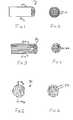
- FIG. 1is a schematic view of carbon fibers having an annual ring layered structure according to the present invention.
- FIG. 2is a cross-sectional view along line 2 — 2 of FIG. 1 .
- FIG. 3is a schematic view of carbon fibers having a radial layered structure according to the present invention.
- FIG. 4is a cross-sectional view along line 4 — 4 of FIG. 3 .
- FIG. 5is a schematic view of mesophase carbon microbeads with a radial-like structure according to the present invention.
- FIG. 6is a cross-sectional view along line 6 — 6 of FIG. 5 .
- FIG. 7is a scanning electron microscope photograph of standard CF x synthesized from petroleum coke having a plate like morphology.
- FIG. 8is a scanning electron microscope photograph of CF x synthesized from a fibrous carbon material according to the present invention.
- FIG. 9is a graph of cell thickness versus depth of discharge for a prior art cell having CF x synthesized from petroleum coke in comparison to a present invention cell having CF x synthesized from carbon fiber.
- the present inventionrelates to minimization and even elimination of swelling in lithium cells containing CF x as part of the cathode electrode and discharged under high rate applications.
- This improvement in cell functionalityresults from CF x materials being synthesized from carbonaceous precursors having special structural characteristics.
- Preferred precursorsare carbon fibers and MCMB. During discharge, and especially during high rate discharge, these CF x materials retain the layered structure of the carbonaceous precursor.
- lithium ionsUpon being discharged in lithium cells, lithium ions intercalate into the layered carbonaceous structure to react with fluorine, which is attached to the carbon backbone either covalently or ionically. This forms lithium fluoride and the reaction is shown below:
- lithium ionsexist in the electrolyte mostly as solvent solvated ions.
- solvent co-intercalationis also thought to occur.
- the co-intercalated solvent moleculesform a solvated reaction intermediate. This intermediate causes destruction of the carbon structure and results in expansion of the discharged CF x active material.
- solvent moleculesco-intercalate into the layered carbonaceous structure within a shorter period of time.
- Such rapid co-intercalationcreates a relatively high concentration of solvent molecules locally which, in turn, causes destruction or expansion of the layered structure at the local region. Therefore, in order to minimize or eliminate cell swelling, destruction or expansion of the layered carbonaceous structure due to solvent co-intercalation needs to be minimized.
- FIGS. 1 and 2show a schematic of carbon fibers 10 having annual ring layers 12 where graphite crystallite edges are exposed only on the cross section.
- FIGS. 3 and 4show a schematic of carbon fibers 20 with radial layers 22 where the entire fiber surface has the graphite crystallite edges 24 exposed.
- FIGS. 5 and 6show a schematic of a MCMB 30 with a radial-like texture where the entire surface of the microbead has exposed graphite crystallite edges 32 .
- CF x material synthesized from carbon fibersexhibit a markedly different morphology than standard CF x material synthesized from petroleum coke.
- the standard materialdisplays a plate like morphology (FIG. 7 )
- the present invention materialdisplays a fiber like morphology (FIG. 8 ).
- the difference between the materialsis also reflected in the five point BET surface area.
- the surface area of CF x synthesized from petroleum cokeis about 155 m 2 /g, whereas the surface area of CF x synthesized from fibrous materials according to the present invention ranges from about 295 m 2 /g to about 346 m 2 /g.
- the prior art CF x materialhas a mean particle size, by volume %, of about 16.47 ⁇ m, whereas the particle size for the fiber material ranges, by volume %, from about 4.37 ⁇ m to about 6.92 ⁇ m.
- a thermogravimetric/differential thermal analysis (TGA/DTA)was simultaneously conducted on both materials under a flowing argon atmosphere at a rate of 20° C. from room temperature to 750° C., and the results are set forth below in Table 1.
- any carbonaceous material with a structure which restricts an increase in the d 002 spacing between graphite layersis considered a good precursor for CF x synthesis according to the present invention. Accordingly, the use of CF x synthesized from these carbon materials is beneficial to minimize or eliminate cell swelling.
- pulsemeans a short burst of electrical current of a significantly greater amplitude than that of a pre-pulse current immediately prior to the pulse.
- a pulse trainconsists of at least two pulses of electrical current delivered in relatively short succession with or without open circuit rest between the pulses.
- a typical current pulseis of about 15.0 mA/cm 2 to about 35.0 mA/cm 2 .
- An electrochemical cell that possesses sufficient energy density and discharge capacity required to meet the vigorous requirements of implantable medical devicescomprises an anode of a metal selected from Groups IA, IIA and IIIB of the Periodic Table of the Elements.
- Such anode active materialsinclude lithium, sodium, potassium, etc., and their alloys and intermetallic compounds including, for example, Li—Si, Li—Al, Li—B and Li—Si—B alloys and intermetallic compounds.
- the preferred anodecomprises lithium.
- An alternate anodecomprises a lithium alloy such as a lithium-aluminum alloy. The greater the amount of aluminum present by weight in the alloy, however, the lower the energy density of the cell.
- the form of the anodemay vary, but preferably the anode is a thin metal sheet or foil of the anode metal, pressed or rolled on a metallic anode current collector, i.e., preferably comprising titanium, titanium alloy or nickel, to form an anode component. Copper, tungsten and tantalum are also suitable materials for the anode current collector.
- the anode componenthas an extended tab or lead of the same material as the anode current collector, i.e., preferably nickel or titanium, integrally formed therewith such as by welding and contacted by a weld to a cell case of conductive metal in a case-negative electrical configuration.
- the anodemay be formed in some other geometry, such as a bobbin shape, cylinder or pellet to allow an alternate low surface cell design.
- the electrochemical cell of the present inventionfurther comprises a cathode of at least a first electrically conductive material that serves as the other electrode of the cell.
- the cathodeis preferably of solid materials and in one embodiment has a sandwich design as described in the previously referenced U.S. Pat. No. 6,551,747 to Gan.
- the sandwich cathode designcomprises a first active material of a fluorinated carbon compound prepared from the carbonaceous materials described above. Fluorinated carbon is represented by the formula (CF x ) n wherein x varies between about 0.1 to 1.9 and preferably between about 0.5 and 1.2, and (C 2 F) n wherein the n refers to the number of monomer units which can vary widely.
- the sandwich cathode designfurther includes a second active material of a relatively low energy density and a relatively high rate capability in comparison to the first fluorinated carbon cathode active material.
- a second active materialis a transition metal oxide having the general formula SM x V 2 O y where SM is a metal selected from Groups IB to VIIB and VIII of the Periodic Table of Elements, wherein x is about 0.30 to 2.0 and y is about 4.5 to 6.0 in the general formula.
- Another preferred composite transition metal oxide cathode materialincludes V 2 O z wherein z ⁇ 5 is combined with Ag 2 O with silver in either the silver(II), silver(I) or silver(0) oxidation state and CuO with copper in either the copper(II), copper(I) or copper(0) oxidation state to provide the mixed metal oxide having the general formula Cu x Ag y V 2 O z , (CSVO).
- the composite cathode active materialmay be described as a metal oxide-metal oxide-metal oxide, a metal-metal oxide-metal oxide, or a metal-metal-metal oxide and the range of material composition found for Cu x Ag y V 2 O z is preferably about 0.01 ⁇ z ⁇ 6.5.
- Typical forms of CSVOare Cu 0.16 Ag 0.67 V 2 O z with z being about 5.5 and Cu 0.5 Ag 0.5 V 2 O z with z being about 5.75.
- the oxygen contentis designated by z since the exact stoichiometric proportion of oxygen in CSVO can vary depending on whether the cathode material is prepared in an oxidizing atmosphere such as air or oxygen, or in an inert atmosphere such as argon, nitrogen and helium.
- an oxidizing atmospheresuch as air or oxygen
- an inert atmospheresuch as argon, nitrogen and helium.
- One exemplary sandwich cathode electrodehas the following configuration:
- Another exemplary sandwich cathode electrode configurationis:
- Still another configuration for an electrochemical cell with a sandwich electrodehas a lithium anode and a cathode configuration of:
- the second active material of the sandwich cathode designis any material which has a relatively lower energy density but a relatively higher rate capability than the first active material.
- V 2 O 5 , MnO 2 , LiCoO 2 , LiNiO 2 , LiMn 2 O 4 , TiS 2 , CuS, FeS, FeS 2 , CuO, copper vanadium oxide (CVO), and mixtures thereofare useful as the second active material.
- the first and second cathode active materials prepared as described aboveare preferably mixed with a binder material such as a powdered fluoro-polymer, more preferably powdered polytetrafluoroethylene or powdered polyvinylidene fluoride present at about 1 to about 5 weight percent of the cathode mixture.
- a binder materialsuch as a powdered fluoro-polymer, more preferably powdered polytetrafluoroethylene or powdered polyvinylidene fluoride present at about 1 to about 5 weight percent of the cathode mixture.
- a conductive diluentis preferably added to the cathode mixture to improve conductivity.
- Suitable materials for this purposeinclude acetylene black, carbon black and/or graphite or a metallic powder such as powdered nickel, aluminum, titanium and stainless steel.
- the preferred cathode active mixturethus includes a powdered fluoro-polymer binder present at about 3 weight percent, a
- a second embodiment of a present invention cellis constructed according to U.S. Pat. No. 5,639,577 to Takeuchi et al.
- This patentdescribes a cathode active blend of fluorinated carbon and a transition metal oxide.
- the fluorinated carbonis prepared from the carbonaceous precursors described above.
- the preferred transition metal oxideis CSVO.
- active materials including SVO as described above with respect to the second cathode active material of the sandwich electrode designare also useful when blended with CF x .
- This cellis described as being particularly useful for high current pulse discharge applications, for example at about 15.0 mA/cm 2 and above.
- Cathode components for incorporation into an electrochemical cell according to the present inventionmay be prepared by rolling, spreading or pressing the first and second cathode active materials onto a suitable current collector selected from the group consisting of stainless steel, titanium, tantalum, platinum, gold, aluminum, cobalt nickel alloys, nickel-containing alloys, highly alloyed ferritic stainless steel containing molybdenum and chromium, and nickel-, chromium- and molybdenum-containing alloys.
- the preferred current collector materialis titanium, and most preferably the titanium cathode current collector has a thin layer of graphite/carbon material, iridium, iridium oxide or platinum applied thereto.
- Cathodes prepared as described abovemay be in the form of one or more plates operatively associated with at least one or more plates of anode material, or in the form of a strip wound with a corresponding strip of anode material in a structure similar to a “jellyroll”.
- the cathodeis separated from the Group IA, IIA or IIIB anode by a suitable separator material.
- the separatoris of electrically insulative material, and the separator material also is chemically unreactive with the anode and cathode active materials and both chemically unreactive with and insoluble in the electrolyte.
- the separator materialhas a degree of porosity sufficient to allow flow there through of the electrolyte during the electrochemical reaction of the cell.
- Illustrative separator materialsinclude fabrics woven from fluoropolymeric fibers including polyvinylidine fluoride, polyethylenetetrafluoroethylene, and polyethylenechlorotrifluoroethylene used either alone or laminated with a fluoropolymeric microporous film, non-woven glass, polypropylene, polyethylene, glass fiber materials, ceramics, polytetrafluoroethylene membrane commercially available under the designation ZITEX (Chemplast Inc.), polypropylene membrane commercially available under the designation CELGARD (Celanese Plastic Company, Inc.) and a membrane commercially available under the designation DEXIGLAS (C.H. Dexter, Div., Dexter Corp.).
- fluoropolymeric fibersincluding polyvinylidine fluoride, polyethylenetetrafluoroethylene, and polyethylenechlorotrifluoroethylene used either alone or laminated with a fluoropolymeric microporous film, non-woven glass, polypropylene, polyethylene, glass fiber materials
- the electrochemical cells of the present inventionfurther include a nonaqueous, ionically conductive electrolyte which serves as a medium for migration of ions between the anode and the cathode electrodes during the electrochemical reactions of the cells.
- the electrochemical reaction at the electrodesinvolves conversion of ions in atomic or molecular forms which migrate from the anode to the cathode.
- nonaqueous electrolytes suitable for the present inventionare substantially inert to the anode and cathode materials, and they exhibit those physical properties necessary for ionic transport, namely, low viscosity, low surface tension and wettability.
- a suitable electrolytehas an inorganic, ionically conductive salt dissolved in a nonaqueous solvent, and more preferably, the electrolyte includes an ionizable alkali metal salt dissolved in a mixture of aprotic organic solvents comprising a low viscosity solvent and a high permittivity solvent.
- the inorganic, ionically conductive saltserves as the vehicle for migration of the anode ions to intercalate or react with the cathode active material.
- the ion forming alkali metal saltis similar to the alkali metal comprising the anode.
- the alkali metal salt of the electrolyteis a lithium based salt.
- Known lithium salts that are useful as a vehicle for transport of alkali metal ions from the anode to the cathodeinclude LiPF 6 , LiBF 4 , LiAsF 6 , LiSbF 6 , LiClO 4 , LiO 2 , LiAlCl 4 , LiGaCl 4 , LiC(SO 2 CF 3 ) 3 , LiN(SO 2 CF 3 ) 2 , LiSCN, LiO 3 SCF 3 , LiC 6 F 5 SO 3 , LiO 2 CCF 3 , LiSO 6 F, LiB(C 6 H 5 ) 4 , LiCF 3 SO 3 , and mixtures thereof.
- Low viscosity solvents useful with the present inventioninclude esters, linear and cyclic ethers and dialkyl carbonates such as tetrahydrofuran (THF), methyl acetate (MA), diglyme, trigylme, tetragylme, dimethyl carbonate (DMC), 1,2-dimethoxyethane (DME), 1,2-diethoxyethane (DEE), 1-ethoxy,2-methoxyethane (EME), ethyl methyl carbonate, methyl propyl carbonate, ethyl propyl carbonate, diethyl carbonate, dipropyl carbonate, and mixtures thereof, and high permittivity solvents include cyclic carbonates, cyclic esters and cyclic amides such as propylene carbonate (PC), ethylene carbonate (EC), butylene carbonate, acetonitrile, dimethyl sulfoxide, dimethyl formamide, dimethyl acetamide, ⁇ -valerolactone,
- a preferred chemistry for a sandwich cathode electrode according to the present inventionhas a lithium metal anode and a cathode electrode comprising (SVO) and fluorinated carbon (CF x ).
- CF x materialis sandwiched between two cathode current collectors. This assembly is, in turn, sandwiched between two layers of SVO material.
- the electrolyte activating the cellsis 0.8M to 1.5M LiAsF 6 or LiPF 6 in a 1:1, by volume, mixture of propylene carbonate and 1,2-dimethoxyethane.
- the electrolytealso contains 0.05M dibenzyl carbonate (DBC), as described in U.S. Pat. Nos. 5,753,389 and 6,221,534, both to Gan et al. and both assigned to the assignee of the present invention and incorporated herein by reference.
- DBCdibenzyl carbonate
- test cellswere constructed having lithium anode material pressed on a nickel current collector screen.
- the cathodesused two layers of titanium current collector screen and had the sandwich configuration of: SVO/current collector/CF x /current collector/SVO.
- a prismatic cell stack assemblycomprising two layers of microporous membrane polypropylene separator disposed between the anode and cathode was prepared.
- the electrode assemblywas then hermetically sealed in a stainless steel casing in a case negative configuration and activated with an electrolyte of 1.0M LiAsF 6 in a 50:50 mixture, by volume of PC and DME with 0.05M DBC dissolved therein.
- the theoretical capacity of the cellswas 2.645 Ah.
- test cellsTwo of the test cells were constructed having CF x synthesized from petroleum coke (group 1) while four of the cells were constructed with CF x synthesized from carbon fiber (group 2).
- a representative cell from each of groups 1 and 2was accelerated pulse discharged. This discharge regime consisted of pulse trains of four 10 second 2 Amp current pulses with a 15 second rest between each pulse. The pulse trains were applied every 30 minutes. The capacities delivered to three voltages cut-offs are summarized in Table 2.
Landscapes
- Chemical & Material Sciences (AREA)
- Electrochemistry (AREA)
- General Chemical & Material Sciences (AREA)
- Chemical Kinetics & Catalysis (AREA)
- Inorganic Chemistry (AREA)
- Composite Materials (AREA)
- Manufacturing & Machinery (AREA)
- Engineering & Computer Science (AREA)
- Secondary Cells (AREA)
- Battery Electrode And Active Subsutance (AREA)
- Cell Electrode Carriers And Collectors (AREA)
- Electrotherapy Devices (AREA)
- Carbon And Carbon Compounds (AREA)
Abstract
Description
| TABLE 1 | ||||
| Parameter | standard CFx | fiber CFx | ||
| BET surface area (m2/g) | 155 | 295-346 | ||
| particle size volume % (μm) | 16.5 | 4.37-6.92 | ||
| particle size surface area % | 3.97 | 1.71-2.12 | ||
| particle size number % | 0.716 | 0.642-0.686 | ||
| DTA exotherm (° C.) | 667 | 652-656 | ||
| min TGA % weight loss to | 79.5 | 75.7 | ||
| 750° C. | ||||
| max TGA % weight loss to | 83.7 | 83.7 | ||
| 750° C. | ||||
| TABLE 2 | |||
| Capacity at Cut Off | Efficiency at Cut Off | ||
| (mAh) | (%) | ||
| 2. V | 1.7 V | 1.5 V | 2.0 V | 1.7 V | 1.5 | |
| 1 | 1816 | 2069 | 2274 | 68.7 | 78.2 | 86.0 |
| 2 | 1967 | 2205 | 2320 | 74.4 | 83.4 | 87.7 |
Claims (31)
Priority Applications (1)
| Application Number | Priority Date | Filing Date | Title |
|---|---|---|---|
| US09/859,558US6783888B2 (en) | 2000-05-18 | 2001-05-17 | Control of cell swelling by the proper choice of carbon monofluoride (CFx) cathode materials in high rate defibrillator cells |
Applications Claiming Priority (2)
| Application Number | Priority Date | Filing Date | Title |
|---|---|---|---|
| US20536100P | 2000-05-18 | 2000-05-18 | |
| US09/859,558US6783888B2 (en) | 2000-05-18 | 2001-05-17 | Control of cell swelling by the proper choice of carbon monofluoride (CFx) cathode materials in high rate defibrillator cells |
Publications (2)
| Publication Number | Publication Date |
|---|---|
| US20020012844A1 US20020012844A1 (en) | 2002-01-31 |
| US6783888B2true US6783888B2 (en) | 2004-08-31 |
Family
ID=22761887
Family Applications (1)
| Application Number | Title | Priority Date | Filing Date |
|---|---|---|---|
| US09/859,558Expired - LifetimeUS6783888B2 (en) | 2000-05-18 | 2001-05-17 | Control of cell swelling by the proper choice of carbon monofluoride (CFx) cathode materials in high rate defibrillator cells |
Country Status (4)
| Country | Link |
|---|---|
| US (1) | US6783888B2 (en) |
| EP (1) | EP1156541B1 (en) |
| JP (1) | JP2002100361A (en) |
| CA (1) | CA2348175C (en) |
Cited By (20)
| Publication number | Priority date | Publication date | Assignee | Title |
|---|---|---|---|---|
| US20030124427A1 (en)* | 2001-11-02 | 2003-07-03 | Takeuchi Esther S. | Noble metals coated on titanium current collectors for use in nonaqueous Li / CFx cells |
| US20070077488A1 (en)* | 2005-10-04 | 2007-04-05 | Kaimin Chen | Power capability of a cathode |
| US20070178381A1 (en)* | 2006-01-17 | 2007-08-02 | Howard William G | Implantable medical device battery |
| US20070178378A1 (en)* | 2006-01-31 | 2007-08-02 | Merritt Donald R | Resistance-stabilizing additives for electrolyte |
| US20070275284A1 (en)* | 2003-02-13 | 2007-11-29 | Merritt Donald R | Liquid electrolyte for an electrochemical cell |
| US20070281213A1 (en)* | 2006-06-02 | 2007-12-06 | Gentcorp Ltd. | Carbon Monofluoride Cathode Materials Providing Simplified Elective Replacement Indication |
| US20080038643A1 (en)* | 2006-02-01 | 2008-02-14 | Greatbatch Ltd. | Lithium/Fluorinated Carbon Cell For High-Rate Pulsatlie Applications |
| US20090181302A1 (en)* | 2006-01-31 | 2009-07-16 | Medtronic, Inc. | Electrolyte additive for performance stability of batteries |
| US7718319B2 (en) | 2006-09-25 | 2010-05-18 | Board Of Regents, The University Of Texas System | Cation-substituted spinel oxide and oxyfluoride cathodes for lithium ion batteries |
| US20110045253A1 (en)* | 2007-09-10 | 2011-02-24 | Medtronic, Inc. | Control of properties of printed electrodes in at least two dimensions |
| US20110104542A1 (en)* | 2009-10-30 | 2011-05-05 | Greatbatch Ltd. | Screen-less anode design concepts for low cost lithium electrochemical cells for use in implantable medical device applications |
| WO2011091178A1 (en) | 2010-01-24 | 2011-07-28 | Medtronic, Inc. | Non-rechargeable battery for an implantable medical devices |
| US20110183215A1 (en)* | 2006-04-10 | 2011-07-28 | Greatbatch Ltd. | Layered Electrode For An Electrochemical Cell |
| US9065144B2 (en) | 2010-08-12 | 2015-06-23 | Cardiac Pacemakers, Inc. | Electrode including a 3D framework formed of fluorinated carbon |
| US9083048B2 (en) | 2010-08-12 | 2015-07-14 | Cardiac Pacemakers, Inc. | Carbon monofluoride impregnated current collector including a 3D framework |
| WO2017087807A1 (en) | 2015-11-19 | 2017-05-26 | The Regents Of The University Of Michigan | State of battery health estimation based on swelling characteristics |
| WO2018118770A1 (en)* | 2016-12-21 | 2018-06-28 | Medtronic, Inc. | Implantable medical device batteries with milled fluorinated carbon fibers, devices, and methods |
| US10847780B2 (en) | 2016-09-16 | 2020-11-24 | Pacesetter, Inc. | Battery electrode and methods of making |
| US11217846B2 (en) | 2017-03-16 | 2022-01-04 | Eaglepicher Technologies, Llc | Electrochemical cell |
| US11362316B2 (en) | 2018-12-28 | 2022-06-14 | Pacesetter, Inc. | Battery having hybrid cathode configuration |
Families Citing this family (17)
| Publication number | Priority date | Publication date | Assignee | Title |
|---|---|---|---|---|
| US6692871B2 (en)* | 2000-11-17 | 2004-02-17 | Wilson Greatbatch Ltd. | Double current collector cathode design for alkali metal electrochemical cells having short circuit safety characteristics |
| GB2419132B (en)* | 2004-10-04 | 2011-01-19 | C Tech Innovation Ltd | Method of production of fluorinated carbon nanostructures |
| DE102006021158A1 (en) | 2006-05-06 | 2007-11-08 | Biotronik Crm Patent Ag | Electrode for a lithium battery and method of making the same |
| US20080085449A1 (en)* | 2006-10-09 | 2008-04-10 | Gentcorp Ltd. | Ultra-Miniature Electrochemical Cell And Fabrication Method |
| JP5091573B2 (en)* | 2007-07-17 | 2012-12-05 | 富士重工業株式会社 | Electricity storage device |
| EP2747177B1 (en)* | 2012-12-21 | 2017-07-12 | Karlsruher Institut für Technologie | Lithium/graphite fluoride primary battery and method for its manufacturing |
| JP6408463B2 (en)* | 2013-05-09 | 2018-10-17 | 住友化学株式会社 | Positive electrode material and manufacturing method thereof |
| US20150044569A1 (en)* | 2013-08-07 | 2015-02-12 | Rutgers, The State University Of New Jersey | High energy cathode materials for primary batteries |
| US9755235B2 (en) | 2014-07-17 | 2017-09-05 | Ada Technologies, Inc. | Extreme long life, high energy density batteries and method of making and using the same |
| US10879503B2 (en) | 2014-07-21 | 2020-12-29 | Johnson & Johnson Vision Care, Inc. | Methods for the manufacture of flexible microbatteries |
| SG11201700212RA (en)* | 2014-07-21 | 2017-02-27 | Flexel Llc | Flexible micro-battery |
| WO2016209460A2 (en) | 2015-05-21 | 2016-12-29 | Ada Technologies, Inc. | High energy density hybrid pseudocapacitors and method of making and using the same |
| US10692659B2 (en) | 2015-07-31 | 2020-06-23 | Ada Technologies, Inc. | High energy and power electrochemical device and method of making and using same |
| US11024846B2 (en) | 2017-03-23 | 2021-06-01 | Ada Technologies, Inc. | High energy/power density, long cycle life, safe lithium-ion battery capable of long-term deep discharge/storage near zero volt and method of making and using the same |
| CN110783586B (en)* | 2019-11-21 | 2021-10-08 | 华南师范大学 | A kind of high power density primary battery electrolyte and preparation method and application thereof |
| CN111244413B (en)* | 2020-01-16 | 2021-06-29 | 河南工业大学 | A kind of LTO/CVO composite material and preparation method thereof |
| CN115347264B (en)* | 2022-08-24 | 2025-01-28 | 重庆大学 | A device for intelligent pulse discharge vaporization of retired lithium-ion battery positive electrode current collector |
Citations (20)
| Publication number | Priority date | Publication date | Assignee | Title |
|---|---|---|---|---|
| US4271242A (en) | 1977-06-24 | 1981-06-02 | Matsushita Electric Industrial Co., Ltd. | Active material for positive electrode of battery |
| JPS58191221A (en) | 1982-05-01 | 1983-11-08 | Showa Denko Kk | Fluorocarbon type fiber |
| JPS58223264A (en) | 1982-06-18 | 1983-12-24 | Nobuatsu Watanabe | Active mass for battery |
| US4578327A (en) | 1983-04-05 | 1986-03-25 | Asahikasei Kabushiki Kaisha | Electric cells using fluorinated graphite as active material of positive electrode |
| US4681823A (en) | 1986-05-19 | 1987-07-21 | Allied Corporation | Lithium/fluorinated carbon battery with no voltage delay |
| US4684591A (en) | 1983-06-09 | 1987-08-04 | Daikin Kogyo Co., Ltd. | Active materials for batteries |
| US4737423A (en) | 1985-12-30 | 1988-04-12 | Allied Corporation | Cathode active material for metal of CFX battery |
| US4855121A (en) | 1987-01-05 | 1989-08-08 | Societe Atochem | Continuous process for the preparation of carbon polymonofluoride and apparatus therefor |
| US4908198A (en) | 1986-06-02 | 1990-03-13 | The Electrosynthesis Company, Inc. | Fluorinated carbons and methods of manufacture |
| US5017444A (en) | 1989-08-31 | 1991-05-21 | Mitsubishi Kasei Corporation | Lithium cell |
| US5175066A (en) | 1988-12-26 | 1992-12-29 | Centre National De La Recherche Scientifique (Cnrs) | Rechargeable battery with solid electrolyte |
| US5180642A (en)* | 1992-02-24 | 1993-01-19 | Medtronic, Inc. | Electrochemical cells with end-of-service indicator |
| US5639577A (en) | 1996-04-16 | 1997-06-17 | Wilson Greatbatch Ltd. | Nonaqueous electrochemical cell having a mixed cathode and method of preparation |
| US5667916A (en)* | 1996-05-10 | 1997-09-16 | Wilson Greatbatch Ltd. | Mixed cathode formulation for achieving end-of-life indication |
| US5712062A (en) | 1992-11-06 | 1998-01-27 | Daikin Industries, Ltd. | Carbon fluoride particles, preparation process and uses of the same |
| US5744258A (en) | 1996-12-23 | 1998-04-28 | Motorola,Inc. | High power, high energy, hybrid electrode and electrical energy storage device made therefrom |
| US5811206A (en)* | 1997-10-31 | 1998-09-22 | Medtronic, Inc. | Feedthrough pin insulator, assembly and method for electrochemical cell |
| EP0913875A2 (en) | 1997-11-03 | 1999-05-06 | Wilson Greatbatch Ltd. | Perforated film for Modifying the electrochemical surface area of a cell |
| US5902696A (en) | 1997-06-02 | 1999-05-11 | Wilson Greatbatch Ltd. | Separator for nonaqueous electrochemical cells |
| US6551747B1 (en)* | 2000-04-27 | 2003-04-22 | Wilson Greatbatch Ltd. | Sandwich cathode design for alkali metal electrochemical cell with high discharge rate capability |
- 2001
- 2001-05-17JPJP2001188868Apatent/JP2002100361A/ennot_activeWithdrawn
- 2001-05-17USUS09/859,558patent/US6783888B2/ennot_activeExpired - Lifetime
- 2001-05-18EPEP01112257Apatent/EP1156541B1/ennot_activeExpired - Lifetime
- 2001-05-18CACA002348175Apatent/CA2348175C/ennot_activeExpired - Fee Related
Patent Citations (21)
| Publication number | Priority date | Publication date | Assignee | Title |
|---|---|---|---|---|
| US4271242A (en) | 1977-06-24 | 1981-06-02 | Matsushita Electric Industrial Co., Ltd. | Active material for positive electrode of battery |
| JPS58191221A (en) | 1982-05-01 | 1983-11-08 | Showa Denko Kk | Fluorocarbon type fiber |
| JPS58223264A (en) | 1982-06-18 | 1983-12-24 | Nobuatsu Watanabe | Active mass for battery |
| US4578327A (en) | 1983-04-05 | 1986-03-25 | Asahikasei Kabushiki Kaisha | Electric cells using fluorinated graphite as active material of positive electrode |
| US4684591A (en) | 1983-06-09 | 1987-08-04 | Daikin Kogyo Co., Ltd. | Active materials for batteries |
| US4737423A (en) | 1985-12-30 | 1988-04-12 | Allied Corporation | Cathode active material for metal of CFX battery |
| US4681823A (en) | 1986-05-19 | 1987-07-21 | Allied Corporation | Lithium/fluorinated carbon battery with no voltage delay |
| US5116592A (en) | 1986-06-02 | 1992-05-26 | The Electrosynthesis Company, Inc. | Fluorinated carbons and uses thereof |
| US4908198A (en) | 1986-06-02 | 1990-03-13 | The Electrosynthesis Company, Inc. | Fluorinated carbons and methods of manufacture |
| US4855121A (en) | 1987-01-05 | 1989-08-08 | Societe Atochem | Continuous process for the preparation of carbon polymonofluoride and apparatus therefor |
| US5175066A (en) | 1988-12-26 | 1992-12-29 | Centre National De La Recherche Scientifique (Cnrs) | Rechargeable battery with solid electrolyte |
| US5017444A (en) | 1989-08-31 | 1991-05-21 | Mitsubishi Kasei Corporation | Lithium cell |
| US5180642A (en)* | 1992-02-24 | 1993-01-19 | Medtronic, Inc. | Electrochemical cells with end-of-service indicator |
| US5712062A (en) | 1992-11-06 | 1998-01-27 | Daikin Industries, Ltd. | Carbon fluoride particles, preparation process and uses of the same |
| US5639577A (en) | 1996-04-16 | 1997-06-17 | Wilson Greatbatch Ltd. | Nonaqueous electrochemical cell having a mixed cathode and method of preparation |
| US5667916A (en)* | 1996-05-10 | 1997-09-16 | Wilson Greatbatch Ltd. | Mixed cathode formulation for achieving end-of-life indication |
| US5744258A (en) | 1996-12-23 | 1998-04-28 | Motorola,Inc. | High power, high energy, hybrid electrode and electrical energy storage device made therefrom |
| US5902696A (en) | 1997-06-02 | 1999-05-11 | Wilson Greatbatch Ltd. | Separator for nonaqueous electrochemical cells |
| US5811206A (en)* | 1997-10-31 | 1998-09-22 | Medtronic, Inc. | Feedthrough pin insulator, assembly and method for electrochemical cell |
| EP0913875A2 (en) | 1997-11-03 | 1999-05-06 | Wilson Greatbatch Ltd. | Perforated film for Modifying the electrochemical surface area of a cell |
| US6551747B1 (en)* | 2000-04-27 | 2003-04-22 | Wilson Greatbatch Ltd. | Sandwich cathode design for alkali metal electrochemical cell with high discharge rate capability |
Non-Patent Citations (2)
| Title |
|---|
| 01112257.9, Abstract, Undated. |
| EP 01112257.9, Abstract, Undated. |
Cited By (40)
| Publication number | Priority date | Publication date | Assignee | Title |
|---|---|---|---|---|
| US20030124427A1 (en)* | 2001-11-02 | 2003-07-03 | Takeuchi Esther S. | Noble metals coated on titanium current collectors for use in nonaqueous Li / CFx cells |
| US7005214B2 (en)* | 2001-11-02 | 2006-02-28 | Wilson Greatbatch Technologies, Inc. | Noble metals coated on titanium current collectors for use in nonaqueous Li/CFx cells |
| US20060141340A1 (en)* | 2001-11-02 | 2006-06-29 | Wilson Greatbatch Technologies, Inc. | Method For Coating Noble Metals On Titanium Current Collectors For Use In Nonaqueous Li/CFx Cells |
| US8268466B2 (en)* | 2001-11-02 | 2012-09-18 | Greatbatch Ltd. | Method for coating noble metals on titanium current collectors for use in nonaqueous Li/CFx cells |
| US20070275284A1 (en)* | 2003-02-13 | 2007-11-29 | Merritt Donald R | Liquid electrolyte for an electrochemical cell |
| US20070077488A1 (en)* | 2005-10-04 | 2007-04-05 | Kaimin Chen | Power capability of a cathode |
| US20070178381A1 (en)* | 2006-01-17 | 2007-08-02 | Howard William G | Implantable medical device battery |
| US7824805B2 (en) | 2006-01-17 | 2010-11-02 | Medtronic, Inc. | Implantable medical device battery |
| US7807300B2 (en) | 2006-01-31 | 2010-10-05 | Medtronic, Inc. | Resistance-stabilizing additives for electrolyte |
| US20090181302A1 (en)* | 2006-01-31 | 2009-07-16 | Medtronic, Inc. | Electrolyte additive for performance stability of batteries |
| US20100136426A1 (en)* | 2006-01-31 | 2010-06-03 | Medtronic, Inc. | Resistance-stabilizing additives for electrolyte |
| US20070178378A1 (en)* | 2006-01-31 | 2007-08-02 | Merritt Donald R | Resistance-stabilizing additives for electrolyte |
| US20080038643A1 (en)* | 2006-02-01 | 2008-02-14 | Greatbatch Ltd. | Lithium/Fluorinated Carbon Cell For High-Rate Pulsatlie Applications |
| US8685568B2 (en) | 2006-02-01 | 2014-04-01 | Greatbatch Ltd. | Lithium/fluorinated carbon cell for high-rate pulsatlie applications |
| US20110183215A1 (en)* | 2006-04-10 | 2011-07-28 | Greatbatch Ltd. | Layered Electrode For An Electrochemical Cell |
| US20070281213A1 (en)* | 2006-06-02 | 2007-12-06 | Gentcorp Ltd. | Carbon Monofluoride Cathode Materials Providing Simplified Elective Replacement Indication |
| US7718319B2 (en) | 2006-09-25 | 2010-05-18 | Board Of Regents, The University Of Texas System | Cation-substituted spinel oxide and oxyfluoride cathodes for lithium ion batteries |
| US8722246B2 (en) | 2006-09-25 | 2014-05-13 | Board Of Regents Of The University Of Texas System | Cation-substituted spinel oxide and oxyfluoride cathodes for lithium ion batteries |
| US20110045253A1 (en)* | 2007-09-10 | 2011-02-24 | Medtronic, Inc. | Control of properties of printed electrodes in at least two dimensions |
| US8871379B2 (en) | 2009-10-30 | 2014-10-28 | Greatbatch Ltd. | Screen-less anode design concepts for low cost lithium electrochemical cells for use in implantable medical device applications |
| US20110104542A1 (en)* | 2009-10-30 | 2011-05-05 | Greatbatch Ltd. | Screen-less anode design concepts for low cost lithium electrochemical cells for use in implantable medical device applications |
| WO2011091178A1 (en) | 2010-01-24 | 2011-07-28 | Medtronic, Inc. | Non-rechargeable battery for an implantable medical devices |
| WO2011091176A1 (en) | 2010-01-24 | 2011-07-28 | Medtronic, Inc. | Method of making a battery including applying a cathode material slurry to a current collector |
| WO2011091179A1 (en) | 2010-01-24 | 2011-07-28 | Medtronic, Inc. | Method of making a battery including applying a cathode material slurry to a current collector |
| US20110179637A1 (en)* | 2010-01-24 | 2011-07-28 | Kevin Wilmot Eberman | Slurry coating method for making batteries |
| US20110184482A1 (en)* | 2010-01-24 | 2011-07-28 | Kevin Wilmot Eberman | Non-rechargeable batteries and implantable medical devices |
| US9559353B2 (en) | 2010-01-24 | 2017-01-31 | Medtronic, Inc. | Implantable medical devices with low volume batteries, and systems |
| US20110184483A1 (en)* | 2010-01-24 | 2011-07-28 | Norton John D | Implantable medical devices with low volume batteries, and systems |
| US9077030B2 (en) | 2010-01-24 | 2015-07-07 | Medtronic, Inc. | Implantable medical devices with low volume batteries, and systems |
| US10124179B2 (en) | 2010-01-24 | 2018-11-13 | Medtronic, Inc. | Implantable medical devices with low volume batteries, and systems |
| US9065144B2 (en) | 2010-08-12 | 2015-06-23 | Cardiac Pacemakers, Inc. | Electrode including a 3D framework formed of fluorinated carbon |
| US10069147B2 (en) | 2010-08-12 | 2018-09-04 | Cardiac Pacemakers, Inc. | Method of making a carbon monofluoride impregnated current collector including a 3D framework |
| US9083048B2 (en) | 2010-08-12 | 2015-07-14 | Cardiac Pacemakers, Inc. | Carbon monofluoride impregnated current collector including a 3D framework |
| WO2017087807A1 (en) | 2015-11-19 | 2017-05-26 | The Regents Of The University Of Michigan | State of battery health estimation based on swelling characteristics |
| US11623526B2 (en) | 2015-11-19 | 2023-04-11 | The Regents Of The University Of Michigan | State of battery health estimation based on swelling characteristics |
| US10847780B2 (en) | 2016-09-16 | 2020-11-24 | Pacesetter, Inc. | Battery electrode and methods of making |
| WO2018118770A1 (en)* | 2016-12-21 | 2018-06-28 | Medtronic, Inc. | Implantable medical device batteries with milled fluorinated carbon fibers, devices, and methods |
| US10661090B2 (en) | 2016-12-21 | 2020-05-26 | Medtronic, Inc. | Implantable medical device batteries with milled fluorinated carbon fibers, devices, and methods |
| US11217846B2 (en) | 2017-03-16 | 2022-01-04 | Eaglepicher Technologies, Llc | Electrochemical cell |
| US11362316B2 (en) | 2018-12-28 | 2022-06-14 | Pacesetter, Inc. | Battery having hybrid cathode configuration |
Also Published As
| Publication number | Publication date |
|---|---|
| EP1156541B1 (en) | 2013-01-30 |
| JP2002100361A (en) | 2002-04-05 |
| EP1156541A2 (en) | 2001-11-21 |
| EP1156541A3 (en) | 2003-03-26 |
| CA2348175C (en) | 2006-01-31 |
| CA2348175A1 (en) | 2001-11-18 |
| US20020012844A1 (en) | 2002-01-31 |
Similar Documents
| Publication | Publication Date | Title |
|---|---|---|
| US6783888B2 (en) | Control of cell swelling by the proper choice of carbon monofluoride (CFx) cathode materials in high rate defibrillator cells | |
| US6645670B2 (en) | Efficient cell stack for cells with double current collectors sandwich cathodes | |
| US6171729B1 (en) | Control of swelling in alkali metal electrochemical cells | |
| EP1150366B1 (en) | Sandwich cathode design for alkali metal electrochemical cell with high discharge rate capability | |
| US6228534B1 (en) | Annealing of mixed metal oxide electrodes to reduce polarization resistance | |
| US6692871B2 (en) | Double current collector cathode design for alkali metal electrochemical cells having short circuit safety characteristics | |
| US6737191B2 (en) | Double current collector negative electrode design for alkali metal ion electrochemical cells | |
| US7018743B2 (en) | Dual chemistry electrode design | |
| US6451483B1 (en) | Enhanced capacity Li/CFx electrochemical cell | |
| US6673493B2 (en) | Double current collector cathode design using the same active material in varying formulations for alkali metal or ion electrochemical cells | |
| EP0829911A2 (en) | Ternary solvent nonaqueous organic electrolyte for alkali metal electrochemical cells | |
| US6926991B2 (en) | SVO/CFx parallel cell design within the same casing | |
| US6936379B2 (en) | Method for electrode design for implantable device applications that require the elective replacement indicator (ERI) | |
| US20030134188A1 (en) | Sandwich electrode design having relatively thin current collectors | |
| US7108942B1 (en) | Efficient electrode assembly design for cells with alkali metal anodes | |
| US8192867B2 (en) | Hybrid cathode design for an electrochemical cell | |
| EP1324418A1 (en) | High energy density rechargeable cell for medical device applications | |
| EP1914823B1 (en) | Hybrid cathode design for an electrochemical cell | |
| US20100196765A1 (en) | Reducing DC Resistance In Electrochemical Cells By Increasing Cathode Basis Weight | |
| US9231256B2 (en) | Flat and high-density cathodes for use in electrochemical cells | |
| US20110183215A1 (en) | Layered Electrode For An Electrochemical Cell |
Legal Events
| Date | Code | Title | Description |
|---|---|---|---|
| AS | Assignment | Owner name:WILSON GREATBATCH LTD., NEW YORK Free format text:ASSIGNMENT OF ASSIGNORS INTEREST;ASSIGNORS:GAN, HONG;SMESKO, SALLY ANN;TAKEUCHI, ESTHER S.;AND OTHERS;REEL/FRAME:011852/0731;SIGNING DATES FROM 20010515 TO 20010524 | |
| STCF | Information on status: patent grant | Free format text:PATENTED CASE | |
| CC | Certificate of correction | ||
| AS | Assignment | Owner name:GREATBATCH, LTD. (NEW YORK CORPORATION), NEW YORK Free format text:CHANGE OF NAME;ASSIGNOR:WILSON GREATBATCH,TD.;REEL/FRAME:019520/0743 Effective date:20050524 | |
| AS | Assignment | Owner name:MANUFACTURERS AND TRADERS TRUST COMPANY,NEW YORK Free format text:SECURITY INTEREST;ASSIGNOR:GREATBATCH LTD.;REEL/FRAME:020571/0205 Effective date:20070522 Owner name:MANUFACTURERS AND TRADERS TRUST COMPANY, NEW YORK Free format text:SECURITY INTEREST;ASSIGNOR:GREATBATCH LTD.;REEL/FRAME:020571/0205 Effective date:20070522 | |
| FEPP | Fee payment procedure | Free format text:PAYOR NUMBER ASSIGNED (ORIGINAL EVENT CODE: ASPN); ENTITY STATUS OF PATENT OWNER: LARGE ENTITY | |
| FPAY | Fee payment | Year of fee payment:4 | |
| REMI | Maintenance fee reminder mailed | ||
| FPAY | Fee payment | Year of fee payment:8 | |
| AS | Assignment | Owner name:MANUFACTURERS AND TRADERS TRUST COMPANY, NEW YORK Free format text:SECURITY INTEREST;ASSIGNORS:GREATBATCH, INC.;GREATBATCH LTD.;ELECTROCHEM SOLUTIONS, INC.;AND OTHERS;REEL/FRAME:036980/0482 Effective date:20151027 | |
| FPAY | Fee payment | Year of fee payment:12 | |
| AS | Assignment | Owner name:WELLS FARGO BANK, NATIONAL ASSOCIATION, AS ADMINISTRATIVE AGENT, VIRGINIA Free format text:SECURITY INTEREST;ASSIGNORS:GREATBATCH LTD.;ELECTROCHEM SOLUTIONS, INC.;LAKE REGION MEDICAL, INC.;AND OTHERS;REEL/FRAME:057468/0056 Effective date:20210902 | |
| AS | Assignment | Owner name:MICRO POWER ELECTRONICS, INC., NEW YORK Free format text:RELEASE BY SECURED PARTY;ASSIGNOR:MANUFACTURERS AND TRADERS TRUST COMPANY (AS ADMINISTRATIVE AGENT);REEL/FRAME:060938/0069 Effective date:20210903 Owner name:PRECIMED INC., NEW YORK Free format text:RELEASE BY SECURED PARTY;ASSIGNOR:MANUFACTURERS AND TRADERS TRUST COMPANY (AS ADMINISTRATIVE AGENT);REEL/FRAME:060938/0069 Effective date:20210903 Owner name:GREATBATCH-GLOBE TOOL, INC., NEW YORK Free format text:RELEASE BY SECURED PARTY;ASSIGNOR:MANUFACTURERS AND TRADERS TRUST COMPANY (AS ADMINISTRATIVE AGENT);REEL/FRAME:060938/0069 Effective date:20210903 Owner name:NEURONEXUS TECHNOLOGIES, INC., NEW YORK Free format text:RELEASE BY SECURED PARTY;ASSIGNOR:MANUFACTURERS AND TRADERS TRUST COMPANY (AS ADMINISTRATIVE AGENT);REEL/FRAME:060938/0069 Effective date:20210903 Owner name:ELECTROCHEM SOLUTIONS, INC., NEW YORK Free format text:RELEASE BY SECURED PARTY;ASSIGNOR:MANUFACTURERS AND TRADERS TRUST COMPANY (AS ADMINISTRATIVE AGENT);REEL/FRAME:060938/0069 Effective date:20210903 Owner name:GREATBATCH LTD., NEW YORK Free format text:RELEASE BY SECURED PARTY;ASSIGNOR:MANUFACTURERS AND TRADERS TRUST COMPANY (AS ADMINISTRATIVE AGENT);REEL/FRAME:060938/0069 Effective date:20210903 Owner name:GREATBATCH, INC., NEW YORK Free format text:RELEASE BY SECURED PARTY;ASSIGNOR:MANUFACTURERS AND TRADERS TRUST COMPANY (AS ADMINISTRATIVE AGENT);REEL/FRAME:060938/0069 Effective date:20210903 Owner name:GREATBATCH LTD., NEW YORK Free format text:RELEASE BY SECURED PARTY;ASSIGNOR:MANUFACTURERS AND TRADERS TRUST COMPANY (AS ADMINISTRATIVE AGENT);REEL/FRAME:058574/0437 Effective date:20210903 | |
| AS | Assignment | Owner name:MICRO POWER ELECTRONICS, INC., NEW YORK Free format text:RELEASE BY SECURED PARTY;ASSIGNOR:MANUFACTURERS AND TRADERS TRUST COMPANY (AS ADMINISTRATIVE AGENT);REEL/FRAME:061659/0858 Effective date:20210903 Owner name:PRECIMED INC., NEW YORK Free format text:RELEASE BY SECURED PARTY;ASSIGNOR:MANUFACTURERS AND TRADERS TRUST COMPANY (AS ADMINISTRATIVE AGENT);REEL/FRAME:061659/0858 Effective date:20210903 Owner name:GREATBATCH-GLOBE TOOL, INC., NEW YORK Free format text:RELEASE BY SECURED PARTY;ASSIGNOR:MANUFACTURERS AND TRADERS TRUST COMPANY (AS ADMINISTRATIVE AGENT);REEL/FRAME:061659/0858 Effective date:20210903 Owner name:NEURONEXUS TECHNOLOGIES, INC., NEW YORK Free format text:RELEASE BY SECURED PARTY;ASSIGNOR:MANUFACTURERS AND TRADERS TRUST COMPANY (AS ADMINISTRATIVE AGENT);REEL/FRAME:061659/0858 Effective date:20210903 Owner name:ELECTROCHEM SOLUTIONS, INC., NEW YORK Free format text:RELEASE BY SECURED PARTY;ASSIGNOR:MANUFACTURERS AND TRADERS TRUST COMPANY (AS ADMINISTRATIVE AGENT);REEL/FRAME:061659/0858 Effective date:20210903 Owner name:GREATBATCH LTD., NEW YORK Free format text:RELEASE BY SECURED PARTY;ASSIGNOR:MANUFACTURERS AND TRADERS TRUST COMPANY (AS ADMINISTRATIVE AGENT);REEL/FRAME:061659/0858 Effective date:20210903 Owner name:GREATBATCH, INC., NEW YORK Free format text:RELEASE BY SECURED PARTY;ASSIGNOR:MANUFACTURERS AND TRADERS TRUST COMPANY (AS ADMINISTRATIVE AGENT);REEL/FRAME:061659/0858 Effective date:20210903 |