US6783281B2 - Optical fiber converter retaining different sized ferrules - Google Patents
Optical fiber converter retaining different sized ferrulesDownload PDFInfo
- Publication number
- US6783281B2 US6783281B2US10/305,623US30562302AUS6783281B2US 6783281 B2US6783281 B2US 6783281B2US 30562302 AUS30562302 AUS 30562302AUS 6783281 B2US6783281 B2US 6783281B2
- Authority
- US
- United States
- Prior art keywords
- optical fiber
- ferrule
- housing
- cavity
- converter
- Prior art date
- Legal status (The legal status is an assumption and is not a legal conclusion. Google has not performed a legal analysis and makes no representation as to the accuracy of the status listed.)
- Expired - Lifetime
Links
- 239000013307optical fiberSubstances0.000titleclaimsabstractdescription112
- 230000003287optical effectEffects0.000claimsabstractdescription9
- 230000000717retained effectEffects0.000claimsabstractdescription8
- 239000000835fiberSubstances0.000claimsdescription4
- 239000000919ceramicSubstances0.000description1
Images


Classifications
- G—PHYSICS
- G02—OPTICS
- G02B—OPTICAL ELEMENTS, SYSTEMS OR APPARATUS
- G02B6/00—Light guides; Structural details of arrangements comprising light guides and other optical elements, e.g. couplings
- G02B6/24—Coupling light guides
- G02B6/36—Mechanical coupling means
- G02B6/38—Mechanical coupling means having fibre to fibre mating means
- G02B6/3807—Dismountable connectors, i.e. comprising plugs
- G02B6/381—Dismountable connectors, i.e. comprising plugs of the ferrule type, e.g. fibre ends embedded in ferrules, connecting a pair of fibres
- G02B6/3825—Dismountable connectors, i.e. comprising plugs of the ferrule type, e.g. fibre ends embedded in ferrules, connecting a pair of fibres with an intermediate part, e.g. adapter, receptacle, linking two plugs
- G—PHYSICS
- G02—OPTICS
- G02B—OPTICAL ELEMENTS, SYSTEMS OR APPARATUS
- G02B6/00—Light guides; Structural details of arrangements comprising light guides and other optical elements, e.g. couplings
- G02B6/24—Coupling light guides
- G02B6/36—Mechanical coupling means
- G02B6/38—Mechanical coupling means having fibre to fibre mating means
- G02B6/3807—Dismountable connectors, i.e. comprising plugs
- G02B6/389—Dismountable connectors, i.e. comprising plugs characterised by the method of fastening connecting plugs and sockets, e.g. screw- or nut-lock, snap-in, bayonet type
- G02B6/3893—Push-pull type, e.g. snap-in, push-on
Definitions
- the present inventionrelates to an optical fiber converter, and particularly to an optical fiber converter for converting a traditional optical fiber connector into an SFF (Small Form Factor) optical fiber connector.
- SFFSmall Form Factor
- Optical fiber connectorsare widely used in optical communication systems. For example, optical fiber connectors are used to join optical fibers together to form a longer length fiber run, or to connect an optical fiber to a device.
- a conventional connector and an SFF (Small Form Factor) connectorhave ferrules of different diameters.
- a ferruleaccommodates an optical fiber therein.
- a conventional optical fiber connectorsuch as an SC (Subscriber Connector) or FC (Face Connector) type connector, has a ferrule with an outer diameter of approximately 2.5 mm.
- An SFF optical fiber connectorsuch as an LC type connector made to meet a demand for high-density communication ports, has a ferrule with an outer diameter of approximately 1.25 mm.
- the LC type connectoris a connector defined by the Lucent Company, which has become an industrial standard in the field of connectors.
- an object of the present inventionis to provide an optical fiber converter which interconnects two different types of optical fiber connectors.
- Another object of the present inventionis to provide an optical fiber converter which interconnects a conventional optical fiber connector and an SFF optical fiber connector.
- an optical fiber converteris adapted to interconnect a first optical fiber connector and a second optical fiber connector, each connector being of a different type.
- the optical fiber convertercomprises a ferrule subassembly, a sleeve, a spring, a plug housing and a receptacle housing.
- the ferrule subassemblyfurther comprises a first ferrule having a first central hole extending therethrough, a second ferrule having a second central hole extending therethrough, a ferrule holder and an optical fiber.
- the first and second ferrulesare fixedly held by the ferrule holder, the first and second central holes are coaxially aligned, and the optical fiber is retained in the first and second central holes.
- the sleevecoaxially retains the second ferrule and is adapted to receive a ferrule of the second optical fiber connector.
- the plug housingretains the ferrule holder and is adapted to engage with the first optical fiber connector.
- the receptacle housingengages with the plug housing, and is adapted to engage with the second optical fiber connector.
- FIG. 1is a perspective view of an optical fiber converter in accordance with the present invention
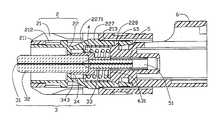
- FIG. 2is a cross-sectional view of the optical fiber converter of FIG. 1;
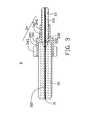
- FIG. 3is a cross-sectional view of a ferrule subassembly of the optical fiber converter of FIG. 1;
- FIG. 4is a side view of an inner housing of the optical fiber converter of FIG. 1;
- FIG. 5is a cross-sectional view of the inner housing of FIG. 4;
- FIG. 6is a side view of a receptacle housing of the optical fiber converter of FIG. 1;
- FIG. 7is a cross-sectional view of the receptacle housing of FIG. 6.
- FIG. 8is a side, exploded view of the optical fiber converter of FIG. 1 .
- an optical fiber converter 100 in accordance with the present inventionis adapted to interconnect an SC-type optical fiber connector (not shown) and an LC-type optical fiber connector (not shown).
- the optical fiber converter 100comprises a ferrule subassembly 3 , a sleeve 5 , a spring 4 , a plug housing 2 and an L-shaped receptacle housing 6 .
- the ferrule subassembly 3further comprises a first ferrule 32 , a second ferrule 33 , a ferrule holder 34 and an optical fiber 31 .
- a first central hole 321 and a second central hole 331axially extend through the first ferrule 32 and the second ferrule 33 , respectively.
- the first and second ferrules 32 , 33have two different outer diameters of approximate 2.5 mm and 1.25 mm, respectively.
- a tapered surface 322is defined on a first end (not labeled) of the first ferrule 32 and in communication with the first central hole 321 .
- a tapered surface 332is also defined on a first end (not labeled) of the second ferrule 33 and in communication with the second central hole 331 .
- the ferrule holder 34comprises a first cylinder 341 and a second cylinder 342 connected with the first cylinder 341 .
- a plurality of flanges 343extend outwardly from the first cylinder 341 .
- the plurality of flanges 343further comprises a cylindrical outer surface (not labeled) coaxial with the first and second cylinders 341 , 342 .
- a first cavity 345 and a second cavity 346 in communication with the first cavity 345are defined in the ferrule holder 34 , and are coaxially aligned.
- the first ends of the first and second ferrules 32 , 33are retained in the first and second cavities 345 , 346 , respectively.
- the first and second ferrules 32 , 33are fixedly held by the ferrule holder 34 , with the first and second central holes 321 , 331 being coaxially aligned.
- the optical fiber 31is inserted into the first and second central holes 321 , 331 in turn and is retained therein.
- the tapered surfaces 322 , 332 on the first ends of the first and second ferrules 32 , 33oppose each other, and help the optical fiber 31 to be easily extended through the first and second central holes 321 , 331 .
- the sleeve 5has a generally tubular shape and defines a through hole 51 therein with an inner diameter of approximate 1.25 mm for receiving the second ferrule 33 .
- the sleeve 5is preferably made of ceramic, to aid good alignment precision and to attain stable performance under a temperature variation.
- the plug housing 2is adapted to engage with an SC-type optical fiber connector (not shown) at a front end (not labeled), and further comprises a hollow cubic outer housing 21 and a hollow cubic inner housing 22 covered by the outer housing 21 .
- the outer housing 21further comprises four sidewalls 211 and a generally rectangular first opening (not labeled).
- the first openingis surrounded by the four sidewalls 211 , and the first opening extends through the outer housing 21 along a longitudinal direction of the outer housing 21 for receiving the inner housing 22 therein.
- a pair of cutouts 212are defined through two opposing sidewalls 211 for engaging of the outer housing 21 with the inner housing 22 .
- a pair of wedge-shaped protrusions 213extend inwardly from the same two opposing sidewalls 211 , and are adjacent to the corresponding cutouts 212 , respectively.
- a pair of inclined portions 214are formed on two opposite sides of each of the two cutouts 212 , respectively.
- the inner housing 22comprises a top wall 221 , a bottom wall 223 and two side walls 222 connecting the top wall 221 and the bottom wall 223 together.
- a first housing cavity 224 and a second housing cavity 225 in communication with the first housing cavity 224are defined in the inner housing 22 .
- the second housing cavity 225has a cylindrical first inner surface 2251 and a cylindrical second inner surface 2252 with different diameters, and the cylindrical first and second inner surfaces 2251 , 2252 are coaxially aligned.
- a pair of rectangular first protrusions 226extends outwardly from the top wall 221 and bottom wall 223 , respectively.
- a pair of second protrusions 227also extends outwardly from the top wall 221 and bottom wall 223 , and each second protrusion 227 has an inclined surface 2271 .
- a pair of mounting cutouts 228are defined through rear ends (not labeled) of the top wall 221 and bottom wall 223 , respectively.
- the receptacle housing 6is adapted to engage with an LC-type optical fiber connector (not shown).
- the receptacle housing 6further defines a second opening 61 at a rear end (not labeled) for receiving the LC-type optical fiber connector and a spring-receiving cavity 63 at a front end (not labeled).
- a tubular portion 62is formed at a mid-section of the receptacle housing 6 .
- the tubular portion 62defines a hole 621 therethrough, which hole 621 communicates between the spring-receiving cavity 63 and the second opening 61 .
- the front end of the receptacle housing 6has a cylindrical outer surface 64 .
- a pair of latches 65extend outwardly from the cylindrical outer surface 64 .
- the inner housing 22is inserted into the outer housing 21 from a rear end (not labeled) of the outer housing 21 to form the plug housing 2 .
- the wedge-shaped protrusions 213 of the outer housing 21slide along the corresponding inclined surfaces 2271 of the pair of second protrusions 227 , respectively.
- the second protrusions 227pass through the wedge-shaped protrusions 213 and engage in the corresponding cutouts 212 , respectively.
- each cutout 212is greater than the distance between the corresponding second protrusion 227 and first protrusion 226 , the outer housing 21 slideably engages with the inner housing 22 , and the sidewalls 211 at the cutouts 212 block the corresponding first and second protrusions 226 , 227 to limit the axial movement of the inner housing 22 in the outer housing 21 .
- a second end (not labeled) of the second ferrule 33is inserted into the through hole 51 of the sleeve 5 and is coaxially received therein.
- the spring 4is pushed over a rear end (not labeled) of the ferrule holder 34 , with the spring 4 surrounding the ferrule holder 34 .
- the ferrule subassembly 3is inserted into the inner housing 22 .
- the cylindrical first inner surface 2251 of the second housing cavity 225cooperates with the cylindrical outer surface (not labeled) of the flanges 343 to position the ferrule subassembly 3 therein.
- the first ferrule 32extends into the first housing cavity 224 for engagement with the SC-type optical fiber connector.
- the receptacle housing 6is inserted into the plug housing 2 , the cylindrical outer surface 64 of the receptacle housing 6 suitably inserting into the second housing cavity 225 and engaging with the cylindrical second inner surface 2252 , with the pair of latches 65 extending from the cylindrical outer surface 64 and engaging with the corresponding mounting cutouts 228 of the inner housing 22 .
- the plug housing 2 and receptacle housing 6latch together.
- the sleeve 5 on the second ferrule 33is received in the hole 621 of the tubular portion 62 .
- a first end (not labeled) of the spring 4is received in the spring-receiving cavity 63 , and resiliently abuts an inner surface 631 of the spring-receiving cavity 63 .
- a second end (not labeled) of the spring 4resilient abuts the flanges 343 , pushing the ferrule subassembly 3 forward in the second housing cavity 225 .
- the spring 4urges the ferrule holder 34 forward into the inner housing 22 .
- the optical fiber converter 100interconnects an SC-type optical fiber connector (not shown) and an LC-type optical fiber connector (not shown).
- the first protrusions 226 of the inner housing 22are adapted to engage with two latches (not shown) of the SC-type optical fiber connector.
- the first ferrule 32is adapted to engage with a ferrule (not shown) of the SC-type optical fiber connector, and the ferrule of the SC-type optical fiber connector pushes the ferrule subassembly 3 to move backward when the optical fiber converter 100 is plugged into the SC-type optical fiber connector.
- the second cylinder 342see FIG. 3 of the ferrule holder 34 moves into the hole 621 (see FIG.
- the sleeve 5also moves backward in the hole 621 , the rear end of tubular portion 62 (see FIG. 7) prevents the sleeve 5 from moving out of the hole 621 , and the spring 4 resiliently abuts the ferrule subassembly 3 to ensure the contact of the first ferrule 32 with the ferrule of the SC-type optical fiber connector.
- the inclined portions 214 of the outer housing 21are adapted to detach the optical fiber converter 100 from the SC-type optical fiber connector when the outer housing 21 moves backward on the inner housing 22 .
- the ferrule subassembly 3moves forward under the resilient force of the spring 4 .
- the sleeve 5is adapted to engage with the LC-type optical fiber connector and to coaxially align the second ferrule 33 of the ferrule subassembly 3 with a ferrule (not shown) of the LC-type optical fiber connector.
- the optical fiber 31can be an optical attenuation fiber.
- the optical fiber converter 100can also work as an optical attenuator which interconnects two different types of optical fiber connectors.
Landscapes
- Physics & Mathematics (AREA)
- General Physics & Mathematics (AREA)
- Optics & Photonics (AREA)
- Mechanical Coupling Of Light Guides (AREA)
- Optical Couplings Of Light Guides (AREA)
Abstract
Description
Claims (19)
Applications Claiming Priority (3)
| Application Number | Priority Date | Filing Date | Title |
|---|---|---|---|
| TW91212547 | 2002-08-13 | ||
| TW091212547U | 2002-08-13 | ||
| TW91212547 | 2002-08-13 |
Publications (2)
| Publication Number | Publication Date |
|---|---|
| US20040033028A1 US20040033028A1 (en) | 2004-02-19 |
| US6783281B2true US6783281B2 (en) | 2004-08-31 |
Family
ID=31713743
Family Applications (1)
| Application Number | Title | Priority Date | Filing Date |
|---|---|---|---|
| US10/305,623Expired - LifetimeUS6783281B2 (en) | 2002-08-13 | 2002-11-27 | Optical fiber converter retaining different sized ferrules |
Country Status (1)
| Country | Link |
|---|---|
| US (1) | US6783281B2 (en) |
Cited By (14)
| Publication number | Priority date | Publication date | Assignee | Title |
|---|---|---|---|---|
| US20050213890A1 (en)* | 2004-03-24 | 2005-09-29 | Barnes Brandon A | Field installable optical fiber connector |
| US20060154529A1 (en)* | 2005-01-13 | 2006-07-13 | Tyco Electronics Corporation | Die-cast adapter |
| US20080175546A1 (en)* | 2007-01-24 | 2008-07-24 | Yu Lu | Fiber optic connector mechanical interface converter |
| US20080226234A1 (en)* | 2007-03-13 | 2008-09-18 | Scott Droege | Fiber Optic Connector with Protective Cap |
| US20080273840A1 (en)* | 2007-05-06 | 2008-11-06 | Yu Lu | Interface converter for sc fiber optic connectors |
| US20080310796A1 (en)* | 2007-06-18 | 2008-12-18 | Yu Lu | Hardened Female Fiber Optic Connector |
| US20090003772A1 (en)* | 2007-05-06 | 2009-01-01 | Yu Lu | Mechanical interface converter for making non-ruggedized fiber optic connectors compatible with a ruggedized fiber optic adapter |
| US20090148102A1 (en)* | 2007-12-11 | 2009-06-11 | Yu Lu | Hardened Fiber Optic Connector Compatible with Hardened and Non-Hardened Fiber Optic Adapters |
| US7572065B2 (en) | 2007-01-24 | 2009-08-11 | Adc Telecommunications, Inc. | Hardened fiber optic connector |
| US7591595B2 (en) | 2007-01-24 | 2009-09-22 | Adc Telelcommunications, Inc. | Hardened fiber optic adapter |
| USRE42522E1 (en) | 2003-09-08 | 2011-07-05 | Adc Telecommunications, Inc. | Ruggedized fiber optic connection |
| US20120219253A1 (en)* | 2009-11-17 | 2012-08-30 | Ntt Electronics Corporation | Optical connector plug |
| US9933582B1 (en)* | 2016-11-30 | 2018-04-03 | Yu-Ching Lin | Optical fiber connector |
| US10444443B2 (en) | 2013-06-27 | 2019-10-15 | CommScope Connectivity Belgium BVBA | Fiber optic cable anchoring device for use with fiber optic connectors and methods of using the same |
Families Citing this family (11)
| Publication number | Priority date | Publication date | Assignee | Title |
|---|---|---|---|---|
| TW509334U (en)* | 2001-11-21 | 2002-11-01 | Hon Hai Prec Ind Co Ltd | Optical fiber attenuator |
| US7186144B1 (en)* | 2005-12-01 | 2007-03-06 | Adc Telecommunications, Inc. | Connector including media converter |
| JP2007219012A (en)* | 2006-02-14 | 2007-08-30 | Japan Aviation Electronics Industry Ltd | Optical connector device |
| US7350981B2 (en)* | 2006-05-09 | 2008-04-01 | Stratos International, Inc. | Fiber optic buildout converter, physical contact to expanded beam |
| GB2448935B8 (en)* | 2007-05-04 | 2010-08-25 | Miniflex Ltd | Opticle fibre connector |
| CN101907750B (en)* | 2010-07-31 | 2012-12-26 | 中航光电科技股份有限公司 | Fiber connector assembly and plug thereof |
| CN101923192B (en)* | 2010-08-18 | 2012-01-25 | 中航光电科技股份有限公司 | DLC (Data Link Control) optical fiber connector assembly and plug thereof |
| US8388235B1 (en) | 2011-07-24 | 2013-03-05 | Northrop Grumman Systems Corporation | Modular, optical, wet-mate connector |
| US20160139344A1 (en)* | 2013-07-31 | 2016-05-19 | Corning Optical Communications LLC | Fiber optic connector with front-loading ferrule holder |
| CN114600018B (en)* | 2019-07-23 | 2024-04-09 | 扇港元器件有限公司 | Ultra-small receptacle for receiving a fiber optic connector opposite a ferrule assembly |
| CN114886554B (en)* | 2022-05-18 | 2025-03-25 | 桂林市啄木鸟医疗器械有限公司 | Working tip and therapeutic device capable of measuring cutting depth and automatically adjusting power and method thereof |
Citations (4)
| Publication number | Priority date | Publication date | Assignee | Title |
|---|---|---|---|---|
| US5317663A (en)* | 1993-05-20 | 1994-05-31 | Adc Telecommunications, Inc. | One-piece SC adapter |
| US6164835A (en)* | 1998-07-23 | 2000-12-26 | Suncall Corporation | Split sleeve for optical connectors |
| US6419402B1 (en)* | 1999-12-13 | 2002-07-16 | Adc Telecommunications, Inc. | Fiber optic connector and method for assembling |
| US6428215B1 (en)* | 2000-12-27 | 2002-08-06 | Adc Telecommunications, Inc. | Tunable fiber optic connector and method for assembling |
- 2002
- 2002-11-27USUS10/305,623patent/US6783281B2/ennot_activeExpired - Lifetime
Patent Citations (4)
| Publication number | Priority date | Publication date | Assignee | Title |
|---|---|---|---|---|
| US5317663A (en)* | 1993-05-20 | 1994-05-31 | Adc Telecommunications, Inc. | One-piece SC adapter |
| US6164835A (en)* | 1998-07-23 | 2000-12-26 | Suncall Corporation | Split sleeve for optical connectors |
| US6419402B1 (en)* | 1999-12-13 | 2002-07-16 | Adc Telecommunications, Inc. | Fiber optic connector and method for assembling |
| US6428215B1 (en)* | 2000-12-27 | 2002-08-06 | Adc Telecommunications, Inc. | Tunable fiber optic connector and method for assembling |
Cited By (45)
| Publication number | Priority date | Publication date | Assignee | Title |
|---|---|---|---|---|
| USRE42522E1 (en) | 2003-09-08 | 2011-07-05 | Adc Telecommunications, Inc. | Ruggedized fiber optic connection |
| US7104702B2 (en)* | 2004-03-24 | 2006-09-12 | Corning Cable Systems Llc | Field installable optical fiber connector |
| US20050213890A1 (en)* | 2004-03-24 | 2005-09-29 | Barnes Brandon A | Field installable optical fiber connector |
| US20060154529A1 (en)* | 2005-01-13 | 2006-07-13 | Tyco Electronics Corporation | Die-cast adapter |
| US7318751B2 (en)* | 2005-01-13 | 2008-01-15 | Tyco Electronics Corporation | Die-cast adapter |
| US9664862B2 (en) | 2007-01-24 | 2017-05-30 | Commscope Technologies Llc | Hardened fiber optic connector |
| US8770862B2 (en) | 2007-01-24 | 2014-07-08 | Adc Telecommunications, Inc. | Hardened fiber optic connector |
| US12111502B2 (en) | 2007-01-24 | 2024-10-08 | Commscope Technologies Llc | Hardened fiber optic connector |
| US11409057B2 (en) | 2007-01-24 | 2022-08-09 | Commscope Technologies Llc | Hardened fiber optic connector |
| US10877224B2 (en) | 2007-01-24 | 2020-12-29 | Commscope Technologies Llc | Fiber optic adapter |
| US20080175546A1 (en)* | 2007-01-24 | 2008-07-24 | Yu Lu | Fiber optic connector mechanical interface converter |
| US7572065B2 (en) | 2007-01-24 | 2009-08-11 | Adc Telecommunications, Inc. | Hardened fiber optic connector |
| US7591595B2 (en) | 2007-01-24 | 2009-09-22 | Adc Telelcommunications, Inc. | Hardened fiber optic adapter |
| US7614797B2 (en) | 2007-01-24 | 2009-11-10 | Adc Telecommunications, Inc. | Fiber optic connector mechanical interface converter |
| US20080226234A1 (en)* | 2007-03-13 | 2008-09-18 | Scott Droege | Fiber Optic Connector with Protective Cap |
| US7556437B2 (en) | 2007-03-13 | 2009-07-07 | Adc Telecommunications, Inc. | Fiber optic connector with protective cap |
| US8137002B2 (en) | 2007-05-06 | 2012-03-20 | Adc Telecommunications, Inc. | Mechanical interface converter for making non-ruggedized fiber optic connectors compatible with a ruggedized fiber optic adapter |
| US7722258B2 (en) | 2007-05-06 | 2010-05-25 | Adc Telecommunications, Inc. | Interface converter for SC fiber optic connectors |
| US20090003772A1 (en)* | 2007-05-06 | 2009-01-01 | Yu Lu | Mechanical interface converter for making non-ruggedized fiber optic connectors compatible with a ruggedized fiber optic adapter |
| US20100172616A1 (en)* | 2007-05-06 | 2010-07-08 | ADC Telecommunications, Inc.. | Mechanical interface converter for making non-ruggedized fiber optic connectors compatible with a ruggedized fiber optic adapter |
| US7677814B2 (en) | 2007-05-06 | 2010-03-16 | Adc Telecommunications, Inc. | Mechanical interface converter for making non-ruggedized fiber optic connectors compatible with a ruggedized fiber optic adapter |
| US20080273840A1 (en)* | 2007-05-06 | 2008-11-06 | Yu Lu | Interface converter for sc fiber optic connectors |
| US8128294B2 (en) | 2007-05-06 | 2012-03-06 | Adc Telecommunications, Inc. | Interface converter for SC fiber optic connectors |
| US20080310796A1 (en)* | 2007-06-18 | 2008-12-18 | Yu Lu | Hardened Female Fiber Optic Connector |
| US20100183264A1 (en)* | 2007-06-18 | 2010-07-22 | Adc Telecommunications, Inc. | Hardened Fiber Optic Housing and Cable Assembly |
| US7686519B2 (en) | 2007-06-18 | 2010-03-30 | Adc Telecommunications, Inc. | Hardened fiber optic housing and cable assembly |
| US8414196B2 (en) | 2007-12-11 | 2013-04-09 | Adc Telecommunications, Inc. | Optical fiber connection system with locking member |
| US10101538B2 (en) | 2007-12-11 | 2018-10-16 | Commscope Technologies Llc | Hardened fiber optic connector compatible with hardened and non-hardened fiber optic adapters |
| US12181718B2 (en) | 2007-12-11 | 2024-12-31 | Commscope Technologies Llc | Hardened fiber optic connector compatible with hardened and non-hardened fiber optic adapters |
| US7959361B2 (en) | 2007-12-11 | 2011-06-14 | Adc Telecommunications, Inc. | Hardened fiber optic connection system |
| US7744288B2 (en) | 2007-12-11 | 2010-06-29 | Adc Telecommunications, Inc. | Hardened fiber optic connector compatible with hardened and non-hardened fiber optic adapters |
| US7942590B2 (en) | 2007-12-11 | 2011-05-17 | Adc Telecommunications, Inc. | Hardened fiber optic connector and cable assembly with multiple configurations |
| US9482829B2 (en) | 2007-12-11 | 2016-11-01 | Commscope Technologies Llc | Hardened fiber optic connector compatible with hardened and non-hardened fiber optic adapters |
| US7762726B2 (en) | 2007-12-11 | 2010-07-27 | Adc Telecommunications, Inc. | Hardened fiber optic connection system |
| US11867950B2 (en) | 2007-12-11 | 2024-01-09 | Commscope Technologies Llc | Hardened fiber optic connector compatible with hardened and non-hardened fiber optic adapters |
| US8202008B2 (en) | 2007-12-11 | 2012-06-19 | Adc Telecommunications, Inc. | Hardened fiber optic connection system with multiple configurations |
| US7744286B2 (en) | 2007-12-11 | 2010-06-29 | Adc Telecommunications, Inc. | Hardened fiber optic connection system with multiple configurations |
| US10746939B2 (en) | 2007-12-11 | 2020-08-18 | Commscope Technologies Llc | Hardened fiber optic connector compatible with hardened and non-hardened fiber optic adapters |
| US20090148102A1 (en)* | 2007-12-11 | 2009-06-11 | Yu Lu | Hardened Fiber Optic Connector Compatible with Hardened and Non-Hardened Fiber Optic Adapters |
| US11275220B2 (en) | 2007-12-11 | 2022-03-15 | Commscope Technologies Llc | Hardened fiber optic connector compatible with hardened and non-hardened fiber optic adapters |
| US8764313B2 (en)* | 2009-11-17 | 2014-07-01 | Ntt Electronics Corporation | Optical connector plug |
| US20120219253A1 (en)* | 2009-11-17 | 2012-08-30 | Ntt Electronics Corporation | Optical connector plug |
| US10444443B2 (en) | 2013-06-27 | 2019-10-15 | CommScope Connectivity Belgium BVBA | Fiber optic cable anchoring device for use with fiber optic connectors and methods of using the same |
| US12117658B2 (en) | 2013-06-27 | 2024-10-15 | CommScope Connectivity Belgium BVBA | Fiber optic cable anchoring device for use with fiber optic connectors and methods of using the same |
| US9933582B1 (en)* | 2016-11-30 | 2018-04-03 | Yu-Ching Lin | Optical fiber connector |
Also Published As
| Publication number | Publication date |
|---|---|
| US20040033028A1 (en) | 2004-02-19 |
Similar Documents
| Publication | Publication Date | Title |
|---|---|---|
| US6783281B2 (en) | Optical fiber converter retaining different sized ferrules | |
| US9477046B2 (en) | Fiber optic interface devices for electronic devices | |
| AU707686B2 (en) | Optical connector with immovable ferrule | |
| US11592626B2 (en) | Fiber optic connector with boot-integrated release and related assemblies | |
| US6736547B2 (en) | Expanded-beam, butt-coupled optical connector | |
| US20040247252A1 (en) | Retractable fiber optic connector housing | |
| US6550979B1 (en) | Floating connector subassembly and connector including same | |
| US6318903B1 (en) | Optical fiber connector for backplane | |
| US20100322567A1 (en) | Fiber optic connector and method | |
| JP2013522692A (en) | Optical fiber interface device with translatable ferrule | |
| EP1133709A1 (en) | Fiber optic adapter, including hybrid connector system | |
| WO2006069092A2 (en) | Indexed optical fiber connector | |
| CN214375419U (en) | Photoelectric hybrid connector and photoelectric hybrid adapter | |
| CN103201663A (en) | Receptacle ferrules with monolithic lens system and fiber optic connectors using same | |
| US11320600B2 (en) | Fiber optic connector for hardware interiors and method of using same | |
| US5450514A (en) | Optical waveguide terminating sleeve usable with optical waveguide connectors | |
| EP1193516A2 (en) | Adapter for coupling used with fiber optic connectors | |
| KR20220145160A (en) | Plug connector | |
| WO2007127213A2 (en) | Sealed optical fiber connector | |
| US20220283383A1 (en) | Pull proof fiber optic connector system | |
| JP2000241666A (en) | Optical fiber connector |
Legal Events
| Date | Code | Title | Description |
|---|---|---|---|
| AS | Assignment | Owner name:HON HAI PRECISION IND. CO., LTD., TAIWAN Free format text:ASSIGNMENT OF ASSIGNORS INTEREST;ASSIGNOR:CHENG, YUNG CHANG;REEL/FRAME:013531/0979 Effective date:20021104 | |
| STCF | Information on status: patent grant | Free format text:PATENTED CASE | |
| FPAY | Fee payment | Year of fee payment:4 | |
| FPAY | Fee payment | Year of fee payment:8 | |
| AS | Assignment | Owner name:GOLD CHARM LIMITED, SAMOA Free format text:ASSIGNMENT OF ASSIGNORS INTEREST;ASSIGNOR:HON HAI PRECISION INDUSTRY CO., LTD.;REEL/FRAME:029590/0405 Effective date:20121227 | |
| AS | Assignment | Owner name:GOOGLE INC., CALIFORNIA Free format text:ASSIGNMENT OF ASSIGNORS INTEREST;ASSIGNORS:HON HAI PRECISION INDUSTRY CO., LTD;GOLD CHARM LIMITED;HONG FUJIN PRECISION INDUSTRIAL (SHENZHEN) CO.;REEL/FRAME:032743/0832 Effective date:20140228 | |
| FPAY | Fee payment | Year of fee payment:12 | |
| AS | Assignment | Owner name:GOOGLE LLC, CALIFORNIA Free format text:CHANGE OF NAME;ASSIGNOR:GOOGLE INC.;REEL/FRAME:044127/0735 Effective date:20170929 |