US6783072B2 - Combined data reader and electronic article surveillance (EAS) system - Google Patents
Combined data reader and electronic article surveillance (EAS) systemDownload PDFInfo
- Publication number
- US6783072B2 US6783072B2US10/062,274US6227402AUS6783072B2US 6783072 B2US6783072 B2US 6783072B2US 6227402 AUS6227402 AUS 6227402AUS 6783072 B2US6783072 B2US 6783072B2
- Authority
- US
- United States
- Prior art keywords
- window
- disposed
- housing
- housing section
- eas
- Prior art date
- Legal status (The legal status is an assumption and is not a legal conclusion. Google has not performed a legal analysis and makes no representation as to the accuracy of the status listed.)
- Expired - Lifetime
Links
Images


Classifications
- G—PHYSICS
- G06—COMPUTING OR CALCULATING; COUNTING
- G06K—GRAPHICAL DATA READING; PRESENTATION OF DATA; RECORD CARRIERS; HANDLING RECORD CARRIERS
- G06K7/00—Methods or arrangements for sensing record carriers, e.g. for reading patterns
- G06K7/10—Methods or arrangements for sensing record carriers, e.g. for reading patterns by electromagnetic radiation, e.g. optical sensing; by corpuscular radiation
- G06K7/10544—Methods or arrangements for sensing record carriers, e.g. for reading patterns by electromagnetic radiation, e.g. optical sensing; by corpuscular radiation by scanning of the records by radiation in the optical part of the electromagnetic spectrum
- G06K7/10821—Methods or arrangements for sensing record carriers, e.g. for reading patterns by electromagnetic radiation, e.g. optical sensing; by corpuscular radiation by scanning of the records by radiation in the optical part of the electromagnetic spectrum further details of bar or optical code scanning devices
- G06K7/1096—Methods or arrangements for sensing record carriers, e.g. for reading patterns by electromagnetic radiation, e.g. optical sensing; by corpuscular radiation by scanning of the records by radiation in the optical part of the electromagnetic spectrum further details of bar or optical code scanning devices the scanner having more than one scanning window, e.g. two substantially orthogonally placed scanning windows for integration into a check-out counter of a super-market
- G—PHYSICS
- G06—COMPUTING OR CALCULATING; COUNTING
- G06K—GRAPHICAL DATA READING; PRESENTATION OF DATA; RECORD CARRIERS; HANDLING RECORD CARRIERS
- G06K17/00—Methods or arrangements for effecting co-operative working between equipments covered by two or more of main groups G06K1/00 - G06K15/00, e.g. automatic card files incorporating conveying and reading operations
- G—PHYSICS
- G06—COMPUTING OR CALCULATING; COUNTING
- G06K—GRAPHICAL DATA READING; PRESENTATION OF DATA; RECORD CARRIERS; HANDLING RECORD CARRIERS
- G06K7/00—Methods or arrangements for sensing record carriers, e.g. for reading patterns
- G06K7/10—Methods or arrangements for sensing record carriers, e.g. for reading patterns by electromagnetic radiation, e.g. optical sensing; by corpuscular radiation
- G06K7/10544—Methods or arrangements for sensing record carriers, e.g. for reading patterns by electromagnetic radiation, e.g. optical sensing; by corpuscular radiation by scanning of the records by radiation in the optical part of the electromagnetic spectrum
- G06K7/10554—Moving beam scanning
- G06K7/10594—Beam path
- G06K7/10683—Arrangement of fixed elements
- G06K7/10693—Arrangement of fixed elements for omnidirectional scanning
- G—PHYSICS
- G07—CHECKING-DEVICES
- G07G—REGISTERING THE RECEIPT OF CASH, VALUABLES, OR TOKENS
- G07G1/00—Cash registers
- G07G1/0018—Constructional details, e.g. of drawer, printing means, input means
- G—PHYSICS
- G07—CHECKING-DEVICES
- G07G—REGISTERING THE RECEIPT OF CASH, VALUABLES, OR TOKENS
- G07G1/00—Cash registers
- G07G1/0036—Checkout procedures
- G07G1/0045—Checkout procedures with a code reader for reading of an identifying code of the article to be registered, e.g. barcode reader or radio-frequency identity [RFID] reader
- G07G1/0054—Checkout procedures with a code reader for reading of an identifying code of the article to be registered, e.g. barcode reader or radio-frequency identity [RFID] reader with control of supplementary check-parameters, e.g. weight or number of articles
- G—PHYSICS
- G08—SIGNALLING
- G08B—SIGNALLING OR CALLING SYSTEMS; ORDER TELEGRAPHS; ALARM SYSTEMS
- G08B13/00—Burglar, theft or intruder alarms
- G08B13/22—Electrical actuation
- G08B13/24—Electrical actuation by interference with electromagnetic field distribution
- G08B13/2402—Electronic Article Surveillance [EAS], i.e. systems using tags for detecting removal of a tagged item from a secure area, e.g. tags for detecting shoplifting
- G08B13/2405—Electronic Article Surveillance [EAS], i.e. systems using tags for detecting removal of a tagged item from a secure area, e.g. tags for detecting shoplifting characterised by the tag technology used
- G08B13/2414—Electronic Article Surveillance [EAS], i.e. systems using tags for detecting removal of a tagged item from a secure area, e.g. tags for detecting shoplifting characterised by the tag technology used using inductive tags
- G08B13/2417—Electronic Article Surveillance [EAS], i.e. systems using tags for detecting removal of a tagged item from a secure area, e.g. tags for detecting shoplifting characterised by the tag technology used using inductive tags having a radio frequency identification chip
- G—PHYSICS
- G08—SIGNALLING
- G08B—SIGNALLING OR CALLING SYSTEMS; ORDER TELEGRAPHS; ALARM SYSTEMS
- G08B13/00—Burglar, theft or intruder alarms
- G08B13/22—Electrical actuation
- G08B13/24—Electrical actuation by interference with electromagnetic field distribution
- G08B13/2402—Electronic Article Surveillance [EAS], i.e. systems using tags for detecting removal of a tagged item from a secure area, e.g. tags for detecting shoplifting
- G08B13/2451—Specific applications combined with EAS
- G08B13/246—Check out systems combined with EAS, e.g. price information stored on EAS tag
Definitions
- the field of the present inventionrelates to data reading systems and electronic article security (EAS) systems.
- EASelectronic article security
- a method and apparatusare described herein for integrating a data reading system such as a bar code scanner with an EAS system.
- Scannersgenerally come in three types: (a) handheld, such as the PowerScanTM scanner, (b) fixed and installed in the countertop such as the Magellan® scanner, or (c) a hybrid scanner such as the Duet® scanner usable in either a handheld or fixed mode.
- a handheld scannersuch as the PowerScanTM scanner
- b) fixed and installed in the countertopsuch as the Magellan® scanner
- c) a hybrid scannersuch as the Duet® scanner usable in either a handheld or fixed mode.
- PSC Inc.of Eugene, Oreg.
- retail clerkuses either a handheld scanner to read the barcode symbols on the articles one at a time or passes the articles through the scan field of the fixed scanner one at a time. The clerk then places the articles into a shopping bag or other suitable container.
- EASElectronic article surveillance
- Disposable EAS tagsare generally attached to the packaging by adhesive or are disposed inside item packaging. These tags remain with the articles and must be deactivated before they are removed from the store by the customer.
- Deactivation devicesuse coils which are energized to generate a magnetic field of sufficient magnitude to render the EAS tag inactive. Once deactivated, the tags are no longer responsive to the incident energy of the EAS system so that an alarm is not triggered.
- the checkout clerkpasses the articles one at a time over a deactivation device to deactivate the tags and then places the articles into a shopping bag or other container.
- This systememploys a deactivation coil (or coils) in a separate housing disposed horizontally within the counter typically downstream of the fixed scanner. The clerk moves the tagged articles through the scan volume scanning the bar code and then subsequently moves the item across the horizontal top surface of the deactivation coil housing such that the tag is disposed generally coplanar with the coil.
- Some retail establishments having high volumesfind it desirable to expedite and facilitate the checkout process including the scanning of the bar code data and the deactivation of the EAS tags.
- POSpoint of sale
- an EAS deactivation coilis disposed around the horizontal scan window of a two-window “L” shaped scanner such as the Magellan® scanners.
- Ltwo-window “L” shaped scanner
- Magellan® scannersIn such a system, bar code scanning and EAS tag deactivation presumably are accomplished over the same scan volume.
- the present inventorshave recognized that such a configuration may not best accommodate the expected motion of items through the checkout station.
- the present inventionis directed to an integrated data reader and EAS system, and methods of operation.
- a data readersuch as a bar code scanner is equipped with EAS deactivation modules disposed behind the scanner surface upstream and/or downstream of the scanner window(s).
- FIG. 1is a schematic diagram in a front perspective view of a combined data reader and EAS system according to a first embodiment of the present invention.
- FIG. 2is a front plan view of FIG. 1 .
- FIG. 3is a left side plan view of FIG. 1 .
- FIG. 4is a schematic diagram in a front perspective view of the system of FIG. 1 illustrated with the housing and weigh platter removed.
- FIG. 5is a front plan view of FIG. 4 .
- FIG. 6is a left side plan view of FIG. 4 .
- FIG. 7is a schematic diagram in a front right perspective view of a combined data reader and EAS system according to a second embodiment.
- FIG. 8is a front right left perspective view of the system of FIG. 7 .
- FIG. 9is a schematic diagram in a front left perspective view of the system of FIG. 7 illustrated with the housing and weigh platter removed.
- FIG. 10is a schematic diagram in a front right perspective view of the system of FIG. 7 illustrated with the housing and weigh platter removed.
- FIG. 11is a schematic diagram in a front right perspective view of the system of FIGS. 7-10, with the EAS coil unit inverted to the left side of the system.
- FIG. 12is a front left perspective view of the system of FIG. 11 .
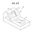
- FIG. 13is perspective view of a combined data reader and EAS system according to an alternate embodiment with deactivation unit(s) disposed in a vertical section of the reader.
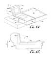
- FIG. 14is perspective view of a combined data reader and EAS system according to an alternate embodiment, the data reader installed in a checkout counter and having multi-dimensional deactivation unit(s).
- FIG. 15is a left side plan view of FIG. 14 .
- FIG. 16is perspective view of a combined data reader and EAS system according to an alternate embodiment with a deactivation unit disposed longitudinally between the horizontal and vertical sections of the reader.
- FIG. 17is a left side plan view of FIG. 16 .
- FIG. 18is perspective view of a combined data reader and EAS system according to an alternate embodiment with a deactivation unit disposed longitudinally at the proximal end of the horizontal section distal from the vertical section.
- FIG. 19is a left side plan view of FIG. 18 .
- FIG. 20is perspective view of a combined data reader and EAS system according to an alternate embodiment with a deactivation unit disposed longitudinally at the upper end of the vertical section distal from the horizontal section.
- FIG. 21is a left side plan view of FIG. 20 .
- FIGS. 22-23illustrate a combined EAS and bar code reader with scale system having two load cells.
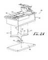
- FIG. 24illustrates another combined EAS and bar code reader with scale system having one load cell.
- FIGS. 1-6illustrate a combined data reader and EAS system 10 according to a first preferred embodiment.
- the system 10includes an outer housing 12 with a lower housing section 20 containing a horizontal window 22 and an upper housing section 40 containing a vertical window 42 .
- the lower housing section 20includes a scale system supporting the weigh platter 30 .
- the weigh platter 30may comprise a single plane, or may comprise multiple planes as described in U.S. Pat. No. 5,834,708 hereby incorporated by reference when the scanner-scale comprises a two-plane or vertical plane scanner.
- the system 10is illustrated as a two-plane scanner with horizontal window 22 and vertical window 42 , the system may alternately comprise a single window, either horizontal or vertical.
- the system 10includes one or two EAS coil units 50 a , 50 b each preferably encased in a plastic enclosure.
- the coil units 50 a , 50 bare each disposed between the weigh platter 30 and the bottom inner scan housing 24 , but laterally outside the horizontal window 22 (that is, to the left or right as from the position of FIGS. 1-2) so as to not interfere with the scan pattern being generated and projected out window 22 .
- Various components of the system 10may be constructed of any suitable material, but are preferably constructed of a plastic or other suitable material that does not interfere with the magnetic fields produced by the coils.
- FIGS. 4-6illustrate the system 10 with portions of the housing removed to better illustrate the internal components.
- the system 10includes a first laser module and collector assembly 58 a disposed on one side of the unit producing a first laser beam directed onto one side of the polygon mirror 59 and a second laser beam and collector assembly 58 b disposed on the other side of the unit from the first assembly 58 a producing a first laser beam directed onto one side of the polygon mirror 59 .
- the first and second reading beamsare scanned by the polygon mirror 59 across pattern mirrors 53 in the lower housing section 20 , usually reflecting off a first (primary) pattern mirror and then a second (secondary) mirror with some of the scan lines being formed by reflection off a third (tertiary) pattern mirror, and then all the scan lines being directed out through one of the windows 22 , 42 projecting a complex scan pattern into the scan volume.
- the only a single laser diodemay be required generating a laser beam which is split by a beam splitter into a first and second reading beams, the first reading beam being directed onto the first side of the polygon mirror 59 and the second reading beam being directed onto the second side of the polygon mirror 59 .
- the system 10 of FIGS. 1-3is illustrated with two coil units 50 a and 50 b , but the system may be operative with one coil unit or two coil units.
- the system 10is provided with only one coil unit.
- the coil unit 50 ais disposed downstream of the scan volume. Items are passed left-to-right over the window 22 and through the scan volume where the scanner reads the optical code.
- the itemis passed through the deactivation field of the coil unit 50 a which is in communication with the scanner and deactivates the EAS tag on the item.
- the systemmay be installed in a checkout counter with the flow of goods going from right-to-left (as viewed in FIGS. 1 - 6 ), with the coil unit 50 b disposed downstream of the scan volume. Items are passed right-to-left over the window 22 and through the scan volume where the scanner reads the optical code.
- the itemis passed through the deactivation field of the coil unit 50 b which is in communication with the scanner and deactivates the EAS tag on the item.
- the other coil unitmay be omitted yielding cost savings.
- the deactivation field and the scan volumemay overlap.
- the systemmay comprise two coil units 50 a , 50 b .
- the coil units 50 a and 50 bcomprise different functions. For example, presuming that the scanner 10 is installed in a checkout counter with the flow of goods going from right-to-left (as viewed in FIGS. 1 - 6 ), the coil unit 50 a is disposed upstream of the scan volume and the coil unit 50 b is disposed downstream of the scan volume. Items are passed right-to-left over the window 22 and through the scan volume where the scanner reads the optical code.
- the downstream coil 50 bmay be configured and operable for deactivating an EAS tag and the upstream coil unit 50 a may be configured and operable to sense an EAS tag.
- the upstream coil 50 asenses the presence of an EAS tag even before the item is scanned thus alerting the system 10 that the item being scanned has an EAS tag. Once the scanner has read the optical code on the item and identified it, in the same motion, the item is passed through the deactivation field of the downstream coil unit 50 b , which has been alerted by the upstream of the presence of the EAS tag, and which deactivates the EAS tag.
- the coil unit 50 amay be physically and electrically integrated into the scanner to a range of varying degrees.
- the unitis disposed laterally in a cavity between the weigh platter and the lower enclosure 24 .
- the unit 50 ais also disposed laterally of the lower window 26 to avoid interfering with the scan beam projected off the lower mirror array and through the lower window 26 .
- the coil unit 50 ais mounted on a mounting bracket or coil mount 56 .
- the coil mount 56is mounted onto a side of the lower enclosure 24 .
- the above-described constructionis just one example for mounting and positioning the coil units 50 a , 50 b .
- the coil units 50 a , 50 bmay be integrated into the lower enclosure 24 or mounted directly thereto.
- the coil units 50 a , 50 bmay be mounted to or even integrated or otherwise incorporated into the platter 30 .
- the coil unit 50 ais preferably constructed to be interchangeable and usable in the position of the unit 50 b .
- FIGS. 7-12illustrate an alternate embodiment for a system 100 in which the deactivator coil units are interchangeable.
- the system 100comprises a two plane scanner in the same configuration as the previous embodiment with a vertical window 142 disposed in the upper housing section 140 and a horizontal window 122 disposed in the weigh platter 130 of the lower housing section 120 .
- the EAS coil unit 150is disposed beneath the weigh platter 130 mounted via the coil mount 156 .
- the system 100may comprise a vertical scanner window 142 only (the lower window 122 omitted) the lower housing section 120 being configured with or without the weigh platter and scale.
- the unitmay comprise a horizontal scanner, with the horizontal window 122 only, the upper housing section 140 being omitted.
- the weigh platter 130is supported by a spider 135 which is operably connected to the load cell 110 .
- the load cellis mounted onto a mounting block 116 to the lower enclosure 124 .
- the coil unit 150is illustrated in FIGS. 7-10 on the right side of the weigh platter 130 , preferable for a left-to-right scanning.
- the spider 135has a U-shaped construction, with the central portion 135 a disposed over the load cell 110 , and a first lateral extension 135 b disposed at the front of the weigh platter 130 and second lateral extension disposed at the rear of the weigh platter 130 .
- FIGS. 11-12illustrate the system 100 of FIGS. 7-10 reconfigured for a right-to-left scanning configuration.
- the coil unit 150 and mount bracket 156have been moved to the left side of the housing.
- the spider 135has also been rotated with the central portion 135 a shifted to the right side of the housing, with the load cell 110 and mount 116 also to the right side of the housing.
- the lateral extensions 135 b and 135 c of the spider 135maintain a support position below the weigh platter 130 and on opposite sides of the coil unit 150 .
- the unit 100may preferably be configured upon ordering at the manufacturer, and then assembled in the selected configuration (left-to-right or right-to-left) as ordered.
- the coil unit 150is connected by a suitable connector, such as an electrical cable, to electronics in the unit 100 such as a printed circuit board disposed in the lower housing section 120 .
- the unitmay be configured in the filed.
- the weigh platter 130is removed to gain access to the other components, and then the coil unit 150 , coil mount 156 , spider 135 , load cell 110 , and bracket 116 are removed.
- the bracket 116is then reinstalled onto the right side and the load cell 110 is mounted to the bracket 116 .
- the spider 135is rotated 180° and secured to the load cell 110 .
- the coil mount 156is installed on the left side and the coil unit 150 reinstalled onto the coil mount.
- the electrical connections to the load cell 110 and coil unit 150are reconnected as required.
- the cablesmay either be provided with alternate cable connection points on the unit or the cables may be of sufficient length to reach the load cell 110 or coil unit 150 in the alternate positions.
- the scale system with load cellis only one example of a scanner-scale configuration.
- the weighing mechanismwould weigh the coil unit(s) along with the weigh platter and any items placed thereon. The weight calibration would then adjust for the additional weight of the coil unit(s) mounted thereon.
- the systemdoes not require the scale and weigh platter.
- scannerssuch as the Magellan® SL scanner are sold in scanner-scale and scanner-only versions.
- the platter of any of the embodimentsmay merely comprise a scanner surface.
- the scannermay comprise a single plane horizontal scanner (with a horizontal window disposed in the counter surface below a scan volume) with the deactivation unit(s) installed therein, or a single plane vertical scanner (with a vertical window disposed to one side of the scan volume) with the deactivation unit(s) installed therein.
- the unitmay be a vertical scanner only with the horizontal window 222 omitted (with or without a weigh platter, or with or without a horizontal section).
- a coil unit 250 ais placed in the upper housing section 240 behind the window 242 on the right side of the section 240 .
- the coil unit 250 ais disposed generally downstream of the scan volume, serving to deactivating an item's EAS tag after the item's optical code has been read by the scanner.
- a coil unit 250 bis placed in the upper housing section 240 behind the window 242 on the left (lateral) side of the section 240 .
- the coil unit 250 bis disposed generally downstream of the scan volume, serving to deactivating an item's EAS tag after the item's optical code has been read by the scanner.
- the enclosure of the units 250 a , 250 bmay be integrated within the upper housing section 240 or may be removably connected on the outer surface of the enclosure.
- the housing section 240may be formed with detents or connectors for accommodating physical mounting and electrical connection of the coil unit 250 .
- the coils units 250 a , 250 bare preferably of the same configuration and interchangeable.
- FIGS. 14-15illustrate yet another configuration for a reader/EAS deactivation unit 300 providing multiplane deactivation.
- the unit 300comprises either a vertical scanner (no horizontal window), or a multiplane scanner (vertical and horizontal windows 342 , 322 ) with housing sections and windows arranged in a generally L-shape.
- the scanner housing 310has (a) an upper housing section 340 , (b) a lower housing section 320 , and (c) an EAS deactivation unit comprised of two parts: (1) a lower unit 350 a disposed in the cavity within the lower housing section 320 below the weigh platter 330 , and to one side of the horizontal window 322 and (2) an upper unit 350 b arranged vertically next to the vertical window 342 in upper housing section 340 .
- the system 300may be configured with a single deactivation unit on one side of the windows 322 , 342 or with two deactivation units, one on either side of the windows 322 , 342 .
- FIGS. 16-17illustrate another configuration for a combined EAS and bar code reader 400 .
- the data reader 410is illustrated as an L-shaped scanner with a lower section 420 containing a horizontal scan window 422 disposed in the horizontal surface or weigh platter 430 , and an upper section 440 containing a vertical scan window 442 .
- the deactivation unit 550is disposed longitudinally along the scan direction of item sweep and in the lower housing section 420 distal from the upper housing section 440 and next to the operator (also know as “checker side”).
- the long axis of the deactivation unit 450is arranged parallel to the direction through items are swept through the scan volume. This configuration may also provide for a single configuration working equally well for right-to-left or left-to-right sweep directions.
- the deactivation field generatedmay more closely match the scan volume, particularly for leading and trailing edges.
- the length of the unit 550may be further extended to extend the deactivation zone enabling items to remain in the deactivation zone for a longer period of time as the item is swept through the scan volume. Such an extended deactivation zone may also more closely match the scan volume for leading and trailing side labels. This position for the deactivation unit 550 may also simplify scale integration.
- FIGS. 20-21illustrate yet another configuration for a combined EAS and bar code reader 600 .
- the data reader 610is illustrated as an L-shaped scanner with a lower section 620 containing a horizontal scan window 622 disposed in the horizontal surface or weigh platter 630 , and an upper section 640 containing a vertical scan window 642 .
- the deactivation unit 650is disposed longitudinally along the direction of product movement and in a top portion of the upper section or bonnet 640 distal from the lower section 620 .
- the long axis of the deactivation unit 650is arranged parallel to the sweep direction in which items are passed through the scan volume. This configuration may also provide for a single configuration working equally well for right-to-left or left-to-right sweep directions.
- the deactivation field generatedmay more closely match the scan volume, particularly for leading and trailing edges.
- the length of the unit 650may be further extended to extend the deactivation zone enabling items to remain in the deactivation zone for a longer period of time as the item is swept through the scan volume. Such an extended deactivation zone may also more closely match the scan volume for leading and trailing side labels.
- the deactivation unit 650is separated from the metal casting and weigh platter 630 so that magnetic field strength may be enhanced. Scale integration may also be simplified.
- additional spaceis provided for the deactivation coil 850 (or multiple coils as in previous embodiments) simplifying construction.
- the additional spacealso simplifies interchangeable configurations such as where the deactivation unit 850 disposed on the left lateral side of the window 822 needs to be switched to the right lateral side.
- the core unitcomprises a block of magnetically active material having a generally rectangular cross-section.
- the coreis about 3 in (7.6 cm) wide, 1.5 in (3.8 cm) deep and 9 in (22.9 cm) long.
- the unitis preferably elongated, having a length at least about three times its width.
- the coremay have a circular or oval cross-section of about 1.5 in (3.8 cm) in diameter.
- the systems describedmay alternately describe not only EAS deactivation units, but also activation units or combined activation/deactivation units usable with activatable EAS tags.
- the EAS tag deactivators/activators describedmay include deactivation or activation of various types of EAS tags such as magnetoacoustic, magnetomechanical, magnetostrictive, RF (e.g. RFID), microwave, and harmonic type tags.
- the deactivation unitsmay comprise coil units with or without internal (magnetically active) core. For example, deactivation coils without internal core are described in U.S. Pat. No. 5,917,412 incorporated by reference.
Landscapes
- Physics & Mathematics (AREA)
- General Physics & Mathematics (AREA)
- Engineering & Computer Science (AREA)
- Electromagnetism (AREA)
- Theoretical Computer Science (AREA)
- Automation & Control Theory (AREA)
- Computer Security & Cryptography (AREA)
- Health & Medical Sciences (AREA)
- General Health & Medical Sciences (AREA)
- Toxicology (AREA)
- Artificial Intelligence (AREA)
- Computer Vision & Pattern Recognition (AREA)
- Cash Registers Or Receiving Machines (AREA)
Abstract
Description
Claims (34)
Priority Applications (6)
| Application Number | Priority Date | Filing Date | Title |
|---|---|---|---|
| US10/062,274US6783072B2 (en) | 2002-02-01 | 2002-02-01 | Combined data reader and electronic article surveillance (EAS) system |
| EP03707659AEP1479054B1 (en) | 2002-02-01 | 2003-01-31 | Combined data reader and electronic article surveillance (eas) system |
| CA2492693ACA2492693C (en) | 2002-02-01 | 2003-01-31 | Combined data reader and electronic article surveillance (eas) system |
| US10/825,444US8011579B2 (en) | 2002-02-01 | 2004-04-14 | Combined data reader and electronic article surveillance (EAS) system |
| US10/985,761US7172123B2 (en) | 2002-02-01 | 2004-11-10 | Combined data reader and electronic article surveillance (EAS) system |
| US11/482,536US7374092B2 (en) | 2002-02-01 | 2006-07-07 | Combined data reader and electronic article surveillance (EAS) system |
Applications Claiming Priority (1)
| Application Number | Priority Date | Filing Date | Title |
|---|---|---|---|
| US10/062,274US6783072B2 (en) | 2002-02-01 | 2002-02-01 | Combined data reader and electronic article surveillance (EAS) system |
Related Child Applications (1)
| Application Number | Title | Priority Date | Filing Date |
|---|---|---|---|
| US10/825,444ContinuationUS8011579B2 (en) | 2002-02-01 | 2004-04-14 | Combined data reader and electronic article surveillance (EAS) system |
Publications (2)
| Publication Number | Publication Date |
|---|---|
| US20030146280A1 US20030146280A1 (en) | 2003-08-07 |
| US6783072B2true US6783072B2 (en) | 2004-08-31 |
Family
ID=27658547
Family Applications (4)
| Application Number | Title | Priority Date | Filing Date |
|---|---|---|---|
| US10/062,274Expired - LifetimeUS6783072B2 (en) | 2002-02-01 | 2002-02-01 | Combined data reader and electronic article surveillance (EAS) system |
| US10/825,444Expired - LifetimeUS8011579B2 (en) | 2002-02-01 | 2004-04-14 | Combined data reader and electronic article surveillance (EAS) system |
| US10/985,761Expired - LifetimeUS7172123B2 (en) | 2002-02-01 | 2004-11-10 | Combined data reader and electronic article surveillance (EAS) system |
| US11/482,536Expired - LifetimeUS7374092B2 (en) | 2002-02-01 | 2006-07-07 | Combined data reader and electronic article surveillance (EAS) system |
Family Applications After (3)
| Application Number | Title | Priority Date | Filing Date |
|---|---|---|---|
| US10/825,444Expired - LifetimeUS8011579B2 (en) | 2002-02-01 | 2004-04-14 | Combined data reader and electronic article surveillance (EAS) system |
| US10/985,761Expired - LifetimeUS7172123B2 (en) | 2002-02-01 | 2004-11-10 | Combined data reader and electronic article surveillance (EAS) system |
| US11/482,536Expired - LifetimeUS7374092B2 (en) | 2002-02-01 | 2006-07-07 | Combined data reader and electronic article surveillance (EAS) system |
Country Status (2)
| Country | Link |
|---|---|
| US (4) | US6783072B2 (en) |
| CA (1) | CA2492693C (en) |
Cited By (23)
| Publication number | Priority date | Publication date | Assignee | Title |
|---|---|---|---|---|
| US20040108383A1 (en)* | 2002-01-11 | 2004-06-10 | Timothy Good | Bioptical laser scanner for six-sided 360 pos-based scanning |
| US20040113791A1 (en)* | 2002-03-18 | 2004-06-17 | Psc Scanning, Inc. | Operation monitoring and enhanced host communications in systems employing electronic article surveillance and RFID tags |
| US20040189472A1 (en)* | 2002-02-01 | 2004-09-30 | Psc Scanning, Inc. | Combined data reader and electronic article surveillance (EAS) system |
| US20050061888A1 (en)* | 2002-01-11 | 2005-03-24 | Metrologic Instruments, Inc. | Bioptical laser scanning system providing 360 degree of omnidirectional bar code symbol scanning coverage at point of sale station |
| US20050098634A1 (en)* | 2000-04-18 | 2005-05-12 | Metrologic Instruments, Inc. | Bioptical laser scanning system providing 360° of omnidirectional bar code symbol scanning coverage at point of sale station |
| US20050126824A1 (en)* | 2002-06-06 | 2005-06-16 | En Novative Technologies, Inc. | Soil sampling system and method that allow headspace screening at spaced intervals without disturbing soil sample |
| US20050145694A1 (en)* | 2002-02-01 | 2005-07-07 | Ncr Corporation | Checkout device including integrated barcode reader, scale, and EAS system |
| US6942145B1 (en)* | 2003-06-11 | 2005-09-13 | Ncr Corporation | Checkout device with enhanced security label detection |
| US20050212673A1 (en)* | 2004-03-24 | 2005-09-29 | Forster Ian J | System and method for selectively reading RFID devices |
| US20050219053A1 (en)* | 2002-02-01 | 2005-10-06 | Psc Scanning, Inc. | Systems and methods for optical reading and EAS tag sensing and deactivating at retail checkout |
| US7021544B1 (en)* | 2004-02-23 | 2006-04-04 | Ncr Corporation | Checkout device including scan pattern-shifting element |
| US20060208894A1 (en)* | 2005-02-08 | 2006-09-21 | Friend Matthew J | Integrated data reader and electronic article surveillance (EAS) system |
| US7341185B1 (en)* | 2007-10-30 | 2008-03-11 | International Business Machines Corporation | Method of marking and monitoring products at a self-service checkout terminal |
| US7389932B1 (en)* | 2006-09-19 | 2008-06-24 | Ncr Corporation | Barcode scanner with tool free tower housing assembly |
| USD601557S1 (en) | 2007-08-06 | 2009-10-06 | Data Ltd., Inc. | Tablet computer |
| USD635568S1 (en) | 2009-06-09 | 2011-04-05 | Data Ltd., Inc. | Tablet computer |
| USD638834S1 (en) | 2009-10-05 | 2011-05-31 | Data Ltd., Inc. | Tablet computer |
| USD654499S1 (en) | 2009-06-09 | 2012-02-21 | Data Ltd., Inc. | Tablet computer |
| US8381979B2 (en) | 2011-01-31 | 2013-02-26 | Metrologic Instruments, Inc. | Bar code symbol reading system employing EAS-enabling faceplate bezel |
| USD690296S1 (en) | 2011-02-01 | 2013-09-24 | Data Ltd., Inc. | Tablet computer |
| USD709888S1 (en)* | 2012-07-02 | 2014-07-29 | Symbol Technologies, Inc. | Bi-optic imaging scanner module |
| USD723560S1 (en)* | 2013-07-03 | 2015-03-03 | Hand Held Products, Inc. | Scanner |
| US8976030B2 (en) | 2012-04-24 | 2015-03-10 | Metrologic Instruments, Inc. | Point of sale (POS) based checkout system supporting a customer-transparent two-factor authentication process during product checkout operations |
Families Citing this family (52)
| Publication number | Priority date | Publication date | Assignee | Title |
|---|---|---|---|---|
| US6575368B1 (en)* | 1996-01-31 | 2003-06-10 | Psc Scanning, Inc. | Multiple aperture data reader for multi-mode operation |
| US7540424B2 (en)* | 2000-11-24 | 2009-06-02 | Metrologic Instruments, Inc. | Compact bar code symbol reading system employing a complex of coplanar illumination and imaging stations for omni-directional imaging of objects within a 3D imaging volume |
| US20020095343A1 (en)* | 2001-01-12 | 2002-07-18 | Barton Steven P. | Apparatus and method for providing point of purchase products |
| US20050167489A1 (en)* | 2001-01-12 | 2005-08-04 | Barton Steven P. | Point of purchase dispensing device with container and method of using same |
| US7185809B2 (en)* | 2001-01-12 | 2007-03-06 | Wm. Wrigley Jr. Company | RF point of purchase apparatus and method of using same |
| CA2480600C (en)* | 2002-04-11 | 2015-04-07 | Sensormatic Electronics Corporation | System and method for managing assets using a portable combined electronic article surveillance system and barcode scanner |
| US7753268B1 (en) | 2002-05-10 | 2010-07-13 | Phoenix Check Cashing, Inc. | System and method for negotiable instrument cashing transaction assistance procedures |
| US6957770B1 (en)* | 2002-05-10 | 2005-10-25 | Biopay, Llc | System and method for biometric authorization for check cashing |
| US7614550B1 (en) | 2002-05-10 | 2009-11-10 | Phoenix Check Cashing, Inc. | System and method for negotiable instrument cashing fee setup by type |
| US7520422B1 (en) | 2002-05-10 | 2009-04-21 | Phoenix Check Cashing, Inc. | System and method for depositing negotiable instruments |
| US20040000591A1 (en)* | 2002-06-28 | 2004-01-01 | Collins Donald A. | Checkout device including integrated barcode reader and EAS system |
| WO2005063037A1 (en)* | 2003-12-30 | 2005-07-14 | Gumlink A/S | Chewing gum comprising biodegradable polymers and having accelerated degradability |
| US7138919B2 (en)* | 2004-02-23 | 2006-11-21 | Checkpoint Systems, Inc. | Identification marking and method for applying the identification marking to an item |
| US7384496B2 (en)* | 2004-02-23 | 2008-06-10 | Checkpoint Systems, Inc. | Security tag system for fabricating a tag including an integrated surface processing system |
| US7704346B2 (en)* | 2004-02-23 | 2010-04-27 | Checkpoint Systems, Inc. | Method of fabricating a security tag in an integrated surface processing system |
| US8099335B2 (en)* | 2004-02-23 | 2012-01-17 | Checkpoint Systems, Inc. | Method and system for determining billing information in a tag fabrication process |
| US7116227B2 (en) | 2004-02-23 | 2006-10-03 | Checkpoint Systems, Inc. | Tag having patterned circuit elements and a process for making same |
| US7119685B2 (en)* | 2004-02-23 | 2006-10-10 | Checkpoint Systems, Inc. | Method for aligning capacitor plates in a security tag and a capacitor formed thereby |
| US20070164845A1 (en)* | 2004-12-21 | 2007-07-19 | Checkpoint Systems, Inc. | System and method for monitoring security systems |
| US7624918B2 (en)* | 2005-02-04 | 2009-12-01 | Philip Morris Usa Inc. | Wireless identification based display |
| US20070158293A1 (en)* | 2005-12-23 | 2007-07-12 | Societe Jas Hennessy Et Compagnie | Bottle package having an EAS label and an advertising label covering the same |
| US7780086B2 (en)* | 2007-06-28 | 2010-08-24 | Symbol Technologies, Inc. | Imaging reader with plural solid-state imagers for electro-optically reading indicia |
| US8505824B2 (en)* | 2007-06-28 | 2013-08-13 | Symbol Technologies, Inc. | Bar code readers having multifold mirrors |
| US20090020612A1 (en)* | 2007-06-28 | 2009-01-22 | Symbol Technologies, Inc. | Imaging dual window scanner with presentation scanning |
| US8662397B2 (en)* | 2007-09-27 | 2014-03-04 | Symbol Technologies, Inc. | Multiple camera imaging-based bar code reader |
| US8878674B2 (en)* | 2007-10-04 | 2014-11-04 | Ncr Corporation | Item checkout device with antenna |
| US7850085B2 (en)* | 2007-10-19 | 2010-12-14 | Ncr Corporation | Barcode scanner with mirror antenna |
| GB2456310B (en)* | 2008-01-10 | 2011-02-16 | Paul Hulin | EAS slim deactivation pad |
| US8113431B2 (en)* | 2008-02-06 | 2012-02-14 | Ncr Corporation | Scale assembly mounting apparatus for an optical scanner |
| US8033461B2 (en)* | 2008-05-08 | 2011-10-11 | Ncr Corporation | Item checkout device and weigh plate with improved electromagnetic field performance |
| US20100001075A1 (en)* | 2008-07-07 | 2010-01-07 | Symbol Technologies, Inc. | Multi-imaging scanner for reading images |
| US20100102129A1 (en)* | 2008-10-29 | 2010-04-29 | Symbol Technologies, Inc. | Bar code reader with split field of view |
| US8479996B2 (en)* | 2008-11-07 | 2013-07-09 | Symbol Technologies, Inc. | Identification of non-barcoded products |
| US20100140357A1 (en)* | 2008-12-09 | 2010-06-10 | Thomas Roslak | Point-of-transaction checkout system |
| USD631478S1 (en) | 2010-01-11 | 2011-01-25 | Datalogic Scanning, Inc. | Weigh platter or cover for a data reader |
| JP2011191930A (en)* | 2010-03-12 | 2011-09-29 | Toshiba Tec Corp | Checkout processor and checkout processing program |
| US8002184B1 (en)* | 2010-08-12 | 2011-08-23 | Symbol Technologies, Inc. | Bi-optical imaging point-of-transaction workstation with recessed upright window |
| US20120105205A1 (en)* | 2010-10-29 | 2012-05-03 | Ncr Corporation | Item checkout device with weigh plate antenna |
| US20120139730A1 (en)* | 2010-12-03 | 2012-06-07 | Metrologic Instruments, Inc. | Electronic article surveillance system |
| US8469272B2 (en) | 2011-03-29 | 2013-06-25 | Metrologic Instruments, Inc. | Hybrid-type bioptical laser scanning and imaging system supporting digital-imaging based bar code symbol reading at the surface of a laser scanning window |
| US8561905B2 (en) | 2011-06-15 | 2013-10-22 | Metrologic Instruments, Inc. | Hybrid-type bioptical laser scanning and digital imaging system supporting automatic object motion detection at the edges of a 3D scanning volume |
| US8794525B2 (en) | 2011-09-28 | 2014-08-05 | Metologic Insturments, Inc. | Method of and system for detecting produce weighing interferences in a POS-based checkout/scale system |
| US8292181B1 (en)* | 2011-06-27 | 2012-10-23 | Ncr Corporation | Apparatus and system for a hybrid optical code scanner |
| US8890693B2 (en) | 2012-03-30 | 2014-11-18 | W G Security Products | Method and apparatus to deactivate EAS markers |
| US9064395B2 (en) | 2012-06-08 | 2015-06-23 | Datalogic ADC, Inc. | Bezel with non-metallic materials for cover or platter for a data reader in a checkout station |
| US9218516B2 (en)* | 2012-06-08 | 2015-12-22 | Datalogic ADC, Inc. | Data reader platter with integral features delineating a data-reading sweep region |
| USD730901S1 (en)* | 2014-06-24 | 2015-06-02 | Hand Held Products, Inc. | In-counter barcode scanner |
| US9947193B2 (en)* | 2016-04-19 | 2018-04-17 | Symbol Technologies, Llc | Electronic article surveillance (EAS) assembly installable in product processing workstation, and method of installation |
| US9892297B2 (en)* | 2016-05-09 | 2018-02-13 | Symbol Technologies, Llc | Arrangement for, and method of, processing products associated with RFID tags and bar code symbols at the same workstation |
| US10062068B1 (en)* | 2017-08-07 | 2018-08-28 | Symbol Technologies, Llc | Checkout workstation |
| WO2024163480A1 (en)* | 2023-01-31 | 2024-08-08 | Walmart Apollo, Llc | Integrated scale system for checkout terminal |
| USD1090140S1 (en) | 2023-01-31 | 2025-08-26 | Walmart Apollo, Llc | Checkout station |
Citations (52)
| Publication number | Priority date | Publication date | Assignee | Title |
|---|---|---|---|---|
| US4141078A (en) | 1975-10-14 | 1979-02-20 | Innovated Systems, Inc. | Library circulation control system |
| US4575624A (en) | 1982-12-01 | 1986-03-11 | Rheinmetall Gmbh | Arrangement for activating and/or deactivating a marker strip having a magnetizable layer |
| US4652863A (en) | 1983-11-11 | 1987-03-24 | Antonson-Avery Ab | Disarmable magnetic anti-shoplifting marker |
| US4745401A (en) | 1985-09-09 | 1988-05-17 | Minnesota Mining And Manufacturing Company | RF reactivatable marker for electronic article surveillance system |
| US4752758A (en) | 1986-07-21 | 1988-06-21 | Minnesota Mining And Manufacturing Company | Demagnetization apparatus for magnetic markers used with article surveilliance systems |
| US4960651A (en) | 1987-06-08 | 1990-10-02 | Scientific Generics Limited | Magnetic devices |
| US5059951A (en) | 1988-11-14 | 1991-10-22 | Checkpoint Systems, Inc. | Method and apparatus for integrated data capture and electronic article surveillance |
| US5103235A (en) | 1988-12-30 | 1992-04-07 | Checkpoint Systems, Inc. | Antenna structure for an electronic article surveillance system |
| US5142292A (en) | 1991-08-05 | 1992-08-25 | Checkpoint Systems, Inc. | Coplanar multiple loop antenna for electronic article surveillance systems |
| US5210524A (en) | 1990-05-16 | 1993-05-11 | Minnesota Mining And Manufacturing Company | Electro-magnetic desensitizer |
| US5225807A (en) | 1991-09-16 | 1993-07-06 | Knogo Corporation | Method and apparatus for sensitizing and desensitizing targets for electronic article surveillance systems |
| US5341125A (en) | 1992-01-15 | 1994-08-23 | Sensormatic Electronics Corporation | Deactivating device for deactivating EAS dual status magnetic tags |
| EP0329402B1 (en) | 1988-02-15 | 1994-12-07 | Esselte Meto International GmbH | Systems and markers using magnetic or spin resonance phenomena |
| US5377269A (en) | 1992-10-29 | 1994-12-27 | Intelligent Security Systems, Inc. | Security access and monitoring system for personal computer |
| US5376923A (en) | 1992-12-14 | 1994-12-27 | Minnesota Mining And Manufacturing Company | On the counter deactivator |
| US5410108A (en) | 1992-08-31 | 1995-04-25 | Spectra-Physics Scanning Systems, Inc. | Combined scanner and scale |
| US5587703A (en) | 1994-10-25 | 1996-12-24 | Dumont; Charles | Universal merchandise tag |
| US5635906A (en) | 1996-01-04 | 1997-06-03 | Joseph; Joseph | Retail store security apparatus |
| US5837988A (en) | 1992-07-14 | 1998-11-17 | Spectra-Physica Scanning Systems, Inc. | Multiple plane scanning system for data reading applications |
| US5841348A (en) | 1997-07-09 | 1998-11-24 | Vacuumschmelze Gmbh | Amorphous magnetostrictive alloy and an electronic article surveillance system employing same |
| US5917412A (en) | 1997-05-21 | 1999-06-29 | Sensormatic Electronics Corporation | Deactivation device with biplanar deactivation |
| US5939984A (en) | 1997-12-31 | 1999-08-17 | Intermec Ip Corp. | Combination radio frequency transponder (RF Tag) and magnetic electronic article surveillance (EAS) material |
| US5955951A (en) | 1998-04-24 | 1999-09-21 | Sensormatic Electronics Corporation | Combined article surveillance and product identification system |
| US5963134A (en) | 1997-07-24 | 1999-10-05 | Checkpoint Systems, Inc. | Inventory system using articles with RFID tags |
| US5978772A (en) | 1996-10-11 | 1999-11-02 | Mold; Jeffrey W. | Merchandise checkout system |
| US5990794A (en) | 1996-09-26 | 1999-11-23 | Sensormatic Electronics Corporation | Apparatus for data communication and deactivation of electronic article surveillance tags |
| US6025780A (en) | 1997-07-25 | 2000-02-15 | Checkpoint Systems, Inc. | RFID tags which are virtually activated and/or deactivated and apparatus and methods of using same in an electronic security system |
| US6102290A (en) | 1988-08-25 | 2000-08-15 | Symbol Technologies, Inc. | Self-checkout, point-of-transaction system including deactivatable electro-optically coded surveillance tags |
| US6114961A (en) | 1999-11-12 | 2000-09-05 | Sensormatic Electronics Corporation | Multi-technology in-line EAS deactivation apparatus |
| US6121878A (en) | 1998-05-01 | 2000-09-19 | Intermec Ip Corp. | System for controlling assets |
| WO2000067193A1 (en) | 1999-05-03 | 2000-11-09 | Psc Scanning, Inc. | Dual ended cable for connecting electronic article surveillance antenna with rfid equipment |
| US6154135A (en) | 1996-09-26 | 2000-11-28 | Sensormatic Electronics Corporation | Apparatus for capturing data and deactivating electronic article surveillance tags |
| US6154137A (en) | 1998-06-08 | 2000-11-28 | 3M Innovative Properties Company | Identification tag with enhanced security |
| US6169483B1 (en) | 1999-05-04 | 2001-01-02 | Sensormatic Electronics Corporation | Self-checkout/self-check-in RFID and electronics article surveillance system |
| US6206285B1 (en) | 1996-10-01 | 2001-03-27 | Siemens Nixdorf Informationssysteme Aktiengesellschaft | Peripheral assembly kit for the workstation of a goods invoicing system |
| US6208235B1 (en) | 1997-03-24 | 2001-03-27 | Checkpoint Systems, Inc. | Apparatus for magnetically decoupling an RFID tag |
| EP1098276A2 (en) | 1999-11-02 | 2001-05-09 | Ncr International Inc. | Apparatus and method for operating a checkout system |
| US6237852B1 (en) | 1995-06-08 | 2001-05-29 | Psc Scanning, Inc. | Multiple plane weigh platter for multiple plane scanning systems |
| US6252508B1 (en) | 1995-10-11 | 2001-06-26 | Motorola, Inc. | Radio frequency identification tag arranged for magnetically storing tag state information |
| US6281796B1 (en) | 1999-10-29 | 2001-08-28 | Sensormatic Electronics Corporation | Point-of sale reader and electronic article surveillance tag deactivator interface |
| US6299702B1 (en) | 1997-11-12 | 2001-10-09 | Vacuumschmelze Gmbh | Method of annealing amorphous ribbons and marker for electronic article surveillance |
| US6335686B1 (en) | 1998-08-14 | 2002-01-01 | 3M Innovative Properties Company | Application for a radio frequency identification system |
| US6346884B1 (en) | 1998-09-25 | 2002-02-12 | Mitsubishi Materials Corporation | Apparatus for identifying an article |
| US6356197B1 (en) | 2000-04-03 | 2002-03-12 | Sensormatic Electronics Corporation | Electronic article surveillance and identification device, system, and method |
| US6497361B1 (en) | 1998-10-15 | 2002-12-24 | Ncr Corporation | Apparatus and method for deactivating electronic article surveillance in a retail self-checkout terminal |
| US6499656B1 (en) | 1998-03-04 | 2002-12-31 | Trolley Scan (Proprietary) Limited | Identification of objects by a reader |
| US20030075602A1 (en) | 2001-10-23 | 2003-04-24 | Ncr Corporation | Automatic electronic article surveillance for self-checkout |
| US6592037B1 (en)* | 1997-09-16 | 2003-07-15 | Meto International Gmbh | Method and device for the detection and deactivation of a deactivatable security element |
| US20030135417A1 (en) | 2002-01-15 | 2003-07-17 | International Business Machines Corporation | Inventory control and point-of-sale system and method |
| US6595421B2 (en) | 2001-01-31 | 2003-07-22 | Ncr Corporation | Integrated antenna scanner window |
| US20030146278A1 (en) | 2002-02-01 | 2003-08-07 | Ncr Corporation | Checkout device including integrated barcode reader, scale, and EAS system |
| US20030197611A1 (en) | 2002-02-01 | 2003-10-23 | Clifford Harold C. | Systems and methods for data reading and EAS tag sensing and deactivating at retail checkout |
Family Cites Families (32)
| Publication number | Priority date | Publication date | Assignee | Title |
|---|---|---|---|---|
| US4964053A (en)* | 1988-04-22 | 1990-10-16 | Checkrobot, Inc. | Self-checkout of produce items |
| US6330973B1 (en)* | 1989-10-30 | 2001-12-18 | Symbol Technologies, Inc. | Integrated code reading systems including tunnel scanners |
| US5139100A (en)* | 1991-02-04 | 1992-08-18 | Point Of Sale Data Products, Inc. | Point-of-sale scanner/scale system with scale activation of scanner |
| DE4319299C1 (en)* | 1993-06-10 | 1994-06-09 | Bizerba Werke Kraut Kg Wilh | Weighing device for supermarket cash till - has code scanner or CCD camera beneath window load platform and carrier for scanning coded price data |
| US5588621A (en)* | 1995-02-23 | 1996-12-31 | At&T Global Information Solutions Company | Universal mounting apparatus and method for bar code scanners |
| US6158662A (en) | 1995-03-20 | 2000-12-12 | Symbol Technologies, Inc. | Triggered optical reader |
| JP3441580B2 (en)* | 1995-12-14 | 2003-09-02 | 富士通株式会社 | Reader |
| US5804807A (en) | 1996-09-12 | 1998-09-08 | Symbol Technologies, Inc. | Scan-ahead system for processing merchandise at a checkout register |
| US5886336A (en)* | 1996-12-12 | 1999-03-23 | Ncr Corporation | Multiside coverage optical scanner |
| US6011474A (en) | 1998-04-28 | 2000-01-04 | Sensormatic Electronics Corporation | Multiple-use deactivation device for electronic article surveillance markers |
| US6085979A (en)* | 1998-06-23 | 2000-07-11 | Ncr Corporation | Off-scale item sensing apparatus and method for a bar code reader |
| EP1770592B1 (en) | 1998-08-14 | 2009-10-07 | 3M Innovative Properties Company | Method of interrogating a package bearing an RFID tag |
| AU769526B2 (en) | 1998-10-30 | 2004-01-29 | Tyco Fire & Security Gmbh | Security systems for inhibiting theft of goods from retail stores |
| DE19908880A1 (en) | 1999-03-01 | 2000-09-07 | Georg Siegel Gmbh Zur Verwertu | Expansion unit for security label deactivation unit for shop etc. has sensor for checking state of security label and indicates e.g. successful deactivation |
| US6333692B1 (en) | 1999-07-06 | 2001-12-25 | Ats Money Systems Inc. | Security tag deactivation system |
| US6857567B2 (en) | 2000-10-17 | 2005-02-22 | Psc Scanning, Inc. | System and method for training and monitoring data reader operators |
| US6396455B1 (en) | 2000-11-14 | 2002-05-28 | Sensormatic Electronics Corporation | Antenna with reduced magnetic far field for EAS marker activation and deactivation |
| US6598791B2 (en) | 2001-01-19 | 2003-07-29 | Psc Scanning, Inc. | Self-checkout system and method including item buffer for item security verification |
| US6429776B1 (en) | 2001-02-07 | 2002-08-06 | Sensormatic Electronics Corporation | RFID reader with integrated display for use in a product tag system |
| US7672871B2 (en) | 2001-02-28 | 2010-03-02 | Fujitsu Frontech North America Inc. | Self-checkout system with anti-theft deactivation device |
| US6507279B2 (en) | 2001-06-06 | 2003-01-14 | Sensormatic Electronics Corporation | Complete integrated self-checkout system and method |
| US6778087B2 (en) | 2001-06-15 | 2004-08-17 | 3M Innovative Properties Company | Dual axis magnetic field EAS device |
| US6783072B2 (en) | 2002-02-01 | 2004-08-31 | Psc Scanning, Inc. | Combined data reader and electronic article surveillance (EAS) system |
| US6778205B2 (en)* | 2002-02-28 | 2004-08-17 | Hewlett-Packard Development Company, L.P. | Methods and apparatuses for forming visible labels on objects using a writable optical disc drive |
| US7527198B2 (en) | 2002-03-18 | 2009-05-05 | Datalogic Scanning, Inc. | Operation monitoring and enhanced host communications in systems employing electronic article surveillance and RFID tags |
| US6764010B2 (en) | 2002-05-10 | 2004-07-20 | Ncr Corporation | Checkout device including barcode reading apparatus, scale, and EAS system |
| US20040000591A1 (en) | 2002-06-28 | 2004-01-01 | Collins Donald A. | Checkout device including integrated barcode reader and EAS system |
| US6788205B1 (en) | 2002-08-30 | 2004-09-07 | Ncr Corporation | System and method for verifying surveillance tag deactivation in a self-checkout station |
| US6809645B1 (en) | 2002-08-30 | 2004-10-26 | Ncr Corporation | System and method for updating a product database based on surveillance tag detection at a self-checkout station |
| US7619527B2 (en) | 2005-02-08 | 2009-11-17 | Datalogic Scanning, Inc. | Integrated data reader and electronic article surveillance (EAS) system |
| US7398918B1 (en)* | 2005-04-04 | 2008-07-15 | American Express Travel Related Services Company, Inc. | Systems and method for risk triggering values |
| US8245926B2 (en) | 2008-11-19 | 2012-08-21 | Datalogic ADC, Inc. | Method of preventing multiple reads when scanning groups of optical codes |
- 2002
- 2002-02-01USUS10/062,274patent/US6783072B2/ennot_activeExpired - Lifetime
- 2003
- 2003-01-31CACA2492693Apatent/CA2492693C/ennot_activeExpired - Lifetime
- 2004
- 2004-04-14USUS10/825,444patent/US8011579B2/ennot_activeExpired - Lifetime
- 2004-11-10USUS10/985,761patent/US7172123B2/ennot_activeExpired - Lifetime
- 2006
- 2006-07-07USUS11/482,536patent/US7374092B2/ennot_activeExpired - Lifetime
Patent Citations (54)
| Publication number | Priority date | Publication date | Assignee | Title |
|---|---|---|---|---|
| US4141078A (en) | 1975-10-14 | 1979-02-20 | Innovated Systems, Inc. | Library circulation control system |
| US4575624A (en) | 1982-12-01 | 1986-03-11 | Rheinmetall Gmbh | Arrangement for activating and/or deactivating a marker strip having a magnetizable layer |
| US4652863A (en) | 1983-11-11 | 1987-03-24 | Antonson-Avery Ab | Disarmable magnetic anti-shoplifting marker |
| US4745401A (en) | 1985-09-09 | 1988-05-17 | Minnesota Mining And Manufacturing Company | RF reactivatable marker for electronic article surveillance system |
| US4752758A (en) | 1986-07-21 | 1988-06-21 | Minnesota Mining And Manufacturing Company | Demagnetization apparatus for magnetic markers used with article surveilliance systems |
| US4960651A (en) | 1987-06-08 | 1990-10-02 | Scientific Generics Limited | Magnetic devices |
| EP0329402B1 (en) | 1988-02-15 | 1994-12-07 | Esselte Meto International GmbH | Systems and markers using magnetic or spin resonance phenomena |
| US6102290A (en) | 1988-08-25 | 2000-08-15 | Symbol Technologies, Inc. | Self-checkout, point-of-transaction system including deactivatable electro-optically coded surveillance tags |
| US5059951A (en) | 1988-11-14 | 1991-10-22 | Checkpoint Systems, Inc. | Method and apparatus for integrated data capture and electronic article surveillance |
| US5103235A (en) | 1988-12-30 | 1992-04-07 | Checkpoint Systems, Inc. | Antenna structure for an electronic article surveillance system |
| US5210524A (en) | 1990-05-16 | 1993-05-11 | Minnesota Mining And Manufacturing Company | Electro-magnetic desensitizer |
| US5142292A (en) | 1991-08-05 | 1992-08-25 | Checkpoint Systems, Inc. | Coplanar multiple loop antenna for electronic article surveillance systems |
| US5225807A (en) | 1991-09-16 | 1993-07-06 | Knogo Corporation | Method and apparatus for sensitizing and desensitizing targets for electronic article surveillance systems |
| US5341125A (en) | 1992-01-15 | 1994-08-23 | Sensormatic Electronics Corporation | Deactivating device for deactivating EAS dual status magnetic tags |
| US5837988A (en) | 1992-07-14 | 1998-11-17 | Spectra-Physica Scanning Systems, Inc. | Multiple plane scanning system for data reading applications |
| US5410108A (en) | 1992-08-31 | 1995-04-25 | Spectra-Physics Scanning Systems, Inc. | Combined scanner and scale |
| US5377269A (en) | 1992-10-29 | 1994-12-27 | Intelligent Security Systems, Inc. | Security access and monitoring system for personal computer |
| US5376923A (en) | 1992-12-14 | 1994-12-27 | Minnesota Mining And Manufacturing Company | On the counter deactivator |
| US5587703A (en) | 1994-10-25 | 1996-12-24 | Dumont; Charles | Universal merchandise tag |
| US6237852B1 (en) | 1995-06-08 | 2001-05-29 | Psc Scanning, Inc. | Multiple plane weigh platter for multiple plane scanning systems |
| US6252508B1 (en) | 1995-10-11 | 2001-06-26 | Motorola, Inc. | Radio frequency identification tag arranged for magnetically storing tag state information |
| US5635906A (en) | 1996-01-04 | 1997-06-03 | Joseph; Joseph | Retail store security apparatus |
| US5990794A (en) | 1996-09-26 | 1999-11-23 | Sensormatic Electronics Corporation | Apparatus for data communication and deactivation of electronic article surveillance tags |
| US6154135A (en) | 1996-09-26 | 2000-11-28 | Sensormatic Electronics Corporation | Apparatus for capturing data and deactivating electronic article surveillance tags |
| US6206285B1 (en) | 1996-10-01 | 2001-03-27 | Siemens Nixdorf Informationssysteme Aktiengesellschaft | Peripheral assembly kit for the workstation of a goods invoicing system |
| US5978772A (en) | 1996-10-11 | 1999-11-02 | Mold; Jeffrey W. | Merchandise checkout system |
| US6208235B1 (en) | 1997-03-24 | 2001-03-27 | Checkpoint Systems, Inc. | Apparatus for magnetically decoupling an RFID tag |
| US5917412A (en) | 1997-05-21 | 1999-06-29 | Sensormatic Electronics Corporation | Deactivation device with biplanar deactivation |
| US5841348A (en) | 1997-07-09 | 1998-11-24 | Vacuumschmelze Gmbh | Amorphous magnetostrictive alloy and an electronic article surveillance system employing same |
| US5963134A (en) | 1997-07-24 | 1999-10-05 | Checkpoint Systems, Inc. | Inventory system using articles with RFID tags |
| US6025780A (en) | 1997-07-25 | 2000-02-15 | Checkpoint Systems, Inc. | RFID tags which are virtually activated and/or deactivated and apparatus and methods of using same in an electronic security system |
| US6592037B1 (en)* | 1997-09-16 | 2003-07-15 | Meto International Gmbh | Method and device for the detection and deactivation of a deactivatable security element |
| US6299702B1 (en) | 1997-11-12 | 2001-10-09 | Vacuumschmelze Gmbh | Method of annealing amorphous ribbons and marker for electronic article surveillance |
| US5939984A (en) | 1997-12-31 | 1999-08-17 | Intermec Ip Corp. | Combination radio frequency transponder (RF Tag) and magnetic electronic article surveillance (EAS) material |
| US6499656B1 (en) | 1998-03-04 | 2002-12-31 | Trolley Scan (Proprietary) Limited | Identification of objects by a reader |
| US5955951A (en) | 1998-04-24 | 1999-09-21 | Sensormatic Electronics Corporation | Combined article surveillance and product identification system |
| US6121878A (en) | 1998-05-01 | 2000-09-19 | Intermec Ip Corp. | System for controlling assets |
| US6154137A (en) | 1998-06-08 | 2000-11-28 | 3M Innovative Properties Company | Identification tag with enhanced security |
| US6335686B1 (en) | 1998-08-14 | 2002-01-01 | 3M Innovative Properties Company | Application for a radio frequency identification system |
| US6346884B1 (en) | 1998-09-25 | 2002-02-12 | Mitsubishi Materials Corporation | Apparatus for identifying an article |
| US6497361B1 (en) | 1998-10-15 | 2002-12-24 | Ncr Corporation | Apparatus and method for deactivating electronic article surveillance in a retail self-checkout terminal |
| WO2000067193A1 (en) | 1999-05-03 | 2000-11-09 | Psc Scanning, Inc. | Dual ended cable for connecting electronic article surveillance antenna with rfid equipment |
| US6517000B1 (en) | 1999-05-03 | 2003-02-11 | Psc Scanning, Inc. | Dual ended cable for connecting electronic article surveillance antenna with RFID equipment |
| US6169483B1 (en) | 1999-05-04 | 2001-01-02 | Sensormatic Electronics Corporation | Self-checkout/self-check-in RFID and electronics article surveillance system |
| US6281796B1 (en) | 1999-10-29 | 2001-08-28 | Sensormatic Electronics Corporation | Point-of sale reader and electronic article surveillance tag deactivator interface |
| EP1098276A2 (en) | 1999-11-02 | 2001-05-09 | Ncr International Inc. | Apparatus and method for operating a checkout system |
| US6114961A (en) | 1999-11-12 | 2000-09-05 | Sensormatic Electronics Corporation | Multi-technology in-line EAS deactivation apparatus |
| US6356197B1 (en) | 2000-04-03 | 2002-03-12 | Sensormatic Electronics Corporation | Electronic article surveillance and identification device, system, and method |
| US6595421B2 (en) | 2001-01-31 | 2003-07-22 | Ncr Corporation | Integrated antenna scanner window |
| US20030075602A1 (en) | 2001-10-23 | 2003-04-24 | Ncr Corporation | Automatic electronic article surveillance for self-checkout |
| US20030135417A1 (en) | 2002-01-15 | 2003-07-17 | International Business Machines Corporation | Inventory control and point-of-sale system and method |
| US20030146278A1 (en) | 2002-02-01 | 2003-08-07 | Ncr Corporation | Checkout device including integrated barcode reader, scale, and EAS system |
| EP1335336A2 (en) | 2002-02-01 | 2003-08-13 | Ncr International Inc. | Checkout device |
| US20030197611A1 (en) | 2002-02-01 | 2003-10-23 | Clifford Harold C. | Systems and methods for data reading and EAS tag sensing and deactivating at retail checkout |
Non-Patent Citations (16)
| Title |
|---|
| Brochure: Magellan SL(TM) 360-Degree Scanner/Scale, PSC Inc. (Feb. 2000). |
| Brochure: Magellan SL™ 360-Degree Scanner/Scale, PSC Inc. (Feb. 2000). |
| Brochure: Mettler Toledo 8217AS Adaptive Scale (1996). |
| Brochure: Mettler Toledo 8217AS Scanner Scale (2003) from http://www.mt.com/mt/product-detail/product.jsp?m=t&key=Y3MDg4NjM1Mj visited Aug. 28, 2003. |
| Brochure: Sensormatic ScanMax(TM) HS Pro Ultra-Max(R) Scanner-Embedded Label Deactivator, Sensormatic Electronics Corporation (2002) http://www.sensormatic.com/EAS/deactivation/slimpad.asp, visited Jul. 29, 2003. |
| Brochure: Sensormatic ScanMax(TM)/SlimPad(TM) Electronic Article Surveillance Deactivator, Sensormatic Electronics Corporation (Jul. 1999). |
| Brochure: Sensormatic ScanMax™ HS Pro Ultra-Max® Scanner-Embedded Label Deactivator, Sensormatic Electronics Corporation (2002) http://www.sensormatic.com/EAS/deactivation/slimpad.asp, visited Jul. 29, 2003. |
| Brochure: Sensormatic ScanMax™/SlimPad™ Electronic Article Surveillance Deactivator, Sensormatic Electronics Corporation (Jul. 1999). |
| Brochure: Sensormatic SlimPad (TM)Pro Ultra-Max(TM) Label Deactivator, Sensormatic Electronics Corporation (2002) Downloaded from http://www.sensormatic.com/EAS/deactivation/slimpad.asp, visited Jul. 29, 2003. |
| Brochure: Sensormatic SlimPad ™Pro Ultra-Max™ Label Deactivator, Sensormatic Electronics Corporation (2002) Downloaded from http://www.sensormatic.com/EAS/deactivation/slimpad.asp, visited Jul. 29, 2003. |
| Installation Guide for Sensormatic Acousto-Link(TM) Option for Ultra-Max Deactivators, Sensormatic Electronics Corporation (2000). |
| Installation Guide for Sensormatic Acousto-Link™ Option for Ultra-Max Deactivators, Sensormatic Electronics Corporation (2000). |
| PSC Scanning, Inc. Magellan SL Scanner and Scanner/Scale Installation and Operation Manual, pp. 1-3 through 1-6 and 2-23 through 2-26 (2001). |
| Sensormatic 2001 Product Catalog, pp. 117-119, 139-145, Sensormatic Electronics Corporation (Jun. 2001). |
| Spectra-Physics VS1000 and VS1200 Scanner Level 1 Service Manual, pp. 4-31 through 4-32 (12/1994). |
| Transponder News, Aug. 14, 2003, http://www.rapidttp.com/transponder/index.html, visited Aug. 20, 2003. |
Cited By (49)
| Publication number | Priority date | Publication date | Assignee | Title |
|---|---|---|---|---|
| US20050098634A1 (en)* | 2000-04-18 | 2005-05-12 | Metrologic Instruments, Inc. | Bioptical laser scanning system providing 360° of omnidirectional bar code symbol scanning coverage at point of sale station |
| US7100832B2 (en)* | 2000-04-18 | 2006-09-05 | Metrologic Instruments, Inc. | Bioptical laser scanning system providing 360° of omnidirectional bar code symbol scanning coverage at point of sale station |
| US7083102B2 (en)* | 2002-01-11 | 2006-08-01 | Metrologic Instruments, Inc. | Bioptical laser scanner for six-sided 360° Pos-based scanning |
| US7383996B2 (en) | 2002-01-11 | 2008-06-10 | Metrologic Instruments, Inc. | Bioptical laser scanner for six-sided 360° POS-based scanning |
| US20040108383A1 (en)* | 2002-01-11 | 2004-06-10 | Timothy Good | Bioptical laser scanner for six-sided 360 pos-based scanning |
| US20050061888A1 (en)* | 2002-01-11 | 2005-03-24 | Metrologic Instruments, Inc. | Bioptical laser scanning system providing 360 degree of omnidirectional bar code symbol scanning coverage at point of sale station |
| US20070029389A1 (en)* | 2002-01-11 | 2007-02-08 | Metrologic Instruments, Inc. | Bioptical laser scanner for six-sided 360º POS-based scanning |
| US7086597B2 (en)* | 2002-01-11 | 2006-08-08 | Metrologic Instruments, Inc. | Bioptical laser scanning system providing 360 degree of omnidirectional bar code symbol scanning coverage at point of sale station |
| US7374092B2 (en) | 2002-02-01 | 2008-05-20 | Datalogic Scanning, Inc. | Combined data reader and electronic article surveillance (EAS) system |
| US20050099300A1 (en)* | 2002-02-01 | 2005-05-12 | Psc Scanning, Inc. | Combined data reader and electronic article surveillance (EAS) system |
| US20050219053A1 (en)* | 2002-02-01 | 2005-10-06 | Psc Scanning, Inc. | Systems and methods for optical reading and EAS tag sensing and deactivating at retail checkout |
| US8011579B2 (en) | 2002-02-01 | 2011-09-06 | Datalogic Scanning, Inc. | Combined data reader and electronic article surveillance (EAS) system |
| US7495564B2 (en) | 2002-02-01 | 2009-02-24 | Datalogic Scanning, Inc. | Systems and methods for data reading and EAS tag sensing and deactivating at retail checkout |
| US20050145694A1 (en)* | 2002-02-01 | 2005-07-07 | Ncr Corporation | Checkout device including integrated barcode reader, scale, and EAS system |
| US20040189472A1 (en)* | 2002-02-01 | 2004-09-30 | Psc Scanning, Inc. | Combined data reader and electronic article surveillance (EAS) system |
| US20070210922A1 (en)* | 2002-02-01 | 2007-09-13 | Psc Scanning, Inc. | Systems and methods for data reading and EAS tag sensing and deactivating at retail checkout |
| US20070063045A1 (en)* | 2002-02-01 | 2007-03-22 | Psc Scanning, Inc. | Combined data reader and electronic article surveillance (EAS) system |
| US7132947B2 (en) | 2002-02-01 | 2006-11-07 | Psc Scanning, Inc. | Systems and methods for data reading and EAS tag sensing and deactivating at retail checkout |
| US7170414B2 (en) | 2002-02-01 | 2007-01-30 | Psc Scanning, Inc. | Systems and methods for optical reading and EAS tag sensing and deactivating at retail checkout |
| US7172123B2 (en) | 2002-02-01 | 2007-02-06 | Psc Scanning, Inc. | Combined data reader and electronic article surveillance (EAS) system |
| US7527198B2 (en)* | 2002-03-18 | 2009-05-05 | Datalogic Scanning, Inc. | Operation monitoring and enhanced host communications in systems employing electronic article surveillance and RFID tags |
| US20100001863A1 (en)* | 2002-03-18 | 2010-01-07 | Salim Mohamed A | Operation monitoring and enhanced host communications in systems employing electronic article surveillance and rfid tags |
| US8006904B2 (en) | 2002-03-18 | 2011-08-30 | Datalogic Scanning, Inc. | Operation monitoring and enhanced host communications in systems employing electronic article surveillance and RFID tags |
| US20040113791A1 (en)* | 2002-03-18 | 2004-06-17 | Psc Scanning, Inc. | Operation monitoring and enhanced host communications in systems employing electronic article surveillance and RFID tags |
| US20050126824A1 (en)* | 2002-06-06 | 2005-06-16 | En Novative Technologies, Inc. | Soil sampling system and method that allow headspace screening at spaced intervals without disturbing soil sample |
| US6942145B1 (en)* | 2003-06-11 | 2005-09-13 | Ncr Corporation | Checkout device with enhanced security label detection |
| US7021544B1 (en)* | 2004-02-23 | 2006-04-04 | Ncr Corporation | Checkout device including scan pattern-shifting element |
| US7088248B2 (en)* | 2004-03-24 | 2006-08-08 | Avery Dennison Corporation | System and method for selectively reading RFID devices |
| US20050212673A1 (en)* | 2004-03-24 | 2005-09-29 | Forster Ian J | System and method for selectively reading RFID devices |
| US8358211B2 (en) | 2005-02-08 | 2013-01-22 | Datalogic ADC, Inc. | Integrated data reader and electronic article surveillance (EAS) system |
| US20060208894A1 (en)* | 2005-02-08 | 2006-09-21 | Friend Matthew J | Integrated data reader and electronic article surveillance (EAS) system |
| US20100148967A1 (en)* | 2005-02-08 | 2010-06-17 | Datalogic Scanning, Inc. | Integrated data reader and electronic article surveillance (eas) system |
| US7619527B2 (en) | 2005-02-08 | 2009-11-17 | Datalogic Scanning, Inc. | Integrated data reader and electronic article surveillance (EAS) system |
| US20080210759A1 (en)* | 2006-09-19 | 2008-09-04 | Roquemore Iii John P | Barcode scanner with tool free tower housing assembly |
| US7556202B2 (en) | 2006-09-19 | 2009-07-07 | Ncr Corporation | Barcode scanner with tool free tower housing assembly |
| US7389932B1 (en)* | 2006-09-19 | 2008-06-24 | Ncr Corporation | Barcode scanner with tool free tower housing assembly |
| USD601557S1 (en) | 2007-08-06 | 2009-10-06 | Data Ltd., Inc. | Tablet computer |
| US7341185B1 (en)* | 2007-10-30 | 2008-03-11 | International Business Machines Corporation | Method of marking and monitoring products at a self-service checkout terminal |
| USD635568S1 (en) | 2009-06-09 | 2011-04-05 | Data Ltd., Inc. | Tablet computer |
| USD654499S1 (en) | 2009-06-09 | 2012-02-21 | Data Ltd., Inc. | Tablet computer |
| USD638834S1 (en) | 2009-10-05 | 2011-05-31 | Data Ltd., Inc. | Tablet computer |
| US8381979B2 (en) | 2011-01-31 | 2013-02-26 | Metrologic Instruments, Inc. | Bar code symbol reading system employing EAS-enabling faceplate bezel |
| US9081995B2 (en) | 2011-01-31 | 2015-07-14 | Metrologice Instruments, Inc. | Bar code symbol reading system employing EAS-enabling faceplate bezel |
| USD690296S1 (en) | 2011-02-01 | 2013-09-24 | Data Ltd., Inc. | Tablet computer |
| US8976030B2 (en) | 2012-04-24 | 2015-03-10 | Metrologic Instruments, Inc. | Point of sale (POS) based checkout system supporting a customer-transparent two-factor authentication process during product checkout operations |
| USD709888S1 (en)* | 2012-07-02 | 2014-07-29 | Symbol Technologies, Inc. | Bi-optic imaging scanner module |
| USD723560S1 (en)* | 2013-07-03 | 2015-03-03 | Hand Held Products, Inc. | Scanner |
| USD766244S1 (en) | 2013-07-03 | 2016-09-13 | Hand Held Products, Inc. | Scanner |
| USD826233S1 (en) | 2013-07-03 | 2018-08-21 | Hand Held Products, Inc. | Scanner |
Also Published As
| Publication number | Publication date |
|---|---|
| US8011579B2 (en) | 2011-09-06 |
| CA2492693A1 (en) | 2003-08-07 |
| US20050099300A1 (en) | 2005-05-12 |
| US20070063045A1 (en) | 2007-03-22 |
| US20040189472A1 (en) | 2004-09-30 |
| US7374092B2 (en) | 2008-05-20 |
| US20030146280A1 (en) | 2003-08-07 |
| CA2492693C (en) | 2013-05-28 |
| US7172123B2 (en) | 2007-02-06 |
Similar Documents
| Publication | Publication Date | Title |
|---|---|---|
| US6783072B2 (en) | Combined data reader and electronic article surveillance (EAS) system | |
| US8358211B2 (en) | Integrated data reader and electronic article surveillance (EAS) system | |
| US6154135A (en) | Apparatus for capturing data and deactivating electronic article surveillance tags | |
| JP5158927B2 (en) | Item checkout device | |
| EP0928472B1 (en) | An apparatus for data communication and deactivation of electronic article surveillance tags | |
| EP2482261B1 (en) | Bar code symbol reading system employing EAS-enabling faceplate bezel | |
| US8976030B2 (en) | Point of sale (POS) based checkout system supporting a customer-transparent two-factor authentication process during product checkout operations | |
| JP2000123251A (en) | Method and system for commodity check-out system | |
| US20040000591A1 (en) | Checkout device including integrated barcode reader and EAS system | |
| US20030209600A1 (en) | Checkout device including barcode reading apparatus, scale, and EAS system | |
| EP1479054B1 (en) | Combined data reader and electronic article surveillance (eas) system | |
| WO2024163480A1 (en) | Integrated scale system for checkout terminal | |
| WO2003065323A2 (en) | Combined data reader and electronic article surveillance (eas) system | |
| US6942145B1 (en) | Checkout device with enhanced security label detection | |
| HK1023436B (en) | An apparatus for data communication and deactivation of electronic article surveillance tags |
Legal Events
| Date | Code | Title | Description |
|---|---|---|---|
| AS | Assignment | Owner name:PSC SCANNING, INC., OREGON Free format text:ASSIGNMENT OF ASSIGNORS INTEREST;ASSIGNORS:ACOSTA, JORGE L.;SVETAL, MICHAEL P.;SALIM, MOHAMED A.;AND OTHERS;REEL/FRAME:012770/0419 Effective date:20020321 | |
| AS | Assignment | Owner name:PSC SCANNING, INC., OREGON Free format text:ASSIGNMENT OF ASSIGNORS INTEREST;ASSIGNOR:PSC SCANNING, INC.;REEL/FRAME:014335/0644 Effective date:20030623 Owner name:SENSORMATIC ELECTRONICS CORPORATION, FLORIDA Free format text:ASSIGNMENT OF ASSIGNORS INTEREST;ASSIGNOR:PSC SCANNING, INC.;REEL/FRAME:014335/0644 Effective date:20030623 | |
| STCF | Information on status: patent grant | Free format text:PATENTED CASE | |
| AS | Assignment | Owner name:PSC SCANNING, INC., OREGON Free format text:ASSIGNMENT OF ASSIGNORS INTEREST;ASSIGNOR:HOSKINSON, JEFFREY J.;REEL/FRAME:016460/0569 Effective date:20050624 | |
| CC | Certificate of correction | ||
| AS | Assignment | Owner name:DATALOGIC SCANNING, INC., OREGON Free format text:CHANGE OF NAME;ASSIGNOR:PSC SCANNING, INC.;REEL/FRAME:020196/0196 Effective date:20070326 | |
| FEPP | Fee payment procedure | Free format text:PAYER NUMBER DE-ASSIGNED (ORIGINAL EVENT CODE: RMPN); ENTITY STATUS OF PATENT OWNER: LARGE ENTITY Free format text:PAYOR NUMBER ASSIGNED (ORIGINAL EVENT CODE: ASPN); ENTITY STATUS OF PATENT OWNER: LARGE ENTITY | |
| FPAY | Fee payment | Year of fee payment:4 | |
| AS | Assignment | Owner name:SENSORMATIC ELECTRONICS, LLC,FLORIDA Free format text:MERGER;ASSIGNOR:SENSORMATIC ELECTRONICS CORPORATION;REEL/FRAME:024213/0049 Effective date:20090922 Owner name:SENSORMATIC ELECTRONICS, LLC, FLORIDA Free format text:MERGER;ASSIGNOR:SENSORMATIC ELECTRONICS CORPORATION;REEL/FRAME:024213/0049 Effective date:20090922 | |
| FPAY | Fee payment | Year of fee payment:8 | |
| AS | Assignment | Owner name:ADT SERVICES GMBH, SWITZERLAND Free format text:ASSIGNMENT OF ASSIGNORS INTEREST;ASSIGNOR:SENSORMATIC ELECTRONICS, LLC;REEL/FRAME:029894/0856 Effective date:20130214 | |
| AS | Assignment | Owner name:TYCO FIRE & SECURITY GMBH, SWITZERLAND Free format text:MERGER;ASSIGNOR:ADT SERVICES GMBH;REEL/FRAME:030290/0731 Effective date:20130326 | |
| FPAY | Fee payment | Year of fee payment:12 | |
| AS | Assignment | Owner name:SENSORMATIC ELECTRONICS, LLC, FLORIDA Free format text:ASSIGNMENT OF ASSIGNORS INTEREST;ASSIGNOR:TYCO FIRE & SECURITY GMBH;REEL/FRAME:047182/0674 Effective date:20180927 | |
| AS | Assignment | Owner name:SENSORMATIC ELECTRONICS, LLC, FLORIDA Free format text:ASSIGNMENT OF ASSIGNORS INTEREST;ASSIGNOR:TYCO FIRE & SECURITY GMBH;REEL/FRAME:047188/0715 Effective date:20180927 |