US6783067B2 - Passport production system and method - Google Patents
Passport production system and methodDownload PDFInfo
- Publication number
- US6783067B2 US6783067B2US09/768,449US76844901AUS6783067B2US 6783067 B2US6783067 B2US 6783067B2US 76844901 AUS76844901 AUS 76844901AUS 6783067 B2US6783067 B2US 6783067B2
- Authority
- US
- United States
- Prior art keywords
- personalization
- passport
- leafing
- document
- module
- Prior art date
- Legal status (The legal status is an assumption and is not a legal conclusion. Google has not performed a legal analysis and makes no representation as to the accuracy of the status listed.)
- Expired - Fee Related, expires
Links
Images


Classifications
- G—PHYSICS
- G06—COMPUTING OR CALCULATING; COUNTING
- G06K—GRAPHICAL DATA READING; PRESENTATION OF DATA; RECORD CARRIERS; HANDLING RECORD CARRIERS
- G06K19/00—Record carriers for use with machines and with at least a part designed to carry digital markings
- G06K19/02—Record carriers for use with machines and with at least a part designed to carry digital markings characterised by the selection of materials, e.g. to avoid wear during transport through the machine
- G06K19/025—Record carriers for use with machines and with at least a part designed to carry digital markings characterised by the selection of materials, e.g. to avoid wear during transport through the machine the material being flexible or adapted for folding, e.g. paper or paper-like materials used in luggage labels, identification tags, forms or identification documents carrying RFIDs
- B—PERFORMING OPERATIONS; TRANSPORTING
- B41—PRINTING; LINING MACHINES; TYPEWRITERS; STAMPS
- B41J—TYPEWRITERS; SELECTIVE PRINTING MECHANISMS, i.e. MECHANISMS PRINTING OTHERWISE THAN FROM A FORME; CORRECTION OF TYPOGRAPHICAL ERRORS
- B41J3/00—Typewriters or selective printing or marking mechanisms characterised by the purpose for which they are constructed
- B41J3/28—Typewriters or selective printing or marking mechanisms characterised by the purpose for which they are constructed for printing downwardly on flat surfaces, e.g. of books, drawings, boxes, envelopes, e.g. flat-bed ink-jet printers
- B41J3/283—Typewriters or selective printing or marking mechanisms characterised by the purpose for which they are constructed for printing downwardly on flat surfaces, e.g. of books, drawings, boxes, envelopes, e.g. flat-bed ink-jet printers on bank books or the like
- B—PERFORMING OPERATIONS; TRANSPORTING
- B42—BOOKBINDING; ALBUMS; FILES; SPECIAL PRINTED MATTER
- B42D—BOOKS; BOOK COVERS; LOOSE LEAVES; PRINTED MATTER CHARACTERISED BY IDENTIFICATION OR SECURITY FEATURES; PRINTED MATTER OF SPECIAL FORMAT OR STYLE NOT OTHERWISE PROVIDED FOR; DEVICES FOR USE THEREWITH AND NOT OTHERWISE PROVIDED FOR; MOVABLE-STRIP WRITING OR READING APPARATUS
- B42D25/00—Information-bearing cards or sheet-like structures characterised by identification or security features; Manufacture thereof
- B42D25/20—Information-bearing cards or sheet-like structures characterised by identification or security features; Manufacture thereof characterised by a particular use or purpose
- B42D25/24—Passports
- B—PERFORMING OPERATIONS; TRANSPORTING
- B42—BOOKBINDING; ALBUMS; FILES; SPECIAL PRINTED MATTER
- B42D—BOOKS; BOOK COVERS; LOOSE LEAVES; PRINTED MATTER CHARACTERISED BY IDENTIFICATION OR SECURITY FEATURES; PRINTED MATTER OF SPECIAL FORMAT OR STYLE NOT OTHERWISE PROVIDED FOR; DEVICES FOR USE THEREWITH AND NOT OTHERWISE PROVIDED FOR; MOVABLE-STRIP WRITING OR READING APPARATUS
- B42D25/00—Information-bearing cards or sheet-like structures characterised by identification or security features; Manufacture thereof
- B42D25/40—Manufacture
- B42D25/405—Marking
- B42D25/41—Marking using electromagnetic radiation
- B—PERFORMING OPERATIONS; TRANSPORTING
- B42—BOOKBINDING; ALBUMS; FILES; SPECIAL PRINTED MATTER
- B42D—BOOKS; BOOK COVERS; LOOSE LEAVES; PRINTED MATTER CHARACTERISED BY IDENTIFICATION OR SECURITY FEATURES; PRINTED MATTER OF SPECIAL FORMAT OR STYLE NOT OTHERWISE PROVIDED FOR; DEVICES FOR USE THEREWITH AND NOT OTHERWISE PROVIDED FOR; MOVABLE-STRIP WRITING OR READING APPARATUS
- B42D9/00—Bookmarkers; Spot indicators; Devices for holding books open; Leaf turners
- B42D9/04—Leaf turners
- B42D9/06—Leaf turners having an arm reset after each operation
- B—PERFORMING OPERATIONS; TRANSPORTING
- B42—BOOKBINDING; ALBUMS; FILES; SPECIAL PRINTED MATTER
- B42D—BOOKS; BOOK COVERS; LOOSE LEAVES; PRINTED MATTER CHARACTERISED BY IDENTIFICATION OR SECURITY FEATURES; PRINTED MATTER OF SPECIAL FORMAT OR STYLE NOT OTHERWISE PROVIDED FOR; DEVICES FOR USE THEREWITH AND NOT OTHERWISE PROVIDED FOR; MOVABLE-STRIP WRITING OR READING APPARATUS
- B42D25/00—Information-bearing cards or sheet-like structures characterised by identification or security features; Manufacture thereof
- B42D25/30—Identification or security features, e.g. for preventing forgery
- B42D25/346—Perforations
Definitions
- This inventionrelates to a system and method for automatically producing secure identity documents.
- this inventionrelates to a system and method for automatically personalizing passports and other secure documents, such as identification cards, as well as printing on and/or personalizing other multiple page, bound documents.
- Machines that personalize passportsare known. These previous machines have included laser engraving capability, but have not included leafing (i.e. page turning) capability. In these machines, the passports are presented individually by hand to the machine, with the passports opened by the operator to the appropriate page for laser engraving of that page. These machines have limited throughput capability, as well as security issues and increased error rates due to operator interaction, making them inadequate for secure, high volume production of passports. In addition, due to the interaction by the operator, passport security issues are present as are increased error rates.
- the inventionprovides a system that is designed to personalize identity documents, such as passports and other multiple page bound documents.
- identity documentssuch as passports and other multiple page bound documents.
- the systempersonalizes each passport with the required information of the intended holder of the passport.
- the inventionalso provides a method of producing identity documents such as passports.
- Required information for passport productioncan include personal biographic data about the passport holder, information concerning the passport holder's family members, emergency information, document holder authentication information, document authentication features, validity period, work status, etc.
- the systemcan also gather information contained on the passport, such as serial number information or pre-printed registration marks for alignment of personaliation information. Detection, or the lack thereof, of this information provides further security.
- the systemeliminates the need for an operator to do many of the steps of passport personalization required by previous machines, such as reading numbers, opening to certain pages, aligning passports with printers, etc.
- operator interventionis required for loading and unloading passports from the input module and the output module, and to clear jams should they occur.
- the systemis preferably modular in construction, thereby readily permitting the assembly and reconfiguration of an application specific production system from different processing modules.
- the modulescan be built and tested prior to configuration into the system. In fact, the modules can be built, tested, packaged and shipped to a job site prior to assembly into a system. Moreover, the modules permit the system to be reconfigured at the job site so as to add or remove modules as dictated by the changing needs of the application.
- a system for personalizing a multiple page, bound documentcomprises a leafing mechanism constructed to receive the bound document in an open or closed configuration.
- the leafing mechanismincludes an apparatus for turning pages of the document.
- the systemfurther includes a personalization mechanism that is disposed either downstream or upstream from the leafing mechanism and which is capable of performing a personalization operation on a page of the document.
- the leafing mechanism and personalization mechanismare constructed as separate modules.
- the personalization modulecan be either a laser personalization module or a printer module.
- the printer modulecan include an integral leafing mechanism built therein. Additional modules can be used within the system as well for performing additional functions. For instance, a second leafing module, one or more input and output modules, an integrated circuit chip module, and one or more additional laser personalization modules and/or printer modules, can be included within the system.
- a leafing mechanismsuch as a leafing apparatus built into the particular personalization module or a separate leafing module, is preferably upstream of each personalization mechanism to permit turning to the appropriate page requiring the next personalization operation.
- a method of personalizing a multiple page, bound documentcomprises inputting a bound document in an open or closed configuration into a leafing mechanism, turning to a preselected page using the leafing mechanism, inputting the document into a personalization mechanism, and performing a personalization operation on the preselected page.
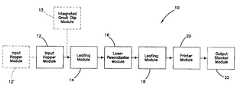
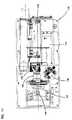
- FIG. 1is a schematic illustration of the passport production system in accordance with the invention.
- FIG. 2is a schematic illustration of an alternate passport production system.
- FIG. 3is a flow chart of steps in the passport production method.
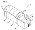
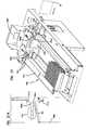
- FIG. 4is a perspective view of a modular passport production system in accordance with the invention.
- FIG. 5is a perspective view of the input hopper mechanism.
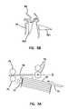
- FIG. 5Aillustrates the entry of a picked passport into transport rollers.
- FIG. 5Billustrates the spring loaded hold down for the passports.
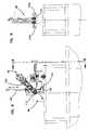
- FIG. 6is a perspective view of the transport and support mechanism used in the leafing module.
- FIG. 7is a top view of the transport and support mechanism used in the leafing module.
- FIG. 8is an end view of the page turning mechanism within the leafing module.
- FIG. 9is a view of the page turning apparatus looking in the direction of line 9 — 9 in FIG. 8 .
- FIG. 10is a perspective view of a portion of the laser personalization apparatus within the laser personalization module.
- FIG. 10Ais a top perspective view illustrating springs holding a passport in place during laser personalization.
- FIG. 11is a top view of the laser system.
- FIG. 12is a sectional side view of the laser system.
- FIG. 13is schematic illustration of the laser paths for the two lasers used in the laser system of the laser module.
- FIG. 14illustrates the laser pulses for the two lasers.
- FIG. 15schematically illustrates the process flow within the printer module.
- FIGS. 16A-Dschematically illustrate passport entry, vertical lifting, leafing and opening in the printer module.
- FIG. 17illustrates a roller system designed to accommodate a different thickness on each half of the passport.
- FIG. 18schematically illustrates the principles behind the roller system of FIG. 17 .
- FIGS. 19A and 19Billustrate the roller system accommodating different passport thickness.
- FIG. 20schematically illustrates vertical dropping and partial closing of the passport after printing.
- FIG. 21is a perspective view of the output stacker mechanism.
- FIG. 21Ais a top view of the gate in the output stacker mechanism.
- FIG. 22illustrates a control strategy for the system.
- FIG. 23illustrates a hardware layout for the system.
- FIG. 1A preferred embodiment of a passport production system 10 according to the invention is schematically illustrated in FIG. 1 .
- the system 10includes an input hopper module 12 , a leafing module 14 , a laser personalization module 16 , a second leafing module 18 , a printer module 20 and an output stacker module 22 .
- the leafing modules 14 and 18are preferably of the same design, although the design can be different if desired.
- the leafing module 18 and the printer module 20are preferably combined into a single module 24 that performs the functions of both the leafing module 18 and the printer module 20 .
- an image perforation module for putting holes in one or more of the passport pagescan be optionally employed in addition to the laser personalization module 16 .
- an integrated circuit chip module 13shown in dashed lines in FIG. 1, for programming an integrated circuit chip, either of the contact type or of the contactless type, that is mounted to a page of the passport can be provided.
- the module 13is preferably one of the first modules in the system 10 to permit an initial determination of whether the integrated circuit chip is functioning. If it is determined that the chip is not functioning, there is no need to perform other personalization procedures on the passport and the passport can be passed through the system to a passport reject location.
- the integrated circuit chip programming apparatuscan be built into one of the other modules, such as the leafing module 14 or the laser personalization module 16 .
- Other modulescan include an encoding module for encoding a magnetic stripe on one or more of the pages of a passport, and/or an embossing module for performing embossing operations on one or more passport pages.
- a vision modulethat is provided with a camera system for displaying an image of one or more of the personalized passport pages can also be provided. Display of the image by the vision module permits a check of the quality and accuracy of the personalization on each page, as well as functioning as part of an alignment system for achieving alignment of the passport page and the respective personalization module.
- a similar vision systemis disclosed in copending U.S. patent application Ser. No. 09/362,197.
- the system 10can be configured with one or more of any of the modules described herein (e.g. two input hopper modules, three laser personalization modules, etc.), and the modules can be physically arranged in any order.
- the modulescan be physically arranged in any order.
- the input hopper module 12is designed to hold a plurality of passports therein waiting to be personalized.
- the passportsare held in a closed configuration in the module 12 , with the spines of the passports oriented either upward or downward. In the preferred arrangement, the spines are oriented downward. Further, the passports are preferably oriented so that the front of each passport faces forward.
- the input hopper module 12is capable of picking a single passport for transport to the next module.
- the leafing module 14receives the closed passport from the input hopper module 12 (or other type of module), and turns the pages of the passport to the appropriate page.
- a suitable systemis provided within the module 14 so that the module 14 knows which page to turn to. For instance, an optical system that reads a passport number on each page can be utilized to detect the passport pages.
- the module 14includes page turning capability to turn the pages of the passport, and a suitable system to enable the module 14 to determine when the desired page has been reached.
- the leafing module 14further has the capability of closing an opened passport and transporting the closed passport to the next module.
- the laser personalization module 16is provided with a laser system capable of performing laser personalization.
- Laser personalization as used hereinincludes engraving, perforating, and bubbling a suitable page of the passport using the laser system.
- the laser system within the module 16in the preferred embodiment, is a dual laser system that enables an approximate doubling of the speed of the laser personalization process compared to a system where only one laser is used.
- the passportmay be transported, opened or closed, to the next module, such as the leafing module 18 /printer module 20 (or the combined leafer and printer module 24 ).
- the passportis turned to the page(s) where printing is to occur, and then the printer performs a printing operation. If printing is not necessary, the passport can be transported through the module without printing.
- the personalized passportmay be closed and then transported to the output stacker module 22 where it is stacked with other, previously personalized passports.
- the module 22can direct the passport to a reject location if it is determined that the passport has been improperly personalized, a bad integrated circuit chip is present, or another defect, either in the personalization processing or in the passport material, is detected.
- FIG. 3illustrates exemplary steps in the method of passport production according to the invention.
- the input hopper moduleis loaded with passports to be personalized and the system controller has been set-up with the necessary information concerning the personalization operations to be performed on the passports
- one of the passportsis picked from the front of the stack in the input hopper module at step 30 .
- the passportis transported to the leafing module 14 , and at step 32 , the passport is turned to the appropriate page. Once the passport is turned to the correct page, the passport is transported to the laser personalization module, where the appropriate page is laser personalized 34 . After laser personalization, the passport is transported to the next module. If printing is necessary, the passport is turned to the appropriate page and printing occurs 36 . After printing (or after laser personalization if printing is not necessary), the passport is closed, and the passport is then transported to the output stacker module where it is collected 38 with other personalized passports.
- passportand “book” are used interchangeably herein to refer to a passport provided with cover pages and a plurality of internal pages.
- cover pagesare generally formed from a thick paper material, while the internal pages are formed from a thinner paper material.
- pageis intended to encompass a cover page as well as an internal page.
- a polycarbonate page of known constructionis suitably secured to the inside surface of one of the cover pages.
- Laser personalizationincluding engraving, perforation and bubbling, occurs primarily on the polycarbonate page, although laser personalization in the form of perforation can occur on the internal paper pages as well.
- Printingoccurs on the internal paper pages, and not on the polycarbonate page which is not generally receptive to printing.
- the number of pages, and the resulting thickness, of a passportvaries by country, and the system 10 is designed to account for the differing passport thickness used by each country.
- FIG. 4illustrates the system 10 including the input hopper module 12 , the leafing module 14 , the laser personalization module 16 , the combined leafer and printer module 24 , and the output stacker module 22 .
- the module 24could consist of a separate leafing module 18 and a separate printer module 20 .
- the system 10further includes a system controller 40 which controls operation of the system 10 , a CRT display 42 for displaying system information and a keyboard 44 for entering control inputs.
- the keyboard 44can be provided with biometric authentication capability so that only authorized personnel can operate the system 10 .
- An additional cabinet 45is provided that holds laser support equipment, such as laser power supplies, for operating the laser personalization module 16 .
- An additional CRT display and input device(not shown) can be provided on the cabinet 45 for use in implementing a camera alignment system described later herein.
- Each of the modules in the system 10can be provided with a global positioning (GPS) mechanism to deter theft of the modules. The GPS mechanism would disable its respective module and prevent its operation if the module were moved too far from a predetermined location.
- GPSglobal positioning
- the input hopper module 12is shown to include a passport receptacle 50 for holding a plurality of passports 52 .
- the receptacle 50includes a bottom support plate 54 with side rail members 66 , a first side wall 56 and a second side wall 58 .
- the bottom support plate 54is fixed on a support table 60 fixed within the module 12 .
- a rod 62extends along the length of the support plate 54 , parallel to the side wall 56 , and a pusher plate 64 is sidably supported on the rod 62 for sliding movements therealong.
- a support bearing 63is mounted on the lower end of the pusher plate 64 and rolls along the top surface of the bottom support plate 54 to rotationally support the pusher plate 64 as it rests against the passports 52 .
- the pusher plate 64is moveable in the direction of the axis A.
- the pusher plate 64is preferably biased by a suitable biasing mechanism, such as a spring, toward the passports 52 , so that the passports 52 are constantly urged toward a discharge position.
- a retention plate 68is fixed to the top of the side wall 56 such that the plate 68 is disposed closely adjacent to the upper edges of the passports 52 in order to keep the passports from sliding upward away from the bottom support plate 54 .
- the side wall 56is flexibly mounted and biased toward the passports 52 so that during the loading of additional passports 52 a the side wall 56 moves away from the passports 52 as the additional passports 52 a are moved downward onto the receptacle 50 , as shown in FIG. 5 B.
- the side wall 56 and plate 68can be mounted so as to slide sideways when loading passports.
- a picker mechanism 70is disposed adjacent to the forward end of the receptacle 50 for picking one of the passports 52 .
- the picker mechanism 70includes a picker 72 that is actuatable in the direction of the arrow in FIG. 5 .
- the picker 72is designed to engage with and drive the forwardmost passport 52 toward and past the end of a stop bar 74 and into transport rollers 76 , shown in FIG. 5A, for transport to the next module.
- the receptacle 50is disposed at an angle ⁇ to a centerline B of the table 60 . Therefore, the movement of the passport 52 as it is picked by picker 72 is disposed at an angle to a transport direction C (see FIG. 5 A).
- Disposing the receptacle 50 at an angleis important as it places the passports 52 initially out of the transport path C, but at the same time directs the passport 52 , as it is picked, toward the nip of the transport rollers 76 . Disposing the receptacle 50 at an angle also allows for the inclusion of intermediate transport rollers 75 for the purpose of moving the passport 52 from the right side of the input hopper module 12 to the transport rollers 76 . This arrangement provides for a transport path very close to the axis C for most reliable movement of the passport 52 . Since the passports 52 or picker mechanism 70 do not block the transport path C, one or more additional input hoppers 12 ′ (shown in dashed lines in FIG. 1) can be utilized upstream of the input hopper 12 . The passports from the additional upstream hopper(s) can therefore be fed along the transport path C without interference from the passports 52 in the hopper 12 .
- the passport 52is transported by the rollers 76 and other suitable transport mechanisms to the leafing module 14 .
- the passports 52are disposed within the hopper 12 with their spines facing downward, so that they are transported to the leafing module with their spines oriented downward.
- Another feature of the input hopper module 12is the ability to read a barcode or other symbol on the passport 52 while the passport 52 is still in the receptacle 50 and before picking takes place.
- a barcode reader 67 or other symbology recognition deviceis disposed adjacent to the passport path so that the reader 67 is able to read a barcode placed on a portion of the passport that is near an upper guide 69 . It is also possible to read a barcode on the passport 52 after it has been picked from the receptacle 50 , or to read a passport that has been received from an upstream module and is in the process of being transferred through the input hopper module 12 .
- Various sizes of passports 52are accommodated by the input hopper module 12 by adjusting the distance between the side rail members 66 , by adjusting the distance between the upper guide 69 and table 60 , and by adjusting the position of the stop bar 74 relative to the forwardmost passport 52 .
- FIGS. 6-9illustrate the details of the leafing module 14 .
- the leafing module 14generally includes a transport and support mechanism 80 (FIGS. 6 and 7) and a page turning mechanism 82 (FIGS. 8 and 9) that function together to open the passport 52 to the appropriate page.
- the transport and support mechanism 80includes a set of input rollers 84 that receive the passport 52 and feed it into the leafing module 14 .
- a wall 86is disposed downstream from the rollers 84 .
- the wall 86provides a surface against which the passport 52 is pressed during the passport opening and page turning procedures.
- a drive belt 88extends around a pulley 89 adjacent to the input rollers 84 , the wall 86 and a pulley 90 disposed at the opposite end of the wall 86 .
- the belt 88further extends around a drive pulley 92 that is driven by a motor 94 whereby the belt 88 is driven by the motor 94 .
- a tab 96extends from the belt 88 , and is provided to engage the trailing edge of the passport 52 after the rollers 84 substantially drive the passport 52 into the leafing module 14 .
- the belt 88 and the tab 96take the passport 52 from the rollers 84 and drive it into position in front of the wall 86 .
- the page turning mechanism 82is positioned generally opposite the wall 86 .
- the page turning mechanism 82includes an arm 100 that extends toward the wall 86 .
- a shaft 102is rotatably mounted.
- An eccentric roller 104 a , 104 bis mounted at each end of the shaft 102 .
- each of the rollers 104 a , 104 bincludes an eccentric portion that extends farther away from the axis of the shaft 102 than the opposite portion of the rollers 104 a , 104 b , whereby during one revolution of the rollers 104 a , 104 b , the eccentric portion thereof will engage with the passport 52 and “pick-up” the cover page or one internal page 106 thereof.
- the rollers 104 a , 104 bare eccentric, the opposite side of each roller 104 a , 104 b will rotate past the passport without engaging any additional pages of the passport 52 while the page just “picked-up” is being moved to the other side of the rollers 104 a , 104 b .
- the rollers 104 a , 104 bpick up the passport cover page or one internal page to start the passport page turning procedure.
- the passportis oriented generally vertically against the wall 86 , and the internal pages or cover page thereof are picked-up by the rollers 104 a , 104 b and moved downward toward a table 110 .
- the page turning mechanism 82also includes a press mechanism 108 that is vertically moveable up and down as indicated by the arrow in FIG. 8 .
- the press mechanism 108is intended to press the page(s) 106 (or the passport cover page) downward against the table 110 after the page(s) 106 has been picked-up by the rollers 104 a , 104 b .
- the press mechanism 108is initially raised upward, and then the rollers 104 a , 104 b pick-up the page 106 , and then the press mechanism 108 is moved down to force the passport 52 to an open position.
- the press mechanism 108is actuated after the desired number of pages have been turned just prior to sending the passport 52 to the next module.
- FIG. 8shows the wall 86 as including an angled surface 112 against which the edge of the passport (i.e. the edge opposite the spine) is pressed.
- the angled surface 112facilitates the opening and page turning functions by making it easier for the rollers 104 a , 104 b to “pick-up” one page at a time.
- a bar 114(best seen in FIG. 6) is pivotally mounted on the table 110 for movement between the vertical position shown in FIG. 6 and a horizontal position flush with the table 110 .
- the bar 114is actuated by an actuator 116 , shown in dashed lines in FIG. 7, disposed underneath the table 110 .
- the bar 114is positioned as shown in FIG. 6 so that the passport is clamped in the area of the spine.
- the bar 114is flush with the table 110 .
- the turning mechanism 82is moved away from the passport 52 so that the pages of the passport can pivot up, and the bar 114 is pivoted upward to its vertical position by the actuator 116 , which forces the passport 52 to a closed position.
- the leafing module 14is capable of turning to any page within the passport 52 .
- a camera system built into the leafing moduleis used to read a marker, such as passport number, provided on each page.
- the passport numbercan be either punched or printed onto each page.
- the passport numberis preferably used as a key by the system to capture personal data keyed to the passport number that is suitably stored by the system for later use in the laser personalization process.
- a marker other than a passport numbercan be read by the camera system, as long as the marker provides an indication of the particular page, so that when the marker is read, the system knows which page is open.
- the ability to be able to ascertain the page number and to turn to any pageis important, since each application may have unique passport requirements. For instance, one application may require that page 3 of the passport 52 be provided with a laser engraved image, while a second application may require that the laser engraved image be provided on a different page. Therefore, the leafing module 14 must be able to turn to the appropriate page.
- the belt 88is again driven to drive the now opened passport 52 out of the leafing module 14 and to the laser personalization module 16 for laser personalizing the page.
- the leafing module 14is designed to permit exit of the opened passport without interfering with the passage thereof.
- the passportcan be transferred through the leafing module 14 either in an open or closed configuration, without turning any pages thereof.
- FIG. 10illustrates a portion of the laser personalizing mechanism 17 used in the laser personalization module 16 .
- the laser personalization mechanism 17includes a support table 120 for supporting the horizontal part of the opened passport 52 , input rollers 122 , and a belt 124 and tab 126 similar to the belt 88 and tab 96 used in the transport and support mechanism 80 of the leafing module 14 .
- the input rollers 122serve to drive the opened passport into the laser personalization module 16 , with the belt 124 and tab 126 functioning to position the passport 52 centrally on the table 120 as shown in dashed lines in FIG. 10 .
- the tab 126like the tab 96 , engages the trailing edge of the passport 52 to push it into position.
- the belt 124is driven by a motor 128 mounted on the table 120 .
- a wall 130extends upwardly from the table 120 for supporting the vertical part of the opened passport 52 .
- FIG. 10Aillustrates a system for holding the passport 52 in place during laser personalization.
- the wall 130includes a flange 200 adjacent the top thereof.
- Mounted to the flange 200are a pair of flat spring elements 202 a , 202 b , each of which are connected at one end to the top of the flange 200 , with the opposite free ends curling around the end of the flange 200 and extending underneath the flange 200 .
- the spring elements 202 a , 202 bare designed to engage the top edge of the vertical portion of the open passport 52 and hold the passport 52 down against the table 120 during personalization.
- a spring element 204 in the form of a wirehas opposite ends 206 , 208 suitably fixed to the spring elements 202 a , 202 b (or to the flange 200 ), and a central pressing portion 210 .
- the spring element 204is constructed and positioned so that the pressing portion 210 presses the vertical portion of the opened passport back against the wall 130 .
- Another spring element 212includes an end 214 that is fixed to the table 120 and a free end region 216 that is constructed and positioned to press the bottom region of the vertical portion of the opened passport 52 back against the wall 130 , as well as hold the passport 52 down against the table 120 .
- the spring elements 202 a , 202 b , 204 and 212thus hold the passport 52 in position during laser personalization, thereby improving the personalization process.
- the spring elements 204 , 212 adjacent the entrance end of the table 120 and wall 130are designed to permit the vertical portion of the opened passport to slide behind the spring elements 204 , 212 when the opened passport is driven into the module 16 . Further, the spring elements 204 , 212 readily permit the tab 126 on the belt 124 to drive the passport from the module once laser personalization is completed.
- an edge 218 of the horizontal portion of the passportslides underneath a ledge 220 provided on the table 120 as the opened passport is driven into the module 16 .
- the ledge 220prevents the edge 218 of the passport from popping upward.
- a laser system 132is suitably mounted adjacent to the table 120 for projecting laser pulses toward the wall 130 and the vertical portion of the passport 52 supported thereby, in order to perform the laser personalization.
- FIGS. 11 and 12illustrate the details of the laser system 132 .
- the laser system 132utilizes a pair of lasers 134 , 136 that are operated out of phase from each other during the laser personalization process. The use of two lasers 134 , 136 operated out of phase permits an approximate doubling of the speed of the laser personalization process compared to the use of a single laser.
- the laser system 132includes a prism 138 for combining the laser beams from the two lasers 134 , 136 , a beam expander 140 for increasing the diameter of the laser beam(s), a mirror 142 for deflecting the laser beam(s), a pair of positionable deflecting mirrors 144 and a lens 146 .
- the lasers 134 , 136are arranged side-by-side, and therefore an additional deflecting mirror 148 is provided to deflect the pulses from laser 134 into the optical path 137 , as shown in FIG. 13 .
- the prism 138is coated such that the laser beam from the laser 134 is reflected and sent in the direction of the beam expander 140 while the laser beam from the laser 136 passes directly through the prism 138 and to the beam expander 140 .
- the phase relationship of the laser beam output pulses P 1 and P 2 from the lasers 134 , 136are illustrated in FIG. 14 .
- the deflecting mirrors 144be positionable to permit laser personalization at any location on the passport page.
- a registration processis employed to register the laser system with the pre-printed fields.
- the registration processutilizes a camera system to view the page of the passport and identify the location of the pre-printed fields with respect to the laser system. Appropriate adjustments are then made to the locations of the laser output to register with the desired pre-printed field.
- the laser personalization module 16employ a correction system to eliminate image distortions from optical components such as mirrors and lenses.
- a correction algorithmis used to adjust the position of the deflecting mirrors 144 during laser personalization such that image distortions are reduced or eliminated.
- the laser personalization module 16could be designed to be able to close the passport 52 after laser personalization is complete.
- a pivoting closing flap 222(illustrated in dashed lines in FIG. 10) similar to the closing mechanism used in the leafing module 14 , is preferably incorporated onto the table 120 to accomplish the closing. Other closing mechanisms could be used as well.
- the belt 124is driven by the motor 128 so that the tab 126 is engaged with the trailing edge of the passport, thereby moving the passport 52 out of the laser personalization module 16 , and into the next module which in the preferred embodiment is the leafer/printing module 24 or the leafing module 18 if a separate leafing module is used.
- the table 120is designed to permit unobstructed movement of the passport 52 .
- the leafer/printing module 24will now be described in reference to FIGS. 15-20. As described above, the module 24 combines the functions of separate leafing and printing modules 18 , 20 . Although the preferred embodiment is described in relation to the module 24 , it is to be realized that separate leafing and printing modules 18 , 20 could be used instead of the combined leafer/printer module 24 .
- the leafer/printing module 24is designed to receive the passport from the laser personalization module, lift the passport upward, turn the pages of the passport 52 to the next appropriate page that is to receive personalization in the form of printing, fully open the passport to a generally flat configuration, perform printing, lower the passport downward and return the passport to its ninety degree, partially open orientation, and either discharge the passport if printing is complete, or return the passport to the leafer function in the leafer/printer module 24 to turn to a new page needing printing.
- the partially opened passport 52enters the module 24 from an upstream module, preferably the laser personalization module 16 , via an input mechanism that includes input rollers 230 .
- the passport 52enters onto a lift mechanism that includes a table 232 .
- the table 232is thereafter lifted upwards to bring the passport to a leafing and opening area where the passport is turned to the appropriate page and then fully opened to a flat orientation.
- FIGS. 16A-DThe mechanisms for page turning and fully opening the passport are illustrated in FIGS. 16A-D.
- FIG. 16Aillustrates the passport 52 in its partially open configuration, before it is lifted upward by the table 232 .
- a leafing mechanism 234is provided that moves up and down with the table 232 .
- the leafing mechanism 234includes an arm 236 that extends toward the horizontal portion of the passport.
- Rotatably mounted on the end of the arm 236is a pair of eccentric rollers 238 that are driven by a motor 240 disposed at the opposite end of the arm 236 .
- the rollers 238are designed to pick-up and turn one page from the horizontal portion to the vertical portion of the passport each time the rollers 238 rotate one clockwise revolution, similar to the rollers 104 a , 104 b in the leafing module 14 .
- FIG. 16Billustrates the passport 52 after it is lifted upwardly by the table 232 .
- the passportremains in its partially open configuration, ready for leafing or page-turning.
- the passportis now positioned relative to an opening bar 242 that is pivotally mounted to fixed structure within the module 24 .
- the opening bar 242is designed to rotate or pivot in the direction of the arrow in FIG. 16B at the appropriate time to engage the vertical portion of the passport and fully open the passport.
- the bar 242includes a portion that extends parallel to the spine of the passport, so that it is able to engage the vertical portion of the passport as the bar 242 is pivoted counterclockwise.
- FIG. 16CThe leafing or page-turning operation is illustrated in FIG. 16C, in which the rollers 238 are rotated by the motor 240 , thereby picking up one sheet 244 (illustrated in dashed lines) of the passport and moving the sheet 244 to a position against the vertical portion of the passport. Rotation of the rollers 238 is repeated until the page requiring printing is reached. Once the appropriate page is reached, the opening bar 242 is pivoted counterclockwise, as shown in FIG. 16D, thereby forcing the vertical portion of the passport down, thereby fully opening the passport to a generally flat orientation.
- a pusher 246is actuated in the direction of the arrow to push the passport toward the nip of rollers 248 , 250 .
- rollers 248 , 250There are a plurality of each roller 248 , 250 (the rollers 248 , 250 extend into and out of the plane of the figure) whereby the rollers 248 , 250 extend across and engage the majority of the passport.
- the rollers 250which are described in detail with respect to FIGS. 17-19, are mounted for movement toward and away from the rollers 248 , as illustrated in dashed lines in FIG. 15 .
- the rollers 248are rotatably mounted to support structure with respect to a print head 252 in the module 24 and are freely rotatable upon the open pages of the passport as the passport is driven between the rollers 248 , 250 .
- the rollers 250Prior to actuating the pusher 246 , the rollers 250 are moved away from the rollers 248 , thereby increasing the size of the nip and facilitating entry of the leading edge of the passport into the nip. Once the leading edge of the passport is positioned in the nip, as shown in dashed lines, the rollers 250 are then moved back toward the rollers 248 to pinch the passport therebetween. Movement of the rollers 250 toward and away from the rollers 248 can be accomplished using a suitable drive mechanism of the type generally known in the art. This movement and actuation of the rollers 250 is different from the independent adjustment motion described supra.
- the print head 252preferably an ink jet print head, prints personalization information onto the page(s) of the passport 52 as the passport is fed by the rollers 248 , 250 .
- the printer utilized with the system 10is preferably an ink-jet printer with the capability of printing in black and in color.
- the ink-jet printeralso has the capability to print many types of images including photos.
- the ink-jet printer that is usedis preferably of the piezo-electric type for improved resolution. Piezo-electric technology in printers is known in the art.
- a registration processmay be employed in the module 24 in order to ensure that the printing is aligned with pre-printed fields on the page to be printed on.
- a difficulty encountered when printing on passports and other bound documentsis that when the passport is fully open to the page(s) requiring printing, one half of the opened passport may have more pages and thus a larger thickness than the other half of the passport.
- this difference in thicknesscan cause difficulties with the printing process because the thicker half of the passport will be closer to the print head 252 than the thinner half of the passport is.
- This difference in spacing from the print head 252results in differences in print quality on the two halves of the passport.
- An additional difficultyis the presence of the spine of the passport, which tends to cause the pages of the passport adjacent the spine to bulge upward when the passport is fully opened. This bulging of the pages adjacent to the spine also affects the print quality, particularly adjacent to the spine.
- the rollers 250 in the module 24are designed to be self-adjusting to account for the different thickness on each passport half, and to accommodate the spine of the passport with minimal bulging.
- FIG. 17illustrates the rollers 250 , each of which is provided with an outer coating containing grit particles to form a high friction surface. Alternatively, the rollers 250 could be coated with an elastomer such as rubber or another material with suitable surface friction qualities.
- Each roller 250is separately rotatably mounted on an H-shaped support 254 a , 254 b .
- a gap 256 between the ends of the rollers 250 and the supports 254 a , 254 baccommodates the spine of the passport which is illustrated in phantom line in FIG. 17 .
- each support 254 a , 254 bis pivotally mounted on a shaft 258 whereby the rollers 250 can pivot towards and away from the rollers 248 through the pivoting motion of the supports 254 a , 254 b about the shaft 258 .
- Bias springs 260are disposed around the shaft 258 and each spring 260 includes one end engaged to fixed structure of the module 24 and an opposite end engaged with the support 254 a , 254 b whereby the supports 254 a , 254 b , and thereby the rollers 250 , are resiliently biased in a direction toward the rollers 248 .
- the rollers 250are driven by a motor (not illustrated) provided in the leafer/printer module 24 , through a drive train that includes a drive gear 262 driven by the motor, and a gear 264 fixed to the shaft 258 and connected to the gear 262 via intermediate gear 266 .
- the drive trainfurther includes pulleys 268 that are fixed to the shaft 258 , pulleys 270 that are fixed to the shafts of the rollers 250 , and drive belts 272 extending between the pulleys 268 , 270 whereby rotation of the drive gear 262 by the motor results in rotation of the rollers 250 .
- FIGS. 18, 19 A and 19 Bschematically illustrate the self-adjustment feature of the rollers 250 .
- Each roller 250is independently mounted, with one roller 250 supporting one half 274 of the passport and the other roller 250 supporting the second half 276 of the passport.
- the passport half 276has more pages than the half 274 , and is therefore thicker than the half 274 . Due to the independent spring loading of the rollers 250 , the roller 250 associated with the half 276 pivots downward against the bias of the springs 260 to accommodate the thicker half 276 .
- the binding of the passportis between the two rollers 250 in the gap 256 , thereby substantially reducing the bulging adjacent the spine that normally would occur without the gap 256 being present.
- the planes defined by the two halves 274 , 276are generally at the same level and the distance x between the print plane PP and the print head 252 is generally constant between the two halves 274 , 276 , thereby improving print quality.
- the passport 52is fed by rollers 280 , 282 onto a table 284 of a vertical drop mechanism.
- the table 284lowers the passport back down to the level of the module 24 at which the passport entered through the rollers 230 , and simultaneously returns the passport back to its partially open, ninety degree configuration.
- FIG. 20illustrates the table 284 and how the passport is returned to its partially open configuration.
- the table 284includes therewith a pivoting clamp 286 that, after the passport is driven onto the table by the rollers 280 , 282 , pivots downward to clamp one half of the passport against the table 284 , as illustrated in dashed lines.
- a fixed stop 288(shown in FIGS. 15 and 20) is positioned adjacent to the table 284 .
- a fixed guide 290is mounted to fixed structure in the module 24 .
- the guide 290is constructed and positioned such that as the table 284 , with the passport half clamped thereto, is lowered, the non-clamped half of the passport 52 is pushed upward by the guide 290 to a generally vertical position. Thus, the passport is automatically returned back to its partially open configuration.
- the passportcan be recirculated back to the lifting table 232 by a suitable transport mechanism, such as rollers, if printing on additional pages is necessary.
- a suitable transport mechanismsuch as rollers
- the passportcan be discharged from the module 24 to the next module in the system 10 .
- a closing mechanismis preferably incorporated into the module 24 in order to completely close the passport prior to entering the module 22 .
- a separate closing mechanism downstream of the module 24could also be used as well.
- the passportcan be passed through the module 24 from the inlet to the exit thereof, without lifting and driving the passport by the print head.
- Similar pass through capabilitiesare also preferably provided in the leafing module(s) and other personalization modules if present.
- Each modulecan also have passport closing capability, as well as the ability to receive and transport passports either partially open or closed.
- the module 24could be constructed whereby the passport, after entering the module 24 , is initially lowered prior to leafing and opening of the passport. Consequently, it will be appreciated that the printing plane PP in FIG. 18 and associated apparatus for printing could be located below the plane where the passport enters the module 24 . In this way, the passport would be lowered after entering the module 24 and then subsequently raised after printing.
- FIG. 21illustrates the details of the output stacker 22 .
- Input rollers 160are provided to receive the closed passport 52 and drive the passport into the output stacker module 22 in cooperation with drive rollers 162 .
- a rotatable selection gate 164is located downstream of the rollers 160 , 162 for directing the passport to either a collection receptacle 166 or to a reject bin 168 .
- the gate 164is rotatable about an axis as shown by the arrows in FIG. 21, with the gate 164 rotated clockwise deflecting the passport into the receptacle 166 and with the gate 164 rotated counterclockwise directing the passport to the reject bin 168 .
- the gate 164is preferably driven by a motor that is controlled by a controller in the output stacker module 22 based on whether the personalization of the passport has been completed satisfactorily or whether an error has occurred during the personalization process.
- the gate 164is used to direct the passport 52 to one of three locations. With reference to FIG. 21A, satisfactory passports 52 are directed into the collection receptacle 166 by rotating the gate 164 counterclockwise before the leading edge of the passport 52 arrives at the front edge 164 a of the gate 164 . In this position, the gate 164 will direct the passport 52 into the collection receptacle 166 . As the passport 52 continues to move into the collection receptacle 166 it will pass out of the rollers 162 . The gate 164 then rotates clockwise such that the front edge 164 a pushes the trailing edge of the passport 52 past a stack retainer 171 a .
- passports 52 with errorsare directed into the reject bin 168 by rotating the gate 164 clockwise before the leading edge of the passports 52 arrives at the front edge 164 b of the gate 164 .
- the gate 164will direct the passport 52 into the reject bin 168 .
- the gate 164then rotates counterclockwise such that the front edge 164 b pushes the trailing edge of the passport 52 past a stack retainer 171 b .
- Passports 52can also be directed through the output stacker module 22 by aligning the gate 164 such that the passport 52 passes between the front edges 164 a , 164 b and into rollers 163 and further into rollers 161 where it awaits transfer to the next module.
- the receptacle 166 of the output stacker module 22includes a retention plate 170 disposed adjacent to the upper edges of the collected passports to keep the passports from sliding upward away from a bottom support plate and out of alignment. Further, the collection receptacle 166 has a spring side wall feature like the receptacle 50 in the input hopper module 12 .
- multiple output stacker modules 22can be included in the system 10 in order to increase capacity or to sort passports 52 into groups. Various sizes of passports 52 are accommodated by the output stacker module 22 using similar methods as described previously for the input hopper module 12 .
- FIG. 22illustrates a control strategy for the system 10
- FIG. 23illustrates a hardware layout for the system electronics.
- the use of male/female connectors to electrically and mechanically connect the modules to each othermay be employed.
- the male/female connectionsperform the combine functions of power distribution and communication to and from the modules.
- the control of personalization modules in a modular systemis known from U.S. Pat. Nos. 5,037,216 and 5,266,781.
- system 10can be configured with suitable machinery that is controlled by the system 10 to enable the personalized passport 52 to be placed into an appropriate mailing container along with other personalized and/or non-personalized documents. This completed assembly would then be ready for delivery to the recipient by common mail carriers or other parcel delivery services, or to await pickup by the recipient in person.
- the automatic grouping of different types of documents all intended for the same recipientsaves time and reduces errors caused by individual handling.
- Another advantage of the system 10is that different types of documents can be processed either at different times or at the same time.
- one input hopper modulecould hold passports while a second input hopper module could hold identity cards.
- These separate documentscould be processed one after the other and then grouped together in a delivery system if they are for the same recipient, or be held in the same output stacker module next to each other, or held in separate output stacker modules.
Landscapes
- Engineering & Computer Science (AREA)
- Physics & Mathematics (AREA)
- Theoretical Computer Science (AREA)
- General Health & Medical Sciences (AREA)
- Toxicology (AREA)
- Electromagnetism (AREA)
- Manufacturing & Machinery (AREA)
- General Physics & Mathematics (AREA)
- Health & Medical Sciences (AREA)
- Credit Cards Or The Like (AREA)
- Lasers (AREA)
- Small-Scale Networks (AREA)
- Information Transfer Systems (AREA)
- Two-Way Televisions, Distribution Of Moving Picture Or The Like (AREA)
- Machines For Manufacturing Corrugated Board In Mechanical Paper-Making Processes (AREA)
- Electrical Discharge Machining, Electrochemical Machining, And Combined Machining (AREA)
- Diaphragms For Electromechanical Transducers (AREA)
Abstract
Description
Claims (24)
Priority Applications (11)
| Application Number | Priority Date | Filing Date | Title |
|---|---|---|---|
| US09/768,449US6783067B2 (en) | 2000-01-28 | 2001-01-24 | Passport production system and method |
| EP01946818AEP1282528B1 (en) | 2000-01-28 | 2001-01-25 | Passport production system |
| DE60102372TDE60102372T2 (en) | 2000-01-28 | 2001-01-25 | DEVICE FOR PRODUCING PASSES |
| JP2001554883AJP4763208B2 (en) | 2000-01-28 | 2001-01-25 | Passport production system and method |
| CA002398886ACA2398886A1 (en) | 2000-01-28 | 2001-01-25 | Passport production system and method |
| AT01946818TATE261823T1 (en) | 2000-01-28 | 2001-01-25 | DEVICE FOR PRODUCING PASSPORTS |
| CNB018041485ACN1153682C (en) | 2000-01-28 | 2001-01-25 | Passport production system and method |
| PCT/US2001/002381WO2001054918A1 (en) | 2000-01-28 | 2001-01-25 | Passport production system and method |
| AU29757/01AAU778379B2 (en) | 2000-01-28 | 2001-01-25 | Passport production system and method |
| TW090101663ATWI247691B (en) | 2000-01-28 | 2001-01-29 | Passport production system and method |
| PCT/US2001/003405WO2001058133A2 (en) | 2000-01-28 | 2001-02-01 | Multi-functional home entertainment system utilizing device bay technology |
Applications Claiming Priority (2)
| Application Number | Priority Date | Filing Date | Title |
|---|---|---|---|
| US17858300P | 2000-01-28 | 2000-01-28 | |
| US09/768,449US6783067B2 (en) | 2000-01-28 | 2001-01-24 | Passport production system and method |
Publications (2)
| Publication Number | Publication Date |
|---|---|
| US20010045455A1 US20010045455A1 (en) | 2001-11-29 |
| US6783067B2true US6783067B2 (en) | 2004-08-31 |
Family
ID=26874452
Family Applications (1)
| Application Number | Title | Priority Date | Filing Date |
|---|---|---|---|
| US09/768,449Expired - Fee RelatedUS6783067B2 (en) | 2000-01-28 | 2001-01-24 | Passport production system and method |
Country Status (10)
| Country | Link |
|---|---|
| US (1) | US6783067B2 (en) |
| EP (1) | EP1282528B1 (en) |
| JP (1) | JP4763208B2 (en) |
| CN (1) | CN1153682C (en) |
| AT (1) | ATE261823T1 (en) |
| AU (1) | AU778379B2 (en) |
| CA (1) | CA2398886A1 (en) |
| DE (1) | DE60102372T2 (en) |
| TW (1) | TWI247691B (en) |
| WO (2) | WO2001054918A1 (en) |
Cited By (48)
| Publication number | Priority date | Publication date | Assignee | Title |
|---|---|---|---|---|
| US20020180993A1 (en)* | 1999-05-07 | 2002-12-05 | Klinefelter Gary M. | Identification card printer having multiple controllers |
| US20060037065A1 (en)* | 2002-03-01 | 2006-02-16 | Fargo Electronics, Inc. | Prevention of unauthorized credential production in a credential production system |
| WO2007005004A1 (en) | 2005-06-30 | 2007-01-11 | Datacard Corporation | Leafing mechanism |
| US20070104526A1 (en)* | 2005-11-10 | 2007-05-10 | Datacard Corporation | Ribbon tensioning mechanisms |
| US7290146B2 (en)* | 2004-05-03 | 2007-10-30 | Fargo Electronics, Inc. | Managed credential issuance |
| US20080179813A1 (en)* | 2002-01-28 | 2008-07-31 | Datacard Corporation | Card personalization system and method for the same |
| US7430762B2 (en) | 2002-03-01 | 2008-09-30 | Fargo Electronics, Inc. | Identification card manufacturing security |
| US20090041572A1 (en)* | 2004-12-27 | 2009-02-12 | Wuhlbauer Ag | Device and Method for the Contactless Personalization of Chips That Are Integrated into Passports |
| US7620815B2 (en) | 2003-02-21 | 2009-11-17 | Fargo Electronics, Inc. | Credential production using a secured consumable supply |
| US8099187B2 (en) | 2005-08-18 | 2012-01-17 | Hid Global Corporation | Securely processing and tracking consumable supplies and consumable material |
| WO2012015458A1 (en) | 2010-07-26 | 2012-02-02 | Datacard Corporation | Printed security feature for secure booklets |
| WO2014031931A1 (en) | 2012-08-24 | 2014-02-27 | Datacard Corporation | Booklet spine guidance system in a booklet processing mechanism |
| WO2014031932A1 (en)* | 2012-08-24 | 2014-02-27 | Datacard Corporation | Booklet guide and clamp system in a booklet processing mechanism |
| WO2014189656A1 (en) | 2013-05-23 | 2014-11-27 | Datacard Corporation | Card de-bowing mechanism |
| WO2016028859A1 (en) | 2014-08-19 | 2016-02-25 | Entrust, Inc. | Generating an identity document with personalization data and unique machine data |
| WO2016201190A1 (en) | 2015-06-12 | 2016-12-15 | Entrust Datacard Corporation | Elevator with debowing mechanism |
| WO2017120108A1 (en) | 2016-01-08 | 2017-07-13 | Entrust Datacard Corporation | Card printing mechanism with card return path |
| US20170228632A1 (en)* | 2016-02-05 | 2017-08-10 | Entrust Datacard Corporation | Identification documents with radiation curable material and related methods |
| US9962951B2 (en) | 2015-10-16 | 2018-05-08 | Entrust Datacard Corporation | Front and back printing on security document substrates |
| WO2018085523A2 (en) | 2016-11-02 | 2018-05-11 | Entrust Datacard Corporation | Active card cooling in a card processing machine |
| WO2018140914A1 (en) | 2017-01-30 | 2018-08-02 | Entrust Datacard Corporation | Plastic card printing with thermally transferrable adhesive |
| DE102017211254A1 (en)* | 2017-07-03 | 2019-01-03 | Bundesdruckerei Gmbh | Device and method for positioning a document body and apparatus and method for producing a document body |
| WO2019229720A1 (en) | 2018-05-31 | 2019-12-05 | Entrust Datacard Corporation | Methods and systems for printing vibrant grey colors on plastic cards |
| WO2019234594A1 (en) | 2018-06-04 | 2019-12-12 | Entrust Datacard Corporation | Obscuring residual images on print ribbons |
| US10576769B2 (en) | 2017-03-08 | 2020-03-03 | Entrust Datacard Corporation | Drop-on-demand identification document printing with surface pre-treatment |
| WO2020053791A1 (en) | 2018-09-11 | 2020-03-19 | Entrust Datacard Corporation | Printhead guard |
| US10603917B2 (en) | 2017-08-31 | 2020-03-31 | Entrust Datacard Corporation | Drop-on-demand print head cleaning mechanism and method |
| WO2020161678A1 (en) | 2019-02-08 | 2020-08-13 | Entrust Datacard Corporation | Laser marking warpage mitigation |
| WO2020201965A1 (en) | 2019-03-29 | 2020-10-08 | Entrust Datacard Corporation | Drop-on-demand card printer with ink tray |
| US10889129B2 (en) | 2017-01-10 | 2021-01-12 | Entrust Datacard Corporation | Card printing using thermal transfer print ribbon with radiation curable ink |
| US10899135B2 (en) | 2017-11-09 | 2021-01-26 | Entrust Corporation | Drop-on-demand printer with bottle ink supply and keyed bottle cap |
| US11030328B2 (en) | 2017-05-31 | 2021-06-08 | Entrust Corporation | Cryptographic object management across multiple remote sites |
| US11072169B2 (en) | 2018-05-11 | 2021-07-27 | Entrust Corporation | Card processing system with drop-on-demand print head automated maintenance routines |
| US11192375B2 (en) | 2018-08-06 | 2021-12-07 | Entrust Corporation | Drop-on-demand ink delivery systems and methods in card processing systems |
| US11241894B2 (en) | 2019-09-23 | 2022-02-08 | Entrust Corporation | Inkjet printing on plastic cards |
| DE102021104490A1 (en) | 2021-02-25 | 2022-08-25 | Mühlbauer Gmbh & Co. Kg | Device and method for printing on one or both sides of a plurality of flat objects |
| EP4058297A1 (en) | 2019-11-11 | 2022-09-21 | Entrust Corporation | Drop-on-demand ink delivery systems and methods with tankless recirculation for card processing systems |
| US11613132B2 (en) | 2020-10-01 | 2023-03-28 | Entrust Corporation | Print ribbon residual image scrambling techniques using metadata |
| US11718123B2 (en) | 2020-04-07 | 2023-08-08 | Entrust Corporation | Laser textured identification document surfaces |
| US11858257B2 (en) | 2021-07-16 | 2024-01-02 | Entrust Corporation | Cure lamp shutter |
| US11858281B2 (en) | 2020-09-17 | 2024-01-02 | Entrust Corporation | Plastic card with enhanced durability colored machined characters |
| US11932010B2 (en) | 2020-10-28 | 2024-03-19 | Entrust Corporation | Plastic card printing systems with temperature and pixel density compensation |
| US11981154B2 (en) | 2021-07-16 | 2024-05-14 | Entrust Corporation | Non-linear power control of a thermal print head in a plastic card printer |
| US12049092B2 (en) | 2021-04-05 | 2024-07-30 | Entrust Corporation | Drop-on-demand identification document printing with improved print adhesion |
| US12174936B2 (en) | 2019-11-20 | 2024-12-24 | Entrust Corporation | Remote programming of unique and secure supply tags |
| US12296614B2 (en) | 2022-09-01 | 2025-05-13 | Entrust Corporation | Personalized identification document processing systems and methods |
| US12370821B2 (en) | 2021-07-16 | 2025-07-29 | Entrust Corporation | Plastic card printing with radiation curable material and multiple curing passes |
| WO2025176391A1 (en) | 2024-02-19 | 2025-08-28 | Mb Automation Gmbh & Co. Kg | Method and device for printing on both sides of printing media |
Families Citing this family (39)
| Publication number | Priority date | Publication date | Assignee | Title |
|---|---|---|---|---|
| JP2003099752A (en)* | 2001-09-26 | 2003-04-04 | Hitachi Electronics Service Co Ltd | Passport with id chip for preventing falsification |
| KR20030039090A (en)* | 2001-11-12 | 2003-05-17 | 주식회사 이엠테크닉스 | PVR useable to interface with PC |
| DE10159561B4 (en)* | 2001-12-05 | 2017-09-21 | Bundesdruckerei Gmbh | Device for processing book and sheet goods |
| DE10159560B4 (en)* | 2001-12-05 | 2014-12-18 | Bundesdruckerei Gmbh | Method for scrolling document bodies |
| KR100453965B1 (en)* | 2002-01-09 | 2004-10-20 | 엘지전자 주식회사 | Method And Apparatus for exchanging data between external device and TV set |
| FR2852474B1 (en)* | 2003-03-14 | 2005-07-22 | DIGITAL TERMINAL SATELLITE MULTI FUNCTIONS | |
| KR100787216B1 (en) | 2003-08-06 | 2007-12-21 | 삼성전자주식회사 | Digital entertainment systems |
| FR2868575B1 (en)* | 2004-04-06 | 2006-06-16 | Datacard Inc | HIGH CADENCE CUSTOMIZATION MACHINE |
| DE102004042041A1 (en)* | 2004-04-07 | 2005-12-15 | Ruhlamat Automatisierungstechnik Gmbh | Applying security measures to personal documents, e.g. passbook, involves moving workpiece carrier to several stations, directing laser beam and applying personalized code |
| DE102004027678A1 (en)* | 2004-06-07 | 2005-12-22 | Secure Print Systems Gmbh | Method and device for printing in a document |
| AU2005302539B2 (en)* | 2004-10-29 | 2011-03-03 | Assa Abloy Ab | Credential production using a secured consumable supply |
| US7326847B1 (en)* | 2004-11-30 | 2008-02-05 | Mediatek Incorporation | Methods and systems for dynamic channel allocation |
| DE102005045816B4 (en)* | 2005-09-24 | 2007-12-06 | Safe Id Solutions Ag | Method, software program product and apparatus for producing security documents |
| DE102006003072A1 (en)* | 2006-01-20 | 2007-07-26 | Giesecke & Devrient Gmbh | Book-type identification document |
| DE102006023917B4 (en)* | 2006-05-19 | 2008-11-13 | Mühlbauer Ag | Method and apparatus for personalizing a plurality of security documents |
| DE102006029798A1 (en)* | 2006-06-27 | 2008-01-03 | Mühlbauer Ag | Personalization method for generating a wavy character image and personalized security document |
| DE102006061214B4 (en)* | 2006-07-13 | 2013-05-16 | Mühlbauer Ag | Device for attaching personal details to security-relevant documents |
| EP2122452A4 (en)* | 2007-02-14 | 2011-11-30 | Datacard Corp | APPLICATION FRAMEWORK FOR ENHANCED PRODUCTION OF CUSTOM DOCUMENTS |
| WO2009037414A2 (en)* | 2007-09-18 | 2009-03-26 | De La Rue International Limited | Document processing apparatus |
| CN101722761B (en)* | 2008-10-23 | 2011-09-28 | 深圳市雄帝科技股份有限公司 | Method and equipment for manufacturing book type certificate |
| JP5454874B2 (en) | 2009-06-24 | 2014-03-26 | 株式会社東芝 | Booklet page turning device |
| DE102009049655B4 (en)* | 2009-10-09 | 2011-09-22 | Bundesdruckerei Gmbh | Method and device for pageing documents |
| DE102010053604A1 (en)* | 2010-12-06 | 2012-06-06 | Bundesdruckerei Gmbh | Modular laser personalization device and laser personalization system |
| EP2851207B1 (en)* | 2013-07-25 | 2015-12-30 | Oberthur Technologies | Personalization of documents |
| CH708200A8 (en)* | 2014-09-12 | 2015-03-13 | Boegli Gravures Sa | Method and device for authentication of identification features on a packaging film. |
| DE102015203006B4 (en)* | 2015-02-19 | 2020-06-18 | Bundesdruckerei Gmbh | Process for the production of book-like security documents with a cover corresponding in color to the security feature |
| KR102508581B1 (en)* | 2015-10-02 | 2023-03-09 | 도판 인사츠 가부시키가이샤 | anti-counterfeit structure |
| DE102016215517A1 (en)* | 2016-08-18 | 2018-02-22 | Bundesdruckerei Gmbh | Plant and method for producing value and security documents from material pieces |
| DE102016218039B4 (en)* | 2016-09-20 | 2020-07-16 | Bundesdruckerei Gmbh | System and method for producing a book-shaped ID, value or security document and book-shaped ID, value or security document |
| CN108501542B (en)* | 2018-02-06 | 2019-07-26 | 东莞市华科金盾智能科技有限公司 | Method for automatically printing certificates in batches |
| DE102018103638B4 (en) | 2018-02-19 | 2024-11-28 | Bundesdruckerei Gmbh | Device and method for producing a perforation in a security document |
| DE102018103643B4 (en)* | 2018-02-19 | 2025-01-16 | Bundesdruckerei Gmbh | Device and method for electrically testing and closing a security document, in particular a passport book |
| WO2019198849A1 (en)* | 2018-04-13 | 2019-10-17 | 주식회사 로드시스템 | Mobile passport, mobile passport generation system for generating same, and mobile passport certifcation method |
| GB2576573C (en) | 2018-08-24 | 2024-02-21 | Hid Cid Ltd | A security sheet and a security booklet |
| CN109532273B (en)* | 2018-10-23 | 2020-11-17 | 深圳市雄帝科技股份有限公司 | Method for making colour anti-fake certificate card and its colour anti-fake certificate card |
| CN109521974B (en)* | 2018-11-09 | 2021-09-21 | 珠海奔彩打印科技有限公司 | Printing method and device for automatically variable content |
| EP3750715B1 (en) | 2019-06-11 | 2022-10-26 | IAI Industrial systems B.V. | Bending system, engrave system and value document manufacturing device |
| EP3944960B1 (en)* | 2020-07-27 | 2023-09-20 | SURYS GmbH | Automatic desktop personalization device for booklet documents |
| DE102022123027A1 (en)* | 2022-09-09 | 2024-03-14 | Bundesdruckerei Gmbh | Method for monitoring the production process of a book-shaped ID, value or security document |
Citations (36)
| Publication number | Priority date | Publication date | Assignee | Title |
|---|---|---|---|---|
| US4184780A (en)* | 1975-11-29 | 1980-01-22 | Citizen Watch Co., Ltd. | Printer |
| EP0045021A2 (en) | 1980-07-24 | 1982-02-03 | Computer Gesellschaft Konstanz Mbh | Machine-readable document-handling device |
| US4357529A (en)* | 1980-02-04 | 1982-11-02 | Atalla Technovations | Multilevel security apparatus and method |
| EP0157858A1 (en) | 1983-09-30 | 1985-10-16 | Ncr Co | Apparatus for issuing passbooks. |
| EP0157835A1 (en) | 1983-09-30 | 1985-10-16 | Ncr Co | Automatic document page turning apparatus. |
| US4597592A (en)* | 1982-12-31 | 1986-07-01 | Thomas Maurer | Identification card with duplicate data |
| EP0266926A2 (en) | 1986-10-31 | 1988-05-11 | THORN EMI Malco, Incorporated | Production of Personalized identity cards |
| DE3821966A1 (en) | 1987-06-29 | 1989-01-12 | Sony Corp | SIDE TURNING DEVICE |
| US4870258A (en)* | 1986-03-19 | 1989-09-26 | Hitachi, Ltd. | Page turning apparatus |
| EP0364730A2 (en) | 1988-10-21 | 1990-04-25 | GAO Gesellschaft für Automation und Organisation mbH | Method and device for manufacturing a book-shaped identification document |
| EP0381137A2 (en) | 1989-01-30 | 1990-08-08 | Hitachi, Ltd. | Passbook printing apparatus and page turning method |
| EP0398515A2 (en) | 1989-04-28 | 1990-11-22 | AT&T GLOBAL INFORMATION SOLUTIONS INTERNATIONAL INC. | Passbook transport mechanism for a passbook printer |
| EP0398516A2 (en) | 1989-04-28 | 1990-11-22 | AT&T GLOBAL INFORMATION SOLUTIONS INTERNATIONAL INC. | Passbook page turning mechanism |
| EP0416489A2 (en) | 1989-09-05 | 1991-03-13 | Am International Incorporated | Collator with printer |
| EP0432926A2 (en) | 1989-11-24 | 1991-06-19 | Kabushiki Kaisha Toshiba | Apparatus for printing data in a book, a notebook, or the like |
| US5037216A (en) | 1988-09-23 | 1991-08-06 | Datacard Corporation | System and method for producing data bearing cards |
| EP0439934A1 (en) | 1989-12-15 | 1991-08-07 | Kabushiki Kaisha Toshiba | Apparatus for printing images on booklets |
| EP0459438A1 (en) | 1990-05-30 | 1991-12-04 | Hitachi, Ltd. | Printer and page turning apparatus for passbooks or the like |
| EP0490241A2 (en) | 1990-12-06 | 1992-06-17 | Hitachi, Ltd. | Passbook or the like handling apparatus |
| EP0503476A1 (en) | 1991-03-11 | 1992-09-16 | Hitachi, Ltd. | Booklet printer page turning means |
| EP0527552A2 (en) | 1991-07-15 | 1993-02-17 | Moore Business Forms, Inc. | Method and apparatus for forming books |
| EP0543291A2 (en) | 1991-11-14 | 1993-05-26 | Hitachi, Ltd. | Bankbook printer |
| US5266781A (en) | 1991-08-15 | 1993-11-30 | Datacard Corporation | Modular card processing system |
| EP0611658A2 (en) | 1993-02-19 | 1994-08-24 | Hitachi, Ltd. | Apparatus for printing a passbook or the like |
| EP0684588A1 (en) | 1994-05-27 | 1995-11-29 | International Business Machines Corporation | Apparatus and method for turning over a page in a book |
| DE29600787U1 (en) | 1996-01-18 | 1996-03-14 | Kratzmaier, Erich, 82547 Eurasburg | Document book transport and positioning device for printers |
| DE19537741A1 (en) | 1995-10-10 | 1997-04-17 | Torsten Huebler | Printing machine for product especially in book or booklet form |
| DE19537742A1 (en) | 1995-10-10 | 1997-04-17 | Torsten Huebler | Printing front and rear sides of single sheets |
| DE19650312A1 (en) | 1995-12-07 | 1997-06-12 | Hitachi Ltd | Page turning device for books |
| WO1998039747A1 (en) | 1997-03-03 | 1998-09-11 | Tecnost S.P.A. | Additional apparatus for passbook management and operating method thereof |
| DE19709561A1 (en) | 1997-03-08 | 1998-09-17 | Orga Kartensysteme Gmbh | System for processing chip and / or magnetic stripe cards |
| WO1998041403A1 (en) | 1997-03-19 | 1998-09-24 | Hitachi, Ltd. | Electrophotographic bankbook printer |
| EP0889451A1 (en) | 1997-07-02 | 1999-01-07 | Fujitsu Limited | Page turning apparatus |
| US5897144A (en) | 1996-07-30 | 1999-04-27 | Uno; Tadao | Anti-counterfeit structure of passport and method for manufacturing the same |
| WO2002021436A1 (en)* | 2000-09-07 | 2002-03-14 | Michel Desert | Method and system for detecting forgery of a document delivered to an individual |
| WO2002089052A1 (en)* | 2001-04-26 | 2002-11-07 | Arjo Wiggins Security Sas | Cover incorporating a radio frequency identification device |
Family Cites Families (4)
| Publication number | Priority date | Publication date | Assignee | Title |
|---|---|---|---|---|
| US5900867A (en)* | 1995-07-17 | 1999-05-04 | Gateway 2000, Inc. | Self identifying remote control device having a television receiver for use in a computer |
| US5929849A (en)* | 1996-05-02 | 1999-07-27 | Phoenix Technologies, Ltd. | Integration of dynamic universal resource locators with television presentations |
| US5909559A (en)* | 1997-04-04 | 1999-06-01 | Texas Instruments Incorporated | Bus bridge device including data bus of first width for a first processor, memory controller, arbiter circuit and second processor having a different second data width |
| JP3775456B2 (en)* | 1997-11-28 | 2006-05-17 | ダブル技研株式会社 | Page turning mechanism |
- 2001
- 2001-01-24USUS09/768,449patent/US6783067B2/ennot_activeExpired - Fee Related
- 2001-01-25ATAT01946818Tpatent/ATE261823T1/ennot_activeIP Right Cessation
- 2001-01-25CACA002398886Apatent/CA2398886A1/ennot_activeAbandoned
- 2001-01-25CNCNB018041485Apatent/CN1153682C/ennot_activeExpired - Fee Related
- 2001-01-25EPEP01946818Apatent/EP1282528B1/ennot_activeRevoked
- 2001-01-25DEDE60102372Tpatent/DE60102372T2/ennot_activeExpired - Lifetime
- 2001-01-25AUAU29757/01Apatent/AU778379B2/ennot_activeCeased
- 2001-01-25WOPCT/US2001/002381patent/WO2001054918A1/enactiveIP Right Grant
- 2001-01-25JPJP2001554883Apatent/JP4763208B2/ennot_activeExpired - Fee Related
- 2001-01-29TWTW090101663Apatent/TWI247691B/ennot_activeIP Right Cessation
- 2001-02-01WOPCT/US2001/003405patent/WO2001058133A2/enactiveSearch and Examination
Patent Citations (36)
| Publication number | Priority date | Publication date | Assignee | Title |
|---|---|---|---|---|
| US4184780A (en)* | 1975-11-29 | 1980-01-22 | Citizen Watch Co., Ltd. | Printer |
| US4357529A (en)* | 1980-02-04 | 1982-11-02 | Atalla Technovations | Multilevel security apparatus and method |
| EP0045021A2 (en) | 1980-07-24 | 1982-02-03 | Computer Gesellschaft Konstanz Mbh | Machine-readable document-handling device |
| US4597592A (en)* | 1982-12-31 | 1986-07-01 | Thomas Maurer | Identification card with duplicate data |
| EP0157858A1 (en) | 1983-09-30 | 1985-10-16 | Ncr Co | Apparatus for issuing passbooks. |
| EP0157835A1 (en) | 1983-09-30 | 1985-10-16 | Ncr Co | Automatic document page turning apparatus. |
| US4870258A (en)* | 1986-03-19 | 1989-09-26 | Hitachi, Ltd. | Page turning apparatus |
| EP0266926A2 (en) | 1986-10-31 | 1988-05-11 | THORN EMI Malco, Incorporated | Production of Personalized identity cards |
| DE3821966A1 (en) | 1987-06-29 | 1989-01-12 | Sony Corp | SIDE TURNING DEVICE |
| US5037216A (en) | 1988-09-23 | 1991-08-06 | Datacard Corporation | System and method for producing data bearing cards |
| EP0364730A2 (en) | 1988-10-21 | 1990-04-25 | GAO Gesellschaft für Automation und Organisation mbH | Method and device for manufacturing a book-shaped identification document |
| EP0381137A2 (en) | 1989-01-30 | 1990-08-08 | Hitachi, Ltd. | Passbook printing apparatus and page turning method |
| EP0398515A2 (en) | 1989-04-28 | 1990-11-22 | AT&T GLOBAL INFORMATION SOLUTIONS INTERNATIONAL INC. | Passbook transport mechanism for a passbook printer |
| EP0398516A2 (en) | 1989-04-28 | 1990-11-22 | AT&T GLOBAL INFORMATION SOLUTIONS INTERNATIONAL INC. | Passbook page turning mechanism |
| EP0416489A2 (en) | 1989-09-05 | 1991-03-13 | Am International Incorporated | Collator with printer |
| EP0432926A2 (en) | 1989-11-24 | 1991-06-19 | Kabushiki Kaisha Toshiba | Apparatus for printing data in a book, a notebook, or the like |
| EP0439934A1 (en) | 1989-12-15 | 1991-08-07 | Kabushiki Kaisha Toshiba | Apparatus for printing images on booklets |
| EP0459438A1 (en) | 1990-05-30 | 1991-12-04 | Hitachi, Ltd. | Printer and page turning apparatus for passbooks or the like |
| EP0490241A2 (en) | 1990-12-06 | 1992-06-17 | Hitachi, Ltd. | Passbook or the like handling apparatus |
| EP0503476A1 (en) | 1991-03-11 | 1992-09-16 | Hitachi, Ltd. | Booklet printer page turning means |
| EP0527552A2 (en) | 1991-07-15 | 1993-02-17 | Moore Business Forms, Inc. | Method and apparatus for forming books |
| US5266781A (en) | 1991-08-15 | 1993-11-30 | Datacard Corporation | Modular card processing system |
| EP0543291A2 (en) | 1991-11-14 | 1993-05-26 | Hitachi, Ltd. | Bankbook printer |
| EP0611658A2 (en) | 1993-02-19 | 1994-08-24 | Hitachi, Ltd. | Apparatus for printing a passbook or the like |
| EP0684588A1 (en) | 1994-05-27 | 1995-11-29 | International Business Machines Corporation | Apparatus and method for turning over a page in a book |
| DE19537742A1 (en) | 1995-10-10 | 1997-04-17 | Torsten Huebler | Printing front and rear sides of single sheets |
| DE19537741A1 (en) | 1995-10-10 | 1997-04-17 | Torsten Huebler | Printing machine for product especially in book or booklet form |
| DE19650312A1 (en) | 1995-12-07 | 1997-06-12 | Hitachi Ltd | Page turning device for books |
| DE29600787U1 (en) | 1996-01-18 | 1996-03-14 | Kratzmaier, Erich, 82547 Eurasburg | Document book transport and positioning device for printers |
| US5897144A (en) | 1996-07-30 | 1999-04-27 | Uno; Tadao | Anti-counterfeit structure of passport and method for manufacturing the same |
| WO1998039747A1 (en) | 1997-03-03 | 1998-09-11 | Tecnost S.P.A. | Additional apparatus for passbook management and operating method thereof |
| DE19709561A1 (en) | 1997-03-08 | 1998-09-17 | Orga Kartensysteme Gmbh | System for processing chip and / or magnetic stripe cards |
| WO1998041403A1 (en) | 1997-03-19 | 1998-09-24 | Hitachi, Ltd. | Electrophotographic bankbook printer |
| EP0889451A1 (en) | 1997-07-02 | 1999-01-07 | Fujitsu Limited | Page turning apparatus |
| WO2002021436A1 (en)* | 2000-09-07 | 2002-03-14 | Michel Desert | Method and system for detecting forgery of a document delivered to an individual |
| WO2002089052A1 (en)* | 2001-04-26 | 2002-11-07 | Arjo Wiggins Security Sas | Cover incorporating a radio frequency identification device |
Cited By (92)
| Publication number | Priority date | Publication date | Assignee | Title |
|---|---|---|---|---|
| US20020180993A1 (en)* | 1999-05-07 | 2002-12-05 | Klinefelter Gary M. | Identification card printer having multiple controllers |
| US20080179813A1 (en)* | 2002-01-28 | 2008-07-31 | Datacard Corporation | Card personalization system and method for the same |
| US20100264212A1 (en)* | 2002-01-28 | 2010-10-21 | Datacard Corporation | Card personalization system and method |
| US7753279B2 (en) | 2002-01-28 | 2010-07-13 | Datacard Corporation | Card personalization system and method for the same |
| US20060037065A1 (en)* | 2002-03-01 | 2006-02-16 | Fargo Electronics, Inc. | Prevention of unauthorized credential production in a credential production system |
| US7430762B2 (en) | 2002-03-01 | 2008-09-30 | Fargo Electronics, Inc. | Identification card manufacturing security |
| US7793353B2 (en) | 2002-03-01 | 2010-09-07 | Hid Global Corporation | Identification card manufacturing security |
| US7620815B2 (en) | 2003-02-21 | 2009-11-17 | Fargo Electronics, Inc. | Credential production using a secured consumable supply |
| US7290146B2 (en)* | 2004-05-03 | 2007-10-30 | Fargo Electronics, Inc. | Managed credential issuance |
| US8070069B2 (en)* | 2004-12-27 | 2011-12-06 | Wolfgang Brandner | Device and method for the contactless personalization of chips that are integrated into passports |
| US20090041572A1 (en)* | 2004-12-27 | 2009-02-12 | Wuhlbauer Ag | Device and Method for the Contactless Personalization of Chips That Are Integrated into Passports |
| US20080206018A1 (en)* | 2005-06-30 | 2008-08-28 | Datacard Xorporation | Leafing Mechanism |
| EP1907924A4 (en)* | 2005-06-30 | 2009-05-27 | Datacard Corp | PAGE SHEET MECHANISM |
| US7918393B2 (en) | 2005-06-30 | 2011-04-05 | Datacard Corporation | Leafing mechanism |
| WO2007005004A1 (en) | 2005-06-30 | 2007-01-11 | Datacard Corporation | Leafing mechanism |
| US8099187B2 (en) | 2005-08-18 | 2012-01-17 | Hid Global Corporation | Securely processing and tracking consumable supplies and consumable material |
| US7441970B2 (en)* | 2005-11-10 | 2008-10-28 | Datacard Corporation | Ribbon tensioning mechanisms |
| US20070104526A1 (en)* | 2005-11-10 | 2007-05-10 | Datacard Corporation | Ribbon tensioning mechanisms |
| US9375971B2 (en) | 2010-07-26 | 2016-06-28 | Entrust Datacard Corporation | Printed security feature for secure booklets |
| WO2012015458A1 (en) | 2010-07-26 | 2012-02-02 | Datacard Corporation | Printed security feature for secure booklets |
| WO2014031931A1 (en) | 2012-08-24 | 2014-02-27 | Datacard Corporation | Booklet spine guidance system in a booklet processing mechanism |
| WO2014031932A1 (en)* | 2012-08-24 | 2014-02-27 | Datacard Corporation | Booklet guide and clamp system in a booklet processing mechanism |
| US9744791B2 (en) | 2012-08-24 | 2017-08-29 | Entrust Datacard Corporation | Booklet spine guidance system in a booklet processing mechanism |
| US9346308B2 (en) | 2012-08-24 | 2016-05-24 | Entrust Datacard Corporation | Booklet guide and clamp system in a booklet processing mechanism |
| US9751253B2 (en) | 2013-05-23 | 2017-09-05 | Entrust Datacard Corporation | Card de-bowing mechanism |
| WO2014189656A1 (en) | 2013-05-23 | 2014-11-27 | Datacard Corporation | Card de-bowing mechanism |
| US9381695B2 (en) | 2013-05-23 | 2016-07-05 | Entrust Datacard Corporation | Card de-bowing mechanism |
| WO2016028859A1 (en) | 2014-08-19 | 2016-02-25 | Entrust, Inc. | Generating an identity document with personalization data and unique machine data |
| WO2016201190A1 (en) | 2015-06-12 | 2016-12-15 | Entrust Datacard Corporation | Elevator with debowing mechanism |
| US10675806B2 (en) | 2015-06-12 | 2020-06-09 | Entrust Datacard Corporation | Elevator with debowing mechanism |
| US11440239B2 (en) | 2015-06-12 | 2022-09-13 | Entrust Corporation | Elevator with debowing mechanism |
| US9962951B2 (en) | 2015-10-16 | 2018-05-08 | Entrust Datacard Corporation | Front and back printing on security document substrates |
| US11238330B2 (en) | 2016-01-08 | 2022-02-01 | Entrust Corporation | Card printing mechanism with card return path |
| US10262258B2 (en) | 2016-01-08 | 2019-04-16 | Entrust Datacard Corporation | Card printing mechanism with card return path |
| DE202016008507U1 (en) | 2016-01-08 | 2018-03-09 | Entrust Datacard Corporation | Card printing mechanism with card return path |
| US10049320B2 (en) | 2016-01-08 | 2018-08-14 | Entrust Datacard Corporation | Card printing mechanism with card return path |
| DE202016008603U1 (en) | 2016-01-08 | 2018-08-30 | Entrust Datacard Corporation | Card printing mechanism with card return path |
| DE202016009054U1 (en) | 2016-01-08 | 2021-10-11 | Entrust Datacard Corporation | Card printing mechanism with card return path |
| WO2017120108A1 (en) | 2016-01-08 | 2017-07-13 | Entrust Datacard Corporation | Card printing mechanism with card return path |
| EP4303760A1 (en) | 2016-01-08 | 2024-01-10 | Entrust Corporation | Card printing mechanism with card return path |
| EP3745307B1 (en) | 2016-01-08 | 2024-02-28 | Entrust Corporation | Card printing mechanism with card return path |
| EP3745307A1 (en) | 2016-01-08 | 2020-12-02 | Entrust Datacard Corporation | Card printing mechanism with card return path |
| US20170228632A1 (en)* | 2016-02-05 | 2017-08-10 | Entrust Datacard Corporation | Identification documents with radiation curable material and related methods |
| US11858254B2 (en) | 2016-11-02 | 2024-01-02 | Entrust Corporation | Active card cooling in a card processing machine |
| WO2018085523A2 (en) | 2016-11-02 | 2018-05-11 | Entrust Datacard Corporation | Active card cooling in a card processing machine |
| US11084279B2 (en) | 2016-11-02 | 2021-08-10 | Entrust Corporation | Active card cooling in a card processing machine |
| US10889129B2 (en) | 2017-01-10 | 2021-01-12 | Entrust Datacard Corporation | Card printing using thermal transfer print ribbon with radiation curable ink |
| US11192387B2 (en) | 2017-01-10 | 2021-12-07 | Entrust Corporation | Card printing using thermal transfer print ribbon with radiation curable ink |
| US10160247B2 (en) | 2017-01-30 | 2018-12-25 | Entrust Datacard Corporation | Plastic card printing with thermally transferrable adhesive |
| WO2018140914A1 (en) | 2017-01-30 | 2018-08-02 | Entrust Datacard Corporation | Plastic card printing with thermally transferrable adhesive |
| US10576769B2 (en) | 2017-03-08 | 2020-03-03 | Entrust Datacard Corporation | Drop-on-demand identification document printing with surface pre-treatment |
| US10800194B2 (en) | 2017-03-08 | 2020-10-13 | Entrust Datacard Corporation | Drop-on-demand identification document printing with surface pre-treatment |
| US11030328B2 (en) | 2017-05-31 | 2021-06-08 | Entrust Corporation | Cryptographic object management across multiple remote sites |
| US11610005B2 (en) | 2017-05-31 | 2023-03-21 | Entrust Corporation | Cryptographic object management across multiple remote sites |
| DE102017211254A1 (en)* | 2017-07-03 | 2019-01-03 | Bundesdruckerei Gmbh | Device and method for positioning a document body and apparatus and method for producing a document body |
| DE102017211254B4 (en) | 2017-07-03 | 2025-01-16 | Bundesdruckerei Gmbh | Device and method for producing a document body |
| US10603917B2 (en) | 2017-08-31 | 2020-03-31 | Entrust Datacard Corporation | Drop-on-demand print head cleaning mechanism and method |
| US11077665B2 (en) | 2017-08-31 | 2021-08-03 | Entrust Corporation | Drop-on-demand print head cleaning mechanism and method |
| US10899135B2 (en) | 2017-11-09 | 2021-01-26 | Entrust Corporation | Drop-on-demand printer with bottle ink supply and keyed bottle cap |
| US11820149B2 (en) | 2017-11-09 | 2023-11-21 | Entrust Corporation | Drop-on-demand printer with bottle ink supply and keyed bottle cap |
| US11072169B2 (en) | 2018-05-11 | 2021-07-27 | Entrust Corporation | Card processing system with drop-on-demand print head automated maintenance routines |
| DE202019005754U1 (en) | 2018-05-11 | 2021-11-05 | Entrust Corporation | Card processing system with automated maintenance routines for a drop-on-demand printhead |
| EP4375077A2 (en) | 2018-05-11 | 2024-05-29 | Entrust Corporation | Card processing system with drop-on-demand print head automated maintenance routines |
| US10661593B2 (en) | 2018-05-31 | 2020-05-26 | Entrust Datacard Corporation | Methods and systems for printing vibrant grey colors on plastic cards |
| US11613140B2 (en) | 2018-05-31 | 2023-03-28 | Entrust Corporation | Methods and systems for printing vibrant grey colors on plastic cards |
| WO2019229720A1 (en) | 2018-05-31 | 2019-12-05 | Entrust Datacard Corporation | Methods and systems for printing vibrant grey colors on plastic cards |
| WO2019234594A1 (en) | 2018-06-04 | 2019-12-12 | Entrust Datacard Corporation | Obscuring residual images on print ribbons |
| US10744806B2 (en) | 2018-06-04 | 2020-08-18 | Entrust Datacard Corporation | Obscuring residual images on print ribbons |
| US11192375B2 (en) | 2018-08-06 | 2021-12-07 | Entrust Corporation | Drop-on-demand ink delivery systems and methods in card processing systems |
| WO2020053791A1 (en) | 2018-09-11 | 2020-03-19 | Entrust Datacard Corporation | Printhead guard |
| US10967661B2 (en) | 2018-09-11 | 2021-04-06 | Entrust Corporation | Printhead guard |
| US11731445B2 (en) | 2019-02-08 | 2023-08-22 | Entrust Corporation | Laser marking warpage mitigation |
| WO2020161678A1 (en) | 2019-02-08 | 2020-08-13 | Entrust Datacard Corporation | Laser marking warpage mitigation |
| US11541675B2 (en) | 2019-03-29 | 2023-01-03 | Entrust Corporation | Drop-on-demand card printer with ink tray |
| WO2020201965A1 (en) | 2019-03-29 | 2020-10-08 | Entrust Datacard Corporation | Drop-on-demand card printer with ink tray |
| US11938719B2 (en) | 2019-03-29 | 2024-03-26 | Entrust Corporation | Drop-on-demand card printer with ink tray |
| US11241894B2 (en) | 2019-09-23 | 2022-02-08 | Entrust Corporation | Inkjet printing on plastic cards |
| EP4058297A1 (en) | 2019-11-11 | 2022-09-21 | Entrust Corporation | Drop-on-demand ink delivery systems and methods with tankless recirculation for card processing systems |
| US12174936B2 (en) | 2019-11-20 | 2024-12-24 | Entrust Corporation | Remote programming of unique and secure supply tags |
| US11718123B2 (en) | 2020-04-07 | 2023-08-08 | Entrust Corporation | Laser textured identification document surfaces |
| US11858281B2 (en) | 2020-09-17 | 2024-01-02 | Entrust Corporation | Plastic card with enhanced durability colored machined characters |
| US11613132B2 (en) | 2020-10-01 | 2023-03-28 | Entrust Corporation | Print ribbon residual image scrambling techniques using metadata |
| US11932010B2 (en) | 2020-10-28 | 2024-03-19 | Entrust Corporation | Plastic card printing systems with temperature and pixel density compensation |
| DE102021104490A1 (en) | 2021-02-25 | 2022-08-25 | Mühlbauer Gmbh & Co. Kg | Device and method for printing on one or both sides of a plurality of flat objects |
| US11840105B2 (en) | 2021-02-25 | 2023-12-12 | Muehlbauer GmbH & Co. KG | Device and method for printing on one or both sides of a plurality of flat objects |
| EP4049846A1 (en) | 2021-02-25 | 2022-08-31 | Mühlbauer GmbH & Co. KG | Device and method for printing on one or both sides of a plurality of flat objects |
| US12049092B2 (en) | 2021-04-05 | 2024-07-30 | Entrust Corporation | Drop-on-demand identification document printing with improved print adhesion |
| US11981154B2 (en) | 2021-07-16 | 2024-05-14 | Entrust Corporation | Non-linear power control of a thermal print head in a plastic card printer |
| US11858257B2 (en) | 2021-07-16 | 2024-01-02 | Entrust Corporation | Cure lamp shutter |
| US12370821B2 (en) | 2021-07-16 | 2025-07-29 | Entrust Corporation | Plastic card printing with radiation curable material and multiple curing passes |
| US12296614B2 (en) | 2022-09-01 | 2025-05-13 | Entrust Corporation | Personalized identification document processing systems and methods |
| WO2025176391A1 (en) | 2024-02-19 | 2025-08-28 | Mb Automation Gmbh & Co. Kg | Method and device for printing on both sides of printing media |
Also Published As
| Publication number | Publication date |
|---|---|
| WO2001058133A2 (en) | 2001-08-09 |
| US20010045455A1 (en) | 2001-11-29 |
| ATE261823T1 (en) | 2004-04-15 |
| JP4763208B2 (en) | 2011-08-31 |
| EP1282528A1 (en) | 2003-02-12 |
| DE60102372T2 (en) | 2005-03-17 |
| CA2398886A1 (en) | 2001-08-02 |
| TWI247691B (en) | 2006-01-21 |
| DE60102372D1 (en) | 2004-04-22 |
| JP2003520715A (en) | 2003-07-08 |
| EP1282528B1 (en) | 2004-03-17 |
| CN1396868A (en) | 2003-02-12 |
| CN1153682C (en) | 2004-06-16 |
| AU778379B2 (en) | 2004-12-02 |
| WO2001054918A1 (en) | 2001-08-02 |
| AU2975701A (en) | 2001-08-07 |
| WO2001058133A3 (en) | 2002-04-18 |
Similar Documents
| Publication | Publication Date | Title |
|---|---|---|
| US6783067B2 (en) | Passport production system and method | |
| US8018632B2 (en) | Scanner/imager | |
| USRE43358E1 (en) | Data reading apparatus | |
| US20200070550A1 (en) | Dual card transport in a card processing system | |
| US8382092B2 (en) | Dual hopper assembly | |
| EP2938498B1 (en) | Multi-purpose printer | |
| CN107531061A (en) | Modularization print engine and modularization print engine part | |
| US20120224231A1 (en) | Apparatus and Method for Processing a Recording Medium with Embedded Information | |
| US20070187499A1 (en) | Card Reading Systems And Methods | |
| US6068187A (en) | Information detection apparatus and information detection method for recording media | |
| US7059532B2 (en) | System and method for storing and synchronizing forms between printer and device for attaching personalized cards by creating shingled stacks | |
| CN101889290A (en) | Cheques dispenser | |
| JP4575032B2 (en) | Medium processing apparatus and medium issuing apparatus using the same | |
| JP4115795B2 (en) | Form processing device | |
| JP2017197380A (en) | Sheet transport device | |
| JP2003238006A (en) | Booklet unloading device | |
| HK1084087B (en) | Method and apparatus for storing and synchronizing forms | |
| JPH09164754A (en) | Paper ejection mechanism in print issuing device |
Legal Events
| Date | Code | Title | Description |
|---|---|---|---|
| AS | Assignment | Owner name:DATACARD CORPORATION, MINNESOTA Free format text:ASSIGNMENT OF ASSIGNORS INTEREST;ASSIGNORS:KREUTER, RUEDIGER GUENTER;WARWICK, DENNIS JAMES;WRIGGELSWORTH, MICHAEL;REEL/FRAME:011716/0554;SIGNING DATES FROM 20010330 TO 20010405 | |
| FPAY | Fee payment | Year of fee payment:4 | |
| FPAY | Fee payment | Year of fee payment:8 | |
| SULP | Surcharge for late payment | Year of fee payment:7 | |
| AS | Assignment | Owner name:BMO HARRIS BANK N.A., AS COLLATERAL AGENT, ILLINOI Free format text:SECURITY AGREEMENT;ASSIGNOR:DATACARD CORPORATION;REEL/FRAME:032087/0350 Effective date:20131231 | |
| AS | Assignment | Owner name:ENTRUST DATACARD CORPORATION, MINNESOTA Free format text:CHANGE OF NAME;ASSIGNOR:DATACARD CORPORATION;REEL/FRAME:035108/0995 Effective date:20141112 | |
| REMI | Maintenance fee reminder mailed | ||
| LAPS | Lapse for failure to pay maintenance fees | ||
| STCH | Information on status: patent discontinuation | Free format text:PATENT EXPIRED DUE TO NONPAYMENT OF MAINTENANCE FEES UNDER 37 CFR 1.362 | |
| FP | Lapsed due to failure to pay maintenance fee | Effective date:20160831 | |
| AS | Assignment | Owner name:ENTRUST DATACARD CORPORATION, MINNESOTA Free format text:RELEASE;ASSIGNOR:BMO HARRIS BANK N.A., AS AGENT;REEL/FRAME:045950/0240 Effective date:20180413 |