US6782888B1 - Breathing apparatus - Google Patents
Breathing apparatusDownload PDFInfo
- Publication number
- US6782888B1 US6782888B1US09/958,520US95852002AUS6782888B1US 6782888 B1US6782888 B1US 6782888B1US 95852002 AUS95852002 AUS 95852002AUS 6782888 B1US6782888 B1US 6782888B1
- Authority
- US
- United States
- Prior art keywords
- gas
- ventilator according
- ventilator
- connection
- therapy
- Prior art date
- Legal status (The legal status is an assumption and is not a legal conclusion. Google has not performed a legal analysis and makes no representation as to the accuracy of the status listed.)
- Expired - Lifetime
Links
- 230000029058respiratory gaseous exchangeEffects0.000titleclaimsdescription5
- 238000002560therapeutic procedureMethods0.000claimsabstractdescription29
- 238000002663nebulizationMethods0.000claimsabstract5
- 239000007789gasSubstances0.000claimsdescription100
- 238000009423ventilationMethods0.000claimsdescription26
- 239000006199nebulizerSubstances0.000claimsdescription8
- 230000003434inspiratory effectEffects0.000claims1
- 239000002918waste heatSubstances0.000claims1
- QVGXLLKOCUKJST-UHFFFAOYSA-Natomic oxygenChemical compound[O]QVGXLLKOCUKJST-UHFFFAOYSA-N0.000description5
- 239000001301oxygenSubstances0.000description5
- 229910052760oxygenInorganic materials0.000description5
- 238000010586diagramMethods0.000description3
- 230000015572biosynthetic processEffects0.000description2
- 238000009833condensationMethods0.000description2
- 230000005494condensationEffects0.000description2
- 238000011161developmentMethods0.000description2
- 230000018109developmental processEffects0.000description2
- 238000005755formation reactionMethods0.000description2
- 230000010354integrationEffects0.000description2
- 210000004072lungAnatomy0.000description2
- 230000032258transportEffects0.000description2
- 238000009530blood pressure measurementMethods0.000description1
- 210000000038chestAnatomy0.000description1
- 230000008878couplingEffects0.000description1
- 238000010168coupling processMethods0.000description1
- 238000005859coupling reactionMethods0.000description1
- 239000003814drugSubstances0.000description1
- 229940079593drugDrugs0.000description1
- 230000000694effectsEffects0.000description1
- 230000004199lung functionEffects0.000description1
- 238000005259measurementMethods0.000description1
- 239000002184metalSubstances0.000description1
Images


Classifications
- A—HUMAN NECESSITIES
- A61—MEDICAL OR VETERINARY SCIENCE; HYGIENE
- A61M—DEVICES FOR INTRODUCING MEDIA INTO, OR ONTO, THE BODY; DEVICES FOR TRANSDUCING BODY MEDIA OR FOR TAKING MEDIA FROM THE BODY; DEVICES FOR PRODUCING OR ENDING SLEEP OR STUPOR
- A61M16/00—Devices for influencing the respiratory system of patients by gas treatment, e.g. ventilators; Tracheal tubes
- A61M16/20—Valves specially adapted to medical respiratory devices
- A61M16/201—Controlled valves
- A61M16/202—Controlled valves electrically actuated
- A—HUMAN NECESSITIES
- A61—MEDICAL OR VETERINARY SCIENCE; HYGIENE
- A61M—DEVICES FOR INTRODUCING MEDIA INTO, OR ONTO, THE BODY; DEVICES FOR TRANSDUCING BODY MEDIA OR FOR TAKING MEDIA FROM THE BODY; DEVICES FOR PRODUCING OR ENDING SLEEP OR STUPOR
- A61M16/00—Devices for influencing the respiratory system of patients by gas treatment, e.g. ventilators; Tracheal tubes
- A61M16/0057—Pumps therefor
- A61M16/0063—Compressors
- A—HUMAN NECESSITIES
- A61—MEDICAL OR VETERINARY SCIENCE; HYGIENE
- A61M—DEVICES FOR INTRODUCING MEDIA INTO, OR ONTO, THE BODY; DEVICES FOR TRANSDUCING BODY MEDIA OR FOR TAKING MEDIA FROM THE BODY; DEVICES FOR PRODUCING OR ENDING SLEEP OR STUPOR
- A61M16/00—Devices for influencing the respiratory system of patients by gas treatment, e.g. ventilators; Tracheal tubes
- A61M16/021—Devices for influencing the respiratory system of patients by gas treatment, e.g. ventilators; Tracheal tubes operated by electrical means
- A61M16/022—Control means therefor
- A61M16/024—Control means therefor including calculation means, e.g. using a processor
- A—HUMAN NECESSITIES
- A61—MEDICAL OR VETERINARY SCIENCE; HYGIENE
- A61M—DEVICES FOR INTRODUCING MEDIA INTO, OR ONTO, THE BODY; DEVICES FOR TRANSDUCING BODY MEDIA OR FOR TAKING MEDIA FROM THE BODY; DEVICES FOR PRODUCING OR ENDING SLEEP OR STUPOR
- A61M16/00—Devices for influencing the respiratory system of patients by gas treatment, e.g. ventilators; Tracheal tubes
- A61M16/10—Preparation of respiratory gases or vapours
- A61M16/1075—Preparation of respiratory gases or vapours by influencing the temperature
- A61M16/108—Preparation of respiratory gases or vapours by influencing the temperature before being humidified or mixed with a beneficial agent
- A—HUMAN NECESSITIES
- A61—MEDICAL OR VETERINARY SCIENCE; HYGIENE
- A61M—DEVICES FOR INTRODUCING MEDIA INTO, OR ONTO, THE BODY; DEVICES FOR TRANSDUCING BODY MEDIA OR FOR TAKING MEDIA FROM THE BODY; DEVICES FOR PRODUCING OR ENDING SLEEP OR STUPOR
- A61M16/00—Devices for influencing the respiratory system of patients by gas treatment, e.g. ventilators; Tracheal tubes
- A61M16/10—Preparation of respiratory gases or vapours
- A61M16/1075—Preparation of respiratory gases or vapours by influencing the temperature
- A61M16/1095—Preparation of respiratory gases or vapours by influencing the temperature in the connecting tubes
- A—HUMAN NECESSITIES
- A61—MEDICAL OR VETERINARY SCIENCE; HYGIENE
- A61M—DEVICES FOR INTRODUCING MEDIA INTO, OR ONTO, THE BODY; DEVICES FOR TRANSDUCING BODY MEDIA OR FOR TAKING MEDIA FROM THE BODY; DEVICES FOR PRODUCING OR ENDING SLEEP OR STUPOR
- A61M16/00—Devices for influencing the respiratory system of patients by gas treatment, e.g. ventilators; Tracheal tubes
- A61M16/10—Preparation of respiratory gases or vapours
- A61M16/1005—Preparation of respiratory gases or vapours with O2 features or with parameter measurement
- A61M16/101—Preparation of respiratory gases or vapours with O2 features or with parameter measurement using an oxygen concentrator
- A—HUMAN NECESSITIES
- A61—MEDICAL OR VETERINARY SCIENCE; HYGIENE
- A61M—DEVICES FOR INTRODUCING MEDIA INTO, OR ONTO, THE BODY; DEVICES FOR TRANSDUCING BODY MEDIA OR FOR TAKING MEDIA FROM THE BODY; DEVICES FOR PRODUCING OR ENDING SLEEP OR STUPOR
- A61M16/00—Devices for influencing the respiratory system of patients by gas treatment, e.g. ventilators; Tracheal tubes
- A61M16/10—Preparation of respiratory gases or vapours
- A61M16/12—Preparation of respiratory gases or vapours by mixing different gases
- A—HUMAN NECESSITIES
- A61—MEDICAL OR VETERINARY SCIENCE; HYGIENE
- A61M—DEVICES FOR INTRODUCING MEDIA INTO, OR ONTO, THE BODY; DEVICES FOR TRANSDUCING BODY MEDIA OR FOR TAKING MEDIA FROM THE BODY; DEVICES FOR PRODUCING OR ENDING SLEEP OR STUPOR
- A61M16/00—Devices for influencing the respiratory system of patients by gas treatment, e.g. ventilators; Tracheal tubes
- A61M16/20—Valves specially adapted to medical respiratory devices
- A61M16/201—Controlled valves
- A61M16/202—Controlled valves electrically actuated
- A61M16/203—Proportional
- A61M16/204—Proportional used for inhalation control
- A—HUMAN NECESSITIES
- A61—MEDICAL OR VETERINARY SCIENCE; HYGIENE
- A61M—DEVICES FOR INTRODUCING MEDIA INTO, OR ONTO, THE BODY; DEVICES FOR TRANSDUCING BODY MEDIA OR FOR TAKING MEDIA FROM THE BODY; DEVICES FOR PRODUCING OR ENDING SLEEP OR STUPOR
- A61M16/00—Devices for influencing the respiratory system of patients by gas treatment, e.g. ventilators; Tracheal tubes
- A61M16/20—Valves specially adapted to medical respiratory devices
- A61M16/208—Non-controlled one-way valves, e.g. exhalation, check, pop-off non-rebreathing valves
- A61M16/209—Relief valves
- A—HUMAN NECESSITIES
- A61—MEDICAL OR VETERINARY SCIENCE; HYGIENE
- A61M—DEVICES FOR INTRODUCING MEDIA INTO, OR ONTO, THE BODY; DEVICES FOR TRANSDUCING BODY MEDIA OR FOR TAKING MEDIA FROM THE BODY; DEVICES FOR PRODUCING OR ENDING SLEEP OR STUPOR
- A61M16/00—Devices for influencing the respiratory system of patients by gas treatment, e.g. ventilators; Tracheal tubes
- A61M16/0003—Accessories therefor, e.g. sensors, vibrators, negative pressure
- A61M2016/003—Accessories therefor, e.g. sensors, vibrators, negative pressure with a flowmeter
- A61M2016/0033—Accessories therefor, e.g. sensors, vibrators, negative pressure with a flowmeter electrical
- A61M2016/0036—Accessories therefor, e.g. sensors, vibrators, negative pressure with a flowmeter electrical in the breathing tube and used in both inspiratory and expiratory phase
- A—HUMAN NECESSITIES
- A61—MEDICAL OR VETERINARY SCIENCE; HYGIENE
- A61M—DEVICES FOR INTRODUCING MEDIA INTO, OR ONTO, THE BODY; DEVICES FOR TRANSDUCING BODY MEDIA OR FOR TAKING MEDIA FROM THE BODY; DEVICES FOR PRODUCING OR ENDING SLEEP OR STUPOR
- A61M16/00—Devices for influencing the respiratory system of patients by gas treatment, e.g. ventilators; Tracheal tubes
- A61M16/0003—Accessories therefor, e.g. sensors, vibrators, negative pressure
- A61M2016/003—Accessories therefor, e.g. sensors, vibrators, negative pressure with a flowmeter
- A61M2016/0033—Accessories therefor, e.g. sensors, vibrators, negative pressure with a flowmeter electrical
- A61M2016/0039—Accessories therefor, e.g. sensors, vibrators, negative pressure with a flowmeter electrical in the inspiratory circuit
- A—HUMAN NECESSITIES
- A61—MEDICAL OR VETERINARY SCIENCE; HYGIENE
- A61M—DEVICES FOR INTRODUCING MEDIA INTO, OR ONTO, THE BODY; DEVICES FOR TRANSDUCING BODY MEDIA OR FOR TAKING MEDIA FROM THE BODY; DEVICES FOR PRODUCING OR ENDING SLEEP OR STUPOR
- A61M16/00—Devices for influencing the respiratory system of patients by gas treatment, e.g. ventilators; Tracheal tubes
- A61M16/10—Preparation of respiratory gases or vapours
- A61M16/1005—Preparation of respiratory gases or vapours with O2 features or with parameter measurement
- A61M2016/102—Measuring a parameter of the content of the delivered gas
- A61M2016/1025—Measuring a parameter of the content of the delivered gas the O2 concentration
- A—HUMAN NECESSITIES
- A61—MEDICAL OR VETERINARY SCIENCE; HYGIENE
- A61M—DEVICES FOR INTRODUCING MEDIA INTO, OR ONTO, THE BODY; DEVICES FOR TRANSDUCING BODY MEDIA OR FOR TAKING MEDIA FROM THE BODY; DEVICES FOR PRODUCING OR ENDING SLEEP OR STUPOR
- A61M2202/00—Special media to be introduced, removed or treated
- A61M2202/02—Gases
- A61M2202/0266—Nitrogen (N)
- A61M2202/0275—Nitric oxide [NO]
- A—HUMAN NECESSITIES
- A61—MEDICAL OR VETERINARY SCIENCE; HYGIENE
- A61M—DEVICES FOR INTRODUCING MEDIA INTO, OR ONTO, THE BODY; DEVICES FOR TRANSDUCING BODY MEDIA OR FOR TAKING MEDIA FROM THE BODY; DEVICES FOR PRODUCING OR ENDING SLEEP OR STUPOR
- A61M2205/00—General characteristics of the apparatus
- A61M2205/36—General characteristics of the apparatus related to heating or cooling
- A61M2205/3666—General characteristics of the apparatus related to heating or cooling using heat loss of a motor
- A—HUMAN NECESSITIES
- A61—MEDICAL OR VETERINARY SCIENCE; HYGIENE
- A61M—DEVICES FOR INTRODUCING MEDIA INTO, OR ONTO, THE BODY; DEVICES FOR TRANSDUCING BODY MEDIA OR FOR TAKING MEDIA FROM THE BODY; DEVICES FOR PRODUCING OR ENDING SLEEP OR STUPOR
- A61M2209/00—Ancillary equipment
- A61M2209/08—Supports for equipment
- A61M2209/084—Supporting bases, stands for equipment
Definitions
- the inventionrefers to a ventilator.
- Ventilatorsare used to either ventilate patients who have breathing difficulties or a loss of lung function, or they are used as gas mixing devices to condition the air inhaled by a patient. They therefore have ventilator gas connections, valves, controls for the valves and pressurised gas connections, to create gas pressure to inject air into the ventilating tubes or patient's lungs.
- the pressurised gas connectionsare often connected to a compressed air system, where the compressed air in the device operates a pneumatic pump, which transports the ventilator gases.
- the ventilator gasescan be injected under pressure through the actual ventilator gas connections, meaning that the pressure required for ventilation is provided by the ventilator gases themselves.
- Ventilatorsdo exist which can be attached to a compressor, which creates the necessary ventilator gas pressure when in operation and injects this into the ventilator.
- Conventional ventilatorstherefore consist of a housing unit, which contains the gas supply container, valves, controls and possibly batteries as emergency power supply for the electrical valve controls as well.
- the housingalso contains the ventilator gas connections and connections for the ventilating tubes mentioned above.
- the connectionsare connected to the valves and the gas supply container via tubes inside the device. As these tubes take up a certain amount of constructional volume and adequate space must be available to fit these tubes, conventional ventilators must be of a certain size.
- the inventionaims to reduce the constructional size of a ventilator. This task is solved by the distinctive features.
- the first step of the inventionis to replace the tubes with rigid pipes.
- the second step of the inventionis to integrate the tubes with the gas supply container, thus forming a compact block of plastic or metal.
- the inventionthen foresees the consequent integration or flange-mounting of the necessary valves and gas connections in/on this block. This produces a very compact design for the device.
- Heated gas feedsby using the heat generated by the compressor's activity to prevent the undesirable formation of condensation in the ventilator gas.
- An integrated charger for the integrated batterywith a preferred design, with which any AC mains voltages between 80 and 270 V can be fed without the operating staff having to make any settings on the power unit.
- An integrated connectorto connect the ventilator's electrics or electronics with an external DC source, e.g. the on-board power supply of a motor vehicle.
- a displaywhich is integrated in the housing, and a control panel.
- the preferred design for the latteris a push-and-turn knob, which permits single-handed selection of fields and buttons on the display.
- the electronics for thisare programmed such that the selected fields appear highlighted in colour, thus making it easier and safer to use.
- the preferred designhas additional keys, which are used to trigger instant control operations and program steps or settings.
- Sensorseither connected to or integrated in the block, which permit a patient's breathing activities to be monitored and these values to be reproduced on the display.
- a softwareparameterised by the sensors, also allows control of ventilation depending on the measured parameters.
- a special, new and independently applicable softwarewhich allows forced sigh ventilation to be set for any interval and any pressure and/or volume values.
- Sigh ventilation of this sortis a known feature, however state-of-the-art devices only allow this sort of ventilation to be carried out in an unspecific way.
- sigh ventilationcan be activated or deactivated in conventional devices—for example, every hundredth breath is performed with 120% of the normal breath volume and the lungs of the patient are therefore overstretched a bit with every hundredth breath. It was previously believed that this was sufficient, as a comparable sigh breath frequency had been established for the average patient.
- the inventorhas however discovered that the average sigh ventilation is not always ideal. This sort of ventilation may even be painful for a patient following a recent ribcage operation, for example.
- the way that this invention can be setmeans that personal consideration can be given to each patient's requirements.
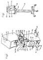
- FIG. 2The same device in FIG. 1, showing the individual components
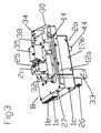
- FIG. 3The block feature of the invention as central part of FIG. 2 and
- FIG. 4The functionality and design of the preferred sample design can be seen in the block diagram in FIG. 4 : on the input side you will see the gas connections— 1 c compressor input, 1 a compressed air input, 1 b ventilation gas input, e.g. oxygen input and 27 therapy gas input, e.g. for NO.
- the inputsare sighted on a block 12 , which is found within the housing 7 .
- Comprising compressor input 1 cleads to a compressor 6 , which is connected via a flexible pipe 10 with a rigid pipe 11 a , which forms a compressed air pipe 4 to a gas supply container 8 .
- Pipe 11 ais interrupted by a valve 2 a , which either feeds or blocks the compressed air from the compressor or from the compressed air connection 1 a to the gas supply container 8 .
- a similar ventilation gas valve 2 bfeeds or blocks the ventilation gas passage to pipe 11 a from ventilation gas connection 1 b (in this case oxygen, for example).
- Pipe 11 cParallel to the pipe 11 a a rigid pipe 11 c , is fed through block 12 or is designed in the block wall in particular. Pipe 11 c connects the therapy gas connection 27 to the therapy gas output 28 . Pipe 11 c is divided by a controllable therapy gas valve 25 .
- This designwas preferable to the known superstructures, where the therapy gas pipes and therapy gas control valves were housed separately to the ventilator and therefore needed additional expenditure on equipment.
- the advantages over the known designinclude not only a reduced amount of housing and reduced structural volume, but it is also simpler to operate and clearer in use.
- the gas supply container 8is equipped with an oxygen sensor 26 . On the output side it is connected to the ventilator tube 5 via a rigid pipe 11 b .
- the rigid pipe 11 bhas a controllable inspiration valve 2 c .
- the pressure and/or flowis measured before as well as after the gas supply container 8 via integrated sensors 22 a and 22 b .
- a proximal flow sensor 23permits measurement of the patient's own breathing performance.
- the blockis divided into two—a lower section 12 b and an upper section 12 a .
- Thisis for assembly reasons and not essential.
- single piece or multi-piece blockscould be used for the invention.
- the lower section 12 bincludes an oxygen block 33 with oxygen sensor 26 and expiration valve 2 d .
- the lower section 12 bis screwed tightly to the upper section 12 a to form the gas supply container 8 on the inside.
- the shell walls of the upper and lower sections 12 a and 12 bcontain rigid pipes which represent the gas routes according to the block diagram in FIG. 4 .
- the gas supply pipesare at least 100 mm in length.
- a special pipeis represented by a broken line: gas deliverer 14 is a pipe which is connected to the compressor output 13 . Compressed air leaving the compressor is warm when it is expelled. As this warm air has to travel a relatively long way through gas deliverer 14 , this heat is released to block 12 . This reduces the risk of condensation building up in the gas supply container 8 .
- An alternative to the gas deliverer 14 shown herewould be to use a longer, perhaps spirally rolled pipe inside the gas supply container 8 to access the compressor output 13 .
- the upper section 12 aincludes the compressed air and ventilator gas connections 1 a and 1 b , as well as therapy gas connection 27 . It also carries a tank pressure control valve 32 , the inspiration valve 2 c , the therapy gas valve 25 , and a safety block 35 , which has a patient pressure relief valve and a patient suction relief valve. The last valves mentioned are equally located on valve block 38 , which is designed as an integrated block and which incorporates the emergency valves and the devices for flow and pressure measurement in particular.
- the upper section 12 aadditionally carries a nebulizer valve 34 and the front connections 30 .
- FIG. 2primarily shows the design in FIG. 3 when it is installed in housing 7 , which is illustrated in two sections ( 7 a , 7 b ) in this sample design.
- the compressor 6 with its flexible pipe 10is symbolically illustrated.
- the housing 7 byou can see a compartment with integrated battery 9 , the electronics 3 and the location of the DC connection 16 , an AC connection 39 , as well as an interface 21 for a wide variety of connections, such as RS232, nurse call, etc.
- the grips on the side 40are used for transportation, as is the stand 31 , which is shown in FIG. 1 .
Landscapes
- Health & Medical Sciences (AREA)
- Emergency Medicine (AREA)
- Pulmonology (AREA)
- Engineering & Computer Science (AREA)
- Anesthesiology (AREA)
- Biomedical Technology (AREA)
- Heart & Thoracic Surgery (AREA)
- Hematology (AREA)
- Life Sciences & Earth Sciences (AREA)
- Animal Behavior & Ethology (AREA)
- General Health & Medical Sciences (AREA)
- Public Health (AREA)
- Veterinary Medicine (AREA)
- Respiratory Apparatuses And Protective Means (AREA)
- Percussion Or Vibration Massage (AREA)
- External Artificial Organs (AREA)
- Orthopedics, Nursing, And Contraception (AREA)
- Duct Arrangements (AREA)
Abstract
Description
Claims (30)
Priority Applications (1)
| Application Number | Priority Date | Filing Date | Title |
|---|---|---|---|
| US10/893,421US7219666B2 (en) | 1999-04-07 | 2004-07-15 | Ventilator |
Applications Claiming Priority (3)
| Application Number | Priority Date | Filing Date | Title |
|---|---|---|---|
| CH65299 | 1999-04-07 | ||
| CH652/99 | 1999-04-07 | ||
| PCT/IB2000/000407WO2000059566A1 (en) | 1999-04-07 | 2000-04-03 | Breathing apparatus |
Related Child Applications (1)
| Application Number | Title | Priority Date | Filing Date |
|---|---|---|---|
| US10/893,421ContinuationUS7219666B2 (en) | 1999-04-07 | 2004-07-15 | Ventilator |
Publications (1)
| Publication Number | Publication Date |
|---|---|
| US6782888B1true US6782888B1 (en) | 2004-08-31 |
Family
ID=4192011
Family Applications (2)
| Application Number | Title | Priority Date | Filing Date |
|---|---|---|---|
| US09/958,520Expired - LifetimeUS6782888B1 (en) | 1999-04-07 | 2000-04-03 | Breathing apparatus |
| US10/893,421Expired - Fee RelatedUS7219666B2 (en) | 1999-04-07 | 2004-07-15 | Ventilator |
Family Applications After (1)
| Application Number | Title | Priority Date | Filing Date |
|---|---|---|---|
| US10/893,421Expired - Fee RelatedUS7219666B2 (en) | 1999-04-07 | 2004-07-15 | Ventilator |
Country Status (7)
| Country | Link |
|---|---|
| US (2) | US6782888B1 (en) |
| EP (1) | EP1171182B1 (en) |
| JP (1) | JP4212244B2 (en) |
| AT (1) | ATE414552T1 (en) |
| AU (1) | AU3448900A (en) |
| DE (1) | DE50015462D1 (en) |
| WO (1) | WO2000059566A1 (en) |
Cited By (52)
| Publication number | Priority date | Publication date | Assignee | Title |
|---|---|---|---|---|
| US20050000519A1 (en)* | 1999-04-07 | 2005-01-06 | Harri Friberg | Ventilator |
| WO2006058354A1 (en)* | 2004-12-01 | 2006-06-08 | Carl Reiner Gmbh | Method for providing gas mixtures for respirators and method for carrying out said method |
| US20070034208A1 (en)* | 2005-08-10 | 2007-02-15 | Roehl Robin L | Modular nitric oxide delivery device |
| US20070101993A1 (en)* | 2005-11-09 | 2007-05-10 | Bruce Dammann | System and method of integrating anesthesia agent monitoring in a respiratory carestation |
| US20080000474A1 (en)* | 2004-10-26 | 2008-01-03 | Map Medizin-Technologie Gmbh | Apparatus for Administering a Breathable Gas, and Components Thereof |
| US20080072902A1 (en)* | 2006-09-27 | 2008-03-27 | Nellcor Puritan Bennett Incorporated | Preset breath delivery therapies for a breathing assistance system |
| US7497215B1 (en)* | 2002-12-20 | 2009-03-03 | Koninklijke Philips Electronics N.V. | Medical ventilator with compressor heated exhalation filter |
| US20090062673A1 (en)* | 2007-08-29 | 2009-03-05 | Dave Scampoli | Electro-Pneumatic Assembly for Use in a Respiratory Measurement System |
| US7527053B2 (en) | 2003-08-04 | 2009-05-05 | Cardinal Health 203, Inc. | Method and apparatus for attenuating compressor noise |
| US7607437B2 (en) | 2003-08-04 | 2009-10-27 | Cardinal Health 203, Inc. | Compressor control system and method for a portable ventilator |
| USD638852S1 (en) | 2009-12-04 | 2011-05-31 | Nellcor Puritan Bennett Llc | Ventilator display screen with an alarm icon |
| US20110132369A1 (en)* | 2009-12-04 | 2011-06-09 | Nellcor Puritan Bennett Llc | Ventilation System With System Status Display |
| US20110132366A1 (en)* | 2009-12-03 | 2011-06-09 | Nellcor Puritan Bennett Llc | Ventilator Respiratory Gas Accumulator With Purge Valve |
| US7997885B2 (en) | 2007-12-03 | 2011-08-16 | Carefusion 303, Inc. | Roots-type blower reduced acoustic signature method and apparatus |
| US8001967B2 (en) | 1997-03-14 | 2011-08-23 | Nellcor Puritan Bennett Llc | Ventilator breath display and graphic user interface |
| US20110219091A1 (en)* | 2010-01-19 | 2011-09-08 | Event Medical, Inc. | System and method for communicating over a network with a medical device |
| USD645158S1 (en) | 2010-04-27 | 2011-09-13 | Nellcor Purtian Bennett LLC | System status display |
| US8021310B2 (en) | 2006-04-21 | 2011-09-20 | Nellcor Puritan Bennett Llc | Work of breathing display for a ventilation system |
| USD649157S1 (en) | 2009-12-04 | 2011-11-22 | Nellcor Puritan Bennett Llc | Ventilator display screen with a user interface |
| US8082312B2 (en) | 2008-12-12 | 2011-12-20 | Event Medical, Inc. | System and method for communicating over a network with a medical device |
| US8118024B2 (en) | 2003-08-04 | 2012-02-21 | Carefusion 203, Inc. | Mechanical ventilation system utilizing bias valve |
| US8156937B2 (en) | 2003-08-04 | 2012-04-17 | Carefusion 203, Inc. | Portable ventilator system |
| US8297279B2 (en) | 2003-08-04 | 2012-10-30 | Carefusion 203, Inc. | Portable ventilator system |
| US8335992B2 (en) | 2009-12-04 | 2012-12-18 | Nellcor Puritan Bennett Llc | Visual indication of settings changes on a ventilator graphical user interface |
| US8443294B2 (en) | 2009-12-18 | 2013-05-14 | Covidien Lp | Visual indication of alarms on a ventilator graphical user interface |
| US8453645B2 (en) | 2006-09-26 | 2013-06-04 | Covidien Lp | Three-dimensional waveform display for a breathing assistance system |
| US8453643B2 (en) | 2010-04-27 | 2013-06-04 | Covidien Lp | Ventilation system with system status display for configuration and program information |
| US8511306B2 (en) | 2010-04-27 | 2013-08-20 | Covidien Lp | Ventilation system with system status display for maintenance and service information |
| US8539949B2 (en) | 2010-04-27 | 2013-09-24 | Covidien Lp | Ventilation system with a two-point perspective view |
| US8844526B2 (en) | 2012-03-30 | 2014-09-30 | Covidien Lp | Methods and systems for triggering with unknown base flow |
| US8888711B2 (en) | 2008-04-08 | 2014-11-18 | Carefusion 203, Inc. | Flow sensor |
| US8924878B2 (en) | 2009-12-04 | 2014-12-30 | Covidien Lp | Display and access to settings on a ventilator graphical user interface |
| US8950398B2 (en) | 2008-09-30 | 2015-02-10 | Covidien Lp | Supplemental gas safety system for a breathing assistance system |
| US9084865B2 (en) | 2004-09-15 | 2015-07-21 | Covidien Ag | System and method for regulating a heating humidifier |
| US9119925B2 (en) | 2009-12-04 | 2015-09-01 | Covidien Lp | Quick initiation of respiratory support via a ventilator user interface |
| US9262588B2 (en) | 2009-12-18 | 2016-02-16 | Covidien Lp | Display of respiratory data graphs on a ventilator graphical user interface |
| US9492629B2 (en) | 2013-02-14 | 2016-11-15 | Covidien Lp | Methods and systems for ventilation with unknown exhalation flow and exhalation pressure |
| USD775345S1 (en) | 2015-04-10 | 2016-12-27 | Covidien Lp | Ventilator console |
| US9649458B2 (en) | 2008-09-30 | 2017-05-16 | Covidien Lp | Breathing assistance system with multiple pressure sensors |
| US9925346B2 (en) | 2015-01-20 | 2018-03-27 | Covidien Lp | Systems and methods for ventilation with unknown exhalation flow |
| US9950129B2 (en) | 2014-10-27 | 2018-04-24 | Covidien Lp | Ventilation triggering using change-point detection |
| US9956371B2 (en) | 2015-03-24 | 2018-05-01 | Ventec Life Systems, Inc. | Ventilator with integrated cough-assist |
| US9981096B2 (en) | 2013-03-13 | 2018-05-29 | Covidien Lp | Methods and systems for triggering with unknown inspiratory flow |
| US10362967B2 (en) | 2012-07-09 | 2019-07-30 | Covidien Lp | Systems and methods for missed breath detection and indication |
| US10773049B2 (en) | 2016-06-21 | 2020-09-15 | Ventec Life Systems, Inc. | Cough-assist systems with humidifier bypass |
| US11191915B2 (en) | 2018-05-13 | 2021-12-07 | Ventec Life Systems, Inc. | Portable medical ventilator system using portable oxygen concentrators |
| US11247015B2 (en) | 2015-03-24 | 2022-02-15 | Ventec Life Systems, Inc. | Ventilator with integrated oxygen production |
| US11672934B2 (en) | 2020-05-12 | 2023-06-13 | Covidien Lp | Remote ventilator adjustment |
| US11872349B2 (en) | 2020-04-10 | 2024-01-16 | Covidien Lp | Systems and methods for increasing ventilator oxygen concentration |
| US11883604B2 (en) | 2020-04-10 | 2024-01-30 | Covidien Lp | Gas mixing system for medical ventilator |
| DE102023123561A1 (en)* | 2023-09-01 | 2025-03-06 | Drägerwerk AG & Co. KGaA | Device and method for providing a respiratory gas flow |
| US12440634B2 (en) | 2021-12-21 | 2025-10-14 | Ventec Life Systems, Inc. | Ventilator systems with integrated oxygen delivery, and associated devices and methods |
Families Citing this family (19)
| Publication number | Priority date | Publication date | Assignee | Title |
|---|---|---|---|---|
| US7040318B2 (en) | 2001-07-30 | 2006-05-09 | Imt Medical Ag | Ventilator |
| JP4520702B2 (en)* | 2003-03-31 | 2010-08-11 | 帝人株式会社 | Battery arrangement method for battery-driven portable breathing gas supply device |
| US7464710B2 (en) | 2005-06-08 | 2008-12-16 | Norgren, Inc. | Manifold assembly for a ventilator system |
| US20060278230A1 (en)* | 2005-06-08 | 2006-12-14 | Imi Norgren, Inc. | Integrated manifold for a ventilator system |
| WO2007011678A1 (en)* | 2005-07-14 | 2007-01-25 | Norgren, Inc. | An integrated manifold for an oxygen supply system |
| US8153180B2 (en)* | 2005-09-06 | 2012-04-10 | Pepsico, Inc. | Method and apparatus for making beverages |
| US7509957B2 (en)* | 2006-02-21 | 2009-03-31 | Viasys Manufacturing, Inc. | Hardware configuration for pressure driver |
| JP5149025B2 (en)* | 2008-01-31 | 2013-02-20 | テルモ株式会社 | Oxygen concentrator |
| US20090205661A1 (en)* | 2008-02-20 | 2009-08-20 | Nellcor Puritan Bennett Llc | Systems and methods for extended volume range ventilation |
| US20100059059A1 (en)* | 2008-09-09 | 2010-03-11 | Perry Baromedical Corporation | Hyperbaric chamber |
| JP5517332B2 (en)* | 2009-08-28 | 2014-06-11 | アルバック機工株式会社 | Ventilator and its operating method |
| WO2011060204A2 (en)* | 2009-11-11 | 2011-05-19 | The Board Of Trustees Of The Leland Stanford Jr. University | Ventilation systems and methods |
| US8776792B2 (en) | 2011-04-29 | 2014-07-15 | Covidien Lp | Methods and systems for volume-targeted minimum pressure-control ventilation |
| US9289573B2 (en) | 2012-12-28 | 2016-03-22 | Covidien Lp | Ventilator pressure oscillation filter |
| JP6253029B2 (en)* | 2015-01-21 | 2017-12-27 | 大陽日酸株式会社 | Anesthesia mounting kit |
| WO2016128280A1 (en) | 2015-02-13 | 2016-08-18 | Koninklijke Philips N.V. | Portable medical support system with ancillary viewing mode and method of operation thereof |
| EP4186548A1 (en) | 2015-04-02 | 2023-05-31 | Hill-Rom Services PTE. LTD. | Mask leakage detection for a respiratory device |
| KR102778714B1 (en)* | 2018-10-30 | 2025-03-10 | 치에시 파마슈티시 에스.피.아. | A device for administering drugs to a patient on mechanical ventilation |
| ES1259300Y (en)* | 2020-03-29 | 2021-04-09 | Proton New Energy Future S L | INTELLIGENT DISTRIBUTION MODULE FOR RESPIRATORS |
Citations (9)
| Publication number | Priority date | Publication date | Assignee | Title |
|---|---|---|---|---|
| US4794922A (en)* | 1986-11-04 | 1989-01-03 | Bird Products Corporation | Ventilator manifold |
| US4870961A (en)* | 1986-09-22 | 1989-10-03 | Barnard Gordon D | Medical ventilator tube and manifold assembly |
| US4905688A (en)* | 1989-02-16 | 1990-03-06 | Figgie International Inc. | Portable light weight completely self-contained emergency single patient ventilator/resuscitator |
| US5549105A (en)* | 1993-09-09 | 1996-08-27 | L'air Liquide, Societe Anonyme Pour L'etude Et L'exploitation Des Procedes Georges Claude | Subassembly of network of gas conduits and anesthetic apparatus comprising such a subassembly |
| US5676133A (en)* | 1995-06-14 | 1997-10-14 | Apotheus Laboratories, Inc. | Expiratory scavenging method and apparatus and oxygen control system for post anesthesia care patients |
| US5694926A (en)* | 1994-10-14 | 1997-12-09 | Bird Products Corporation | Portable drag compressor powered mechanical ventilator |
| US6536430B1 (en)* | 1996-09-19 | 2003-03-25 | Charles A. Smith | Portable anesthesia rebreathing system |
| US6543449B1 (en)* | 1997-09-19 | 2003-04-08 | Respironics, Inc. | Medical ventilator |
| US6571792B1 (en)* | 1997-10-15 | 2003-06-03 | Datex-Ohmeda, Inc. | Smart modular anesthesia respiratory system |
Family Cites Families (74)
| Publication number | Priority date | Publication date | Assignee | Title |
|---|---|---|---|---|
| US4054133A (en)* | 1976-03-29 | 1977-10-18 | The Bendix Corporation | Control for a demand cannula |
| DE3109658C2 (en) | 1981-03-13 | 1984-04-05 | Drägerwerk AG, 2400 Lübeck | Electrically controllable breathing apparatus based on the circulatory principle |
| GB8305117D0 (en) | 1983-02-24 | 1983-03-30 | Penlon Ltd | Gas mixing and flow smoothing apparatus |
| DE3336578A1 (en)* | 1983-10-07 | 1985-04-18 | Siemens AG, 1000 Berlin und 8000 München | Arrangement for the connection of different lines |
| JPS60195049U (en) | 1984-06-04 | 1985-12-26 | 伊藤精機株式会社 | circulatory respiratory system |
| US4614162A (en)* | 1984-06-07 | 1986-09-30 | Frito-Lay, Inc. | Apparatus and method for distribution of seasonings and like granular/powdered materials |
| US4543907A (en)* | 1984-06-22 | 1985-10-01 | Frito-Lay, Inc. | Apparatus for seasoning snack food items |
| CH664056A5 (en)* | 1984-11-02 | 1988-01-29 | Borer Communications Ag | METHOD AND DEVICE FOR CONVERTING A DIGITAL DATA SEQUENCE IN THE ENCRYPTED FORM. |
| DE3523948A1 (en) | 1985-07-04 | 1987-01-08 | Draegerwerk Ag | DEVICE FOR SUPPLYING NARCOSIS DELIVERY DEVICES |
| US4702241A (en) | 1985-10-11 | 1987-10-27 | University Of Florida | Self-contained jet pump breathing apparatus |
| SE8700977D0 (en) | 1987-03-09 | 1987-03-09 | Olof Werner | UNIT WHICH SEPARATELY SEPARATES THE GAS CONTENT IN THE DRIVE CIRCUIT AND THE RECEIVER CIRCUIT BUT ONLY ALLOWS GAS PIPE IN THE BAD DIRECTIONS (OPEN SEPARATION) |
| US5322057A (en) | 1987-07-08 | 1994-06-21 | Vortran Medical Technology, Inc. | Intermittent signal actuated nebulizer synchronized to operate in the exhalation phase, and its method of use |
| US4883051A (en) | 1988-02-18 | 1989-11-28 | Summa Vest, Inc. | Disposable breathing system and components |
| US4986268A (en) | 1988-04-06 | 1991-01-22 | Tehrani Fleur T | Method and apparatus for controlling an artificial respirator |
| US4991576A (en) | 1988-10-11 | 1991-02-12 | Henkin Melvyn Lane | Anesthesia rebreathing system |
| US4881541A (en) | 1988-12-21 | 1989-11-21 | The Regents Of The University Of California | Vaporizer for an anesthetic having a vapor pressure about one atmosphere |
| DE3900276A1 (en) | 1989-01-07 | 1990-07-12 | Draegerwerk Ag | VENTILATOR WITH BREATHING CIRCUIT AND CONTROLLED FRESH GAS SUPPLY |
| US5325861A (en) | 1989-04-12 | 1994-07-05 | Puritan-Bennett Corporation | Method and apparatus for measuring a parameter of a gas in isolation from gas pressure fluctuations |
| GB8913085D0 (en) | 1989-06-07 | 1989-07-26 | Whitwam James G | Improvements in or relating to medical ventilators |
| US5090593A (en)* | 1990-04-18 | 1992-02-25 | Recot, Inc. | Apparatus and method for distributing seasoning |
| US6400996B1 (en) | 1999-02-01 | 2002-06-04 | Steven M. Hoffberg | Adaptive pattern recognition based control system and method |
| DE59305405D1 (en) | 1992-04-16 | 1997-03-20 | Obermayer Anton | ANESTHESIA MACHINE |
| US5368019A (en) | 1992-12-16 | 1994-11-29 | Puritan-Bennett Corporation | System and method for operating a respirator compressor system under low voltage conditions |
| US5570682A (en) | 1993-12-14 | 1996-11-05 | Ethex International, Inc. | Passive inspiratory nebulizer system |
| DE19500529C5 (en) | 1995-01-11 | 2007-11-22 | Dräger Medical AG & Co. KG | Control unit for a ventilator |
| FI104411B (en) | 1995-01-23 | 2000-01-31 | Instrumentarium Oy | Arrangement in connection with anesthetic vaporization |
| EP0792177B1 (en) | 1995-02-08 | 2002-05-22 | Puritan-Bennett Corporation | Gas mixing apparatus for a ventilator |
| SE9601065L (en) | 1996-03-20 | 1997-03-03 | Siemens Elema Ab | Anesthesia System |
| US5598838A (en) | 1995-04-07 | 1997-02-04 | Healthdyne Technologies, Inc. | Pressure support ventilatory assist system |
| SE9503665L (en) | 1995-10-19 | 1997-04-20 | Siemens Elema Ab | Anesthesia System |
| US6041777A (en) | 1995-12-01 | 2000-03-28 | Alliance Pharmaceutical Corp. | Methods and apparatus for closed-circuit ventilation therapy |
| SE9504580L (en) | 1995-12-21 | 1997-06-22 | Siemens Elema Ab | Procedure for gasification of an anesthetic fluid and a carburetor |
| US5887611A (en) | 1996-12-31 | 1999-03-30 | The University Of Florida | Gas blender |
| US5846324A (en)* | 1997-02-14 | 1998-12-08 | Fmc Corporation | Seasoning spreader |
| US6021777A (en) | 1997-03-13 | 2000-02-08 | Anesta-Pac, Inc. | Portable anesthesia machine |
| DE19711595C2 (en) | 1997-03-20 | 2003-06-12 | Draegerwerk Ag | Method for controlling a valve in a ventilator |
| ES2242289T3 (en) | 1997-07-25 | 2005-11-01 | MINNESOTA INNOVATIVE TECHNOLOGIES & INSTRUMENTS CORPORATION (MITI) | CONTROL DEVICE TO SUPPLY SUPPLEMENTARY OXYGEN FOR BREATHING. |
| US6213120B1 (en) | 1997-08-21 | 2001-04-10 | Instrumentarium Corporation | Device and method for determining gas volume and volumetric changes in a ventilator |
| SE508440C2 (en)* | 1997-09-11 | 1998-10-05 | Siemens Elema Ab | inspiration Hose |
| US6216690B1 (en) | 1997-10-15 | 2001-04-17 | Datex-Ohmeda, Inc. | Method and apparatus for rapid control of set inspired gas concentration in anesthesia delivery systems |
| NL1007699C2 (en) | 1997-12-04 | 1999-06-09 | Medisize Bv | Ventilation system. |
| ATE303837T1 (en) | 1998-03-05 | 2005-09-15 | Zivena Inc | LUNG DOSING SYSTEM |
| US6089229A (en) | 1998-05-26 | 2000-07-18 | Datex-Ohmeda, Inc. | High concentration no pulse delivery device |
| US20030062045A1 (en) | 1998-09-18 | 2003-04-03 | Respironics, Inc. | Medical ventilator |
| US6279574B1 (en) | 1998-12-04 | 2001-08-28 | Bunnell, Incorporated | Variable flow and pressure ventilation system |
| SE9900368D0 (en) | 1999-02-04 | 1999-02-04 | Siemens Elema Ab | Anesthesia apparatus |
| DE50015462D1 (en)* | 1999-04-07 | 2009-01-02 | Event Medical Ltd | VENTILATOR |
| EP1223855B1 (en) | 1999-10-01 | 2006-08-30 | Glaxo Group Limited | Medicament delivery system |
| US6837260B1 (en) | 1999-11-02 | 2005-01-04 | Respironics, Inc. | Pressure support system having a two-piece assembly |
| AUPQ466999A0 (en) | 1999-12-15 | 2000-01-13 | Dunlop, Colin | Anaesthetic apparatus |
| US6948494B1 (en) | 2000-05-10 | 2005-09-27 | Innovative Devices, Llc. | Medicament container with same side airflow inlet and outlet and method of use |
| US6588363B1 (en)* | 2000-08-17 | 2003-07-08 | Paul J. Svejkovsky | Seasoning system and method |
| US20020022072A1 (en)* | 2000-08-17 | 2002-02-21 | Burke David L. | Seasoning system and method |
| US6553931B2 (en)* | 2001-02-20 | 2003-04-29 | Recot, Inc. | Vibrating funnel fingers for distribution of seasoning onto discrete lanes |
| SE0100757D0 (en) | 2001-03-07 | 2001-03-07 | Siemens Elema Ab | Exspirationskassett |
| US7040318B2 (en) | 2001-07-30 | 2006-05-09 | Imt Medical Ag | Ventilator |
| DE10205845C1 (en) | 2002-02-13 | 2002-10-31 | Draeger Medical Ag | Mixing device used in portable breathing apparatus comprises ejectors, central suction channel, valves for regulating feed via propellant gas connections, volume stream sensors, and evaluating and control unit |
| US6644237B2 (en)* | 2002-02-19 | 2003-11-11 | Recot, Inc. | Variable geometry seasoning tumbler |
| US6619226B2 (en)* | 2002-02-19 | 2003-09-16 | Recot, Inc. | Sifter seasoning applicator |
| US6705316B2 (en) | 2002-03-11 | 2004-03-16 | Battelle Pulmonary Therapeutics, Inc. | Pulmonary dosing system and method |
| US20040172301A1 (en) | 2002-04-30 | 2004-09-02 | Mihai Dan M. | Remote multi-purpose user interface for a healthcare system |
| US20050055242A1 (en) | 2002-04-30 | 2005-03-10 | Bryan Bello | System and method for medical data tracking, analysis and reporting for healthcare system |
| GB0211906D0 (en) | 2002-05-23 | 2002-07-03 | Boc Group Plc | Medical Apparatus |
| SE0203342D0 (en) | 2002-11-13 | 2002-11-13 | Siemens Elema Ab | Absorbent device for anesthesia |
| SE0203430D0 (en) | 2002-11-20 | 2002-11-20 | Siemens Elema Ab | Anesthesia apparatus |
| US7886740B2 (en) | 2003-01-28 | 2011-02-15 | Beth Israel Deaconess Medical Center, Inc. | Gas systems and methods for enabling respiratory stability |
| US20040250813A1 (en) | 2003-06-16 | 2004-12-16 | Post Terry Michael | Portable digital anesthesia apparatus |
| US20050055244A1 (en) | 2003-07-18 | 2005-03-10 | Janet Mullan | Wireless medical communication system and method |
| US8251061B2 (en) | 2003-09-18 | 2012-08-28 | Cardiac Pacemakers, Inc. | Methods and systems for control of gas therapy |
| US7967756B2 (en) | 2003-09-18 | 2011-06-28 | Cardiac Pacemakers, Inc. | Respiratory therapy control based on cardiac cycle |
| US7970470B2 (en) | 2003-09-18 | 2011-06-28 | Cardiac Pacemakers, Inc. | Diagnosis and/or therapy using blood chemistry/expired gas parameter analysis |
| US7802571B2 (en) | 2003-11-21 | 2010-09-28 | Tehrani Fleur T | Method and apparatus for controlling a ventilator |
| US7607435B2 (en) | 2004-01-21 | 2009-10-27 | Battelle Memorial Institute | Gas or liquid flow sensor |
| US7290541B2 (en) | 2004-04-20 | 2007-11-06 | Aerogen, Inc. | Aerosol delivery apparatus and method for pressure-assisted breathing systems |
- 2000
- 2000-04-03DEDE50015462Tpatent/DE50015462D1/ennot_activeExpired - Lifetime
- 2000-04-03AUAU34489/00Apatent/AU3448900A/ennot_activeAbandoned
- 2000-04-03USUS09/958,520patent/US6782888B1/ennot_activeExpired - Lifetime
- 2000-04-03JPJP2000609125Apatent/JP4212244B2/ennot_activeExpired - Fee Related
- 2000-04-03EPEP00912848Apatent/EP1171182B1/ennot_activeExpired - Lifetime
- 2000-04-03WOPCT/IB2000/000407patent/WO2000059566A1/enactiveApplication Filing
- 2000-04-03ATAT00912848Tpatent/ATE414552T1/ennot_activeIP Right Cessation
- 2004
- 2004-07-15USUS10/893,421patent/US7219666B2/ennot_activeExpired - Fee Related
Patent Citations (9)
| Publication number | Priority date | Publication date | Assignee | Title |
|---|---|---|---|---|
| US4870961A (en)* | 1986-09-22 | 1989-10-03 | Barnard Gordon D | Medical ventilator tube and manifold assembly |
| US4794922A (en)* | 1986-11-04 | 1989-01-03 | Bird Products Corporation | Ventilator manifold |
| US4905688A (en)* | 1989-02-16 | 1990-03-06 | Figgie International Inc. | Portable light weight completely self-contained emergency single patient ventilator/resuscitator |
| US5549105A (en)* | 1993-09-09 | 1996-08-27 | L'air Liquide, Societe Anonyme Pour L'etude Et L'exploitation Des Procedes Georges Claude | Subassembly of network of gas conduits and anesthetic apparatus comprising such a subassembly |
| US5694926A (en)* | 1994-10-14 | 1997-12-09 | Bird Products Corporation | Portable drag compressor powered mechanical ventilator |
| US5676133A (en)* | 1995-06-14 | 1997-10-14 | Apotheus Laboratories, Inc. | Expiratory scavenging method and apparatus and oxygen control system for post anesthesia care patients |
| US6536430B1 (en)* | 1996-09-19 | 2003-03-25 | Charles A. Smith | Portable anesthesia rebreathing system |
| US6543449B1 (en)* | 1997-09-19 | 2003-04-08 | Respironics, Inc. | Medical ventilator |
| US6571792B1 (en)* | 1997-10-15 | 2003-06-03 | Datex-Ohmeda, Inc. | Smart modular anesthesia respiratory system |
Cited By (103)
| Publication number | Priority date | Publication date | Assignee | Title |
|---|---|---|---|---|
| US8555881B2 (en) | 1997-03-14 | 2013-10-15 | Covidien Lp | Ventilator breath display and graphic interface |
| US8555882B2 (en) | 1997-03-14 | 2013-10-15 | Covidien Lp | Ventilator breath display and graphic user interface |
| US8001967B2 (en) | 1997-03-14 | 2011-08-23 | Nellcor Puritan Bennett Llc | Ventilator breath display and graphic user interface |
| US20050000519A1 (en)* | 1999-04-07 | 2005-01-06 | Harri Friberg | Ventilator |
| US7219666B2 (en)* | 1999-04-07 | 2007-05-22 | Event Medical Limited | Ventilator |
| US7497215B1 (en)* | 2002-12-20 | 2009-03-03 | Koninklijke Philips Electronics N.V. | Medical ventilator with compressor heated exhalation filter |
| US7926485B2 (en) | 2002-12-20 | 2011-04-19 | Ric Investments, Llc | Medical ventilator with compressor heated exhalation filter |
| US20090071479A1 (en)* | 2002-12-20 | 2009-03-19 | Ric Investments Llc | Medical ventilator with compressor heated exhalation filter |
| US8677995B2 (en) | 2003-08-04 | 2014-03-25 | Carefusion 203, Inc. | Compressor control system for a portable ventilator |
| US8683997B2 (en) | 2003-08-04 | 2014-04-01 | Carefusion 203, Inc. | Portable ventilator system |
| US8156937B2 (en) | 2003-08-04 | 2012-04-17 | Carefusion 203, Inc. | Portable ventilator system |
| US8627819B2 (en) | 2003-08-04 | 2014-01-14 | Carefusion 203, Inc. | Portable ventilator system |
| US7527053B2 (en) | 2003-08-04 | 2009-05-05 | Cardinal Health 203, Inc. | Method and apparatus for attenuating compressor noise |
| US7607437B2 (en) | 2003-08-04 | 2009-10-27 | Cardinal Health 203, Inc. | Compressor control system and method for a portable ventilator |
| US10118011B2 (en) | 2003-08-04 | 2018-11-06 | Carefusion 203, Inc. | Mechanical ventilation system utilizing bias valve |
| US8522780B2 (en) | 2003-08-04 | 2013-09-03 | Carefusion 203, Inc. | Portable ventilator system |
| US8297279B2 (en) | 2003-08-04 | 2012-10-30 | Carefusion 203, Inc. | Portable ventilator system |
| US8118024B2 (en) | 2003-08-04 | 2012-02-21 | Carefusion 203, Inc. | Mechanical ventilation system utilizing bias valve |
| US9084865B2 (en) | 2004-09-15 | 2015-07-21 | Covidien Ag | System and method for regulating a heating humidifier |
| US20080000474A1 (en)* | 2004-10-26 | 2008-01-03 | Map Medizin-Technologie Gmbh | Apparatus for Administering a Breathable Gas, and Components Thereof |
| WO2006058354A1 (en)* | 2004-12-01 | 2006-06-08 | Carl Reiner Gmbh | Method for providing gas mixtures for respirators and method for carrying out said method |
| US20080127975A1 (en)* | 2004-12-01 | 2008-06-05 | Dominik Lirsch | Method for Preparing Gas Mixtures for Lung Ventilators and Device for Carrying Out this Method |
| US20070034208A1 (en)* | 2005-08-10 | 2007-02-15 | Roehl Robin L | Modular nitric oxide delivery device |
| US7455062B2 (en)* | 2005-08-10 | 2008-11-25 | The General Electric Company | Modular nitric oxide delivery device |
| US7987848B2 (en)* | 2005-11-09 | 2011-08-02 | General Electric Company | System and method of integrating anesthesia agent monitoring in a respiratory carestation |
| US20070101993A1 (en)* | 2005-11-09 | 2007-05-10 | Bruce Dammann | System and method of integrating anesthesia agent monitoring in a respiratory carestation |
| US10582880B2 (en) | 2006-04-21 | 2020-03-10 | Covidien Lp | Work of breathing display for a ventilation system |
| US8021310B2 (en) | 2006-04-21 | 2011-09-20 | Nellcor Puritan Bennett Llc | Work of breathing display for a ventilation system |
| US8597198B2 (en) | 2006-04-21 | 2013-12-03 | Covidien Lp | Work of breathing display for a ventilation system |
| US8453645B2 (en) | 2006-09-26 | 2013-06-04 | Covidien Lp | Three-dimensional waveform display for a breathing assistance system |
| US20080072902A1 (en)* | 2006-09-27 | 2008-03-27 | Nellcor Puritan Bennett Incorporated | Preset breath delivery therapies for a breathing assistance system |
| US20090062673A1 (en)* | 2007-08-29 | 2009-03-05 | Dave Scampoli | Electro-Pneumatic Assembly for Use in a Respiratory Measurement System |
| US7997885B2 (en) | 2007-12-03 | 2011-08-16 | Carefusion 303, Inc. | Roots-type blower reduced acoustic signature method and apparatus |
| US9375166B2 (en) | 2008-04-08 | 2016-06-28 | Carefusion 203, Inc. | Flow sensor |
| US9713438B2 (en) | 2008-04-08 | 2017-07-25 | Carefusion 203, Inc. | Flow sensor |
| US8888711B2 (en) | 2008-04-08 | 2014-11-18 | Carefusion 203, Inc. | Flow sensor |
| US9649458B2 (en) | 2008-09-30 | 2017-05-16 | Covidien Lp | Breathing assistance system with multiple pressure sensors |
| US8950398B2 (en) | 2008-09-30 | 2015-02-10 | Covidien Lp | Supplemental gas safety system for a breathing assistance system |
| US8082312B2 (en) | 2008-12-12 | 2011-12-20 | Event Medical, Inc. | System and method for communicating over a network with a medical device |
| US8434481B2 (en) | 2009-12-03 | 2013-05-07 | Covidien Lp | Ventilator respiratory gas accumulator with dip tube |
| US20110132366A1 (en)* | 2009-12-03 | 2011-06-09 | Nellcor Puritan Bennett Llc | Ventilator Respiratory Gas Accumulator With Purge Valve |
| US8434484B2 (en) | 2009-12-03 | 2013-05-07 | Covidien Lp | Ventilator Respiratory Variable-Sized Gas Accumulator |
| US8434483B2 (en) | 2009-12-03 | 2013-05-07 | Covidien Lp | Ventilator respiratory gas accumulator with sampling chamber |
| US8424523B2 (en) | 2009-12-03 | 2013-04-23 | Covidien Lp | Ventilator respiratory gas accumulator with purge valve |
| US9089665B2 (en) | 2009-12-03 | 2015-07-28 | Covidien Lp | Ventilator respiratory variable-sized gas accumulator |
| US8677996B2 (en) | 2009-12-04 | 2014-03-25 | Covidien Lp | Ventilation system with system status display including a user interface |
| US8418692B2 (en) | 2009-12-04 | 2013-04-16 | Covidien Lp | Ventilation system with removable primary display |
| US8335992B2 (en) | 2009-12-04 | 2012-12-18 | Nellcor Puritan Bennett Llc | Visual indication of settings changes on a ventilator graphical user interface |
| US8924878B2 (en) | 2009-12-04 | 2014-12-30 | Covidien Lp | Display and access to settings on a ventilator graphical user interface |
| US9119925B2 (en) | 2009-12-04 | 2015-09-01 | Covidien Lp | Quick initiation of respiratory support via a ventilator user interface |
| USD649157S1 (en) | 2009-12-04 | 2011-11-22 | Nellcor Puritan Bennett Llc | Ventilator display screen with a user interface |
| US20110132369A1 (en)* | 2009-12-04 | 2011-06-09 | Nellcor Puritan Bennett Llc | Ventilation System With System Status Display |
| USD638852S1 (en) | 2009-12-04 | 2011-05-31 | Nellcor Puritan Bennett Llc | Ventilator display screen with an alarm icon |
| US8499252B2 (en) | 2009-12-18 | 2013-07-30 | Covidien Lp | Display of respiratory data graphs on a ventilator graphical user interface |
| US9262588B2 (en) | 2009-12-18 | 2016-02-16 | Covidien Lp | Display of respiratory data graphs on a ventilator graphical user interface |
| US8443294B2 (en) | 2009-12-18 | 2013-05-14 | Covidien Lp | Visual indication of alarms on a ventilator graphical user interface |
| US20110231505A1 (en)* | 2010-01-19 | 2011-09-22 | Event Medical, Inc. | System and method for communicating over a network with a medical device |
| US20110219090A1 (en)* | 2010-01-19 | 2011-09-08 | Event Medical, Inc. | System and method for communicating over a network with a medical device |
| US20110219091A1 (en)* | 2010-01-19 | 2011-09-08 | Event Medical, Inc. | System and method for communicating over a network with a medical device |
| US8060576B2 (en) | 2010-01-19 | 2011-11-15 | Event Medical, Inc. | System and method for communicating over a network with a medical device |
| US8171094B2 (en) | 2010-01-19 | 2012-05-01 | Event Medical, Inc. | System and method for communicating over a network with a medical device |
| US8453643B2 (en) | 2010-04-27 | 2013-06-04 | Covidien Lp | Ventilation system with system status display for configuration and program information |
| USD656237S1 (en) | 2010-04-27 | 2012-03-20 | Nellcor Puritan Bennett Llc | Display screen on a system status display |
| US9387297B2 (en) | 2010-04-27 | 2016-07-12 | Covidien Lp | Ventilation system with a two-point perspective view |
| US8511306B2 (en) | 2010-04-27 | 2013-08-20 | Covidien Lp | Ventilation system with system status display for maintenance and service information |
| USD645158S1 (en) | 2010-04-27 | 2011-09-13 | Nellcor Purtian Bennett LLC | System status display |
| US8539949B2 (en) | 2010-04-27 | 2013-09-24 | Covidien Lp | Ventilation system with a two-point perspective view |
| US8844526B2 (en) | 2012-03-30 | 2014-09-30 | Covidien Lp | Methods and systems for triggering with unknown base flow |
| US10029057B2 (en) | 2012-03-30 | 2018-07-24 | Covidien Lp | Methods and systems for triggering with unknown base flow |
| US10362967B2 (en) | 2012-07-09 | 2019-07-30 | Covidien Lp | Systems and methods for missed breath detection and indication |
| US11642042B2 (en) | 2012-07-09 | 2023-05-09 | Covidien Lp | Systems and methods for missed breath detection and indication |
| US9492629B2 (en) | 2013-02-14 | 2016-11-15 | Covidien Lp | Methods and systems for ventilation with unknown exhalation flow and exhalation pressure |
| US9981096B2 (en) | 2013-03-13 | 2018-05-29 | Covidien Lp | Methods and systems for triggering with unknown inspiratory flow |
| US11712174B2 (en) | 2014-10-27 | 2023-08-01 | Covidien Lp | Ventilation triggering |
| US10940281B2 (en) | 2014-10-27 | 2021-03-09 | Covidien Lp | Ventilation triggering |
| US9950129B2 (en) | 2014-10-27 | 2018-04-24 | Covidien Lp | Ventilation triggering using change-point detection |
| US9925346B2 (en) | 2015-01-20 | 2018-03-27 | Covidien Lp | Systems and methods for ventilation with unknown exhalation flow |
| US10315002B2 (en) | 2015-03-24 | 2019-06-11 | Ventec Life Systems, Inc. | Ventilator with integrated oxygen production |
| US11344692B2 (en) | 2015-03-24 | 2022-05-31 | Ventec Life Systems, Inc. | Respiratory therapy systems and methods |
| US10518059B2 (en) | 2015-03-24 | 2019-12-31 | Ventec Life Systems, Inc. | Passive leak valve |
| US10576237B2 (en) | 2015-03-24 | 2020-03-03 | Ventec Life Systems, Inc. | Active exhalation valve |
| US10105509B2 (en) | 2015-03-24 | 2018-10-23 | Ventec Life Systems, Inc. | Active exhalation valve |
| US10758699B2 (en) | 2015-03-24 | 2020-09-01 | Ventec Life Systems, Inc. | Secretion trap |
| US11185655B2 (en) | 2015-03-24 | 2021-11-30 | Ventec Life Systems, Inc. | Passive leak valve |
| US9956371B2 (en) | 2015-03-24 | 2018-05-01 | Ventec Life Systems, Inc. | Ventilator with integrated cough-assist |
| US10245406B2 (en) | 2015-03-24 | 2019-04-02 | Ventec Life Systems, Inc. | Ventilator with integrated oxygen production |
| US11992619B2 (en) | 2015-03-24 | 2024-05-28 | Ventec Life Systems, Inc. | Ventilator with integrated cough-assist |
| US11247015B2 (en) | 2015-03-24 | 2022-02-15 | Ventec Life Systems, Inc. | Ventilator with integrated oxygen production |
| US11291791B2 (en) | 2015-03-24 | 2022-04-05 | Ventee Life Systems, Inc. | Ventilator with integrated cough-assist |
| US10046134B2 (en) | 2015-03-24 | 2018-08-14 | Ventec Life Systems, Inc. | Pressure swing adsorption oxygen generator |
| USD775345S1 (en) | 2015-04-10 | 2016-12-27 | Covidien Lp | Ventilator console |
| US10773049B2 (en) | 2016-06-21 | 2020-09-15 | Ventec Life Systems, Inc. | Cough-assist systems with humidifier bypass |
| US11679229B2 (en) | 2016-06-21 | 2023-06-20 | Ventec Life Systems, Inc. | Cough-assist systems with humidifier bypass |
| US12246135B2 (en) | 2016-06-21 | 2025-03-11 | Ventec Life Systems, Inc. | Cough-assist systems with humidifier bypass |
| US11191915B2 (en) | 2018-05-13 | 2021-12-07 | Ventec Life Systems, Inc. | Portable medical ventilator system using portable oxygen concentrators |
| US12370333B2 (en) | 2018-05-13 | 2025-07-29 | Ventec Life Systems, Inc. | Portable medical ventilator system using portable oxygen concentrators |
| US12434026B2 (en) | 2018-05-13 | 2025-10-07 | Ventec Life Systems, Inc. | Portable medical ventilator system using portable oxygen concentrators |
| US11872349B2 (en) | 2020-04-10 | 2024-01-16 | Covidien Lp | Systems and methods for increasing ventilator oxygen concentration |
| US11883604B2 (en) | 2020-04-10 | 2024-01-30 | Covidien Lp | Gas mixing system for medical ventilator |
| US11672934B2 (en) | 2020-05-12 | 2023-06-13 | Covidien Lp | Remote ventilator adjustment |
| US12144925B2 (en) | 2020-05-12 | 2024-11-19 | Covidien Lp | Remote ventilator adjustment |
| US12440634B2 (en) | 2021-12-21 | 2025-10-14 | Ventec Life Systems, Inc. | Ventilator systems with integrated oxygen delivery, and associated devices and methods |
| DE102023123561A1 (en)* | 2023-09-01 | 2025-03-06 | Drägerwerk AG & Co. KGaA | Device and method for providing a respiratory gas flow |
Also Published As
| Publication number | Publication date |
|---|---|
| US7219666B2 (en) | 2007-05-22 |
| JP4212244B2 (en) | 2009-01-21 |
| WO2000059566A1 (en) | 2000-10-12 |
| US20050000519A1 (en) | 2005-01-06 |
| JP2002540858A (en) | 2002-12-03 |
| DE50015462D1 (en) | 2009-01-02 |
| ATE414552T1 (en) | 2008-12-15 |
| AU3448900A (en) | 2000-10-23 |
| EP1171182B1 (en) | 2008-11-19 |
| EP1171182A1 (en) | 2002-01-16 |
Similar Documents
| Publication | Publication Date | Title |
|---|---|---|
| US6782888B1 (en) | Breathing apparatus | |
| US20230014248A1 (en) | Modular ventilation system | |
| US20190134325A1 (en) | Continuous positive airway pressure device with user interface | |
| US5237987A (en) | Human lung ventilator system | |
| US3990442A (en) | Respiratory treatment device | |
| US5287849A (en) | Medicinal aerosol delivery system and method of use | |
| US8667963B2 (en) | Ventilator circuit for oxygen generating system | |
| US20040244795A1 (en) | Ventilator | |
| CN113577477A (en) | Gas circuit system and breathing machine | |
| AU2021326637A1 (en) | Assisted breathing apparatus and method | |
| EP3756710B1 (en) | Icu-special portable atomizing device enabling autonomously breathing according to airflow | |
| US20160339202A1 (en) | Ventilators and ventilator systems | |
| US6095138A (en) | Portable respiration apparatus, and system employing same | |
| EP0519742A1 (en) | Medical nebulizer control system | |
| US20180110954A1 (en) | Ventilator apparaus and systems | |
| US6186143B1 (en) | Apparatus for supplying atmospheric air and at least one additional gas to a respirating subject | |
| CN213048868U (en) | Anesthetic atomizing device | |
| CN110812636A (en) | Portable atomization device for ICU autonomous respiration according to airflow | |
| CN216258620U (en) | Gas circuit system and breathing machine | |
| JP7609873B2 (en) | Portable ventilator with power supply through power grid and power storage device | |
| Fludger et al. | Portable ventilators | |
| US20240350755A1 (en) | Medical ventilator with ventilation modes adapted for cardiac massage | |
| CN222467762U (en) | A ventilator device | |
| RU2108084C1 (en) | Device for artificial pulmonary ventilation | |
| TR202010460A2 (en) | A VENTILATION DEVICE |
Legal Events
| Date | Code | Title | Description |
|---|---|---|---|
| AS | Assignment | Owner name:EVENT MEDICAL LIMITED, IRELAND Free format text:ASSIGNMENT OF ASSIGNORS INTEREST;ASSIGNORS:FRIBERG, HARRI;DASCHER, JAKOB;REEL/FRAME:012618/0473 Effective date:20011127 | |
| STCF | Information on status: patent grant | Free format text:PATENTED CASE | |
| FEPP | Fee payment procedure | Free format text:PAYOR NUMBER ASSIGNED (ORIGINAL EVENT CODE: ASPN); ENTITY STATUS OF PATENT OWNER: SMALL ENTITY | |
| FEPP | Fee payment procedure | Free format text:PAT HOLDER NO LONGER CLAIMS SMALL ENTITY STATUS, ENTITY STATUS SET TO UNDISCOUNTED (ORIGINAL EVENT CODE: STOL); ENTITY STATUS OF PATENT OWNER: SMALL ENTITY | |
| CC | Certificate of correction | ||
| FPAY | Fee payment | Year of fee payment:4 | |
| REMI | Maintenance fee reminder mailed | ||
| FEPP | Fee payment procedure | Free format text:PAYER NUMBER DE-ASSIGNED (ORIGINAL EVENT CODE: RMPN); ENTITY STATUS OF PATENT OWNER: SMALL ENTITY Free format text:PAYOR NUMBER ASSIGNED (ORIGINAL EVENT CODE: ASPN); ENTITY STATUS OF PATENT OWNER: SMALL ENTITY | |
| FEPP | Fee payment procedure | Free format text:PAT HOLDER CLAIMS SMALL ENTITY STATUS, ENTITY STATUS SET TO SMALL (ORIGINAL EVENT CODE: LTOS); ENTITY STATUS OF PATENT OWNER: SMALL ENTITY | |
| FPAY | Fee payment | Year of fee payment:8 | |
| FPAY | Fee payment | Year of fee payment:12 |