US6780179B2 - Methods and systems for in situ tissue marking and orientation stabilization - Google Patents
Methods and systems for in situ tissue marking and orientation stabilizationDownload PDFInfo
- Publication number
- US6780179B2 US6780179B2US10/155,570US15557002AUS6780179B2US 6780179 B2US6780179 B2US 6780179B2US 15557002 AUS15557002 AUS 15557002AUS 6780179 B2US6780179 B2US 6780179B2
- Authority
- US
- United States
- Prior art keywords
- tissue
- specimen
- marking
- tool
- dye
- Prior art date
- Legal status (The legal status is an assumption and is not a legal conclusion. Google has not performed a legal analysis and makes no representation as to the accuracy of the status listed.)
- Expired - Fee Related, expires
Links
Images


Classifications
- A—HUMAN NECESSITIES
- A61—MEDICAL OR VETERINARY SCIENCE; HYGIENE
- A61B—DIAGNOSIS; SURGERY; IDENTIFICATION
- A61B10/00—Instruments for taking body samples for diagnostic purposes; Other methods or instruments for diagnosis, e.g. for vaccination diagnosis, sex determination or ovulation-period determination; Throat striking implements
- A61B10/02—Instruments for taking cell samples or for biopsy
- A61B10/0233—Pointed or sharp biopsy instruments
- A61B10/0266—Pointed or sharp biopsy instruments means for severing sample
- A—HUMAN NECESSITIES
- A61—MEDICAL OR VETERINARY SCIENCE; HYGIENE
- A61B—DIAGNOSIS; SURGERY; IDENTIFICATION
- A61B18/00—Surgical instruments, devices or methods for transferring non-mechanical forms of energy to or from the body
- A61B18/04—Surgical instruments, devices or methods for transferring non-mechanical forms of energy to or from the body by heating
- A61B18/12—Surgical instruments, devices or methods for transferring non-mechanical forms of energy to or from the body by heating by passing a current through the tissue to be heated, e.g. high-frequency current
- A61B18/14—Probes or electrodes therefor
- A61B18/148—Probes or electrodes therefor having a short, rigid shaft for accessing the inner body transcutaneously, e.g. for neurosurgery or arthroscopy
- A—HUMAN NECESSITIES
- A61—MEDICAL OR VETERINARY SCIENCE; HYGIENE
- A61B—DIAGNOSIS; SURGERY; IDENTIFICATION
- A61B18/00—Surgical instruments, devices or methods for transferring non-mechanical forms of energy to or from the body
- A61B2018/00315—Surgical instruments, devices or methods for transferring non-mechanical forms of energy to or from the body for treatment of particular body parts
- A61B2018/00333—Breast
- A—HUMAN NECESSITIES
- A61—MEDICAL OR VETERINARY SCIENCE; HYGIENE
- A61B—DIAGNOSIS; SURGERY; IDENTIFICATION
- A61B18/00—Surgical instruments, devices or methods for transferring non-mechanical forms of energy to or from the body
- A61B2018/00571—Surgical instruments, devices or methods for transferring non-mechanical forms of energy to or from the body for achieving a particular surgical effect
- A61B2018/00601—Cutting
- A—HUMAN NECESSITIES
- A61—MEDICAL OR VETERINARY SCIENCE; HYGIENE
- A61B—DIAGNOSIS; SURGERY; IDENTIFICATION
- A61B18/00—Surgical instruments, devices or methods for transferring non-mechanical forms of energy to or from the body
- A61B18/04—Surgical instruments, devices or methods for transferring non-mechanical forms of energy to or from the body by heating
- A61B18/12—Surgical instruments, devices or methods for transferring non-mechanical forms of energy to or from the body by heating by passing a current through the tissue to be heated, e.g. high-frequency current
- A61B18/14—Probes or electrodes therefor
- A61B2018/1405—Electrodes having a specific shape
- A61B2018/1407—Loop
- A61B2018/141—Snare
- A—HUMAN NECESSITIES
- A61—MEDICAL OR VETERINARY SCIENCE; HYGIENE
- A61B—DIAGNOSIS; SURGERY; IDENTIFICATION
- A61B18/00—Surgical instruments, devices or methods for transferring non-mechanical forms of energy to or from the body
- A61B18/04—Surgical instruments, devices or methods for transferring non-mechanical forms of energy to or from the body by heating
- A61B18/12—Surgical instruments, devices or methods for transferring non-mechanical forms of energy to or from the body by heating by passing a current through the tissue to be heated, e.g. high-frequency current
- A61B18/14—Probes or electrodes therefor
- A61B2018/1475—Electrodes retractable in or deployable from a housing
- A—HUMAN NECESSITIES
- A61—MEDICAL OR VETERINARY SCIENCE; HYGIENE
- A61B—DIAGNOSIS; SURGERY; IDENTIFICATION
- A61B90/00—Instruments, implements or accessories specially adapted for surgery or diagnosis and not covered by any of the groups A61B1/00 - A61B50/00, e.g. for luxation treatment or for protecting wound edges
- A61B90/39—Markers, e.g. radio-opaque or breast lesions markers
- A61B2090/3904—Markers, e.g. radio-opaque or breast lesions markers specially adapted for marking specified tissue
- A61B2090/3908—Soft tissue, e.g. breast tissue
- A—HUMAN NECESSITIES
- A61—MEDICAL OR VETERINARY SCIENCE; HYGIENE
- A61B—DIAGNOSIS; SURGERY; IDENTIFICATION
- A61B90/00—Instruments, implements or accessories specially adapted for surgery or diagnosis and not covered by any of the groups A61B1/00 - A61B50/00, e.g. for luxation treatment or for protecting wound edges
- A61B90/39—Markers, e.g. radio-opaque or breast lesions markers
- A61B2090/3937—Visible markers
- A61B2090/395—Visible markers with marking agent for marking skin or other tissue
Definitions
- the present inventionrelates to the marking of soft tissue specimens to preserve or reconstruct the orientation of a soft tissue specimen after the specimen is removed from the patient's body.
- the marking of a biopsy specimen to indicate the orientation of the specimen within the bodymay be crucial for later treatment.
- knowledge of the exact orientation of a biopsy specimen of breast tissueis an important aspect of any breast conserving therapy for breast cancer.
- a proper biopsyshould have good margins of normal, uninvolved breast tissue surrounding the cancerous lesion within the breast. If a margin is “dirty” (close to or involved with the lesion), the risk of recurrence of the cancer increases. What distance actually constitutes a good margin remains controversial. Large margins are safest, but may result in an overly large cavity within the breast, which may result in a less than satisfactory cosmetic result.
- biopsy specimenshould be marked after removal thereof form the patient, in case one or more cut surfaces contain tumor or are close to the tumor. If the surgeon learns from the pathologist that the inferior margin is “positive”, the he or she will take the patient back to the operating room and excise additional tissue from the inferior aspect of the cavity. If the specimen is not adequately marked, then tissue from the entire cavity must be excised. This may lead to the unnecessary excision of a vast amount of normal breast tissue, leading to an unsatisfactory cosmetic result. For at least these reasons, specimen marking for orientation is essential and should be an integral part of any breast (or any other soft tissue) cancer treatment protocol.
- a second and better way to mark specimensis to mark each side of the excised specimen (6 sides total) with a different color of stain. In this manner, if the specimen is distorted following a radiograph, the colored stain will still dictate the original orientation of the excised specimen within the surrounding tissue.
- an object of the present inventionto provide methods and systems for tissue marking. It is another object of the present invention to provide methods, systems and devices for preserving the orientation of tissue specimens.
- a method of marking an orientation of a cut specimen of tissue prior to excision thereof from a bodyincludes steps of disposing a tissue-marking probe in the body adjacent the cut specimen, the tissue-marking probe including a tissue-marking tool configured to selectively mark the cut specimen and marking a surface of the cut specimen with the tissue-marking tool such that the orientation of the cut specimen within the body is discernable after the cut specimen is excised from the body.
- the tissue-marking toolmay be configured to selectively bow out of and back into a window defined near a distal tip of the probe and the marking step may include a step of selectively bowing the tissue-marking tool out of the window and following the surface of the cut specimen while rotating the probe.
- the disposing stepmay dispose the tissue-marking probe directly within the tissue.
- the disposing stepmay dispose the tissue-marking probe within a cannula disposed adjacent the cut specimen.
- the tissue-marking toolmay include an RF cutting tool and the marking step may include a step of coagulating a portion of the surface of the cut specimen with the RF cutting tool.
- the coagulating stepmay include a step of momentarily increasing an RF power delivered to the portion of the surface of the cut specimen by the RF cutting tool.
- the coagulating stepmay include a step of momentarily maintaining the RF cutting tool substantially immobile on the portion of the surface of the specimen while the RF power delivered to the RF cutting tool is maintained constant.
- the marking stepmay include a step of delivering dye onto the surface of the cut specimen.
- the dyemay include, for example, Methylene Blue, Congo Red and/or Lymphazurin® Blue.
- the marking stepmay include delivering a first dye of a first color to a first portion of the surface of the cut specimen and delivering a second dye of a second color to a second portion of the surface of the cut specimen.
- the first portionmay include a proximal and/or a distal end of the cut specimen.
- the dye-delivering stepmay deliver the dye at a selectable graduated rate to the surface of the specimen. In this manner, the dye may be delivered darker to a first portion of the surface of the specimen and may be delivered relatively lighter to a second portion of the surface of the specimen.
- the present inventionis also a soft tissue excisional method, comprising the steps of disposing a probe within tissue from which a tissue specimen may be to be taken, the probe including an RF tissue cutting tool configured to selectively bow out of and back into a window defined near a distal tip of the probe; rotating the probe while applying RF energy to the RF cutting tool and selectively bowing the cutting tool out of the window to cut the specimen from the tissue and selectively coagulating selected portions of a surface of the specimen with the RF cutting tool such by that the orientation of the specimen within the body may be discernable after the cut specimen may be excised from the body.
- the methodmay further include a step of isolating the cut specimen from surrounding tissue by at least partially encapsulating the cut specimen with a thin flexible film deployed in a path of the RF cutting tool.
- the present inventionis also an intra-tissue therapeutic device, comprising a probe body, the probe body defining at least one internal dye lumen and a first window near a distal tip of the probe body, and a tissue-marking tool configured to selectively bow out of and back into the first window, the tissue-marking tool defining at least one dye port in fluid communication with the at least one dye lumen.
- the devicemay further include one or more dye reservoirs in fluid communication with one or more dye lumens internal to the probe body.
- the dye reservoirsmay be disposed within the probe body or external thereto.
- the probe bodyfurther may include a tissue-cutting tool.
- the tissue-cutting toolmay be configured to selectively bow out and back into the probe body and the tissue-marking tool may be configured to follow in a path of the tissue-cutting tool as the device is rotated.
- the tissue-cutting toolmay bow out and back into the first window.
- the probe bodymay define a second window near the distal tip thereof and the cutting-tool may be configured to selectively bow out of and back into the second window.
- the distal tipmay define a distal dye port, the distal dye port being in fluid communication with the internal lumen(s).
- the devices disclosed hereinmay be configured for a single use and may be disposable.
- the dye reservoir(s)may be pre-loaded with a dye, such as, for example, Methylene Blue, Congo Red and/or Lymphazurin® Blue.
- the cutting toolmay include an RF cutting tool and may further include a distal RF tissue-cutting tool disposed in the distal tip of the probe body.
- a specimen isolatormay be coupled to the tissue-marking tool, the specimen isolator being adapted to isolate the specimen from tissue surrounding the specimen.
- the specimen isolatormay include a thin flexible film of material, one end thereof being attached to the probe body and another end thereof being attached to the tissue-marking tool.
- the material of the tissue isolatormay be selected from a group including a polyorganosiloxane, a polydiorganosiloxane, an inorganic elastomer, a silicone elastomer, a teraphthalate, a tetrafluoroethylene, a polytetrafluoroethylene, a polyimid, a polyester, Kevlar® and/or M5®, for example.
- the specimen isolatormay be configured to extend radially from the probe body out of the window when the tissue-marking tool is bowed.
- the present inventionis also an intra-tissue therapeutic device, comprising a probe body, the probe body defining an internal tool lumen that emerges from the probe body at a tool port defined near a distal tip of the probe body; a tool actuator, and a tissue specimen stabilization tool mechanically coupled to the tool actuator, the stabilization tool including a barbed tip adapted to selectively slide within the tool lumen and extend out of the tool port to penetrate and stabilize tissue adjacent the tool port.
- the internal tool lumenmay be generally parallel to a longitudinal axis of the probe body near a proximal end thereof and the internal tool lumen may then curve away from the axis near the distal tip of the probe body to emerge at the tool port.
- a cutting toolmay be disposed near the tip of the probe body.
- the cutting toolmay include an RF cutting element that selectively bows out of and back into a window defined in the probe body, the RF cutting element being adapted to cut a volume of revolution of tissue as the probe body is rotated inside a patient's soft tissue.
- the barbed tipmay be configured to expand when emerging from the tool port.
- the devicemay be configured for a single use and may be disposable.
- the present inventionmay also be viewed as a soft tissue intra-tissue therapeutic device, comprising a cutting tool adapted to cut a specimen from surrounding tissue; a tissue-marking tool adapted to mark the specimen, at least a portion of the marking tool being mechanically coupled to the cutting means, and a tissue isolator, the tissue isolation means being adapted to expand radially form the device and isolate the cut specimen from the surrounding tissue as the device may be rotated.
- the cutting toolmay include a radio frequency (RF) cutting tool.
- the RF cutting toolmay include a distal RF cutting tool disposed at a distal tip of the device.
- the RF cutting toolmay be configured to selectively bow out of and back into a body of the device to cut a volume of revolution of tissue as the device is rotated inside within the tissue.
- the tissue-marking toolmay also be configured to deliver dye to a selected portion of a surface of the cut specimen.
- the tissue-marking toolmay be configured to selectively bow out of and back into a body of the device and to follow a path of the cutting tool as the device may be rotated.
- the tissue isolatormay include a thin flexible film of material, one end of the film being attached to a body of the device and another end thereof being attached to the tissue-marking tool.
- Means for delivering a pharmaceutical agent to the surrounding tissuemay also be included, as may means for suctioning smoke, blood and/or bodily fluids.
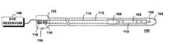
- FIG. 1shows a top view of a tissue-marking device according to an embodiment of the present invention.
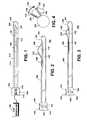
- FIG. 2shows the tissue-marking device of FIG. 1 in a first deployed configuration.
- FIG. 3shows the tissue-marking device of FIG. 1 in a second deployed configuration.
- FIG. 4shows a front view of the tissue-marking device of FIG. 1, to illustrate the operation of the tissue-marking probe.
- FIG. 5Ashows another embodiment of the present invention, in which an intra-tissue probe includes integrated specimen cutting, marking and isolation tools.
- FIG. 5Bshows a cross-section of the intra-tissue probe of FIG. 5A, taken along lines AA′.
- FIG. 6Ashows the intra-tissue probe of FIG. 5A, in which the specimen cutting, marking and isolation tools are shown in a deployed configuration.
- FIG. 6Bshows a cross section of the intra-tissue probe of FIG. 6A, taken along lines BB′.
- FIG. 7shows an intra tissue probe for cutting and marking tissue specimens, according to another embodiment of the present invention.
- FIG. 8shows the probe of FIG. 7, in a first extended configuration.
- FIG. 9shows the probe of FIG. 7, in a second extended configuration.
- FIG. 10Ais a flowchart of a tissue-marking method according to an embodiment of the present invention.
- FIG. 10Bis a flowchart of a tissue-marking method according to another embodiment of the present invention.
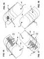
- FIG. 11is a representation of a coagulation-marked tissue specimen, according to an embodiment of the present invention.
- FIG. 12is a representation of the marked tissue specimen of FIG. 11, viewed from another orientation.
- FIG. 13is a representation of the marked tissue specimen of FIG. 11, viewed from another orientation.
- FIG. 14is a representation of the marked tissue specimen of FIG. 11, viewed from another orientation.
- FIG. 15is a representation of a dye-marked tissue specimen, according to another embodiment of the present invention.
- FIG. 16is a representation of the marked tissue specimen of FIG. 15, viewed from another orientation.
- FIG. 17is a representation of the marked tissue specimen of FIG. 15, viewed from another orientation.
- FIG. 18is a representation of the marked tissue specimen of FIG. 15, viewed from another orientation.
- FIG. 19shows a tissue specimen-stabilizing device, according to an embodiment of the present invention.
- FIG. 20shows the tissue specimen-stabilizing device of FIG. 19, in which the tissue stabilization tool is shown in a deployed configuration.
- FIG. 21shows a partial top view of the device of FIGS. 19 and 20.
- FIG. 22shows another example of the distal barbed tip of the tissue specimen stabilization tool of FIGS. 19 - 21 .
- FIG. 1shows a top view of a tissue-marking device according to an embodiment of the present invention.
- the tissue-marking device 100includes a proximal portion 102 and a distal tip 104 .
- the proximal portion 102may include a marking tool actuator 118 and the distal tip 104 may include a tissue-marking tool 106 , which may include a thin flexible hollow ribbon or a thin flexible tube.
- the marking tool 106may be configured to selectively bow out of and to retract within a window 110 defined within the body of the probe 100 when the marking tool actuator 118 is activated.
- the tissue-marking probe 100may also include an internal guide 112 (or may define an internal lumen) to enable the marking tool 106 to slide within the removable cutting probe 100 when marking tool actuator 118 is activated.
- the marking tool actuator 118is shown as a thumb-activated dial in FIGS. 1-3 and 7 - 9 .
- any other means of advancing and retracting the marking tool 106may also advantageously be used within the context of the present invention.
- the tissue-marking probe 100may further include a window slide 108 disposed within the window 110 .
- the proximal end 102 of the probe 100may further include window slide extending means 116 .
- the window slide 108is mechanically coupled to the window slide extending means 116 and is guided within the tissue-marking probe 100 by an internal guide or lumen 114 defined along the length of the probe 100 .
- the window slide 108is configured to selectively cover a portion of the window 110 when the window slide extending means 116 are activated.
- the window slide 108covers a portion of the window 110 to selectively vary the size of the window 110 through which the tissue-marking tool 106 is allowed to extend or bow.
- FIG. 2shows a side view of the tissue-marking 100 probe of FIG. 1 .
- the probe 100is in a configuration wherein the tissue-marking tool 106 is in a bowed or extended state.
- the body of the probe 100may internally define at least one internal dye lumen 146 that is in fluid communication with a dye reservoir 140 , which may be external to the probe 100 as shown in FIG. 1 or internal thereto, as shown in FIGS. 2 and 3.
- the dye reservoir 140is adapted to contain a volume of at least one dye.
- the dye reservoir 140is in fluid communication with the internal dye lumen 146 , so as to deliver dye from the dye reservoir 140 to the tissue-marking tool 106 .
- the tissue-marking tool 106defines at least one dye port 142 .
- Each of the dye ports 142is in fluid communication with the dye lumen(s) 146 defined within the probe 100 .
- a marking actuator 154controls the flow of dye from the dye reservoir 140 to the dye ports 142 .
- the marking actuator 154may include a simple on/off valve to selectively open and cut the flow of dye to the dye ports 142 .
- the marking actuator 154may be pressure sensitive, so as to allow the physician to manually vary the flow of dye through the ports 142 by varying the pressure applied to the marking actuator 154 .
- the probe 100may also define a distal dye extrusion port 144 in fluid communication with the internal lumen 146 and the dye reservoir 140 (through a tributary lumen 147 defined within the probe body, for example).
- FIG. 3shows the probe 100 of FIG. 2 in a configuration wherein the window slide 108 is slid over a greater portion of the window 110 than is the window slide 108 of FIG. 2 .
- the window slide 108effectively decreases the size (shortens the length) of the window 110 from which the tissue-marking tool 106 may bow or extend.
- Carefully choosing the extend to which the window slide 108 covers the window 110allows precise control over the shape of the tissue-marking tool 106 as it bows or extends from the window 110 .
- tissue-marking tool 106precise control over the shape of the tissue-marking tool 106 as it bows out from the window 110 allows the physician to precisely control the manner in which the tissue specimen is marked, as the tissue-marking tool 106 is caused to closely conform to the shape and size of the cut specimen.
- FIG. 4shows a front view of the probe 100 of FIGS. 1, 2 and 3 and illustrates the operation of the tissue-marking probe 100 .
- the probe 100is inserted into the patient's tissue, preferably following the insertion track of the excisional device that cut the specimen (shown at 150 in FIG. 4) from the surrounding tissue.
- Suitable excisional devicesare disclosed, for example, in commonly assigned U.S. Pat. No. 6,022,362, the disclosure of which is incorporated herein by reference in their entireties.
- a split introducermay be used to insert the probe 100 into the patient's soft tissue. The probe 100 is then navigated so that the window 110 is adjacent the cut specimen 150 to be marked.
- the tissue-marking tool 106While rotating the probe body, in a clockwise direction (for example) as shown by the arrow 152 , the tissue-marking tool 106 is extended radially out from the window 110 so as to encompass the previously cut specimen 150 .
- the physicianuses the marking actuator 154 to cause dye 148 to extrude or spray out of the dye extrusion ports 142 and onto the cut specimen 150 .
- the flow of dye 148may be selectively cut on and off on different surfaces of the cut specimen 150 as the probe is rotated, so as to appropriately mark the orientation of the specimen 150 within the surrounding tissue.
- the physicianmay mark (apply dye to) a left superior portion of the surface of the specimen 150 , a right inferior portion thereof and the distal end of the specimen 150 (using the distal dye port 144 , for example). In this manner, the physician may readily reconstruct the orientation of the specimen within the cavity created by the excision of the specimen 150 .
- the tissue specimenmay be simultaneously cut, marked and isolated from the surrounding tissue, all prior to retraction thereof from the patient.
- the probe 500may include a specimen isolator 512 attached to the tissue-marking tool 514 .
- the specimen isolator 512is adapted to isolate the specimen from the surrounding tissue, as soon as the specimen is cut by the tissue-cutting tool 508 .
- the tissue-cutting tool 508may include an RF blade or wire and may be a monopolar or bipolar RF cutting blade or wire.
- the probe 500may include a distal RF tissue-cutting tool 562 disposed in the distal tip 504 of the probe body 560 .
- the tissue-cutting tool 508may be configured to selectively bow out of and back into the same window 510 as the tissue-marking tool 514 bows out of and back into (as shown in FIGS. 5 and 6) or may be configured to bow out of and back into a separate window (not shown) defined within the body of the probe 500 .
- the specimen isolator 512may include a thin flexible film of material. One end of the film may be attached to the body 560 of the probe 500 and another end of the film may be attached to the tissue-marking tool 514 .
- the specimen isolator 512in this manner, is configured to extend radially from the probe body 560 out of the window 510 when and as the tissue-marking tool 514 is bowed.
- the tissue-cutting tool 508 and the assembly including the tissue-marking tool 514 and the specimen isolator 512are actuated by the same tool actuator 546 , the probe 500 may cut and isolate the soft tissue specimen from the surrounding tissue with ease.
- the tissue isolator 512may initially be stowed in a flattened configuration (best shown in FIG. 5B) in a recessed portion 558 defined within the body 560 of the probe 500 .
- a weak and biologically inert adhesivemay be used keep the specimen isolator 512 in its initially flattened state prior to deployment of the marking tool 514 within the patient's tissue.
- the marking tool 514is bowed out of the window 510 defined in the probe body 560
- the specimen isolator 512 attached theretounfolds from the recessed portion 558 and at least partially encapsulates the specimen as it is cut, as shown at FIG. 5 B.
- the cutting tool 508may be deployed independently of the tissue-marking tool 514 —specimen isolator 512 combination. In that case, a complete cut of the specimen may be made within the patient prior to a subsequent tissue isolation and marking operation by an also independently actuated tissue-marking tool 514 and specimen isolator 512 .
- One or more guides or internal lumens 556may be defined within the probe body 560 to guide the tissue-marking tool 514 and/or the tissue-cutting tool 580 .
- tissue-marking and cutting tools 514 , 508are constrained in their path along the length of the probe 500 and attached at their distal ends to or near the distal tip 504 of the probe 500 , when the tools 514 , 508 are pushed in the distal direction, they tend to bow out of the window 510 , which provides the only outlet for such bowing.
- the cutting tool 508may be caused to bow out of and to extend outwardly from the window 510 when actuated by the tool actuator 546 and caused to cut tissue coming into contact therewith.
- the specimen isolator and the tissue-marking tool 514may also be correspondingly deployed by the same (or a separate) tool actuator 546 and caused to precisely follow the trailing edge of the cutting tool 508 (thereby following in its path) as it cuts the soft tissue.
- the marking actuator 554may be selectively actuated by the physician to mark the tissue specimen with dye from the dye extrusion ports 542 as it is being isolated.
- the probe 500may also advantageously include a distal dye port 544 to mark the distal end of the specimen.
- a dye reservoir 140may be disposed within the proximal end of the probe 500 or may be disposed external thereto.
- a suitable biologically inert propellantmay also be present in the dye reservoir 140 to insure that the dye is appropriately sprayed onto the specimen to be marked. Suitable propellants include, for example, carbon dioxide and XXX.
- Several dye reservoirs 140may be used to spray dyes of different colors onto the specimen. In that case, each color of dye may be delivered to all or selected ones of the dye ports 142 through a separate lumen defined within the probe body 560 .
- the probe 500may then be safely retracted from the patient's soft tissue (such as the breast, for example).
- soft tissuesuch as the breast, for example.
- the probability of seeding the surrounding tissue with potentially abnormal cellsis markedly decreased.
- This probabilityis also further decreased, as the probe 500 according to the present invention allows the surgeon to obtain adequate margins of healthy tissue surrounding the target lesion by choosing the degree of bowing and extension of the cutting tool 508 under (external or intra-tissue ultrasonic guidance, for example). In this manner, the integrity of the lesion itself is not violated, thereby maintaining tissue architecture intact.
- tissue isolator 512is preferably formed of a thin and flexible film, it is able to lay substantially flat against the outer surface of the probe body 500 or within a slightly recessed portion 558 of the probe body 500 .
- the tissue isolator 512therefore, offers little additional drag and resistance to the probe 500 as it is inserted into the incision made in the patient's skin during or prior to the procedure.
- the material for the tissue isolator 512may be a flexible semi-porous or non-porous material.
- the tissue isolatormay include a synthetic polymer such as a polyorganosiloxane or a polydiorganosiloxane.
- the materialmay include an inorganic elastomer, such as a silicone elastomer.
- the tissue isolatormay also include a teraphthalate (PET), a tetrafluoroethylene (TFE) and/or or a polytetrafluoroethylene (PTFE).
- PETteraphthalate
- TFEtetrafluoroethylene
- PTFEpolytetrafluoroethylene
- the tissue isolatormay have a laminate structure and may include one or more reinforcing layers including, for example, a polyimid, a polyester, Kevlar(R) and/or a polymer such as the M5 fiber manufactured by Magellan Systems International of Arnhem, The Netherlands, for example.
- the tissue isolatorwill have a high tensile strength (over 1,000 psi) and a high tear resistance.
- the material selected for the tissue isolatorwill be able to withstand temperatures in excess of about 180 C., for example.
- the tissue isolator 512may be formed of a material other than specifically enumerated herein while remaining within the spirit of the present invention.
- the shape and size of the tissue isolator 512are such as to minimize drag on the probe 500 as it is inserted and rotated into the tissue.
- FIGS. 7-9show an intra-tissue probe 700 , according to another embodiment of the present invention.
- the description of the structures corresponding to reference numbers 102 , 118 , 116 , 114 , 112 , 108 , 110 and 104is presented above with respect to FIGS. 1-3 and is incorporated herein by reference.
- Reference numeral 524corresponds to an RF cutting tool (either monopolar or bipolar) that is configured to selectively bow out of and back into the window 110 defined within the probe 700 .
- the probe cutting tool 524is electrically coupled to an RF power source 126 such as are known in the art.
- the probe 700may be utilized alone, or in combination with a specimen isolator, such as shown at 512 in FIGS. 5A through 6B.
- a specimenmay be marked as it is being cut or after a partial or complete cut has been made by the tissue-cutting tool 524 .
- a soft tissue excisional methodincludes a step of disposing a probe (such as shown at 700 ) within tissue from which a tissue specimen is to be taken, the probe 700 including an RF tissue cutting tool (such as shown at 524 ) configured to selectively bow out of and back into a window 110 defined near a distal tip of the probe 700 .
- the probe 700may then be rotated while RF energy is applied to the RF cutting tool 524 .
- the cutting tool 524may then be selectively bowed out of the window 110 to cut the specimen from the tissue while the probe 700 is rotated. Selected portions of the surface of the specimen may then be selectively coagulated by the RF cutting tool 524 . By judiciously choosing the portions of the surface of the specimen that are coagulated (and/or cauterized), the orientation of the specimen within the body is may be reconstructed after the cut specimen is excised from the body, even if the cut specimen is twisted and/or deformed during retraction thereof from the patient or during subsequent handling.
- the cutting and marking described abovemay also be combined with tissue isolation as described relative to FIGS. 5A through 6B and/or with other tissue isolation structures and techniques. As shown in FIG.
- the body of the probe 700may also define a plurality of through holes 138 in fluid communication with an internal lumen 140 defined within the probe 700 .
- the internal lumen 140may be in fluid communication with a proximal port 142 disposed at the proximal end 102 of the probe 700 .
- the through holes 138may be utilized for the delivery of a fluid to the patient during the cutting, isolating or marking procedure, such as antibiotic agents, analgesic agents or most any pharmaceutical agent. Such agents may be administered to the patient from the port 142 .
- the port 142may be coupled to suction and the through holes 138 may be utilized to suction out the excisional site of smoke, blood or other bodily fluids during or after the excisional procedure.
- more than one port 142may be provided in the proximal portion 102 and more than one lumen 140 may be defined along the length of the probe 700 .
- the additional lumenmay be in fluid communication with selected through holes 138 .
- FIGS. 10A and 10Bare flowcharts of the excisional, marking and tissue isolation methods according to embodiments of the present invention.
- step S 10 A 1calls for a probe, such as shown in FIGS. 1 through 6B, to be inserted into the patient's soft tissue.
- a probesuch as described herein may be inserted into breast tissue.
- the probeis then rotated. If the specimen is not already cut from the main tissue mass in which the probe is inserted, a tissue-cutting tool (such as shown at 508 or 524 ) may be activated and a complete or partial cut of the specimen may be made.
- a tissue-cutting toolsuch as shown at 508 or 524
- Step S 10 A 3calls for the tissue-marking tool (such as shown at 106 or 514 ) to be deployed, so that the path taken by the tissue-marking tool 106 , 514 follows the path taken by the cutting tool 508 , 524 .
- the specimenmay be cut by a probe such as shown at 700 , after which a tissue-marking specific probe, such as shown at FIGS. 1-3, may be inserted into the soft tissue after retraction of the probe 700 has finished its cut and has been removed.
- a combination probesuch as shown at FIGS. 6A through 6B may be employed to cut, mark and isolate the specimen.
- One or more dyesmay be extruded from the dye ports 142 to mark the specimen either during the cutting thereof or after the specimen is completely severed from the surrounding tissue.
- the specimenmay be concurrently isolated using the specimen isolator 512 attached to the probe body and the tissue-marking tool 514 or may be isolated after the specimen is completely cut. After the specimen is cut, marked and/or isolated, it may be removed from the patient, by retracting the probe from the excision site and form the patient, as shown at S 10 A 4 .
- FIG. 10Bother embodiments of the present invention call for the insertion of a probe, such as shown at FIGS. 6A through 9 into tissue, as outlined at S 10 B 1 .
- RF powermay be applied to the cutting tool (such as shown at 508 , 524 ) and the cutting tool deployed (i.e., bowed out of window 110 ) while the probe 500 , 700 is rotated, as shown at S 10 B 2 .
- the tissue isolator 512(if present) may be deployed to isolate the cut tissue from the surrounding tissue.
- Selected portions of the surface of the partially of fully cut specimenmay then be marked by coagulating (or cauterizing) the selected portions using the RF cutting tool 508 , 524 .
- the cut, marked and optionally isolated specimenmay then be removed from the excision site and the patient by retracting the probe, as outlined in step S 10 B 4 .
- FIGS. 11-14each show a representation of a same coagulation-marked tissue specimen 800 in different orientations, according to an embodiment of the present invention.
- the tissue specimen 800is shown as marked using one of the probes according to the present invention, as shown in FIGS. 1-9.
- the tissue specimen 800defines 6 surfaces: the left superior surface LS best seen in FIG. 11, the right superior surface RS best seen in FIG. 12, the left inferior surface LI best seen in FIG. 13, the right inferior surface RI best seen in FIG. 14, the proximal surface P and the distal surface D hidden in FIGS. 11-14.
- the physicianmay mark selected portions of the surface of the specimen 800 .
- the RS surface of the specimen 800may be marked by coagulating or cauterizing it, in a distinctive pattern such as, for example, two lines.
- selected portions of the LS surface of the specimen 800may be coagulated or cauterized to create three coagulation or cauterization lines.
- the LI surface thereofmay be selectively coagulated or cauterized. In this manner, the original orientation of the specimen 800 may be readily reconstructed, even after the specimen 800 is removed from the patient, twisted and/or otherwise deformed during a pathological examination, for example.
- the RF power delivered to the portion of the surface of the cut specimen 800 by the RF cutting tool 508 , 524may be momentarily increased from the power normally applied thereto during the cutting procedure.
- the coagulating or cauterizationis carried out by momentarily maintaining the RF cutting tool 508 , 524 immobile or substantially immobile on the selected portion of the surface of the specimen 800 while the RF power delivered to the RF cutting tool 508 , 524 is maintained constant.
- the pattern of coagulation or cauterization lines shown in FIGS. 11-14is but an illustrative example, and that other combinations of surfaces of the specimen 800 may be marked (or marked differently than shown in FIGS. 11 - 14 ), it being only necessary to distinctively mark a sufficient number of surfaces so as to enable a later reconstruction of the orientation of the specimen 800 within the excision cavity.
- FIGS. 15-18each show a representation of a same dye-marked tissue specimen 900 in different orientations, according to an embodiment of the present invention.
- selected surfaces of the specimen 900are marked with a dye, using the marking tool 106 and 514 and the distal port 144 , 544 in FIGS. 1-6B.
- dyemay be applied to selected surfaces of the specimen 900 so as to enable a ready reconstruction of the orientation thereof after the specimen 900 is removed from the patient.
- the RS and LI surfaces of the specimen 900may be marked with dye using the marking tool 106 , 514 .
- the D surfacemay be marked with the distal dye port 144 , 544 .
- Marking three selected surfaces of the specimen 900may be sufficient to enable the physician to reconstruct the original orientation of the specimen 900 , even of the specimen 900 has been twisted, compressed and/or otherwise deformed after excision thereof from the patient.
- the dye markingsmay be of the same or different colors.
- the dye applied by the marking tool 106 , 514may include any biologically inert dye, such as Methylene Blue, Congo Red and/or Lymphazurin® Blue, for example.
- the dyemay be delivered at a selectable graduated rate to the surface of the specimen 900 .
- the dyemay be delivered darker to a first portion of the surface of the specimen 900 and delivered relatively lighter to a second portion of the surface of the specimen 900 .
- FIGS. 15 and 17show the direction of rotation of the tissue-marking tool 106 , 514 as it sweeps over the specimen 900 .
- the dyemay become smeared, as shown in FIGS. 15 and 17.
- the direction of such smearingmay provide the physician with yet another indication of the original orientation of the specimen 900 within the excision cavity within the patient.
- Dye-based markings and coagulation-based markingsmay be advantageously combined. For example, selected surfaces of a specimen may be marked using coagulation or cauterization, while the distal surface of the specimen may be marked with dye, using the distal dye port 144 , 544 . Other combinations are possible, and all such combinations are deemed to fall within the scope of the present invention.
- FIGS. 19, 20 and 21show another embodiment 1000 of the present invention, which allows the orientation of the specimen to be preserved during extraction thereof from the patient.
- Reference numerals 102 , 104 , 116 , 118 , 108 and 144are structures that correspond to like numbered structures in FIGS. 1-3. The description thereof is, therefore, not repeated here explicitly, but is incorporated herewith by reference.
- FIGS. 19-21show a probe 1000 that includes a probe body 1016 , the probe body 1016 defining an internal tool lumen 1004 that emerges from the probe body 1016 at a tool port 1010 defined near the distal tip 104 of the probe body 1016 .
- a tool actuator 1002may be disposed near the proximal end 102 of the probe 1000 .
- the tool actuator 1002is mechanically coupled to a tissue specimen stabilization tool 1008 disposed within the internal tool lumen 1004 .
- the stabilization tool 1008may include a barbed tip (such as shown at 1012 or 1014 in FIG. 22, for example).
- the stabilization tool 1008is adapted to selectively slide within the tool lumen 1004 and extend out of the tool port 1010 to penetrate and stabilize tissue (such as a cut specimen 1014 , for example) adjacent the tool port 1010 .
- the internal tool lumen 1004may be generally parallel to a longitudinal axis of the probe body 1016 near the proximal end 102 thereof and may curve away from the axis near the distal tip 104 of the probe body 1016 to emerge at the tool port 1010 .
- the probe 1000may also include a cutting tool 1006 (an RF cutting tool, for example) disposed near the distal tip 104 of the probe body 1016 .
- the barbed tip 1012 of the stabilization tool 1008may be configured to expand when it emerges from the tool port 1010 . Indeed, FIG. 19 shows the barbed tip 1012 of the stabilization tool 1008 in a folded configuration, whereas FIG. 20 shows the barbed tip 1012 in a deployed configuration. In such a deployed configuration, the barbed tip 1012 hooks into and securely holds the specimen 1014 , much like a harpoon.
- the barbed tip 1012 of the stabilization toolmay include or be formed of an elastic material, such as a Nitinol® or similar super elastic alloys, for example.
- the barbed tipmay emerge from the probe 1000 within a hole 1018 defined in the cutting tool 1006 as shown at FIG. 21 or may emerge therefrom adjacent thereto, for example. Other placements of the tool port 1010 are readily envisaged.
- the barbed tip 1012 , 1014 of the stabilization tool 1008may be shaped as shown in FIGS. 19, 20 or 22 . Other designs for the barbed tip 1012 , 1014 will occur to those of skill in this art, and all such alternative designs are deemed to fall within the scope of the present invention.
- the probes and devices described hereinare preferably configured for a single use and are disposable. Alternatively, the probes and devices disclosed herein may be sterilizable and re-usable. Moreover, the probes and devices described herein may be used alone or in combination with other soft tissue excisional systems, such as described in commonly assigned and co-pending application entitled “Excisional Biopsy Devices And Methods” filed on May 4, 2000 and assigned Ser. No. 09/565,611, the disclosure of which is also incorporated herein in its entirety. While the present inventions are well suited to procedures on breast tissue, they are equally well suited to procedures on most any other soft tissue, such as lung tissue, thyroid tissue, liver tissue and/or other tissues.
Landscapes
- Health & Medical Sciences (AREA)
- Life Sciences & Earth Sciences (AREA)
- Engineering & Computer Science (AREA)
- Surgery (AREA)
- General Health & Medical Sciences (AREA)
- Veterinary Medicine (AREA)
- Public Health (AREA)
- Animal Behavior & Ethology (AREA)
- Molecular Biology (AREA)
- Medical Informatics (AREA)
- Biomedical Technology (AREA)
- Heart & Thoracic Surgery (AREA)
- Neurosurgery (AREA)
- Physics & Mathematics (AREA)
- Otolaryngology (AREA)
- Neurology (AREA)
- Nuclear Medicine, Radiotherapy & Molecular Imaging (AREA)
- Plasma & Fusion (AREA)
- Pathology (AREA)
- Surgical Instruments (AREA)
- Sampling And Sample Adjustment (AREA)
Abstract
Description
Claims (17)
Priority Applications (6)
| Application Number | Priority Date | Filing Date | Title |
|---|---|---|---|
| US10/155,570US6780179B2 (en) | 2002-05-22 | 2002-05-22 | Methods and systems for in situ tissue marking and orientation stabilization |
| PCT/US2003/011847WO2003099151A1 (en) | 2002-05-22 | 2003-04-17 | Methods and devices for in situ tissue marking and orientation stabilization |
| EP03728426AEP1505918A4 (en) | 2002-05-22 | 2003-04-17 | Methods and devices for in situ tissue marking and orientation stabilization |
| AU2003234120AAU2003234120A1 (en) | 2002-05-22 | 2003-04-17 | Methods and devices for in situ tissue marking and orientation stabilization |
| US10/871,790US7553310B2 (en) | 2002-05-22 | 2004-06-17 | Methods and systems for in situ tissue marking and orientation stabilization |
| US11/737,382US20070198010A1 (en) | 2002-05-22 | 2007-04-19 | Methods and systems for in situ tissue marking and orientation stabilization |
Applications Claiming Priority (1)
| Application Number | Priority Date | Filing Date | Title |
|---|---|---|---|
| US10/155,570US6780179B2 (en) | 2002-05-22 | 2002-05-22 | Methods and systems for in situ tissue marking and orientation stabilization |
Related Child Applications (1)
| Application Number | Title | Priority Date | Filing Date |
|---|---|---|---|
| US10/871,790DivisionUS7553310B2 (en) | 2002-05-22 | 2004-06-17 | Methods and systems for in situ tissue marking and orientation stabilization |
Publications (2)
| Publication Number | Publication Date |
|---|---|
| US20030220640A1 US20030220640A1 (en) | 2003-11-27 |
| US6780179B2true US6780179B2 (en) | 2004-08-24 |
Family
ID=29549103
Family Applications (3)
| Application Number | Title | Priority Date | Filing Date |
|---|---|---|---|
| US10/155,570Expired - Fee RelatedUS6780179B2 (en) | 2002-05-22 | 2002-05-22 | Methods and systems for in situ tissue marking and orientation stabilization |
| US10/871,790Expired - Fee RelatedUS7553310B2 (en) | 2002-05-22 | 2004-06-17 | Methods and systems for in situ tissue marking and orientation stabilization |
| US11/737,382AbandonedUS20070198010A1 (en) | 2002-05-22 | 2007-04-19 | Methods and systems for in situ tissue marking and orientation stabilization |
Family Applications After (2)
| Application Number | Title | Priority Date | Filing Date |
|---|---|---|---|
| US10/871,790Expired - Fee RelatedUS7553310B2 (en) | 2002-05-22 | 2004-06-17 | Methods and systems for in situ tissue marking and orientation stabilization |
| US11/737,382AbandonedUS20070198010A1 (en) | 2002-05-22 | 2007-04-19 | Methods and systems for in situ tissue marking and orientation stabilization |
Country Status (4)
| Country | Link |
|---|---|
| US (3) | US6780179B2 (en) |
| EP (1) | EP1505918A4 (en) |
| AU (1) | AU2003234120A1 (en) |
| WO (1) | WO2003099151A1 (en) |
Cited By (39)
| Publication number | Priority date | Publication date | Assignee | Title |
|---|---|---|---|---|
| US20040024396A1 (en)* | 1999-12-27 | 2004-02-05 | Eggers Philip E. | Electrosurgical accessing of tissue with controlled collateral thermal phenomena |
| US20040255739A1 (en)* | 2003-06-18 | 2004-12-23 | Rubicor Medical, Inc. | Methods and devices for cutting and collecting soft tissue |
| US20070038145A1 (en)* | 2004-11-22 | 2007-02-15 | Inrad, Inc. | Post Decompression Marker Introducer System |
| US20070083220A1 (en)* | 2004-06-09 | 2007-04-12 | Ovalum Ltd. | Blood vessel occlusion auger |
| US20100030149A1 (en)* | 2006-10-23 | 2010-02-04 | C.R. Bard, Inc. | Breast marker |
| US8157862B2 (en) | 1997-10-10 | 2012-04-17 | Senorx, Inc. | Tissue marking implant |
| US8177792B2 (en) | 2002-06-17 | 2012-05-15 | Senorx, Inc. | Plugged tip delivery tube for marker placement |
| US8219182B2 (en) | 1999-02-02 | 2012-07-10 | Senorx, Inc. | Cavity-filling biopsy site markers |
| US8224424B2 (en) | 1999-02-02 | 2012-07-17 | Senorx, Inc. | Tissue site markers for in vivo imaging |
| US8311610B2 (en) | 2008-01-31 | 2012-11-13 | C. R. Bard, Inc. | Biopsy tissue marker |
| US20120316463A1 (en)* | 2007-07-16 | 2012-12-13 | Dune Medical Devices Ltd. | Medical device and method for use in tissue characterization and treatment |
| US8361082B2 (en) | 1999-02-02 | 2013-01-29 | Senorx, Inc. | Marker delivery device with releasable plug |
| US8401622B2 (en) | 2006-12-18 | 2013-03-19 | C. R. Bard, Inc. | Biopsy marker with in situ-generated imaging properties |
| US8447386B2 (en) | 2003-05-23 | 2013-05-21 | Senorx, Inc. | Marker or filler forming fluid |
| US8486028B2 (en) | 2005-10-07 | 2013-07-16 | Bard Peripheral Vascular, Inc. | Tissue marking apparatus having drug-eluting tissue marker |
| US8498693B2 (en) | 1999-02-02 | 2013-07-30 | Senorx, Inc. | Intracorporeal marker and marker delivery device |
| US8579931B2 (en) | 1999-06-17 | 2013-11-12 | Bard Peripheral Vascular, Inc. | Apparatus for the percutaneous marking of a lesion |
| US8594768B2 (en) | 2004-11-01 | 2013-11-26 | Michael J. Phillips | Surgical system with clips for identifying the orientation of a tissue sample |
| US8626269B2 (en) | 2003-05-23 | 2014-01-07 | Senorx, Inc. | Fibrous marker and intracorporeal delivery thereof |
| US8634899B2 (en) | 2003-11-17 | 2014-01-21 | Bard Peripheral Vascular, Inc. | Multi mode imaging marker |
| US8670818B2 (en) | 2008-12-30 | 2014-03-11 | C. R. Bard, Inc. | Marker delivery device for tissue marker placement |
| US8668737B2 (en) | 1997-10-10 | 2014-03-11 | Senorx, Inc. | Tissue marking implant |
| US8685049B2 (en) | 2010-11-18 | 2014-04-01 | Rex Medical L.P. | Cutting wire assembly for use with a catheter |
| US8685050B2 (en) | 2010-10-06 | 2014-04-01 | Rex Medical L.P. | Cutting wire assembly for use with a catheter |
| US8702736B2 (en) | 2010-11-22 | 2014-04-22 | Rex Medical L.P. | Cutting wire assembly for use with a catheter |
| US8718745B2 (en) | 2000-11-20 | 2014-05-06 | Senorx, Inc. | Tissue site markers for in vivo imaging |
| USD715442S1 (en) | 2013-09-24 | 2014-10-14 | C. R. Bard, Inc. | Tissue marker for intracorporeal site identification |
| USD715942S1 (en) | 2013-09-24 | 2014-10-21 | C. R. Bard, Inc. | Tissue marker for intracorporeal site identification |
| USD716451S1 (en) | 2013-09-24 | 2014-10-28 | C. R. Bard, Inc. | Tissue marker for intracorporeal site identification |
| USD716450S1 (en) | 2013-09-24 | 2014-10-28 | C. R. Bard, Inc. | Tissue marker for intracorporeal site identification |
| US9149341B2 (en) | 1999-02-02 | 2015-10-06 | Senorx, Inc | Deployment of polysaccharide markers for treating a site within a patient |
| US9282991B2 (en) | 2010-10-06 | 2016-03-15 | Rex Medical, L.P. | Cutting wire assembly with coating for use with a catheter |
| US9327061B2 (en) | 2008-09-23 | 2016-05-03 | Senorx, Inc. | Porous bioabsorbable implant |
| US9579077B2 (en) | 2006-12-12 | 2017-02-28 | C.R. Bard, Inc. | Multiple imaging mode tissue marker |
| US9820824B2 (en) | 1999-02-02 | 2017-11-21 | Senorx, Inc. | Deployment of polysaccharide markers for treating a site within a patent |
| US9848956B2 (en) | 2002-11-18 | 2017-12-26 | Bard Peripheral Vascular, Inc. | Self-contained, self-piercing, side-expelling marking apparatus |
| US9901362B2 (en) | 2007-07-16 | 2018-02-27 | Dune Medical Devices Ltd. | Medical device and method for use in tissue characterization and treatment |
| US9999353B2 (en) | 2007-07-16 | 2018-06-19 | Dune Medical Devices Ltd. | Medical device and method for use in tissue characterization and treatment |
| US10342635B2 (en) | 2005-04-20 | 2019-07-09 | Bard Peripheral Vascular, Inc. | Marking device with retractable cannula |
Families Citing this family (9)
| Publication number | Priority date | Publication date | Assignee | Title |
|---|---|---|---|---|
| US7517348B2 (en)* | 1998-09-03 | 2009-04-14 | Rubicor Medical, Inc. | Devices and methods for performing procedures on a breast |
| US20060090658A1 (en) | 2004-11-01 | 2006-05-04 | Michael Phillips | Tissue marking system |
| US7799024B2 (en)* | 2005-12-29 | 2010-09-21 | Boston Scientific Scimed, Inc. | Tissue ablation probes and methods for treating osteoid osteomas |
| USD565743S1 (en) | 2007-04-12 | 2008-04-01 | Vector Surgical, Inc. | Surgical container with applicators |
| WO2009067192A1 (en)* | 2007-11-19 | 2009-05-28 | The Trustees Of Columbia University In The City Of New York | Skin marking device and suture holder |
| WO2013121331A1 (en)* | 2012-02-13 | 2013-08-22 | Koninklijke Philips N.V. | Photonic probe apparatus with integrated tissue marking facility |
| EP2986229A4 (en)* | 2013-04-16 | 2016-09-28 | Transmed7 Llc | Methods, devices and therapeutic platform for automated, selectable, soft tissue resection |
| ES2797849B2 (en)* | 2019-06-03 | 2021-04-29 | Marcano Nelson Gabriel Cohen | INSTRUMENT FOR THE OPTIMIZATION OF THE CARVING OF SURGICAL PIECES OF PATHOLOGICAL ANATOMY |
| US20230190330A1 (en)* | 2020-06-18 | 2023-06-22 | Boston Scientific Medical Device Limited | Energy-emitting devices for elongated medical assembly |
Citations (52)
| Publication number | Priority date | Publication date | Assignee | Title |
|---|---|---|---|---|
| GB1214707A (en) | 1968-04-18 | 1970-12-02 | Electronic & X Ray Applic Ltd | Improvements in or relating to ancillary apparatus for use with x-ray apparatus |
| US3971950A (en) | 1975-04-14 | 1976-07-27 | Xerox Corporation | Independent compression and positioning device for use in mammography |
| DE2610111A1 (en) | 1976-03-11 | 1977-09-15 | Friedrich Guenter Schwarz | Body holder for X:ray examination - has housing permeable to X:rays over part of body and connected to fluid source |
| US4130112A (en) | 1976-11-15 | 1978-12-19 | The United States Of America As Represented By The Administrator Of The National Aeronautics And Space Administration | Coupling apparatus for ultrasonic medical diagnostic system |
| US4347850A (en) | 1980-03-19 | 1982-09-07 | Indianapolis Center For Advanced Research, Inc. | Direct water coupling device for ultrasound breast scanning in a supine position |
| US4434799A (en) | 1982-03-02 | 1984-03-06 | Siemens Ag | Ultrasound apparatus for medical examinations |
| US4509368A (en) | 1981-06-22 | 1985-04-09 | The Commonwealth Of Australia | Ultrasound tomography |
| US4563768A (en) | 1983-07-11 | 1986-01-07 | University Of Virginia Alumni Patents Foundations | Mamographic device using localized compression cone |
| US4691333A (en) | 1985-12-27 | 1987-09-01 | Gabriele Joseph M | Breast compression and needle localization apparatus |
| US4829184A (en) | 1984-06-25 | 1989-05-09 | Nelson Robert S | Reflective, transmissive high resolution imaging apparatus |
| US5009660A (en) | 1989-09-15 | 1991-04-23 | Visx, Incorporated | Gas purging, eye fixation hand piece |
| US5056523A (en) | 1989-11-22 | 1991-10-15 | Board Of Regents, The University Of Texas System | Precision breast lesion localizer |
| DE4037387A1 (en) | 1990-11-22 | 1992-05-27 | Kari Dr Richter | Object imaging display for ultrasonic sonic scanning computer tomograph - superimposes echoes of primary radiation into summation image |
| US5171321A (en) | 1992-03-09 | 1992-12-15 | Davis Joseph P | Nipple prosthesis and method of making the same |
| US5308321A (en) | 1992-05-05 | 1994-05-03 | Castro Donna J | Retainer assisted by vacuum expansion system |
| US5386447A (en) | 1992-09-23 | 1995-01-31 | Fischer Imaging Corporation | Mammographic screening and biopsy apparatus |
| US5409497A (en) | 1991-03-11 | 1995-04-25 | Fischer Imaging Corporation | Orbital aiming device for mammo biopsy |
| US5437280A (en) | 1993-09-20 | 1995-08-01 | Hussman; Karl L. | Magnetic resonance breast localizer |
| WO1995021582A1 (en) | 1994-02-15 | 1995-08-17 | Hussman Karl L | Localizer |
| US5451789A (en) | 1993-07-19 | 1995-09-19 | Board Of Regents, The University Of Texas System | High performance positron camera |
| US5590166A (en) | 1995-12-28 | 1996-12-31 | Instrumentarium Corporation | Mammography unit |
| US5649923A (en)* | 1988-10-24 | 1997-07-22 | The General Hospital Corporation | Catheter devices for delivering laser energy |
| US5660185A (en) | 1995-04-13 | 1997-08-26 | Neovision Corporation | Image-guided biopsy apparatus with enhanced imaging and methods |
| US5662109A (en) | 1990-12-14 | 1997-09-02 | Hutson; William H. | Method and system for multi-dimensional imaging and analysis for early detection of diseased tissue |
| US5702405A (en) | 1994-11-30 | 1997-12-30 | Siemens Aktiengesellschaft | Stereotactic auxiliary attachment for a tomography apparatus for tomogram guided implementation of a biopsy |
| US5706327A (en) | 1996-02-09 | 1998-01-06 | Trex Medical Corporation | Method and apparatus for mammographic compression |
| US5776177A (en) | 1992-12-21 | 1998-07-07 | Macwhinnie; Virginia | C-shaped heat pack for thermal treatment of breast |
| US5805665A (en) | 1995-06-05 | 1998-09-08 | Nelson; Robert S. | Anthropomorphic mammography phantoms |
| US5810742A (en) | 1994-10-24 | 1998-09-22 | Transcan Research & Development Co., Ltd. | Tissue characterization based on impedance images and on impedance measurements |
| US5820552A (en) | 1996-07-12 | 1998-10-13 | United States Surgical Corporation | Sonography and biopsy apparatus |
| US5855554A (en) | 1997-03-17 | 1999-01-05 | General Electric Company | Image guided breast lesion localization device |
| US5860934A (en) | 1992-12-21 | 1999-01-19 | Artann Corporation | Method and device for mechanical imaging of breast |
| US5868673A (en) | 1995-03-28 | 1999-02-09 | Sonometrics Corporation | System for carrying out surgery, biopsy and ablation of a tumor or other physical anomaly |
| US5876339A (en) | 1997-01-09 | 1999-03-02 | Lemire; Robert | Apparatus for optical breast imaging |
| US5879357A (en) | 1995-10-20 | 1999-03-09 | United States Surgical Corporation | Apparatus for marking tissue location |
| US5899865A (en) | 1988-12-21 | 1999-05-04 | Non-Invasive Technology, Inc. | Localization of abnormal breast tissue using time-resolved spectroscopy |
| US5902310A (en) | 1996-08-12 | 1999-05-11 | Ethicon Endo-Surgery, Inc. | Apparatus and method for marking tissue |
| US5999836A (en) | 1995-06-06 | 1999-12-07 | Nelson; Robert S. | Enhanced high resolution breast imaging device and method utilizing non-ionizing radiation of narrow spectral bandwidth |
| US5997509A (en) | 1998-03-06 | 1999-12-07 | Cornell Research Foundation, Inc. | Minimally invasive gene therapy delivery device and method |
| US6022362A (en)* | 1998-09-03 | 2000-02-08 | Rubicor Medical, Inc. | Excisional biopsy devices and methods |
| WO2000008647A1 (en) | 1998-08-04 | 2000-02-17 | Koninklijke Philips Electronics N.V. | Method for reproducing a recording signal with positioning means |
| US6056700A (en)* | 1998-10-13 | 2000-05-02 | Emx, Inc. | Biopsy marker assembly and method of use |
| US6068638A (en) | 1995-10-13 | 2000-05-30 | Transvascular, Inc. | Device, system and method for interstitial transvascular intervention |
| US6077231A (en) | 1996-06-14 | 2000-06-20 | United States Surgical Corporation | Apparatus and method for localizing and removing tissue |
| US6152899A (en)* | 1996-03-05 | 2000-11-28 | Vnus Medical Technologies, Inc. | Expandable catheter having improved electrode design, and method for applying energy |
| US6220248B1 (en)* | 1998-10-21 | 2001-04-24 | Ethicon Endo-Surgery, Inc. | Method for implanting a biopsy marker |
| US6432064B1 (en)* | 2001-04-09 | 2002-08-13 | Ethicon Endo-Surgery, Inc. | Biopsy instrument with tissue marking element |
| US6440147B1 (en)* | 1998-09-03 | 2002-08-27 | Rubicor Medical, Inc. | Excisional biopsy devices and methods |
| US6454727B1 (en)* | 1998-03-03 | 2002-09-24 | Senorx, Inc. | Tissue acquisition system and method of use |
| US6517498B1 (en)* | 1998-03-03 | 2003-02-11 | Senorx, Inc. | Apparatus and method for tissue capture |
| US6540695B1 (en)* | 1998-04-08 | 2003-04-01 | Senorx, Inc. | Biopsy anchor device with cutter |
| US6626903B2 (en)* | 1997-07-24 | 2003-09-30 | Rex Medical, L.P. | Surgical biopsy device |
Family Cites Families (7)
| Publication number | Priority date | Publication date | Assignee | Title |
|---|---|---|---|---|
| US5593851A (en)* | 1994-04-01 | 1997-01-14 | Chek-Med Systems, Inc. | Test kid for the rapid detection of helicobacter pylori in gastric biopsy tissue |
| JPH10508504A (en)* | 1994-09-16 | 1998-08-25 | バイオプシス メディカル インコーポレイテッド | Method and apparatus for identifying and marking tissue |
| US6331166B1 (en)* | 1998-03-03 | 2001-12-18 | Senorx, Inc. | Breast biopsy system and method |
| US6161034A (en)* | 1999-02-02 | 2000-12-12 | Senorx, Inc. | Methods and chemical preparations for time-limited marking of biopsy sites |
| US6296639B1 (en)* | 1999-02-12 | 2001-10-02 | Novacept | Apparatuses and methods for interstitial tissue removal |
| US6607528B1 (en)* | 1999-06-22 | 2003-08-19 | Senorx, Inc. | Shapeable electrosurgical scalpel |
| US6546935B2 (en)* | 2000-04-27 | 2003-04-15 | Atricure, Inc. | Method for transmural ablation |
- 2002
- 2002-05-22USUS10/155,570patent/US6780179B2/ennot_activeExpired - Fee Related
- 2003
- 2003-04-17WOPCT/US2003/011847patent/WO2003099151A1/ennot_activeApplication Discontinuation
- 2003-04-17EPEP03728426Apatent/EP1505918A4/ennot_activeWithdrawn
- 2003-04-17AUAU2003234120Apatent/AU2003234120A1/ennot_activeAbandoned
- 2004
- 2004-06-17USUS10/871,790patent/US7553310B2/ennot_activeExpired - Fee Related
- 2007
- 2007-04-19USUS11/737,382patent/US20070198010A1/ennot_activeAbandoned
Patent Citations (56)
| Publication number | Priority date | Publication date | Assignee | Title |
|---|---|---|---|---|
| GB1214707A (en) | 1968-04-18 | 1970-12-02 | Electronic & X Ray Applic Ltd | Improvements in or relating to ancillary apparatus for use with x-ray apparatus |
| US3971950A (en) | 1975-04-14 | 1976-07-27 | Xerox Corporation | Independent compression and positioning device for use in mammography |
| DE2610111A1 (en) | 1976-03-11 | 1977-09-15 | Friedrich Guenter Schwarz | Body holder for X:ray examination - has housing permeable to X:rays over part of body and connected to fluid source |
| US4130112A (en) | 1976-11-15 | 1978-12-19 | The United States Of America As Represented By The Administrator Of The National Aeronautics And Space Administration | Coupling apparatus for ultrasonic medical diagnostic system |
| US4347850A (en) | 1980-03-19 | 1982-09-07 | Indianapolis Center For Advanced Research, Inc. | Direct water coupling device for ultrasound breast scanning in a supine position |
| US4509368A (en) | 1981-06-22 | 1985-04-09 | The Commonwealth Of Australia | Ultrasound tomography |
| US4434799A (en) | 1982-03-02 | 1984-03-06 | Siemens Ag | Ultrasound apparatus for medical examinations |
| US4563768A (en) | 1983-07-11 | 1986-01-07 | University Of Virginia Alumni Patents Foundations | Mamographic device using localized compression cone |
| US4829184A (en) | 1984-06-25 | 1989-05-09 | Nelson Robert S | Reflective, transmissive high resolution imaging apparatus |
| US4691333A (en) | 1985-12-27 | 1987-09-01 | Gabriele Joseph M | Breast compression and needle localization apparatus |
| US5649923A (en)* | 1988-10-24 | 1997-07-22 | The General Hospital Corporation | Catheter devices for delivering laser energy |
| US5899865A (en) | 1988-12-21 | 1999-05-04 | Non-Invasive Technology, Inc. | Localization of abnormal breast tissue using time-resolved spectroscopy |
| US5009660A (en) | 1989-09-15 | 1991-04-23 | Visx, Incorporated | Gas purging, eye fixation hand piece |
| US5056523A (en) | 1989-11-22 | 1991-10-15 | Board Of Regents, The University Of Texas System | Precision breast lesion localizer |
| DE4037387A1 (en) | 1990-11-22 | 1992-05-27 | Kari Dr Richter | Object imaging display for ultrasonic sonic scanning computer tomograph - superimposes echoes of primary radiation into summation image |
| US5662109A (en) | 1990-12-14 | 1997-09-02 | Hutson; William H. | Method and system for multi-dimensional imaging and analysis for early detection of diseased tissue |
| US5409497A (en) | 1991-03-11 | 1995-04-25 | Fischer Imaging Corporation | Orbital aiming device for mammo biopsy |
| US5171321A (en) | 1992-03-09 | 1992-12-15 | Davis Joseph P | Nipple prosthesis and method of making the same |
| US5308321A (en) | 1992-05-05 | 1994-05-03 | Castro Donna J | Retainer assisted by vacuum expansion system |
| US5386447A (en) | 1992-09-23 | 1995-01-31 | Fischer Imaging Corporation | Mammographic screening and biopsy apparatus |
| US5860934A (en) | 1992-12-21 | 1999-01-19 | Artann Corporation | Method and device for mechanical imaging of breast |
| US5776177A (en) | 1992-12-21 | 1998-07-07 | Macwhinnie; Virginia | C-shaped heat pack for thermal treatment of breast |
| US5451789A (en) | 1993-07-19 | 1995-09-19 | Board Of Regents, The University Of Texas System | High performance positron camera |
| US5437280A (en) | 1993-09-20 | 1995-08-01 | Hussman; Karl L. | Magnetic resonance breast localizer |
| US5590655A (en) | 1993-09-20 | 1997-01-07 | Hussman; Karl L. | Frameless laser guided stereotactic localization system |
| WO1995021582A1 (en) | 1994-02-15 | 1995-08-17 | Hussman Karl L | Localizer |
| US5810742A (en) | 1994-10-24 | 1998-09-22 | Transcan Research & Development Co., Ltd. | Tissue characterization based on impedance images and on impedance measurements |
| US5702405A (en) | 1994-11-30 | 1997-12-30 | Siemens Aktiengesellschaft | Stereotactic auxiliary attachment for a tomography apparatus for tomogram guided implementation of a biopsy |
| US5868673A (en) | 1995-03-28 | 1999-02-09 | Sonometrics Corporation | System for carrying out surgery, biopsy and ablation of a tumor or other physical anomaly |
| US5660185A (en) | 1995-04-13 | 1997-08-26 | Neovision Corporation | Image-guided biopsy apparatus with enhanced imaging and methods |
| US5805665A (en) | 1995-06-05 | 1998-09-08 | Nelson; Robert S. | Anthropomorphic mammography phantoms |
| US5999836A (en) | 1995-06-06 | 1999-12-07 | Nelson; Robert S. | Enhanced high resolution breast imaging device and method utilizing non-ionizing radiation of narrow spectral bandwidth |
| US6068638A (en) | 1995-10-13 | 2000-05-30 | Transvascular, Inc. | Device, system and method for interstitial transvascular intervention |
| US5879357A (en) | 1995-10-20 | 1999-03-09 | United States Surgical Corporation | Apparatus for marking tissue location |
| US5590166A (en) | 1995-12-28 | 1996-12-31 | Instrumentarium Corporation | Mammography unit |
| US5706327A (en) | 1996-02-09 | 1998-01-06 | Trex Medical Corporation | Method and apparatus for mammographic compression |
| US6638273B1 (en)* | 1996-03-05 | 2003-10-28 | Vnus Medical Technologies, Inc. | Expandable catheter having improved electrode design, and method for applying energy |
| US6152899A (en)* | 1996-03-05 | 2000-11-28 | Vnus Medical Technologies, Inc. | Expandable catheter having improved electrode design, and method for applying energy |
| US6077231A (en) | 1996-06-14 | 2000-06-20 | United States Surgical Corporation | Apparatus and method for localizing and removing tissue |
| US5820552A (en) | 1996-07-12 | 1998-10-13 | United States Surgical Corporation | Sonography and biopsy apparatus |
| US5902310A (en) | 1996-08-12 | 1999-05-11 | Ethicon Endo-Surgery, Inc. | Apparatus and method for marking tissue |
| US5876339A (en) | 1997-01-09 | 1999-03-02 | Lemire; Robert | Apparatus for optical breast imaging |
| US5855554A (en) | 1997-03-17 | 1999-01-05 | General Electric Company | Image guided breast lesion localization device |
| US6626903B2 (en)* | 1997-07-24 | 2003-09-30 | Rex Medical, L.P. | Surgical biopsy device |
| US6454727B1 (en)* | 1998-03-03 | 2002-09-24 | Senorx, Inc. | Tissue acquisition system and method of use |
| US6517498B1 (en)* | 1998-03-03 | 2003-02-11 | Senorx, Inc. | Apparatus and method for tissue capture |
| US5997509A (en) | 1998-03-06 | 1999-12-07 | Cornell Research Foundation, Inc. | Minimally invasive gene therapy delivery device and method |
| US6540695B1 (en)* | 1998-04-08 | 2003-04-01 | Senorx, Inc. | Biopsy anchor device with cutter |
| WO2000008647A1 (en) | 1998-08-04 | 2000-02-17 | Koninklijke Philips Electronics N.V. | Method for reproducing a recording signal with positioning means |
| US6440147B1 (en)* | 1998-09-03 | 2002-08-27 | Rubicor Medical, Inc. | Excisional biopsy devices and methods |
| US6022362A (en)* | 1998-09-03 | 2000-02-08 | Rubicor Medical, Inc. | Excisional biopsy devices and methods |
| US6689145B2 (en)* | 1998-09-03 | 2004-02-10 | Rubicor Medical, Inc. | Excisional biopsy devices and methods |
| US6702831B2 (en)* | 1998-09-03 | 2004-03-09 | Rubicor Medical, Inc. | Excisional biopsy devices and methods |
| US6056700A (en)* | 1998-10-13 | 2000-05-02 | Emx, Inc. | Biopsy marker assembly and method of use |
| US6220248B1 (en)* | 1998-10-21 | 2001-04-24 | Ethicon Endo-Surgery, Inc. | Method for implanting a biopsy marker |
| US6432064B1 (en)* | 2001-04-09 | 2002-08-13 | Ethicon Endo-Surgery, Inc. | Biopsy instrument with tissue marking element |
Cited By (85)
| Publication number | Priority date | Publication date | Assignee | Title |
|---|---|---|---|---|
| US9039763B2 (en) | 1997-10-10 | 2015-05-26 | Senorx, Inc. | Tissue marking implant |
| US8668737B2 (en) | 1997-10-10 | 2014-03-11 | Senorx, Inc. | Tissue marking implant |
| US8157862B2 (en) | 1997-10-10 | 2012-04-17 | Senorx, Inc. | Tissue marking implant |
| US9237937B2 (en) | 1999-02-02 | 2016-01-19 | Senorx, Inc. | Cavity-filling biopsy site markers |
| US8965486B2 (en) | 1999-02-02 | 2015-02-24 | Senorx, Inc. | Cavity filling biopsy site markers |
| US8498693B2 (en) | 1999-02-02 | 2013-07-30 | Senorx, Inc. | Intracorporeal marker and marker delivery device |
| US9149341B2 (en) | 1999-02-02 | 2015-10-06 | Senorx, Inc | Deployment of polysaccharide markers for treating a site within a patient |
| US9044162B2 (en) | 1999-02-02 | 2015-06-02 | Senorx, Inc. | Marker delivery device with releasable plug |
| US8361082B2 (en) | 1999-02-02 | 2013-01-29 | Senorx, Inc. | Marker delivery device with releasable plug |
| US9861294B2 (en) | 1999-02-02 | 2018-01-09 | Senorx, Inc. | Marker delivery device with releasable plug |
| US8224424B2 (en) | 1999-02-02 | 2012-07-17 | Senorx, Inc. | Tissue site markers for in vivo imaging |
| US10172674B2 (en) | 1999-02-02 | 2019-01-08 | Senorx, Inc. | Intracorporeal marker and marker delivery device |
| US8219182B2 (en) | 1999-02-02 | 2012-07-10 | Senorx, Inc. | Cavity-filling biopsy site markers |
| US9649093B2 (en) | 1999-02-02 | 2017-05-16 | Senorx, Inc. | Cavity-filling biopsy site markers |
| US8626270B2 (en) | 1999-02-02 | 2014-01-07 | Senorx, Inc. | Cavity-filling biopsy site markers |
| US9820824B2 (en) | 1999-02-02 | 2017-11-21 | Senorx, Inc. | Deployment of polysaccharide markers for treating a site within a patent |
| US9579159B2 (en) | 1999-06-17 | 2017-02-28 | Bard Peripheral Vascular, Inc. | Apparatus for the percutaneous marking of a lesion |
| US8579931B2 (en) | 1999-06-17 | 2013-11-12 | Bard Peripheral Vascular, Inc. | Apparatus for the percutaneous marking of a lesion |
| US20060095027A1 (en)* | 1999-12-27 | 2006-05-04 | Eggers Philip E | Electrosurgical accessing of tissue with controlled collateral thermal phenomena |
| US7828797B2 (en) | 1999-12-27 | 2010-11-09 | Intact Medical Corporation | Electrosurgical accessing of tissue with controlled collateral thermal phenomena |
| US7041101B2 (en) | 1999-12-27 | 2006-05-09 | Neothermia Corporation | Electrosurgical accessing of tissue with controlled collateral thermal phenomena |
| US20040024396A1 (en)* | 1999-12-27 | 2004-02-05 | Eggers Philip E. | Electrosurgical accessing of tissue with controlled collateral thermal phenomena |
| US8718745B2 (en) | 2000-11-20 | 2014-05-06 | Senorx, Inc. | Tissue site markers for in vivo imaging |
| US8784433B2 (en) | 2002-06-17 | 2014-07-22 | Senorx, Inc. | Plugged tip delivery tube for marker placement |
| US8177792B2 (en) | 2002-06-17 | 2012-05-15 | Senorx, Inc. | Plugged tip delivery tube for marker placement |
| US9848956B2 (en) | 2002-11-18 | 2017-12-26 | Bard Peripheral Vascular, Inc. | Self-contained, self-piercing, side-expelling marking apparatus |
| US10813716B2 (en) | 2002-11-18 | 2020-10-27 | Bard Peripheral Vascular, Inc. | Self-contained, self-piercing, side-expelling marking apparatus |
| US8639315B2 (en) | 2003-05-23 | 2014-01-28 | Senorx, Inc. | Marker or filler forming fluid |
| US9801688B2 (en) | 2003-05-23 | 2017-10-31 | Senorx, Inc. | Fibrous marker and intracorporeal delivery thereof |
| US8626269B2 (en) | 2003-05-23 | 2014-01-07 | Senorx, Inc. | Fibrous marker and intracorporeal delivery thereof |
| US10299881B2 (en) | 2003-05-23 | 2019-05-28 | Senorx, Inc. | Marker or filler forming fluid |
| US8447386B2 (en) | 2003-05-23 | 2013-05-21 | Senorx, Inc. | Marker or filler forming fluid |
| US8880154B2 (en) | 2003-05-23 | 2014-11-04 | Senorx, Inc. | Fibrous marker and intracorporeal delivery thereof |
| US10045832B2 (en) | 2003-05-23 | 2018-08-14 | Senorx, Inc. | Marker or filler forming fluid |
| WO2004112578A3 (en)* | 2003-06-18 | 2005-06-09 | Rubicor Medical Inc | Method and devices for cutting and collecting soft tissue |
| US20060224083A1 (en)* | 2003-06-18 | 2006-10-05 | Rubicor Medical, Inc. | Methods and devices for cutting and collecting soft tissue |
| US7122011B2 (en)* | 2003-06-18 | 2006-10-17 | Rubicor Medical, Inc. | Methods and devices for cutting and collecting soft tissue |
| US20040255739A1 (en)* | 2003-06-18 | 2004-12-23 | Rubicor Medical, Inc. | Methods and devices for cutting and collecting soft tissue |
| US7615013B2 (en) | 2003-06-18 | 2009-11-10 | Rubicor Medical, Inc. | Methods and devices for cutting and collecting soft tissue |
| US8634899B2 (en) | 2003-11-17 | 2014-01-21 | Bard Peripheral Vascular, Inc. | Multi mode imaging marker |
| US20070083220A1 (en)* | 2004-06-09 | 2007-04-12 | Ovalum Ltd. | Blood vessel occlusion auger |
| US7803169B2 (en)* | 2004-06-09 | 2010-09-28 | Ovalum Ltd. | Blood vessel occlusion auger |
| US20110009889A1 (en)* | 2004-06-09 | 2011-01-13 | Ovalum Ltd. | Blood vessel occlusion auger |
| US8750966B2 (en) | 2004-11-01 | 2014-06-10 | Michael J. Phillips | Method for marking a tissue sample |
| US8594768B2 (en) | 2004-11-01 | 2013-11-26 | Michael J. Phillips | Surgical system with clips for identifying the orientation of a tissue sample |
| US20070038145A1 (en)* | 2004-11-22 | 2007-02-15 | Inrad, Inc. | Post Decompression Marker Introducer System |
| US8419656B2 (en)* | 2004-11-22 | 2013-04-16 | Bard Peripheral Vascular, Inc. | Post decompression marker introducer system |
| US10342635B2 (en) | 2005-04-20 | 2019-07-09 | Bard Peripheral Vascular, Inc. | Marking device with retractable cannula |
| US11278370B2 (en) | 2005-04-20 | 2022-03-22 | Bard Peripheral Vascular, Inc. | Marking device with retractable cannula |
| US10357328B2 (en) | 2005-04-20 | 2019-07-23 | Bard Peripheral Vascular, Inc. and Bard Shannon Limited | Marking device with retractable cannula |
| US8486028B2 (en) | 2005-10-07 | 2013-07-16 | Bard Peripheral Vascular, Inc. | Tissue marking apparatus having drug-eluting tissue marker |
| US8437834B2 (en) | 2006-10-23 | 2013-05-07 | C. R. Bard, Inc. | Breast marker |
| US20100030149A1 (en)* | 2006-10-23 | 2010-02-04 | C.R. Bard, Inc. | Breast marker |
| US8064987B2 (en) | 2006-10-23 | 2011-11-22 | C. R. Bard, Inc. | Breast marker |
| US10682200B2 (en) | 2006-12-12 | 2020-06-16 | C. R. Bard, Inc. | Multiple imaging mode tissue marker |
| US11471244B2 (en) | 2006-12-12 | 2022-10-18 | C.R. Bard, Inc. | Multiple imaging mode tissue marker |
| US9901415B2 (en) | 2006-12-12 | 2018-02-27 | C. R. Bard, Inc. | Multiple imaging mode tissue marker |
| US9579077B2 (en) | 2006-12-12 | 2017-02-28 | C.R. Bard, Inc. | Multiple imaging mode tissue marker |
| US8401622B2 (en) | 2006-12-18 | 2013-03-19 | C. R. Bard, Inc. | Biopsy marker with in situ-generated imaging properties |
| US9042965B2 (en) | 2006-12-18 | 2015-05-26 | C. R. Bard, Inc. | Biopsy marker with in situ-generated imaging properties |
| US9757098B2 (en)* | 2007-07-16 | 2017-09-12 | Dune Medical Devices Ltd. | Medical device and method for use in tissue characterization and treatment |
| US20120316463A1 (en)* | 2007-07-16 | 2012-12-13 | Dune Medical Devices Ltd. | Medical device and method for use in tissue characterization and treatment |
| US9999353B2 (en) | 2007-07-16 | 2018-06-19 | Dune Medical Devices Ltd. | Medical device and method for use in tissue characterization and treatment |
| US9901362B2 (en) | 2007-07-16 | 2018-02-27 | Dune Medical Devices Ltd. | Medical device and method for use in tissue characterization and treatment |
| US8311610B2 (en) | 2008-01-31 | 2012-11-13 | C. R. Bard, Inc. | Biopsy tissue marker |
| US11833275B2 (en) | 2008-09-23 | 2023-12-05 | Senorx, Inc. | Porous bioabsorbable implant |
| US10786604B2 (en) | 2008-09-23 | 2020-09-29 | Senorx, Inc. | Porous bioabsorbable implant |
| US9327061B2 (en) | 2008-09-23 | 2016-05-03 | Senorx, Inc. | Porous bioabsorbable implant |
| US8670818B2 (en) | 2008-12-30 | 2014-03-11 | C. R. Bard, Inc. | Marker delivery device for tissue marker placement |
| US10258428B2 (en) | 2008-12-30 | 2019-04-16 | C. R. Bard, Inc. | Marker delivery device for tissue marker placement |
| US11779431B2 (en) | 2008-12-30 | 2023-10-10 | C. R. Bard, Inc. | Marker delivery device for tissue marker placement |
| US9282991B2 (en) | 2010-10-06 | 2016-03-15 | Rex Medical, L.P. | Cutting wire assembly with coating for use with a catheter |
| US9532798B2 (en) | 2010-10-06 | 2017-01-03 | Rex Medical, L.P. | Cutting wire assembly for use with a catheter |
| US8685050B2 (en) | 2010-10-06 | 2014-04-01 | Rex Medical L.P. | Cutting wire assembly for use with a catheter |
| US10327802B2 (en) | 2010-10-06 | 2019-06-25 | Rex Medical, L.P. | Cutting wire assembly for use with a catheter |
| US9622771B2 (en) | 2010-10-06 | 2017-04-18 | Rex Medical, L.P. | Cutting wire assembly with coating for use with a catheter |
| US10548627B2 (en) | 2010-11-18 | 2020-02-04 | Rex Medical, L.P. | Cutting wire assembly for use with a catheter |
| US8685049B2 (en) | 2010-11-18 | 2014-04-01 | Rex Medical L.P. | Cutting wire assembly for use with a catheter |
| US9615849B2 (en) | 2010-11-18 | 2017-04-11 | Rex Medical, L.P. | Cutting wire assembly for use with a catheter |
| US8702736B2 (en) | 2010-11-22 | 2014-04-22 | Rex Medical L.P. | Cutting wire assembly for use with a catheter |
| US9737330B2 (en) | 2010-11-22 | 2017-08-22 | Rex Medical, L.P. | Cutting wire assembly for use with a catheter |
| USD715442S1 (en) | 2013-09-24 | 2014-10-14 | C. R. Bard, Inc. | Tissue marker for intracorporeal site identification |
| USD715942S1 (en) | 2013-09-24 | 2014-10-21 | C. R. Bard, Inc. | Tissue marker for intracorporeal site identification |
| USD716451S1 (en) | 2013-09-24 | 2014-10-28 | C. R. Bard, Inc. | Tissue marker for intracorporeal site identification |
| USD716450S1 (en) | 2013-09-24 | 2014-10-28 | C. R. Bard, Inc. | Tissue marker for intracorporeal site identification |
Also Published As
| Publication number | Publication date |
|---|---|
| US20030220640A1 (en) | 2003-11-27 |
| EP1505918A4 (en) | 2007-10-31 |
| WO2003099151A1 (en) | 2003-12-04 |
| US20050027291A1 (en) | 2005-02-03 |
| US7553310B2 (en) | 2009-06-30 |
| AU2003234120A1 (en) | 2003-12-12 |
| US20070198010A1 (en) | 2007-08-23 |
| EP1505918A1 (en) | 2005-02-16 |
Similar Documents
| Publication | Publication Date | Title |
|---|---|---|
| US6780179B2 (en) | Methods and systems for in situ tissue marking and orientation stabilization | |
| US6840948B2 (en) | Device for removal of tissue lesions | |
| US6277083B1 (en) | Minimally invasive intact recovery of tissue | |
| US6855140B2 (en) | Method of tissue lesion removal | |
| JP2003518974A (en) | Apparatus and method for accessing a biopsy location | |
| US8066727B2 (en) | Methods and devices for cutting and collecting soft tissue | |
| US8229553B2 (en) | Methods and apparatus for securing medical instruments to desired locations in a patient's body | |
| US20190099197A1 (en) | Minimally invasive methods and apparatus for target-tissue excision | |
| US20120035503A1 (en) | Methods and devices for cutting and collecting soft tissue | |
| ES2870804T3 (en) | Tissue resection equipment | |
| ES2874524T3 (en) | A kit to remove a tissue injury | |
| CA3177320A1 (en) | Systems, devices, and methods for coring tissue | |
| JP2024500590A (en) | Core removal and cutting equipment, systems, and methods |
Legal Events
| Date | Code | Title | Description |
|---|---|---|---|
| AS | Assignment | Owner name:RUBICOR MEDICAL, INC., CALIFORNIA Free format text:ASSIGNMENT OF ASSIGNORS INTEREST;ASSIGNORS:VETTER, JAMES W.;CHERNOMORSKY, ARY S.;REEL/FRAME:015220/0834 Effective date:20040407 | |
| AS | Assignment | Owner name:DEMA, JOHN K., MARYLAND Free format text:INTELLECTUAL PROPERTY SECURITY AGREEMENT;ASSIGNOR:RUBICOR MEDICAL, INC.;REEL/FRAME:015653/0052 Effective date:20050106 | |
| AS | Assignment | Owner name:RUBICOR MEDICAL, INC., CALIFORNIA Free format text:RELEASE BY SECURED PARTY;ASSIGNOR:DEMA, JOHN K;REEL/FRAME:018711/0587 Effective date:20060824 | |
| FPAY | Fee payment | Year of fee payment:4 | |
| AS | Assignment | Owner name:COMERICA BANK, CALIFORNIA Free format text:SECURITY AGREEMENT;ASSIGNOR:RUBICOR MEDICAL, INC.;REEL/FRAME:020828/0811 Effective date:20080421 Owner name:OXFORD FINANCE CORPORATION, VIRGINIA Free format text:SECURITY AGREEMENT;ASSIGNOR:RUBICOR MEDICAL, INC.;REEL/FRAME:020828/0811 Effective date:20080421 Owner name:COMERICA BANK,CALIFORNIA Free format text:SECURITY AGREEMENT;ASSIGNOR:RUBICOR MEDICAL, INC.;REEL/FRAME:020828/0811 Effective date:20080421 Owner name:OXFORD FINANCE CORPORATION,VIRGINIA Free format text:SECURITY AGREEMENT;ASSIGNOR:RUBICOR MEDICAL, INC.;REEL/FRAME:020828/0811 Effective date:20080421 | |
| AS | Assignment | Owner name:HOLOGIC, INC., MASSACHUSETTS Free format text:SECURITY AGREEMENT;ASSIGNOR:RUBICOR MEDICAL, INC.;REEL/FRAME:020845/0034 Effective date:20080421 Owner name:HOLOGIC, INC.,MASSACHUSETTS Free format text:SECURITY AGREEMENT;ASSIGNOR:RUBICOR MEDICAL, INC.;REEL/FRAME:020845/0034 Effective date:20080421 | |
| AS | Assignment | Owner name:RUBICOR MEDICAL, LLC,CALIFORNIA Free format text:ASSIGNMENT OF ASSIGNORS INTEREST;ASSIGNOR:RM LIQUIDATING F/K/A RUBICOR MEDICAL, INC.;REEL/FRAME:024358/0197 Effective date:20100329 Owner name:RUBICOR MEDICAL, LLC, CALIFORNIA Free format text:ASSIGNMENT OF ASSIGNORS INTEREST;ASSIGNOR:RM LIQUIDATING F/K/A RUBICOR MEDICAL, INC.;REEL/FRAME:024358/0197 Effective date:20100329 | |
| FPAY | Fee payment | Year of fee payment:8 | |
| AS | Assignment | Owner name:ENCAPSULE MEDICAL, LLC, CALIFORNIA Free format text:MERGER;ASSIGNOR:RUBICOR MEDICAL, LLC;REEL/FRAME:029655/0927 Effective date:20120822 | |
| REMI | Maintenance fee reminder mailed | ||
| LAPS | Lapse for failure to pay maintenance fees | ||
| STCH | Information on status: patent discontinuation | Free format text:PATENT EXPIRED DUE TO NONPAYMENT OF MAINTENANCE FEES UNDER 37 CFR 1.362 | |
| FP | Expired due to failure to pay maintenance fee | Effective date:20160824 |