US6778709B1 - Embedded block coding with optimized truncation - Google Patents
Embedded block coding with optimized truncationDownload PDFInfo
- Publication number
- US6778709B1 US6778709B1US09/267,248US26724899AUS6778709B1US 6778709 B1US6778709 B1US 6778709B1US 26724899 AUS26724899 AUS 26724899AUS 6778709 B1US6778709 B1US 6778709B1
- Authority
- US
- United States
- Prior art keywords
- block
- blocks
- coding
- bitstream
- bit
- Prior art date
- Legal status (The legal status is an assumption and is not a legal conclusion. Google has not performed a legal analysis and makes no representation as to the accuracy of the status listed.)
- Expired - Lifetime
Links
Images


Classifications
- H—ELECTRICITY
- H04—ELECTRIC COMMUNICATION TECHNIQUE
- H04N—PICTORIAL COMMUNICATION, e.g. TELEVISION
- H04N19/00—Methods or arrangements for coding, decoding, compressing or decompressing digital video signals
- H04N19/60—Methods or arrangements for coding, decoding, compressing or decompressing digital video signals using transform coding
- H04N19/63—Methods or arrangements for coding, decoding, compressing or decompressing digital video signals using transform coding using sub-band based transform, e.g. wavelets
- H04N19/64—Methods or arrangements for coding, decoding, compressing or decompressing digital video signals using transform coding using sub-band based transform, e.g. wavelets characterised by ordering of coefficients or of bits for transmission
- H04N19/647—Methods or arrangements for coding, decoding, compressing or decompressing digital video signals using transform coding using sub-band based transform, e.g. wavelets characterised by ordering of coefficients or of bits for transmission using significance based coding, e.g. Embedded Zerotrees of Wavelets [EZW] or Set Partitioning in Hierarchical Trees [SPIHT]
- H—ELECTRICITY
- H04—ELECTRIC COMMUNICATION TECHNIQUE
- H04N—PICTORIAL COMMUNICATION, e.g. TELEVISION
- H04N19/00—Methods or arrangements for coding, decoding, compressing or decompressing digital video signals
- H04N19/70—Methods or arrangements for coding, decoding, compressing or decompressing digital video signals characterised by syntax aspects related to video coding, e.g. related to compression standards
- H—ELECTRICITY
- H04—ELECTRIC COMMUNICATION TECHNIQUE
- H04N—PICTORIAL COMMUNICATION, e.g. TELEVISION
- H04N19/00—Methods or arrangements for coding, decoding, compressing or decompressing digital video signals
- H04N19/90—Methods or arrangements for coding, decoding, compressing or decompressing digital video signals using coding techniques not provided for in groups H04N19/10-H04N19/85, e.g. fractals
- H04N19/96—Tree coding, e.g. quad-tree coding
Definitions
- the inventionrelates to data compression. More specifically, the invention relates to data coding and embedded bitstreams.
- Data compressionis often used for reducing the cost of storing large data files on computers as well as reducing the time for transmitting large data files between computers.
- transform methodsdata is transformed into coefficients that represent the data in a frequency domain. Coefficients may be quantized (lossy compression) without significantly affecting the quality of data that is eventually reconstructed from the quantized coefficients. Redundancy in the coefficients may then be reduced or eliminated (lossless compression) without affecting quality of the reconstructed data.
- Wavelet transformsOne well known class of transforms are Wavelet transforms.
- the Wavelet transformsmay be used to perform subband decomposition and produce coefficients that describe the data in a hierarchical multiscale representation.
- Wavelet transformshave proven useful for the compression of images and the analysis of signals. They have been proposed as the transforms for the emerging “JPEG-2000” standard.
- the transform coefficientscan be ordered in a hierarchical structure and transmitted in an “embedded bitstream.”
- the embedded bitstreamhas a property whereby prefixes of the bitstream yield a continuum of lower rate descriptions of the data at the highest possible levels of quality. If the embedded bitstream is truncated during transmission of image data, for instance, the information already transmitted allows an entire image to be reconstructed. The quality of the reconstructed image is dependent upon the amount information transmitted. If an embedded bitstream is truncated, a complete image of reduced quality can be reconstructed from the transmitted bits. In contrast, truncation of a non-embedded transmission might only allow several rows of an image to be reconstructed.
- the quality of the reconstructed imageis improved. If the entire bitstream is transmitted without truncation, a lossless or near-lossless image can be reconstructed.
- the transmission just describedis often referred to as a “progressive-by-quality” image transmission.
- the coefficientsare described by bit-planes, and the most significant coefficient bits (that is, the coefficient bits conveying the most important information) are transmitted first.
- the progressive-by-resolution transmissioninvolves ordering the coefficients according to different levels of image resolution.
- the different levelsare identified by markers in the embedded bitstream.
- a computermay use the markers to parse the bitstream and transmit the data for the coefficients corresponding to a resolution that is specified by the receiving computer.
- the receiving computercan reconstruct an image according to the specified resolution.
- Versatilityis very desirable for systems that compress and reconstruct images.
- the following features for such systemsare very desirable: scalability, random access, rate control and resolution control. Perhaps even more desirable is a system that can combine all of these features.
- a subband decompositioncan be processed by partitioning each subband into a plurality of blocks; and encoding the blocks of each subband, wherein a block bitstream is generated for each block.
- the blocks of each subbandare coded independently of each other.
- Such processingallows a layered embedded bitstream to be generated with greater scalability, random access, error resilience and coding efficiency.
- the present inventioncan be used to provide better support for client-server applications and greater flexibility for proprietary encoders to optimize the bitstream by exploiting “psycho-visual” properties without making any changes to the decoder or bitstream syntax.
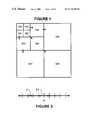
- FIG. 1is an illustration of a subband decomposition of an image
- FIG. 2is a flowchart of a method of generating a layered embedded bitstream in accordance with the present invention
- FIG. 3is an illustration of deadzone quantizer thresholds for quantization
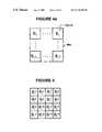
- FIG. 4 ais an illustration of block partitioning of a subband
- FIG. 4is an illustration of sub-block partitioning of a subband block
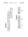
- FIG. 5is an illustration of a block bitstream
- FIG. 6is an illustration of neighbors involved in context formation for a Zero Coding operation
- FIG. 7is an illustration of a single-layer bitstream
- FIG. 8is an illustration of a first type of multi-layer bitstream
- FIG. 9is an illustration of a second type of multi-layer bitstream
- FIG. 10is an illustration of the organization of a four level tag tree built from an array of leaf nodes
- FIG. 11is a flowchart of a method of reconstructing an image from the layered embedded bitstream
- FIG. 12is a block diagram of a system for generating a layered embedded bitstream and reconstructing an image from the layered bitstream;
- FIG. 13is a flowchart of an exemplary transaction performed by the system of FIG. 12;
- FIG. 14is an illustration of an apparatus in accordance with the present invention.
- FIG. 15is a block diagram of an exemplary transform engine for the apparatus of FIG. 14.
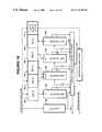
- FIG. 16is a block diagram of an exemplary block coding engine for the apparatus of FIG. 14 .
- the present inventionis embodied in methods and apparatus for compressing data into embedded bitstreams and reconstructing the data from the embedded bitstreams.
- the embedded bitstreamsare generated and processed with greater scalability, random access, error resilience and coding efficiency. Complexity is low and bit rate is controlled efficiently.
- the present inventionsupports region-of-Interest (“ROI”) reconstruction, and it can be used to provide better support for client-server applications and greater flexibility for proprietary encoders to optimize the bitstream by exploiting “psycho-visual” properties.
- ROIregion-of-Interest
- a Wavelets transformmay be used to perform the subband decomposition.
- image datae.g., luminance or chrominance data of an image
- high pass and low pass filtersin both horizontal and vertical directions, and then each of the resulting bands is subsampled by a factor of two in the horizontal and vertical directions.
- Resulting at the first levelare the following subbands: a high-pass horizontal, high-pass vertical subband; a high-pass horizontal, low-pass vertical subband; a low-pass horizontal, high-pass vertical subband; and a low-pass horizontal, low-pass vertical subband.
- Each subbandis one-quarter the size of the original image.
- Each additional decompositionis performed on the coarsest or lowest subband.
- a second decompositionwould be performed on the low-pass horizontal, low-pass vertical subband.
- Three levels of decompositionare performed to produce the three-level subband decomposition shown in FIG. 1 .
- the number of levels of decompositionwill depend upon factors such as image size.
- the coarsest frequency informationmay be found in the lowest frequency subband, which is located in the upper left corner (subband SB 0 ) of the subband decomposition.
- the finest frequency informationmay be found in the highest frequency subband, which is located in lower right corner (subband SB 9 ) of the subband decomposition.
- Each subband SB 0 to SB 9 of the subband decompositionincludes an array of transform coefficients. There is also the usual parent-child relationship among Wavelet transform coefficients.
- each subbandis partitioned into a plurality of blocks (step 102 ); blocks of HL subbands are transposed (step 104 ), and the blocks of each subband are coded (steps 106 to 112 ).
- the blocks of each subbandare coded independently of each other, that is, without using any information from the other blocks.
- the coding stepsproduce an individual block bitstream for each block.
- distortion rate datais being accumulated for each block (step 114 ).
- the distortion rate datamay be used later to determine candidate truncation points for each block bitstream.
- the block bitstreamsare concatenated into a layered embedded bitstream (step 116 ) and a bitstream syntax is added (step 118 ).
- Each layermay correspond to a discrete bit rate, an image resolution or some other unit of organization.
- each subbandis partitioned into a plurality of blocks. All blocks within a subband have the same size (e.g., 64 ⁇ 64 samples, 32 ⁇ 32 samples, 64 ⁇ 16 samples, 128 ⁇ 8 samples, where the smaller dimension is the block height), with the possible exception of blocks lying on image boundaries (i.e. the boundaries of the array of samples from the relevant subband which represent the image). Apart from this exception, the block size is also identical for all subbands, so that blocks in lower resolution subbands span a larger region in the original image. The block partitioning may start at the top-left hand corner of the subband so that only those blocks which touch the lower and right hand image boundaries may have smaller size.
- FIG. 4 aAn exemplary partitioning of a subband (e.g., SB 4 ) into L ⁇ L blocks is shown in FIG. 4 a .
- a sample sequence s[m,n], indices m and nrefer to the row and column within the block.
- blocks of HL subbandsmay be transposed prior to encoding. This allows the same algorithm is used for coding the blocks in each of the subbands.
- the LL subbandappears only in the lowest resolution level and contains DC sample values.
- the LH subbandcorresponds to horizontal low-pass filtering and vertical high-pass filtering; it responds most strongly to horizontally oriented edges and lines in the original image.
- the HL subbandcorresponds to vertical low-pass filtering and horizontal high-pass filtering; it responds most strongly to vertically oriented edges and lines in the original image.
- the HH subbandcorresponds to high-pass filtering in both the horizontal and vertical directions; it responds most strongly to diagonally oriented lines, but generally has much less impact on overall compression efficiency than either the LH or HL bands.
- transform coefficients of the blocksare quantized. Quantization may be performed such that a constant base quantization is used. A dead-zone quantizer having a central quantization interval twice as large as all other intervals may be employed. Moreover, neither the quantization step size nor the representation levels used during dequantization need be based upon properties of the specific image being compressed.
- Abs( ⁇ )represents the absolute value operator
- FIG. 3depicts the thresholds for such a dead-zone quantizer. It would be desirable to represent the quantized magnitudes v[m,n] as integers with a fixed number of bits P. Both the encoding and decoding should agree on a suitable value of P.
- the value Pmay be determined as follows.
- the magnitude values v[m,n]are represented using exactly P bits, where P is the smallest integer which satisfies 2 P ⁇ 4v max .
- the value Pmay turn out to be larger than the bit-depth of the words used to represent quantized sample values in any particular implementation.
- one or more least significant bitsmay be dropped from the quantized sample values either at the encoding or decoding or both. Since the coding is fundamentally bit-plane coding, this process of dropping least significant bits is entirely natural if the encoding and decoding implementations support representations with different maximum bit depths.
- bit-plane codingis to send first the most significant bits v p ⁇ 1 [m,n] for all samples in the code block, then the next most significant bits and so on until all bit planes have been sent. It the bitstream is truncated then some or all of the samples in the block may be missing one or more least significant bits, which is equivalent to having used a coarser dead-zone quantizer for the relevant samples, with a step size of ⁇ 2 p , where p is the index of the last available bit-plane.
- the quantized transform coefficientsare ordered by decomposing the blocks into sub-blocks, and identifying the blocks and sub-blocks having significant and insignificant coefficients. This may be done by performing a multi-level quad tree decomposition on each block.
- Each blockdenoted by B i , may be partitioned into a number of sub-blocks B i j .
- a typical maximum dimension for each sub-blockcould be sixteen samples. All sub-blocks may have the same dimension, except those at the lower and right hand boundaries of the code block, which may have smaller dimensions.
- a block of 64 ⁇ 64 samplesmay be partitioned into a 4 ⁇ 4 array of 16 ⁇ 16 sub-blocks, except for those blocks lying on the lower and right-hand image boundaries.
- a boundary block which measures 36 ⁇ 56could be partitioned into a 3 ⁇ 4 array of sub-blocks.
- Sub-blocksare formed to avoid running the zero coding algorithm (described below) on large regions of zeros, since this is relatively inefficient until the adaptive arithmetic coding has had an opportunity to learn the probability with which insignificant symbols become significant in any given bit-plane. For each bit-plane, information concerning sub-blocks that contain one or more significant samples is encoded first; all other sub-blocks are by-passed in the remaining coding phases for that bit-plane.
- quad-tree coderoffers a simple implementation.
- the use of a partial embedded quad-treeis a natural extension of the use of a single bit to represent whether or not each leading quantization layer (or bit-plane) contains any significant samples at all. It turns out to be helpful when working with independent blocks, since context information is not carried from previous blocks. Otherwise, this information would be re-learned every time.
- the embedded quad-tree codingcan be understood as sending a standard quad-tree code for the binary sequence ⁇ P (B i j ) except that all symbols which can be determined directly from a previous bit-plane ⁇ P+1 ,(B i j ) is skipped.
- Q i 1 [j]denote the sequence of level-1 quads (i.e., 2 ⁇ 2 blocks of sub-blocks).
- Q i 1 [1]consists of the top left 2 ⁇ 2 block of sub-blocks B i 1 , B i 2 , B i 5 and B i 6 (see FIG. 4 ).
- the quadsare arranged in scan-line order as are the sub-blocks.
- Level-1 quads lying on the block boundariesmight contain anywhere from one to four sub-blocks, depending upon the dimensions.
- level-2 quads Q i 2 [j]are defined to be 2 ⁇ 2 groupings of level-1 quads and so on.
- a level-2 quad tree decomposition of a 64 ⁇ 64 blockwould produce 16 ⁇ 16 sub-blocks.
- ⁇ p (Q i 1 [j])denote the significance of the level-1 quad Q i 1 [j] in bit-plane p, which is 1 if and only if at least one member sub-block is significant in bit-plane p.
- the quad-tree codervisits the level-L quad first, followed by the level-(L ⁇ 1) quads and so forth down to the level-1 quads.
- the quad tree coderWhen visiting a particular quad Q i 1 [j], the quad tree coder sends the significance of each of the four (possibly less at boundaries) child quads ⁇ p (Q i 1 ⁇ 1 [j]), or sub-blocks ⁇ P (B i j ), as appropriate, except if the significance value can otherwise be deduced upon decoding.
- the significancemay be deduced by a quad tree decoder if one or more of the following conditions is satisfied:
- This quad-tree coding algorithmis incomplete unless the significance of the “root” quad, i.e., ⁇ p (Q i 1 [1]) is also encoded. This is essentially equivalent to encoding the bit-plane p i max in which the first sample in the code block becomes significant. Either this information may be made a part of the block's own embedded bitstream, or the information can be included into the bitstream syntax.
- each blockis coded bit-plane by bit-plane, with each bit-plane being coded in multiple passes.
- Sub-blocks containing significant coefficients with respect to a previous bit-planeare coded on all but a final pass, and sub-blocks containing significant information with respect to a current bit-plane are coded on the final pass, the significant information having been identified by the quad tree decomposition.
- bit-plane pFor each bit-plane, the coding proceeds in a number of distinct passes. The number of passes may be adjusted. However, four passes will be described herein. Information encoded in each of these four different types of coding passes for bit-plane p will be denoted by p 1 , p 2 , p 3 and p 4 . The quad-tree information encoded in bit-plane p is denoted by Q p .
- FIG. 5illustrates the composition and organization of an individual block bitstream using this notation.
- the quad-tree code which identifies the significant blocks for bit-plane pappears immediately before the final coding pass for that bit-plane, but after the first three coding passes for that bit-plane. Within any given coding pass, all sub-blocks that have not yet been found to be significant are ignored. Consequently, a fourth coding pass p 4 skips over all sub-blocks which are insignificant in the current bit-plane p, whereas the first three coding passes p 1 , p 2 and p 3 skip over all sub-blocks which are insignificant in the previous bit-plane p+1, even though some of those sub-blocks might contain significant samples in the current bit-plane p.
- each coding passthe samples within each significant sub-block are coded together before moving to the next sub-block.
- Context informationis shared between the sub-blocks. Such sharing tends to reduce the complexity of both hardware and software implementations of the block coding algorithm.
- the ideais to visit each potentially significant sample in exactly one of the four coding passes associated with each bit-plane, p. To assist in the definition and implementation of these coding passes, it is helpful to introduce a “visited” state variable F[m,n], which is initialized to 0 at the end of the fourth coding pass p 4 and is set to 1 whenever the relevant sample is visited in some coding pass.
- the first coding pass p 1may be a “Forward Significance Propagation” pass; the second coding pass p 2 may be a “Backward Significance Propagation” coding pass; the third coding pass p 3 may be a “Magnitude Refinement” pass; and the fourth coding pass p 4 may be a “Normalization” pass.
- ZCZero Coding
- RLCRun-Length Coding
- SCSign Coding
- MRMagnitude Refinement
- the sub-blocksmay be visited in forward scan-line order (i.e. B i 2 , B i 2 , B i 3 , . . . ), skipping over all sub-blocks that have not yet been found significant with respect to the previous bit-plane p+1 (as identified by the quad-tree code).
- the samplesmay be visited in scan-line order, starting from the top left corner of the sub-block and finishing at the bottom right corner, skipping over all samples except those which are insignificant and have a so-called “preferred neighborhood”.
- a sample s[m,n]is said to have a preferred neighborhood if at least one of its horizontal neighbors is significant (i.e. if ⁇ [m,n ⁇ 1]+ ⁇ [m,n+1] ⁇ 0).
- a sample s[m,n]is said to have a preferred neighborhood if at least one of its diagonal neighbors is significant (i.e. ⁇ [m ⁇ 1,n ⁇ 1]+ ⁇ [m ⁇ 1,n+1]+ ⁇ [m+1,n ⁇ 1]+ ⁇ [m+1,n+1] ⁇ 0). Any neighbor which lies beyond the code block boundaries may be interpreted as insignificant.
- the Backward Significance Propagation coding passis identical to the Forward Significance Propagation coding pass except in that: 1) the sub-blocks and samples thereof are visited in reverse scan-line order, starting from the bottom right corner and ending at the top left; 2) samples s[m,n] for which the visited state variable F[m,n] is set to 1 are skipped; and 3) instead of a “preferred neighborhood”, any sample is considered for which at least one of the eight immediate neighbors is significant.
- this coding passis called the Backward Significance Propagation pass because samples which have been found to be significant serve as seeds for waves of new significance determination which propagate from right to left and from the bottom to the top of the code block.
- sub-blocksare visited in forward scan-line order, as in the Forward Significance Propagation pass, skipping over all sub-blocks which have not yet been found to be significant with respect to the previous bit-plane p+1 (as identified by the quad-tree code).
- sub-blocksare visited in forward scan-line order, as in the Forward and Backward Significance Propagation pass, skipping over all sub-blocks which have not yet been found to be significant in the current bit-plane p (as identified by the quad-tree code).
- This passis called the Normalization pass because it brings all samples in the code block up-to-date with bit-plane, p.
- Table 1provides a context assignment map for Zero Coding, which identifies the relationship between the ten context states and the four quantities, h, v, d and f, for each different type of subband.
- the context assignment map identified in Table 1has been designed for efficient implementation in hardware with a relatively small number of logic gates. In software implementations, however, the context assignment maps may be implemented via two 9-bit lookup tables instead.
- the Run-Lenght Coding operationis used in conjunction with the Zero Coding operation to reduce the average number of binary symbols that are encoded using the arithmetic coding engine.
- the RLC operationis invoked in place of the ZC operation if and only if the following conditions hold:
- Conditions (c) and (d)are enforced mainly to ensure efficient implementations of the symbol grouping scheme in both software and hardware.
- the Sign Coding operationis used at most once for each sample in the block immediately a previously insignificant symbol that is found to be significant during a Zero Coding or Run-Length Coding operation.
- two quantities, h and vare defined by:
- zero codingthe significance of any sample which lies outside the block boundaries is defined to be zero, i.e. insignificant.
- the binary symbol which is encodedis ⁇ circumflex over ( ⁇ ) ⁇ X[m,n], where ⁇ denotes the “exclusive OR” operator and the mapping from h and v to the context state index and ⁇ circumflex over ( ⁇ ) ⁇ is found from Table 2.
- This context mapshould be trivial to implement in hardware with the aid of a few gates.
- a small lookup tablemay be used to efficiently compute the context state and sign predictor.
- ⁇ [m,n]1.
- the binary symbol v p [m,n]is coded.
- a total of three magnitude refinement contextsmay be used, depending upon the sample's neighborhood, and whether or not this is the first bit-plane in which magnitude refinement is being applied.
- a second state variable ⁇ haeck over ( ⁇ ) ⁇ [m,n]identifies whether or not the Magnitude Refinement operation has already been applied to the sample in a previous bit-plane. This new state variable is initialized to zero and is set to 1 as the last step before the magnitude refinement operation is completed.
- the Magnitude Refinement contextdepends upon the value of ⁇ haeck over ( ⁇ ) ⁇ [m,n] and also upon whether or not any of the immediate horizontal and vertical neighbors are significant. Let h and v have exactly the same definition as that described for the Zero Coding operation. Then, the context assignment map is given by Table 3.
- the state variablesrepresent two of the five bits which must be maintained internally for each sample in the block. The other three bits are the sign bit X[m,n], the current bit position v p [m,n] and the visiting state variable F[m,n].
- n iis a truncation point for the block B i .
- MSEMean Squared Error
- Weighted MSEe.g. visually weighted MSE
- Additivityalso holds if the quantization errors for individual sample values are uncorrelated, regardless of whether or not the transform is orthogonal. In practice, the transform is usually only approximately orthogonal and the quantization errors are not completely uncorrelated, so even squared error metrics are only approximately additive.
- the candidate truncation points representing each code blockcorrespond to the conclusion of each coding pass.
- the number of bytes R i n for representing all coded symbols up to each truncation point n, as well as the distortion D i n incurred by truncating the bitstream at each point n,is assessed.
- n iis a truncation point for the block B i .
- MSEMean Squared Error
- Weighted MSEe.g. visually weighted MSE
- Additivityalso holds if the quantization errors for individual sample values are uncorrelated, regardless of whether or not the transform is orthogonal.
- the transformis usually only approximately orthogonal and the quantization errors are not completely uncorrelated, so even squared error metrics are only approximately additive, but this is usually good enough for us.
- the constrained optimization problem of finding the set of n i values which minimizes D subject to the constraint R ⁇ R maxmay be solved by the method of Lagrange multipliers. Specifically, the problem is equivalent to minimizing ⁇ i ⁇ ( R i n i + ⁇ ⁇ ⁇ D i n i ) ( 1 )
- Equation (1)there is a separate optimization problem for each individual code block. Specifically, for each block B i , a truncation point n i is found which minimizes (R i n + ⁇ D i n ). A “Convex Hull” algorithm may be used to search for a set of truncation points that minimizes equation (1).
- R i nmay be computed as follows.
- the block coding algorithmis responsible for reporting the number of bytes R i n for representing all symbols up to the end of the last coding pass included before each truncation point n.
- a single arithmetic code wordmay be used for the entire bitstream produced by any given block B i . This means that the exact number of bits from the code word for representing a given leading subset of the symbols which have been coding generally depends upon the symbols that follow.
- v′[m,n]holds the normalized difference between the magnitude of sample s[m,n] and the largest quantization threshold in the previous bit-plane which was not larger than the magnitude.
- the quantizercan supply fractional bits for the sample s[m,n] and hence v[m,n], which can be used in the equation above to produce accurate estimates of the distortion associated with coding passes in the less significant bit-planes.
- the reduction in distortion incurred during a single coding passmay be computed by summing the outputs of one of two different functions f s ( ⁇ ) or f m ( ⁇ ) as appropriate, whenever a sample becomes significant or its magnitude is refined and then scaling the result at the end of the coding pass by a constant value which may be computed from the bit-plane index and the value of ⁇ i 2 .
- the argument v′[m,n] to these functionshas a binary representation of the form v.xxxxx, where v, the only bit before the binary point, is simply the value of magnitude bit p, i.e. v p [m,n].
- the block bitstreamsare arranged into a layered embedded bitstream.
- the layered bitstreammay be generated by determining the extent to which each block bitstream should be truncated in order to achieve a particular target bit-rate, distortion bound or other quality metric; and composing the final compressed bitstream by stringing the blocks together in any pre-defined order, together with syntax for identifying the number of bytes that represent each block.
- the syntaxwill be described below.
- the bitstream syntaxpermits any collection of blocks to be randomly accessed and decoded. Consequently, any bitstream layer may be partially decoded, either because it is only partially received (e.g. bitstream truncation) or because limited computational capabilities upon decompression.
- Each layermay correspond to a discrete bit rate.
- bitstreamswhich are optimized for decompression at a single bit-rate, at a small collection of well-defined bit-rates (targeted scalability) or at any arbitrary bit-rate (generic scalability).
- a subbandis divided into 128 blocks. As each block is being coded, distortion statistics are being accumulated for each block. When coding has been completed, there are 128 bitstreams, each corresponding to a block.
- the 128 bitstreamsare concatenated into a layered bitstream having three layers.
- the first layercorresponds to a bit rate of 0.25 bits per pixel
- the second layercorresponds to a bit rate of 0.5 bits per pixel
- the third layercorresponds to a bit rate of 1.0 bits per pixel.
- the first truncation pointscorresponds to a bit rate of 0.25 bits per pixel
- the second truncation pointcorresponds to a bit rate of 0.5 bits per pixel
- the third truncation pointcorresponds to a bit rate of 1.0 bits per pixel.
- That portion starting at the first bit and ending at the first truncation pointis added to the first layer
- that portion starting at first truncation point and ending at the second truncation pointis added to the second layer
- that portion starting at the second truncation point and ending at the third truncation pointis added to the third layer. That portion of the bitstream following the third truncation point is discarded.
- the layersmay correspond to different levels of image resolution.
- the individual bitstreamswould be ordered according to image resolution.
- a rich bitstream syntaxis added to the layered bitstream.
- the syntaxspecifies one or more profile features that may be supported by the layered bitstream.
- the profile featuresmay include the following:
- RANDOM_ACCESSfor independently decoding a subset of the bitstream in order to reconstruct smaller regions of the image
- SNR_PROGRESSIVEfor decoding only the first N bytes of the bitstream, where N is a user specified value over which the algorithm has no control;
- RESOLUTION_PROGRESSIVEfor organizing the bitstream so as to include all information relevant to lower resolution levels before information from higher resolution levels, so that truncation of the bitstream corresponds to reduction in the resolution of the reconstructed image
- RESOLUTION_PARSABLEfor parsing the bitstream in order to extract a subset which represents a lower resolution image, for each of the resolution levels offered by the wavelet transform
- COMPONENT_PARSABLEfor parsing the bitstream in order to extract a subset which contains a smaller number of components (e.g., color components, alpha channels, any arbitrarily defined and dimensioned image component).
- bitstream syntaxcan identify the size and nature of incremental contributions from individual code blocks.
- the bitstream syntaxmay include a common header, after which each coding algorithm is free to structure the remainder of the bitstream in any desired manner, so long as the resulting organization is able to satisfy the requested set of feature profiles.
- the common headermay include the following tags: a tag indicating the total number of bytes in the header; a tag identifying the number of resolution levels in the Wavelet transform that was originally used to compress the image; a tag identifying the number of resolution levels for which information is available in the bitstream, which may be smaller than the original number of resolution levels if the bitstream has been scaled to a lower image resolution (the same number of resolution levels may be used for each image component, when compressing color or other multi-component imagery, regardless of variations in the dimensions of the different components); a tag identifying the filter set used (e.g., Daubechies 9/7 filters); a tag identifying the feature profile or profiles supported by the bitstream; a tag identifying the maximum number of bit-planes that were able to be represented in the representation of quantized subband
- tags identifying the number of rows and columns in the DC subband or the relevant image componenttags identifying whether the image component decomposed by each successively higher resolution level had even or odd height and even or odd width; and a tag identifying the base quantization step size for the relevant image component.
- the embedded block coding algorithmmay insert a few tags identifying the block and sub-block dimensions, as well as the number of bitstream layers which can be expected to appear (unless the file turns out to be truncated).
- Each layer component C ⁇ l,ccommences with a “tag block”, which is followed immediately by the code bytes associated with every code block represented by the layer component.
- the tag blockidentifies the code blocks from each subband in the relevant resolution level which are included in the layer component. It also identifies the truncation points for each included code block, from which the decoder can determine the set of coding passes for which information is available.
- Other information represented by the tag blockincludes the number of code bytes which are being sent for each included code block and the maximum bit-depth p i max for each code block which is being included for the first time (i.e. each block which was not included in any previous bitstream layer).
- the layer componentsappear in order of increasing resolution, as illustrated in FIG. 7 .
- Such a bitstreampossesses the RANDOM_ACCESS, RESOLUTION_PARSABLE and RESOLUTION_PROGRESSIVE features.
- all bitstreams constructed using the layered component syntaxpossess the RANDOM_ACCESS and RESOLUTION_PARSABLE features, at a minimum.
- a separate layer componentappears for each image component, within any given resolution level.
- the layer components associated with the different image (color) componentsappear together in each resolution level, in order of increasing component number.
- a typical color imagehas three image components and C ⁇ l,1 , C ⁇ l,2 and C ⁇ l,3 that all appear together, for each l and ⁇ . Because separate layer components are maintained for each image component, all bitstreams necessarily satisfy the requirements of the COMPONENT_PARSABLE profile feature.
- bitstream layersmay be provided. For some applications, only limited SNR scalability is requested in the sense that it might be desirable to truncate the bitstream to one of a number of well-defined bit-rates, but nothing else. In this case, a separate bitstream layer can be set aside for each distinct target bit-rate and the contents of that layer may be optimized by using the rate-distortion optimization algorithm outlined above.
- the first organizationillustrated in FIG. 8, is suitable for generating bitstreams with the RESOLUTION_PROGRESSIVE feature; of course, such a bitstream is also SNR scalable.
- the second organization, illustrated in FIG. 9,is suitable for generating bitstreams with the SNR_PROGRESSIVE feature.
- the block tagsare structured according to a “tag tree” structure.
- the tag treeis a particular type of tree structure which provides the framework for efficiently representing tag block information which exhibits significant redundancy between the different blocks of a subband and between different bitstream layers.
- the same tag tree structurewill be used for representing different types of information within tag blocks, so the following will describe tag trees in a general setting.
- the values associated with each nodeneed not be binary-valued.
- the information in a tag treemay be coded in any order.
- the coding process for a tag treeis driven from the leaves rather than the root. The idea is that information for the different leaves in the tree might be accessed in an arbitrary sequence. Specifically, in any given bitstream layer, the tree structure might be used to encode the values associated with a small subset of the leaf nodes (which corresponds to code blocks). In a later bitstream layer, the values associated with additional leaf nodes (code blocks) might be coded. Despite this arbitrary ordering, inter-block redundancy should be exploited as efficiently as possible, without resorting to more complex techniques such as conditional entropy coding.
- q 1 [m,n]denote a two-dimensional array of quantities to be represented via the tag tree. These quantities are associated with the leaf nodes of the tree (there will be one node for each code block in a given subband) so that the two-dimensional array q 1 [m,n] corresponds to the array of code blocks which partition the relevant subband. The values themselves are all non-negative integers.
- q 2 [m,n]denote the nodes at the next level of the quad-tree structure. Each of these nodes is associated with a 2 ⁇ 2 block of leaf nodes, except at the boundaries of the original array.
- smaller and smaller arrays q 3 [m,n], q 4 [m,n], . . .are defined at higher levels in the tag tree until a root level is reached, which consists of a single node q K [m,n].
- the quantity associated with each non-leaf nodeis the minimum of all descendant nodes, i.e.
- Each node in the tag treemaintains a separate state variable, which shall be denoted t k [m,n], whose interpretation is that sufficient information has already been encoded to identify whether or not q k [m,n] ⁇ t k [m,n].
- This state variableis initialized to zero for all nodes, before any information is coded.
- the tag tree coding algorithmis driven from the leaves. The algorithm may be summed up as a procedure T[m,n,t], where m and n identify the row and column indices of the leaf node for which information is requested and t identifies a threshold. The procedure sends the sufficient information to identify whether or not q 1 [m,n] ⁇ t.
- the algorithm invoked by this procedureis as follows:
- This algorithmmay be summarized as follows: start at the root node sending the minimal amount of information to identify whether or not q k [0,0]>t, if this fact is not already known; then move down the tree toward the leaf node of interest, updating the node to reflect any information which can be deduced from what is known about the parent (i.e. the value must be no smaller than t min ) and repeating the process for that node. It can and frequently does happen that this procedure sends no bits at all, which is expected if the tag tree is indeed able to exploit redundancy between leaf nodes.
- This procedure T[m,n,t]may be invoked many times in constructing the tag block for any particular bitstream layer component.
- the layer component C ⁇ l,crepresents new information from the code blocks of the subbands in resolution level l, from image component c, which is introduced in bitstream layer ⁇ .
- the componentcommences with a tag block, which includes a sequence of code bits identifying which code blocks are included from each subband, along with additional information concerning the maximum bit-depth, truncation point, and number of code bytes being sent for each included code block.
- the tag blockis followed immediately by the relevant code bytes for each of the code blocks being included.
- the code bytes for the LL, HL, LH and HH subbandsappear in that order, with the blocks of each subband appearing in scan-line order.
- the first bit in a tag blockis reserved to enable bitstream parsers to discard layer components from an existing bitstream with a minimum overhead.
- the remainder of the tag blockis divided into separate sections corresponding to the LL band (only for resolution level 1), the HL band, the LH band and the HH band, in that order.
- Each sectionis further divided into two passes.
- In the first passall blocks are scanned through in the relevant subband in scan-line order sending information to identify: 1) whether or not the code block is included in bitstream layer ⁇ ; 2) the maximum bit-depth for any code block which is being included in the bitstream for the first time; and 3) the new truncation point for the code block's embedded bitstream.
- all blocksare scanned through again in the subband in scan-line order, sending information to identify the number of code bytes which will be sent for each code block which is being included.
- Inclusion Informationis generated as follows.
- a separate tag treeis utilized for each subband to, efficiently represent the bitstream layer in which a code block is included for the first time.
- the bitstream layer indicesrun from 1 to A so that code blocks which are included in the first bitstream layer will be assigned the minimum leaf quantity of 0.
- the Inclusion Informationis represented in one of two different ways, depending upon whether or not the block has been included in a previous bitstream layer. If the block has already been included in a previous layer (i.e. ⁇ [m,n] ⁇ ), a single bit is sent to identify whether or not any new information for the code block is included in the current layer. If the bitstream has not yet been included in any previous bitstream layer, the tag tree coding procedure T[m,n, ⁇ ] is invoked. This operation emits any bits required to identify whether or not q 1 [m,n] ⁇ (i.e. whether or not ⁇ [m,n]> ⁇ ).
- bitstream layers ⁇are passed through, one at a time.
- the Maximum-Bit Depth Informationidentifies the most significant bit-plane p max [m,n] with respect to which any sample in the code block is significant.
- the code blockis identified by its row and column index within the subband.
- the maximum value which can be assumed by p max [m,n]is P ⁇ 1, where P is the number of bits used to represent the relevant quantized magnitudes.
- a second tag treeis utilized to efficiently represent p max [m,n] via the number of missing most significant bit-planes (i.e. P ⁇ 1 ⁇ p max [m,n]).
- the Truncation Point Informationidentifies the new truncation point which applies to the code block's bitstream.
- n i mindenote the minimum value which this new truncation point can take on. If the code block has already been included in a previous bitstream layer n i min is simply one more than the previous truncation point. If this is the first time the code block is being included in the bitstream, n i min might simply be 1, i.e. the first non-trivial truncation point. In many cases, however, it will be larger, because the maximum bit-depth p i max induces a minimum truncation point.
- the first truncation pointis placed immediately after the fourth coding pass P ⁇ 1 4 , where P is the number of bits used to represent the quantized magnitude values.
- the first non-empty coding passis P i max 4 . It follows that for code blocks which are being included in the bitstream for the first time, the minimum truncation point is given by
- n i min1+4(( P ⁇ 1) ⁇ P i max )
- Code size informationidentifies the number of bytes that are being sent for each code block included in the layer component. This information is sent in the second pass of the tag block section associated with the relevant subband, as explained above.
- the ⁇ i bit word representing ⁇ R iis inserted into the tag block with the most significant bit of the word appearing first.
- ⁇ ⁇is identified at the beginning of the pass, before sending the ⁇ R i values, using a comma code, whose interpretation is now explained.
- decompression and decompressionare highly symmetric. Therefore, decompression or image reconstruction can be performed essentially by reversing the steps used for compression.
- the syntaxis read and the layered bitstream is parsed to access selected layers and selected portions of block bitstreams (step 202 ).
- portions of block bitstreams corresponding to desired bit rates, desired resolutions, and desired regions of an imagecan be accessed randomly.
- a desired bit ratecan be obtained, for example, by concatenating portions of block bitstreams over successive layers.
- Those portions of the block bitstreams that have been accessed from the layered bitstreamare then decoded over multiple passes (block 204 ). Essentially, the multi-pass coding operations are reversed to produce quantized transform coefficients.
- Quad tree decodingis then performed on the quantized transform coefficients (block 206 ). Here too, the quad tree coding operations are reversed.
- Transform coefficientsare then reconstructed from the quantized transform coefficients (block 208 ).
- the middle of each uncertainty intervalmay be used as the reconstruction values.
- An inverse transformis applied to the reconstructed transform coefficients (block 210 ). Resulting is a reconstructed image, which may be displayed via a display device such as a video monitor or a printer (block 212 ).
- FIG. 12shows a system 500 including a server 502 and a client 504 that communicate over a network 506 .
- the network 506could be anything from a local area network to the Internet.
- the server 502includes a processor 508 and memory 510 .
- Stored in server memory 510is a subband decomposition 512 of an image.
- the subband decomposition 512includes a low resolution subband and a plurality of higher resolution subbands.
- Each subbandis coded as a plurality of blocks, with each block representing a region of the image. Different resolutions of the regions are represented in different subband blocks.
- the server memory 510is further encoded with a program 514 that instructs the server processor 508 to place the low resolution subband on the network 506 in response to a network request for the image.
- the server program 514further instructs the server processor 508 to place at least one additional block on the network 506 in response to a network request for a region of the image.
- the additional block or blocksprovide a higher resolution of the requested region.
- the client 504includes a second processor 516 and memory 518 for storing a program 520 .
- the client program 520instructs the client processor 516 to send network requests for images and regions of the image.
- the network requestsmay be generated interactively by a user.
- the client program 520further instructs the client processor 516 to receive blocks sent by the server 502 in response to the network requests, and reconstruct an image and region-of-interest from the blocks received on the network 506 .
- FIG. 12shows a client 504 that reconstructs images entirely via software.
- the client 504may include a chip and off-chip memory for reconstructing the image and regions of interest.
- FIG. 13shows an exemplary transaction between the server 502 and the client 504 in which the client 504 requests information about a region of a country.
- Running on the client 504is a program such a web browser. A user enters a URL of a map of the country, and the client 504 places a request for the map on the network 506 (block 602 ).
- the server 502which stores a subband decomposition of the map, receives the network request, accesses blocks in a low subband of the decomposition, and sends all of the low subband blocks to the client 504 (block 604 ).
- the client 504receives the blocks and reconstructs a low resolution image of the entire map (block 606 ).
- the low resolution mapis displayed to the user.
- an input devicesuch as a mouse
- the requestis sent to the server 502 (block 608 ).
- the server 502receives the request and accesses blocks corresponding to the region-of-interest. The blocks are taken across different subbands. The server 502 sends these higher subband blocks to the client 504 (block 610 ).
- the client 504receives the blocks and reconstructs the region-of-interest
- the region-of-interestis displayed to the user.
- the resolution of the reconstructed regiondepends upon the subbands that are accessed by the server 502 .
- This client-server applicationcan involve a large compressed image that resides on a remotely located server and that is accessed and reconstructed interactively by an individual client interested in a smaller region of the image.
- the serveronly sends those higher resolution code blocks that are relevant to the region of interest.
- the region of support of the subband synthesis filtersshould be taken into account in determining the set of subband samples which are covered by the blocks that are sent to the client.
- Blocks at lower resolution levelsmay span a substantial portion of the image so that more information is transmitted than the client has actually been requested. This is done to ensure that the region of interest is correctly reconstructed.
- an interactive userwill be able to pan across a larger region of the image over time, so that the amount of new information which is transmitted during such operations will be roughly commensurate with the size of the region which is ultimately covered, provided that previously received code blocks are properly cached and reused.
- Each block of each subbandcan be transmitted progressively so that available network bandwidth can be utilized to progressively improve the quality of a region of interest. This will depend upon the amount of time the interactive user spends on that region before panning to a new region of interest. This is a particularly attractive feature for interactive browsing of large images over the internet where most consumers have very low bandwidth links and limited patience.
- Another client-server application of block codinginvolves selectively refining regions of a large image based on an accumulated history of client requests (the server 502 could perform this step at block 610 of FIG. 13 ).
- the server 502could perform this step at block 610 of FIG. 13 .
- more ratecan be allocated to the blocks corresponding to those regions of the image most often requested in the past, with the hope that the interactive user is primarily interested in these regions.
- the regions of interestwill thus have been transmitted at a higher quality level in anticipation of the client's preference.
- the bitstreams corresponding to less frequently requested blocks of imagescan be truncated to free up space.
- the system 500can provide “degree-of-interest” decoding.
- the server 502might send some blocks with greater fidelity than others; in an interactive setting, the server 502 might continually send higher fidelity updates for the current region-of-interest until the user moves to a different region of interest.
- Included in the concept of “degree-of-interest”is resolution-of-interest.
- File formatssuch as “FlashPix” and the XIFF standard support resolution-of-interest by maintaining independent tiled versions of the same image at a variety of different resolutions.
- the multi-resolution property of the Wavelet transformmay be exploited to eliminate these multiple copies of the same image; however, the amount of distortion which can be tolerated in any given subband depends strongly upon the resolution of the image it will be used to reconstruct. Consequently, to achieve resolution-of-interest access with a single compressed image, an embedded representation of each subband is provided.
- FIG. 12illustrates a software implementation of the compression and decompression. That is, the compression and decompression are performed by general purpose computers, which are programmed to compress an image into the embedded bitstream and reconstruct the image from the embedded bitstream.
- FIG. 14illustrates a basic hardware implementation of a compression system 30 .
- the compression system 300includes an ASIC 302 or some other physically distinct device and an external memory store 304 (e.g., DRAM). There is also a destination or source for the layered bitstream 306 or its constituent code words.
- the ASIC 302includes a transform engine 308 which can carry out one level of the Wavelet decomposition, taking in image samples from an external memory store and producing subband samples for each of the LL, LH, HL and HH subbands.
- the transform engine 308writes the LL subband samples back out to the external memory store 304 , so that the same transform engine 308 can later be applied to these LL subband samples to generate another level in the decomposition.
- a generalized line-based transformmay be implemented: instead of waiting until the entire image has been passed through the first level of decomposition before exercising the transform engine 308 to generate another level, the transform engine 308 scans across the image from left to right, reading in 2K+7 lines of the image and generating K lines of each subband, after which the 2K+7 line input window is advanced by 2K lines and the process is repeated.
- the region of support for these K lines of each subbandis confined to 2K+7 input lines, since a 9/7 Debauchies Wavelet transform uses filters having nine and seven taps for the low and high pass subbands, respectively.
- the transform engineis applied to that band to generate K lines from each subband in the next resolution level, and so on.
- the external memory storeis responsible for maintaining a window of 2K+7 lines in the original image and at each intermediate resolution level in the Wavelet decomposition tree.
- the length of linesis halved for each additional level in the Wavelet decomposition tree.
- the transform engine 308reads 2K+7 lines from external memory, and writes back K lines of the LL band, each of which has half as many samples as the input image. In this way, the engine processes 2K input lines. Every second time it does this, the transform engine 308 is invoked again to form subbands in the next lower resolution level, whose lines are half as long, so the number of sample transactions for the next level is one quarter as large.
- the subband samplesare written back to the external memory store 304 as they are generated.
- a block coding engine 310codes an entire row of blocks. This allows the storage is can be recycled.
- this buffering of subband code blocks in external memory 304makes the largest impact on external memory bandwidth.
- Kthe value of K is so large that the transform engine 308 actually produces entire code blocks incrementally as it moves across the image from left to right.
- K ⁇ Hwhich allows the code blocks to be buffered up internally (e.g., in internal SRAM 312).
- the blockscould be buffered in a separate external memory which is fast and small (e.g. external SRAM).
- the transform engine 308could use Daubechies 9/7 bi-orthogonal filters.
- Wavelet transformis assumed to have an infinite number of resolution levels, with the typical Mallat decomposition, five or six resolution levels are used.
- Image samplesare assumed to arrive from the application (compression) or are consumed by the application (decompression) one line at a time, starting from the top of the image and working toward the bottom.
- the original image samplesare assumed to have 8-bit precision, while all subband samples and intermediate subband results (e.g. the intermediate LL bands in the decomposition) are maintained with 16-bit precision, including the sign bit.
- the sub-blockmay be set to 16 ⁇ 16.
- FIG. 15illustrates an exemplary implementation of the Wavelet transform engine 308 .
- the transform engine 308reads each of 2K+7 input lines, four samples at a time, storing the samples in one of three internal memory banks 402 .
- the three banks 402may be rotated to ensure that two of the (2K+7) ⁇ 4 memory banks always hold a full set of eight samples for each of the 2K+7 input lines, while the next four samples for each line are being read in.
- the input region of support for generating these four output samplesis actually only eleven input samples.
- the four output samplesare buffered in four separate 9-sample shift registers 406 , which provide an output of the transform engine 308 .
- FIG. 16provides an illustration of an exemplary implementation of the block coding engine 310 .
- the illustrationis intended to give a flavor of the types of functional blocks and interactions which might be involved in a real implementation.
- the various coding passeshave access to at most one magnitude bit-plane and the sign bit-plane.
- the code block samplesmay be stored in bit-plane order, rather than sample order at the output of the transform engine 308 .
- the block coding algorithmis defined in terms of three state bits for every sample: ⁇ [m,n], ⁇ haeck over ( ⁇ ) ⁇ [m,n] and F[n,m].
- Various shift registersmaintain moving windows into a particular sub-block; the windows each span the width of the sub-block and advance either from the top to the bottom or vice versa, depending upon the particular coding pass being considered.
- Shift registers 420 to 438are used to simplify the implementation of a moving sample window which shifts from left to right or vice versa, depending upon the particular coding pass being considered. In this way, the only signals brought out of the shift registers are those which define the relevant state information in the neighborhood of a given sample. The size of the neighborhood is different for different types of information, which is reflected in the different shift register sizes. When a sample becomes significant, its sign bits are accessed within a 3 ⁇ 3 neighborhood (which explains why the sign-bit shift register is large enough to hold three rows of the sub-block with one additional sign bit beyond the left and right boundaries of the sub-block).
- contextsare formed (via block 442 ) from a 3 ⁇ 5 neighborhood of significance state bits, which explains why the significance state shift register is large enough to hold three rows of the sub-block with two additional significance bits beyond the left and right boundaries of the sub-block.
- the examples for the coding operationsare based on the following.
- the state of the shift registersis to be re-initialized on sub-block boundaries. For a sub-block containing 16 rows, a total of 18 rows of significance state bits and 18 rows of sign bits are read, whenever this information is needed during a coding pass.
- the state bits, sign-bits and magnitude bitsare all packed into individually addressable bytes with a scan-line ordering within the block.
- a single 16 ⁇ 16 sub-blockis processed by transferring the following information into the relevant shift registers: a) all 256 magnitude bits v p [m,n]; b) 18 rows of (16+2) sign bits X[m,n]; and c) 18 rows of (16+4) significance bits ⁇ [m,n].
- the visited state bits F[m,n]are reset to zero at the beginning of this pass and so need not be read in.
- the following updated state informationis written back out of the shift registers: a) all 256 significance bits ⁇ [m,n]; and b) all 256 visited state bits F[m,n].
- the Backward Significance Propagation passis virtually identical to the Forward Significance Propagation pass, except that the visited state information F[m,n] is also be read from the internal memory 312 .
- a single 16 ⁇ 16 sub-blockis processed by transferring the following information into the relevant shift registers: a) all 256 magnitude bits v p [m,n]; b) 18 rows of (16+2) significance bits ⁇ [m,n]; c) all 256 “previously refined” state bits 6[m,n]; and d) all 256 visited state bits F[m,n].
- the updated “previously refined” state bits ⁇ haeck over ( ⁇ ) ⁇ [m,n]are written back out of the relevant shift register. Note that this is the only coding pass which accesses ⁇ haeck over ( ⁇ ) ⁇ [m,n] and that it does not require access to the sign bits; consequently, the shift register which normally maintains sign bits can be reused for this purpose.
- a single 16 ⁇ 16 sub-blockis processed by transferring the following information into the relevant shift registers: a) all 256 magnitude bits v p [m,n]; b) 18 rows of (16+2) sign bits X[m,n]; c) 18 rows of (16+4) significance bits ⁇ [m,n]; and d) all 256 visited state bits F[m,n].
- the updated significance state bits, ⁇ [m,n]are written back out of the relevant shift register.
- the distortion estimationmay be implemented with the aid of a small logic circuit 444 or two very small lookup tables.
- the coding engine 310may also incorporate a module for computing the minimum number of bits required to decode any leading subset of the symbols.
- the quad tree coding enginerepresented by block 440 , has a negligible impact on complexity.
- the quad tree coding engine 440finishes at the sub-block level, which leaves a total of only twenty nodes, even when working with code blocks of 64 ⁇ 64 samples.
- the quad tree coding engine 440may be trivially implemented by maintaining two state bits with each node: one to represent whether or not the node was significant in a previous bit-plane; and one to represent whether or not the node is significant in the current bit-plane.
- the state informationcan be updated as each new bit-plane sample v p [m,n] is written into the internal memory 312 , or at a variety of other points. Separate memory accesses are not performed by the quad-tree coding engine.
- an inventionthat compresses data into an embedded bitstream and reconstructs the data from the embedded bitstream with greater scalability, random access, error resilience, bit rate control and coding efficiency.
- Scalabilityis better because the encoder constructs bitstreams that are optimized for decompression at a single bit-rate, at a small collection of well-defined bit rates (i.e., targeted scalability) or at any arbitrary bit-rate (i.e., generic scalability).
- fractional bit-planescreates a more finely spaced set of available bit-rates and distortion values, and hence improves the performance of the post-compression rate-distortion optimization algorithm.
- the encoder and decoder according to the present inventionalso have low complexity and low memory requirements.
- the distortion estimationdoes not add substantial complexity to the implementation of compression.
- Quantizationis simple. Unlike encoders that scale a quantization step parameter in order to achieve some desired bit-rate, the encoder according to the present invention may use a constant base quantization step size for all images and all bit-rates. Moreover, any discrepancy between this base step size and an exact power of two can be absorbed into the Wavelet filter coefficients, so that the quantization operation is essentially eliminated.
- Independent block codingprovides very strong support for error resilience. Code bytes associated with each embedded bitstream may be assigned progressively lower priority; however, in the event that some of these bytes are lost or corrupted, the effect does not propagate beyond the boundary of the block. It is therefore possible to realize the benefits of prioritized significance as well as bounded influence to concoct a potent defense against transmission errors.
- the independent block coding and syntaxprovides the ability to selectively decompress particular regions of the image and thereby support region-of-interest decoding.
- the inventiondoes not produce poor compression and significant visible artifacts that have been known to occur in region-of-interest decoding in which the original image is divided into tiles and the tiles are independently compressed.
- the inventionprovides better support for client-server applications, and greater flexibility for proprietary encoders to optimize the bitstream by exploiting “psycho-visual” properties without making any changes to the decoder or bitstream syntax.
- the present inventionis not limited to the applications described above.
- the inventioncould be applied to satellite imagery. It may be used by any application that is compatible with the emerging JPEG-2000 compression standard.
- SNR scalabilityare, of course, not limited to rate control; other important applications include progressive transmission, efficient distribution of images of heterogeneous networks, and error resilient image transmission.
- the inventionis not limited to the specific embodiments described and illustrated above. Although the invention has been described in connection with subbands produced by a Wavelet transform, there is no a priori restriction to wavelet transforms or to any particular decomposition, such as the most common Mallat decomposition or other decompositions, such as “SPACL” and “PACKET”.
- the inventionis not limited to any type of entropy encoding.
- the inventionis not limited to any type of arithmetic ZC, RLC, SC and MR coding operations for each coding pass of a bit-plane.
Landscapes
- Engineering & Computer Science (AREA)
- Multimedia (AREA)
- Signal Processing (AREA)
- Compression Or Coding Systems Of Tv Signals (AREA)
Abstract
Description
| TABLE I | |
| LL, LH and HL | |
| subbands | HH subband |
| H | V | D | F | Context | D | h + v | f | Context | |
| 2 | X | X | X | 9 | ≧3 | X | x | 9 | |
| 1 | ≧1 | X | X | 8 | 2 | ≧1 | x | 8 | |
| 1 | 0 | ≧1 | X | 7 | 2 | 0 | x | 7 | |
| 1 | 0 | 0 | X | 6 | 1 | ≧2 | x | 6 | |
| 0 | 2 | X | X | 5 | 1 | 1 | x | 5 | |
| 0 | 1 | X | 4 | 1 | 0 | x | 4 | ||
| 0 | 0 | ≧2 | 3 | 0 | ≧2 | x | 3 | ||
| 0 | 0 | 1 | 2 | 0 | 1 | x | 2 | ||
| 0 | 0 | 0 | ≧1 | 1 | 0 | 0 | ≧1 | 1 | |
| 0 | 0 | 0 | 0 | 0 | 0 | 0 | 0 | 0 | |
| TABLE 2 | |||||
| H | v | {circumflex over (χ)} | |||
| 1 | 1 | 0 | 4 | ||
| 1 | 0 | 0 | 3 | ||
| 1 | −1 | 0 | 2 | ||
| 0 | 1 | 0 | 1 | ||
| 0 | 0 | 0 | 0 | ||
| 0 | −1 | 1 | 1 | ||
| −1 | 1 | −1 | 2 | ||
| −1 | 0 | −1 | 3 | ||
| −1 | −1 | −1 | 4 | ||
| TABLE 3 | ||
| {haeck over (σ)}[m, n] | h + v | Context |
| 1 | 2 | |
| 0 | ≧1 | 1 |
| 0 | 0 | 0 |


Claims (32)
Priority Applications (1)
| Application Number | Priority Date | Filing Date | Title |
|---|---|---|---|
| US09/267,248US6778709B1 (en) | 1999-03-12 | 1999-03-12 | Embedded block coding with optimized truncation |
Applications Claiming Priority (1)
| Application Number | Priority Date | Filing Date | Title |
|---|---|---|---|
| US09/267,248US6778709B1 (en) | 1999-03-12 | 1999-03-12 | Embedded block coding with optimized truncation |
Publications (1)
| Publication Number | Publication Date |
|---|---|
| US6778709B1true US6778709B1 (en) | 2004-08-17 |
Family
ID=32849428
Family Applications (1)
| Application Number | Title | Priority Date | Filing Date |
|---|---|---|---|
| US09/267,248Expired - LifetimeUS6778709B1 (en) | 1999-03-12 | 1999-03-12 | Embedded block coding with optimized truncation |
Country Status (1)
| Country | Link |
|---|---|
| US (1) | US6778709B1 (en) |
Cited By (90)
| Publication number | Priority date | Publication date | Assignee | Title |
|---|---|---|---|---|
| US20020038229A1 (en)* | 2000-04-27 | 2002-03-28 | Arun Shah | Non-additive measures and metric calculation |
| US20020038297A1 (en)* | 2000-04-27 | 2002-03-28 | Arun Shah | Allocation measures and metric calculation |
| US20020044696A1 (en)* | 1999-11-24 | 2002-04-18 | Sirohey Saad A. | Region of interest high resolution reconstruction for display purposes and a novel bookmarking capability |
| US20020057843A1 (en)* | 2000-11-10 | 2002-05-16 | Akio Matsubara | Image decompression from transform coefficients |
| US20020057276A1 (en)* | 2000-10-27 | 2002-05-16 | Kinya Osa | Data processing apparatus, processor and control method |
| US20020057844A1 (en)* | 1999-11-24 | 2002-05-16 | Sirohey Saad A. | Tessellation of trurez file stream into compressible sub-blocks to enable region-specific coefficient access |
| US20020114527A1 (en)* | 2001-02-22 | 2002-08-22 | Matsushita Graphic Communication Systems, Inc | Method and apparatus for image coding |
| US20020131507A1 (en)* | 2001-03-14 | 2002-09-19 | Anita Orhand | Blockwise coding process, of MPEG type, in which a resolution is assigned to each block |
| US20030018664A1 (en)* | 2001-05-04 | 2003-01-23 | Wee Susie J. | Method and system for midstream transcoding of scalable packets in response to downstream requirements |
| US20030035478A1 (en)* | 2000-12-21 | 2003-02-20 | David Taubman | Method and apparatus for scalable compression of video |
| US20030063813A1 (en)* | 2001-04-24 | 2003-04-03 | Naoto Shiraishi | Image compression apparatus, image expansion apparatus, image forming apparatus, image compression method, image expansion method and storage medium |
| US20030108248A1 (en)* | 2001-12-11 | 2003-06-12 | Techsoft Technology Co., Ltd. | Apparatus and method for image/video compression using discrete wavelet transform |
| US20030169935A1 (en)* | 2001-12-11 | 2003-09-11 | Yutaka Sano | Image decompression apparatus and method |
| US20040004641A1 (en)* | 2002-07-02 | 2004-01-08 | Ullas Gargi | Image segmentation and warping for specialized display viewing |
| US20040122813A1 (en)* | 2000-04-17 | 2004-06-24 | Arun Shah | Analytical server including metrics engine |
| US20040146205A1 (en)* | 2002-09-30 | 2004-07-29 | Canon Kabushiki Kaisha | Digital video compression |
| US20040146209A1 (en)* | 2002-12-02 | 2004-07-29 | Yukio Kadowaki | Image processing apparatus |
| US20040252897A1 (en)* | 2003-01-31 | 2004-12-16 | Junichi Hara | Image processing apparatus and computer-readable storage medium |
| US20040264567A1 (en)* | 2000-06-21 | 2004-12-30 | Microsoft Corporation | Video coding using wavelet transform and sub-band transposition |
| US20050002547A1 (en)* | 2000-04-03 | 2005-01-06 | Torre-Bueno Jose De La | Remote interpretation of medical images |
| US20050036559A1 (en)* | 2001-11-27 | 2005-02-17 | Catherine Lamy | Signal processing method and corresponding encoding method and device |
| US20050084169A1 (en)* | 2003-09-30 | 2005-04-21 | Yukio Kadowaki | Image processing apparatus that can generate coded data applicable to progressive reproduction |
| US20050133607A1 (en)* | 2003-12-19 | 2005-06-23 | Golla Kumar S. | Sign coding and decoding |
| US20050135692A1 (en)* | 2003-12-19 | 2005-06-23 | Golla Kumar S. | Zero coding |
| US20050135683A1 (en)* | 2003-12-19 | 2005-06-23 | Golla Kumar S. | Zero length or run length coding decision |
| US20050135684A1 (en)* | 2003-12-19 | 2005-06-23 | Golla Kumar S. | Magnitude refinement coding |
| US20050141773A1 (en)* | 2003-12-26 | 2005-06-30 | Mega Chips Lsi Solutions Inc. | Compression encoder |
| US20050259880A1 (en)* | 2000-03-10 | 2005-11-24 | Takahiro Fukuhara | Block area wavelet transform picture encoding apparatus |
| US6973217B2 (en)* | 2001-02-15 | 2005-12-06 | Ricoh Co., Ltd. | Method and apparatus for sending additional sideband information in a codestream |
| US20060013476A1 (en)* | 2004-06-30 | 2006-01-19 | Xerox Corporation | 10-bit per pixel processing using 8-bit resources |
| US20060140476A1 (en)* | 2001-05-14 | 2006-06-29 | Nikon Corporation | Image compression apparatus and image compression program |
| US20060262984A1 (en)* | 2005-05-18 | 2006-11-23 | Dts Az Research, Llc | Rate control of scalably coded images |
| US20060280371A1 (en)* | 2005-06-08 | 2006-12-14 | Hiroaki Shimazaki | Video encoding device |
| US20070016414A1 (en)* | 2005-07-15 | 2007-01-18 | Microsoft Corporation | Modification of codewords in dictionary used for efficient coding of digital media spectral data |
| US20070016412A1 (en)* | 2005-07-15 | 2007-01-18 | Microsoft Corporation | Frequency segmentation to obtain bands for efficient coding of digital media |
| US20070052736A1 (en)* | 2005-09-08 | 2007-03-08 | Seiko Epson Corporation | Image display system, image display method, and image display program |
| US20070065018A1 (en)* | 2003-12-15 | 2007-03-22 | Arvind Thiagarajan | Compressing image data |
| US20070116371A1 (en)* | 2005-11-18 | 2007-05-24 | Fuji Xerox Co., Ltd. | Decoding apparatus, inverse quantization method, and computer readable medium |
| US20070165959A1 (en)* | 2004-02-23 | 2007-07-19 | Jun Takada | 2-Dimensional signal encoding/decoding method and device |
| US20070172134A1 (en)* | 2006-01-23 | 2007-07-26 | Sharp Kabushiki Kaisha | Device for controlling data storage and/or data reconstruction and method thereof |
| US20070201550A1 (en)* | 2006-01-09 | 2007-08-30 | Nokia Corporation | Method and apparatus for entropy coding in fine granularity scalable video coding |
| US20070223826A1 (en)* | 2006-03-21 | 2007-09-27 | Nokia Corporation | Fine grained scalability ordering for scalable video coding |
| AU2003248470B2 (en)* | 2002-09-30 | 2008-02-28 | Canon Kabushiki Kaisha | Digital Video Compression |
| US20080123739A1 (en)* | 2003-09-25 | 2008-05-29 | Amimon Ltd. | Wireless Transmission of High Quality Video |
| US20080275763A1 (en)* | 2007-05-03 | 2008-11-06 | Thai Tran | Monetization of Digital Content Contributions |
| US20080279463A1 (en)* | 2007-05-08 | 2008-11-13 | Sho Son | Image processing apparatus, image processing circuit, and image processing method |
| US20080319739A1 (en)* | 2007-06-22 | 2008-12-25 | Microsoft Corporation | Low complexity decoder for complex transform coding of multi-channel sound |
| US20090006103A1 (en)* | 2007-06-29 | 2009-01-01 | Microsoft Corporation | Bitstream syntax for multi-process audio decoding |
| US20090080531A1 (en)* | 2007-09-20 | 2009-03-26 | Canon Kabushiki Kaisha | Image encoding apparatus, image decoding apparatus, and control method therefor |
| US20090161751A1 (en)* | 2007-12-19 | 2009-06-25 | Eugeniy Belyaev | Video compression and transmission system with transmitter side memory restriction |
| US20090196517A1 (en)* | 2006-08-25 | 2009-08-06 | Oscar Divorra Escoda | Method and apparatus for reduced resolution partitioning |
| EP2094016A1 (en)* | 2008-02-19 | 2009-08-26 | Thomson Licensing | Method and device for compressing an image and storage medium carrying an image compressed by said method |
| US7761290B2 (en) | 2007-06-15 | 2010-07-20 | Microsoft Corporation | Flexible frequency and time partitioning in perceptual transform coding of audio |
| US20100310188A1 (en)* | 2009-06-05 | 2010-12-09 | Thomas Richter | Encoding methods and apparatus including buffer rate control |
| US20110032995A1 (en)* | 2008-04-30 | 2011-02-10 | Panasonic Corporation | Video encoding and decoding device |
| US20110050959A1 (en)* | 2009-09-02 | 2011-03-03 | Sony Corporation | Vector embedded graphics coding |
| US20110058737A1 (en)* | 2009-09-09 | 2011-03-10 | Sony Corporation | Bitstream syntax for graphics-mode compression in wireless hd 1.1 |
| US7912324B2 (en) | 2005-04-28 | 2011-03-22 | Ricoh Company, Ltd. | Orderly structured document code transferring method using character and non-character mask blocks |
| US20110069861A1 (en)* | 2001-10-16 | 2011-03-24 | Brundage Trent J | Distributed Decoding of Digitally Encoded Media Signals |
| US20110085058A1 (en)* | 2009-10-14 | 2011-04-14 | Sony Corporation | Joint scalar embedded graphics coding for color images |
| US20110150330A1 (en)* | 2009-12-16 | 2011-06-23 | Jannard James H | Resolution Based Formatting of Compressed Image Data |
| US8249883B2 (en) | 2007-10-26 | 2012-08-21 | Microsoft Corporation | Channel extension coding for multi-channel source |
| US8340449B1 (en) | 2007-05-09 | 2012-12-25 | Google Inc. | Three-dimensional wavelet based video fingerprinting |
| US8358357B2 (en) | 2007-04-11 | 2013-01-22 | Red.Com, Inc. | Video camera |
| US20130058418A1 (en)* | 2010-05-12 | 2013-03-07 | Thomson Licensing | Methods and Apparatus for Unified Significance Map Coding |
| US20130195352A1 (en)* | 2011-08-04 | 2013-08-01 | Jorn Nystad | Methods of and apparatus for encoding and decoding data in data processing systems |
| US8554569B2 (en) | 2001-12-14 | 2013-10-08 | Microsoft Corporation | Quality improvement techniques in an audio encoder |
| US8645127B2 (en) | 2004-01-23 | 2014-02-04 | Microsoft Corporation | Efficient coding of digital media spectral data using wide-sense perceptual similarity |
| RU2509436C1 (en)* | 2009-10-30 | 2014-03-10 | Самсунг Электроникс Ко., Лтд. | Method and apparatus for encoding and decoding coding unit of picture boundary |
| US8878952B2 (en) | 2007-04-11 | 2014-11-04 | Red.Com, Inc. | Video camera |
| US20150256830A1 (en)* | 2009-08-14 | 2015-09-10 | Samsung Electronics Co., Ltd. | Video encoding method and apparatus and video decoding method and apparatus, based on hierarchical coded block pattern information |
| US9135674B1 (en) | 2007-06-19 | 2015-09-15 | Google Inc. | Endpoint based video fingerprinting |
| DE102014225820A1 (en)* | 2014-12-15 | 2015-12-03 | Deutsches Zentrum für Luft- und Raumfahrt e.V. | Method and device for image data compression of image data of an optical sensor |
| US9336367B2 (en) | 2006-11-03 | 2016-05-10 | Google Inc. | Site directed management of audio components of uploaded video files |
| US9521384B2 (en) | 2013-02-14 | 2016-12-13 | Red.Com, Inc. | Green average subtraction in image data |
| US20180084284A1 (en)* | 2016-09-22 | 2018-03-22 | Canon Kabushiki Kaisha | Method, apparatus and system for encoding and decoding video data |
| US20180176570A1 (en)* | 2016-12-15 | 2018-06-21 | WaveOne Inc. | Deep learning based on image encoding and decoding |
| EP3343921A1 (en) | 2016-12-30 | 2018-07-04 | intoPIX | Method and device for digital data compression with sign bit removal |
| US10061637B1 (en)* | 2017-01-19 | 2018-08-28 | Amdocs Development Limited | System, method, and computer program for automatic root cause analysis |
| US20190222845A1 (en)* | 2016-05-23 | 2019-07-18 | David Scott Taubman | Method and apparatus for image compression |
| US20190306375A1 (en)* | 2016-07-08 | 2019-10-03 | Hewlett-Packard Development Company, L.P. | Color table compression |
| US10460512B2 (en)* | 2017-11-07 | 2019-10-29 | Microsoft Technology Licensing, Llc | 3D skeletonization using truncated epipolar lines |
| EP2347591B1 (en) | 2008-10-03 | 2020-04-08 | Velos Media International Limited | Video coding with large macroblocks |
| US10674043B2 (en) | 2016-07-08 | 2020-06-02 | Hewlett-Packard Development Company, L.P. | Color table compression |
| US20200258264A1 (en)* | 2019-02-12 | 2020-08-13 | Arm Limited | Data processing systems |
| US11023152B2 (en) | 2019-07-12 | 2021-06-01 | Arm Limited | Methods and apparatus for storing data in memory in data processing systems |
| US11503294B2 (en) | 2017-07-05 | 2022-11-15 | Red.Com, Llc | Video image data processing in electronic devices |
| US11595692B2 (en)* | 2018-10-12 | 2023-02-28 | Kakadu R & D Pty Ltd | Block coding apparatus method and apparatus for image compression |
| US20230107110A1 (en)* | 2017-04-10 | 2023-04-06 | Eys3D Microelectronics, Co. | Depth processing system and operational method thereof |
| US12020401B2 (en) | 2018-11-07 | 2024-06-25 | Arm Limited | Data processing systems |
Citations (20)
| Publication number | Priority date | Publication date | Assignee | Title |
|---|---|---|---|---|
| US5276525A (en)* | 1991-03-22 | 1994-01-04 | Bell Communications Research, Inc. | Two-dimensional block scanning for subband image and video coding |
| US5321776A (en)* | 1992-02-26 | 1994-06-14 | General Electric Company | Data compression system including successive approximation quantizer |
| US5481308A (en)* | 1992-02-07 | 1996-01-02 | At&T Corp. | Method and apparatus for synthesizing subband video images |
| US5825935A (en)* | 1994-12-28 | 1998-10-20 | Pioneer Electronic Corporation | Subband coding method with wavelet transform for high efficiency video signal compression |
| US5982938A (en)* | 1997-03-31 | 1999-11-09 | Iterated Systems, Inc. | System and method for compressing data using differential coding of coefficient addresses |
| US6021224A (en)* | 1997-03-28 | 2000-02-01 | International Business Machines Corporation | Multiresolution lossless/lossy compression and storage of data for efficient processing thereof |
| US6125201A (en)* | 1997-06-25 | 2000-09-26 | Andrew Michael Zador | Method, apparatus and system for compressing data |
| US6141453A (en)* | 1998-02-11 | 2000-10-31 | Motorola, Inc. | Method, device and digital camera for error control and region of interest localization of a wavelet based image compression system |
| US6160846A (en)* | 1995-10-25 | 2000-12-12 | Sarnoff Corporation | Apparatus and method for optimizing the rate control in a coding system |
| US6259819B1 (en)* | 1997-04-04 | 2001-07-10 | Canon Kabushiki Kaisha | Efficient method of image compression comprising a low resolution image in the bit stream |
| US6263109B1 (en)* | 1998-09-25 | 2001-07-17 | Hewlett-Packard Company | Context-based ordering and coding of transform coefficient bit-planes for embedded bitstreams |
| US6263110B1 (en)* | 1997-09-29 | 2001-07-17 | Canon Kabushiki Kaisha | Method for data compression |
| US6266450B1 (en)* | 1997-09-29 | 2001-07-24 | Canon Kabushiki Kaisha | Encoding method and apparatus |
| US6269192B1 (en)* | 1997-07-11 | 2001-07-31 | Sarnoff Corporation | Apparatus and method for multiscale zerotree entropy encoding |
| US6298167B1 (en)* | 1995-10-25 | 2001-10-02 | Sarnoff Corporation | Vector wavelet organization |
| US6314452B1 (en)* | 1999-08-31 | 2001-11-06 | Rtimage, Ltd. | System and method for transmitting a digital image over a communication network |
| US6337929B1 (en)* | 1997-09-29 | 2002-01-08 | Canon Kabushiki Kaisha | Image processing apparatus and method and storing medium |
| US6347157B2 (en)* | 1998-07-24 | 2002-02-12 | Picsurf, Inc. | System and method for encoding a video sequence using spatial and temporal transforms |
| US6381280B1 (en)* | 1997-05-30 | 2002-04-30 | Interval Research Corporation | Single chip motion wavelet zero tree codec for image and video compression |
| US6389074B1 (en)* | 1997-09-29 | 2002-05-14 | Canon Kabushiki Kaisha | Method and apparatus for digital data compression |
- 1999
- 1999-03-12USUS09/267,248patent/US6778709B1/ennot_activeExpired - Lifetime
Patent Citations (20)
| Publication number | Priority date | Publication date | Assignee | Title |
|---|---|---|---|---|
| US5276525A (en)* | 1991-03-22 | 1994-01-04 | Bell Communications Research, Inc. | Two-dimensional block scanning for subband image and video coding |
| US5481308A (en)* | 1992-02-07 | 1996-01-02 | At&T Corp. | Method and apparatus for synthesizing subband video images |
| US5321776A (en)* | 1992-02-26 | 1994-06-14 | General Electric Company | Data compression system including successive approximation quantizer |
| US5825935A (en)* | 1994-12-28 | 1998-10-20 | Pioneer Electronic Corporation | Subband coding method with wavelet transform for high efficiency video signal compression |
| US6160846A (en)* | 1995-10-25 | 2000-12-12 | Sarnoff Corporation | Apparatus and method for optimizing the rate control in a coding system |
| US6298167B1 (en)* | 1995-10-25 | 2001-10-02 | Sarnoff Corporation | Vector wavelet organization |
| US6021224A (en)* | 1997-03-28 | 2000-02-01 | International Business Machines Corporation | Multiresolution lossless/lossy compression and storage of data for efficient processing thereof |
| US5982938A (en)* | 1997-03-31 | 1999-11-09 | Iterated Systems, Inc. | System and method for compressing data using differential coding of coefficient addresses |
| US6259819B1 (en)* | 1997-04-04 | 2001-07-10 | Canon Kabushiki Kaisha | Efficient method of image compression comprising a low resolution image in the bit stream |
| US6381280B1 (en)* | 1997-05-30 | 2002-04-30 | Interval Research Corporation | Single chip motion wavelet zero tree codec for image and video compression |
| US6125201A (en)* | 1997-06-25 | 2000-09-26 | Andrew Michael Zador | Method, apparatus and system for compressing data |
| US6269192B1 (en)* | 1997-07-11 | 2001-07-31 | Sarnoff Corporation | Apparatus and method for multiscale zerotree entropy encoding |
| US6263110B1 (en)* | 1997-09-29 | 2001-07-17 | Canon Kabushiki Kaisha | Method for data compression |
| US6266450B1 (en)* | 1997-09-29 | 2001-07-24 | Canon Kabushiki Kaisha | Encoding method and apparatus |
| US6389074B1 (en)* | 1997-09-29 | 2002-05-14 | Canon Kabushiki Kaisha | Method and apparatus for digital data compression |
| US6337929B1 (en)* | 1997-09-29 | 2002-01-08 | Canon Kabushiki Kaisha | Image processing apparatus and method and storing medium |
| US6141453A (en)* | 1998-02-11 | 2000-10-31 | Motorola, Inc. | Method, device and digital camera for error control and region of interest localization of a wavelet based image compression system |
| US6347157B2 (en)* | 1998-07-24 | 2002-02-12 | Picsurf, Inc. | System and method for encoding a video sequence using spatial and temporal transforms |
| US6263109B1 (en)* | 1998-09-25 | 2001-07-17 | Hewlett-Packard Company | Context-based ordering and coding of transform coefficient bit-planes for embedded bitstreams |
| US6314452B1 (en)* | 1999-08-31 | 2001-11-06 | Rtimage, Ltd. | System and method for transmitting a digital image over a communication network |
Cited By (211)
| Publication number | Priority date | Publication date | Assignee | Title |
|---|---|---|---|---|
| US20020057844A1 (en)* | 1999-11-24 | 2002-05-16 | Sirohey Saad A. | Tessellation of trurez file stream into compressible sub-blocks to enable region-specific coefficient access |
| US7421136B2 (en)* | 1999-11-24 | 2008-09-02 | Ge Medical Systems Information Technologies Inc. | Image tessellation for region-specific coefficient access |
| US20020044696A1 (en)* | 1999-11-24 | 2002-04-18 | Sirohey Saad A. | Region of interest high resolution reconstruction for display purposes and a novel bookmarking capability |
| US20050259880A1 (en)* | 2000-03-10 | 2005-11-24 | Takahiro Fukuhara | Block area wavelet transform picture encoding apparatus |
| US7454075B2 (en)* | 2000-03-10 | 2008-11-18 | Sony Corporation | Block area wavelet transform picture encoding apparatus |
| US20090290768A1 (en)* | 2000-04-03 | 2009-11-26 | De La Torre-Bueno Jose | Remote interpretation of medical images |
| US20050002547A1 (en)* | 2000-04-03 | 2005-01-06 | Torre-Bueno Jose De La | Remote interpretation of medical images |
| US7505614B1 (en) | 2000-04-03 | 2009-03-17 | Carl Zeiss Microimaging Ais, Inc. | Remote interpretation of medical images |
| US7031953B2 (en) | 2000-04-17 | 2006-04-18 | Hyperion Solutions Corporation | Analytical server including metrics engine |
| US7890546B2 (en) | 2000-04-17 | 2011-02-15 | Hyperion Solutions Corporation | Analytical server including metrics engine |
| US20040122813A1 (en)* | 2000-04-17 | 2004-06-24 | Arun Shah | Analytical server including metrics engine |
| US7072897B2 (en)* | 2000-04-27 | 2006-07-04 | Hyperion Solutions Corporation | Non-additive measures and metric calculation |
| US7080090B2 (en) | 2000-04-27 | 2006-07-18 | Hyperion Solutions Corporation | Allocation measures and metric calculations in star schema multi-dimensional data warehouse |
| US20020038229A1 (en)* | 2000-04-27 | 2002-03-28 | Arun Shah | Non-additive measures and metric calculation |
| US20020038297A1 (en)* | 2000-04-27 | 2002-03-28 | Arun Shah | Allocation measures and metric calculation |
| US7675976B2 (en) | 2000-06-21 | 2010-03-09 | Microsoft Corporation | Video coding using wavelet transform and sub-band transposition |
| US7680190B2 (en) | 2000-06-21 | 2010-03-16 | Microsoft Corporation | Video coding system and method using 3-D discrete wavelet transform and entropy coding with motion information |
| US7680189B2 (en) | 2000-06-21 | 2010-03-16 | Microsoft Corporation | Video coding system and method using 3-D discrete wavelet transform and entropy coding with motion information |
| US20040264567A1 (en)* | 2000-06-21 | 2004-12-30 | Microsoft Corporation | Video coding using wavelet transform and sub-band transposition |
| US20050002457A1 (en)* | 2000-06-21 | 2005-01-06 | Microsoft Corporation | Video coding using bit-plane coding based on significance of neighboring samples |
| US7653134B2 (en) | 2000-06-21 | 2010-01-26 | Microsoft Corporation | Video coding using wavelet transform of pixel array formed with motion information |
| US20050008076A1 (en)* | 2000-06-21 | 2005-01-13 | Microsoft Corporation | Video coding using wavelet transform of pixel array formed with motion information |
| US7023922B1 (en)* | 2000-06-21 | 2006-04-04 | Microsoft Corporation | Video coding system and method using 3-D discrete wavelet transform and entropy coding with motion information |
| US20050074065A1 (en)* | 2000-06-21 | 2005-04-07 | Microsoft Corporation | Video coding system and method using 3-D discrete wavelet transform and entropy coding with motion information |
| US20050094731A1 (en)* | 2000-06-21 | 2005-05-05 | Microsoft Corporation | Video coding system and method using 3-D discrete wavelet transform and entropy coding with motion information |
| US6938105B2 (en)* | 2000-10-27 | 2005-08-30 | Canon Kabushiki Kaisha | Data apparatus and method having DMA circuitry to efficiently transfer multivalued bit-plane data |
| US20020057276A1 (en)* | 2000-10-27 | 2002-05-16 | Kinya Osa | Data processing apparatus, processor and control method |
| US7181077B2 (en) | 2000-11-10 | 2007-02-20 | Ricoh Company, Ltd. | Image decompression from transform coefficients |
| US6870961B2 (en)* | 2000-11-10 | 2005-03-22 | Ricoh Company, Ltd. | Image decompression from transform coefficients |
| US20020057843A1 (en)* | 2000-11-10 | 2002-05-16 | Akio Matsubara | Image decompression from transform coefficients |
| US20050175248A1 (en)* | 2000-11-10 | 2005-08-11 | Akio Matsubara | Image decompression from transform coefficients |
| US7889791B2 (en)* | 2000-12-21 | 2011-02-15 | David Taubman | Method and apparatus for scalable compression of video |
| US20030035478A1 (en)* | 2000-12-21 | 2003-02-20 | David Taubman | Method and apparatus for scalable compression of video |
| US6973217B2 (en)* | 2001-02-15 | 2005-12-06 | Ricoh Co., Ltd. | Method and apparatus for sending additional sideband information in a codestream |
| US20020114527A1 (en)* | 2001-02-22 | 2002-08-22 | Matsushita Graphic Communication Systems, Inc | Method and apparatus for image coding |
| US6980693B2 (en)* | 2001-02-22 | 2005-12-27 | Panasonic Communications Co., Ltd. | Method and apparatus for image coding |
| US20020131507A1 (en)* | 2001-03-14 | 2002-09-19 | Anita Orhand | Blockwise coding process, of MPEG type, in which a resolution is assigned to each block |
| US7280600B2 (en)* | 2001-03-14 | 2007-10-09 | Thomson Licensing | Blockwise coding process, of MPEG type, in which a resolution is assigned to each block |
| US20030063813A1 (en)* | 2001-04-24 | 2003-04-03 | Naoto Shiraishi | Image compression apparatus, image expansion apparatus, image forming apparatus, image compression method, image expansion method and storage medium |
| US6915017B2 (en)* | 2001-04-24 | 2005-07-05 | Ricoh Company, Ltd. | Image compression apparatus, image expansion apparatus, image forming apparatus, image compression method, image expansion method and storage medium |
| US20030018664A1 (en)* | 2001-05-04 | 2003-01-23 | Wee Susie J. | Method and system for midstream transcoding of scalable packets in response to downstream requirements |
| US7516243B2 (en)* | 2001-05-04 | 2009-04-07 | Hewlett-Packard Development Company, L.P. | Method and system for midstream transcoding of scalable packets in response to downstream requirements |
| US20060140476A1 (en)* | 2001-05-14 | 2006-06-29 | Nikon Corporation | Image compression apparatus and image compression program |
| US7146039B2 (en)* | 2001-05-14 | 2006-12-05 | Nikon Corporation | Image compression apparatus and image compression program |
| US8085978B2 (en)* | 2001-10-16 | 2011-12-27 | Digimarc Corporation | Distributed decoding of digitally encoded media signals |
| US20110069861A1 (en)* | 2001-10-16 | 2011-03-24 | Brundage Trent J | Distributed Decoding of Digitally Encoded Media Signals |
| US20050036559A1 (en)* | 2001-11-27 | 2005-02-17 | Catherine Lamy | Signal processing method and corresponding encoding method and device |
| US7113645B2 (en)* | 2001-12-11 | 2006-09-26 | Ricoh Company, Ltd. | Image decompression apparatus and method |
| US20030169935A1 (en)* | 2001-12-11 | 2003-09-11 | Yutaka Sano | Image decompression apparatus and method |
| US7076108B2 (en)* | 2001-12-11 | 2006-07-11 | Gen Dow Huang | Apparatus and method for image/video compression using discrete wavelet transform |
| US20030108248A1 (en)* | 2001-12-11 | 2003-06-12 | Techsoft Technology Co., Ltd. | Apparatus and method for image/video compression using discrete wavelet transform |
| US8554569B2 (en) | 2001-12-14 | 2013-10-08 | Microsoft Corporation | Quality improvement techniques in an audio encoder |
| US9443525B2 (en) | 2001-12-14 | 2016-09-13 | Microsoft Technology Licensing, Llc | Quality improvement techniques in an audio encoder |
| US8805696B2 (en) | 2001-12-14 | 2014-08-12 | Microsoft Corporation | Quality improvement techniques in an audio encoder |
| US20040004641A1 (en)* | 2002-07-02 | 2004-01-08 | Ullas Gargi | Image segmentation and warping for specialized display viewing |
| US7278117B2 (en)* | 2002-07-02 | 2007-10-02 | Hewlett-Packard Development Company, L.P. | Image segmentation and warping for specialized display viewing |
| US7308146B2 (en)* | 2002-09-30 | 2007-12-11 | Canon Kabushiki Kaisha | Digital video compression |
| AU2003248470B2 (en)* | 2002-09-30 | 2008-02-28 | Canon Kabushiki Kaisha | Digital Video Compression |
| US20040146205A1 (en)* | 2002-09-30 | 2004-07-29 | Canon Kabushiki Kaisha | Digital video compression |
| US20040146209A1 (en)* | 2002-12-02 | 2004-07-29 | Yukio Kadowaki | Image processing apparatus |
| US7474792B2 (en)* | 2002-12-02 | 2009-01-06 | Ricoh Company, Ltd. | Image processing apparatus for using distortion amount information |
| US20040252897A1 (en)* | 2003-01-31 | 2004-12-16 | Junichi Hara | Image processing apparatus and computer-readable storage medium |
| US20080123739A1 (en)* | 2003-09-25 | 2008-05-29 | Amimon Ltd. | Wireless Transmission of High Quality Video |
| US7512281B2 (en)* | 2003-09-30 | 2009-03-31 | Ricoh Company, Ltd. | Image processing apparatus that can generate coded data applicable to progressive reproduction |
| US20050084169A1 (en)* | 2003-09-30 | 2005-04-21 | Yukio Kadowaki | Image processing apparatus that can generate coded data applicable to progressive reproduction |
| US20070065018A1 (en)* | 2003-12-15 | 2007-03-22 | Arvind Thiagarajan | Compressing image data |
| US7095897B2 (en)* | 2003-12-19 | 2006-08-22 | Intel Corporation | Zero length or run length coding decision |
| US20050135683A1 (en)* | 2003-12-19 | 2005-06-23 | Golla Kumar S. | Zero length or run length coding decision |
| US20050135692A1 (en)* | 2003-12-19 | 2005-06-23 | Golla Kumar S. | Zero coding |
| US20050133607A1 (en)* | 2003-12-19 | 2005-06-23 | Golla Kumar S. | Sign coding and decoding |
| US20050135684A1 (en)* | 2003-12-19 | 2005-06-23 | Golla Kumar S. | Magnitude refinement coding |
| US7787698B2 (en)* | 2003-12-19 | 2010-08-31 | Intel Corporation | Sign coding and decoding |
| US7613352B2 (en)* | 2003-12-26 | 2009-11-03 | Mega Chips Lsi Solutions Inc. | Compression encoder |
| US20050141773A1 (en)* | 2003-12-26 | 2005-06-30 | Mega Chips Lsi Solutions Inc. | Compression encoder |
| US8645127B2 (en) | 2004-01-23 | 2014-02-04 | Microsoft Corporation | Efficient coding of digital media spectral data using wide-sense perceptual similarity |
| US8265402B2 (en) | 2004-02-23 | 2012-09-11 | Nec Corporation | 2 dimensional signal encoding/decoding method and device |
| US8031951B2 (en)* | 2004-02-23 | 2011-10-04 | Nec Corporation | 2-dimensional signal encoding/decoding method and device |
| US20070165959A1 (en)* | 2004-02-23 | 2007-07-19 | Jun Takada | 2-Dimensional signal encoding/decoding method and device |
| US7366354B2 (en)* | 2004-06-30 | 2008-04-29 | Xerox Corporation | 10-bit per pixel processing using 8-bit resources |
| US20060013476A1 (en)* | 2004-06-30 | 2006-01-19 | Xerox Corporation | 10-bit per pixel processing using 8-bit resources |
| US7912324B2 (en) | 2005-04-28 | 2011-03-22 | Ricoh Company, Ltd. | Orderly structured document code transferring method using character and non-character mask blocks |
| US20060262984A1 (en)* | 2005-05-18 | 2006-11-23 | Dts Az Research, Llc | Rate control of scalably coded images |
| US7668380B2 (en)* | 2005-05-18 | 2010-02-23 | Dts, Inc. | Rate control of scalably coded images |
| US7860160B2 (en)* | 2005-06-08 | 2010-12-28 | Panasonic Corporation | Video encoding device |
| US20060280371A1 (en)* | 2005-06-08 | 2006-12-14 | Hiroaki Shimazaki | Video encoding device |
| US20070016412A1 (en)* | 2005-07-15 | 2007-01-18 | Microsoft Corporation | Frequency segmentation to obtain bands for efficient coding of digital media |
| US20070016414A1 (en)* | 2005-07-15 | 2007-01-18 | Microsoft Corporation | Modification of codewords in dictionary used for efficient coding of digital media spectral data |
| US7562021B2 (en) | 2005-07-15 | 2009-07-14 | Microsoft Corporation | Modification of codewords in dictionary used for efficient coding of digital media spectral data |
| US7630882B2 (en) | 2005-07-15 | 2009-12-08 | Microsoft Corporation | Frequency segmentation to obtain bands for efficient coding of digital media |
| US20070052736A1 (en)* | 2005-09-08 | 2007-03-08 | Seiko Epson Corporation | Image display system, image display method, and image display program |
| US7903886B2 (en)* | 2005-09-08 | 2011-03-08 | Seiko Epson Corporation | Partial precision compression scheme for transmitting data to a display over a limited-bandwidth transmission path |
| US8005306B2 (en)* | 2005-11-18 | 2011-08-23 | Fuji Xerox Co., Ltd. | Decoding apparatus, inverse quantization method, and computer readable medium |
| US20070116371A1 (en)* | 2005-11-18 | 2007-05-24 | Fuji Xerox Co., Ltd. | Decoding apparatus, inverse quantization method, and computer readable medium |
| US20070201550A1 (en)* | 2006-01-09 | 2007-08-30 | Nokia Corporation | Method and apparatus for entropy coding in fine granularity scalable video coding |
| WO2007080486A3 (en)* | 2006-01-09 | 2007-10-18 | Nokia Corp | Method and apparatus for entropy coding in fine granularity scalable video coding |
| US20070172134A1 (en)* | 2006-01-23 | 2007-07-26 | Sharp Kabushiki Kaisha | Device for controlling data storage and/or data reconstruction and method thereof |
| US8284435B2 (en)* | 2006-01-23 | 2012-10-09 | Sharp Kabushiki Kaisha | Device for controlling data storage and/or data reconstruction and method thereof |
| WO2007107855A3 (en)* | 2006-03-21 | 2008-06-12 | Nokia Corp | Fine grained scalability ordering for scalable video coding |
| US20070223826A1 (en)* | 2006-03-21 | 2007-09-27 | Nokia Corporation | Fine grained scalability ordering for scalable video coding |
| US8363936B2 (en)* | 2006-08-25 | 2013-01-29 | Thomson Licensing | Method and apparatus for reduced resolution partitioning |
| US20090196517A1 (en)* | 2006-08-25 | 2009-08-06 | Oscar Divorra Escoda | Method and apparatus for reduced resolution partitioning |
| US9336367B2 (en) | 2006-11-03 | 2016-05-10 | Google Inc. | Site directed management of audio components of uploaded video files |
| US8878952B2 (en) | 2007-04-11 | 2014-11-04 | Red.Com, Inc. | Video camera |
| US9596385B2 (en) | 2007-04-11 | 2017-03-14 | Red.Com, Inc. | Electronic apparatus |
| US9230299B2 (en) | 2007-04-11 | 2016-01-05 | Red.Com, Inc. | Video camera |
| US9787878B2 (en) | 2007-04-11 | 2017-10-10 | Red.Com, Llc | Video camera |
| US9019393B2 (en) | 2007-04-11 | 2015-04-28 | Red.Com, Inc. | Video processing system and method |
| US9792672B2 (en) | 2007-04-11 | 2017-10-17 | Red.Com, Llc | Video capture devices and methods |
| US8872933B2 (en) | 2007-04-11 | 2014-10-28 | Red.Com, Inc. | Video camera |
| US9245314B2 (en) | 2007-04-11 | 2016-01-26 | Red.Com, Inc. | Video camera |
| US8358357B2 (en) | 2007-04-11 | 2013-01-22 | Red.Com, Inc. | Video camera |
| US9436976B2 (en) | 2007-04-11 | 2016-09-06 | Red.Com, Inc. | Video camera |
| US10643249B2 (en) | 2007-05-03 | 2020-05-05 | Google Llc | Categorizing digital content providers |
| US8924270B2 (en) | 2007-05-03 | 2014-12-30 | Google Inc. | Monetization of digital content contributions |
| US20080275763A1 (en)* | 2007-05-03 | 2008-11-06 | Thai Tran | Monetization of Digital Content Contributions |
| US20080279463A1 (en)* | 2007-05-08 | 2008-11-13 | Sho Son | Image processing apparatus, image processing circuit, and image processing method |
| US8467624B2 (en)* | 2007-05-08 | 2013-06-18 | Ricoh Company, Ltd. | Image processing apparatus, image processing circuit, and image processing method |
| US8611689B1 (en)* | 2007-05-09 | 2013-12-17 | Google Inc. | Three-dimensional wavelet based video fingerprinting |
| US8340449B1 (en) | 2007-05-09 | 2012-12-25 | Google Inc. | Three-dimensional wavelet based video fingerprinting |
| US7761290B2 (en) | 2007-06-15 | 2010-07-20 | Microsoft Corporation | Flexible frequency and time partitioning in perceptual transform coding of audio |
| US9135674B1 (en) | 2007-06-19 | 2015-09-15 | Google Inc. | Endpoint based video fingerprinting |
| US20080319739A1 (en)* | 2007-06-22 | 2008-12-25 | Microsoft Corporation | Low complexity decoder for complex transform coding of multi-channel sound |
| US8046214B2 (en) | 2007-06-22 | 2011-10-25 | Microsoft Corporation | Low complexity decoder for complex transform coding of multi-channel sound |
| US9741354B2 (en) | 2007-06-29 | 2017-08-22 | Microsoft Technology Licensing, Llc | Bitstream syntax for multi-process audio decoding |
| US8255229B2 (en) | 2007-06-29 | 2012-08-28 | Microsoft Corporation | Bitstream syntax for multi-process audio decoding |
| US9026452B2 (en) | 2007-06-29 | 2015-05-05 | Microsoft Technology Licensing, Llc | Bitstream syntax for multi-process audio decoding |
| US7885819B2 (en) | 2007-06-29 | 2011-02-08 | Microsoft Corporation | Bitstream syntax for multi-process audio decoding |
| US20090006103A1 (en)* | 2007-06-29 | 2009-01-01 | Microsoft Corporation | Bitstream syntax for multi-process audio decoding |
| US8645146B2 (en) | 2007-06-29 | 2014-02-04 | Microsoft Corporation | Bitstream syntax for multi-process audio decoding |
| US9349376B2 (en) | 2007-06-29 | 2016-05-24 | Microsoft Technology Licensing, Llc | Bitstream syntax for multi-process audio decoding |
| US8238437B2 (en)* | 2007-09-20 | 2012-08-07 | Canon Kabushiki Kaisha | Image encoding apparatus, image decoding apparatus, and control method therefor |
| US20090080531A1 (en)* | 2007-09-20 | 2009-03-26 | Canon Kabushiki Kaisha | Image encoding apparatus, image decoding apparatus, and control method therefor |
| US8249883B2 (en) | 2007-10-26 | 2012-08-21 | Microsoft Corporation | Channel extension coding for multi-channel source |
| US8126047B2 (en)* | 2007-12-19 | 2012-02-28 | Intel Corporation | Video compression and transmission system with transmitter side memory restriction |
| US20090161751A1 (en)* | 2007-12-19 | 2009-06-25 | Eugeniy Belyaev | Video compression and transmission system with transmitter side memory restriction |
| US20100310187A1 (en)* | 2008-02-19 | 2010-12-09 | Thomson Licensing | Method and device for compressing an image and storage medium carrying an image compressed by said method |
| US8478060B2 (en) | 2008-02-19 | 2013-07-02 | Thomson Licensing | Method and device for compressing an image and storage medium carrying an image compressed by said method |
| EP2094016A1 (en)* | 2008-02-19 | 2009-08-26 | Thomson Licensing | Method and device for compressing an image and storage medium carrying an image compressed by said method |
| WO2009103614A1 (en)* | 2008-02-19 | 2009-08-27 | Thomson Licensing | Method and device for compressing an image and storage medium carrying an image compressed by said method |
| US20110032995A1 (en)* | 2008-04-30 | 2011-02-10 | Panasonic Corporation | Video encoding and decoding device |
| EP2347591B2 (en)† | 2008-10-03 | 2023-04-05 | Qualcomm Incorporated | Video coding with large macroblocks |
| EP2347591B1 (en) | 2008-10-03 | 2020-04-08 | Velos Media International Limited | Video coding with large macroblocks |
| US20100310188A1 (en)* | 2009-06-05 | 2010-12-09 | Thomas Richter | Encoding methods and apparatus including buffer rate control |
| US8437565B2 (en)* | 2009-06-05 | 2013-05-07 | Accusoft Corporation | Encoding methods and apparatus including buffer rate control |
| US20150256829A1 (en)* | 2009-08-14 | 2015-09-10 | Samsung Electronics Co., Ltd. | Video encoding method and apparatus and video decoding method and apparatus, based on hierarchical coded block pattern information |
| US9467711B2 (en)* | 2009-08-14 | 2016-10-11 | Samsung Electronics Co., Ltd. | Video encoding method and apparatus and video decoding method and apparatus, based on hierarchical coded block pattern information and transformation index information |
| US20150256830A1 (en)* | 2009-08-14 | 2015-09-10 | Samsung Electronics Co., Ltd. | Video encoding method and apparatus and video decoding method and apparatus, based on hierarchical coded block pattern information |
| US20150256852A1 (en)* | 2009-08-14 | 2015-09-10 | Samsung Electronics Co., Ltd. | Video encoding method and apparatus and video decoding method and apparatus, based on hierarchical coded block pattern information |
| US9426484B2 (en)* | 2009-08-14 | 2016-08-23 | Samsung Electronics Co., Ltd. | Video encoding method and apparatus and video decoding method and apparatus, based on transformation index information |
| US20150256831A1 (en)* | 2009-08-14 | 2015-09-10 | Samsung Electronics Co., Ltd. | Video encoding method and apparatus and video decoding method and apparatus, based on hierarchical coded block pattern information |
| US9451273B2 (en)* | 2009-08-14 | 2016-09-20 | Samsung Electronics Co., Ltd. | Video encoding method and apparatus and video decoding method and apparatus, based on transformation index information |
| US9521421B2 (en)* | 2009-08-14 | 2016-12-13 | Samsung Electronics Co., Ltd. | Video decoding method based on hierarchical coded block pattern information |
| US20110050959A1 (en)* | 2009-09-02 | 2011-03-03 | Sony Corporation | Vector embedded graphics coding |
| US8447102B2 (en) | 2009-09-02 | 2013-05-21 | Sony Corporation | Vector embedded graphics coding |
| US8306322B2 (en) | 2009-09-09 | 2012-11-06 | Sony Corporation | Bitstream syntax for graphics-mode compression in wireless HD 1.1 |
| US20110058737A1 (en)* | 2009-09-09 | 2011-03-10 | Sony Corporation | Bitstream syntax for graphics-mode compression in wireless hd 1.1 |
| US20110085058A1 (en)* | 2009-10-14 | 2011-04-14 | Sony Corporation | Joint scalar embedded graphics coding for color images |
| US8355057B2 (en) | 2009-10-14 | 2013-01-15 | Sony Corporation | Joint scalar embedded graphics coding for color images |
| US9264708B2 (en) | 2009-10-30 | 2016-02-16 | Samsung Electronics Co., Ltd. | Method and apparatus for encoding and decoding coding unit of picture boundary |
| RU2509436C1 (en)* | 2009-10-30 | 2014-03-10 | Самсунг Электроникс Ко., Лтд. | Method and apparatus for encoding and decoding coding unit of picture boundary |
| US8837840B2 (en) | 2009-10-30 | 2014-09-16 | Samsung Electronics Co., Ltd. | Method and apparatus for encoding and decoding coding unit of picture boundary |
| US8842922B2 (en) | 2009-10-30 | 2014-09-23 | Samsung Electronics Co., Ltd. | Method and apparatus for encoding and decoding coding unit of picture boundary |
| RU2605360C2 (en)* | 2009-10-30 | 2016-12-20 | Самсунг Электроникс Ко., Лтд. | Method and apparatus for encoding and decoding coding unit of picture boundary |
| US8842925B2 (en) | 2009-10-30 | 2014-09-23 | Samsung Electronics Co., Ltd. | Method and apparatus for encoding and decoding coding unit of picture boundary |
| US8842926B2 (en) | 2009-10-30 | 2014-09-23 | Samsung Electronics Co., Ltd. | Method and apparatus for encoding and decoding coding unit of picture boundary |
| US20110150330A1 (en)* | 2009-12-16 | 2011-06-23 | Jannard James H | Resolution Based Formatting of Compressed Image Data |
| US8611652B2 (en)* | 2009-12-16 | 2013-12-17 | Red.Com, Inc. | Resolution based formatting of compressed image data |
| US9479749B2 (en) | 2009-12-16 | 2016-10-25 | Redcom.Com, Inc. | Resolution based formatting of compressed image data |
| US9906764B2 (en) | 2009-12-16 | 2018-02-27 | Red.Com, Llc | Resolution based formatting of compressed image data |
| US9793921B2 (en)* | 2010-05-12 | 2017-10-17 | Thomson Licensing Dtv | Methods and apparatus for unified significance map coding |
| US20130058418A1 (en)* | 2010-05-12 | 2013-03-07 | Thomson Licensing | Methods and Apparatus for Unified Significance Map Coding |
| US11177826B2 (en) | 2010-05-12 | 2021-11-16 | Interdigital Madison Patent Holdings, Sas | Methods and apparatus for unified significance map coding |
| US11309910B2 (en) | 2010-05-12 | 2022-04-19 | Interdigital Madison Patent Holdings, Sas | Methods and apparatus for unified significance map coding |
| US20240275402A1 (en)* | 2010-05-12 | 2024-08-15 | Interdigital Madison Patent Holdings, Sas | Methods and apparatus for unified significance map coding |
| US11942969B2 (en) | 2010-05-12 | 2024-03-26 | Interdigital Madison Patent Holdings, Sas | Methods and apparatus for unified significance map coding |
| US11671112B2 (en) | 2010-05-12 | 2023-06-06 | Interdigital Madison Patent Holdings, Sas | Methods and apparatus for unified significance map coding |
| US10305510B2 (en) | 2010-05-12 | 2019-05-28 | Interdigital Madison Patent Holdings | Methods and apparatus for unified significance map coding |
| US9014496B2 (en)* | 2011-08-04 | 2015-04-21 | Arm Limited | Methods of and apparatus for encoding and decoding data in data processing systems |
| US20130195352A1 (en)* | 2011-08-04 | 2013-08-01 | Jorn Nystad | Methods of and apparatus for encoding and decoding data in data processing systems |
| US9716866B2 (en) | 2013-02-14 | 2017-07-25 | Red.Com, Inc. | Green image data processing |
| US9521384B2 (en) | 2013-02-14 | 2016-12-13 | Red.Com, Inc. | Green average subtraction in image data |
| US10582168B2 (en) | 2013-02-14 | 2020-03-03 | Red.Com, Llc | Green image data processing |
| DE102014225820A1 (en)* | 2014-12-15 | 2015-12-03 | Deutsches Zentrum für Luft- und Raumfahrt e.V. | Method and device for image data compression of image data of an optical sensor |
| US20190222845A1 (en)* | 2016-05-23 | 2019-07-18 | David Scott Taubman | Method and apparatus for image compression |
| US10951897B2 (en)* | 2016-05-23 | 2021-03-16 | Kakadu R & D Pty Ltd | Method and apparatus for image compression |
| US11470322B2 (en) | 2016-05-23 | 2022-10-11 | Kakadu R & D Pty Ltd | Method and apparatus for image compression |
| US20190306375A1 (en)* | 2016-07-08 | 2019-10-03 | Hewlett-Packard Development Company, L.P. | Color table compression |
| US10602028B2 (en)* | 2016-07-08 | 2020-03-24 | Hewlett-Packard Development Company, L.P. | Color table compression |
| US10674043B2 (en) | 2016-07-08 | 2020-06-02 | Hewlett-Packard Development Company, L.P. | Color table compression |
| US10574862B2 (en) | 2016-07-08 | 2020-02-25 | Hewlett-Packard Development Company, L.P. | Printing device supply component |
| US10630868B2 (en) | 2016-07-08 | 2020-04-21 | Hewlett-Packard Development Company, L.P. | Component comprising a memory device including corrective data |
| US20180084284A1 (en)* | 2016-09-22 | 2018-03-22 | Canon Kabushiki Kaisha | Method, apparatus and system for encoding and decoding video data |
| US10666948B2 (en)* | 2016-09-22 | 2020-05-26 | Canon Kabushiki Kaisha | Method, apparatus and system for encoding and decoding video data |
| US20180176570A1 (en)* | 2016-12-15 | 2018-06-21 | WaveOne Inc. | Deep learning based on image encoding and decoding |
| US10977553B2 (en) | 2016-12-15 | 2021-04-13 | WaveOne Inc. | Enhanced coding efficiency with progressive representation |
| US11100394B2 (en) | 2016-12-15 | 2021-08-24 | WaveOne Inc. | Deep learning based adaptive arithmetic coding and codelength regularization |
| US11062211B2 (en) | 2016-12-15 | 2021-07-13 | WaveOne Inc. | Deep learning based adaptive arithmetic coding and codelength regularization |
| US11423310B2 (en) | 2016-12-15 | 2022-08-23 | WaveOne Inc. | Deep learning based adaptive arithmetic coding and codelength regularization |
| US11593632B2 (en)* | 2016-12-15 | 2023-02-28 | WaveOne Inc. | Deep learning based on image encoding and decoding |
| EP3343921A1 (en) | 2016-12-30 | 2018-07-04 | intoPIX | Method and device for digital data compression with sign bit removal |
| US10061637B1 (en)* | 2017-01-19 | 2018-08-28 | Amdocs Development Limited | System, method, and computer program for automatic root cause analysis |
| US20230107110A1 (en)* | 2017-04-10 | 2023-04-06 | Eys3D Microelectronics, Co. | Depth processing system and operational method thereof |
| US12301806B2 (en) | 2017-07-05 | 2025-05-13 | RED Digital Cinema, Inc. | Video image data processing in electronic devices |
| US11818351B2 (en) | 2017-07-05 | 2023-11-14 | Red.Com, Llc | Video image data processing in electronic devices |
| US11503294B2 (en) | 2017-07-05 | 2022-11-15 | Red.Com, Llc | Video image data processing in electronic devices |
| US10460512B2 (en)* | 2017-11-07 | 2019-10-29 | Microsoft Technology Licensing, Llc | 3D skeletonization using truncated epipolar lines |
| US11595692B2 (en)* | 2018-10-12 | 2023-02-28 | Kakadu R & D Pty Ltd | Block coding apparatus method and apparatus for image compression |
| US12020401B2 (en) | 2018-11-07 | 2024-06-25 | Arm Limited | Data processing systems |
| US11600026B2 (en)* | 2019-02-12 | 2023-03-07 | Arm Limited | Data processing systems |
| US20200258264A1 (en)* | 2019-02-12 | 2020-08-13 | Arm Limited | Data processing systems |
| US11023152B2 (en) | 2019-07-12 | 2021-06-01 | Arm Limited | Methods and apparatus for storing data in memory in data processing systems |
Similar Documents
| Publication | Publication Date | Title |
|---|---|---|
| US6778709B1 (en) | Embedded block coding with optimized truncation | |
| US6546143B1 (en) | Efficient wavelet-based compression of large images | |
| US5881176A (en) | Compression and decompression with wavelet style and binary style including quantization by device-dependent parser | |
| US5966465A (en) | Compression/decompression using reversible embedded wavelets | |
| US7321695B2 (en) | Encoder rate control | |
| US6229927B1 (en) | Reversible embedded wavelet system implementation | |
| US6757437B1 (en) | Compression/decompression using reversible embedded wavelets | |
| US7382925B2 (en) | Compression and decompression system with reversible wavelets and lossy reconstruction | |
| US7110609B2 (en) | System and method for progressively transform coding digital data | |
| US6347157B2 (en) | System and method for encoding a video sequence using spatial and temporal transforms | |
| WO1999023602A1 (en) | System and method for efficiently encoding video frame sequences | |
| JP2007267384A (en) | Compression device and compression method | |
| GB2341035A (en) | Video coding method | |
| JP3989999B2 (en) | Data compression system | |
| Jaber | Wavelet-Based Scalable Image Compression Techniques | |
| Choraś | JPEG 2000 Image Coding Standard-A Review and Applications | |
| Taubman et al. | Em0 bedded block coding in JPEG2333 | |
| JPH11225330A (en) | Digital image compressing method |
Legal Events
| Date | Code | Title | Description |
|---|---|---|---|
| AS | Assignment | Owner name:HEWLETT-PACKARD COMPANY, CALIFORNIA Free format text:ASSIGNMENT OF ASSIGNORS INTEREST;ASSIGNOR:TAUBMAN, DAVID S.;REEL/FRAME:010150/0546 Effective date:19990609 | |
| AS | Assignment | Owner name:HEWLETT-PACKARD DEVELOPMENT COMPANY L.P., TEXAS Free format text:ASSIGNMENT OF ASSIGNORS INTEREST;ASSIGNOR:HEWLETT-PACKARD COMPANY;REEL/FRAME:014061/0492 Effective date:20030926 Owner name:HEWLETT-PACKARD DEVELOPMENT COMPANY L.P.,TEXAS Free format text:ASSIGNMENT OF ASSIGNORS INTEREST;ASSIGNOR:HEWLETT-PACKARD COMPANY;REEL/FRAME:014061/0492 Effective date:20030926 | |
| STCF | Information on status: patent grant | Free format text:PATENTED CASE | |
| FPAY | Fee payment | Year of fee payment:4 | |
| REMI | Maintenance fee reminder mailed | ||
| FPAY | Fee payment | Year of fee payment:8 | |
| AS | Assignment | Owner name:DOLBY INTERNATIONAL AB, NETHERLANDS Free format text:ASSIGNMENT OF ASSIGNORS INTEREST;ASSIGNOR:HEWLETT-PACKARD DEVELOPMENT COMPANY, L.P.;REEL/FRAME:032840/0343 Effective date:20140429 | |
| FPAY | Fee payment | Year of fee payment:12 |