US6776888B2 - Biosensor - Google Patents
BiosensorDownload PDFInfo
- Publication number
- US6776888B2 US6776888B2US10/089,289US8928902AUS6776888B2US 6776888 B2US6776888 B2US 6776888B2US 8928902 AUS8928902 AUS 8928902AUS 6776888 B2US6776888 B2US 6776888B2
- Authority
- US
- United States
- Prior art keywords
- filter
- biosensor
- base plate
- sample solution
- sample
- Prior art date
- Legal status (The legal status is an assumption and is not a legal conclusion. Google has not performed a legal analysis and makes no representation as to the accuracy of the status listed.)
- Expired - Fee Related, expires
Links
Images


Classifications
- C—CHEMISTRY; METALLURGY
- C12—BIOCHEMISTRY; BEER; SPIRITS; WINE; VINEGAR; MICROBIOLOGY; ENZYMOLOGY; MUTATION OR GENETIC ENGINEERING
- C12Q—MEASURING OR TESTING PROCESSES INVOLVING ENZYMES, NUCLEIC ACIDS OR MICROORGANISMS; COMPOSITIONS OR TEST PAPERS THEREFOR; PROCESSES OF PREPARING SUCH COMPOSITIONS; CONDITION-RESPONSIVE CONTROL IN MICROBIOLOGICAL OR ENZYMOLOGICAL PROCESSES
- C12Q1/00—Measuring or testing processes involving enzymes, nucleic acids or microorganisms; Compositions therefor; Processes of preparing such compositions
- C12Q1/001—Enzyme electrodes
- C12Q1/004—Enzyme electrodes mediator-assisted
- G—PHYSICS
- G01—MEASURING; TESTING
- G01N—INVESTIGATING OR ANALYSING MATERIALS BY DETERMINING THEIR CHEMICAL OR PHYSICAL PROPERTIES
- G01N27/00—Investigating or analysing materials by the use of electric, electrochemical, or magnetic means
- G01N27/26—Investigating or analysing materials by the use of electric, electrochemical, or magnetic means by investigating electrochemical variables; by using electrolysis or electrophoresis
- G01N27/28—Electrolytic cell components
- G01N27/30—Electrodes, e.g. test electrodes; Half-cells
- G01N27/327—Biochemical electrodes, e.g. electrical or mechanical details for in vitro measurements
- G01N27/3271—Amperometric enzyme electrodes for analytes in body fluids, e.g. glucose in blood
- G01N27/3272—Test elements therefor, i.e. disposable laminated substrates with electrodes, reagent and channels
Definitions
- the present inventionrelates to a biosensor that carries out high-speed, highly-accurate, simple determination of a target object in a sample.
- a biosensorhas been proposed to determine a specific component in a sample by a simple procedure without any dilution or stirring the sample solution (Japanese Laid-Open Patent Publication No. 2-062952).
- an electrode systemincluding a measurement electrode or a working electrode, a counter electrode, and a reference electrode is formed on an insulating base plate, for example, by screen printing.
- An enzyme reaction layerincluding a hydrophilic polymer, an oxidation-reduction enzyme, and an electron mediator is then formed on the electrode system.
- a buffermay be added to this enzyme reaction layer according to the requirements.
- the biosensoris applicable to measurement of diverse substances by selecting an appropriate enzyme that reacts with a target substance of measurement as the substrate.
- an appropriate enzyme that reacts with a target substance of measurementfor example, when glucose oxidase is used as the oxidation-reduction enzyme, the biosensor is constructed to measure the concentration of glucose in blood. This is widely used as a glucose sensor.
- Application of cholesterol oxidasegives a biosensor that measures cholesterol in serum.
- the value of serum cholesterol generally used for the index of diagnosisis the sum of the concentrations of cholesterol and cholesterol ester.
- the cholesterol esteris, however, not the substrate of the oxidation reaction with cholesterol oxidase.
- an additional processis thus required to change the cholesterol ester to cholesterol.
- Cholesterol esteraseis used as the enzyme that catalyzes this process.
- the biosensor including cholesterol esterase and cholesterol oxidase in its enzyme reaction layeris used to measure the total concentration of cholesterol in serum.
- the measurement of cholesterolis affected by cholesterol that is present in the cell membrane.
- the coexistence of a surface active agent with cholesterol esterase in the reaction reagent layeris preferable to enhance the reactivity.
- the surface active agentdestroys the cell membrane in many cases, and there is a possibility that the substances inside the cell directly or indirectly affect the enzyme reaction or the electrode reaction. From this point of view, it is preferable that the enzyme reaction and the subsequent electrode reaction proceed in plasma or serum in the cholesterol sensor. In biosensors other than the cholesterol sensor, the presence of hemocytes in blood may also affect the response. It is accordingly ideal that the enzyme reaction and the electrode reaction proceed in a solution free of hemocytes.
- Centrifugationis a known method to separate plasma or serum from whole blood.
- the centrifugation methodtakes a rather long time and requires complicated operations.
- U.S. Pat. No. 3,607,092discloses a membrane used for testing blood.
- This membranehas a thin film layer that has permeability to liquids but impermeability to solids like hemocytes and giant molecules like protein. Namely this thin film functions to filter out the hemocytes.
- this thin filmfunctions to filter out the hemocytes.
- the solid componentis accumulated on the thin film with the passage of blood, a large area of the thin film layer is required to obtain filtrate of a certain amount sufficient for the reaction of the biosensor. The above-mentioned thin film is thus not sufficient.
- U.S. Pat. No. 4,477,575discloses an apparatus for and a method of separating serum from whole blood passing through a glass fiber filter.
- the method of separating serum from whole blood with a fiber or porous filteris applicable to the biosensor. This method, however, does not make the hemocytes kept in the filter but simply slows down the flow of hemocytes for separation of plasma.
- a certain quantity of filtered plasma or serum sufficient for the reaction in the biosensorshould be obtained, before the hemocytes are flown out of the filter.
- a specific setting that satisfies this conditionshould be applied for the length of the filter in the direction of blood flow.
- the filter satisfying this conditionis disposed between one portion of the biosensor with the electrode system and the reaction reagent system and another portion of the biosensor for supplying blood as a sample to construct the biosensor having the ability of filtering the hemocytes.
- FIG. 9shows a biosensor of such construction.
- FIG. 9is a decomposed perspective view of the biosensor without the reaction reagent layer.
- silver pasteis printed on an insulating base plate 101 composed of polyethylene terephthalate by screen printing to form leads 102 and 103 and the base of an electrode system.
- Conductive carbon paste including a resin binderis printed on the base plate 101 to form the electrode system including a working electrode 104 and a counter electrode 105 , while insulting paste is printed to form an insulating layer 106 .
- the working electrode 104is connected to the lead 102 , and the counter electrode 105 to the lead 103 .
- the insulating layer 106makes the exposed area of the working electrode 104 and the counter electrode 105 constant, and partly covers the leads.
- the processarranges the insulating base plate 101 with the electrode system, a cover 108 with an air vent 109 , a spacer 107 , and a filter 111 having the ability of filtering hemocytes at the positional relationship shown by the one-dot chain line and joins together to assemble a biosensor.
- the filter 111is cut to fit a sample solution supply pathway, which is defined by a slit 110 of the spacer 107 between the cover 108 and the insulating base plate 101 .
- Numeral 113 arepresents a portion at which the filter 111 is in contact with the insulating base plate.
- the filter 111is disposed between the electrode system and a sample supply unit 112 on the base plate without covering over the electrode system including the working electrode 104 and the counter electrode 105 in the sample solution supply pathway.
- the permeation rate of hemocytesis less than the permeation rate of plasma as the liquid component, and the plasma accordingly soaks out of the end of the filter close to the electrode system.
- the soak-out plasmadissolves reaction reagents, which include enzymes and are carried at a specific position covering over the electrode system or on the rear face of the cover immediately above the specific position, and fills the whole sample solution supply pathway from the vicinity of the electrode system to the air vent 109 .
- the whole sample solution supply pathwayis filled with the liquid, the flow of the liquid in the filter 111 stops, so that the hemocytes do not reach the end of the filter close to the electrode system but are retained at the current position.
- the reaction reagent layer dissolved in plasmachemically reacts with a target component included in the plasma, cholesterol in the case of the cholesterol sensor. After elapse of a preset time, the value of electric current is measured by means of the electrode reaction. This determines the component in the plasma.
- part of the blood added dropwise to the sample supply unit 112is not absorbed through the end of the filter 111 close to the sample supply unit. But the blood including hemocytes is transferred through the gap between the sample solution supply pathway and the filter 111 to reach the reaction reagent layer. This causes the hemocytes or some component in the hemocytes to react with the reaction reagent and give a significant error to the measurement.
- Bonding the filter 111 to the sample solution supply pathway via an adhesivemay prevent the transfer of blood through the gap between the filter 111 and the sample solution supply pathway.
- the adhesivemay, however, affect the blood components. This method also requires application of the adhesive on either the surface of the filter 111 or the sample solution supply pathway, which results in the complicated manufacturing process.
- the object of the present inventionis thus to solve the drawbacks discussed above by improving a biosensor with a filter that is capable of filtering a solid component like hemocytes.
- the object of the present inventionis to provide a biosensor that has stable response by allowing a sample added to the sensor to soak into a filter and making only a sample solution transmitted through the filter reach a reaction reagent layer and an electrode system.
- a biosensor in accordance with the present inventionincludes: an insulating base plate, an electrode system that is provided on the base plate and has at least a working electrode and a counter electrode, a cover member that is combined with the base plate to define a sample solution supply pathway for leading a sample solution from a sample supply unit to the electrode system, a reaction reagent system including at least an oxidation-reduction enzyme and an electron mediator, and a filter disposed between the electrode system and the sample supply unit in the sample solution supply pathway, the biosensor having a space that encircles surface of the filter in an area from one end of the filter close to the sample supply unit to the other end of the filter close to the electrode system.
- the sample supply unitis provided on the base plate, and the sample solution supply pathway is formed along the base plate and the cover member.
- the space surrounding the surface of the filterhas a width of not less than 0.5 mm.
- the width of the space less than 0.5 mmmay cause blood transmitted through a gap between the base plate and/or the cover member forming the sample solution supply pathway and the filter to reach the area of the space by means of capillarity.
- the preferable width of the spaceranges from 0.5 mm to 5.0 mm.
- the width over 5.0 mmmay undesirably lead to deformation of the filter under vibrations applied to the sensor. More specifically, the preferable width is 1.0 mm to 3.0 mm.
- the sample supply unitis provided on the cover member, and the sample solution supply pathway is disposed in a direction of gravity from the sample supply unit.
- the width of the space surrounding the surface of the filteris not less than 100 ⁇ m and is smaller than the thickness of the filter.
- the filter used hereis a porous body having spaces connecting with one another in a three-dimensional manner, and the porous body moves blood from the sample supply unit toward the sample solution supply pathway by capillarity while functions to filter hemocytes based on a difference between flow resistances of plasma and the hemocytes.
- a non-woven fabricpreferably composed of a hydrophilic fiber, such as fiber glass, cellulose, or pulp, filter paper, or another porous body may be applied for the filter.
- the arrangement of the present inventionis preferably applied for a cholesterol sensor in which the oxidation-reduction enzyme is cholesterol oxidase.
- the reaction reagent systemincludes an enzyme having an ability of hydrolyzing cholesterol ester. It is also preferable that the enzyme having the ability of hydrolyzing cholesterol ester is cholesterol esterase and that the reaction reagent system includes a surface active agent.
- cover member and the insulating base plateare transparent.
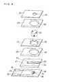
- FIG. 1is a decomposed perspective view illustrating a biosensor without a reaction reagent layer in one embodiment of the present invention.
- FIG. 2is a vertical sectional view illustrating the biosensor of FIG. 1 .
- FIG. 3is a plan view illustrating a main part of a biosensor in another embodiment of the present invention.
- FIG. 4is a vertical sectional view illustrating a biosensor in still another embodiment of the present invention.
- FIG. 5is a vertical sectional view illustrating a biosensor in another embodiment of the present invention.
- FIG. 6is a decomposed perspective view illustrating the biosensor of FIG. 5 .
- FIG. 7is a vertical sectional view illustrating a biosensor in still another embodiment of the present invention.
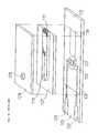
- FIG. 8is a decomposed perspective view illustrating the biosensor of FIG. 7 .
- FIG. 9is a decomposed perspective view illustrating a prior art biosensor without a reaction reagent layer.
- a biosensor of the present inventionhas a sample solution supply pathway that is defined by a combination of a base plate and a cover member, and a filter that is disposed in the sample solution supply pathway between a sample supply unit provided on either the base plate or the cover member and an electrode system on the base plate, the biosensor having a space surrounding the surface of the filter in an area from one end of the filter close to the sample supply unit to the other end of the filter close to the electrode system. Namely there is a specific area, in which the whole circumference of the surface of the filter is not in contact with either of the base plate and the cover member that form the sample solution supply pathway.
- One aspect of the present inventionis a biosensor, which includes: an insulating base plate, an electrode system that is provided on the base plate and has at least a working electrode and a counter electrode, a cover member that is combined with the base plate to define a sample solution supply pathway for leading a sample solution from a sample supply unit on the base plate to the electrode system on the base plate, a reaction reagent system that includes at least an oxidation-reduction enzyme and an electron mediator and is provided on or in the vicinity of the electrode system, and a filter disposed between the electrode system and the sample supply unit in the sample solution supply pathway, the biosensor having a space that encircles surface of the filter in an area from one end of the filter close to the sample supply unit to the other end of the filter close to the electrode system.
- a biosensorwhich includes: an insulating base plate, an electrode system that is provided on the base plate and has at least a working electrode and a counter electrode, a cover member that is combined with the base plate, a sample solution supply pathway that is formed between the cover member and the base plate for leading a sample solution from a sample supply unit on the cover member to the electrode system on the base plate, a reaction reagent system that includes at least an oxidation-reduction enzyme and an electron mediator and is provided on or in the vicinity of the electrode system, and a filter disposed between the electrode system and the sample supply unit in the sample solution supply pathway, the biosensor having a space that encircles surface of the filter in an area from one end of the filter close to the sample supply unit to the other end of the filter close to the electrode system.
- the sample solution like blood added dropwise to the sample supply unitis absorbed by the filter and flows through the sample solution supply pathway toward the electrode system and the reaction reagent layer, while the solid substance like the hemocytes is filtered out by the filter. Only the sample solution from which the solid component like the hemocytes is filtered out accordingly reaches the electrode system.
- part of the sample solutionmay not be absorbed by the filter but may directly flow from a little gap in the contact area of the filter with the sample solution supply pathway into the sample solution supply pathway. Even in such cases, the gap encircling the surface of the filter effectively prevents the sample solution from further flowing toward the electrode system. Therefore, the sample solution including the solid substance like hemocytes is prevented from flowing through the space toward the electrode system.
- the reaction reagent systemis provided on or in the vicinity of the electrode system in the sample solution supply pathway.
- a diversity of enzymesmay be used for the oxidation-reduction enzyme included in the reaction reagent system. Such examples include glucose oxidase, lactate oxidase, and cholesterol oxidase.
- cholesterol oxidase and an enzyme having an ability of hydrolyzing cholesterol esterare used.
- Cholesterol esterase and lipoprotein lipaseare examples of the enzyme having the ability of hydrolyzing cholesterol ester.
- cholesterol esteraseis preferable since it quickly changes cholesterol ester to cholesterol in the presence of an appropriate surface active agent.
- reaction reagent systemincludes the enzyme having the ability of hydrolyzing cholesterol ester
- reaction reagent systemfurther includes a surface active agent for enhancing the ability of the enzyme. This desirably shortens the time required for the enzyme reaction.
- n-octyl- ⁇ -D-thioglucosidepolyethylene glycol monododecyl ether, sodium cholate, dodecyl- ⁇ -maltoside, sucrose monolaurate, sodium deoxycholate, sodium taurodeoxycholate, N,N-bis(3-D-gluconamide propyl)cholamide, N,N-bis(3-D-gluconamide propyl)deoxycholamide, polyoxyethylene-p-t-octylphehyl ether (TritonX-100) may be used for the surface active agent for enhancing the activity of cholesterol esterase.
- TritonX-100polyoxyethylene-p-t-octylphehyl ether
- the electrode systemincludes a silver electrode composed of, for example, silver paste, and a carbon electrode obtained by covering the silver electrode with carbon paste.
- the sample solutionincludes a surface active agent
- the sample solutionsoaks into carbon particles by the function of the surface active agent. This may lower the activity of the carbon electrode. This also causes the sample solution to be in contact with the silver electrode.
- a voltageis applied to the working electrode under such conditions, an oxidation reaction may occur on the silver electrode to generate electric current and give a positive error to the observed value of electric current.
- One proposed method to suppress such phenomenacovers the surface of the electrode system with a hydrophilic polymer.
- the hydrophilic polymermakes the introduced sample solution a viscous layer, which prevents the sample solution from coming into contact with the electrodes.
- hydrophilic polymerexamples include carboxymethyl cellulose, polyvinyl pyrrolidone, polyvinyl alcohol, ethyl cellulose, hydroxypropyl cellulose, gelatin, polyacrylic acid and its salts, starch and its derivatives, polymers of maleic anhydride or its salts, polyacrylamide, methacrylate resin, and poly-2-hydroxyethyl methacrylate.
- the following methodmay be applied to suppress the effects of the surface active agent discussed above.
- a specific part of the electrode system that comes into contact with the sample solutionis made of only carbon paste. Silver paste for ensuring the electric conductivity is used only for the part covered with an insulating layer.
- the hydrophilic polymer layeris not required in such printed electrodes.
- the hydrophilic polymeralso functions to prevent protein in the sample solution or the mixture of the sample solution and the reaction reagent from being adsorbed on the surface of the electrode and lowering the activity of the electrode reaction. It is accordingly preferable to use the hydrophilic polymer even in such printed electrodes.
- an electron mediatorshould be added to the reaction reagent layer.
- Any water-soluble compound that mediates transfer of electrons between the enzyme and the electrodefor example, potassium ferricyanide, p-benzoquinone, phenazine methosulfate, and ferrocene derivatives (oxidation type) may be applied for the electron mediator.
- a two electrode system using only the working electrode and the counter electrode and a three electrode system using the reference electrode in addition to the two electrodesis applicable to measure the oxidation current.
- the three electrode systemis preferable to ensure the higher accuracy of measurement.
- FIG. 1is a decomposed perspective view illustrating a biosensor in one embodiment of the present invention
- FIG. 2is a vertical sectional view of the biosensor.
- Silver pasteis printed on an insulating base plate 1 of polyethylene terephthalate by screen printing to form leads 2 and 3 and the base of an electrode system.
- Electrically conductive carbon paste containing a resin binderis further printed on the base plate 1 to form an electrode system including a working electrode 4 and a counter electrode 5 , while insulating paste is printed to form an insulating layer 6 .
- the working electrode 4is connected to the lead 2 , and the counter electrode 5 to the lead 3 .
- the insulating layer 6makes the exposed areas of the working electrode 4 and the counter electrode 5 constant, and partly covers the leads.
- the insulating base plate 1 with the electrode system, a cover 8 with an air vent 9 , s spacer 7 , and a filter 11 having the ability of filtering hemocytesare bonded according to the positional relationship shown by the one-dot chain line, thereby to prepare a biosensor.
- a sample solution supply pathway running along the base plate 1 and the cover 8is defined by a slit 10 of the spacer 7 between the base plate 1 and the cover 8 .
- the filter 11is cut into the size fitting the sample solution supply pathway and is disposed between the electrode system and a sample supply unit not to cover the electrode system.
- Numerals 13 a and 13 brepresent parts at which the filter 11 is in contact with the insulating base plate 1 and the cover 8 , respectively.
- the filter 11There is a specific area from one end of the filter 11 close to the sample supply unit 12 to the other end close to the electrode system, in which the surface of the filter 11 is not in contact with any of the base plate 1 , the spacer 7 , and the cover 8 that define the sample solution supply pathway.
- the base plate 1 and the spacer 7respectively have through holes 14 and 15 at corresponding positions
- the cover 8has two notches 16 connecting with the slit 10 .
- Lids 17 and 18are attached to the outer faces of the base plate 1 and the cover 8 to respectively cover the through holes 14 and 15 formed in the base plate 1 and the cover 8 .
- the through holes 14 and 15 and the notches 16 , 16form the space encircling the surface of the filter 11 .
- the through holes 14 and 15can exert their functions even in the open condition, although they are closed with the lids 17 and 18 in this embodiment.
- the filter 11is exposed to outside in the open condition. There is accordingly some possibility that evaporation of the sample solution through the exposed part causes the liquid passing through the filter and reaching the electrode system to flow back.
- the lids 17 and 18are accordingly provided to cover the through holes of the base plate and the cover. In the case where both the base plate and the cover are sufficiently thick, recesses that do not require the lids 17 and 18 may be formed instead of the through holes.
- the sample solutionWhen the sample solution is added dropwise onto the sample supply unit 12 on the base plate to come into contact with an end of the filter 11 close to the sample supply unit, the sample solution soaks into the filter 11 .
- the filter 11removes the solid component like hemocytes, and the plasma flows through the sample solution supply pathway and is led into the sensor.
- the plasmafills up the whole sample solution supply pathway from the vicinity of the electrode system to the portion of the air vent 9 , while dissolving therein the reaction reagents carried at a specific position covering over the electrode system or on the rear face of the cover immediately above the specific position.
- the whole sample solution supply pathwayis filled with the liquid, the flow of the liquid in the filter 11 stops.
- the filter 11is designed to produce such a difference in flow resistance between plasma and hemocytes that the hemocytes have not yet reached the end of the filter when the plasma has passed through the filter and filled up the whole sample solution supply pathway.
- the length between one end of the sample solution supply pathway defined by the slit 10 on the sample supply unit to the outer circumference of the air vent 9is 12.5 mm.
- the slit 10has the width of 2.0 mm and the depth of 0.1 mm.
- the dimensions of the through holes 14 and 15 expressed as (dimension in the direction perpendicular to the longitudinal direction of the base plate) ⁇ (dimension in the longitudinal direction of the base plate)are 4.0 ⁇ 3.0 mm, and the dimensions of the notches 16 are also 4.0 ⁇ 3.0 mm.
- Both the base plate and the coverhave the thickness of 0.35 mm, and the thickness of the spacer is 0.1 mm.
- the filter 11is surrounded by space having a thickness of 0.35 mm above and below the filter 11 and a thickness of 2.0 mm on both right and left sides of the filter 11 , and a width of 3.0 mm in the flowing direction of the sample solution (hereinafter referred to as the width of the space).
- the spaceis located at a position 1 mm apart from the end of the sample supply unit and 3.0 mm apart from the end of the electrode system.
- the above dimensionsshow just an example of the preferred embodiment, and are not restrictive in any sense.
- FIG. 2is a vertical sectional view illustrating the assembled biosensor.
- a hydrophilic polymer layer 21 and an electron mediator layer 22 covering over the hydrophilic polymer layer 21are formed on the electrode system on the base plate 1 .
- the filter 11is disposed in the sample solution supply pathway defined by the slit 10 of the spacer 7 .
- the end of the filter 11may be or may not be in contact with the electrode system, but must not be in contact with and be apart from the working electrode 4 in the electrode system.
- a layer 23 including enzymes and a surface active agentis formed in a specific area interposed between an end of the filter 11 close to the electrode system and the air vent 9 on the rear face of the cover 8 . The contact of this layer 23 with the end of the filter 11 facilitates the flow of the sample solution into the layer 23 , although the contact is not essential.
- FIG. 3is a plan view illustrating the positional relationship between the spacer and the filter in a biosensor in another embodiment of the present invention.
- the slit 10 for defining the sample solution supply pathwayhas a portion 10 a in which the filter is fitted, and a portion 10 b that has the electrode system and receives a flow-in sample passing through the filter.
- the width of the portion 10 ais different from the width of the portion 10 b . More specifically, in the embodiment of FIG. 3, the width of the portion 10 a with the filter fitted therein is narrower than the width of the portion 10 b with the electrode system.
- FIG. 4is a vertical sectional view illustrating a biosensor in still another embodiment of the present invention.
- This biosensorhas a similar structure to that of FIG. 2 with a different arrangement of the reaction reagent layer.
- the hydrophilic polymer layer 21is formed on the electrode system.
- a porous carrier 24 impregnated with enzymes, a surface active agent, and an electron mediatoris provided on the cover 8 to be in contact with an end of the filter 11 .
- FIG. 5is a vertical sectional view illustrating a biosensor in another embodiment of the present invention
- FIG. 6is a decomposed perspective view of the biosensor without its reaction reagent layer.
- leads 32 and 33 , a working electrode 34 and a counter electrode 35 connecting with the respective leads, and an insulating layer 36are formed on an insulating base plate 31 .
- a combination of multiple spacers 41 , 43 , 45 , 47 , and 49 with a cover 52is provided on the base plate 31 .
- a filter 51is interposed between the spacer 43 and the cover 52 .
- a through hole 53 in the cover 52forms a sample supply unit.
- Through holes 42 , 44 , 46 , 48 , and 50 formed in the spacers 41 , 43 , 45 , 57 , and 49define a sample solution supply pathway running in the direction of gravity.
- the spacer 47is partly in contact with the outer circumference of the filter 51 to locate the filter 51 .
- the spacer 41has an air vent 54 that connects the end of the sample solution supply pathway to the air.
- the sample solutionis introduced in the direction of gravity by means of capillarity into the sample solution supply pathway, which connects the through hole 53 disposed above the electrode system to function as the sample supply unit to the electrode system. The movement of the sample solution stops when the plasma passing through the filter 51 reaches the electrode system.
- the thickness of the spacers 49 and 45 that specify the height of the spaces 55 and 56 surrounding the filter 51is preferably not less than 100 ⁇ m.
- the reaction of the sample solution with the reagentsproceeds in the through hole 42 formed in the spacer 41 .
- the preferable thickness of the spacer 41ranges 100 to 200 ⁇ m.
- the orientation of the sample solution supply pathway in the direction of gravityenables the sample to pass through the filter by means of the gravity and quickly reach the reaction reagent layer.
- a CMC layer 61 and an electron mediator layer 62are formed on the electrode system.
- a layer 63 including enzymes and a surface active agentis formed on the rear face of the spacer 43 .
- FIG. 7is a vertical sectional view illustrating a biosensor in another embodiment of the present invention.
- FIG. 8is a decomposed perspective view illustrating the biosensor of FIG. 7 without a reaction reagent layer.
- This sensoris practically similar to the sensor shown in FIGS. 5 and 6, except that the spacer 43 is replaced by a sample solution induction layer 57 mainly composed of non-woven fabric.
- a CMC layer 61 and a layer 64 including enzymes, a surface active agent, and an electron mediatorare provided on the electrode system.
- a cholesterol sensorwas produced as an example of the biosensors.
- the processfirst added a 0.5% by weight of aqueous solution of sodium carboxymethyl cellulose (hereinafter referred to as CMC) as the hydrophilic polymer dropwise onto the electrode system on the insulating base plate 1 shown in FIG. 1 and dried the solution in a hot blast drier at 50° C. for 10 minutes, so as to form a CMC layer 21 .
- CMCsodium carboxymethyl cellulose
- the processsubsequently added 4 ⁇ l of an aqueous solution of potassium ferricyanide (corresponding to 70 mM potassium ferricyanide) as the electron mediator dropwise on to the CMC layer and dried the solution in the hot blast drier at 50° C. for 10 minutes, so as to form a potassium ferrocyanide layer 22 .
- Triton X-100was added 2 ⁇ l of a 2% by weight of ethanol solution of Triton X-100 as the surface active agent dropwise into a recess defined by the cover 8 and the slit 10 of the spacer 7 , and dried the solution at room temperature for 3 minutes, so as to form a layer of the surface active agent.
- Triton X-100was added to an aqueous solution in which cholesterol oxidase originating from Nocardia (EC1.1.3.6, hereinafter referred to as ChOD) and cholesterol esterase originating from Pseudomonas (EC. 3.1.1.13, hereinafter referred to as ChE) were dissolved.
- ChODcholesterol oxidase originating from Nocardia
- ChEcholesterol esterase originating from Pseudomonas
- the processadded 1.5 ⁇ l of the solution mixture onto the surface active agent layer, froze the layer with liquid nitrogen, and dried it in a Kjeldahl flask overnight in a freeze drier to give an enzyme/surface active agent layer 23 including 1 unit (U)/sensor cholesterol oxidase, 2.5 U/sensor cholesterol esterase, and 2% by weight of the surface active agent.
- the processthen arranged a 2 mm ⁇ 8 mm rectangular glass filter (GC50 manufactured by ADVANTEC LTD., thickness: 0.19 mm) at the position shown in FIG. 1 not to be in contact with the working electrode.
- the through holes 14 and 15 and the notches 16 , 16were formed at the specific position with the filter of the sample solution supply pathway as shown in FIG. 1 . This defined the area in which the surface of the filter was not in contact with any of the insulating base plate, the spacer, and the cover defining the sample solution supply pathway. The dimensions of these elements are specified previously with reference to FIG. 1 .
- sample solution20 ⁇ l of a whole blood sample was added dropwise onto the sample supply unit 12 of the base plate 1 .
- Visual observationswere made through the cover 8 composed of a transparent material to confirm that the liquid passing through the filter reached the outer circumferential part of the air vent 9 in the sample solution supply pathway.
- a pulse voltage of +0.5 Vwas applied to the working electrode in the direction of the anode with the counter electrode as the reference.
- the value of electric currentwas measured after 5 seconds. The result gave a response depending upon the concentration of cholesterol in serum.
- the enzyme/surface active agent layer 23was formed by the freeze drying method in this example, although it may be formed by the air drying method. In the latter case, however, the solubility of the reaction reagent layer is significantly worsened. It accordingly takes a long time until the reaction is completed after the filtered liquid reaches the outer circumference of the air vent 9 in the sample solution supply pathway.
- the reaction reagent systemwas composed of the enzyme/surface active agent layer 23 formed by the freeze drying method on the rear face of the cover in the sample solution supply pathway and the CMC layer 21 and the potassium ferricyanide layer 22 formed by the air drying method at the specified position covering over the electrode system on the base plate.
- the reaction reagent systemwas composed of a porous carrier 24 , which was in contact with an end of the filter 11 and had enzymes, a surface active agent, and an electron mediator soaked therein and carried thereon, and the CMC layer 21 formed by the air drying method at the specified position covering over the electrode system on the base plate.
- the arrangement of making part of the reagents included in the reaction reagent system carried on the porous carrierenhances the solubility of the reaction reagents into the sample solution, as in the case of the freeze drying method.
- Example 1the process first added a 0.5% by weight of aqueous solution of CMC as the hydrophilic polymer dropwise onto the electrode system and dried the solution in a hot blast drier at 50° C. for 10 minutes, so as to form the CMC layer 21 .
- the processbonded and fixed the porous carrier 24 made of felt which was cut into the size of 2 ⁇ 4.5 mm and mainly composed of glass filters at a specified position shown in FIG. 4 on the cover in the sample solution supply pathway with a cellulose-based adhesive (Cemedine C manufactured by Cemedine Co., Ltd), so as to be in contact with an end of the filter 11 .
- a cellulose-based adhesiveCosmetic C manufactured by Cemedine Co., Ltd
- the processadded 5 ⁇ l of the aqueous solution, in which cholesterol oxidase, cholesterol esterase, potassium ferricyanide, and Triton X-100 were dissolved as in the case of Example 1, dropwise onto the porous carrier 24 , made the solution homogeneously soak into the porous carrier 24 , and dried the solution in a hot blast drier at 50° C. for 15 minutes.
- Example 2the process located the filter and joined the cover member with the base plate 1 to complete a biosensor.
- the porous carrier 24had the thickness of approximately 0.1 to 0.2 mm.
- the distance between the base plate 1 and the cover 8 in the part of the sample solution supply pathway closer to the electrode systemwas accordingly set equal to 0.3 mm, which was significantly greater than 0.1 mm in the structure of Example 1.
- GB100Rwas applied for the filter 11 .
- This biosensorshowed a response corresponding to the concentration of cholesterol at three minutes after the dropwise addition of the whole blood sample to the sample supply unit.
- the base plate 1 and the cover 8were made of a transparent material, so that the flow-in state of the sample was observable with naked eyes.
- the specific part of the slit 10 for forming the sample solution supply pathway with the filter fitted thereinhas a width equal to the width of the part that has the electrode system and receives a flow of the sample passing through the filter.
- One of these partsmay be narrower than the other.
- FIG. 5shows the positional relationship between the spacer and the filter and their shapes in such an example.
- the arrangement of the reagents constituting the reaction reagent layer and their carrying methodare not restricted to the specifications of the above examples, as long as the reagents in the reaction reagent system are quickly dissolved in the sample solution to ensure smooth progress of the enzyme reaction.
- the present inventioneffectively prevents a solid component like hemocytes included in a sample solution from coming into contact with the electrode system and the reaction reagent system and thereby provide a biosensor that ensures highly accurate measurement and has a little variation in response.
Landscapes
- Chemical & Material Sciences (AREA)
- Life Sciences & Earth Sciences (AREA)
- Health & Medical Sciences (AREA)
- Organic Chemistry (AREA)
- Wood Science & Technology (AREA)
- Molecular Biology (AREA)
- Proteomics, Peptides & Aminoacids (AREA)
- Zoology (AREA)
- Physics & Mathematics (AREA)
- Analytical Chemistry (AREA)
- Biochemistry (AREA)
- General Health & Medical Sciences (AREA)
- Biophysics (AREA)
- Immunology (AREA)
- Engineering & Computer Science (AREA)
- Electrochemistry (AREA)
- Pathology (AREA)
- Biotechnology (AREA)
- Microbiology (AREA)
- General Physics & Mathematics (AREA)
- Chemical Kinetics & Catalysis (AREA)
- Hematology (AREA)
- Bioinformatics & Cheminformatics (AREA)
- General Engineering & Computer Science (AREA)
- Genetics & Genomics (AREA)
- Investigating Or Analysing Biological Materials (AREA)
- Apparatus Associated With Microorganisms And Enzymes (AREA)
- Measuring Or Testing Involving Enzymes Or Micro-Organisms (AREA)
Abstract
Description
Claims (17)
Applications Claiming Priority (3)
| Application Number | Priority Date | Filing Date | Title |
|---|---|---|---|
| JP2000232385 | 2000-07-31 | ||
| JP2000-232385 | 2000-07-31 | ||
| PCT/JP2001/006472WO2002010735A1 (en) | 2000-07-31 | 2001-07-26 | Biosensor |
Publications (2)
| Publication Number | Publication Date |
|---|---|
| US20020148726A1 US20020148726A1 (en) | 2002-10-17 |
| US6776888B2true US6776888B2 (en) | 2004-08-17 |
Family
ID=18725079
Family Applications (1)
| Application Number | Title | Priority Date | Filing Date |
|---|---|---|---|
| US10/089,289Expired - Fee RelatedUS6776888B2 (en) | 2000-07-31 | 2001-07-26 | Biosensor |
Country Status (7)
| Country | Link |
|---|---|
| US (1) | US6776888B2 (en) |
| EP (1) | EP1223425B1 (en) |
| JP (1) | JP4184074B2 (en) |
| CN (1) | CN1180259C (en) |
| DE (1) | DE60137111D1 (en) |
| ES (1) | ES2317947T3 (en) |
| WO (1) | WO2002010735A1 (en) |
Cited By (82)
| Publication number | Priority date | Publication date | Assignee | Title |
|---|---|---|---|---|
| US20040163953A1 (en)* | 2000-10-06 | 2004-08-26 | Bhullar Raghbir S. | Biosensor |
| US20050072670A1 (en)* | 2002-03-01 | 2005-04-07 | Miwa Hasegawa | Biosensor |
| US7025774B2 (en) | 2001-06-12 | 2006-04-11 | Pelikan Technologies, Inc. | Tissue penetration device |
| US7198606B2 (en) | 2002-04-19 | 2007-04-03 | Pelikan Technologies, Inc. | Method and apparatus for a multi-use body fluid sampling device with analyte sensing |
| US7229458B2 (en) | 2002-04-19 | 2007-06-12 | Pelikan Technologies, Inc. | Method and apparatus for penetrating tissue |
| US7232451B2 (en) | 2002-04-19 | 2007-06-19 | Pelikan Technologies, Inc. | Method and apparatus for penetrating tissue |
| US7244265B2 (en) | 2002-04-19 | 2007-07-17 | Pelikan Technologies, Inc. | Method and apparatus for penetrating tissue |
| US7258693B2 (en) | 2002-04-19 | 2007-08-21 | Pelikan Technologies, Inc. | Device and method for variable speed lancet |
| US7291117B2 (en) | 2002-04-19 | 2007-11-06 | Pelikan Technologies, Inc. | Method and apparatus for penetrating tissue |
| US7297151B2 (en) | 2002-04-19 | 2007-11-20 | Elikan Technologies, Inc. | Method and apparatus for body fluid sampling with improved sensing |
| US7297122B2 (en) | 2002-04-19 | 2007-11-20 | Pelikan Technologies, Inc. | Method and apparatus for penetrating tissue |
| US7316700B2 (en) | 2001-06-12 | 2008-01-08 | Pelikan Technologies, Inc. | Self optimizing lancing device with adaptation means to temporal variations in cutaneous properties |
| US7331931B2 (en) | 2002-04-19 | 2008-02-19 | Pelikan Technologies, Inc. | Method and apparatus for penetrating tissue |
| US7344894B2 (en) | 2001-10-16 | 2008-03-18 | Agilent Technologies, Inc. | Thermal regulation of fluidic samples within a diagnostic cartridge |
| US7344507B2 (en) | 2002-04-19 | 2008-03-18 | Pelikan Technologies, Inc. | Method and apparatus for lancet actuation |
| US7371247B2 (en) | 2002-04-19 | 2008-05-13 | Pelikan Technologies, Inc | Method and apparatus for penetrating tissue |
| US7374544B2 (en) | 2002-04-19 | 2008-05-20 | Pelikan Technologies, Inc. | Method and apparatus for penetrating tissue |
| US7410468B2 (en) | 2002-04-19 | 2008-08-12 | Pelikan Technologies, Inc. | Method and apparatus for penetrating tissue |
| US7485128B2 (en) | 2002-04-19 | 2009-02-03 | Pelikan Technologies, Inc. | Method and apparatus for penetrating tissue |
| US7491178B2 (en) | 2002-04-19 | 2009-02-17 | Pelikan Technologies, Inc. | Method and apparatus for penetrating tissue |
| US20090053105A1 (en)* | 2005-01-24 | 2009-02-26 | Toshifumi Hosoya | Sensor Chip |
| USD588477S1 (en)* | 2007-12-31 | 2009-03-17 | Nihon Dempa Kogyo Co., Ltd. | Bio-sensor |
| US7524293B2 (en) | 2002-04-19 | 2009-04-28 | Pelikan Technologies, Inc. | Method and apparatus for penetrating tissue |
| US7537571B2 (en) | 2001-06-12 | 2009-05-26 | Pelikan Technologies, Inc. | Integrated blood sampling analysis system with multi-use sampling module |
| US7547287B2 (en) | 2002-04-19 | 2009-06-16 | Pelikan Technologies, Inc. | Method and apparatus for penetrating tissue |
| US7563232B2 (en) | 2002-04-19 | 2009-07-21 | Pelikan Technologies, Inc. | Method and apparatus for penetrating tissue |
| US7582099B2 (en) | 2002-04-19 | 2009-09-01 | Pelikan Technologies, Inc | Method and apparatus for penetrating tissue |
| US7604592B2 (en) | 2003-06-13 | 2009-10-20 | Pelikan Technologies, Inc. | Method and apparatus for a point of care device |
| USD603725S1 (en)* | 2008-09-09 | 2009-11-10 | Nihon Dempa Kogyo Co., Ltd. | Bio-sensor |
| USD604185S1 (en)* | 2008-09-09 | 2009-11-17 | Nihon Dempa Kogyo Co., Ltd. | Bio-sensor |
| USD605535S1 (en)* | 2008-09-09 | 2009-12-08 | Nihon Dempa Kogyo Co., Ltd. | Bio-sensor |
| US7648468B2 (en) | 2002-04-19 | 2010-01-19 | Pelikon Technologies, Inc. | Method and apparatus for penetrating tissue |
| US7666149B2 (en) | 1997-12-04 | 2010-02-23 | Peliken Technologies, Inc. | Cassette of lancet cartridges for sampling blood |
| US7674232B2 (en) | 2002-04-19 | 2010-03-09 | Pelikan Technologies, Inc. | Method and apparatus for penetrating tissue |
| US7682318B2 (en) | 2001-06-12 | 2010-03-23 | Pelikan Technologies, Inc. | Blood sampling apparatus and method |
| US7699791B2 (en) | 2001-06-12 | 2010-04-20 | Pelikan Technologies, Inc. | Method and apparatus for improving success rate of blood yield from a fingerstick |
| US7717863B2 (en) | 2002-04-19 | 2010-05-18 | Pelikan Technologies, Inc. | Method and apparatus for penetrating tissue |
| US7727467B2 (en) | 2003-06-20 | 2010-06-01 | Roche Diagnostics Operations, Inc. | Reagent stripe for test strip |
| US7749174B2 (en) | 2001-06-12 | 2010-07-06 | Pelikan Technologies, Inc. | Method and apparatus for lancet launching device intergrated onto a blood-sampling cartridge |
| US20100200428A1 (en)* | 2007-07-26 | 2010-08-12 | I-Sens, Inc. | Microfluidic sensor complex structure |
| US20100206728A1 (en)* | 2009-02-13 | 2010-08-19 | Apex Biotechnology Corp. | Biochemical test system, measurement device, and biochemical test strip |
| US7780631B2 (en) | 1998-03-30 | 2010-08-24 | Pelikan Technologies, Inc. | Apparatus and method for penetration with shaft having a sensor for sensing penetration depth |
| US7822454B1 (en) | 2005-01-03 | 2010-10-26 | Pelikan Technologies, Inc. | Fluid sampling device with improved analyte detecting member configuration |
| US7850621B2 (en) | 2003-06-06 | 2010-12-14 | Pelikan Technologies, Inc. | Method and apparatus for body fluid sampling and analyte sensing |
| US7862520B2 (en) | 2002-04-19 | 2011-01-04 | Pelikan Technologies, Inc. | Body fluid sampling module with a continuous compression tissue interface surface |
| US7892185B2 (en) | 2002-04-19 | 2011-02-22 | Pelikan Technologies, Inc. | Method and apparatus for body fluid sampling and analyte sensing |
| US7892183B2 (en) | 2002-04-19 | 2011-02-22 | Pelikan Technologies, Inc. | Method and apparatus for body fluid sampling and analyte sensing |
| US7901362B2 (en) | 2002-04-19 | 2011-03-08 | Pelikan Technologies, Inc. | Method and apparatus for penetrating tissue |
| US7909778B2 (en) | 2002-04-19 | 2011-03-22 | Pelikan Technologies, Inc. | Method and apparatus for penetrating tissue |
| US7976476B2 (en) | 2002-04-19 | 2011-07-12 | Pelikan Technologies, Inc. | Device and method for variable speed lancet |
| US8071030B2 (en) | 2003-06-20 | 2011-12-06 | Roche Diagnostics Operations, Inc. | Test strip with flared sample receiving chamber |
| US8148164B2 (en) | 2003-06-20 | 2012-04-03 | Roche Diagnostics Operations, Inc. | System and method for determining the concentration of an analyte in a sample fluid |
| US8197421B2 (en) | 2002-04-19 | 2012-06-12 | Pelikan Technologies, Inc. | Method and apparatus for penetrating tissue |
| US8221334B2 (en) | 2002-04-19 | 2012-07-17 | Sanofi-Aventis Deutschland Gmbh | Method and apparatus for penetrating tissue |
| US8262614B2 (en) | 2003-05-30 | 2012-09-11 | Pelikan Technologies, Inc. | Method and apparatus for fluid injection |
| US8267870B2 (en) | 2002-04-19 | 2012-09-18 | Sanofi-Aventis Deutschland Gmbh | Method and apparatus for body fluid sampling with hybrid actuation |
| US8282576B2 (en) | 2003-09-29 | 2012-10-09 | Sanofi-Aventis Deutschland Gmbh | Method and apparatus for an improved sample capture device |
| US8287703B2 (en) | 1999-10-04 | 2012-10-16 | Roche Diagnostics Operations, Inc. | Biosensor and method of making |
| US8337421B2 (en) | 2001-06-12 | 2012-12-25 | Sanofi-Aventis Deutschland Gmbh | Tissue penetration device |
| US8360992B2 (en) | 2002-04-19 | 2013-01-29 | Sanofi-Aventis Deutschland Gmbh | Method and apparatus for penetrating tissue |
| US8556829B2 (en) | 2002-04-19 | 2013-10-15 | Sanofi-Aventis Deutschland Gmbh | Method and apparatus for penetrating tissue |
| US8574895B2 (en) | 2002-12-30 | 2013-11-05 | Sanofi-Aventis Deutschland Gmbh | Method and apparatus using optical techniques to measure analyte levels |
| US8641644B2 (en) | 2000-11-21 | 2014-02-04 | Sanofi-Aventis Deutschland Gmbh | Blood testing apparatus having a rotatable cartridge with multiple lancing elements and testing means |
| US8652831B2 (en) | 2004-12-30 | 2014-02-18 | Sanofi-Aventis Deutschland Gmbh | Method and apparatus for analyte measurement test time |
| US8668656B2 (en) | 2003-12-31 | 2014-03-11 | Sanofi-Aventis Deutschland Gmbh | Method and apparatus for improving fluidic flow and sample capture |
| US8679853B2 (en) | 2003-06-20 | 2014-03-25 | Roche Diagnostics Operations, Inc. | Biosensor with laser-sealed capillary space and method of making |
| US8702624B2 (en) | 2006-09-29 | 2014-04-22 | Sanofi-Aventis Deutschland Gmbh | Analyte measurement device with a single shot actuator |
| US8721671B2 (en) | 2001-06-12 | 2014-05-13 | Sanofi-Aventis Deutschland Gmbh | Electric lancet actuator |
| US8784335B2 (en) | 2002-04-19 | 2014-07-22 | Sanofi-Aventis Deutschland Gmbh | Body fluid sampling device with a capacitive sensor |
| US8828203B2 (en) | 2004-05-20 | 2014-09-09 | Sanofi-Aventis Deutschland Gmbh | Printable hydrogels for biosensors |
| US8965476B2 (en) | 2010-04-16 | 2015-02-24 | Sanofi-Aventis Deutschland Gmbh | Tissue penetration device |
| US9144401B2 (en) | 2003-06-11 | 2015-09-29 | Sanofi-Aventis Deutschland Gmbh | Low pain penetrating member |
| US9226699B2 (en) | 2002-04-19 | 2016-01-05 | Sanofi-Aventis Deutschland Gmbh | Body fluid sampling module with a continuous compression tissue interface surface |
| US9248267B2 (en) | 2002-04-19 | 2016-02-02 | Sanofi-Aventis Deustchland Gmbh | Tissue penetration device |
| US9314194B2 (en) | 2002-04-19 | 2016-04-19 | Sanofi-Aventis Deutschland Gmbh | Tissue penetration device |
| US9351680B2 (en) | 2003-10-14 | 2016-05-31 | Sanofi-Aventis Deutschland Gmbh | Method and apparatus for a variable user interface |
| US9375169B2 (en) | 2009-01-30 | 2016-06-28 | Sanofi-Aventis Deutschland Gmbh | Cam drive for managing disposable penetrating member actions with a single motor and motor and control system |
| US9386944B2 (en) | 2008-04-11 | 2016-07-12 | Sanofi-Aventis Deutschland Gmbh | Method and apparatus for analyte detecting device |
| US9427532B2 (en) | 2001-06-12 | 2016-08-30 | Sanofi-Aventis Deutschland Gmbh | Tissue penetration device |
| US9775553B2 (en) | 2004-06-03 | 2017-10-03 | Sanofi-Aventis Deutschland Gmbh | Method and apparatus for a fluid sampling device |
| US9795747B2 (en) | 2010-06-02 | 2017-10-24 | Sanofi-Aventis Deutschland Gmbh | Methods and apparatus for lancet actuation |
| US9820684B2 (en) | 2004-06-03 | 2017-11-21 | Sanofi-Aventis Deutschland Gmbh | Method and apparatus for a fluid sampling device |
Families Citing this family (41)
| Publication number | Priority date | Publication date | Assignee | Title |
|---|---|---|---|---|
| US8071384B2 (en) | 1997-12-22 | 2011-12-06 | Roche Diagnostics Operations, Inc. | Control and calibration solutions and methods for their use |
| JPWO2003042680A1 (en)* | 2001-11-14 | 2005-03-10 | 松下電器産業株式会社 | Biosensor |
| CN1498344A (en)* | 2001-11-14 | 2004-05-19 | 松下电器产业株式会社 | Biosensor and method for measuring the same |
| CN1467496A (en)* | 2002-06-03 | 2004-01-14 | 松下电器产业株式会社 | biological sensor |
| JP3878993B2 (en)* | 2002-10-31 | 2007-02-07 | アークレイ株式会社 | Analysis tool |
| EP1557663B1 (en)* | 2002-11-01 | 2007-08-01 | ARKRAY, Inc. | Measuring instrument provided with sold component concentrating means |
| CN1701229A (en)* | 2003-04-28 | 2005-11-23 | 松下电器产业株式会社 | Filter and biosensor with the same |
| JP4208879B2 (en)* | 2003-05-15 | 2009-01-14 | パナソニック株式会社 | Sensor |
| US8153081B2 (en) | 2003-05-29 | 2012-04-10 | Bayer Healthcare Llc | Test sensor and method for manufacturing the same |
| KR100554649B1 (en)* | 2003-06-09 | 2006-02-24 | 주식회사 아이센스 | Electrochemical Biosensor |
| US8206565B2 (en) | 2003-06-20 | 2012-06-26 | Roche Diagnostics Operation, Inc. | System and method for coding information on a biosensor test strip |
| US7645373B2 (en) | 2003-06-20 | 2010-01-12 | Roche Diagnostic Operations, Inc. | System and method for coding information on a biosensor test strip |
| US7597793B2 (en) | 2003-06-20 | 2009-10-06 | Roche Operations Ltd. | System and method for analyte measurement employing maximum dosing time delay |
| US7452457B2 (en) | 2003-06-20 | 2008-11-18 | Roche Diagnostics Operations, Inc. | System and method for analyte measurement using dose sufficiency electrodes |
| US7645421B2 (en) | 2003-06-20 | 2010-01-12 | Roche Diagnostics Operations, Inc. | System and method for coding information on a biosensor test strip |
| US8058077B2 (en) | 2003-06-20 | 2011-11-15 | Roche Diagnostics Operations, Inc. | Method for coding information on a biosensor test strip |
| US7604721B2 (en) | 2003-06-20 | 2009-10-20 | Roche Diagnostics Operations, Inc. | System and method for coding information on a biosensor test strip |
| US7718439B2 (en) | 2003-06-20 | 2010-05-18 | Roche Diagnostics Operations, Inc. | System and method for coding information on a biosensor test strip |
| US7622026B2 (en)* | 2004-03-02 | 2009-11-24 | Panasonic Corporation | Biosensor |
| US7569126B2 (en) | 2004-06-18 | 2009-08-04 | Roche Diagnostics Operations, Inc. | System and method for quality assurance of a biosensor test strip |
| US7556723B2 (en) | 2004-06-18 | 2009-07-07 | Roche Diagnostics Operations, Inc. | Electrode design for biosensor |
| CA2595802A1 (en)* | 2005-01-24 | 2006-07-27 | Sumitomo Electric Industries, Ltd. | Sensor chip |
| JP2006201112A (en)* | 2005-01-24 | 2006-08-03 | Sumitomo Electric Ind Ltd | Sensor chip |
| DE602007000964D1 (en)* | 2007-02-28 | 2009-06-04 | Gen Life Biotechnology Co Ltd | Measuring element for the detection of total cholesterol in a blood sample |
| KR101179555B1 (en) | 2008-12-22 | 2012-09-05 | 한국전자통신연구원 | Bio-sensor chip |
| KR101032691B1 (en)* | 2009-04-17 | 2011-05-06 | (주)디지탈옵틱 | Biosensor for diagnosis of disease that can rapidly separate blood cells |
| WO2013105678A1 (en)* | 2012-01-11 | 2013-07-18 | 경원대학교 산학협력단 | Blood glucose measurement unit, blood glucose measurement system comprising same, and blood glucose measurement method |
| WO2014027225A1 (en)* | 2012-08-13 | 2014-02-20 | Achira Labs Pvt. Ltd. | Compositions for fabric based lateral flow assay device using electrochemical detection means, and devices therefrom |
| CN103630593A (en)* | 2012-08-21 | 2014-03-12 | 苏州宇钿医疗器械有限公司 | Two-electrode glucolase electrode sensor |
| US9188561B2 (en)* | 2013-03-03 | 2015-11-17 | Yue Xu | Test strip |
| KR20150009745A (en)* | 2013-07-17 | 2015-01-27 | 주식회사 미코 | Bio sensor chip |
| US20180164243A1 (en)* | 2015-06-05 | 2018-06-14 | Nitto Denko Corporation | Biosensor chip and biosensor device |
| CN107917942B (en)* | 2016-10-11 | 2021-06-18 | 广州好芝生物科技有限公司 | Electrode system and test strip and instrument containing same |
| CN111343919B (en)* | 2017-11-21 | 2023-10-10 | Bbb有限公司 | biological sensor |
| EP3751266A4 (en)* | 2018-02-09 | 2022-02-09 | Hamamatsu Photonics K.K. | SPECIMEN |
| US20210113145A1 (en)* | 2018-04-19 | 2021-04-22 | The Regents Of The University Of California | Low cost, transferrable and thermally stable sensor array patterned on conductive substrate for biofluid analysis |
| JP7056863B2 (en)* | 2018-04-25 | 2022-04-19 | ビービービー インコーポレイテッド | Blood analyzer |
| JP7243994B2 (en)* | 2018-04-25 | 2023-03-22 | ビービービー インコーポレイテッド | hematology analyzer |
| EP3951374A1 (en)* | 2020-08-03 | 2022-02-09 | Consejo Superior de Investigaciones Científicas (CSIC) | Biosensor system for multiplexed detection of biomarkers |
| CN112748167B (en)* | 2020-10-27 | 2022-04-26 | 浙江大学 | A kind of needle-shaped all-solid-state sensor for dopamine detection and preparation method thereof |
| KR102781046B1 (en)* | 2020-12-02 | 2025-03-14 | 동우 화인켐 주식회사 | Patch type biosensor |
Citations (15)
| Publication number | Priority date | Publication date | Assignee | Title |
|---|---|---|---|---|
| US3607092A (en) | 1970-03-23 | 1971-09-21 | Ibm | Automatic fluid sample apparatus |
| US4477575A (en) | 1980-08-05 | 1984-10-16 | Boehringer Mannheim Gmbh | Process and composition for separating plasma or serum from whole blood |
| JPS6358149A (en) | 1986-08-28 | 1988-03-12 | Matsushita Electric Ind Co Ltd | biosensor |
| JPH01134246A (en) | 1987-11-19 | 1989-05-26 | Matsushita Electric Ind Co Ltd | Biosensor |
| JPH0262952A (en) | 1988-01-29 | 1990-03-02 | Matsushita Electric Ind Co Ltd | Biosensor and its production |
| US5522977A (en)* | 1994-10-07 | 1996-06-04 | Biomedix, Inc. | Glucose sensor |
| US5609749A (en) | 1993-12-29 | 1997-03-11 | Mochida Pharmaceutical Co., Ltd. | Electrochemical assay method with novel p-phenylenediamine compound |
| US5658444A (en) | 1993-05-12 | 1997-08-19 | Medisense, Inc. | Electrochemical sensors |
| WO1997038126A1 (en) | 1996-04-05 | 1997-10-16 | Mercury Diagnostics, Inc. | Methods and devices for determination of an analyte in body fluid |
| JPH09318588A (en) | 1996-05-30 | 1997-12-12 | Matsushita Electric Ind Co Ltd | Biosensor and manufacturing method thereof |
| US5779867A (en)* | 1994-10-07 | 1998-07-14 | Biomedix, Inc. | Dry chemistry glucose sensor |
| EP0856586A1 (en) | 1997-01-31 | 1998-08-05 | Matsushita Electric Industrial Co., Ltd. | Biosensor and method of manufacturing the same |
| EP1118675A2 (en) | 2000-01-21 | 2001-07-25 | Matsushita Electric Industrial Co., Ltd. | Biosensor |
| EP1182456A2 (en) | 2000-07-21 | 2002-02-27 | i-SENS, INC. | Biosensors with porous chromatographic membranes |
| EP1235068A1 (en) | 1999-11-15 | 2002-08-28 | ARKRAY, Inc. | Biosensor |
- 2001
- 2001-07-26CNCNB018022340Apatent/CN1180259C/ennot_activeExpired - Fee Related
- 2001-07-26DEDE60137111Tpatent/DE60137111D1/ennot_activeExpired - Lifetime
- 2001-07-26JPJP2002516612Apatent/JP4184074B2/ennot_activeExpired - Fee Related
- 2001-07-26EPEP01984441Apatent/EP1223425B1/ennot_activeExpired - Lifetime
- 2001-07-26ESES01984441Tpatent/ES2317947T3/ennot_activeExpired - Lifetime
- 2001-07-26WOPCT/JP2001/006472patent/WO2002010735A1/ennot_activeCeased
- 2001-07-26USUS10/089,289patent/US6776888B2/ennot_activeExpired - Fee Related
Patent Citations (17)
| Publication number | Priority date | Publication date | Assignee | Title |
|---|---|---|---|---|
| US3607092A (en) | 1970-03-23 | 1971-09-21 | Ibm | Automatic fluid sample apparatus |
| US4477575A (en) | 1980-08-05 | 1984-10-16 | Boehringer Mannheim Gmbh | Process and composition for separating plasma or serum from whole blood |
| US4477575B1 (en) | 1980-08-05 | 1992-04-21 | Boehringer Mannheim Gmbh | |
| JPS6358149A (en) | 1986-08-28 | 1988-03-12 | Matsushita Electric Ind Co Ltd | biosensor |
| JPH01134246A (en) | 1987-11-19 | 1989-05-26 | Matsushita Electric Ind Co Ltd | Biosensor |
| JPH0262952A (en) | 1988-01-29 | 1990-03-02 | Matsushita Electric Ind Co Ltd | Biosensor and its production |
| US5658444A (en) | 1993-05-12 | 1997-08-19 | Medisense, Inc. | Electrochemical sensors |
| US5609749A (en) | 1993-12-29 | 1997-03-11 | Mochida Pharmaceutical Co., Ltd. | Electrochemical assay method with novel p-phenylenediamine compound |
| US5522977A (en)* | 1994-10-07 | 1996-06-04 | Biomedix, Inc. | Glucose sensor |
| US5779867A (en)* | 1994-10-07 | 1998-07-14 | Biomedix, Inc. | Dry chemistry glucose sensor |
| WO1997038126A1 (en) | 1996-04-05 | 1997-10-16 | Mercury Diagnostics, Inc. | Methods and devices for determination of an analyte in body fluid |
| JPH11508693A (en) | 1996-04-05 | 1999-07-27 | マーキュリー ダイアグノスティックス インコーポレイテッド | Method and apparatus for determining an analyte of a body fluid |
| JPH09318588A (en) | 1996-05-30 | 1997-12-12 | Matsushita Electric Ind Co Ltd | Biosensor and manufacturing method thereof |
| EP0856586A1 (en) | 1997-01-31 | 1998-08-05 | Matsushita Electric Industrial Co., Ltd. | Biosensor and method of manufacturing the same |
| EP1235068A1 (en) | 1999-11-15 | 2002-08-28 | ARKRAY, Inc. | Biosensor |
| EP1118675A2 (en) | 2000-01-21 | 2001-07-25 | Matsushita Electric Industrial Co., Ltd. | Biosensor |
| EP1182456A2 (en) | 2000-07-21 | 2002-02-27 | i-SENS, INC. | Biosensors with porous chromatographic membranes |
Cited By (172)
| Publication number | Priority date | Publication date | Assignee | Title |
|---|---|---|---|---|
| US7666149B2 (en) | 1997-12-04 | 2010-02-23 | Peliken Technologies, Inc. | Cassette of lancet cartridges for sampling blood |
| US7780631B2 (en) | 1998-03-30 | 2010-08-24 | Pelikan Technologies, Inc. | Apparatus and method for penetration with shaft having a sensor for sensing penetration depth |
| US8439872B2 (en) | 1998-03-30 | 2013-05-14 | Sanofi-Aventis Deutschland Gmbh | Apparatus and method for penetration with shaft having a sensor for sensing penetration depth |
| US8551308B2 (en) | 1999-10-04 | 2013-10-08 | Roche Diagnostics Operations, Inc. | Biosensor and method of making |
| US8287703B2 (en) | 1999-10-04 | 2012-10-16 | Roche Diagnostics Operations, Inc. | Biosensor and method of making |
| US20040163953A1 (en)* | 2000-10-06 | 2004-08-26 | Bhullar Raghbir S. | Biosensor |
| US7287318B2 (en)* | 2000-10-06 | 2007-10-30 | Roche Diagnostics Operations, Inc. | Biosensor |
| US8641644B2 (en) | 2000-11-21 | 2014-02-04 | Sanofi-Aventis Deutschland Gmbh | Blood testing apparatus having a rotatable cartridge with multiple lancing elements and testing means |
| US8211037B2 (en) | 2001-06-12 | 2012-07-03 | Pelikan Technologies, Inc. | Tissue penetration device |
| US8016774B2 (en) | 2001-06-12 | 2011-09-13 | Pelikan Technologies, Inc. | Tissue penetration device |
| US8641643B2 (en) | 2001-06-12 | 2014-02-04 | Sanofi-Aventis Deutschland Gmbh | Sampling module device and method |
| US8845550B2 (en) | 2001-06-12 | 2014-09-30 | Sanofi-Aventis Deutschland Gmbh | Tissue penetration device |
| US8382683B2 (en) | 2001-06-12 | 2013-02-26 | Sanofi-Aventis Deutschland Gmbh | Tissue penetration device |
| US8360991B2 (en) | 2001-06-12 | 2013-01-29 | Sanofi-Aventis Deutschland Gmbh | Tissue penetration device |
| US7316700B2 (en) | 2001-06-12 | 2008-01-08 | Pelikan Technologies, Inc. | Self optimizing lancing device with adaptation means to temporal variations in cutaneous properties |
| US8337421B2 (en) | 2001-06-12 | 2012-12-25 | Sanofi-Aventis Deutschland Gmbh | Tissue penetration device |
| US7749174B2 (en) | 2001-06-12 | 2010-07-06 | Pelikan Technologies, Inc. | Method and apparatus for lancet launching device intergrated onto a blood-sampling cartridge |
| US8679033B2 (en) | 2001-06-12 | 2014-03-25 | Sanofi-Aventis Deutschland Gmbh | Tissue penetration device |
| US8282577B2 (en) | 2001-06-12 | 2012-10-09 | Sanofi-Aventis Deutschland Gmbh | Method and apparatus for lancet launching device integrated onto a blood-sampling cartridge |
| US8216154B2 (en) | 2001-06-12 | 2012-07-10 | Sanofi-Aventis Deutschland Gmbh | Tissue penetration device |
| US7041068B2 (en) | 2001-06-12 | 2006-05-09 | Pelikan Technologies, Inc. | Sampling module device and method |
| US8206319B2 (en) | 2001-06-12 | 2012-06-26 | Sanofi-Aventis Deutschland Gmbh | Tissue penetration device |
| US8206317B2 (en) | 2001-06-12 | 2012-06-26 | Sanofi-Aventis Deutschland Gmbh | Tissue penetration device |
| US8123700B2 (en) | 2001-06-12 | 2012-02-28 | Pelikan Technologies, Inc. | Method and apparatus for lancet launching device integrated onto a blood-sampling cartridge |
| US9937298B2 (en) | 2001-06-12 | 2018-04-10 | Sanofi-Aventis Deutschland Gmbh | Tissue penetration device |
| US8622930B2 (en) | 2001-06-12 | 2014-01-07 | Sanofi-Aventis Deutschland Gmbh | Tissue penetration device |
| US7537571B2 (en) | 2001-06-12 | 2009-05-26 | Pelikan Technologies, Inc. | Integrated blood sampling analysis system with multi-use sampling module |
| US7988645B2 (en) | 2001-06-12 | 2011-08-02 | Pelikan Technologies, Inc. | Self optimizing lancing device with adaptation means to temporal variations in cutaneous properties |
| US7981055B2 (en) | 2001-06-12 | 2011-07-19 | Pelikan Technologies, Inc. | Tissue penetration device |
| US8721671B2 (en) | 2001-06-12 | 2014-05-13 | Sanofi-Aventis Deutschland Gmbh | Electric lancet actuator |
| US7909775B2 (en) | 2001-06-12 | 2011-03-22 | Pelikan Technologies, Inc. | Method and apparatus for lancet launching device integrated onto a blood-sampling cartridge |
| US9427532B2 (en) | 2001-06-12 | 2016-08-30 | Sanofi-Aventis Deutschland Gmbh | Tissue penetration device |
| US7850622B2 (en) | 2001-06-12 | 2010-12-14 | Pelikan Technologies, Inc. | Tissue penetration device |
| US9802007B2 (en) | 2001-06-12 | 2017-10-31 | Sanofi-Aventis Deutschland Gmbh | Methods and apparatus for lancet actuation |
| US9694144B2 (en) | 2001-06-12 | 2017-07-04 | Sanofi-Aventis Deutschland Gmbh | Sampling module device and method |
| US7025774B2 (en) | 2001-06-12 | 2006-04-11 | Pelikan Technologies, Inc. | Tissue penetration device |
| US7699791B2 (en) | 2001-06-12 | 2010-04-20 | Pelikan Technologies, Inc. | Method and apparatus for improving success rate of blood yield from a fingerstick |
| US7682318B2 (en) | 2001-06-12 | 2010-03-23 | Pelikan Technologies, Inc. | Blood sampling apparatus and method |
| US7344894B2 (en) | 2001-10-16 | 2008-03-18 | Agilent Technologies, Inc. | Thermal regulation of fluidic samples within a diagnostic cartridge |
| US9560993B2 (en) | 2001-11-21 | 2017-02-07 | Sanofi-Aventis Deutschland Gmbh | Blood testing apparatus having a rotatable cartridge with multiple lancing elements and testing means |
| US20050072670A1 (en)* | 2002-03-01 | 2005-04-07 | Miwa Hasegawa | Biosensor |
| US7914465B2 (en) | 2002-04-19 | 2011-03-29 | Pelikan Technologies, Inc. | Method and apparatus for penetrating tissue |
| US7491178B2 (en) | 2002-04-19 | 2009-02-17 | Pelikan Technologies, Inc. | Method and apparatus for penetrating tissue |
| US7731729B2 (en) | 2002-04-19 | 2010-06-08 | Pelikan Technologies, Inc. | Method and apparatus for penetrating tissue |
| US9795334B2 (en) | 2002-04-19 | 2017-10-24 | Sanofi-Aventis Deutschland Gmbh | Method and apparatus for penetrating tissue |
| US7713214B2 (en) | 2002-04-19 | 2010-05-11 | Pelikan Technologies, Inc. | Method and apparatus for a multi-use body fluid sampling device with optical analyte sensing |
| US9724021B2 (en) | 2002-04-19 | 2017-08-08 | Sanofi-Aventis Deutschland Gmbh | Method and apparatus for penetrating tissue |
| US7708701B2 (en) | 2002-04-19 | 2010-05-04 | Pelikan Technologies, Inc. | Method and apparatus for a multi-use body fluid sampling device |
| US7674232B2 (en) | 2002-04-19 | 2010-03-09 | Pelikan Technologies, Inc. | Method and apparatus for penetrating tissue |
| US7648468B2 (en) | 2002-04-19 | 2010-01-19 | Pelikon Technologies, Inc. | Method and apparatus for penetrating tissue |
| US9498160B2 (en) | 2002-04-19 | 2016-11-22 | Sanofi-Aventis Deutschland Gmbh | Method for penetrating tissue |
| US7833171B2 (en) | 2002-04-19 | 2010-11-16 | Pelikan Technologies, Inc. | Method and apparatus for penetrating tissue |
| US8690796B2 (en) | 2002-04-19 | 2014-04-08 | Sanofi-Aventis Deutschland Gmbh | Method and apparatus for penetrating tissue |
| US9839386B2 (en) | 2002-04-19 | 2017-12-12 | Sanofi-Aventis Deustschland Gmbh | Body fluid sampling device with capacitive sensor |
| US7862520B2 (en) | 2002-04-19 | 2011-01-04 | Pelikan Technologies, Inc. | Body fluid sampling module with a continuous compression tissue interface surface |
| US7875047B2 (en) | 2002-04-19 | 2011-01-25 | Pelikan Technologies, Inc. | Method and apparatus for a multi-use body fluid sampling device with sterility barrier release |
| US7874994B2 (en) | 2002-04-19 | 2011-01-25 | Pelikan Technologies, Inc. | Method and apparatus for penetrating tissue |
| US9907502B2 (en) | 2002-04-19 | 2018-03-06 | Sanofi-Aventis Deutschland Gmbh | Method and apparatus for penetrating tissue |
| US9339612B2 (en) | 2002-04-19 | 2016-05-17 | Sanofi-Aventis Deutschland Gmbh | Tissue penetration device |
| US7892185B2 (en) | 2002-04-19 | 2011-02-22 | Pelikan Technologies, Inc. | Method and apparatus for body fluid sampling and analyte sensing |
| US7892183B2 (en) | 2002-04-19 | 2011-02-22 | Pelikan Technologies, Inc. | Method and apparatus for body fluid sampling and analyte sensing |
| US7901365B2 (en) | 2002-04-19 | 2011-03-08 | Pelikan Technologies, Inc. | Method and apparatus for penetrating tissue |
| US7901362B2 (en) | 2002-04-19 | 2011-03-08 | Pelikan Technologies, Inc. | Method and apparatus for penetrating tissue |
| US8784335B2 (en) | 2002-04-19 | 2014-07-22 | Sanofi-Aventis Deutschland Gmbh | Body fluid sampling device with a capacitive sensor |
| US7909777B2 (en) | 2002-04-19 | 2011-03-22 | Pelikan Technologies, Inc | Method and apparatus for penetrating tissue |
| US7909778B2 (en) | 2002-04-19 | 2011-03-22 | Pelikan Technologies, Inc. | Method and apparatus for penetrating tissue |
| US7582099B2 (en) | 2002-04-19 | 2009-09-01 | Pelikan Technologies, Inc | Method and apparatus for penetrating tissue |
| US7938787B2 (en) | 2002-04-19 | 2011-05-10 | Pelikan Technologies, Inc. | Method and apparatus for penetrating tissue |
| US7976476B2 (en) | 2002-04-19 | 2011-07-12 | Pelikan Technologies, Inc. | Device and method for variable speed lancet |
| US7563232B2 (en) | 2002-04-19 | 2009-07-21 | Pelikan Technologies, Inc. | Method and apparatus for penetrating tissue |
| US7981056B2 (en) | 2002-04-19 | 2011-07-19 | Pelikan Technologies, Inc. | Methods and apparatus for lancet actuation |
| US7547287B2 (en) | 2002-04-19 | 2009-06-16 | Pelikan Technologies, Inc. | Method and apparatus for penetrating tissue |
| US7988644B2 (en) | 2002-04-19 | 2011-08-02 | Pelikan Technologies, Inc. | Method and apparatus for a multi-use body fluid sampling device with sterility barrier release |
| US8007446B2 (en) | 2002-04-19 | 2011-08-30 | Pelikan Technologies, Inc. | Method and apparatus for penetrating tissue |
| US7524293B2 (en) | 2002-04-19 | 2009-04-28 | Pelikan Technologies, Inc. | Method and apparatus for penetrating tissue |
| US8062231B2 (en) | 2002-04-19 | 2011-11-22 | Pelikan Technologies, Inc. | Method and apparatus for penetrating tissue |
| US9314194B2 (en) | 2002-04-19 | 2016-04-19 | Sanofi-Aventis Deutschland Gmbh | Tissue penetration device |
| US8079960B2 (en) | 2002-04-19 | 2011-12-20 | Pelikan Technologies, Inc. | Methods and apparatus for lancet actuation |
| US9248267B2 (en) | 2002-04-19 | 2016-02-02 | Sanofi-Aventis Deustchland Gmbh | Tissue penetration device |
| US7198606B2 (en) | 2002-04-19 | 2007-04-03 | Pelikan Technologies, Inc. | Method and apparatus for a multi-use body fluid sampling device with analyte sensing |
| US9226699B2 (en) | 2002-04-19 | 2016-01-05 | Sanofi-Aventis Deutschland Gmbh | Body fluid sampling module with a continuous compression tissue interface surface |
| US9186468B2 (en) | 2002-04-19 | 2015-11-17 | Sanofi-Aventis Deutschland Gmbh | Method and apparatus for penetrating tissue |
| US8157748B2 (en) | 2002-04-19 | 2012-04-17 | Pelikan Technologies, Inc. | Methods and apparatus for lancet actuation |
| US8197423B2 (en) | 2002-04-19 | 2012-06-12 | Pelikan Technologies, Inc. | Method and apparatus for penetrating tissue |
| US8197421B2 (en) | 2002-04-19 | 2012-06-12 | Pelikan Technologies, Inc. | Method and apparatus for penetrating tissue |
| US8202231B2 (en) | 2002-04-19 | 2012-06-19 | Sanofi-Aventis Deutschland Gmbh | Method and apparatus for penetrating tissue |
| US7717863B2 (en) | 2002-04-19 | 2010-05-18 | Pelikan Technologies, Inc. | Method and apparatus for penetrating tissue |
| US7485128B2 (en) | 2002-04-19 | 2009-02-03 | Pelikan Technologies, Inc. | Method and apparatus for penetrating tissue |
| US7410468B2 (en) | 2002-04-19 | 2008-08-12 | Pelikan Technologies, Inc. | Method and apparatus for penetrating tissue |
| US8808201B2 (en) | 2002-04-19 | 2014-08-19 | Sanofi-Aventis Deutschland Gmbh | Methods and apparatus for penetrating tissue |
| US7374544B2 (en) | 2002-04-19 | 2008-05-20 | Pelikan Technologies, Inc. | Method and apparatus for penetrating tissue |
| US8221334B2 (en) | 2002-04-19 | 2012-07-17 | Sanofi-Aventis Deutschland Gmbh | Method and apparatus for penetrating tissue |
| US9089294B2 (en) | 2002-04-19 | 2015-07-28 | Sanofi-Aventis Deutschland Gmbh | Analyte measurement device with a single shot actuator |
| US8235915B2 (en) | 2002-04-19 | 2012-08-07 | Sanofi-Aventis Deutschland Gmbh | Method and apparatus for penetrating tissue |
| US7226461B2 (en) | 2002-04-19 | 2007-06-05 | Pelikan Technologies, Inc. | Method and apparatus for a multi-use body fluid sampling device with sterility barrier release |
| US7229458B2 (en) | 2002-04-19 | 2007-06-12 | Pelikan Technologies, Inc. | Method and apparatus for penetrating tissue |
| US8267870B2 (en) | 2002-04-19 | 2012-09-18 | Sanofi-Aventis Deutschland Gmbh | Method and apparatus for body fluid sampling with hybrid actuation |
| US7371247B2 (en) | 2002-04-19 | 2008-05-13 | Pelikan Technologies, Inc | Method and apparatus for penetrating tissue |
| US9089678B2 (en) | 2002-04-19 | 2015-07-28 | Sanofi-Aventis Deutschland Gmbh | Method and apparatus for penetrating tissue |
| US7344507B2 (en) | 2002-04-19 | 2008-03-18 | Pelikan Technologies, Inc. | Method and apparatus for lancet actuation |
| US9072842B2 (en) | 2002-04-19 | 2015-07-07 | Sanofi-Aventis Deutschland Gmbh | Method and apparatus for penetrating tissue |
| US7232451B2 (en) | 2002-04-19 | 2007-06-19 | Pelikan Technologies, Inc. | Method and apparatus for penetrating tissue |
| US7331931B2 (en) | 2002-04-19 | 2008-02-19 | Pelikan Technologies, Inc. | Method and apparatus for penetrating tissue |
| US8905945B2 (en) | 2002-04-19 | 2014-12-09 | Dominique M. Freeman | Method and apparatus for penetrating tissue |
| US8360992B2 (en) | 2002-04-19 | 2013-01-29 | Sanofi-Aventis Deutschland Gmbh | Method and apparatus for penetrating tissue |
| US7297122B2 (en) | 2002-04-19 | 2007-11-20 | Pelikan Technologies, Inc. | Method and apparatus for penetrating tissue |
| US8366637B2 (en) | 2002-04-19 | 2013-02-05 | Sanofi-Aventis Deutschland Gmbh | Method and apparatus for penetrating tissue |
| US8372016B2 (en) | 2002-04-19 | 2013-02-12 | Sanofi-Aventis Deutschland Gmbh | Method and apparatus for body fluid sampling and analyte sensing |
| US7297151B2 (en) | 2002-04-19 | 2007-11-20 | Elikan Technologies, Inc. | Method and apparatus for body fluid sampling with improved sensing |
| US8382682B2 (en) | 2002-04-19 | 2013-02-26 | Sanofi-Aventis Deutschland Gmbh | Method and apparatus for penetrating tissue |
| US8388551B2 (en) | 2002-04-19 | 2013-03-05 | Sanofi-Aventis Deutschland Gmbh | Method and apparatus for multi-use body fluid sampling device with sterility barrier release |
| US8403864B2 (en) | 2002-04-19 | 2013-03-26 | Sanofi-Aventis Deutschland Gmbh | Method and apparatus for penetrating tissue |
| US8414503B2 (en) | 2002-04-19 | 2013-04-09 | Sanofi-Aventis Deutschland Gmbh | Methods and apparatus for lancet actuation |
| US8430828B2 (en) | 2002-04-19 | 2013-04-30 | Sanofi-Aventis Deutschland Gmbh | Method and apparatus for a multi-use body fluid sampling device with sterility barrier release |
| US8435190B2 (en) | 2002-04-19 | 2013-05-07 | Sanofi-Aventis Deutschland Gmbh | Method and apparatus for penetrating tissue |
| US7291117B2 (en) | 2002-04-19 | 2007-11-06 | Pelikan Technologies, Inc. | Method and apparatus for penetrating tissue |
| US8491500B2 (en) | 2002-04-19 | 2013-07-23 | Sanofi-Aventis Deutschland Gmbh | Methods and apparatus for lancet actuation |
| US8496601B2 (en) | 2002-04-19 | 2013-07-30 | Sanofi-Aventis Deutschland Gmbh | Methods and apparatus for lancet actuation |
| US7258693B2 (en) | 2002-04-19 | 2007-08-21 | Pelikan Technologies, Inc. | Device and method for variable speed lancet |
| US8556829B2 (en) | 2002-04-19 | 2013-10-15 | Sanofi-Aventis Deutschland Gmbh | Method and apparatus for penetrating tissue |
| US8562545B2 (en) | 2002-04-19 | 2013-10-22 | Sanofi-Aventis Deutschland Gmbh | Tissue penetration device |
| US8636673B2 (en) | 2002-04-19 | 2014-01-28 | Sanofi-Aventis Deutschland Gmbh | Tissue penetration device |
| US8579831B2 (en) | 2002-04-19 | 2013-11-12 | Sanofi-Aventis Deutschland Gmbh | Method and apparatus for penetrating tissue |
| US8845549B2 (en) | 2002-04-19 | 2014-09-30 | Sanofi-Aventis Deutschland Gmbh | Method for penetrating tissue |
| US7244265B2 (en) | 2002-04-19 | 2007-07-17 | Pelikan Technologies, Inc. | Method and apparatus for penetrating tissue |
| US8574895B2 (en) | 2002-12-30 | 2013-11-05 | Sanofi-Aventis Deutschland Gmbh | Method and apparatus using optical techniques to measure analyte levels |
| US9034639B2 (en) | 2002-12-30 | 2015-05-19 | Sanofi-Aventis Deutschland Gmbh | Method and apparatus using optical techniques to measure analyte levels |
| US8262614B2 (en) | 2003-05-30 | 2012-09-11 | Pelikan Technologies, Inc. | Method and apparatus for fluid injection |
| US8251921B2 (en) | 2003-06-06 | 2012-08-28 | Sanofi-Aventis Deutschland Gmbh | Method and apparatus for body fluid sampling and analyte sensing |
| US7850621B2 (en) | 2003-06-06 | 2010-12-14 | Pelikan Technologies, Inc. | Method and apparatus for body fluid sampling and analyte sensing |
| US9144401B2 (en) | 2003-06-11 | 2015-09-29 | Sanofi-Aventis Deutschland Gmbh | Low pain penetrating member |
| US10034628B2 (en) | 2003-06-11 | 2018-07-31 | Sanofi-Aventis Deutschland Gmbh | Low pain penetrating member |
| US7604592B2 (en) | 2003-06-13 | 2009-10-20 | Pelikan Technologies, Inc. | Method and apparatus for a point of care device |
| US7727467B2 (en) | 2003-06-20 | 2010-06-01 | Roche Diagnostics Operations, Inc. | Reagent stripe for test strip |
| US7892849B2 (en) | 2003-06-20 | 2011-02-22 | Roche Diagnostics Operations, Inc. | Reagent stripe for test strip |
| US8679853B2 (en) | 2003-06-20 | 2014-03-25 | Roche Diagnostics Operations, Inc. | Biosensor with laser-sealed capillary space and method of making |
| US7749437B2 (en) | 2003-06-20 | 2010-07-06 | Roche Diagnostics Operations, Inc. | Method and reagent for producing narrow, homogenous reagent stripes |
| US7829023B2 (en) | 2003-06-20 | 2010-11-09 | Roche Diagnostics Operations, Inc. | Test strip with vent opening |
| US7879618B2 (en) | 2003-06-20 | 2011-02-01 | Roche Diagnostics Operations, Inc. | Method and reagent for producing narrow, homogenous reagent strips |
| US8586373B2 (en) | 2003-06-20 | 2013-11-19 | Roche Diagnostics Operations, Inc. | System and method for determining the concentration of an analyte in a sample fluid |
| US8142721B2 (en) | 2003-06-20 | 2012-03-27 | Roche Diagnostics Operations, Inc. | Test strip with slot vent opening |
| US8148164B2 (en) | 2003-06-20 | 2012-04-03 | Roche Diagnostics Operations, Inc. | System and method for determining the concentration of an analyte in a sample fluid |
| US8119414B2 (en) | 2003-06-20 | 2012-02-21 | Roche Diagnostics Operations, Inc. | Test strip with slot vent opening |
| US8071030B2 (en) | 2003-06-20 | 2011-12-06 | Roche Diagnostics Operations, Inc. | Test strip with flared sample receiving chamber |
| US8298828B2 (en) | 2003-06-20 | 2012-10-30 | Roche Diagnostics Operations, Inc. | System and method for determining the concentration of an analyte in a sample fluid |
| US8211379B2 (en) | 2003-06-20 | 2012-07-03 | Roche Diagnostics Operations, Inc. | Test strip with slot vent opening |
| US8222044B2 (en) | 2003-06-20 | 2012-07-17 | Roche Diagnostics Operations, Inc. | Test strip with flared sample receiving chamber |
| US8282576B2 (en) | 2003-09-29 | 2012-10-09 | Sanofi-Aventis Deutschland Gmbh | Method and apparatus for an improved sample capture device |
| US8945910B2 (en) | 2003-09-29 | 2015-02-03 | Sanofi-Aventis Deutschland Gmbh | Method and apparatus for an improved sample capture device |
| US9351680B2 (en) | 2003-10-14 | 2016-05-31 | Sanofi-Aventis Deutschland Gmbh | Method and apparatus for a variable user interface |
| US8296918B2 (en) | 2003-12-31 | 2012-10-30 | Sanofi-Aventis Deutschland Gmbh | Method of manufacturing a fluid sampling device with improved analyte detecting member configuration |
| US8668656B2 (en) | 2003-12-31 | 2014-03-11 | Sanofi-Aventis Deutschland Gmbh | Method and apparatus for improving fluidic flow and sample capture |
| US9561000B2 (en) | 2003-12-31 | 2017-02-07 | Sanofi-Aventis Deutschland Gmbh | Method and apparatus for improving fluidic flow and sample capture |
| US8828203B2 (en) | 2004-05-20 | 2014-09-09 | Sanofi-Aventis Deutschland Gmbh | Printable hydrogels for biosensors |
| US9261476B2 (en) | 2004-05-20 | 2016-02-16 | Sanofi Sa | Printable hydrogel for biosensors |
| US9775553B2 (en) | 2004-06-03 | 2017-10-03 | Sanofi-Aventis Deutschland Gmbh | Method and apparatus for a fluid sampling device |
| US9820684B2 (en) | 2004-06-03 | 2017-11-21 | Sanofi-Aventis Deutschland Gmbh | Method and apparatus for a fluid sampling device |
| US8652831B2 (en) | 2004-12-30 | 2014-02-18 | Sanofi-Aventis Deutschland Gmbh | Method and apparatus for analyte measurement test time |
| US7822454B1 (en) | 2005-01-03 | 2010-10-26 | Pelikan Technologies, Inc. | Fluid sampling device with improved analyte detecting member configuration |
| US20090053105A1 (en)* | 2005-01-24 | 2009-02-26 | Toshifumi Hosoya | Sensor Chip |
| US8702624B2 (en) | 2006-09-29 | 2014-04-22 | Sanofi-Aventis Deutschland Gmbh | Analyte measurement device with a single shot actuator |
| US8337683B2 (en)* | 2007-07-26 | 2012-12-25 | I-Sens, Inc. | Microfluidic sensor complex structure |
| US20100200428A1 (en)* | 2007-07-26 | 2010-08-12 | I-Sens, Inc. | Microfluidic sensor complex structure |
| USD588477S1 (en)* | 2007-12-31 | 2009-03-17 | Nihon Dempa Kogyo Co., Ltd. | Bio-sensor |
| US9386944B2 (en) | 2008-04-11 | 2016-07-12 | Sanofi-Aventis Deutschland Gmbh | Method and apparatus for analyte detecting device |
| USD605535S1 (en)* | 2008-09-09 | 2009-12-08 | Nihon Dempa Kogyo Co., Ltd. | Bio-sensor |
| USD604185S1 (en)* | 2008-09-09 | 2009-11-17 | Nihon Dempa Kogyo Co., Ltd. | Bio-sensor |
| USD603725S1 (en)* | 2008-09-09 | 2009-11-10 | Nihon Dempa Kogyo Co., Ltd. | Bio-sensor |
| US9375169B2 (en) | 2009-01-30 | 2016-06-28 | Sanofi-Aventis Deutschland Gmbh | Cam drive for managing disposable penetrating member actions with a single motor and motor and control system |
| US20100206728A1 (en)* | 2009-02-13 | 2010-08-19 | Apex Biotechnology Corp. | Biochemical test system, measurement device, and biochemical test strip |
| US8965476B2 (en) | 2010-04-16 | 2015-02-24 | Sanofi-Aventis Deutschland Gmbh | Tissue penetration device |
| US9795747B2 (en) | 2010-06-02 | 2017-10-24 | Sanofi-Aventis Deutschland Gmbh | Methods and apparatus for lancet actuation |
Also Published As
| Publication number | Publication date |
|---|---|
| ES2317947T3 (en) | 2009-05-01 |
| EP1223425B1 (en) | 2008-12-24 |
| CN1386194A (en) | 2002-12-18 |
| CN1180259C (en) | 2004-12-15 |
| EP1223425A4 (en) | 2003-06-04 |
| EP1223425A1 (en) | 2002-07-17 |
| US20020148726A1 (en) | 2002-10-17 |
| WO2002010735A1 (en) | 2002-02-07 |
| DE60137111D1 (en) | 2009-02-05 |
| JP4184074B2 (en) | 2008-11-19 |
Similar Documents
| Publication | Publication Date | Title |
|---|---|---|
| US6776888B2 (en) | Biosensor | |
| US6436255B2 (en) | Biosensor | |
| EP1314978B1 (en) | Biosensor | |
| JP3389106B2 (en) | Electrochemical analysis element | |
| JP4879459B2 (en) | Electrochemical biosensor strip for analysis of liquid samples | |
| RU2305279C2 (en) | Device and method for determining concentration of reduced form or oxidized form of reduction-oxidation substance in liquid sample | |
| JP3842989B2 (en) | Biosensor with chromatographic porous thin film | |
| JP3267936B2 (en) | Biosensor | |
| US7547383B2 (en) | Biosensor and method | |
| JP2001183330A (en) | Biosensor | |
| WO2002054054A1 (en) | Biosensor | |
| JPWO2002008743A1 (en) | Biosensor | |
| JPH11352093A (en) | Biosensor | |
| AU2010221102A1 (en) | Microfluidic, electrochemical devices | |
| JPS63128252A (en) | Biosensor | |
| WO2003048756A1 (en) | Biosensor | |
| JP2001330581A (en) | Substrate concentration determination method | |
| US6471839B1 (en) | Biosensor | |
| JP3487410B2 (en) | Biosensor | |
| JP2596017B2 (en) | Biosensor | |
| JP3856437B2 (en) | Biosensor | |
| JP2004325384A (en) | Biosensor | |
| KR100364199B1 (en) | Biosensors with porous chromatographic membranes | |
| JP2002181757A (en) | Biosensor and substrate measurement method | |
| JP4036883B2 (en) | Biosensor |
Legal Events
| Date | Code | Title | Description |
|---|---|---|---|
| AS | Assignment | Owner name:MATSUSHITA ELECTRIC INDUSTRIAL CO., LTD., JAPAN Free format text:ASSIGNMENT OF ASSIGNORS INTEREST;ASSIGNORS:YAMAMOTO, TOMOHIRO;HASEGAWA, MIWA;WATANABE, MOTOKAZU;AND OTHERS;REEL/FRAME:012853/0091 Effective date:20020314 | |
| FEPP | Fee payment procedure | Free format text:PAYOR NUMBER ASSIGNED (ORIGINAL EVENT CODE: ASPN); ENTITY STATUS OF PATENT OWNER: LARGE ENTITY | |
| CC | Certificate of correction | ||
| FPAY | Fee payment | Year of fee payment:4 | |
| FEPP | Fee payment procedure | Free format text:PAYOR NUMBER ASSIGNED (ORIGINAL EVENT CODE: ASPN); ENTITY STATUS OF PATENT OWNER: LARGE ENTITY | |
| FPAY | Fee payment | Year of fee payment:8 | |
| AS | Assignment | Owner name:PANASONIC CORPORATION, JAPAN Free format text:CHANGE OF NAME;ASSIGNOR:MATSUSHITA ELECTRIC INDUSTRIAL CO., LTD.;REEL/FRAME:032332/0082 Effective date:20081001 | |
| AS | Assignment | Owner name:PANASONIC HEALTHCARE CO., LTD., JAPAN Free format text:ASSIGNMENT OF ASSIGNORS INTEREST;ASSIGNOR:PANASONIC CORPORATION;REEL/FRAME:032360/0795 Effective date:20131127 | |
| AS | Assignment | Owner name:PANASONIC CORPORATION, JAPAN Free format text:ASSIGNMENT OF ASSIGNORS INTEREST;ASSIGNOR:PANASONIC HEALTHCARE CO., LTD.;REEL/FRAME:032480/0433 Effective date:20140301 | |
| AS | Assignment | Owner name:PHC HOLDINGS CO., LTD., JAPAN Free format text:ASSIGNMENT OF ASSIGNORS INTEREST;ASSIGNOR:PANASONIC CORPORATION;REEL/FRAME:032785/0498 Effective date:20140331 Owner name:PANASONIC HEALTHCARE HOLDINGS CO., LTD., JAPAN Free format text:CHANGE OF NAME;ASSIGNOR:PHC HOLDINGS CO., LTD.;REEL/FRAME:032785/0563 Effective date:20140331 | |
| REMI | Maintenance fee reminder mailed | ||
| LAPS | Lapse for failure to pay maintenance fees | ||
| STCH | Information on status: patent discontinuation | Free format text:PATENT EXPIRED DUE TO NONPAYMENT OF MAINTENANCE FEES UNDER 37 CFR 1.362 | |
| FP | Lapsed due to failure to pay maintenance fee | Effective date:20160817 |