US6775087B2 - Method and apparatus to read past EOD marker - Google Patents
Method and apparatus to read past EOD markerDownload PDFInfo
- Publication number
- US6775087B2 US6775087B2US09/884,803US88480301AUS6775087B2US 6775087 B2US6775087 B2US 6775087B2US 88480301 AUS88480301 AUS 88480301AUS 6775087 B2US6775087 B2US 6775087B2
- Authority
- US
- United States
- Prior art keywords
- magnetic tape
- data
- eod marker
- past
- read
- Prior art date
- Legal status (The legal status is an assumption and is not a legal conclusion. Google has not performed a legal analysis and makes no representation as to the accuracy of the status listed.)
- Expired - Fee Related, expires
Links
Images


Classifications
- G—PHYSICS
- G06—COMPUTING OR CALCULATING; COUNTING
- G06F—ELECTRIC DIGITAL DATA PROCESSING
- G06F3/00—Input arrangements for transferring data to be processed into a form capable of being handled by the computer; Output arrangements for transferring data from processing unit to output unit, e.g. interface arrangements
- G06F3/06—Digital input from, or digital output to, record carriers, e.g. RAID, emulated record carriers or networked record carriers
- G06F3/0601—Interfaces specially adapted for storage systems
- G06F3/0668—Interfaces specially adapted for storage systems adopting a particular infrastructure
- G06F3/0671—In-line storage system
- G06F3/0673—Single storage device
- G06F3/0682—Tape device
- G—PHYSICS
- G06—COMPUTING OR CALCULATING; COUNTING
- G06F—ELECTRIC DIGITAL DATA PROCESSING
- G06F3/00—Input arrangements for transferring data to be processed into a form capable of being handled by the computer; Output arrangements for transferring data from processing unit to output unit, e.g. interface arrangements
- G06F3/06—Digital input from, or digital output to, record carriers, e.g. RAID, emulated record carriers or networked record carriers
- G06F3/0601—Interfaces specially adapted for storage systems
- G06F3/0602—Interfaces specially adapted for storage systems specifically adapted to achieve a particular effect
- G06F3/0614—Improving the reliability of storage systems
- G06F3/0619—Improving the reliability of storage systems in relation to data integrity, e.g. data losses, bit errors
- G—PHYSICS
- G06—COMPUTING OR CALCULATING; COUNTING
- G06F—ELECTRIC DIGITAL DATA PROCESSING
- G06F3/00—Input arrangements for transferring data to be processed into a form capable of being handled by the computer; Output arrangements for transferring data from processing unit to output unit, e.g. interface arrangements
- G06F3/06—Digital input from, or digital output to, record carriers, e.g. RAID, emulated record carriers or networked record carriers
- G06F3/0601—Interfaces specially adapted for storage systems
- G06F3/0628—Interfaces specially adapted for storage systems making use of a particular technique
- G06F3/0638—Organizing or formatting or addressing of data
- G06F3/0644—Management of space entities, e.g. partitions, extents, pools
- G—PHYSICS
- G11—INFORMATION STORAGE
- G11B—INFORMATION STORAGE BASED ON RELATIVE MOVEMENT BETWEEN RECORD CARRIER AND TRANSDUCER
- G11B15/00—Driving, starting or stopping record carriers of filamentary or web form; Driving both such record carriers and heads; Guiding such record carriers or containers therefor; Control thereof; Control of operating function
- G11B15/02—Control of operating function, e.g. switching from recording to reproducing
- G11B15/05—Control of operating function, e.g. switching from recording to reproducing by sensing features present on or derived from record carrier or container
- G11B15/06—Control of operating function, e.g. switching from recording to reproducing by sensing features present on or derived from record carrier or container by sensing auxiliary features on record carriers or containers, e.g. to stop machine near the end of a tape
- G11B15/07—Control of operating function, e.g. switching from recording to reproducing by sensing features present on or derived from record carrier or container by sensing auxiliary features on record carriers or containers, e.g. to stop machine near the end of a tape on containers
- G—PHYSICS
- G11—INFORMATION STORAGE
- G11B—INFORMATION STORAGE BASED ON RELATIVE MOVEMENT BETWEEN RECORD CARRIER AND TRANSDUCER
- G11B15/00—Driving, starting or stopping record carriers of filamentary or web form; Driving both such record carriers and heads; Guiding such record carriers or containers therefor; Control thereof; Control of operating function
- G11B15/02—Control of operating function, e.g. switching from recording to reproducing
- G11B15/05—Control of operating function, e.g. switching from recording to reproducing by sensing features present on or derived from record carrier or container
- G11B15/087—Control of operating function, e.g. switching from recording to reproducing by sensing features present on or derived from record carrier or container by sensing recorded signals
- G—PHYSICS
- G11—INFORMATION STORAGE
- G11B—INFORMATION STORAGE BASED ON RELATIVE MOVEMENT BETWEEN RECORD CARRIER AND TRANSDUCER
- G11B23/00—Record carriers not specific to the method of recording or reproducing; Accessories, e.g. containers, specially adapted for co-operation with the recording or reproducing apparatus ; Intermediate mediums; Apparatus or processes specially adapted for their manufacture
- G11B23/02—Containers; Storing means both adapted to cooperate with the recording or reproducing means
- G11B23/04—Magazines; Cassettes for webs or filaments
- G11B23/08—Magazines; Cassettes for webs or filaments for housing webs or filaments having two distinct ends
- G11B23/087—Magazines; Cassettes for webs or filaments for housing webs or filaments having two distinct ends using two different reels or cores
- G11B23/08707—Details
- G11B23/08714—Auxiliary features
- G—PHYSICS
- G11—INFORMATION STORAGE
- G11B—INFORMATION STORAGE BASED ON RELATIVE MOVEMENT BETWEEN RECORD CARRIER AND TRANSDUCER
- G11B27/00—Editing; Indexing; Addressing; Timing or synchronising; Monitoring; Measuring tape travel
- G11B27/10—Indexing; Addressing; Timing or synchronising; Measuring tape travel
- G11B27/11—Indexing; Addressing; Timing or synchronising; Measuring tape travel by using information not detectable on the record carrier
- G—PHYSICS
- G11—INFORMATION STORAGE
- G11B—INFORMATION STORAGE BASED ON RELATIVE MOVEMENT BETWEEN RECORD CARRIER AND TRANSDUCER
- G11B2220/00—Record carriers by type
- G11B2220/60—Solid state media
- G11B2220/65—Solid state media wherein solid state memory is used for storing indexing information or metadata
- G11B2220/652—Solid state media wherein solid state memory is used for storing indexing information or metadata said memory being attached to the recording medium
- G11B2220/655—Memory in cassette [MIC]
- G—PHYSICS
- G11—INFORMATION STORAGE
- G11B—INFORMATION STORAGE BASED ON RELATIVE MOVEMENT BETWEEN RECORD CARRIER AND TRANSDUCER
- G11B2220/00—Record carriers by type
- G11B2220/90—Tape-like record carriers
- G—PHYSICS
- G11—INFORMATION STORAGE
- G11B—INFORMATION STORAGE BASED ON RELATIVE MOVEMENT BETWEEN RECORD CARRIER AND TRANSDUCER
- G11B5/00—Recording by magnetisation or demagnetisation of a record carrier; Reproducing by magnetic means; Record carriers therefor
- G11B5/008—Recording on, or reproducing or erasing from, magnetic tapes, sheets, e.g. cards, or wires
- G11B5/00813—Recording on, or reproducing or erasing from, magnetic tapes, sheets, e.g. cards, or wires magnetic tapes
Definitions
- This inventionrelates generally to magnetic storage media, and more particularly to magnetic tape cartridges incorporating a non-volatile memory.
- Magnetic tapesare sequential storage media capable of efficiently and reliably storing large amounts of data. Because of their large storage capacity and relatively low cost, magnetic tapes are commonly used for data backup.
- a backup server in a networkcan utilize one or more magnetic tape drives to automatically backup files stored on user computers connected to the network. Magnetic tapes are also used for storage management, multimedia storage and retrieval, real-time data acquisition, and transporting large amounts of data.
- magnetic tapesoffer the aforementioned advantages, they are relatively slow compared with other mass storage devices such as hard disks. Consequently, efforts have been made to decrease access time to data stored on a magnetic tape.
- One method of increasing the speed of data accessinvolves incorporating a non-volatile memory into the magnetic tape cartridge.
- System log informationmay be stored in the non-volatile memory, enabling a tape drive to quickly locate and access a data file stored in a particular partition along the magnetic tape.
- a magnetic tape incorporating a non-volatile memorymay be formatted to include a series of partitions.
- One or more data filesmay be stored within a data area in a particular partition.
- a usermay wish to delete a data file stored on the magnetic tape.
- One method, which is the most commonly used method of erasing data from a magnetic tape,is to simply overwrite the original data with new data.
- An end-of-data (EOD) markeris recorded after the new data that indicates where the tape drive stopped overwriting the original data.
- a usermay accidentally overwrite original data in an overwrite operation.
- the original data that was written overtypically is lost and cannot be recovered.
- some of the original datamay still exist past the EOD marker marking the end of the new data.
- a usercan recover original data past the EOD marker that was not overwritten.
- customized firmwarewas used to enable a user to read past the EOD marker.
- using customized firmwareis costly, inconvenient, and time consuming because the tape drive must be updated with the new firmware.
- a data storage deviceincludes a casing, a pair of spools enclosed within the casing, a magnetic tape coiled around and extending between the spools, and a read-past-EOD marker flag stored in the data storage device.
- the read-past EOD marker flagmay be located in a non-volatile memory coupled to the data storage device.
- FIG. 1is a plan view illustrating one embodiment of a magnetic tape cartridge
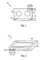
- FIG. 2is a perspective view illustrating one embodiment of a magnetic tape cartridge
- FIG. 3is a schematic view illustrating one embodiment of a group of data stored on a magnetic tape using a helical scan technique
- FIG. 4is a schematic view illustrating one embodiment of a track of data stored on a magnetic tape
- FIG. 5is a schematic view illustrating one embodiment of a block of data stored on a magnetic tape
- FIG. 6is a schematic view illustrating one embodiment of a magnetic tape formatted to include a series of partitions
- FIG. 7is a schematic view illustrating one embodiment of a magnetic tape formatted for use with a magnetic tape cartridge having a non-volatile memory
- FIG. 8Ais a schematic view illustrating one embodiment of a magnetic tape prior to an overwrite operation
- FIG. 8Bis a schematic view illustrating one embodiment of a magnetic tape after an overwrite operation
- FIG. 9is a schematic view illustrating one embodiment of record formats for a non-volatile memory disposed on a magnetic tape cartridge
- FIG. 10is a plan view illustrating one embodiment of a magnetic tape drive 1000 ;
- FIG. 11is a perspective view illustrating one embodiment of a SCSI interface coupled with an internal magnetic tape drive
- FIG. 12is a perspective view illustrating one embodiment of a SCSI interface coupled with an external magnetic tape drive
- FIG. 13is a block diagram illustrating one embodiment of a SCSI interface coupled with a magnetic tape drive.
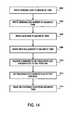
- FIG. 14is a flow diagram illustrating one embodiment of using a flag to read past an EOD marker.
- a magnetic tape having a non-volatile memory that stores a flag enabling a magnetic tape drive to read past an end-of-data (EOD) markeris disclosed herein.
- the EOD markermay indicate the end of the last recorded data on the magnetic tape.
- the flagis stored in the non-volatile memory via a small computer system interface (SCSI) command.
- the flagis stored in the non-volatile memory via an application.
- the flagis stored in the non-volatile memory via a portable electronic device, such as a personal digital assistant (PDA).
- the PDAmay have a radio frequency (RF) module or any other form of wireless communications device such as an infrared (IR) module.
- RFradio frequency
- IRinfrared
- FIG. 1is a plan view illustrating one embodiment of a magnetic tape cartridge 100 .
- Magnetic tape cartridge 100has spools 102 and 104 , around which a magnetic tape 106 is coiled.
- Magnetic tape 106typically has a base, a back coat disposed above one surface of the base, a magnetic layer disposed above the other surface of the base, a protective layer disposed above the magnetic layer, and a lubricant disposed above the protective layer.
- the magnetic layermay be a metal such as cobalt or a cobalt/nickel alloy.
- the magnetic layermay be a ferromagnetic material, such as ferric oxide (Fe2O3).
- the ferric oxidemay be mixed with another metallic oxide such as chromium dioxide (CrO2).
- the magnetic layerbecomes permanently magnetized in the presence of a magnetic field, enabling data to be stored on and retrieved from magnetic tape 106 .
- Magnetic tape 106may be guided by guides 108 and 110 such that a portion of magnetic tape 106 is close to one edge of magnetic tape cartridge 100 .
- a guard panel 112may cover the portion of magnetic tape 106 that is close to the edge of magnetic tape cartridge 100 .
- a non-volatile memory 114may be disposed on or contained within magnetic tape cartridge 100 .
- Non-volatile memory 114may be any type of non-volatile memory, such as Erasable Programmable Read-Only Memory (EPROM), Electrically-Erasable Programmable Read-Only Memory (EEPROM), or flash memory.
- EPROMErasable Programmable Read-Only Memory
- EEPROMElectrically-Erasable Programmable Read-Only Memory
- flash memoryNon-volatile memory 114 may be used to store various types of information about magnetic tape cartridge 100 and magnetic tape 106 , as described below in further detail.
- Magnetic tape cartridge 100may also have an interface 116 to facilitate communication between non-volatile memory 114 and a magnetic tape drive.
- Interface 116may include terminal pins 118 , 120 , 122 , 124 , and 126 . In alternative embodiments, interface 116 may have more or less than five terminal pins.
- the Sony 8 mm AIT tapeincludes a 16 kbit EEPROM chip incorporated into the tape cartridge.
- the EEPROM chipstores information that enables an AIT-compatible tape drive to, among other things, access data at any one of up to 256 partitions in the magnetic tape without rewinding to the beginning of the magnetic tape and reading the system log to find the desired file.
- the Sony 8 mm AIT tapealso includes a 5 pin interface for communicating with an AIT-compatible tape drive.
- FIG. 2is a perspective view illustrating one embodiment of a magnetic tape cartridge 200 .
- magnetic cartridge 200corresponds to magnetic cartridge 100 discussed above with respect to FIG. 1 .
- Magnetic tape cartridge 200may include a casing 202 and a guard panel 204 .
- Magnetic tape cartridge 200also may include a non-volatile memory (not shown) and an interface 206 to facilitate communication between the non-volatile memory and a magnetic tape drive.
- Interface 206may include terminal pins 208 , 210 , 212 , 214 , and 216 .
- FIG. 3is a schematic view illustrating one embodiment of a group 300 of data stored on a magnetic tape 302 using a helical scan technique. Tracks 304 of data are recorded at an angle in relation to the sides of magnetic tape 302 . One group 300 contains 40 tracks 304 . Recording tracks 304 at an angle increases the amount of data that can be stored on magnetic tape 302 .
- datais stored on magnetic tape 302 using a linear recording technique.
- the linear recording techniquemay employ a serpentine recording technique.
- FIG. 4is a schematic view illustrating one embodiment of a track 400 of data stored on a magnetic tape.
- track 400corresponds to track 304 discussed above with respect to FIG. 3 .
- Track 400may be 471 blocks in length. A block is discussed below with respect to FIG. 5 .
- Track 400may include margins 402 and 404 , auto tracking following (ATF) areas 406 , 408 , and 410 , and data areas 412 and 414 .
- Margins 402 and 404are located at either end of track 400 and each may be 4 blocks in length. Following left margin 402 are ATF area 406 , data area 412 , ATF area 408 , data area 414 , and ATF area 410 .
- ATF areas 406 , 408 , and 410provide a closed-loop, self-adjusting path for tape tracking, and each may be 5 blocks in length.
- ATF areas 406 , 408 , and 410enable a magnetic tape drive to self-adjust for tape flutter, thereby allowing successive tracks to be written more closely together for increased recording density.
- Data areas 412 and 414contain user data and each may be 224 blocks in length.
- FIG. 5is a schematic view illustrating one embodiment of a block 500 of data stored on a magnetic tape.
- Block 500includes a sync area 502 , an ID area 504 , a parity area 506 , and a data area 508 .
- Sync area 502may be 1 byte in length.
- ID area 504is used by a magnetic tape drive to locate data, and may be 6 bytes in length.
- Parity area 506may be 2 bytes in length.
- Data area 504may be 64 bytes in
- FIG. 6is a schematic view illustrating one embodiment of a magnetic tape 600 formatted to include a series of partitions 602 , 604 , 606 and 608 .
- Device area 610may be located at the beginning of magnetic tape 600 , and device areas 612 , 614 , and 616 may separate partitions 602 , 604 , 606 and 608 .
- Partitions 602 , 604 , 606 and 608may enable a tape drive to quickly access a particular data file.
- magnetic tape 600may be divided into up to 256 partitions.
- Device areas 610 , 612 , 614 , and 616provide load/unload points for a magnetic tape drive. Device areas located between partitions enable a magnetic tape drive to load or unload magnetic tape 600 at any partition, rather than requiring the magnetic tape drive to load or unload magnetic tape 600 before the first partition 602 .
- FIG. 7is a schematic view illustrating one embodiment of a magnetic tape 700 formatted for use with a magnetic tape cartridge having a non-volatile memory.
- Magnetic tape 700includes a series of partitions 702 , 704 , 706 , 708 , and 710 .
- Partition 706is divided into a reference area 712 , a position tolerance band 714 , a system area 716 , a data area 718 , an end of data (EOD) marker 720 , and a device area 722 .
- EOD marker 720may indicate the end of the last recorded data on magnetic tape 700 .
- System area 716is divided into a system preamble 724 , a system log 726 , a system postamble 728 , a position tolerance band 730 , and a vendor group preamble 732 .
- Data area 718is divided into vendor group 734 , groups 736 , 738 , and 740 (such as group 300 described above with reference to FIG. 3 ), and amble frame 742 .
- FIG. 8Ais a schematic view illustrating one embodiment of a magnetic tape 800 prior to an overwrite operation.
- magnetic tape 800may correspond to magnetic tape 700 described above with reference to FIG. 7 .
- Magnetic tape 800may have a series of partitions 802 , 804 , and 806 .
- Partition 802 , 804 , or 806may correspond to partition 702 , 704 , 706 , 708 , or 710 described above with reference to FIG. 7 .
- Device areas 808 and 810may be located, respectively, before and after partition 804 , and may provide load/unload points for a magnetic tape drive.
- Device area 808 or 810may correspond to device area 722 described above with reference to FIG. 7 .
- Magnetic tape 800may have original data 812 that is written to magnetic tape 800 during an initial write operation. Data may also be stored in partitions 802 and 806 .
- An original EOD marker 814may indicate the end of original data 812 within partition 804 .
- Original EOD marker 814may correspond to EOD marker 720 described above with reference to FIG. 7 . If partitions 802 and 806 also contain data, then partitions 802 and 806 may also contain an EOD marker indicating the end of data within each partition. If the entire length of partition 804 is not filled with original data 812 , there may be unused tape 816 between original EOD marker 814 and device area 810 . No data is stored in unused tape 816 .
- FIG. 8Bis a schematic view illustrating one embodiment of a magnetic tape 850 after an overwrite operation.
- Magnetic tape 850may have a series of partitions 852 , 854 , and 856 .
- Partitions 852 , 854 , and 856may correspond to partitions 802 , 804 , and 806 described above with reference to FIG. 8 A.
- Device areas 858 and 860may be located, respectively, before and after partition 854 , and may provide load/unload points for a magnetic tape drive.
- Device areas 858 and 860may correspond to device areas 808 and 810 described above with reference to FIG. 8 A.
- Magnetic tape 850may have new data 862 that is written to magnetic tape 850 during an overwrite operation.
- a new EOD marker 864may indicate the end of new data 862 within partition 854 .
- Magnetic tape 850may include recoverable data 866 .
- Recoverable data 866may be data that was written to magnetic tape 850 during an initial write operation and not overwritten during an overwrite operation.
- recoverable data 866may correspond to the portion of original data 812 , described above with reference to FIG. 8A, that is located to the right of new EOD marker 864 .
- a usermay wish to read recoverable data 866 to recover the portion of original data 812 that was not overwritten during the overwrite operation.
- Magnetic tape 850may also include original EOD marker 868 that indicates the end of recoverable data 866 .
- Original EOD marker 814may correspond to original EOD marker 808 described above with reference to FIG. 8 A. If less than the entire length of partition 854 is filled with new data 862 and recoverable data 866 , there may be unused tape 870 between original EOD marker 868 and device area 860 .
- FIG. 9is a schematic view illustrating one embodiment of a record format 900 for a non-volatile memory disposed on a magnetic tape cartridge.
- the non-volatile memory that contains record format 900is non-volatile memory 114 described above with reference to FIG. 1 .
- Record format 900may include a header 902 , an absolute volume map 904 , volume information 906 , a user volume note 908 , partition information 910 , and a user partition note 912 .
- a read-past-EOD marker flagmay be stored in one of these locations within the non-volatile memory.
- FIG. 10is a plan view illustrating one embodiment of a magnetic tape drive 1000 .
- magnetic tape drive 1000is compatible with a magnetic tape cartridge 1002 having a non-volatile memory (not shown).
- Magnetic tape cartridge 1002may be magnetic tape cartridge 100 described above with reference to FIG. 1 .
- Magnetic tape drivemay include sprockets 1004 and 1006 that engage spools 1008 and 1010 in magnetic tape cartridge 1002 .
- a capstan shaft 1012is connected to a capstan motor 1014 .
- a pinch roller 1016applies pressure to a magnetic tape 1018 such that magnetic tape 1018 is tight against capstan shaft 1012 .
- Capstan motor 1014rotates at an approximately constant velocity, causing magnetic tape 1018 to move past one or more read/write heads 1020 .
- Guides 1022 , 1024 , 1026 , and 1028 , slant pins 1030 and 1032 , and swing arm 1034guide magnetic tape 1018 past read/write head 1020 .
- Read/write head 1020typically is a ring-shaped electromagnet having a ferrous core. The core is broken at an air gap, around which is a fringing magnetic field.
- magnetic tape drive 1000passes magnetic tape 1018 through the fringing magnetic field at an approximately constant velocity while a signal current is applied to the electromagnet, causing magnetic tape 1018 to become magnetized.
- magnetic tape drive 1000passes magnetic tape 1018 through the fringing magnetic field at an approximately constant velocity, and the magnetic field created by the magnetization of magnetic tape 1018 induces a voltage in the electromagnet that can be interpreted as data by magnetic tape drive 1000 .
- Magnetic tape drive 1000may be an internal magnetic tape drive or an external magnetic tape drive.
- An example of an internal tape drive adapted to communicate with a non-volatile memory in a magnetic tape cartridgeis the Sony AIT-2 Internal Drive, manufactured by Sony Electronics, Inc. of Tokyo, Japan.
- An example of an external tape drive adapted to communicate with a non-volatile memory in a magnetic tape cartridgeis the Sony AIT-2 External Drive, manufactured by Sony Electronics, Inc. of Tokyo, Japan.
- FIG. 11is a perspective view illustrating one embodiment of a SCSI interface 1100 .
- SCSI interface 1100includes a host adapter 1102 that is coupled with an internal magnetic tape drive 1104 .
- Host adapter 1102may be an expansion board that plugs into an expansion slot in a computer.
- the computeris a network server.
- a cable 1106connects host adapter 1102 with internal magnetic tape drive 1104 .
- a second internal magnetic tape drive 1108is connected to internal magnetic tape drive 1104 via a second cable 1110 .
- SCSI interface 1100enables multiple SCSI peripheral devices, such as internal magnetic tape drive 1104 and second internal magnetic tape drive 1108 , to connect to a single host adapter 1102 .
- Each SCSI peripheral devicehas a first port (not shown) and a second port (not shown).
- the first port in internal magnetic tape drive 1104is connected directly to host adapter 1102 via cable 1106 .
- the first port in second internal magnetic tape drive 1108connects with the second port in internal magnetic tape drive 1104 via second cable 1110 .
- multiple internal tape drivesmay be connected with a single SCSI host adapter 1102 .
- FIG. 12is a perspective view illustrating another embodiment of a SCSI interface 1200 .
- SCSI interface 1200includes a host adapter 1202 that is coupled with an external magnetic tape drive 1204 .
- Host adapter 1202may be an expansion board that plugs into an expansion slot in a computer.
- the computeris a network server.
- a cable 1206connects host adapter 1202 with external magnetic tape drive 1204 .
- a second external magnetic tape drive 1208is connected to external magnetic tape drive 1204 via a second cable 1210 .
- host adapter 1202may be connected with both internal magnetic tape drives, such as internal magnetic tape drive 1104 and second internal magnetic tape drive 1108 discussed above with reference to FIG. 11, and external magnetic tape drives, such as external magnetic tape drive 1204 and second external magnetic tape drive 1208 .
- FIG. 13is a block diagram illustrating one embodiment of a computer system 1300 having a SCSI interface.
- Computer systemincludes a processor 1302 , memory 1304 , and input/output devices 1306 .
- Processor 1302 , memory 1304 , and input/output devices 1306are connected via system bus 1308 .
- Memory 1304is configured to store instructions that, when executed by processor 1302 , cause computer system 1300 to perform the method described herein.
- Input/output devices 1306may include a keyboard, a mouse or other pointing device, a digital camera, a scanner, a disk drive, a tape drive, a monitor, and a printer.
- Computer systemmay also include SCSI host adapter 1310 .
- SCSI host adapter 1310may be SCSI host adapter 1102 discussed above with reference to FIG. 11, or SCSI host adapter 1202 discussed above with reference to FIG. 12 .
- SCSI host adapter 1310is connected to processor 1302 , memory 1304 , and input/output devices 1306 via system bus 1308 .
- Multiple internal peripheral devicesmay be connected to SCSI host adapter 1310 via internal SCSI bus 1312 .
- Internal peripheral devicesmay include internal magnetic tape drive 1314 and second internal magnetic tape drive 1316 .
- Multiple external peripheral devicesmay be connected to SCSI host adapter 1310 via external SCSI bus 1318 .
- External peripheral devicesmay include external magnetic tape drive 1320 and second external magnetic tape drive 1322 .
- Each peripheral devicemay contain a controller (not shown).
- the controllercontrols the exchange of information between the peripheral and processor 1302 .
- the controllercontrols the exchange of information between a magnetic tape cartridge inserted in the magnetic tape drive and processor 1302 .
- the controlleralso controls the exchange of information between the non-volatile memory and processor 1302 .
- the exchange of information between the non-volatile memory and processor 1302occurs via SCSI host adapter 1310 .
- SCSI host adapter 1310provides a SCSI command to a magnetic tape drive, causing the magnetic tape drive to set a read-past-EOD marker flag to the “on” position.
- the read-past-EOD marker flagmay be located in non-volatile memory in a magnetic tape cartridge inserted into the magnetic tape drive.
- the magnetic tape drivewill read past an EOD marker stored on the magnetic tape inside the magnetic tape cartridge.
- the read-past-EOD markeris in the “off” position, the magnetic tape drive will not read past an EOD marker on the magnetic tape.
- FIG. 14is a flow diagram illustrating one embodiment of using a flag to read past an EOD marker.
- Original datais written to a magnetic tape, 1402 .
- An original EOD markeris written to the magnetic tape, 1404 .
- the original EOD markerimmediately follows the last bit of original data written to magnetic tape during the write operation of step 1402 .
- original EOD markermay indicate to a magnetic tape drive the location of the last bit of original data written to the magnetic tape during the write operation of step 1402 .
- new datais written to the magnetic tape, 1406 .
- the new datamay be written during an overwrite operation, in which at least a portion of the original data written in step 1402 is overwritten.
- a new EOD markeris then written to the magnetic tape, 1408 .
- the new EOD markerimmediately follows the last bit of new data written to the magnetic tape during the write operation of step 1406 .
- new EOD markermay indicate to a magnetic tape drive the location of the last bit of new data written to the magnetic tape during the overwrite operation of step 1406 .
- a commandis received to set a read-past-EOD marker flat to an “on” position, 1410 .
- the commandis a SCSI command received from a SCSI host adapter.
- the read-past-EOD marker flagmay be located in a non-volatile memory coupled with a magnetic tape cartridge.
- the read-past-EOD marker flagis then set to the “on” position, 1412 .
- a controller in a magnetic drivesets the read-past-EOD marker flag to the “on” position by setting a bit in the non-volatile memory to a particular logic value.
- a magnetic tape drivewill read past an EOD marker written to the magnetic tape during the write operation of step 1408 when the read-past-EOD marker flag is set to the “on” position.
- the magnetic tapewill not read past the EOD marker when the read-past-EOD marker flag is set to the “off” position.
- the magnetic tape driveis able to read recoverable data that was written to the magnetic tape during the write operation of step 1402 and remains on the magnetic tape after the write operation of step 1406 .
Landscapes
- Engineering & Computer Science (AREA)
- Theoretical Computer Science (AREA)
- Human Computer Interaction (AREA)
- Physics & Mathematics (AREA)
- General Engineering & Computer Science (AREA)
- General Physics & Mathematics (AREA)
- Computer Security & Cryptography (AREA)
- Signal Processing For Digital Recording And Reproducing (AREA)
Abstract
Description
Claims (15)
Priority Applications (1)
| Application Number | Priority Date | Filing Date | Title |
|---|---|---|---|
| US09/884,803US6775087B2 (en) | 2001-06-18 | 2001-06-18 | Method and apparatus to read past EOD marker |
Applications Claiming Priority (1)
| Application Number | Priority Date | Filing Date | Title |
|---|---|---|---|
| US09/884,803US6775087B2 (en) | 2001-06-18 | 2001-06-18 | Method and apparatus to read past EOD marker |
Publications (2)
| Publication Number | Publication Date |
|---|---|
| US20030043492A1 US20030043492A1 (en) | 2003-03-06 |
| US6775087B2true US6775087B2 (en) | 2004-08-10 |
Family
ID=25385428
Family Applications (1)
| Application Number | Title | Priority Date | Filing Date |
|---|---|---|---|
| US09/884,803Expired - Fee RelatedUS6775087B2 (en) | 2001-06-18 | 2001-06-18 | Method and apparatus to read past EOD marker |
Country Status (1)
| Country | Link |
|---|---|
| US (1) | US6775087B2 (en) |
Cited By (6)
| Publication number | Priority date | Publication date | Assignee | Title |
|---|---|---|---|---|
| US20050086428A1 (en)* | 2003-10-16 | 2005-04-21 | Fujitsu Limited | Magnetic tape unit |
| US20050129239A1 (en)* | 2002-11-21 | 2005-06-16 | Farley Rodney J. | Secure terminal data loader apparatus and method for a mobile platform |
| US20050223162A1 (en)* | 2004-03-20 | 2005-10-06 | Evans Rhys W | Data storage method and apparatus employing a tape cartridge for storing worm data |
| US20050235103A1 (en)* | 2004-04-15 | 2005-10-20 | Saliba George A | Methods and systems for overwrite protected storage media |
| US7139141B1 (en)* | 2003-05-12 | 2006-11-21 | Storage Technology Corporation | System and method for read/write optimization |
| US20070242376A1 (en)* | 2006-03-29 | 2007-10-18 | Toshiyuki Nakagawa | Magnetic recording and reproduction method, recording apparatus, reproduction apparatus and magnetic recording medium |
Families Citing this family (2)
| Publication number | Priority date | Publication date | Assignee | Title |
|---|---|---|---|---|
| US7414803B2 (en)* | 2005-05-19 | 2008-08-19 | Quantum Corporation | Write protected magnetic storage media and associated methods |
| US7783882B2 (en)* | 2006-09-07 | 2010-08-24 | International Business Machines Corporation | Recovering remnant encrypted data on a removable storage media |
Citations (30)
| Publication number | Priority date | Publication date | Assignee | Title |
|---|---|---|---|---|
| US4682292A (en)* | 1984-07-23 | 1987-07-21 | United Technologies Corporation | Fault tolerant flight data recorder |
| US5084787A (en)* | 1990-03-08 | 1992-01-28 | The United States Of America As Represented By The United States Department Of Energy | Method and apparatus for data decoding and processing |
| US5163136A (en)* | 1989-11-13 | 1992-11-10 | Archive Corporation | System for assembling playback data frames using indexed frame buffer group according to logical frame numbers in valid subcode or frame header |
| US5377056A (en)* | 1990-07-25 | 1994-12-27 | Hewlett-Packard Company | Digital data tape reading device |
| US5384669A (en) | 1989-06-28 | 1995-01-24 | International Business Machines Corporation | Combining small records into a single record block for recording on a record media |
| US5448427A (en)* | 1989-08-21 | 1995-09-05 | Hitachi, Ltd. | Magnetic recording and reproducing apparatus |
| US5546246A (en)* | 1994-01-13 | 1996-08-13 | Exabyte Corporation | Magnetic tape drive with end-of-track block directory |
| US5638229A (en)* | 1991-11-29 | 1997-06-10 | Canon Kabushiki Kaisha | Method for detecting an information recorded position in an information reproducing apparatus |
| US5671350A (en) | 1993-09-30 | 1997-09-23 | Sybase, Inc. | Data backup system with methods for stripe affinity backup to multiple archive devices |
| US5710676A (en)* | 1996-03-12 | 1998-01-20 | International Business Machines Corporation | Pre-formatting of a storage media having fixed-size partitions |
| US5758151A (en) | 1994-12-09 | 1998-05-26 | Storage Technology Corporation | Serial data storage for multiple access demand |
| US5757571A (en) | 1996-03-12 | 1998-05-26 | International Business Machines Corporation | Flexible-capacity scaling for efficient access of ordered data stored on magnetic tape media |
| US5818652A (en)* | 1995-06-23 | 1998-10-06 | Sony Corporation | Device for reproducing a recording medium having plural recording areas |
| US5823486A (en) | 1997-02-07 | 1998-10-20 | Margaret K. Smith | Universal flexible arm |
| US6023388A (en)* | 1996-06-27 | 2000-02-08 | Sony Corporation | Data recording apparatus and data reproducing apparatus |
| US6029229A (en) | 1997-01-29 | 2000-02-22 | Emc Corporation | Digital data storage subsystem including directory for efficiently providing formatting information for stored records |
| US6093925A (en)* | 1996-09-06 | 2000-07-25 | Funai Electric Co., Ltd. | Reel sensor and start/finish end detecting device |
| US6134066A (en)* | 1997-03-21 | 2000-10-17 | Sony Corporation | Recording and reproducing apparatus using tape cassette for updating attribute information in write protect mode |
| US6182191B1 (en)* | 1997-02-27 | 2001-01-30 | Sony Precision Technology Inc. | Recording and reproducing system |
| US6288862B1 (en) | 1999-07-30 | 2001-09-11 | Storage Technology Corporation | Method and mechanism to distinguish valid from outdated recording blocks in a tape drive |
| US6301067B1 (en) | 1997-09-12 | 2001-10-09 | Sony Corporation | Tape cassette and a tape recording apparatus |
| US6307700B1 (en) | 1997-09-12 | 2001-10-23 | Sony Corporation | Tape recording and/or reproducing apparatus and tape ejecting method |
| US6366987B1 (en) | 1998-08-13 | 2002-04-02 | Emc Corporation | Computer data storage physical backup and logical restore |
| US6417978B1 (en)* | 1997-12-25 | 2002-07-09 | Sony Corporation | Recording medium searching method and recording medium processing device using the same method |
| US6501612B1 (en)* | 1998-09-30 | 2002-12-31 | Sony Corporation | Recording medium and tape drive suitable for the same |
| US6535344B1 (en)* | 1998-12-11 | 2003-03-18 | Sony Corporation | Tape drive unit and recording medium |
| US6580576B1 (en)* | 1998-12-11 | 2003-06-17 | Sony Corporation | Tape driving apparatus and recording medium |
| US6587298B1 (en)* | 1999-07-30 | 2003-07-01 | Sony Corporation | Device for reading and writing tape recording medium, accessing method therefor, and recording medium |
| US6603624B1 (en)* | 1998-12-11 | 2003-08-05 | Sony Corporation | Tape drive unit and recording medium |
| US6618795B2 (en)* | 2001-01-24 | 2003-09-09 | Sony Corporation | Method and apparatus for concurrent access to a sequential device |
- 2001
- 2001-06-18USUS09/884,803patent/US6775087B2/ennot_activeExpired - Fee Related
Patent Citations (31)
| Publication number | Priority date | Publication date | Assignee | Title |
|---|---|---|---|---|
| US4682292A (en)* | 1984-07-23 | 1987-07-21 | United Technologies Corporation | Fault tolerant flight data recorder |
| US5384669A (en) | 1989-06-28 | 1995-01-24 | International Business Machines Corporation | Combining small records into a single record block for recording on a record media |
| US5608585A (en)* | 1989-08-21 | 1997-03-04 | Hitachi, Ltd. | Magnetic recording and reproducing apparatus with repositioning stop mode |
| US5448427A (en)* | 1989-08-21 | 1995-09-05 | Hitachi, Ltd. | Magnetic recording and reproducing apparatus |
| US5163136A (en)* | 1989-11-13 | 1992-11-10 | Archive Corporation | System for assembling playback data frames using indexed frame buffer group according to logical frame numbers in valid subcode or frame header |
| US5084787A (en)* | 1990-03-08 | 1992-01-28 | The United States Of America As Represented By The United States Department Of Energy | Method and apparatus for data decoding and processing |
| US5377056A (en)* | 1990-07-25 | 1994-12-27 | Hewlett-Packard Company | Digital data tape reading device |
| US5638229A (en)* | 1991-11-29 | 1997-06-10 | Canon Kabushiki Kaisha | Method for detecting an information recorded position in an information reproducing apparatus |
| US5671350A (en) | 1993-09-30 | 1997-09-23 | Sybase, Inc. | Data backup system with methods for stripe affinity backup to multiple archive devices |
| US5546246A (en)* | 1994-01-13 | 1996-08-13 | Exabyte Corporation | Magnetic tape drive with end-of-track block directory |
| US5758151A (en) | 1994-12-09 | 1998-05-26 | Storage Technology Corporation | Serial data storage for multiple access demand |
| US5818652A (en)* | 1995-06-23 | 1998-10-06 | Sony Corporation | Device for reproducing a recording medium having plural recording areas |
| US5710676A (en)* | 1996-03-12 | 1998-01-20 | International Business Machines Corporation | Pre-formatting of a storage media having fixed-size partitions |
| US5757571A (en) | 1996-03-12 | 1998-05-26 | International Business Machines Corporation | Flexible-capacity scaling for efficient access of ordered data stored on magnetic tape media |
| US6023388A (en)* | 1996-06-27 | 2000-02-08 | Sony Corporation | Data recording apparatus and data reproducing apparatus |
| US6093925A (en)* | 1996-09-06 | 2000-07-25 | Funai Electric Co., Ltd. | Reel sensor and start/finish end detecting device |
| US6029229A (en) | 1997-01-29 | 2000-02-22 | Emc Corporation | Digital data storage subsystem including directory for efficiently providing formatting information for stored records |
| US5823486A (en) | 1997-02-07 | 1998-10-20 | Margaret K. Smith | Universal flexible arm |
| US6182191B1 (en)* | 1997-02-27 | 2001-01-30 | Sony Precision Technology Inc. | Recording and reproducing system |
| US6134066A (en)* | 1997-03-21 | 2000-10-17 | Sony Corporation | Recording and reproducing apparatus using tape cassette for updating attribute information in write protect mode |
| US6307700B1 (en) | 1997-09-12 | 2001-10-23 | Sony Corporation | Tape recording and/or reproducing apparatus and tape ejecting method |
| US6301067B1 (en) | 1997-09-12 | 2001-10-09 | Sony Corporation | Tape cassette and a tape recording apparatus |
| US6417978B1 (en)* | 1997-12-25 | 2002-07-09 | Sony Corporation | Recording medium searching method and recording medium processing device using the same method |
| US6366987B1 (en) | 1998-08-13 | 2002-04-02 | Emc Corporation | Computer data storage physical backup and logical restore |
| US6501612B1 (en)* | 1998-09-30 | 2002-12-31 | Sony Corporation | Recording medium and tape drive suitable for the same |
| US6535344B1 (en)* | 1998-12-11 | 2003-03-18 | Sony Corporation | Tape drive unit and recording medium |
| US6580576B1 (en)* | 1998-12-11 | 2003-06-17 | Sony Corporation | Tape driving apparatus and recording medium |
| US6603624B1 (en)* | 1998-12-11 | 2003-08-05 | Sony Corporation | Tape drive unit and recording medium |
| US6288862B1 (en) | 1999-07-30 | 2001-09-11 | Storage Technology Corporation | Method and mechanism to distinguish valid from outdated recording blocks in a tape drive |
| US6587298B1 (en)* | 1999-07-30 | 2003-07-01 | Sony Corporation | Device for reading and writing tape recording medium, accessing method therefor, and recording medium |
| US6618795B2 (en)* | 2001-01-24 | 2003-09-09 | Sony Corporation | Method and apparatus for concurrent access to a sequential device |
Non-Patent Citations (1)
| Title |
|---|
| Rosenblum et al., "The Design and Implementation of a Log-Structured File System:, ACM Transactions on Computer Systems", vol. 10, No. 1, Feb. 1992, pp. 26-52. |
Cited By (13)
| Publication number | Priority date | Publication date | Assignee | Title |
|---|---|---|---|---|
| US20100008503A1 (en)* | 2002-11-21 | 2010-01-14 | Rodney Farley | Secure Terminal Data Loader Apparatus and Method for a Mobile Platform |
| US20050129239A1 (en)* | 2002-11-21 | 2005-06-16 | Farley Rodney J. | Secure terminal data loader apparatus and method for a mobile platform |
| US8723692B2 (en) | 2002-11-21 | 2014-05-13 | Systems And Software Enterprises, Llc | Secure terminal data loader apparatus and method for a mobile platform |
| US8126147B2 (en) | 2002-11-21 | 2012-02-28 | Systems And Software Enterprises, Inc. | Secure terminal data loader system and in-flight entertainment management system |
| US7580528B2 (en)* | 2002-11-21 | 2009-08-25 | Systems And Software Enterprises, Inc. | Secure terminal data loader apparatus and method for a mobile platform |
| US7139141B1 (en)* | 2003-05-12 | 2006-11-21 | Storage Technology Corporation | System and method for read/write optimization |
| US20050086428A1 (en)* | 2003-10-16 | 2005-04-21 | Fujitsu Limited | Magnetic tape unit |
| US20050223162A1 (en)* | 2004-03-20 | 2005-10-06 | Evans Rhys W | Data storage method and apparatus employing a tape cartridge for storing worm data |
| US7441075B2 (en)* | 2004-03-20 | 2008-10-21 | Hewlett-Packard Development Company, L.P. | Data storage method and apparatus employing a tape cartridge for storing WORM data |
| US20050235103A1 (en)* | 2004-04-15 | 2005-10-20 | Saliba George A | Methods and systems for overwrite protected storage media |
| US7224545B2 (en)* | 2004-04-15 | 2007-05-29 | Quantum Corporation | Methods and systems for overwrite protected storage media |
| US7813066B2 (en)* | 2006-03-29 | 2010-10-12 | Sony Corporation | Magnetic recording and reproduction method, recording apparatus, reproduction apparatus and magnetic recording medium |
| US20070242376A1 (en)* | 2006-03-29 | 2007-10-18 | Toshiyuki Nakagawa | Magnetic recording and reproduction method, recording apparatus, reproduction apparatus and magnetic recording medium |
Also Published As
| Publication number | Publication date |
|---|---|
| US20030043492A1 (en) | 2003-03-06 |
Similar Documents
| Publication | Publication Date | Title |
|---|---|---|
| JP4672824B2 (en) | Tape drive device, recording medium | |
| US9053745B2 (en) | Method for writing file on tape medium that can be read at high speed | |
| US7650461B2 (en) | Magnetic tape write once overwrite protection | |
| US7224545B2 (en) | Methods and systems for overwrite protected storage media | |
| US6937411B2 (en) | Method, system, program, and storage cartridge for storing data in a storage medium | |
| US6674599B1 (en) | Data storage method, apparatus and medium | |
| JP5636115B2 (en) | Data alteration detection method and file system for tape drives | |
| US6775087B2 (en) | Method and apparatus to read past EOD marker | |
| US7143232B2 (en) | Method, system, and program for maintaining a directory for data written to a storage medium | |
| US7103741B2 (en) | Tape drive apparatus and recording and/or reproducing method | |
| US7016137B2 (en) | Tape drive apparatus, recording and/or reproducing method, and recording medium | |
| JP4946126B2 (en) | Data recording method and data recording apparatus | |
| US6937412B1 (en) | Method and apparatus for creating a format identification block on a magnetic tape | |
| US7768733B2 (en) | Method for erasing data from magnetic tape storage media | |
| US7167332B2 (en) | Method and apparatus for recording data onto a recording medium including warning of the approach to an end of medium position | |
| US7100010B2 (en) | Tape drive apparatus, recording and/or reproducing method, and recording medium | |
| JPH0721070A (en) | Signal processor | |
| JP4513186B2 (en) | Information recording / reproducing device | |
| JP4766085B2 (en) | Tape drive device, recording medium, and recording / reproducing method | |
| GB2410605A (en) | Write once read many tape drive | |
| JPH10112164A (en) | Magnetic tape recording / reproducing device | |
| JP2001297538A (en) | Digital data storage device | |
| JPH0737210A (en) | Data recorder |
Legal Events
| Date | Code | Title | Description |
|---|---|---|---|
| AS | Assignment | Owner name:SONY CORPORATION, JAPAN Free format text:ASSIGNMENT OF ASSIGNORS INTEREST;ASSIGNORS:CHAN, NATHAN;DESAI, PARESH J.;CHAN, JOSEPH;REEL/FRAME:011924/0086 Effective date:20010612 Owner name:SONY ELECTRONICS, INC., NEW JERSEY Free format text:ASSIGNMENT OF ASSIGNORS INTEREST;ASSIGNORS:CHAN, NATHAN;DESAI, PARESH J.;CHAN, JOSEPH;REEL/FRAME:011924/0086 Effective date:20010612 | |
| AS | Assignment | Owner name:SONY CORPORATION, JAPAN Free format text:CORRECTED RECORDATION FORM COVER SHEET TO CORRECT THE NAME OF THE THIRD INVENTOR AND THE ADDRESS OF THE FIRST ASSIGNEE. PREVIOUSLY RECORDED AT REEL/FRAME 011924/0086 (ASSIGNMENT OF ASSIGNOR'S INTEREST);ASSIGNORS:CHAN, NATHAN;DESAI, PARESH J.;TORII, SHINICHIRO KEN;REEL/FRAME:012652/0880 Effective date:20010612 Owner name:SONY ELECTRONICS INC, NEW JERSEY Free format text:CORRECTED RECORDATION FORM COVER SHEET TO CORRECT THE NAME OF THE THIRD INVENTOR AND THE ADDRESS OF THE FIRST ASSIGNEE. PREVIOUSLY RECORDED AT REEL/FRAME 011924/0086 (ASSIGNMENT OF ASSIGNOR'S INTEREST);ASSIGNORS:CHAN, NATHAN;DESAI, PARESH J.;TORII, SHINICHIRO KEN;REEL/FRAME:012652/0880 Effective date:20010612 | |
| FPAY | Fee payment | Year of fee payment:4 | |
| REMI | Maintenance fee reminder mailed | ||
| FPAY | Fee payment | Year of fee payment:8 | |
| REMI | Maintenance fee reminder mailed | ||
| LAPS | Lapse for failure to pay maintenance fees | ||
| STCH | Information on status: patent discontinuation | Free format text:PATENT EXPIRED DUE TO NONPAYMENT OF MAINTENANCE FEES UNDER 37 CFR 1.362 | |
| FP | Lapsed due to failure to pay maintenance fee | Effective date:20160810 |