US6774808B1 - Electromechanical lock for components - Google Patents
Electromechanical lock for componentsDownload PDFInfo
- Publication number
- US6774808B1 US6774808B1US09/572,149US57214900AUS6774808B1US 6774808 B1US6774808 B1US 6774808B1US 57214900 AUS57214900 AUS 57214900AUS 6774808 B1US6774808 B1US 6774808B1
- Authority
- US
- United States
- Prior art keywords
- carrier
- coupled
- component
- lock
- assembly
- Prior art date
- Legal status (The legal status is an assumption and is not a legal conclusion. Google has not performed a legal analysis and makes no representation as to the accuracy of the status listed.)
- Expired - Lifetime
Links
Images


Classifications
- G—PHYSICS
- G06—COMPUTING OR CALCULATING; COUNTING
- G06F—ELECTRIC DIGITAL DATA PROCESSING
- G06F1/00—Details not covered by groups G06F3/00 - G06F13/00 and G06F21/00
- G06F1/16—Constructional details or arrangements
- G06F1/18—Packaging or power distribution
- G06F1/183—Internal mounting support structures, e.g. for printed circuit boards, internal connecting means
- G06F1/187—Mounting of fixed and removable disk drives
- G—PHYSICS
- G06—COMPUTING OR CALCULATING; COUNTING
- G06F—ELECTRIC DIGITAL DATA PROCESSING
- G06F1/00—Details not covered by groups G06F3/00 - G06F13/00 and G06F21/00
- G06F1/16—Constructional details or arrangements
- G06F1/18—Packaging or power distribution
- G06F1/183—Internal mounting support structures, e.g. for printed circuit boards, internal connecting means
- G06F1/184—Mounting of motherboards
- G—PHYSICS
- G06—COMPUTING OR CALCULATING; COUNTING
- G06F—ELECTRIC DIGITAL DATA PROCESSING
- G06F11/00—Error detection; Error correction; Monitoring
- G06F11/004—Error avoidance
- G—PHYSICS
- G06—COMPUTING OR CALCULATING; COUNTING
- G06F—ELECTRIC DIGITAL DATA PROCESSING
- G06F11/00—Error detection; Error correction; Monitoring
- G06F11/30—Monitoring
- G06F11/32—Monitoring with visual or acoustical indication of the functioning of the machine
- G06F11/324—Display of status information
- G06F11/325—Display of status information by lamps or LED's
- Y—GENERAL TAGGING OF NEW TECHNOLOGICAL DEVELOPMENTS; GENERAL TAGGING OF CROSS-SECTIONAL TECHNOLOGIES SPANNING OVER SEVERAL SECTIONS OF THE IPC; TECHNICAL SUBJECTS COVERED BY FORMER USPC CROSS-REFERENCE ART COLLECTIONS [XRACs] AND DIGESTS
- Y10—TECHNICAL SUBJECTS COVERED BY FORMER USPC
- Y10T—TECHNICAL SUBJECTS COVERED BY FORMER US CLASSIFICATION
- Y10T70/00—Locks
- Y10T70/70—Operating mechanism
- Y10T70/7051—Using a powered device [e.g., motor]
- Y10T70/7062—Electrical type [e.g., solenoid]
Definitions
- the present inventionrelates to mechanical and electrical apparatus for connecting and disconnecting components of a computer system. More particularly, the present invention relates to a mechanism engaging and disengaging components from the system while it is operating.
- Typical hot swap technologyemploys resources for signaling the system and components in the system about an intention to remove or replace a component. Also, the technology includes routines that stabilize communications among the components, and manage the distribution of power to components during the exchange.
- the present inventionprovides a mechanism that prevents premature disengagement of components the computer system.
- An indicatorshows that a component is ready to be removed and positively identifies which of multiple identical components should be removed.
- the mechanismis able to block attempted removal of the wrong component or of a component if the electrical processes necessary for hot swap have yet to complete.
- an operatorexpects to apply a relatively light force to remove or insert the component.
- the light force appliedminimizes the chance of mechanical damage to the system.
- the resultis a substantially more reliable system, that is less prone to damage during hot swap operation and less prone to removal of the wrong component.
- the present inventionincludes a module for a computer system, the system including a chassis having at least one compartment for accepting the module, and processing resources, comprising: a carrier adapted to fit within the compartment in the chassis with a component mounted inside; a connector adapted to mate with a corresponding element in the computer chassis upon engagement of the module; and means, coupled with the carrier, for engaging and disengaging the component with the system.
- the means for engagingmay leverage an insertion force applied to the carrier to mate the connector with the corresponding elements in the chassis.
- Itmay include a pivotal handle arm coupled to the carrier defining a travel guide; a rotatable hub coupled with the carrier having a protrusion which engage the travel guide; a first lever arm, coupled between the hub and a first engagement member, the engagement member positioned near the lateral edge of the carrier to engage the chassis when the handle arm is moved to an inserted position.
- the movement of the handle arm toward the inserted positionrotates the hub and directs the first lever arm to rotate the engagement member to engage the chassis.
- the first engagement membermay include a catch which engages insertion and extraction stop mounted on the chassis.
- first lever arm and first engagement membermay be mirrored by a second lever arm coupled to the hub and a second engagement member coupled to the second lever arm.
- These elements positioned on opposing lateral edges of the carriermay form a structure adapted to apply a substantially balanced force.
- Another feature of the present inventionincludes a lock in communication with the processing resources which prevents disengagement of the carrier absent an enable signal provided by the processing resources.
- An alternative embodiment of the present inventionis an assembly for engaging a component to a computer system, the assembly comprising: a carrier adapted to retain the component and to be inserted within the chassis of the computer system; a handle arm coupled to the carrier; a detector coupled to the carrier and the handle arm, the detector detecting movement to actuate a lock; and a lock blocking movement of the carrier when engaged.
- This embodimentmay further include logic associated with a computer system and coupled to the lock to selectively override the detector and de-actuate the lock when the component is ready for removal.
- the detectormay provide a signal to actuate the lock and the logic may provide a control signal to selectively de-actuate the lock.
- a handlemounted on the handle arm and a trigger mounted on the handle, the trigger having a released position in which it is biased and a depressed position, the trigger applying a force to the detector when the trigger is in its released position.
- the detectoris coupled to the trigger by a detector surface having a biased distal end that extends to meet the trigger, the biased distal end having a raised position in which it is biased and a depressed position, the biased distal end being coupled to actuate the lock when in its raised position.
- the lockalternatively comprises a cam and a solenoid or it comprises a solenoid secured to the carrier and having a rod, the rod being slidable between an extended position in which it is biased and a retracted position, and a cam secured to the handle arm and movable between a locked position for resisting movement of the handle arm and an extended position, the cam adapted to engage the rod and move into the unlocked position when the rod is in the extended position.
- the cammay be pivotal in a plane that is substantially parallel to the handle arm.
- the logicshould include resources for receiving a request to remove component and resources for determining whether the component is ready for removal from the computer system.
- the logicis coupled to a graphic user interface.
- the logicmay includes resources for enabling an indicator light proximate to the component being removed to signal when the component is ready for removal.
- the present inventionincludes an assembly for engaging a component to computer system, comprising: a carrier having a front end and a back end, adapted to retain the component and to be inserted within the chassis coupled with the component and a connector adapted to mate with a corresponding element in the computer chassis; a pivotal handle arm defining a travel guide; a rotatable hub coupled with the carrier and having a protrusion engaging the travel guide; a first lever arm coupled between the hub and a first engagement member, positioned to engage the chassis when the handle arm is moved to the inserted position; a lock coupled to the handle arm to prevent movement of the handle arm when the lock is engaged; and a detector for detecting movement to actuate and engage the lock.
- An aspect of this embodimentmay be that movement of the handle arm toward an inserted position rotates the hub, moves the first lever arm, rotates the engagement member and engages the chassis.
- the first engagement membermay include a catch which engages insertion and extraction stop mounted on the chassis.
- first lever arm and first engagement membermay be mirrored by a second lever arm coupled to the hub and a second engagement member coupled to the second lever arm.
- These elements positioned on opposing lateral edges of the carriermay form a structure adapted to apply a substantially balanced force.
- the detectorthere may be a handle mounted on the handle arm and a trigger mounted on the handle, the trigger having a released position in which it is biased and a depressed position, the trigger applying a force to the detector when the trigger is in its released position.
- the detectoris coupled to the trigger by a detector surface having a biased distal end that extends to meet the trigger, the biased distal end having a raised position in which it is biased and a depressed position, the biased distal end being coupled to actuate the lock when in its raised position.
- this inventionincludes an assembly for engaging a component to a computer system having a chassis, comprising: a carrier adapted to retain the component and to be inserted within the chassis to couple the component to a connector associated with the computer system; a lock coupled to the carrier to prevent removal of the carrier from the chassis when the lock is engaged; and logic associated with computer system to determine whether the component is ready to be disengaged from computer system, logic being coupled to the lock to selectively engage or disengage a lock when the computer system is operational.
- This embodimentmay further include a detector, aspects of which are set forth above.
- the concepts of the present inventionmay be embodied in a module for a computer system, having a chassis with at least one compartment, and processing resources, comprising: a carrier adapted to fit within the compartment in the chassis; a component mounted in the carrier; a connector adapted to mate with a corresponding element in the; a pivotal handle arm coupled; a translation mechanism to translate movement of the handle arm into force causing disengagement of the module from the chassis; a detector coupled with the handle arm which detects movement; a lock preventing movement of the handle arm past an intermediate position when locked; and logic coupled with processing resources and the detector, which locks the lock upon detection of motion unlocks and which causes the lock to enter the unlocked state upon receipt of a signal from the processing resources.
- the translation mechanismincludes a hub which rotates upon movement of the handle arm between the intermediate position and the inserted position.
- the lockassumes the unlocked state when not powered.
- the present inventionprovides mechanical and electrical components which improve the reliability of systems with hot swap capability, and make such operations more easily executed.
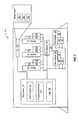
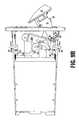
- FIG. 1is a front view of computer system employing the concepts of this invention.
- FIG. 2is a face-on isometric view of a module or assembly.
- FIG. 3is a right front isometric view of a module or assembly, with the handle in the inserted position with respect to the carrier.
- FIG. 4is an isometric view of the handle arm, hub, first and second lever arms, first and second engagement members, the cam and solenoid, without the carrier.
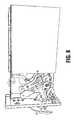
- FIG. 5is a lower right back isometric view of a module or assembly, with the handle in the inserted position.
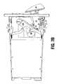
- FIG. 6is a reverse isometric view of a module or assembly, with a face of the carrier removed to reveal the component mounted inside the carrier.
- FIG. 7Ais a right back isometric view of a module or assembly, with the handle moving outward rotated less than 15 degrees from the inserted position and a surface of the cam riding on the solenoid rod, to clear the lock stop.
- FIG. 7Bis a reverse isometric view of a module or assembly, in the same state as FIG. 7 A.
- FIG. 7Cis a reverse isometric view of a module or assembly, with the handle rotated 15 degrees from the inserted position and a surface of the cam riding on the solenoid rod, having cleared the lock stop.
- FIG. 7Dis a right back isometric view of a module or assembly, with the handle rotated less than 15 degrees from the inserted position and the cam engaged with the lock stop, in its locked position.
- FIG. 8is a right back isometric view of a module or assembly, with the handle rotated 15 degrees from the inserted position and a surface of the cam riding on the solenoid rod, having cleared the lock stop.
- FIG. 9Ais a right back isometric view of a module or assembly, with the handle rotated 30 degrees from the inserted position and the cam beginning to extend through a slot in the cover.
- FIG. 9Bis a reverse isometric view of a module or assembly, in the same state as FIG. 9 a.
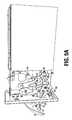
- FIG. 10Ais a right back isometric view of a module or assembly, with the handle rotated 45 degrees from the inserted position and the engagement members clearing the extraction stops.
- FIG. 10Bis a reverse isometric view of a module or assembly, in the same state as FIG. 10 a.
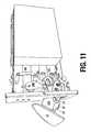
- FIG. 11is a right front isometric view of a module or assembly, with the handle moving from the extended position inward, the handle being rotated 30 degrees from the inserted position and the protrusion from the hub following the travel guide in the handle arm.
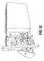
- FIG. 12is a right front isometric view of a module or assembly, with handle moving from the extended position inward, the handle being rotated 15 degrees from the inserted position and the protrusion from the hub following the travel guide in the handle arm.
- FIG. 1shows a computer system chassis 100 having a plurality of modules and a graphic user interface 160 according to the present invention.
- the computer system chassis 100has a face 145 through which components are added to and communicate with the host processing system 105 in the chassis 100 .
- the componentsare engaged to communicate with the host processor 107 in compartments accessible through corresponding slots or openings in the face 145 of the chassis 100 .
- the date processing resources in a preferredprovide storage services for a network of computers.
- the componentsinclude memory modules, such as large arrays of flash EPROMs or disk drives storing large amounts of information.
- network interface componentsare included supporting a network architecture to provide memory services to many users.
- the host system 105 in the chassis 100further include processing resources 109 associated with removing and inserting modules during operation of the host.
- the componentsare mounted in carriers that are removably mounted in compartments of the chassis 100 through the slots in the face 145 .
- Such componentsinclude controller circuit boards, disk drives, memory circuit boards and other devices having resources for communicating with the host system.
- modules 110 , 115 and 120are arranged vertically in the face 145 .
- the modules 110 , 115 and 120each include handles 111 , 116 , 121 , and respective covers as shown in more detail in FIG. 2 .
- the handles 111 , 116 , 121are engaged with a mechanism on the respective cover for locking the component within the chassis 100 when the host system is operational.
- modules 125 , 130 , 135are shown in the face 145 .
- These modulesare formed in alternative configurations, such as in a horizontal alignment relative to the chassis 100 .
- Such alternative modulesmay include disk drive arrays or other types of components designed for operation with the host system.
- the additional modules 125 , 130 and 135include handles 126 , 131 and 136 adapted for coupling with a locking mechanism and an assembly for translating motion of the handle into insertion and removal force for the component.
- GUI 160provides an interface for the operator of the device.
- the interfaceis monitored by control processes in the host system 105 for managing hot swap operations.
- the GUIincludes a module select window having graphical buttons 161 , 162 and 163 by which users are able to select modules and functions related to such modules for execution by the processes in the host system.
- logic 175 within the host system 105is coupled to the interface for managing the preparation of communication systems and power management resources for removal and insertion of components.
- the GUI 160also acts to signal the operator when the component is ready for removal, and the host system 105 is no longer overriding the lock mechanism on the component.
- the modulessuch as module 110 of the system include a component mounted within a carrier.
- the carrierincludes a structure for securing a connector for connection of the component to the system communication structure, and a mechanism for engaging and disengaging the module with the system chassis.
- a mechanical lock 185is included with the carrier which is engaged to prevent removal of the module unless the system has released the lock 185 .
- each lock 185is coupled with a respective detector 187 .
- FIG. 2is a front isometric view of an embodiment of the present invention.
- the module or assemblyis labeled 200 .
- a movable handle 201operates the engagement and disengagement mechanism of the module.
- Cover 205is on the front end of the module carrier, as depicted in subsequent figures.
- Three indicator lights 202 , 203 and 204are proximate to the module. In this embodiment, they are mounted directly on the cover of the module. In other embodiments, some or all of the indicator lights could be mounted on the chassis near the module.
- One or more of these indicator lightsare coupled to logic associated with the computer system (not shown) which controls a lock and the indicator light. This logic is able to provide an enable control signal selectively to de-actuate the lock and also a signal to enable the indicator light indicating that the module is ready to be removed.
- FIG. 3depicts a module for a computer system, also referred to as an assembly for engaging a component to a computer system.
- This moduleis adapted to fit within a compartment or slot in the chassis of a computer system.
- the carrier 300 for the module or assemblyhas a lateral edge 302 , an opposing lateral edge 304 , a front end at the cover 205 and a back end opposite the front end.
- the carrier 300has an inside where the component 306 is mounted, and an outside.
- a top guide 310 with leaf springs 312 and 313are provided, which electronically ground the module. The guide and springs fit into a slot in the chassis.
- a handle arm 320 A and 320 B, a hub 330 , a first lever arm 340 and a first engagement member 350provide means, coupled with the carrier, for an engaging and disengaging the carrier and its component with the computer system. The connections among these elements are described below.
- a handle arm 320 A and 320 Bis pivotally secured to the carrier at 321 .
- the handle arm in this embodimentincludes two flat surfaces substantially parallel to each other with a bend between the surfaces so that the two surfaces are offset.
- One extent of the handle arm 320 Aextends through a slot in cover 205 .
- the handle armhas a handle 201 attached outside the front cover. The handle arm moves from an inserted position through an intermediate position to an extended position in an arc of approximately 45 degrees.
- FIG. 3illustrates the handle in its inserted position.
- the prongs of handle 320 Bmay straddle handle arm 320 A and are rotatably coupled to the carrier 300 .
- the handle arm 320 Bdefines a travel guide, which is a cut-out in the shape of right triangle with a concave hypotenuse and rounded comers. This travel guide engages a protrusion 332 on the hub 330 which is rotatably attached to the carrier at 331 .
- a tubular rivetmay be used at 331 .
- Various approachescan be taken to prevent protrusion 332 from escaping the travel guide.
- Finger 333 of hub 330can serve as a keeper.
- a washercan be mounted on protrusion 332 so that the travel guide of arm 320 B is between hub 330 and the washer.
- one or more support bearing surfaces behind hub 330 and in front of arm 320 Bcan be used to assure that those components remain in the desired plane of rotation. In FIG.
- the hubrotates clockwise as the handle arm moves from its inserted to its extended position.
- the hubis somewhat over rotated counter-clockwise so that force applied to the hub to disengage the component tends to over-rotate the hub counter-clockwise, rather than rotating it clockwise toward disengagement.
- the hub 330is pivotally attached at 334 to a first lever arm 340 . It is also pivotally attached to a second lever arm 345 at a point not visible in this figure.
- the first and second lever armsmay pass through slots in the lateral edge 302 of the carrier and the opposing lateral edge 304 of the carrier. In FIG. 3, slot 359 in the opposing lateral edge 304 can be seen.
- the first lever arm 340is pivotally attached at 341 to a first engagement member 350 .
- the first engagement memberis pivotally attached to the carrier at fulcrum 351 , which leverages the force applied to the handle to engage the component and mate respective connectors on the component and the chassis.
- a coplaner bearing surfacemay be provided adjacent to the first and second lever arms or the first and second engagement members to assure that their movement remains in the intended plane, without twisting or torquing. Movement of the handle arm toward the inserted position rotates the hub and directs the lever arm to rotate the engagement members to engage the chassis.
- the first engagement memberis positioned with respect to the lateral edge 302 of the carrier so that it engages the chassis of the computer system when the handle arm is moved to its inserted position.
- the first engagement memberincludes a catch which engages an insertion stop 353 and an extraction stop 352 .
- the second engagement member 355also has a catch which engages a second insertion stop 358 and a second extraction stop 357 .
- FIG. 3shows that the second engagement member 355 is positioned with respect to the opposing lateral edge 304 of the carrier so it engages the chassis when the handle arm is moved to the inserted position.
- FIG. 3also shows that the second engagement member rotates through a slot 359 in opposing lateral edge 304 to engage the chassis.
- the first and second engagement membersare positioned on opposing lateral edges of the carrier so as to apply a substantially balanced force to the first and second engagement members and, thus, to the respective positions of the chains or stops on the chains which they engage.
- This embodimentalso includes a lock, comprising a cam 360 , a protrusion 362 , a spring 363 , surface on the cam 364 , a solenoid 370 , a rod (not shown) in the solenoid, and a stop (not shown).
- This lockis coupled with a detector 187 to detect movement and actuate the lock and to logic associated with the computer system to selectively override the detector and de-actuate the lock when the component is ready for removal.
- the detectormay provide a signal to actuate the lock and the logic may provide a control signal to selectively de-actuate the lock.
- the lockis coupled with the means for engaging and disengaging and is in communication with processing resources which prevent the disengagement of the carrier absent an enabled or control signal from the processing resources.
- the cam 360When the lock is in its locked position, the cam 360 engages the chassis or a stop on the chassis for resisting movement of the handle arm and removal of the component. When the lock is in its unlocked position, the cam 360 clears the chassis and stop, permitting the handle arm to move to its extended position and permitting the component to disengage from the system.
- the elements of the lockare assembled as follows: the cam 360 is pivotally coupled to the handle arm 320 A at 361 .
- a tubular rivetmay serve as a pivot axis.
- a protrusion 362 from the handle arm 320 Aengages an arc guide defined in the cam 360 .
- the arc guide in this embodimentdescribes an arc through which cam 360 pivots.
- Spring 363 mounted on the cam 360engages the protrusion 362 to bias the cam towards its locked position.
- the surface 364 of the camis adapted to engage with a rod (not shown) of the solenoid 370 .
- the solenoid rodWhen the solenoid rod is in its normal extended position, the cam surface 364 rides over the road and will clear a stop (not shown).
- the cam 360With the movement of the handle arm 320 A, the cam 360 engages the rod and assumes its unlocked position. If the solenoid 370 is actuated and the rod is in its retracted position, instead of its extended position, the cam 360 will be biased to assume its locked position and to engage with the chassis or a stop on the chassis.
- the solenoid 370is coupled to the carrier, as is the stop which cannot be seen in this figure.
- a triggerincluding a finger bearing surface (not shown) accessible by reaching under and behind handle 201 and actuated by pressing upward. Pressing the trigger rotates trigger arm 325 which includes tab 326 .
- Trigger arm 325is biased by leaf spring 323 which is mechanically coupled to the trigger arm and captured by keeper 322 .
- Tab 326engages the plunger of a two pole switch (not shown) which actuates the solenoid 370 . This switch detects movement of the handle arm. It also powers on the solenoid, which allows the solenoid to remain unpowered when the arm is in its inserted position. As the unpowered solenoid is biased in an unlocked position, the lock will not be engaged when the system is unplugged or unpowered.
- FIG. 4is a close-up isometric view of elements of this embodiment which translate movement of the handle arm 320 A into engagement of the catches on 350 and 355 with the chassis or stops on the chassis.
- the handle armis in its inserted position.
- the engagement members 350 and 355are in position to engage the chassis or stops on the chassis.
- the numbering of this figurecorresponds to FIG. 3 .
- some of the pivotal connection pointsare depicted as voids in members, rather than fulcrums, pivots, protrusions or other elements for pivotal connection the travel guide defined in the handle arm 320 B appears in an alternative configuration which is better adapted to use of a washer mounted on protrusion 322 .
- Visible in FIG. 4, but not in the previous figures,is the rod 471 of the solenoid 370 .
- the engagement of surface 364 of the cam with the rod 471 of the solenoidcan readily be seen.
- two pole switch 590 and finger bearing surface 828are visible.
- FIG. 5is a lower right back isometric view of the module or assembly, again with the handle arm in its inserted position.
- the numbering of this figurecorresponds to the numbering of previous figures.
- This figureillustrates the mounting of indicator lights 202 , 203 and 204 through the cover 205 of the chassis. The attachment of the cover with clips 306 and 307 to the chassis is clear. A few additional features not previously visible are also apparent.
- slot 509 through the cover 205is visible.
- the handle arm 320 Apasses through the slot 509 .
- the bottom guide 510 and leaf springs 512 and 513are visible.
- a connector 580appears on the outside of the carrier, at the back end. This connector is coupled to component 306 .
- This connectorincludes at least one connection element adapted to mate with a corresponding element associated with the computer system (not shown), optically mounted on the chassis upon engagement of the module.
- the connector 580may be mounted on the outside of the carrier or on the component. It is coupled with the component to provide an electrical connection between the component and the computer system.
- the location of switch 590which engages tab 326 of trigger arm 325 is apparent.
- This switchmay include a plunder biased in a first position which engages the tab 326 and is movable to a second position by the tab.
- This plungerhas a detector surface which detects engagement with tab 326 .
- FIG. 6is a reverse isometric view of the module, with the face of the carrier 300 cut away to reveal the elements mounted inside the carrier.
- connector 580 and its coupling to component 306is clear.
- the profile of hub 330is revealed in this figure.
- the pivotal connection between the hub 330 and second lever arm 345 at 635is also revealed.
- the engagement of surface 364 of the cam 360 with the rod 471can be seen.
- the over-rotation of the hub when the handle arm 320 A and 320 B is in its inserted positioncan be seen, by visualizing an axis between pivotal couplings 351 and 334 , as compared to an axis between 351 and the pivotal coupling of the hub at 331 .
- FIGS. 7A, 7 B, 7 C and 7 Dillustrate the interaction of the cam 360 and the solenoid 370 as the handle arm 320 a moves from its inserted to its extracted position.
- the numbering in these figuresis as in the previous figures.
- FIG. 7Athe handle 201 and the handle arm 320 A have been pulled out less than 15 degrees from their inserted position to an intermediate position.
- the rod 471 (not shown) of the solenoid 370is in its normal extended position, as the cam 360 is rotated in opposition to the biasing spring 363 and is in the unlocked position where it will clear stop 575 .
- the camis rotated because surface 364 is riding on the rod.
- FIG. 7Bis a reverse isometric view with handle 201 in the same position as in FIG.
- FIG. 7Aillustrates handle 201 and handle arm 320 A rotated 15 degrees from their inserted position to an intermediate position. The contact between surface 364 and rod 471 is again apparent.
- FIGS. 7A, 7 B and 7 Cthe cam 360 is in an unlocked position.
- FIG. 7Dshows the cam in its locked position. Rod 471 , not visible in FIG. 7D, must be retracted, as cam 360 is securely engaged against stop 575 .
- FIG. 8illustrates the handle 201 and handle arm 320 A and 320 B rotated 15 degrees from the inserted position. This 15 degree rotation is approximately the extent of free travel of the handle arm before the travel guide engages protrusions 332 and begins to rotate hub 330 .
- This figureshows that the lever arm and hub are still in their over-rotated position.
- the protrusion 332has begun to engage the travel guide defined by handle arm 320 B. Additional rotation will cause the travel guide to apply force to the protrusion, thereby tending to rotate the hub clockwise toward a disengage position.
- Finger bearing surface 828coupled to trigger arm 325 , is revealed in this figure and is easily seen in FIG. 9 A.
- FIGS. 9A and 9Bare isometric and reverse isometric views of this translation mechanism, with the handle 201 and handle arm 320 A rotated 30 degrees from the inserted position. These figures demonstrate that force applied by the travel guide defined in handle arm 320 B to the protrusion 332 translates movement of the handle arm into rotation of the hub, which causes movement of the lever arms and rotation of the engagement members. Movement of the handle arm from the intermediate position to the extended position causes force to be applied by the catches of the first engagement arm 350 and the second engagement arm 355 to the chassis or to insertion stops 353 and 358 , promoting disengagement of the module from chassis.
- FIGS. 10A and 10Bare isometric and reverse isometric views of this translation mechanism with the handle 201 and handle arm 320 a rotated 45 degrees to the extended position.
- FIG. 11depicts this embodiment of the translation mechanism when the handle 201 and handle arm 320 A are being pushed from their extended position to an intermediate position. Due to the shape of the travel guide defined in handle arm 320 B, this embodiment of the present invention reacts differently when the handle arm is at 30 degrees on a path toward its inserted position than it does when the handle arm is at 30 degrees on a path toward its extended position. As the handle is pushed in, at 30 degrees the protrusion 332 engages the side of the travel guide proximal to the front end of the carrier. The travel guide applies force to the hub, causing it to rotate the toward its engaged position.
- FIG. 12shows the translation mechanism as the handle 201 and handle arm 320 A reach an angle of 15 degrees, on a path from an intermediate position toward the inserted position.
- the hubis approaching its over-rotated, inserted and engaged position.
- the protrusion 332has nearly reached the end of its travel along the edge of the travel guide proximal to the front end of the carrier.
- the embodiments shownare advantageous for reasons including:
- the solenoidis powered from the chassis through a connection to the module.
- Non-operating (de-energized) boardsmay be removed at any time.
- a switch on the release latchalerts the system when a board is being unplugged.
- the second pole of the switchcontrols power to solenoid, avoiding the delay otherwise resulting from software control.
- the solenoidonly operates when the release latch is squeezed. No force is applied to the solenoid when the module is locked and a user attempts to remove the module. Only a small force is applied to the solenoid when the system is unlocked. This allows the use of a very small solenoid.
- the indicator lightdirects the user to the module being removed.
- the graphical user interfaceassists the user in requesting removal of a component.
- the amount of resistance to removalgives the user a tactile indication of whether the component is ready for removal.
Landscapes
- Engineering & Computer Science (AREA)
- Theoretical Computer Science (AREA)
- Physics & Mathematics (AREA)
- General Engineering & Computer Science (AREA)
- General Physics & Mathematics (AREA)
- Quality & Reliability (AREA)
- Computer Hardware Design (AREA)
- Power Engineering (AREA)
- Human Computer Interaction (AREA)
- Mounting Of Printed Circuit Boards And The Like (AREA)
Abstract
Description
Claims (50)
Priority Applications (1)
| Application Number | Priority Date | Filing Date | Title |
|---|---|---|---|
| US09/572,149US6774808B1 (en) | 2000-05-17 | 2000-05-17 | Electromechanical lock for components |
Applications Claiming Priority (1)
| Application Number | Priority Date | Filing Date | Title |
|---|---|---|---|
| US09/572,149US6774808B1 (en) | 2000-05-17 | 2000-05-17 | Electromechanical lock for components |
Publications (1)
| Publication Number | Publication Date |
|---|---|
| US6774808B1true US6774808B1 (en) | 2004-08-10 |
Family
ID=32825591
Family Applications (1)
| Application Number | Title | Priority Date | Filing Date |
|---|---|---|---|
| US09/572,149Expired - LifetimeUS6774808B1 (en) | 2000-05-17 | 2000-05-17 | Electromechanical lock for components |
Country Status (1)
| Country | Link |
|---|---|
| US (1) | US6774808B1 (en) |
Cited By (88)
| Publication number | Priority date | Publication date | Assignee | Title |
|---|---|---|---|---|
| US20050030721A1 (en)* | 2002-08-09 | 2005-02-10 | Tsutomu Shimada | Electronic apparatus and information processing apparatus |
| US20060002093A1 (en)* | 2004-07-02 | 2006-01-05 | Seagate Technology Llc | Engagement system for a module in an electronics cabinet |
| US20060150206A1 (en)* | 2004-12-30 | 2006-07-06 | Hon Hai Precision Industry Co., Ltd. | Mounting apparatus for data storage device |
| US20070217142A1 (en)* | 2006-03-20 | 2007-09-20 | Takeshi Wagatsuma | Hard disk enclosure blade |
| US20080126686A1 (en)* | 2006-11-28 | 2008-05-29 | Anobit Technologies Ltd. | Memory power and performance management |
| US20080181001A1 (en)* | 2007-01-24 | 2008-07-31 | Anobit Technologies | Memory device with negative thresholds |
| US20080198650A1 (en)* | 2006-05-12 | 2008-08-21 | Anobit Technologies Ltd. | Distortion Estimation And Cancellation In Memory Devices |
| CN100426186C (en)* | 2005-10-20 | 2008-10-15 | 微星科技股份有限公司 | Bearing base frame |
| US20090091979A1 (en)* | 2007-10-08 | 2009-04-09 | Anobit Technologies | Reliable data storage in analog memory cells in the presence of temperature variations |
| US20090213654A1 (en)* | 2008-02-24 | 2009-08-27 | Anobit Technologies Ltd | Programming analog memory cells for reduced variance after retention |
| US20090230279A1 (en)* | 2008-03-14 | 2009-09-17 | Southco, Inc. | Leverage Device and System Using Same |
| US20100033927A1 (en)* | 2008-08-05 | 2010-02-11 | Japan Aviation Electronics Industry, Limited | Eject mechanism and electrical apparatus comprising the same |
| US20100110787A1 (en)* | 2006-10-30 | 2010-05-06 | Anobit Technologies Ltd. | Memory cell readout using successive approximation |
| US20100131826A1 (en)* | 2006-08-27 | 2010-05-27 | Anobit Technologies Ltd. | Estimation of non-linear distortion in memory devices |
| US20100165730A1 (en)* | 2006-10-30 | 2010-07-01 | Anobit Technologies Ltd. | Reading memory cells using multiple thresholds |
| US7900102B2 (en) | 2006-12-17 | 2011-03-01 | Anobit Technologies Ltd. | High-speed programming of memory devices |
| US7924587B2 (en) | 2008-02-21 | 2011-04-12 | Anobit Technologies Ltd. | Programming of analog memory cells using a single programming pulse per state transition |
| US7925936B1 (en) | 2007-07-13 | 2011-04-12 | Anobit Technologies Ltd. | Memory device with non-uniform programming levels |
| US7924613B1 (en) | 2008-08-05 | 2011-04-12 | Anobit Technologies Ltd. | Data storage in analog memory cells with protection against programming interruption |
| US20110095153A1 (en)* | 2009-10-22 | 2011-04-28 | Hong Fu Jin Precision Industry (Shenzhen) Co., Ltd. | Mounting apparatus for data storage device |
| US7995388B1 (en) | 2008-08-05 | 2011-08-09 | Anobit Technologies Ltd. | Data storage using modified voltages |
| US8000135B1 (en) | 2008-09-14 | 2011-08-16 | Anobit Technologies Ltd. | Estimation of memory cell read thresholds by sampling inside programming level distribution intervals |
| US8001320B2 (en) | 2007-04-22 | 2011-08-16 | Anobit Technologies Ltd. | Command interface for memory devices |
| US8000141B1 (en) | 2007-10-19 | 2011-08-16 | Anobit Technologies Ltd. | Compensation for voltage drifts in analog memory cells |
| US8059457B2 (en) | 2008-03-18 | 2011-11-15 | Anobit Technologies Ltd. | Memory device with multiple-accuracy read commands |
| US8068360B2 (en) | 2007-10-19 | 2011-11-29 | Anobit Technologies Ltd. | Reading analog memory cells using built-in multi-threshold commands |
| US8085586B2 (en) | 2007-12-27 | 2011-12-27 | Anobit Technologies Ltd. | Wear level estimation in analog memory cells |
| US8130490B2 (en)* | 2007-08-06 | 2012-03-06 | Wistron Corporation | Detachable hard drive with an electromagnetic switch |
| US8151166B2 (en) | 2007-01-24 | 2012-04-03 | Anobit Technologies Ltd. | Reduction of back pattern dependency effects in memory devices |
| US8151163B2 (en) | 2006-12-03 | 2012-04-03 | Anobit Technologies Ltd. | Automatic defect management in memory devices |
| US8156398B2 (en) | 2008-02-05 | 2012-04-10 | Anobit Technologies Ltd. | Parameter estimation based on error correction code parity check equations |
| US8156403B2 (en) | 2006-05-12 | 2012-04-10 | Anobit Technologies Ltd. | Combined distortion estimation and error correction coding for memory devices |
| US8154862B2 (en)* | 2010-08-30 | 2012-04-10 | Ping-Hung Lai | Open external hard drive enclosure |
| US8169825B1 (en) | 2008-09-02 | 2012-05-01 | Anobit Technologies Ltd. | Reliable data storage in analog memory cells subjected to long retention periods |
| US8174857B1 (en) | 2008-12-31 | 2012-05-08 | Anobit Technologies Ltd. | Efficient readout schemes for analog memory cell devices using multiple read threshold sets |
| US8174905B2 (en) | 2007-09-19 | 2012-05-08 | Anobit Technologies Ltd. | Programming orders for reducing distortion in arrays of multi-level analog memory cells |
| US20120120587A1 (en)* | 2010-11-11 | 2012-05-17 | Dell Products L.P. | Latching module mounting system |
| US8208304B2 (en) | 2008-11-16 | 2012-06-26 | Anobit Technologies Ltd. | Storage at M bits/cell density in N bits/cell analog memory cell devices, M>N |
| US8209588B2 (en) | 2007-12-12 | 2012-06-26 | Anobit Technologies Ltd. | Efficient interference cancellation in analog memory cell arrays |
| US8225181B2 (en) | 2007-11-30 | 2012-07-17 | Apple Inc. | Efficient re-read operations from memory devices |
| US8228701B2 (en) | 2009-03-01 | 2012-07-24 | Apple Inc. | Selective activation of programming schemes in analog memory cell arrays |
| US8230300B2 (en) | 2008-03-07 | 2012-07-24 | Apple Inc. | Efficient readout from analog memory cells using data compression |
| US8234545B2 (en) | 2007-05-12 | 2012-07-31 | Apple Inc. | Data storage with incremental redundancy |
| US8238157B1 (en) | 2009-04-12 | 2012-08-07 | Apple Inc. | Selective re-programming of analog memory cells |
| US8239734B1 (en) | 2008-10-15 | 2012-08-07 | Apple Inc. | Efficient data storage in storage device arrays |
| US8239735B2 (en) | 2006-05-12 | 2012-08-07 | Apple Inc. | Memory Device with adaptive capacity |
| US8248831B2 (en) | 2008-12-31 | 2012-08-21 | Apple Inc. | Rejuvenation of analog memory cells |
| US8261159B1 (en) | 2008-10-30 | 2012-09-04 | Apple, Inc. | Data scrambling schemes for memory devices |
| US8259497B2 (en) | 2007-08-06 | 2012-09-04 | Apple Inc. | Programming schemes for multi-level analog memory cells |
| US8259506B1 (en) | 2009-03-25 | 2012-09-04 | Apple Inc. | Database of memory read thresholds |
| US8270246B2 (en) | 2007-11-13 | 2012-09-18 | Apple Inc. | Optimized selection of memory chips in multi-chips memory devices |
| US8369141B2 (en) | 2007-03-12 | 2013-02-05 | Apple Inc. | Adaptive estimation of memory cell read thresholds |
| US8400858B2 (en) | 2008-03-18 | 2013-03-19 | Apple Inc. | Memory device with reduced sense time readout |
| US8429493B2 (en) | 2007-05-12 | 2013-04-23 | Apple Inc. | Memory device with internal signap processing unit |
| US8456905B2 (en) | 2007-12-16 | 2013-06-04 | Apple Inc. | Efficient data storage in multi-plane memory devices |
| US20130154288A1 (en)* | 2010-10-22 | 2013-06-20 | Yi-Feng Lin | Handle module |
| US20130163184A1 (en)* | 2011-12-21 | 2013-06-27 | Sony Corporation | Electronic apparatus |
| US8479080B1 (en) | 2009-07-12 | 2013-07-02 | Apple Inc. | Adaptive over-provisioning in memory systems |
| US8482978B1 (en) | 2008-09-14 | 2013-07-09 | Apple Inc. | Estimation of memory cell read thresholds by sampling inside programming level distribution intervals |
| US8495465B1 (en) | 2009-10-15 | 2013-07-23 | Apple Inc. | Error correction coding over multiple memory pages |
| US8527819B2 (en) | 2007-10-19 | 2013-09-03 | Apple Inc. | Data storage in analog memory cell arrays having erase failures |
| US8572423B1 (en) | 2010-06-22 | 2013-10-29 | Apple Inc. | Reducing peak current in memory systems |
| US8572311B1 (en) | 2010-01-11 | 2013-10-29 | Apple Inc. | Redundant data storage in multi-die memory systems |
| US8595591B1 (en) | 2010-07-11 | 2013-11-26 | Apple Inc. | Interference-aware assignment of programming levels in analog memory cells |
| US8645794B1 (en) | 2010-07-31 | 2014-02-04 | Apple Inc. | Data storage in analog memory cells using a non-integer number of bits per cell |
| US8677054B1 (en) | 2009-12-16 | 2014-03-18 | Apple Inc. | Memory management schemes for non-volatile memory devices |
| US8694854B1 (en) | 2010-08-17 | 2014-04-08 | Apple Inc. | Read threshold setting based on soft readout statistics |
| US8694853B1 (en) | 2010-05-04 | 2014-04-08 | Apple Inc. | Read commands for reading interfering memory cells |
| US8694814B1 (en) | 2010-01-10 | 2014-04-08 | Apple Inc. | Reuse of host hibernation storage space by memory controller |
| US8832354B2 (en) | 2009-03-25 | 2014-09-09 | Apple Inc. | Use of host system resources by memory controller |
| US8856475B1 (en) | 2010-08-01 | 2014-10-07 | Apple Inc. | Efficient selection of memory blocks for compaction |
| US20140331009A1 (en)* | 2013-05-01 | 2014-11-06 | International Business Machines Corporation | Selectively securing a hot-swappable data storage device to prevent data corruption |
| US8924661B1 (en) | 2009-01-18 | 2014-12-30 | Apple Inc. | Memory system including a controller and processors associated with memory devices |
| US8919210B2 (en)* | 2012-11-27 | 2014-12-30 | Life Technologies Corporation | Load cell lockouts and related fluid dispensing systems |
| US8949684B1 (en) | 2008-09-02 | 2015-02-03 | Apple Inc. | Segmented data storage |
| US9021181B1 (en) | 2010-09-27 | 2015-04-28 | Apple Inc. | Memory management for unifying memory cell conditions by using maximum time intervals |
| US9104580B1 (en) | 2010-07-27 | 2015-08-11 | Apple Inc. | Cache memory for hybrid disk drives |
| US20160179131A1 (en)* | 2014-12-18 | 2016-06-23 | Quanta Computer Inc. | Systems and methods for mounting and dismounting computing components |
| US9830952B1 (en)* | 2016-11-03 | 2017-11-28 | International Business Machines Corporation | Preventing physical removal of a drive with a medium in motion for mitigating damage events to components of the drive |
| US9841790B2 (en)* | 2016-04-07 | 2017-12-12 | Dell Products L.P. | Lever release mechanism for a computer component |
| US9947371B1 (en)* | 2017-01-23 | 2018-04-17 | Quanta Computer Inc. | Compact tool-less HDD carrier |
| US20180160563A1 (en)* | 2016-12-07 | 2018-06-07 | Dell Products L.P. | Lever release mechanism for information handling system chassis sled |
| US10133315B2 (en)* | 2016-11-08 | 2018-11-20 | Microsoft Technology Licensing, Llc | Indexed sequential lock |
| US10664024B2 (en)* | 2017-10-05 | 2020-05-26 | Dell Products, L.P. | Hard drive carrier with a handle that is rotatable between an open position and a closed position to engage a sled of an information handling system |
| US10939573B1 (en)* | 2019-08-28 | 2021-03-02 | Dell Products, L.P. | Electronic module carrier for an information handling system |
| US11314293B1 (en)* | 2020-11-09 | 2022-04-26 | ZT Group Int'l, Inc. | Latch for device with ruler profile |
| US11556416B2 (en) | 2021-05-05 | 2023-01-17 | Apple Inc. | Controlling memory readout reliability and throughput by adjusting distance between read thresholds |
| US11847342B2 (en) | 2021-07-28 | 2023-12-19 | Apple Inc. | Efficient transfer of hard data and confidence levels in reading a nonvolatile memory |
Citations (14)
| Publication number | Priority date | Publication date | Assignee | Title |
|---|---|---|---|---|
| US4656848A (en)* | 1984-08-27 | 1987-04-14 | Rose C David | Security device for personal computers |
| US4925397A (en)* | 1989-07-24 | 1990-05-15 | American International Devices, Inc. | Latch mechanism for computer module |
| US5442513A (en)* | 1994-02-18 | 1995-08-15 | Lo; Hsin Y. | Hard disk drive and casing slidably received within frame having double-swinging door and lock |
| US5483419A (en)* | 1991-09-24 | 1996-01-09 | Teac Corporation | Hot-swappable multi-cartridge docking module |
| US5509731A (en)* | 1993-10-18 | 1996-04-23 | Microplas, Inc. | Ejecting storage case |
| US5557499A (en)* | 1994-06-28 | 1996-09-17 | Ast Research, Inc. | Hard-disk drive tray assembly with pivotally rotatable front bezel |
| US5600539A (en)* | 1994-10-11 | 1997-02-04 | At&T Global Information Solutions Company | Secure interface card extractor/ejector mechanism |
| US5692208A (en)* | 1995-04-07 | 1997-11-25 | Compaq Computer Corporation | Lever apparatus for an ejector mechanism in a personal computer |
| US5751551A (en)* | 1995-11-07 | 1998-05-12 | Sun Microsystems, Inc. | Universal hard drive bracket with shock and vibrational isolation and electrical grounding |
| US5791753A (en)* | 1996-08-29 | 1998-08-11 | Compaq Computer Corp. | Computer component handle assembly |
| US5831821A (en)* | 1997-01-24 | 1998-11-03 | Dell Computer Corporation | Computer having an expansion card cage assembly |
| US5857364A (en)* | 1997-05-27 | 1999-01-12 | Digital Equipment Corporation | Two-way lock mechanism with cam action |
| US5914855A (en)* | 1997-12-30 | 1999-06-22 | International Business Machines Corporation | Apparatus and method for damping disk drive vibration |
| US6252514B1 (en)* | 1999-06-07 | 2001-06-26 | Convergent Technologies, Inc. | Hot-swap assembly for computers |
- 2000
- 2000-05-17USUS09/572,149patent/US6774808B1/ennot_activeExpired - Lifetime
Patent Citations (14)
| Publication number | Priority date | Publication date | Assignee | Title |
|---|---|---|---|---|
| US4656848A (en)* | 1984-08-27 | 1987-04-14 | Rose C David | Security device for personal computers |
| US4925397A (en)* | 1989-07-24 | 1990-05-15 | American International Devices, Inc. | Latch mechanism for computer module |
| US5483419A (en)* | 1991-09-24 | 1996-01-09 | Teac Corporation | Hot-swappable multi-cartridge docking module |
| US5509731A (en)* | 1993-10-18 | 1996-04-23 | Microplas, Inc. | Ejecting storage case |
| US5442513A (en)* | 1994-02-18 | 1995-08-15 | Lo; Hsin Y. | Hard disk drive and casing slidably received within frame having double-swinging door and lock |
| US5557499A (en)* | 1994-06-28 | 1996-09-17 | Ast Research, Inc. | Hard-disk drive tray assembly with pivotally rotatable front bezel |
| US5600539A (en)* | 1994-10-11 | 1997-02-04 | At&T Global Information Solutions Company | Secure interface card extractor/ejector mechanism |
| US5692208A (en)* | 1995-04-07 | 1997-11-25 | Compaq Computer Corporation | Lever apparatus for an ejector mechanism in a personal computer |
| US5751551A (en)* | 1995-11-07 | 1998-05-12 | Sun Microsystems, Inc. | Universal hard drive bracket with shock and vibrational isolation and electrical grounding |
| US5791753A (en)* | 1996-08-29 | 1998-08-11 | Compaq Computer Corp. | Computer component handle assembly |
| US5831821A (en)* | 1997-01-24 | 1998-11-03 | Dell Computer Corporation | Computer having an expansion card cage assembly |
| US5857364A (en)* | 1997-05-27 | 1999-01-12 | Digital Equipment Corporation | Two-way lock mechanism with cam action |
| US5914855A (en)* | 1997-12-30 | 1999-06-22 | International Business Machines Corporation | Apparatus and method for damping disk drive vibration |
| US6252514B1 (en)* | 1999-06-07 | 2001-06-26 | Convergent Technologies, Inc. | Hot-swap assembly for computers |
Cited By (124)
| Publication number | Priority date | Publication date | Assignee | Title |
|---|---|---|---|---|
| US20050030721A1 (en)* | 2002-08-09 | 2005-02-10 | Tsutomu Shimada | Electronic apparatus and information processing apparatus |
| US6992897B2 (en)* | 2002-08-09 | 2006-01-31 | Canon Kabushiki Kaisha | Electronic apparatus and information processing apparatus |
| US20060067061A1 (en)* | 2002-08-09 | 2006-03-30 | Canon Kabushiki Kaisha | Electronic apparatus and information processing apparatus |
| US7170743B2 (en) | 2002-08-09 | 2007-01-30 | Canon Kabushiki Kaisha | Electronic apparatus and information processing apparatus |
| US20060002093A1 (en)* | 2004-07-02 | 2006-01-05 | Seagate Technology Llc | Engagement system for a module in an electronics cabinet |
| US7327564B2 (en)* | 2004-07-02 | 2008-02-05 | Seagate Technology Llc | Engagement system for a module in an electronics cabinet |
| US20060150206A1 (en)* | 2004-12-30 | 2006-07-06 | Hon Hai Precision Industry Co., Ltd. | Mounting apparatus for data storage device |
| US7483266B2 (en)* | 2004-12-30 | 2009-01-27 | Hong Fu Jin Precision Industry (Shenzhen) Co., Ltd. | Mounting apparatus for data storage device |
| CN100426186C (en)* | 2005-10-20 | 2008-10-15 | 微星科技股份有限公司 | Bearing base frame |
| US20070217142A1 (en)* | 2006-03-20 | 2007-09-20 | Takeshi Wagatsuma | Hard disk enclosure blade |
| US20070217143A1 (en)* | 2006-03-20 | 2007-09-20 | International Business Machines Corporation | Hard disk enclosure blade |
| US7499271B2 (en)* | 2006-03-20 | 2009-03-03 | International Business Machines Corporation | Hard disk enclosure blade |
| US8156403B2 (en) | 2006-05-12 | 2012-04-10 | Anobit Technologies Ltd. | Combined distortion estimation and error correction coding for memory devices |
| US20080198650A1 (en)* | 2006-05-12 | 2008-08-21 | Anobit Technologies Ltd. | Distortion Estimation And Cancellation In Memory Devices |
| US8570804B2 (en) | 2006-05-12 | 2013-10-29 | Apple Inc. | Distortion estimation and cancellation in memory devices |
| US8239735B2 (en) | 2006-05-12 | 2012-08-07 | Apple Inc. | Memory Device with adaptive capacity |
| US8599611B2 (en) | 2006-05-12 | 2013-12-03 | Apple Inc. | Distortion estimation and cancellation in memory devices |
| US8050086B2 (en) | 2006-05-12 | 2011-11-01 | Anobit Technologies Ltd. | Distortion estimation and cancellation in memory devices |
| US20100131826A1 (en)* | 2006-08-27 | 2010-05-27 | Anobit Technologies Ltd. | Estimation of non-linear distortion in memory devices |
| US8060806B2 (en) | 2006-08-27 | 2011-11-15 | Anobit Technologies Ltd. | Estimation of non-linear distortion in memory devices |
| US20100110787A1 (en)* | 2006-10-30 | 2010-05-06 | Anobit Technologies Ltd. | Memory cell readout using successive approximation |
| US20100165730A1 (en)* | 2006-10-30 | 2010-07-01 | Anobit Technologies Ltd. | Reading memory cells using multiple thresholds |
| US7975192B2 (en) | 2006-10-30 | 2011-07-05 | Anobit Technologies Ltd. | Reading memory cells using multiple thresholds |
| USRE46346E1 (en) | 2006-10-30 | 2017-03-21 | Apple Inc. | Reading memory cells using multiple thresholds |
| US7821826B2 (en) | 2006-10-30 | 2010-10-26 | Anobit Technologies, Ltd. | Memory cell readout using successive approximation |
| US8145984B2 (en) | 2006-10-30 | 2012-03-27 | Anobit Technologies Ltd. | Reading memory cells using multiple thresholds |
| US20080126686A1 (en)* | 2006-11-28 | 2008-05-29 | Anobit Technologies Ltd. | Memory power and performance management |
| US7924648B2 (en) | 2006-11-28 | 2011-04-12 | Anobit Technologies Ltd. | Memory power and performance management |
| US8151163B2 (en) | 2006-12-03 | 2012-04-03 | Anobit Technologies Ltd. | Automatic defect management in memory devices |
| US7900102B2 (en) | 2006-12-17 | 2011-03-01 | Anobit Technologies Ltd. | High-speed programming of memory devices |
| US7881107B2 (en) | 2007-01-24 | 2011-02-01 | Anobit Technologies Ltd. | Memory device with negative thresholds |
| US8151166B2 (en) | 2007-01-24 | 2012-04-03 | Anobit Technologies Ltd. | Reduction of back pattern dependency effects in memory devices |
| US7751240B2 (en) | 2007-01-24 | 2010-07-06 | Anobit Technologies Ltd. | Memory device with negative thresholds |
| US20080181001A1 (en)* | 2007-01-24 | 2008-07-31 | Anobit Technologies | Memory device with negative thresholds |
| US8369141B2 (en) | 2007-03-12 | 2013-02-05 | Apple Inc. | Adaptive estimation of memory cell read thresholds |
| US8001320B2 (en) | 2007-04-22 | 2011-08-16 | Anobit Technologies Ltd. | Command interface for memory devices |
| US8429493B2 (en) | 2007-05-12 | 2013-04-23 | Apple Inc. | Memory device with internal signap processing unit |
| US8234545B2 (en) | 2007-05-12 | 2012-07-31 | Apple Inc. | Data storage with incremental redundancy |
| US7925936B1 (en) | 2007-07-13 | 2011-04-12 | Anobit Technologies Ltd. | Memory device with non-uniform programming levels |
| US8130490B2 (en)* | 2007-08-06 | 2012-03-06 | Wistron Corporation | Detachable hard drive with an electromagnetic switch |
| US8259497B2 (en) | 2007-08-06 | 2012-09-04 | Apple Inc. | Programming schemes for multi-level analog memory cells |
| US8174905B2 (en) | 2007-09-19 | 2012-05-08 | Anobit Technologies Ltd. | Programming orders for reducing distortion in arrays of multi-level analog memory cells |
| US20090091979A1 (en)* | 2007-10-08 | 2009-04-09 | Anobit Technologies | Reliable data storage in analog memory cells in the presence of temperature variations |
| US7773413B2 (en) | 2007-10-08 | 2010-08-10 | Anobit Technologies Ltd. | Reliable data storage in analog memory cells in the presence of temperature variations |
| US8068360B2 (en) | 2007-10-19 | 2011-11-29 | Anobit Technologies Ltd. | Reading analog memory cells using built-in multi-threshold commands |
| US8000141B1 (en) | 2007-10-19 | 2011-08-16 | Anobit Technologies Ltd. | Compensation for voltage drifts in analog memory cells |
| US8527819B2 (en) | 2007-10-19 | 2013-09-03 | Apple Inc. | Data storage in analog memory cell arrays having erase failures |
| US8270246B2 (en) | 2007-11-13 | 2012-09-18 | Apple Inc. | Optimized selection of memory chips in multi-chips memory devices |
| US8225181B2 (en) | 2007-11-30 | 2012-07-17 | Apple Inc. | Efficient re-read operations from memory devices |
| US8209588B2 (en) | 2007-12-12 | 2012-06-26 | Anobit Technologies Ltd. | Efficient interference cancellation in analog memory cell arrays |
| US8456905B2 (en) | 2007-12-16 | 2013-06-04 | Apple Inc. | Efficient data storage in multi-plane memory devices |
| US8085586B2 (en) | 2007-12-27 | 2011-12-27 | Anobit Technologies Ltd. | Wear level estimation in analog memory cells |
| US8156398B2 (en) | 2008-02-05 | 2012-04-10 | Anobit Technologies Ltd. | Parameter estimation based on error correction code parity check equations |
| US7924587B2 (en) | 2008-02-21 | 2011-04-12 | Anobit Technologies Ltd. | Programming of analog memory cells using a single programming pulse per state transition |
| US20090213654A1 (en)* | 2008-02-24 | 2009-08-27 | Anobit Technologies Ltd | Programming analog memory cells for reduced variance after retention |
| US7864573B2 (en) | 2008-02-24 | 2011-01-04 | Anobit Technologies Ltd. | Programming analog memory cells for reduced variance after retention |
| US8230300B2 (en) | 2008-03-07 | 2012-07-24 | Apple Inc. | Efficient readout from analog memory cells using data compression |
| US20090230279A1 (en)* | 2008-03-14 | 2009-09-17 | Southco, Inc. | Leverage Device and System Using Same |
| US8256737B2 (en)* | 2008-03-14 | 2012-09-04 | Southco, Inc. | Leverage device and system using same |
| US8059457B2 (en) | 2008-03-18 | 2011-11-15 | Anobit Technologies Ltd. | Memory device with multiple-accuracy read commands |
| US8400858B2 (en) | 2008-03-18 | 2013-03-19 | Apple Inc. | Memory device with reduced sense time readout |
| US8498151B1 (en) | 2008-08-05 | 2013-07-30 | Apple Inc. | Data storage in analog memory cells using modified pass voltages |
| US7995388B1 (en) | 2008-08-05 | 2011-08-09 | Anobit Technologies Ltd. | Data storage using modified voltages |
| US7924613B1 (en) | 2008-08-05 | 2011-04-12 | Anobit Technologies Ltd. | Data storage in analog memory cells with protection against programming interruption |
| US20100033927A1 (en)* | 2008-08-05 | 2010-02-11 | Japan Aviation Electronics Industry, Limited | Eject mechanism and electrical apparatus comprising the same |
| US8169825B1 (en) | 2008-09-02 | 2012-05-01 | Anobit Technologies Ltd. | Reliable data storage in analog memory cells subjected to long retention periods |
| US8949684B1 (en) | 2008-09-02 | 2015-02-03 | Apple Inc. | Segmented data storage |
| US8482978B1 (en) | 2008-09-14 | 2013-07-09 | Apple Inc. | Estimation of memory cell read thresholds by sampling inside programming level distribution intervals |
| US8000135B1 (en) | 2008-09-14 | 2011-08-16 | Anobit Technologies Ltd. | Estimation of memory cell read thresholds by sampling inside programming level distribution intervals |
| US8239734B1 (en) | 2008-10-15 | 2012-08-07 | Apple Inc. | Efficient data storage in storage device arrays |
| US8261159B1 (en) | 2008-10-30 | 2012-09-04 | Apple, Inc. | Data scrambling schemes for memory devices |
| US8713330B1 (en) | 2008-10-30 | 2014-04-29 | Apple Inc. | Data scrambling in memory devices |
| US8208304B2 (en) | 2008-11-16 | 2012-06-26 | Anobit Technologies Ltd. | Storage at M bits/cell density in N bits/cell analog memory cell devices, M>N |
| US8397131B1 (en) | 2008-12-31 | 2013-03-12 | Apple Inc. | Efficient readout schemes for analog memory cell devices |
| US8248831B2 (en) | 2008-12-31 | 2012-08-21 | Apple Inc. | Rejuvenation of analog memory cells |
| US8174857B1 (en) | 2008-12-31 | 2012-05-08 | Anobit Technologies Ltd. | Efficient readout schemes for analog memory cell devices using multiple read threshold sets |
| US8924661B1 (en) | 2009-01-18 | 2014-12-30 | Apple Inc. | Memory system including a controller and processors associated with memory devices |
| US8228701B2 (en) | 2009-03-01 | 2012-07-24 | Apple Inc. | Selective activation of programming schemes in analog memory cell arrays |
| US8259506B1 (en) | 2009-03-25 | 2012-09-04 | Apple Inc. | Database of memory read thresholds |
| US8832354B2 (en) | 2009-03-25 | 2014-09-09 | Apple Inc. | Use of host system resources by memory controller |
| US8238157B1 (en) | 2009-04-12 | 2012-08-07 | Apple Inc. | Selective re-programming of analog memory cells |
| US8479080B1 (en) | 2009-07-12 | 2013-07-02 | Apple Inc. | Adaptive over-provisioning in memory systems |
| US8495465B1 (en) | 2009-10-15 | 2013-07-23 | Apple Inc. | Error correction coding over multiple memory pages |
| EP2315210A3 (en)* | 2009-10-22 | 2011-06-15 | Hong Fu Jin Precision Industry (ShenZhen) Co. Ltd. | Mounting apparatus for data storage device |
| US20110095153A1 (en)* | 2009-10-22 | 2011-04-28 | Hong Fu Jin Precision Industry (Shenzhen) Co., Ltd. | Mounting apparatus for data storage device |
| US8248775B2 (en) | 2009-10-22 | 2012-08-21 | Hong Fu Jin Precision Industry (Shenzhen) Co., Ltd. | Mounting apparatus with pivotable latch member to lock data storage device |
| US8677054B1 (en) | 2009-12-16 | 2014-03-18 | Apple Inc. | Memory management schemes for non-volatile memory devices |
| US8694814B1 (en) | 2010-01-10 | 2014-04-08 | Apple Inc. | Reuse of host hibernation storage space by memory controller |
| US8677203B1 (en) | 2010-01-11 | 2014-03-18 | Apple Inc. | Redundant data storage schemes for multi-die memory systems |
| US8572311B1 (en) | 2010-01-11 | 2013-10-29 | Apple Inc. | Redundant data storage in multi-die memory systems |
| US8694853B1 (en) | 2010-05-04 | 2014-04-08 | Apple Inc. | Read commands for reading interfering memory cells |
| US8572423B1 (en) | 2010-06-22 | 2013-10-29 | Apple Inc. | Reducing peak current in memory systems |
| US8595591B1 (en) | 2010-07-11 | 2013-11-26 | Apple Inc. | Interference-aware assignment of programming levels in analog memory cells |
| US9104580B1 (en) | 2010-07-27 | 2015-08-11 | Apple Inc. | Cache memory for hybrid disk drives |
| US8767459B1 (en) | 2010-07-31 | 2014-07-01 | Apple Inc. | Data storage in analog memory cells across word lines using a non-integer number of bits per cell |
| US8645794B1 (en) | 2010-07-31 | 2014-02-04 | Apple Inc. | Data storage in analog memory cells using a non-integer number of bits per cell |
| US8856475B1 (en) | 2010-08-01 | 2014-10-07 | Apple Inc. | Efficient selection of memory blocks for compaction |
| US8694854B1 (en) | 2010-08-17 | 2014-04-08 | Apple Inc. | Read threshold setting based on soft readout statistics |
| US8154862B2 (en)* | 2010-08-30 | 2012-04-10 | Ping-Hung Lai | Open external hard drive enclosure |
| US9021181B1 (en) | 2010-09-27 | 2015-04-28 | Apple Inc. | Memory management for unifying memory cell conditions by using maximum time intervals |
| US10101766B2 (en)* | 2010-10-22 | 2018-10-16 | Hewlett-Packard Development Company, L.P. | Handle module |
| US20130154288A1 (en)* | 2010-10-22 | 2013-06-20 | Yi-Feng Lin | Handle module |
| US20120120587A1 (en)* | 2010-11-11 | 2012-05-17 | Dell Products L.P. | Latching module mounting system |
| US8437133B2 (en)* | 2010-11-11 | 2013-05-07 | Dell Products L.P. | Latching module mounting system |
| US20130163184A1 (en)* | 2011-12-21 | 2013-06-27 | Sony Corporation | Electronic apparatus |
| US9719845B2 (en) | 2012-11-27 | 2017-08-01 | Life Technologies Corporation | Load cell overload protection by a relieving mechanism for fluid dispensing systems |
| US8919210B2 (en)* | 2012-11-27 | 2014-12-30 | Life Technologies Corporation | Load cell lockouts and related fluid dispensing systems |
| US20140331009A1 (en)* | 2013-05-01 | 2014-11-06 | International Business Machines Corporation | Selectively securing a hot-swappable data storage device to prevent data corruption |
| US9195859B2 (en)* | 2013-05-01 | 2015-11-24 | Lenovo Enterprise Solutions (Singapore) Pte. Ltd. | Selectively securing a hot-swappable data storage device to prevent data corruption |
| US9804642B2 (en)* | 2014-12-18 | 2017-10-31 | Quanta Computer, Inc. | Systems and methods for mounting and dismounting computing components |
| US20160179131A1 (en)* | 2014-12-18 | 2016-06-23 | Quanta Computer Inc. | Systems and methods for mounting and dismounting computing components |
| US9841790B2 (en)* | 2016-04-07 | 2017-12-12 | Dell Products L.P. | Lever release mechanism for a computer component |
| US10217492B2 (en) | 2016-11-03 | 2019-02-26 | International Business Machines Corporation | Preventing physical removal of a drive with a medium in motion for mitigating damage events to components of the drive |
| US10157642B2 (en) | 2016-11-03 | 2018-12-18 | International Business Machines Corporation | Preventing physical removal of a drive with a medium in motion for mitigating damage events to components of the drive |
| US9830952B1 (en)* | 2016-11-03 | 2017-11-28 | International Business Machines Corporation | Preventing physical removal of a drive with a medium in motion for mitigating damage events to components of the drive |
| US10133315B2 (en)* | 2016-11-08 | 2018-11-20 | Microsoft Technology Licensing, Llc | Indexed sequential lock |
| US20180160563A1 (en)* | 2016-12-07 | 2018-06-07 | Dell Products L.P. | Lever release mechanism for information handling system chassis sled |
| US10058006B2 (en)* | 2016-12-07 | 2018-08-21 | Dell Products L.P. | Lever release mechanism for information handling system chassis sled |
| US9947371B1 (en)* | 2017-01-23 | 2018-04-17 | Quanta Computer Inc. | Compact tool-less HDD carrier |
| US10664024B2 (en)* | 2017-10-05 | 2020-05-26 | Dell Products, L.P. | Hard drive carrier with a handle that is rotatable between an open position and a closed position to engage a sled of an information handling system |
| US10939573B1 (en)* | 2019-08-28 | 2021-03-02 | Dell Products, L.P. | Electronic module carrier for an information handling system |
| US11314293B1 (en)* | 2020-11-09 | 2022-04-26 | ZT Group Int'l, Inc. | Latch for device with ruler profile |
| US11556416B2 (en) | 2021-05-05 | 2023-01-17 | Apple Inc. | Controlling memory readout reliability and throughput by adjusting distance between read thresholds |
| US11847342B2 (en) | 2021-07-28 | 2023-12-19 | Apple Inc. | Efficient transfer of hard data and confidence levels in reading a nonvolatile memory |
Similar Documents
| Publication | Publication Date | Title |
|---|---|---|
| US6774808B1 (en) | Electromechanical lock for components | |
| US6252514B1 (en) | Hot-swap assembly for computers | |
| US9125318B2 (en) | Handle lockout mechanism for scaling blade-style servers | |
| US8582287B2 (en) | Drive carrier with pivoting handle | |
| US7463494B2 (en) | System for insertion and extraction of a printed circuit board module into and out of a subrack | |
| CN107977051B (en) | Handle locking device and electronic system with handle locking device | |
| US6669497B2 (en) | Self-locking mechanism for a hot pluggable printed circuit board | |
| RU2435013C2 (en) | Auxiliary security module for doors equipped with opening "anti-panic" device | |
| KR950012187A (en) | Personal computer devices, electronic devices, and devices for providing controlled physical access into computer systems | |
| US7430115B2 (en) | Apparatus for mounting removably a disk drive in an electronic device | |
| US20030128506A1 (en) | Notebook computer and docking station having anti-theft lock | |
| US6252765B1 (en) | Device bay retention mechanism | |
| US5719363A (en) | Mechanical switching device such as a circuit breaker and a safety device for the circuit breaker | |
| US10061354B2 (en) | Docking station for electronic device | |
| NL2023156B1 (en) | Locking device for locking a battery unit, as well as a bicycle and a method for unlocking a battery unit | |
| US20120176739A1 (en) | Lock structure and control mechanism and method thereof | |
| JP2002369321A (en) | Locking device for drawer type electric equipment unit | |
| US6269007B1 (en) | Apparatus and method for latching a circuit pack | |
| JP4891495B2 (en) | Actuator for switch | |
| WO2014177937A2 (en) | A display screen assembly having a selectively engageable mount assembly | |
| CN101923885A (en) | Cabinet and hard disk handle of digital video recorder | |
| JPH09100816A (en) | Unlocking device | |
| CN113917984A (en) | Electronic device | |
| JP2003140778A (en) | Ejector latch mechanism for printed circuit board | |
| KR100569859B1 (en) | Lever type door lock |
Legal Events
| Date | Code | Title | Description |
|---|---|---|---|
| AS | Assignment | Owner name:CONVERGENET TECHNOLOGIES, INC., CALIFORNIA Free format text:ASSIGNMENT OF ASSIGNORS INTEREST;ASSIGNORS:HIBBS, RICHARD N.;FRY, IAN C.;REEL/FRAME:010812/0403 Effective date:20000511 | |
| AS | Assignment | Owner name:DELL PRODUCTS, L.P., TEXAS Free format text:ASSIGNMENT OF ASSIGNORS INTEREST;ASSIGNOR:CONVERGENET TECHNOLOGIES, INC.;REEL/FRAME:012052/0199 Effective date:20010719 | |
| FEPP | Fee payment procedure | Free format text:PAYOR NUMBER ASSIGNED (ORIGINAL EVENT CODE: ASPN); ENTITY STATUS OF PATENT OWNER: LARGE ENTITY | |
| STCF | Information on status: patent grant | Free format text:PATENTED CASE | |
| FPAY | Fee payment | Year of fee payment:4 | |
| REMI | Maintenance fee reminder mailed | ||
| FPAY | Fee payment | Year of fee payment:8 | |
| AS | Assignment | Owner name:BANK OF AMERICA, N.A., AS ADMINISTRATIVE AGENT, TE Free format text:PATENT SECURITY AGREEMENT (ABL);ASSIGNORS:DELL INC.;APPASSURE SOFTWARE, INC.;ASAP SOFTWARE EXPRESS, INC.;AND OTHERS;REEL/FRAME:031898/0001 Effective date:20131029 Owner name:BANK OF NEW YORK MELLON TRUST COMPANY, N.A., AS FIRST LIEN COLLATERAL AGENT, TEXAS Free format text:PATENT SECURITY AGREEMENT (NOTES);ASSIGNORS:APPASSURE SOFTWARE, INC.;ASAP SOFTWARE EXPRESS, INC.;BOOMI, INC.;AND OTHERS;REEL/FRAME:031897/0348 Effective date:20131029 Owner name:BANK OF AMERICA, N.A., AS ADMINISTRATIVE AGENT, TEXAS Free format text:PATENT SECURITY AGREEMENT (ABL);ASSIGNORS:DELL INC.;APPASSURE SOFTWARE, INC.;ASAP SOFTWARE EXPRESS, INC.;AND OTHERS;REEL/FRAME:031898/0001 Effective date:20131029 Owner name:BANK OF AMERICA, N.A., AS COLLATERAL AGENT, NORTH CAROLINA Free format text:PATENT SECURITY AGREEMENT (TERM LOAN);ASSIGNORS:DELL INC.;APPASSURE SOFTWARE, INC.;ASAP SOFTWARE EXPRESS, INC.;AND OTHERS;REEL/FRAME:031899/0261 Effective date:20131029 Owner name:BANK OF AMERICA, N.A., AS COLLATERAL AGENT, NORTH Free format text:PATENT SECURITY AGREEMENT (TERM LOAN);ASSIGNORS:DELL INC.;APPASSURE SOFTWARE, INC.;ASAP SOFTWARE EXPRESS, INC.;AND OTHERS;REEL/FRAME:031899/0261 Effective date:20131029 Owner name:BANK OF NEW YORK MELLON TRUST COMPANY, N.A., AS FI Free format text:PATENT SECURITY AGREEMENT (NOTES);ASSIGNORS:APPASSURE SOFTWARE, INC.;ASAP SOFTWARE EXPRESS, INC.;BOOMI, INC.;AND OTHERS;REEL/FRAME:031897/0348 Effective date:20131029 | |
| FPAY | Fee payment | Year of fee payment:12 | |
| AS | Assignment | Owner name:DELL USA L.P., TEXAS Free format text:RELEASE BY SECURED PARTY;ASSIGNOR:BANK OF AMERICA, N.A., AS ADMINISTRATIVE AGENT;REEL/FRAME:040065/0216 Effective date:20160907 Owner name:DELL INC., TEXAS Free format text:RELEASE BY SECURED PARTY;ASSIGNOR:BANK OF AMERICA, N.A., AS ADMINISTRATIVE AGENT;REEL/FRAME:040065/0216 Effective date:20160907 Owner name:PEROT SYSTEMS CORPORATION, TEXAS Free format text:RELEASE BY SECURED PARTY;ASSIGNOR:BANK OF AMERICA, N.A., AS ADMINISTRATIVE AGENT;REEL/FRAME:040065/0216 Effective date:20160907 Owner name:COMPELLANT TECHNOLOGIES, INC., MINNESOTA Free format text:RELEASE BY SECURED PARTY;ASSIGNOR:BANK OF AMERICA, N.A., AS ADMINISTRATIVE AGENT;REEL/FRAME:040065/0216 Effective date:20160907 Owner name:WYSE TECHNOLOGY L.L.C., CALIFORNIA Free format text:RELEASE BY SECURED PARTY;ASSIGNOR:BANK OF AMERICA, N.A., AS ADMINISTRATIVE AGENT;REEL/FRAME:040065/0216 Effective date:20160907 Owner name:SECUREWORKS, INC., GEORGIA Free format text:RELEASE BY SECURED PARTY;ASSIGNOR:BANK OF AMERICA, N.A., AS ADMINISTRATIVE AGENT;REEL/FRAME:040065/0216 Effective date:20160907 Owner name:FORCE10 NETWORKS, INC., CALIFORNIA Free format text:RELEASE BY SECURED PARTY;ASSIGNOR:BANK OF AMERICA, N.A., AS ADMINISTRATIVE AGENT;REEL/FRAME:040065/0216 Effective date:20160907 Owner name:CREDANT TECHNOLOGIES, INC., TEXAS Free format text:RELEASE BY SECURED PARTY;ASSIGNOR:BANK OF AMERICA, N.A., AS ADMINISTRATIVE AGENT;REEL/FRAME:040065/0216 Effective date:20160907 Owner name:DELL SOFTWARE INC., CALIFORNIA Free format text:RELEASE BY SECURED PARTY;ASSIGNOR:BANK OF AMERICA, N.A., AS ADMINISTRATIVE AGENT;REEL/FRAME:040065/0216 Effective date:20160907 Owner name:DELL PRODUCTS L.P., TEXAS Free format text:RELEASE BY SECURED PARTY;ASSIGNOR:BANK OF AMERICA, N.A., AS ADMINISTRATIVE AGENT;REEL/FRAME:040065/0216 Effective date:20160907 Owner name:APPASSURE SOFTWARE, INC., VIRGINIA Free format text:RELEASE BY SECURED PARTY;ASSIGNOR:BANK OF AMERICA, N.A., AS ADMINISTRATIVE AGENT;REEL/FRAME:040065/0216 Effective date:20160907 Owner name:DELL MARKETING L.P., TEXAS Free format text:RELEASE BY SECURED PARTY;ASSIGNOR:BANK OF AMERICA, N.A., AS ADMINISTRATIVE AGENT;REEL/FRAME:040065/0216 Effective date:20160907 Owner name:ASAP SOFTWARE EXPRESS, INC., ILLINOIS Free format text:RELEASE BY SECURED PARTY;ASSIGNOR:BANK OF AMERICA, N.A., AS ADMINISTRATIVE AGENT;REEL/FRAME:040065/0216 Effective date:20160907 | |
| AS | Assignment | Owner name:DELL SOFTWARE INC., CALIFORNIA Free format text:RELEASE BY SECURED PARTY;ASSIGNOR:BANK OF AMERICA, N.A., AS COLLATERAL AGENT;REEL/FRAME:040040/0001 Effective date:20160907 Owner name:WYSE TECHNOLOGY L.L.C., CALIFORNIA Free format text:RELEASE BY SECURED PARTY;ASSIGNOR:BANK OF AMERICA, N.A., AS COLLATERAL AGENT;REEL/FRAME:040040/0001 Effective date:20160907 Owner name:FORCE10 NETWORKS, INC., CALIFORNIA Free format text:RELEASE BY SECURED PARTY;ASSIGNOR:BANK OF AMERICA, N.A., AS COLLATERAL AGENT;REEL/FRAME:040040/0001 Effective date:20160907 Owner name:APPASSURE SOFTWARE, INC., VIRGINIA Free format text:RELEASE BY SECURED PARTY;ASSIGNOR:BANK OF AMERICA, N.A., AS COLLATERAL AGENT;REEL/FRAME:040040/0001 Effective date:20160907 Owner name:PEROT SYSTEMS CORPORATION, TEXAS Free format text:RELEASE BY SECURED PARTY;ASSIGNOR:BANK OF AMERICA, N.A., AS COLLATERAL AGENT;REEL/FRAME:040040/0001 Effective date:20160907 Owner name:SECUREWORKS, INC., GEORGIA Free format text:RELEASE BY SECURED PARTY;ASSIGNOR:BANK OF AMERICA, N.A., AS COLLATERAL AGENT;REEL/FRAME:040040/0001 Effective date:20160907 Owner name:DELL MARKETING L.P., TEXAS Free format text:RELEASE BY SECURED PARTY;ASSIGNOR:BANK OF AMERICA, N.A., AS COLLATERAL AGENT;REEL/FRAME:040040/0001 Effective date:20160907 Owner name:CREDANT TECHNOLOGIES, INC., TEXAS Free format text:RELEASE BY SECURED PARTY;ASSIGNOR:BANK OF AMERICA, N.A., AS COLLATERAL AGENT;REEL/FRAME:040040/0001 Effective date:20160907 Owner name:COMPELLENT TECHNOLOGIES, INC., MINNESOTA Free format text:RELEASE BY SECURED PARTY;ASSIGNOR:BANK OF AMERICA, N.A., AS COLLATERAL AGENT;REEL/FRAME:040040/0001 Effective date:20160907 Owner name:DELL INC., TEXAS Free format text:RELEASE BY SECURED PARTY;ASSIGNOR:BANK OF AMERICA, N.A., AS COLLATERAL AGENT;REEL/FRAME:040040/0001 Effective date:20160907 Owner name:DELL PRODUCTS L.P., TEXAS Free format text:RELEASE BY SECURED PARTY;ASSIGNOR:BANK OF AMERICA, N.A., AS COLLATERAL AGENT;REEL/FRAME:040040/0001 Effective date:20160907 Owner name:ASAP SOFTWARE EXPRESS, INC., ILLINOIS Free format text:RELEASE BY SECURED PARTY;ASSIGNOR:BANK OF AMERICA, N.A., AS COLLATERAL AGENT;REEL/FRAME:040040/0001 Effective date:20160907 Owner name:DELL USA L.P., TEXAS Free format text:RELEASE BY SECURED PARTY;ASSIGNOR:BANK OF AMERICA, N.A., AS COLLATERAL AGENT;REEL/FRAME:040040/0001 Effective date:20160907 Owner name:ASAP SOFTWARE EXPRESS, INC., ILLINOIS Free format text:RELEASE BY SECURED PARTY;ASSIGNOR:BANK OF NEW YORK MELLON TRUST COMPANY, N.A., AS COLLATERAL AGENT;REEL/FRAME:040065/0618 Effective date:20160907 Owner name:FORCE10 NETWORKS, INC., CALIFORNIA Free format text:RELEASE BY SECURED PARTY;ASSIGNOR:BANK OF NEW YORK MELLON TRUST COMPANY, N.A., AS COLLATERAL AGENT;REEL/FRAME:040065/0618 Effective date:20160907 Owner name:APPASSURE SOFTWARE, INC., VIRGINIA Free format text:RELEASE BY SECURED PARTY;ASSIGNOR:BANK OF NEW YORK MELLON TRUST COMPANY, N.A., AS COLLATERAL AGENT;REEL/FRAME:040065/0618 Effective date:20160907 Owner name:CREDANT TECHNOLOGIES, INC., TEXAS Free format text:RELEASE BY SECURED PARTY;ASSIGNOR:BANK OF NEW YORK MELLON TRUST COMPANY, N.A., AS COLLATERAL AGENT;REEL/FRAME:040065/0618 Effective date:20160907 Owner name:WYSE TECHNOLOGY L.L.C., CALIFORNIA Free format text:RELEASE BY SECURED PARTY;ASSIGNOR:BANK OF NEW YORK MELLON TRUST COMPANY, N.A., AS COLLATERAL AGENT;REEL/FRAME:040065/0618 Effective date:20160907 Owner name:PEROT SYSTEMS CORPORATION, TEXAS Free format text:RELEASE BY SECURED PARTY;ASSIGNOR:BANK OF NEW YORK MELLON TRUST COMPANY, N.A., AS COLLATERAL AGENT;REEL/FRAME:040065/0618 Effective date:20160907 Owner name:DELL USA L.P., TEXAS Free format text:RELEASE BY SECURED PARTY;ASSIGNOR:BANK OF NEW YORK MELLON TRUST COMPANY, N.A., AS COLLATERAL AGENT;REEL/FRAME:040065/0618 Effective date:20160907 Owner name:DELL INC., TEXAS Free format text:RELEASE BY SECURED PARTY;ASSIGNOR:BANK OF NEW YORK MELLON TRUST COMPANY, N.A., AS COLLATERAL AGENT;REEL/FRAME:040065/0618 Effective date:20160907 Owner name:SECUREWORKS, INC., GEORGIA Free format text:RELEASE BY SECURED PARTY;ASSIGNOR:BANK OF NEW YORK MELLON TRUST COMPANY, N.A., AS COLLATERAL AGENT;REEL/FRAME:040065/0618 Effective date:20160907 Owner name:DELL MARKETING L.P., TEXAS Free format text:RELEASE BY SECURED PARTY;ASSIGNOR:BANK OF NEW YORK MELLON TRUST COMPANY, N.A., AS COLLATERAL AGENT;REEL/FRAME:040065/0618 Effective date:20160907 Owner name:COMPELLENT TECHNOLOGIES, INC., MINNESOTA Free format text:RELEASE BY SECURED PARTY;ASSIGNOR:BANK OF NEW YORK MELLON TRUST COMPANY, N.A., AS COLLATERAL AGENT;REEL/FRAME:040065/0618 Effective date:20160907 Owner name:DELL SOFTWARE INC., CALIFORNIA Free format text:RELEASE BY SECURED PARTY;ASSIGNOR:BANK OF NEW YORK MELLON TRUST COMPANY, N.A., AS COLLATERAL AGENT;REEL/FRAME:040065/0618 Effective date:20160907 Owner name:DELL PRODUCTS L.P., TEXAS Free format text:RELEASE BY SECURED PARTY;ASSIGNOR:BANK OF NEW YORK MELLON TRUST COMPANY, N.A., AS COLLATERAL AGENT;REEL/FRAME:040065/0618 Effective date:20160907 | |
| AS | Assignment | Owner name:THE BANK OF NEW YORK MELLON TRUST COMPANY, N.A., AS NOTES COLLATERAL AGENT, TEXAS Free format text:SECURITY AGREEMENT;ASSIGNORS:ASAP SOFTWARE EXPRESS, INC.;AVENTAIL LLC;CREDANT TECHNOLOGIES, INC.;AND OTHERS;REEL/FRAME:040136/0001 Effective date:20160907 Owner name:CREDIT SUISSE AG, CAYMAN ISLANDS BRANCH, AS COLLATERAL AGENT, NORTH CAROLINA Free format text:SECURITY AGREEMENT;ASSIGNORS:ASAP SOFTWARE EXPRESS, INC.;AVENTAIL LLC;CREDANT TECHNOLOGIES, INC.;AND OTHERS;REEL/FRAME:040134/0001 Effective date:20160907 Owner name:CREDIT SUISSE AG, CAYMAN ISLANDS BRANCH, AS COLLAT Free format text:SECURITY AGREEMENT;ASSIGNORS:ASAP SOFTWARE EXPRESS, INC.;AVENTAIL LLC;CREDANT TECHNOLOGIES, INC.;AND OTHERS;REEL/FRAME:040134/0001 Effective date:20160907 Owner name:THE BANK OF NEW YORK MELLON TRUST COMPANY, N.A., A Free format text:SECURITY AGREEMENT;ASSIGNORS:ASAP SOFTWARE EXPRESS, INC.;AVENTAIL LLC;CREDANT TECHNOLOGIES, INC.;AND OTHERS;REEL/FRAME:040136/0001 Effective date:20160907 | |
| AS | Assignment | Owner name:THE BANK OF NEW YORK MELLON TRUST COMPANY, N.A., T Free format text:SECURITY AGREEMENT;ASSIGNORS:CREDANT TECHNOLOGIES, INC.;DELL INTERNATIONAL L.L.C.;DELL MARKETING L.P.;AND OTHERS;REEL/FRAME:049452/0223 Effective date:20190320 Owner name:THE BANK OF NEW YORK MELLON TRUST COMPANY, N.A., TEXAS Free format text:SECURITY AGREEMENT;ASSIGNORS:CREDANT TECHNOLOGIES, INC.;DELL INTERNATIONAL L.L.C.;DELL MARKETING L.P.;AND OTHERS;REEL/FRAME:049452/0223 Effective date:20190320 | |
| AS | Assignment | Owner name:THE BANK OF NEW YORK MELLON TRUST COMPANY, N.A., TEXAS Free format text:SECURITY AGREEMENT;ASSIGNORS:CREDANT TECHNOLOGIES INC.;DELL INTERNATIONAL L.L.C.;DELL MARKETING L.P.;AND OTHERS;REEL/FRAME:053546/0001 Effective date:20200409 | |
| AS | Assignment | Owner name:WYSE TECHNOLOGY L.L.C., CALIFORNIA Free format text:RELEASE BY SECURED PARTY;ASSIGNOR:CREDIT SUISSE AG, CAYMAN ISLANDS BRANCH;REEL/FRAME:058216/0001 Effective date:20211101 Owner name:SCALEIO LLC, MASSACHUSETTS Free format text:RELEASE BY SECURED PARTY;ASSIGNOR:CREDIT SUISSE AG, CAYMAN ISLANDS BRANCH;REEL/FRAME:058216/0001 Effective date:20211101 Owner name:MOZY, INC., WASHINGTON Free format text:RELEASE BY SECURED PARTY;ASSIGNOR:CREDIT SUISSE AG, CAYMAN ISLANDS BRANCH;REEL/FRAME:058216/0001 Effective date:20211101 Owner name:MAGINATICS LLC, CALIFORNIA Free format text:RELEASE BY SECURED PARTY;ASSIGNOR:CREDIT SUISSE AG, CAYMAN ISLANDS BRANCH;REEL/FRAME:058216/0001 Effective date:20211101 Owner name:FORCE10 NETWORKS, INC., CALIFORNIA Free format text:RELEASE BY SECURED PARTY;ASSIGNOR:CREDIT SUISSE AG, CAYMAN ISLANDS BRANCH;REEL/FRAME:058216/0001 Effective date:20211101 Owner name:EMC IP HOLDING COMPANY LLC, TEXAS Free format text:RELEASE BY SECURED PARTY;ASSIGNOR:CREDIT SUISSE AG, CAYMAN ISLANDS BRANCH;REEL/FRAME:058216/0001 Effective date:20211101 Owner name:EMC CORPORATION, MASSACHUSETTS Free format text:RELEASE BY SECURED PARTY;ASSIGNOR:CREDIT SUISSE AG, CAYMAN ISLANDS BRANCH;REEL/FRAME:058216/0001 Effective date:20211101 Owner name:DELL SYSTEMS CORPORATION, TEXAS Free format text:RELEASE BY SECURED PARTY;ASSIGNOR:CREDIT SUISSE AG, CAYMAN ISLANDS BRANCH;REEL/FRAME:058216/0001 Effective date:20211101 Owner name:DELL SOFTWARE INC., CALIFORNIA Free format text:RELEASE BY SECURED PARTY;ASSIGNOR:CREDIT SUISSE AG, CAYMAN ISLANDS BRANCH;REEL/FRAME:058216/0001 Effective date:20211101 Owner name:DELL PRODUCTS L.P., TEXAS Free format text:RELEASE BY SECURED PARTY;ASSIGNOR:CREDIT SUISSE AG, CAYMAN ISLANDS BRANCH;REEL/FRAME:058216/0001 Effective date:20211101 Owner name:DELL MARKETING L.P., TEXAS Free format text:RELEASE BY SECURED PARTY;ASSIGNOR:CREDIT SUISSE AG, CAYMAN ISLANDS BRANCH;REEL/FRAME:058216/0001 Effective date:20211101 Owner name:DELL INTERNATIONAL, L.L.C., TEXAS Free format text:RELEASE BY SECURED PARTY;ASSIGNOR:CREDIT SUISSE AG, CAYMAN ISLANDS BRANCH;REEL/FRAME:058216/0001 Effective date:20211101 Owner name:DELL USA L.P., TEXAS Free format text:RELEASE BY SECURED PARTY;ASSIGNOR:CREDIT SUISSE AG, CAYMAN ISLANDS BRANCH;REEL/FRAME:058216/0001 Effective date:20211101 Owner name:CREDANT TECHNOLOGIES, INC., TEXAS Free format text:RELEASE BY SECURED PARTY;ASSIGNOR:CREDIT SUISSE AG, CAYMAN ISLANDS BRANCH;REEL/FRAME:058216/0001 Effective date:20211101 Owner name:AVENTAIL LLC, CALIFORNIA Free format text:RELEASE BY SECURED PARTY;ASSIGNOR:CREDIT SUISSE AG, CAYMAN ISLANDS BRANCH;REEL/FRAME:058216/0001 Effective date:20211101 Owner name:ASAP SOFTWARE EXPRESS, INC., ILLINOIS Free format text:RELEASE BY SECURED PARTY;ASSIGNOR:CREDIT SUISSE AG, CAYMAN ISLANDS BRANCH;REEL/FRAME:058216/0001 Effective date:20211101 | |
| AS | Assignment | Owner name:SCALEIO LLC, MASSACHUSETTS Free format text:RELEASE OF SECURITY INTEREST IN PATENTS PREVIOUSLY RECORDED AT REEL/FRAME (040136/0001);ASSIGNOR:THE BANK OF NEW YORK MELLON TRUST COMPANY, N.A., AS NOTES COLLATERAL AGENT;REEL/FRAME:061324/0001 Effective date:20220329 Owner name:EMC IP HOLDING COMPANY LLC (ON BEHALF OF ITSELF AND AS SUCCESSOR-IN-INTEREST TO MOZY, INC.), TEXAS Free format text:RELEASE OF SECURITY INTEREST IN PATENTS PREVIOUSLY RECORDED AT REEL/FRAME (040136/0001);ASSIGNOR:THE BANK OF NEW YORK MELLON TRUST COMPANY, N.A., AS NOTES COLLATERAL AGENT;REEL/FRAME:061324/0001 Effective date:20220329 Owner name:EMC CORPORATION (ON BEHALF OF ITSELF AND AS SUCCESSOR-IN-INTEREST TO MAGINATICS LLC), MASSACHUSETTS Free format text:RELEASE OF SECURITY INTEREST IN PATENTS PREVIOUSLY RECORDED AT REEL/FRAME (040136/0001);ASSIGNOR:THE BANK OF NEW YORK MELLON TRUST COMPANY, N.A., AS NOTES COLLATERAL AGENT;REEL/FRAME:061324/0001 Effective date:20220329 Owner name:DELL MARKETING CORPORATION (SUCCESSOR-IN-INTEREST TO FORCE10 NETWORKS, INC. AND WYSE TECHNOLOGY L.L.C.), TEXAS Free format text:RELEASE OF SECURITY INTEREST IN PATENTS PREVIOUSLY RECORDED AT REEL/FRAME (040136/0001);ASSIGNOR:THE BANK OF NEW YORK MELLON TRUST COMPANY, N.A., AS NOTES COLLATERAL AGENT;REEL/FRAME:061324/0001 Effective date:20220329 Owner name:DELL PRODUCTS L.P., TEXAS Free format text:RELEASE OF SECURITY INTEREST IN PATENTS PREVIOUSLY RECORDED AT REEL/FRAME (040136/0001);ASSIGNOR:THE BANK OF NEW YORK MELLON TRUST COMPANY, N.A., AS NOTES COLLATERAL AGENT;REEL/FRAME:061324/0001 Effective date:20220329 Owner name:DELL INTERNATIONAL L.L.C., TEXAS Free format text:RELEASE OF SECURITY INTEREST IN PATENTS PREVIOUSLY RECORDED AT REEL/FRAME (040136/0001);ASSIGNOR:THE BANK OF NEW YORK MELLON TRUST COMPANY, N.A., AS NOTES COLLATERAL AGENT;REEL/FRAME:061324/0001 Effective date:20220329 Owner name:DELL USA L.P., TEXAS Free format text:RELEASE OF SECURITY INTEREST IN PATENTS PREVIOUSLY RECORDED AT REEL/FRAME (040136/0001);ASSIGNOR:THE BANK OF NEW YORK MELLON TRUST COMPANY, N.A., AS NOTES COLLATERAL AGENT;REEL/FRAME:061324/0001 Effective date:20220329 Owner name:DELL MARKETING L.P. (ON BEHALF OF ITSELF AND AS SUCCESSOR-IN-INTEREST TO CREDANT TECHNOLOGIES, INC.), TEXAS Free format text:RELEASE OF SECURITY INTEREST IN PATENTS PREVIOUSLY RECORDED AT REEL/FRAME (040136/0001);ASSIGNOR:THE BANK OF NEW YORK MELLON TRUST COMPANY, N.A., AS NOTES COLLATERAL AGENT;REEL/FRAME:061324/0001 Effective date:20220329 Owner name:DELL MARKETING CORPORATION (SUCCESSOR-IN-INTEREST TO ASAP SOFTWARE EXPRESS, INC.), TEXAS Free format text:RELEASE OF SECURITY INTEREST IN PATENTS PREVIOUSLY RECORDED AT REEL/FRAME (040136/0001);ASSIGNOR:THE BANK OF NEW YORK MELLON TRUST COMPANY, N.A., AS NOTES COLLATERAL AGENT;REEL/FRAME:061324/0001 Effective date:20220329 | |
| AS | Assignment | Owner name:SCALEIO LLC, MASSACHUSETTS Free format text:RELEASE OF SECURITY INTEREST IN PATENTS PREVIOUSLY RECORDED AT REEL/FRAME (045455/0001);ASSIGNOR:THE BANK OF NEW YORK MELLON TRUST COMPANY, N.A., AS NOTES COLLATERAL AGENT;REEL/FRAME:061753/0001 Effective date:20220329 Owner name:EMC IP HOLDING COMPANY LLC (ON BEHALF OF ITSELF AND AS SUCCESSOR-IN-INTEREST TO MOZY, INC.), TEXAS Free format text:RELEASE OF SECURITY INTEREST IN PATENTS PREVIOUSLY RECORDED AT REEL/FRAME (045455/0001);ASSIGNOR:THE BANK OF NEW YORK MELLON TRUST COMPANY, N.A., AS NOTES COLLATERAL AGENT;REEL/FRAME:061753/0001 Effective date:20220329 Owner name:EMC CORPORATION (ON BEHALF OF ITSELF AND AS SUCCESSOR-IN-INTEREST TO MAGINATICS LLC), MASSACHUSETTS Free format text:RELEASE OF SECURITY INTEREST IN PATENTS PREVIOUSLY RECORDED AT REEL/FRAME (045455/0001);ASSIGNOR:THE BANK OF NEW YORK MELLON TRUST COMPANY, N.A., AS NOTES COLLATERAL AGENT;REEL/FRAME:061753/0001 Effective date:20220329 Owner name:DELL MARKETING CORPORATION (SUCCESSOR-IN-INTEREST TO FORCE10 NETWORKS, INC. AND WYSE TECHNOLOGY L.L.C.), TEXAS Free format text:RELEASE OF SECURITY INTEREST IN PATENTS PREVIOUSLY RECORDED AT REEL/FRAME (045455/0001);ASSIGNOR:THE BANK OF NEW YORK MELLON TRUST COMPANY, N.A., AS NOTES COLLATERAL AGENT;REEL/FRAME:061753/0001 Effective date:20220329 Owner name:DELL PRODUCTS L.P., TEXAS Free format text:RELEASE OF SECURITY INTEREST IN PATENTS PREVIOUSLY RECORDED AT REEL/FRAME (045455/0001);ASSIGNOR:THE BANK OF NEW YORK MELLON TRUST COMPANY, N.A., AS NOTES COLLATERAL AGENT;REEL/FRAME:061753/0001 Effective date:20220329 Owner name:DELL INTERNATIONAL L.L.C., TEXAS Free format text:RELEASE OF SECURITY INTEREST IN PATENTS PREVIOUSLY RECORDED AT REEL/FRAME (045455/0001);ASSIGNOR:THE BANK OF NEW YORK MELLON TRUST COMPANY, N.A., AS NOTES COLLATERAL AGENT;REEL/FRAME:061753/0001 Effective date:20220329 Owner name:DELL USA L.P., TEXAS Free format text:RELEASE OF SECURITY INTEREST IN PATENTS PREVIOUSLY RECORDED AT REEL/FRAME (045455/0001);ASSIGNOR:THE BANK OF NEW YORK MELLON TRUST COMPANY, N.A., AS NOTES COLLATERAL AGENT;REEL/FRAME:061753/0001 Effective date:20220329 Owner name:DELL MARKETING L.P. (ON BEHALF OF ITSELF AND AS SUCCESSOR-IN-INTEREST TO CREDANT TECHNOLOGIES, INC.), TEXAS Free format text:RELEASE OF SECURITY INTEREST IN PATENTS PREVIOUSLY RECORDED AT REEL/FRAME (045455/0001);ASSIGNOR:THE BANK OF NEW YORK MELLON TRUST COMPANY, N.A., AS NOTES COLLATERAL AGENT;REEL/FRAME:061753/0001 Effective date:20220329 Owner name:DELL MARKETING CORPORATION (SUCCESSOR-IN-INTEREST TO ASAP SOFTWARE EXPRESS, INC.), TEXAS Free format text:RELEASE OF SECURITY INTEREST IN PATENTS PREVIOUSLY RECORDED AT REEL/FRAME (045455/0001);ASSIGNOR:THE BANK OF NEW YORK MELLON TRUST COMPANY, N.A., AS NOTES COLLATERAL AGENT;REEL/FRAME:061753/0001 Effective date:20220329 | |
| AS | Assignment | Owner name:DELL MARKETING L.P. (ON BEHALF OF ITSELF AND AS SUCCESSOR-IN-INTEREST TO CREDANT TECHNOLOGIES, INC.), TEXAS Free format text:RELEASE OF SECURITY INTEREST IN PATENTS PREVIOUSLY RECORDED AT REEL/FRAME (053546/0001);ASSIGNOR:THE BANK OF NEW YORK MELLON TRUST COMPANY, N.A., AS NOTES COLLATERAL AGENT;REEL/FRAME:071642/0001 Effective date:20220329 Owner name:DELL INTERNATIONAL L.L.C., TEXAS Free format text:RELEASE OF SECURITY INTEREST IN PATENTS PREVIOUSLY RECORDED AT REEL/FRAME (053546/0001);ASSIGNOR:THE BANK OF NEW YORK MELLON TRUST COMPANY, N.A., AS NOTES COLLATERAL AGENT;REEL/FRAME:071642/0001 Effective date:20220329 Owner name:DELL PRODUCTS L.P., TEXAS Free format text:RELEASE OF SECURITY INTEREST IN PATENTS PREVIOUSLY RECORDED AT REEL/FRAME (053546/0001);ASSIGNOR:THE BANK OF NEW YORK MELLON TRUST COMPANY, N.A., AS NOTES COLLATERAL AGENT;REEL/FRAME:071642/0001 Effective date:20220329 Owner name:DELL USA L.P., TEXAS Free format text:RELEASE OF SECURITY INTEREST IN PATENTS PREVIOUSLY RECORDED AT REEL/FRAME (053546/0001);ASSIGNOR:THE BANK OF NEW YORK MELLON TRUST COMPANY, N.A., AS NOTES COLLATERAL AGENT;REEL/FRAME:071642/0001 Effective date:20220329 Owner name:EMC CORPORATION, MASSACHUSETTS Free format text:RELEASE OF SECURITY INTEREST IN PATENTS PREVIOUSLY RECORDED AT REEL/FRAME (053546/0001);ASSIGNOR:THE BANK OF NEW YORK MELLON TRUST COMPANY, N.A., AS NOTES COLLATERAL AGENT;REEL/FRAME:071642/0001 Effective date:20220329 Owner name:DELL MARKETING CORPORATION (SUCCESSOR-IN-INTEREST TO FORCE10 NETWORKS, INC. AND WYSE TECHNOLOGY L.L.C.), TEXAS Free format text:RELEASE OF SECURITY INTEREST IN PATENTS PREVIOUSLY RECORDED AT REEL/FRAME (053546/0001);ASSIGNOR:THE BANK OF NEW YORK MELLON TRUST COMPANY, N.A., AS NOTES COLLATERAL AGENT;REEL/FRAME:071642/0001 Effective date:20220329 Owner name:EMC IP HOLDING COMPANY LLC, TEXAS Free format text:RELEASE OF SECURITY INTEREST IN PATENTS PREVIOUSLY RECORDED AT REEL/FRAME (053546/0001);ASSIGNOR:THE BANK OF NEW YORK MELLON TRUST COMPANY, N.A., AS NOTES COLLATERAL AGENT;REEL/FRAME:071642/0001 Effective date:20220329 |