US6774358B2 - Normalization apparatus for PET and SPECT scanners and method for using same - Google Patents
Normalization apparatus for PET and SPECT scanners and method for using sameDownload PDFInfo
- Publication number
- US6774358B2 US6774358B2US10/103,276US10327602AUS6774358B2US 6774358 B2US6774358 B2US 6774358B2US 10327602 AUS10327602 AUS 10327602AUS 6774358 B2US6774358 B2US 6774358B2
- Authority
- US
- United States
- Prior art keywords
- line source
- axis
- source
- gantry
- detector
- Prior art date
- Legal status (The legal status is an assumption and is not a legal conclusion. Google has not performed a legal analysis and makes no representation as to the accuracy of the status listed.)
- Expired - Fee Related, expires
Links
- 238000010606normalizationMethods0.000titleclaimsabstractdescription25
- 238000000034methodMethods0.000titleclaimsabstractdescription19
- 238000002603single-photon emission computed tomographyMethods0.000titleabstractdescription22
- 230000005855radiationEffects0.000claimsdescription18
- 238000003325tomographyMethods0.000claimsdescription8
- 230000004907fluxEffects0.000claimsdescription5
- 238000002600positron emission tomographyMethods0.000abstractdescription36
- 229940121896radiopharmaceuticalDrugs0.000description6
- 239000012217radiopharmaceuticalSubstances0.000description6
- 230000002799radiopharmaceutical effectEffects0.000description6
- 230000006870functionEffects0.000description3
- 238000005259measurementMethods0.000description3
- 230000035945sensitivityEffects0.000description3
- 230000001154acute effectEffects0.000description2
- XAGFODPZIPBFFR-UHFFFAOYSA-NaluminiumChemical compound[Al]XAGFODPZIPBFFR-UHFFFAOYSA-N0.000description2
- 229910052782aluminiumInorganic materials0.000description2
- 230000004323axial lengthEffects0.000description2
- 238000003384imaging methodMethods0.000description2
- 230000004044responseEffects0.000description2
- GNPVGFCGXDBREM-FTXFMUIASA-NGermanium-68Chemical compound[68Ge]GNPVGFCGXDBREM-FTXFMUIASA-N0.000description1
- WQZGKKKJIJFFOK-GASJEMHNSA-NGlucoseNatural productsOC[C@H]1OC(O)[C@H](O)[C@@H](O)[C@@H]1OWQZGKKKJIJFFOK-GASJEMHNSA-N0.000description1
- 229910000831SteelInorganic materials0.000description1
- GKLVYJBZJHMRIY-OUBTZVSYSA-NTechnetium-99Chemical compound[99Tc]GKLVYJBZJHMRIY-OUBTZVSYSA-N0.000description1
- 230000008901benefitEffects0.000description1
- 210000004556brainAnatomy0.000description1
- 230000003727cerebral blood flowEffects0.000description1
- 238000012937correctionMethods0.000description1
- 230000001419dependent effectEffects0.000description1
- 238000011161developmentMethods0.000description1
- 230000018109developmental processEffects0.000description1
- 238000003745diagnosisMethods0.000description1
- 238000002059diagnostic imagingMethods0.000description1
- 201000010099diseaseDiseases0.000description1
- 208000037265diseases, disorders, signs and symptomsDiseases0.000description1
- 229940079593drugDrugs0.000description1
- 239000003814drugSubstances0.000description1
- 230000000694effectsEffects0.000description1
- 230000005714functional activityEffects0.000description1
- 239000008103glucoseSubstances0.000description1
- 238000001727in vivoMethods0.000description1
- 238000011835investigationMethods0.000description1
- 239000000463materialSubstances0.000description1
- 230000002503metabolic effectEffects0.000description1
- 230000037323metabolic rateEffects0.000description1
- 238000012986modificationMethods0.000description1
- 230000004048modificationEffects0.000description1
- 210000002569neuronAnatomy0.000description1
- 238000012633nuclear imagingMethods0.000description1
- 238000009206nuclear medicineMethods0.000description1
- 210000000056organAnatomy0.000description1
- 230000008557oxygen metabolismEffects0.000description1
- 239000002245particleSubstances0.000description1
- 230000037361pathwayEffects0.000description1
- 230000035479physiological effects, processes and functionsEffects0.000description1
- 230000035790physiological processes and functionsEffects0.000description1
- 230000008569processEffects0.000description1
- 238000011002quantificationMethods0.000description1
- 230000002285radioactive effectEffects0.000description1
- 238000011160researchMethods0.000description1
- 239000010959steelSubstances0.000description1
- BKVIYDNLLOSFOA-OIOBTWANSA-Nthallium-201Chemical compound[201Tl]BKVIYDNLLOSFOA-OIOBTWANSA-N0.000description1
- 230000035899viabilityEffects0.000description1
Images


Classifications
- G—PHYSICS
- G01—MEASURING; TESTING
- G01T—MEASUREMENT OF NUCLEAR OR X-RADIATION
- G01T1/00—Measuring X-radiation, gamma radiation, corpuscular radiation, or cosmic radiation
- G01T1/29—Measurement performed on radiation beams, e.g. position or section of the beam; Measurement of spatial distribution of radiation
- G01T1/2914—Measurement of spatial distribution of radiation
- G01T1/2985—In depth localisation, e.g. using positron emitters; Tomographic imaging (longitudinal and transverse section imaging; apparatus for radiation diagnosis sequentially in different planes, steroscopic radiation diagnosis)
- A—HUMAN NECESSITIES
- A61—MEDICAL OR VETERINARY SCIENCE; HYGIENE
- A61B—DIAGNOSIS; SURGERY; IDENTIFICATION
- A61B6/00—Apparatus or devices for radiation diagnosis; Apparatus or devices for radiation diagnosis combined with radiation therapy equipment
- A61B6/02—Arrangements for diagnosis sequentially in different planes; Stereoscopic radiation diagnosis
- A61B6/03—Computed tomography [CT]
- A61B6/037—Emission tomography
- G—PHYSICS
- G01—MEASURING; TESTING
- G01T—MEASUREMENT OF NUCLEAR OR X-RADIATION
- G01T1/00—Measuring X-radiation, gamma radiation, corpuscular radiation, or cosmic radiation
- G01T1/16—Measuring radiation intensity
- G01T1/161—Applications in the field of nuclear medicine, e.g. in vivo counting
- G01T1/164—Scintigraphy
- G01T1/1641—Static instruments for imaging the distribution of radioactivity in one or two dimensions using one or several scintillating elements; Radio-isotope cameras
- G01T1/1644—Static instruments for imaging the distribution of radioactivity in one or two dimensions using one or several scintillating elements; Radio-isotope cameras using an array of optically separate scintillation elements permitting direct location of scintillations
Definitions
- This inventionpertains to positron emission tomography (PET) and single photon emission computed tomography (SPECT) scanners. More particularly, this invention pertains to apparatus and methods for simulating a sheet source with a line source for determining normalization coefficients for the scanner detectors.
- PETpositron emission tomography
- SPECTsingle photon emission computed tomography
- PETPositron emission tomography
- SPECTsingle photon emission computed tomography
- Positron Emission Tomographyis a nuclear imaging technique used in the medical field to assist in the diagnosis of diseases.
- PETallows the physician to examine the whole patient at once by producing pictures of many functions of the human body unobtainable by other imaging techniques.
- PETdisplays images of how the body works (physiology or function) instead of simply how it looks.
- PETis considered the most sensitive, and exhibits the greatest quantification accuracy, of any nuclear medicine imaging instrument available at the present time. Applications requiring this sensitivity and accuracy include those in the fields of oncology, cardiology, and neurology.
- positron-emitting isotopesIn PET, short-lived positron-emitting isotopes, referred to as radiopharmaceuticals, are injected into a patient. When these radioactive drugs are administered to a patient, they distribute within the body according to the physiologic pathways associated with their stable counterparts. As the radiopharmaceutical isotopes decay in the body, they discharge positively charged particles called positrons. Upon discharge, the positrons encounter electrons, and both are annihilated. As a result of each annihilation event, gamma rays are generated in the form of a pair of diametrically opposed photons approximately 180 degrees (angular) apart.
- PET images(often in conjunction with an assumed physiologic model) are used to evaluate a variety of physiologic parameters such as glucose metabolic rate, cerebral blood flow, tissue viability, oxygen metabolism, and in vivo brain neuron activity.
- a PET scannerconsists of a bed, or gurney, and a gantry supporting the tomograph detectors.
- the gantryIn some tomographs, the gantry is inside an enclosure having a tunnel through its center, through which the bed traverses. In other tomographs, the detectors are cantilevered over the front of the gantry. In all types of tomographs, the gantry defines a tunnel through which the patient travels. The patient, who has been treated with a radiopharmaceutical, lies on the bed and is moved longitudinally past the detectors.
- a second class of PET tomographsincludes fixed polygonal arrangements of panel detectors.
- a third classincludes detectors arranged in an arc around the circumference of the gantry, with the detectors rotating about the axis of the gantry.
- a fourth classincludes polygonal arrangements of panel detectors, with the panel detectors rotating about the axis of the gantry.
- SPECTsingle photon emission computed tomography
- PETsingle photon emission computed tomography
- SPECTis used to produce an image of organ functions by measuring radiation emitted from a radiopharmaceutical that is inside a patient.
- PETwhich detects photon pairs
- SPECTdetects single photons emitted by the radiopharmaceutical isotope decay.
- Gamma camerasare used to detect the emitted photons. These gamma cameras typically revolve about a patient, and include collimators and photon-sensitive detectors.
- the radiopharmaceuticals typically usedinclude Technetium-99 and Thallium-201.
- Both PET and SPECTare designed to measure the amount of radioactivity along many lines of response (LOR) that pass through the patient and are intercepted by the scanner's detectors. Measurement errors are always present, and in many cases must be corrected by the software that processes the measurements. In particular, the response measured on each LOR is subject to an error in magnitude. Normalization coefficients represent the relationship between the measured and actual magnitude of radiation and are used to correct the magnitude errors. Normalization coefficients are determined by measuring the difference in sensitivity or efficiency of the detectors in the scanners. Normalization of scanner data is usually performed by estimating the sensitivity or efficiency of a LOR.
- a line sourceoriented parallel to the axis of the patient tunnel, is moved along a diameter of the tunnel.
- a line source, oriented perpendicular to the patient tunnelis moved along the axis of the patient tunnel.
- an annular sheet sourceis simulated with a stationary line source, oriented parallel to the axis of the tunnel and offset from the center of the tunnel, with a set of detectors rotating about the tunnel axis in a PET or SPECT scanner.
- the line sourceis rotated about the axis of a set of stationary detectors mounted on a fixed ring or gantry. In either case, the detectors see an annular sheet source, and a sinogram is generated.
- a shaped attenuatorsurrounds the line source to ensure each detector receives equal flux levels of radiation because, with the line source offset from the center axis, the line source is positioned nearer one detector than its opposite member. The shaped attenuator increases the scattered radiation from the line source.
- an attenuating mediumis used to increase the scattered radiation.
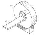
- FIG. 1is a perspective view of a PET or SPECT scanner showing a patient bed with a horizontally oriented source;
- FIG. 2is a pictorial showing the scanner bed, the plane of the detectors, and a horizontally oriented source;
- FIG. 3is a perspective view of PET or SPECT scanner showing a patient bed with an axially oriented source
- FIG. 4is a pictorial showing the scanner bed, the plane of the detectors, and an axially oriented source
- FIG. 5is a section view of a scanner showing the gantry with detectors and an axially oriented line source;
- FIG. 6shows a partial front view of a simulated annular sheet source with a shaped attenuator.
- Apparatus and methods for simulating a sheet source with a line source for determining normalization coefficients for PET and SPECT scanner detectorsare disclosed.
- a line sourcewith a specified orientation with respect to the scanner detectors, is used to simulate a planar or sheet source.
- the detectors in the scannerproduce a sinogram of the simulated sheet source and normalization coefficients are determined from the sinogram.
- FIG. 1illustrates an embodiment of the invention using a line source 110 oriented perpendicular to the axis of the patient tunnel 124 , which simulates a horizontally oriented planar source 210 , shown in FIG. 2 .
- the patient tunnel 124is defined by the tomograph gantry, on which the detectors are attached.
- a line source 110is attached to a patient bed 122 of either a PET or SPECT scanner 120 .
- the line source 110is positioned above the surface of the bed 122 and in front of the bed 122 , resulting in the source 110 being positioned horizontally in the scanner tunnel 124 and without having the bed 122 attenuating the radiation from the source 110 .
- FIG. 2illustrates the relationship of the scanner detectors 222 and 224 to a simulated plane source 210 produced by the horizontal line source 110 .
- the scanner 120has detectors attached to a gantry in a configuration dependant upon the class of tomograph.
- Fixed ring PET scannershave numerous small detectors organized in detector blocks, which are grouped into buckets, and arranged in an arc around the circumference of the gantry.
- Fixed polygonal PET scannershave polygonal arrangements of panel detectors.
- Rotating ring PET scannershave detectors arranged in an arc around the circumference of the gantry, with the detectors rotating about the axis of the gantry, and rotating polygonal ring PET scanners have polygonal arrangements of panel detectors rotating about the axis of the gantry.
- the detectors 222 , 224which can be one or more detector blocks or panels, are illustrated in FIG. 2 as planar panels positioned above and below the simulated plane source 210 .
- the line source 110simulates a plane source 210 when the bed 122 moves in a longitudinal direction 214 . As the bed 122 moves, the line source 110 follows a path 212 , simulating a plane source 210 .
- the source plane 210is substantially parallel to the planes of the detectors 222 , 224 .
- the planes of the detectors 222 , 224can be parallel or at an acute angle to each other, depending upon the configuration of the detectors in the scanner 120 and whether the scanner 120 is a PET or SPECT scanner.
- the line source 110With the line source 110 in a substantially central position vertically in the scanner opening 124 , the line source 110 is located at approximately the same distance from the detectors 222 and 224 , resulting in similar count rates at the detectors 222 and 224 .
- the illustrated embodimentshows a mounting arm 202 securing the source 110 to the bed 122 , with the source 110 positioned in front of the bed 122 such that the bed 122 does not attenuate the detected radiation from the source 110 .
- the line source 110can be mounted on the bed in various ways without departing from the spirit and scope of the present invention.
- the built-in drive system for the bed 122moves the bed 122 along a longitudinal axial path 214 and the attached line source 110 along the planar path 212 at the desired speed.
- the line source 110is illustrated in FIG. 2 with a horizontal orientation, the mounting arm 202 permits the line source 110 to be rotated to the desired orientation.
- the line source 110traverses a horizontal planar path 210 .
- the detectors 222 and 224are held stationary in a fixed position and acquire a sinogram during the time the line source 110 traverses the planar path 210 , resulting in the same sinogram that would be acquired from a sheet source.
- the sinogramis acquired at a fixed orientation of the scanner detectors 222 and 224 . Fixed angle normalization coefficients are directly determined from the sinogram, and normalization coefficients are determined for other angles.
- the patient bed 122 , and consequently, the line source 110move at a uniform speed.
- the line source 110can be at another orientation other than horizontal, provided that the spatial relationship between the line source 110 and the detectors 222 and 224 is maintained, without departing from the spirit and scope of the present invention.
- FIG. 3illustrates an embodiment of the invention using an axially oriented line source 310 , which simulates a vertically oriented planar source 410 , shown in FIG. 4 .
- this arrangementcan be used with either a PET or a SPECT scanner without departing from the spirit and scope of the present invention.
- a line source 310is attached to a patient bed 122 of either a PET or SPECT scanner 120 .
- the line source 310is illustrated positioned above the surface of the bed 122 and extending into the scanner tunnel 124 such that the line source 310 is parallel to the axis formed by the patient tunnel 124 and positioned horizontally in the tunnel 124 .
- Those skilled in the artwill recognize that the relative position of the line source 310 to the bed 122 can be changed without departing from the spirit and scope of the present invention.
- FIG. 4illustrates the relationship of the detectors 222 and 224 to the simulated source plane 410 of the horizontal line source 310 .
- the detectors 222 , 224which can be one or more detector blocks or panels, are illustrated in FIG. 4 as planar panels positioned on either side of the simulated plane source 410 .
- the bed 122moves in a vertical direction 414
- the line source 310follows a path 412 illustrated as a plane source 410 .
- the plane source 410is substantially parallel to the planes of the detectors 222 , 224 .
- the planes of the detectors 222 , 224can be parallel or at an acute angle to each other, depending upon the configuration of the detectors in the scanner 120 and whether the scanner 120 is a PET or SPECT scanner.
- the line source 310is located in a substantially central position horizontally between the side walls of the scanner tunnel 124 , such that the source 310 is at approximately the same distance from the detectors 222 and 224 , resulting in similar count rates at the detectors 222 and 224 .
- the active portion of the line source 310extends past the patient bed 122 such that the bed 122 does not attenuate the radiation from the source 310 and detected by the detectors 222 and 224 .
- the line source 310is as long as or longer than the axial length of the detectors 222 and 224 , and the line source 310 is positioned axially such that the midpoint of its length is substantially at the midpoint of the axial length of the detectors 222 and 224 .
- a line source 310 with a shorter lengthcan be used to determine normalization coefficients of less than all of the detector assembly without departing from the spirit and scope of the present invention.
- the illustrated embodimentdoes not show the attachment of the line source 310 to the patient bed 122 .
- various means for attaching the source 310can be used without departing from the spirit and scope of the present invention.
- other means for moving the line source 310can be used without departing from the spirit and scope of the present invention.
- the line source 310is held in position and moved vertically by an assembly not dependent upon the patient bed 122 for the vertical motion.
- the axial line source 310is moved along a line defining a diameter of the tunnel 124 with the detectors 222 and 224 positioned substantially parallel to the diameter line, such that the spatial relationship between the line source 310 and the detectors 222 and 224 is maintained.
- the line source 310traverses a vertical planar path 410 .
- the scanner detectors 222 and 224are held stationary in a fixed position and acquire a sinogram during the time the line source 310 traverses the planar path 410 .
- the resulting sinogramis identical to the sinogram that would be acquired from a sheet source.
- the sinogramis acquired at a fixed orientation of the scanner detectors 222 and 224 .
- Fixed angle normalization coefficientsare directly determined from the sinogram, and normalization coefficients are determined for other angles.
- the built-in drive system for the bed 122moves the bed 122 along a vertical path 414 and the attached line source 310 along the planar path 412 at the desired speed.
- the patient bed 122 , and consequently, the line source 310moves at a uniform speed.
- the source containeris also thick enough to attenuate the annihilation radiation.
- the attenuation factor due to the thickness of the line source 310 containeris constant for all LORs that comprise a segment of the three-dimensional sinogram.
- FIG. 5illustrates an embodiment of the invention using an axially oriented line source 510 and a fixed ring of detectors 522 , 524 .
- This line source 510is located off-center from the axis of the tunnel 124 and simulates an annular sheet source.
- FIG. 6is a partial front view of a tomography scanner 120 showing the source 610 surrounded by an attenuator 612 .
- this arrangementcan be used with either a PET or a SPECT scanner without departing from the spirit and scope of the present invention.
- a line source 510is positioned axially in the patient tunnel 124 of either a PET or SPECT scanner 120 .
- the line sourceis positioned off-center to the axis of the tunnel 124 and close to the inside surface of the tunnel 124 .
- the configuration of this embodimentis similar to that shown in FIGS. 3 and 4; however, in one embodiment, the line source 510 is held stationary while the detectors 522 and 524 , mounted on a gantry 520 , rotate about a longitudinal axis of the tunnel 124 . By virtue of the rotation, the line source 510 simulates an annular sheet source.
- the detectors 522 and 524While the detectors 522 and 524 rotate and the line source 510 is held stationary, the detectors 522 and 524 acquire a sinogram, resulting in the same sinogram that would be acquired from an annular sheet source.
- This embodimentis suitable for tomographs with detectors that rotate about the axis of the gantry.
- the line source 510is rotated about the axis of the tunnel 124 with the detectors 522 and 524 held stationary.
- This embodimentis suitable for tomographs with fixed detectors and for tomographs with detectors that rotate about the axis of the gantry.
- the line source 510is affixed to the patient bed 122 , with the line source 510 extending past the end of the bed 122 and with the bed not extending into the tunnel 124 such that the bed 122 does not cross the first direct plane of the first detector 522 or 524 , or pair of detectors 522 and 524 , to be normalized.
- the illustrated embodimentdoes not show the attachment of the line source 510 in the tunnel 124 .
- Those skilled in the artwill recognize that various means for attaching the source 510 inside the tunnel 124 can be used without departing from the spirit and scope of the present invention.
- FIG. 6illustrates another embodiment in which a shaped attenuator 612 surrounds a line source 510 . This embodiment is used in an arrangement similar to that illustrated in FIG. 5 .
- the detectors nearest the line source 510receive a higher radiation flux than the detectors further away from the line source 510 .
- a shaped attenuator 612places a larger amount of attenuating material between the line source 510 and the nearer detectors than between the line source 510 and the further detectors.
- the shape, and consequently the attenuation factoris mathematically chosen such that the total path length, that is, the sum of the path lengths of the two quanta emitted in opposite directions, takes on the same value at all angles. To accomplish this, the shaped attenuator 612 maintains a fixed orientation towards the axial center of the tunnel 124 .
- the shaped attenuator 612rotates about the line source 510 such that a point on the surface of the attenuator 612 is fixed relative to the center axis of the tunnel 214 .
- r ⁇ ( ⁇ )C + ⁇ odd ⁇ ⁇ k ⁇ ⁇ a k ⁇ cos ⁇ ⁇ k ⁇ ⁇ ⁇
- ⁇angle in radians, the angle being 0 in the direction of the tomograph's central axis
- a simple shaped attenuator 612as illustrated in FIG. 6, has a form defined by the equation:
- the amount of scattered radiationis increased by surrounding the line source 110 , 310 , 510 in an attenuating medium.
- an attenuating mediumFor example, a hollow tube of lead, steel, or aluminum can be used, in which case, the line source 110 , 310 , 510 is held in the middle of the hollow tube. Scattering the radiation from the line source 110 , 310 , 510 , improves the normalization coefficients.
- the shaped attenuator 612also provides scattered radiation.
- FIG. 5shows five detector pairs in the scanner. Each set of five detectors is arranged in a head, and two heads 522 and 524 are illustrated. Those skilled in the art will recognize that any number of detectors and any number of heads can be used without departing from the spirit and scope of the present invention.
- a line sourcesimulates a sheet, or planar, source, and the simulated source is either flat and planar or annular.
Landscapes
- Health & Medical Sciences (AREA)
- Life Sciences & Earth Sciences (AREA)
- Physics & Mathematics (AREA)
- Medical Informatics (AREA)
- Engineering & Computer Science (AREA)
- Molecular Biology (AREA)
- High Energy & Nuclear Physics (AREA)
- Optics & Photonics (AREA)
- Biomedical Technology (AREA)
- General Health & Medical Sciences (AREA)
- General Physics & Mathematics (AREA)
- Nuclear Medicine, Radiotherapy & Molecular Imaging (AREA)
- Spectroscopy & Molecular Physics (AREA)
- Pathology (AREA)
- Biophysics (AREA)
- Radiology & Medical Imaging (AREA)
- Heart & Thoracic Surgery (AREA)
- Surgery (AREA)
- Animal Behavior & Ethology (AREA)
- Public Health (AREA)
- Veterinary Medicine (AREA)
- Nuclear Medicine (AREA)
Abstract
Description

Claims (23)
Priority Applications (1)
| Application Number | Priority Date | Filing Date | Title |
|---|---|---|---|
| US10/103,276US6774358B2 (en) | 2002-03-21 | 2002-03-21 | Normalization apparatus for PET and SPECT scanners and method for using same |
Applications Claiming Priority (1)
| Application Number | Priority Date | Filing Date | Title |
|---|---|---|---|
| US10/103,276US6774358B2 (en) | 2002-03-21 | 2002-03-21 | Normalization apparatus for PET and SPECT scanners and method for using same |
Publications (2)
| Publication Number | Publication Date |
|---|---|
| US20030178559A1 US20030178559A1 (en) | 2003-09-25 |
| US6774358B2true US6774358B2 (en) | 2004-08-10 |
Family
ID=28040353
Family Applications (1)
| Application Number | Title | Priority Date | Filing Date |
|---|---|---|---|
| US10/103,276Expired - Fee RelatedUS6774358B2 (en) | 2002-03-21 | 2002-03-21 | Normalization apparatus for PET and SPECT scanners and method for using same |
Country Status (1)
| Country | Link |
|---|---|
| US (1) | US6774358B2 (en) |
Cited By (33)
| Publication number | Priority date | Publication date | Assignee | Title |
|---|---|---|---|---|
| US20040206897A1 (en)* | 2003-04-18 | 2004-10-21 | Cti Pet Systems, Inc. | Normalization apparatus for panel detector PET scanners |
| US20050072914A1 (en)* | 2003-09-24 | 2005-04-07 | Chapman James T. | System and method for quality control in nuclear imaging systems |
| US20070131857A1 (en)* | 2002-11-07 | 2007-06-14 | Thompson Christopher J | Instrument and method to facilitate and improve the timing alignment of a pet scanner |
| US20070232881A1 (en)* | 2006-03-31 | 2007-10-04 | Eyal Shai | Method and apparatus for automatically positioning a structure within a field of view |
| US20090134334A1 (en)* | 2005-04-01 | 2009-05-28 | San Diego State University Research Foundation | Edge-on sar scintillator devices and systems for enhanced spect, pet, and compton gamma cameras |
| US20110309252A1 (en)* | 2010-06-17 | 2011-12-22 | Toshiba Medical Systems Corporation | Nuclear medicine imaging apparatus, and nuclear medicine imaging method |
| US8423125B2 (en) | 2004-11-09 | 2013-04-16 | Spectrum Dynamics Llc | Radioimaging |
| US8445851B2 (en) | 2004-11-09 | 2013-05-21 | Spectrum Dynamics Llc | Radioimaging |
| US8489176B1 (en) | 2000-08-21 | 2013-07-16 | Spectrum Dynamics Llc | Radioactive emission detector equipped with a position tracking system and utilization thereof with medical systems and in medical procedures |
| US8492725B2 (en) | 2009-07-29 | 2013-07-23 | Biosensors International Group Ltd. | Method and system of optimized volumetric imaging |
| US8521253B2 (en) | 2007-10-29 | 2013-08-27 | Spectrum Dynamics Llc | Prostate imaging |
| US8565860B2 (en) | 2000-08-21 | 2013-10-22 | Biosensors International Group, Ltd. | Radioactive emission detector equipped with a position tracking system |
| US8571881B2 (en) | 2004-11-09 | 2013-10-29 | Spectrum Dynamics, Llc | Radiopharmaceutical dispensing, administration, and imaging |
| US8606349B2 (en) | 2004-11-09 | 2013-12-10 | Biosensors International Group, Ltd. | Radioimaging using low dose isotope |
| US8610075B2 (en) | 2006-11-13 | 2013-12-17 | Biosensors International Group Ltd. | Radioimaging applications of and novel formulations of teboroxime |
| US8615405B2 (en) | 2004-11-09 | 2013-12-24 | Biosensors International Group, Ltd. | Imaging system customization using data from radiopharmaceutical-associated data carrier |
| US8620046B2 (en) | 2000-08-21 | 2013-12-31 | Biosensors International Group, Ltd. | Radioactive-emission-measurement optimization to specific body structures |
| US8644910B2 (en) | 2005-07-19 | 2014-02-04 | Biosensors International Group, Ltd. | Imaging protocols |
| US8676292B2 (en) | 2004-01-13 | 2014-03-18 | Biosensors International Group, Ltd. | Multi-dimensional image reconstruction |
| US8837793B2 (en) | 2005-07-19 | 2014-09-16 | Biosensors International Group, Ltd. | Reconstruction stabilizer and active vision |
| US8894974B2 (en) | 2006-05-11 | 2014-11-25 | Spectrum Dynamics Llc | Radiopharmaceuticals for diagnosis and therapy |
| US8909325B2 (en) | 2000-08-21 | 2014-12-09 | Biosensors International Group, Ltd. | Radioactive emission detector equipped with a position tracking system and utilization thereof with medical systems and in medical procedures |
| US9040016B2 (en) | 2004-01-13 | 2015-05-26 | Biosensors International Group, Ltd. | Diagnostic kit and methods for radioimaging myocardial perfusion |
| CN104799879A (en)* | 2015-04-16 | 2015-07-29 | 明峰医疗系统股份有限公司 | Portable uniform correcting device for PET equipment and correcting method of portable uniform correcting device |
| US9275451B2 (en) | 2006-12-20 | 2016-03-01 | Biosensors International Group, Ltd. | Method, a system, and an apparatus for using and processing multidimensional data |
| US9316743B2 (en) | 2004-11-09 | 2016-04-19 | Biosensors International Group, Ltd. | System and method for radioactive emission measurement |
| US9470801B2 (en) | 2004-01-13 | 2016-10-18 | Spectrum Dynamics Llc | Gating with anatomically varying durations |
| US9483850B2 (en) | 2013-11-19 | 2016-11-01 | Toshiba Medical Systems Corporation | Cylinder source software-positioning method for PET calibration and image quality assurance |
| US9804275B2 (en) | 2013-11-19 | 2017-10-31 | Toshiba Medical Systems Corporation | Method and system of random-event-based count-rate adaptive normalization for PET detector efficiency |
| US9943274B2 (en) | 2004-11-09 | 2018-04-17 | Spectrum Dynamics Medical Limited | Radioimaging using low dose isotope |
| US10964075B2 (en) | 2004-01-13 | 2021-03-30 | Spectrum Dynamics Llc | Gating with anatomically varying durations |
| US11054534B1 (en) | 2020-04-24 | 2021-07-06 | Ronald Nutt | Time-resolved positron emission tomography encoder system for producing real-time, high resolution, three dimensional positron emission tomographic image without the necessity of performing image reconstruction |
| US11300695B2 (en) | 2020-04-24 | 2022-04-12 | Ronald Nutt | Time-resolved positron emission tomography encoder system for producing event-by-event, real-time, high resolution, three-dimensional positron emission tomographic image without the necessity of performing image reconstruction |
Families Citing this family (11)
| Publication number | Priority date | Publication date | Assignee | Title |
|---|---|---|---|---|
| KR102020531B1 (en) | 2012-08-20 | 2019-09-10 | 삼성전자주식회사 | Method or Apparatus for generating a high-resolution PET(positron emission tomography) image using line gamma-ray source |
| US9128193B2 (en)* | 2012-10-16 | 2015-09-08 | Kabushiki Kaisha Toshiba | Two-axis apparatus with stationary positioning, rotating and/or scanning motion of point or line sources |
| US9645261B2 (en)* | 2013-01-11 | 2017-05-09 | Siemens Medical Solutions Usa, Inc. | Normalization coefficients in PET continuous bed motion acquisition |
| CN107110988B (en) | 2014-10-27 | 2019-04-02 | 皇家飞利浦有限公司 | Pet detector timing alignment |
| CN104825185B (en)* | 2015-05-22 | 2017-10-24 | 武汉数字派特科技有限公司 | A kind of PET image bars source device and PET device |
| CN106137237B (en)* | 2016-08-24 | 2019-11-12 | 东软医疗系统股份有限公司 | Mobile source application and its plane source, the bearing calibration of PET device, device |
| CN106618618A (en)* | 2016-11-21 | 2017-05-10 | 上海联影医疗科技有限公司 | Radioactive source control device and method for medical imaging equipment |
| EP3503810B1 (en) | 2016-09-30 | 2025-02-12 | Shanghai United Imaging Healthcare Co., Ltd. | Method and system for calibrating an imaging system |
| US10282871B2 (en) | 2017-07-10 | 2019-05-07 | Shanghai United Imaging Healthcare Co., Ltd. | Systems and methods for pet image reconstruction |
| CN109077748B (en)* | 2018-08-31 | 2021-08-20 | 北京锐视康科技发展有限公司 | Accurate PET normalization correction method |
| WO2021183454A1 (en)* | 2020-03-10 | 2021-09-16 | University Of Washington | Noncollimated single-photon emission computed tomography |
Citations (4)
| Publication number | Priority date | Publication date | Assignee | Title |
|---|---|---|---|---|
| US5739540A (en)* | 1995-06-23 | 1998-04-14 | Kabushiki Kaisha Toshiba | Nuclear medicine diagnostic apparatus |
| US6429434B1 (en)* | 1998-05-01 | 2002-08-06 | Charles C. Watson | Transmission attenuation correction method for PET and SPECT |
| US6490476B1 (en)* | 1999-10-14 | 2002-12-03 | Cti Pet Systems, Inc. | Combined PET and X-ray CT tomograph and method for using same |
| US20030076988A1 (en)* | 2001-10-18 | 2003-04-24 | Research Foundation Of State University Of New York | Noise treatment of low-dose computed tomography projections and images |
- 2002
- 2002-03-21USUS10/103,276patent/US6774358B2/ennot_activeExpired - Fee Related
Patent Citations (4)
| Publication number | Priority date | Publication date | Assignee | Title |
|---|---|---|---|---|
| US5739540A (en)* | 1995-06-23 | 1998-04-14 | Kabushiki Kaisha Toshiba | Nuclear medicine diagnostic apparatus |
| US6429434B1 (en)* | 1998-05-01 | 2002-08-06 | Charles C. Watson | Transmission attenuation correction method for PET and SPECT |
| US6490476B1 (en)* | 1999-10-14 | 2002-12-03 | Cti Pet Systems, Inc. | Combined PET and X-ray CT tomograph and method for using same |
| US20030076988A1 (en)* | 2001-10-18 | 2003-04-24 | Research Foundation Of State University Of New York | Noise treatment of low-dose computed tomography projections and images |
Non-Patent Citations (1)
| Title |
|---|
| Bailey, Dale L. et al., "An Investigation of Factors Affecting Detector and Geometric Correction in Normalization of 3-D PET Data," IEEE Transactions on Nuclear Science, vol. 43, No. 6, pp. 3300-3307, Dec. 1996. |
Cited By (46)
| Publication number | Priority date | Publication date | Assignee | Title |
|---|---|---|---|---|
| US9370333B2 (en) | 2000-08-21 | 2016-06-21 | Biosensors International Group, Ltd. | Radioactive-emission-measurement optimization to specific body structures |
| US8620046B2 (en) | 2000-08-21 | 2013-12-31 | Biosensors International Group, Ltd. | Radioactive-emission-measurement optimization to specific body structures |
| US8489176B1 (en) | 2000-08-21 | 2013-07-16 | Spectrum Dynamics Llc | Radioactive emission detector equipped with a position tracking system and utilization thereof with medical systems and in medical procedures |
| US8909325B2 (en) | 2000-08-21 | 2014-12-09 | Biosensors International Group, Ltd. | Radioactive emission detector equipped with a position tracking system and utilization thereof with medical systems and in medical procedures |
| US8565860B2 (en) | 2000-08-21 | 2013-10-22 | Biosensors International Group, Ltd. | Radioactive emission detector equipped with a position tracking system |
| US20070131857A1 (en)* | 2002-11-07 | 2007-06-14 | Thompson Christopher J | Instrument and method to facilitate and improve the timing alignment of a pet scanner |
| US7247844B2 (en)* | 2002-11-07 | 2007-07-24 | Scanwell Systems | Instrument and method to facilitate and improve the timing alignment of a pet scanner |
| US20040206897A1 (en)* | 2003-04-18 | 2004-10-21 | Cti Pet Systems, Inc. | Normalization apparatus for panel detector PET scanners |
| US6963065B2 (en)* | 2003-04-18 | 2005-11-08 | Cti Pet Systems, Inc. | Normalization apparatus for panel detector PET scanners |
| US7220961B2 (en)* | 2003-09-24 | 2007-05-22 | Siemens Medical Solutions Usa, Inc. | System and method for quality control in nuclear imaging systems |
| US20050072914A1 (en)* | 2003-09-24 | 2005-04-07 | Chapman James T. | System and method for quality control in nuclear imaging systems |
| US10964075B2 (en) | 2004-01-13 | 2021-03-30 | Spectrum Dynamics Llc | Gating with anatomically varying durations |
| US9470801B2 (en) | 2004-01-13 | 2016-10-18 | Spectrum Dynamics Llc | Gating with anatomically varying durations |
| US9040016B2 (en) | 2004-01-13 | 2015-05-26 | Biosensors International Group, Ltd. | Diagnostic kit and methods for radioimaging myocardial perfusion |
| US8676292B2 (en) | 2004-01-13 | 2014-03-18 | Biosensors International Group, Ltd. | Multi-dimensional image reconstruction |
| US9943278B2 (en) | 2004-06-01 | 2018-04-17 | Spectrum Dynamics Medical Limited | Radioactive-emission-measurement optimization to specific body structures |
| US8423125B2 (en) | 2004-11-09 | 2013-04-16 | Spectrum Dynamics Llc | Radioimaging |
| US8445851B2 (en) | 2004-11-09 | 2013-05-21 | Spectrum Dynamics Llc | Radioimaging |
| US8586932B2 (en) | 2004-11-09 | 2013-11-19 | Spectrum Dynamics Llc | System and method for radioactive emission measurement |
| US8606349B2 (en) | 2004-11-09 | 2013-12-10 | Biosensors International Group, Ltd. | Radioimaging using low dose isotope |
| US9316743B2 (en) | 2004-11-09 | 2016-04-19 | Biosensors International Group, Ltd. | System and method for radioactive emission measurement |
| US8615405B2 (en) | 2004-11-09 | 2013-12-24 | Biosensors International Group, Ltd. | Imaging system customization using data from radiopharmaceutical-associated data carrier |
| US9943274B2 (en) | 2004-11-09 | 2018-04-17 | Spectrum Dynamics Medical Limited | Radioimaging using low dose isotope |
| US8620679B2 (en) | 2004-11-09 | 2013-12-31 | Biosensors International Group, Ltd. | Radiopharmaceutical dispensing, administration, and imaging |
| US10136865B2 (en) | 2004-11-09 | 2018-11-27 | Spectrum Dynamics Medical Limited | Radioimaging using low dose isotope |
| US8571881B2 (en) | 2004-11-09 | 2013-10-29 | Spectrum Dynamics, Llc | Radiopharmaceutical dispensing, administration, and imaging |
| US8748826B2 (en) | 2004-11-17 | 2014-06-10 | Biosensor International Group, Ltd. | Radioimaging methods using teboroxime and thallium |
| US20090134334A1 (en)* | 2005-04-01 | 2009-05-28 | San Diego State University Research Foundation | Edge-on sar scintillator devices and systems for enhanced spect, pet, and compton gamma cameras |
| US7635848B2 (en) | 2005-04-01 | 2009-12-22 | San Diego State University Research Foundation | Edge-on SAR scintillator devices and systems for enhanced SPECT, PET, and compton gamma cameras |
| US8837793B2 (en) | 2005-07-19 | 2014-09-16 | Biosensors International Group, Ltd. | Reconstruction stabilizer and active vision |
| US8644910B2 (en) | 2005-07-19 | 2014-02-04 | Biosensors International Group, Ltd. | Imaging protocols |
| US7693565B2 (en)* | 2006-03-31 | 2010-04-06 | General Electric Company | Method and apparatus for automatically positioning a structure within a field of view |
| US20070232881A1 (en)* | 2006-03-31 | 2007-10-04 | Eyal Shai | Method and apparatus for automatically positioning a structure within a field of view |
| US8894974B2 (en) | 2006-05-11 | 2014-11-25 | Spectrum Dynamics Llc | Radiopharmaceuticals for diagnosis and therapy |
| US8610075B2 (en) | 2006-11-13 | 2013-12-17 | Biosensors International Group Ltd. | Radioimaging applications of and novel formulations of teboroxime |
| US9275451B2 (en) | 2006-12-20 | 2016-03-01 | Biosensors International Group, Ltd. | Method, a system, and an apparatus for using and processing multidimensional data |
| US8521253B2 (en) | 2007-10-29 | 2013-08-27 | Spectrum Dynamics Llc | Prostate imaging |
| US8748827B2 (en) | 2009-07-29 | 2014-06-10 | Biosensors International Group, Ltd. | Method and system of optimized volumetric imaging |
| US8492725B2 (en) | 2009-07-29 | 2013-07-23 | Biosensors International Group Ltd. | Method and system of optimized volumetric imaging |
| US9029786B2 (en)* | 2010-06-17 | 2015-05-12 | Kabushiki Kaisha Toshiba | Nuclear medicine imaging apparatus, and nuclear medicine imaging method |
| US20110309252A1 (en)* | 2010-06-17 | 2011-12-22 | Toshiba Medical Systems Corporation | Nuclear medicine imaging apparatus, and nuclear medicine imaging method |
| US9804275B2 (en) | 2013-11-19 | 2017-10-31 | Toshiba Medical Systems Corporation | Method and system of random-event-based count-rate adaptive normalization for PET detector efficiency |
| US9483850B2 (en) | 2013-11-19 | 2016-11-01 | Toshiba Medical Systems Corporation | Cylinder source software-positioning method for PET calibration and image quality assurance |
| CN104799879A (en)* | 2015-04-16 | 2015-07-29 | 明峰医疗系统股份有限公司 | Portable uniform correcting device for PET equipment and correcting method of portable uniform correcting device |
| US11054534B1 (en) | 2020-04-24 | 2021-07-06 | Ronald Nutt | Time-resolved positron emission tomography encoder system for producing real-time, high resolution, three dimensional positron emission tomographic image without the necessity of performing image reconstruction |
| US11300695B2 (en) | 2020-04-24 | 2022-04-12 | Ronald Nutt | Time-resolved positron emission tomography encoder system for producing event-by-event, real-time, high resolution, three-dimensional positron emission tomographic image without the necessity of performing image reconstruction |
Also Published As
| Publication number | Publication date |
|---|---|
| US20030178559A1 (en) | 2003-09-25 |
Similar Documents
| Publication | Publication Date | Title |
|---|---|---|
| US6774358B2 (en) | Normalization apparatus for PET and SPECT scanners and method for using same | |
| Jaszczak et al. | Single photon emission computed tomography using multi-slice fan beam collimators | |
| van der Have et al. | System calibration and statistical image reconstruction for ultra-high resolution stationary pinhole SPECT | |
| Moore et al. | Collimator design for single photon emission tomography | |
| US7465927B2 (en) | Attenuation correction for nuclear medical imaging scanners with simultaneous transmission and emission acquisition | |
| Jaszczak et al. | Single photon emission computed tomography (SPECT) principles and instrumentation | |
| Metzler et al. | Molecular imaging of small animals with a triple-head SPECT system using pinhole collimation | |
| JP2006516742A (en) | Single photon emission computed tomography system | |
| US5296708A (en) | Method and apparatus for transmission measurements to form a 3-D image in tomography applications | |
| JP2002541486A (en) | Single photon emission computed tomography system | |
| JP2004532401A5 (en) | ||
| Lim et al. | Triangular SPECT system for 3-D total organ volume imaging: design concept and preliminary imaging results | |
| Lee et al. | Multipinhole collimator with 20 apertures for a brain SPECT application | |
| US7378661B2 (en) | Asymmetrical positron emission tomograph detectors | |
| CN1537515A (en) | Combined device for tomography and radiographic projection systems | |
| Kemp et al. | Transmission computed tomography imaging of the head with a SPECT system and a collimated line source | |
| Park et al. | Performance of a high‐sensitivity dedicated cardiac SPECT scanner for striatal uptake quantification in the brain based on analysis of projection data | |
| JP3778094B2 (en) | Radiation inspection equipment | |
| Phelps et al. | Design considerations in positron computed tomography (PCT) | |
| JPH095443A (en) | Nuclear medicine diagnostic equipment | |
| McElroy et al. | Evaluation of A-SPECT: a desktop pinhole SPECT system for small animal imaging | |
| JP3881403B2 (en) | Nuclear medicine diagnostic equipment | |
| Badawi | Aspects of Optimisation and Quantification in Three Dimensional Positron Emission Tomography | |
| Bailey et al. | Nuclear medicine: from photons to physiology | |
| US11000240B2 (en) | System and method of positron emission tomography with two axes of rotation |
Legal Events
| Date | Code | Title | Description |
|---|---|---|---|
| AS | Assignment | Owner name:CTI PET SYSTEMS, INC., TENNESSEE Free format text:ASSIGNMENT OF ASSIGNORS INTEREST;ASSIGNORS:HAMILL, JAMES J.;CASEY, MICHAEL E.;GREMILLION, TIMOTHY G.;REEL/FRAME:012719/0769;SIGNING DATES FROM 20020305 TO 20020312 | |
| AS | Assignment | Owner name:CTI PET SYSTEMS, INC., TENNESSEE Free format text:ASSIGNMENT OF ASSIGNORS INTEREST;ASSIGNORS:LUK, WING K.;MILLER, STEPHEN;REEL/FRAME:014219/0607;SIGNING DATES FROM 20020306 TO 20020308 | |
| AS | Assignment | Owner name:SIEMENS MEDICAL SOLUTIONS USA, INC.,PENNSYLVANIA Free format text:MERGER;ASSIGNOR:CTI PET SYSTEMS, INC.;REEL/FRAME:018535/0183 Effective date:20060930 Owner name:SIEMENS MEDICAL SOLUTIONS USA, INC., PENNSYLVANIA Free format text:MERGER;ASSIGNOR:CTI PET SYSTEMS, INC.;REEL/FRAME:018535/0183 Effective date:20060930 | |
| FPAY | Fee payment | Year of fee payment:4 | |
| FPAY | Fee payment | Year of fee payment:8 | |
| REMI | Maintenance fee reminder mailed | ||
| LAPS | Lapse for failure to pay maintenance fees | ||
| STCH | Information on status: patent discontinuation | Free format text:PATENT EXPIRED DUE TO NONPAYMENT OF MAINTENANCE FEES UNDER 37 CFR 1.362 | |
| FP | Lapsed due to failure to pay maintenance fee | Effective date:20160810 |