US6773399B2 - Block-switching in ultrasound imaging - Google Patents
Block-switching in ultrasound imagingDownload PDFInfo
- Publication number
- US6773399B2 US6773399B2US10/039,922US3992201AUS6773399B2US 6773399 B2US6773399 B2US 6773399B2US 3992201 AUS3992201 AUS 3992201AUS 6773399 B2US6773399 B2US 6773399B2
- Authority
- US
- United States
- Prior art keywords
- subset
- ultrasound
- transducer elements
- data
- image
- Prior art date
- Legal status (The legal status is an assumption and is not a legal conclusion. Google has not performed a legal analysis and makes no representation as to the accuracy of the status listed.)
- Expired - Lifetime, expires
Links
- 238000012285ultrasound imagingMethods0.000titleclaimsdescription5
- 238000002604ultrasonographyMethods0.000claimsabstractdescription138
- 238000000034methodMethods0.000claimsabstractdescription49
- 239000000463materialSubstances0.000claimsdescription20
- 238000011835investigationMethods0.000claimsdescription13
- 238000002592echocardiographyMethods0.000claimsdescription7
- 230000008878couplingEffects0.000claimsdescription2
- 238000010168coupling processMethods0.000claimsdescription2
- 238000005859coupling reactionMethods0.000claimsdescription2
- 230000007340echolocationEffects0.000claims3
- 230000008569processEffects0.000abstractdescription20
- 238000010276constructionMethods0.000abstract1
- 238000005516engineering processMethods0.000description9
- 230000005284excitationEffects0.000description7
- 238000006073displacement reactionMethods0.000description5
- 239000000711locust bean gumSubstances0.000description5
- 238000004458analytical methodMethods0.000description4
- 238000003491arrayMethods0.000description3
- 230000005540biological transmissionEffects0.000description3
- 239000004020conductorSubstances0.000description3
- 230000002596correlated effectEffects0.000description3
- 238000007792additionMethods0.000description2
- 239000002131composite materialSubstances0.000description2
- 230000000694effectsEffects0.000description2
- 230000009467reductionEffects0.000description2
- 239000004173sunset yellow FCFSubstances0.000description2
- 230000002238attenuated effectEffects0.000description1
- 230000015572biosynthetic processEffects0.000description1
- 238000004364calculation methodMethods0.000description1
- 230000008859changeEffects0.000description1
- 238000006243chemical reactionMethods0.000description1
- 239000002872contrast mediaSubstances0.000description1
- 230000000875corresponding effectEffects0.000description1
- 239000013078crystalSubstances0.000description1
- 238000001514detection methodMethods0.000description1
- 239000003814drugSubstances0.000description1
- 230000007717exclusionEffects0.000description1
- 238000003384imaging methodMethods0.000description1
- 238000012545processingMethods0.000description1
- 230000004044responseEffects0.000description1
- 239000000523sampleSubstances0.000description1
- 238000012800visualizationMethods0.000description1
Images


Classifications
- G—PHYSICS
- G01—MEASURING; TESTING
- G01S—RADIO DIRECTION-FINDING; RADIO NAVIGATION; DETERMINING DISTANCE OR VELOCITY BY USE OF RADIO WAVES; LOCATING OR PRESENCE-DETECTING BY USE OF THE REFLECTION OR RERADIATION OF RADIO WAVES; ANALOGOUS ARRANGEMENTS USING OTHER WAVES
- G01S15/00—Systems using the reflection or reradiation of acoustic waves, e.g. sonar systems
- G01S15/88—Sonar systems specially adapted for specific applications
- G01S15/89—Sonar systems specially adapted for specific applications for mapping or imaging
- G01S15/8906—Short-range imaging systems; Acoustic microscope systems using pulse-echo techniques
- G01S15/8909—Short-range imaging systems; Acoustic microscope systems using pulse-echo techniques using a static transducer configuration
- G01S15/8915—Short-range imaging systems; Acoustic microscope systems using pulse-echo techniques using a static transducer configuration using a transducer array
- G01S15/8927—Short-range imaging systems; Acoustic microscope systems using pulse-echo techniques using a static transducer configuration using a transducer array using simultaneously or sequentially two or more subarrays or subapertures
- G—PHYSICS
- G01—MEASURING; TESTING
- G01S—RADIO DIRECTION-FINDING; RADIO NAVIGATION; DETERMINING DISTANCE OR VELOCITY BY USE OF RADIO WAVES; LOCATING OR PRESENCE-DETECTING BY USE OF THE REFLECTION OR RERADIATION OF RADIO WAVES; ANALOGOUS ARRANGEMENTS USING OTHER WAVES
- G01S15/00—Systems using the reflection or reradiation of acoustic waves, e.g. sonar systems
- G01S15/88—Sonar systems specially adapted for specific applications
- G01S15/89—Sonar systems specially adapted for specific applications for mapping or imaging
- G01S15/8906—Short-range imaging systems; Acoustic microscope systems using pulse-echo techniques
- G01S15/8993—Three dimensional imaging systems
- G—PHYSICS
- G01—MEASURING; TESTING
- G01S—RADIO DIRECTION-FINDING; RADIO NAVIGATION; DETERMINING DISTANCE OR VELOCITY BY USE OF RADIO WAVES; LOCATING OR PRESENCE-DETECTING BY USE OF THE REFLECTION OR RERADIATION OF RADIO WAVES; ANALOGOUS ARRANGEMENTS USING OTHER WAVES
- G01S15/00—Systems using the reflection or reradiation of acoustic waves, e.g. sonar systems
- G01S15/88—Sonar systems specially adapted for specific applications
- G01S15/89—Sonar systems specially adapted for specific applications for mapping or imaging
- G01S15/8906—Short-range imaging systems; Acoustic microscope systems using pulse-echo techniques
- G01S15/8995—Combining images from different aspect angles, e.g. spatial compounding
- G—PHYSICS
- G01—MEASURING; TESTING
- G01S—RADIO DIRECTION-FINDING; RADIO NAVIGATION; DETERMINING DISTANCE OR VELOCITY BY USE OF RADIO WAVES; LOCATING OR PRESENCE-DETECTING BY USE OF THE REFLECTION OR RERADIATION OF RADIO WAVES; ANALOGOUS ARRANGEMENTS USING OTHER WAVES
- G01S7/00—Details of systems according to groups G01S13/00, G01S15/00, G01S17/00
- G01S7/52—Details of systems according to groups G01S13/00, G01S15/00, G01S17/00 of systems according to group G01S15/00
- G01S7/52017—Details of systems according to groups G01S13/00, G01S15/00, G01S17/00 of systems according to group G01S15/00 particularly adapted to short-range imaging
- G01S7/52019—Details of transmitters
- G01S7/5202—Details of transmitters for pulse systems
- G—PHYSICS
- G03—PHOTOGRAPHY; CINEMATOGRAPHY; ANALOGOUS TECHNIQUES USING WAVES OTHER THAN OPTICAL WAVES; ELECTROGRAPHY; HOLOGRAPHY
- G03B—APPARATUS OR ARRANGEMENTS FOR TAKING PHOTOGRAPHS OR FOR PROJECTING OR VIEWING THEM; APPARATUS OR ARRANGEMENTS EMPLOYING ANALOGOUS TECHNIQUES USING WAVES OTHER THAN OPTICAL WAVES; ACCESSORIES THEREFOR
- G03B42/00—Obtaining records using waves other than optical waves; Visualisation of such records by using optical means
- G03B42/06—Obtaining records using waves other than optical waves; Visualisation of such records by using optical means using ultrasonic, sonic or infrasonic waves
Definitions
- the inventionis in the field of medical devices and more particularly in the field of ultrasound imaging.
- Ultrasound imagingis a common method of analysis used for examining a wide range of materials. The method is especially common in medicine because of its relatively non-invasive nature, low cost, and fast response times.
- ultrasound imagingis accomplished by generating and directing ultrasonic sound waves into a material under investigation in a transmit phase and observing reflections generated at the boundaries of dissimilar materials in a receive phase. For example, reflections are generated at boundaries between a patient's tissues. The reflections are converted to electrical signals by receiving devices (transducers) and processed, using beam-forming techniques known in the art, to determine the locations of echo sources. The resulting data is displayed using a display device such as a monitor.
- the ultrasonic signal transmitted into the material under investigationis generated by applying continuous or pulsed electronic signals to a transducer.
- the transmitted ultrasoundis commonly in the range of 1 MHz to 15 MHz.
- the ultrasoundpropagates through the material under investigation and reflects off of structures such as boundaries between adjacent tissue layers.
- the ultrasonic energymay be scattered, resonated, attenuated, reflected, or transmitted.
- a portion of the reflected signalsare returned to the transducers and detected as echoes.
- the detecting transducersconvert the echo signals to electronic signals and furnish them to a beamformer.
- the beamformercalculates locations of echo sources along a line (beam) and typically includes simple filters.
- an image scan converteruses the calculated positional information, resulting form several beams, to generate two dimensional data that can be presented as an image.
- the image formation rate(the frame rate) is limited by at least the pulse round trip time.
- the pulse round trip timeis the time between the transmission of ultrasonic sound into the media of interest and the detection of the last reflected signals.
- harmonic frequency componentsare generated. These additional harmonic frequency components continue to propagate and, in turn, reflect off of or interact with other structures in the material under investigation. Both fundamental and harmonic signals are detected.
- the analysis of harmonic signalsis generally associated with the visualization of boundaries or image contrast agents designed to re-radiate ultrasound at specific harmonic frequencies.
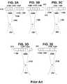
- FIG. 1shows a prior art ultrasound system, generally designated 100 .
- the ultrasound system 100includes an element array 105 of transducer elements 110 A- 110 H, a backing material 120 , and a matching layer 130 .
- Backing material 120is designed to support element array 105 and dampen any ultrasound energy that propagates toward backing material 120 .
- Matching layer 130transfers ultrasound energy from transducer elements 110 A- 110 H into a material of interest (not shown).
- Transducer elements 110 A- 110 Hare each individually electronically coupled by conductors 115 and 117 , through a transmit/receive switch 140 to a beam transmitter 150 .
- transducer elements 110 A- 110 Hare typically piezoelectric crystals.
- Transmit/receive switch 140typically includes a multiplexer 145 , allowing the number of conductors 117 to be smaller than the number of conductors 115 .
- beam transmitter 150generates electronic pulses that are coupled through transmit/receive switch 140 , and applied to transducer elements 110 A- 110 H and converted to ultrasound pulses 160 .
- ultrasound pulses 160form an ultrasound beam 170 that probes a material of interest. Ultrasound beam 170 is focused to improve the spatial resolution of the ultrasound analysis.
- FIGS. 2A and 2Bshow a prior art focusing method in which element array 105 is a phased array used to focus ultrasound beam 170 by varying the timing of electronic pulses 210 applied to transducer elements 110 A- 110 H.
- Electronic pulses 210are generated at beam transmitter 150 .
- FIGS. 2A and 2Bshow two series of electronic pulses 210 each with a different set of delay times resulting in different focal points 230 .
- phased excitation of array 105is used to direct (steer) ultrasound beam 170 in specific directions.
- Ultrasound system 100sends a series of ultrasound beam 170 through different paths to form an image with a cross-sectional area greater than the width of each individual ultrasound beam 170 .
- Multiple beamsare directed from ultrasound system 100 in a scanning or steering process.
- An ultrasound scanincludes transmission of more than one distinct ultrasound beam 170 in order to image an area larger than each individual ultrasound beam 170 .
- a receive phaseoccurs during which echoes are detected. Since each ultrasound beam 170 , included in the ultrasound scan, requires at least one transmit/receive cycle, the scanning processes can require many times the pulse round trip time.
- an ultrasound beam 170is transmitted in several transmit/receive cycles before another ultrasound beam 170 is generated. If ultrasound transducers 110 A- 110 H move relative to the material under investigation during the scanning process undesirable artifacts can be generated.
- FIG. 3A through 3Eshow a prior art scanning process in a transducer array 310 of eight transducer elements, designated 110 A through 110 H. Electrical pulses are applied to subsets 320 A- 320 E of the eight transducer elements 100 A- 110 H.
- FIG. 3Ashows ultrasound beam 170 A formed by subset 320 A including transducer elements 110 A- 110 D.
- the next step in the scanning processincludes ultrasound beam 170 B formed by subset 320 B including transducer elements 110 B- 110 E as shown in FIG. 3 B.
- Subset 320 Bincludes most (seventy-five percent) of the transducer elements 110 A- 110 H found in subset 320 A.
- Subset 320 A and subset 320 Bdiffer by two transducer elements 110 A- 110 H, the difference includes the inclusion of one and the removal of another.
- the center of ultrasound beam 170 Bpasses through focal point 230 and is displaced from the center of ultrasound beam 170 A by a distance equal to one transducer element 110 .
- each subset 320 C through 320 E, used to produce each ultrasound beam 170 C through 170 Eis displaced by one transducer element 110 relative to the subset 320 B through 320 D used to generate the previous ultrasound beam 170 B through 170 D. Echoes detected in the receive phase that occurs between each ultrasound beam 170 transmission are used to generate beam echo data.
- Analyses of the beam echo dataare combined and scan converted to form an image and the scan process is repeated to produce multiple images.
- the subsets 320 A- 320 E of transducer elements 110 A- 110 H used to produce ultrasound beams 170 A- 170 Eare selected using an array of switches and multiplexer 145 . These switches are typically located in transmit/receive switch 140 .
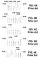
- FIG. 4A through 4Eshow prior art examples of the states of switches 410 A- 410 H used to generate five consecutive ultrasound beams 170 A- 170 E.
- the state of each switch 410determines which of transducer elements 110 A- 110 H are coupled to beam transmitter 150 and therefore excited. For example, in FIG. 4A the first four switches 410 A- 410 D are closed and the second four switches 410 E- 410 H are open. This condition results in a beam 170 A generated by excitation of the first four transducer elements 110 A- 110 C as in FIG. 3 A. In FIG. 4B the first switch 410 A is open, the next four switches 410 B- 410 D are closed, and the last three switches 410 E- 410 H are open. As illustrated in FIG.
- this change in switch 410 settingspositions the center of the resulting ultrasound beam 170 B a distance, approximately equal to the width of one transducer element 110 , from the center of the previous ultrasound beam 170 A.
- FIG. 4Cthe first two switches 410 A and 410 B are open, the next four switches 410 C- 410 F are closed, and the last two switches 410 G and 410 H are open.
- This switch 410 settingresults in ultrasound beam 170 C displaced by one transducer element 110 from ultrasound beam 170 B, as illustrated in FIG. 3 C.
- FIGS. 4D and 4Eillustrate switch 410 settings used to produce ultrasound beams 170 D and 170 E shown in FIGS. 3D and 3E respectively.
- Some prior art systemsuse electronically controlled switches 410 and multiplexer 145 to select the subset 320 of transducer elements 110 A- 110 H used to produce ultrasound beam 170 . Regardless of the control means, the subsets 320 of transducer elements 110 A- 110 H used to produce ultrasound beam 170 , during the scanning process, differ by the inclusion and exclusion of one transducer element 110 .
- the time required to scan over a large array of transducer element 110is a significant factor in the time required to form an ultrasound image.
- Arraysoptionally include a greater number of transducer element 100 , for example, sixty-four, one hundred and twenty-eight, or more.
- transmit/receive switch 140When used to control arrays with greater numbers of transducer element 100 , transmit/receive switch 140 includes multiplexer 145 that couples more than one beam transmitter 150 output to a greater number of transducer elements 110 . Except at the edges of element transducer array 310 , every output of beam transmitter 150 is coupled to every transducer element 110 . This coupling is required since a transducer element 110 in the center of transducer array 310 is alternatively excited by all of the outputs of beam transmitter 150 . For example, as illustrated in FIGS. 3A-3E, transducer element 110 D is included in different positions within the four subsets 320 A- 320 D. Each position is typically associated with a specific output of beam transmitter 150 . In the prior art, a typical transducer element 110 is used to generate four, eight, or more distinct ultrasound beam 170 .
- FIG. 1shows a prior art ultrasound system
- FIGS. 2A and 2Bshow a prior art focusing method
- FIGS. 3A through 3Eshow a prior art scan process in a phased array of eight transducer elements
- FIGS. 4A through 4Eshow a prior art example of the states of switches used to generate five consecutive ultrasound beams
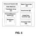
- FIG. 5shows an ultrasound system in accordance with an embodiment of the invention
- FIGS. 6A through 6Cshow three consecutive states of switches configured in accordance with an embodiment of the invention
- FIGS. 7A through 7Cshow ultrasound beams generated by the switch configurations shown in FIG. 6;
- FIGS. 8A and 8Bshow two configurations wherein switches are set to excite subsets of transducer elements in accordance with an embodiment of the invention
- FIGS. 9A and 9Bshow ultrasound beams generated by the switch configurations of FIGS. 8A and 8B respectively;
- FIG. 10shows a flow chart for executing a scan according with one embodiment of the invention.
- FIG. 11shows a flow chart for forming an image according with one embodiment of the invention.
- An ultrasound systemincluding an array of ultrasound transducer elements configured to produce ultrasound beams.
- the beamsare generated using subsets of the ultrasound transducer elements wherein the subsets differ by a shift of more than one transducer element.
- This “block-switching”in enabled by a block-switching multiplexer and reduces the number of transmit/receive cycles required to generate an image of a given area without reducing the resolution of the image.
- the inventionuses broad-beam technologies to determine locations of echo sources and form an image. Detected echoes are processed using area-forming techniques to generate data that is optionally used to produce an image. In broad-beam technologies the processes that determine lateral spatial resolution (focusing) occur during data processing of the detected signals. Thus, this method is different from prior art that accomplished focusing merely through timing of transducer element 110 excitation. Broad-,beam technologies also allow an image to be formed over an area using a single transmit/receive cycle. Broad-beam technologies eliminate the need to gradually scan or steer a focused beam over an area to generate a two dimensional image. The resolution of images generated using broad-beam technologies is independent of the distance or number of transducer elements that an ultrasound excitation pulse is displaced between transmit/receive cycles.
- FIG. 5shows an ultrasound system 500 in accordance with an embodiment of the invention.
- Ultrasound system 500includes a scan head 510 having transducer array 310 of transducer elements 110 A- 110 H used to apply ultrasound signals to a material under investigation.
- transducer array 310is a linear array, curvilinear array, phased array, EV array, EC array, or the like.
- Data generated by scan head 510passes through transmit/receive switch 515 and is processed by area-former 520 to generate positional information. Since area-forming is used, two-dimensional positional data representing an area can be generated even if that area is covered by only one ultrasound beam.
- Ultrasound system 500also includes computer code 530 , configured to manage ultrasound system 500 , as well as to control transmit/receive switch 515 , beam transmitter 150 , area-former 520 , and image scan converter 530 .
- Transmit/receive switch 515optionally includes a multiplexer 517 .
- multiplexer 517is a block-switching multiplexer controlled by computer code.
- subsets 320 A, 320 C, and 320 E of transducer array 310are sequentially excited such that subset 320 C is the only subset 320 of transducer elements 110 A- 110 H operative between a time subset 320 A is operative and a time subset 320 E is operative.
- Each of the sequentially excited subsets 320 A, 320 C, and 320 Eis displaced by a shift of more than one transducer element 110 .
- each subset 320 A, 320 C, and 320 Ediffers by the addition of more than one transducer element 110 and the removal of more than one of the transducer element 110 .
- block-switchingThe method of displacing sequentially excited subsets 320 A, 320 C, and 320 E by a shift of more than one transducer element 110 is called “block-switching” and a transmit/receive switch 515 configured to execute this method is called a “block-switching switch.”
- FIGS. 6A through 6Cshow an embodiment exercising three consecutive states of switches 410 A- 410 H configured such that the subsets 320 A, 320 C, and 320 E, consecutively excited during a scan, are displaced by at least two of transducer elements 110 A- 110 H. Each subset 320 , therefore, differs in position by at least fifty percent of the number of transducer elements in subset 320 C.
- the state (open or closed) of each switch 410determines which of transducer elements 110 A- 110 H are coupled to beam transmitter 150 and therefore excited. For example, in FIG. 6A the first four switches 410 A- 410 D are closed and the last four switches 410 E- 410 H are open.
- switches 410 A- 410 Dresults in excitation of subset 320 A of transducer array 310 including transducer elements 110 A- 110 D.
- the next switch configurationis shown in FIG. 6 B.
- the first two switches 410 A- 410 B and last two switches 410 G- 410 Hare open, and the middle four switches 410 C- 410 F are closed.
- Two ( 110 A and 110 B) of the transducer elements 110 A- 110 D excited in the previous configurationare no longer excited.
- FIG. 6Cin the next configuration the group of closed switches is again shifted by two transducer elements 110 A- 110 H. This process is repeated for each scan used to generated an image.
- each subset 320is displaced from the center of the other subsets 320 A, 320 C, or 320 E by a distance greater than or equal to the width of two transducer elements 110 A- 110 H.
- the overlaps between subsets 320 A, 320 C, and 320 Eare optionally less than eighty-seven, thirty -four, or thirteen percent of width of subset 320 C and can alternatively be less than the width of three transducer elements 110 . Since broad-beam technologies are used, the resolution of the formed image is substantially independent of the number of ultrasound elements common to each subset.
- FIG. 7A through 7Cshow ultrasound beams 710 A- 710 C generated by the switch 410 configurations shown in FIG. 6 .
- ultrasound beam 710is generated by subset 320 A including the first four transducer elements 110 A- 110 D and thus corresponding to the switch 410 configuration of FIG. 6 A.
- ultrasound beam 710 Bis generated by subset 320 C including the middle four transducer elements 110 C- 110 F.
- ultrasound beam 710 Cis generated by a subset 320 E including the final four transducer elements 110 E- 110 H.
- the generated beams 710 A- 710 Coverlap by a small fraction of their width. (Overlap is measured at the transducer surface.)
- the centers of the generated beams 710 A- 710 Care separated by the width of two or more transducer element 110 .
- the subsets 320 A, 320 C, and 320 E of transducer array 310 used to generate each ultrasound beam 710 A- 710 Care optionally differentiated by a displacement equal to or greater than a number of transducer elements 110 A- 110 H in each subset 320 A, 320 C, or 320 E. In various embodiments this displacement is more than, four or more than eight transducer elements. However, if the shift (displacement) is greater than the number of elements in each subset 320 A, 320 C, or 320 E, image resolution, uniformity, and continuity may be degraded.
- FIGS. 8A and 8Bshow two configurations wherein switches 410 A- 410 D are set such that the excited subsets 320 A and 320 E are differentiated by a shift equal to a number of transducer elements 110 A- 110 H in each subset 320 .
- switches 410 A- 410 Dare set such that the excited subsets 320 A and 320 E are differentiated by a shift equal to a number of transducer elements 110 A- 110 H in each subset 320 .
- FIG. 8Athe first four switches 410 A- 410 D are closed and the last four switches 410 E- 410 H are open.
- This configurationresults in the excitation of the first four transducer elements 110 A- 110 D and the generation of ultrasound beam 710 C, as shown in FIG. 7 C.
- FIG. 8Ashows two configurations wherein switches 410 A- 410 D are set such that the excited subsets 320 A and 320 E are differentiated by a shift equal to a number of transducer elements 110 A-
- FIG. 8Bshows the switch 410 settings used to generate the next ultrasound beam 710 C wherein the first four switches 410 A- 410 D are open and the last four switches 410 E- 410 H are closed.
- Subsets 320 A and 320 Bhave no transducer elements 110 A- 110 H in common, and are therefore disjoint sets.
- FIGS. 9A and 9Bshow ultrasound beams 710 A and 710 C generated by the switch configurations of FIGS. 8A and 8B respectively.
- FIG. 9Ashows an ultrasound beam 710 A generated by exciting subset 320 A including the first four transducer elements 110 A- 110 D and
- FIG. 9Bshows an ultrasound beam 710 C generated by exciting subset 320 E including last four transducer elements 110 E- 110 H.
- Differentiating subsets 320 A, 320 C, and 320 E, used to form ultrasound beams 710 A- 710 C, by a displacement of more than one transducer element 110reduces the number of transmit/receive cycles required to image an area in comparison with prior art methods.
- the prior art method illustrated in FIG. 3requires five ultrasound beams 170 A- 170 E to image a volume smaller than the volume imaged by the two ultrasound beams 710 A- 710 C shown in FIG. 9 .
- Reducing the number of ultrasound beams and associated transmit/receive cyclesreduces the power and time required to image an area, since each ultrasound beam 710 requires at least one transmit/receive cycle and each transmit/receive cycle takes at least the pulse round trip time.
- each ultrasound beamis optionally used to image an area more that one ultrasound transducer wide
- data used to image an area greater than one transducer element wideis generated in less than two pulse round trip times. (Width is measured at the surface of the transducer array.)
- Ultrasound system 500should not be construed as being limited by or to the number of transducer elements 110 A- 110 H shown in any of FIGS. 6-10. Both the total number of transducer elements 110 and the number of transducer elements 110 A- 110 H within each subset 320 used to form ultrasound beams 710 A- 710 C are optionally larger or smaller then those shown.
- the systems and methods described hereinare also used with a variety of transducer array 310 geometries including linear and curved systems.
- Block-switchingreduces the complexity of transmit/receive switch 515 and multiplexer 517 in comparison to the prior art. This reduced complexity occurs in embodiments wherein each output of beam transmitter 150 is not coupled to some transducer element 110 of transducer array 310 . In contrast with the prior art, each transducer element 110 is optionally used to generated no more than two ultrasound beams 710 A- 710 C. In various embodiments, each output from transmit/receive switch 515 is coupled to less than three or less than eight inputs to transmit/receive switch 515 . In another embodiment each output from transmit/receive switch 515 is coupled to less than eighty-seven percent of inputs to transmit/receive switch 515 .
- each of the excited subsets 320 A- 320 Eoverlap by a small number of transducer elements 110 A- 110 H. This overlap is typically less than fifty percent and sometimes less than thirty-three percent of the size of subsets 320 A- 320 E, and is optionally as small as one or two of transducer elements 110 A- 110 H.
- a small overlapenables comparison between data generated using different ultrasound beams 710 A- 710 C. In one embodiment this comparison includes a cross-correlation calculation used to detect correlated changes in echo positions resulting from relative movement between scan head 510 and the material under investigation. These changes in echo positions potentially cause artifacts in images generated using different ultrasound beams 710 A- 710 C. Cross-correlation results are used by computer code 540 to reduce the effect of the relative movement on the quality of the resulting image.
- FIG. 10shows steps included in a method of executing a scan according to one embodiment of the invention.
- 1010 subset 320 A of transducer elements 110 A- 110 His selected for excitation using switches 410 A- 410 D.
- an ultrasound beam 710 generation step 1020a transmit/receive cycle is executed. This cycle includes exciting selected subset 320 A, transmitting ultrasound beam 710 into the material under investigation, and detecting echoes generated thereby.
- computer code 540determines if the current scan is completed. If not, the process continues to a select new subset step 1040 which selects a new subset 320 .
- the new subset 320differs in position from the previously selected subset 320 by a displacement of more than one transducer element 110 .
- the new subset 320 selected in step 1040optionally includes zero, one, or two transducer elements 110 A- 110 H in common with subset 320 previously selected in step 1010 or step 1040 .
- step 1020is repeated again. If in step 1030 computer code 540 determines that the current scan is complete, the process continues to a query another scan step 1050 . Step 1050 uses computer code 540 to determine if another scan is to be executed. If so, the process returns to step 1010 , and if not the process is completed.
- FIG. 11shows steps in a method for forming an image according to one embodiment of the invention.
- a transmit/receive cycleis executed. This transmit/receive cycle generates echo data that is optionally filtered and otherwise processed, the echo data is subsequently provided to area-former 520 , in a provide echo data to area former 520 step 1115 .
- Area-former 520uses the echo data to generate positional data in generate positional data step 1120 .
- the positional dataincludes information about the locations of echo sources within the material under investigation. Since broad-beam technologies are used, a single ultrasound beam 710 transmitted using a single subset 320 , generates positional data over a two dimensional area.
- a provide positional data to image scan converter 530 step 1125the positional data is provided to image scan converter 530 which converts the data to an x-y coordinate system suitable for image viewing.
- the x-y positional datais stored in a store positional data step 1130 .
- computer code 540is used to determine if the current scan is completed. If not, th e process returns to step 1110 to execute another transmit/receive cycle, possibly using a new ultrasound beam 710 . If the scan is completed, then the process proceeds to an execute cross-correlation step 1130 , wherein cross-correlation is performed on the positional data stored in step 1130 .
- the positional data stored in step 1130includes data generated using a plurality of ultrasound beams 720 A- 720 C that are in turn generated using a plurality of subsets 320 A, 320 C, and 320 E.
- the cross-correlationis specifically applied to data covering overlapping positions and resulting from different transmit/receive cycles. For example, in one aspect of the cross-correlation, data generated using subsets 320 A and 320 C are correlated.
- the cross-correlationdetects correlated shifts in the positions of features within the data. For example, if scan head 510 moves one millimeter in relation to the material under investigation the cross-correlation will detect and determine the magnitude of this movement.
- Cross-correlationis one means of comparing data and optionally includes a fraction of the data generated using each subset 320 .
- the cross-correlationcan include less than fifty percent or less than thirty-four percent of the data generated using a specific subset 320 . In alternative embodiments other well known methods of comparison are employed.
- a determine spatial adjustments step 1145the positional adjustment required to reduce the effects of any movement are determined from the cross-correlation results.
- the positional adjustment informationis used to adjust the positional data with respect to the spatial alignment of regions in the image that is generated using subsets 320 A, 320 C, and 320 E.
- a combine positional data step 1160the positional data are combined to form a composite set of positional data, optionally without artifacts resulting from relative movement of the material under investigation and scan head 510 .
- a generate image step 1165the composite set of data is used to generate an image that is displayed in a display image step 1170 .
- the cross-correlation of step 1140 and/or the adjustments of step 1150are performed prior to the conversion of positional data to an x-y coordinate system in step 1125 .
- ultrasound system 500optionally adjusts the width and position of ultrasound beam 170 to achieve an overlap between beams sufficient for cross-correlation.
- the width of ultrasound beam 170is large enough so that overlap regions are a fraction of the total width of ultrasound beam 170 .
- an overlap regioncan be less than thirty-four percent of the total width. In some embodiments the overlap region is less than ten percent of the total width of ultrasound beam 170 , while still sufficient for the purposes of performing cross-correlation and artifact reduction.
- transducer elements 110 A- 110 Hcan be replaced by alternative ultrasound generating elements; transmit/receive switch 515 can be replaced by separate transmit and receive switches; and subsets 320 can be used to generate ultrasound beams 710 in various sequences.
- a “block”optionally includes a one-dimensional or a two-dimensional subset of the two-dimensional transducer array.
- the block switching techniquecan be extended to three and four-dimensional imaging systems, such as systems that include volume-forming and multidimensional-forming techniques.
Landscapes
- Physics & Mathematics (AREA)
- Engineering & Computer Science (AREA)
- Radar, Positioning & Navigation (AREA)
- Remote Sensing (AREA)
- General Physics & Mathematics (AREA)
- Acoustics & Sound (AREA)
- Computer Networks & Wireless Communication (AREA)
- Ultra Sonic Daignosis Equipment (AREA)
- Confectionery (AREA)
Abstract
Description
Claims (20)
Priority Applications (17)
| Application Number | Priority Date | Filing Date | Title |
|---|---|---|---|
| US10/039,922US6773399B2 (en) | 2001-10-20 | 2001-10-20 | Block-switching in ultrasound imaging |
| US10/211,391US6685645B1 (en) | 2001-10-20 | 2002-08-01 | Broad-beam imaging |
| JP2002304293AJP4282303B2 (en) | 2001-10-20 | 2002-10-18 | Block switching in ultrasonic imaging |
| DE10248746.4ADE10248746B4 (en) | 2001-10-20 | 2002-10-18 | Block switching with ultrasound imaging |
| JP2002304295AJP4874497B2 (en) | 2001-10-20 | 2002-10-18 | Wide beam imaging |
| DE10248747.2ADE10248747B4 (en) | 2001-10-20 | 2002-10-18 | Wide-ray picture |
| DE10262408.9ADE10262408B3 (en) | 2001-10-20 | 2002-10-18 | Block switching with ultrasound imaging |
| US10/759,558US7238157B2 (en) | 1999-08-20 | 2004-01-16 | Broad-beam imaging methods |
| US10/893,085US7361145B2 (en) | 2001-10-20 | 2004-07-16 | Block-switching in ultrasound imaging |
| US11/592,702US8679018B2 (en) | 1999-08-20 | 2006-11-03 | Broad-beam imaging |
| US12/082,412US20080316861A1 (en) | 2001-10-20 | 2008-04-09 | Block-switching in ultrasound imaging |
| US12/684,086US8764661B2 (en) | 1999-08-20 | 2010-01-07 | Echolocation data generation |
| US12/684,084US8226561B2 (en) | 1999-08-20 | 2010-01-07 | Ultrasound imaging system |
| JP2010019579AJP5489758B2 (en) | 2001-10-20 | 2010-01-29 | Wide beam imaging |
| JP2012219778AJP5490198B2 (en) | 2001-10-20 | 2012-10-01 | Wide beam imaging |
| US14/270,230US20150087983A1 (en) | 1999-08-20 | 2014-05-05 | Echolocation Data Generation |
| US14/687,801US20160011498A1 (en) | 1999-08-20 | 2015-04-15 | Echolocation data generation |
Applications Claiming Priority (1)
| Application Number | Priority Date | Filing Date | Title |
|---|---|---|---|
| US10/039,922US6773399B2 (en) | 2001-10-20 | 2001-10-20 | Block-switching in ultrasound imaging |
Related Parent Applications (1)
| Application Number | Title | Priority Date | Filing Date |
|---|---|---|---|
| US10/039,862Continuation-In-PartUS6896658B2 (en) | 1999-08-20 | 2001-10-20 | Simultaneous multi-mode and multi-band ultrasonic imaging |
Related Child Applications (3)
| Application Number | Title | Priority Date | Filing Date |
|---|---|---|---|
| US10/211,391Continuation-In-PartUS6685645B1 (en) | 1999-08-20 | 2002-08-01 | Broad-beam imaging |
| US10/759,558Continuation-In-PartUS7238157B2 (en) | 1999-08-20 | 2004-01-16 | Broad-beam imaging methods |
| US10/893,085ContinuationUS7361145B2 (en) | 2001-10-20 | 2004-07-16 | Block-switching in ultrasound imaging |
Publications (2)
| Publication Number | Publication Date |
|---|---|
| US20040024316A1 US20040024316A1 (en) | 2004-02-05 |
| US6773399B2true US6773399B2 (en) | 2004-08-10 |
Family
ID=21908071
Family Applications (3)
| Application Number | Title | Priority Date | Filing Date |
|---|---|---|---|
| US10/039,922Expired - LifetimeUS6773399B2 (en) | 1999-08-20 | 2001-10-20 | Block-switching in ultrasound imaging |
| US10/893,085Expired - LifetimeUS7361145B2 (en) | 2001-10-20 | 2004-07-16 | Block-switching in ultrasound imaging |
| US12/082,412AbandonedUS20080316861A1 (en) | 2001-10-20 | 2008-04-09 | Block-switching in ultrasound imaging |
Family Applications After (2)
| Application Number | Title | Priority Date | Filing Date |
|---|---|---|---|
| US10/893,085Expired - LifetimeUS7361145B2 (en) | 2001-10-20 | 2004-07-16 | Block-switching in ultrasound imaging |
| US12/082,412AbandonedUS20080316861A1 (en) | 2001-10-20 | 2008-04-09 | Block-switching in ultrasound imaging |
Country Status (3)
| Country | Link |
|---|---|
| US (3) | US6773399B2 (en) |
| JP (1) | JP4282303B2 (en) |
| DE (2) | DE10248746B4 (en) |
Cited By (26)
| Publication number | Priority date | Publication date | Assignee | Title |
|---|---|---|---|---|
| US20030013966A1 (en)* | 1996-06-28 | 2003-01-16 | Sonosite, Inc. | Balance body ultrasound system |
| US20030195418A1 (en)* | 1996-06-28 | 2003-10-16 | Sonosite, Inc. | Balance body ultrasound system |
| US20040133110A1 (en)* | 2002-02-01 | 2004-07-08 | Sonosite, Inc. | CW beam former in an ASIC |
| US20040138564A1 (en)* | 1996-06-28 | 2004-07-15 | Sonosite, Inc. | Ultrasonic signal processor for a hand held ultrasonic diagnostic instrument |
| US20040152982A1 (en)* | 2002-03-29 | 2004-08-05 | Sonosite, Inc. | Modular apparatus for diagnostic ultrasound |
| US20040150963A1 (en)* | 2003-01-31 | 2004-08-05 | Sonosite, Inc. | System for use with a modular apparatus for diagnostic ultrasound |
| US20040267138A1 (en)* | 2001-10-20 | 2004-12-30 | Xufeng Xi | Block-switching in ultrasound imaging |
| US20050111846A1 (en)* | 2003-11-21 | 2005-05-26 | Franz Steinbacher | Method and apparatus for transmitting multiple beams |
| US20050131294A1 (en)* | 2001-10-20 | 2005-06-16 | Zonare Medical Systems, Inc. | Ultrasound system for generating a single set of ultrasound pulse firings |
| US20060025684A1 (en)* | 2001-04-19 | 2006-02-02 | Sonosite, Inc. | Medical diagnostic ultrasound instrument with ECG module, authorization mechanism and methods of use |
| US20060036178A1 (en)* | 1999-08-20 | 2006-02-16 | Umit Tarakci | Cableless coupling methods for ultrasound |
| US20060173347A1 (en)* | 2003-02-27 | 2006-08-03 | Thomas Buck | Method and device for ultrasound measurement of blood flow |
| US20070049822A1 (en)* | 2005-08-31 | 2007-03-01 | Sonosite, Inc. | Medical device guide locator |
| US20070093715A1 (en)* | 2005-10-24 | 2007-04-26 | Sonosite, Inc. | Array interconnect for improved directivity |
| US20090018443A1 (en)* | 2007-07-12 | 2009-01-15 | Colby Brian V | System for generating multiple beams from a single receive event |
| US20090112095A1 (en)* | 2005-04-14 | 2009-04-30 | Verasonics, Inc. | Ultrasound imaging system with pixel oriented processing |
| US20090326379A1 (en)* | 2008-06-26 | 2009-12-31 | Ronald Elvin Daigle | High frame rate quantitative doppler flow imaging using unfocused transmit beams |
| US7643040B1 (en) | 2004-04-08 | 2010-01-05 | Sonosite, Inc. | System and method for enhancing gray scale output on a color display |
| US20100262005A1 (en)* | 2009-04-14 | 2010-10-14 | Fujifilm Corporation | Ultrasonic diagnostic apparatus |
| US20100312114A1 (en)* | 2009-06-03 | 2010-12-09 | Fujifilm Corporation | Ultrasonic diagnostic apparatus |
| US8066642B1 (en) | 2005-05-03 | 2011-11-29 | Sonosite, Inc. | Systems and methods for ultrasound beam forming data control |
| US8226561B2 (en) | 1999-08-20 | 2012-07-24 | Zonare Medical Systems, Inc. | Ultrasound imaging system |
| US8390174B2 (en) | 2007-12-27 | 2013-03-05 | Boston Scientific Scimed, Inc. | Connections for ultrasound transducers |
| US20140031687A1 (en)* | 2012-04-11 | 2014-01-30 | Toshiba Medical Systems Corporation | Ultrasonic diagnostic apparatus |
| US9117439B2 (en) | 2008-03-13 | 2015-08-25 | Supersonic Imagine | Method and apparatus for ultrasound synthetic imagining |
| US9864485B2 (en) | 2014-03-21 | 2018-01-09 | Biolase, Inc. | Dental laser interface system and method |
Families Citing this family (15)
| Publication number | Priority date | Publication date | Assignee | Title |
|---|---|---|---|---|
| US7691106B2 (en)* | 2005-09-23 | 2010-04-06 | Synvasive Technology, Inc. | Transverse acting surgical saw blade |
| US9295444B2 (en) | 2006-11-10 | 2016-03-29 | Siemens Medical Solutions Usa, Inc. | Transducer array imaging system |
| US8490489B2 (en)* | 2006-11-10 | 2013-07-23 | Siemens Medical Solutions Usa, Inc. | Transducer array imaging system |
| US20080114247A1 (en)* | 2006-11-10 | 2008-05-15 | Penrith Corporation | Transducer array imaging system |
| US8312771B2 (en) | 2006-11-10 | 2012-11-20 | Siemens Medical Solutions Usa, Inc. | Transducer array imaging system |
| US8499634B2 (en)* | 2006-11-10 | 2013-08-06 | Siemens Medical Solutions Usa, Inc. | Transducer array imaging system |
| US7898905B2 (en)* | 2008-07-28 | 2011-03-01 | General Electric Company | Reconfigurable array with locally determined switch configuration |
| US20100191115A1 (en)* | 2009-01-23 | 2010-07-29 | General Electric Company | Ultrasound imaging system and method |
| JP5398613B2 (en)* | 2009-04-14 | 2014-01-29 | 富士フイルム株式会社 | Ultrasonic diagnostic equipment |
| WO2013084152A1 (en) | 2011-12-07 | 2013-06-13 | Koninklijke Philips Electronics N.V. | Adaptable thin film ultrasound array for presence detection |
| WO2014055973A1 (en)* | 2012-10-07 | 2014-04-10 | Mayo Foundation For Medical Education And Research | System and method for shear wave elastography by transmitting ultrasound with subgroups of ultrasound transducer elements |
| WO2015173716A1 (en)* | 2014-05-12 | 2015-11-19 | Imagistx, Inc. | Medical-imaging system and method thereof |
| CN106063710B (en)* | 2016-05-25 | 2018-11-13 | 深圳开立生物医疗科技股份有限公司 | A kind of ultrasonic imaging method, system and device |
| CN109498155B (en)* | 2019-01-10 | 2022-09-30 | 上海美杰医疗科技有限公司 | Rapid planning system and method in ablation treatment operation |
| EP4322865A4 (en)* | 2021-04-12 | 2025-05-14 | Myka Labs, Inc. | FEEDBACK-CONTROLLED ANASTOMOSIS DEVICES |
Citations (36)
| Publication number | Priority date | Publication date | Assignee | Title |
|---|---|---|---|---|
| US4409982A (en) | 1980-10-20 | 1983-10-18 | Picker Corporation | Ultrasonic step scanning utilizing curvilinear transducer array |
| US4803990A (en) | 1985-12-03 | 1989-02-14 | U.S. Philips Corporation | Examining moving objects by ultrasound echograpy |
| US4853904A (en) | 1986-09-19 | 1989-08-01 | U.S. Philips Corporation | Apparatus for examining a moving object by means of ultrasound echography |
| US5119342A (en) | 1990-10-05 | 1992-06-02 | Acoustic Imaging Technologies Corporation | Focused ultrasound imaging system and method |
| US5140558A (en) | 1988-08-29 | 1992-08-18 | Acoustic Imaging Technologies Corporation | Focused ultrasound imaging system and method |
| US5278757A (en) | 1991-11-15 | 1994-01-11 | The Trustees Of The University Of Pennsylvania | Synthetic aperture ultrasonic imaging system using a minimum or reduced redundancy phased array |
| US5291090A (en) | 1992-12-17 | 1994-03-01 | Hewlett-Packard Company | Curvilinear interleaved longitudinal-mode ultrasound transducers |
| US5295485A (en) | 1991-12-13 | 1994-03-22 | Hitachi, Ltd. | Ultrasonic diagnostic system |
| US5483963A (en) | 1994-07-22 | 1996-01-16 | Loral Infrared & Imaging Systems, Inc. | Two dimensional transducer integrated circuit |
| US5505203A (en) | 1994-11-23 | 1996-04-09 | General Electric Company | Method and apparatus for automatic transducer selection in ultrasound imaging system |
| US5667373A (en) | 1994-08-05 | 1997-09-16 | Acuson Corporation | Method and apparatus for coherent image formation |
| US5722412A (en) | 1996-06-28 | 1998-03-03 | Advanced Technology Laboratories, Inc. | Hand held ultrasonic diagnostic instrument |
| US5740806A (en) | 1996-03-29 | 1998-04-21 | Siemens Medical Systems, Inc. | Dynamic receive aperture transducer for 1.5D imaging |
| US5793701A (en) | 1995-04-07 | 1998-08-11 | Acuson Corporation | Method and apparatus for coherent image formation |
| US5817024A (en) | 1996-06-28 | 1998-10-06 | Sonosight, Inc. | Hand held ultrasonic diagnostic instrument with digital beamformer |
| US5839442A (en) | 1995-06-29 | 1998-11-24 | Teratech Corporation | Portable ultrasound imaging system |
| US5893363A (en) | 1996-06-28 | 1999-04-13 | Sonosight, Inc. | Ultrasonic array transducer transceiver for a hand held ultrasonic diagnostic instrument |
| US5897501A (en) | 1997-05-07 | 1999-04-27 | General Electric Company | Imaging system with multiplexer for controlling a multi-row ultrasonic transducer array |
| US5905692A (en) | 1997-12-31 | 1999-05-18 | Analogic Corporation | Digital ultrasound beamformer |
| US5904652A (en) | 1995-06-29 | 1999-05-18 | Teratech Corporation | Ultrasound scan conversion with spatial dithering |
| US5919138A (en) | 1997-08-22 | 1999-07-06 | Acuson Corporation | Ultrasound imaging system user interface |
| US5925967A (en) | 1998-02-13 | 1999-07-20 | Toda; Kohji | Ultrasonic switching device |
| US5964709A (en) | 1995-06-29 | 1999-10-12 | Teratech Corporation | Portable ultrasound imaging system |
| US5970025A (en) | 1998-06-10 | 1999-10-19 | Acuson Corporation | Ultrasound beamformation integrated circuit and method |
| US5973438A (en) | 1998-02-13 | 1999-10-26 | Toda; Kohji | Ultrasonic switching device |
| US6055861A (en) | 1993-06-02 | 2000-05-02 | Hewlett-Packard Company | Methods and apparatus for ultrasound imaging using combined scan patterns |
| US6063030A (en) | 1993-11-29 | 2000-05-16 | Adalberto Vara | PC based ultrasound device with virtual control user interface |
| US6089096A (en) | 1998-07-01 | 2000-07-18 | Aloka Co., Ltd. | Elevation focusing by beamformer channel sharing |
| US6113545A (en)* | 1998-04-20 | 2000-09-05 | General Electric Company | Ultrasonic beamforming with improved signal-to-noise ratio using orthogonal complementary sets |
| US6126608A (en) | 1999-05-18 | 2000-10-03 | Pie Medical Equipment B.V. | Portable ultrasound diagnostic system with handsfree display |
| US6135961A (en) | 1996-06-28 | 2000-10-24 | Sonosite, Inc. | Ultrasonic signal processor for a hand held ultrasonic diagnostic instrument |
| US6139498A (en) | 1998-12-29 | 2000-10-31 | Ge Diasonics Israel, Ltd. | Ultrasound system performing simultaneous parallel computer instructions |
| US6174286B1 (en) | 1998-11-25 | 2001-01-16 | Acuson Corporation | Medical diagnostic ultrasound method and system for element switching |
| US6203498B1 (en) | 1996-06-28 | 2001-03-20 | Sonosite, Inc. | Ultrasonic imaging device with integral display |
| US6238346B1 (en) | 1999-06-25 | 2001-05-29 | Agilent Technologies, Inc. | System and method employing two dimensional ultrasound array for wide field of view imaging |
| US6251073B1 (en)* | 1999-08-20 | 2001-06-26 | Novasonics, Inc. | Miniaturized ultrasound apparatus and method |
Family Cites Families (16)
| Publication number | Priority date | Publication date | Assignee | Title |
|---|---|---|---|---|
| US4145931A (en)* | 1978-01-03 | 1979-03-27 | Raytheon Company | Fresnel focussed imaging system |
| DE3375614D1 (en)* | 1982-02-24 | 1988-03-10 | Toshiba Kk | Ultrasonic diagnostic apparatus |
| US6390980B1 (en)* | 1998-12-07 | 2002-05-21 | Atl Ultrasound, Inc. | Spatial compounding with ultrasonic doppler signal information |
| US6102860A (en)* | 1998-12-24 | 2000-08-15 | Agilent Technologies, Inc. | Ultrasound transducer for three-dimensional imaging |
| US6773399B2 (en)* | 2001-10-20 | 2004-08-10 | Zonare Medical Systems, Inc. | Block-switching in ultrasound imaging |
| US6685645B1 (en)* | 2001-10-20 | 2004-02-03 | Zonare Medical Systems, Inc. | Broad-beam imaging |
| US6896658B2 (en) | 2001-10-20 | 2005-05-24 | Zonare Medical Systems, Inc. | Simultaneous multi-mode and multi-band ultrasonic imaging |
| US6936008B2 (en) | 1999-08-20 | 2005-08-30 | Zonare Medical Systems, Inc. | Ultrasound system with cableless coupling assembly |
| DE10016074B4 (en)* | 2000-04-01 | 2004-09-30 | Tdv Technologies Corp. | Method and device for generating 3D images |
| US6866631B2 (en) | 2001-05-31 | 2005-03-15 | Zonare Medical Systems, Inc. | System for phase inversion ultrasonic imaging |
| USD469877S1 (en)* | 2001-08-31 | 2003-02-04 | Novasonics, Inc. | Handheld ultrasonic display device with cover |
| USD469539S1 (en) | 2001-08-31 | 2003-01-28 | Novasonics, Inc. | Handheld ultrasonic display device |
| USD467002S1 (en) | 2001-09-19 | 2002-12-10 | Novasonics, Inc. | Handheld ultrasonic transducer with curved bulb grip |
| USD462446S1 (en) | 2001-09-19 | 2002-09-03 | Novasonics, Inc. | Handheld ultrasonic transducer with bulb grip |
| USD461814S1 (en) | 2001-10-15 | 2002-08-20 | Novasonics, Inc. | Docking station |
| US6618206B2 (en) | 2001-10-20 | 2003-09-09 | Zonare Medical Systems, Inc. | System and method for acoustic imaging at two focal lengths with a single lens |
- 2001
- 2001-10-20USUS10/039,922patent/US6773399B2/ennot_activeExpired - Lifetime
- 2002
- 2002-10-18JPJP2002304293Apatent/JP4282303B2/ennot_activeExpired - Lifetime
- 2002-10-18DEDE10248746.4Apatent/DE10248746B4/ennot_activeExpired - Lifetime
- 2002-10-18DEDE10262408.9Apatent/DE10262408B3/ennot_activeExpired - Lifetime
- 2004
- 2004-07-16USUS10/893,085patent/US7361145B2/ennot_activeExpired - Lifetime
- 2008
- 2008-04-09USUS12/082,412patent/US20080316861A1/ennot_activeAbandoned
Patent Citations (36)
| Publication number | Priority date | Publication date | Assignee | Title |
|---|---|---|---|---|
| US4409982A (en) | 1980-10-20 | 1983-10-18 | Picker Corporation | Ultrasonic step scanning utilizing curvilinear transducer array |
| US4803990A (en) | 1985-12-03 | 1989-02-14 | U.S. Philips Corporation | Examining moving objects by ultrasound echograpy |
| US4853904A (en) | 1986-09-19 | 1989-08-01 | U.S. Philips Corporation | Apparatus for examining a moving object by means of ultrasound echography |
| US5140558A (en) | 1988-08-29 | 1992-08-18 | Acoustic Imaging Technologies Corporation | Focused ultrasound imaging system and method |
| US5119342A (en) | 1990-10-05 | 1992-06-02 | Acoustic Imaging Technologies Corporation | Focused ultrasound imaging system and method |
| US5278757A (en) | 1991-11-15 | 1994-01-11 | The Trustees Of The University Of Pennsylvania | Synthetic aperture ultrasonic imaging system using a minimum or reduced redundancy phased array |
| US5295485A (en) | 1991-12-13 | 1994-03-22 | Hitachi, Ltd. | Ultrasonic diagnostic system |
| US5291090A (en) | 1992-12-17 | 1994-03-01 | Hewlett-Packard Company | Curvilinear interleaved longitudinal-mode ultrasound transducers |
| US6055861A (en) | 1993-06-02 | 2000-05-02 | Hewlett-Packard Company | Methods and apparatus for ultrasound imaging using combined scan patterns |
| US6063030A (en) | 1993-11-29 | 2000-05-16 | Adalberto Vara | PC based ultrasound device with virtual control user interface |
| US5483963A (en) | 1994-07-22 | 1996-01-16 | Loral Infrared & Imaging Systems, Inc. | Two dimensional transducer integrated circuit |
| US5667373A (en) | 1994-08-05 | 1997-09-16 | Acuson Corporation | Method and apparatus for coherent image formation |
| US5505203A (en) | 1994-11-23 | 1996-04-09 | General Electric Company | Method and apparatus for automatic transducer selection in ultrasound imaging system |
| US5793701A (en) | 1995-04-07 | 1998-08-11 | Acuson Corporation | Method and apparatus for coherent image formation |
| US5964709A (en) | 1995-06-29 | 1999-10-12 | Teratech Corporation | Portable ultrasound imaging system |
| US5839442A (en) | 1995-06-29 | 1998-11-24 | Teratech Corporation | Portable ultrasound imaging system |
| US5904652A (en) | 1995-06-29 | 1999-05-18 | Teratech Corporation | Ultrasound scan conversion with spatial dithering |
| US5740806A (en) | 1996-03-29 | 1998-04-21 | Siemens Medical Systems, Inc. | Dynamic receive aperture transducer for 1.5D imaging |
| US5893363A (en) | 1996-06-28 | 1999-04-13 | Sonosight, Inc. | Ultrasonic array transducer transceiver for a hand held ultrasonic diagnostic instrument |
| US6203498B1 (en) | 1996-06-28 | 2001-03-20 | Sonosite, Inc. | Ultrasonic imaging device with integral display |
| US5817024A (en) | 1996-06-28 | 1998-10-06 | Sonosight, Inc. | Hand held ultrasonic diagnostic instrument with digital beamformer |
| US6135961A (en) | 1996-06-28 | 2000-10-24 | Sonosite, Inc. | Ultrasonic signal processor for a hand held ultrasonic diagnostic instrument |
| US5722412A (en) | 1996-06-28 | 1998-03-03 | Advanced Technology Laboratories, Inc. | Hand held ultrasonic diagnostic instrument |
| US5897501A (en) | 1997-05-07 | 1999-04-27 | General Electric Company | Imaging system with multiplexer for controlling a multi-row ultrasonic transducer array |
| US5919138A (en) | 1997-08-22 | 1999-07-06 | Acuson Corporation | Ultrasound imaging system user interface |
| US5905692A (en) | 1997-12-31 | 1999-05-18 | Analogic Corporation | Digital ultrasound beamformer |
| US5973438A (en) | 1998-02-13 | 1999-10-26 | Toda; Kohji | Ultrasonic switching device |
| US5925967A (en) | 1998-02-13 | 1999-07-20 | Toda; Kohji | Ultrasonic switching device |
| US6113545A (en)* | 1998-04-20 | 2000-09-05 | General Electric Company | Ultrasonic beamforming with improved signal-to-noise ratio using orthogonal complementary sets |
| US5970025A (en) | 1998-06-10 | 1999-10-19 | Acuson Corporation | Ultrasound beamformation integrated circuit and method |
| US6089096A (en) | 1998-07-01 | 2000-07-18 | Aloka Co., Ltd. | Elevation focusing by beamformer channel sharing |
| US6174286B1 (en) | 1998-11-25 | 2001-01-16 | Acuson Corporation | Medical diagnostic ultrasound method and system for element switching |
| US6139498A (en) | 1998-12-29 | 2000-10-31 | Ge Diasonics Israel, Ltd. | Ultrasound system performing simultaneous parallel computer instructions |
| US6126608A (en) | 1999-05-18 | 2000-10-03 | Pie Medical Equipment B.V. | Portable ultrasound diagnostic system with handsfree display |
| US6238346B1 (en) | 1999-06-25 | 2001-05-29 | Agilent Technologies, Inc. | System and method employing two dimensional ultrasound array for wide field of view imaging |
| US6251073B1 (en)* | 1999-08-20 | 2001-06-26 | Novasonics, Inc. | Miniaturized ultrasound apparatus and method |
Non-Patent Citations (10)
| Title |
|---|
| U.S. patent application Ser. No. 09/860,209, Mir Imran, Miniaturized Ultrasound Apparatus and Method, filed May 18, 2001. |
| U.S. patent application Ser. No. 09/872,541, Glen McLaughlin, System and Method for Phase Inversion Ultrasonic Imaging, filed May 31, 2001. |
| U.S. patent application Ser. No. 10/039,858, Umit Tarakci, A System and Method for Acoustic Imaging at Two Focal Lengths with a Single Lens, filed Oct. 20, 2001. |
| U.S. patent application Ser. No. 10/039,862, Ting-Lan Ji, Simultaneous Multi-Mode and Multi-Band Ultrasonic Imaging, filed Oct. 20, 2001. |
| U.S. patent application Ser. No. 10/039,910, Umit Tarakci, System and Method for Coupling Ultrasound Generating Elements to Circuitry, filed Oct. 20, 2001. |
| U.S. patent application Ser. No. 29/147,576, Ian Felix, Handheld Ultrasonic Display Device, filed Aug. 31, 2001. |
| U.S. patent application Ser. No. 29/147,660, Ian Felix, Handheld Ultrasonic Display Device with Cover, filed Aug. 31, 2001. |
| U.S. patent application Ser. No. 29/148,421, Ian Felix, Handheld Ultrasonic Transducer with Curved Bulb Grip, filed Sep. 19, 2001. |
| U.S. patent application Ser. No. 29/148,532, Ian Felix, Handheld Ultrasonic Transducer with Bulb Grip, filed Sep. 19, 2001. |
| U.S. patent application Ser. No. 29/149,730, Ian Felix, Docking Station, filed Oct. 15, 2001. |
Cited By (62)
| Publication number | Priority date | Publication date | Assignee | Title |
|---|---|---|---|---|
| US7740586B2 (en) | 1996-06-28 | 2010-06-22 | Sonosite, Inc. | Ultrasonic signal processor for a hand held ultrasonic diagnostic instrument |
| US20100121196A1 (en)* | 1996-06-28 | 2010-05-13 | Sonosite, Inc. | Ultrasonic Signal Processor for a Hand Held Ultrasonic Diagnostic Instrument |
| US20030013966A1 (en)* | 1996-06-28 | 2003-01-16 | Sonosite, Inc. | Balance body ultrasound system |
| US20040138564A1 (en)* | 1996-06-28 | 2004-07-15 | Sonosite, Inc. | Ultrasonic signal processor for a hand held ultrasonic diagnostic instrument |
| US20070232910A1 (en)* | 1996-06-28 | 2007-10-04 | Sonosite, Inc. | Ultrasonic signal processor for a hand held ultrasonic diagnostic instrument |
| US8435183B2 (en) | 1996-06-28 | 2013-05-07 | Sonosite, Inc. | Balance body ultrasound system |
| US7604596B2 (en) | 1996-06-28 | 2009-10-20 | Sonosite, Inc. | Ultrasonic signal processor for a hand held ultrasonic diagnostic instrument |
| US8216146B2 (en) | 1996-06-28 | 2012-07-10 | Sonosite, Inc. | Ultrasonic signal processor for a hand held ultrasonic diagnostic instrument |
| US20030195418A1 (en)* | 1996-06-28 | 2003-10-16 | Sonosite, Inc. | Balance body ultrasound system |
| US7819807B2 (en) | 1996-06-28 | 2010-10-26 | Sonosite, Inc. | Balance body ultrasound system |
| US8052606B2 (en) | 1996-06-28 | 2011-11-08 | Sonosite, Inc. | Balance body ultrasound system |
| US8226561B2 (en) | 1999-08-20 | 2012-07-24 | Zonare Medical Systems, Inc. | Ultrasound imaging system |
| US20060036178A1 (en)* | 1999-08-20 | 2006-02-16 | Umit Tarakci | Cableless coupling methods for ultrasound |
| US8679018B2 (en) | 1999-08-20 | 2014-03-25 | Zonare Medical Systems, Inc. | Broad-beam imaging |
| US8764661B2 (en) | 1999-08-20 | 2014-07-01 | Zonare Medical Systems, Inc. | Echolocation data generation |
| US20060025684A1 (en)* | 2001-04-19 | 2006-02-02 | Sonosite, Inc. | Medical diagnostic ultrasound instrument with ECG module, authorization mechanism and methods of use |
| US7686766B2 (en) | 2001-04-19 | 2010-03-30 | Sonosite, Inc. | Medical diagnostic ultrasound instrument with ECG module, authorization mechanism and methods of use |
| US7361145B2 (en)* | 2001-10-20 | 2008-04-22 | Zonare Medical Systems, Inc. | Block-switching in ultrasound imaging |
| US20080316861A1 (en)* | 2001-10-20 | 2008-12-25 | Xufeng Xi | Block-switching in ultrasound imaging |
| US20040267138A1 (en)* | 2001-10-20 | 2004-12-30 | Xufeng Xi | Block-switching in ultrasound imaging |
| US20050131294A1 (en)* | 2001-10-20 | 2005-06-16 | Zonare Medical Systems, Inc. | Ultrasound system for generating a single set of ultrasound pulse firings |
| US7682309B2 (en) | 2001-10-20 | 2010-03-23 | Zonare Medical Systems, Inc. | Ultrasound system for generating a single set of ultrasound pulse firings |
| US20040133110A1 (en)* | 2002-02-01 | 2004-07-08 | Sonosite, Inc. | CW beam former in an ASIC |
| US7169108B2 (en) | 2002-02-01 | 2007-01-30 | Sonosite, Inc. | CW beam former in an ASIC |
| US8088071B2 (en) | 2002-03-29 | 2012-01-03 | Sonosite, Inc. | Modular apparatus for diagnostic ultrasound |
| US20090275835A1 (en)* | 2002-03-29 | 2009-11-05 | Sonosite, Inc. | Modular apparatus for diagnostic ultrasound |
| US7534211B2 (en) | 2002-03-29 | 2009-05-19 | Sonosite, Inc. | Modular apparatus for diagnostic ultrasound |
| US20040152982A1 (en)* | 2002-03-29 | 2004-08-05 | Sonosite, Inc. | Modular apparatus for diagnostic ultrasound |
| US20040150963A1 (en)* | 2003-01-31 | 2004-08-05 | Sonosite, Inc. | System for use with a modular apparatus for diagnostic ultrasound |
| US7591786B2 (en) | 2003-01-31 | 2009-09-22 | Sonosite, Inc. | Dock for connecting peripheral devices to a modular diagnostic ultrasound apparatus |
| US20060173347A1 (en)* | 2003-02-27 | 2006-08-03 | Thomas Buck | Method and device for ultrasound measurement of blood flow |
| US7654960B2 (en)* | 2003-02-27 | 2010-02-02 | Universität Duisburg-Essen | Method and device for ultrasound measurement of blood flow |
| US9310475B2 (en)* | 2003-11-21 | 2016-04-12 | General Electric Company | Method and apparatus for transmitting multiple beams |
| US20050111846A1 (en)* | 2003-11-21 | 2005-05-26 | Franz Steinbacher | Method and apparatus for transmitting multiple beams |
| US20100053197A1 (en)* | 2004-04-08 | 2010-03-04 | Sonosite, Inc. | System and Method for Enhancing Gray Scale Output on a Color Display |
| US7643040B1 (en) | 2004-04-08 | 2010-01-05 | Sonosite, Inc. | System and method for enhancing gray scale output on a color display |
| US9028411B2 (en) | 2005-04-14 | 2015-05-12 | Verasonics, Inc. | Ultrasound imaging system with pixel oriented processing |
| US9649094B2 (en) | 2005-04-14 | 2017-05-16 | Verasonics, Inc. | Ultrasound imaging system with pixel oriented processing |
| US8287456B2 (en) | 2005-04-14 | 2012-10-16 | Verasonics, Inc. | Ultrasound imaging system with pixel oriented processing |
| US20090112095A1 (en)* | 2005-04-14 | 2009-04-30 | Verasonics, Inc. | Ultrasound imaging system with pixel oriented processing |
| US9671491B2 (en) | 2005-05-03 | 2017-06-06 | Fujifilm Sonosite, Inc. | Systems for ultrasound beam forming data control |
| US8066642B1 (en) | 2005-05-03 | 2011-11-29 | Sonosite, Inc. | Systems and methods for ultrasound beam forming data control |
| US9151832B2 (en) | 2005-05-03 | 2015-10-06 | Fujifilm Sonosite, Inc. | Systems and methods for ultrasound beam forming data control |
| US8147408B2 (en) | 2005-08-31 | 2012-04-03 | Sonosite, Inc. | Medical device guide locator |
| US20070049822A1 (en)* | 2005-08-31 | 2007-03-01 | Sonosite, Inc. | Medical device guide locator |
| US20070093715A1 (en)* | 2005-10-24 | 2007-04-26 | Sonosite, Inc. | Array interconnect for improved directivity |
| US7804970B2 (en) | 2005-10-24 | 2010-09-28 | Sonosite, Inc. | Array interconnect for improved directivity |
| US8690782B2 (en)* | 2007-07-12 | 2014-04-08 | Siemens Medical Solutions Usa, Inc. | System for generating multiple beams from a single receive event |
| US20090018443A1 (en)* | 2007-07-12 | 2009-01-15 | Colby Brian V | System for generating multiple beams from a single receive event |
| US8390174B2 (en) | 2007-12-27 | 2013-03-05 | Boston Scientific Scimed, Inc. | Connections for ultrasound transducers |
| US9117439B2 (en) | 2008-03-13 | 2015-08-25 | Supersonic Imagine | Method and apparatus for ultrasound synthetic imagining |
| US20090326379A1 (en)* | 2008-06-26 | 2009-12-31 | Ronald Elvin Daigle | High frame rate quantitative doppler flow imaging using unfocused transmit beams |
| US10914826B2 (en) | 2008-06-26 | 2021-02-09 | Verasonics, Inc. | High frame rate quantitative doppler flow imaging using unfocused transmit beams |
| US8398552B2 (en) | 2009-04-14 | 2013-03-19 | Fujifilm Corporation | Ultrasonic diagnostic apparatus |
| US20100262005A1 (en)* | 2009-04-14 | 2010-10-14 | Fujifilm Corporation | Ultrasonic diagnostic apparatus |
| US20100312114A1 (en)* | 2009-06-03 | 2010-12-09 | Fujifilm Corporation | Ultrasonic diagnostic apparatus |
| US9427212B2 (en)* | 2012-04-11 | 2016-08-30 | Toshiba Medical Systems Corporation | Ultrasonic diagnostic apparatus |
| US20140031687A1 (en)* | 2012-04-11 | 2014-01-30 | Toshiba Medical Systems Corporation | Ultrasonic diagnostic apparatus |
| US9864485B2 (en) | 2014-03-21 | 2018-01-09 | Biolase, Inc. | Dental laser interface system and method |
| US10877630B2 (en) | 2014-03-21 | 2020-12-29 | Biolase, Inc. | Dental laser interface system and method |
| US11250941B2 (en) | 2014-03-21 | 2022-02-15 | Biolase, Inc. | Dental laser interface system and method |
| US11568978B2 (en) | 2014-03-21 | 2023-01-31 | Biolase, Inc. | Dental laser interface system and method |
Also Published As
| Publication number | Publication date |
|---|---|
| US20080316861A1 (en) | 2008-12-25 |
| JP2003126088A (en) | 2003-05-07 |
| JP4282303B2 (en) | 2009-06-17 |
| US20040267138A1 (en) | 2004-12-30 |
| DE10248746B4 (en) | 2017-11-02 |
| US7361145B2 (en) | 2008-04-22 |
| DE10248746A1 (en) | 2003-05-28 |
| US20040024316A1 (en) | 2004-02-05 |
| DE10262408B3 (en) | 2017-12-28 |
Similar Documents
| Publication | Publication Date | Title |
|---|---|---|
| US6773399B2 (en) | Block-switching in ultrasound imaging | |
| US5186175A (en) | Ultrasonic diagnostic apparatus | |
| CN100475152C (en) | Ultrasonic diagnostic device and ultrasonic transmission method | |
| EP2294983B1 (en) | Systems and methods for shear wave field formation | |
| US20100217124A1 (en) | Ultrasound imaging system and method using multiline acquisition with high frame rate | |
| JP3803374B2 (en) | 2D array operating method and connection device for phase deviation correction | |
| JPH09313487A (en) | Method and device for ultrasonic three-dimensional photographing | |
| WO2014050797A1 (en) | Ultrasonic inspection device, ultrasonic inspection method, program, and recording medium | |
| US5846201A (en) | Elevation plane focusing in an ultrasound imaging system | |
| WO1994011757A1 (en) | High resolution phased array echo imager | |
| JP7401462B2 (en) | Ultrasonic imaging with sparse sampling and related devices, systems and methods | |
| WO2019046337A1 (en) | Dual frequency plane wave ultrasound imaging system | |
| US8235906B2 (en) | System and method for accelerated focused ultrasound imaging | |
| JP2002336246A (en) | Ultrasonic imaging method and ultrasonic imaging device | |
| JP2005342194A (en) | Ultrasonic diagnostic equipment | |
| JPH078492A (en) | Ultrasonic diagnostic equipment | |
| WO2006057092A1 (en) | Ultrasonographic device | |
| JPH0499566A (en) | Ultrasound diagnostic equipment | |
| US20080030581A1 (en) | Multizone Color Doppler Beam Transmission Method | |
| EP4139058B1 (en) | Acoustic imaging probe with a transducer element | |
| KR101120691B1 (en) | Method of Compounding an Ultrasound Image Using a Spatial Compounding | |
| JP2011024886A (en) | Ultrasonic diagnostic apparatus | |
| JP2000229079A (en) | Ultrasonography and ultrasonograph | |
| JPH0479943A (en) | Ultrasonic diagnosing device | |
| JP2006192031A (en) | Ultrasound diagnostic imaging equipment |
Legal Events
| Date | Code | Title | Description |
|---|---|---|---|
| AS | Assignment | Owner name:NOVASONCIS CORPORATION, CALIFORNIA Free format text:ASSIGNMENT OF ASSIGNORS INTEREST;ASSIGNORS:XI, XUFENG;MCLAUGHLIN, GLEN;TARAKEI, UMIT;REEL/FRAME:012464/0623 Effective date:20011017 | |
| AS | Assignment | Owner name:NOVASONICS, INC., CALIFORNIA Free format text:ASSIGNMENT OF ASSIGNORS INTEREST;ASSIGNORS:XI, XUFENG;MCLAUGHLIN, GLEN;TARAKCI, UMIT;REEL/FRAME:012943/0587 Effective date:20020502 | |
| STCF | Information on status: patent grant | Free format text:PATENTED CASE | |
| CC | Certificate of correction | ||
| AS | Assignment | Owner name:ZONARE MEDICAL SYSTEMS, INC., CALIFORNIA Free format text:CHANGE OF NAME;ASSIGNOR:NOVASONICS, INC.;REEL/FRAME:017461/0884 Effective date:20021015 | |
| REMI | Maintenance fee reminder mailed | ||
| FPAY | Fee payment | Year of fee payment:4 | |
| SULP | Surcharge for late payment | ||
| FPAY | Fee payment | Year of fee payment:8 | |
| FEPP | Fee payment procedure | Free format text:PAYOR NUMBER ASSIGNED (ORIGINAL EVENT CODE: ASPN); ENTITY STATUS OF PATENT OWNER: LARGE ENTITY Free format text:PAYER NUMBER DE-ASSIGNED (ORIGINAL EVENT CODE: RMPN); ENTITY STATUS OF PATENT OWNER: LARGE ENTITY | |
| FEPP | Fee payment procedure | Free format text:PAT HOLDER NO LONGER CLAIMS SMALL ENTITY STATUS, ENTITY STATUS SET TO UNDISCOUNTED (ORIGINAL EVENT CODE: STOL); ENTITY STATUS OF PATENT OWNER: LARGE ENTITY | |
| AS | Assignment | Owner name:SHENZHEN MINDRAY BIO-MEDICAL ELECTRONICS CO., LTD. Free format text:ASSIGNMENT OF ASSIGNORS INTEREST;ASSIGNOR:ZONARE MEDICAL SYSTEMS, INC.;REEL/FRAME:036052/0956 Effective date:20150609 | |
| FPAY | Fee payment | Year of fee payment:12 | |
| SULP | Surcharge for late payment | Year of fee payment:11 | |
| AS | Assignment | Owner name:SHENZHEN MINDRAY ANIMAL MEDICAL TECHNOLOGY CO., LTD., CHINA Free format text:LICENSE;ASSIGNOR:SHENZHEN MINDRAY BIOMEDICAL ELECTRONICS CO., LTD.;REEL/FRAME:060440/0796 Effective date:20220601 |