US6772490B2 - Method of forming a resonance transducer - Google Patents
Method of forming a resonance transducerDownload PDFInfo
- Publication number
- US6772490B2 US6772490B2US09/922,111US92211101AUS6772490B2US 6772490 B2US6772490 B2US 6772490B2US 92211101 AUS92211101 AUS 92211101AUS 6772490 B2US6772490 B2US 6772490B2
- Authority
- US
- United States
- Prior art keywords
- layer
- impedance
- transducer
- matching layer
- acoustic impedance
- Prior art date
- Legal status (The legal status is an assumption and is not a legal conclusion. Google has not performed a legal analysis and makes no representation as to the accuracy of the status listed.)
- Expired - Lifetime, expires
Links
- 238000000034methodMethods0.000titleclaimsabstractdescription6
- 230000035945sensitivityEffects0.000claimsabstractdescription16
- 239000000463materialSubstances0.000claimsdescription70
- 230000005855radiationEffects0.000claimsdescription34
- 230000008878couplingEffects0.000claimsdescription6
- 238000010168coupling processMethods0.000claimsdescription6
- 238000005859coupling reactionMethods0.000claimsdescription6
- 239000010410layerSubstances0.000description179
- XLYOFNOQVPJJNP-UHFFFAOYSA-NwaterSubstancesOXLYOFNOQVPJJNP-UHFFFAOYSA-N0.000description31
- 229920001577copolymerPolymers0.000description19
- 229920002799BoPETPolymers0.000description11
- 239000005041Mylar™Substances0.000description11
- 229920000642polymerPolymers0.000description11
- 229920002635polyurethanePolymers0.000description11
- 239000004814polyurethaneSubstances0.000description11
- 239000002355dual-layerSubstances0.000description8
- 230000000694effectsEffects0.000description8
- 239000007788liquidSubstances0.000description7
- 230000005540biological transmissionEffects0.000description6
- PNEYBMLMFCGWSK-UHFFFAOYSA-Naluminium oxideInorganic materials[O-2].[O-2].[O-2].[Al+3].[Al+3]PNEYBMLMFCGWSK-UHFFFAOYSA-N0.000description5
- 238000004088simulationMethods0.000description5
- 239000006096absorbing agentSubstances0.000description4
- 230000004044responseEffects0.000description4
- 239000000919ceramicSubstances0.000description3
- 238000001816coolingMethods0.000description3
- 229920001971elastomerPolymers0.000description3
- 239000011521glassSubstances0.000description3
- 238000005259measurementMethods0.000description3
- 239000005060rubberSubstances0.000description3
- 238000002604ultrasonographyMethods0.000description3
- 244000043261Hevea brasiliensisSpecies0.000description2
- 239000002033PVDF binderSubstances0.000description2
- 229910052782aluminiumInorganic materials0.000description2
- XAGFODPZIPBFFR-UHFFFAOYSA-NaluminiumChemical compound[Al]XAGFODPZIPBFFR-UHFFFAOYSA-N0.000description2
- 230000015572biosynthetic processEffects0.000description2
- 238000006243chemical reactionMethods0.000description2
- 230000009977dual effectEffects0.000description2
- 229920003052natural elastomerPolymers0.000description2
- 229920001194natural rubberPolymers0.000description2
- 229920002981polyvinylidene fluoridePolymers0.000description2
- 239000000843powderSubstances0.000description2
- 239000010453quartzSubstances0.000description2
- 230000009467reductionEffects0.000description2
- VYPSYNLAJGMNEJ-UHFFFAOYSA-Nsilicon dioxideInorganic materialsO=[Si]=OVYPSYNLAJGMNEJ-UHFFFAOYSA-N0.000description2
- 229920002379silicone rubberPolymers0.000description2
- 239000004945silicone rubberSubstances0.000description2
- 239000007787solidSubstances0.000description2
- 229910001220stainless steelInorganic materials0.000description2
- 239000010935stainless steelSubstances0.000description2
- RZVAJINKPMORJF-UHFFFAOYSA-NAcetaminophenChemical compoundCC(=O)NC1=CC=C(O)C=C1RZVAJINKPMORJF-UHFFFAOYSA-N0.000description1
- LFQSCWFLJHTTHZ-UHFFFAOYSA-NEthanolChemical compoundCCOLFQSCWFLJHTTHZ-UHFFFAOYSA-N0.000description1
- 229910003327LiNbO3Inorganic materials0.000description1
- 229910012463LiTaO3Inorganic materials0.000description1
- VVQNEPGJFQJSBK-UHFFFAOYSA-NMethyl methacrylateChemical compoundCOC(=O)C(C)=CVVQNEPGJFQJSBK-UHFFFAOYSA-N0.000description1
- 229920005372Plexiglas®Polymers0.000description1
- 239000005062PolybutadieneSubstances0.000description1
- 206010060862Prostate cancerDiseases0.000description1
- 208000000236Prostatic NeoplasmsDiseases0.000description1
- NIXOWILDQLNWCW-UHFFFAOYSA-Nacrylic acid groupChemical groupC(C=C)(=O)ONIXOWILDQLNWCW-UHFFFAOYSA-N0.000description1
- 230000008901benefitEffects0.000description1
- 230000017531blood circulationEffects0.000description1
- 238000004364calculation methodMethods0.000description1
- 230000008859changeEffects0.000description1
- 238000010276constructionMethods0.000description1
- 238000007796conventional methodMethods0.000description1
- 239000013078crystalSubstances0.000description1
- 230000007423decreaseEffects0.000description1
- 238000012938design processMethods0.000description1
- 239000006185dispersionSubstances0.000description1
- 230000005284excitationEffects0.000description1
- 239000010419fine particleSubstances0.000description1
- 238000010438heat treatmentMethods0.000description1
- 235000015243ice creamNutrition0.000description1
- 230000003211malignant effectEffects0.000description1
- 229910052751metalInorganic materials0.000description1
- 239000002184metalSubstances0.000description1
- 230000003287optical effectEffects0.000description1
- 210000000056organAnatomy0.000description1
- 239000003208petroleumSubstances0.000description1
- 230000010363phase shiftEffects0.000description1
- 229920001084poly(chloroprene)Polymers0.000description1
- 229920002857polybutadienePolymers0.000description1
- 229920000728polyesterPolymers0.000description1
- 229920001195polyisoprenePolymers0.000description1
- 229920006254polymer filmPolymers0.000description1
- 229910052573porcelainInorganic materials0.000description1
- 208000023958prostate neoplasmDiseases0.000description1
- 239000005297pyrexSubstances0.000description1
- 239000002356single layerSubstances0.000description1
- 238000005245sinteringMethods0.000description1
- 238000001228spectrumMethods0.000description1
- 229920001169thermoplasticPolymers0.000description1
- 239000004416thermosoftening plasticSubstances0.000description1
- 210000001519tissueAnatomy0.000description1
Images


Classifications
- G—PHYSICS
- G10—MUSICAL INSTRUMENTS; ACOUSTICS
- G10K—SOUND-PRODUCING DEVICES; METHODS OR DEVICES FOR PROTECTING AGAINST, OR FOR DAMPING, NOISE OR OTHER ACOUSTIC WAVES IN GENERAL; ACOUSTICS NOT OTHERWISE PROVIDED FOR
- G10K11/00—Methods or devices for transmitting, conducting or directing sound in general; Methods or devices for protecting against, or for damping, noise or other acoustic waves in general
- G10K11/02—Mechanical acoustic impedances; Impedance matching, e.g. by horns; Acoustic resonators
- B—PERFORMING OPERATIONS; TRANSPORTING
- B06—GENERATING OR TRANSMITTING MECHANICAL VIBRATIONS IN GENERAL
- B06B—METHODS OR APPARATUS FOR GENERATING OR TRANSMITTING MECHANICAL VIBRATIONS OF INFRASONIC, SONIC, OR ULTRASONIC FREQUENCY, e.g. FOR PERFORMING MECHANICAL WORK IN GENERAL
- B06B1/00—Methods or apparatus for generating mechanical vibrations of infrasonic, sonic, or ultrasonic frequency
- B06B1/02—Methods or apparatus for generating mechanical vibrations of infrasonic, sonic, or ultrasonic frequency making use of electrical energy
- B06B1/06—Methods or apparatus for generating mechanical vibrations of infrasonic, sonic, or ultrasonic frequency making use of electrical energy operating with piezoelectric effect or with electrostriction
- B06B1/0644—Methods or apparatus for generating mechanical vibrations of infrasonic, sonic, or ultrasonic frequency making use of electrical energy operating with piezoelectric effect or with electrostriction using a single piezoelectric element
- B06B1/0662—Methods or apparatus for generating mechanical vibrations of infrasonic, sonic, or ultrasonic frequency making use of electrical energy operating with piezoelectric effect or with electrostriction using a single piezoelectric element with an electrode on the sensitive surface
- B06B1/067—Methods or apparatus for generating mechanical vibrations of infrasonic, sonic, or ultrasonic frequency making use of electrical energy operating with piezoelectric effect or with electrostriction using a single piezoelectric element with an electrode on the sensitive surface which is used as, or combined with, an impedance matching layer
- Y—GENERAL TAGGING OF NEW TECHNOLOGICAL DEVELOPMENTS; GENERAL TAGGING OF CROSS-SECTIONAL TECHNOLOGIES SPANNING OVER SEVERAL SECTIONS OF THE IPC; TECHNICAL SUBJECTS COVERED BY FORMER USPC CROSS-REFERENCE ART COLLECTIONS [XRACs] AND DIGESTS
- Y10—TECHNICAL SUBJECTS COVERED BY FORMER USPC
- Y10T—TECHNICAL SUBJECTS COVERED BY FORMER US CLASSIFICATION
- Y10T29/00—Metal working
- Y10T29/42—Piezoelectric device making
- Y—GENERAL TAGGING OF NEW TECHNOLOGICAL DEVELOPMENTS; GENERAL TAGGING OF CROSS-SECTIONAL TECHNOLOGIES SPANNING OVER SEVERAL SECTIONS OF THE IPC; TECHNICAL SUBJECTS COVERED BY FORMER USPC CROSS-REFERENCE ART COLLECTIONS [XRACs] AND DIGESTS
- Y10—TECHNICAL SUBJECTS COVERED BY FORMER USPC
- Y10T—TECHNICAL SUBJECTS COVERED BY FORMER US CLASSIFICATION
- Y10T29/00—Metal working
- Y10T29/49—Method of mechanical manufacture
- Y10T29/49002—Electrical device making
- Y10T29/49005—Acoustic transducer
- Y—GENERAL TAGGING OF NEW TECHNOLOGICAL DEVELOPMENTS; GENERAL TAGGING OF CROSS-SECTIONAL TECHNOLOGIES SPANNING OVER SEVERAL SECTIONS OF THE IPC; TECHNICAL SUBJECTS COVERED BY FORMER USPC CROSS-REFERENCE ART COLLECTIONS [XRACs] AND DIGESTS
- Y10—TECHNICAL SUBJECTS COVERED BY FORMER USPC
- Y10T—TECHNICAL SUBJECTS COVERED BY FORMER US CLASSIFICATION
- Y10T29/00—Metal working
- Y10T29/49—Method of mechanical manufacture
- Y10T29/49002—Electrical device making
- Y10T29/4902—Electromagnet, transformer or inductor
- Y10T29/4908—Acoustic transducer
Definitions
- This inventionrelates to ultrasonic transducers, and more particularly to ultrasonic transducers having improved coupling of ultrasonic energy to a transmission medium.
- ultrasonic wavesmay be generated or received by piezoelectric or electrostrictive transducers operating in thickness vibration mode.
- one of two kinds of ultrasonic wavesare used.
- the first typeis termed pulse and the second is called continuous wave.
- the latteri.e. continuous wave
- the bandwidthis relatively narrow. Therefore, resonant transducers are generally not suitable for generation of a sharp pulse.
- a resonant type transduceris suitable and the bandwidth can be narrow.
- a resonant type transducercan generate a high output power acoustic signal which is typically higher than that of non-resonant transducers. Also, resonant type transducers receive ultrasonic waves with a high degree of sensitivity and can generate a voltage output in response thereto.
- an impedance matching layeris often added at the front surface of the transducer.
- an impedance matching layerwith a thickness of a quarter wavelength bonded at the front surface of a transducer.
- conventional practicehas implemented the theory that the best impedance matching is obtained at the condition of its acoustic impedance of geometrical mean value of the impedances of transducer material and radiation medium. Consistent with conventional practice, such a matching layer is obtained having an acoustic impedance value between a high impedance value associated with the transducer material, and a low impedance value corresponding to the radiation or propagation medium (typically, water).
- the conventional impedance matching conditionis the geometrical average of impedances of radiation medium and transducer material;
- a resonant type transduceris different from a non-resonant transducer.
- the best matching structureis shown by Eq. (1) which operates to make the bandwidth narrower and output (sensitivity) higher.
- the conventional matching conditionsatisfying Eq. (1); i.e. geometric average using matching layer with impedance greater than water and less than the determined high impedance of the piezo material transducer body—makes the bandwidth broader but the output (sensitivity) lower. Therefore, there is no advantage of the conventional matching layer for resonant transducers.
- the present inventionproposes that the impedance of the matching layer should be much lower than the value provided by the conventional matching condition of Eq. (1) in order to improve output or receiver sensitivity.
- a matching condition wherein the matching layer impedance lies between a high impedance transducer material and a low impedance radiation mediume.g. water
- a high impedance transducer materiale.g. water
- a low impedance radiation mediume.g. water
- its application to high output or high sensitivity transducer applicationse.g. an acoustic surgical knife
- a matching structure for coupling a transducer body to a radiation medium for providing a high output or high sensitivity ultrasound acoustic signalis greatly desired.
- a resonant type transducercomprising a vibrator body comprising piezoelectric or electrostrictive material having a first acoustic impedance at a resonant condition; a matching layer coupled to the vibrator body and having a second acoustic impedance; the matching layer acoustically matching the piezoelectric vibrator to a radiation medium contacting the matching layer, the radiation medium having a third acoustic impedance, wherein the second acoustic impedance associated with the matching layer is less than the third acoustic impedance associated with the radiation medium.
- a resonant type transducerproviding a narrowband, high output or high receiver sensitivity signal to a radiation medium
- the resonant transducercomprising a vibrator body comprising piezoelectric material having a first acoustic impedance at a resonant condition and a matching layer for acoustically matching said vibrator body at resonance to the radiation medium, the matching layer comprising a first layer of material of thickness t1 and acoustic impedance Z 1 and having an inner surface coupled to a front surface of said vibrator body; and a second layer of material of thickness t2 and acoustic impedance Z 2 and having an outer surface coupled to the radiation medium, wherein the acoustic impedance Z 2 is greater than the first acoustic impedance Z 1 so as to provide a combined impedance of the matching layer at the front surface of the vibrator body which is less than the acoustic impedance of the radiation medium.
- a method of forming a resonance transducercomprising providing a piezoelectric body having a first acoustic impedance at a non-resonant condition providing a propagation medium having a second acoustic impedance less than the first acoustic impedance and coupling a matching layer between the piezoelectric body and the propagation medium, wherein the piezoelectric body vibrating at the resonance frequency has a resonance impedance less than the second acoustic impedance associated with the propagation medium, and wherein the matching layer has a third acoustic impedance less than the second acoustic impedance associated with the propagation medium for providing a high output or high receiving sensitivity signal to the medium when operated at the resonance frequency.
- FIG. 1Ais a schematic cross-sectional view of a prior art non-resonant ultrasonic transducer having a layer of piezoelectric material for transmitting directly into a radiation medium;
- FIG. 1Bis a schematic cross-sectional view of a prior art non-resonant ultrasonic transducer structure utilizing a conventional matching layer structure;
- FIG. 1Cis a graphical representation of transducer output as a function of frequency for the ultrasonic transducer structures of FIGS. 1A and 1B;
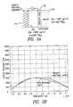
- FIG. 2Ais a schematic cross-sectional view of a non-resonant polymer transducer structure having a conventional matching layer
- FIG. 2Bis a graphical representation of transducer output as a function of frequency for the transducer of FIG. 2A with and without a matching layer;
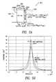
- FIG. 3Ais a schematic cross-sectional view of a resonant PZT transducer structure having a conventional matching layer
- FIG. 3Bis a graphical representation of transducer output as a function of frequency for the transducer of FIG. 3A with and without a matching layer;
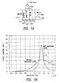
- FIG. 4Ais a schematic cross-sectional view of a resonant polymer transducer structure having a conventional matching layer
- FIG. 4Bis a graphical representation of transducer output as a function of frequency for the transducer of FIG. 4A with and without a matching layer;
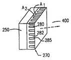
- FIG. 5Ais a schematic cross-sectional view of an ultrasonic transducer utilizing a layer of PZT for generating an acoustic wave into a transmission medium via a matching layer having impedance characteristics in accordance with an embodiment of the present invention
- FIG. 5Bis a graphical representation of transducer output as a function of frequency for the transducer of FIG. 5A with and without a matching layer;
- FIG. 6Ais a schematic cross-sectional view of an ultrasonic transducer utilizing a layer of copolymer for generating an acoustic wave into a transmission medium via a matching layer having impedance characteristics in accordance with an embodiment of the present invention
- FIG. 6Bis a graphical representation of transducer output as a function of frequency for the transducer of FIG. 6A with and without a matching layer;
- FIG. 7Ais a schematic cross-sectional view of an ultrasonic transducer utilizing a double layer polymer for generating an acoustic wave into a transmission medium via a matching layer having impedance characteristics in accordance with an embodiment of the present invention
- FIG. 7Bis a graphical representation of transducer output as a function of frequency for the transducer of FIG. 7A with and without a matching layer;
- FIG. 8Ais a schematic cross-sectional view of an ultrasonic transducer utilizing a dual matching layer structure in accordance with an embodiment of the present invention
- FIG. 8Bis a graphical representation of transducer output as a function of frequency for the transducer of FIG. 8A with and without a matching layer;
- FIG. 9Adepicts an exemplary embodiment of the dual layer matching layer structure illustrating relative thicknesses and impedances of the matching layer according to the present invention
- FIG. 9Bis a graphical representation of real and imaginary impedances as a function of frequency of the dual layer matching structure of FIG. 9A;
- FIG. 10Adepicts an exemplary embodiment of the dual layer matching layer structure similar to FIG. 9A;
- FIG. 10Bis a graphical representation of real and imaginary impedances as a function of frequency and variation in thickness of the dual layer matching structure of FIG. 10A;
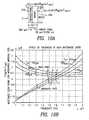
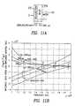
- FIG. 11Adepicts an exemplary embodiment of the dual layer matching layer structure similar to FIG. 10A;
- FIG. 11Bis a graphical representation of real and imaginary impedances as a function of frequency and variation in thickness of the dual layer matching structure of FIG. 11A;
- FIG. 12Adepicts an exemplary embodiment of the dual layer matching layer structure similar to FIG. 11A;
- FIG. 12Bis a graphical representation of transducer output as a function of frequency for the transducer of FIG. 12A with and without a matching layer;
- FIGS. 13A and 13Bdepict respectively, perspective and side views of an ultrasonic transducer having a slotted matched array structure according to the present invention.
- Piezoelectric, electrostrictive or relaxor type materials for thickness mode transducerscan be crystals of LiNbO 3 , quartz, LiTaO 3 , TGS, ZnO, among others, or ceramic of PZT, PMN, PMN-PT material, or polymer films of PVDF or PVDF-TrFE.
- the propagation medium for the ultrasonic energyis a liquid such as water, water solution, organic liquid such as alcohol, oil, petroleum and the like. Also, solids are sometimes used as a propagation medium. While the present invention will work for any material mentioned above, examples of PZT and PVDF-TrFE copolymers will be presented and discussed herein.
- FIG. 1Aillustrates the basic structure of a non-resonant ultrasonic transducer for transmitting directly into a propagation medium without employing a matching layer.
- FIG. 1Billustrates an ultrasonic transducer having an impedance matched matching layer for acoustically coupling the transducer to the radiation medium.
- the acoustic impedance of a matching layeris chosen to satisfy Eq. (1) and the matching layer thickness is chosen to be equal to one-quarter of the wavelength in the material.
- Eq(1)represents the best matching condition where there is no reflection from the transducer surface and therefore generally it is believed that output wave amplitude becomes larger than the mismatched case of no matching layer.
- a front matching layer 180(FIG. 1B) satisfying Eq(1) is disposed between the PZT material and aqueous radiation medium 190 .
- a 12 volt source potential 195is applied across piezo layer 150 .
- FIG. 1Cdepicts simulation curves 35 , 37 for the two cases depicted in FIGS. 1A and 1B, with and without matching layers, respectively, using Mason model simulation for a transmitter.
- An ultrasonic receiveralso has similar performance.
- the output or sensitivityis higher for the case where a matching layer (using a condition of Eq(1) inserted).
- FIGS. 3A and Billustrate the structure associated with a resonant transducer using the conventional matching layer impedance, and a plot of transmitter output as a function of frequency for a resonant transducer with and without the conventional matching layer respectively.
- a generated waveis reflected at the front 150 A and back surfaces 150 B and travels back and forth.
- the wave amplitudebecomes stronger, defining a resonance frequency f r .
- the resonance conditionis satisfied when the thickness t of piezoelectric layer 150 equals half of the wavelength.
- PVDF-TrFE copolymeror PVDF layer 150 .
- a very heavy and stiff (high impedance) materialsuch as metal, ceramic, porcelain, or glass is used as backing 130 .
- the function of the backingis to reflect the backward wave to forward.
- the thickness of the copolymer layeris one-quarter wavelength.
- PZTwhich has very high impedance, (and other higher impedance material) such layer is not available so that quarter wavelength resonance is not possible.
- impedance at resonanceis given by:
- Q pis the mechanical quality factor (inverse of elastic loss factor) of piezoelectric material and is 75 for PZT-5A and 15 for PVDF-TrFE copolymer. Note here Z p,R does not include resonance frequency which is determined by thickness.
- Z p,Rbecause the impedance of the transducer at resonance is Z p,R but not Z p , the best matching condition is given by Eq(1) using Z p,R replaced for Z p .
- Z p,R and Z p of PZT-5A and PVDF-TrFE and also waterare represented as follows:
- FIGS. 5B and 6Bshow results of simulations for respective transducer structures of PZT-5A and PVDF-TrFE shown in FIGS. 5A, 6 A, where the above Z m acoustic impedance value for the matching layer is used.
- Z macoustic impedance value for the matching layer.
- Above values of Z mare not available for conventional material, but rubber or polymers with very tiny bubbles inclusion is suitable. Note that, throughout the remainder of the drawings, like reference numerals are used to indicate like parts.
- a resonant transducer structure 200comprises a vibrator body 250 of piezoelectric material PZT-5A which is coupled at respective front 250 A and back 250 B conductive surfaces via electrode wires 300 A, 300 B connected to generate a voltage difference across the piezoelectric body to excite the body and generate the acoustic wave 330 at a resonant frequency f r for transmission to radiation medium 400 (e.g. water).
- radiation medium 400e.g. water
- an air backing 500is used adjacent back surface 250 B.
- Matching layer 270is disposed adjacent front surface 250 A and bonded thereto at a first surface of the matching layer and to radiation medium 400 at a second surface opposite the first surface.
- PZT-5A layer 250has an acoustic impedance Z p,R associated with a resonant frequency (of, for example 1 MHZ) which is lower than the acoustic impedance Z R associated with the radiation medium 400 .
- the matching layer 270acoustically matches PZT ceramic layer 250 with radiation medium 400 and has an acoustic impedance value Z m which lies between the “low” impedance PZT material at resonance and the “high” impedance radiation medium.
- the matching layer shown in FIG. 5Ahas a width t m of approximately of 0.894 mm and an acoustic impedance Z m of 1.03 ⁇ 10 6 kg/m 2 sec.
- Transmitted output poweris a function of the resonance frequency associated with the structure and is depicted in FIG. 5B for the structure of FIG. 5 A. As shown in FIG.
- curve 10is associated with the resonant transducer utilizing the matching layer acoustic impedance criteria of less than the radiation medium.
- Curve 20represents the transmitter power output as the function of frequency without employing a matching layer. As can be seen, power output is significantly increased while the narrowband frequency range is reduced.
- Power source 350operates to generate a voltage of approximately 20 volts rms to cause the transducer to be operative in a continuous wave mode.
- FIG. 6Ashows a variation of the resonant transducer and novel matching layer structure which employs a copolymer material vibrating body 250 .
- the thickness t1 associated with the copolymer layer 250is approximately 0.7 mm while thickness t2 associated with a matching layer 270 is 0.398 mm.
- the copolymer layeris excited by a potential of 800 volts rms across its front and back surfaces for transmitting the cw acoustic waves into water medium 400 .
- FIG. 6Billustrates the increase in output power and reduction in bandwidth associated with the resonant transducer polymer with the matching layer (curve 12 ) depicted in FIG. 6A versus a resonant transducer without a corresponding matching layer (curve 14 ).
- FIG. 7Ashows an embodiment of a resonated transducer having a double polymer layer vibrating body structure 250 comprising resonating layers 252 and 254 .
- Vibrating layer 252comprises a copolymer PVDF-TrFE of a first thickness t1 which is bonded to a second layer 254 of mylar material having a thickness t2 of approximately 0.25 mm.
- Copolymer layer 252is bonded at a second surface opposite the first surface to a backing layer 510 of alumina having a very high impedance of 4.2 ⁇ 10 7 Kg/m 2 sec.
- the alumina backing layerpreferably has a thickness t 3 of approximately 0.7 mm.
- copolymer layer 252is excited by a potential source of 700V rms applied at electrodes disposed on the first and second opposing surfaces to cause generation of the acoustic wave 330 into water medium 400 .
- the copolymer layer 252is thinner than one quarter wavelength (0.153 ⁇ ) and the mylar layer 254 (0.1488 ⁇ ) is added to make the total polymer thickness roughly equal to one quarter of the wavelength.
- the best impedance of the front matching layer 270is somewhat different from Eq. (2) and (3) because of the more complicated structure. Using Mason model simulation, the best condition of matching layer is determined so as to obtain highest output power. In the case of FIG. 7A, the best thickness of the matching layer is less than quarter wavelength (approximately 0.15 of wavelength).
- FIG. 7Bprovides a graphical illustration of the output power as a function of resonant frequency associated with the resonant transducer structure of FIG. 7 A.
- curve 15the power output at the resonant frequency using the matching layer structure shown in FIG. 7A is substantially greater than curve 17 which illustrates a resonant transducer which does not employ the novel matching layer.
- matching layer 270has an acoustic impedance value less than the acoustic impedance associated with the water medium 400 but greater than that associated with the double layer polymer resonant structure, for providing the high output power at narrowband frequency as depicted in FIG. 7 B.
- the matching layer 270should therefore be constructed of low impedance material lower than that of water medium 400 .
- the acoustic impedance of polyurethane materialis 1.9 ⁇ 10 6 Kg/m 2 s. This does not vary for different types of polyurethane with Shore hardness ranging from 20A to 85A.
- Silicone rubber materialhas an acoustic impedance of 1.3 ⁇ 10 6 Kg/m 2 s and natural rubber is 1.7 ⁇ 10 6 Kg/m 2 s. These values are too high for the present application. Rather, a matching layer having an acoustic impedance which is substantially less than that of water (1.5 ⁇ 10 6 Kg/m 2 s) is needed. This requirement is difficult or practically may not be possible to obtain in naturally occurring materials. Therefore one may have to make artificially low impedance material structures.
- One such type of material for use as a matching layer having an impedance lower than watercomprises bubble included materials.
- These low density and low velocity materialscan be synthesized in various ways.
- An exampleis bubble inclusion in soft rubber type materials.
- the size of the bubbleshould be small because the acoustic wave is scattered by large bubbles, resulting in greater acoustic loss.
- the bubble sizeshould be approximately two orders of magnitude smaller than the wavelength. If the size is one order smaller than the wavelength, the loss will be significant. In the case of a 1 MHZ resonant frequency, a bubble size of ⁇ 0.01 mm or less is sufficient. Also, uniform dispersion of bubbles is necessary in order to avoid additional loss.
- Such materialscan be synthesized by combination of chemical reaction, heating, cooling and gas introduction.
- Such examplesinclude: (1) sintering of thermo plastic fine powder at a temperature for critical melt (2) gas emission from fine particles in a high temperature and cooling (3) chemical reaction of fine powder material with liquid for gas emission (4) high speed whipping of high viscosity material (like ice cream) (5) fine bubble formation from nozzle into a high viscosity liquid and cooling, etc are possible.
- the host materialshould have low impedance such as polyurethane or rubbery materials.
- the matching layer 270may comprise a narrow strip 280 of rubbery material for acoustically matching piezoelectric layer 250 with radiation medium 400 .
- the acoustic impedancebecomes smaller, and therefore an array of narrow long strips 280 vertical to the transducer surface and having an air space or gap 282 between each of the strips is provided. This allows for the averaged acoustic impedance of the matching layer to be lower than that of water.
- the materialshould be a polyurethane or rubber material.
- the front surface and side of the matching layeris covered by an encapsulating layer 290 which keeps air inside.
- the space or gap 282 and also the width of the strip 280should be as small as possible because a thin encapsulating layer tends to have flexural vibration, which decreases the output power.
- the criterion for whether or not flexural wave motion influences the transduceris whether is that quarter wavelength of the flexural wave is larger than the space between strips. Since the wavelength of flexural wave is larger for a thicker plate, it is possible to make the encapsulating layer thick. However, in this case, the effect of the thickness has to be explicitly taken into account during the design process.
- any transducer at a strong resonance conditionhas very low impedance, less than that of water, so that a rubbery material with small fractional area of cross section is used for the matching section.
- a dual layer matching layer structureis provided for reducing the impedance as seen from the front surface of the transducer body to a value less than that of the radiation medium.
- the resonated transducer depicted thereincomprises the double layer polymer resonator section 250 consisting of a PVDF-TrFE layer 252 of thickness t 1 of 0.23 mm bonded at a first surface to mylar layer 254 of thickness t 2 of 0.25 mm.
- Layers 272 and 274operate to define the matching layer with polyurethane layer 272 sandwiched between mylar layers 254 (part of the resonating body) and 274 (outer portion of matching layer).
- Layer 274is defined as the outer layer while layer 272 is defined as the inner layer of matching layer 270 .
- Outer layer 274 of mylaris also adjacent and in contact with the radiation medium 400 .
- a high impedance backing layer 510 of aluminais bonded to a second surface of PVDF-TrFE layer 252 .
- the acoustic impedance of the inner side layer 272does not have to be lower than that of water medium 400 , but it should be relatively lower than that of the outer side material 274 .
- the inner low impedance material layer 272can also be natural rubber (which is somewhat higher than water) which is sufficient to provide a combined effective input impedance having a value much lower than water.
- Other possibilities of inner materialinclude silicone rubber polybutadiene, polyisoprene or polychloroprene.
- the impedance Z as seen from the Point A to output sideis actually loaded to the transducer material 252 , 254 impedance at resonance (0.1-0.7 ⁇ 10 6 Kg/m 2 s). Therefore, this Z value should be matched to these resonance values.
- FIGS. 10A, 11 A and 12 Aeach depict differing layer thicknesses and materials which comprise the dual structure matching layer having an effective impedance less than that of the radiation medium 400 .
- FIGS. 9B, 10 B and 11 BThe Z values are plotted as a function of frequency and shown in FIGS. 9B, 10 B and 11 B, each respectively corresponding to the structures depicted in FIGS. 9A, 10 A and 11 A.
- the imaginary partvaries from negative to positive and crosses zero at a particular frequency. Therefore, Z becomes a purely real number at that given frequency.
- the zero-crossing frequencyshould be chosen to be equal to the resonance frequency of the transducer.
- a higher impedance of the outer layeris thus converted to a lower impedance value. In this manner, alumina has higher impedance than Mylar but the effective impedance Z becomes lower.
- FIG. 10Ain order to choose the zero-crossing frequency, the thickness of outer plate 274 is varied. This, in turn, influences the effective Z values.
- FIG. 10Bprovides a graphical representation of the impedance z seen from the low impedance material side as a function of frequency, and it illustrates the effect of thickness of the high impedance layer. As can be seen from an analysis of FIG. 10B, the thicker the outer plate 274 , the lower the effective impedance Z at the zero crossing frequency (Points A, B, C) is obtained. Also, the thicker the outer plate, the lower zero crossing frequency is seen (Points D, E, F).
- FIG. 12Bshows the output power curves with (curve 22 ) and without (curve 24 ) a double matching layer for the PZT-4 transducer illustrated in FIG. 12 A.
- the effect of the matching layeris remarkable for power output.
- the transducer structure shown thereincomprises a matching layer consisting of a stainless steel outer layer 274 , and an inner polyurethane layer 272 which is coupled at first surface to acoustically match resonating layer 250 comprising PZT-4 material.
- a source potential of 12 voltsis connected via electrodes to the front and back surfaces of PZT-4 layer 250 for providing excitation of the transducer.
- the PZT-4 layeris approximately 1.35 mm thick.
- Polyurethane inner layer 274has a thickness of 360 ⁇ m while stainless steel layer 274 has a thickness of 75 ⁇ m.
- An air backingis used in the structure depicted in FIG. 12 A and is in contact engagement with the back surface of PZT-4 layer 250 .
- the layer 250 of PZT-4 material illustrated in FIG. 12Ahas significantly different characteristics than that of the copolymer layer vibrating body 250 depicted, for example, in FIGS. 7A and 8A.
- PZT materialrepresents a very heavy material in comparison to the soft, relatively lightweight characteristics associated with copolymer layers.
- the voltage applied to the PZT material for operating in continuous wave mode and resonating the transducer, as depicted in the drawings and as described herein,is quite different from that of the polymer layer.
- the variation of parameters associated with the matching layerdoes not have a very serious effect on the power output curves.
- the peak outputis reduced by 12/20% and peak frequency varies by ⁇ /+1%. Such is the case for FIGS. 12A-B.
- the impedance of the layer closer to the transduceri.e. high impedance
- the impedance of the region (i.e. layer) closer to the radiation water medium (low impedance)is close to that of water.
- the purpose behind these patentsis to make the useful frequency band broader.
- Their basic premiseis that the transducer material has high impedance while water is low impedance. To couple from high impedance to low impedance effectively without reflection, the conventional method is a gradual or step-wise change of impedance from high to low value.
- the present inventionuses a structure of low impedance material, which can be lower than the transducer's material impedance and is in contact with the transducer body.
- a high impedance materialis at the outside, and as a result, the frequency band becomes narrower and output power increases.
Landscapes
- Engineering & Computer Science (AREA)
- Physics & Mathematics (AREA)
- Acoustics & Sound (AREA)
- Multimedia (AREA)
- Mechanical Engineering (AREA)
- Transducers For Ultrasonic Waves (AREA)
Abstract
Description
| PZT-5A | PZT-4 | PVDF-TrFE | Water | ||
| QP= 75 | QP= 500 | QP= 15 | — | |
 | 7.14 × 10⁵ | 9.6 × 10⁴ | 4.4 × 10⁵ | — |
 | — | — | 2.2 × 10⁵ | — |
| ZP | 3.57 × 10⁷ | 3.0 × 10⁷ | 4.23 × 10⁶ | — |
| ZR | — | — | — | 1.5 × 10⁶ |
| Unit: Kg/m2sec | ||||
| PZT-5A | PVDF-TrFE | ||
| Zm | 1.03 × 10⁶ | 7.97 × 10⁵ | Kg/m2sec | ||
Claims (2)
Priority Applications (1)
| Application Number | Priority Date | Filing Date | Title |
|---|---|---|---|
| US09/922,111US6772490B2 (en) | 1999-07-23 | 2001-08-03 | Method of forming a resonance transducer |
Applications Claiming Priority (2)
| Application Number | Priority Date | Filing Date | Title |
|---|---|---|---|
| US09/360,305US6307302B1 (en) | 1999-07-23 | 1999-07-23 | Ultrasonic transducer having impedance matching layer |
| US09/922,111US6772490B2 (en) | 1999-07-23 | 2001-08-03 | Method of forming a resonance transducer |
Related Parent Applications (1)
| Application Number | Title | Priority Date | Filing Date |
|---|---|---|---|
| US09/360,305DivisionUS6307302B1 (en) | 1999-07-23 | 1999-07-23 | Ultrasonic transducer having impedance matching layer |
Publications (2)
| Publication Number | Publication Date |
|---|---|
| US20020027400A1 US20020027400A1 (en) | 2002-03-07 |
| US6772490B2true US6772490B2 (en) | 2004-08-10 |
Family
ID=23417445
Family Applications (2)
| Application Number | Title | Priority Date | Filing Date |
|---|---|---|---|
| US09/360,305Expired - Fee RelatedUS6307302B1 (en) | 1999-07-23 | 1999-07-23 | Ultrasonic transducer having impedance matching layer |
| US09/922,111Expired - LifetimeUS6772490B2 (en) | 1999-07-23 | 2001-08-03 | Method of forming a resonance transducer |
Family Applications Before (1)
| Application Number | Title | Priority Date | Filing Date |
|---|---|---|---|
| US09/360,305Expired - Fee RelatedUS6307302B1 (en) | 1999-07-23 | 1999-07-23 | Ultrasonic transducer having impedance matching layer |
Country Status (3)
| Country | Link |
|---|---|
| US (2) | US6307302B1 (en) |
| AU (1) | AU6956000A (en) |
| WO (1) | WO2001008237A1 (en) |
Cited By (70)
| Publication number | Priority date | Publication date | Assignee | Title |
|---|---|---|---|---|
| US20070010805A1 (en)* | 2005-07-08 | 2007-01-11 | Fedewa Russell J | Method and apparatus for the treatment of tissue |
| US20070038096A1 (en)* | 2005-07-06 | 2007-02-15 | Ralf Seip | Method of optimizing an ultrasound transducer |
| US20070204697A1 (en)* | 2006-03-06 | 2007-09-06 | Denso Corporation | Ultrasonic sensor having vibrator mounted on substrate |
| US20070219448A1 (en)* | 2004-05-06 | 2007-09-20 | Focus Surgery, Inc. | Method and Apparatus for Selective Treatment of Tissue |
| US20070276232A1 (en)* | 2003-05-23 | 2007-11-29 | Arizona Board Of Regents | Piezo Micro-Markers for Ultrasound Medical Diagnostics |
| US20080077056A1 (en)* | 2006-09-21 | 2008-03-27 | Shuhei Kagosaki | HIFU probe for treating tissue with in-line degassing of fluid |
| US7522962B1 (en) | 2004-12-03 | 2009-04-21 | Remon Medical Technologies, Ltd | Implantable medical device with integrated acoustic transducer |
| US7580750B2 (en) | 2004-11-24 | 2009-08-25 | Remon Medical Technologies, Ltd. | Implantable medical device with integrated acoustic transducer |
| US7634318B2 (en) | 2007-06-14 | 2009-12-15 | Cardiac Pacemakers, Inc. | Multi-element acoustic recharging system |
| US20110050039A1 (en)* | 2009-09-01 | 2011-03-03 | Measurement Specialties | Multilayer acoustic impedance converter for ultrasonic transducers |
| US7948148B2 (en) | 1997-12-30 | 2011-05-24 | Remon Medical Technologies Ltd. | Piezoelectric transducer |
| US8038631B1 (en) | 2005-06-01 | 2011-10-18 | Sanghvi Narendra T | Laparoscopic HIFU probe |
| US8235902B2 (en) | 2007-09-11 | 2012-08-07 | Focus Surgery, Inc. | System and method for tissue change monitoring during HIFU treatment |
| WO2012141891A1 (en)* | 2011-04-12 | 2012-10-18 | Rensselaer Polytechnic Institute | Adaptive system for efficient transmission of power and data through acoustic media |
| US8548592B2 (en) | 2006-07-21 | 2013-10-01 | Cardiac Pacemakers, Inc. | Ultrasonic transducer for a metallic cavity implanted medical device |
| US8825161B1 (en) | 2007-05-17 | 2014-09-02 | Cardiac Pacemakers, Inc. | Acoustic transducer for an implantable medical device |
| US9283410B2 (en) | 2004-10-06 | 2016-03-15 | Guided Therapy Systems, L.L.C. | System and method for fat and cellulite reduction |
| US9283409B2 (en) | 2004-10-06 | 2016-03-15 | Guided Therapy Systems, Llc | Energy based fat reduction |
| US9320537B2 (en) | 2004-10-06 | 2016-04-26 | Guided Therapy Systems, Llc | Methods for noninvasive skin tightening |
| US9421029B2 (en) | 2004-10-06 | 2016-08-23 | Guided Therapy Systems, Llc | Energy based hyperhidrosis treatment |
| US9427600B2 (en) | 2004-10-06 | 2016-08-30 | Guided Therapy Systems, L.L.C. | Systems for treating skin laxity |
| US9427601B2 (en) | 2004-10-06 | 2016-08-30 | Guided Therapy Systems, Llc | Methods for face and neck lifts |
| US9440096B2 (en) | 2004-10-06 | 2016-09-13 | Guided Therapy Systems, Llc | Method and system for treating stretch marks |
| US9510802B2 (en) | 2012-09-21 | 2016-12-06 | Guided Therapy Systems, Llc | Reflective ultrasound technology for dermatological treatments |
| US9694212B2 (en) | 2004-10-06 | 2017-07-04 | Guided Therapy Systems, Llc | Method and system for ultrasound treatment of skin |
| US9827449B2 (en) | 2004-10-06 | 2017-11-28 | Guided Therapy Systems, L.L.C. | Systems for treating skin laxity |
| US10101814B2 (en) | 2015-02-20 | 2018-10-16 | Ultrahaptics Ip Ltd. | Perceptions in a haptic system |
| US10101811B2 (en) | 2015-02-20 | 2018-10-16 | Ultrahaptics Ip Ltd. | Algorithm improvements in a haptic system |
| US10268275B2 (en) | 2016-08-03 | 2019-04-23 | Ultrahaptics Ip Ltd | Three-dimensional perceptions in haptic systems |
| US10281567B2 (en) | 2013-05-08 | 2019-05-07 | Ultrahaptics Ip Ltd | Method and apparatus for producing an acoustic field |
| US10326072B2 (en) | 2015-05-11 | 2019-06-18 | Measurement Specialties, Inc. | Impedance matching layer for ultrasonic transducers with metallic protection structure |
| US10420960B2 (en) | 2013-03-08 | 2019-09-24 | Ulthera, Inc. | Devices and methods for multi-focus ultrasound therapy |
| US10444842B2 (en) | 2014-09-09 | 2019-10-15 | Ultrahaptics Ip Ltd | Method and apparatus for modulating haptic feedback |
| US10497358B2 (en) | 2016-12-23 | 2019-12-03 | Ultrahaptics Ip Ltd | Transducer driver |
| US10531212B2 (en) | 2016-06-17 | 2020-01-07 | Ultrahaptics Ip Ltd. | Acoustic transducers in haptic systems |
| US10537304B2 (en) | 2008-06-06 | 2020-01-21 | Ulthera, Inc. | Hand wand for ultrasonic cosmetic treatment and imaging |
| US10603521B2 (en) | 2014-04-18 | 2020-03-31 | Ulthera, Inc. | Band transducer ultrasound therapy |
| US10755538B2 (en) | 2016-08-09 | 2020-08-25 | Ultrahaptics ilP LTD | Metamaterials and acoustic lenses in haptic systems |
| US10818162B2 (en) | 2015-07-16 | 2020-10-27 | Ultrahaptics Ip Ltd | Calibration techniques in haptic systems |
| US10864385B2 (en) | 2004-09-24 | 2020-12-15 | Guided Therapy Systems, Llc | Rejuvenating skin by heating tissue for cosmetic treatment of the face and body |
| US10911861B2 (en) | 2018-05-02 | 2021-02-02 | Ultrahaptics Ip Ltd | Blocking plate structure for improved acoustic transmission efficiency |
| US10921890B2 (en) | 2014-01-07 | 2021-02-16 | Ultrahaptics Ip Ltd | Method and apparatus for providing tactile sensations |
| US10943578B2 (en) | 2016-12-13 | 2021-03-09 | Ultrahaptics Ip Ltd | Driving techniques for phased-array systems |
| US11098951B2 (en) | 2018-09-09 | 2021-08-24 | Ultrahaptics Ip Ltd | Ultrasonic-assisted liquid manipulation |
| US11169610B2 (en) | 2019-11-08 | 2021-11-09 | Ultraleap Limited | Tracking techniques in haptic systems |
| US11189140B2 (en) | 2016-01-05 | 2021-11-30 | Ultrahaptics Ip Ltd | Calibration and detection techniques in haptic systems |
| US11207548B2 (en) | 2004-10-07 | 2021-12-28 | Guided Therapy Systems, L.L.C. | Ultrasound probe for treating skin laxity |
| US11224895B2 (en) | 2016-01-18 | 2022-01-18 | Ulthera, Inc. | Compact ultrasound device having annular ultrasound array peripherally electrically connected to flexible printed circuit board and method of assembly thereof |
| US11235179B2 (en) | 2004-10-06 | 2022-02-01 | Guided Therapy Systems, Llc | Energy based skin gland treatment |
| US11241218B2 (en) | 2016-08-16 | 2022-02-08 | Ulthera, Inc. | Systems and methods for cosmetic ultrasound treatment of skin |
| US11338156B2 (en) | 2004-10-06 | 2022-05-24 | Guided Therapy Systems, Llc | Noninvasive tissue tightening system |
| US11360546B2 (en) | 2017-12-22 | 2022-06-14 | Ultrahaptics Ip Ltd | Tracking in haptic systems |
| US11374586B2 (en) | 2019-10-13 | 2022-06-28 | Ultraleap Limited | Reducing harmonic distortion by dithering |
| US11378997B2 (en) | 2018-10-12 | 2022-07-05 | Ultrahaptics Ip Ltd | Variable phase and frequency pulse-width modulation technique |
| US11531395B2 (en) | 2017-11-26 | 2022-12-20 | Ultrahaptics Ip Ltd | Haptic effects from focused acoustic fields |
| US11553295B2 (en) | 2019-10-13 | 2023-01-10 | Ultraleap Limited | Dynamic capping with virtual microphones |
| US11550395B2 (en) | 2019-01-04 | 2023-01-10 | Ultrahaptics Ip Ltd | Mid-air haptic textures |
| US11704983B2 (en) | 2017-12-22 | 2023-07-18 | Ultrahaptics Ip Ltd | Minimizing unwanted responses in haptic systems |
| US11715453B2 (en) | 2019-12-25 | 2023-08-01 | Ultraleap Limited | Acoustic transducer structures |
| US11724133B2 (en) | 2004-10-07 | 2023-08-15 | Guided Therapy Systems, Llc | Ultrasound probe for treatment of skin |
| US11816267B2 (en) | 2020-06-23 | 2023-11-14 | Ultraleap Limited | Features of airborne ultrasonic fields |
| US11842517B2 (en) | 2019-04-12 | 2023-12-12 | Ultrahaptics Ip Ltd | Using iterative 3D-model fitting for domain adaptation of a hand-pose-estimation neural network |
| US11883688B2 (en) | 2004-10-06 | 2024-01-30 | Guided Therapy Systems, Llc | Energy based fat reduction |
| US11886639B2 (en) | 2020-09-17 | 2024-01-30 | Ultraleap Limited | Ultrahapticons |
| US11944849B2 (en) | 2018-02-20 | 2024-04-02 | Ulthera, Inc. | Systems and methods for combined cosmetic treatment of cellulite with ultrasound |
| US12023499B2 (en) | 2014-03-17 | 2024-07-02 | Arizona Board Of Regents On Behalf Of Arizona State University | Methods and systems for measuring tissue impedance and monitoring PVD treatment using neuro-implants with improved ultrasound powering |
| US12076591B2 (en) | 2018-01-26 | 2024-09-03 | Ulthera, Inc. | Systems and methods for simultaneous multi-focus ultrasound therapy in multiple dimensions |
| US12102473B2 (en) | 2008-06-06 | 2024-10-01 | Ulthera, Inc. | Systems for ultrasound treatment |
| US12373033B2 (en) | 2019-01-04 | 2025-07-29 | Ultrahaptics Ip Ltd | Mid-air haptic textures |
| US12377293B2 (en) | 2019-07-15 | 2025-08-05 | Ulthera, Inc. | Systems and methods for measuring elasticity with imaging of ultrasound multi-focus shearwaves in multiple dimensions |
Families Citing this family (37)
| Publication number | Priority date | Publication date | Assignee | Title |
|---|---|---|---|---|
| US6835178B1 (en)* | 1999-06-23 | 2004-12-28 | Hologic, Inc. | Ultrasonic bone testing with copolymer transducers |
| US6707230B2 (en)* | 2001-05-29 | 2004-03-16 | University Of North Carolina At Charlotte | Closed loop control systems employing relaxor ferroelectric actuators |
| EP1477778A1 (en)* | 2002-01-28 | 2004-11-17 | Matsushita Electric Industrial Co., Ltd. | Acoustic matching layer, ultrasonic transmitter/receiver, and ultrasonic flowmeter |
| JP4222467B2 (en)* | 2002-04-18 | 2009-02-12 | テイカ株式会社 | Composite piezoelectric material and manufacturing method thereof |
| JP3856380B2 (en)* | 2002-04-26 | 2006-12-13 | テイカ株式会社 | Composite piezoelectric vibrator and manufacturing method thereof |
| US6888291B2 (en)* | 2002-10-31 | 2005-05-03 | The Boeing Company | Electrical system for electrostrictive bimorph actuator |
| JP4004396B2 (en)* | 2002-12-19 | 2007-11-07 | オリンパス株式会社 | Ultrasonic transducer |
| US7062972B2 (en)* | 2003-07-21 | 2006-06-20 | Horiba Instruments, Inc. | Acoustic transducer |
| US7021145B2 (en)* | 2003-07-21 | 2006-04-04 | Horiba Instruments, Inc | Acoustic transducer |
| KR100580629B1 (en)* | 2003-11-17 | 2006-05-16 | 삼성전자주식회사 | Skin impedance model that expresses skin impedance response of high frequency band |
| US7124621B2 (en)* | 2004-07-21 | 2006-10-24 | Horiba Instruments, Inc. | Acoustic flowmeter calibration method |
| US7611840B2 (en)* | 2004-08-03 | 2009-11-03 | Agency For Science, Technology And Research | Method and device for the treatment of biological samples |
| US7570998B2 (en)* | 2005-08-26 | 2009-08-04 | Cardiac Pacemakers, Inc. | Acoustic communication transducer in implantable medical device header |
| US7615012B2 (en) | 2005-08-26 | 2009-11-10 | Cardiac Pacemakers, Inc. | Broadband acoustic sensor for an implantable medical device |
| US7912548B2 (en)* | 2006-07-21 | 2011-03-22 | Cardiac Pacemakers, Inc. | Resonant structures for implantable devices |
| JP5155311B2 (en) | 2006-07-21 | 2013-03-06 | カーディアック ペースメイカーズ, インコーポレイテッド | Ultrasonic transmitting / receiving transducer housed in header of implantable medical device |
| US20080125658A1 (en)* | 2006-09-01 | 2008-05-29 | General Electric Company | Low-profile acoustic transducer assembly |
| EP1911530B1 (en)* | 2006-10-09 | 2009-07-22 | Baumer Electric AG | Ultrasound converter with acoustic impedance adjustment |
| WO2009073884A1 (en)* | 2007-12-06 | 2009-06-11 | Measurement Specialties, Inc. | Multilayer backing absorber for ultrasonic transducer |
| US20100249670A1 (en)* | 2009-03-20 | 2010-09-30 | Cutera, Inc. | High-power multiple-harmonic ultrasound transducer |
| KR101173277B1 (en)* | 2010-03-15 | 2012-08-13 | 주식회사 휴먼스캔 | Ultrasound probe using rear acoustic matching layer |
| EP2662154B1 (en) | 2011-02-15 | 2017-03-15 | Halliburton Energy Services, Inc. | Acoustic transducer with impedance matching layer |
| US8564177B2 (en) | 2011-09-09 | 2013-10-22 | Dvx, Llc | Piezopolymer transducer with matching layer |
| US9166141B2 (en) | 2011-09-09 | 2015-10-20 | Dvx, Llc | Process of manufacturing a piezopolymer transducer with matching layer |
| CA2861923A1 (en) | 2012-01-30 | 2013-08-08 | Piezotech, Llc | Pulse-echo acoustic transducer |
| GB201207045D0 (en) | 2012-04-23 | 2012-06-06 | Hiwave Technologies Uk Ltd | Transducers with improved impedance matching |
| CN104883979B (en)* | 2012-12-26 | 2017-05-03 | 富士胶片株式会社 | Single-layer piezoelectric sheet type ultrasonic probe and manufacturing method thereof |
| JP6314412B2 (en)* | 2013-10-11 | 2018-04-25 | セイコーエプソン株式会社 | Ultrasonic device and ultrasonic diagnostic apparatus |
| US11723625B2 (en)* | 2014-04-25 | 2023-08-15 | Transducerworks, Llc | Acoustic lens of enhanced wear resistance |
| FR3032524B1 (en)* | 2015-02-10 | 2017-03-24 | Yzatec | ULTRASOUND TRANSDUCER, ITS MOUNTING METHOD AND FLOWMETER COMPRISING AT LEAST ONE SUCH TRANSDUCER |
| AU2016311449B2 (en) | 2015-08-27 | 2019-01-03 | Balance Ophthalmics, Inc. | Eye-related intrabody pressure identification and modification |
| JP6764281B2 (en)* | 2016-08-09 | 2020-09-30 | 太陽誘電株式会社 | Gas sensor |
| DE102018206937A1 (en)* | 2018-05-04 | 2019-11-07 | Fraunhofer-Gesellschaft zur Förderung der angewandten Forschung e.V. | An impedance matching device, a converter device, and a method of manufacturing an impedance matching device |
| KR20250069675A (en) | 2018-08-09 | 2025-05-19 | 밸런스 오프탈믹스, 인크. | Apparatus and methods to adjust ocular blood flow |
| US11664779B2 (en) | 2019-07-03 | 2023-05-30 | Toyota Motor Engineering & Manufacturing North America, Inc. | Acoustic impedance matching with bubble resonators |
| WO2022238326A1 (en)* | 2021-05-10 | 2022-11-17 | Koninklijke Philips N.V. | Graded acoustic matching layers |
| CN119310189A (en)* | 2023-07-12 | 2025-01-14 | 华为技术有限公司 | Ultrasonic detection device and fingerprint recognition device |
Citations (13)
| Publication number | Priority date | Publication date | Assignee | Title |
|---|---|---|---|---|
| US2803129A (en)* | 1951-05-28 | 1957-08-20 | Council Scient Ind Res | Apparatus for testing of elastic materials |
| US3925692A (en)* | 1974-06-13 | 1975-12-09 | Westinghouse Electric Corp | Replaceable element ultrasonic flowmeter transducer |
| US3935484A (en)* | 1974-02-25 | 1976-01-27 | Westinghouse Electric Corporation | Replaceable acoustic transducer assembly |
| US4166967A (en)* | 1976-10-19 | 1979-09-04 | Hans List | Piezoelectric resonator with acoustic reflectors |
| US4211948A (en) | 1978-11-08 | 1980-07-08 | General Electric Company | Front surface matched piezoelectric ultrasonic transducer array with wide field of view |
| US4211949A (en)* | 1978-11-08 | 1980-07-08 | General Electric Company | Wear plate for piezoelectric ultrasonic transducer arrays |
| US4507582A (en) | 1982-09-29 | 1985-03-26 | New York Institute Of Technology | Matching region for damped piezoelectric ultrasonic apparatus |
| US4578611A (en)* | 1984-03-14 | 1986-03-25 | Rolls-Royce Limited | Piezoelectric stress wave transducer with boron nitride piezo support |
| US4672591A (en) | 1985-01-21 | 1987-06-09 | Siemens Aktiengesellschaft | Ultrasonic transducer |
| US4771205A (en)* | 1983-08-31 | 1988-09-13 | U.S. Philips Corporation | Ultrasound transducer |
| US5329682A (en)* | 1991-02-07 | 1994-07-19 | Siemens Aktiengesellschaft | Method for the production of ultrasound transformers |
| US5332943A (en)* | 1993-10-21 | 1994-07-26 | Bhardwaj Mahesh C | High temperature ultrasonic transducer device |
| US5541468A (en)* | 1994-11-21 | 1996-07-30 | General Electric Company | Monolithic transducer array case and method for its manufacture |
- 1999
- 1999-07-23USUS09/360,305patent/US6307302B1/ennot_activeExpired - Fee Related
- 2000
- 2000-07-18WOPCT/US2000/040414patent/WO2001008237A1/enactiveApplication Filing
- 2000-07-18AUAU69560/00Apatent/AU6956000A/ennot_activeAbandoned
- 2001
- 2001-08-03USUS09/922,111patent/US6772490B2/ennot_activeExpired - Lifetime
Patent Citations (13)
| Publication number | Priority date | Publication date | Assignee | Title |
|---|---|---|---|---|
| US2803129A (en)* | 1951-05-28 | 1957-08-20 | Council Scient Ind Res | Apparatus for testing of elastic materials |
| US3935484A (en)* | 1974-02-25 | 1976-01-27 | Westinghouse Electric Corporation | Replaceable acoustic transducer assembly |
| US3925692A (en)* | 1974-06-13 | 1975-12-09 | Westinghouse Electric Corp | Replaceable element ultrasonic flowmeter transducer |
| US4166967A (en)* | 1976-10-19 | 1979-09-04 | Hans List | Piezoelectric resonator with acoustic reflectors |
| US4211948A (en) | 1978-11-08 | 1980-07-08 | General Electric Company | Front surface matched piezoelectric ultrasonic transducer array with wide field of view |
| US4211949A (en)* | 1978-11-08 | 1980-07-08 | General Electric Company | Wear plate for piezoelectric ultrasonic transducer arrays |
| US4507582A (en) | 1982-09-29 | 1985-03-26 | New York Institute Of Technology | Matching region for damped piezoelectric ultrasonic apparatus |
| US4771205A (en)* | 1983-08-31 | 1988-09-13 | U.S. Philips Corporation | Ultrasound transducer |
| US4578611A (en)* | 1984-03-14 | 1986-03-25 | Rolls-Royce Limited | Piezoelectric stress wave transducer with boron nitride piezo support |
| US4672591A (en) | 1985-01-21 | 1987-06-09 | Siemens Aktiengesellschaft | Ultrasonic transducer |
| US5329682A (en)* | 1991-02-07 | 1994-07-19 | Siemens Aktiengesellschaft | Method for the production of ultrasound transformers |
| US5332943A (en)* | 1993-10-21 | 1994-07-26 | Bhardwaj Mahesh C | High temperature ultrasonic transducer device |
| US5541468A (en)* | 1994-11-21 | 1996-07-30 | General Electric Company | Monolithic transducer array case and method for its manufacture |
Cited By (161)
| Publication number | Priority date | Publication date | Assignee | Title |
|---|---|---|---|---|
| US7948148B2 (en) | 1997-12-30 | 2011-05-24 | Remon Medical Technologies Ltd. | Piezoelectric transducer |
| US8647328B2 (en) | 1997-12-30 | 2014-02-11 | Remon Medical Technologies, Ltd. | Reflected acoustic wave modulation |
| US8277441B2 (en) | 1997-12-30 | 2012-10-02 | Remon Medical Technologies, Ltd. | Piezoelectric transducer |
| US20070276232A1 (en)* | 2003-05-23 | 2007-11-29 | Arizona Board Of Regents | Piezo Micro-Markers for Ultrasound Medical Diagnostics |
| US8282561B2 (en)* | 2003-05-23 | 2012-10-09 | Arizona Board Of Regents | Piezo micro-markers for ultrasound medical diagnostics |
| US20070219448A1 (en)* | 2004-05-06 | 2007-09-20 | Focus Surgery, Inc. | Method and Apparatus for Selective Treatment of Tissue |
| US11590370B2 (en) | 2004-09-24 | 2023-02-28 | Guided Therapy Systems, Llc | Rejuvenating skin by heating tissue for cosmetic treatment of the face and body |
| US10864385B2 (en) | 2004-09-24 | 2020-12-15 | Guided Therapy Systems, Llc | Rejuvenating skin by heating tissue for cosmetic treatment of the face and body |
| US10328289B2 (en) | 2004-09-24 | 2019-06-25 | Guided Therapy Systems, Llc | Rejuvenating skin by heating tissue for cosmetic treatment of the face and body |
| US9895560B2 (en) | 2004-09-24 | 2018-02-20 | Guided Therapy Systems, Llc | Methods for rejuvenating skin by heating tissue for cosmetic treatment of the face and body |
| US10610705B2 (en) | 2004-10-06 | 2020-04-07 | Guided Therapy Systems, L.L.C. | Ultrasound probe for treating skin laxity |
| US10252086B2 (en) | 2004-10-06 | 2019-04-09 | Guided Therapy Systems, Llc | Ultrasound probe for treatment of skin |
| US11235179B2 (en) | 2004-10-06 | 2022-02-01 | Guided Therapy Systems, Llc | Energy based skin gland treatment |
| US11235180B2 (en) | 2004-10-06 | 2022-02-01 | Guided Therapy Systems, Llc | System and method for noninvasive skin tightening |
| US11400319B2 (en) | 2004-10-06 | 2022-08-02 | Guided Therapy Systems, Llc | Methods for lifting skin tissue |
| US11207547B2 (en) | 2004-10-06 | 2021-12-28 | Guided Therapy Systems, Llc | Probe for ultrasound tissue treatment |
| US11179580B2 (en) | 2004-10-06 | 2021-11-23 | Guided Therapy Systems, Llc | Energy based fat reduction |
| US11167155B2 (en) | 2004-10-06 | 2021-11-09 | Guided Therapy Systems, Llc | Ultrasound probe for treatment of skin |
| US10238894B2 (en) | 2004-10-06 | 2019-03-26 | Guided Therapy Systems, L.L.C. | Energy based fat reduction |
| US10960236B2 (en) | 2004-10-06 | 2021-03-30 | Guided Therapy Systems, Llc | System and method for noninvasive skin tightening |
| US11697033B2 (en) | 2004-10-06 | 2023-07-11 | Guided Therapy Systems, Llc | Methods for lifting skin tissue |
| US11717707B2 (en) | 2004-10-06 | 2023-08-08 | Guided Therapy Systems, Llc | System and method for noninvasive skin tightening |
| US10888718B2 (en) | 2004-10-06 | 2021-01-12 | Guided Therapy Systems, L.L.C. | Ultrasound probe for treating skin laxity |
| US10888717B2 (en) | 2004-10-06 | 2021-01-12 | Guided Therapy Systems, Llc | Probe for ultrasound tissue treatment |
| US10888716B2 (en) | 2004-10-06 | 2021-01-12 | Guided Therapy Systems, Llc | Energy based fat reduction |
| US10610706B2 (en) | 2004-10-06 | 2020-04-07 | Guided Therapy Systems, Llc | Ultrasound probe for treatment of skin |
| US11338156B2 (en) | 2004-10-06 | 2022-05-24 | Guided Therapy Systems, Llc | Noninvasive tissue tightening system |
| US10603523B2 (en) | 2004-10-06 | 2020-03-31 | Guided Therapy Systems, Llc | Ultrasound probe for tissue treatment |
| US9283410B2 (en) | 2004-10-06 | 2016-03-15 | Guided Therapy Systems, L.L.C. | System and method for fat and cellulite reduction |
| US9283409B2 (en) | 2004-10-06 | 2016-03-15 | Guided Therapy Systems, Llc | Energy based fat reduction |
| US9320537B2 (en) | 2004-10-06 | 2016-04-26 | Guided Therapy Systems, Llc | Methods for noninvasive skin tightening |
| US9421029B2 (en) | 2004-10-06 | 2016-08-23 | Guided Therapy Systems, Llc | Energy based hyperhidrosis treatment |
| US9427600B2 (en) | 2004-10-06 | 2016-08-30 | Guided Therapy Systems, L.L.C. | Systems for treating skin laxity |
| US9427601B2 (en) | 2004-10-06 | 2016-08-30 | Guided Therapy Systems, Llc | Methods for face and neck lifts |
| US9440096B2 (en) | 2004-10-06 | 2016-09-13 | Guided Therapy Systems, Llc | Method and system for treating stretch marks |
| US10603519B2 (en) | 2004-10-06 | 2020-03-31 | Guided Therapy Systems, Llc | Energy based fat reduction |
| US9522290B2 (en) | 2004-10-06 | 2016-12-20 | Guided Therapy Systems, Llc | System and method for fat and cellulite reduction |
| US9533175B2 (en) | 2004-10-06 | 2017-01-03 | Guided Therapy Systems, Llc | Energy based fat reduction |
| US9694212B2 (en) | 2004-10-06 | 2017-07-04 | Guided Therapy Systems, Llc | Method and system for ultrasound treatment of skin |
| US9694211B2 (en) | 2004-10-06 | 2017-07-04 | Guided Therapy Systems, L.L.C. | Systems for treating skin laxity |
| US9707412B2 (en) | 2004-10-06 | 2017-07-18 | Guided Therapy Systems, Llc | System and method for fat and cellulite reduction |
| US9713731B2 (en) | 2004-10-06 | 2017-07-25 | Guided Therapy Systems, Llc | Energy based fat reduction |
| US10532230B2 (en) | 2004-10-06 | 2020-01-14 | Guided Therapy Systems, Llc | Methods for face and neck lifts |
| US10525288B2 (en) | 2004-10-06 | 2020-01-07 | Guided Therapy Systems, Llc | System and method for noninvasive skin tightening |
| US9827449B2 (en) | 2004-10-06 | 2017-11-28 | Guided Therapy Systems, L.L.C. | Systems for treating skin laxity |
| US9827450B2 (en) | 2004-10-06 | 2017-11-28 | Guided Therapy Systems, L.L.C. | System and method for fat and cellulite reduction |
| US9833639B2 (en) | 2004-10-06 | 2017-12-05 | Guided Therapy Systems, L.L.C. | Energy based fat reduction |
| US9833640B2 (en) | 2004-10-06 | 2017-12-05 | Guided Therapy Systems, L.L.C. | Method and system for ultrasound treatment of skin |
| US11883688B2 (en) | 2004-10-06 | 2024-01-30 | Guided Therapy Systems, Llc | Energy based fat reduction |
| US9974982B2 (en) | 2004-10-06 | 2018-05-22 | Guided Therapy Systems, Llc | System and method for noninvasive skin tightening |
| US10010721B2 (en) | 2004-10-06 | 2018-07-03 | Guided Therapy Systems, L.L.C. | Energy based fat reduction |
| US10010725B2 (en) | 2004-10-06 | 2018-07-03 | Guided Therapy Systems, Llc | Ultrasound probe for fat and cellulite reduction |
| US10010724B2 (en) | 2004-10-06 | 2018-07-03 | Guided Therapy Systems, L.L.C. | Ultrasound probe for treating skin laxity |
| US10010726B2 (en) | 2004-10-06 | 2018-07-03 | Guided Therapy Systems, Llc | Ultrasound probe for treatment of skin |
| US10046181B2 (en) | 2004-10-06 | 2018-08-14 | Guided Therapy Systems, Llc | Energy based hyperhidrosis treatment |
| US10046182B2 (en) | 2004-10-06 | 2018-08-14 | Guided Therapy Systems, Llc | Methods for face and neck lifts |
| US10265550B2 (en) | 2004-10-06 | 2019-04-23 | Guided Therapy Systems, L.L.C. | Ultrasound probe for treating skin laxity |
| US10245450B2 (en) | 2004-10-06 | 2019-04-02 | Guided Therapy Systems, Llc | Ultrasound probe for fat and cellulite reduction |
| US11724133B2 (en) | 2004-10-07 | 2023-08-15 | Guided Therapy Systems, Llc | Ultrasound probe for treatment of skin |
| US11207548B2 (en) | 2004-10-07 | 2021-12-28 | Guided Therapy Systems, L.L.C. | Ultrasound probe for treating skin laxity |
| US8744580B2 (en) | 2004-11-24 | 2014-06-03 | Remon Medical Technologies, Ltd. | Implantable medical device with integrated acoustic transducer |
| US7580750B2 (en) | 2004-11-24 | 2009-08-25 | Remon Medical Technologies, Ltd. | Implantable medical device with integrated acoustic transducer |
| US7522962B1 (en) | 2004-12-03 | 2009-04-21 | Remon Medical Technologies, Ltd | Implantable medical device with integrated acoustic transducer |
| US8038631B1 (en) | 2005-06-01 | 2011-10-18 | Sanghvi Narendra T | Laparoscopic HIFU probe |
| US20070038096A1 (en)* | 2005-07-06 | 2007-02-15 | Ralf Seip | Method of optimizing an ultrasound transducer |
| WO2007006034A3 (en)* | 2005-07-06 | 2007-06-21 | Focus Surgery Inc | Method of optimizing an ultrasound transducer |
| US20070010805A1 (en)* | 2005-07-08 | 2007-01-11 | Fedewa Russell J | Method and apparatus for the treatment of tissue |
| US7622849B2 (en)* | 2006-03-06 | 2009-11-24 | Denso Corporation | Ultrasonic sensor having vibrator mounted on substrate |
| US20070204697A1 (en)* | 2006-03-06 | 2007-09-06 | Denso Corporation | Ultrasonic sensor having vibrator mounted on substrate |
| US8548592B2 (en) | 2006-07-21 | 2013-10-01 | Cardiac Pacemakers, Inc. | Ultrasonic transducer for a metallic cavity implanted medical device |
| US7559905B2 (en) | 2006-09-21 | 2009-07-14 | Focus Surgery, Inc. | HIFU probe for treating tissue with in-line degassing of fluid |
| US20080077056A1 (en)* | 2006-09-21 | 2008-03-27 | Shuhei Kagosaki | HIFU probe for treating tissue with in-line degassing of fluid |
| US8825161B1 (en) | 2007-05-17 | 2014-09-02 | Cardiac Pacemakers, Inc. | Acoustic transducer for an implantable medical device |
| US8340778B2 (en) | 2007-06-14 | 2012-12-25 | Cardiac Pacemakers, Inc. | Multi-element acoustic recharging system |
| US7634318B2 (en) | 2007-06-14 | 2009-12-15 | Cardiac Pacemakers, Inc. | Multi-element acoustic recharging system |
| US9731141B2 (en) | 2007-06-14 | 2017-08-15 | Cardiac Pacemakers, Inc. | Multi-element acoustic recharging system |
| US8235902B2 (en) | 2007-09-11 | 2012-08-07 | Focus Surgery, Inc. | System and method for tissue change monitoring during HIFU treatment |
| US10537304B2 (en) | 2008-06-06 | 2020-01-21 | Ulthera, Inc. | Hand wand for ultrasonic cosmetic treatment and imaging |
| US11723622B2 (en) | 2008-06-06 | 2023-08-15 | Ulthera, Inc. | Systems for ultrasound treatment |
| US11123039B2 (en) | 2008-06-06 | 2021-09-21 | Ulthera, Inc. | System and method for ultrasound treatment |
| US12102473B2 (en) | 2008-06-06 | 2024-10-01 | Ulthera, Inc. | Systems for ultrasound treatment |
| WO2011028430A1 (en)* | 2009-09-01 | 2011-03-10 | Measurement Specialties, Inc. | Multilayer acoustic impedance converter for ultrasonic transducers |
| US9149838B2 (en) | 2009-09-01 | 2015-10-06 | Measurement Specialties, Inc. | Multilayer acoustic impedance converter for ultrasonic transducers |
| US10483453B2 (en) | 2009-09-01 | 2019-11-19 | Measurement Specialties, Inc. | Method of forming a multilayer acoustic impedance converter for ultrasonic transducers |
| US20110050039A1 (en)* | 2009-09-01 | 2011-03-03 | Measurement Specialties | Multilayer acoustic impedance converter for ultrasonic transducers |
| US8604672B2 (en) | 2009-09-01 | 2013-12-10 | Measurement Specialties, Inc. | Multilayer acoustic impedance converter for ultrasonic transducers |
| US8264126B2 (en) | 2009-09-01 | 2012-09-11 | Measurement Specialties, Inc. | Multilayer acoustic impedance converter for ultrasonic transducers |
| WO2012141891A1 (en)* | 2011-04-12 | 2012-10-18 | Rensselaer Polytechnic Institute | Adaptive system for efficient transmission of power and data through acoustic media |
| US9802063B2 (en) | 2012-09-21 | 2017-10-31 | Guided Therapy Systems, Llc | Reflective ultrasound technology for dermatological treatments |
| US9510802B2 (en) | 2012-09-21 | 2016-12-06 | Guided Therapy Systems, Llc | Reflective ultrasound technology for dermatological treatments |
| US11517772B2 (en) | 2013-03-08 | 2022-12-06 | Ulthera, Inc. | Devices and methods for multi-focus ultrasound therapy |
| US11969609B2 (en) | 2013-03-08 | 2024-04-30 | Ulthera, Inc. | Devices and methods for multi-focus ultrasound therapy |
| US10420960B2 (en) | 2013-03-08 | 2019-09-24 | Ulthera, Inc. | Devices and methods for multi-focus ultrasound therapy |
| US11543507B2 (en) | 2013-05-08 | 2023-01-03 | Ultrahaptics Ip Ltd | Method and apparatus for producing an acoustic field |
| US11624815B1 (en) | 2013-05-08 | 2023-04-11 | Ultrahaptics Ip Ltd | Method and apparatus for producing an acoustic field |
| US12345838B2 (en) | 2013-05-08 | 2025-07-01 | Ultrahaptics Ip Ltd | Method and apparatus for producing an acoustic field |
| US10281567B2 (en) | 2013-05-08 | 2019-05-07 | Ultrahaptics Ip Ltd | Method and apparatus for producing an acoustic field |
| US10921890B2 (en) | 2014-01-07 | 2021-02-16 | Ultrahaptics Ip Ltd | Method and apparatus for providing tactile sensations |
| US12023499B2 (en) | 2014-03-17 | 2024-07-02 | Arizona Board Of Regents On Behalf Of Arizona State University | Methods and systems for measuring tissue impedance and monitoring PVD treatment using neuro-implants with improved ultrasound powering |
| US11351401B2 (en) | 2014-04-18 | 2022-06-07 | Ulthera, Inc. | Band transducer ultrasound therapy |
| US10603521B2 (en) | 2014-04-18 | 2020-03-31 | Ulthera, Inc. | Band transducer ultrasound therapy |
| US11656686B2 (en) | 2014-09-09 | 2023-05-23 | Ultrahaptics Ip Ltd | Method and apparatus for modulating haptic feedback |
| US11768540B2 (en) | 2014-09-09 | 2023-09-26 | Ultrahaptics Ip Ltd | Method and apparatus for modulating haptic feedback |
| US11204644B2 (en) | 2014-09-09 | 2021-12-21 | Ultrahaptics Ip Ltd | Method and apparatus for modulating haptic feedback |
| US10444842B2 (en) | 2014-09-09 | 2019-10-15 | Ultrahaptics Ip Ltd | Method and apparatus for modulating haptic feedback |
| US12204691B2 (en) | 2014-09-09 | 2025-01-21 | Ultrahaptics Ip Ltd | Method and apparatus for modulating haptic feedback |
| US10685538B2 (en) | 2015-02-20 | 2020-06-16 | Ultrahaptics Ip Ltd | Algorithm improvements in a haptic system |
| US10930123B2 (en) | 2015-02-20 | 2021-02-23 | Ultrahaptics Ip Ltd | Perceptions in a haptic system |
| US11830351B2 (en) | 2015-02-20 | 2023-11-28 | Ultrahaptics Ip Ltd | Algorithm improvements in a haptic system |
| US10101811B2 (en) | 2015-02-20 | 2018-10-16 | Ultrahaptics Ip Ltd. | Algorithm improvements in a haptic system |
| US11276281B2 (en) | 2015-02-20 | 2022-03-15 | Ultrahaptics Ip Ltd | Algorithm improvements in a haptic system |
| US11550432B2 (en) | 2015-02-20 | 2023-01-10 | Ultrahaptics Ip Ltd | Perceptions in a haptic system |
| US10101814B2 (en) | 2015-02-20 | 2018-10-16 | Ultrahaptics Ip Ltd. | Perceptions in a haptic system |
| US10326072B2 (en) | 2015-05-11 | 2019-06-18 | Measurement Specialties, Inc. | Impedance matching layer for ultrasonic transducers with metallic protection structure |
| US11727790B2 (en) | 2015-07-16 | 2023-08-15 | Ultrahaptics Ip Ltd | Calibration techniques in haptic systems |
| US10818162B2 (en) | 2015-07-16 | 2020-10-27 | Ultrahaptics Ip Ltd | Calibration techniques in haptic systems |
| US12100288B2 (en) | 2015-07-16 | 2024-09-24 | Ultrahaptics Ip Ltd | Calibration techniques in haptic systems |
| US11189140B2 (en) | 2016-01-05 | 2021-11-30 | Ultrahaptics Ip Ltd | Calibration and detection techniques in haptic systems |
| US11224895B2 (en) | 2016-01-18 | 2022-01-18 | Ulthera, Inc. | Compact ultrasound device having annular ultrasound array peripherally electrically connected to flexible printed circuit board and method of assembly thereof |
| US10531212B2 (en) | 2016-06-17 | 2020-01-07 | Ultrahaptics Ip Ltd. | Acoustic transducers in haptic systems |
| US10268275B2 (en) | 2016-08-03 | 2019-04-23 | Ultrahaptics Ip Ltd | Three-dimensional perceptions in haptic systems |
| US11714492B2 (en) | 2016-08-03 | 2023-08-01 | Ultrahaptics Ip Ltd | Three-dimensional perceptions in haptic systems |
| US12271528B2 (en) | 2016-08-03 | 2025-04-08 | Ultrahaptics Ip Ltd | Three-dimensional perceptions in haptic systems |
| US10496175B2 (en) | 2016-08-03 | 2019-12-03 | Ultrahaptics Ip Ltd | Three-dimensional perceptions in haptic systems |
| US10915177B2 (en) | 2016-08-03 | 2021-02-09 | Ultrahaptics Ip Ltd | Three-dimensional perceptions in haptic systems |
| US11307664B2 (en) | 2016-08-03 | 2022-04-19 | Ultrahaptics Ip Ltd | Three-dimensional perceptions in haptic systems |
| US12001610B2 (en) | 2016-08-03 | 2024-06-04 | Ultrahaptics Ip Ltd | Three-dimensional perceptions in haptic systems |
| US10755538B2 (en) | 2016-08-09 | 2020-08-25 | Ultrahaptics ilP LTD | Metamaterials and acoustic lenses in haptic systems |
| US11241218B2 (en) | 2016-08-16 | 2022-02-08 | Ulthera, Inc. | Systems and methods for cosmetic ultrasound treatment of skin |
| US11955109B2 (en) | 2016-12-13 | 2024-04-09 | Ultrahaptics Ip Ltd | Driving techniques for phased-array systems |
| US10943578B2 (en) | 2016-12-13 | 2021-03-09 | Ultrahaptics Ip Ltd | Driving techniques for phased-array systems |
| US10497358B2 (en) | 2016-12-23 | 2019-12-03 | Ultrahaptics Ip Ltd | Transducer driver |
| US11921928B2 (en) | 2017-11-26 | 2024-03-05 | Ultrahaptics Ip Ltd | Haptic effects from focused acoustic fields |
| US11531395B2 (en) | 2017-11-26 | 2022-12-20 | Ultrahaptics Ip Ltd | Haptic effects from focused acoustic fields |
| US12158522B2 (en) | 2017-12-22 | 2024-12-03 | Ultrahaptics Ip Ltd | Tracking in haptic systems |
| US12347304B2 (en) | 2017-12-22 | 2025-07-01 | Ultrahaptics Ip Ltd | Minimizing unwanted responses in haptic systems |
| US11360546B2 (en) | 2017-12-22 | 2022-06-14 | Ultrahaptics Ip Ltd | Tracking in haptic systems |
| US11704983B2 (en) | 2017-12-22 | 2023-07-18 | Ultrahaptics Ip Ltd | Minimizing unwanted responses in haptic systems |
| US12076591B2 (en) | 2018-01-26 | 2024-09-03 | Ulthera, Inc. | Systems and methods for simultaneous multi-focus ultrasound therapy in multiple dimensions |
| US11944849B2 (en) | 2018-02-20 | 2024-04-02 | Ulthera, Inc. | Systems and methods for combined cosmetic treatment of cellulite with ultrasound |
| US12370577B2 (en) | 2018-05-02 | 2025-07-29 | Ultrahaptics Ip Ltd | Blocking plate structure for improved acoustic transmission efficiency |
| US11529650B2 (en) | 2018-05-02 | 2022-12-20 | Ultrahaptics Ip Ltd | Blocking plate structure for improved acoustic transmission efficiency |
| US10911861B2 (en) | 2018-05-02 | 2021-02-02 | Ultrahaptics Ip Ltd | Blocking plate structure for improved acoustic transmission efficiency |
| US11883847B2 (en) | 2018-05-02 | 2024-01-30 | Ultraleap Limited | Blocking plate structure for improved acoustic transmission efficiency |
| US11740018B2 (en) | 2018-09-09 | 2023-08-29 | Ultrahaptics Ip Ltd | Ultrasonic-assisted liquid manipulation |
| US11098951B2 (en) | 2018-09-09 | 2021-08-24 | Ultrahaptics Ip Ltd | Ultrasonic-assisted liquid manipulation |
| US11378997B2 (en) | 2018-10-12 | 2022-07-05 | Ultrahaptics Ip Ltd | Variable phase and frequency pulse-width modulation technique |
| US11550395B2 (en) | 2019-01-04 | 2023-01-10 | Ultrahaptics Ip Ltd | Mid-air haptic textures |
| US12373033B2 (en) | 2019-01-04 | 2025-07-29 | Ultrahaptics Ip Ltd | Mid-air haptic textures |
| US11842517B2 (en) | 2019-04-12 | 2023-12-12 | Ultrahaptics Ip Ltd | Using iterative 3D-model fitting for domain adaptation of a hand-pose-estimation neural network |
| US12377293B2 (en) | 2019-07-15 | 2025-08-05 | Ulthera, Inc. | Systems and methods for measuring elasticity with imaging of ultrasound multi-focus shearwaves in multiple dimensions |
| US11374586B2 (en) | 2019-10-13 | 2022-06-28 | Ultraleap Limited | Reducing harmonic distortion by dithering |
| US11553295B2 (en) | 2019-10-13 | 2023-01-10 | Ultraleap Limited | Dynamic capping with virtual microphones |
| US11742870B2 (en) | 2019-10-13 | 2023-08-29 | Ultraleap Limited | Reducing harmonic distortion by dithering |
| US12191875B2 (en) | 2019-10-13 | 2025-01-07 | Ultraleap Limited | Reducing harmonic distortion by dithering |
| US11169610B2 (en) | 2019-11-08 | 2021-11-09 | Ultraleap Limited | Tracking techniques in haptic systems |
| US12002448B2 (en) | 2019-12-25 | 2024-06-04 | Ultraleap Limited | Acoustic transducer structures |
| US11715453B2 (en) | 2019-12-25 | 2023-08-01 | Ultraleap Limited | Acoustic transducer structures |
| US12393277B2 (en) | 2020-06-23 | 2025-08-19 | Ultraleap Limited | Features of airborne ultrasonic fields |
| US11816267B2 (en) | 2020-06-23 | 2023-11-14 | Ultraleap Limited | Features of airborne ultrasonic fields |
| US11886639B2 (en) | 2020-09-17 | 2024-01-30 | Ultraleap Limited | Ultrahapticons |
Also Published As
| Publication number | Publication date |
|---|---|
| AU6956000A (en) | 2001-02-13 |
| US20020027400A1 (en) | 2002-03-07 |
| US6307302B1 (en) | 2001-10-23 |
| WO2001008237A1 (en) | 2001-02-01 |
Similar Documents
| Publication | Publication Date | Title |
|---|---|---|
| US6772490B2 (en) | Method of forming a resonance transducer | |
| US5434827A (en) | Matching layer for front acoustic impedance matching of clinical ultrasonic tranducers | |
| US5392259A (en) | Micro-grooves for the design of wideband clinical ultrasonic transducers | |
| US10483453B2 (en) | Method of forming a multilayer acoustic impedance converter for ultrasonic transducers | |
| JP3852949B2 (en) | Ultrasonic transducer | |
| US5371717A (en) | Microgrooves for apodization and focussing of wideband clinical ultrasonic transducers | |
| Nakamura et al. | Broadband ultrasonic transducers using a LiNbO/sub 3/plate with a ferroelectric inversion layer | |
| EP1600031B1 (en) | Device having matched accoustical impedance and method | |
| US5973438A (en) | Ultrasonic switching device | |
| JP3416648B2 (en) | Acoustic transducer | |
| Smith | Piezocomposite materials for acoustical imaging transducers | |
| US6072263A (en) | Surface acoustic wave transducing device | |
| Yamada et al. | Broadband transducers using effectively graded piezoelectric plates for generation of short-pulse ultrasound | |
| JP2007288396A (en) | Ultrasound probe | |
| Moreno et al. | Performance analysis of ultrasono-therapy transducer with contact detection | |
| JPH08173423A (en) | Ultrasonic probe | |
| JP2007288397A (en) | Ultrasound probe | |
| JPS6239761A (en) | ultrasonic probe | |
| RU18655U1 (en) | ULTRASONIC PIEZO-CERAMIC RADIATOR | |
| JPH0323697Y2 (en) | ||
| Pappalardo et al. | A new vibration mode for medical imaging arrays | |
| JPH07274279A (en) | Ultrasonic hydrophone | |
| JPS60241399A (en) | Underwater sound wave transmitter | |
| JPH03268600A (en) | Ultrasonic probe | |
| Smith | 800 North Quincy Street Arlington, Virginia 22217-5660 USA |
Legal Events
| Date | Code | Title | Description |
|---|---|---|---|
| AS | Assignment | Owner name:MEASUREMENT SPECIALTIES INC., NEW JERSEY Free format text:ASSIGNMENT OF ASSIGNORS INTEREST;ASSIGNOR:TODA, MINORU;REEL/FRAME:012531/0149 Effective date:19990721 | |
| AS | Assignment | Owner name:FIRST UNION NATIONAL BANK, AS AGENT, NEW JERSEY Free format text:SECURITY AGREEMENT;ASSIGNOR:MEASUREMENT SPECIALTIES INC.;REEL/FRAME:012991/0517 Effective date:20000807 | |
| AS | Assignment | Owner name:FLEET CAPITAL CORPORATION, TEXAS Free format text:SECURITY AGREEMENT;ASSIGNORS:MEASUREMENT SPECIALTIES, INC.;IC SENSORS, INC.;REEL/FRAME:013845/0001 Effective date:20030131 | |
| STCF | Information on status: patent grant | Free format text:PATENTED CASE | |
| AS | Assignment | Owner name:GENERAL ELECTRIC CAPITAL CORPORATION, CONNECTICUT Free format text:SECURITY AGREEMENT;ASSIGNOR:MEASUREMENT SPECIALTIES, INC.;REEL/FRAME:016153/0714 Effective date:20041217 Owner name:MEASUREMENT SPECIALTIES, INC., NEW JERSEY Free format text:RELEASE OF SECURITY INTEREST;ASSIGNOR:FLEET CAPITAL CORPORATION;REEL/FRAME:016824/0143 Effective date:20041217 Owner name:IC SENSORS, INC., NEW JERSEY Free format text:RELEASE OF SECURITY INTEREST;ASSIGNOR:FLEET CAPITAL CORPORATION;REEL/FRAME:016824/0143 Effective date:20041217 | |
| AS | Assignment | Owner name:MEASUREMENT SPECIALTIES, INC., NEW JERSEY Free format text:RELEASE BY SECURED PARTY;ASSIGNOR:FLEET CAPITAL CORPORATION;REEL/FRAME:016800/0587 Effective date:20041217 Owner name:IC SENSORS, INC., NEW JERSEY Free format text:RELEASE BY SECURED PARTY;ASSIGNOR:FLEET CAPITAL CORPORATION;REEL/FRAME:016800/0587 Effective date:20041217 | |
| FPAY | Fee payment | Year of fee payment:4 | |
| AS | Assignment | Owner name:JPMORGAN CHASE BANK, N.A., AS COLLATERAL AGENT,ILL Free format text:SECURITY AGREEMENT;ASSIGNOR:MEASUREMENT SPECIALTIES, INC.;REEL/FRAME:024463/0953 Effective date:20100601 Owner name:JPMORGAN CHASE BANK, N.A., AS COLLATERAL AGENT, IL Free format text:SECURITY AGREEMENT;ASSIGNOR:MEASUREMENT SPECIALTIES, INC.;REEL/FRAME:024463/0953 Effective date:20100601 | |
| AS | Assignment | Owner name:MEASUREMENT SPECIALTIES, INC.,VIRGINIA Free format text:RELEASE BY SECURED PARTY;ASSIGNOR:GENERAL ELECTRIC CAPITAL CORPORATION;REEL/FRAME:024474/0377 Effective date:20100601 Owner name:IC SENSORS, INC.,VIRGINIA Free format text:RELEASE BY SECURED PARTY;ASSIGNOR:GENERAL ELECTRIC CAPITAL CORPORATION;REEL/FRAME:024474/0377 Effective date:20100601 Owner name:ELEKON INDUSTRIES USA, INC.,VIRGINIA Free format text:RELEASE BY SECURED PARTY;ASSIGNOR:GENERAL ELECTRIC CAPITAL CORPORATION;REEL/FRAME:024474/0377 Effective date:20100601 Owner name:ENTRAN DEVICES LLC,VIRGINIA Free format text:RELEASE BY SECURED PARTY;ASSIGNOR:GENERAL ELECTRIC CAPITAL CORPORATION;REEL/FRAME:024474/0377 Effective date:20100601 Owner name:MEASUREMENT SPECIALTIES FOREIGN HOLDINGS CORPORATI Free format text:RELEASE BY SECURED PARTY;ASSIGNOR:GENERAL ELECTRIC CAPITAL CORPORATION;REEL/FRAME:024474/0377 Effective date:20100601 Owner name:YSIS INCORPORATED,VIRGINIA Free format text:RELEASE BY SECURED PARTY;ASSIGNOR:GENERAL ELECTRIC CAPITAL CORPORATION;REEL/FRAME:024474/0377 Effective date:20100601 Owner name:MREHTATEB, LLC LIMITED LIABILITY COMPANY - MASSACH Free format text:RELEASE BY SECURED PARTY;ASSIGNOR:GENERAL ELECTRIC CAPITAL CORPORATION;REEL/FRAME:024474/0377 Effective date:20100601 | |
| FPAY | Fee payment | Year of fee payment:8 | |
| AS | Assignment | Owner name:MEASUREMENT SPECIALTIES, INC., VIRGINIA Free format text:RELEASE OF PATENT SECURITY INTEREST;ASSIGNOR:JPMORGAN CHASE BANK, N.A., AS COLLATERAL AGENT;REEL/FRAME:034104/0256 Effective date:20141009 | |
| FPAY | Fee payment | Year of fee payment:12 |