US6772012B2 - Methods for electrosurgical treatment of spinal tissue - Google Patents
Methods for electrosurgical treatment of spinal tissueDownload PDFInfo
- Publication number
- US6772012B2 US6772012B2US09/848,843US84884301AUS6772012B2US 6772012 B2US6772012 B2US 6772012B2US 84884301 AUS84884301 AUS 84884301AUS 6772012 B2US6772012 B2US 6772012B2
- Authority
- US
- United States
- Prior art keywords
- tissue
- electrode
- active electrode
- interspinous
- high frequency
- Prior art date
- Legal status (The legal status is an assumption and is not a legal conclusion. Google has not performed a legal analysis and makes no representation as to the accuracy of the status listed.)
- Expired - Fee Related
Links
- 238000000034methodMethods0.000titleclaimsabstractdescription231
- 238000011282treatmentMethods0.000titledescription51
- 210000001519tissueAnatomy0.000claimsabstractdescription524
- 238000010438heat treatmentMethods0.000claimsabstractdescription85
- 210000003041ligamentAnatomy0.000claimsabstractdescription29
- 210000002517zygapophyseal jointAnatomy0.000claimsabstractdescription14
- 210000000845cartilageAnatomy0.000claimsabstractdescription9
- 239000000523sampleSubstances0.000claimsdescription188
- 239000012530fluidSubstances0.000claimsdescription187
- 238000002679ablationMethods0.000claimsdescription78
- 102000008186CollagenHuman genes0.000claimsdescription39
- 108010035532CollagenProteins0.000claimsdescription39
- 229920001436collagenPolymers0.000claimsdescription39
- 230000008569processEffects0.000claimsdescription29
- 239000000835fiberSubstances0.000claimsdescription23
- 230000000694effectsEffects0.000claimsdescription22
- 230000001965increasing effectEffects0.000claimsdescription18
- 239000007788liquidSubstances0.000claimsdescription17
- 238000010494dissociation reactionMethods0.000claimsdescription16
- 230000005593dissociationsEffects0.000claimsdescription16
- 210000004446longitudinal ligamentAnatomy0.000claimsdescription7
- 239000002775capsuleSubstances0.000claimsdescription5
- 210000004749ligamentum flavumAnatomy0.000claimsdescription3
- 238000001356surgical procedureMethods0.000abstractdescription23
- 208000008035Back PainDiseases0.000abstractdescription7
- 230000000087stabilizing effectEffects0.000abstractdescription5
- 208000024891symptomDiseases0.000abstractdescription5
- 206010028836Neck painDiseases0.000abstractdescription4
- 230000002427irreversible effectEffects0.000abstractdescription4
- 238000005345coagulationMethods0.000description47
- 230000015271coagulationEffects0.000description47
- 210000005036nerveAnatomy0.000description32
- FAPWRFPIFSIZLT-UHFFFAOYSA-MSodium chlorideChemical compound[Na+].[Cl-]FAPWRFPIFSIZLT-UHFFFAOYSA-M0.000description27
- 210000002381plasmaAnatomy0.000description25
- 230000009467reductionEffects0.000description23
- 230000008602contractionEffects0.000description19
- 230000006378damageEffects0.000description16
- 229910052751metalInorganic materials0.000description16
- 230000006870functionEffects0.000description15
- 230000000670limiting effectEffects0.000description15
- 239000002184metalSubstances0.000description15
- 230000035515penetrationEffects0.000description15
- 230000007246mechanismEffects0.000description14
- 210000000988bone and boneAnatomy0.000description13
- 230000005684electric fieldEffects0.000description13
- 239000007789gasSubstances0.000description13
- 210000004369bloodAnatomy0.000description11
- 239000008280bloodSubstances0.000description11
- 230000008016vaporizationEffects0.000description11
- 230000008901benefitEffects0.000description10
- 239000003990capacitorSubstances0.000description10
- 238000005520cutting processMethods0.000description10
- 239000012634fragmentSubstances0.000description10
- 239000011780sodium chlorideSubstances0.000description10
- 239000000919ceramicSubstances0.000description9
- 239000000463materialSubstances0.000description9
- 230000003685thermal hair damageEffects0.000description9
- 208000002193PainDiseases0.000description8
- 210000000577adipose tissueAnatomy0.000description8
- 230000008878couplingEffects0.000description8
- 238000010168coupling processMethods0.000description8
- 238000005859coupling reactionMethods0.000description8
- 230000007547defectEffects0.000description8
- BASFCYQUMIYNBI-UHFFFAOYSA-NplatinumChemical compound[Pt]BASFCYQUMIYNBI-UHFFFAOYSA-N0.000description8
- 206010028980NeoplasmDiseases0.000description7
- 210000004204blood vesselAnatomy0.000description7
- 238000013461designMethods0.000description7
- 230000004907fluxEffects0.000description7
- 239000002245particleSubstances0.000description7
- 210000000578peripheral nerveAnatomy0.000description7
- 210000001032spinal nerveAnatomy0.000description7
- 230000000451tissue damageEffects0.000description7
- 231100000827tissue damageToxicity0.000description7
- RTAQQCXQSZGOHL-UHFFFAOYSA-NTitaniumChemical compound[Ti]RTAQQCXQSZGOHL-UHFFFAOYSA-N0.000description6
- 230000015572biosynthetic processEffects0.000description6
- 208000037265diseases, disorders, signs and symptomsDiseases0.000description6
- 238000002347injectionMethods0.000description6
- 239000007924injectionSubstances0.000description6
- 150000002500ionsChemical class0.000description6
- 230000017074necrotic cell deathEffects0.000description6
- 229910001220stainless steelInorganic materials0.000description6
- 239000010935stainless steelSubstances0.000description6
- 239000010936titaniumSubstances0.000description6
- 229910052719titaniumInorganic materials0.000description6
- 238000009834vaporizationMethods0.000description6
- PNEYBMLMFCGWSK-UHFFFAOYSA-Naluminium oxideInorganic materials[O-2].[O-2].[O-2].[Al+3].[Al+3]PNEYBMLMFCGWSK-UHFFFAOYSA-N0.000description5
- 238000013459approachMethods0.000description5
- 125000004429atomChemical group0.000description5
- 230000003412degenerative effectEffects0.000description5
- 208000035475disorderDiseases0.000description5
- 230000023597hemostasisEffects0.000description5
- 210000004872soft tissueAnatomy0.000description5
- 125000006850spacer groupChemical group0.000description5
- 238000012800visualizationMethods0.000description5
- 208000003618Intervertebral Disc DisplacementDiseases0.000description4
- PXHVJJICTQNCMI-UHFFFAOYSA-NNickelChemical compound[Ni]PXHVJJICTQNCMI-UHFFFAOYSA-N0.000description4
- 241000283984RodentiaSpecies0.000description4
- MCMNRKCIXSYSNV-UHFFFAOYSA-NZirconium dioxideChemical compoundO=[Zr]=OMCMNRKCIXSYSNV-UHFFFAOYSA-N0.000description4
- 229910045601alloyInorganic materials0.000description4
- 239000000956alloySubstances0.000description4
- 230000000740bleeding effectEffects0.000description4
- 210000004027cellAnatomy0.000description4
- 230000001413cellular effectEffects0.000description4
- 238000000576coating methodMethods0.000description4
- 239000004020conductorSubstances0.000description4
- 210000002808connective tissueAnatomy0.000description4
- 230000002950deficientEffects0.000description4
- 238000002594fluoroscopyMethods0.000description4
- 230000004927fusionEffects0.000description4
- 239000011521glassSubstances0.000description4
- 239000007943implantSubstances0.000description4
- 230000003902lesionEffects0.000description4
- 239000011159matrix materialSubstances0.000description4
- 210000003205muscleAnatomy0.000description4
- 231100000435percutaneous penetrationToxicity0.000description4
- 230000001817pituitary effectEffects0.000description4
- 229910052697platinumInorganic materials0.000description4
- -1titanium)Chemical class0.000description4
- WFKWXMTUELFFGS-UHFFFAOYSA-NtungstenChemical compound[W]WFKWXMTUELFFGS-UHFFFAOYSA-N0.000description4
- 229910052721tungstenInorganic materials0.000description4
- 239000010937tungstenSubstances0.000description4
- 239000004593EpoxySubstances0.000description3
- 206010061218InflammationDiseases0.000description3
- 239000004642PolyimideSubstances0.000description3
- 229910000831SteelInorganic materials0.000description3
- 230000036760body temperatureEffects0.000description3
- 230000015556catabolic processEffects0.000description3
- 230000005465channelingEffects0.000description3
- 210000003722extracellular fluidAnatomy0.000description3
- 230000004054inflammatory processEffects0.000description3
- 230000002401inhibitory effectEffects0.000description3
- 238000004519manufacturing processMethods0.000description3
- 150000002739metalsChemical class0.000description3
- 210000004126nerve fiberAnatomy0.000description3
- 230000037361pathwayEffects0.000description3
- 229920001721polyimidePolymers0.000description3
- 239000000047productSubstances0.000description3
- 238000002271resectionMethods0.000description3
- 238000007789sealingMethods0.000description3
- 239000003566sealing materialSubstances0.000description3
- 229920002379silicone rubberPolymers0.000description3
- 239000004945silicone rubberSubstances0.000description3
- 241000894007speciesSpecies0.000description3
- 210000000278spinal cordAnatomy0.000description3
- 239000010959steelSubstances0.000description3
- 150000003431steroidsChemical class0.000description3
- 230000001225therapeutic effectEffects0.000description3
- XKRFYHLGVUSROY-UHFFFAOYSA-NArgonChemical compound[Ar]XKRFYHLGVUSROY-UHFFFAOYSA-N0.000description2
- IJGRMHOSHXDMSA-UHFFFAOYSA-NAtomic nitrogenChemical compoundN#NIJGRMHOSHXDMSA-UHFFFAOYSA-N0.000description2
- OKTJSMMVPCPJKN-UHFFFAOYSA-NCarbonChemical compound[C]OKTJSMMVPCPJKN-UHFFFAOYSA-N0.000description2
- CURLTUGMZLYLDI-UHFFFAOYSA-NCarbon dioxideChemical compoundO=C=OCURLTUGMZLYLDI-UHFFFAOYSA-N0.000description2
- RYGMFSIKBFXOCR-UHFFFAOYSA-NCopperChemical compound[Cu]RYGMFSIKBFXOCR-UHFFFAOYSA-N0.000description2
- 208000020307Spinal diseaseDiseases0.000description2
- 208000027418Wounds and injuryDiseases0.000description2
- 238000003491arrayMethods0.000description2
- QVGXLLKOCUKJST-UHFFFAOYSA-Natomic oxygenChemical compound[O]QVGXLLKOCUKJST-UHFFFAOYSA-N0.000description2
- 229910052799carbonInorganic materials0.000description2
- 230000000747cardiac effectEffects0.000description2
- 210000000170cell membraneAnatomy0.000description2
- 230000008859changeEffects0.000description2
- 238000006243chemical reactionMethods0.000description2
- 239000011248coating agentSubstances0.000description2
- 238000007796conventional methodMethods0.000description2
- 239000010949copperSubstances0.000description2
- 229910052802copperInorganic materials0.000description2
- 230000003247decreasing effectEffects0.000description2
- 210000001951dura materAnatomy0.000description2
- 239000012777electrically insulating materialSubstances0.000description2
- 238000002674endoscopic surgeryMethods0.000description2
- 238000005516engineering processMethods0.000description2
- PCHJSUWPFVWCPO-UHFFFAOYSA-NgoldChemical compound[Au]PCHJSUWPFVWCPO-UHFFFAOYSA-N0.000description2
- 229910052737goldInorganic materials0.000description2
- 239000010931goldSubstances0.000description2
- 230000035876healingEffects0.000description2
- 239000001257hydrogenSubstances0.000description2
- 229910052739hydrogenInorganic materials0.000description2
- 238000011065in-situ storageMethods0.000description2
- 230000001939inductive effectEffects0.000description2
- 208000014674injuryDiseases0.000description2
- 239000011810insulating materialSubstances0.000description2
- 238000002684laminectomyMethods0.000description2
- 230000008018meltingEffects0.000description2
- 238000002844meltingMethods0.000description2
- VNWKTOKETHGBQD-UHFFFAOYSA-NmethaneChemical compoundCVNWKTOKETHGBQD-UHFFFAOYSA-N0.000description2
- 239000001301oxygenSubstances0.000description2
- 229910052760oxygenInorganic materials0.000description2
- 230000002093peripheral effectEffects0.000description2
- 239000004033plasticSubstances0.000description2
- 229920001343polytetrafluoroethylenePolymers0.000description2
- 239000004810polytetrafluoroethyleneSubstances0.000description2
- 230000002829reductive effectEffects0.000description2
- 238000011160researchMethods0.000description2
- 238000007493shaping processMethods0.000description2
- 239000007787solidSubstances0.000description2
- 210000005222synovial tissueAnatomy0.000description2
- 229910052715tantalumInorganic materials0.000description2
- GUVRBAGPIYLISA-UHFFFAOYSA-Ntantalum atomChemical compound[Ta]GUVRBAGPIYLISA-UHFFFAOYSA-N0.000description2
- 210000002435tendonAnatomy0.000description2
- 238000013519translationMethods0.000description2
- 230000000472traumatic effectEffects0.000description2
- XLYOFNOQVPJJNP-UHFFFAOYSA-NwaterSubstancesOXLYOFNOQVPJJNP-UHFFFAOYSA-N0.000description2
- 241000894006BacteriaSpecies0.000description1
- OYPRJOBELJOOCE-UHFFFAOYSA-NCalciumChemical compound[Ca]OYPRJOBELJOOCE-UHFFFAOYSA-N0.000description1
- ZAMOUSCENKQFHK-UHFFFAOYSA-NChlorine atomChemical compound[Cl]ZAMOUSCENKQFHK-UHFFFAOYSA-N0.000description1
- PXGOKWXKJXAPGV-UHFFFAOYSA-NFluorineChemical compoundFFPXGOKWXKJXAPGV-UHFFFAOYSA-N0.000description1
- UFHFLCQGNIYNRP-UHFFFAOYSA-NHydrogenChemical compound[H][H]UFHFLCQGNIYNRP-UHFFFAOYSA-N0.000description1
- XQFRJNBWHJMXHO-RRKCRQDMSA-NIDURChemical compoundC1[C@H](O)[C@@H](CO)O[C@H]1N1C(=O)NC(=O)C(I)=C1XQFRJNBWHJMXHO-RRKCRQDMSA-N0.000description1
- DGAQECJNVWCQMB-PUAWFVPOSA-MIlexoside XXIXChemical compoundC[C@@H]1CC[C@@]2(CC[C@@]3(C(=CC[C@H]4[C@]3(CC[C@@H]5[C@@]4(CC[C@@H](C5(C)C)OS(=O)(=O)[O-])C)C)[C@@H]2[C@]1(C)O)C)C(=O)O[C@H]6[C@@H]([C@H]([C@@H]([C@H](O6)CO)O)O)O.[Na+]DGAQECJNVWCQMB-PUAWFVPOSA-M0.000description1
- 206010061246Intervertebral disc degenerationDiseases0.000description1
- 206010050296Intervertebral disc protrusionDiseases0.000description1
- FYYHWMGAXLPEAU-UHFFFAOYSA-NMagnesiumChemical compound[Mg]FYYHWMGAXLPEAU-UHFFFAOYSA-N0.000description1
- ZOKXTWBITQBERF-UHFFFAOYSA-NMolybdenumChemical compound[Mo]ZOKXTWBITQBERF-UHFFFAOYSA-N0.000description1
- 208000028389Nerve injuryDiseases0.000description1
- 208000031264Nerve root compressionDiseases0.000description1
- 206010033425Pain in extremityDiseases0.000description1
- 241001631646PapillomaviridaeSpecies0.000description1
- 208000031481Pathologic ConstrictionDiseases0.000description1
- 239000004952PolyamideSubstances0.000description1
- ZLMJMSJWJFRBEC-UHFFFAOYSA-NPotassiumChemical compound[K]ZLMJMSJWJFRBEC-UHFFFAOYSA-N0.000description1
- 206010036940Prostatic adenomaDiseases0.000description1
- 206010037779RadiculopathyDiseases0.000description1
- 206010041235SnoringDiseases0.000description1
- 208000007097Urinary Bladder NeoplasmsDiseases0.000description1
- 238000010521absorption reactionMethods0.000description1
- 230000003213activating effectEffects0.000description1
- 230000006978adaptationEffects0.000description1
- 238000004458analytical methodMethods0.000description1
- 230000003110anti-inflammatory effectEffects0.000description1
- 239000007864aqueous solutionSubstances0.000description1
- 229910052786argonInorganic materials0.000description1
- 210000001188articular cartilageAnatomy0.000description1
- 238000005452bendingMethods0.000description1
- 238000005422blastingMethods0.000description1
- 239000011575calciumSubstances0.000description1
- 229910052791calciumInorganic materials0.000description1
- 239000001569carbon dioxideSubstances0.000description1
- 229910002092carbon dioxideInorganic materials0.000description1
- 238000003763carbonizationMethods0.000description1
- 238000007675cardiac surgeryMethods0.000description1
- 210000000038chestAnatomy0.000description1
- 239000000460chlorineSubstances0.000description1
- 229910052801chlorineInorganic materials0.000description1
- 208000037976chronic inflammationDiseases0.000description1
- 230000006020chronic inflammationEffects0.000description1
- 238000010276constructionMethods0.000description1
- 239000003246corticosteroidSubstances0.000description1
- 229960001334corticosteroidsDrugs0.000description1
- 210000003792cranial nerveAnatomy0.000description1
- 230000001186cumulative effectEffects0.000description1
- 230000000991decompressive effectEffects0.000description1
- 230000006735deficitEffects0.000description1
- 238000003745diagnosisMethods0.000description1
- 201000010099diseaseDiseases0.000description1
- 238000002224dissectionMethods0.000description1
- 239000003814drugSubstances0.000description1
- 229940079593drugDrugs0.000description1
- 238000010292electrical insulationMethods0.000description1
- 239000007772electrode materialSubstances0.000description1
- 239000003792electrolyteSubstances0.000description1
- 230000003028elevating effectEffects0.000description1
- 238000005530etchingMethods0.000description1
- 230000001815facial effectEffects0.000description1
- 238000001914filtrationMethods0.000description1
- 229910052731fluorineInorganic materials0.000description1
- 239000011737fluorineSubstances0.000description1
- 239000003574free electronSubstances0.000description1
- 238000002682general surgeryMethods0.000description1
- 239000002241glass-ceramicSubstances0.000description1
- 230000005484gravityEffects0.000description1
- 208000006454hepatitisDiseases0.000description1
- 231100000283hepatitisToxicity0.000description1
- 229930195733hydrocarbonNatural products0.000description1
- 150000002430hydrocarbonsChemical class0.000description1
- 125000004435hydrogen atomChemical class[H]*0.000description1
- 230000002706hydrostatic effectEffects0.000description1
- 230000006872improvementEffects0.000description1
- 239000012678infectious agentSubstances0.000description1
- 229910010272inorganic materialInorganic materials0.000description1
- 239000011147inorganic materialSubstances0.000description1
- 238000003780insertionMethods0.000description1
- 230000037431insertionEffects0.000description1
- 230000001788irregularEffects0.000description1
- 210000000281joint capsuleAnatomy0.000description1
- 201000010260leiomyomaDiseases0.000description1
- 239000011777magnesiumSubstances0.000description1
- 229910052749magnesiumInorganic materials0.000description1
- 238000002483medicationMethods0.000description1
- 238000002324minimally invasive surgeryMethods0.000description1
- 239000000203mixtureSubstances0.000description1
- 238000012986modificationMethods0.000description1
- 230000004048modificationEffects0.000description1
- 239000011733molybdenumSubstances0.000description1
- 229910052750molybdenumInorganic materials0.000description1
- 238000012544monitoring processMethods0.000description1
- 230000000877morphologic effectEffects0.000description1
- 210000003097mucusAnatomy0.000description1
- 230000008764nerve damageEffects0.000description1
- 230000007383nerve stimulationEffects0.000description1
- 210000000944nerve tissueAnatomy0.000description1
- 229910052759nickelInorganic materials0.000description1
- 229910052757nitrogenInorganic materials0.000description1
- 229910017464nitrogen compoundInorganic materials0.000description1
- 150000002830nitrogen compoundsChemical class0.000description1
- 102000039446nucleic acidsHuman genes0.000description1
- 108020004707nucleic acidsProteins0.000description1
- 150000007523nucleic acidsChemical class0.000description1
- 230000003287optical effectEffects0.000description1
- 239000011368organic materialSubstances0.000description1
- 230000036961partial effectEffects0.000description1
- 230000000737periodic effectEffects0.000description1
- 230000002085persistent effectEffects0.000description1
- 230000010287polarizationEffects0.000description1
- 229920002647polyamidePolymers0.000description1
- 239000011591potassiumSubstances0.000description1
- 229910052700potassiumInorganic materials0.000description1
- 238000003825pressingMethods0.000description1
- 230000000750progressive effectEffects0.000description1
- 230000035755proliferationEffects0.000description1
- 230000001681protective effectEffects0.000description1
- 102000004169proteins and genesHuman genes0.000description1
- 108090000623proteins and genesProteins0.000description1
- 238000005086pumpingMethods0.000description1
- 238000011084recoveryMethods0.000description1
- 239000012783reinforcing fiberSubstances0.000description1
- 230000008439repair processEffects0.000description1
- 231100000241scarToxicity0.000description1
- 230000037390scarringEffects0.000description1
- 206010039722scoliosisDiseases0.000description1
- 230000001953sensory effectEffects0.000description1
- 230000035939shockEffects0.000description1
- 239000002210silicon-based materialSubstances0.000description1
- 231100000075skin burnToxicity0.000description1
- 201000002859sleep apneaDiseases0.000description1
- 239000000779smokeSubstances0.000description1
- 239000011734sodiumSubstances0.000description1
- 229910052708sodiumInorganic materials0.000description1
- 229910001415sodium ionInorganic materials0.000description1
- 239000007921spraySubstances0.000description1
- 230000007480spreadingEffects0.000description1
- 238000003892spreadingMethods0.000description1
- 238000010186stainingMethods0.000description1
- 229910001256stainless steel alloyInorganic materials0.000description1
- 230000036262stenosisEffects0.000description1
- 208000037804stenosisDiseases0.000description1
- 230000000638stimulationEffects0.000description1
- 239000000126substanceSubstances0.000description1
- 239000013589supplementSubstances0.000description1
- 230000008093supporting effectEffects0.000description1
- 230000003746surface roughnessEffects0.000description1
- 230000008961swellingEffects0.000description1
- 238000002207thermal evaporationMethods0.000description1
- 210000000115thoracic cavityAnatomy0.000description1
- 238000012546transferMethods0.000description1
- 210000004881tumor cellAnatomy0.000description1
- 210000005166vasculatureAnatomy0.000description1
- 210000003462veinAnatomy0.000description1
- 208000029761vertebral diseaseDiseases0.000description1
- 230000003612virological effectEffects0.000description1
- 230000003313weakening effectEffects0.000description1
- 238000003466weldingMethods0.000description1
Images


Classifications
- A—HUMAN NECESSITIES
- A61—MEDICAL OR VETERINARY SCIENCE; HYGIENE
- A61B—DIAGNOSIS; SURGERY; IDENTIFICATION
- A61B18/00—Surgical instruments, devices or methods for transferring non-mechanical forms of energy to or from the body
- A61B18/04—Surgical instruments, devices or methods for transferring non-mechanical forms of energy to or from the body by heating
- A61B18/12—Surgical instruments, devices or methods for transferring non-mechanical forms of energy to or from the body by heating by passing a current through the tissue to be heated, e.g. high-frequency current
- A61B18/14—Probes or electrodes therefor
- A61B18/1402—Probes for open surgery
- A—HUMAN NECESSITIES
- A61—MEDICAL OR VETERINARY SCIENCE; HYGIENE
- A61B—DIAGNOSIS; SURGERY; IDENTIFICATION
- A61B18/00—Surgical instruments, devices or methods for transferring non-mechanical forms of energy to or from the body
- A61B18/04—Surgical instruments, devices or methods for transferring non-mechanical forms of energy to or from the body by heating
- A61B18/12—Surgical instruments, devices or methods for transferring non-mechanical forms of energy to or from the body by heating by passing a current through the tissue to be heated, e.g. high-frequency current
- A61B18/14—Probes or electrodes therefor
- A61B18/148—Probes or electrodes therefor having a short, rigid shaft for accessing the inner body transcutaneously, e.g. for neurosurgery or arthroscopy
- A—HUMAN NECESSITIES
- A61—MEDICAL OR VETERINARY SCIENCE; HYGIENE
- A61B—DIAGNOSIS; SURGERY; IDENTIFICATION
- A61B18/00—Surgical instruments, devices or methods for transferring non-mechanical forms of energy to or from the body
- A61B18/04—Surgical instruments, devices or methods for transferring non-mechanical forms of energy to or from the body by heating
- A61B18/12—Surgical instruments, devices or methods for transferring non-mechanical forms of energy to or from the body by heating by passing a current through the tissue to be heated, e.g. high-frequency current
- A61B18/14—Probes or electrodes therefor
- A61B18/1482—Probes or electrodes therefor having a long rigid shaft for accessing the inner body transcutaneously in minimal invasive surgery, e.g. laparoscopy
- A—HUMAN NECESSITIES
- A61—MEDICAL OR VETERINARY SCIENCE; HYGIENE
- A61B—DIAGNOSIS; SURGERY; IDENTIFICATION
- A61B18/00—Surgical instruments, devices or methods for transferring non-mechanical forms of energy to or from the body
- A61B18/04—Surgical instruments, devices or methods for transferring non-mechanical forms of energy to or from the body by heating
- A61B18/12—Surgical instruments, devices or methods for transferring non-mechanical forms of energy to or from the body by heating by passing a current through the tissue to be heated, e.g. high-frequency current
- A61B18/14—Probes or electrodes therefor
- A61B18/1485—Probes or electrodes therefor having a short rigid shaft for accessing the inner body through natural openings
- A—HUMAN NECESSITIES
- A61—MEDICAL OR VETERINARY SCIENCE; HYGIENE
- A61B—DIAGNOSIS; SURGERY; IDENTIFICATION
- A61B18/00—Surgical instruments, devices or methods for transferring non-mechanical forms of energy to or from the body
- A61B18/04—Surgical instruments, devices or methods for transferring non-mechanical forms of energy to or from the body by heating
- A61B18/12—Surgical instruments, devices or methods for transferring non-mechanical forms of energy to or from the body by heating by passing a current through the tissue to be heated, e.g. high-frequency current
- A61B18/14—Probes or electrodes therefor
- A61B18/149—Probes or electrodes therefor bow shaped or with rotatable body at cantilever end, e.g. for resectoscopes, or coagulating rollers
- A—HUMAN NECESSITIES
- A61—MEDICAL OR VETERINARY SCIENCE; HYGIENE
- A61B—DIAGNOSIS; SURGERY; IDENTIFICATION
- A61B18/00—Surgical instruments, devices or methods for transferring non-mechanical forms of energy to or from the body
- A61B18/04—Surgical instruments, devices or methods for transferring non-mechanical forms of energy to or from the body by heating
- A61B18/12—Surgical instruments, devices or methods for transferring non-mechanical forms of energy to or from the body by heating by passing a current through the tissue to be heated, e.g. high-frequency current
- A61B18/14—Probes or electrodes therefor
- A61B18/1492—Probes or electrodes therefor having a flexible, catheter-like structure, e.g. for heart ablation
- A—HUMAN NECESSITIES
- A61—MEDICAL OR VETERINARY SCIENCE; HYGIENE
- A61B—DIAGNOSIS; SURGERY; IDENTIFICATION
- A61B18/00—Surgical instruments, devices or methods for transferring non-mechanical forms of energy to or from the body
- A61B18/04—Surgical instruments, devices or methods for transferring non-mechanical forms of energy to or from the body by heating
- A61B18/042—Surgical instruments, devices or methods for transferring non-mechanical forms of energy to or from the body by heating using additional gas becoming plasma
- A—HUMAN NECESSITIES
- A61—MEDICAL OR VETERINARY SCIENCE; HYGIENE
- A61B—DIAGNOSIS; SURGERY; IDENTIFICATION
- A61B18/00—Surgical instruments, devices or methods for transferring non-mechanical forms of energy to or from the body
- A61B18/04—Surgical instruments, devices or methods for transferring non-mechanical forms of energy to or from the body by heating
- A61B18/12—Surgical instruments, devices or methods for transferring non-mechanical forms of energy to or from the body by heating by passing a current through the tissue to be heated, e.g. high-frequency current
- A61B18/1206—Generators therefor
- A—HUMAN NECESSITIES
- A61—MEDICAL OR VETERINARY SCIENCE; HYGIENE
- A61B—DIAGNOSIS; SURGERY; IDENTIFICATION
- A61B18/00—Surgical instruments, devices or methods for transferring non-mechanical forms of energy to or from the body
- A61B18/04—Surgical instruments, devices or methods for transferring non-mechanical forms of energy to or from the body by heating
- A61B18/12—Surgical instruments, devices or methods for transferring non-mechanical forms of energy to or from the body by heating by passing a current through the tissue to be heated, e.g. high-frequency current
- A61B18/14—Probes or electrodes therefor
- A61B18/1477—Needle-like probes
- A—HUMAN NECESSITIES
- A61—MEDICAL OR VETERINARY SCIENCE; HYGIENE
- A61B—DIAGNOSIS; SURGERY; IDENTIFICATION
- A61B17/00—Surgical instruments, devices or methods
- A61B2017/00017—Electrical control of surgical instruments
- A61B2017/00022—Sensing or detecting at the treatment site
- A61B2017/00026—Conductivity or impedance, e.g. of tissue
- A—HUMAN NECESSITIES
- A61—MEDICAL OR VETERINARY SCIENCE; HYGIENE
- A61B—DIAGNOSIS; SURGERY; IDENTIFICATION
- A61B17/00—Surgical instruments, devices or methods
- A61B2017/00017—Electrical control of surgical instruments
- A61B2017/00022—Sensing or detecting at the treatment site
- A61B2017/00084—Temperature
- A61B2017/00101—Temperature using an array of thermosensors
- A—HUMAN NECESSITIES
- A61—MEDICAL OR VETERINARY SCIENCE; HYGIENE
- A61B—DIAGNOSIS; SURGERY; IDENTIFICATION
- A61B17/00—Surgical instruments, devices or methods
- A61B17/00234—Surgical instruments, devices or methods for minimally invasive surgery
- A61B2017/00238—Type of minimally invasive operation
- A61B2017/00243—Type of minimally invasive operation cardiac
- A61B2017/00247—Making holes in the wall of the heart, e.g. laser Myocardial revascularization
- A—HUMAN NECESSITIES
- A61—MEDICAL OR VETERINARY SCIENCE; HYGIENE
- A61B—DIAGNOSIS; SURGERY; IDENTIFICATION
- A61B17/00—Surgical instruments, devices or methods
- A61B17/00234—Surgical instruments, devices or methods for minimally invasive surgery
- A61B2017/00238—Type of minimally invasive operation
- A61B2017/00261—Discectomy
- A—HUMAN NECESSITIES
- A61—MEDICAL OR VETERINARY SCIENCE; HYGIENE
- A61B—DIAGNOSIS; SURGERY; IDENTIFICATION
- A61B17/00—Surgical instruments, devices or methods
- A61B17/00234—Surgical instruments, devices or methods for minimally invasive surgery
- A61B2017/00238—Type of minimally invasive operation
- A61B2017/00274—Prostate operation, e.g. prostatectomy, turp, bhp treatment
- A—HUMAN NECESSITIES
- A61—MEDICAL OR VETERINARY SCIENCE; HYGIENE
- A61B—DIAGNOSIS; SURGERY; IDENTIFICATION
- A61B18/00—Surgical instruments, devices or methods for transferring non-mechanical forms of energy to or from the body
- A61B2018/00005—Cooling or heating of the probe or tissue immediately surrounding the probe
- A61B2018/00011—Cooling or heating of the probe or tissue immediately surrounding the probe with fluids
- A61B2018/00029—Cooling or heating of the probe or tissue immediately surrounding the probe with fluids open
- A—HUMAN NECESSITIES
- A61—MEDICAL OR VETERINARY SCIENCE; HYGIENE
- A61B—DIAGNOSIS; SURGERY; IDENTIFICATION
- A61B18/00—Surgical instruments, devices or methods for transferring non-mechanical forms of energy to or from the body
- A61B2018/00053—Mechanical features of the instrument of device
- A61B2018/00059—Material properties
- A61B2018/00071—Electrical conductivity
- A61B2018/00083—Electrical conductivity low, i.e. electrically insulating
- A—HUMAN NECESSITIES
- A61—MEDICAL OR VETERINARY SCIENCE; HYGIENE
- A61B—DIAGNOSIS; SURGERY; IDENTIFICATION
- A61B18/00—Surgical instruments, devices or methods for transferring non-mechanical forms of energy to or from the body
- A61B2018/00053—Mechanical features of the instrument of device
- A61B2018/00107—Coatings on the energy applicator
- A61B2018/00119—Coatings on the energy applicator with metal oxide nitride
- A—HUMAN NECESSITIES
- A61—MEDICAL OR VETERINARY SCIENCE; HYGIENE
- A61B—DIAGNOSIS; SURGERY; IDENTIFICATION
- A61B18/00—Surgical instruments, devices or methods for transferring non-mechanical forms of energy to or from the body
- A61B2018/00053—Mechanical features of the instrument of device
- A61B2018/0016—Energy applicators arranged in a two- or three dimensional array
- A—HUMAN NECESSITIES
- A61—MEDICAL OR VETERINARY SCIENCE; HYGIENE
- A61B—DIAGNOSIS; SURGERY; IDENTIFICATION
- A61B18/00—Surgical instruments, devices or methods for transferring non-mechanical forms of energy to or from the body
- A61B2018/00053—Mechanical features of the instrument of device
- A61B2018/00172—Connectors and adapters therefor
- A61B2018/00178—Electrical connectors
- A—HUMAN NECESSITIES
- A61—MEDICAL OR VETERINARY SCIENCE; HYGIENE
- A61B—DIAGNOSIS; SURGERY; IDENTIFICATION
- A61B18/00—Surgical instruments, devices or methods for transferring non-mechanical forms of energy to or from the body
- A61B2018/00053—Mechanical features of the instrument of device
- A61B2018/00273—Anchoring means for temporary attachment of a device to tissue
- A61B2018/00291—Anchoring means for temporary attachment of a device to tissue using suction
- A—HUMAN NECESSITIES
- A61—MEDICAL OR VETERINARY SCIENCE; HYGIENE
- A61B—DIAGNOSIS; SURGERY; IDENTIFICATION
- A61B18/00—Surgical instruments, devices or methods for transferring non-mechanical forms of energy to or from the body
- A61B2018/00315—Surgical instruments, devices or methods for transferring non-mechanical forms of energy to or from the body for treatment of particular body parts
- A61B2018/00321—Head or parts thereof
- A61B2018/00327—Ear, nose or throat
- A—HUMAN NECESSITIES
- A61—MEDICAL OR VETERINARY SCIENCE; HYGIENE
- A61B—DIAGNOSIS; SURGERY; IDENTIFICATION
- A61B18/00—Surgical instruments, devices or methods for transferring non-mechanical forms of energy to or from the body
- A61B2018/00315—Surgical instruments, devices or methods for transferring non-mechanical forms of energy to or from the body for treatment of particular body parts
- A61B2018/00345—Vascular system
- A61B2018/00351—Heart
- A61B2018/00392—Transmyocardial revascularisation
- A—HUMAN NECESSITIES
- A61—MEDICAL OR VETERINARY SCIENCE; HYGIENE
- A61B—DIAGNOSIS; SURGERY; IDENTIFICATION
- A61B18/00—Surgical instruments, devices or methods for transferring non-mechanical forms of energy to or from the body
- A61B2018/00315—Surgical instruments, devices or methods for transferring non-mechanical forms of energy to or from the body for treatment of particular body parts
- A61B2018/00434—Neural system
- A61B2018/0044—Spinal cord
- A—HUMAN NECESSITIES
- A61—MEDICAL OR VETERINARY SCIENCE; HYGIENE
- A61B—DIAGNOSIS; SURGERY; IDENTIFICATION
- A61B18/00—Surgical instruments, devices or methods for transferring non-mechanical forms of energy to or from the body
- A61B2018/00315—Surgical instruments, devices or methods for transferring non-mechanical forms of energy to or from the body for treatment of particular body parts
- A61B2018/00505—Urinary tract
- A—HUMAN NECESSITIES
- A61—MEDICAL OR VETERINARY SCIENCE; HYGIENE
- A61B—DIAGNOSIS; SURGERY; IDENTIFICATION
- A61B18/00—Surgical instruments, devices or methods for transferring non-mechanical forms of energy to or from the body
- A61B2018/00315—Surgical instruments, devices or methods for transferring non-mechanical forms of energy to or from the body for treatment of particular body parts
- A61B2018/00547—Prostate
- A—HUMAN NECESSITIES
- A61—MEDICAL OR VETERINARY SCIENCE; HYGIENE
- A61B—DIAGNOSIS; SURGERY; IDENTIFICATION
- A61B18/00—Surgical instruments, devices or methods for transferring non-mechanical forms of energy to or from the body
- A61B2018/00571—Surgical instruments, devices or methods for transferring non-mechanical forms of energy to or from the body for achieving a particular surgical effect
- A61B2018/00577—Ablation
- A61B2018/00583—Coblation, i.e. ablation using a cold plasma
- A—HUMAN NECESSITIES
- A61—MEDICAL OR VETERINARY SCIENCE; HYGIENE
- A61B—DIAGNOSIS; SURGERY; IDENTIFICATION
- A61B18/00—Surgical instruments, devices or methods for transferring non-mechanical forms of energy to or from the body
- A61B2018/00571—Surgical instruments, devices or methods for transferring non-mechanical forms of energy to or from the body for achieving a particular surgical effect
- A61B2018/00589—Coagulation
- A—HUMAN NECESSITIES
- A61—MEDICAL OR VETERINARY SCIENCE; HYGIENE
- A61B—DIAGNOSIS; SURGERY; IDENTIFICATION
- A61B18/00—Surgical instruments, devices or methods for transferring non-mechanical forms of energy to or from the body
- A61B2018/00571—Surgical instruments, devices or methods for transferring non-mechanical forms of energy to or from the body for achieving a particular surgical effect
- A61B2018/00601—Cutting
- A—HUMAN NECESSITIES
- A61—MEDICAL OR VETERINARY SCIENCE; HYGIENE
- A61B—DIAGNOSIS; SURGERY; IDENTIFICATION
- A61B18/00—Surgical instruments, devices or methods for transferring non-mechanical forms of energy to or from the body
- A61B2018/00571—Surgical instruments, devices or methods for transferring non-mechanical forms of energy to or from the body for achieving a particular surgical effect
- A61B2018/00607—Coagulation and cutting with the same instrument
- A—HUMAN NECESSITIES
- A61—MEDICAL OR VETERINARY SCIENCE; HYGIENE
- A61B—DIAGNOSIS; SURGERY; IDENTIFICATION
- A61B18/00—Surgical instruments, devices or methods for transferring non-mechanical forms of energy to or from the body
- A61B2018/00636—Sensing and controlling the application of energy
- A61B2018/00666—Sensing and controlling the application of energy using a threshold value
- A61B2018/00678—Sensing and controlling the application of energy using a threshold value upper
- A—HUMAN NECESSITIES
- A61—MEDICAL OR VETERINARY SCIENCE; HYGIENE
- A61B—DIAGNOSIS; SURGERY; IDENTIFICATION
- A61B18/00—Surgical instruments, devices or methods for transferring non-mechanical forms of energy to or from the body
- A61B2018/00636—Sensing and controlling the application of energy
- A61B2018/00696—Controlled or regulated parameters
- A61B2018/00702—Power or energy
- A—HUMAN NECESSITIES
- A61—MEDICAL OR VETERINARY SCIENCE; HYGIENE
- A61B—DIAGNOSIS; SURGERY; IDENTIFICATION
- A61B18/00—Surgical instruments, devices or methods for transferring non-mechanical forms of energy to or from the body
- A61B2018/00636—Sensing and controlling the application of energy
- A61B2018/00696—Controlled or regulated parameters
- A61B2018/00726—Duty cycle
- A—HUMAN NECESSITIES
- A61—MEDICAL OR VETERINARY SCIENCE; HYGIENE
- A61B—DIAGNOSIS; SURGERY; IDENTIFICATION
- A61B18/00—Surgical instruments, devices or methods for transferring non-mechanical forms of energy to or from the body
- A61B2018/00636—Sensing and controlling the application of energy
- A61B2018/00773—Sensed parameters
- A61B2018/00791—Temperature
- A—HUMAN NECESSITIES
- A61—MEDICAL OR VETERINARY SCIENCE; HYGIENE
- A61B—DIAGNOSIS; SURGERY; IDENTIFICATION
- A61B18/00—Surgical instruments, devices or methods for transferring non-mechanical forms of energy to or from the body
- A61B2018/00636—Sensing and controlling the application of energy
- A61B2018/00773—Sensed parameters
- A61B2018/00827—Current
- A—HUMAN NECESSITIES
- A61—MEDICAL OR VETERINARY SCIENCE; HYGIENE
- A61B—DIAGNOSIS; SURGERY; IDENTIFICATION
- A61B18/00—Surgical instruments, devices or methods for transferring non-mechanical forms of energy to or from the body
- A61B2018/00636—Sensing and controlling the application of energy
- A61B2018/00773—Sensed parameters
- A61B2018/00875—Resistance or impedance
- A—HUMAN NECESSITIES
- A61—MEDICAL OR VETERINARY SCIENCE; HYGIENE
- A61B—DIAGNOSIS; SURGERY; IDENTIFICATION
- A61B18/00—Surgical instruments, devices or methods for transferring non-mechanical forms of energy to or from the body
- A61B2018/00982—Surgical instruments, devices or methods for transferring non-mechanical forms of energy to or from the body combined with or comprising means for visual or photographic inspections inside the body, e.g. endoscopes
- A—HUMAN NECESSITIES
- A61—MEDICAL OR VETERINARY SCIENCE; HYGIENE
- A61B—DIAGNOSIS; SURGERY; IDENTIFICATION
- A61B18/00—Surgical instruments, devices or methods for transferring non-mechanical forms of energy to or from the body
- A61B18/04—Surgical instruments, devices or methods for transferring non-mechanical forms of energy to or from the body by heating
- A61B18/12—Surgical instruments, devices or methods for transferring non-mechanical forms of energy to or from the body by heating by passing a current through the tissue to be heated, e.g. high-frequency current
- A61B18/1206—Generators therefor
- A61B2018/1213—Generators therefor creating an arc
- A—HUMAN NECESSITIES
- A61—MEDICAL OR VETERINARY SCIENCE; HYGIENE
- A61B—DIAGNOSIS; SURGERY; IDENTIFICATION
- A61B18/00—Surgical instruments, devices or methods for transferring non-mechanical forms of energy to or from the body
- A61B18/04—Surgical instruments, devices or methods for transferring non-mechanical forms of energy to or from the body by heating
- A61B18/12—Surgical instruments, devices or methods for transferring non-mechanical forms of energy to or from the body by heating by passing a current through the tissue to be heated, e.g. high-frequency current
- A61B18/1206—Generators therefor
- A61B2018/124—Generators therefor switching the output to different electrodes, e.g. sequentially
- A—HUMAN NECESSITIES
- A61—MEDICAL OR VETERINARY SCIENCE; HYGIENE
- A61B—DIAGNOSIS; SURGERY; IDENTIFICATION
- A61B18/00—Surgical instruments, devices or methods for transferring non-mechanical forms of energy to or from the body
- A61B18/04—Surgical instruments, devices or methods for transferring non-mechanical forms of energy to or from the body by heating
- A61B18/12—Surgical instruments, devices or methods for transferring non-mechanical forms of energy to or from the body by heating by passing a current through the tissue to be heated, e.g. high-frequency current
- A61B18/1206—Generators therefor
- A61B2018/1246—Generators therefor characterised by the output polarity
- A61B2018/1253—Generators therefor characterised by the output polarity monopolar
- A—HUMAN NECESSITIES
- A61—MEDICAL OR VETERINARY SCIENCE; HYGIENE
- A61B—DIAGNOSIS; SURGERY; IDENTIFICATION
- A61B18/00—Surgical instruments, devices or methods for transferring non-mechanical forms of energy to or from the body
- A61B18/04—Surgical instruments, devices or methods for transferring non-mechanical forms of energy to or from the body by heating
- A61B18/12—Surgical instruments, devices or methods for transferring non-mechanical forms of energy to or from the body by heating by passing a current through the tissue to be heated, e.g. high-frequency current
- A61B18/1206—Generators therefor
- A61B2018/1246—Generators therefor characterised by the output polarity
- A61B2018/126—Generators therefor characterised by the output polarity bipolar
- A—HUMAN NECESSITIES
- A61—MEDICAL OR VETERINARY SCIENCE; HYGIENE
- A61B—DIAGNOSIS; SURGERY; IDENTIFICATION
- A61B18/00—Surgical instruments, devices or methods for transferring non-mechanical forms of energy to or from the body
- A61B18/04—Surgical instruments, devices or methods for transferring non-mechanical forms of energy to or from the body by heating
- A61B18/12—Surgical instruments, devices or methods for transferring non-mechanical forms of energy to or from the body by heating by passing a current through the tissue to be heated, e.g. high-frequency current
- A61B18/1206—Generators therefor
- A61B2018/1273—Generators therefor including multiple generators in one device
- A—HUMAN NECESSITIES
- A61—MEDICAL OR VETERINARY SCIENCE; HYGIENE
- A61B—DIAGNOSIS; SURGERY; IDENTIFICATION
- A61B18/00—Surgical instruments, devices or methods for transferring non-mechanical forms of energy to or from the body
- A61B18/04—Surgical instruments, devices or methods for transferring non-mechanical forms of energy to or from the body by heating
- A61B18/12—Surgical instruments, devices or methods for transferring non-mechanical forms of energy to or from the body by heating by passing a current through the tissue to be heated, e.g. high-frequency current
- A61B18/14—Probes or electrodes therefor
- A61B2018/1405—Electrodes having a specific shape
- A61B2018/1407—Loop
- A—HUMAN NECESSITIES
- A61—MEDICAL OR VETERINARY SCIENCE; HYGIENE
- A61B—DIAGNOSIS; SURGERY; IDENTIFICATION
- A61B18/00—Surgical instruments, devices or methods for transferring non-mechanical forms of energy to or from the body
- A61B18/04—Surgical instruments, devices or methods for transferring non-mechanical forms of energy to or from the body by heating
- A61B18/12—Surgical instruments, devices or methods for transferring non-mechanical forms of energy to or from the body by heating by passing a current through the tissue to be heated, e.g. high-frequency current
- A61B18/14—Probes or electrodes therefor
- A61B2018/1405—Electrodes having a specific shape
- A61B2018/1425—Needle
- A—HUMAN NECESSITIES
- A61—MEDICAL OR VETERINARY SCIENCE; HYGIENE
- A61B—DIAGNOSIS; SURGERY; IDENTIFICATION
- A61B18/00—Surgical instruments, devices or methods for transferring non-mechanical forms of energy to or from the body
- A61B18/04—Surgical instruments, devices or methods for transferring non-mechanical forms of energy to or from the body by heating
- A61B18/12—Surgical instruments, devices or methods for transferring non-mechanical forms of energy to or from the body by heating by passing a current through the tissue to be heated, e.g. high-frequency current
- A61B18/14—Probes or electrodes therefor
- A61B2018/1467—Probes or electrodes therefor using more than two electrodes on a single probe
- A—HUMAN NECESSITIES
- A61—MEDICAL OR VETERINARY SCIENCE; HYGIENE
- A61B—DIAGNOSIS; SURGERY; IDENTIFICATION
- A61B18/00—Surgical instruments, devices or methods for transferring non-mechanical forms of energy to or from the body
- A61B18/04—Surgical instruments, devices or methods for transferring non-mechanical forms of energy to or from the body by heating
- A61B18/12—Surgical instruments, devices or methods for transferring non-mechanical forms of energy to or from the body by heating by passing a current through the tissue to be heated, e.g. high-frequency current
- A61B18/14—Probes or electrodes therefor
- A61B2018/1472—Probes or electrodes therefor for use with liquid electrolyte, e.g. virtual electrodes
- A—HUMAN NECESSITIES
- A61—MEDICAL OR VETERINARY SCIENCE; HYGIENE
- A61B—DIAGNOSIS; SURGERY; IDENTIFICATION
- A61B18/00—Surgical instruments, devices or methods for transferring non-mechanical forms of energy to or from the body
- A61B18/04—Surgical instruments, devices or methods for transferring non-mechanical forms of energy to or from the body by heating
- A61B18/12—Surgical instruments, devices or methods for transferring non-mechanical forms of energy to or from the body by heating by passing a current through the tissue to be heated, e.g. high-frequency current
- A61B18/14—Probes or electrodes therefor
- A61B18/16—Indifferent or passive electrodes for grounding
- A61B2018/162—Indifferent or passive electrodes for grounding located on the probe body
- A—HUMAN NECESSITIES
- A61—MEDICAL OR VETERINARY SCIENCE; HYGIENE
- A61B—DIAGNOSIS; SURGERY; IDENTIFICATION
- A61B18/00—Surgical instruments, devices or methods for transferring non-mechanical forms of energy to or from the body
- A61B18/04—Surgical instruments, devices or methods for transferring non-mechanical forms of energy to or from the body by heating
- A61B18/12—Surgical instruments, devices or methods for transferring non-mechanical forms of energy to or from the body by heating by passing a current through the tissue to be heated, e.g. high-frequency current
- A61B18/14—Probes or electrodes therefor
- A61B18/16—Indifferent or passive electrodes for grounding
- A61B2018/165—Multiple indifferent electrodes
- A—HUMAN NECESSITIES
- A61—MEDICAL OR VETERINARY SCIENCE; HYGIENE
- A61B—DIAGNOSIS; SURGERY; IDENTIFICATION
- A61B2218/00—Details of surgical instruments, devices or methods for transferring non-mechanical forms of energy to or from the body
- A61B2218/001—Details of surgical instruments, devices or methods for transferring non-mechanical forms of energy to or from the body having means for irrigation and/or aspiration of substances to and/or from the surgical site
- A61B2218/002—Irrigation
- A—HUMAN NECESSITIES
- A61—MEDICAL OR VETERINARY SCIENCE; HYGIENE
- A61B—DIAGNOSIS; SURGERY; IDENTIFICATION
- A61B2218/00—Details of surgical instruments, devices or methods for transferring non-mechanical forms of energy to or from the body
- A61B2218/001—Details of surgical instruments, devices or methods for transferring non-mechanical forms of energy to or from the body having means for irrigation and/or aspiration of substances to and/or from the surgical site
- A61B2218/007—Aspiration
- A—HUMAN NECESSITIES
- A61—MEDICAL OR VETERINARY SCIENCE; HYGIENE
- A61B—DIAGNOSIS; SURGERY; IDENTIFICATION
- A61B90/00—Instruments, implements or accessories specially adapted for surgery or diagnosis and not covered by any of the groups A61B1/00 - A61B50/00, e.g. for luxation treatment or for protecting wound edges
- A61B90/10—Instruments, implements or accessories specially adapted for surgery or diagnosis and not covered by any of the groups A61B1/00 - A61B50/00, e.g. for luxation treatment or for protecting wound edges for stereotaxic surgery, e.g. frame-based stereotaxis
- A61B90/11—Instruments, implements or accessories specially adapted for surgery or diagnosis and not covered by any of the groups A61B1/00 - A61B50/00, e.g. for luxation treatment or for protecting wound edges for stereotaxic surgery, e.g. frame-based stereotaxis with guides for needles or instruments, e.g. arcuate slides or ball joints
- A—HUMAN NECESSITIES
- A61—MEDICAL OR VETERINARY SCIENCE; HYGIENE
- A61F—FILTERS IMPLANTABLE INTO BLOOD VESSELS; PROSTHESES; DEVICES PROVIDING PATENCY TO, OR PREVENTING COLLAPSING OF, TUBULAR STRUCTURES OF THE BODY, e.g. STENTS; ORTHOPAEDIC, NURSING OR CONTRACEPTIVE DEVICES; FOMENTATION; TREATMENT OR PROTECTION OF EYES OR EARS; BANDAGES, DRESSINGS OR ABSORBENT PADS; FIRST-AID KITS
- A61F2/00—Filters implantable into blood vessels; Prostheses, i.e. artificial substitutes or replacements for parts of the body; Appliances for connecting them with the body; Devices providing patency to, or preventing collapsing of, tubular structures of the body, e.g. stents
- A61F2/02—Prostheses implantable into the body
- A61F2/24—Heart valves ; Vascular valves, e.g. venous valves; Heart implants, e.g. passive devices for improving the function of the native valve or the heart muscle; Transmyocardial revascularisation [TMR] devices; Valves implantable in the body
- A61F2/2493—Transmyocardial revascularisation [TMR] devices
Definitions
- the present inventionrelates generally to the field of electrosurgery, and more particularly to surgical devices and methods which employ high frequency electrical energy to treat tissue in regions of the spine.
- the present inventionis particularly suited for the treatment of the discs, cartilage, ligaments, and other tissues within or around the vertebral column.
- the major causes of persistent, often disabling, back painare disruption of the disc annulus fibrosus, chronic inflammation of the disc (e.g., herniation), or relative instability of the vertebral bodies surrounding a given disc, such as the instability that often occurs due to a stretching of the interspinous tissue surrounding the vertebrae.
- Intervertebral discsmainly function to cushion and tether the vertebrae, while the interspinous tissue including various ligaments, tendons and cartilage, and the like) functions to support the vertebrae so as to provide flexibility and stability to the patient's spine.
- Spinal discscomprise a central hydrostatic cushion, the nucleus pulposus, surrounded by a multi-layered fibrous ligament, the annulus fibrosus. As discs degenerate, they lose their water content and height, bringing the adjoining vertebrae closer together. This results in a weakening of the shock absorption properties of the disc and a narrowing of the nerve openings of the vertebral column which may lead to pinching of the nerve or nerve root. This disc degeneration can eventually cause back and leg pain. Weakness in the annulus from degenerative discs or disc injury can allow fragments of nucleus pulposus to migrate into the annulus fibrosus or spinal canal.
- nucleus pulposus or a damaged annulusmay impinge on spinal nerves.
- the mere proximity of the nucleus pulposus or a damaged annulus to a nervecan cause direct pressure against the nerve, resulting in pain and sensory and motor deficit.
- inflammation from disc herniationcan be treated successfully by non-surgical means, such as rest, therapeutic exercise, oral anti-inflammatory medications or epidural injection of corticosteroids.
- the disc tissueis irreparably damaged, thereby necessitating removal of a portion of the disc or the entire disc to eliminate the source of inflammation and pressure.
- the adjacent vertebral bodiesmust be stabilized following excision of the disc material to avoid recurrence of the disabling back pain.
- spinal fusionis to insert an interbody graft or implant into the space vacated by the degenerative disc. In this procedure, a small amount of bone may be grafted and packed into the implants. This allows the bone to grow through and around the implant, fusing the vertebral bodies and preventing re-occurrence of the symptoms.
- Minimally invasive techniques for the treatment of spinal diseases or disordersinclude chemonucleolysis, laser techniques, and mechanical techniques. These procedures generally require the surgeon to form a passage or operating corridor from the external surface of the patient to the spinal disc(s) for passage of surgical instruments, implants and the like. Typically, the formation of this operating corridor requires the removal of soft tissue, muscle or other types of tissue depending on the procedure (e.g., laparascopic, thoracoscopic,). This tissue is usually removed with mechanical instruments, such as pituitary rongeurs, curettes, graspers, cutters, drills, microdebriders and the like. Unfortunately, these mechanical instruments greatly lengthen and increase the complexity of the procedure. In addition, these instruments might sever blood vessels within this tissue, usually causing profuse bleeding that obstructs the surgeon's view of the target site.
- the nerve rootis retracted and a portion or all of the disc is removed with mechanical instruments, such as a pituitary rongeur.
- mechanical instrumentssuch as a pituitary rongeur.
- these instrumentsare not precise, and it is often difficult, during the procedure, to differentiate between the target disc tissue, and other structures within the spine, such as bone, cartilage, ligaments, nerves and non-target tissue.
- the surgeonmust be extremely careful to minimize damage to the cartilage, ligaments, and bone of the spine, and to avoid damaging nerves, such as the spinal nerves and the dura mater surrounding the spinal cord.
- Laserswere initially considered ideal for spine surgery because lasers ablate or vaporize tissue with heat, which also acts to cauterize and seal the small blood vessels in the tissue.
- lasersare both expensive and somewhat tedious to use in these procedures.
- Another disadvantage with lasersis the difficulty in judging the depth of tissue ablation. Since the surgeon generally points and shoots the laser without contacting the tissue, he or she does not receive any tactile feedback to judge how deeply the laser is cutting. Because healthy tissue, bones, ligaments and spinal nerves often lie within close proximity of the spinal disc, it is essential to maintain a minimum depth of tissue damage, which cannot always be ensured with a laser.
- Monopolar and bipolar radiofrequency (RF) deviceshave been used in limited roles in spine surgery, such as to cauterize severed vessels to improve visualization.
- Monopolar devicessuffer from the disadvantage that the electric current will flow through undefined paths in the patient's body, thereby increasing the risk of undesirable electrical stimulation to portions of the patient's body.
- the defined path through the patient's bodyhas a relatively high impedance (because of the large distance or resistivity of the patient's body)
- large voltage differencesmust typically be applied between the return and active electrodes in order to generate a current suitable for ablation or cutting of the target tissue.
- This currentmay inadvertently flow along paths within the patient's body having less impedance than the defined electrical path, which will substantially increase the current flowing through these paths, possibly causing damage to or destroying surrounding tissue or neighboring peripheral nerves.
- the present inventionprovides systems, apparatus, and methods for selectively applying electrical energy to structures within a patient's body, such as support tissue within or around the spinal column.
- the systems and methods of the present inventionare useful for shrinkage, ablation, resection, aspiration, and/or hemostasis of tissue and other body structures in open and less-invasive spine surgery.
- the present inventionincludes apparatus and methods for the controlled shrinking of interspinous tissue, in which such tissue is treated with thermal energy to cause the tissue to shrink, thereby stiffening the interspinous tissue structure and stabilizing the vertebral column.
- a methodfor treating herniated discs that exhibit progressive instability.
- the surgeonperforms a discectomy with an electrosurgical probe through a small, one to two inch incision in the patient.
- the surgeonthen applies sufficient voltage to the electrode(s) on the probe to shrink the capsule surrounding the posterior facet joints, which enables rotation, thereby tightening the joint, potentially reducing pain, and providing increased stability.
- This less invasive techniquecombines the advantages of spine surgery with the traditional clinical benefits of ArthroCare's Coblation technology (ArthroCare Corporation, Sunnyvale, Calif.).
- Such clinical benefitsinclude reduced thermal injury, potentially less pain, and faster healing for the patient.
- the present inventionprovides a method of treating interspinous tissue.
- the methodincludes positioning one or more active electrode(s) adjacent a target interspinous tissue, and applying high frequency voltage between the active electrode(s) and one or more return electrode(s) to heat and shrink at least a portion of the tissue.
- the high frequency voltageeffects a controlled depth of thermal heating of the tissue to shrink and stiffen the interspinous tissue, thereby at least partially stabilizing the vertebrae and potentially relieving neck or back pain.
- an electrically conductive mediasuch as isotonic saline or an electrically conductive gel, is delivered to the target site within the spine to substantially surround the active electrode(s) with the conductive media.
- the conductive mediamay be delivered through an instrument to the specific target site, or the entire target region may be filled with conductive media such that the active electrode(s) are submerged during the procedure.
- the distal end of the instrumentmay be dipped or otherwise applied to the conductive media prior to introduction into the patient's body.
- the electrically conductive mediais applied or delivered such that it provides a current flow path between the active and return electrode(s).
- electrically conductive fluid naturally present in the patient's tissuemay be used as a substitute for, or as a supplement to, the electrically conductive media that is applied or delivered to the target site
- the present inventionprovides a method for treating tissue in the vicinity of a facet joint between adjacent vertebrae.
- the methodcomprises positioning one or more active electrode(s) adjacent to the tissue in the vicinity of the facet joint.
- a high frequency voltage differenceis applied between the active electrode and a return electrode so as to shrink the tissue in the vicinity of the facet joint thereby stiffening the joint between the adjacent vertebrae.
- Systems according to the present inventiongenerally include an electrosurgical instrument having a probe or catheter shaft with proximal and distal ends, an electrode assembly at the distal end, and one or more connectors coupling the electrode assembly to a source of high frequency electrical energy.
- the probe or cathetermay assume a wide variety of configurations, with the primary purpose being to introduce the electrode assembly to the patient's spine (in an open or endoscopic procedure) and to permit the treating physician to manipulate the electrode assembly from a proximal end of the shaft.
- the electrode assemblyincludes one or more active electrode(s) configured for tissue ablation and a return electrode spaced from the active electrode(s) either on the instrument shaft or separate from the instrument shaft.
- the systemfurther includes a power source coupled to the electrodes on the instrument shaft for applying a high frequency voltage between the active and return electrodes.
- the systemcomprises a voltage reduction element coupled between the power source and active electrode to control the voltage delivered to the active electrode.
- the voltage reduction elementwill typically comprise a passive element, such as a capacitor, resistor, inductor, or the like.
- the power supplycan apply a voltage of about 150 volts RMS to 600 volts RMS between the active and return electrodes, but the voltage reduction element will reduce this voltage to about 20 volts RMS to 300 volts RMS to the active electrode. In this manner, the voltage delivered to the active electrode is below the threshold for ablation of tissue, but high enough to sufficiently heat and shrink the tissue.
- the active electrode(s)may comprise a single active electrode, or an electrode array, extending from an electrically insulating support member, typically made of a inorganic material such as a ceramic, a polyimide, a silicone rubber, or a glass.
- the active electrodewill usually have a smaller exposed surface area than the return electrode, such that the current densities are much higher at the active electrode than at the return electrode.
- the return electrodehas a relatively large, smooth surface extending around the instrument shaft to reduce current densities, thereby minimizing damage to adjacent nontarget tissue.
- the apparatusmay further include a fluid delivery element for delivering electrically conductive fluid to the active electrode(s) and the target site.
- the fluid delivery elementmay be located on the instrument, e.g., a fluid lumen or tube, or it may be part of a separate instrument.
- an electrically conductive gel or spraysuch as a saline electrolyte or other conductive gel, may be applied to the electrode assembly or the target site by other means.
- the apparatusmay not have a fluid delivery element.
- the electrically conductive fluidwill preferably generate a current flow path between the active electrode(s) and the return electrode(s).
- the present inventionprovides a method of using an electrosurgical system for treating a defect or disorder of an intervertebral column of a patient, wherein the electrosurgical system includes a power supply coupled to at least one active electrode disposed on a shaft distal end of an electrosurgical probe or catheter.
- defects and disordersinclude excessive mobility or instability in the vertebral column, which may be associated with excessively loose facet joints between adjacent vertebrae. Excessive mobility or instability of the vertebral column may be due to stretched or loose interspinous tissue, such as various ligaments, which surrounds or lies between the spinous process, the superior articular processes, the inferior articular process, or the transverse processes of the vertebrae.
- a method for treating the spineinvolves positioning the shaft distal end such that the at least one active electrode is in the vicinity of the tissue targeted for treatment (interspinous ligament, etc.), and thereafter applying a high frequency voltage between the at least one active electrode and at least one return electrode in a subablation mode, such that the tissue targeted for treatment undergoes shrinkage due to controlled thermal heating.
- the controlled heatinginvolves elevating the temperature of the target tissue to a temperature in the range of 45° to 90° C., more typically 60° to 70° C. Elevation of the temperature of the targeted tissue within the latter range is particularly suited to effecting shrinkage of collagen fibers of the target tissue.
- the interspinous tissueshrinks or contracts, typically resulting in increased stability to the spine and concomitant alleviation of symptoms.
- an electrosurgical systemfor treating the spine of a patient, the system including a probe having at least one active electrode coupled to a high frequency power supply.
- the power supplyis adapted for applying a suitable high frequency voltage between the at least one active electrode and a return electrode.
- the systemis adapted for toggling between an ablation mode in which a relatively high voltage is applied between the active and return electrodes, and a subablation mode (e.g., thermal heating mode) in which a lower voltage is applied between the active and return electrodes.
- the subablation modeprovides controlled heating of target tissue within a defined temperature range suitable for substantially irreversible shrinkage of target tissue.
- the systemcan be readily toggled between the ablation and subablation modes by an operator of the system using a convenient actuator, such as a hand- or foot-operated switch.
- treatment of interspinous tissue to increase stability of the spinemay be combined with electrosurgical treatment of a defective intervertebral disc (e.g., ablation, coagulation, or contraction of disc tissue), and/or with an epidural steroid injection.
- a method for treating a defective disc or an interspinous tissueinvolves advancing the shaft distal end of the probe through an introducer needle, with or without an introducer extension tube, towards the target tissue. The use of an introducer needle and introducer extension tube may facilitate positioning the shaft distal end in relation to the tissue targeted for treatment.
- the shaftmay be positioned, steered, or guided to a target site or tissue under fluoroscopy. Treatment of interspinous tissue according to the invention may be performed in a percutaneous procedure using a posterior lateral approach.
- the interspinous tissuemay be treated and shrunk using an electrosurgical catheter or probe having a bendable or pre-bent shaft.
- the shaft distal end of such an instrumentmay be precisely guided to one or more target sites (e.g., interspinous tissue) by a combination of axial translation of the shaft and rotation of the shaft about its longitudinal axis, or by use of pull wires, shape memory actuators, etc.
- the shaft distal endmay be steered during a surgical procedure so as to adopt a suitable conformation, thereby allowing the shaft distal end to be guided to a target site, for example, to a site between the processes of two adjacent vertebrae.
- interspinous tissue at the target siteundergoes controlled shrinkage.
- the methodmay be conveniently performed percutaneously, or alternatively in an open procedure.
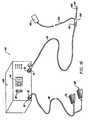
- FIG. 1is a perspective view of an electrosurgical system incorporating a power supply and an electrosurgical probe for tissue ablation, resection, incision, contraction and for vessel hemostasis according to the present invention
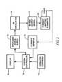
- FIG. 2schematically illustrates one embodiment of a power supply according to the present invention
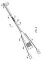
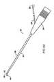
- FIG. 3is a side view of an electrosurgical probe according to the present invention.
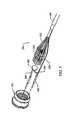
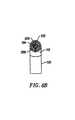
- FIG. 4is a view of the distal end portion of the probe of FIG. 3;
- FIG. 5is an exploded view of a proximal portion of the electrosurgical probe
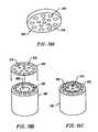
- FIGS. 6A and 6Bare perspective and end views, respectively, of an alternative electrosurgical probe incorporating an inner fluid lumen
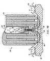
- FIGS. 7A-7Care cross-sectional views of the distal portions of three different embodiments of an electrosurgical probe, according to the present invention.
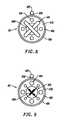
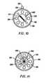
- FIGS. 8-11are end views of alternative embodiments of the probe of FIG. 3, incorporating aspiration electrode(s);
- FIGS. 13A-13Cillustrate an alternative embodiment incorporating a screen electrode
- FIGS. 14A-14Dillustrate four embodiments of electrosurgical probes specifically designed for treating spinal defects
- FIG. 16illustrates a catheter system for electrosurgical treatment of intervertebral discs according to the present invention
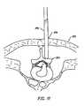
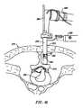
- FIGS. 17-21illustrate a method of performing a microendoscopic discectomy according to the principles of the present invention
- FIGS. 22-24illustrate another method of treating a spinal disc with one of the catheters or probes of the present invention
- FIG. 25is a perspective view of two adjacent thoracic vertebrae
- FIG. 26is a partial cross section of the spinal column which illustrates the general position of some of the interspinous tissue which connects the adjacent vertebrae;
- FIG. 27illustrates positioning an electrosurgical probe adjacent the processes of the vertebrae
- FIG. 28illustrates heating and shrinking interspinous tissue surrounding the vertebrae
- FIG. 29illustrates the vertebral column after the electrosurgical probe has been removed from the surgical site and the adjacent vertebrae are in a closer configuration
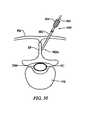
- FIG. 30schematically represents a vertebra, as seen in cross-section, in relation to an electrosurgical probe, according to one embodiment of the invention.
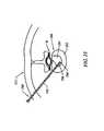
- FIG. 31schematically represents a portion of the vertebral column, as seen in left lateral view, wherein an electrosurgical probe is introduced within interspinous tissue;
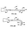
- FIG. 32Ashows a steerable electrosurgical probe wherein the shaft of the probe assumes a substantially linear configuration
- FIG. 32Bshows the steerable electrosurgical probe of FIG. 33A, wherein the shaft distal end of the probe adopts a bent configuration
- FIG. 33Ashows the shaft distal end of an electrosurgical probe positioned within an introducer extension tube and within an introducer needle
- FIG. 34schematically represents a series of steps involved in a method of treating spinal tissue with an electrosurgical probe according to the present invention
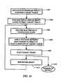
- FIG. 35schematically represents a series of steps involved in a method of treating a target tissue of the vertebral column, according to another embodiment of the invention.
- FIG. 36schematically represents a series of steps involved in a method of treating interspinous tissue, according to another embodiment of the invention.
- the present inventionprovides systems and methods for selectively applying electrical energy to a target location within or on a patient's body, particularly including support tissue or other body structures in the spine.
- These proceduresinclude treating interspinous tissue, degenerative discs, laminectomy/discectomy procedures for treating herniated discs, decompressive laminectomy for stenosis in the lumbosacral and cervical spine, localized tears or fissures in the annulus fibrosus, nucleotomy, disc fusion procedures, medial facetectomy, posterior lumbosacral and cervical spine fusions, treatment of scoliosis associated with vertebral disease, foraminotomies to remove the roof of the intervertebral foramina to relieve nerve root compression and anterior cervical and lumbar discectomies.
- These proceduresmay be performed through open procedures, or using minimally invasive techniques, such as thoracoscopy, arthroscopy, laparascopy or the like.
- the present inventioninvolves a system and method for treating the interspinous tissue (e.g., ligaments, tendons, cartilage, synovial tissue between the vertebrae, and other support tissue within and surrounding the vertebral column).
- the interspinous tissuee.g., ligaments, tendons, cartilage, synovial tissue between the vertebrae, and other support tissue within and surrounding the vertebral column.
- RF energyis used to heat and shrink the interspinous tissue to stabilize the vertebral column and reduce pain in the back and neck.
- an active electrodeis positioned adjacent the interspinous tissue and the interspinous tissue is heated, preferably with RF energy, to a sufficient temperature to shrink the interspinous tissue.
- a high frequency voltage differenceis applied between one or more active electrode(s) and one or more return electrode(s) to develop high electric field intensities in the vicinity of the target tissue to controllably heat the target tissue.
- the present inventionalso involves techniques for treating disc defects or disorders with RF energy.
- RF energyis used to ablate, debulk and/or stiffen the tissue structure of the disc to reduce the volume of the disc, thereby relieving neck and back pain.
- spinal disc tissueis volumetrically removed or ablated to form holes, channels, divots or other spaces within the disc.
- a high frequency voltageis applied between one or more active electrode(s) and one or more return electrode(s) to develop high electric field intensities in the vicinity of the target tissue.
- the high electric field intensities adjacent the active electrode(s)lead to electric field induced molecular breakdown of target tissue through molecular dissociation (rather than thermal evaporation or carbonization).
- tissue structureis volumetrically removed through molecular disintegration of larger organic molecules into smaller molecules and/or atoms, such as hydrogen, oxygen, oxides of carbon, hydrocarbons and nitrogen compounds.
- This molecular disintegrationcompletely removes the tissue structure, as opposed to prior art electrosurgical desiccation and vaporization of tissue which typically involve dehydrating the tissue by the removal of water from within the cells and extracellular fluids.
- the high electric field intensitiesmay be generated by applying a high frequency voltage that is sufficient to vaporize an electrically conductive fluid over at least a portion of the active electrode(s) in the region between the distal tip of the active electrode(s) and the target tissue.
- the electrically conductive fluidmay be a liquid or gas, such as isotonic saline, blood, or extracellular fluid, delivered to, or already present at, the target site; or a viscous fluid, such as a gel, applied to the target site. Since the vapor layer or vaporized region has a relatively high electrical impedance, it minimizes current flow into the electrically conductive fluid.
- Coblation®This ionization, under the conditions described herein, induces the discharge of energetic electrons and photons from the vapor layer and to the surface of the target tissue.
- Coblation®A more detailed description of this phenomena, termed Coblation® can be found in commonly assigned U.S. Pat. No. 5,697,882 the complete disclosure of which is incorporated herein by reference.
- the principal mechanism of tissue removal in the Coblation® mechanism of the present inventionis molecular dissociation of tissue components induced by energetic electrons or ions that have been energized in a plasma adjacent to the active electrode(s).
- a liquidis heated enough that atoms vaporize from the surface faster than they recondense, a gas is formed.
- an ionized gas or plasmais formed (the so-called “fourth state of matter”).
- the electron mean free pathincreases to enable subsequently injected electrons to cause impact ionization within these regions of low density (i.e., vapor layers or bubbles).
- the ionic particles in the plasma layerhave sufficient energy, they accelerate towards the target tissue.
- Energy evolved by the energetic electronse.g., 3.5 eV to 5 eV
- Plasmasmay be formed by heating a gas and ionizing the gas by driving an electric current through it, or by transmitting radio waves into the gas.
- these methods of plasma formationgive energy to free electrons in the plasma directly, and then electron-atom collisions liberate more electrons, and the process cascades until the desired degree of ionization is achieved.
- the electronscarry the electrical current or absorb the radio waves and, therefore, are hotter than the ions.
- the electronswhich are carried away from the tissue towards the return electrode, carry most of the plasma's heat with them, allowing the ions to break apart the tissue molecules in a substantially non-thermal manner.
- the present inventionapplies high frequency (RF) electrical energy in an electrically conductive media environment to shrink (e.g., to decrease the dimensions, tighten, contract, or reduce the volume), or remove (e.g., resect, cut, or ablate) a tissue structure, and to seal transected vessels within the region of the target tissue.
- RFhigh frequency
- the present inventionmay also be useful for sealing larger arterial vessels, e.g., on the order of about 1 mm in diameter.
- a high frequency power supplyhaving an ablation mode, wherein a first voltage is applied to an active electrode sufficient to effect molecular dissociation or disintegration of the tissue, and a coagulation mode, wherein a second, lower voltage is applied to an active electrode (either the same or a different electrode) sufficient to heat, shrink, and/or achieve hemostasis of severed vessels within the tissue.
- an electrosurgical instrumentis provided having one or more coagulation electrode(s) configured for sealing a severed vessel, such as an arterial vessel; and one or more active electrodes configured for either contracting the collagen fibers within the tissue, or removing (ablating) the tissue, e.g., by applying sufficient energy to the tissue to effect molecular dissociation.
- the coagulation electrode(s)may be configured such that a single voltage can be applied to coagulate with the coagulation electrode(s), and to ablate or shrink with the active electrode(s).
- the power supplyis combined with the coagulation instrument such that the coagulation electrode is used when the power supply is in the coagulation mode (low voltage), and the active electrode(s) are used when the power supply is in the ablation mode (higher voltage).
- one or more active electrodesare brought into close proximity to tissue at a target site, and the power supply is activated in the ablation mode such that sufficient voltage is applied between the active electrodes and the return electrode to volumetrically remove the tissue through molecular dissociation, as described below.
- the power supplyis activated in the ablation mode such that sufficient voltage is applied between the active electrodes and the return electrode to volumetrically remove the tissue through molecular dissociation, as described below.
- vessels within the tissuewill be severed. Smaller vessels will be automatically sealed with the system and method of the present invention. Larger vessels, and those with a higher flow rate, such as arterial vessels, may not be automatically sealed in the ablation mode. In these cases, the severed vessels may be sealed by activating a control (e.g., a foot pedal) to reduce the voltage of the power supply into the coagulation mode.
- a controle.g., a foot pedal
- the active electrodesmay be pressed against the severed vessel to provide sealing and/or coagulation of the vessel.
- a coagulation electrode located on the same or a different instrumentmay be pressed against the severed vessel.
- the present inventionmay be used to shrink or contract collagen connective tissue which support the vertebral column, or tissue within the disc.
- the RF energyheats the tissue directly by virtue of the electrical current flow therethrough, and/or indirectly through the exposure of the tissue to fluid heated by RF energy, to elevate the tissue temperature from normal body temperatures (e.g., 37° C.) to temperatures in the range of 45° C. to 90° C., preferably in the range from about 60° C. to 70° C.
- Thermal shrinkage of collagen fibersoccurs within a small temperature range, which, for mammalian collagen, is in the range from 60° C. to 70° C.
- the preferred depth of heating to effect the shrinkage of collagen in the heated regioni.e., the depth to which the tissue is elevated to temperatures between 60° C. to 70° C.
- the depth of heatingis usually in the range from 1.0 mm to 5.0 mm.
- the tissueis purposely damaged in a thermal heating mode to create necrosed or scarred tissue at the tissue surface.
- the high frequency voltage in the thermal heating modeis below the threshold of ablation as described above, but sufficient to cause some thermal damage to the tissue immediately surrounding the electrodes without vaporizing or otherwise debulking this tissue in situ.
- tissue temperaturein the range of about 60° C. to 100° C. to a depth of about 0.2 mm to 5 mm, usually about 1 mm to 2 mm.
- the voltage required for this thermal damagewill partly depend on the electrode configurations, the conductivity of the area immediately surrounding the electrodes, the time period in which the voltage is applied and the depth of tissue damage desired.
- the voltage level for thermal heatingwill usually be in the range of about 20 volts RMS to 300 volts RMS, preferably about 60 volts RMS to 200 volts RMS.
- the peak-to-peak voltages for thermal heating with a square wave form having a crest factor of about 2are typically in the range of about 40 volts peak-to-peak to 600 volts peak-to-peak, preferably about 120 volts peak-to-peak to 400 volts peak-to-peak.
- capacitors or other electrical elementsmay be used to increase the crest factor up to 10. The higher the voltage is within this range, the less time required. If the voltage is too high, however, the surface tissue may be vaporized, debulked or ablated, which is generally undesirable.
- the present inventionmay be used for treating degenerative discs which have one or more fissures or tears.
- the active and return electrode(s)are positioned in or around the inner wall of the annulus fibrosus such that the active electrode is adjacent to the fissure to be treated.
- High frequency voltageis applied between the active and return electrodes to heat the fissure and shrink the collagen fibers and create a seal or weld within the inner wall, thereby helping to close the fissure in the annulus.
- the return electrodewill typically be positioned proximally from the active electrode(s) on the instrument shaft, and an electrically conductive fluid will be applied to the target site to create the necessary current path between the active and return electrodes.
- the disc tissuemay complete this electrically conductive path.
- the present inventionis also useful for removing or ablating tissue around nerves, such as spinal, peripheral or cranial nerves.
- nervessuch as spinal, peripheral or cranial nerves.
- One of the significant drawbacks with prior art shavers or microdebriders, conventional electrosurgical devices, and lasersis that they do not differentiate between the target tissue and the surrounding nerves or bone. Therefore, the surgeon must be extremely careful during procedures using these devices to avoid damage to the bone or nerves within and around the target site.
- the Coblation® process for treating tissueresults in no, or minimal, collateral tissue damage, as discussed above. This allows the surgeon to remove tissue close to a nerve without causing collateral damage to the nerve.
- Peripheral nervesusually comprise a connective tissue sheath, or epineurium, enclosing the bundles of nerve fibers, each bundle being surrounded by its own sheath of connective tissue (the perineurium) to protect these nerve fibers.
- the outer protective tissue sheath or epineuriumtypically comprises a fatty tissue (e.g., adipose tissue) having substantially different electrical properties from those of the target tissue, such as intervertebral disc tissue and interspinous tissue.
- a fatty tissuee.g., adipose tissue
- the system of the present inventionmeasures the electrical properties of the tissue at the tip of the probe with one or more active electrode(s). These electrical properties may include electrical conductivity at one, several, or a range of frequencies (e.g., in the range from 1 kHz to 100 MHz), dielectric constant, capacitance or combinations of these.
- an audible signalmay be produced when the sensing electrode(s) at the tip of the probe detects the fatty tissue surrounding a nerve, or direct feedback control can be provided to only supply power to the active electrode(s) either individually or to the complete array of electrodes, if and when the tissue encountered at the tip or working end of the probe is “normal” (e.g., non-fatty) tissue based on the measured electrical properties.
- the current limiting elementsare configured such that the active electrodes will shut down or turn off when the electrical impedance reaches a threshold level.
- a threshold levelis set to the impedance of the fatty tissue surrounding nerves, the active electrodes will shut off whenever they come in contact with, or in close proximity to, nerves. Meanwhile, the other active electrodes, which are in contact with or in close proximity to target tissue, will continue to conduct electric current to the return electrode.
- This selective ablation of lower impedance tissue in combination with the Coblation® mechanism of the present inventionallows the surgeon to precisely remove tissue around nerves or bone. Applicant has found that the present invention is capable of volumetrically removing tissue closely adjacent to nerves without impairing the function of the nerves, and without significantly damaging the tissue of the epineurium.
- the Coblation® mechanism of the present inventioncan be manipulated to ablate or remove certain tissue structures, while having little effect on other tissue structures.
- the present inventionuses a technique of vaporizing electrically conductive fluid to form a plasma layer or pocket around the active electrode(s), and then inducing the discharge of energy from this plasma or vapor layer to break the molecular bonds of the tissue structure.
- Energy evolved by the energetic electronse.g., 4 eV to 5 eV
- the energy evolved by the energetic electronsmay be varied by adjusting a variety of factors, such as: the number of active electrodes; electrode size and spacing; electrode surface area; asperities and sharp edges on the electrode surfaces; electrode materials; applied voltage and power; current limiting means, such as inductors; electrical conductivity of the fluid in contact with the electrodes; density of the fluid; and other factors.
- the present inventioncan be configured to break the molecular bonds of certain tissue, while having too low an energy to break the molecular bonds of other tissue.
- fatty tissuee.g., adipose tissue
- the present invention in its current configurationgenerally does not ablate or remove such fatty tissue.
- the present inventionmay be used to effectively ablate cells to release the inner fat content in a liquid form.
- the present inventionprovides systems, apparatus and methods for selectively removing tumors, e.g., facial tumors, or other undesirable body structures while minimizing the spread of viable cells from the tumor.
- Conventional techniques for removing such tumorsgenerally result in the production of smoke in the surgical setting, termed an electrosurgical or laser plume, which can spread intact, viable bacteria or viral particles from the tumor or lesion to the surgical team or to other portions of the patient's body.
- This potential spread of viable cells or particleshas resulted in increased concerns over the proliferation of certain debilitating and fatal diseases, such as hepatitis, herpes, HIV and papillomavirus.
- high frequency voltageis applied between the active electrode(s) and one or more return electrode(s) to volumetrically remove at least a portion of the tissue of the tumor or lesion by the dissociation or disintegration of large organic molecules (e.g., proteins and nucleic acids) into non-viable atoms and low molecular species.
- the present inventionconverts solid tissue into non-condensable gases that are no longer intact or viable, and thus, incapable of spreading viable tumor cells or infectious agents to other portions of the patient's body or to the surgical staff.
- the high frequency voltageis preferably selected to effect controlled removal of such target tissue while minimizing tissue damage to surrounding or underlying tissue.
- the electrosurgical probe or catheter of the present inventioncan comprise a shaft or a handpiece having a proximal end and a distal end which supports one or more active electrode(s).
- the shaft or handpiecemay assume a wide variety of configurations, with the primary purpose being to mechanically support the active electrode and permit the treating physician to manipulate the electrode from a proximal end of the shaft.
- the shaftmay be rigid or flexible, with flexible shafts optionally being combined with a generally rigid external tube for mechanical support. Flexible shafts may be combined with pull wires, shape memory actuators, and other known mechanisms for effecting selective deflection of the distal end of the shaft to facilitate positioning of the electrode array.
- the shaftwill usually include a plurality of wires or other conductive elements running axially therethrough to permit connection of the electrode array to a connector at the proximal end of the shaft.
- the shaftwill have a suitable diameter and length to allow the surgeon to reach the target site (e.g., a disc or vertebra).
- the shaftwill usually have a length in the range of about 5.0 cm to 30.0 cm, and a diameter in the range of about 0.2 mm to about 20 mm.
- the shaftis delivered directly through the patient's back in a posterior approach.
- the shaftmay also be introduced through rigid or flexible endoscopes.
- the shaftmay be a flexible catheter that is introduced through a percutaneous penetration in the patient.
- the probemay comprise a long, thin needle (e.g., on the order of about 1 mm in diameter or less) that can be percutaneously introduced through the patient's back directly into, or adjacent to, the spine.
- the needlewill include one or more active electrode(s) for applying electrical energy to tissues within or surrounding the spine.
- the needlemay include one or more return electrode(s), or the return electrode may be positioned on the patient as a dispersive pad. In either embodiment, sufficient electrical energy is applied to the active electrode(s) to either shrink the collagen fibers within the spinal disc, to volumetrically remove tissue within the disc, or to shrink interspinous tissue (e.g., ligaments) surrounding and supporting the vertebrae.
- tissuee.g., ligaments
- the electrosurgical instrumentmay also be a catheter that is delivered percutaneously and/or endoluminally into the patient by insertion through a conventional or specialized guide catheter, or the invention may include a catheter having an active electrode or electrode array integral with its distal end.
- the catheter shaftmay be rigid or flexible, with flexible shafts optionally being combined with a generally rigid external tube for mechanical support. Flexible shafts may be combined with pull wires, shape memory actuators, and other known mechanisms for effecting selective deflection of the distal end of the shaft to facilitate positioning of the electrode or electrode array.
- the catheter shaftwill usually include a plurality of wires or other conductive elements running axially therethrough to permit connection of the electrode or electrode array and the return electrode to a connector at the proximal end of the catheter shaft.
- the catheter shaftmay include a guide wire for guiding the catheter to the target site, or the catheter may comprise a steerable guide catheter.
- the cathetermay also include a substantially rigid distal end portion to increase the torque control of the distal end portion as the catheter is advanced further into the patient's body.
- the active electrode(s)are preferably supported within or by an insulating support positioned near the distal end of the instrument shaft.
- the return electrodemay be located on the instrument shaft, on another instrument, or on the external surface of the patient (i.e., a dispersive pad).
- a dispersive padlocated on the instrument shaft, on another instrument, or on the external surface of the patient (i.e., a dispersive pad).
- the return electrodeis preferably either integrated with the instrument body, or with another device located in close proximity to the instrument body.
- the proximal end of the instrument(s)will include the appropriate electrical connections for coupling the return electrode(s) and the active electrode(s) to a high frequency power supply, such as an electrosurgical generator.
- the active electrode(s)have an active portion or surface with surface geometries shaped to promote high electric field intensity and associated current density along the leading edges of the electrodes. Suitable surface geometries may be obtained by creating electrode shapes that include preferential sharp edges, or by creating asperities or other surface roughness on the surface(s) of the active electrode(s). Electrode shapes according to the present invention can include the use of formed wire (e.g., by drawing round wire through a shaping die) to form electrodes with a variety of cross-sectional shapes, such as square, rectangular, L or V shaped, or the like. Electrode edges may also be created by removing a portion of the elongate metal electrode to reshape the cross-section.
- materialcan be ground along the length of a round or hollow wire electrode to form D or C shaped wires, respectively, with edges facing in the cutting direction.
- materialcan be removed at closely spaced intervals along the electrode length to form transverse grooves, slots, threads or the like along the electrodes.
- the active electrode surface(s)may be modified through chemical, electrochemical or abrasive methods to create a multiplicity of surface asperities on the electrode surface. These surface asperities will promote high electric field intensities between the active electrode surface(s) and the target tissue to facilitate ablation or cutting of the tissue.
- surface asperitiesmay be created by etching the active electrodes with etchants having a pH less than 7.0, or by using a high velocity stream of abrasive particles (e.g., grit blasting) to create asperities on the surface of an elongated electrode.
- abrasive particlese.g., grit blasting
- the return electrodeis typically spaced proximally from the active electrode(s) a suitable distance to avoid electrical shorting between the active and return electrodes in the presence of electrically conductive fluid.
- the distal edge of the exposed surface of the return electrodeis spaced about 0.5 mm to 25 mm from the proximal edge of the exposed surface of the active electrode(s), preferably about 1.0 mm to 5.0 mm.
- this distancemay vary with different voltage ranges, conductive fluids, and depending on the proximity of tissue structures to active and return electrodes.
- the return electrodewill typically have an exposed length in the range of about 1 mm to 20 mm.
- the current flow path between the active electrodes and the return electrode(s)may be generated by submerging the tissue site in an electrical conducting fluid (e.g., within a viscous fluid, such as an electrically conductive gel) or by directing an electrically conductive fluid along a fluid path to the target site (i.e., a liquid, such as isotonic saline, hypotonic saline; or a gas, such as argon).
- the conductive gelmay also be delivered to the target site to achieve a slower, more controlled delivery rate of conductive fluid.
- the viscous nature of the gelmay allow the surgeon to more easily contain the gel around the target site (e.g., rather than attempting to contain isotonic saline).
- the body's natural conductive fluidssuch as blood or extracellular fluids, may be sufficient to establish a conductive path between the return electrode(s) and the active electrode(s), and to provide the conditions for establishing a vapor layer, as described above.
- conductive fluid that is introduced into the patientis generally preferred over blood because blood will tend to coagulate at certain temperatures.
- the patient's bloodmay not have sufficient electrical conductivity to adequately form a plasma in some applications.
- a liquid electrically conductive fluide.g., isotonic saline
- the system of the present inventionmay include one or more suction lumen(s) in the instrument, or on another instrument, coupled to a suitable vacuum source for aspirating fluids from the target site.
- the inventionmay include one or more aspiration electrode(s) coupled to the distal end of the suction lumen for ablating, or at least reducing the volume of, non-ablated tissue fragments that are aspirated into the lumen.
- the aspiration electrode(s)function mainly to inhibit clogging of the lumen that may otherwise occur as larger tissue fragments are drawn therein.
- the aspiration electrode(s)may be different from the ablation active electrode(s), or the same electrode(s) may serve both functions.
- suctionit may be desirable to contain the excess electrically conductive fluid, tissue fragments, and/or gaseous products of ablation at or near the target site with a containment apparatus, such as a basket, retractable sheath, or the like.
- a containment apparatussuch as a basket, retractable sheath, or the like.
- This embodimenthas the advantage of ensuring that the conductive fluid, tissue fragments, or ablation products do not flow through the patient's vasculature or into other portions of the body.
- the present inventionmay use a single active electrode or an array of active electrodes spaced around the distal surface of a catheter or probe.
- the electrode arrayusually includes a plurality of independently current-limited and/or power-controlled active electrodes to apply electrical energy selectively to the target tissue while limiting the unwanted application of electrical energy to the surrounding tissue and environment resulting from power dissipation into surrounding electrically conductive fluids, such as blood, normal saline, and the like.
- the active electrodesmay be independently current-limited by isolating the terminals from each other and connecting each terminal to a separate power source that is isolated from the other active electrodes.
- the active electrodesmay be connected to each other at either the proximal or distal ends of the catheter to form a single wire that couples to a power source.
- each individual active electrode in the electrode arrayis electrically insulated from all other active electrodes in the array within the instrument and is connected to a power source which is isolated from each of the other active electrodes in the array or to circuitry which limits or interrupts current flow to the active electrode when low resistivity material (e.g., blood, electrically conductive saline irrigant or electrically conductive gel) causes a lower impedance path between the return electrode and the individual active electrode.
- the isolated power sources for each individual active electrodemay be separate power supply circuits having internal impedance characteristics which limit power to the associated active electrode when a low impedance return path is encountered.
- the isolated power sourcemay be a user selectable constant current source.
- a single power sourcemay be connected to each of the active electrodes through independently actuatable switches, or by independent current limiting elements, such as inductors, capacitors, resistors and/or combinations thereof.
- the current limiting elementsmay be provided in the instrument, connectors, cable, controller or along the conductive path from the controller to the distal tip of the instrument.
- the resistance and/or capacitancemay occur on the surface of the active electrode(s) due to oxide layers which form on certain metals (e.g., titanium), or a resistive coating on the surface of a metal (such as platinum).
- the tip region of the instrumentmay comprise many independent active electrodes designed to deliver electrical energy in the vicinity of the tip.
- the selective application of electrical energy to the conductive fluidis achieved by connecting each individual active electrode and the return electrode to a power source having independently controlled or current limited channels.
- the return electrode(s)may comprise a single tubular member of conductive material proximal to the electrode array at the tip.
- the single tubular membermay also serve as a conduit for the supply of the electrically conductive fluid between the active and return electrodes.
- the instrumentmay comprise an array of return electrodes at the distal tip of the instrument (together with the active electrodes) to maintain the electric current at the tip.
- the application of high frequency voltage between the return electrode(s) and the electrode arrayresults in the generation of high electric field intensities at the distal tips of the active electrodes with conduction of high frequency current from each individual active electrode to the return electrode.
- the current flow from each individual active electrode to the return electrode(s)is controlled by either active or passive means, or a combination thereof, to deliver electrical energy to the surrounding conductive fluid while minimizing energy delivery to surrounding (non-target) tissue.
- the tissue volume over which energy is dissipated(i.e., over which a high current density exists) may be more precisely controlled by, for example, the use of a multiplicity of small active electrodes whose effective diameters or principal dimensions range from about 10 mm to 0.01 mm, preferably from about 2 mm to 0.05 mm, and more preferably from about 1 mm to 0.1 mm.
- the arraywill usually include at least two isolated active electrodes, often at least five active electrodes, often greater than 10 active electrodes and even 50 or more active electrodes, disposed over the distal contact surfaces on the shaft.
- the use of small diameter active electrodesincreases the electric field intensity and reduces the extent or depth of tissue heating as a consequence of the divergence of current flux lines which emanate from the exposed surface of each active electrode.
- the inventionis not limited to electrically isolated active electrodes, or even to a plurality of active electrodes.
- the array of active electrodesmay be connected to a single lead that extends through the catheter shaft to a power source of high frequency current.
- the instrumentmay incorporate a single electrode that extends directly through the catheter shaft or is connected to a single lead that extends to the power source.
- the active electrode(s)may have ball shapes (e.g., for tissue vaporization and desiccation), twizzle shapes (for vaporization and needle-like cutting), spring shapes (for rapid tissue debulking and desiccation), twisted metal shapes, annular or solid tube shapes or the like.
- the electrode(s)may comprise a plurality of filaments, rigid or flexible brush electrode(s) (for debulking a tumor, such as a fibroid, bladder tumor or a prostate adenoma), side-effect brush electrode(s) on a lateral surface of the shaft, coiled electrode(s), or the like.
- the electrode support and the fluid outletmay be recessed from an outer surface of the instrument or handpiece to confine the electrically conductive fluid to the region immediately surrounding the electrode support.
- the shaftmay be shaped so as to form a cavity around the electrode support and the fluid outlet. This helps to assure that the electrically conductive fluid will remain in contact with the active electrode(s) and the return electrode(s) to maintain the conductive path therebetween. In addition, this will help to maintain a vapor layer and subsequent plasma layer between the active electrode(s) and the tissue at the treatment site throughout the procedure, which reduces the thermal damage that might otherwise occur if the vapor layer were extinguished due to a lack of conductive fluid. Provision of the electrically conductive fluid around the target site also helps to maintain the tissue temperature at desired levels.
- the active electrodesare spaced from the target tissue a sufficient distance to minimize or avoid contact between the tissue and the vapor layer formed around the active electrodes.
- contact between the heated electrons in the vapor layer and the tissueis minimized as these electrons travel from the vapor layer back through the conductive fluid to the return electrode.
- the ions within the plasmawill have sufficient energy, under certain conditions such as higher voltage levels, to accelerate beyond the vapor layer to the tissue.
- the bonds of tissue componentsare dissociated or broken as in previous embodiments, while minimizing the electron flow, and thus the thermal energy, in contact with the tissue.
- the electrically conductive fluidshould have a minimum threshold conductivity to provide a suitable conductive path between the return electrode and the active electrode(s).
- the electrical conductivity of the fluid(in units of milliSiemens per centimeter or mS/cm) will usually be greater than 0.2 mS/cm, preferably greater than 2 mS/cm, and more preferably greater than 10 mS/cm.
- the electrically conductive fluidis isotonic saline, which has an electrical conductivity of about 17 mS/cm. Applicant has found that a more conductive fluid, or one with a higher ionic concentration, will usually provide a more aggressive ablation rate.
- a saline solution with higher levels of sodium chloride than isotonic saline(which is on the order of about 0.9% sodium chloride), e.g., on the order of greater than 1% or between about 3% and 20%, may be desirable.
- the inventionmay be used with different types of conductive fluids that increase the power of the plasma layer by, for example, increasing the quantity of ions in the plasma, or by providing ions that have higher energy levels than sodium ions.
- the present inventionmay be used with elements other than sodium, such as potassium, magnesium, calcium and other metals in Groups located towards the left side of the Periodic Table.
- other electronegative elementsmay be used in place of chlorine, such as fluorine.
- the voltage difference applied between the return electrode(s) and the active electrode(s)will be at high or radio frequency, typically between about 5 kHz and 20 MHz, usually being between about 30 kHz and 2.5 MHz, preferably being between about 50 kHz and 500 kHz, often less than 350 kHz, and often between about 100 kHz and 200 kHz.
- a frequency of about 100 kHzis useful because the tissue impedance is much greater at this frequency.
- higher frequenciesmay be desirable (e.g., 400-600 kHz) to minimize low frequency current flow into the heart or the nerves of the head and neck.
- the RMS (root mean square) voltage appliedwill usually be in the range from about 5 volts to 1000 volts, preferably being in the range from about 10 volts to 500 volts, often between about 150 to 400 volts depending on the active electrode size, the operating frequency and the operation mode of the particular procedure or desired effect on the tissue (i.e., contraction, coagulation, cutting, or ablation).
- the peak-to-peak voltage for ablation or cutting, with a square wave formwill be in the range of 10 volts to 2000 volts, and preferably in the range of 100 volts to 1800 volts, and more preferably in the range of about 300 volts to 1500 volts, often in the range of about 300 volts to 800 volts peak to peak (again, depending on the electrode size, number of electrodes, the operating frequency, and the operation mode).
- Lower peak-to-peak voltageswill be used for tissue coagulation, thermal heating of tissue, or collagen contraction, and will typically be in the range from 50 to 1500, preferably 100 to 1000 and more preferably 120 to 400 volts peak-to-peak (again, these values are computed using a square wave form).
- the voltageis usually delivered in a series of voltage pulses or alternating current of time varying voltage amplitude, with a sufficiently high frequency (e.g., on the order of 5 kHz to 20 MHz) such that the voltage is effectively applied continuously (as compared with e.g., lasers claiming small depths of necrosis, which are generally pulsed about 10 Hz to 20 Hz).
- the duty cyclei.e., cumulative time in any one-second interval that energy is applied
- the preferred power source of the present inventiondelivers a high frequency current selectable to generate average power levels ranging from several milliwatts to tens of watts per electrode, depending on the volume of target tissue being treated, and/or the maximum allowed temperature selected for the instrument tip.
- the power sourceallows the user to select the voltage level according to the specific requirements of a particular neurosurgery procedure, cardiac surgery, arthroscopic surgery, dermatological procedure, ophthalmic procedures, open surgery, or other endoscopic surgery procedure.
- the power sourcemay have an additional filter, for filtering leakage voltages at frequencies below 100 kHz, particularly voltages around 60 kHz.
- the power sourcemay be current limited or otherwise controlled so that undesired heating of the target tissue or surrounding (non-target) tissue does not occur.
- current limiting inductorsare placed in series with each independent active electrode, where the inductance of the inductor is in the range of 10 uH to 50,000 uH, depending on the electrical properties of the target tissue, the desired tissue heating rate and the operating frequency.
- capacitor-inductor (LC) circuit structuresmay be employed, as described previously in U.S. Pat. No. 5,697,909, the complete disclosure of which is incorporated herein by reference. Additionally, current limiting resistors may be selected.
- Electrosurgical system 11generally comprises an electrosurgical handpiece or probe 10 connected to a power supply 28 for providing high frequency voltage to a target site, and a fluid source 21 for supplying electrically conductive fluid 50 to probe 10 .
- electrosurgical system 11may include an endoscope (not shown) with a fiber optic head light for viewing the surgical site.
- the endoscopemay be integral with probe 10 , or it may be part of a separate instrument.
- the system 11may also include a vacuum source (not shown) for coupling to a suction lumen or tube 205 (see FIG. 2) in probe 10 for aspirating the target site.
- probe 10generally includes a proximal handle 19 and an elongate shaft 18 having an array 12 of active electrodes 58 at its distal end.
- a connecting cable 34has a connector 26 for electrically coupling active electrodes 58 to power supply 28 .
- the active electrodes 58are electrically isolated from each other and each of terminal of active electrodes 58 is connected to an active or passive control network within power supply 28 by means of a plurality of individually insulated conductors (not shown).
- a fluid supply tube 15is connected to a fluid tube 14 of probe 10 for supplying electrically conductive fluid 50 to the target site. Fluid supply tube 15 may be connected to a suitable pump (not shown), if desired.
- Power supply 28has an operator controllable voltage level adjustment 30 to change the applied voltage level, which is observable at a voltage level display 32 .
- Power supply 28also includes first, second and third foot pedals 37 , 38 , 39 and a cable 36 which is removably coupled to power supply 28 .
- the foot pedals 37 , 38 , 39allow the surgeon to remotely adjust the energy level applied to active electrodes 58 .
- first foot pedal 37is used to place the power supply into the “ablation” mode and second foot pedal 38 places power supply 28 into the “sub-ablation” mode (e.g., for coagulation or contraction of tissue).
- the third foot pedal 39allows the user to adjust the voltage level within the “ablation” mode.
- a sufficient voltageis applied to the active electrodes to establish the requisite conditions for molecular dissociation of the tissue (i.e., vaporizing a portion of the electrically conductive fluid, forming charged particles within the vapor layer, and accelerating these charged particles).
- the requisite voltage level for ablationwill vary depending on the number, size, shape and spacing of the electrodes, the distance to which the electrodes extend from the support member, etc.
- the power supply 28applies a low enough voltage to the active electrodes to avoid vaporization of the electrically conductive fluid and subsequent molecular dissociation of the tissue.
- the surgeonmay automatically toggle the power supply between the ablation and sub-ablation modes by alternately stepping on foot pedals 37 , 38 , respectively. In some embodiments, this allows the surgeon to quickly move between coagulation/thermal heating and ablation in situ, without having to remove his/her concentration from the surgical field or without having to request an assistant to switch the power supply.
- the probetypically will simultaneously seal and/or coagulate small severed vessels within the tissue.
- the surgeoncan simply step on foot pedal 38 , automatically lowering the voltage level below the threshold level for ablation, and apply sufficient pressure onto the severed vessel for a sufficient period of time to seal and/or coagulate the vessel. After this is completed, the surgeon may quickly move back into the ablation mode by stepping on foot pedal 37 .
- the high frequency power supply of the present inventionis configured to apply a high frequency voltage of about 10 volts RMS to 500 volts RMS between one or more active electrodes (and/or a coagulation electrode) and one or more return electrodes.
- the power supplyapplies about 70 volts RMS to 350 volts RMS in the ablation mode, and about 20 volts to 90 volts in a subablation mode, preferably 45 volts to 70 volts in the subablation mode (these values will, of course, vary depending on the probe configuration attached to the power supply and the desired mode of operation).
- the preferred power source of the present inventiondelivers a high frequency current selectable to generate average power levels ranging from several milliwatts to tens of watts per electrode, depending on the volume of target tissue being treated, and/or the maximum allowed temperature selected for the probe tip.
- the power sourceallows the user to select the voltage level according to the specific requirements of a particular procedure, e.g., spinal surgery, arthroscopic surgery, dermatological procedure, ophthalmic procedures, open surgery, or other endoscopic surgery procedure.
- the power supply or generatorgenerally comprises a radio frequency (RF) power oscillator 70 having output connections for coupling via a power output signal 71 to the load impedance, which is represented by the electrode assembly when the electrosurgical probe is in use.
- RF oscillator 70operates at about 100 kHz.
- the RF oscillator 70is not limited to this frequency and may operate at frequencies of about 300 kHz to 600 kHz. In particular, for cardiac applications, the RF oscillator will preferably operate in the range of about 400 kHz to about 600 kHz.
- the RF oscillatorwill generally supply a square wave signal with a crest factor of about 1 to 2.
- this signalmay be a sine wave signal or other suitable wave signal depending on the application and other factors, such as the voltage applied, the number and geometry of the electrodes, etc.
- the power output signal 71is designed to incur minimal voltage decrease (i.e., sag) under load. This improves the applied voltage to the active electrodes and the return electrode, which improves the rate of volumetric removal of tissue during a procedure involving ablation.
- Switching power supply 72allows the generator to achieve high peak power output without the large size and weight of a bulky transformer.
- the architecture of switching power supply 72has also been designed to reduce electromagnetic noise such that U.S. and foreign EMI requirements are met. This architecture comprises a zero voltage switching or crossing, which causes the transistors to turn ON and OFF when the voltage is zero. Therefore, the electromagnetic noise produced by the transistors switching is vastly reduced.
- the switching power supply 72operates at about 100 kHz.
- the power supplygenerally comprises a main or mother board containing generic electrical components required for many different surgical procedures (e.g., arthroscopy, urology, general surgery, dermatology, neurosurgery, etc.), and a daughter board containing application specific current-limiting circuitry (e.g., inductors, resistors, capacitors, and the like).
- the daughter boardis coupled to the mother board by a detachable multi-pin connector to allow convenient conversion of the power supply to, e.g., applications requiring a different current limiting circuit design.
- the daughter boardpreferably comprises a plurality of inductors of about 200 to 400 microhenries, usually about 300 microhenries, for each of the channels supplying current to the active electrodes.
- FIGS. 3-5illustrate an exemplary electrosurgical probe 20 constructed according to the principles of the present invention.
- probe 20generally includes an elongated shaft 100 which may be flexible or rigid, a handle 204 coupled to the proximal end of shaft 100 and an electrode support member 102 coupled to the distal end of shaft 100 .
- Shaft 100preferably comprises an electrically conducting material, usually metal, such as tungsten, stainless steel alloys, platinum or its alloys, titanium or its alloys, molybdenum or its alloys, and nickel or its alloys.
- shaft 100includes an electrically insulating jacket 108 , which is typically formed as one or more electrically insulating sheaths or coatings, such as polytetrafluoroethylene, polyimide, and the like.
- the provision of the electrically insulating jacket over the shaftprevents direct electrical contact between these metal elements and any adjacent non-target body structure or the surgeon. Such direct electrical contact between a body structure and an exposed electrode could result in unwanted heating and necrosis of the non-target structure at the point of contact.
- a return electrode 112may comprise an annular band coupled to an insulating shaft and having a connector extending within the shaft to the shaft proximal end.
- Handle 204typically comprises a plastic material that is easily molded into a suitable shape for handling by the surgeon. Handle 204 defines an inner cavity (not shown) that houses the electrical connections 250 (FIG. 5 ), and provides a suitable interface for connection to an electrical connecting cable 22 (see FIG. 1 ). Electrode support member 102 extends from the distal end of shaft 100 (usually about 1 mm to 20 mm), and provides support for a plurality of electrically isolated active electrodes 104 (see FIG. 4 ). As shown in FIG. 4, a fluid tube 233 extends through an opening in handle 204 , and includes a connector 235 for connection to a fluid supply source, for supplying electrically conductive fluid to the target site.
- fluid tube 233may extend through a single lumen (not shown) in shaft 100 , or it may be coupled to a plurality of lumens (also not shown) that extend through shaft 100 to a plurality of openings at its distal end.
- fluid tube 239is a plastic tubing that extends along the exterior of shaft 100 to a point just distal of return electrode 112 (see FIG. 4 ).
- the fluidis directed through an opening 237 past return electrode 112 to the active electrodes 104 .
- Probe 20may also include a valve 17 (FIG. 1) or equivalent structure for controlling the flow rate of the electrically conductive fluid to the target site.
- Electrode support member 102has a substantially planar tissue treatment surface 212 (FIG. 4) that is usually at an angle of about 10 degrees to 90 degrees relative to the longitudinal axis of shaft 100 , preferably about 30 degrees to 60 degrees and more preferably about 45 degrees.
- the distal portion of shaft 100comprises a flexible material which can be deflected relative to the longitudinal axis of the shaft. Such deflection may be selectively induced by mechanical tension of a pull wire, for example, or by a shape memory wire that expands or contracts by externally applied temperature changes.
- U.S. Pat. No. 5,697,909the complete disclosure of which is incorporated herein by reference.
- probe 20includes a return electrode 112 for completing the current path between active electrodes 104 and a high frequency power supply 28 (see FIG. 1 ).
- return electrode 112preferably comprises an exposed portion of shaft 100 shaped as an annular conductive band near the distal end of shaft 100 slightly proximal to tissue treatment surface 212 of electrode support member 102 , typically about 0.5 mm to 10 mm and more preferably about 1 mm to 10 mm.
- Return electrode 112 or shaft 100is coupled to a connector 258 (FIG. 5) that extends to the proximal end of probe 10 , where it is suitably connected to power supply 28 (FIG. 1 ).
- Electrically conductive fluidcan be continually resupplied to maintain the conduction path between return electrode 112 and active electrodes 104 .
- the distal portion of probe 20may be dipped into a source of electrically conductive fluid, such as a gel or isotonic saline, prior to positioning the probe distal portion at the target site.
- a source of electrically conductive fluidsuch as a gel or isotonic saline
- the surface tension of the fluid and/or the viscous nature of a gelallows the conductive fluid to remain around the active and return electrodes for long enough to complete its function according to the present invention, as described below.
- the conductive fluidsuch as a gel, may be applied directly to the target site.
- the fluid pathmay be formed in probe 20 by, for example, an inner lumen or an annular gap between the return electrode and a tubular support member within shaft 100 (see FIGS. 7 A and 7 B).
- This annular gapmay be formed near the perimeter of the shaft 100 such that the electrically conductive fluid tends to flow radially inward towards the target site, or it may be formed towards the center of shaft 100 so that the fluid flows radially outward.
- a fluid sourcee.g., a bag of fluid elevated above the surgical site or having a pumping device
- a fluid supply tubenot shown
- a more complete description of an electrosurgical probe incorporating one or more fluid lumen(s)can be found in U.S. Pat. No. 5,697,281, the complete disclosure of which is incorporated herein by reference.
- the electrically isolated active electrodes 104are spaced apart over tissue treatment surface 212 of electrode support member 102 .
- the tissue treatment surface and individual active electrodes 104will usually have dimensions within the ranges set forth above.
- the tissue treatment surface 212has a circular cross-sectional shape with a diameter in the range of 1 mm to 20 mm.
- the individual active electrodes 104preferably extend from tissue treatment surface 212 by a distance of about 0.1 mm to 4 mm, usually about 0.2 mm to 2 mm. Applicant has found that this configuration increases the high electric field intensities and associated current densities around active electrodes 104 to facilitate the ablation and shrinkage of tissue as described in detail above.
- the probeincludes a single, larger opening 209 in the center of tissue treatment surface 212 , and a plurality of active electrodes (e.g., about 3-15) around the perimeter of surface 212 (see FIG. 4 ).
- the probemay include a single, annular, or partially annular, active electrode at the perimeter of the tissue treatment surface.
- the central opening 209is coupled to a suction lumen (not shown) within shaft 100 and a suction tube 211 (FIG. 3) for aspirating tissue, fluids and/or gases from the target site.
- the electrically conductive fluidgenerally flows radially inward past active electrodes 104 and then back through the opening 209 . Aspirating the electrically conductive fluid during surgery allows the surgeon to see the target site, and it prevents the fluid from flowing into the patient's body.
- the distal tip of probemay have a variety of different configurations.
- the probemay include a plurality of openings 209 around the outer perimeter of tissue treatment surface 212 (see FIG. 6 B).
- the active electrodes 104extend distally from the center of tissue treatment surface 212 such that they are located radially inward from openings 209 .
- the openingsare suitably coupled to fluid tube 233 for delivering electrically conductive fluid to the target site, and suction tube 211 for aspirating the fluid after it has completed the conductive path between the return electrode 112 and the active electrodes 104 .
- FIG. 5illustrates the electrical connections 250 within handle 204 for coupling active electrodes 104 and return electrode 112 to the power supply 28 .
- a plurality of wires 252extend through shaft 100 to couple active electrodes 104 to a plurality of pins 254 , which are plugged into a connector block 256 for coupling to a connecting cable 22 (FIG. 1 ).
- return electrode 112is coupled to connector block 256 via a wire 258 and a plug 260 .
- the probe 20further includes an identification element that is characteristic of the particular electrode assembly so that the same power supply 28 can be used for different electrosurgical operations.
- the probe 20includes a voltage reduction element or a voltage reduction circuit for reducing the voltage applied between the active electrodes 104 and the return electrode 112 .
- the voltage reduction elementserves to reduce the voltage applied by the power supply so that the voltage between the active electrodes and the return electrode is low enough to avoid excessive power dissipation into the electrically conductive medium and/or ablation of the tissue at the target site.
- the voltage reduction elementallows the power supply 28 to apply two different voltages simultaneously to two different electrodes (see FIG. 14 D).
- the voltage reduction elementprimarily allows the electrosurgical probe 20 / 90 to be compatible with other power supply units (for example, various electrosurgical power supply units manufactured by ArthroCare Corporation, Sunnyvale, Calif.) that are adapted to apply higher voltages for ablation or vaporization of tissue.
- other power supply unitsfor example, various electrosurgical power supply units manufactured by ArthroCare Corporation, Sunnyvale, Calif.
- the voltage reduction elementwill serve to reduce a voltage of about 100 volts RMS to 170 volts RMS (which is a setting of 1 or 2 on the ArthroCare Model 970 and 2000 Generators (ArthroCare Corporation, Sunnyvale, Calif.)) to about 45 volts RMS to 60 volts RMS, which is a suitable voltage for coagulation of tissue without ablation (e.g., molecular dissociation) of the tissue.
- the probewill typically not require a voltage reduction element.
- the probemay include a voltage increasing element or circuit, if desired.
- the cable 22 that couples the power supply 28 to the probe 20 / 90may be used as a voltage reduction element.
- the cablehas an inherent capacitance that can be used to reduce the power supply voltage if the cable is placed into the electrical circuit between the power supply, the active electrodes and the return electrode.
- the cable 22may be used alone, or in combination with one of the voltage reduction elements discussed above, e.g., a capacitor.
- the present inventioncan be used with a power supply that is adapted to apply a voltage within the selected range for treatment of tissue. In this embodiment, a voltage reduction element or circuitry may not be desired.
- FIGS. 7A-7Cschematically illustrate the distal portion of three different embodiments of probe 90 according to the present invention.
- active electrodes 104are anchored in electrode support 102 .
- Electrode support 102may comprise a matrix of suitable insulating material (e.g., a silicone rubber, a ceramic, or glass material, such as alumina, zirconia and the like) which could be formed at the time of manufacture in a flat, hemispherical or other shape according to the requirements of a particular procedure.
- the support matrix materialis alumina (available from Kyocera Industrial Ceramics Corporation, Elkgrove, Ill.).
- Aluminahas the advantages of high thermal conductivity, good electrically insulative properties, high flexural modulus.
- the support 102is adhesively joined to a tubular support member 78 that extends most or all of the distance between support 102 and the proximal end of probe 90 .
- Tubular member 78preferably comprises an electrically insulating material, such as an epoxy or silicone-based material.
- active electrodes 104extend through pre-formed openings in the support 102 so that they protrude above tissue treatment surface 212 by the desired distance.
- the electrodesare then bonded to the tissue treatment surface 212 of support 102 , typically by an inorganic sealing material 80 .
- Sealing material 80is selected to provide effective electrical insulation, and good adhesion to both alumina support 102 and the platinum or titanium active electrodes.
- Sealing material 80additionally should have a compatible thermal expansion coefficient and a melting point well below that of platinum or titanium and alumina or zirconia, typically being a glass or glass ceramic.
- return electrode 112comprises an annular member positioned around the exterior of shaft 100 of probe 90 .
- Return electrode 112may fully or partially circumscribe tubular support member 78 to form an annular gap 54 therebetween for flow of electrically conductive liquid 50 therethrough, as discussed below.
- Gap 54preferably has a width in the range of 0.25 mm to 4 mm.
- probemay include a plurality of longitudinal ribs between tubular support member 78 and return electrode 112 to form a plurality of fluid lumens extending along the perimeter of shaft 100 . In this embodiment, the plurality of lumens will extend to a plurality of openings.
- Return electrode 112is disposed within an electrically insulative jacket 18 , which is typically formed as one or more electrically insulative sheaths or coatings, such as polytetrafluoroethylene, polyamide, and the like.
- the provision of the electrically insulative jacket 18 over return electrode 112prevents direct electrical contact between return electrode 112 and any adjacent, non-target tissue or body structure. Such direct electrical contact between a body structure and an exposed electrode member 112 could result in unwanted heating and necrosis of the non-target structure at the point of contact.
- return electrode 112is not directly connected to active electrodes 104 .
- electrically conductive liquid 50e.g., isotonic saline
- Fluid path 83is formed by annular gap 54 between outer return electrode 112 and tubular support member 78 .
- the electrically conductive liquid 50 flowing through fluid path 83provides a pathway for electrical current flow between active electrodes 104 and return electrode 112 , as illustrated by the current flux lines 60 in FIG. 7 A.
- FIG. 7Billustrates another alternative embodiment of electrosurgical probe 90 which has a return electrode 112 positioned within tubular member 78 .
- Return electrode 112is preferably substantially cylindrical defining an inner lumen 57 for allowing electrically conductive liquid 50 (e.g., isotonic saline) to flow therethrough in electrical contact with return electrode 112 .
- electrically conductive liquid 50e.g., isotonic saline
- a voltage differenceis applied between active electrodes 104 and return electrode 112 resulting in electrical current flow through the electrically conductive liquid 50 as shown by current flux lines 60 .
- tissue 52becomes ablated or transected in zone 88 .
- FIG. 7Cillustrates another embodiment of probe 90 that is a combination of the embodiments in FIGS. 7A and 7B. As shown, this probe includes both an inner lumen 57 and an outer gap or plurality of outer lumens 54 for flow of electrically conductive fluid.
- the return electrode 112may be positioned within tubular member 78 as in FIG. 7B, outside of tubular member 78 as in FIG. 7A, or in both locations.
- the probe 20 / 90will also include one or more aspiration electrode(s) coupled to the aspiration lumen for inhibiting clogging during aspiration of tissue fragments from the surgical site.
- one or more of the active electrodes 104may comprise loop electrodes 140 that extend across distal opening 209 of the suction lumen within shaft 100 .
- two of the active electrodes 104comprise loop electrodes 140 that cross over the distal opening 209 .
- the electrodesmay have shapes other than loops, such as the coiled configurations shown in FIGS. 9 and 10.
- the electrodesmay be formed within suction lumen proximal to the distal opening 209 , as shown in FIG. 12 .
- the main function of loop electrodes 140is to ablate portions of tissue that are drawn into the suction lumen to prevent clogging of the lumen.
- loop electrodes 140are electrically isolated from the other active electrodes 104 . In other embodiments, the loop electrodes 140 and active electrodes 104 may be electrically connected to each other such that both are activated together. Loop electrodes 140 may or may not be electrically isolated from each other. Loop electrodes 140 will usually extend only about 0.05 mm to 4 mm, preferably about 0.1 mm to 1 mm, from the tissue treatment surface of electrode support member 102 .
- the aspiration electrodesmay comprise a pair of coiled electrodes 150 that extend across distal opening 209 of the suction lumen.
- the larger surface area of the coiled electrodes 150usually increases the effectiveness of the electrodes 150 in ablating or digesting tissue fragments passing through opening 209 .
- the aspiration electrodecomprises a single coiled electrode 154 passing across the distal opening 209 of suction lumen. This single electrode 154 may be sufficient to inhibit clogging of the suction lumen.
- the aspiration electrodesmay be positioned within the suction lumen proximal to the distal opening 209 .
- these electrodesare close to opening 209 so that tissue does not clog the opening 209 before it reaches electrode 154 .
- a separate return electrode 156may be provided within the suction lumen to confine the electric currents therein.
- another embodiment of the present inventionincorporates an aspiration electrode 160 within the aspiration lumen 162 of the probe.
- the electrode 160is positioned just proximal of distal opening 209 so that the tissue fragments are ablated as they enter lumen 162 .
- the aspiration electrode 160comprises a loop electrode that extends across the aspiration lumen 162 .
- the return electrode 164is located on the exterior of the probe as in the previously described embodiments.
- the return electrode(s)may be located within the aspiration lumen 162 with the aspiration electrode 160 .
- inner insulating coating 163may be exposed at portions within the lumen 162 to provide a conductive path between this exposed portion of return electrode 164 and the aspiration electrode 160 .
- the latter embodimenthas the advantage of confining the electric currents to within the aspiration lumen.
- itis usually easier to maintain a conductive fluid path between the active and return electrodes in the latter embodiment because the conductive fluid is aspirated through the aspiration lumen 162 along with the tissue fragments.
- mesh electrode 600extending across the distal portion of aspiration lumen 162 .
- mesh electrode 600includes a plurality of openings 602 to allow fluids and tissue fragments to flow through into aspiration lumen 162 .
- the size of the openings 602will vary depending on a variety of factors.
- the mesh electrodemay be coupled to the distal or proximal surfaces of support member 102 .
- Wire mesh electrode 600comprises a conductive material, such as titanium, tantalum, steel, stainless steel, tungsten, copper, or gold, and the like.
- wire mesh electrode 600comprises a different material, having a different electric potential, than the active electrode(s) 104 .
- mesh electrode 600comprises steel, and active electrode(s) comprises tungsten. Applicant has found that a slight variance in the electrochemical potential of mesh electrode 600 and active electrode(s) 104 improves the performance of the device. Of course, it will be recognized that the mesh electrode may be electrically insulated from active electrode(s) as in previous embodiments
- metal screen 610has a plurality of peripheral openings 612 for receiving active electrodes 104 , and a plurality of inner openings 614 for allowing aspiration of fluid and tissue through opening 609 of the aspiration lumen. As shown, screen 610 is press fitted over active electrodes 104 and then adhered to shaft 100 of probe 20 . Similar to the mesh electrode embodiment, metal screen 610 may comprise a variety of conductive metals, such as titanium, tantalum, steel, stainless steel, tungsten, copper, gold or the like. In the representative embodiment, metal screen 610 is coupled directly to, or integral with, active electrode(s) 104 . In this embodiment, the active electrode(s) 104 and the metal screen 610 are electrically coupled to each other.
- FIGS. 14A to 14 Dillustrate embodiments of an electrosurgical probe 350 specifically designed for the treatment of herniated or diseased spinal discs.
- probe 350comprises an electrically conductive shaft 352 , a handle 354 coupled to the proximal end of shaft 352 and an electrically insulating support member 356 at the distal end of shaft 352 .
- Probe 350further includes a shrink wrapped insulating sleeve 358 over shaft 352 , and an exposed portion of shaft 352 that functions as the return electrode 360 .
- probe 350comprises a plurality of active electrodes 362 extending from the distal end of support member 356 .
- return electrode 360is spaced a further distance from active electrodes 362 than in the embodiments described above.
- the return electrode 360is spaced a distance of about 2.0 mm to 50 mm, preferably about 5 mm to 25 mm.
- return electrode 360has a larger exposed surface area than in previous embodiments, having a length in the range of about 2.0 mm to 40 mm, preferably about 5 mm to 20 mm. Accordingly, electric current passing from active electrodes 362 to return electrode 360 will follow a current flow path 370 that is further away from shaft 352 than in the previous embodiments. In some applications, this current flow path 370 results in a deeper current penetration into the surrounding tissue with the same voltage level, and thus increased thermal heating of the tissue.
- this increased thermal heatingmay have advantages in some applications of treating disc or other spinal defects or disorders.
- a tissue temperaturein the range of about 60° C. to 100° C. to a depth of about 0.2 mm to 5 mm, usually about 1 mm to 2 mm.
- the voltage required for this thermal heatingwill partly depend on the electrode configurations, the conductivity of the tissue and the area immediately surrounding the electrodes, the time period in which the voltage is applied, and the depth of tissue heating desired. With the electrode configurations described in FIGS. 14A-14D, the voltage level for thermal heating will usually be in the range of about 20 volts RMS to 300 volts RMS, and preferably about 60 volts RMS to 200 volts RMS.
- the peak-to-peak voltages for thermal heating with a square wave form having a crest factor of about 2are typically in the range of about 40 to 600 volts peak-to-peak, preferably about 120 to 400 volts peak-to-peak. The higher the voltage is within this range, the less time required. If the voltage is too high, however, the surface tissue may be vaporized, debulked or ablated, which is undesirable in certain procedures.
- the electrosurgical system used in conjunction with probe 350may include a dispersive return electrode 450 (see FIG. 15) which allows for switching between bipolar and monopolar modes.
- the systemwill switch between an ablation mode, where the dispersive pad 450 is deactivated and voltage is applied between active and return electrodes 362 , 360 , and a subablation or thermal heating mode, where the active electrode(s) 362 are deactivated and voltage is applied between the dispersive pad 450 and the return electrode 360 .
- a lower voltageis typically applied and the return electrode 360 functions as the active electrode to provide thermal heating and/or coagulation of tissue surrounding return electrode 360 .
- FIG. 14Billustrates yet another embodiment of the present invention.
- electrosurgical probe 350comprises an electrode assembly 372 having one or more active electrode(s) 362 and a proximally spaced return electrode 360 as in previous embodiments.
- Return electrode 360is typically spaced about 0.5 mm to 25 mm, preferably 1.0 mm to 5.0 mm from the active electrode(s) 362 , and has an exposed length of about 1 mm to 20 mm.
- electrode assembly 372includes two additional electrodes 374 , 376 spaced axially on either side of return electrode 360 . Electrodes 374 , 376 are typically spaced about 0.5 mm to 25 mm, preferably about 1 mm to 5 mm from return electrode 360 .
- the additional electrodes 374 , 376are exposed portions of shaft 352 , and the return electrode 360 is electrically insulated from shaft 352 such that a voltage difference may be applied between electrodes 374 , 376 and electrode 360 .
- probe 350may be used in at least two different modes, an ablation mode and a subablation or thermal heating mode.
- ablation modevoltage is applied between active electrode(s) 362 and return electrode 360 in the presence of electrically conductive fluid, as described above.
- electrodes 374 , 376are deactivated.
- active electrode(s) 362are deactivated and a voltage difference is applied between electrodes 374 , 376 and electrode 360 such that a high frequency current 370 flows therebetween, as shown in FIG. 14 B.
- a lower voltageis typically applied, such that the applied voltage is below the threshold for plasma formation and ablation, but sufficient to cause some thermal effect on the tissue immediately surrounding the electrodes without vaporizing or otherwise debulking this tissue, so that the current 370 provides thermal heating and/or coagulation of tissue surrounding electrodes 360 , 372 , 374 .
- FIG. 14Cillustrates another embodiment of probe 350 incorporating an electrode assembly 372 having one or more active electrode(s) 362 and a proximally spaced return electrode 360 as in previous embodiments.
- Return electrode 360is typically spaced about 0.5 mm to 25 mm, preferably 1.0 mm to 5.0 mm from the active electrode(s) 362 , and has an exposed length of about 1 mm to 20 mm.
- electrode assembly 372includes a second active electrode 380 separated from return electrode 360 by an electrically insulating spacer 382 .
- handle 354includes a switch 384 for toggling probe 350 between at least two different modes, an ablation mode and a subablation or thermal heating mode.
- the ablation modevoltage is applied between active electrode(s) 362 and return electrode 360 in the presence of electrically conductive fluid, as described above.
- electrode 380is deactivated.
- active electrode(s) 362may be deactivated and a voltage difference is applied between electrode 380 and electrode 360 such that a high frequency current 370 flows therebetween.
- active electrode(s) 362may not be deactivated as the higher resistance of the smaller electrodes may automatically send the electric current to electrode 380 without having to physically decouple electrode(s) 362 from the circuit.
- a lower voltageis typically applied below the threshold for plasma formation and ablation, but sufficient to cause some thermal effect on the tissue immediately surrounding the electrodes without vaporizing or otherwise debulking this tissue so that the current 370 provides thermal heating and/or coagulation of tissue surrounding electrodes 360 , 380 .
- electrosurgical probe 350may include a plurality of helical bands formed around shaft 352 , with one or more of the helical bands having an electrode coupled to the portion of the band such that one or more electrodes are formed on shaft 352 spaced axially from each other.
- FIG. 14Dillustrates another embodiment of the invention designed for channeling through tissue and creating lesions therein to treat spinal discs and/or snoring and sleep apnea.
- probe 350is similar to the probe in FIG. 14C having a return electrode 360 and a third, coagulation electrode 380 spaced proximally from the return electrode 360 .
- active electrode 362comprises a single electrode wire extending distally from insulating support member 356 .
- the active electrode 362may have a variety of configurations to increase the current densities on its surfaces, e.g., a conical shape tapering to a distal point, a hollow cylinder, loop electrode and the like.
- support member 356 and spacer 382are constructed of an electrically insulating material, such as a ceramic, a glass, a silicone rubber, and the like.
- the proximal insulating spacer 382may alternatively comprise a more conventional organic insulating material, as this support member 382 will generally not be in the presence of a plasma that would otherwise etch or wear away an organic material.
- the probe 350 in FIG. 14Ddoes not include a switching element.
- all three electrodesare activated when the power supply is activated.
- the return electrode 360has an opposite polarity from the active and coagulation electrodes 362 , 380 such that current 370 flows from the latter electrodes to the return electrode 360 as shown.
- the electrosurgical systemincludes a voltage reduction element or a voltage reduction circuit for reducing the voltage applied between the coagulation electrode 380 and return electrode 360 .
- the voltage reduction elementallows the power supply 28 to, in effect, apply two different voltages simultaneously to two different electrodes.
- the operatormay apply a voltage sufficient to provide ablation of the tissue at the tip of the probe (i.e., tissue adjacent to the active electrode 362 ).
- the voltage applied to the coagulation electrode 380will be insufficient to ablate tissue.
- the voltage reduction elementwill serve to reduce a voltage in the range of about 100-300 volts RMS to about 45-90 volts RMS, the latter generally representing a suitable voltage range for coagulation of tissue without ablation (e.g., molecular dissociation) of the tissue.
- the voltage reduction elementcomprises a pair of capacitors forming a bridge divider (not shown) coupled to the power supply and coagulation electrode 380 .
- the capacitorusually has a capacitance of about 200 pF to 500 pF (at 500 volts), and preferably about 300 pF to 350 pF (at 500 volts).
- the capacitorsmay be located in other places within the system, such as in, or distributed along the length of, the cable, the generator, the connector, etc.
- other voltage reduction elementssuch as diodes, transistors, inductors, resistors, capacitors or combinations thereof, may be used in conjunction with the present invention.
- the probe 350may include a coded resistor (not shown) that is constructed to lower the voltage applied between the return and coagulation electrodes 360 , 380 .
- electrical circuitsmay be employed for this purpose.
- the probewill typically not require a voltage reduction element.
- the probemay include a voltage increasing element or circuit, if desired.
- the cable 22 that couples the power supply 28 to the probe 90may be used as a voltage reduction element.
- the cablehas an inherent capacitance that can be used to reduce the power supply voltage if the cable is placed into the electrical circuit between the power supply, the active electrodes and the return electrode.
- the cable 22may be used alone, or in combination with one of the voltage reduction elements discussed above, e.g., a capacitor.
- the present inventioncan be used with a power supply that is adapted to apply two different voltages within the selected range for treatment of tissue. In this embodiment, a voltage reduction element or circuitry may not be desired.
- the probe 350is manufactured by first inserting an electrode wire (active electrode 362 ) through a ceramic tube (insulating support member 356 ) such that a distal portion of the wire extends through the distal portion of the tube, and bonding the wire to the tube, typically with an appropriate epoxy.
- a stainless steel tube (return electrode 360 )is then placed over the proximal portion of the ceramic tube, and a wire (e.g., nickel wire) is bonded, typically by spot welding, to the inside surface of the stainless steel tube.
- the stainless steel tubeis coupled to the ceramic tube by epoxy, and the device is cured in an oven or other suitable heat source.
- a second ceramic tube(insulating spacer member 382 ) is then placed inside the proximal portion of the stainless steel tube, and bonded in a similar manner.
- the shaft 352is then bonded to the proximal portion of the second ceramic tube, and insulating sleeve 358 (e.g. polyimide) is wrapped around shaft 352 such that only a distal portion of the shaft is exposed (i.e., coagulation electrode 380 ).
- the nickel wire connectionwill extend through the center of shaft 352 to connect return electrode 360 to the power supply.
- the active electrode 362may form a distal portion of shaft 352 , or it may also have a connector extending through shaft 352 to the power supply.
- the physicianpositions active electrode 362 adjacent to the tissue surface to be treated (e.g., a spinal disc).
- the power supplyis activated to provide an ablation voltage between active and return electrodes 362 , 360 and a coagulation or thermal heating voltage between coagulation and return electrodes 380 , 360 .
- An electrically conductive fluidcan then be provided around active electrode 362 , and in the junction between the active and return electrodes 360 , 362 to provide a current flow path therebetween. This may be accomplished in a variety of manners, as discussed above.
- the active electrode 362is then advanced through the space left by the ablated tissue to form a channel in the disc.
- the electric current between the coagulation and return electrodeis typically insufficient to cause any damage to the surface of the tissue as these electrodes pass through the tissue surface into the channel created by active electrode 362 .
- the physicianOnce the physician has formed the channel to the appropriate depth, he or she will cease advancement of the active electrode, and will either hold the instrument in place for approximately 5 seconds to 30 seconds, or can immediately remove the distal tip of the instrument from the channel (see detailed discussion of this below). In either event, when the active electrode is no longer advancing, it will eventually stop ablating tissue.
- coagulation electrode 380Prior to entering the channel formed by the active electrode 362 , an open circuit exists between return and coagulation electrodes 360 , 380 . Once coagulation electrode 380 enters this channel, electric current will flow from coagulation electrode 380 , through the tissue surrounding the channel, to return electrode 360 . This electric current will heat the tissue immediately surrounding the channel to coagulate any severed vessels at the surface of the channel. If the physician desires, the instrument may be held within the channel for a period of time to create a lesion around the channel, as discussed in more detail below.
- FIG. 15illustrates yet another embodiment of an electrosurgical system 440 incorporating a dispersive return pad 450 attached to the electrosurgical probe 400 .
- the inventionfunctions in the bipolar mode as described above.
- the system 440may function in a monopolar mode in which a high frequency voltage difference is applied between the active electrode(s) 410 , and the dispersive return pad 450 .
- the pad 450 and the probe 400are coupled together, and are both disposable, single-use items.
- the pad 450includes an electrical connector 452 that extends into handle 404 of probe 400 for direct connection to the power supply.
- the inventionwould also be operable with a standard return pad that connects directly to the power supply.
- the power supply 460will include a switch, e.g., a foot pedal 462 , for switching between the monopolar and bipolar modes.
- the return path on the power supplyis coupled to return electrode 408 on probe 400 , as described above.
- the return path on the power supplyis coupled to connector 452 of pad 450 , active electrode(s) 410 are decoupled from the electrical circuit, and return electrode 408 functions as the active electrode.
- active electrode(s) 410are decoupled from the electrical circuit
- return electrode 408functions as the active electrode.
- the bipolar modalitymay be preferable to limit the current penetration to the tissue.
- the dispersive return pad 450is adapted for coupling to an external surface of the patient in a region substantially close to the target site.
- the dispersive return padis designed and constructed for placement in or around the patient's shoulder, upper back or upper chest region. This design limits the current path through the patient's body to the head and neck area, which minimizes the damage that may be generated by unwanted current paths in the patient's body, particularly by limiting current flow through the patient's heart.
- the return padis also designed to minimize the current densities at the pad, to thereby minimize patient skin burns in the region where the pad is attached.
- a catheter system 440 ′generally comprises an electrosurgical catheter 460 connected to a power supply 28 by an interconnecting cable 486 for providing high frequency voltage to a target tissue and an irrigant reservoir or source 600 for providing electrically conductive fluid to the target site.
- Catheter 460generally comprises an elongate, flexible shaft body 462 including a tissue removing or ablating region 464 at the distal end of body 462 .
- the proximal portion of catheter 460includes a multi-lumen fitment 614 which provides for interconnections between lumens and electrical leads within catheter 460 and conduits and cables proximal to fitment 614 .
- a catheter electrical connector 496is removably connected to a distal cable connector 494 which, in turn, is removably connectable to power supply 28 through connector 492 .
- One or more electrically conducting lead wires (not shown) within catheter 460extend between one or more active electrodes 463 and a coagulation electrode 467 at tissue ablating region 464 and one or more corresponding electrical terminals (also not shown) in catheter connector 496 via active electrode cable branch 487 .
- a return electrode 466 at tissue ablating region 464is coupled to a return electrode cable branch 489 of catheter connector 496 by lead wires (not shown).
- lead wiresnot shown
- a single cable branchmay be used for both active and return electrodes.
- Catheter body 462may include reinforcing fibers or braids (not shown) in the walls of at least the distal ablation region 464 of body 462 to provide responsive torque control for rotation of active electrodes during tissue engagement.
- This rigid portion of the catheter body 462preferably extends only about 7 mm to 10 mm while the remainder of the catheter body 462 is flexible to provide good trackability during advancement and positioning of the electrodes adjacent target tissue.
- conductive fluid 30is provided to tissue ablation region 464 of catheter 460 via a lumen (not shown in FIG. 16) within catheter 460 .
- Fluidis supplied to lumen from the source along a conductive fluid supply line 602 and a conduit 603 , which is coupled to the inner catheter lumen at multi-lumen fitment 614 .
- the source of conductive fluide.g., isotonic saline
- a control valve 604may be positioned at the interface of fluid supply line 602 and conduit 603 to allow manual control of the flow rate of electrically conductive fluid 30 .
- a metering pump or flow regulatormay be used to precisely control the flow rate of the conductive fluid.
- System 440 ′can further include an aspiration or vacuum system (not shown) to aspirate liquids and gases from the target site.
- the aspiration systemwill usually comprise a source of vacuum coupled to fitment 614 by an aspiration connector 605 .
- FIGS. 17-20 and 23each schematically represent a section through a vertebra and vertebral disc, wherein the vertebra or disc is being accessed by an electrosurgical instrument of the invention.
- a percutaneous penetration 270is made in the patients' back 272 so that the superior lamina 274 can be accessed.
- a small needle(not shown) is used initially to localize the disc space level, and a guidewire (not shown) is inserted and advanced under lateral fluoroscopy to the inferior edge of the lamina 274 .
- Sequential cannulated dilators 276are inserted over the guide wire and each other to provide a hole from the incision 220 to the lamina 274 .
- the first dilatormay be used to “palpate” the lamina 274 , assuring proper location of its tip between the spinous process and facet complex just above the inferior edge of the lamina 274 .
- a tubular retractor 278is then passed over the largest dilator down to the lamina 274 .
- the dilators 276are removed, establishing an operating corridor within the tubular retractor 278 .
- an endoscope 280is then inserted into the tubular retractor 278 and a ring clamp 282 is used to secure the endoscope 280 .
- the formation of the operating corridor within retractor 278requires the removal of soft tissue, muscle or other types of tissue that were forced into this corridor as the dilators 276 and retractor 278 were advanced down to the lamina 274 .
- this tissueis usually removed with mechanical instruments, such as pituitary rongeurs, curettes, graspers, cutters, drills, microdebriders, and the like.
- mechanical instrumentsgreatly lengthen and increase the complexity of the procedure.
- these prior art instrumentssever blood vessels within this tissue, usually causing profuse bleeding that obstructs the surgeon's view of the target site.
- an electrosurgical probe or catheter 284 as described aboveis introduced into the operating corridor within the retractor 278 to remove the soft tissue, muscle and other obstructions from this corridor so that the surgeon can easily access and visualize the lamina 274 .
- electrically conductive fluid 285can be delivered through tube 233 and opening 237 (see FIG. 2) to the tissue.
- the fluidflows past the return electrode 112 to the active electrodes 104 at the distal end of the probe shaft.
- the rate of fluid flowis controlled with valve 17 (FIG. 1) such that the zone between the tissue and electrode support 102 is constantly immersed in fluid 285 .
- the power supply 28is then turned on and adjusted such that a high frequency voltage difference is applied between active electrodes 104 and return electrode 112 .
- the electrically conductive fluidprovides the conduction path (see current flux lines) between active electrodes 104 and the return electrode 112 .
- the high frequency voltageis sufficient to convert the electrically conductive fluid (not shown) between the target tissue and active electrode(s) 104 into an ionized vapor layer or plasma (not shown).
- the applied voltage difference between active electrode(s) 104 and the target tissuei.e., the voltage gradient across the plasma layer
- charged particles in the plasmae.g., electrons
- This molecular dissociationis accompanied by the volumetric removal of tissue and the production of low molecular weight gases, such as oxygen, nitrogen, carbon dioxide, hydrogen and methane.
- the gaseswill be aspirated through opening 209 and suction tube 211 to a vacuum source.
- excess electrically conductive fluid, and other fluidse.g., blood
- the residual heat generated by the current flux linestypically less than 150° C.
- the surgeonmay switch the power supply 28 into the coagulation mode by lowering the voltage to a level below the threshold for fluid vaporization, as discussed above. This simultaneous hemostasis results in less bleeding and facilitates the surgeon's ability to perform the procedure.
- Another advantage of the present inventionis the ability to precisely ablate soft tissue without causing necrosis or thermal damage to the underlying and surrounding tissues, nerves or bone.
- the voltagecan be controlled so that the energy directed to the target site is insufficient to ablate the lamina 274 so that the surgeon can literally clean the tissue off the lamina 274 , without ablating or otherwise effecting significant damage to the lamina.
- a laminotomy and medial facetectomyis accomplished either with conventional techniques (e.g., Kerrison punch or a high speed drill) or with the electrosurgical probe 284 as discussed above.
- retractioncan be achieved with a retractor 288 , or an instrument of the present invention can be used to precisely ablate at least a portion of the disc.
- epidural veinsare cauterized either automatically or with the coagulation mode of the present invention.
- an annulotomyis necessary, it can be accomplished with a microknife or the ablation mechanism of the present invention while protecting the nerve root with the retractor 288 .
- the herniated disc 290is then removed with a pituitary rongeur in a standard fashion, or once again through ablation as described above.
- the present inventioninvolves a channeling technique in which small holes or channels are formed within the disc 290 , and thermal energy is applied to the tissue surface immediately surrounding these holes or channels to cause thermal damage to the tissue surface, thereby stiffening and debulking the surrounding tissue structure of the disc. Applicant has discovered that such stiffening of the tissue structure in the disc helps to reduce the pressure applied against the spinal nerves by the disc, thereby relieving back and neck pain.
- the electrosurgical instrument 350is introduced to the target site at the disc 290 as described above, or in another percutaneous manner (see FIGS. 22-24 below).
- the electrode assembly 351is positioned adjacent to or against the disc surface, and electrically conductive fluid is delivered to the target site, as described above.
- the conductive fluidis applied to the target site, or the distal end of probe 350 is dipped into conductive fluid, e.g., liquid or gel, prior to introducing the probe 350 into the patient.
- the power supply 28is then activated and adjusted such that a high frequency voltage difference is applied to the electrode assembly as described above.
- the surgeonmay translate or otherwise move the electrodes relative to the target disc tissue to form holes, channels, stripes, divots, craters or the like within the disc.
- the surgeonmay purposely create some thermal damage within these holes, or channels to form scar tissue that will stiffen and debulk the disc.
- the physicianaxially translates the electrode assembly 351 into the disc tissue as the tissue is volumetrically removed to form one or more holes 392 therein (see also FIG. 21 ).
- the holes 392will typically have a diameter of less than 2 mm, preferably less than 1 mm.
- the physiciantranslates the active electrode across the outer surface of the disc to form one or more channels or troughs.
- FIG. 21is a more detailed viewed of the probe 350 of FIG. 14D forming a hole 392 in a disc 290 .
- Hole 392is preferably formed with the methods described in detail above. Namely, a high frequency voltage difference is applied between active and return electrodes 362 , 360 , respectively, in the presence of an electrically conductive fluid such that an electric current 361 passes from the active electrode 362 , through the conductive fluid, to the return electrode 360 . As shown in FIG. 21, this will result in shallow or no current penetration into the disc tissue 394 .
- the fluidmay be delivered to the target site, applied directly to the target site, or the distal end of the probe may be dipped into the fluid prior to the procedure.
- the voltageis sufficient to vaporize the fluid around active electrode 362 to form a plasma with sufficient energy to effect molecular dissociation of the tissue.
- the distal end of the probe 350is then axially advanced through the tissue as the tissue is removed by the plasma in front of the probe 350 .
- the holes 392will typically have a depth D in the range of about 0.5 cm to 2.5 cm, preferably about 1.2 cm to 1.8 cm, and a diameter d of about 0.5 mm to 5 mm, preferably about 1.0 mm to 3.0 mm. The exact diameter will, of course, depend on the diameter of the electrosurgical probe used for the procedure.
- each hole 392the conductive fluid between active and return electrodes 362 , 360 will generally minimize current flow into the surrounding tissue, thereby minimizing thermal damage to the tissue. Therefore, severed blood vessels on the surface 395 of the hole 392 may not be coagulated as the electrodes 362 advance through the tissue. In addition, in some procedures, it may be desired to thermally damage the surface 395 of the hole 392 to stiffen the tissue. For these reasons, it may be desired in some procedures to increase the thermal damage caused to the tissue surrounding hole 392 . In the embodiment shown in FIG.
- the size and spacing of these electrodes 360 , 380allows for relatively deep current penetration into the tissue 394 .
- the thermal necrosiswill extend about 1.0 mm to 5.0 mm from surface 395 of hole 392 .
- the probemay include one or more temperature sensors (not shown) on probe 350 coupled to one or more temperature displays on the power supply 28 such that the physician is aware of the temperature within the hole 392 during the procedure.
- the physicianswitches the electrosurgical system from the ablation mode to the subablation or thermal heating mode after the hole 392 has been formed. This is typically accomplished by pressing a switch or foot pedal to reduce the voltage applied to a level below the threshold required for ablation for the particular electrode configuration and the conductive fluid being used in the procedure (as described above).
- the physicianwill then remove the distal end of the probe 350 from the hole 392 .
- high frequency currentflows from the active electrodes 362 through the surrounding tissue to the return electrode 360 . This current flow heats the tissue and coagulates severed blood vessels at surface 395 .
- the electrosurgical probe of the present inventioncan be used to ablate and/or contract soft tissue within the disc 290 to allow the annulus fibrosus 292 (e.g., FIG. 19) to repair itself to prevent re-occurrence of this procedure.
- tissue contractiona sufficient voltage difference is applied between the active electrodes (e.g., 104 ) and the return electrode (e.g., 112 ) to elevate the tissue temperature from normal body temperatures (e.g., 37° C.) to temperatures in the range of 45° C. to 90° C., preferably in the range from 60° C. to 70° C. This temperature elevation causes contraction of the collagen connective fibers within the disc tissue so that the nucleus pulposus withdraws into the annulus fibrosus 292 .
- an electrically conductive fluidis delivered to the target site as described above, and heated to a sufficient temperature to induce contraction or shrinkage of the collagen fibers in the target tissue.
- the electrically conductive fluidis heated to a temperature sufficient to substantially irreversibly contract the collagen fibers, which generally requires a tissue temperature in the range of about 45° C. to 90° C., usually about 60° C. to 70° C.
- the fluidis heated by applying high frequency electrical energy to the active electrode(s) in contact with the electrically conductive fluid.
- the current emanating from the active electrode(s) 104heats the fluid and generates a jet or plume of heated fluid, which is directed towards the target tissue.
- the heated fluidelevates the temperature of the collagen sufficiently to cause hydrothermal shrinkage of the collagen fibers.
- the return electrode 112draws the electric current away from the tissue site to limit the depth of penetration of the current into the tissue, thereby inhibiting molecular dissociation and breakdown of the collagen tissue and minimizing or completely avoiding damage to surrounding and underlying tissue structures beyond the target tissue site.
- the active electrode(s) 104are held away from the tissue a sufficient distance such that the RF current does not pass into the tissue at all, but rather passes through the electrically conductive fluid back to the return electrode.
- the primary mechanism for imparting energy to the tissueis the heated fluid, rather than the electric current.
- the active electrode(s) 104are brought into contact with, or close proximity to, the target tissue so that the electric current passes directly into the tissue to a selected depth.
- the return electrodedraws the electric current away from the tissue site to limit its depth of penetration into the tissue.
- the depth of current penetrationalso can be varied with the electrosurgical system of the present invention by changing the frequency of the voltage applied to the active electrode and the return electrode. This is because the electrical impedance of tissue is known to decrease with increasing frequency due to the electrical properties of cell membranes which surround electrically conductive cellular fluid.
- an operating frequency of about 100 kHz to 200 kHzis applied to the active electrode(s) to obtain shallow depths of collagen shrinkage (e.g., usually less than 1.5 mm and preferably less than 0.5 mm).
- the size (e.g., diameter or principal dimension) of the active electrodes employed for treating the tissueare selected according to the intended depth of tissue treatment. As described previously in copending patent application PCT International Application, U.S. National Phase Serial No. PCT/US94/05168, the depth of current penetration into tissue increases with increasing dimensions of an individual active electrode (assuming other factors remain constant, such as the frequency of the electric current, the return electrode configuration, etc.).
- the depth of current penetration(which refers to the depth at which the current density is sufficient to effect a change in the tissue, such as collagen shrinkage, irreversible necrosis, etc.) is on the order of the active electrode diameter for the bipolar configuration of the present invention when operating at a frequency of about 100 kHz to about 200 kHz. Accordingly, for applications requiring a smaller depth of current penetration, one or more active electrodes of smaller dimensions would be selected. Conversely, for applications requiring a greater depth of current penetration, one or more active electrodes of larger dimensions would be selected.
- FIGS. 22-24illustrate another system and method for treating swollen or herniated spinal discs according to the present invention.
- an electrosurgical probe 700comprises a long, thin needle-like shaft 702 (e.g., on the order of about 1 mm in diameter or less) that can be percutaneously introduced posteriorly through the patient's back directly into the spine.
- the shaft 702may or may not be flexible, depending on the method of access chosen by the physician.
- the probe shaft 702will include one or more active electrode(s) 704 for applying electrical energy to tissues within the spine.
- the probe 700may include one or more return electrode(s) 706 , or the return electrode may be positioned on the patient's back as a dispersive pad (not shown). As discussed below, however, a bipolar design is preferable.
- the distal portion of shaft 702is introduced posteriorly through a small percutaneous penetration in the patient's back 272 , and advanced into the target vertebral disc 290 .
- the distal end of shaft 702may taper down to a sharper point (e.g., a needle), which can then be retracted to expose active electrode(s) 704 .
- the electrodesmay be formed around the surface of the tapered distal portion of shaft 702 (not shown).
- the distal end of shaft 702is delivered through the annulus fibrosus 292 to the target nucleus pulposus 291 , which may be herniated, extruded, non-extruded, or simply swollen.
- the distal, working end of shaft 702may be advanced such that the shaft distal portion bearing active and return electrodes 704 , 706 are positioned within nucleus pulposus 291 .
- a high frequency voltageis applied between active electrode(s) 704 and return electrode(s) 706 to heat the surrounding tissue, for example to within a temperature range suitable for contraction of collagen fibers (i.e., typically about 55° C. to about 70° C.).
- this proceduremay alternatively be accomplished with a monopolar configuration.
- FIGS. 22-24provides enhanced control of the high frequency current, which reduces the risk of spinal nerve damage.
- probe 700is removed from the target site.
- the high frequency voltageis applied between active and return electrode(s) 704 , 706 while the probe is being withdrawn through annulus fibrosus 292 .
- This applied voltageis sufficient to cause contraction of the collagen fibers within the annulus fibrosus 292 , which allows the annulus fibrosus 292 to contract around the hole formed by probe 700 , thereby improving the healing of this hole.
- the probe 700seals its own passage as it is withdrawn from the disc.
- the present inventionprovides systems and methods for treating interspinous tissue within the vertebral column, and more specifically for shrinking ligaments, cartilage, and other tissue between and around adjacent vertebrae 802 , 804 and discs 806 (e.g., FIG. 25 ).
- the interspinous tissuecan be heated, typically with high frequency energy, to shrink and tighten the interspinous tissue and to bring the adjacent vertebral facets and processes closer together so as to provide greater stability to the vertebral column, thereby alleviating symptoms.
- Interspinous tissueis used herein to generally mean any tissue that supports and/or surrounds the vertebral column.
- the interspinous tissueincludes the supraspinous ligament 801 , ligamentum flavum 803 , interspinous ligament 805 , anterior longitudinal ligament 807 , posterior longitudinal ligament 808 , the articular cartilage positioned between the vertebrae 807 , articular capsule between the vertebrae (not shown), the capsule surrounding the facet joints, synovial tissue, other tissue adjacent the facets of the superior process 809 , inferior process 811 , spinous process 813 , transverse process 815 , and the like.
- the systems and methods of the present inventioncan be used in conjunction with (e.g., before or after) other spinal surgical procedures or can be performed as a separate surgical procedure.
- an electrosurgical probecan be used to heat and shrink the capsule surrounding one of the facet joints such as the posterior facet joint, thereby tightening the joint, potentially reducing pain, and providing increased stability.
- Such surgical procedurescan be performed either in a minimally invasive or open procedure.
- the same electrosurgical instrumentcan be used to perform both the disc surgical procedure and the surgical procedure on the interspinous tissue.
- separate electrosurgical instrumentscan be used to treat the interspinous tissue and the disc.
- High frequency electrical energyis preferably used to treat the interspinous tissue.
- a sufficient voltage differenceis applied between an active electrode(s) 822 and a return electrode 824 (see FIG. 28) to elevate the tissue temperature from normal body temperatures (e.g., 37° C.) to temperatures in the range of 45° C. to 90° C., preferably in the range from 60° C. to 70° C.
- This temperature elevationcauses contraction of the interspinous tissue so that the adjacent vertebrae are drawn closer together, to a more stabilized position.
- the high frequency electrical energyis delivered through a bipolar electrosurgical.
- the bipolar designhas the advantage of minimizing the current flow through non-target tissue including nearby nerves.
- a return electrodeis preferably either integrated with the instrument body, or with another instrument located in close proximity to the instrument body. It should be appreciated however, that the present invention can also use a monopolar dispersive pad, resistive heating, or the like, to heat and shrink the interspinous tissue.
- an electrically conductive fluidis delivered to the target site as described above, and heated to a sufficient temperature to induce contraction or shrinkage of the collagen fibers in the target tissue.
- the electrically conductive fluidis heated to a temperature sufficient to substantially irreversibly contract the collagen fibers, which generally requires a tissue temperature in the range of about 45° C. to 90° C., usually about 60° C. to 70° C.
- the fluidis heated by applying high frequency electrical energy to the active electrode(s) in contact with the electrically conductive fluid.
- the current emanating from the active electrode(s) 822heats the fluid and generates a jet or plume of heated fluid, which is directed towards the target tissue.
- the heated fluidelevates the temperature of the collagen sufficiently to cause hydrothermal shrinkage of the collagen fibers.
- the return electrode 824draws the electric current away from the tissue site to limit the depth of penetration of the current into the tissue, thereby inhibiting molecular dissociation and breakdown of the collagen tissue and minimizing or completely avoiding damage to surrounding and underlying tissue structures beyond the target tissue site.
- the active electrode(s) 822are held away from the tissue a sufficient distance such that the RF current does not pass into the tissue at all, but rather passes through the electrically conductive fluid back to the return electrode.
- the primary mechanism for imparting energy to the tissueis the heated fluid, rather than the electric current.
- the active electrode(s) 822are brought into contact with, or close proximity to, the target tissue so that the electric current passes directly into the tissue to a selected depth.
- the return electrodedraws the electric current away from the tissue site to limit the depth of penetration into the tissue.
- the return electrodecan be either on the same instrument as the active electrodes or on a separate instrument.
- the depth of current penetrationcan also be varied with the electrosurgical system of the present invention by changing the frequency of the voltage applied to the active electrode and the return electrode. This is because the electrical impedance of tissue is known to decrease with increasing frequency due to the electrical properties of cell membranes which surround electrically conductive cellular fluid.
- an operating frequency of about 100 kHz to 200 kHzis applied to the active electrode(s) to obtain shallow depths of collagen shrinkage (e.g., usually less than 1.5 mm and preferably less than 0.5 mm).
- FIGS. 27 to 29show an exemplary method of heating and shrinking the interspinous tissue.
- the electrosurgical instrumenttypically accesses the spinal column either endoscopically or through an open procedure.
- the same electrosurgical instrument or probe 10can be used to treat one or more defective intervertebral discs or other portions of the spinal column as well as the interspinous tissue.
- a distal portion of the electrosurgical probe 10is introduced posteriorly through a small percutaneous penetration 820 into the annulus fibrosus of the target spinal disc 806 . After the disc has been treated, the electrosurgical probe 10 is moved adjacent to a target site of the interspinous tissue. As shown in FIG.
- the active electrode(s) 822 on the distal portion of the shaft of the electrosurgical probe 10is positioned adjacent the tissue around the processes 809 , 811 and a high frequency voltage is applied between the active electrode(s) 822 and a return electrode(s) 824 to heat the interspinous tissue to a suitable temperature for shrinkage (e.g., typically between 45° C. and 90° C.).
- a suitable temperature for shrinkagee.g., typically between 45° C. and 90° C.
- the distal or working end of probe 10can be repositioned to treat other regions of the interspinous tissue (FIG. 26 ), which can be subsequently heated and shrunk. Shrinkage of the interspinous tissue can bring the facets in the inferior and superior processes 809 , 811 of the adjacent vertebrae 802 , 804 to a more stable configuration.
- an electrically conductive fluid 826can be placed or delivered to the target site and heated to a sufficient temperature to induce contraction or shrinkage of the collagen fibers in the target tissue.
- the shrunken interspinous tissuecan move the adjacent vertebrae 802 , 804 to a closer, more stabilized position.
- the electrosurgical probe 10is removed from the target site and the percutaneous opening is closed.
- the adjacent vertebrae 802 , 804will be in a closer, more stable configuration.
- FIG. 30schematically represents an electrosurgical probe 900 positioned in the vicinity of a spinous process SP of a vertebra, according to one aspect of the invention. Also shown in FIG. 30 is the body VB of the vertebra in relation to the spinal cord SC, and the dura mater DM.
- Probe 900includes a handle 904 , and a shaft 902 having shaft distal end 902 a. Probe 900 typically includes at least one active electrode and at least one return electrode located at shaft distal end 902 a (not shown in FIG. 30 ).
- Probe 900is capable of operating in at least the subablation mode to provide thermal heating to tissue in contact with, or in close proximity to, shaft distal end 902 a. Probe 900 may also be capable of operating in an ablation mode.
- probe 900may have an electrode configuration substantially the same or similar to those described above, for example, with reference to FIGS. 14B-14D.
- a cable or other connector 903couples probe 900 to a suitable power supply (e.g., power supply 28 , FIG. 1, FIG. 2) for supplying a high frequency voltage between the at least one active electrode and the at least one return electrode, essentially as described hereinabove.
- a suitable power supplye.g., power supply 28 , FIG. 1, FIG. 2
- suitable high frequency voltage between the at least one active electrode and the at least one return electrode of probe 900Upon application of suitable high frequency voltage between the at least one active electrode and the at least one return electrode of probe 900 , the probe operates in the subablation mode to effect controlled thermal heating to a target interspinous tissue.
- an electrically conductive fluidis provided at shaft distal end 902 a to provide a current flow path between the at least one active electrode and the at least one return electrode.
- thermal heating of the target tissuemay be effected indirectly by conductive heat transfer, e.g., heat from the electrode or heating a quantity of electrically conductive fluid located at shaft distal end 902 a, or the target tissue may be heated more directly by passing an electric current through at least a portion of the target tissue, or by a combination of these mechanisms.
- the target interspinous tissueis heated to a temperature in the range of about 60° and 70° C., thereby causing irreversible shrinkage or contraction of collagen fibers (and perhaps of other components) of the target tissue.
- shaft distal end 902 amay be positioned in a variety of different tissues in or around the vertebral column, including the interspinous ligament between the spinous process of two adjacent vertebrae.
- Probe 900may be conveniently positioned adjacent to interspinous tissue or other target tissue, in a percutaneous procedure using a posterior approach. Introduction and guiding of shaft distal end to targeted interspinous tissue may be facilitated by means of an introducer needle, with or without an extension tube (neither of which are shown in FIG. 30 ).
- probe 900may also be used in an electrosurgical disc procedure in which shaft distal end 902 a is introduced into an intervertebral disc.
- FIG. 31schematically represents a portion of the vertebral column, as seen in left lateral view, and an electrosurgical probe 900 introduced within interspinous tissue.
- Probe 900is shown positioned such that shaft distal end 902 a is within interspinous ligament, IL.
- probe 900may be used to shrink or contract tissue of interspinous ligament, IL leading to greater stability of the vertebral column.
- the inventionis not limited to a particular position or tissue, but instead shaft distal end 902 a may be positioned in a variety of different tissues in or around the vertebral column.
- disc Ddisc D
- vertebral body BVspinous process SP
- anterior longitudinal ligament ALanterior longitudinal ligament
- supraspinous ligament SLsupraspinous ligament
- FIG. 32Ashows a steerable electrosurgical probe 950 including a shaft 952 , according to another embodiment of the invention.
- shaft 952is flexible and may assume a substantially linear configuration as shown.
- Probe 950includes handle 904 , shaft distal end 952 a, active electrode 910 , insulating collar 916 , and return electrode 918 .
- FIG. 32Bshows that under certain circumstances, e.g., upon application of a force to shaft 952 during guiding or steering of probe 950 during a procedure, shaft distal end 952 a can adopt a non-linear configuration, designated 952 ′ a.
- the deformable nature of shaft distal end 952 ′ aallows active electrode 910 to be guided to a specific target site, e.g., within the vertebral column.
- FIG. 33Ashows an electrosurgical apparatus or system including a probe 1050 in combination with an introducer needle 928 , and an introducer extension tube 1054 , according to another aspect of the invention.
- Probe 1050generally includes at least one active electrode 910 disposed at a shaft distal end 1052 a, an electrically insulating spacer or support 916 proximal to active electrode 910 , and a return electrode 918 proximal to support 916 .
- FIG. 33Ashows shaft distal end 1052 a positioned within introducer extension tube 1054 , which is in turn positioned within introducer needle 928 .
- Introducer extension tube 1054is adapted for passing shaft 1052 therethrough, and for being passed within introducer needle 928 .
- Introducer extension tube 1054may be advanced distally from introducer distal end 928 a to a site targeted for treatment, e.g., to a selected location within an intervertebral disc.
- extension tube distal end 1054 a(FIG. 61B) may define a starting point for advancement of shaft distal end 1052 a into the target tissue, and in some embodiments extension tube distal end 1054 a may define a starting point from which guiding or steering of shaft distal end 1052 a is initiated.
- FIG. 33Bshows shaft distal end 1052 a of the probe of FIG. 33A extending beyond the distal end of both introducer extension tube 1054 and introducer needle 928 , with shaft distal end 1052 a adopting a curved configuration.
- a curved configurationallows access to a much greater number of regions or to a much larger volume of tissue, for example, by rotating shaft 1052 .
- Such a curved configurationmay be due to a predefined bend or curve in shaft 1052 , or may be the result of a steering mechanism, the latter well known in the art. In the former situation, a pre-defined curvature in shaft 1052 may be restrained or compressed while shaft 1052 is within introducer extension tube 1054 or introducer needle 928 .
- Introducer extension tube 1054may be rigid or somewhat flexible. In an alternative embodiment, introducer extension tube 1054 may be omitted, and shaft 1052 may be introduced or advanced towards a target site via introducer needle 928 alone.
- FIG. 34schematically represents a series of steps involved in a method of ablating or otherwise treating tissue in or around the vertebral column of a patient using an electrosurgical probe, according to the present invention.
- Step 1200involves advancing an introducer needle towards a target tissue to be treated.
- the introducer needlemay be used in combination with an introducer extension tube (FIGS. 33A, 33 B).
- the target tissuemay include, for example, a bulging nucleus pulposus of a disc, or various interspinous tissues, as described hereinabove.
- the introducer needlehas a lumen having an internal diameter greater than the external diameter of the shaft distal end of the probe, thereby allowing free passage of the shaft distal end through the lumen of the introducer needle.
- the introducer needlepreferably has a length in the range of from about 3 cm to about 25 cm, and the lumen of the introducer needle preferably has a diameter in the range of from about 0.5 cm. to about 3.0 mm.
- the proceduremay be performed percutaneously, via a posterior lateral approach.
- the introducer needlemay have dimensions similar to those of an epidural needle, the latter well known in the art.
- Step 1202involves positioning the shaft of the electrosurgical probe into at least close proximity with the target tissue, e.g., via the introducer needle, wherein the distal end portion of the shaft bears an active electrode and a return electrode.
- Optional step 1204calls for introducing an electrically conductive fluid, such as saline, into the disc.
- Step 1206involves treating at least a portion of the target tissue by application of a first high frequency voltage between the active electrode and the return electrode.
- Such treatmentmay be in the form of ablation or volumetric removal of tissue, coagulation, or shrinkage/contraction of tissue, or a combination thereof, depending on the nature of the target tissue and the particular procedure. Mechanisms for each of these forms of treatment have been described in detail hereinabove.
- a portion of the nucleus pulposus of a defective discmay be volumetrically removed with the probe operating in the ablation mode, and an interspinous tissue may be contracted or tightened with the probe operating in a subablation mode.
- the above and other stages of the proceduremay be performed under fluoroscopy to allow visualization of the location of the shaft relative to the target tissue.
- one or both of the shaft and introducer needlemay be withdrawn from the patient and the procedure terminated.
- the shaft distal endmay be repositioned with respect to fresh target tissue, with or without withdrawing the shaft and introducer needle from the patient.
- the shaftmay be repositioned at the second target tissue without withdrawing the introducer needle by axial translation of the shaft or steering of the shaft distal end, or by a combination thereof.
- an introducer needlemay be introduced generally as described for step 1200 , and a fluoroscopic fluid may be introduced through the lumen of the introducer needle for the purpose of visualizing and diagnosing a disc defect or disorder. Thereafter, depending on the diagnosis, a treatment procedure may be performed, e.g., according to steps 1202 through 1208 , using the same introducer needle as access.
- epidural steroid injectionscan transiently diminish perineural inflammation of an affected nerve root, leading to alleviation of discogenic pain.
- methods for treating tissue in or around the vertebral column described hereinabovemay be conveniently performed in conjunction with an epidural steroid injection.
- epidural injectioncould be carried out in conjunction with electrosurgical treatment of a disc or interspinous tissue as part of a single procedure, by the same surgeon, using equipment common to both procedures (e.g. visualization equipment). Combining electrosurgical treatment and epidural injection in a single procedure may provide substantial cost-savings as well as a significant improvement in patient care.
- FIG. 35schematically represents a series of steps involved in a method of treating a target tissue with an electrosurgical probe, according to another embodiment.
- Such treatmentmay include, for example, ablation, shrinkage/contraction, or coagulation of tissue in or around the vertebral column.
- the methodmay include treatment of specifically targeted disc tissue, or interspinous tissue.
- Step 1300 of FIG. 35is analogous to step 1200 of FIG. 34 .
- step 1302involves introducing the shaft through the lumen of the introducer needle.
- Step 1304involves positioning the shaft distal end to a specific location targeted for treatment.
- the shaft distal endmay be guided or steered to the specific location by moving a pre-bent or bendable shaft of the probe.
- the specific locationmay be pre-defined as a result of a previous procedure to visualize the defect, e.g., a defect visualized via X-ray examination, endoscopically, or fluoroscopically.
- the shaft distal endmay first be introduced to the general vicinity of the target site, from where the shaft distal end may be guided or steered in order to access the specific location. Guiding the shaft distal end to the specific location may involve advancing or retracting the introducer needle until the introducer needle distal end reaches, or is in close proximity to, the specific location.
- the shaft distal endmay be introduced at the specific location by advancing or retracting an introducer extension tube (FIGS. 33A, 33 B) within the lumen of the introducer needle until the distal end of the introducer extension tube reaches, or is in close proximity to, the specific location.
- Guiding the shaft distal end to the defined target sitemay be performed by axial and/or rotational movement of a curved or bendable shaft. Guiding the shaft distal end may be performed during visualization of the location of the shaft relative to the target site, wherein the visualization may be performed endoscopically or via fluoroscopy. Endoscopic examination may employ a fiber optic cable (not shown). The fiber optic cable may be integral with the electrosurgical probe, or be part of a separate instrument (endoscope). Step 1306 involves treating tissue at the target site, e.g., by shrinking interspinous tissue and/or ablating disc tissue, and is analogous to step 1206 (FIG. 34 ).
- an electrically conductive fluidmay be applied to the target tissue and/or to the shaft distal end, essentially as for step 1204 (FIG. 34 ), in order to provide a current flow path between the active and return electrodes located at the shaft distal end portion.
- the proceduremay be terminated.
- the shaft distal endmay be repositioned to access fresh tissue at a second or subsequent target site to be treated (step 1308 ). Repositioning of the shaft distal end may be performed with or without withdrawing the shaft and introducer needle from the patient, as described herein with reference to FIG. 34 .
- step 1306may be repeated to treat the tissue at the second or subsequent target site.
- FIG. 36schematically represents a series of steps involved in a method of treating interspinous tissue, according to another embodiment of the invention, wherein step 1400 is analogous to step 1200 and/or step 1300 (FIGS. 34 and 35, respectively).
- Step 1402involves positioning the shaft of an electrosurgical probe, and in particular the working end (distal end) of the shaft, in contact with or close proximity to the tissue targeted for treatment.
- the tissue targeted for treatmentcomprises one or more interspinous tissues, such as tissues listed hereinabove which surround or are adjacent to various spinous processes or the facet joints of adjacent vertebrae. When such interspinous tissues have become stretched or loose, the patient experiences excessive mobility and decreased stability of the vertebral column.
- the probeincludes at least one active electrode and at least one return electrode, both of which are located at the shaft distal end.
- the probein conjunction with a suitable power supply (e.g., power supply 28 , FIG. 1, FIG. 2 ), is adapted for use in at least a subablation mode, in which tissue targeted for treatment undergoes controlled thermal heating, as described hereinabove.
- tissue targeted for treatmentis heated in a controlled manner to a temperature within the optimum range for contraction or shrinkage of collagen fibers, i.e., in the range of about 60° to 70° C.
- the probemay further be adapted for use in one or more additional modes, namely an ablation mode and/or a coagulation mode.
- a probe used in the method of FIG. 36may have an electrode array similar to one described hereinabove, for example, with reference to FIGS. 14B-14D.
- Optional step 1404involves delivering an electrically conductive fluid to the shaft distal end or to the target site.
- the electrically conductive fluidmay be delivered by a fluid delivery element integral with the probe, or via a separate device.
- an electrically conductive fluide.g., a gel, may be applied to the shaft distal end prior to introduction of the probe into the patient.
- the use of an electrically conductive fluidmay be eliminated from the procedure.
- Step 1406involves applying a suitable high frequency voltage between the active and return electrodes, so that the probe operates in a subablation mode, wherein the target tissue undergoes thermal heating resulting in shrinkage and/or tightening of the target tissue.
- Voltage parameters for operating the probe in a thermal heating modeare provided hereinabove.
- a currently preferred voltage for thermal heating of target interspinous tissueis in the range of about 20 volts RMS to 90 volts RMS. The actual voltage applied may depend on a number of factors (enumerated hereinabove).
- step 1408Upon application of the high frequency voltage between the active and return electrodes, a quantity of an electrically conductive fluid located at the shaft distal end is heated, and the heated fluid causes heating of the target tissue in the proximity of the shaft distal end (step 1408 ).
- the target tissuemay be heated more directly by current flowing from the active electrode into the tissue at the target site.
- the probeand introducer needle
- step 1410signals the termination of the procedure.
- the shaftmay be repositioned, with or without withdrawing the probe from the patient, to allow treatment of additional target sites (step 1412 ). Whether the probe needs to be withdrawn from the patient depends, inter alia, on the location of the subsequent target site(s) relative to the previously treated target site, and the degree to which the shaft distal end can be guided or steered. Once the shaft has been repositioned so as to be in contact with or close proximity to an additional target site, steps 1404 through 1408 may be repeated as necessary. Repositioning the shaft in step 1412 may involve various guiding or steering mechanisms or steps described hereinabove with respect to other aspects and methods of the invention. For example, repositioning the shaft may involve guiding or steering a pre-bent or bendable shaft by means of introducer needles, introducer extension tubes, pull wires, or shape-memory actuators, etc.
Landscapes
- Health & Medical Sciences (AREA)
- Surgery (AREA)
- Engineering & Computer Science (AREA)
- Life Sciences & Earth Sciences (AREA)
- Medical Informatics (AREA)
- Molecular Biology (AREA)
- Nuclear Medicine, Radiotherapy & Molecular Imaging (AREA)
- Plasma & Fusion (AREA)
- Biomedical Technology (AREA)
- Heart & Thoracic Surgery (AREA)
- Physics & Mathematics (AREA)
- Otolaryngology (AREA)
- Animal Behavior & Ethology (AREA)
- General Health & Medical Sciences (AREA)
- Public Health (AREA)
- Veterinary Medicine (AREA)
- Cardiology (AREA)
- Neurology (AREA)
- Neurosurgery (AREA)
- Surgical Instruments (AREA)
Abstract
Description
Claims (59)
Priority Applications (4)
| Application Number | Priority Date | Filing Date | Title |
|---|---|---|---|
| US09/848,843US6772012B2 (en) | 1995-06-07 | 2001-05-03 | Methods for electrosurgical treatment of spinal tissue |
| US10/903,655US20050004634A1 (en) | 1995-06-07 | 2004-07-29 | Methods for electrosurgical treatment of spinal tissue |
| US11/230,360US7270659B2 (en) | 1995-06-07 | 2005-09-19 | Methods for electrosurgical treatment of spinal tissue |
| US11/842,294US20080009847A1 (en) | 1995-06-07 | 2007-08-21 | Methods for electrosurgical treatment of spinal tissue |
Applications Claiming Priority (10)
| Application Number | Priority Date | Filing Date | Title |
|---|---|---|---|
| US08/485,219US5697281A (en) | 1991-10-09 | 1995-06-07 | System and method for electrosurgical cutting and ablation |
| US08/690,159US5902272A (en) | 1992-01-07 | 1996-07-16 | Planar ablation probe and method for electrosurgical cutting and ablation |
| US08/990,374US6109268A (en) | 1995-06-07 | 1997-12-15 | Systems and methods for electrosurgical endoscopic sinus surgery |
| US09/054,323US6063079A (en) | 1995-06-07 | 1998-04-02 | Methods for electrosurgical treatment of turbinates |
| US2685199A | 1999-02-20 | 1999-02-20 | |
| US09/268,616US6159208A (en) | 1995-06-07 | 1999-03-15 | System and methods for electrosurgical treatment of obstructive sleep disorders |
| US09/295,687US6203542B1 (en) | 1995-06-07 | 1999-04-21 | Method for electrosurgical treatment of submucosal tissue |
| US09/316,472US6264650B1 (en) | 1995-06-07 | 1999-05-21 | Methods for electrosurgical treatment of intervertebral discs |
| US20145900P | 2000-05-03 | 2000-05-03 | |
| US09/848,843US6772012B2 (en) | 1995-06-07 | 2001-05-03 | Methods for electrosurgical treatment of spinal tissue |
Related Parent Applications (2)
| Application Number | Title | Priority Date | Filing Date |
|---|---|---|---|
| US2685199AContinuation-In-Part | 1995-06-07 | 1999-02-20 | |
| US09/316,472Continuation-In-PartUS6264650B1 (en) | 1995-04-13 | 1999-05-21 | Methods for electrosurgical treatment of intervertebral discs |
Related Child Applications (2)
| Application Number | Title | Priority Date | Filing Date |
|---|---|---|---|
| US08/990,374Continuation-In-PartUS6109268A (en) | 1992-01-07 | 1997-12-15 | Systems and methods for electrosurgical endoscopic sinus surgery |
| US10/903,655ContinuationUS20050004634A1 (en) | 1995-06-07 | 2004-07-29 | Methods for electrosurgical treatment of spinal tissue |
Publications (2)
| Publication Number | Publication Date |
|---|---|
| US20010032001A1 US20010032001A1 (en) | 2001-10-18 |
| US6772012B2true US6772012B2 (en) | 2004-08-03 |
Family
ID=46257721
Family Applications (1)
| Application Number | Title | Priority Date | Filing Date |
|---|---|---|---|
| US09/848,843Expired - Fee RelatedUS6772012B2 (en) | 1995-06-07 | 2001-05-03 | Methods for electrosurgical treatment of spinal tissue |
Country Status (1)
| Country | Link |
|---|---|
| US (1) | US6772012B2 (en) |
Cited By (149)
| Publication number | Priority date | Publication date | Assignee | Title |
|---|---|---|---|---|
| US20030009095A1 (en)* | 2001-05-21 | 2003-01-09 | Skarda James R. | Malleable elongated medical device |
| US20040005959A1 (en)* | 2002-06-17 | 2004-01-08 | Shigeo Takizawa | Rehabilitation device |
| US20040015202A1 (en)* | 2002-06-14 | 2004-01-22 | Chandler Gilbert S. | Combination epidural infusion/stimulation method and system |
| US20040044297A1 (en)* | 2002-08-29 | 2004-03-04 | Kirkpatrick Lynn A. | Ligament tension gauge |
| US20040068306A1 (en)* | 2000-12-09 | 2004-04-08 | Shadduck John H. | Medical instruments and techniques for thermally-medicated therapies |
| US20040067819A1 (en)* | 2000-12-21 | 2004-04-08 | Shigeo Takizawa | Method for managing exercise for function recovery and muscle strengthening |
| US20040199226A1 (en)* | 2000-12-09 | 2004-10-07 | Shadduck John H. | Thermotherapy device with superlattice cooling |
| US20040198564A1 (en)* | 1998-12-17 | 2004-10-07 | Shigeo Takizawa | Lower limb function training device |
| US20050004634A1 (en)* | 1995-06-07 | 2005-01-06 | Arthrocare Corporation | Methods for electrosurgical treatment of spinal tissue |
| US20050177211A1 (en)* | 2002-03-05 | 2005-08-11 | Baylis Medical Company Inc. | Electrosurgical device for treatment of tissue |
| US20050267503A1 (en)* | 2004-05-11 | 2005-12-01 | Hunstad David L | Tissue removal device |
| US20060064145A1 (en)* | 2004-09-21 | 2006-03-23 | Podhajsky Ronald J | Method for treatment of an intervertebral disc |
| US20060224219A1 (en)* | 2005-03-31 | 2006-10-05 | Sherwood Services Ag | Method of using neural stimulation during nucleoplasty procedures |
| US20070123890A1 (en)* | 2005-11-04 | 2007-05-31 | X-Sten, Corp. | Tissue retrieval devices and methods |
| US7318823B2 (en) | 1995-04-13 | 2008-01-15 | Arthrocare Corporation | Methods for repairing damaged intervertebral discs |
| US7331956B2 (en) | 2000-09-28 | 2008-02-19 | Arthrocare Corporation | Methods and apparatus for treating back pain |
| US7357798B2 (en) | 1996-07-16 | 2008-04-15 | Arthrocare Corporation | Systems and methods for electrosurgical prevention of disc herniations |
| US20080125771A1 (en)* | 2006-11-27 | 2008-05-29 | Michael Lau | Methods and apparatuses for contouring tissue by selective application of energy |
| US7387625B2 (en) | 1995-06-07 | 2008-06-17 | Arthrocare Corporation | Methods and apparatus for treating intervertebral discs |
| US7393351B2 (en) | 1995-06-07 | 2008-07-01 | Arthrocare Corporation | Apparatus and methods for treating cervical inter-vertebral discs |
| US7449021B2 (en) | 1996-07-16 | 2008-11-11 | Arthrocare Corporation | Systems and methods for electrosurgical tissue contraction within the spine |
| US7462178B2 (en) | 2000-05-12 | 2008-12-09 | Arthrocare Corporation | Systems and methods for electrosurgical spine surgery |
| US7537595B2 (en) | 2001-12-12 | 2009-05-26 | Tissuelink Medical, Inc. | Fluid-assisted medical devices, systems and methods |
| US7553307B2 (en) | 2004-10-15 | 2009-06-30 | Baxano, Inc. | Devices and methods for tissue modification |
| USD598549S1 (en) | 2008-09-16 | 2009-08-18 | Vertos Medical, Inc. | Surgical trocar |
| US7578819B2 (en) | 2005-05-16 | 2009-08-25 | Baxano, Inc. | Spinal access and neural localization |
| US7604635B2 (en) | 2000-03-06 | 2009-10-20 | Salient Surgical Technologies, Inc. | Fluid-assisted medical devices, systems and methods |
| USD606654S1 (en) | 2006-07-31 | 2009-12-22 | Vertos Medical, Inc. | Tissue excision device |
| US7645277B2 (en) | 2000-09-22 | 2010-01-12 | Salient Surgical Technologies, Inc. | Fluid-assisted medical device |
| USD610259S1 (en) | 2008-10-23 | 2010-02-16 | Vertos Medical, Inc. | Tissue modification device |
| USD611146S1 (en) | 2008-10-23 | 2010-03-02 | Vertos Medical, Inc. | Tissue modification device |
| US7708733B2 (en) | 2003-10-20 | 2010-05-04 | Arthrocare Corporation | Electrosurgical method and apparatus for removing tissue within a bone body |
| US7727232B1 (en) | 2004-02-04 | 2010-06-01 | Salient Surgical Technologies, Inc. | Fluid-assisted medical devices and methods |
| US20100145424A1 (en)* | 2004-09-21 | 2010-06-10 | Covidien Ag | Method for Treatment of an Intervertebral Disc |
| US7738969B2 (en) | 2004-10-15 | 2010-06-15 | Baxano, Inc. | Devices and methods for selective surgical removal of tissue |
| USD619253S1 (en) | 2008-10-23 | 2010-07-06 | Vertos Medical, Inc. | Tissue modification device |
| USD619252S1 (en) | 2008-10-23 | 2010-07-06 | Vertos Medical, Inc. | Tissue modification device |
| USD620593S1 (en) | 2006-07-31 | 2010-07-27 | Vertos Medical, Inc. | Tissue excision device |
| USD621939S1 (en) | 2008-10-23 | 2010-08-17 | Vertos Medical, Inc. | Tissue modification device |
| US7794456B2 (en) | 2003-05-13 | 2010-09-14 | Arthrocare Corporation | Systems and methods for electrosurgical intervertebral disc replacement |
| US7803142B2 (en) | 2005-02-02 | 2010-09-28 | Summit Access Llc | Microtaper needle and method of use |
| US7811282B2 (en) | 2000-03-06 | 2010-10-12 | Salient Surgical Technologies, Inc. | Fluid-assisted electrosurgical devices, electrosurgical unit with pump and methods of use thereof |
| US7815634B2 (en) | 2000-03-06 | 2010-10-19 | Salient Surgical Technologies, Inc. | Fluid delivery system and controller for electrosurgical devices |
| US7857813B2 (en) | 2006-08-29 | 2010-12-28 | Baxano, Inc. | Tissue access guidewire system and method |
| US7879034B2 (en) | 2006-03-02 | 2011-02-01 | Arthrocare Corporation | Internally located return electrode electrosurgical apparatus, system and method |
| US7887538B2 (en) | 2005-10-15 | 2011-02-15 | Baxano, Inc. | Methods and apparatus for tissue modification |
| US7892229B2 (en) | 2003-01-18 | 2011-02-22 | Tsunami Medtech, Llc | Medical instruments and techniques for treating pulmonary disorders |
| US7896879B2 (en) | 2004-07-29 | 2011-03-01 | Vertos Medical, Inc. | Spinal ligament modification |
| US7918849B2 (en) | 2004-10-15 | 2011-04-05 | Baxano, Inc. | Devices and methods for tissue access |
| USD635671S1 (en) | 2008-10-23 | 2011-04-05 | Vertos Medical, Inc. | Tissue modification device |
| US7938830B2 (en) | 2004-10-15 | 2011-05-10 | Baxano, Inc. | Powered tissue modification devices and methods |
| US7942830B2 (en) | 2006-05-09 | 2011-05-17 | Vertos Medical, Inc. | Ipsilateral approach to minimally invasive ligament decompression procedure |
| US7951148B2 (en) | 2001-03-08 | 2011-05-31 | Salient Surgical Technologies, Inc. | Electrosurgical device having a tissue reduction sensor |
| US7959577B2 (en) | 2007-09-06 | 2011-06-14 | Baxano, Inc. | Method, system, and apparatus for neural localization |
| US7998140B2 (en) | 2002-02-12 | 2011-08-16 | Salient Surgical Technologies, Inc. | Fluid-assisted medical devices, systems and methods |
| US8016823B2 (en) | 2003-01-18 | 2011-09-13 | Tsunami Medtech, Llc | Medical instrument and method of use |
| US8043287B2 (en) | 2002-03-05 | 2011-10-25 | Kimberly-Clark Inc. | Method of treating biological tissue |
| US8048080B2 (en) | 2004-10-15 | 2011-11-01 | Baxano, Inc. | Flexible tissue rasp |
| US8062300B2 (en) | 2006-05-04 | 2011-11-22 | Baxano, Inc. | Tissue removal with at least partially flexible devices |
| US8062298B2 (en) | 2005-10-15 | 2011-11-22 | Baxano, Inc. | Flexible tissue removal devices and methods |
| US8092456B2 (en) | 2005-10-15 | 2012-01-10 | Baxano, Inc. | Multiple pathways for spinal nerve root decompression from a single access point |
| US8192436B2 (en) | 2007-12-07 | 2012-06-05 | Baxano, Inc. | Tissue modification devices |
| US8197470B2 (en) | 2007-08-23 | 2012-06-12 | Aegea Medical, Inc. | Uterine therapy device and method |
| US8222822B2 (en) | 2009-10-27 | 2012-07-17 | Tyco Healthcare Group Lp | Inductively-coupled plasma device |
| US8221397B2 (en) | 2004-10-15 | 2012-07-17 | Baxano, Inc. | Devices and methods for tissue modification |
| US8257356B2 (en) | 2004-10-15 | 2012-09-04 | Baxano, Inc. | Guidewire exchange systems to treat spinal stenosis |
| US8361067B2 (en) | 2002-09-30 | 2013-01-29 | Relievant Medsystems, Inc. | Methods of therapeutically heating a vertebral body to treat back pain |
| US8366712B2 (en) | 2005-10-15 | 2013-02-05 | Baxano, Inc. | Multiple pathways for spinal nerve root decompression from a single access point |
| US8394102B2 (en) | 2009-06-25 | 2013-03-12 | Baxano, Inc. | Surgical tools for treatment of spinal stenosis |
| US8398641B2 (en) | 2008-07-01 | 2013-03-19 | Baxano, Inc. | Tissue modification devices and methods |
| US8409206B2 (en) | 2008-07-01 | 2013-04-02 | Baxano, Inc. | Tissue modification devices and methods |
| US8414571B2 (en) | 2010-01-07 | 2013-04-09 | Relievant Medsystems, Inc. | Vertebral bone navigation systems |
| US8419730B2 (en) | 2008-09-26 | 2013-04-16 | Relievant Medsystems, Inc. | Systems and methods for navigating an instrument through bone |
| US8425507B2 (en) | 2002-09-30 | 2013-04-23 | Relievant Medsystems, Inc. | Basivertebral nerve denervation |
| US8430881B2 (en) | 2004-10-15 | 2013-04-30 | Baxano, Inc. | Mechanical tissue modification devices and methods |
| US8444636B2 (en) | 2001-12-07 | 2013-05-21 | Tsunami Medtech, Llc | Medical instrument and method of use |
| US8475455B2 (en) | 2002-10-29 | 2013-07-02 | Medtronic Advanced Energy Llc | Fluid-assisted electrosurgical scissors and methods |
| US8518036B2 (en) | 2002-03-05 | 2013-08-27 | Kimberly-Clark Inc. | Electrosurgical tissue treatment method |
| US8568416B2 (en) | 2004-10-15 | 2013-10-29 | Baxano Surgical, Inc. | Access and tissue modification systems and methods |
| US8575843B2 (en) | 2008-05-30 | 2013-11-05 | Colorado State University Research Foundation | System, method and apparatus for generating plasma |
| US8579893B2 (en) | 2005-08-03 | 2013-11-12 | Tsunami Medtech, Llc | Medical system and method of use |
| US8579888B2 (en) | 2008-06-17 | 2013-11-12 | Tsunami Medtech, Llc | Medical probes for the treatment of blood vessels |
| US8579892B2 (en) | 2003-10-07 | 2013-11-12 | Tsunami Medtech, Llc | Medical system and method of use |
| US8613745B2 (en) | 2004-10-15 | 2013-12-24 | Baxano Surgical, Inc. | Methods, systems and devices for carpal tunnel release |
| US20140031894A1 (en)* | 2012-07-23 | 2014-01-30 | Eugene G. Lipov | Method and device for post-operative application of pulsed radiofrequency for prevention of pain and cartilage loss |
| US8696671B2 (en) | 2005-07-29 | 2014-04-15 | Vertos Medical Inc. | Percutaneous tissue excision devices |
| US8702697B2 (en) | 2011-04-12 | 2014-04-22 | Thermedical, Inc. | Devices and methods for shaping therapy in fluid enhanced ablation |
| US8721632B2 (en) | 2008-09-09 | 2014-05-13 | Tsunami Medtech, Llc | Methods for delivering energy into a target tissue of a body |
| US8801626B2 (en) | 2004-10-15 | 2014-08-12 | Baxano Surgical, Inc. | Flexible neural localization devices and methods |
| US8845639B2 (en) | 2008-07-14 | 2014-09-30 | Baxano Surgical, Inc. | Tissue modification devices |
| US8880189B2 (en) | 2011-02-23 | 2014-11-04 | John D. LIPANI | System and method for electrical stimulation of the lumbar vertebral column |
| US8882764B2 (en) | 2003-03-28 | 2014-11-11 | Relievant Medsystems, Inc. | Thermal denervation devices |
| US8900223B2 (en) | 2009-11-06 | 2014-12-02 | Tsunami Medtech, Llc | Tissue ablation systems and methods of use |
| US8979838B2 (en) | 2010-05-24 | 2015-03-17 | Arthrocare Corporation | Symmetric switching electrode method and related system |
| US8994270B2 (en) | 2008-05-30 | 2015-03-31 | Colorado State University Research Foundation | System and methods for plasma application |
| US9028656B2 (en) | 2008-05-30 | 2015-05-12 | Colorado State University Research Foundation | Liquid-gas interface plasma device |
| US9033972B2 (en) | 2013-03-15 | 2015-05-19 | Thermedical, Inc. | Methods and devices for fluid enhanced microwave ablation therapy |
| US9101386B2 (en) | 2004-10-15 | 2015-08-11 | Amendia, Inc. | Devices and methods for treating tissue |
| US9161801B2 (en) | 2009-12-30 | 2015-10-20 | Tsunami Medtech, Llc | Medical system and method of use |
| US9247952B2 (en) | 2004-10-15 | 2016-02-02 | Amendia, Inc. | Devices and methods for tissue access |
| US9272359B2 (en) | 2008-05-30 | 2016-03-01 | Colorado State University Research Foundation | Liquid-gas interface plasma device |
| US9288886B2 (en) | 2008-05-30 | 2016-03-15 | Colorado State University Research Foundation | Plasma-based chemical source device and method of use thereof |
| US9314253B2 (en) | 2008-07-01 | 2016-04-19 | Amendia, Inc. | Tissue modification devices and methods |
| US9351845B1 (en)* | 2009-04-16 | 2016-05-31 | Nuvasive, Inc. | Method and apparatus for performing spine surgery |
| US9433457B2 (en) | 2000-12-09 | 2016-09-06 | Tsunami Medtech, Llc | Medical instruments and techniques for thermally-mediated therapies |
| US9456829B2 (en) | 2004-10-15 | 2016-10-04 | Amendia, Inc. | Powered tissue modification devices and methods |
| US9474573B2 (en) | 2002-03-05 | 2016-10-25 | Avent, Inc. | Electrosurgical tissue treatment device |
| US9486275B2 (en) | 2010-12-30 | 2016-11-08 | Avent, Inc. | Electrosurgical apparatus having a sensor |
| US9532826B2 (en) | 2013-03-06 | 2017-01-03 | Covidien Lp | System and method for sinus surgery |
| US9555145B2 (en) | 2013-03-13 | 2017-01-31 | Covidien Lp | System and method for biofilm remediation |
| US9561066B2 (en) | 2008-10-06 | 2017-02-07 | Virender K. Sharma | Method and apparatus for tissue ablation |
| US9561068B2 (en) | 2008-10-06 | 2017-02-07 | Virender K. Sharma | Method and apparatus for tissue ablation |
| US9561067B2 (en) | 2008-10-06 | 2017-02-07 | Virender K. Sharma | Method and apparatus for tissue ablation |
| US9610396B2 (en) | 2013-03-15 | 2017-04-04 | Thermedical, Inc. | Systems and methods for visualizing fluid enhanced ablation therapy |
| USRE46356E1 (en) | 2002-09-30 | 2017-04-04 | Relievant Medsystems, Inc. | Method of treating an intraosseous nerve |
| US9630011B2 (en) | 2011-02-23 | 2017-04-25 | John D Lipani | System and methods for diagnosis and treatment of discogenic lower back pain |
| US9662060B2 (en) | 2011-10-07 | 2017-05-30 | Aegea Medical Inc. | Integrity testing method and apparatus for delivering vapor to the uterus |
| US9700365B2 (en) | 2008-10-06 | 2017-07-11 | Santa Anna Tech Llc | Method and apparatus for the ablation of gastrointestinal tissue |
| US9724151B2 (en) | 2013-08-08 | 2017-08-08 | Relievant Medsystems, Inc. | Modulating nerves within bone using bone fasteners |
| US9724107B2 (en) | 2008-09-26 | 2017-08-08 | Relievant Medsystems, Inc. | Nerve modulation systems |
| US9743974B2 (en) | 2010-11-09 | 2017-08-29 | Aegea Medical Inc. | Positioning method and apparatus for delivering vapor to the uterus |
| US9743984B1 (en) | 2016-08-11 | 2017-08-29 | Thermedical, Inc. | Devices and methods for delivering fluid to tissue during ablation therapy |
| US9775627B2 (en) | 2012-11-05 | 2017-10-03 | Relievant Medsystems, Inc. | Systems and methods for creating curved paths through bone and modulating nerves within the bone |
| US9827140B2 (en) | 2013-07-17 | 2017-11-28 | William Thomas McClellan | Percutaneous blepharoplasty device and method |
| US9924992B2 (en) | 2008-02-20 | 2018-03-27 | Tsunami Medtech, Llc | Medical system and method of use |
| US9943353B2 (en) | 2013-03-15 | 2018-04-17 | Tsunami Medtech, Llc | Medical system and method of use |
| US9993290B2 (en) | 2014-05-22 | 2018-06-12 | Aegea Medical Inc. | Systems and methods for performing endometrial ablation |
| US10022176B2 (en) | 2012-08-15 | 2018-07-17 | Thermedical, Inc. | Low profile fluid enhanced ablation therapy devices and methods |
| US10064697B2 (en) | 2008-10-06 | 2018-09-04 | Santa Anna Tech Llc | Vapor based ablation system for treating various indications |
| US10179019B2 (en) | 2014-05-22 | 2019-01-15 | Aegea Medical Inc. | Integrity testing method and apparatus for delivering vapor to the uterus |
| US10237962B2 (en) | 2014-02-26 | 2019-03-19 | Covidien Lp | Variable frequency excitation plasma device for thermal and non-thermal tissue effects |
| US10390877B2 (en) | 2011-12-30 | 2019-08-27 | Relievant Medsystems, Inc. | Systems and methods for treating back pain |
| US10524849B2 (en) | 2016-08-02 | 2020-01-07 | Covidien Lp | System and method for catheter-based plasma coagulation |
| US10588691B2 (en) | 2012-09-12 | 2020-03-17 | Relievant Medsystems, Inc. | Radiofrequency ablation of tissue within a vertebral body |
| US10695126B2 (en) | 2008-10-06 | 2020-06-30 | Santa Anna Tech Llc | Catheter with a double balloon structure to generate and apply a heated ablative zone to tissue |
| US11007010B2 (en) | 2019-09-12 | 2021-05-18 | Relevant Medsysterns, Inc. | Curved bone access systems |
| US11083871B2 (en) | 2018-05-03 | 2021-08-10 | Thermedical, Inc. | Selectively deployable catheter ablation devices |
| US11284931B2 (en) | 2009-02-03 | 2022-03-29 | Tsunami Medtech, Llc | Medical systems and methods for ablating and absorbing tissue |
| US11331140B2 (en) | 2016-05-19 | 2022-05-17 | Aqua Heart, Inc. | Heated vapor ablation systems and methods for treating cardiac conditions |
| US11331037B2 (en) | 2016-02-19 | 2022-05-17 | Aegea Medical Inc. | Methods and apparatus for determining the integrity of a bodily cavity |
| US11446157B2 (en) | 2009-04-16 | 2022-09-20 | Nuvasive, Inc. | Methods and apparatus of performing spine surgery |
| US11806066B2 (en) | 2018-06-01 | 2023-11-07 | Santa Anna Tech Llc | Multi-stage vapor-based ablation treatment methods and vapor generation and delivery systems |
| US11918277B2 (en) | 2018-07-16 | 2024-03-05 | Thermedical, Inc. | Inferred maximum temperature monitoring for irrigated ablation therapy |
| US12039731B2 (en) | 2020-12-22 | 2024-07-16 | Relievant Medsystems, Inc. | Prediction of candidates for spinal neuromodulation |
| US12082876B1 (en) | 2020-09-28 | 2024-09-10 | Relievant Medsystems, Inc. | Introducer drill |
| US12102348B2 (en) | 2016-09-07 | 2024-10-01 | Vertos Medical, Inc. | Percutaneous lateral recess resection methods and instruments |
| US12324572B2 (en) | 2022-06-16 | 2025-06-10 | Vertos Medical, Inc. | Integrated instrument assembly |
| US12364537B2 (en) | 2016-05-02 | 2025-07-22 | Santa Anna Tech Llc | Catheter with a double balloon structure to generate and apply a heated ablative zone to tissue |
| US12433668B1 (en) | 2021-11-08 | 2025-10-07 | Relievant Medsystems, Inc. | Impedance stoppage mitigation during radiofrequency tissue ablation procedures |
Families Citing this family (16)
| Publication number | Priority date | Publication date | Assignee | Title |
|---|---|---|---|---|
| US9364281B2 (en)* | 2002-03-05 | 2016-06-14 | Avent, Inc. | Methods for treating the thoracic region of a patient's body |
| US7326204B2 (en)* | 2004-01-16 | 2008-02-05 | St. Jude Medical, Atrial Fibrillation Division, Inc. | Brush electrode and method for ablation |
| US8460286B2 (en)* | 2004-01-16 | 2013-06-11 | St. Jude Medical, Atrial Fibrillation Division, Inc. | Conforming electrode |
| US8920849B1 (en) | 2006-03-30 | 2014-12-30 | Kenneth P. Callison | Skin treatment method and system |
| US8075556B2 (en)* | 2006-05-23 | 2011-12-13 | Andres Betts | High frequency epidural neuromodulation catheter for effectuating RF treatment in spinal canal and method of using same |
| US9204925B2 (en) | 2008-08-14 | 2015-12-08 | The Cleveland Clinic Foundation | Apparatus and method for treating a neuromuscular defect |
| US8512715B2 (en) | 2008-08-14 | 2013-08-20 | The Cleveland Clinic Foundation | Apparatus and method for treating a neuromuscular defect |
| US8971993B2 (en) | 2010-11-19 | 2015-03-03 | Mediguide Ltd. | Systems and methods for navigating a surgical device |
| WO2014047282A2 (en)* | 2012-09-19 | 2014-03-27 | Hologic, Inc. | Ablation device using bipolar steam generation |
| DE102012220682A1 (en)* | 2012-11-13 | 2014-05-28 | Olympus Winter & Ibe Gmbh | Bipolar coagulation and cutting electrode |
| BR112015021713A2 (en)* | 2013-03-07 | 2018-05-15 | Cleveland Clinic Found | probe to treat a neuromuscular insufficiency |
| CA2959330C (en) | 2014-08-26 | 2022-12-13 | Avent, Inc. | Selective nerve fiber block method and system |
| EP3207890A4 (en)* | 2015-04-01 | 2018-06-06 | Olympus Corporation | Power supply device for high frequency treatment instrument, high frequency treatment system, and control method for high frequency treatment instrument |
| WO2016203867A1 (en)* | 2015-06-19 | 2016-12-22 | オリンパス株式会社 | Power source device for high-frequency treatment instrument, high-frequency treatment system, and operation method for high-frequency treatment system |
| GB2564124B (en)* | 2017-07-04 | 2021-08-25 | Creo Medical Ltd | Control device for an electrosurgical instrument |
| US10792496B2 (en)* | 2018-03-15 | 2020-10-06 | Avent, Inc. | System and method to percutaneously block painful sensations |
Citations (199)
| Publication number | Priority date | Publication date | Assignee | Title |
|---|---|---|---|---|
| US2056377A (en) | 1933-08-16 | 1936-10-06 | Wappler Frederick Charles | Electrodic instrument |
| US3815604A (en) | 1972-06-19 | 1974-06-11 | Malley C O | Apparatus for intraocular surgery |
| US3828780A (en) | 1973-03-26 | 1974-08-13 | Valleylab Inc | Combined electrocoagulator-suction instrument |
| US3901242A (en) | 1974-05-30 | 1975-08-26 | Storz Endoskop Gmbh | Electric surgical instrument |
| US3920021A (en) | 1973-05-16 | 1975-11-18 | Siegfried Hiltebrandt | Coagulating devices |
| US3939839A (en) | 1974-06-26 | 1976-02-24 | American Cystoscope Makers, Inc. | Resectoscope and electrode therefor |
| US3970088A (en) | 1974-08-28 | 1976-07-20 | Valleylab, Inc. | Electrosurgical devices having sesquipolar electrode structures incorporated therein |
| US4040426A (en) | 1976-01-16 | 1977-08-09 | Valleylab, Inc. | Electrosurgical method and apparatus for initiating an electrical discharge in an inert gas flow |
| US4043342A (en) | 1974-08-28 | 1977-08-23 | Valleylab, Inc. | Electrosurgical devices having sesquipolar electrode structures incorporated therein |
| US4074718A (en) | 1976-03-17 | 1978-02-21 | Valleylab, Inc. | Electrosurgical instrument |
| US4092986A (en) | 1976-06-14 | 1978-06-06 | Ipco Hospital Supply Corporation (Whaledent International Division) | Constant output electrosurgical unit |
| US4116198A (en) | 1975-05-15 | 1978-09-26 | Delma, Elektro Und Medizinische Apparatebaugesellschaft M.B.H. | Electro - surgical device |
| FR2313949B1 (en) | 1975-06-11 | 1979-01-19 | Wolf Gmbh Richard | |
| US4181131A (en) | 1977-02-28 | 1980-01-01 | Olympus Optical Co., Ltd. | High frequency electrosurgical instrument for cutting human body cavity structures |
| US4184492A (en) | 1975-08-07 | 1980-01-22 | Karl Storz Endoscopy-America, Inc. | Safety circuitry for high frequency cutting and coagulating devices |
| US4202337A (en) | 1977-06-14 | 1980-05-13 | Concept, Inc. | Bipolar electrosurgical knife |
| US4228800A (en) | 1978-04-04 | 1980-10-21 | Concept, Inc. | Bipolar electrosurgical knife |
| US4232676A (en) | 1978-11-16 | 1980-11-11 | Corning Glass Works | Surgical cutting instrument |
| US4248231A (en) | 1978-11-16 | 1981-02-03 | Corning Glass Works | Surgical cutting instrument |
| US4326529A (en) | 1978-05-26 | 1982-04-27 | The United States Of America As Represented By The United States Department Of Energy | Corneal-shaping electrode |
| US4381007A (en) | 1981-04-30 | 1983-04-26 | The United States Of America As Represented By The United States Department Of Energy | Multipolar corneal-shaping electrode with flexible removable skirt |
| US4476862A (en) | 1980-12-08 | 1984-10-16 | Pao David S C | Method of scleral marking |
| US4532924A (en) | 1980-05-13 | 1985-08-06 | American Hospital Supply Corporation | Multipolar electrosurgical device and method |
| US4548207A (en) | 1982-11-17 | 1985-10-22 | Mentor O & O, Inc. | Disposable coagulator |
| US4567890A (en) | 1983-08-09 | 1986-02-04 | Tomio Ohta | Pair of bipolar diathermy forceps for surgery |
| US4590934A (en) | 1983-05-18 | 1986-05-27 | Jerry L. Malis | Bipolar cutter/coagulator |
| US4593691A (en) | 1983-07-13 | 1986-06-10 | Concept, Inc. | Electrosurgery electrode |
| US4658817A (en) | 1985-04-01 | 1987-04-21 | Children's Hospital Medical Center | Method and apparatus for transmyocardial revascularization using a laser |
| US4660571A (en) | 1985-07-18 | 1987-04-28 | Cordis Corporation | Percutaneous lead having radially adjustable electrode |
| US4674499A (en) | 1980-12-08 | 1987-06-23 | Pao David S C | Coaxial bipolar probe |
| US4682596A (en) | 1984-05-22 | 1987-07-28 | Cordis Corporation | Electrosurgical catheter and method for vascular applications |
| US4706667A (en) | 1984-06-25 | 1987-11-17 | Berchtold Medizin-Elektronik Gmbh & Co. | Electro surgical high frequency cutting instrument |
| US4727874A (en) | 1984-09-10 | 1988-03-01 | C. R. Bard, Inc. | Electrosurgical generator with high-frequency pulse width modulated feedback power control |
| US4765331A (en) | 1987-02-10 | 1988-08-23 | Circon Corporation | Electrosurgical device with treatment arc of less than 360 degrees |
| US4785823A (en) | 1987-07-21 | 1988-11-22 | Robert F. Shaw | Methods and apparatus for performing in vivo blood thermodilution procedures |
| US4805616A (en) | 1980-12-08 | 1989-02-21 | Pao David S C | Bipolar probes for ophthalmic surgery and methods of performing anterior capsulotomy |
| US4823791A (en) | 1987-05-08 | 1989-04-25 | Circon Acmi Division Of Circon Corporation | Electrosurgical probe apparatus |
| US4832048A (en) | 1987-10-29 | 1989-05-23 | Cordis Corporation | Suction ablation catheter |
| US4896671A (en) | 1988-08-01 | 1990-01-30 | C. R. Bard, Inc. | Catheter with contoured ablation electrode |
| US4920978A (en) | 1988-08-31 | 1990-05-01 | Triangle Research And Development Corporation | Method and apparatus for the endoscopic treatment of deep tumors using RF hyperthermia |
| US4931047A (en) | 1987-09-30 | 1990-06-05 | Cavitron, Inc. | Method and apparatus for providing enhanced tissue fragmentation and/or hemostasis |
| US4936301A (en) | 1987-06-23 | 1990-06-26 | Concept, Inc. | Electrosurgical method using an electrically conductive fluid |
| US4936281A (en) | 1989-04-13 | 1990-06-26 | Everest Medical Corporation | Ultrasonically enhanced RF ablation catheter |
| US4943290A (en) | 1987-06-23 | 1990-07-24 | Concept Inc. | Electrolyte purging electrode tip |
| US4958539A (en) | 1988-02-29 | 1990-09-25 | Everest Medical Corporation | Method of making an electrosurgical spatula blade |
| US4966597A (en) | 1988-11-04 | 1990-10-30 | Cosman Eric R | Thermometric cardiac tissue ablation electrode with ultra-sensitive temperature detection |
| US4967765A (en) | 1988-07-28 | 1990-11-06 | Bsd Medical Corporation | Urethral inserted applicator for prostate hyperthermia |
| US4976711A (en) | 1989-04-13 | 1990-12-11 | Everest Medical Corporation | Ablation catheter with selectively deployable electrodes |
| US4976709A (en) | 1988-12-15 | 1990-12-11 | Sand Bruce J | Method for collagen treatment |
| US4979948A (en) | 1989-04-13 | 1990-12-25 | Purdue Research Foundation | Method and apparatus for thermally destroying a layer of an organ |
| US4998933A (en) | 1988-06-10 | 1991-03-12 | Advanced Angioplasty Products, Inc. | Thermal angioplasty catheter and method |
| US5007908A (en) | 1989-09-29 | 1991-04-16 | Everest Medical Corporation | Electrosurgical instrument having needle cutting electrode and spot-coag electrode |
| US5009656A (en) | 1989-08-17 | 1991-04-23 | Mentor O&O Inc. | Bipolar electrosurgical instrument |
| US5035696A (en) | 1990-02-02 | 1991-07-30 | Everest Medical Corporation | Electrosurgical instrument for conducting endoscopic retrograde sphincterotomy |
| US5047027A (en) | 1990-04-20 | 1991-09-10 | Everest Medical Corporation | Tumor resector |
| US5047026A (en) | 1989-09-29 | 1991-09-10 | Everest Medical Corporation | Electrosurgical implement for tunneling through tissue |
| US5078717A (en) | 1989-04-13 | 1992-01-07 | Everest Medical Corporation | Ablation catheter with selectively deployable electrodes |
| US5080660A (en) | 1990-05-11 | 1992-01-14 | Applied Urology, Inc. | Electrosurgical electrode |
| US5084044A (en) | 1989-07-14 | 1992-01-28 | Ciron Corporation | Apparatus for endometrial ablation and method of using same |
| US5085659A (en) | 1990-11-21 | 1992-02-04 | Everest Medical Corporation | Biopsy device with bipolar coagulation capability |
| US5088997A (en) | 1990-03-15 | 1992-02-18 | Valleylab, Inc. | Gas coagulation device |
| US5098431A (en) | 1989-04-13 | 1992-03-24 | Everest Medical Corporation | RF ablation catheter |
| US5099840A (en) | 1988-01-20 | 1992-03-31 | Goble Nigel M | Diathermy unit |
| US5108391A (en) | 1988-05-09 | 1992-04-28 | Karl Storz Endoscopy-America, Inc. | High-frequency generator for tissue cutting and for coagulating in high-frequency surgery |
| US5112330A (en) | 1988-09-16 | 1992-05-12 | Olympus Optical Co., Ltd. | Resectoscope apparatus |
| US5122138A (en) | 1990-11-28 | 1992-06-16 | Manwaring Kim H | Tissue vaporizing accessory and method for an endoscope |
| US5125928A (en) | 1989-04-13 | 1992-06-30 | Everest Medical Corporation | Ablation catheter with selectively deployable electrodes |
| US5137530A (en) | 1985-09-27 | 1992-08-11 | Sand Bruce J | Collagen treatment apparatus |
| US5167659A (en) | 1990-05-16 | 1992-12-01 | Aloka Co., Ltd. | Blood coagulating apparatus |
| US5171311A (en) | 1990-04-30 | 1992-12-15 | Everest Medical Corporation | Percutaneous laparoscopic cholecystectomy instrument |
| US5178620A (en) | 1988-06-10 | 1993-01-12 | Advanced Angioplasty Products, Inc. | Thermal dilatation catheter and method |
| US5190517A (en) | 1991-06-06 | 1993-03-02 | Valleylab Inc. | Electrosurgical and ultrasonic surgical system |
| US5192280A (en) | 1991-11-25 | 1993-03-09 | Everest Medical Corporation | Pivoting multiple loop bipolar cutting device |
| US5195959A (en) | 1991-05-31 | 1993-03-23 | Paul C. Smith | Electrosurgical device with suction and irrigation |
| US5197963A (en) | 1991-12-02 | 1993-03-30 | Everest Medical Corporation | Electrosurgical instrument with extendable sheath for irrigation and aspiration |
| US5197466A (en) | 1983-01-21 | 1993-03-30 | Med Institute Inc. | Method and apparatus for volumetric interstitial conductive hyperthermia |
| US5201729A (en) | 1990-01-12 | 1993-04-13 | Laserscope | Method for performing percutaneous diskectomy using a laser |
| US5207675A (en) | 1991-07-15 | 1993-05-04 | Jerome Canady | Surgical coagulation device |
| US5217459A (en) | 1991-08-27 | 1993-06-08 | William Kamerling | Method and instrument for performing eye surgery |
| US5217457A (en) | 1990-03-15 | 1993-06-08 | Valleylab Inc. | Enhanced electrosurgical apparatus |
| US5230334A (en) | 1992-01-22 | 1993-07-27 | Summit Technology, Inc. | Method and apparatus for generating localized hyperthermia |
| US5267997A (en) | 1991-01-16 | 1993-12-07 | Erbe Elektromedizin Gmbh | High-frequency electrosurgery apparatus with limitation of effective value of current flowing through a surgical instrument |
| US5267994A (en) | 1992-02-10 | 1993-12-07 | Conmed Corporation | Electrosurgical probe |
| US5273524A (en) | 1991-10-09 | 1993-12-28 | Ethicon, Inc. | Electrosurgical device |
| US5277201A (en) | 1992-05-01 | 1994-01-11 | Vesta Medical, Inc. | Endometrial ablation apparatus and method |
| US5290282A (en) | 1992-06-26 | 1994-03-01 | Christopher D. Casscells | Coagulating cannula |
| US5300069A (en) | 1992-08-12 | 1994-04-05 | Daniel Hunsberger | Electrosurgical apparatus for laparoscopic procedures and method of use |
| US5306238A (en) | 1990-03-16 | 1994-04-26 | Beacon Laboratories, Inc. | Laparoscopic electrosurgical pencil |
| US5312400A (en) | 1992-10-09 | 1994-05-17 | Symbiosis Corporation | Cautery probes for endoscopic electrosurgical suction-irrigation instrument |
| US5314406A (en) | 1992-10-09 | 1994-05-24 | Symbiosis Corporation | Endoscopic electrosurgical suction-irrigation instrument |
| US5318564A (en) | 1992-05-01 | 1994-06-07 | Hemostatic Surgery Corporation | Bipolar surgical snare and methods of use |
| US5324254A (en) | 1990-05-25 | 1994-06-28 | Phillips Edward H | Tool for laparoscopic surgery |
| US5330470A (en) | 1991-07-04 | 1994-07-19 | Delma Elektro-Und Medizinische Apparatebau Gesellschaft Mbh | Electro-surgical treatment instrument |
| US5342357A (en) | 1992-11-13 | 1994-08-30 | American Cardiac Ablation Co., Inc. | Fluid cooled electrosurgical cauterization system |
| US5366443A (en) | 1992-01-07 | 1994-11-22 | Thapliyal And Eggers Partners | Method and apparatus for advancing catheters through occluded body lumens |
| US5370675A (en) | 1992-08-12 | 1994-12-06 | Vidamed, Inc. | Medical probe device and method |
| US5375588A (en) | 1992-08-17 | 1994-12-27 | Yoon; Inbae | Method and apparatus for use in endoscopic procedures |
| US5383917A (en) | 1991-07-05 | 1995-01-24 | Jawahar M. Desai | Device and method for multi-phase radio-frequency ablation |
| US5383876A (en) | 1992-11-13 | 1995-01-24 | American Cardiac Ablation Co., Inc. | Fluid cooled electrosurgical probe for cutting and cauterizing tissue |
| US5395312A (en) | 1991-10-18 | 1995-03-07 | Desai; Ashvin | Surgical tool |
| US5403311A (en) | 1993-03-29 | 1995-04-04 | Boston Scientific Corporation | Electro-coagulation and ablation and other electrotherapeutic treatments of body tissue |
| US5417687A (en) | 1993-04-30 | 1995-05-23 | Medical Scientific, Inc. | Bipolar electrosurgical trocar |
| US5419767A (en) | 1992-01-07 | 1995-05-30 | Thapliyal And Eggers Partners | Methods and apparatus for advancing catheters through severely occluded body lumens |
| US5423882A (en) | 1991-12-26 | 1995-06-13 | Cordis-Webster, Inc. | Catheter having electrode with annular recess and method of using same |
| US5423810A (en) | 1992-02-27 | 1995-06-13 | G2 Design Limited | Cauterising apparatus |
| US5433739A (en) | 1993-11-02 | 1995-07-18 | Sluijter; Menno E. | Method and apparatus for heating an intervertebral disc for relief of back pain |
| US5436566A (en) | 1992-03-17 | 1995-07-25 | Conmed Corporation | Leakage capacitance compensating current sensor for current supplied to medical device loads |
| US5438302A (en) | 1993-07-12 | 1995-08-01 | Gyrus Medical Limited | Electrosurgical radiofrequency generator having regulated voltage across switching device |
| US5439446A (en) | 1994-06-30 | 1995-08-08 | Boston Scientific Corporation | Stent and therapeutic delivery system |
| US5441499A (en) | 1993-07-14 | 1995-08-15 | Dekna Elektro-U. Medizinische Apparatebau Gesellschaft Mbh | Bipolar radio-frequency surgical instrument |
| US5451224A (en) | 1992-02-27 | 1995-09-19 | G2 Design Limited | Apparatus for radio frequency bipolar electrosurgery |
| US5454809A (en) | 1989-01-06 | 1995-10-03 | Angioplasty Systems, Inc. | Electrosurgical catheter and method for resolving atherosclerotic plaque by radio frequency sparking |
| US5458596A (en)* | 1994-05-06 | 1995-10-17 | Dorsal Orthopedic Corporation | Method and apparatus for controlled contraction of soft tissue |
| US5496317A (en) | 1993-05-04 | 1996-03-05 | Gyrus Medical Limited | Laparoscopic surgical instrument |
| US5496312A (en) | 1993-10-07 | 1996-03-05 | Valleylab Inc. | Impedance and temperature generator control |
| US5496314A (en) | 1992-05-01 | 1996-03-05 | Hemostatic Surgery Corporation | Irrigation and shroud arrangement for electrically powered endoscopic probes |
| US5514130A (en)* | 1994-10-11 | 1996-05-07 | Dorsal Med International | RF apparatus for controlled depth ablation of soft tissue |
| US5542945A (en) | 1993-10-05 | 1996-08-06 | Delma Elektro-U. Medizinische Apparatebau Gesellschaft Mbh | Electro-surgical radio-frequency instrument |
| US5556397A (en) | 1994-10-26 | 1996-09-17 | Laser Centers Of America | Coaxial electrosurgical instrument |
| US5562703A (en) | 1994-06-14 | 1996-10-08 | Desai; Ashvin H. | Endoscopic surgical instrument |
| US5571100A (en) | 1993-11-01 | 1996-11-05 | Gyrus Medical Limited | Electrosurgical apparatus |
| EP0740926A2 (en) | 1995-05-03 | 1996-11-06 | Gebr. Berchtold GmbH & Co. | Arc generating electrosurgical instrument |
| US5584872A (en) | 1992-11-13 | 1996-12-17 | Scimed Life Systems, Inc. | Electrophysiology energy treatment devices and methods of use |
| US5609151A (en) | 1994-09-08 | 1997-03-11 | Medtronic, Inc. | Method for R-F ablation |
| US5633578A (en) | 1991-06-07 | 1997-05-27 | Hemostatic Surgery Corporation | Electrosurgical generator adaptors |
| US5647869A (en) | 1994-06-29 | 1997-07-15 | Gyrus Medical Limited | Electrosurgical apparatus |
| GB2308981A (en) | 1996-01-09 | 1997-07-16 | Gyrus Medical Ltd | An electrosurgical instrument |
| GB2308980A (en) | 1996-01-09 | 1997-07-16 | Gyrus Medical Ltd | Electrode construction for an electrosurgical instrument |
| GB2308979A (en) | 1996-01-09 | 1997-07-16 | Gyrus Medical Ltd | An electrosurgical instrument and electrode assembly |
| US5660836A (en) | 1995-05-05 | 1997-08-26 | Knowlton; Edward W. | Method and apparatus for controlled contraction of collagen tissue |
| US5662680A (en) | 1991-10-18 | 1997-09-02 | Desai; Ashvin H. | Endoscopic surgical instrument |
| US5676693A (en) | 1992-11-13 | 1997-10-14 | Scimed Life Systems, Inc. | Electrophysiology device |
| US5681282A (en) | 1992-01-07 | 1997-10-28 | Arthrocare Corporation | Methods and apparatus for ablation of luminal tissues |
| US5683366A (en) | 1992-01-07 | 1997-11-04 | Arthrocare Corporation | System and method for electrosurgical tissue canalization |
| US5697909A (en) | 1992-01-07 | 1997-12-16 | Arthrocare Corporation | Methods and apparatus for surgical cutting |
| US5697281A (en) | 1991-10-09 | 1997-12-16 | Arthrocare Corporation | System and method for electrosurgical cutting and ablation |
| US5697882A (en) | 1992-01-07 | 1997-12-16 | Arthrocare Corporation | System and method for electrosurgical cutting and ablation |
| US5700262A (en) | 1995-10-16 | 1997-12-23 | Neuro Navigational, L.L.C. | Bipolar electrode with fluid channels for less invasive neurosurgery |
| US5720744A (en) | 1995-06-06 | 1998-02-24 | Valleylab Inc | Control system for neurosurgery |
| US5766153A (en) | 1993-05-10 | 1998-06-16 | Arthrocare Corporation | Methods and apparatus for surgical cutting |
| US5807395A (en) | 1993-08-27 | 1998-09-15 | Medtronic, Inc. | Method and apparatus for RF ablation and hyperthermia |
| US5810809A (en) | 1997-01-13 | 1998-09-22 | Enhanced Orthopaedic Technologies, Inc. | Arthroscopic shaver incorporating electrocautery |
| US5823955A (en) | 1995-11-20 | 1998-10-20 | Medtronic Cardiorhythm | Atrioventricular valve tissue ablation catheter and method |
| US5843019A (en) | 1992-01-07 | 1998-12-01 | Arthrocare Corporation | Shaped electrodes and methods for electrosurgical cutting and ablation |
| US5846196A (en) | 1995-12-13 | 1998-12-08 | Cordis Europa N.V. | Intravascular multielectrode cardiac mapping probe |
| US5860975A (en) | 1994-12-21 | 1999-01-19 | Gyrus Medical Limited | Electrosurgical instrument |
| GB2327352A (en) | 1997-07-18 | 1999-01-27 | Gyrus Medical Ltd | Electrosurgical instrument |
| GB2327350A (en) | 1997-07-18 | 1999-01-27 | Gyrus Medical Ltd | Electrosurgical instrument |
| GB2327351A (en) | 1997-07-18 | 1999-01-27 | Gyrus Medical Ltd | Electrosurgical instrument |
| US5885277A (en) | 1994-07-15 | 1999-03-23 | Olympus Winter & Ibe Gmbh | High-frequency surgical instrument for minimally invasive surgery |
| US5897553A (en) | 1995-11-02 | 1999-04-27 | Medtronic, Inc. | Ball point fluid-assisted electrocautery device |
| US5902272A (en) | 1992-01-07 | 1999-05-11 | Arthrocare Corporation | Planar ablation probe and method for electrosurgical cutting and ablation |
| US5944715A (en) | 1996-06-20 | 1999-08-31 | Gyrus Medical Limited | Electrosurgical instrument |
| US5954716A (en)* | 1997-02-19 | 1999-09-21 | Oratec Interventions, Inc | Method for modifying the length of a ligament |
| US5980504A (en) | 1996-08-13 | 1999-11-09 | Oratec Interventions, Inc. | Method for manipulating tissue of an intervertebral disc |
| US6004319A (en) | 1995-06-23 | 1999-12-21 | Gyrus Medical Limited | Electrosurgical instrument |
| US6007570A (en) | 1996-08-13 | 1999-12-28 | Oratec Interventions, Inc. | Apparatus with functional element for performing function upon intervertebral discs |
| US6013076A (en) | 1996-01-09 | 2000-01-11 | Gyrus Medical Limited | Electrosurgical instrument |
| US6015406A (en)* | 1996-01-09 | 2000-01-18 | Gyrus Medical Limited | Electrosurgical instrument |
| US6024733A (en) | 1995-06-07 | 2000-02-15 | Arthrocare Corporation | System and method for epidermal tissue ablation |
| US6027501A (en) | 1995-06-23 | 2000-02-22 | Gyrus Medical Limited | Electrosurgical instrument |
| US6039734A (en) | 1995-10-24 | 2000-03-21 | Gyrus Medical Limited | Electrosurgical hand-held battery-operated instrument |
| US6063079A (en) | 1995-06-07 | 2000-05-16 | Arthrocare Corporation | Methods for electrosurgical treatment of turbinates |
| US6068628A (en)* | 1996-08-20 | 2000-05-30 | Oratec Interventions, Inc. | Apparatus for treating chondromalacia |
| US6074386A (en) | 1995-12-29 | 2000-06-13 | Gyrus Medical Limited | Electrosurgical instrument and an electrosurgical electrode assembly |
| US6090106A (en) | 1996-01-09 | 2000-07-18 | Gyrus Medical Limited | Electrosurgical instrument |
| US6093186A (en) | 1996-12-20 | 2000-07-25 | Gyrus Medical Limited | Electrosurgical generator and system |
| US6102046A (en) | 1995-11-22 | 2000-08-15 | Arthrocare Corporation | Systems and methods for electrosurgical tissue revascularization |
| US6109268A (en) | 1995-06-07 | 2000-08-29 | Arthrocare Corporation | Systems and methods for electrosurgical endoscopic sinus surgery |
| US6117109A (en) | 1995-11-22 | 2000-09-12 | Arthrocare Corporation | Systems and methods for electrosurgical incisions on external skin surfaces |
| US6126682A (en) | 1996-08-13 | 2000-10-03 | Oratec Interventions, Inc. | Method for treating annular fissures in intervertebral discs |
| US6142992A (en) | 1993-05-10 | 2000-11-07 | Arthrocare Corporation | Power supply for limiting power in electrosurgery |
| US6149620A (en) | 1995-11-22 | 2000-11-21 | Arthrocare Corporation | System and methods for electrosurgical tissue treatment in the presence of electrically conductive fluid |
| US6159208A (en) | 1995-06-07 | 2000-12-12 | Arthocare Corporation | System and methods for electrosurgical treatment of obstructive sleep disorders |
| US6159194A (en) | 1992-01-07 | 2000-12-12 | Arthrocare Corporation | System and method for electrosurgical tissue contraction |
| US6168593B1 (en) | 1997-02-12 | 2001-01-02 | Oratec Interventions, Inc. | Electrode for electrosurgical coagulation of tissue |
| US6179824B1 (en) | 1993-05-10 | 2001-01-30 | Arthrocare Corporation | System and methods for electrosurgical restenosis of body lumens |
| US6183469B1 (en) | 1997-08-27 | 2001-02-06 | Arthrocare Corporation | Electrosurgical systems and methods for the removal of pacemaker leads |
| US6190381B1 (en) | 1995-06-07 | 2001-02-20 | Arthrocare Corporation | Methods for tissue resection, ablation and aspiration |
| US6203542B1 (en) | 1995-06-07 | 2001-03-20 | Arthrocare Corporation | Method for electrosurgical treatment of submucosal tissue |
| US6210402B1 (en) | 1995-11-22 | 2001-04-03 | Arthrocare Corporation | Methods for electrosurgical dermatological treatment |
| US6228081B1 (en) | 1999-05-21 | 2001-05-08 | Gyrus Medical Limited | Electrosurgery system and method |
| US6235020B1 (en) | 1993-05-10 | 2001-05-22 | Arthrocare Corporation | Power supply and methods for fluid delivery in electrosurgery |
| US6238391B1 (en) | 1995-06-07 | 2001-05-29 | Arthrocare Corporation | Systems for tissue resection, ablation and aspiration |
| US6254600B1 (en) | 1993-05-10 | 2001-07-03 | Arthrocare Corporation | Systems for tissue ablation and aspiration |
| US6261286B1 (en) | 1995-06-23 | 2001-07-17 | Gyrus Medical Limited | Electrosurgical generator and system |
| US6264652B1 (en) | 1995-11-22 | 2001-07-24 | Arthro Care Corporation | Electrosurgical systems for treating tissue |
| US6277112B1 (en) | 1996-07-16 | 2001-08-21 | Arthrocare Corporation | Methods for electrosurgical spine surgery |
| US6296638B1 (en) | 1993-05-10 | 2001-10-02 | Arthrocare Corporation | Systems for tissue ablation and aspiration |
| US6319250B1 (en) | 1998-11-23 | 2001-11-20 | C.R. Bard, Inc | Tricuspid annular grasp catheter |
| US6322549B1 (en) | 1998-02-20 | 2001-11-27 | Arthocare Corporation | Systems and methods for electrosurgical treatment of tissue in the brain and spinal cord |
| US6355032B1 (en) | 1995-06-07 | 2002-03-12 | Arthrocare Corporation | Systems and methods for selective electrosurgical treatment of body structures |
| US6363937B1 (en) | 1995-06-07 | 2002-04-02 | Arthrocare Corporation | System and methods for electrosurgical treatment of the digestive system |
| US6391025B1 (en) | 1993-05-10 | 2002-05-21 | Arthrocare Corporation | Electrosurgical scalpel and methods for tissue cutting |
| DE3930451C2 (en) | 1989-09-12 | 2002-09-26 | Leibinger Gmbh | Device for high-frequency coagulation of biological tissue |
| US6500173B2 (en)* | 1992-01-07 | 2002-12-31 | Ronald A. Underwood | Methods for electrosurgical spine surgery |
| US6530922B2 (en) | 1993-12-15 | 2003-03-11 | Sherwood Services Ag | Cluster ablation electrode system |
| EP0703461B1 (en) | 1994-09-23 | 2003-05-07 | Ethicon Endo-Surgery, Inc. | Impedance feedback monitor for electrosurgical instrument |
| US6602248B1 (en) | 1995-06-07 | 2003-08-05 | Arthro Care Corp. | Methods for repairing damaged intervertebral discs |
Family Cites Families (3)
| Publication number | Priority date | Publication date | Assignee | Title |
|---|---|---|---|---|
| US4269174A (en)* | 1979-08-06 | 1981-05-26 | Medical Dynamics, Inc. | Transcutaneous vasectomy apparatus and method |
| US4483338A (en)* | 1981-06-12 | 1984-11-20 | Raychem Corporation | Bi-Polar electrocautery needle |
| US4582057A (en)* | 1981-07-20 | 1986-04-15 | Regents Of The University Of Washington | Fast pulse thermal cautery probe |
- 2001
- 2001-05-03USUS09/848,843patent/US6772012B2/ennot_activeExpired - Fee Related
Patent Citations (230)
| Publication number | Priority date | Publication date | Assignee | Title |
|---|---|---|---|---|
| US2056377A (en) | 1933-08-16 | 1936-10-06 | Wappler Frederick Charles | Electrodic instrument |
| US3815604A (en) | 1972-06-19 | 1974-06-11 | Malley C O | Apparatus for intraocular surgery |
| US3828780A (en) | 1973-03-26 | 1974-08-13 | Valleylab Inc | Combined electrocoagulator-suction instrument |
| US3920021A (en) | 1973-05-16 | 1975-11-18 | Siegfried Hiltebrandt | Coagulating devices |
| US3901242A (en) | 1974-05-30 | 1975-08-26 | Storz Endoskop Gmbh | Electric surgical instrument |
| US3939839A (en) | 1974-06-26 | 1976-02-24 | American Cystoscope Makers, Inc. | Resectoscope and electrode therefor |
| US4043342A (en) | 1974-08-28 | 1977-08-23 | Valleylab, Inc. | Electrosurgical devices having sesquipolar electrode structures incorporated therein |
| US3970088A (en) | 1974-08-28 | 1976-07-20 | Valleylab, Inc. | Electrosurgical devices having sesquipolar electrode structures incorporated therein |
| US4116198A (en) | 1975-05-15 | 1978-09-26 | Delma, Elektro Und Medizinische Apparatebaugesellschaft M.B.H. | Electro - surgical device |
| FR2313949B1 (en) | 1975-06-11 | 1979-01-19 | Wolf Gmbh Richard | |
| US4184492A (en) | 1975-08-07 | 1980-01-22 | Karl Storz Endoscopy-America, Inc. | Safety circuitry for high frequency cutting and coagulating devices |
| US4040426A (en) | 1976-01-16 | 1977-08-09 | Valleylab, Inc. | Electrosurgical method and apparatus for initiating an electrical discharge in an inert gas flow |
| US4074718A (en) | 1976-03-17 | 1978-02-21 | Valleylab, Inc. | Electrosurgical instrument |
| US4092986A (en) | 1976-06-14 | 1978-06-06 | Ipco Hospital Supply Corporation (Whaledent International Division) | Constant output electrosurgical unit |
| US4181131A (en) | 1977-02-28 | 1980-01-01 | Olympus Optical Co., Ltd. | High frequency electrosurgical instrument for cutting human body cavity structures |
| US4202337A (en) | 1977-06-14 | 1980-05-13 | Concept, Inc. | Bipolar electrosurgical knife |
| US4228800A (en) | 1978-04-04 | 1980-10-21 | Concept, Inc. | Bipolar electrosurgical knife |
| US4326529A (en) | 1978-05-26 | 1982-04-27 | The United States Of America As Represented By The United States Department Of Energy | Corneal-shaping electrode |
| US4248231A (en) | 1978-11-16 | 1981-02-03 | Corning Glass Works | Surgical cutting instrument |
| US4232676A (en) | 1978-11-16 | 1980-11-11 | Corning Glass Works | Surgical cutting instrument |
| US4532924A (en) | 1980-05-13 | 1985-08-06 | American Hospital Supply Corporation | Multipolar electrosurgical device and method |
| US4476862A (en) | 1980-12-08 | 1984-10-16 | Pao David S C | Method of scleral marking |
| US4805616A (en) | 1980-12-08 | 1989-02-21 | Pao David S C | Bipolar probes for ophthalmic surgery and methods of performing anterior capsulotomy |
| US4674499A (en) | 1980-12-08 | 1987-06-23 | Pao David S C | Coaxial bipolar probe |
| US4381007A (en) | 1981-04-30 | 1983-04-26 | The United States Of America As Represented By The United States Department Of Energy | Multipolar corneal-shaping electrode with flexible removable skirt |
| US4548207A (en) | 1982-11-17 | 1985-10-22 | Mentor O & O, Inc. | Disposable coagulator |
| US5197466A (en) | 1983-01-21 | 1993-03-30 | Med Institute Inc. | Method and apparatus for volumetric interstitial conductive hyperthermia |
| US4590934A (en) | 1983-05-18 | 1986-05-27 | Jerry L. Malis | Bipolar cutter/coagulator |
| US4593691A (en) | 1983-07-13 | 1986-06-10 | Concept, Inc. | Electrosurgery electrode |
| US4567890A (en) | 1983-08-09 | 1986-02-04 | Tomio Ohta | Pair of bipolar diathermy forceps for surgery |
| US4682596A (en) | 1984-05-22 | 1987-07-28 | Cordis Corporation | Electrosurgical catheter and method for vascular applications |
| US4706667A (en) | 1984-06-25 | 1987-11-17 | Berchtold Medizin-Elektronik Gmbh & Co. | Electro surgical high frequency cutting instrument |
| US4727874A (en) | 1984-09-10 | 1988-03-01 | C. R. Bard, Inc. | Electrosurgical generator with high-frequency pulse width modulated feedback power control |
| US4658817A (en) | 1985-04-01 | 1987-04-21 | Children's Hospital Medical Center | Method and apparatus for transmyocardial revascularization using a laser |
| US4660571A (en) | 1985-07-18 | 1987-04-28 | Cordis Corporation | Percutaneous lead having radially adjustable electrode |
| US5137530A (en) | 1985-09-27 | 1992-08-11 | Sand Bruce J | Collagen treatment apparatus |
| US5374265A (en) | 1985-09-27 | 1994-12-20 | Laser Biotech, Inc. | Collagen treatment apparatus and method |
| US4765331A (en) | 1987-02-10 | 1988-08-23 | Circon Corporation | Electrosurgical device with treatment arc of less than 360 degrees |
| US4823791A (en) | 1987-05-08 | 1989-04-25 | Circon Acmi Division Of Circon Corporation | Electrosurgical probe apparatus |
| US4936301A (en) | 1987-06-23 | 1990-06-26 | Concept, Inc. | Electrosurgical method using an electrically conductive fluid |
| US4943290A (en) | 1987-06-23 | 1990-07-24 | Concept Inc. | Electrolyte purging electrode tip |
| US4785823A (en) | 1987-07-21 | 1988-11-22 | Robert F. Shaw | Methods and apparatus for performing in vivo blood thermodilution procedures |
| US4931047A (en) | 1987-09-30 | 1990-06-05 | Cavitron, Inc. | Method and apparatus for providing enhanced tissue fragmentation and/or hemostasis |
| US4832048A (en) | 1987-10-29 | 1989-05-23 | Cordis Corporation | Suction ablation catheter |
| US5099840A (en) | 1988-01-20 | 1992-03-31 | Goble Nigel M | Diathermy unit |
| US4958539A (en) | 1988-02-29 | 1990-09-25 | Everest Medical Corporation | Method of making an electrosurgical spatula blade |
| US5108391A (en) | 1988-05-09 | 1992-04-28 | Karl Storz Endoscopy-America, Inc. | High-frequency generator for tissue cutting and for coagulating in high-frequency surgery |
| US5178620A (en) | 1988-06-10 | 1993-01-12 | Advanced Angioplasty Products, Inc. | Thermal dilatation catheter and method |
| US4998933A (en) | 1988-06-10 | 1991-03-12 | Advanced Angioplasty Products, Inc. | Thermal angioplasty catheter and method |
| US4967765A (en) | 1988-07-28 | 1990-11-06 | Bsd Medical Corporation | Urethral inserted applicator for prostate hyperthermia |
| US4896671A (en) | 1988-08-01 | 1990-01-30 | C. R. Bard, Inc. | Catheter with contoured ablation electrode |
| US4920978A (en) | 1988-08-31 | 1990-05-01 | Triangle Research And Development Corporation | Method and apparatus for the endoscopic treatment of deep tumors using RF hyperthermia |
| US5112330A (en) | 1988-09-16 | 1992-05-12 | Olympus Optical Co., Ltd. | Resectoscope apparatus |
| US4966597A (en) | 1988-11-04 | 1990-10-30 | Cosman Eric R | Thermometric cardiac tissue ablation electrode with ultra-sensitive temperature detection |
| US4976709A (en) | 1988-12-15 | 1990-12-11 | Sand Bruce J | Method for collagen treatment |
| US5454809A (en) | 1989-01-06 | 1995-10-03 | Angioplasty Systems, Inc. | Electrosurgical catheter and method for resolving atherosclerotic plaque by radio frequency sparking |
| US4936281A (en) | 1989-04-13 | 1990-06-26 | Everest Medical Corporation | Ultrasonically enhanced RF ablation catheter |
| US5078717A (en) | 1989-04-13 | 1992-01-07 | Everest Medical Corporation | Ablation catheter with selectively deployable electrodes |
| US4976711A (en) | 1989-04-13 | 1990-12-11 | Everest Medical Corporation | Ablation catheter with selectively deployable electrodes |
| US5098431A (en) | 1989-04-13 | 1992-03-24 | Everest Medical Corporation | RF ablation catheter |
| US5125928A (en) | 1989-04-13 | 1992-06-30 | Everest Medical Corporation | Ablation catheter with selectively deployable electrodes |
| US4979948A (en) | 1989-04-13 | 1990-12-25 | Purdue Research Foundation | Method and apparatus for thermally destroying a layer of an organ |
| US5084044A (en) | 1989-07-14 | 1992-01-28 | Ciron Corporation | Apparatus for endometrial ablation and method of using same |
| US5009656A (en) | 1989-08-17 | 1991-04-23 | Mentor O&O Inc. | Bipolar electrosurgical instrument |
| DE3930451C2 (en) | 1989-09-12 | 2002-09-26 | Leibinger Gmbh | Device for high-frequency coagulation of biological tissue |
| US5007908A (en) | 1989-09-29 | 1991-04-16 | Everest Medical Corporation | Electrosurgical instrument having needle cutting electrode and spot-coag electrode |
| US5047026A (en) | 1989-09-29 | 1991-09-10 | Everest Medical Corporation | Electrosurgical implement for tunneling through tissue |
| US5201729A (en) | 1990-01-12 | 1993-04-13 | Laserscope | Method for performing percutaneous diskectomy using a laser |
| US5035696A (en) | 1990-02-02 | 1991-07-30 | Everest Medical Corporation | Electrosurgical instrument for conducting endoscopic retrograde sphincterotomy |
| US5088997A (en) | 1990-03-15 | 1992-02-18 | Valleylab, Inc. | Gas coagulation device |
| US5217457A (en) | 1990-03-15 | 1993-06-08 | Valleylab Inc. | Enhanced electrosurgical apparatus |
| US5306238A (en) | 1990-03-16 | 1994-04-26 | Beacon Laboratories, Inc. | Laparoscopic electrosurgical pencil |
| US5047027A (en) | 1990-04-20 | 1991-09-10 | Everest Medical Corporation | Tumor resector |
| US5171311A (en) | 1990-04-30 | 1992-12-15 | Everest Medical Corporation | Percutaneous laparoscopic cholecystectomy instrument |
| US5080660A (en) | 1990-05-11 | 1992-01-14 | Applied Urology, Inc. | Electrosurgical electrode |
| US5167659A (en) | 1990-05-16 | 1992-12-01 | Aloka Co., Ltd. | Blood coagulating apparatus |
| US5324254A (en) | 1990-05-25 | 1994-06-28 | Phillips Edward H | Tool for laparoscopic surgery |
| US5380277A (en) | 1990-05-25 | 1995-01-10 | Phillips; Edward H. | Tool for laparoscopic surgery |
| US5334140A (en) | 1990-05-25 | 1994-08-02 | Phillips Edward H | Tool for laparoscopic surgery |
| US5085659A (en) | 1990-11-21 | 1992-02-04 | Everest Medical Corporation | Biopsy device with bipolar coagulation capability |
| US5122138A (en) | 1990-11-28 | 1992-06-16 | Manwaring Kim H | Tissue vaporizing accessory and method for an endoscope |
| US5267997A (en) | 1991-01-16 | 1993-12-07 | Erbe Elektromedizin Gmbh | High-frequency electrosurgery apparatus with limitation of effective value of current flowing through a surgical instrument |
| US5195959A (en) | 1991-05-31 | 1993-03-23 | Paul C. Smith | Electrosurgical device with suction and irrigation |
| US5190517A (en) | 1991-06-06 | 1993-03-02 | Valleylab Inc. | Electrosurgical and ultrasonic surgical system |
| US5633578A (en) | 1991-06-07 | 1997-05-27 | Hemostatic Surgery Corporation | Electrosurgical generator adaptors |
| US5330470A (en) | 1991-07-04 | 1994-07-19 | Delma Elektro-Und Medizinische Apparatebau Gesellschaft Mbh | Electro-surgical treatment instrument |
| US5383917A (en) | 1991-07-05 | 1995-01-24 | Jawahar M. Desai | Device and method for multi-phase radio-frequency ablation |
| US5207675A (en) | 1991-07-15 | 1993-05-04 | Jerome Canady | Surgical coagulation device |
| US5217459A (en) | 1991-08-27 | 1993-06-08 | William Kamerling | Method and instrument for performing eye surgery |
| US5697281A (en) | 1991-10-09 | 1997-12-16 | Arthrocare Corporation | System and method for electrosurgical cutting and ablation |
| US5273524A (en) | 1991-10-09 | 1993-12-28 | Ethicon, Inc. | Electrosurgical device |
| US5395312A (en) | 1991-10-18 | 1995-03-07 | Desai; Ashvin | Surgical tool |
| US5662680A (en) | 1991-10-18 | 1997-09-02 | Desai; Ashvin H. | Endoscopic surgical instrument |
| US5192280A (en) | 1991-11-25 | 1993-03-09 | Everest Medical Corporation | Pivoting multiple loop bipolar cutting device |
| US5197963A (en) | 1991-12-02 | 1993-03-30 | Everest Medical Corporation | Electrosurgical instrument with extendable sheath for irrigation and aspiration |
| US5423882A (en) | 1991-12-26 | 1995-06-13 | Cordis-Webster, Inc. | Catheter having electrode with annular recess and method of using same |
| US6179836B1 (en) | 1992-01-07 | 2001-01-30 | Arthrocare Corporation | Planar ablation probe for electrosurgical cutting and ablation |
| US5871469A (en) | 1992-01-07 | 1999-02-16 | Arthro Care Corporation | System and method for electrosurgical cutting and ablation |
| US6066134A (en) | 1992-01-07 | 2000-05-23 | Arthrocare Corporation | Method for electrosurgical cutting and ablation |
| US5366443A (en) | 1992-01-07 | 1994-11-22 | Thapliyal And Eggers Partners | Method and apparatus for advancing catheters through occluded body lumens |
| US6224592B1 (en) | 1992-01-07 | 2001-05-01 | Arthrocare Corporation | Systems and methods for electrosurgical tissue treatment in conductive fluid |
| US5902272A (en) | 1992-01-07 | 1999-05-11 | Arthrocare Corporation | Planar ablation probe and method for electrosurgical cutting and ablation |
| US6312408B1 (en) | 1992-01-07 | 2001-11-06 | Arthrocare Corporation | Electrosurgical probe for treating tissue in electrically conductive fluid |
| US5888198A (en) | 1992-01-07 | 1999-03-30 | Arthrocare Corporation | Electrosurgical system for resection and ablation of tissue in electrically conductive fluids |
| US5873855A (en) | 1992-01-07 | 1999-02-23 | Arthrocare Corporation | Systems and methods for electrosurgical myocardial revascularization |
| US5419767A (en) | 1992-01-07 | 1995-05-30 | Thapliyal And Eggers Partners | Methods and apparatus for advancing catheters through severely occluded body lumens |
| US6416507B1 (en) | 1992-01-07 | 2002-07-09 | Arthrocare Corporation | Method for treating articular cartilage defects |
| US6159194A (en) | 1992-01-07 | 2000-12-12 | Arthrocare Corporation | System and method for electrosurgical tissue contraction |
| US5860951A (en) | 1992-01-07 | 1999-01-19 | Arthrocare Corporation | Systems and methods for electrosurgical myocardial revascularization |
| US5843019A (en) | 1992-01-07 | 1998-12-01 | Arthrocare Corporation | Shaped electrodes and methods for electrosurgical cutting and ablation |
| US5810764A (en) | 1992-01-07 | 1998-09-22 | Arthrocare Corporation | Resecting loop electrode and method for electrosurgical cutting and ablation |
| US5697882A (en) | 1992-01-07 | 1997-12-16 | Arthrocare Corporation | System and method for electrosurgical cutting and ablation |
| US5697536A (en) | 1992-01-07 | 1997-12-16 | Arthrocare Corporation | System and method for electrosurgical cutting and ablation |
| US6500173B2 (en)* | 1992-01-07 | 2002-12-31 | Ronald A. Underwood | Methods for electrosurgical spine surgery |
| US6575968B1 (en) | 1992-01-07 | 2003-06-10 | Arthrocare Corp. | Electrosurgical system for treating the spine |
| US5681282A (en) | 1992-01-07 | 1997-10-28 | Arthrocare Corporation | Methods and apparatus for ablation of luminal tissues |
| US5697909A (en) | 1992-01-07 | 1997-12-16 | Arthrocare Corporation | Methods and apparatus for surgical cutting |
| US5683366A (en) | 1992-01-07 | 1997-11-04 | Arthrocare Corporation | System and method for electrosurgical tissue canalization |
| US5230334A (en) | 1992-01-22 | 1993-07-27 | Summit Technology, Inc. | Method and apparatus for generating localized hyperthermia |
| US5267994A (en) | 1992-02-10 | 1993-12-07 | Conmed Corporation | Electrosurgical probe |
| US5451224A (en) | 1992-02-27 | 1995-09-19 | G2 Design Limited | Apparatus for radio frequency bipolar electrosurgery |
| US5423810A (en) | 1992-02-27 | 1995-06-13 | G2 Design Limited | Cauterising apparatus |
| US5436566A (en) | 1992-03-17 | 1995-07-25 | Conmed Corporation | Leakage capacitance compensating current sensor for current supplied to medical device loads |
| US5318564A (en) | 1992-05-01 | 1994-06-07 | Hemostatic Surgery Corporation | Bipolar surgical snare and methods of use |
| US5277201A (en) | 1992-05-01 | 1994-01-11 | Vesta Medical, Inc. | Endometrial ablation apparatus and method |
| US5496314A (en) | 1992-05-01 | 1996-03-05 | Hemostatic Surgery Corporation | Irrigation and shroud arrangement for electrically powered endoscopic probes |
| US5290282A (en) | 1992-06-26 | 1994-03-01 | Christopher D. Casscells | Coagulating cannula |
| US5300069A (en) | 1992-08-12 | 1994-04-05 | Daniel Hunsberger | Electrosurgical apparatus for laparoscopic procedures and method of use |
| US5370675A (en) | 1992-08-12 | 1994-12-06 | Vidamed, Inc. | Medical probe device and method |
| US5375588A (en) | 1992-08-17 | 1994-12-27 | Yoon; Inbae | Method and apparatus for use in endoscopic procedures |
| US5312400A (en) | 1992-10-09 | 1994-05-17 | Symbiosis Corporation | Cautery probes for endoscopic electrosurgical suction-irrigation instrument |
| US5314406A (en) | 1992-10-09 | 1994-05-24 | Symbiosis Corporation | Endoscopic electrosurgical suction-irrigation instrument |
| US5676693A (en) | 1992-11-13 | 1997-10-14 | Scimed Life Systems, Inc. | Electrophysiology device |
| US5342357A (en) | 1992-11-13 | 1994-08-30 | American Cardiac Ablation Co., Inc. | Fluid cooled electrosurgical cauterization system |
| US5383876A (en) | 1992-11-13 | 1995-01-24 | American Cardiac Ablation Co., Inc. | Fluid cooled electrosurgical probe for cutting and cauterizing tissue |
| US5584872A (en) | 1992-11-13 | 1996-12-17 | Scimed Life Systems, Inc. | Electrophysiology energy treatment devices and methods of use |
| US5403311A (en) | 1993-03-29 | 1995-04-04 | Boston Scientific Corporation | Electro-coagulation and ablation and other electrotherapeutic treatments of body tissue |
| US5417687A (en) | 1993-04-30 | 1995-05-23 | Medical Scientific, Inc. | Bipolar electrosurgical trocar |
| US5496317A (en) | 1993-05-04 | 1996-03-05 | Gyrus Medical Limited | Laparoscopic surgical instrument |
| US5766153A (en) | 1993-05-10 | 1998-06-16 | Arthrocare Corporation | Methods and apparatus for surgical cutting |
| US6142992A (en) | 1993-05-10 | 2000-11-07 | Arthrocare Corporation | Power supply for limiting power in electrosurgery |
| US6254600B1 (en) | 1993-05-10 | 2001-07-03 | Arthrocare Corporation | Systems for tissue ablation and aspiration |
| US6179824B1 (en) | 1993-05-10 | 2001-01-30 | Arthrocare Corporation | System and methods for electrosurgical restenosis of body lumens |
| US5891095A (en) | 1993-05-10 | 1999-04-06 | Arthrocare Corporation | Electrosurgical treatment of tissue in electrically conductive fluid |
| US6235020B1 (en) | 1993-05-10 | 2001-05-22 | Arthrocare Corporation | Power supply and methods for fluid delivery in electrosurgery |
| US6296638B1 (en) | 1993-05-10 | 2001-10-02 | Arthrocare Corporation | Systems for tissue ablation and aspiration |
| US6391025B1 (en) | 1993-05-10 | 2002-05-21 | Arthrocare Corporation | Electrosurgical scalpel and methods for tissue cutting |
| US6416508B1 (en) | 1993-05-10 | 2002-07-09 | Arthrocare Corporation | Methods for electrosurgical tissue treatment in conductive fluid |
| US5438302A (en) | 1993-07-12 | 1995-08-01 | Gyrus Medical Limited | Electrosurgical radiofrequency generator having regulated voltage across switching device |
| US5441499A (en) | 1993-07-14 | 1995-08-15 | Dekna Elektro-U. Medizinische Apparatebau Gesellschaft Mbh | Bipolar radio-frequency surgical instrument |
| US5807395A (en) | 1993-08-27 | 1998-09-15 | Medtronic, Inc. | Method and apparatus for RF ablation and hyperthermia |
| US5542945A (en) | 1993-10-05 | 1996-08-06 | Delma Elektro-U. Medizinische Apparatebau Gesellschaft Mbh | Electro-surgical radio-frequency instrument |
| US5496312A (en) | 1993-10-07 | 1996-03-05 | Valleylab Inc. | Impedance and temperature generator control |
| US5571100B1 (en) | 1993-11-01 | 1998-01-06 | Gyrus Medical Ltd | Electrosurgical apparatus |
| US5571100A (en) | 1993-11-01 | 1996-11-05 | Gyrus Medical Limited | Electrosurgical apparatus |
| US5433739A (en) | 1993-11-02 | 1995-07-18 | Sluijter; Menno E. | Method and apparatus for heating an intervertebral disc for relief of back pain |
| US6530922B2 (en) | 1993-12-15 | 2003-03-11 | Sherwood Services Ag | Cluster ablation electrode system |
| US5458596A (en)* | 1994-05-06 | 1995-10-17 | Dorsal Orthopedic Corporation | Method and apparatus for controlled contraction of soft tissue |
| US5569242A (en) | 1994-05-06 | 1996-10-29 | Lax; Ronald G. | Method and apparatus for controlled contraction of soft tissue |
| US6296636B1 (en) | 1994-05-10 | 2001-10-02 | Arthrocare Corporation | Power supply and methods for limiting power in electrosurgery |
| US5562703A (en) | 1994-06-14 | 1996-10-08 | Desai; Ashvin H. | Endoscopic surgical instrument |
| EP0694290B1 (en) | 1994-06-29 | 2000-11-15 | Gyrus Medical Limited | Electrosurgical apparatus |
| US5647869A (en) | 1994-06-29 | 1997-07-15 | Gyrus Medical Limited | Electrosurgical apparatus |
| US5439446A (en) | 1994-06-30 | 1995-08-08 | Boston Scientific Corporation | Stent and therapeutic delivery system |
| US5885277A (en) | 1994-07-15 | 1999-03-23 | Olympus Winter & Ibe Gmbh | High-frequency surgical instrument for minimally invasive surgery |
| US5609151A (en) | 1994-09-08 | 1997-03-11 | Medtronic, Inc. | Method for R-F ablation |
| US5725524A (en) | 1994-09-08 | 1998-03-10 | Medtronic, Inc. | Apparatus for R-F ablation |
| EP0703461B1 (en) | 1994-09-23 | 2003-05-07 | Ethicon Endo-Surgery, Inc. | Impedance feedback monitor for electrosurgical instrument |
| US5514130A (en)* | 1994-10-11 | 1996-05-07 | Dorsal Med International | RF apparatus for controlled depth ablation of soft tissue |
| US5556397A (en) | 1994-10-26 | 1996-09-17 | Laser Centers Of America | Coaxial electrosurgical instrument |
| US5860975A (en) | 1994-12-21 | 1999-01-19 | Gyrus Medical Limited | Electrosurgical instrument |
| EP0740926A2 (en) | 1995-05-03 | 1996-11-06 | Gebr. Berchtold GmbH & Co. | Arc generating electrosurgical instrument |
| US5660836A (en) | 1995-05-05 | 1997-08-26 | Knowlton; Edward W. | Method and apparatus for controlled contraction of collagen tissue |
| US5720744A (en) | 1995-06-06 | 1998-02-24 | Valleylab Inc | Control system for neurosurgery |
| US6063079A (en) | 1995-06-07 | 2000-05-16 | Arthrocare Corporation | Methods for electrosurgical treatment of turbinates |
| US6024733A (en) | 1995-06-07 | 2000-02-15 | Arthrocare Corporation | System and method for epidermal tissue ablation |
| US6238391B1 (en) | 1995-06-07 | 2001-05-29 | Arthrocare Corporation | Systems for tissue resection, ablation and aspiration |
| US6602248B1 (en) | 1995-06-07 | 2003-08-05 | Arthro Care Corp. | Methods for repairing damaged intervertebral discs |
| US6203542B1 (en) | 1995-06-07 | 2001-03-20 | Arthrocare Corporation | Method for electrosurgical treatment of submucosal tissue |
| US6363937B1 (en) | 1995-06-07 | 2002-04-02 | Arthrocare Corporation | System and methods for electrosurgical treatment of the digestive system |
| US6190381B1 (en) | 1995-06-07 | 2001-02-20 | Arthrocare Corporation | Methods for tissue resection, ablation and aspiration |
| US6355032B1 (en) | 1995-06-07 | 2002-03-12 | Arthrocare Corporation | Systems and methods for selective electrosurgical treatment of body structures |
| US6432103B1 (en) | 1995-06-07 | 2002-08-13 | Arthrocare Corporation | System for electrosurgical treatment of submucosal tissue |
| US6159208A (en) | 1995-06-07 | 2000-12-12 | Arthocare Corporation | System and methods for electrosurgical treatment of obstructive sleep disorders |
| US6109268A (en) | 1995-06-07 | 2000-08-29 | Arthrocare Corporation | Systems and methods for electrosurgical endoscopic sinus surgery |
| US20020029036A1 (en) | 1995-06-23 | 2002-03-07 | Gyrus Medical Limited | Electrosurgical generator and system |
| US6261286B1 (en) | 1995-06-23 | 2001-07-17 | Gyrus Medical Limited | Electrosurgical generator and system |
| US6293942B1 (en) | 1995-06-23 | 2001-09-25 | Gyrus Medical Limited | Electrosurgical generator method |
| US6027501A (en) | 1995-06-23 | 2000-02-22 | Gyrus Medical Limited | Electrosurgical instrument |
| US6004319A (en) | 1995-06-23 | 1999-12-21 | Gyrus Medical Limited | Electrosurgical instrument |
| EP0754437B1 (en) | 1995-06-23 | 2001-10-31 | Gyrus Medical Limited | An electrosurgical generator and system |
| US6056746A (en) | 1995-06-23 | 2000-05-02 | Gyrus Medical Limited | Electrosurgical instrument |
| US6306134B1 (en) | 1995-06-23 | 2001-10-23 | Gyrus Medical Limited | Electrosurgical generator and system |
| US5700262A (en) | 1995-10-16 | 1997-12-23 | Neuro Navigational, L.L.C. | Bipolar electrode with fluid channels for less invasive neurosurgery |
| US6039734A (en) | 1995-10-24 | 2000-03-21 | Gyrus Medical Limited | Electrosurgical hand-held battery-operated instrument |
| US5897553A (en) | 1995-11-02 | 1999-04-27 | Medtronic, Inc. | Ball point fluid-assisted electrocautery device |
| US5823955A (en) | 1995-11-20 | 1998-10-20 | Medtronic Cardiorhythm | Atrioventricular valve tissue ablation catheter and method |
| US6102046A (en) | 1995-11-22 | 2000-08-15 | Arthrocare Corporation | Systems and methods for electrosurgical tissue revascularization |
| US6210402B1 (en) | 1995-11-22 | 2001-04-03 | Arthrocare Corporation | Methods for electrosurgical dermatological treatment |
| US6149620A (en) | 1995-11-22 | 2000-11-21 | Arthrocare Corporation | System and methods for electrosurgical tissue treatment in the presence of electrically conductive fluid |
| US6117109A (en) | 1995-11-22 | 2000-09-12 | Arthrocare Corporation | Systems and methods for electrosurgical incisions on external skin surfaces |
| US6264652B1 (en) | 1995-11-22 | 2001-07-24 | Arthro Care Corporation | Electrosurgical systems for treating tissue |
| US5846196A (en) | 1995-12-13 | 1998-12-08 | Cordis Europa N.V. | Intravascular multielectrode cardiac mapping probe |
| US6074386A (en) | 1995-12-29 | 2000-06-13 | Gyrus Medical Limited | Electrosurgical instrument and an electrosurgical electrode assembly |
| US6015406A (en)* | 1996-01-09 | 2000-01-18 | Gyrus Medical Limited | Electrosurgical instrument |
| US6090106A (en) | 1996-01-09 | 2000-07-18 | Gyrus Medical Limited | Electrosurgical instrument |
| GB2308980A (en) | 1996-01-09 | 1997-07-16 | Gyrus Medical Ltd | Electrode construction for an electrosurgical instrument |
| GB2308979A (en) | 1996-01-09 | 1997-07-16 | Gyrus Medical Ltd | An electrosurgical instrument and electrode assembly |
| GB2308981A (en) | 1996-01-09 | 1997-07-16 | Gyrus Medical Ltd | An electrosurgical instrument |
| US6013076A (en) | 1996-01-09 | 2000-01-11 | Gyrus Medical Limited | Electrosurgical instrument |
| US5944715A (en) | 1996-06-20 | 1999-08-31 | Gyrus Medical Limited | Electrosurgical instrument |
| US6277112B1 (en) | 1996-07-16 | 2001-08-21 | Arthrocare Corporation | Methods for electrosurgical spine surgery |
| US5980504A (en) | 1996-08-13 | 1999-11-09 | Oratec Interventions, Inc. | Method for manipulating tissue of an intervertebral disc |
| US6073051A (en) | 1996-08-13 | 2000-06-06 | Oratec Interventions, Inc. | Apparatus for treating intervertebal discs with electromagnetic energy |
| US6126682A (en) | 1996-08-13 | 2000-10-03 | Oratec Interventions, Inc. | Method for treating annular fissures in intervertebral discs |
| US6007570A (en) | 1996-08-13 | 1999-12-28 | Oratec Interventions, Inc. | Apparatus with functional element for performing function upon intervertebral discs |
| US6261311B1 (en) | 1996-08-13 | 2001-07-17 | Oratec Interventions, Inc. | Method and apparatus for treating intervertebral discs |
| US6068628A (en)* | 1996-08-20 | 2000-05-30 | Oratec Interventions, Inc. | Apparatus for treating chondromalacia |
| US6093186A (en) | 1996-12-20 | 2000-07-25 | Gyrus Medical Limited | Electrosurgical generator and system |
| US5810809A (en) | 1997-01-13 | 1998-09-22 | Enhanced Orthopaedic Technologies, Inc. | Arthroscopic shaver incorporating electrocautery |
| US6168593B1 (en) | 1997-02-12 | 2001-01-02 | Oratec Interventions, Inc. | Electrode for electrosurgical coagulation of tissue |
| US5954716A (en)* | 1997-02-19 | 1999-09-21 | Oratec Interventions, Inc | Method for modifying the length of a ligament |
| GB2327352A (en) | 1997-07-18 | 1999-01-27 | Gyrus Medical Ltd | Electrosurgical instrument |
| GB2327350A (en) | 1997-07-18 | 1999-01-27 | Gyrus Medical Ltd | Electrosurgical instrument |
| GB2327351A (en) | 1997-07-18 | 1999-01-27 | Gyrus Medical Ltd | Electrosurgical instrument |
| US6183469B1 (en) | 1997-08-27 | 2001-02-06 | Arthrocare Corporation | Electrosurgical systems and methods for the removal of pacemaker leads |
| US6379351B1 (en) | 1997-08-27 | 2002-04-30 | Arthrocare Corporation | Electrosurgical method for the removal of pacemaker leads |
| US6322549B1 (en) | 1998-02-20 | 2001-11-27 | Arthocare Corporation | Systems and methods for electrosurgical treatment of tissue in the brain and spinal cord |
| US6319250B1 (en) | 1998-11-23 | 2001-11-20 | C.R. Bard, Inc | Tricuspid annular grasp catheter |
| US6228081B1 (en) | 1999-05-21 | 2001-05-08 | Gyrus Medical Limited | Electrosurgery system and method |
Non-Patent Citations (44)
| Title |
|---|
| A.K. Dobbie Bio-Medical Engineering vol. 4, pp. 206-216 (1969). |
| Arnaud Wattiez et al., "Electrosurgery in Operative Endoscopy," Electrosurgical Effects, Blackwell Science, pp. 85-93, 1995. |
| B. Lee et al. JACC vol. 13 (5), pp. 1167-1175 (1989). |
| C.P. Swain, et al., Gut vol. 25, pp. 1424-1431 (1984). |
| Codman & Shurtleff, Inc. "The Malis Bipolar Coagulating and Bipolar Cutting System CMC-II" brochure, early 1991. |
| Codman & Shurtleff, Inc. "The Malis Bipolar Electrosurgical System CMC-III Instruction Manual" Jul. 1991. |
| Cook and Webster, "Therapeutic Medical Devices: Application and Design," 1982. |
| Ian E. Shuman, "Biopolar Versus Monopolar Electrosurgery: Clinical Applications," Dentistry Today, vol. 20, No. 12, 12/01. |
| J. O'Malley, Schaum's Outline of Theory and Problems of Basic Circuit Analysis, McGraw-Hill, 2<nd >Ed., 1992, pp. 3-5. |
| J. O'Malley, Schaum's Outline of Theory and Problems of Basic Circuit Analysis, McGraw-Hill, 2nd Ed., 1992, pp. 3-5. |
| J.W. Ramsey et al. Urological Research vol. 13, pp. 99-102 (1985). |
| Jacob Kline, Handbook of Biomedical Engineering, Academic Press Inc., N.Y., pp. 98-113, 1988. |
| K. Barry et al. American Heart Journal vol. 117, pp. 332-341 (1982). |
| Kramolowsky et al. J. of Urology vol. 143, pp. 275-277 (1990). |
| Kramolowsky et al. J. of Urology vol. 146, pp. 669-674 (1991). |
| L. Malis, "Electrosurgery, Technical Note," J. Neursurg., vol. 85, 970-975, 11/96. |
| L. Malis, "Excerpted from a seminar by Leonard I. Malis, M.D. at the 1995 American Association of Neurological Surgeons Meeting," 1995. |
| L. Malis, "The Value of Irrigation During Bipolar Coagulation" See ARTC 21602, early Apr. 9, 1993. |
| Leonard Malis, "Instrumenation for Microvascular Neurosurgery" Cerebrovascular Surgery, vol. 1, 245-260, 1985. |
| Leslie A. Geddes, "Medical Device Accidents: With Illustrative Cases" CRC Press, 1998. |
| Letter from Department of Health to Jerry Malis dated Apr. 15, 1985. |
| Letter from Department of Health to Jerry Malis dated Apr. 22, 1991. |
| Letter from Jerry Malis to FDA dated Jul. 25, 1985. |
| Lu, et al., "Electrical Thermal Anioplasty: Catheter Design Features, In Virtro Tissue Ablation Studies and In Vito Experimental Findings," Am J. Cardiol vol. 60, pp. 1117-1122. |
| M.B. Dennis et al. "Evolution of Electrofulguration in Control of Bleeding of Experimental Gastric Ulcers," Digestive Diseases and Sciences, vol. 24, No. 11, 845-848. |
| Olsen MD, Bipolar Laparoscopic Cholecstectomy Lecture (marked confidential), Oct. 7, 1991. |
| P.C. Nardella (1989) SPIE 1068:42-49 Radio Frequency Energy and Impedance Feedback. |
| Pearce, John A. (1986) Electrosurgery, pp. 17, 69-75, 87, John Wiley & Sons, New York. |
| Piercey et al., Gastroenterology vol. 74 (3), pp. 527-534 (1978). |
| Protell et al., "Computer-Assisted Electrocoagulation: Bipolar v. Monoplar in the Treatment of Experimental Canine Gastric Ulcer Bleeding," Gastroenterology vol. 80, No. 3, pp. 451-455. |
| R. Tucker et al. J. of Urology vol. 141, pp. 662-665, (1989). |
| R. Tucker et al. Urological Research vol. 18, pp. 291-294 (1990). |
| R. Tucker et al., Abstract P14-11, p. 248, "A Bipolar Electrosurgical Turp Loop". |
| Robert D. Tucker et al., "Demodulated Low Frequency Currents from Electrosurgical Procedures," Surgery, Gynecology and Obstetrics, 159:39-43, 1984. |
| Saal, J., Thermal Characteristics and the Lumbar Disc, NASS, APS First Joint Meeting, Apr. 1998. |
| Selikowitz & LaCourse, "Electric Current and Voltage Recordings on the Myocardium During Electrosurgical Procedures in Canines," Surgery, Gynecology & Obstetrics, vol. 164, 219-224, Mar. 1987. |
| Slager et al. JACC 5 (6) :1382-6 (1985). |
| Slager et al. Z. Kardiol. 76:Suppl. 6, 67-71 (1987). |
| V.E. Elsasser et al. Acta Medicotechnica vol. 24, No. 4, pp. 129-134 (1976). |
| Valley Forge Scientific Corp., "Summary of Safety and Effective Information from 510K," 1991. |
| Valley Forge's New Products, CLINICA, 475, 5, Nov. 6, 1991. |
| Valleylab SSE2L Instruction Manual, Jan. 6, 1983. |
| W. Honig IEEE pp. 58-65 (1975). |
| Wyeth, "Electrosurgical Unit" pp. 1181-1202. |
Cited By (333)
| Publication number | Priority date | Publication date | Assignee | Title |
|---|---|---|---|---|
| US7318823B2 (en) | 1995-04-13 | 2008-01-15 | Arthrocare Corporation | Methods for repairing damaged intervertebral discs |
| US20050004634A1 (en)* | 1995-06-07 | 2005-01-06 | Arthrocare Corporation | Methods for electrosurgical treatment of spinal tissue |
| US7270659B2 (en)* | 1995-06-07 | 2007-09-18 | Arthrocare Corporation | Methods for electrosurgical treatment of spinal tissue |
| USRE40156E1 (en) | 1995-06-07 | 2008-03-18 | Arthrocare Corporation | Methods for repairing damaged intervertebral discs |
| US7387625B2 (en) | 1995-06-07 | 2008-06-17 | Arthrocare Corporation | Methods and apparatus for treating intervertebral discs |
| US7393351B2 (en) | 1995-06-07 | 2008-07-01 | Arthrocare Corporation | Apparatus and methods for treating cervical inter-vertebral discs |
| US7449021B2 (en) | 1996-07-16 | 2008-11-11 | Arthrocare Corporation | Systems and methods for electrosurgical tissue contraction within the spine |
| US7357798B2 (en) | 1996-07-16 | 2008-04-15 | Arthrocare Corporation | Systems and methods for electrosurgical prevention of disc herniations |
| US9204889B2 (en) | 1998-03-27 | 2015-12-08 | Tsunami Medtech, Llc | Medical instrument and method of use |
| US8187269B2 (en) | 1998-03-27 | 2012-05-29 | Tsunami Medtech, Llc | Medical instruments and techniques for treating pulmonary disorders |
| US8858549B2 (en) | 1998-03-27 | 2014-10-14 | Tsunami Medtech, Llc | Medical instruments and techniques for treating pulmonary disorders |
| US20040210168A1 (en)* | 1998-12-17 | 2004-10-21 | Shigeo Takizawa | Lower limb function training device |
| US7322904B2 (en) | 1998-12-17 | 2008-01-29 | Shigeo Takizawa | Lower limb function training device |
| US20040198564A1 (en)* | 1998-12-17 | 2004-10-07 | Shigeo Takizawa | Lower limb function training device |
| US7481739B2 (en) | 1998-12-17 | 2009-01-27 | Biophilia Institute Inc. | Lower limb function training device |
| US8048070B2 (en) | 2000-03-06 | 2011-11-01 | Salient Surgical Technologies, Inc. | Fluid-assisted medical devices, systems and methods |
| US8361068B2 (en) | 2000-03-06 | 2013-01-29 | Medtronic Advanced Energy Llc | Fluid-assisted electrosurgical devices, electrosurgical unit with pump and methods of use thereof |
| US7604635B2 (en) | 2000-03-06 | 2009-10-20 | Salient Surgical Technologies, Inc. | Fluid-assisted medical devices, systems and methods |
| US7811282B2 (en) | 2000-03-06 | 2010-10-12 | Salient Surgical Technologies, Inc. | Fluid-assisted electrosurgical devices, electrosurgical unit with pump and methods of use thereof |
| US8038670B2 (en) | 2000-03-06 | 2011-10-18 | Salient Surgical Technologies, Inc. | Fluid-assisted medical devices, systems and methods |
| US7815634B2 (en) | 2000-03-06 | 2010-10-19 | Salient Surgical Technologies, Inc. | Fluid delivery system and controller for electrosurgical devices |
| US7462178B2 (en) | 2000-05-12 | 2008-12-09 | Arthrocare Corporation | Systems and methods for electrosurgical spine surgery |
| US7645277B2 (en) | 2000-09-22 | 2010-01-12 | Salient Surgical Technologies, Inc. | Fluid-assisted medical device |
| US7651494B2 (en) | 2000-09-22 | 2010-01-26 | Salient Surgical Technologies, Inc. | Fluid-assisted medical device |
| US7331956B2 (en) | 2000-09-28 | 2008-02-19 | Arthrocare Corporation | Methods and apparatus for treating back pain |
| US9615875B2 (en) | 2000-12-09 | 2017-04-11 | Tsunami Med Tech, LLC | Medical instruments and techniques for thermally-mediated therapies |
| US8574226B2 (en) | 2000-12-09 | 2013-11-05 | Tsunami Medtech, Llc | Method for treating tissue |
| US10675079B2 (en) | 2000-12-09 | 2020-06-09 | Tsunami Medtech, Llc | Method for treating tissue |
| US20040199226A1 (en)* | 2000-12-09 | 2004-10-07 | Shadduck John H. | Thermotherapy device with superlattice cooling |
| US7549987B2 (en) | 2000-12-09 | 2009-06-23 | Tsunami Medtech, Llc | Thermotherapy device |
| US20040068306A1 (en)* | 2000-12-09 | 2004-04-08 | Shadduck John H. | Medical instruments and techniques for thermally-medicated therapies |
| US10524847B2 (en) | 2000-12-09 | 2020-01-07 | Tsunami Medtech, Llc | Medical instruments and techniques for thermally-mediated therapies |
| US7674259B2 (en) | 2000-12-09 | 2010-03-09 | Tsunami Medtech | Medical instruments and techniques for thermally-mediated therapies |
| US9433457B2 (en) | 2000-12-09 | 2016-09-06 | Tsunami Medtech, Llc | Medical instruments and techniques for thermally-mediated therapies |
| US20090312753A1 (en)* | 2000-12-09 | 2009-12-17 | Tsunami Medtech, Llc | Thermotherapy device |
| US8758341B2 (en) | 2000-12-09 | 2014-06-24 | Tsunami Medtech, Llc | Thermotherapy device |
| US7153250B2 (en) | 2000-12-21 | 2006-12-26 | Shigeo Takizawa | Method for managing exercise for function recovery and muscle strengthening |
| US20040067819A1 (en)* | 2000-12-21 | 2004-04-08 | Shigeo Takizawa | Method for managing exercise for function recovery and muscle strengthening |
| US7951148B2 (en) | 2001-03-08 | 2011-05-31 | Salient Surgical Technologies, Inc. | Electrosurgical device having a tissue reduction sensor |
| US20030009095A1 (en)* | 2001-05-21 | 2003-01-09 | Skarda James R. | Malleable elongated medical device |
| US9468487B2 (en) | 2001-12-07 | 2016-10-18 | Tsunami Medtech, Llc | Medical instrument and method of use |
| US8444636B2 (en) | 2001-12-07 | 2013-05-21 | Tsunami Medtech, Llc | Medical instrument and method of use |
| US7537595B2 (en) | 2001-12-12 | 2009-05-26 | Tissuelink Medical, Inc. | Fluid-assisted medical devices, systems and methods |
| US7998140B2 (en) | 2002-02-12 | 2011-08-16 | Salient Surgical Technologies, Inc. | Fluid-assisted medical devices, systems and methods |
| US8518036B2 (en) | 2002-03-05 | 2013-08-27 | Kimberly-Clark Inc. | Electrosurgical tissue treatment method |
| US10610297B2 (en) | 2002-03-05 | 2020-04-07 | Avent, Inc. | Electrosurgical tissue treatment device |
| US20050177211A1 (en)* | 2002-03-05 | 2005-08-11 | Baylis Medical Company Inc. | Electrosurgical device for treatment of tissue |
| US8882755B2 (en) | 2002-03-05 | 2014-11-11 | Kimberly-Clark Inc. | Electrosurgical device for treatment of tissue |
| US9474573B2 (en) | 2002-03-05 | 2016-10-25 | Avent, Inc. | Electrosurgical tissue treatment device |
| US8043287B2 (en) | 2002-03-05 | 2011-10-25 | Kimberly-Clark Inc. | Method of treating biological tissue |
| US8740897B2 (en) | 2002-03-05 | 2014-06-03 | Kimberly-Clark, Inc. | Electrosurgical tissue treatment method and device |
| US20040015202A1 (en)* | 2002-06-14 | 2004-01-22 | Chandler Gilbert S. | Combination epidural infusion/stimulation method and system |
| US20040005959A1 (en)* | 2002-06-17 | 2004-01-08 | Shigeo Takizawa | Rehabilitation device |
| US20040044297A1 (en)* | 2002-08-29 | 2004-03-04 | Kirkpatrick Lynn A. | Ligament tension gauge |
| US7442172B2 (en)* | 2002-08-29 | 2008-10-28 | Zimmer, Inc. | Ligament tension gauge |
| USRE46356E1 (en) | 2002-09-30 | 2017-04-04 | Relievant Medsystems, Inc. | Method of treating an intraosseous nerve |
| US9848944B2 (en) | 2002-09-30 | 2017-12-26 | Relievant Medsystems, Inc. | Thermal denervation devices and methods |
| US9173676B2 (en) | 2002-09-30 | 2015-11-03 | Relievant Medsystems, Inc. | Nerve modulation methods |
| US8361067B2 (en) | 2002-09-30 | 2013-01-29 | Relievant Medsystems, Inc. | Methods of therapeutically heating a vertebral body to treat back pain |
| US9421064B2 (en) | 2002-09-30 | 2016-08-23 | Relievant Medsystems, Inc. | Nerve modulation systems |
| US8419731B2 (en) | 2002-09-30 | 2013-04-16 | Relievant Medsystems, Inc. | Methods of treating back pain |
| US8425507B2 (en) | 2002-09-30 | 2013-04-23 | Relievant Medsystems, Inc. | Basivertebral nerve denervation |
| US9023038B2 (en) | 2002-09-30 | 2015-05-05 | Relievant Medsystems, Inc. | Denervation methods |
| US9017325B2 (en) | 2002-09-30 | 2015-04-28 | Relievant Medsystems, Inc. | Nerve modulation systems |
| US8992523B2 (en) | 2002-09-30 | 2015-03-31 | Relievant Medsystems, Inc. | Vertebral treatment |
| US8992522B2 (en) | 2002-09-30 | 2015-03-31 | Relievant Medsystems, Inc. | Back pain treatment methods |
| US9486279B2 (en) | 2002-09-30 | 2016-11-08 | Relievant Medsystems, Inc. | Intraosseous nerve treatment |
| US11596468B2 (en) | 2002-09-30 | 2023-03-07 | Relievant Medsystems, Inc. | Intraosseous nerve treatment |
| USRE48460E1 (en) | 2002-09-30 | 2021-03-09 | Relievant Medsystems, Inc. | Method of treating an intraosseous nerve |
| US8613744B2 (en) | 2002-09-30 | 2013-12-24 | Relievant Medsystems, Inc. | Systems and methods for navigating an instrument through bone |
| US10478246B2 (en) | 2002-09-30 | 2019-11-19 | Relievant Medsystems, Inc. | Ablation of tissue within vertebral body involving internal cooling |
| US8623014B2 (en) | 2002-09-30 | 2014-01-07 | Relievant Medsystems, Inc. | Systems for denervation of basivertebral nerves |
| US8628528B2 (en) | 2002-09-30 | 2014-01-14 | Relievant Medsystems, Inc. | Vertebral denervation |
| US10111704B2 (en) | 2002-09-30 | 2018-10-30 | Relievant Medsystems, Inc. | Intraosseous nerve treatment |
| US8475455B2 (en) | 2002-10-29 | 2013-07-02 | Medtronic Advanced Energy Llc | Fluid-assisted electrosurgical scissors and methods |
| US8016823B2 (en) | 2003-01-18 | 2011-09-13 | Tsunami Medtech, Llc | Medical instrument and method of use |
| US8313485B2 (en) | 2003-01-18 | 2012-11-20 | Tsunami Medtech, Llc | Method for performing lung volume reduction |
| US9113944B2 (en) | 2003-01-18 | 2015-08-25 | Tsunami Medtech, Llc | Method for performing lung volume reduction |
| US7892229B2 (en) | 2003-01-18 | 2011-02-22 | Tsunami Medtech, Llc | Medical instruments and techniques for treating pulmonary disorders |
| US10463423B2 (en) | 2003-03-28 | 2019-11-05 | Relievant Medsystems, Inc. | Thermal denervation devices and methods |
| US8882764B2 (en) | 2003-03-28 | 2014-11-11 | Relievant Medsystems, Inc. | Thermal denervation devices |
| US7794456B2 (en) | 2003-05-13 | 2010-09-14 | Arthrocare Corporation | Systems and methods for electrosurgical intervertebral disc replacement |
| US7951141B2 (en) | 2003-05-13 | 2011-05-31 | Arthrocare Corporation | Systems and methods for electrosurgical intervertebral disc replacement |
| US9907599B2 (en) | 2003-10-07 | 2018-03-06 | Tsunami Medtech, Llc | Medical system and method of use |
| US8579892B2 (en) | 2003-10-07 | 2013-11-12 | Tsunami Medtech, Llc | Medical system and method of use |
| US7708733B2 (en) | 2003-10-20 | 2010-05-04 | Arthrocare Corporation | Electrosurgical method and apparatus for removing tissue within a bone body |
| US8801705B2 (en) | 2003-10-20 | 2014-08-12 | Arthrocare Corporation | Electrosurgical method and apparatus for removing tissue within a bone body |
| US8075557B2 (en) | 2004-02-04 | 2011-12-13 | Salient Surgical Technologies, Inc. | Fluid-assisted medical devices and methods |
| US7727232B1 (en) | 2004-02-04 | 2010-06-01 | Salient Surgical Technologies, Inc. | Fluid-assisted medical devices and methods |
| US20050267503A1 (en)* | 2004-05-11 | 2005-12-01 | Hunstad David L | Tissue removal device |
| US7896879B2 (en) | 2004-07-29 | 2011-03-01 | Vertos Medical, Inc. | Spinal ligament modification |
| US20100145424A1 (en)* | 2004-09-21 | 2010-06-10 | Covidien Ag | Method for Treatment of an Intervertebral Disc |
| US20060064145A1 (en)* | 2004-09-21 | 2006-03-23 | Podhajsky Ronald J | Method for treatment of an intervertebral disc |
| US8100896B2 (en) | 2004-09-21 | 2012-01-24 | Covidien Ag | Method for treatment of an intervertebral disc |
| US9101386B2 (en) | 2004-10-15 | 2015-08-11 | Amendia, Inc. | Devices and methods for treating tissue |
| US8430881B2 (en) | 2004-10-15 | 2013-04-30 | Baxano, Inc. | Mechanical tissue modification devices and methods |
| US8613745B2 (en) | 2004-10-15 | 2013-12-24 | Baxano Surgical, Inc. | Methods, systems and devices for carpal tunnel release |
| US8257356B2 (en) | 2004-10-15 | 2012-09-04 | Baxano, Inc. | Guidewire exchange systems to treat spinal stenosis |
| US8221397B2 (en) | 2004-10-15 | 2012-07-17 | Baxano, Inc. | Devices and methods for tissue modification |
| US9247952B2 (en) | 2004-10-15 | 2016-02-02 | Amendia, Inc. | Devices and methods for tissue access |
| US9320618B2 (en) | 2004-10-15 | 2016-04-26 | Amendia, Inc. | Access and tissue modification systems and methods |
| US7555343B2 (en) | 2004-10-15 | 2009-06-30 | Baxano, Inc. | Devices and methods for selective surgical removal of tissue |
| US9345491B2 (en) | 2004-10-15 | 2016-05-24 | Amendia, Inc. | Flexible tissue rasp |
| US7918849B2 (en) | 2004-10-15 | 2011-04-05 | Baxano, Inc. | Devices and methods for tissue access |
| US10052116B2 (en) | 2004-10-15 | 2018-08-21 | Amendia, Inc. | Devices and methods for treating tissue |
| US7938830B2 (en) | 2004-10-15 | 2011-05-10 | Baxano, Inc. | Powered tissue modification devices and methods |
| US9456829B2 (en) | 2004-10-15 | 2016-10-04 | Amendia, Inc. | Powered tissue modification devices and methods |
| US9463041B2 (en) | 2004-10-15 | 2016-10-11 | Amendia, Inc. | Devices and methods for tissue access |
| US7553307B2 (en) | 2004-10-15 | 2009-06-30 | Baxano, Inc. | Devices and methods for tissue modification |
| US8192435B2 (en) | 2004-10-15 | 2012-06-05 | Baxano, Inc. | Devices and methods for tissue modification |
| US7740631B2 (en) | 2004-10-15 | 2010-06-22 | Baxano, Inc. | Devices and methods for tissue modification |
| US11382647B2 (en) | 2004-10-15 | 2022-07-12 | Spinal Elements, Inc. | Devices and methods for treating tissue |
| US7963915B2 (en) | 2004-10-15 | 2011-06-21 | Baxano, Inc. | Devices and methods for tissue access |
| US7738969B2 (en) | 2004-10-15 | 2010-06-15 | Baxano, Inc. | Devices and methods for selective surgical removal of tissue |
| US8801626B2 (en) | 2004-10-15 | 2014-08-12 | Baxano Surgical, Inc. | Flexible neural localization devices and methods |
| US8048080B2 (en) | 2004-10-15 | 2011-11-01 | Baxano, Inc. | Flexible tissue rasp |
| US8568416B2 (en) | 2004-10-15 | 2013-10-29 | Baxano Surgical, Inc. | Access and tissue modification systems and methods |
| US7738968B2 (en) | 2004-10-15 | 2010-06-15 | Baxano, Inc. | Devices and methods for selective surgical removal of tissue |
| US8652138B2 (en) | 2004-10-15 | 2014-02-18 | Baxano Surgical, Inc. | Flexible tissue rasp |
| US8579902B2 (en) | 2004-10-15 | 2013-11-12 | Baxano Signal, Inc. | Devices and methods for tissue modification |
| US8647346B2 (en) | 2004-10-15 | 2014-02-11 | Baxano Surgical, Inc. | Devices and methods for tissue modification |
| US8617163B2 (en) | 2004-10-15 | 2013-12-31 | Baxano Surgical, Inc. | Methods, systems and devices for carpal tunnel release |
| US7803142B2 (en) | 2005-02-02 | 2010-09-28 | Summit Access Llc | Microtaper needle and method of use |
| US8201563B2 (en) | 2005-03-11 | 2012-06-19 | Kimberly-Clark, Inc. | Method for introducing materials into a body |
| US8505545B2 (en) | 2005-03-11 | 2013-08-13 | Kimberly-Clark, Inc. | Method of and device for introducing materials into a body |
| US8096957B2 (en) | 2005-03-11 | 2012-01-17 | Kimberly-Clark Inc. | Method for removing material from a patient's body |
| US20060224219A1 (en)* | 2005-03-31 | 2006-10-05 | Sherwood Services Ag | Method of using neural stimulation during nucleoplasty procedures |
| US8419653B2 (en) | 2005-05-16 | 2013-04-16 | Baxano, Inc. | Spinal access and neural localization |
| US7578819B2 (en) | 2005-05-16 | 2009-08-25 | Baxano, Inc. | Spinal access and neural localization |
| US8882772B2 (en) | 2005-07-29 | 2014-11-11 | Vertos Medical, Inc. | Percutaneous tissue excision devices and methods |
| US8894653B2 (en) | 2005-07-29 | 2014-11-25 | Vertos Medical, Inc. | Percutaneous tissue excision devices and methods |
| US8696671B2 (en) | 2005-07-29 | 2014-04-15 | Vertos Medical Inc. | Percutaneous tissue excision devices |
| US8579893B2 (en) | 2005-08-03 | 2013-11-12 | Tsunami Medtech, Llc | Medical system and method of use |
| US8366712B2 (en) | 2005-10-15 | 2013-02-05 | Baxano, Inc. | Multiple pathways for spinal nerve root decompression from a single access point |
| US9125682B2 (en) | 2005-10-15 | 2015-09-08 | Amendia, Inc. | Multiple pathways for spinal nerve root decompression from a single access point |
| US7887538B2 (en) | 2005-10-15 | 2011-02-15 | Baxano, Inc. | Methods and apparatus for tissue modification |
| US9492151B2 (en) | 2005-10-15 | 2016-11-15 | Amendia, Inc. | Multiple pathways for spinal nerve root decompression from a single access point |
| US8092456B2 (en) | 2005-10-15 | 2012-01-10 | Baxano, Inc. | Multiple pathways for spinal nerve root decompression from a single access point |
| US8062298B2 (en) | 2005-10-15 | 2011-11-22 | Baxano, Inc. | Flexible tissue removal devices and methods |
| US20070123890A1 (en)* | 2005-11-04 | 2007-05-31 | X-Sten, Corp. | Tissue retrieval devices and methods |
| US7901403B2 (en) | 2006-03-02 | 2011-03-08 | Arthrocare Corporation | Internally located return electrode electrosurgical apparatus, system and method |
| US7879034B2 (en) | 2006-03-02 | 2011-02-01 | Arthrocare Corporation | Internally located return electrode electrosurgical apparatus, system and method |
| US8292887B2 (en) | 2006-03-02 | 2012-10-23 | Arthrocare Corporation | Internally located return electrode electrosurgical apparatus, system and method |
| US8062300B2 (en) | 2006-05-04 | 2011-11-22 | Baxano, Inc. | Tissue removal with at least partially flexible devices |
| US9351741B2 (en) | 2006-05-04 | 2016-05-31 | Amendia, Inc. | Flexible tissue removal devices and methods |
| US8585704B2 (en) | 2006-05-04 | 2013-11-19 | Baxano Surgical, Inc. | Flexible tissue removal devices and methods |
| US8608762B2 (en) | 2006-05-09 | 2013-12-17 | Vertos Medical, Inc. | Translaminar approach to minimally invasive ligament decompression procedure |
| US8734477B2 (en) | 2006-05-09 | 2014-05-27 | Vertos Medical, Inc. | Translaminar approach to minimally invasive ligament decompression procedure |
| US7942830B2 (en) | 2006-05-09 | 2011-05-17 | Vertos Medical, Inc. | Ipsilateral approach to minimally invasive ligament decompression procedure |
| USD620593S1 (en) | 2006-07-31 | 2010-07-27 | Vertos Medical, Inc. | Tissue excision device |
| USD606654S1 (en) | 2006-07-31 | 2009-12-22 | Vertos Medical, Inc. | Tissue excision device |
| US8845637B2 (en) | 2006-08-29 | 2014-09-30 | Baxano Surgical, Inc. | Tissue access guidewire system and method |
| US8551097B2 (en) | 2006-08-29 | 2013-10-08 | Baxano Surgical, Inc. | Tissue access guidewire system and method |
| US7857813B2 (en) | 2006-08-29 | 2010-12-28 | Baxano, Inc. | Tissue access guidewire system and method |
| US20080125771A1 (en)* | 2006-11-27 | 2008-05-29 | Michael Lau | Methods and apparatuses for contouring tissue by selective application of energy |
| US11207118B2 (en) | 2007-07-06 | 2021-12-28 | Tsunami Medtech, Llc | Medical system and method of use |
| US8221403B2 (en) | 2007-08-23 | 2012-07-17 | Aegea Medical, Inc. | Uterine therapy device and method |
| US10758292B2 (en) | 2007-08-23 | 2020-09-01 | Aegea Medical Inc. | Uterine therapy device and method |
| US8221401B2 (en) | 2007-08-23 | 2012-07-17 | Aegea Medical, Inc. | Uterine therapy device and method |
| US11213338B2 (en) | 2007-08-23 | 2022-01-04 | Aegea Medical Inc. | Uterine therapy device and method |
| US8197470B2 (en) | 2007-08-23 | 2012-06-12 | Aegea Medical, Inc. | Uterine therapy device and method |
| US8216217B2 (en) | 2007-08-23 | 2012-07-10 | Aegea Medical, Inc. | Uterine therapy device and method |
| US10154871B2 (en) | 2007-08-23 | 2018-12-18 | Aegea Medical Inc. | Uterine therapy device and method |
| US7959577B2 (en) | 2007-09-06 | 2011-06-14 | Baxano, Inc. | Method, system, and apparatus for neural localization |
| US8303516B2 (en) | 2007-09-06 | 2012-11-06 | Baxano, Inc. | Method, system and apparatus for neural localization |
| US9463029B2 (en) | 2007-12-07 | 2016-10-11 | Amendia, Inc. | Tissue modification devices |
| US8663228B2 (en) | 2007-12-07 | 2014-03-04 | Baxano Surgical, Inc. | Tissue modification devices |
| US8192436B2 (en) | 2007-12-07 | 2012-06-05 | Baxano, Inc. | Tissue modification devices |
| US10595925B2 (en) | 2008-02-20 | 2020-03-24 | Tsunami Medtech, Llc | Medical system and method of use |
| US9924992B2 (en) | 2008-02-20 | 2018-03-27 | Tsunami Medtech, Llc | Medical system and method of use |
| US9028656B2 (en) | 2008-05-30 | 2015-05-12 | Colorado State University Research Foundation | Liquid-gas interface plasma device |
| US8994270B2 (en) | 2008-05-30 | 2015-03-31 | Colorado State University Research Foundation | System and methods for plasma application |
| US9272359B2 (en) | 2008-05-30 | 2016-03-01 | Colorado State University Research Foundation | Liquid-gas interface plasma device |
| US9287091B2 (en) | 2008-05-30 | 2016-03-15 | Colorado State University Research Foundation | System and methods for plasma application |
| US9288886B2 (en) | 2008-05-30 | 2016-03-15 | Colorado State University Research Foundation | Plasma-based chemical source device and method of use thereof |
| US8575843B2 (en) | 2008-05-30 | 2013-11-05 | Colorado State University Research Foundation | System, method and apparatus for generating plasma |
| US11478291B2 (en) | 2008-05-31 | 2022-10-25 | Tsunami Medtech, Llc | Methods for delivering energy into a target tissue of a body |
| US11179187B2 (en) | 2008-05-31 | 2021-11-23 | Tsunami Medtech, Llc | Methods for delivering energy into a target tissue of a body |
| US11141210B2 (en) | 2008-05-31 | 2021-10-12 | Tsunami Medtech, Llc | Systems and methods for delivering energy into a target tissue of a body |
| US11284932B2 (en) | 2008-05-31 | 2022-03-29 | Tsunami Medtech, Llc | Methods for delivering energy into a target tissue of a body |
| US11129664B2 (en) | 2008-05-31 | 2021-09-28 | Tsunami Medtech, Llc | Systems and methods for delivering energy into a target tissue of a body |
| US8579888B2 (en) | 2008-06-17 | 2013-11-12 | Tsunami Medtech, Llc | Medical probes for the treatment of blood vessels |
| US8911430B2 (en) | 2008-06-17 | 2014-12-16 | Tsunami Medtech, Llc | Medical probes for the treatment of blood vessels |
| US9314253B2 (en) | 2008-07-01 | 2016-04-19 | Amendia, Inc. | Tissue modification devices and methods |
| US8409206B2 (en) | 2008-07-01 | 2013-04-02 | Baxano, Inc. | Tissue modification devices and methods |
| US8398641B2 (en) | 2008-07-01 | 2013-03-19 | Baxano, Inc. | Tissue modification devices and methods |
| US8845639B2 (en) | 2008-07-14 | 2014-09-30 | Baxano Surgical, Inc. | Tissue modification devices |
| US8721632B2 (en) | 2008-09-09 | 2014-05-13 | Tsunami Medtech, Llc | Methods for delivering energy into a target tissue of a body |
| US10548653B2 (en) | 2008-09-09 | 2020-02-04 | Tsunami Medtech, Llc | Methods for delivering energy into a target tissue of a body |
| USD598549S1 (en) | 2008-09-16 | 2009-08-18 | Vertos Medical, Inc. | Surgical trocar |
| US11471171B2 (en) | 2008-09-26 | 2022-10-18 | Relievant Medsystems, Inc. | Bipolar radiofrequency ablation systems for treatment within bone |
| US9039701B2 (en) | 2008-09-26 | 2015-05-26 | Relievant Medsystems, Inc. | Channeling paths into bone |
| US8419730B2 (en) | 2008-09-26 | 2013-04-16 | Relievant Medsystems, Inc. | Systems and methods for navigating an instrument through bone |
| US10905440B2 (en) | 2008-09-26 | 2021-02-02 | Relievant Medsystems, Inc. | Nerve modulation systems |
| US12303166B2 (en) | 2008-09-26 | 2025-05-20 | Relievant Medsystems, Inc. | Methods for accessing nerves within bone |
| US12161350B2 (en) | 2008-09-26 | 2024-12-10 | Relievant Medsystems, Inc. | Systems for treating nerves within bone using steam |
| US9265522B2 (en) | 2008-09-26 | 2016-02-23 | Relievant Medsystems, Inc. | Methods for navigating an instrument through bone |
| US9724107B2 (en) | 2008-09-26 | 2017-08-08 | Relievant Medsystems, Inc. | Nerve modulation systems |
| US9259241B2 (en) | 2008-09-26 | 2016-02-16 | Relievant Medsystems, Inc. | Methods of treating nerves within bone using fluid |
| US10265099B2 (en) | 2008-09-26 | 2019-04-23 | Relievant Medsystems, Inc. | Systems for accessing nerves within bone |
| US10028753B2 (en) | 2008-09-26 | 2018-07-24 | Relievant Medsystems, Inc. | Spine treatment kits |
| US8808284B2 (en) | 2008-09-26 | 2014-08-19 | Relievant Medsystems, Inc. | Systems for navigating an instrument through bone |
| US12329412B2 (en) | 2008-09-26 | 2025-06-17 | Relievant Medsystems, Inc. | Systems for accessing nerves within bone |
| US10842549B2 (en) | 2008-10-06 | 2020-11-24 | Santa Anna Tech Llc | Vapor ablation system with a catheter having more than one positioning element and configured to treat pulmonary tissue |
| US10695126B2 (en) | 2008-10-06 | 2020-06-30 | Santa Anna Tech Llc | Catheter with a double balloon structure to generate and apply a heated ablative zone to tissue |
| US9700365B2 (en) | 2008-10-06 | 2017-07-11 | Santa Anna Tech Llc | Method and apparatus for the ablation of gastrointestinal tissue |
| US9561068B2 (en) | 2008-10-06 | 2017-02-07 | Virender K. Sharma | Method and apparatus for tissue ablation |
| US9561066B2 (en) | 2008-10-06 | 2017-02-07 | Virender K. Sharma | Method and apparatus for tissue ablation |
| US11589920B2 (en) | 2008-10-06 | 2023-02-28 | Santa Anna Tech Llc | Catheter with a double balloon structure to generate and apply an ablative zone to tissue |
| US11020175B2 (en) | 2008-10-06 | 2021-06-01 | Santa Anna Tech Llc | Methods of ablating tissue using time-limited treatment periods |
| US10064697B2 (en) | 2008-10-06 | 2018-09-04 | Santa Anna Tech Llc | Vapor based ablation system for treating various indications |
| US9561067B2 (en) | 2008-10-06 | 2017-02-07 | Virender K. Sharma | Method and apparatus for tissue ablation |
| US10842557B2 (en) | 2008-10-06 | 2020-11-24 | Santa Anna Tech Llc | Vapor ablation system with a catheter having more than one positioning element and configured to treat duodenal tissue |
| US10842548B2 (en) | 2008-10-06 | 2020-11-24 | Santa Anna Tech Llc | Vapor ablation system with a catheter having more than one positioning element |
| US11779430B2 (en) | 2008-10-06 | 2023-10-10 | Santa Anna Tech Llc | Vapor based ablation system for treating uterine bleeding |
| US11813014B2 (en) | 2008-10-06 | 2023-11-14 | Santa Anna Tech Llc | Methods and systems for directed tissue ablation |
| US12310650B2 (en) | 2008-10-06 | 2025-05-27 | Santa Anna Tech Llc | Methods of ablating tissue using time-limited treatment periods |
| USD621939S1 (en) | 2008-10-23 | 2010-08-17 | Vertos Medical, Inc. | Tissue modification device |
| USD619252S1 (en) | 2008-10-23 | 2010-07-06 | Vertos Medical, Inc. | Tissue modification device |
| USD619253S1 (en) | 2008-10-23 | 2010-07-06 | Vertos Medical, Inc. | Tissue modification device |
| USD610259S1 (en) | 2008-10-23 | 2010-02-16 | Vertos Medical, Inc. | Tissue modification device |
| USD611146S1 (en) | 2008-10-23 | 2010-03-02 | Vertos Medical, Inc. | Tissue modification device |
| USD676964S1 (en) | 2008-10-23 | 2013-02-26 | Vertos Medical, Inc. | Tissue modification device |
| USD635671S1 (en) | 2008-10-23 | 2011-04-05 | Vertos Medical, Inc. | Tissue modification device |
| US11284931B2 (en) | 2009-02-03 | 2022-03-29 | Tsunami Medtech, Llc | Medical systems and methods for ablating and absorbing tissue |
| US9351845B1 (en)* | 2009-04-16 | 2016-05-31 | Nuvasive, Inc. | Method and apparatus for performing spine surgery |
| US12016782B2 (en) | 2009-04-16 | 2024-06-25 | Nuvasive Inc. | Methods and apparatus of performing spine surgery |
| US11446157B2 (en) | 2009-04-16 | 2022-09-20 | Nuvasive, Inc. | Methods and apparatus of performing spine surgery |
| US10327750B1 (en) | 2009-04-16 | 2019-06-25 | Nuvasive, Inc. | Method and apparatus for performing spine surgery |
| US11647999B1 (en) | 2009-04-16 | 2023-05-16 | Nuvasive, Inc. | Method and apparatus for performing spine surgery |
| US8394102B2 (en) | 2009-06-25 | 2013-03-12 | Baxano, Inc. | Surgical tools for treatment of spinal stenosis |
| US8878434B2 (en) | 2009-10-27 | 2014-11-04 | Covidien Lp | Inductively-coupled plasma device |
| US8222822B2 (en) | 2009-10-27 | 2012-07-17 | Tyco Healthcare Group Lp | Inductively-coupled plasma device |
| US8900223B2 (en) | 2009-11-06 | 2014-12-02 | Tsunami Medtech, Llc | Tissue ablation systems and methods of use |
| US9161801B2 (en) | 2009-12-30 | 2015-10-20 | Tsunami Medtech, Llc | Medical system and method of use |
| US8414571B2 (en) | 2010-01-07 | 2013-04-09 | Relievant Medsystems, Inc. | Vertebral bone navigation systems |
| US8535309B2 (en) | 2010-01-07 | 2013-09-17 | Relievant Medsystems, Inc. | Vertebral bone channeling systems |
| US8979838B2 (en) | 2010-05-24 | 2015-03-17 | Arthrocare Corporation | Symmetric switching electrode method and related system |
| US11457969B2 (en) | 2010-08-13 | 2022-10-04 | Tsunami Medtech, Llc | Medical system and method of use |
| US10499973B2 (en) | 2010-08-13 | 2019-12-10 | Tsunami Medtech, Llc | Medical system and method of use |
| US12279802B2 (en) | 2010-11-09 | 2025-04-22 | Coopersurgical, Inc. | Positioning method and apparatus for delivering vapor to the uterus |
| US10238446B2 (en) | 2010-11-09 | 2019-03-26 | Aegea Medical Inc. | Positioning method and apparatus for delivering vapor to the uterus |
| US11160597B2 (en) | 2010-11-09 | 2021-11-02 | Aegea Medical Inc. | Positioning method and apparatus for delivering vapor to the uterus |
| US9743974B2 (en) | 2010-11-09 | 2017-08-29 | Aegea Medical Inc. | Positioning method and apparatus for delivering vapor to the uterus |
| US10327839B2 (en) | 2010-12-30 | 2019-06-25 | Avent, Inc. | Electrosurgical apparatus having a sensor |
| US9486275B2 (en) | 2010-12-30 | 2016-11-08 | Avent, Inc. | Electrosurgical apparatus having a sensor |
| US8892215B2 (en) | 2011-02-23 | 2014-11-18 | John D. LIPANI | System and method for electrical stimulation of the lumbar vertebral column |
| US8880189B2 (en) | 2011-02-23 | 2014-11-04 | John D. LIPANI | System and method for electrical stimulation of the lumbar vertebral column |
| US9950164B2 (en) | 2011-02-23 | 2018-04-24 | John D Lipani | System and methods for diagnosis and treatment of discogenic lower back pain |
| US9630011B2 (en) | 2011-02-23 | 2017-04-25 | John D Lipani | System and methods for diagnosis and treatment of discogenic lower back pain |
| US9789313B2 (en) | 2011-02-23 | 2017-10-17 | John D. LIPANI | System and methods for diagnosis and treatment of discogenic lower back pain |
| US8945121B2 (en) | 2011-04-12 | 2015-02-03 | Thermedical, Inc. | Methods and devices for use of degassed fluids with fluid enhanced ablation devices |
| US11950829B2 (en) | 2011-04-12 | 2024-04-09 | Thermedical, Inc. | Methods and devices for use of degassed fluids with fluid enhanced ablation devices |
| US9138287B2 (en) | 2011-04-12 | 2015-09-22 | Thermedical, Inc. | Methods and devices for heating fluid in fluid enhanced ablation therapy |
| US11583330B2 (en) | 2011-04-12 | 2023-02-21 | Thermedical, Inc. | Devices and methods for remote temperature monitoring in fluid enhanced ablation therapy |
| US9138288B2 (en) | 2011-04-12 | 2015-09-22 | Thermedical, Inc. | Methods and devices for use of degassed fluids with fluid enhanced ablation devices |
| US8702697B2 (en) | 2011-04-12 | 2014-04-22 | Thermedical, Inc. | Devices and methods for shaping therapy in fluid enhanced ablation |
| US9937000B2 (en) | 2011-04-12 | 2018-04-10 | Thermedical, Inc. | Methods and devices for controlling ablation therapy |
| US9877768B2 (en) | 2011-04-12 | 2018-01-30 | Thermedical, Inc. | Methods and devices for heating fluid in fluid enhanced ablation therapy |
| US11135000B2 (en) | 2011-04-12 | 2021-10-05 | Thermedical, Inc. | Methods and devices for use of degassed fluids with fluid enhanced ablation devices |
| US10448987B2 (en) | 2011-04-12 | 2019-10-22 | Thermedical, Inc. | Methods and devices for controlling ablation therapy |
| US9730748B2 (en) | 2011-04-12 | 2017-08-15 | Thermedical, Inc. | Devices and methods for shaping therapy in fluid enhanced ablation |
| US10881443B2 (en) | 2011-04-12 | 2021-01-05 | Thermedical, Inc. | Devices and methods for shaping therapy in fluid enhanced ablation |
| US10548654B2 (en) | 2011-04-12 | 2020-02-04 | Thermedical, Inc. | Devices and methods for remote temperature monitoring in fluid enhanced ablation therapy |
| US9445861B2 (en) | 2011-04-12 | 2016-09-20 | Thermedical, Inc. | Methods and devices for controlling ablation therapy |
| US11871979B2 (en) | 2011-04-12 | 2024-01-16 | Thermedical, Inc. | Methods and devices for controlling ablation therapy |
| US10307201B2 (en) | 2011-04-12 | 2019-06-04 | Thermedical, Inc. | Methods and devices for use of degassed fluids with fluid enhanced ablation devices |
| US10881442B2 (en) | 2011-10-07 | 2021-01-05 | Aegea Medical Inc. | Integrity testing method and apparatus for delivering vapor to the uterus |
| US9662060B2 (en) | 2011-10-07 | 2017-05-30 | Aegea Medical Inc. | Integrity testing method and apparatus for delivering vapor to the uterus |
| US12059193B2 (en) | 2011-12-30 | 2024-08-13 | Relievant Medsystems, Inc. | Methods of denervating vertebral body using external energy source |
| US10390877B2 (en) | 2011-12-30 | 2019-08-27 | Relievant Medsystems, Inc. | Systems and methods for treating back pain |
| US11471210B2 (en) | 2011-12-30 | 2022-10-18 | Relievant Medsystems, Inc. | Methods of denervating vertebral body using external energy source |
| US20140031894A1 (en)* | 2012-07-23 | 2014-01-30 | Eugene G. Lipov | Method and device for post-operative application of pulsed radiofrequency for prevention of pain and cartilage loss |
| US10022176B2 (en) | 2012-08-15 | 2018-07-17 | Thermedical, Inc. | Low profile fluid enhanced ablation therapy devices and methods |
| US11737814B2 (en) | 2012-09-12 | 2023-08-29 | Relievant Medsystems, Inc. | Cryotherapy treatment for back pain |
| US11701168B2 (en) | 2012-09-12 | 2023-07-18 | Relievant Medsystems, Inc. | Radiofrequency ablation of tissue within a vertebral body |
| US11690667B2 (en) | 2012-09-12 | 2023-07-04 | Relievant Medsystems, Inc. | Radiofrequency ablation of tissue within a vertebral body |
| US10588691B2 (en) | 2012-09-12 | 2020-03-17 | Relievant Medsystems, Inc. | Radiofrequency ablation of tissue within a vertebral body |
| US11974759B2 (en) | 2012-11-05 | 2024-05-07 | Relievant Medsystems, Inc. | Methods of navigation and treatment within a vertebral body |
| US10517611B2 (en) | 2012-11-05 | 2019-12-31 | Relievant Medsystems, Inc. | Systems for navigation and treatment within a vertebral body |
| US9775627B2 (en) | 2012-11-05 | 2017-10-03 | Relievant Medsystems, Inc. | Systems and methods for creating curved paths through bone and modulating nerves within the bone |
| US11234764B1 (en) | 2012-11-05 | 2022-02-01 | Relievant Medsystems, Inc. | Systems for navigation and treatment within a vertebral body |
| US11291502B2 (en) | 2012-11-05 | 2022-04-05 | Relievant Medsystems, Inc. | Methods of navigation and treatment within a vertebral body |
| US11160563B2 (en) | 2012-11-05 | 2021-11-02 | Relievant Medsystems, Inc. | Systems for navigation and treatment within a vertebral body |
| US10357258B2 (en) | 2012-11-05 | 2019-07-23 | Relievant Medsystems, Inc. | Systems and methods for creating curved paths through bone |
| US10524848B2 (en) | 2013-03-06 | 2020-01-07 | Covidien Lp | System and method for sinus surgery |
| US9532826B2 (en) | 2013-03-06 | 2017-01-03 | Covidien Lp | System and method for sinus surgery |
| US9555145B2 (en) | 2013-03-13 | 2017-01-31 | Covidien Lp | System and method for biofilm remediation |
| US9943353B2 (en) | 2013-03-15 | 2018-04-17 | Tsunami Medtech, Llc | Medical system and method of use |
| US10058385B2 (en) | 2013-03-15 | 2018-08-28 | Thermedical, Inc. | Methods and devices for fluid enhanced microwave ablation therapy |
| US11413086B2 (en) | 2013-03-15 | 2022-08-16 | Tsunami Medtech, Llc | Medical system and method of use |
| US12114909B2 (en) | 2013-03-15 | 2024-10-15 | Tsunami Medtech, Llc | Medical system and method of use |
| US9610396B2 (en) | 2013-03-15 | 2017-04-04 | Thermedical, Inc. | Systems and methods for visualizing fluid enhanced ablation therapy |
| US11672584B2 (en) | 2013-03-15 | 2023-06-13 | Tsunami Medtech, Llc | Medical system and method of use |
| US9033972B2 (en) | 2013-03-15 | 2015-05-19 | Thermedical, Inc. | Methods and devices for fluid enhanced microwave ablation therapy |
| US9827140B2 (en) | 2013-07-17 | 2017-11-28 | William Thomas McClellan | Percutaneous blepharoplasty device and method |
| US12193719B2 (en) | 2013-08-08 | 2025-01-14 | Relievant Medsystems, Inc. | Modulating nerves within bone |
| US10456187B2 (en) | 2013-08-08 | 2019-10-29 | Relievant Medsystems, Inc. | Modulating nerves within bone using bone fasteners |
| US9724151B2 (en) | 2013-08-08 | 2017-08-08 | Relievant Medsystems, Inc. | Modulating nerves within bone using bone fasteners |
| US11065046B2 (en) | 2013-08-08 | 2021-07-20 | Relievant Medsystems, Inc. | Modulating nerves within bone |
| US10237962B2 (en) | 2014-02-26 | 2019-03-19 | Covidien Lp | Variable frequency excitation plasma device for thermal and non-thermal tissue effects |
| US10750605B2 (en) | 2014-02-26 | 2020-08-18 | Covidien Lp | Variable frequency excitation plasma device for thermal and non-thermal tissue effects |
| US9993290B2 (en) | 2014-05-22 | 2018-06-12 | Aegea Medical Inc. | Systems and methods for performing endometrial ablation |
| US10179019B2 (en) | 2014-05-22 | 2019-01-15 | Aegea Medical Inc. | Integrity testing method and apparatus for delivering vapor to the uterus |
| US10299856B2 (en) | 2014-05-22 | 2019-05-28 | Aegea Medical Inc. | Systems and methods for performing endometrial ablation |
| US10575898B2 (en) | 2014-05-22 | 2020-03-03 | Aegea Medical Inc. | Systems and methods for performing endometrial ablation |
| US11219479B2 (en) | 2014-05-22 | 2022-01-11 | Aegea Medical Inc. | Integrity testing method and apparatus for delivering vapor to the uterus |
| US11331037B2 (en) | 2016-02-19 | 2022-05-17 | Aegea Medical Inc. | Methods and apparatus for determining the integrity of a bodily cavity |
| US12011283B2 (en) | 2016-02-19 | 2024-06-18 | Aegea Medical Inc. | Methods and apparatus for determining the integrity of a bodily cavity |
| US12364537B2 (en) | 2016-05-02 | 2025-07-22 | Santa Anna Tech Llc | Catheter with a double balloon structure to generate and apply a heated ablative zone to tissue |
| US11331140B2 (en) | 2016-05-19 | 2022-05-17 | Aqua Heart, Inc. | Heated vapor ablation systems and methods for treating cardiac conditions |
| US12137969B2 (en) | 2016-05-19 | 2024-11-12 | Aqua Heart, Inc. | Heated vapor ablation systems and methods for treating cardiac conditions |
| US11376058B2 (en) | 2016-08-02 | 2022-07-05 | Covidien Lp | System and method for catheter-based plasma coagulation |
| US10524849B2 (en) | 2016-08-02 | 2020-01-07 | Covidien Lp | System and method for catheter-based plasma coagulation |
| US9743984B1 (en) | 2016-08-11 | 2017-08-29 | Thermedical, Inc. | Devices and methods for delivering fluid to tissue during ablation therapy |
| US11013555B2 (en) | 2016-08-11 | 2021-05-25 | Thermedical, Inc. | Devices and methods for delivering fluid to tissue during ablation therapy |
| US12310651B2 (en) | 2016-08-11 | 2025-05-27 | Thermedical, Inc. | Devices and methods for delivering fluid to tissue during ablation therapy |
| US12102348B2 (en) | 2016-09-07 | 2024-10-01 | Vertos Medical, Inc. | Percutaneous lateral recess resection methods and instruments |
| US11083871B2 (en) | 2018-05-03 | 2021-08-10 | Thermedical, Inc. | Selectively deployable catheter ablation devices |
| US12279803B2 (en) | 2018-06-01 | 2025-04-22 | Aqua Medical, Inc. | Vapor-based ablation treatment methods with improved treatment volume vapor management |
| US11806066B2 (en) | 2018-06-01 | 2023-11-07 | Santa Anna Tech Llc | Multi-stage vapor-based ablation treatment methods and vapor generation and delivery systems |
| US11864809B2 (en) | 2018-06-01 | 2024-01-09 | Santa Anna Tech Llc | Vapor-based ablation treatment methods with improved treatment volume vapor management |
| US11918277B2 (en) | 2018-07-16 | 2024-03-05 | Thermedical, Inc. | Inferred maximum temperature monitoring for irrigated ablation therapy |
| US11007010B2 (en) | 2019-09-12 | 2021-05-18 | Relevant Medsysterns, Inc. | Curved bone access systems |
| US11123103B2 (en) | 2019-09-12 | 2021-09-21 | Relievant Medsystems, Inc. | Introducer systems for bone access |
| US11202655B2 (en) | 2019-09-12 | 2021-12-21 | Relievant Medsystems, Inc. | Accessing and treating tissue within a vertebral body |
| US11207100B2 (en) | 2019-09-12 | 2021-12-28 | Relievant Medsystems, Inc. | Methods of detecting and treating back pain |
| US11426199B2 (en) | 2019-09-12 | 2022-08-30 | Relievant Medsystems, Inc. | Methods of treating a vertebral body |
| US12082876B1 (en) | 2020-09-28 | 2024-09-10 | Relievant Medsystems, Inc. | Introducer drill |
| US12039731B2 (en) | 2020-12-22 | 2024-07-16 | Relievant Medsystems, Inc. | Prediction of candidates for spinal neuromodulation |
| US12433668B1 (en) | 2021-11-08 | 2025-10-07 | Relievant Medsystems, Inc. | Impedance stoppage mitigation during radiofrequency tissue ablation procedures |
| US12324572B2 (en) | 2022-06-16 | 2025-06-10 | Vertos Medical, Inc. | Integrated instrument assembly |
| US12342999B2 (en) | 2022-06-16 | 2025-07-01 | Vertos Medical, Inc. | Integrated instrument assembly |
Also Published As
| Publication number | Publication date |
|---|---|
| US20010032001A1 (en) | 2001-10-18 |
Similar Documents
| Publication | Publication Date | Title |
|---|---|---|
| US6772012B2 (en) | Methods for electrosurgical treatment of spinal tissue | |
| US7270659B2 (en) | Methods for electrosurgical treatment of spinal tissue | |
| US6602248B1 (en) | Methods for repairing damaged intervertebral discs | |
| US7179255B2 (en) | Methods for targeted electrosurgery on contained herniated discs | |
| US7070596B1 (en) | Electrosurgical apparatus having a curved distal section | |
| US6464695B2 (en) | Method for electrosurgical treatment of intervertebral discs | |
| US7387625B2 (en) | Methods and apparatus for treating intervertebral discs | |
| US6837884B2 (en) | Electrosurgical apparatus having compound return electrode | |
| US7393351B2 (en) | Apparatus and methods for treating cervical inter-vertebral discs | |
| US7331956B2 (en) | Methods and apparatus for treating back pain | |
| US6726684B1 (en) | Methods for electrosurgical spine surgery | |
| US6468274B1 (en) | Systems and methods for treating spinal pain | |
| EP1061857B1 (en) | Systems for electrosurgical spine surgery | |
| US20050261754A1 (en) | Methods and apparatus for treating back pain | |
| US20030130738A1 (en) | System and method for repairing a damaged intervertebral disc | |
| WO2000071043A1 (en) | Systems and methods for electrosurgical treatment of intervertebral discs |
Legal Events
| Date | Code | Title | Description |
|---|---|---|---|
| AS | Assignment | Owner name:ARTHROCARE CORPORATION, CALIFORNIA Free format text:ASSIGNMENT OF ASSIGNORS INTEREST;ASSIGNORS:RICART, OLIVIER;WOLOSZKO, JEAN;HOVDA, DAVID C.;AND OTHERS;REEL/FRAME:011780/0147;SIGNING DATES FROM 20010406 TO 20010501 | |
| AS | Assignment | Owner name:BANK OF AMERICA, N.A.,WASHINGTON Free format text:PATENT SECURITY AGREEMENT;ASSIGNOR:ARTHROCARE CORPORATION;REEL/FRAME:017105/0855 Effective date:20060113 Owner name:BANK OF AMERICA, N.A., WASHINGTON Free format text:PATENT SECURITY AGREEMENT;ASSIGNOR:ARTHROCARE CORPORATION;REEL/FRAME:017105/0855 Effective date:20060113 | |
| FPAY | Fee payment | Year of fee payment:4 | |
| REMI | Maintenance fee reminder mailed | ||
| AS | Assignment | Owner name:ARTHROCARE CORPORATION, TEXAS Free format text:RELEASE OF PATENT SECURITY AGREEMENT RECORDED AT REEL 017105 FRAME 0855;ASSIGNOR:BANK OF AMERICA, N.A.;REEL/FRAME:023180/0892 Effective date:20060113 Owner name:ARTHROCARE CORPORATION,TEXAS Free format text:RELEASE OF PATENT SECURITY AGREEMENT RECORDED AT REEL 017105 FRAME 0855;ASSIGNOR:BANK OF AMERICA, N.A.;REEL/FRAME:023180/0892 Effective date:20060113 | |
| FPAY | Fee payment | Year of fee payment:8 | |
| REMI | Maintenance fee reminder mailed | ||
| LAPS | Lapse for failure to pay maintenance fees | ||
| STCH | Information on status: patent discontinuation | Free format text:PATENT EXPIRED DUE TO NONPAYMENT OF MAINTENANCE FEES UNDER 37 CFR 1.362 | |
| FP | Expired due to failure to pay maintenance fee | Effective date:20160803 |