US6771996B2 - Ablation and high-resolution mapping catheter system for pulmonary vein foci elimination - Google Patents
Ablation and high-resolution mapping catheter system for pulmonary vein foci eliminationDownload PDFInfo
- Publication number
- US6771996B2 US6771996B2US09/866,049US86604901AUS6771996B2US 6771996 B2US6771996 B2US 6771996B2US 86604901 AUS86604901 AUS 86604901AUS 6771996 B2US6771996 B2US 6771996B2
- Authority
- US
- United States
- Prior art keywords
- catheter
- distal
- end region
- electrode system
- proximal
- Prior art date
- Legal status (The legal status is an assumption and is not a legal conclusion. Google has not performed a legal analysis and makes no representation as to the accuracy of the status listed.)
- Expired - Lifetime
Links
- 238000002679ablationMethods0.000titleabstractdescription160
- 238000013507mappingMethods0.000titleabstractdescription132
- 210000003492pulmonary veinAnatomy0.000titledescription54
- 230000008030eliminationEffects0.000title1
- 238000003379elimination reactionMethods0.000title1
- 238000000034methodMethods0.000claimsdescription42
- 210000002435tendonAnatomy0.000claimsdescription41
- 230000000694effectsEffects0.000claimsdescription9
- 239000003550markerSubstances0.000claimsdescription6
- 238000002594fluoroscopyMethods0.000claimsdescription4
- 230000007423decreaseEffects0.000claimsdescription3
- 230000000295complement effectEffects0.000claimsdescription2
- 210000001519tissueAnatomy0.000description46
- 210000003462veinAnatomy0.000description18
- 206010003119arrhythmiaDiseases0.000description14
- 210000005246left atriumAnatomy0.000description13
- 230000006793arrhythmiaEffects0.000description9
- 230000007246mechanismEffects0.000description9
- 230000003902lesionEffects0.000description8
- 210000002837heart atriumAnatomy0.000description6
- 206010003130Arrhythmia supraventricularDiseases0.000description4
- 230000002159abnormal effectEffects0.000description4
- 230000001746atrial effectEffects0.000description4
- 230000015572biosynthetic processEffects0.000description4
- 239000000463materialSubstances0.000description4
- 238000011282treatmentMethods0.000description4
- 230000002792vascularEffects0.000description4
- 206010003658Atrial FibrillationDiseases0.000description3
- 238000013459approachMethods0.000description3
- 210000001992atrioventricular nodeAnatomy0.000description3
- 210000005003heart tissueAnatomy0.000description3
- 230000007935neutral effectEffects0.000description3
- 238000012545processingMethods0.000description3
- 238000012790confirmationMethods0.000description2
- 239000007769metal materialSubstances0.000description2
- 210000004165myocardiumAnatomy0.000description2
- 230000008569processEffects0.000description2
- 230000033764rhythmic processEffects0.000description2
- 238000002560therapeutic procedureMethods0.000description2
- 238000012546transferMethods0.000description2
- TVEXGJYMHHTVKP-UHFFFAOYSA-N6-oxabicyclo[3.2.1]oct-3-en-7-oneChemical compoundC1C2C(=O)OC1C=CC2TVEXGJYMHHTVKP-UHFFFAOYSA-N0.000description1
- JOYRKODLDBILNP-UHFFFAOYSA-NEthyl urethaneChemical compoundCCOC(N)=OJOYRKODLDBILNP-UHFFFAOYSA-N0.000description1
- 229920002449FKMPolymers0.000description1
- 239000004677NylonSubstances0.000description1
- 229920002614Polyether block amidePolymers0.000description1
- 206010049171Pulmonary vein stenosisDiseases0.000description1
- 230000004913activationEffects0.000description1
- 238000004026adhesive bondingMethods0.000description1
- 210000003484anatomyAnatomy0.000description1
- 239000003416antiarrhythmic agentSubstances0.000description1
- 210000001367arteryAnatomy0.000description1
- 210000003157atrial septumAnatomy0.000description1
- 206010061592cardiac fibrillationDiseases0.000description1
- 238000005229chemical vapour depositionMethods0.000description1
- 238000000576coating methodMethods0.000description1
- 238000010276constructionMethods0.000description1
- 230000006378damageEffects0.000description1
- 238000000151depositionMethods0.000description1
- -1e.g.Substances0.000description1
- 229920001971elastomerPolymers0.000description1
- 239000013536elastomeric materialSubstances0.000description1
- 230000001747exhibiting effectEffects0.000description1
- 230000002600fibrillogenic effectEffects0.000description1
- 239000012530fluidSubstances0.000description1
- 238000009998heat settingMethods0.000description1
- 230000000977initiatory effectEffects0.000description1
- 208000014674injuryDiseases0.000description1
- 239000011159matrix materialSubstances0.000description1
- 238000012986modificationMethods0.000description1
- 230000004048modificationEffects0.000description1
- HLXZNVUGXRDIFK-UHFFFAOYSA-Nnickel titaniumChemical compound[Ti].[Ti].[Ti].[Ti].[Ti].[Ti].[Ti].[Ti].[Ti].[Ti].[Ti].[Ni].[Ni].[Ni].[Ni].[Ni].[Ni].[Ni].[Ni].[Ni].[Ni].[Ni].[Ni].[Ni].[Ni]HLXZNVUGXRDIFK-UHFFFAOYSA-N0.000description1
- 229910001000nickel titaniumInorganic materials0.000description1
- 230000001453nonthrombogenic effectEffects0.000description1
- 229920001778nylonPolymers0.000description1
- 230000037361pathwayEffects0.000description1
- 229920000642polymerPolymers0.000description1
- 239000004810polytetrafluoroethyleneSubstances0.000description1
- 229920001343polytetrafluoroethylenePolymers0.000description1
- 230000001902propagating effectEffects0.000description1
- 230000005855radiationEffects0.000description1
- 238000007674radiofrequency ablationMethods0.000description1
- 230000003252repetitive effectEffects0.000description1
- 230000001020rhythmical effectEffects0.000description1
- 210000005245right atriumAnatomy0.000description1
- 229920003031santoprenePolymers0.000description1
- 229910052710siliconInorganic materials0.000description1
- 239000010703siliconSubstances0.000description1
- 210000001013sinoatrial nodeAnatomy0.000description1
- 238000004544sputter depositionMethods0.000description1
- 238000001356surgical procedureMethods0.000description1
- 230000001225therapeutic effectEffects0.000description1
- 230000008733traumaEffects0.000description1
Images


Classifications
- A—HUMAN NECESSITIES
- A61—MEDICAL OR VETERINARY SCIENCE; HYGIENE
- A61B—DIAGNOSIS; SURGERY; IDENTIFICATION
- A61B18/00—Surgical instruments, devices or methods for transferring non-mechanical forms of energy to or from the body
- A61B18/04—Surgical instruments, devices or methods for transferring non-mechanical forms of energy to or from the body by heating
- A61B18/12—Surgical instruments, devices or methods for transferring non-mechanical forms of energy to or from the body by heating by passing a current through the tissue to be heated, e.g. high-frequency current
- A61B18/14—Probes or electrodes therefor
- A61B18/1492—Probes or electrodes therefor having a flexible, catheter-like structure, e.g. for heart ablation
- A—HUMAN NECESSITIES
- A61—MEDICAL OR VETERINARY SCIENCE; HYGIENE
- A61B—DIAGNOSIS; SURGERY; IDENTIFICATION
- A61B18/00—Surgical instruments, devices or methods for transferring non-mechanical forms of energy to or from the body
- A61B2018/00053—Mechanical features of the instrument of device
- A61B2018/00214—Expandable means emitting energy, e.g. by elements carried thereon
- A61B2018/0022—Balloons
- A—HUMAN NECESSITIES
- A61—MEDICAL OR VETERINARY SCIENCE; HYGIENE
- A61B—DIAGNOSIS; SURGERY; IDENTIFICATION
- A61B18/00—Surgical instruments, devices or methods for transferring non-mechanical forms of energy to or from the body
- A61B2018/00053—Mechanical features of the instrument of device
- A61B2018/00214—Expandable means emitting energy, e.g. by elements carried thereon
- A61B2018/00267—Expandable means emitting energy, e.g. by elements carried thereon having a basket shaped structure
- A—HUMAN NECESSITIES
- A61—MEDICAL OR VETERINARY SCIENCE; HYGIENE
- A61B—DIAGNOSIS; SURGERY; IDENTIFICATION
- A61B18/00—Surgical instruments, devices or methods for transferring non-mechanical forms of energy to or from the body
- A61B2018/00315—Surgical instruments, devices or methods for transferring non-mechanical forms of energy to or from the body for treatment of particular body parts
- A61B2018/00345—Vascular system
- A61B2018/00351—Heart
- A61B2018/00375—Ostium, e.g. ostium of pulmonary vein or artery
- A—HUMAN NECESSITIES
- A61—MEDICAL OR VETERINARY SCIENCE; HYGIENE
- A61B—DIAGNOSIS; SURGERY; IDENTIFICATION
- A61B18/00—Surgical instruments, devices or methods for transferring non-mechanical forms of energy to or from the body
- A61B2018/0091—Handpieces of the surgical instrument or device
- A—HUMAN NECESSITIES
- A61—MEDICAL OR VETERINARY SCIENCE; HYGIENE
- A61B—DIAGNOSIS; SURGERY; IDENTIFICATION
- A61B18/00—Surgical instruments, devices or methods for transferring non-mechanical forms of energy to or from the body
- A61B18/04—Surgical instruments, devices or methods for transferring non-mechanical forms of energy to or from the body by heating
- A61B18/12—Surgical instruments, devices or methods for transferring non-mechanical forms of energy to or from the body by heating by passing a current through the tissue to be heated, e.g. high-frequency current
- A61B18/1206—Generators therefor
- A61B2018/1246—Generators therefor characterised by the output polarity
- A61B2018/126—Generators therefor characterised by the output polarity bipolar
- A—HUMAN NECESSITIES
- A61—MEDICAL OR VETERINARY SCIENCE; HYGIENE
- A61B—DIAGNOSIS; SURGERY; IDENTIFICATION
- A61B18/00—Surgical instruments, devices or methods for transferring non-mechanical forms of energy to or from the body
- A61B18/04—Surgical instruments, devices or methods for transferring non-mechanical forms of energy to or from the body by heating
- A61B18/12—Surgical instruments, devices or methods for transferring non-mechanical forms of energy to or from the body by heating by passing a current through the tissue to be heated, e.g. high-frequency current
- A61B18/14—Probes or electrodes therefor
- A61B2018/1405—Electrodes having a specific shape
- A61B2018/1407—Loop
- A—HUMAN NECESSITIES
- A61—MEDICAL OR VETERINARY SCIENCE; HYGIENE
- A61B—DIAGNOSIS; SURGERY; IDENTIFICATION
- A61B18/00—Surgical instruments, devices or methods for transferring non-mechanical forms of energy to or from the body
- A61B18/04—Surgical instruments, devices or methods for transferring non-mechanical forms of energy to or from the body by heating
- A61B18/12—Surgical instruments, devices or methods for transferring non-mechanical forms of energy to or from the body by heating by passing a current through the tissue to be heated, e.g. high-frequency current
- A61B18/14—Probes or electrodes therefor
- A61B2018/1467—Probes or electrodes therefor using more than two electrodes on a single probe
Definitions
- the inventionrelates generally to an electrophysiological (“EP”) catheter system for use on biological tissue within a biological site, and more particularly, to a combined mapping and ablating catheter system for use in and around the pulmonary veins.
- EPelectrophysiological
- the heart beat in a healthy humanis controlled by the sinoatrial node (“S-A node”) located in the wall of the right atrium.
- the S-A nodegenerates electrical signal potentials that are transmitted through pathways of conductive heart tissue in the atrium to the atrioventricular node (“A-V node”) which in turn transmits the electrical signals throughout the ventricle by means of the His and Purkinje conductive tissues.
- A-V nodeatrioventricular node
- Improper growth of, or damage to, the conductive tissue in the heartcan interfere with the passage of regular electrical signals from the S-A and A-V nodes. Electrical signal irregularities resulting from such interference can disturb the normal rhythm of the heart and cause an abnormal rhythmic condition referred to as “cardiac arrhythmia.”
- Cardiac arrhythmiamay be of a multiwavelet reentrant type, characterized by multiple asynchronous loops of electrical impulses that are scattered about the atrial chamber and are often self propagating.
- cardiac arrhythmiamay also have a focal origin, such as when an isolated region of tissue in an atrium fires autonomously in a rapid, repetitive fashion.
- ablation of the damaged tissuecan restore the correct operation of the heart.
- ablationcan be performed by percutaneous ablation, a procedure in which a catheter is percutaneously introduced into the patient and directed through an artery or vein to the atrium or ventricle of the heart to perform single or multiple diagnostic, therapeutic, and/or surgical procedures.
- an ablation procedureis used to destroy the tissue causing the arrhythmia in an attempt to remove the electrical signal irregularities or create a conductive tissue block to restore normal heart beat or at least an improved heart beat.
- Successful ablation of the conductive tissue at the arrhythmia initiation siteusually terminates the arrhythmia or at least moderates the heart rhythm to acceptable levels.
- a widely accepted treatment for arrhythmiainvolves the application of RF energy to the conductive tissue.
- AFatrial fibrillation
- Maze procedurea procedure published by Cox et al. and known as the “Maze procedure” involves the formation of continuous atrial incisions to prevent atrial reentry and to allow sinus impulses to activate the entire myocardium. While this procedure has been found to be successful, it involves an intensely invasive approach. It is more desirable to accomplish the same result as the Maze procedure by use of a less invasive approach, such as through the use of an appropriate EP catheter system providing RF ablation therapy. In this therapy, transmural ablation lesions are formed in the atria to prevent atrial reentry and to allow sinus impulses to activate the entire myocardium.
- One such EP catheter systemincludes a plurality of spaced apart band electrodes located at the distal-end of the catheter and arranged in a linear array.
- the band electrodesare positioned proximal heart tissue.
- RF energyis applied through the electrodes to the heart tissue to produce a series of long linear lesions similar to those produced by the Maze procedure.
- cardiac arrhythmiasuch as atrial fibrillation
- the focidefined by regions exhibiting a consistent and centifugal pattern of electrical activation, may act as either a trigger of atrial fibrillation paroxysmal or may even sustain fibrillation.
- Such focal arrhythmiaare known to originate from a tissue region along the pulmonary veins of the left atrium, and more particularly in the superior pulmonary veins.
- Procedures for the treatment of focal arrhythmia involving the pulmonary veingenerally require the use of two separate catheter systems—a mapping catheter system for locating the foci and an ablation catheter system for ablating the foci.
- Both catheter systemsinclude their respective mapping or ablation catheter and either a guiding catheter or a guide wire for introducing the catheter into the left atrium of the heart.
- the mapping catheteris first introduced into the left atrium through a puncture in the septum between the right and left atria. The mapping catheter is then guided into the pulmonary vein. While the mapping catheter is still within the heart, the ablation catheter is introduced into the left atrium through either the same puncture as the mapping catheter or a separate puncture.
- the foci of the arrhythmiais located using any of several well known mapping techniques. After it is determined that the foci are located within the pulmonary vein, the ablation catheter is positioned either in the pulmonary vein or around the pulmonary vein ostium and the tissue is ablated.
- the procedure thus describedrequires the simultaneous placement of two separate catheters into the left atrium through either one or two separate introduction paths. In the case of the left atrium such introduction paths comprise punctures through the atrial septum between the right and left atria. Passing two catheters through a single puncture or two separate punctures increases patient trauma. It also increases the likelihood of damaging the heart through tearing of the septum.
- the inventionis directed to a combination mapping and ablating catheter system for use during electrophysiological procedures in and around various biological sites, including the pulmonary veins.
- the inventionin a first aspect, relates to a catheter system that includes an outer catheter having a lumen therethrough and a distal-end region carrying a first electrode system.
- the catheter systemalso includes an inner catheter that is sized to fit within and slide through the lumen of the outer catheter.
- the inner catheterhas a distal-end region carrying a second electrode system.
- the inventionallows for the simultaneous placement of two separate catheters into a biological site through a signal introduction path. As such, the likelihood of damaging the biological site is substantially reduced.
- either one or both of the outer catheter and inner catheterfurther include a tendon having a distal end attached to the distal-end region of the respective catheter and a proximal end exiting the proximal end of the catheter.
- the tendonis attached such that movement of the tendon along the length of the catheter causes the distal-end region of that catheter to curve.
- the outer catheterfurther comprises a shaped-memory stylet for imparting a preshaped curve to the distal-end region of the outer catheter.
- the preshaped curvehas a radius of curvature and the catheter further comprises a tendon having a distal end attached to the distal end of the catheter and a proximal end exiting the proximal end of the catheter.
- the tendonis attached such that movement of the tendon along the length of the catheter decreases the radius of curvature.
- the outer catheterin another detailed facet of the invention, includes an outer tubular member and an inner tubular member slidably disposed within the outer tubular member.
- the inner tubular memberdefines the lumen of the outer catheter.
- the other catheteralso includes a plurality of outwardly bendable segments. The segments are secured at their distal ends to the distal-end region of the inner tubular member and at their proximal ends to the outer tubular member at a point proximal the attachment points of the distal ends. Movement of the inner tubular member in the proximal direction relative the outer tubular member causes the segments to bend outward.
- the inventionin another aspect, relates to a catheter system that includes an outer catheter having tubular wall defining a lumen.
- the tubular wallincludes a sidewall orifice.
- the outer catheteralso includes a distal-end region carrying a first electrode system and a proximal-end region.
- the catheter systemfurther includes an inner catheter sized to fit within the lumen of the outer catheter and to slide therein.
- the inner catheteris also sized to fit through the sidewall orifice.
- the inner catheterhas a distal-end region carrying a second electrode system.
- the tubular membercomprises a resiliently deformable junction section between the distal-end region and the proximal end region.
- the junction sectionhas a normally bent form that generally aligns the center of the sidewall orifice with the axis of the proximal-end region of the tubular wall.
- the outer catheterfurther includes a tendon having a distal end attached proximate the inner wall of the tubular member and a proximal end exiting the proximal end of the tubular member. Movement of the tendon along the length of the tubular member causes the distal-end region to deflect about the junction section relative to the proximal-end region.
- the outer catheterincludes a shaped-memory stylet for imparting a generally circular curve to the distal-end region of the tubular wall.
- the curvelies substantially within a first plane.
- the inner catheteralso includes a shaped-memory stylet for imparting a generally circular curve to the distal-end region of the inner catheter. This curve lies substantially within a second plane that is substantially parallel to the first plane.
- the first electrode system and the second electrode systemeach comprise a plurality of band electrodes positioned along the length of the their respective distal-end region.
- the catheter systemfurther comprises an alignment system that is adapted to align the curved distal-end region of the inner catheter with the curved distal-end region of the outer catheter such that the band electrodes of the respective catheters are aligned with each other.
- the alignment systemcomprises a pair of markers, each visible under fluoroscopy. One marker is carried on the proximal region of the inner catheter while the other marker is carried on the proximal region of the outer catheter.
- the alignment systemcomprises a groove along the outer surface of the proximal region of the inner catheter and a complementary protrusion along the inner surface of the outer catheter.
- the inventionin another facet, relates to a method of performing an electrophysiological procedure on biological tissue within a biological site.
- the methodincludes positioning a first catheter, having a distal-end region carrying a first electrode system, within the biological site proximate the biological tissue.
- the methodfurther includes sensing electrical activity within the tissue through the first electrode system and processing the electrical activity to identify the origin of an electrophysiological condition.
- the methodfurther includes guiding a second catheter, having a distal-end region carrying a second electrode system, via the first catheter, into the biological site.
- the methodalso includes positioning the second catheter such that the second electrode system is adjacent the identified origin and applying energy to the second electrode system to ablate the identified origin.
- the first catheterincludes a tubular wall defining a lumen and guiding the second catheter includes sliding the second catheter through the lumen.
- positioning the second catheter such that the second electrode system is adjacent the identified sourceincludes sliding the second catheter through the lumen until the second electrode system is substantially coincident with the first electrode system and repositioning the first catheter relative the second catheter to expose the second electrode system.
- the second catheterincludes a tubular wall defining a lumen and guiding the second catheter includes sliding the second catheter over the first catheter.
- positioning the second catheter such that the second electrode system is adjacent the identified sourceincludes sliding the second catheter over the first catheter until the second electrode system is coincident with the first electrode system.
- the inventionin another facet, relates to a method of performing an electrophysiological procedure on biological tissue proximate a pulmonary vein.
- the methodincludes positioning a first catheter, having a distal-end region carrying a first electrode system, near the ostium of the pulmonary vein and guiding a second catheter, via the first catheter, into the pulmonary vein.
- the second catheterhas a distal-end region carrying a second electrode system.
- the methodfurther includes sensing electrical activity within the pulmonary-vein tissue through the first electrode system, processing the electrical activity to confirm the existence of an abnormal electrophysiological condition originating within the pulmonary vein and upon confirmation, applying energy to the first electrode system to ablate the tissue near the ostium.
- the first catheterfurther includes a resiliently deformable shaped-memory stylet for imparting a generally circular curve to the distal-end region of the first catheter and positioning the first catheter near the ostium of the pulmonary vein includes the steps of straightening the distal-end region to allow entry of the distal-end region into the heart, allowing the distal-end region to assume its curved shape and positioning the distal-end region at the ostium such that the curved portion of the region contacts the tissue defining the ostium.
- the second catheterfurther includes a resiliently deformable shaped-memory stylet for imparting a generally circular curve to the distal-end region of the second catheter and positioning the second catheter within the pulmonary vein includes the steps of straightening the distal-end region to allow entry of the distal-end region into the pulmonary vein, allowing the distal-end region to assume its curved shape and positioning the distal-end region within the vein such that the curved portion of the region contacts the tissue defining the vein lumen.
- the inventionin another aspect, relates to a catheter system including a catheter sheath carrying a circumferentially expandable member at its distal end.
- the catheter systemfurther includes a first electrode system positioned on the expandable member and a second electrode system positioned on the expandable member, proximal the first electrode system.
- the expandable memberincludes a distal segment with a first expandable diameter and a proximal segment with a second expandable diameter greater than the first expandable diameter.
- the first electrode systemis positioned at the distal segment and the second electrode system positioned at the proximal segment.
- either one or both of the first electrode system and second electrode systemincludes a plurality of electrode elements arranged to form a circumferential band around the expandable member.
- the inventionin another aspect, relates to a method of performing an electrophysiological procedure on biological tissue proximate a pulmonary vein.
- the methodincludes positioning a circumferentially expandable member having a distal-end region with a first electrode system and a proximal-end region with a second electrode system in the heart such that the distal-end region is at least partially within the pulmonary vein and the proximal-end region is adjacent the tissue defining the ostium of the pulmonary vein.
- the methodalso includes expanding the circumferentially expandable member such that the first electrode system contacts the tissue defining the pulmonary vein and the second electrode system contacts the tissue defining the ostium, sensing electrical activity within the pulmonary-vein tissue through the first electrode system and processing the electrical activity to confirm the existence of an abnormal electrophysiological condition originating within the pulmonary vein.
- the methodfurther includes applying energy to the first electrode system to ablate the tissue near the ostium upon confirmation of the existence of an abnormal electrophysiological condition.
- FIG. 1depicts a catheter system configured in accordance with one embodiment of the invention including a mapping catheter slidably positioned within an open-lumen ablation catheter;
- FIG. 2depicts the catheter system of FIG. 1 positioned near the ostium of a vein with the ablation catheter retracted to exposed the mapping catheter such that the mapping catheter may locate the focal origin of an arrhythmia;
- FIG. 3depicts the catheter system of FIG. 2 positioned near the ostium of a vein with the ablation catheter advanced to coincide with the focal origin previously located by the mapping catheter;
- FIG. 4depicts the distal-end region of an alternate configuration of the catheter of FIG. 1 wherein the ablation catheter is slidably positioned within an open-lumen mapping catheter;
- FIG. 5depicts the catheter system of FIG. 4 positioned near the ostium of a vein with the mapping catheter advanced over the ablation catheter such that the mapping catheter may locate the focal origin of an arrhythmia;
- FIG. 6depicts the catheter system of FIG. 5 positioned near the ostium of a vein with the mapping catheter retracted to allow the ablation catheter to coincide with the focal origin previously located by the mapping catheter;
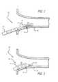
- FIG. 7is a side view with partial cutaway of a catheter system configured in accordance with another embodiment of the invention including an open-lumen ablation catheter having a precurved distal-end region (shown straightened by a guidewire), a steering system and a sidewall orifice and a mapping catheter sized to fit within the ablation catheter and having a normally curved distal-end region (shown straightened);
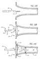
- FIG. 8is an isometric view of the catheter system of FIG. 7 with the distal-end region of the ablation catheter assuming its normally curved shape and the distal-end region of the mapping catheter advanced through the sidewall orifice to assume its normally curved shape;
- FIG. 9Ais a sideview, with partial cutaway of the ablation catheter of FIG. 7 showing the distal-end region in its normally curved state lying in a plane substantially perpendicular to the axis of the proximal-end region of the catheter;
- FIGS. 9A and 9Bare side views of the ablation catheter of FIG. 9A showing the normally curved distal end region deflected by the steering mechanism such that the distal-end region lies in a plane at an angle relative to the axis of the proximal-end region of the catheter.
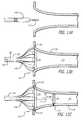
- FIG. 10Adepicts the catheter system of FIG. 7 deployed near the ostium of a vein with the distal-end region of the ablation catheter straightened by a guidewire;
- FIG. 10Bdepicts the catheter system of FIG. 10A with the guidewire removed, the distal-end region of the ablation catheter in its normally curved state and the mapping catheter positioned within the ablation catheter;
- FIG. 10Cdepicts the catheter system of FIG. 10B with the distal-end region of the mapping catheter extending through the orifice of the ablation catheter and in its normally curved state;
- FIG. 11is a cross-sectional side view of a catheter system configured in accordance with another embodiment of the invention including an open-lumen ablation catheter having an expandable distal-end region (shown collapsed) and a mapping catheter sized to fit within the ablation catheter and having a normally curved distal-end region (shown straightened);
- FIG. 12is an isometric view of the catheter system of FIG. 11 with the distal-end region of the ablation catheter expanded and the mapping catheter advanced through the lumen to assume its normally curved shape;
- FIG. 13Adepicts the catheter system of FIG. 11 being deployed near the ostium of a vein with the ablation catheter being guided over a guidewire;
- FIG. 13Bdepicts the catheter system of FIG. 13A with the guidewire removed, the distal-end region of the ablation catheter expanded and the mapping catheter positioned within the ablation catheter;
- FIG. 13Cdepicts the catheter system of FIG. 13B with the distal-end region of the mapping catheter extending through the top of the ablation catheter to assume its normally curved shape;
- FIG. 14depicts a catheter system configured in accordance with another embodiment of the invention having an expandable member (shown collapsed) carrying a mapping electrode system at its distal end and an ablation electrode system near its proximal end;
- FIG. 15depicts the catheter of FIG. 14 with the radially expandable member expanded and deployed within a vein
- FIG. 16depicts a catheter system configured in accordance with another embodiment of the invention having a radially expandable member (shown expanded) and carrying a framework having a mapping electrode system at its distal end and an ablation electrode system near its proximal end.
- FIG. 1there is shown a catheter system 10 including an outer ablation catheter 12 having a lumen throughout and an inner mapping catheter 14 configured to fit and slide within the lumen of the outer ablation catheter.
- the catheters 12 , 14may be of various sizes depending on the intended use of the catheter system 10 .
- the outer ablation catheterhas an outside diameter of 2.39 millimeters (0.094 inches) (7 French) and the inner mapping catheter has an outside diameter of 1.67 millimeters (0.0657 inches) (5 French).
- the energy generator/processor 16is adapted to provide energy to an ablation electrode system 18 located at the distal-end region 20 of the outer ablation catheter 12 and to monitor the temperature at the ablation electrode system.
- Electrically connected to the inner mapping catheter 14is a mapping processor 22 adapted to receive electrical signals from a mapping electrode system 24 located at the distal-end region 26 of the inner mapping catheter. Details regarding the ablation electrode system 18 , the mapping electrode system 24 and their respective electrical connections are provided below.
- the inner mapping catheter 14includes a catheter handle 28 attached to a proximal end 30 of a mapping catheter sheath 32 .
- a first steering tendon 36 and a second steering tendon 38housed within the mapping catheter sheath 32 are a first steering tendon 36 and a second steering tendon 38 .
- the first steering tendon 36 and the second steering tendon 38exit the proximal end of the catheter sheath 32 and enter the catheter handle 28 .
- the first 36 and second 38 steering tendonsattach to a steering controller 40 .
- the distal ends of the steering tendons 36 , 38are attached to a distal-end region 26 of the inner mapping catheter 14 .
- the profile of the distal-end region 26 of the mapping catheter sheath 32can be adjusted by rotating the steering controller 40 .
- the steering controller 40can be rotated by rotating a knob 42 either clockwise or counterclockwise. Rotating the knob 42 clockwise from a neutral position causes one of the steering tendons 36 , 38 to translate axially in the proximal direction, thus creating a first changed profile 44 of the distal-end region 26 .
- rotating the knob 42 counterclockwise from a neutral positioncauses the other steering tendon 36 , 38 to translate axially in the proximal direction, thus creating a second changed profile 46 of the distal-end region 26 .
- FIG. 1depicts the handle 28 being used with a dual-profile catheter with two steering tendons 36 , 38 , the handle is also functional for single-profile catheters with a single steering tendon.
- the ablation electrode system 18includes one or more band electrodes 48 arranged in a linear array. In a preferred embodiment, the ablation electrode system 18 includes three, 3 millimeter wide band electrodes spaced 4 millimeters apart.
- a plurality of feed wiresextend through wire lumen (not shown) running the length of the ablation catheter sheath 34 .
- the wiresare electrically connected to the ablation electrodes 48 at their distal ends and to an electrical connector 49 at their proximal ends.
- the electrical connector 49provides the interface between the energy generator/processor 16 and the lead wires.
- the lead wirestransfer energy from the energy generator/processor 16 to the band electrodes 48 .
- the lead wiresmay also provide temperature signals to the energy generator/processor 16 .
- the mapping electrode system 24includes a plurality of band electrodes 50 and a tip electrode 51 arranged in a linear array.
- the band electrodes 50are spaced close together for high resolution and in a preferred embodiment includes eight 1 millimeter wide band electrodes spaced 1 millimeter apart.
- a plurality of lead wiresextend through the mapping catheter sheath 32 .
- the wiresare electrically connected to the mapping electrodes 50 , 51 at their distal ends and to an electrical connector (not shown) at the rear of the handle 28 at their proximal ends.
- the electrical connectorprovides the interface between the mapping processor 22 and the lead wires.
- the lead wirestransfer electrical signals to the mapping processor.
- the distal-end region 26 of the mapping catheter sheath 32is made more rigid than the distal-end region 20 of the ablation catheter sheath 34 . This may be accomplished, for example, by forming the distal-end region 26 of the mapping catheter sheath 32 of a higher durometer than the distal-end region 20 of the ablation catheter sheath 34 . As such, the distal-end region 20 of the outer ablation catheter 12 assumes the shape of the distal-end region 26 of the inner mapping catheter 14 .
- a seal(not shown) is included in the outer ablation catheter.
- the sealis a soft rubber short-length tubing or O-ring formed of an elastomeric material, e.g., silicon, Santoprene, Viton, and is adhered to the inside diameter of the outer ablation catheter 12 lumen near the distal end.
- the sealforms a tight seal against the outer surface of the inner mapping catheter 14 .
- the sealis pliable enough to allow for movement of the outer ablation catheter 12 relative to the inner mapping catheter 14 yet rigid enough to function as a seal.
- the outer ablation catheter 12also includes a locking mechanism 47 for locking the outer ablation catheter to the inner mapping catheter 14 .
- a locking mechanism 47for locking the outer ablation catheter to the inner mapping catheter 14 .
- An example of one such locking mechanismis described in U.S. application Ser. No. 09/746,721 the disclosure of which is hereby incorporated by reference.
- the systemmay be used for treatment of other locations both within and outside of the heart.
- the catheter system 10may be initially placed within the subject biological site using the steering system of the inner mapping catheter 14 .
- the outer ablation catheter 12 and the inner mapping catheter 14are positioned relative each other such that their distal ends are substantially aligned.
- the catheters 12 , 14are then introduced into a patient's vascular system and are guided therethrough and into the desired biological site, using the mapping catheter's steering system.
- the catheter system 10may be initially placed within the left atrium through a transseptal approach using a guiding sheath (not shown). Once positioned, the guiding sheath and the catheter system 10 are moved relative to each other to expose the distal end regions 20 , 26 of the catheter system 10 .
- the outer ablation catheter 12 and the inner mapping catheter 14are positioned in the left atrium near the pulmonary vein 52 , the outer ablation catheter is retracted in the proximal direction relative to the inner mapping catheter to expose the distal-end region 26 of the inner mapping catheter.
- the distal-end region 26is guided into the vein and is positioned against the tissue 56 defining the vein lumen.
- the profile of the distal-end region 26 of the inner mapping catheter 14may be deflected using the steering system to ensure better contact between the mapping electrode system 24 and the tissue 56 .
- Electrical signals traveling through the tissue 56are sensed by the mapping electrode system 24 and are sent to the mapping processor 22 (FIG. 1) for analysis.
- the mapping electrode system 24is repositioned and then the process is repeated until the foci 54 of the arrthymia are located.
- the outer ablation catheter 12is advanced distally over the inner mapping catheter 14 until the ablation electrode system 18 is at or near the foci 54 . Because the distal-end region 20 of the outer ablation catheter 14 is more pliable than the inner mapping catheter 12 , it assumes the shape of the mapping catheter and is thus placed at or near the foci 54 .
- markersare placed on both the inner mapping catheter 14 and outer ablation catheter 12 . Under fluoroscopy, the markers are used to align the ablation electrode system 18 with the mapping electrode system 24 and hence with the foci 54 . Once properly positioned, energy is applied to the ablation electrode system 18 from the energy generator/processor 16 (FIG. 1 ).
- the energy generator/processor 16provides RF energy.
- other forms of energymay be applied such as cyroablation, light, radiation, laser and any other energy capable of permanently disrupting the electrical continuity of the pulmonary vein 52 .
- the RF energypasses through the ablation electrode system 18 into the tissue 56 at or near the foci 54 to ablate the tissue.
- the catheter system 10includes an inner ablation catheter 58 having an ablation electrode system 60 and an outer mapping catheter 62 having a mapping electrode system 64 .
- the inner ablation catheter 58includes a steering mechanism like that described with reference to the inner mapping catheter 14 (FIG. 1) of the previous embodiment.
- the distal-end region 66 of the outer mapping catheter 62is guided into the vein 52 and is positioned against the tissue 56 defining the vein lumen. Electrical signals traveling through the tissue 56 are sensed by the mapping electrode system 64 and are sent to the mapping processor 22 (FIG. 1) for analysis. The mapping electrode system 64 is repositioned and then the process is repeated until the foci 54 of the arrthymia are located.
- the outer mapping catheter 62is retracted proximally relative to the inner ablation catheter 58 to expose the ablation electrode system 60 at or near the foci 54 .
- the distal-end region 68 of the inner ablation catheter 58is positioned such that it contacts the tissue 56 at or near the foci 54 .
- the distal-end region 68 of the ablation catheter 58may be deflected using the steering system to ensure adequate contact between the ablation electrode system 60 and the tissue 56 .
- energyis applied to the ablation electrode system 60 by the energy generator/processor 16 (FIG. 1) to ablate the tissue 56 at or near the foci 54 .
- the catheter systemincludes an ablation catheter that is specially configured to ablate a circumferential band of tissue near the entry of the pulmonary vein lumen.
- a “circumferential band” as used hereinis a continuous line that is traced around a region of space and which starts and ends at substantially the same location.
- the catheter systemalso includes a mapping catheter that is also specially configured to circumscribe a band of tissue within the vein lumen.
- one such catheter system 80includes an outer ablation catheter 82 having a tubular wall 84 defining a lumen 86 .
- the lumen 86extends between the distal end 88 and proximal end (not shown) of the tubular wall 84 .
- the tubular wall 84has a distal-end region 90 that carries an ablation electrode system 92 .
- the ablation electrode system 92includes a plurality of band electrodes 94 and a tip electrode 96 .
- the lumen 86extends through the tip electrode 92 to allow for placement of the ablation catheter 82 over a guidewire 98 . In an alternate configuration the ablation catheter 82 is guided through a sheath.
- the tubular wall 84includes an orifice 100 positioned within a junction section 102 located between the distal-end region 90 and the proximal-end region 104 .
- the catheter system 80further includes an inner mapping catheter 106 configured to fit into and slide within the lumen 86 of the outer ablation catheter 80 and to fit through the orifice 100 contained within the tubular wall 84 .
- the inner mapping catheter 106includes a tubular wall 108 having a distal-end region 110 that carries a mapping electrode system 112 .
- the mapping electrode system 112includes a plurality of band electrodes 114 and a tip electrode 116 .
- the distal-end regions 90 , 110 of both the ablation catheter 82 and the mapping catheter 106respectively are formed such that they normally assume an arc shape that nearly forms a complete circle having a radius of curvature.
- the respective arcs formed in the distal-end regions 90 , 110each lie in a plane substantially parallel to each other.
- the electrodes 114 , 116 carried by the mapping catheter 106 and the electrodes 94 , 96 carried by the ablation catheter 82circumscribe a predefined circle or partial circle.
- the arc of the ablation catheter 82is sized to fit around all or part of a vein ostium while the arc of the mapping catheter 110 is sized to fit within the vein.
- Catheters having different sized arcsmay be used depending on the particular anatomy being treated.
- the arc shapeis provided by shaped-memory nitinol stylets (not shown) carried within the tubular walls 84 , 108 of the catheters at the distal-end regions 90 , 110 .
- the shaped-memorymay be provided by heat-setting the polymer of the catheter.
- the tubular walls 84 , 108 of the catheterseach include a lumen (not shown) that carries a tendon 85 , 109 .
- the distal end of the ablation catheter tendon 85is attached to the distal tip of the tubular wall 84 near the tip electrode 96 .
- the distal end of the mapping tendon 109is attached to the tubular wall 108 near the tip electrode 116 .
- the proximal end of each tendon 85 , 109is attached to a steering mechanism, such as that shown in FIG. 1 . Applying tension to the tendons 85 , 109 along the length of the catheter shaft causes the radius of curvature of the respective distal-end regions 90 , 110 to tighten, i.e., become smaller. Subsequent removal of tension from the tendons 85 , 109 allows the distal-end regions 90 , 110 to assume their preformed radius of curvature.
- the distal-end regions 90 , 110 of both catheters 82 , 106are resiliently deformable and may assume a linear shape when forced to. More specifically, as shown in FIG. 7, the distal-end region 90 of the ablation catheter 82 assumes a linear shape when it is positioned over a guidewire 98 . With regard to the mapping catheter 106 , its distal-end region 110 assumes a linear shape when it is positioned within the lumen 86 of the ablation catheter 82 .
- the junction section 102 positioned between the distal-end region 90 and the proximal-end region 104 of the ablation catheter 82is formed of a resiliently deformable material, such as Pebax, Nylon or Urethane.
- the junction section 102is normally bent to an angle of approximately 90 degrees.
- the orifice 100is positioned such that its center is generally aligned with the axis 87 of the proximal-end region 104 (FIG. 7) of the tubular wall 84 .
- the mapping catheter 106is similarly configured to include a bend like that of the ablation catheter 82 .
- the ablation catheter 82(FIG. 7) includes a steering mechanism for deflecting the distal-end region 90 .
- the steering mechanismincludes an anchor band 118 positioned within the junction section 102 , proximal to the orifice 100 .
- the anchor band 118is secured to the inner surface of the junction section 102 or to a support mechanism (not shown) attached to the distal-end region 90 .
- the steering mechanismfurther includes a first steering tendon 120 and a second steering tendon 122 , each attached at their distal ends to the anchor band 118 .
- the proximal ends of the tendons 120 , 122exit the proximal end of the tubular wall 84 where they are attached to a steering controller similar to that shown in FIG. 1 .
- the ablation catheter 82is introduced into a patient's vascular system and is guided therethrough and into the heart using a guidewire 98 .
- the catheter 82has been advanced into the left atrium of the patient's heart through the septum, and is now directed towards the pulmonary vein that connects to the left atrium of the heart.
- the ablation catheter 82may be guided into the heart through a sheath.
- the ablation catheter and guidewire 98are moved relative each other such that the distal-end region 90 of the ablation catheter 82 is no longer constrained to a straight position by the guidewire and assumes its normally arced shape.
- the ablation electrode system 92is then positioned at the ostium 124 of the pulmonary vein.
- the mapping catheter 106is guided through the lumen 86 of the ablation catheter 82 toward the orifice 100 in the tubular wall 84 .
- the distal-end region 110 of the mapping catheter 106is formed of a material less rigid than the proximal-end region of ablation catheter 82 . As such the normally arced shape of the distal-end region 10 assumes the shape of the proximal-end region 104 of the ablation catheter 82 .
- the distal-end region 110 of the mapping catheter 106passes through the orifice 100 and is no longer constrained by the proximal-end region 104 of the ablation catheter 82 , it assumes its normally arced shape.
- the distal-end region 110is advanced into the pulmonary vein 126 until the mapping electrode system 112 contacts the tissue 128 .
- Electrical signalsi.e., pulmonary vein potentials, are sensed by the mapping electrode system 112 and sent to the mapping processor where they are analyzed to determine if the pulmonary vein contains an arrthymogenic origin for atrial arrhythmia.
- the ablation electrode system 92is positioned such that it circumferentially engages the tissue around the pulmonary vein ostium 124 . Energy is then applied to the ablation electrode system 92 to ablate the tissue around the ostium 124 to thereby form a circumferential lesion 132 which blocks electrical conduction from the arrthymogenic origin 130 along the pulmonary vein 126 wall into the left atrium. To ensure the formation of a continuous circumferential lesion 132 , energy may be applied to the ablation electrode system 92 using a combination unipolar/bipolar technique and/or phasing technique such as that described in U.S. Pat. Nos. 6,050,994, 6,059,778 and 6,171,305, the disclosures of which are hereby incorporated by reference.
- the distal-end region 110 of the mapping catheter 106 and the distal-end region 90 of the ablation catheter 82may be positioned relative each other such that the mapping electrodes 114 , 116 align with the ablation electrodes 94 , 96 .
- the catheter mapping electrodesmay be positioned such that the tip electrode 116 aligns with the ablation tip electrode 96 , the mapping band electrode 114 adjacent the mapping tip electrode aligns with the ablation band electrode 94 adjacent the ablation tip electrode and so on.
- Alignment of the electrodes 94 , 96 , 114 , 116may be accomplished using a marker visible under fluoroscopy located on the shafts of the catheter. Using a marker allows for the mapping catheter 106 and the ablation catheter 82 to rotate relative each other.
- alignment of the electrodes 94 , 96 , 114 , 116may be accomplished by a guide system carried by the catheter system.
- the guide systemmay include a linear groove (not shown) along the interior of the proximal-end region 104 of the ablation catheter 82 and a complimentary linear protrusion (not shown) along the exterior of the proximal-end region of the mapping catheter 106 .
- the protrusionis positioned within the groove to align the catheter such that their respective electrodes are aligned.
- the groovemay be carried by the mapping catheter 106 and the protrusion by the ablation catheter 82 . In this case, the catheters 82 and 106 are not free to rotate relative to each other.
- a catheter system 140includes an outer ablation catheter 142 having an expandable ablation electrode system 144 .
- the ablation catheter 142includes an outer tubular member 146 and an inner tubular member 148 slidably disposed within the outer tubular member.
- the inner tubular member 148defines an outer-catheter lumen 150 .
- the outer ablation catheter 142further includes a plurality of outwardly bendable segments 152 that, in this embodiment, take the form of elongated strips.
- Each segment 152is secured at its distal end 154 to the distal end 156 of the inner tubular member 148 and at its proximal end 158 to the outer tubular member 146 at a point proximal the attachment points of the distal ends. Configured as such, movement of the inner tubular member 148 in the proximal direction relative the outer tubular member 146 causes the segments 152 to bend outward, as shown in FIG. 12 .
- the width of the strips 152depends on the number required to be placed about the catheter. The more strips that are required, the narrower each one may be. However, there may be a maximum width regardless of how few strips exist. Further, the strips may not be “elongated” but may be shorter in length depending on the radius desired to be obtained when the strips are bent outward.
- An ablation electrode 160is located on each of the segments 152 .
- Lead wires(not shown) run the length of the ablation catheter 142 and connect the ablation electrodes 160 to an energy generator/processor such as that shown in FIG. 1 .
- the lead wiresare carried by a lumen (not shown) contained within the outer tubular member 146 and the bendable segments 152 .
- the catheter system 140further includes an inner mapping catheter 162 configured to fit and slide within the outer-catheter lumen 150 .
- the inner mapping catheter 162includes a tubular wall 164 having a distal-end region 166 that carries a mapping electrode system 168 .
- the mapping electrode system 168includes a plurality of band electrodes 170 and a tip electrode 176 .
- the distal-end region 166 of the tubular wall 164has shaped-memory properties and is formed to normally assume an arc shape that nearly forms a complete circle as shown in FIG. 12 .
- the distal-end region 166 of the mapping catheter 162is less rigid than the inner tubular member 148 of the ablation catheter 142 and assumes the shape of the inner tubular member when it is positioned therein.
- the configuration of the mapping catheter 162is similar to that of FIG. 7 .
- the ablation catheter 142is introduced into a patient's vascular system and is guided therethrough and into the heart using a guidewire 174 .
- the ablation catheter 142may be guided into the heart through a sheath.
- the guidewire 174is removed and the inner tube 148 (FIG. 11) of the ablation catheter 142 is retracted relative to the outer tube 146 , thereby causing the ablation electrode system 144 to assume its expanded form as shown in FIG. 13 B.
- the ablation electrode system 144is then positioned at the ostium 124 of the pulmonary vein 126 , such that the ablation electrodes 160 contact the tissue 128 .
- the mapping catheter 162is guided through the lumen 150 (FIG. 11) of the ablation catheter 142 .
- the mapping catheter 162is formed of a material less rigid than the inner tubular member 148 of the ablation catheter 142 , as such the normally arced shape of the distal-end region assumes the shape of the inner tubular member 148 .
- the distal-end region 166 of the mapping catheter 162passes through the top of the inner tubular member 148 , it assumes its normally curved shape.
- the distal-end region 166is advanced into the pulmonary vein until the mapping electrode system 168 contacts the tissue 128 .
- Electrical signalsare sensed by the mapping electrode system 168 and sent to a mapping processor where they are analyzed to determine if the pulmonary vein contains an arrthymogenic origin for atrial arrhythmia.
- the ablation electrode system 144is positioned to ensure that it circumferentially engages the tissue around the pulmonary vein ostium 124 . Energy is then applied to the ablation electrode system 144 to ablate the tissue around the ostium 124 to thereby form a circumferential lesion 132 which blocks electrical conduction from the arrthymogenic origin 130 along the longitudinal axis of the pulmonary vein 126 wall into the left atrium.
- energymay be applied to the ablation electrode system 144 using a combination unipolar/bipolar technique and/or phasing technique such as those described in U.S. Pat. Nos. 6,050,994, 6,059,778 and 6,171,305, the disclosures of which are hereby incorporated by reference.
- a catheter system 200includes a catheter shaft 202 having a radially expandable member 204 at its distal end.
- the expandable member 204comprises an inflatable balloon having a distal-end region 206 and a proximal-end region 208 .
- the balloon 204is configured such that when it is inflated, the outside diameter of the distal-end region 206 is less than the outside diameter of the proximal-end region 208 .
- a plurality of mapping electrodes 210 arranged in an array at the distal end of the balloon 204form a mapping electrode system 212 .
- the mapping electrodes 210may comprise a metallic material deposited on the outer surface of the balloon using known techniques, such as but not limited to plasma depositing, sputter coating or chemical vapor deposition.
- An ablation electrode system 214is positioned at the proximal-end region 208 of the balloon 204 .
- the ablation electrode system 214may comprise one or more ablation electrodes 216 arranged to form a circumferential band around the balloon 204 .
- the ablation electrodes 216may comprise a metallic material deposited on the outer surface of the balloon 204 .
- the catheter shaft 202includes a lumen that allows for deployment of the catheter system 200 over a guide wire 218 .
- the catheter system 200may be deployed through a guiding sheath.
- the distal end of the catheter system 200is guided by a guide wire 218 to the interior of the pulmonary vein 126 .
- the balloon 204is inflated to a level sufficient to force contact between the mapping electrode system 212 and the circumferential wall of the vein 126 .
- the mapping electrodes 210sense pulmonary vein potentials throughout the circumference and depth of the pulmonary vein 126 and pass them to a mapping processor to determine if the pulmonary vein contains an arrthymogenic origin for atrial arrhythmia.
- the balloonis further inflated to force contact between the ablation electrode system 214 and the tissue around the pulmonary vein ostium 124 .
- Energyis then applied to the ablation electrode system 214 to ablate the tissue around the ostium 124 to thereby form a circumferential lesion 132 which blocks electrical conduction from the arrthymogenic origin 130 along the longitudinal axis of the pulmonary vein 126 wall into the left atrium.
- energymay be applied to the ablation electrode system 214 using a combination unipolar/bipolar technique and/or phasing technique such as that described in U.S. Pat. Nos. 6,050,994, 6,059,778 and 6,171,305, the disclosures of which are hereby incorporated by reference.
- a single balloonis used to deploy both the mapping electrode system and the ablation electrode system.
- the catheter systememploy multiple balloons. A first balloon deploys the mapping electrode system while a second balloon deploys the ablation electrode system.
- the expandable member 242comprises a matrix framework 244 or mesh positioned on an inflatable device 246 , such as a balloon.
- the framework 244is secured to the balloon 246 through known adhesive bonding techniques and is expanded by inflation of the balloon.
- the construction of the framework 244determines the size of its expansion. Specifically, a more “loose” framework 244 allows for greater expansion.
- Mapping electrodes 248 and ablation electrodes 250are mounted on the framework 244 at the distal-end region 252 and the proximal-end region 254 , respectively to define a mapping electrode system 256 and an ablation electrode system 258 .
- the ablation electrodes 250are positioned adjacent each other in a single row around the balloon 246 to form a circumferential electrode band. By using only a single row of electrodes 250 , a narrow ablation band is provided, as such, the ablation site is localized and the risk of pulmonary vein stenosis is minimized. In alternative configurations, more rows of ablation electrodes 250 may be added to increase the width of the ablation band circumference.
- the mapping electrodes 248 and ablation electrodes 250are isolated from each other by insulating coatings on the balloon 246 and/or on the framework 244 .
- the framework 244includes metallic and non-metallic portions.
- a first metallic portioncontains the mapping electrodes 248 while a second metallic portion contains the ablation electrodes 250 .
- Conductive wires carried by the metallic portionsserve as lead wires between the electrodes 248 , 250 and the catheter shaft 262 .
- the lead wiresare carried within the wall of the expandable member 242 and into the catheter shaft 262 .
- the lead wiresare carried by the wall of the catheter shaft 262 to the proximal end of the catheter.
- the metallic portionsare separated by a non-metallic portion 260 .
- the non-metallic portionis formed from PTFE or other non-thrombogenic material.
- deployment of the frameworkcould be through the use of mechanical means such as a spring tension or a deployment tendon/wire to expand and contract the framework.
Landscapes
- Health & Medical Sciences (AREA)
- Life Sciences & Earth Sciences (AREA)
- Surgery (AREA)
- Engineering & Computer Science (AREA)
- Plasma & Fusion (AREA)
- Medical Informatics (AREA)
- Otolaryngology (AREA)
- Physics & Mathematics (AREA)
- Cardiology (AREA)
- Biomedical Technology (AREA)
- Heart & Thoracic Surgery (AREA)
- Nuclear Medicine, Radiotherapy & Molecular Imaging (AREA)
- Molecular Biology (AREA)
- Animal Behavior & Ethology (AREA)
- General Health & Medical Sciences (AREA)
- Public Health (AREA)
- Veterinary Medicine (AREA)
- Surgical Instruments (AREA)
- Measurement And Recording Of Electrical Phenomena And Electrical Characteristics Of The Living Body (AREA)
Abstract
Description
The invention relates generally to an electrophysiological (“EP”) catheter system for use on biological tissue within a biological site, and more particularly, to a combined mapping and ablating catheter system for use in and around the pulmonary veins.
The heart beat in a healthy human is controlled by the sinoatrial node (“S-A node”) located in the wall of the right atrium. The S-A node generates electrical signal potentials that are transmitted through pathways of conductive heart tissue in the atrium to the atrioventricular node (“A-V node”) which in turn transmits the electrical signals throughout the ventricle by means of the His and Purkinje conductive tissues. Improper growth of, or damage to, the conductive tissue in the heart can interfere with the passage of regular electrical signals from the S-A and A-V nodes. Electrical signal irregularities resulting from such interference can disturb the normal rhythm of the heart and cause an abnormal rhythmic condition referred to as “cardiac arrhythmia.”
Cardiac arrhythmia, including atrial arrhythmia, may be of a multiwavelet reentrant type, characterized by multiple asynchronous loops of electrical impulses that are scattered about the atrial chamber and are often self propagating. In the alternative or in addition to the multiwavelet reentrant type, cardiac arrhythmia may also have a focal origin, such as when an isolated region of tissue in an atrium fires autonomously in a rapid, repetitive fashion.
While there are different treatments for cardiac arrhythmia, including the application of anti-arrhythmia drugs, in many cases ablation of the damaged tissue can restore the correct operation of the heart. Such ablation can be performed by percutaneous ablation, a procedure in which a catheter is percutaneously introduced into the patient and directed through an artery or vein to the atrium or ventricle of the heart to perform single or multiple diagnostic, therapeutic, and/or surgical procedures. In such case, an ablation procedure is used to destroy the tissue causing the arrhythmia in an attempt to remove the electrical signal irregularities or create a conductive tissue block to restore normal heart beat or at least an improved heart beat. Successful ablation of the conductive tissue at the arrhythmia initiation site usually terminates the arrhythmia or at least moderates the heart rhythm to acceptable levels. A widely accepted treatment for arrhythmia involves the application of RF energy to the conductive tissue.
In the case of atrial fibrillation (“AF”), a procedure published by Cox et al. and known as the “Maze procedure” involves the formation of continuous atrial incisions to prevent atrial reentry and to allow sinus impulses to activate the entire myocardium. While this procedure has been found to be successful, it involves an intensely invasive approach. It is more desirable to accomplish the same result as the Maze procedure by use of a less invasive approach, such as through the use of an appropriate EP catheter system providing RF ablation therapy. In this therapy, transmural ablation lesions are formed in the atria to prevent atrial reentry and to allow sinus impulses to activate the entire myocardium.
One such EP catheter system, as disclosed in U.S. Pat. Nos. 6,059,778 and 6,096,036, includes a plurality of spaced apart band electrodes located at the distal-end of the catheter and arranged in a linear array. The band electrodes are positioned proximal heart tissue. RF energy is applied through the electrodes to the heart tissue to produce a series of long linear lesions similar to those produced by the Maze procedure.
As previously mentioned, cardiac arrhythmia, such as atrial fibrillation, may be focal in nature. The foci, defined by regions exhibiting a consistent and centifugal pattern of electrical activation, may act as either a trigger of atrial fibrillation paroxysmal or may even sustain fibrillation. Such focal arrhythmia are known to originate from a tissue region along the pulmonary veins of the left atrium, and more particularly in the superior pulmonary veins.
Procedures for the treatment of focal arrhythmia involving the pulmonary vein generally require the use of two separate catheter systems—a mapping catheter system for locating the foci and an ablation catheter system for ablating the foci. Both catheter systems include their respective mapping or ablation catheter and either a guiding catheter or a guide wire for introducing the catheter into the left atrium of the heart. During a typical procedure, the mapping catheter is first introduced into the left atrium through a puncture in the septum between the right and left atria. The mapping catheter is then guided into the pulmonary vein. While the mapping catheter is still within the heart, the ablation catheter is introduced into the left atrium through either the same puncture as the mapping catheter or a separate puncture. Using the mapping catheter, the foci of the arrhythmia is located using any of several well known mapping techniques. After it is determined that the foci are located within the pulmonary vein, the ablation catheter is positioned either in the pulmonary vein or around the pulmonary vein ostium and the tissue is ablated. The procedure thus described requires the simultaneous placement of two separate catheters into the left atrium through either one or two separate introduction paths. In the case of the left atrium such introduction paths comprise punctures through the atrial septum between the right and left atria. Passing two catheters through a single puncture or two separate punctures increases patient trauma. It also increases the likelihood of damaging the heart through tearing of the septum.
Hence, those skilled in the art have recognized a need for a catheter system having two independent catheters, each capable of being introduced into the heart via a single transseptal introduction path. The need for a combined mapping and ablation catheter system for use in the pulmonary vein has also been recognized. The invention fulfills these needs and others.
Briefly, and in general terms, the invention is directed to a combination mapping and ablating catheter system for use during electrophysiological procedures in and around various biological sites, including the pulmonary veins.
In a first aspect, the invention relates to a catheter system that includes an outer catheter having a lumen therethrough and a distal-end region carrying a first electrode system. The catheter system also includes an inner catheter that is sized to fit within and slide through the lumen of the outer catheter. The inner catheter has a distal-end region carrying a second electrode system.
By providing an outer catheter having a lumen through which a separate inner catheter may slide, the invention allows for the simultaneous placement of two separate catheters into a biological site through a signal introduction path. As such, the likelihood of damaging the biological site is substantially reduced.
In detailed aspects of the invention, either one or both of the outer catheter and inner catheter further include a tendon having a distal end attached to the distal-end region of the respective catheter and a proximal end exiting the proximal end of the catheter. The tendon is attached such that movement of the tendon along the length of the catheter causes the distal-end region of that catheter to curve. In a another detailed aspect, the outer catheter further comprises a shaped-memory stylet for imparting a preshaped curve to the distal-end region of the outer catheter. In a further detailed aspect, the preshaped curve has a radius of curvature and the catheter further comprises a tendon having a distal end attached to the distal end of the catheter and a proximal end exiting the proximal end of the catheter. The tendon is attached such that movement of the tendon along the length of the catheter decreases the radius of curvature.
In another detailed facet of the invention, the outer catheter includes an outer tubular member and an inner tubular member slidably disposed within the outer tubular member. The inner tubular member defines the lumen of the outer catheter. The other catheter also includes a plurality of outwardly bendable segments. The segments are secured at their distal ends to the distal-end region of the inner tubular member and at their proximal ends to the outer tubular member at a point proximal the attachment points of the distal ends. Movement of the inner tubular member in the proximal direction relative the outer tubular member causes the segments to bend outward.
In another aspect, the invention relates to a catheter system that includes an outer catheter having tubular wall defining a lumen. The tubular wall includes a sidewall orifice. The outer catheter also includes a distal-end region carrying a first electrode system and a proximal-end region. The catheter system further includes an inner catheter sized to fit within the lumen of the outer catheter and to slide therein. The inner catheter is also sized to fit through the sidewall orifice. The inner catheter has a distal-end region carrying a second electrode system.
In a detailed facet of the invention, the tubular member comprises a resiliently deformable junction section between the distal-end region and the proximal end region. The junction section has a normally bent form that generally aligns the center of the sidewall orifice with the axis of the proximal-end region of the tubular wall. In another detailed aspect, the outer catheter further includes a tendon having a distal end attached proximate the inner wall of the tubular member and a proximal end exiting the proximal end of the tubular member. Movement of the tendon along the length of the tubular member causes the distal-end region to deflect about the junction section relative to the proximal-end region. In yet another detailed aspect, the outer catheter includes a shaped-memory stylet for imparting a generally circular curve to the distal-end region of the tubular wall. The curve lies substantially within a first plane. The inner catheter also includes a shaped-memory stylet for imparting a generally circular curve to the distal-end region of the inner catheter. This curve lies substantially within a second plane that is substantially parallel to the first plane.
In another detailed facet of the invention the first electrode system and the second electrode system each comprise a plurality of band electrodes positioned along the length of the their respective distal-end region. The catheter system further comprises an alignment system that is adapted to align the curved distal-end region of the inner catheter with the curved distal-end region of the outer catheter such that the band electrodes of the respective catheters are aligned with each other. In a further detailed aspect, the alignment system comprises a pair of markers, each visible under fluoroscopy. One marker is carried on the proximal region of the inner catheter while the other marker is carried on the proximal region of the outer catheter.
In another further detailed aspect, the alignment system comprises a groove along the outer surface of the proximal region of the inner catheter and a complementary protrusion along the inner surface of the outer catheter.
In another facet, the invention relates to a method of performing an electrophysiological procedure on biological tissue within a biological site. The method includes positioning a first catheter, having a distal-end region carrying a first electrode system, within the biological site proximate the biological tissue. The method further includes sensing electrical activity within the tissue through the first electrode system and processing the electrical activity to identify the origin of an electrophysiological condition. The method further includes guiding a second catheter, having a distal-end region carrying a second electrode system, via the first catheter, into the biological site. The method also includes positioning the second catheter such that the second electrode system is adjacent the identified origin and applying energy to the second electrode system to ablate the identified origin.
In a detailed aspect of the invention, the first catheter includes a tubular wall defining a lumen and guiding the second catheter includes sliding the second catheter through the lumen. In a further detailed facet, positioning the second catheter such that the second electrode system is adjacent the identified source includes sliding the second catheter through the lumen until the second electrode system is substantially coincident with the first electrode system and repositioning the first catheter relative the second catheter to expose the second electrode system. In another detailed aspect, the second catheter includes a tubular wall defining a lumen and guiding the second catheter includes sliding the second catheter over the first catheter. In a further detailed aspect, positioning the second catheter such that the second electrode system is adjacent the identified source includes sliding the second catheter over the first catheter until the second electrode system is coincident with the first electrode system.
In another facet, the invention relates to a method of performing an electrophysiological procedure on biological tissue proximate a pulmonary vein. The method includes positioning a first catheter, having a distal-end region carrying a first electrode system, near the ostium of the pulmonary vein and guiding a second catheter, via the first catheter, into the pulmonary vein. The second catheter has a distal-end region carrying a second electrode system. The method further includes sensing electrical activity within the pulmonary-vein tissue through the first electrode system, processing the electrical activity to confirm the existence of an abnormal electrophysiological condition originating within the pulmonary vein and upon confirmation, applying energy to the first electrode system to ablate the tissue near the ostium.
In a detailed facet of the invention, the first catheter further includes a resiliently deformable shaped-memory stylet for imparting a generally circular curve to the distal-end region of the first catheter and positioning the first catheter near the ostium of the pulmonary vein includes the steps of straightening the distal-end region to allow entry of the distal-end region into the heart, allowing the distal-end region to assume its curved shape and positioning the distal-end region at the ostium such that the curved portion of the region contacts the tissue defining the ostium. In another detailed aspect, the second catheter further includes a resiliently deformable shaped-memory stylet for imparting a generally circular curve to the distal-end region of the second catheter and positioning the second catheter within the pulmonary vein includes the steps of straightening the distal-end region to allow entry of the distal-end region into the pulmonary vein, allowing the distal-end region to assume its curved shape and positioning the distal-end region within the vein such that the curved portion of the region contacts the tissue defining the vein lumen.
In another aspect, the invention relates to a catheter system including a catheter sheath carrying a circumferentially expandable member at its distal end. The catheter system further includes a first electrode system positioned on the expandable member and a second electrode system positioned on the expandable member, proximal the first electrode system.
In a detailed aspect of the invention, the expandable member includes a distal segment with a first expandable diameter and a proximal segment with a second expandable diameter greater than the first expandable diameter. The first electrode system is positioned at the distal segment and the second electrode system positioned at the proximal segment. In further detailed aspects either one or both of the first electrode system and second electrode system includes a plurality of electrode elements arranged to form a circumferential band around the expandable member.
In another aspect, the invention relates to a method of performing an electrophysiological procedure on biological tissue proximate a pulmonary vein. The method includes positioning a circumferentially expandable member having a distal-end region with a first electrode system and a proximal-end region with a second electrode system in the heart such that the distal-end region is at least partially within the pulmonary vein and the proximal-end region is adjacent the tissue defining the ostium of the pulmonary vein. The method also includes expanding the circumferentially expandable member such that the first electrode system contacts the tissue defining the pulmonary vein and the second electrode system contacts the tissue defining the ostium, sensing electrical activity within the pulmonary-vein tissue through the first electrode system and processing the electrical activity to confirm the existence of an abnormal electrophysiological condition originating within the pulmonary vein. The method further includes applying energy to the first electrode system to ablate the tissue near the ostium upon confirmation of the existence of an abnormal electrophysiological condition.
These and other aspects and advantages of the invention will become apparent from the following detailed description and the accompanying drawings which illustrate by way of example the features of the invention.
FIG. 1 depicts a catheter system configured in accordance with one embodiment of the invention including a mapping catheter slidably positioned within an open-lumen ablation catheter;
FIG. 2 depicts the catheter system of FIG. 1 positioned near the ostium of a vein with the ablation catheter retracted to exposed the mapping catheter such that the mapping catheter may locate the focal origin of an arrhythmia;
FIG. 3 depicts the catheter system of FIG. 2 positioned near the ostium of a vein with the ablation catheter advanced to coincide with the focal origin previously located by the mapping catheter;
FIG. 4 depicts the distal-end region of an alternate configuration of the catheter of FIG. 1 wherein the ablation catheter is slidably positioned within an open-lumen mapping catheter;
FIG. 5 depicts the catheter system of FIG. 4 positioned near the ostium of a vein with the mapping catheter advanced over the ablation catheter such that the mapping catheter may locate the focal origin of an arrhythmia;
FIG. 6 depicts the catheter system of FIG. 5 positioned near the ostium of a vein with the mapping catheter retracted to allow the ablation catheter to coincide with the focal origin previously located by the mapping catheter;
FIG. 7 is a side view with partial cutaway of a catheter system configured in accordance with another embodiment of the invention including an open-lumen ablation catheter having a precurved distal-end region (shown straightened by a guidewire), a steering system and a sidewall orifice and a mapping catheter sized to fit within the ablation catheter and having a normally curved distal-end region (shown straightened);
FIG. 8 is an isometric view of the catheter system of FIG. 7 with the distal-end region of the ablation catheter assuming its normally curved shape and the distal-end region of the mapping catheter advanced through the sidewall orifice to assume its normally curved shape;
FIG. 9A is a sideview, with partial cutaway of the ablation catheter of FIG. 7 showing the distal-end region in its normally curved state lying in a plane substantially perpendicular to the axis of the proximal-end region of the catheter;
FIGS. 9A and 9B are side views of the ablation catheter of FIG. 9A showing the normally curved distal end region deflected by the steering mechanism such that the distal-end region lies in a plane at an angle relative to the axis of the proximal-end region of the catheter.
FIG. 10A depicts the catheter system of FIG. 7 deployed near the ostium of a vein with the distal-end region of the ablation catheter straightened by a guidewire;
FIG. 10B depicts the catheter system of FIG. 10A with the guidewire removed, the distal-end region of the ablation catheter in its normally curved state and the mapping catheter positioned within the ablation catheter;
FIG. 10C depicts the catheter system of FIG. 10B with the distal-end region of the mapping catheter extending through the orifice of the ablation catheter and in its normally curved state;
FIG. 11 is a cross-sectional side view of a catheter system configured in accordance with another embodiment of the invention including an open-lumen ablation catheter having an expandable distal-end region (shown collapsed) and a mapping catheter sized to fit within the ablation catheter and having a normally curved distal-end region (shown straightened);
FIG. 12 is an isometric view of the catheter system of FIG. 11 with the distal-end region of the ablation catheter expanded and the mapping catheter advanced through the lumen to assume its normally curved shape;
FIG. 13A depicts the catheter system of FIG. 11 being deployed near the ostium of a vein with the ablation catheter being guided over a guidewire;
FIG. 13B depicts the catheter system of FIG. 13A with the guidewire removed, the distal-end region of the ablation catheter expanded and the mapping catheter positioned within the ablation catheter;
FIG. 13C depicts the catheter system of FIG. 13B with the distal-end region of the mapping catheter extending through the top of the ablation catheter to assume its normally curved shape;
FIG. 14 depicts a catheter system configured in accordance with another embodiment of the invention having an expandable member (shown collapsed) carrying a mapping electrode system at its distal end and an ablation electrode system near its proximal end;
FIG. 15 depicts the catheter of FIG. 14 with the radially expandable member expanded and deployed within a vein; and
FIG. 16 depicts a catheter system configured in accordance with another embodiment of the invention having a radially expandable member (shown expanded) and carrying a framework having a mapping electrode system at its distal end and an ablation electrode system near its proximal end.
Turning now to the drawings, in which like reference numerals are used to designate like or corresponding elements among the several figures, in FIG. 1 there is shown acatheter system 10 including anouter ablation catheter 12 having a lumen throughout and aninner mapping catheter 14 configured to fit and slide within the lumen of the outer ablation catheter. Thecatheters catheter system 10. In one configuration of a catheter system intended for use within the heart, and particularly, the pulmonary vein, the outer ablation catheter has an outside diameter of 2.39 millimeters (0.094 inches) (7 French) and the inner mapping catheter has an outside diameter of 1.67 millimeters (0.0657 inches) (5 French).
Electrically connected to theouter ablation catheter 12 is an energy generator/processor 16. The energy generator/processor 16 is adapted to provide energy to anablation electrode system 18 located at the distal-end region 20 of theouter ablation catheter 12 and to monitor the temperature at the ablation electrode system. Electrically connected to theinner mapping catheter 14 is amapping processor 22 adapted to receive electrical signals from amapping electrode system 24 located at the distal-end region 26 of the inner mapping catheter. Details regarding theablation electrode system 18, themapping electrode system 24 and their respective electrical connections are provided below.
With continued reference to FIG. 1, theinner mapping catheter 14 includes acatheter handle 28 attached to aproximal end 30 of amapping catheter sheath 32. Housed within themapping catheter sheath 32 are afirst steering tendon 36 and asecond steering tendon 38. Thefirst steering tendon 36 and thesecond steering tendon 38 exit the proximal end of thecatheter sheath 32 and enter thecatheter handle 28. Within thecatheter handle 28, the first36 and second38 steering tendons attach to asteering controller 40. The distal ends of thesteering tendons end region 26 of theinner mapping catheter 14.
With further reference to FIG. 1, the profile of the distal-end region 26 of themapping catheter sheath 32 can be adjusted by rotating thesteering controller 40. The steeringcontroller 40 can be rotated by rotating aknob 42 either clockwise or counterclockwise. Rotating theknob 42 clockwise from a neutral position causes one of thesteering tendons profile 44 of the distal-end region 26. Similarly, rotating theknob 42 counterclockwise from a neutral position causes theother steering tendon profile 46 of the distal-end region 26. Although FIG. 1 depicts thehandle 28 being used with a dual-profile catheter with two steeringtendons
Theablation electrode system 18 includes one ormore band electrodes 48 arranged in a linear array. In a preferred embodiment, theablation electrode system 18 includes three, 3 millimeter wide band electrodes spaced 4 millimeters apart. A plurality of feed wires (not shown) extend through wire lumen (not shown) running the length of theablation catheter sheath 34. The wires are electrically connected to theablation electrodes 48 at their distal ends and to anelectrical connector 49 at their proximal ends. Theelectrical connector 49 provides the interface between the energy generator/processor 16 and the lead wires. The lead wires transfer energy from the energy generator/processor 16 to theband electrodes 48. The lead wires may also provide temperature signals to the energy generator/processor 16.
Themapping electrode system 24 includes a plurality ofband electrodes 50 and atip electrode 51 arranged in a linear array. Theband electrodes 50 are spaced close together for high resolution and in a preferred embodiment includes eight 1 millimeter wide band electrodes spaced 1 millimeter apart. A plurality of lead wires (not shown) extend through themapping catheter sheath 32. The wires are electrically connected to themapping electrodes handle 28 at their proximal ends. The electrical connector provides the interface between themapping processor 22 and the lead wires. The lead wires transfer electrical signals to the mapping processor.
To assist in steering thecatheter system 10 through the patient's vascular system and to assure proper placement of theablation electrode system 18, the distal-end region 26 of themapping catheter sheath 32 is made more rigid than the distal-end region 20 of theablation catheter sheath 34. This may be accomplished, for example, by forming the distal-end region 26 of themapping catheter sheath 32 of a higher durometer than the distal-end region 20 of theablation catheter sheath 34. As such, the distal-end region 20 of theouter ablation catheter 12 assumes the shape of the distal-end region 26 of theinner mapping catheter 14.
To prevent fluid from entering the space between the inside wall of theouter ablation catheter 12 and the outside surface of theinner mapping catheter 14, a seal (not shown) is included in the outer ablation catheter. The seal is a soft rubber short-length tubing or O-ring formed of an elastomeric material, e.g., silicon, Santoprene, Viton, and is adhered to the inside diameter of theouter ablation catheter 12 lumen near the distal end. The seal forms a tight seal against the outer surface of theinner mapping catheter 14. The seal is pliable enough to allow for movement of theouter ablation catheter 12 relative to theinner mapping catheter 14 yet rigid enough to function as a seal. Theouter ablation catheter 12 also includes alocking mechanism 47 for locking the outer ablation catheter to theinner mapping catheter 14. An example of one such locking mechanism is described in U.S. application Ser. No. 09/746,721 the disclosure of which is hereby incorporated by reference.
While the operational descriptions to follow focus on the use of thecatheter system 10 for treating focal arrthymias originating within and around the pulmonary vein, the system may be used for treatment of other locations both within and outside of the heart. For procedures not involving the pulmonary vein, thecatheter system 10 may be initially placed within the subject biological site using the steering system of theinner mapping catheter 14. In such placement procedures, theouter ablation catheter 12 and theinner mapping catheter 14 are positioned relative each other such that their distal ends are substantially aligned. Thecatheters catheter system 10 may be initially placed within the left atrium through a transseptal approach using a guiding sheath (not shown). Once positioned, the guiding sheath and thecatheter system 10 are moved relative to each other to expose thedistal end regions catheter system 10.
With reference to FIG. 2, once theouter ablation catheter 12 and theinner mapping catheter 14 are positioned in the left atrium near thepulmonary vein 52, the outer ablation catheter is retracted in the proximal direction relative to the inner mapping catheter to expose the distal-end region 26 of the inner mapping catheter. The distal-end region 26 is guided into the vein and is positioned against thetissue 56 defining the vein lumen. The profile of the distal-end region 26 of theinner mapping catheter 14 may be deflected using the steering system to ensure better contact between themapping electrode system 24 and thetissue 56. Electrical signals traveling through thetissue 56 are sensed by themapping electrode system 24 and are sent to the mapping processor22 (FIG. 1) for analysis. Themapping electrode system 24 is repositioned and then the process is repeated until thefoci 54 of the arrthymia are located.
With reference to FIG. 3, once thefoci 54 are located, theouter ablation catheter 12 is advanced distally over theinner mapping catheter 14 until theablation electrode system 18 is at or near thefoci 54. Because the distal-end region 20 of theouter ablation catheter 14 is more pliable than theinner mapping catheter 12, it assumes the shape of the mapping catheter and is thus placed at or near thefoci 54. In a preferred embodiment, markers (not shown) are placed on both theinner mapping catheter 14 andouter ablation catheter 12. Under fluoroscopy, the markers are used to align theablation electrode system 18 with themapping electrode system 24 and hence with thefoci 54. Once properly positioned, energy is applied to theablation electrode system 18 from the energy generator/processor16 (FIG.1). In a preferred embodiment the energy generator/processor 16 provides RF energy. In alternate embodiments, other forms of energy may be applied such as cyroablation, light, radiation, laser and any other energy capable of permanently disrupting the electrical continuity of thepulmonary vein 52. In the embodiment shown, the RF energy passes through theablation electrode system 18 into thetissue 56 at or near thefoci 54 to ablate the tissue.
With reference to FIG. 4, in an alternate configuration of this embodiment of the invention, thecatheter system 10 includes aninner ablation catheter 58 having anablation electrode system 60 and anouter mapping catheter 62 having amapping electrode system 64. Theinner ablation catheter 58 includes a steering mechanism like that described with reference to the inner mapping catheter14 (FIG. 1) of the previous embodiment.
In operation, as shown in FIG. 5, once theouter mapping catheter 62 and theinner ablation catheter 58 are positioned in the heart, the distal-end region 66 of theouter mapping catheter 62 is guided into thevein 52 and is positioned against thetissue 56 defining the vein lumen. Electrical signals traveling through thetissue 56 are sensed by themapping electrode system 64 and are sent to the mapping processor22 (FIG. 1) for analysis. Themapping electrode system 64 is repositioned and then the process is repeated until thefoci 54 of the arrthymia are located.
With reference to FIG. 6, once thefoci 54 are located, theouter mapping catheter 62 is retracted proximally relative to theinner ablation catheter 58 to expose theablation electrode system 60 at or near thefoci 54. The distal-end region 68 of theinner ablation catheter 58 is positioned such that it contacts thetissue 56 at or near thefoci 54. The distal-end region 68 of theablation catheter 58 may be deflected using the steering system to ensure adequate contact between theablation electrode system 60 and thetissue 56. Once adequately positioned, energy is applied to theablation electrode system 60 by the energy generator/processor16 (FIG. 1) to ablate thetissue 56 at or near thefoci 54.
In other embodiments of the invention the catheter system includes an ablation catheter that is specially configured to ablate a circumferential band of tissue near the entry of the pulmonary vein lumen. A “circumferential band” as used herein is a continuous line that is traced around a region of space and which starts and ends at substantially the same location. The catheter system also includes a mapping catheter that is also specially configured to circumscribe a band of tissue within the vein lumen.
With reference to FIG. 7 onesuch catheter system 80 includes anouter ablation catheter 82 having atubular wall 84 defining alumen 86. Thelumen 86 extends between thedistal end 88 and proximal end (not shown) of thetubular wall 84. Thetubular wall 84 has a distal-end region 90 that carries anablation electrode system 92. In a preferred embodiment, theablation electrode system 92 includes a plurality ofband electrodes 94 and atip electrode 96. Thelumen 86 extends through thetip electrode 92 to allow for placement of theablation catheter 82 over aguidewire 98. In an alternate configuration theablation catheter 82 is guided through a sheath. In such a configuration, the need to extend thelumen 86 through thetip electrode 92 is eliminated. Thetubular wall 84 includes anorifice 100 positioned within ajunction section 102 located between the distal-end region 90 and the proximal-end region 104.
Thecatheter system 80 further includes aninner mapping catheter 106 configured to fit into and slide within thelumen 86 of theouter ablation catheter 80 and to fit through theorifice 100 contained within thetubular wall 84. Theinner mapping catheter 106 includes atubular wall 108 having a distal-end region 110 that carries amapping electrode system 112. In a preferred embodiment, themapping electrode system 112 includes a plurality ofband electrodes 114 and atip electrode 116.
As shown in FIG. 8, the distal-end regions ablation catheter 82 and themapping catheter 106 respectively are formed such that they normally assume an arc shape that nearly forms a complete circle having a radius of curvature. The respective arcs formed in the distal-end regions end regions electrodes mapping catheter 106 and theelectrodes ablation catheter 82 circumscribe a predefined circle or partial circle. The arc of theablation catheter 82 is sized to fit around all or part of a vein ostium while the arc of themapping catheter 110 is sized to fit within the vein. Catheters having different sized arcs may be used depending on the particular anatomy being treated. In one embodiment, the arc shape is provided by shaped-memory nitinol stylets (not shown) carried within thetubular walls end regions
In an alternate configuration, thetubular walls tendon ablation catheter tendon 85 is attached to the distal tip of thetubular wall 84 near thetip electrode 96. Likewise, the distal end of themapping tendon 109 is attached to thetubular wall 108 near thetip electrode 116. The proximal end of eachtendon tendons end regions tendons end regions
Though configured to normally assume their arced shapes, the distal-end regions catheters end region 90 of theablation catheter 82 assumes a linear shape when it is positioned over aguidewire 98. With regard to themapping catheter 106, its distal-end region 110 assumes a linear shape when it is positioned within thelumen 86 of theablation catheter 82.
With continued reference to FIG. 7, thejunction section 102 positioned between the distal-end region 90 and the proximal-end region 104 of theablation catheter 82 is formed of a resiliently deformable material, such as Pebax, Nylon or Urethane. Thejunction section 102 is normally bent to an angle of approximately 90 degrees. When thejunction section 102 is in its normally bent form, as shown in FIG. 8, theorifice 100 is positioned such that its center is generally aligned with theaxis 87 of the proximal-end region104 (FIG. 7) of thetubular wall 84. Themapping catheter 106 is similarly configured to include a bend like that of theablation catheter 82.
In a preferred embodiment, the ablation catheter82 (FIG. 7) includes a steering mechanism for deflecting the distal-end region 90. In one configuration, the steering mechanism includes ananchor band 118 positioned within thejunction section 102, proximal to theorifice 100. Theanchor band 118 is secured to the inner surface of thejunction section 102 or to a support mechanism (not shown) attached to the distal-end region 90. The steering mechanism further includes afirst steering tendon 120 and asecond steering tendon 122, each attached at their distal ends to theanchor band 118. The proximal ends of thetendons tubular wall 84 where they are attached to a steering controller similar to that shown in FIG.1.
With reference to FIG. 9A, when the steering controller is in a neutral position, i.e., no tension is applied to eithertendon end region 90 of theablation catheter 82 lies in a plane substantially perpendicular to theaxis 87 of the proximal-end region 104. With reference to FIG. 9B, when tension is applied to the first steering tendon120 (FIG.9A), the arc formed by the distal-end region 90 of theablation catheter 82 is deflected in a first direction such that the arc lies in a plane at an angle relative to theaxis 87 of the proximal-end region 104. With reference to FIG. 9C, when tension is applied to the second steering tendon122 (FIG.9A), the arc formed by the distal-end region 90 of theablation catheter 82 is deflected in a second direction, opposite the first direction, such that the arc lies in a plane at an angle relative to theaxis 87 of the proximal-end region 104.
With reference to FIG. 10A, in operation, theablation catheter 82 is introduced into a patient's vascular system and is guided therethrough and into the heart using aguidewire 98. As is meant to be shown in FIG. 10A, thecatheter 82 has been advanced into the left atrium of the patient's heart through the septum, and is now directed towards the pulmonary vein that connects to the left atrium of the heart. Alternatively, theablation catheter 82 may be guided into the heart through a sheath. With reference to FIG. 10B, once theablation catheter 82 is positioned in the heart, the ablation catheter and guidewire98 are moved relative each other such that the distal-end region 90 of theablation catheter 82 is no longer constrained to a straight position by the guidewire and assumes its normally arced shape. Theablation electrode system 92 is then positioned at theostium 124 of the pulmonary vein. Once theablation electrode system 92 is positioned, themapping catheter 106 is guided through thelumen 86 of theablation catheter 82 toward theorifice 100 in thetubular wall 84. As previously mentioned, the distal-end region 110 of themapping catheter 106 is formed of a material less rigid than the proximal-end region ofablation catheter 82. As such the normally arced shape of the distal-end region 10 assumes the shape of the proximal-end region 104 of theablation catheter 82.
As shown in FIG. 10C, as the distal-end region 110 of themapping catheter 106 passes through theorifice 100 and is no longer constrained by the proximal-end region 104 of theablation catheter 82, it assumes its normally arced shape. The distal-end region 110 is advanced into thepulmonary vein 126 until themapping electrode system 112 contacts thetissue 128. Electrical signals, i.e., pulmonary vein potentials, are sensed by themapping electrode system 112 and sent to the mapping processor where they are analyzed to determine if the pulmonary vein contains an arrthymogenic origin for atrial arrhythmia.
If it is determined that the pulmonary vein contains anarrthymogenic origin 130, theablation electrode system 92 is positioned such that it circumferentially engages the tissue around thepulmonary vein ostium 124. Energy is then applied to theablation electrode system 92 to ablate the tissue around theostium 124 to thereby form acircumferential lesion 132 which blocks electrical conduction from thearrthymogenic origin 130 along thepulmonary vein 126 wall into the left atrium. To ensure the formation of a continuouscircumferential lesion 132, energy may be applied to theablation electrode system 92 using a combination unipolar/bipolar technique and/or phasing technique such as that described in U.S. Pat. Nos. 6,050,994, 6,059,778 and 6,171,305, the disclosures of which are hereby incorporated by reference.
With reference to FIG. 8, in a preferred embodiment of thecatheter system 80 the distal-end region 110 of themapping catheter 106 and the distal-end region 90 of theablation catheter 82 may be positioned relative each other such that themapping electrodes ablation electrodes tip electrode 116 aligns with theablation tip electrode 96, themapping band electrode 114 adjacent the mapping tip electrode aligns with theablation band electrode 94 adjacent the ablation tip electrode and so on. Alignment of theelectrodes mapping catheter 106 and theablation catheter 82 to rotate relative each other.
Alternatively, alignment of theelectrodes end region 104 of theablation catheter 82 and a complimentary linear protrusion (not shown) along the exterior of the proximal-end region of themapping catheter 106. During deployment of themapping catheter 106 through theablation catheter 82, the protrusion is positioned within the groove to align the catheter such that their respective electrodes are aligned. Alternatively, the groove may be carried by themapping catheter 106 and the protrusion by theablation catheter 82. In this case, thecatheters
With reference to FIG. 11, in another embodiment of the invention, acatheter system 140 includes anouter ablation catheter 142 having an expandableablation electrode system 144. Theablation catheter 142 includes an outertubular member 146 and an innertubular member 148 slidably disposed within the outer tubular member. The innertubular member 148 defines an outer-catheter lumen 150. Theouter ablation catheter 142 further includes a plurality of outwardlybendable segments 152 that, in this embodiment, take the form of elongated strips. Eachsegment 152 is secured at itsdistal end 154 to thedistal end 156 of the innertubular member 148 and at itsproximal end 158 to the outertubular member 146 at a point proximal the attachment points of the distal ends. Configured as such, movement of the innertubular member 148 in the proximal direction relative the outertubular member 146 causes thesegments 152 to bend outward, as shown in FIG.12. The width of thestrips 152 depends on the number required to be placed about the catheter. The more strips that are required, the narrower each one may be. However, there may be a maximum width regardless of how few strips exist. Further, the strips may not be “elongated” but may be shorter in length depending on the radius desired to be obtained when the strips are bent outward.
Anablation electrode 160 is located on each of thesegments 152. Lead wires (not shown) run the length of theablation catheter 142 and connect theablation electrodes 160 to an energy generator/processor such as that shown in FIG.1. The lead wires are carried by a lumen (not shown) contained within the outertubular member 146 and thebendable segments 152.
Thecatheter system 140 further includes aninner mapping catheter 162 configured to fit and slide within the outer-catheter lumen 150. Theinner mapping catheter 162 includes atubular wall 164 having a distal-end region 166 that carries amapping electrode system 168. In a preferred embodiment, themapping electrode system 168 includes a plurality ofband electrodes 170 and atip electrode 176. The distal-end region 166 of thetubular wall 164 has shaped-memory properties and is formed to normally assume an arc shape that nearly forms a complete circle as shown in FIG.12. The distal-end region 166 of themapping catheter 162 is less rigid than the innertubular member 148 of theablation catheter 142 and assumes the shape of the inner tubular member when it is positioned therein. The configuration of themapping catheter 162 is similar to that of FIG.7.
With reference to FIG. 13A, in operation, theablation catheter 142 is introduced into a patient's vascular system and is guided therethrough and into the heart using aguidewire 174. Alternatively, theablation catheter 142 may be guided into the heart through a sheath. Once theablation catheter 142 is positioned in the heart, theguidewire 174 is removed and the inner tube148 (FIG. 11) of theablation catheter 142 is retracted relative to theouter tube 146, thereby causing theablation electrode system 144 to assume its expanded form as shown in FIG.13B. Theablation electrode system 144 is then positioned at theostium 124 of thepulmonary vein 126, such that theablation electrodes 160 contact thetissue 128.
Once theablation electrode system 144 is positioned at the pulmonary vein ostium, themapping catheter 162 is guided through the lumen150 (FIG. 11) of theablation catheter 142. As previously mentioned, themapping catheter 162 is formed of a material less rigid than the innertubular member 148 of theablation catheter 142, as such the normally arced shape of the distal-end region assumes the shape of the innertubular member 148.
As shown in FIG. 13C, as the distal-end region 166 of themapping catheter 162 passes through the top of the innertubular member 148, it assumes its normally curved shape. The distal-end region 166 is advanced into the pulmonary vein until themapping electrode system 168 contacts thetissue 128. Electrical signals are sensed by themapping electrode system 168 and sent to a mapping processor where they are analyzed to determine if the pulmonary vein contains an arrthymogenic origin for atrial arrhythmia.
If it is determined that the pulmonary vein contains anarrthymogenic origin 130, theablation electrode system 144 is positioned to ensure that it circumferentially engages the tissue around thepulmonary vein ostium 124. Energy is then applied to theablation electrode system 144 to ablate the tissue around theostium 124 to thereby form acircumferential lesion 132 which blocks electrical conduction from thearrthymogenic origin 130 along the longitudinal axis of thepulmonary vein 126 wall into the left atrium. To ensure the formation of a continuouscircumferential lesion 132, energy may be applied to theablation electrode system 144 using a combination unipolar/bipolar technique and/or phasing technique such as those described in U.S. Pat. Nos. 6,050,994, 6,059,778 and 6,171,305, the disclosures of which are hereby incorporated by reference.
With reference to FIG. 14, in another embodiment of the invention, acatheter system 200 includes acatheter shaft 202 having a radiallyexpandable member 204 at its distal end. In one configuration, theexpandable member 204 comprises an inflatable balloon having a distal-end region 206 and a proximal-end region 208. Theballoon 204 is configured such that when it is inflated, the outside diameter of the distal-end region 206 is less than the outside diameter of the proximal-end region 208. A plurality ofmapping electrodes 210 arranged in an array at the distal end of theballoon 204 form amapping electrode system 212. Themapping electrodes 210 may comprise a metallic material deposited on the outer surface of the balloon using known techniques, such as but not limited to plasma depositing, sputter coating or chemical vapor deposition. Anablation electrode system 214 is positioned at the proximal-end region 208 of theballoon 204. Theablation electrode system 214 may comprise one ormore ablation electrodes 216 arranged to form a circumferential band around theballoon 204. Theablation electrodes 216 may comprise a metallic material deposited on the outer surface of theballoon 204.
Thecatheter shaft 202 includes a lumen that allows for deployment of thecatheter system 200 over aguide wire 218. Alternatively, thecatheter system 200 may be deployed through a guiding sheath.
With reference to FIG. 15, in operation, the distal end of thecatheter system 200 is guided by aguide wire 218 to the interior of thepulmonary vein 126. Once properly positioned, theballoon 204 is inflated to a level sufficient to force contact between themapping electrode system 212 and the circumferential wall of thevein 126. Themapping electrodes 210 sense pulmonary vein potentials throughout the circumference and depth of thepulmonary vein 126 and pass them to a mapping processor to determine if the pulmonary vein contains an arrthymogenic origin for atrial arrhythmia.
If it is determined that the pulmonary vein contains anarrthymogenic origin 130, the balloon is further inflated to force contact between theablation electrode system 214 and the tissue around thepulmonary vein ostium 124. Energy is then applied to theablation electrode system 214 to ablate the tissue around theostium 124 to thereby form acircumferential lesion 132 which blocks electrical conduction from thearrthymogenic origin 130 along the longitudinal axis of thepulmonary vein 126 wall into the left atrium. To ensure the formation of a continuouscircumferential lesion 132, energy may be applied to theablation electrode system 214 using a combination unipolar/bipolar technique and/or phasing technique such as that described in U.S. Pat. Nos. 6,050,994, 6,059,778 and 6,171,305, the disclosures of which are hereby incorporated by reference.
In the configuration thus described, a single balloon is used to deploy both the mapping electrode system and the ablation electrode system. In alternate configurations (not shown) of this embodiment, the catheter system employ multiple balloons. A first balloon deploys the mapping electrode system while a second balloon deploys the ablation electrode system.
With reference to FIG. 16, in another embodiment of thecatheter system 240, theexpandable member 242 comprises amatrix framework 244 or mesh positioned on aninflatable device 246, such as a balloon. Theframework 244 is secured to theballoon 246 through known adhesive bonding techniques and is expanded by inflation of the balloon. The construction of theframework 244 determines the size of its expansion. Specifically, a more “loose”framework 244 allows for greater expansion.Mapping electrodes 248 andablation electrodes 250 are mounted on theframework 244 at the distal-end region 252 and the proximal-end region 254, respectively to define amapping electrode system 256 and anablation electrode system 258. Theablation electrodes 250 are positioned adjacent each other in a single row around theballoon 246 to form a circumferential electrode band. By using only a single row ofelectrodes 250, a narrow ablation band is provided, as such, the ablation site is localized and the risk of pulmonary vein stenosis is minimized. In alternative configurations, more rows ofablation electrodes 250 may be added to increase the width of the ablation band circumference. Themapping electrodes 248 andablation electrodes 250 are isolated from each other by insulating coatings on theballoon 246 and/or on theframework 244.
In one configuration, theframework 244 includes metallic and non-metallic portions. A first metallic portion contains themapping electrodes 248 while a second metallic portion contains theablation electrodes 250. Conductive wires carried by the metallic portions serve as lead wires between theelectrodes catheter shaft 262. The lead wires are carried within the wall of theexpandable member 242 and into thecatheter shaft 262. For a configuration deployed using aguidewire 264, the lead wires are carried by the wall of thecatheter shaft 262 to the proximal end of the catheter. The metallic portions are separated by anon-metallic portion 260. In a preferred embodiment, the non-metallic portion is formed from PTFE or other non-thrombogenic material.
In alternate configurations, deployment of the framework could be through the use of mechanical means such as a spring tension or a deployment tendon/wire to expand and contract the framework.
It will be apparent from the foregoing that while particular forms of the invention have been illustrated and described, various modifications can be made without departing from the spirit and scope of the invention. Accordingly, it is not intended that the invention be limited, except as by the appended claims.
Claims (29)
1. A catheter system for use during electrophysiological procedures on biological tissue, said catheter system comprising:
an outer catheter having a lumen therethrough and a distal-end region carrying a first electrode system a first orifice at a distal end of the electrode system and a second orifice located adjacent a proximal end of the first electrode system, the lumen extending through the portion of the distal-end region carrying the first electrode system; and
an inner catheter sized to fit within the lumen and to slide therein and pass through the second orifice, the inner catheter having a distal-end region carrying a second electrode system.
2. The catheter system ofclaim 1 wherein the first electrode system comprises a plurality of band electrodes positioned along the length of the distal-end region.
3. The catheter system ofclaim 1 wherein the second electrode system comprises a plurality of band electrodes positioned along the length of the distal-end region.
4. The catheter system ofclaim 1 wherein the outer catheter further comprises a tendon having a distal end attached to the distal-end region of the outer catheter and a proximal end exiting a proximal end of the outer catheter, wherein movement of the tendon along the length of the outer catheter causes the distal-end region of the cater catheter to curve.
5. The catheter system ofclaim 1 wherein the outer catheter is configured to have a preshaped curve at its distal-end region.
6. The catheter system ofclaim 5 wherein the preshaped curve is imparted by a shaped-memory stylet carried by the distal-end region of the outer catheter.
7. The catheter system ofclaim 5 wherein the preshaped curve is generally circular.
8. The catheter system ofclaim 5 wherein the preshaped curve has a radius of curvature and the outer catheter further comprises a tendon having a distal end attached to the distal-end region of the outer catheter and a proximal end exiting a proximal end of the outer catheter, wherein movement of the tendon along the length of the outer catheter decreases the radius of curvature.
9. The catheter system ofclaim 1 wherein the inner catheter further comprises a tendon having a distal end attached to the distal-end region of the inner catheter and a proximal end exiting a proximal end of the inner catheter, wherein movement of the tendon along the length of the outer catheter causes the distal-end region of the inner catheter to curve.
10. The catheter system ofclaim 1 wherein the inner catheter is configured to have a preshaped curve at its distal-end region.
11. The catheter system ofclaim 10 wherein the preshaped curve is imparted by a shaped-memory stylet carried by the distal-cud region of the inner catheter.
12. The catheter system ofclaim 10 wherein the preshaped carve is generally circular.
13. The catheter system ofclaim 10 wherein the preshaped curve has a radius of curvature and the inner catheter further comprises a tendon having a distal end attached to the distal-end region of the inner catheter and a proximal end exiting a proximal end of the inner catheter, wherein movement of the tendon along the length of the inner catheter decreases the radius of curvature.
14. The catheter system ofclaim 1 further comprising:
a generator adapted to provide energy to the first electrode system; and
a processor adapted to receive electrical signals from the second electrode system, the signals indicative of electrical activity in the tissue.
15. The catheter system ofclaim 1 further comprising:
a generator adapted to provide energy to the second-electrode system; and
a processor adapted to receive electrical signals from the first electrode system, the signals indicative of electrical activity in the tissue.
16. A catheter system for use during electrophysiological procedures on biological tissue, said catheter system comprising:
an outer catheter having a tubular wall that defines a lumen that terminates in a tip orifice, the outer catheter also having a distal-end region carrying a first electrode system, a proximal-end region, and a sidewall orifice formed in the tubular wall adjacent a proximal end of the first electrode system; and
an inner catheter sized to fit within the lumen and to slide therein and to fit through the sidewall orifice, the inner catheter having a distal-end region carrying a second electrode system.
17. The catheter system ofclaim 16 wherein the tubular wall comprises a resiliently deformable junction section between the distal-end region and the proximal end region, the junction section having a normally bent form that generally aligns the center of the sidewall orifice with the axis of the proximal-end region of the outer catheter.
18. The catheter ofclaim 17 wherein the normally bent form comprises an approximate 90 degree bend.
19. The catheter system ofclaim 17 wherein the outer catheter further comprises a tendon having a distal end attached proximate the inner wall of the tubular wall and a proximal end exiting a proximal end of the outer catheter wall, wherein movement of the tendon along the length of the tubular wall causes the distal-end region to deflect about the junction section relative to the proximal-end region.
20. The catheter system ofclaim 16 wherein the outer catheter comprises a shape-memory stylet for imparting a preshaped curve to the distal-end region of the outer catheter.
21. The catheter system ofclaim 16 wherein the inner catheter comprises a shape-memory stylet for imparting a preshaped curve in the distal-end region of the inner catheter.
22. The catheter system ofclaim 16 wherein
the outer catheter comprises a shape memory stylet for imparting a generally circular curve to the distal-end region of the outer catheter the curve lying substantially within a first plane; and
the inner catheter comprises a shape-memory stylet tar imparting a generally circular curve to the distal-end region or the inner catheter, the curve lying substantially within a second plane, the second plane being substantially parallel to the first plane.
23. The catheter system ofclaim 22 wherein the first electrode system and the second electrode system each comprise a plurality of kind electrodes positioned along the length of the their respective distal-end region and the catheter system further comprises an alignment system adapted to align the curved distal-end region of the inner catheter with the curved distal-end region of the outer catheter such that the hand electrodes of the respective catheters are aligned with each other.
24. The catheter system ofclaim 23 wherein the alignment system comprises a pair of markers, each visible under fluoroscopy one marker carried on a proximal region of the inner catheter and the other marker carried on the proximal region of the outer catheter.
25. The catheter system ofclaim 23 wherein the alignment system comprises a grove along an outer surface of a proximal region of the inner catheter and a complimentary protrusion along an inner surface of the outer catheter.
26. The catheter system ofclaim 23 wherein the alignment system comprises a protrusion along an outer surface of a proximal region of the inner catheter and a complementary groove along an inner surface of the outer catheter.
27. The catheter system ofclaim 16 wherein the first electrode system comprises a plurality of band electrodes positioned along the length of the distal-end region.
28. The catheter system ofclaim 16 wherein the second electrode system comprises a plurality of band electrodes positioned along the length of the distal-end region.
29. The catheter system ofclaim 16 further comprising:
a generator adapted to provide energy to the first electrode system; and
a processor adapted to receive electrical signals from the second electrode system, the signals indicative of electrical activity in the tissue.
Priority Applications (3)
| Application Number | Priority Date | Filing Date | Title |
|---|---|---|---|
| US09/866,049US6771996B2 (en) | 2001-05-24 | 2001-05-24 | Ablation and high-resolution mapping catheter system for pulmonary vein foci elimination |
| AU2002303741AAU2002303741A1 (en) | 2001-05-24 | 2002-05-15 | Twin coaxial catheters for rf pulmonary vein ablation |
| PCT/US2002/015314WO2002094115A2 (en) | 2001-05-24 | 2002-05-15 | Twin coaxial catheters for rf pulmonary vein ablation |
Applications Claiming Priority (1)
| Application Number | Priority Date | Filing Date | Title |
|---|---|---|---|
| US09/866,049US6771996B2 (en) | 2001-05-24 | 2001-05-24 | Ablation and high-resolution mapping catheter system for pulmonary vein foci elimination |
Publications (2)
| Publication Number | Publication Date |
|---|---|
| US20020177765A1 US20020177765A1 (en) | 2002-11-28 |
| US6771996B2true US6771996B2 (en) | 2004-08-03 |
Family
ID=25346821
Family Applications (1)
| Application Number | Title | Priority Date | Filing Date |
|---|---|---|---|
| US09/866,049Expired - LifetimeUS6771996B2 (en) | 2001-05-24 | 2001-05-24 | Ablation and high-resolution mapping catheter system for pulmonary vein foci elimination |
Country Status (3)
| Country | Link |
|---|---|
| US (1) | US6771996B2 (en) |
| AU (1) | AU2002303741A1 (en) |
| WO (1) | WO2002094115A2 (en) |
Cited By (253)
| Publication number | Priority date | Publication date | Assignee | Title |
|---|---|---|---|---|
| US20030158549A1 (en)* | 2002-02-19 | 2003-08-21 | Swanson David K. | Apparatus for securing an electrophysiology probe to a clamp |
| US20030195508A1 (en)* | 2002-02-28 | 2003-10-16 | Biosense Webster, Inc. | Catheter having circular ablation assembly |
| US20030204187A1 (en)* | 2002-04-24 | 2003-10-30 | Biotronick Mess-Und Therapiegerate Gmbh & Co., Ing | Ablation device for cardiac tissue, in particular for a circular lesion around a vessel orifice in the heart |
| US20040059325A1 (en)* | 2002-09-24 | 2004-03-25 | Scimed Life Systems, Inc. | Electrophysiology electrode having multiple power connections and electrophysiology devices including the same |
| US20040138545A1 (en)* | 2001-10-11 | 2004-07-15 | Irvine Biomedical, Inc. | System and method for mapping and ablating body tissue of the interior region of the heart |
| US20040186467A1 (en)* | 2003-03-21 | 2004-09-23 | Swanson David K. | Apparatus for maintaining contact between diagnostic and therapeutic elements and tissue and systems including the same |
| US20040260278A1 (en)* | 1996-10-22 | 2004-12-23 | Anderson Scott C. | Apparatus and method for ablating tissue |
| US20050070887A1 (en)* | 2003-09-26 | 2005-03-31 | Scimed Life Systems, Inc. | Medical probes for creating and diagnosing circumferential lesions within or around the ostium of a vessel |
| US20050090880A1 (en)* | 2002-03-20 | 2005-04-28 | Fogazzi Di Venturelli Andrea &C. S.N.C. | Catheter with flexible cooled electrode |
| US20050113822A1 (en)* | 2002-07-23 | 2005-05-26 | Fuimaono Kristine B. | Ablation catheter having stabilizing array |
| US20050119653A1 (en)* | 2003-12-02 | 2005-06-02 | Swanson David K. | Surgical methods and apparatus for forming lesions in tissue and confirming whether a therapeutic lesion has been formed |
| US20050187544A1 (en)* | 2004-02-19 | 2005-08-25 | Scimed Life Systems, Inc. | Cooled probes and apparatus for maintaining contact between cooled probes and tissue |
| US20050215993A1 (en)* | 2002-02-19 | 2005-09-29 | Phan Huy D | Apparatus for converting a clamp into an electrophysiology device |
| US20050222558A1 (en)* | 1999-07-14 | 2005-10-06 | Cardiofocus, Inc. | Methods of cardiac ablation employing a deflectable sheath catheter |
| US20050234437A1 (en)* | 1999-07-14 | 2005-10-20 | Cardiofocus, Inc. | Deflectable sheath catheters with out-of-plane bent tip |
| US20050234436A1 (en)* | 1999-07-14 | 2005-10-20 | Cardiofocus, Inc. | Methods of cardiac ablation in the vicinity of the right inferior pulmonary vein |
| US20050261672A1 (en)* | 2004-05-18 | 2005-11-24 | Mark Deem | Systems and methods for selective denervation of heart dysrhythmias |
| US20050273095A1 (en)* | 2004-06-07 | 2005-12-08 | Scimed Life Systems, Inc. | Ablation catheters having anchoring capability and methods of using same |
| US20060135953A1 (en)* | 2004-12-22 | 2006-06-22 | Wlodzimierz Kania | Tissue ablation system including guidewire with sensing element |
| US20060195081A1 (en)* | 2005-02-25 | 2006-08-31 | Boston Scientific Scimed, Inc. | Dual mode lesion formation apparatus, systems and methods |
| US20060241366A1 (en)* | 2002-10-31 | 2006-10-26 | Gary Falwell | Electrophysiology loop catheter |
| US20070005091A1 (en)* | 2005-04-21 | 2007-01-04 | Zadini Filiberto P | Infra-epidermic subcision device for blunt dissection of sub-epidermic tissues |
| US20070016228A1 (en)* | 2005-07-13 | 2007-01-18 | Boston Scientific Scimed, Inc. | Surgical clip applicator and apparatus including the same |
| WO2007059361A1 (en)* | 2005-11-21 | 2007-05-24 | Access Point Technologies | Endocardial electrophysiology device and method |
| JP2007533410A (en)* | 2004-04-19 | 2007-11-22 | プロリズム,インコーポレイテッド | Ablation device having sensor structure |
| US20070270679A1 (en)* | 2006-05-17 | 2007-11-22 | Duy Nguyen | Deflectable variable radius catheters |
| US20070270794A1 (en)* | 2002-05-13 | 2007-11-22 | Cathrx Pty Ltd | Ablation catheter |
| US20070293854A1 (en)* | 1998-09-21 | 2007-12-20 | Benjamin Pless | Apparatus and method for ablating tissue |
| US20080039918A1 (en)* | 2001-04-27 | 2008-02-14 | C.R. Bard, Inc. | Electrophysiology catheter for mapping and/or ablation |
| US20080045946A1 (en)* | 1997-10-15 | 2008-02-21 | Matthias Vaska | Devices and methods for ablating cardiac tissue |
| WO2008118737A1 (en)* | 2007-03-22 | 2008-10-02 | University Of Virginia Patent Foundation | Electrode catheter for ablation purposes and related method thereof |
| US20080269738A1 (en)* | 2002-05-13 | 2008-10-30 | Anderson Neil L | Multi-electrode lead |
| US20080281312A1 (en)* | 2007-05-11 | 2008-11-13 | Ablation Frontiers, Inc. | Ablation Therapy System and Method for Treating Continuous Atrial Fibrillation |
| US20090043368A1 (en)* | 2007-08-08 | 2009-02-12 | Jung Eugene J | Miniature circular mapping catheter |
| US20090043186A1 (en)* | 2007-08-08 | 2009-02-12 | Prorhythm, Inc. | Miniature circular mapping catheter |
| WO2009022537A1 (en)* | 2007-08-11 | 2009-02-19 | Japan Lifeline Co., Ltd. | Electrode catheter |
| US7549988B2 (en) | 2004-08-30 | 2009-06-23 | Boston Scientific Scimed, Inc. | Hybrid lesion formation apparatus, systems and methods |
| US20090253985A1 (en)* | 2008-04-07 | 2009-10-08 | Magnetecs, Inc. | Apparatus and method for lorentz-active sheath display and control of surgical tools |
| US20090264740A1 (en)* | 2008-04-18 | 2009-10-22 | Markowitz H Toby | Locating an Introducer |
| US20090264748A1 (en)* | 2008-04-18 | 2009-10-22 | Markowitz H Toby | Volumetrically illustrating a structure |
| US20090262980A1 (en)* | 2008-04-18 | 2009-10-22 | Markowitz H Toby | Method and Apparatus for Determining Tracking a Virtual Point Defined Relative to a Tracked Member |
| US7608072B2 (en) | 2003-12-02 | 2009-10-27 | Boston Scientific Scimed, Inc. | Surgical methods and apparatus for maintaining contact between tissue and electrophysiology elements and confirming whether a therapeutic lesion has been formed |
| US20090281535A1 (en)* | 2001-10-22 | 2009-11-12 | Vnus Medical Technologies, Inc. | Electrosurigical instrument and method |
| WO2010048676A1 (en)* | 2008-10-31 | 2010-05-06 | Cathrx Ltd | A catheter assembly |
| US20100125189A1 (en)* | 2008-11-17 | 2010-05-20 | Northwestern University | Systems and methods for catheter stability |
| US7727231B2 (en) | 2005-01-08 | 2010-06-01 | Boston Scientific Scimed, Inc. | Apparatus and methods for forming lesions in tissue and applying stimulation energy to tissue in which lesions are formed |
| US20100137700A1 (en)* | 2008-12-01 | 2010-06-03 | Northwestern University | Catheters and electrophysiological devices |
| US20100168737A1 (en)* | 2008-12-30 | 2010-07-01 | Debby Esther Grunewald | Catheter with multiple electrode assemblies for use at or near tubular regions of the heart |
| US20100204560A1 (en)* | 2008-11-11 | 2010-08-12 | Amr Salahieh | Low profile electrode assembly |
| US7785324B2 (en) | 2005-02-25 | 2010-08-31 | Endoscopic Technologies, Inc. (Estech) | Clamp based lesion formation apparatus and methods configured to protect non-target tissue |
| US7860556B2 (en) | 2005-02-02 | 2010-12-28 | Voyage Medical, Inc. | Tissue imaging and extraction systems |
| US7860555B2 (en) | 2005-02-02 | 2010-12-28 | Voyage Medical, Inc. | Tissue visualization and manipulation system |
| US7918787B2 (en) | 2005-02-02 | 2011-04-05 | Voyage Medical, Inc. | Tissue visualization and manipulation systems |
| US7930016B1 (en) | 2005-02-02 | 2011-04-19 | Voyage Medical, Inc. | Tissue closure system |
| US7935108B2 (en)* | 1999-07-14 | 2011-05-03 | Cardiofocus, Inc. | Deflectable sheath catheters |
| US20110106074A1 (en)* | 2005-06-20 | 2011-05-05 | Medtronic Ablation Frontiers Llc | Ablation catheter |
| US20110190756A1 (en)* | 2008-01-09 | 2011-08-04 | Mayo Foundation For Medical Education And Research | Mapping and ablation catheter system |
| US8002770B2 (en)* | 2003-12-02 | 2011-08-23 | Endoscopic Technologies, Inc. (Estech) | Clamp based methods and apparatus for forming lesions in tissue and confirming whether a therapeutic lesion has been formed |
| US8002771B2 (en) | 1996-10-22 | 2011-08-23 | St. Jude Medical, Atrial Fibrillation Division, Inc. | Surgical system and procedure for treatment of medically refractory atrial fibrillation |
| US8016822B2 (en) | 2005-05-28 | 2011-09-13 | Boston Scientific Scimed, Inc. | Fluid injecting devices and methods and apparatus for maintaining contact between fluid injecting devices and tissue |
| US20110230797A1 (en)* | 2001-10-11 | 2011-09-22 | Chen Peter C | System and methods for locating and ablating arrhythomogenic tissues |
| US8050746B2 (en) | 2005-02-02 | 2011-11-01 | Voyage Medical, Inc. | Tissue visualization device and method variations |
| US8052676B2 (en) | 2003-12-02 | 2011-11-08 | Boston Scientific Scimed, Inc. | Surgical methods and apparatus for stimulating tissue |
| US8057465B2 (en) | 1996-10-22 | 2011-11-15 | St. Jude Medical, Atrial Fibrillation Division, Inc. | Methods and devices for ablation |
| US8078266B2 (en) | 2005-10-25 | 2011-12-13 | Voyage Medical, Inc. | Flow reduction hood systems |
| JP4855482B2 (en)* | 2005-12-30 | 2012-01-18 | シー・アール・バード・インコーポレーテッド | Method and apparatus for exfoliating heart tissue |
| US8131350B2 (en) | 2006-12-21 | 2012-03-06 | Voyage Medical, Inc. | Stabilization of visualization catheters |
| US8137333B2 (en) | 2005-10-25 | 2012-03-20 | Voyage Medical, Inc. | Delivery of biological compounds to ischemic and/or infarcted tissue |
| US8152795B2 (en) | 1999-07-14 | 2012-04-10 | Cardiofocus, Inc. | Method and device for cardiac tissue ablation |
| US8221310B2 (en) | 2005-10-25 | 2012-07-17 | Voyage Medical, Inc. | Tissue visualization device and method variations |
| US8235985B2 (en) | 2007-08-31 | 2012-08-07 | Voyage Medical, Inc. | Visualization and ablation system variations |
| US8241272B2 (en) | 1994-09-09 | 2012-08-14 | Cardiofocus, Inc. | Methods for ablation with radiant energy |
| US8260395B2 (en) | 2008-04-18 | 2012-09-04 | Medtronic, Inc. | Method and apparatus for mapping a structure |
| US8282565B2 (en) | 2007-03-19 | 2012-10-09 | University Of Virginia Patent Foundation | Access needle pressure sensor device and method of use |
| US8308719B2 (en) | 1998-09-21 | 2012-11-13 | St. Jude Medical, Atrial Fibrillation Division, Inc. | Apparatus and method for ablating tissue |
| US8323241B2 (en) | 2009-06-24 | 2012-12-04 | Shifamed Holdings, Llc | Steerable medical delivery devices and methods of use |
| US8333012B2 (en) | 2008-10-10 | 2012-12-18 | Voyage Medical, Inc. | Method of forming electrode placement and connection systems |
| US8355774B2 (en) | 2009-10-30 | 2013-01-15 | Medtronic, Inc. | System and method to evaluate electrode position and spacing |
| US8364237B2 (en) | 2005-03-28 | 2013-01-29 | Vessix Vascular, Inc. | Tuned RF energy for selective treatment of atheroma and other target tissues and/or structures |
| US8396548B2 (en) | 2008-11-14 | 2013-03-12 | Vessix Vascular, Inc. | Selective drug delivery in a lumen |
| US8401667B2 (en) | 2008-11-17 | 2013-03-19 | Vessix Vascular, Inc. | Selective accumulation of energy with or without knowledge of tissue topography |
| US20130090652A1 (en)* | 2011-10-10 | 2013-04-11 | Boston Scientific Scimed, Inc. | Medical devices including ablation electrodes |
| US8494613B2 (en) | 2009-08-31 | 2013-07-23 | Medtronic, Inc. | Combination localization system |
| US8494614B2 (en) | 2009-08-31 | 2013-07-23 | Regents Of The University Of Minnesota | Combination localization system |
| US8496653B2 (en) | 2007-04-23 | 2013-07-30 | Boston Scientific Scimed, Inc. | Thrombus removal |
| US8540704B2 (en) | 1999-07-14 | 2013-09-24 | Cardiofocus, Inc. | Guided cardiac ablation catheters |
| US8551096B2 (en) | 2009-05-13 | 2013-10-08 | Boston Scientific Scimed, Inc. | Directional delivery of energy and bioactives |
| US8657805B2 (en) | 2007-05-08 | 2014-02-25 | Intuitive Surgical Operations, Inc. | Complex shape steerable tissue visualization and manipulation catheter |
| US8663120B2 (en) | 2008-04-18 | 2014-03-04 | Regents Of The University Of Minnesota | Method and apparatus for mapping a structure |
| US8694071B2 (en) | 2010-02-12 | 2014-04-08 | Intuitive Surgical Operations, Inc. | Image stabilization techniques and methods |
| US8696653B2 (en) | 2009-10-02 | 2014-04-15 | Cardiofocus, Inc. | Cardiac ablation system with pulsed aiming light |
| US8702688B2 (en) | 2009-10-06 | 2014-04-22 | Cardiofocus, Inc. | Cardiac ablation image analysis system and process |
| US8708953B2 (en) | 2009-06-24 | 2014-04-29 | Shifamed Holdings, Llc | Steerable medical delivery devices and methods of use |
| US8709008B2 (en) | 2007-05-11 | 2014-04-29 | Intuitive Surgical Operations, Inc. | Visual electrode ablation systems |
| US8721636B2 (en) | 1996-10-22 | 2014-05-13 | St. Jude Medical, Atrial Fibrillation Division, Inc. | Apparatus and method for diagnosis and therapy of electrophysiological disease |
| US8731641B2 (en) | 2008-12-16 | 2014-05-20 | Medtronic Navigation, Inc. | Combination of electromagnetic and electropotential localization |
| US8758229B2 (en) | 2006-12-21 | 2014-06-24 | Intuitive Surgical Operations, Inc. | Axial visualization systems |
| US8805466B2 (en) | 2008-11-11 | 2014-08-12 | Shifamed Holdings, Llc | Low profile electrode assembly |
| US20140243642A1 (en)* | 2013-02-25 | 2014-08-28 | Medtronic Cryocath Lp | Retractable mapping jacket |
| US8840601B2 (en) | 2010-03-24 | 2014-09-23 | Shifamed Holdings, Llc | Intravascular tissue disruption |
| US8839798B2 (en) | 2008-04-18 | 2014-09-23 | Medtronic, Inc. | System and method for determining sheath location |
| US8858609B2 (en) | 2008-02-07 | 2014-10-14 | Intuitive Surgical Operations, Inc. | Stent delivery under direct visualization |
| US8880185B2 (en) | 2010-06-11 | 2014-11-04 | Boston Scientific Scimed, Inc. | Renal denervation and stimulation employing wireless vascular energy transfer arrangement |
| US8900219B2 (en) | 1999-07-14 | 2014-12-02 | Cardiofocus, Inc. | System and method for visualizing tissue during ablation procedures |
| US8920414B2 (en) | 2004-09-10 | 2014-12-30 | Vessix Vascular, Inc. | Tuned RF energy and electrical tissue characterization for selective treatment of target tissues |
| US8934962B2 (en) | 2005-02-02 | 2015-01-13 | Intuitive Surgical Operations, Inc. | Electrophysiology mapping and visualization system |
| US8951251B2 (en) | 2011-11-08 | 2015-02-10 | Boston Scientific Scimed, Inc. | Ostial renal nerve ablation |
| US8961550B2 (en) | 2012-04-17 | 2015-02-24 | Indian Wells Medical, Inc. | Steerable endoluminal punch |
| US8974451B2 (en) | 2010-10-25 | 2015-03-10 | Boston Scientific Scimed, Inc. | Renal nerve ablation using conductive fluid jet and RF energy |
| US9023034B2 (en) | 2010-11-22 | 2015-05-05 | Boston Scientific Scimed, Inc. | Renal ablation electrode with force-activatable conduction apparatus |
| US9028485B2 (en) | 2010-11-15 | 2015-05-12 | Boston Scientific Scimed, Inc. | Self-expanding cooling electrode for renal nerve ablation |
| US9028472B2 (en) | 2011-12-23 | 2015-05-12 | Vessix Vascular, Inc. | Methods and apparatuses for remodeling tissue of or adjacent to a body passage |
| US9033961B2 (en) | 1999-07-14 | 2015-05-19 | Cardiofocus, Inc. | Cardiac ablation catheters for forming overlapping lesions |
| US20150141785A1 (en)* | 2013-11-21 | 2015-05-21 | Biosense Webster (Israel) Ltd. | Flexible multiple-arm diagnostic catheter |
| US9050106B2 (en) | 2011-12-29 | 2015-06-09 | Boston Scientific Scimed, Inc. | Off-wall electrode device and methods for nerve modulation |
| US9055906B2 (en) | 2006-06-14 | 2015-06-16 | Intuitive Surgical Operations, Inc. | In-vivo visualization systems |
| US9055959B2 (en)* | 1999-07-19 | 2015-06-16 | St. Jude Medical, Atrial Fibrillation Division, Inc. | Methods and devices for ablation |
| US9060761B2 (en) | 2010-11-18 | 2015-06-23 | Boston Scientific Scime, Inc. | Catheter-focused magnetic field induced renal nerve ablation |
| US9079000B2 (en) | 2011-10-18 | 2015-07-14 | Boston Scientific Scimed, Inc. | Integrated crossing balloon catheter |
| US9084609B2 (en) | 2010-07-30 | 2015-07-21 | Boston Scientific Scime, Inc. | Spiral balloon catheter for renal nerve ablation |
| US9089350B2 (en) | 2010-11-16 | 2015-07-28 | Boston Scientific Scimed, Inc. | Renal denervation catheter with RF electrode and integral contrast dye injection arrangement |
| US9101735B2 (en) | 2008-07-07 | 2015-08-11 | Intuitive Surgical Operations, Inc. | Catheter control systems |
| US9119600B2 (en) | 2011-11-15 | 2015-09-01 | Boston Scientific Scimed, Inc. | Device and methods for renal nerve modulation monitoring |
| US9119632B2 (en) | 2011-11-21 | 2015-09-01 | Boston Scientific Scimed, Inc. | Deflectable renal nerve ablation catheter |
| US9125667B2 (en) | 2004-09-10 | 2015-09-08 | Vessix Vascular, Inc. | System for inducing desirable temperature effects on body tissue |
| US9125666B2 (en) | 2003-09-12 | 2015-09-08 | Vessix Vascular, Inc. | Selectable eccentric remodeling and/or ablation of atherosclerotic material |
| US9144431B2 (en) | 2009-09-30 | 2015-09-29 | Aegis Medical Innovations Inc. | Enhanced signal navigation and capture systems and methods |
| US9155589B2 (en) | 2010-07-30 | 2015-10-13 | Boston Scientific Scimed, Inc. | Sequential activation RF electrode set for renal nerve ablation |
| US9155452B2 (en) | 2007-04-27 | 2015-10-13 | Intuitive Surgical Operations, Inc. | Complex shape steerable tissue visualization and manipulation catheter |
| US9162046B2 (en) | 2011-10-18 | 2015-10-20 | Boston Scientific Scimed, Inc. | Deflectable medical devices |
| US9173696B2 (en) | 2012-09-17 | 2015-11-03 | Boston Scientific Scimed, Inc. | Self-positioning electrode system and method for renal nerve modulation |
| US9186209B2 (en) | 2011-07-22 | 2015-11-17 | Boston Scientific Scimed, Inc. | Nerve modulation system having helical guide |
| US9192790B2 (en) | 2010-04-14 | 2015-11-24 | Boston Scientific Scimed, Inc. | Focused ultrasonic renal denervation |
| US9192435B2 (en) | 2010-11-22 | 2015-11-24 | Boston Scientific Scimed, Inc. | Renal denervation catheter with cooled RF electrode |
| US9198683B2 (en) | 2009-09-30 | 2015-12-01 | Aegis Medical Innovations, Inc. | Tissue capture and occlusion systems and methods |
| US9204929B2 (en) | 2013-09-16 | 2015-12-08 | Biosense Webster (Israel) Ltd. | Basket catheter with deflectable spine |
| US9218752B2 (en) | 2010-02-18 | 2015-12-22 | University Of Virginia Patent Foundation | System, method, and computer program product for simulating epicardial electrophysiology procedures |
| US9216055B2 (en) | 2009-08-05 | 2015-12-22 | Scr Inc. | Systems, devices and methods for treating the heart with ablation |
| US9220558B2 (en) | 2010-10-27 | 2015-12-29 | Boston Scientific Scimed, Inc. | RF renal denervation catheter with multiple independent electrodes |
| US9220561B2 (en) | 2011-01-19 | 2015-12-29 | Boston Scientific Scimed, Inc. | Guide-compatible large-electrode catheter for renal nerve ablation with reduced arterial injury |
| US9264035B2 (en) | 2013-04-23 | 2016-02-16 | Honeywell International Inc. | MOSFET gate driving circuit for transition softening |
| US9265969B2 (en) | 2011-12-21 | 2016-02-23 | Cardiac Pacemakers, Inc. | Methods for modulating cell function |
| US9277955B2 (en) | 2010-04-09 | 2016-03-08 | Vessix Vascular, Inc. | Power generating and control apparatus for the treatment of tissue |
| WO2016039824A1 (en)* | 2014-09-12 | 2016-03-17 | X-Rhythm, Llc | Multi-electrode mapping catheter |
| US9297845B2 (en) | 2013-03-15 | 2016-03-29 | Boston Scientific Scimed, Inc. | Medical devices and methods for treatment of hypertension that utilize impedance compensation |
| US9314298B2 (en) | 2007-04-17 | 2016-04-19 | St. Jude Medical, Atrial Fibrillation Divisions, Inc. | Vacuum-stabilized ablation system |
| US9326751B2 (en) | 2010-11-17 | 2016-05-03 | Boston Scientific Scimed, Inc. | Catheter guidance of external energy for renal denervation |
| US9333031B2 (en) | 2013-04-08 | 2016-05-10 | Apama Medical, Inc. | Visualization inside an expandable medical device |
| US9358365B2 (en) | 2010-07-30 | 2016-06-07 | Boston Scientific Scimed, Inc. | Precision electrode movement control for renal nerve ablation |
| US9364284B2 (en) | 2011-10-12 | 2016-06-14 | Boston Scientific Scimed, Inc. | Method of making an off-wall spacer cage |
| US9408661B2 (en) | 2010-07-30 | 2016-08-09 | Patrick A. Haverkost | RF electrodes on multiple flexible wires for renal nerve ablation |
| US9419602B2 (en) | 2014-06-19 | 2016-08-16 | Honeywell International Inc. | Passive drive control circuit for AC current |
| US9420955B2 (en) | 2011-10-11 | 2016-08-23 | Boston Scientific Scimed, Inc. | Intravascular temperature monitoring system and method |
| US9433760B2 (en) | 2011-12-28 | 2016-09-06 | Boston Scientific Scimed, Inc. | Device and methods for nerve modulation using a novel ablation catheter with polymeric ablative elements |
| US9463062B2 (en) | 2010-07-30 | 2016-10-11 | Boston Scientific Scimed, Inc. | Cooled conductive balloon RF catheter for renal nerve ablation |
| US9468364B2 (en) | 2008-11-14 | 2016-10-18 | Intuitive Surgical Operations, Inc. | Intravascular catheter with hood and image processing systems |
| US9468407B2 (en) | 2014-05-30 | 2016-10-18 | Biosense Webster (Israel) Ltd. | Catheter with distal section having side-by-side loops |
| US9468396B2 (en) | 2007-03-19 | 2016-10-18 | University Of Virginia Patent Foundation | Systems and methods for determining location of an access needle in a subject |
| US9510732B2 (en) | 2005-10-25 | 2016-12-06 | Intuitive Surgical Operations, Inc. | Methods and apparatus for efficient purging |
| WO2016197186A1 (en)* | 2015-06-10 | 2016-12-15 | Cathrx Ltd | Double shape catheter |
| US9579030B2 (en) | 2011-07-20 | 2017-02-28 | Boston Scientific Scimed, Inc. | Percutaneous devices and methods to visualize, target and ablate nerves |
| US9584119B2 (en) | 2013-04-23 | 2017-02-28 | Honeywell International Inc. | Triac or bypass circuit and MOSFET power steal combination |
| US20170071661A1 (en)* | 2015-09-14 | 2017-03-16 | Biosense Webster (Israel) Ltd. | Dual node multiray electrode catheter |
| US20170071660A1 (en)* | 2015-09-14 | 2017-03-16 | Biosense Webster (Israel) Ltd. | Dual node multiray electrode catheter |
| US9628074B2 (en) | 2014-06-19 | 2017-04-18 | Honeywell International Inc. | Bypass switch for in-line power steal |
| US9642534B2 (en) | 2009-09-11 | 2017-05-09 | University Of Virginia Patent Foundation | Systems and methods for determining location of an access needle in a subject |
| US9649156B2 (en) | 2010-12-15 | 2017-05-16 | Boston Scientific Scimed, Inc. | Bipolar off-wall electrode device for renal nerve ablation |
| US9655677B2 (en) | 2010-05-12 | 2017-05-23 | Shifamed Holdings, Llc | Ablation catheters including a balloon and electrodes |
| US9655539B2 (en) | 2009-11-09 | 2017-05-23 | Magnetecs, Inc. | System and method for targeting catheter electrodes |
| US9668811B2 (en) | 2010-11-16 | 2017-06-06 | Boston Scientific Scimed, Inc. | Minimally invasive access for renal nerve ablation |
| US9673811B2 (en) | 2013-11-22 | 2017-06-06 | Honeywell International Inc. | Low power consumption AC load switches |
| US9683749B2 (en) | 2014-07-11 | 2017-06-20 | Honeywell International Inc. | Multiple heatsink cooling system for a line voltage thermostat |
| US9687166B2 (en) | 2013-10-14 | 2017-06-27 | Boston Scientific Scimed, Inc. | High resolution cardiac mapping electrode array catheter |
| US9693821B2 (en) | 2013-03-11 | 2017-07-04 | Boston Scientific Scimed, Inc. | Medical devices for modulating nerves |
| US9707036B2 (en) | 2013-06-25 | 2017-07-18 | Boston Scientific Scimed, Inc. | Devices and methods for nerve modulation using localized indifferent electrodes |
| US9713730B2 (en) | 2004-09-10 | 2017-07-25 | Boston Scientific Scimed, Inc. | Apparatus and method for treatment of in-stent restenosis |
| US9757193B2 (en) | 2002-04-08 | 2017-09-12 | Medtronic Ardian Luxembourg S.A.R.L. | Balloon catheter apparatus for renal neuromodulation |
| US9770606B2 (en) | 2013-10-15 | 2017-09-26 | Boston Scientific Scimed, Inc. | Ultrasound ablation catheter with cooling infusion and centering basket |
| US9795442B2 (en) | 2008-11-11 | 2017-10-24 | Shifamed Holdings, Llc | Ablation catheters |
| US9806705B2 (en) | 2013-04-23 | 2017-10-31 | Honeywell International Inc. | Active triac triggering circuit |
| US9808311B2 (en) | 2013-03-13 | 2017-11-07 | Boston Scientific Scimed, Inc. | Deflectable medical devices |
| US9808300B2 (en) | 2006-05-02 | 2017-11-07 | Boston Scientific Scimed, Inc. | Control of arterial smooth muscle tone |
| US9814522B2 (en) | 2010-04-06 | 2017-11-14 | Intuitive Surgical Operations, Inc. | Apparatus and methods for ablation efficacy |
| US9827039B2 (en) | 2013-03-15 | 2017-11-28 | Boston Scientific Scimed, Inc. | Methods and apparatuses for remodeling tissue of or adjacent to a body passage |
| US9827040B2 (en) | 2002-04-08 | 2017-11-28 | Medtronic Adrian Luxembourg S.a.r.l. | Methods and apparatus for intravascularly-induced neuromodulation |
| US9833283B2 (en) | 2013-07-01 | 2017-12-05 | Boston Scientific Scimed, Inc. | Medical devices for renal nerve ablation |
| US9848898B2 (en) | 2008-03-27 | 2017-12-26 | Mayo Foundation For Medical Education And Research | Navigation and tissue capture systems and methods |
| US9857091B2 (en) | 2013-11-22 | 2018-01-02 | Honeywell International Inc. | Thermostat circuitry to control power usage |
| US9895194B2 (en) | 2013-09-04 | 2018-02-20 | Boston Scientific Scimed, Inc. | Radio frequency (RF) balloon catheter having flushing and cooling capability |
| US9907609B2 (en) | 2014-02-04 | 2018-03-06 | Boston Scientific Scimed, Inc. | Alternative placement of thermal sensors on bipolar electrode |
| US9919144B2 (en) | 2011-04-08 | 2018-03-20 | Medtronic Adrian Luxembourg S.a.r.l. | Iontophoresis drug delivery system and method for denervation of the renal sympathetic nerve and iontophoretic drug delivery |
| US9925001B2 (en) | 2013-07-19 | 2018-03-27 | Boston Scientific Scimed, Inc. | Spiral bipolar electrode renal denervation balloon |
| US9943365B2 (en) | 2013-06-21 | 2018-04-17 | Boston Scientific Scimed, Inc. | Renal denervation balloon catheter with ride along electrode support |
| US9956033B2 (en) | 2013-03-11 | 2018-05-01 | Boston Scientific Scimed, Inc. | Medical devices for modulating nerves |
| US9962223B2 (en) | 2013-10-15 | 2018-05-08 | Boston Scientific Scimed, Inc. | Medical device balloon |
| US9974607B2 (en) | 2006-10-18 | 2018-05-22 | Vessix Vascular, Inc. | Inducing desirable temperature effects on body tissue |
| US9983244B2 (en) | 2013-06-28 | 2018-05-29 | Honeywell International Inc. | Power transformation system with characterization |
| US10004388B2 (en) | 2006-09-01 | 2018-06-26 | Intuitive Surgical Operations, Inc. | Coronary sinus cannulation |
| US10022182B2 (en) | 2013-06-21 | 2018-07-17 | Boston Scientific Scimed, Inc. | Medical devices for renal nerve ablation having rotatable shafts |
| US10064540B2 (en) | 2005-02-02 | 2018-09-04 | Intuitive Surgical Operations, Inc. | Visualization apparatus for transseptal access |
| US10070772B2 (en) | 2006-09-01 | 2018-09-11 | Intuitive Surgical Operations, Inc. | Precision control systems for tissue visualization and manipulation assemblies |
| US10085799B2 (en) | 2011-10-11 | 2018-10-02 | Boston Scientific Scimed, Inc. | Off-wall electrode device and methods for nerve modulation |
| EP3381396A1 (en) | 2017-03-31 | 2018-10-03 | Biosense Webster (Israel) Ltd. | Balloon catheter with large area electrodes |
| US10098694B2 (en) | 2013-04-08 | 2018-10-16 | Apama Medical, Inc. | Tissue ablation and monitoring thereof |
| US10111705B2 (en) | 2008-10-10 | 2018-10-30 | Intuitive Surgical Operations, Inc. | Integral electrode placement and connection systems |
| US10139843B2 (en) | 2012-02-22 | 2018-11-27 | Honeywell International Inc. | Wireless thermostatic controlled electric heating system |
| US10154888B2 (en) | 2014-12-03 | 2018-12-18 | Cardiofocus, Inc. | System and method for visual confirmation of pulmonary vein isolation during abalation procedures |
| US10166066B2 (en) | 2007-03-13 | 2019-01-01 | University Of Virginia Patent Foundation | Epicardial ablation catheter and method of use |
| US10265122B2 (en) | 2013-03-15 | 2019-04-23 | Boston Scientific Scimed, Inc. | Nerve ablation devices and related methods of use |
| US10271898B2 (en) | 2013-10-25 | 2019-04-30 | Boston Scientific Scimed, Inc. | Embedded thermocouple in denervation flex circuit |
| USD851245S1 (en) | 2017-04-14 | 2019-06-11 | Cardiofocus, Inc. | Compliant balloon |
| US10321946B2 (en) | 2012-08-24 | 2019-06-18 | Boston Scientific Scimed, Inc. | Renal nerve modulation devices with weeping RF ablation balloons |
| US10335131B2 (en) | 2006-10-23 | 2019-07-02 | Intuitive Surgical Operations, Inc. | Methods for preventing tissue migration |
| US10342609B2 (en) | 2013-07-22 | 2019-07-09 | Boston Scientific Scimed, Inc. | Medical devices for renal nerve ablation |
| US10349824B2 (en) | 2013-04-08 | 2019-07-16 | Apama Medical, Inc. | Tissue mapping and visualization systems |
| US10398464B2 (en) | 2012-09-21 | 2019-09-03 | Boston Scientific Scimed, Inc. | System for nerve modulation and innocuous thermal gradient nerve block |
| US10413357B2 (en) | 2013-07-11 | 2019-09-17 | Boston Scientific Scimed, Inc. | Medical device with stretchable electrode assemblies |
| US10413358B2 (en) | 2011-04-01 | 2019-09-17 | Phagenesis Limited | Multi-functional catheter |
| US10420537B2 (en) | 2015-03-27 | 2019-09-24 | Shifamed Holdings, Llc | Steerable medical devices, systems, and methods of use |
| US10441136B2 (en) | 2006-12-18 | 2019-10-15 | Intuitive Surgical Operations, Inc. | Systems and methods for unobstructed visualization and ablation |
| US10537286B2 (en) | 2013-01-08 | 2020-01-21 | Biosense Webster (Israel) Ltd. | Catheter with multiple spines of different lengths arranged in one or more distal assemblies |
| US10549127B2 (en) | 2012-09-21 | 2020-02-04 | Boston Scientific Scimed, Inc. | Self-cooling ultrasound ablation catheter |
| US10588682B2 (en) | 2011-04-25 | 2020-03-17 | Medtronic Ardian Luxembourg S.A.R.L. | Apparatus and methods related to constrained deployment of cryogenic balloons for limited cryogenic ablation of vessel walls |
| US10660703B2 (en) | 2012-05-08 | 2020-05-26 | Boston Scientific Scimed, Inc. | Renal nerve modulation devices |
| US10660698B2 (en) | 2013-07-11 | 2020-05-26 | Boston Scientific Scimed, Inc. | Devices and methods for nerve modulation |
| US10695124B2 (en) | 2013-07-22 | 2020-06-30 | Boston Scientific Scimed, Inc. | Renal nerve ablation catheter having twist balloon |
| US10709490B2 (en) | 2014-05-07 | 2020-07-14 | Medtronic Ardian Luxembourg S.A.R.L. | Catheter assemblies comprising a direct heating element for renal neuromodulation and associated systems and methods |
| US10722300B2 (en) | 2013-08-22 | 2020-07-28 | Boston Scientific Scimed, Inc. | Flexible circuit having improved adhesion to a renal nerve modulation balloon |
| US10736693B2 (en) | 2015-11-16 | 2020-08-11 | Apama Medical, Inc. | Energy delivery devices |
| US10811892B2 (en) | 2013-06-28 | 2020-10-20 | Ademco Inc. | Source management for a power transformation system |
| US10835305B2 (en) | 2012-10-10 | 2020-11-17 | Boston Scientific Scimed, Inc. | Renal nerve modulation devices and methods |
| US10933221B2 (en) | 2015-11-09 | 2021-03-02 | Kalila Medical, Inc. | Steering assemblies for medical devices, and methods of use |
| US10945786B2 (en) | 2013-10-18 | 2021-03-16 | Boston Scientific Scimed, Inc. | Balloon catheters with flexible conducting wires and related methods of use and manufacture |
| US10952790B2 (en) | 2013-09-13 | 2021-03-23 | Boston Scientific Scimed, Inc. | Ablation balloon with vapor deposited cover layer |
| US11000679B2 (en) | 2014-02-04 | 2021-05-11 | Boston Scientific Scimed, Inc. | Balloon protection and rewrapping devices and related methods of use |
| US11051867B2 (en) | 2015-09-18 | 2021-07-06 | Adagio Medical, Inc. | Tissue contact verification system |
| US11052226B2 (en) | 2015-04-24 | 2021-07-06 | Kalila Medical, Inc. | Steerable medical devices, systems, and methods of use |
| US11054448B2 (en) | 2013-06-28 | 2021-07-06 | Ademco Inc. | Power transformation self characterization mode |
| US11058354B2 (en) | 2007-03-19 | 2021-07-13 | University Of Virginia Patent Foundation | Access needle with direct visualization and related methods |
| US11179186B2 (en) | 2013-09-24 | 2021-11-23 | Adagio Medical, Inc. | Endovascular near critical fluid based cryoablation catheter and related methods |
| US11202671B2 (en) | 2014-01-06 | 2021-12-21 | Boston Scientific Scimed, Inc. | Tear resistant flex circuit assembly |
| US11246654B2 (en) | 2013-10-14 | 2022-02-15 | Boston Scientific Scimed, Inc. | Flexible renal nerve ablation devices and related methods of use and manufacture |
| US11246476B2 (en) | 2014-04-28 | 2022-02-15 | Cardiofocus, Inc. | Method for visualizing tissue with an ICG dye composition during ablation procedures |
| US11338145B2 (en)* | 2018-01-17 | 2022-05-24 | Cardiac Pacemakers, Inc. | Current steering to achieve spatial selectivity for his bundle pacing |
| US11344365B2 (en) | 2016-01-05 | 2022-05-31 | Cardiofocus, Inc. | Ablation system with automated sweeping ablation energy element |
| WO2022136918A1 (en)* | 2020-12-23 | 2022-06-30 | Cathrx Ltd | Cardiac ablation catheter and system thereof |
| US11389236B2 (en) | 2018-01-15 | 2022-07-19 | Cardiofocus, Inc. | Ablation system with automated ablation energy element |
| US11406250B2 (en) | 2005-02-02 | 2022-08-09 | Intuitive Surgical Operations, Inc. | Methods and apparatus for treatment of atrial fibrillation |
| US11478152B2 (en) | 2005-02-02 | 2022-10-25 | Intuitive Surgical Operations, Inc. | Electrophysiology mapping and visualization system |
| US11564725B2 (en) | 2017-09-05 | 2023-01-31 | Adagio Medical, Inc. | Ablation catheter having a shape memory stylet |
| US11751930B2 (en) | 2018-01-10 | 2023-09-12 | Adagio Medical, Inc. | Cryoablation element with conductive liner |
| US11951303B2 (en) | 2007-11-09 | 2024-04-09 | University Of Virginia Patent Foundation | Steerable epicardial pacing catheter system placed via the subxiphoid process |
| US12408976B2 (en) | 2021-04-26 | 2025-09-09 | Pulse Biosciences, Inc. | Circumferential ablation devices and methods |
Families Citing this family (100)
| Publication number | Priority date | Publication date | Assignee | Title |
|---|---|---|---|---|
| US6702811B2 (en)* | 1999-04-05 | 2004-03-09 | Medtronic, Inc. | Ablation catheter assembly with radially decreasing helix and method of use |
| US8974446B2 (en)* | 2001-10-11 | 2015-03-10 | St. Jude Medical, Inc. | Ultrasound ablation apparatus with discrete staggered ablation zones |
| US20050004441A1 (en)* | 2001-10-11 | 2005-01-06 | Chen Peter C. | System and methods for locating and ablating arrhythomogenic tissues |
| US7653438B2 (en) | 2002-04-08 | 2010-01-26 | Ardian, Inc. | Methods and apparatus for renal neuromodulation |
| US7769427B2 (en) | 2002-07-16 | 2010-08-03 | Magnetics, Inc. | Apparatus and method for catheter guidance control and imaging |
| US7039450B2 (en)* | 2002-11-15 | 2006-05-02 | Biosense Webster, Inc. | Telescoping catheter |
| US7540853B2 (en)* | 2003-06-30 | 2009-06-02 | Cardiac Pacemakers, Inc. | Method and apparatus for diverting blood flow during ablation procedures |
| US7280863B2 (en) | 2003-10-20 | 2007-10-09 | Magnetecs, Inc. | System and method for radar-assisted catheter guidance and control |
| DE102004003166B4 (en)* | 2004-01-21 | 2011-09-15 | Siemens Ag | catheter |
| US7662150B2 (en)* | 2005-04-27 | 2010-02-16 | Boston Scientific Scimed, Inc. | Variable size apparatus for supporting diagnostic and/or therapeutic elements in contact with tissue |
| US8027714B2 (en) | 2005-05-27 | 2011-09-27 | Magnetecs, Inc. | Apparatus and method for shaped magnetic field control for catheter, guidance, control, and imaging |
| US7869854B2 (en) | 2006-02-23 | 2011-01-11 | Magnetecs, Inc. | Apparatus for magnetically deployable catheter with MOSFET sensor and method for mapping and ablation |
| EP2001383A4 (en) | 2006-03-17 | 2011-01-19 | Microcube Llc | Devices and methods for creating continuous lesions |
| US9480552B2 (en)* | 2006-04-26 | 2016-11-01 | The Cleveland Clinic Foundation | Apparatus and method for treating cardiovascular diseases |
| US20140276782A1 (en)* | 2013-03-15 | 2014-09-18 | Larry D. Paskar | Catheter system |
| WO2010039443A1 (en)* | 2008-10-04 | 2010-04-08 | Boston Scientific Scimed, Inc. | Loop structures for supporting diagnostic and/or therapeutic elements in contact with tissue |
| US8457714B2 (en) | 2008-11-25 | 2013-06-04 | Magnetecs, Inc. | System and method for a catheter impedance seeking device |
| WO2011019838A2 (en) | 2009-08-14 | 2011-02-17 | Boston Scientific Scimed, Inc. | Systems and methods for making and using medical ablation systems having mapping catheters with improved anchoring ability |
| WO2011075328A1 (en)* | 2009-12-14 | 2011-06-23 | Mayo Foundation For Medical Education And Research | Device and method for treating cardiac disorders by modulating autonomic response |
| KR101912960B1 (en)* | 2010-10-25 | 2018-10-29 | 메드트로닉 아르디언 룩셈부르크 에스에이알엘 | Catheter Appratuses having Multi-Electrode Arrays for Renal Neuromodulation and Associated Systems and Methods |
| US9572508B2 (en) | 2010-11-09 | 2017-02-21 | St. Jude Medical, Atrial Fibrillation Division, Inc. | In-plane dual loop fixed diameter electrophysiology catheters and methods of manufacturing therefor |
| US20120303019A1 (en)* | 2010-12-25 | 2012-11-29 | Xue Zhao | Kind of cardiac ablation catheter with guide-wire |
| JP6022560B2 (en) | 2011-06-22 | 2016-11-09 | ラディアンシー インク. | Hair loss and hair growth inhibiting device |
| WO2013142906A1 (en)* | 2012-03-27 | 2013-10-03 | Cathrx Ltd | An ablation catheter |
| US9883908B2 (en) | 2012-05-02 | 2018-02-06 | The Charlotte-Mecklenburg Hospital Authority | Devices, systems, and methods for treating cardiac arrhythmias |
| CN107374723B (en) | 2012-05-11 | 2020-08-28 | 美敦力Af卢森堡有限责任公司 | Catheter apparatus |
| CA2881462C (en) | 2012-08-09 | 2020-07-14 | University Of Iowa Research Foundation | Catheters, catheter systems, and methods for puncturing through a tissue structure |
| US9179974B2 (en) | 2013-03-15 | 2015-11-10 | Medtronic Ardian Luxembourg S.A.R.L. | Helical push wire electrode |
| WO2014172398A1 (en) | 2013-04-15 | 2014-10-23 | Mayo Foundation For Medical Education And Research | Method and apparatus for percutaneous epicardial ablation of cardiac ganglionated plexi without myocardial injury |
| MX2015015137A (en)* | 2013-04-30 | 2016-07-08 | Lake Region Mfg Inc D B A Lake Region Medical | Reverse loop ablation device. |
| US10265025B2 (en)* | 2013-06-25 | 2019-04-23 | Biosense Webster (Israel) Ltd. | Electrocardiogram noise reduction |
| US9242098B2 (en) | 2013-10-30 | 2016-01-26 | The Charlotte-Mecklenburg Hospital Authority | Devices, systems, and methods for treating cardiac arrhythmias |
| US11006840B2 (en)* | 2013-12-06 | 2021-05-18 | Philips Image Guided Therapy Corporation | Device, system, and method for assessing intravascular pressure |
| EP3091921B1 (en) | 2014-01-06 | 2019-06-19 | Farapulse, Inc. | Apparatus for renal denervation ablation |
| CN106232043B (en) | 2014-04-24 | 2019-07-23 | 美敦力阿迪安卢森堡有限公司 | Nerve modulation conduit and relevant system and method with braiding axle |
| EP3495018B1 (en) | 2014-05-07 | 2023-09-06 | Farapulse, Inc. | Apparatus for selective tissue ablation |
| WO2015175944A1 (en) | 2014-05-16 | 2015-11-19 | Gary Long | Methods and apparatus for multi-catheter tissue ablation |
| WO2015192018A1 (en) | 2014-06-12 | 2015-12-17 | Iowa Approach Inc. | Method and apparatus for rapid and selective tissue ablation with cooling |
| EP3154463B1 (en) | 2014-06-12 | 2019-03-27 | Farapulse, Inc. | Apparatus for rapid and selective transurethral tissue ablation |
| EP3206613B1 (en)* | 2014-10-14 | 2019-07-03 | Farapulse, Inc. | Apparatus for rapid and safe pulmonary vein cardiac ablation |
| GB2532044A (en) | 2014-11-06 | 2016-05-11 | Phagenesis Ltd | Catheter for recovery of dysphagia |
| WO2017118986A2 (en)* | 2016-01-07 | 2017-07-13 | The Medical Research, Infrastructure and Health Services Fund of the Tel Aviv Medical Center | Coronary sinus electrophysiology measurements device and methods |
| JP6265434B2 (en)* | 2015-03-27 | 2018-01-24 | 日本ライフライン株式会社 | Balloon type ablation catheter and ablation catheter device |
| US12268433B2 (en) | 2015-05-12 | 2025-04-08 | National University Of Ireland, Galway | Devices for therapeutic nasal neuromodulation and associated methods and systems |
| WO2016183337A2 (en) | 2015-05-12 | 2016-11-17 | National University Of Ireland Galway | Devices for therapeutic nasal neuromodulation and associated methods and systems |
| EP3294402A1 (en)* | 2015-05-15 | 2018-03-21 | Cook Medical Technologies LLC | Expandable ablation catheter |
| GB201513989D0 (en) | 2015-08-07 | 2015-09-23 | Phagenesis Ltd | Method of diagnosis of dysphagia |
| US10687890B2 (en) | 2015-10-13 | 2020-06-23 | Biosense Webster (Israel) Ltd. | Lasso catheter with moveable ablation spine |
| US10660702B2 (en) | 2016-01-05 | 2020-05-26 | Farapulse, Inc. | Systems, devices, and methods for focal ablation |
| US10130423B1 (en) | 2017-07-06 | 2018-11-20 | Farapulse, Inc. | Systems, devices, and methods for focal ablation |
| US12144541B2 (en) | 2016-01-05 | 2024-11-19 | Boston Scientific Scimed, Inc. | Systems, apparatuses and methods for delivery of ablative energy to tissue |
| US10172673B2 (en) | 2016-01-05 | 2019-01-08 | Farapulse, Inc. | Systems devices, and methods for delivery of pulsed electric field ablative energy to endocardial tissue |
| US20170189097A1 (en) | 2016-01-05 | 2017-07-06 | Iowa Approach Inc. | Systems, apparatuses and methods for delivery of ablative energy to tissue |
| KR101861783B1 (en)* | 2016-02-26 | 2018-05-29 | 주식회사 스타메드 | Mapping and ablation catheter |
| WO2017192510A2 (en)* | 2016-05-02 | 2017-11-09 | Affera, Inc. | Pulsed radiofrequency ablation |
| EP3468492A1 (en)* | 2016-06-08 | 2019-04-17 | AFreeze GmbH | Ablation device having a sheath with a dilatable member for fixation and/or support of an ablation applicator, ablation system |
| EP3471631A4 (en) | 2016-06-16 | 2020-03-04 | Farapulse, Inc. | GUIDE WIRE DISTRIBUTION SYSTEMS, APPARATUSES AND METHODS |
| EP3481317A4 (en)* | 2016-07-11 | 2020-03-04 | Retrovascular, Inc. | BIPOLAR TISSUE ABLATION DEVICE AND METHOD FOR USE THEREOF |
| CN110461262B (en) | 2017-04-10 | 2023-01-06 | 圣犹达医疗用品心脏病学部门有限公司 | Electroporation system and method of stimulating catheter |
| US9987081B1 (en) | 2017-04-27 | 2018-06-05 | Iowa Approach, Inc. | Systems, devices, and methods for signal generation |
| US10617867B2 (en) | 2017-04-28 | 2020-04-14 | Farapulse, Inc. | Systems, devices, and methods for delivery of pulsed electric field ablative energy to esophageal tissue |
| EP3624715B1 (en)* | 2017-05-16 | 2023-08-02 | Smith & Nephew, Inc. | Electrosurgical systems |
| JP7586706B2 (en) | 2017-09-12 | 2024-11-19 | ボストン サイエンティフィック サイムド,インコーポレイテッド | Systems, devices and methods for focal ventricular ablation - Patents.com |
| EP3749238B1 (en) | 2018-02-08 | 2023-08-16 | Farapulse, Inc. | Apparatus for controlled delivery of pulsed electric field ablative energy to tissue |
| US20190336198A1 (en) | 2018-05-03 | 2019-11-07 | Farapulse, Inc. | Systems, devices, and methods for ablation using surgical clamps |
| CN112087978B (en) | 2018-05-07 | 2023-01-17 | 波士顿科学医学有限公司 | epicardial ablation catheter |
| CN119074196A (en) | 2018-05-07 | 2024-12-06 | 波士顿科学医学有限公司 | Systems, devices and methods for filtering high voltage noise induced by pulsed electric field ablation |
| WO2019217433A1 (en) | 2018-05-07 | 2019-11-14 | Farapulse, Inc. | Systems, apparatuses and methods for delivery of ablative energy to tissue |
| US11690982B1 (en)* | 2018-08-16 | 2023-07-04 | Professional Plating Inc. | Microminiature patterned metal on medical grade balloons |
| US10687892B2 (en) | 2018-09-20 | 2020-06-23 | Farapulse, Inc. | Systems, apparatuses, and methods for delivery of pulsed electric field ablative energy to endocardial tissue |
| WO2020094094A1 (en)* | 2018-11-09 | 2020-05-14 | 杭州诺生医疗科技有限公司 | Multi-component atrial septostomy system and atrial septostomy device thereof |
| US11547473B2 (en) | 2018-12-11 | 2023-01-10 | Neurent Medical Limited | Systems and methods for therapeutic nasal neuromodulation |
| EP4025130B1 (en) | 2019-09-04 | 2024-11-06 | Arga' Medtech Sa | Ablation assembly to treat target regions of tissue in organs |
| US10625080B1 (en) | 2019-09-17 | 2020-04-21 | Farapulse, Inc. | Systems, apparatuses, and methods for detecting ectopic electrocardiogram signals during pulsed electric field ablation |
| US11065047B2 (en) | 2019-11-20 | 2021-07-20 | Farapulse, Inc. | Systems, apparatuses, and methods for protecting electronic components from high power noise induced by high voltage pulses |
| US11497541B2 (en) | 2019-11-20 | 2022-11-15 | Boston Scientific Scimed, Inc. | Systems, apparatuses, and methods for protecting electronic components from high power noise induced by high voltage pulses |
| US10842572B1 (en) | 2019-11-25 | 2020-11-24 | Farapulse, Inc. | Methods, systems, and apparatuses for tracking ablation devices and generating lesion lines |
| US11896818B2 (en) | 2020-04-09 | 2024-02-13 | Neurent Medical Limited | Systems and methods for therapeutic nasal treatment |
| WO2021205229A1 (en) | 2020-04-09 | 2021-10-14 | Neurent Medical Limited | Systems and methods for improving sleep with therapeutic nasal treatment |
| WO2021208847A1 (en)* | 2020-04-13 | 2021-10-21 | 杭州德诺电生理医疗科技有限公司 | Ablation device and preparation method therefor |
| US20210330372A1 (en)* | 2020-04-22 | 2021-10-28 | Biosense Webster (Israel) Ltd. | Ablation of a hard-to-access region |
| US20210353356A1 (en)* | 2020-05-14 | 2021-11-18 | Singlepass Transsepat, Inc. | Tubular large bore transseptal crossing sheath |
| EP4173581A4 (en)* | 2020-06-28 | 2024-07-24 | Hangzhou Dinova EP Technology Co., Ltd. | ABLATION DEVICE AND ABLATION SYSTEM |
| CN113440243A (en)* | 2020-06-28 | 2021-09-28 | 杭州诺茂医疗科技有限公司 | Ablation device and ablation system |
| CN111772783A (en)* | 2020-08-21 | 2020-10-16 | 白龙腾 | Ablation system with bendable electrodes |
| CN111728693A (en)* | 2020-07-06 | 2020-10-02 | 白龙腾 | System for treating arrhythmia by adopting pulsed electric field ablation technology |
| WO2022020478A1 (en) | 2020-07-24 | 2022-01-27 | Boston Scientific Scimed Inc | Electric field application for single shot cardiac ablation by irreversible electroporation |
| US12310652B2 (en) | 2020-07-24 | 2025-05-27 | Boston Scientific Scimed, Inc. | Hybrid electroporation ablation catheter |
| WO2022072385A2 (en) | 2020-09-30 | 2022-04-07 | Boston Scientific Scimed Inc | Pretreatment waveform for irreversible electroporation |
| US11992681B2 (en) | 2020-11-20 | 2024-05-28 | Phagenesis Limited | Devices, systems, and methods for treating disease using electrical stimulation |
| CN112603524B (en)* | 2020-11-30 | 2023-02-24 | 杭州诺生医疗科技有限公司 | Interatrial septum tissue stoma device and interatrial septum group weaving mouth system |
| CN114681038A (en)* | 2020-12-31 | 2022-07-01 | 杭州德诺电生理医疗科技有限公司 | Ablation device and ablation system |
| CN112741685A (en)* | 2021-01-12 | 2021-05-04 | 深圳北芯生命科技有限公司 | Ablation catheter and medical device comprising same |
| JP2024504184A (en) | 2021-01-27 | 2024-01-30 | ボストン サイエンティフィック サイムド,インコーポレイテッド | Voltage-controlled pulse sequence for irreversible electroporation ablation |
| CN114404034A (en)* | 2021-02-09 | 2022-04-29 | 杭州德诺电生理医疗科技有限公司 | Ablation device |
| CN113243987A (en)* | 2021-04-30 | 2021-08-13 | 上海鑫律通生命科技有限公司 | Ablation catheter system adopting combined electrode |
| CN113317867B (en)* | 2021-06-23 | 2023-04-14 | 上海睿刀医疗科技有限公司 | Double-ring electrode catheter and ablation device comprising same |
| CN113317866B (en)* | 2021-06-23 | 2023-01-10 | 上海睿刀医疗科技有限公司 | Ablation assembly, ablation device and method of operation |
| CN114767256A (en)* | 2022-01-27 | 2022-07-22 | 苏州心岭迈德医疗科技有限公司 | Ablation catheter and device with variable electrode spacing |
| CN116370062B (en)* | 2023-06-07 | 2023-08-01 | 四川锦江电子医疗器械科技股份有限公司 | Catheter head end and catheter for heart mapping and ablation |
Citations (23)
| Publication number | Priority date | Publication date | Assignee | Title |
|---|---|---|---|---|
| US4458677A (en)* | 1979-09-19 | 1984-07-10 | Mccorkle Jr Charles E | Intravenous channel cardiac electrode and lead assembly and method |
| US5100423A (en) | 1990-08-21 | 1992-03-31 | Medical Engineering & Development Institute, Inc. | Ablation catheter |
| US5549109A (en)* | 1993-10-01 | 1996-08-27 | Target Therapeutics, Inc. | Sheathed multipolar catheter and multipolar guidewire for sensing cardiac electrical activity |
| US5681280A (en) | 1995-05-02 | 1997-10-28 | Heart Rhythm Technologies, Inc. | Catheter control system |
| US5755760A (en) | 1996-03-11 | 1998-05-26 | Medtronic, Inc. | Deflectable catheter |
| US5807324A (en)* | 1996-04-01 | 1998-09-15 | Procath Corporation | Steerable catheter |
| US5928163A (en) | 1995-03-31 | 1999-07-27 | Boston Scientific Corporation | Biopsy sampler |
| US5971983A (en) | 1997-05-09 | 1999-10-26 | The Regents Of The University Of California | Tissue ablation device and method of use |
| US6012457A (en) | 1997-07-08 | 2000-01-11 | The Regents Of The University Of California | Device and method for forming a circumferential conduction block in a pulmonary vein |
| US6024740A (en) | 1997-07-08 | 2000-02-15 | The Regents Of The University Of California | Circumferential ablation device assembly |
| US6041260A (en) | 1992-05-01 | 2000-03-21 | Vesta Medical, Inc. | Method and apparatus for endometrial ablation |
| US6071279A (en) | 1996-12-19 | 2000-06-06 | Ep Technologies, Inc. | Branched structures for supporting multiple electrode elements |
| US6088610A (en)* | 1993-01-29 | 2000-07-11 | Cardima, Inc. | Method and system for using multiple intravascular sensing devices to detect electrical activity |
| US6117101A (en) | 1997-07-08 | 2000-09-12 | The Regents Of The University Of California | Circumferential ablation device assembly |
| US6161543A (en) | 1993-02-22 | 2000-12-19 | Epicor, Inc. | Methods of epicardial ablation for creating a lesion around the pulmonary veins |
| US6164283A (en) | 1997-07-08 | 2000-12-26 | The Regents Of The University Of California | Device and method for forming a circumferential conduction block in a pulmonary vein |
| US6214002B1 (en) | 1994-10-07 | 2001-04-10 | Ep Technologies, Inc. | Structures and methods for deploying electrode elements |
| US6315778B1 (en)* | 1999-09-10 | 2001-11-13 | C. R. Bard, Inc. | Apparatus for creating a continuous annular lesion |
| US6314963B1 (en)* | 1996-10-22 | 2001-11-13 | Epicor, Inc. | Method of ablating tissue from an epicardial location |
| US6325797B1 (en)* | 1999-04-05 | 2001-12-04 | Medtronic, Inc. | Ablation catheter and method for isolating a pulmonary vein |
| US6385472B1 (en)* | 1999-09-10 | 2002-05-07 | Stereotaxis, Inc. | Magnetically navigable telescoping catheter and method of navigating telescoping catheter |
| US6529756B1 (en)* | 1999-11-22 | 2003-03-04 | Scimed Life Systems, Inc. | Apparatus for mapping and coagulating soft tissue in or around body orifices |
| US6652517B1 (en)* | 2000-04-25 | 2003-11-25 | Uab Research Foundation | Ablation catheter, system, and method of use thereof |
Family Cites Families (4)
| Publication number | Priority date | Publication date | Assignee | Title |
|---|---|---|---|---|
| US6096036A (en) | 1998-05-05 | 2000-08-01 | Cardiac Pacemakers, Inc. | Steerable catheter with preformed distal shape and method for use |
| US6171305B1 (en) | 1998-05-05 | 2001-01-09 | Cardiac Pacemakers, Inc. | RF ablation apparatus and method having high output impedance drivers |
| US6059778A (en) | 1998-05-05 | 2000-05-09 | Cardiac Pacemakers, Inc. | RF ablation apparatus and method using unipolar and bipolar techniques |
| US6050994A (en) | 1998-05-05 | 2000-04-18 | Cardiac Pacemakers, Inc. | RF ablation apparatus and method using controllable duty cycle with alternate phasing |
- 2001
- 2001-05-24USUS09/866,049patent/US6771996B2/ennot_activeExpired - Lifetime
- 2002
- 2002-05-15AUAU2002303741Apatent/AU2002303741A1/ennot_activeAbandoned
- 2002-05-15WOPCT/US2002/015314patent/WO2002094115A2/ennot_activeApplication Discontinuation
Patent Citations (23)
| Publication number | Priority date | Publication date | Assignee | Title |
|---|---|---|---|---|
| US4458677A (en)* | 1979-09-19 | 1984-07-10 | Mccorkle Jr Charles E | Intravenous channel cardiac electrode and lead assembly and method |
| US5100423A (en) | 1990-08-21 | 1992-03-31 | Medical Engineering & Development Institute, Inc. | Ablation catheter |
| US6041260A (en) | 1992-05-01 | 2000-03-21 | Vesta Medical, Inc. | Method and apparatus for endometrial ablation |
| US6088610A (en)* | 1993-01-29 | 2000-07-11 | Cardima, Inc. | Method and system for using multiple intravascular sensing devices to detect electrical activity |
| US6161543A (en) | 1993-02-22 | 2000-12-19 | Epicor, Inc. | Methods of epicardial ablation for creating a lesion around the pulmonary veins |
| US5549109A (en)* | 1993-10-01 | 1996-08-27 | Target Therapeutics, Inc. | Sheathed multipolar catheter and multipolar guidewire for sensing cardiac electrical activity |
| US6214002B1 (en) | 1994-10-07 | 2001-04-10 | Ep Technologies, Inc. | Structures and methods for deploying electrode elements |
| US5928163A (en) | 1995-03-31 | 1999-07-27 | Boston Scientific Corporation | Biopsy sampler |
| US5681280A (en) | 1995-05-02 | 1997-10-28 | Heart Rhythm Technologies, Inc. | Catheter control system |
| US5755760A (en) | 1996-03-11 | 1998-05-26 | Medtronic, Inc. | Deflectable catheter |
| US5807324A (en)* | 1996-04-01 | 1998-09-15 | Procath Corporation | Steerable catheter |
| US6314963B1 (en)* | 1996-10-22 | 2001-11-13 | Epicor, Inc. | Method of ablating tissue from an epicardial location |
| US6071279A (en) | 1996-12-19 | 2000-06-06 | Ep Technologies, Inc. | Branched structures for supporting multiple electrode elements |
| US5971983A (en) | 1997-05-09 | 1999-10-26 | The Regents Of The University Of California | Tissue ablation device and method of use |
| US6024740A (en) | 1997-07-08 | 2000-02-15 | The Regents Of The University Of California | Circumferential ablation device assembly |
| US6117101A (en) | 1997-07-08 | 2000-09-12 | The Regents Of The University Of California | Circumferential ablation device assembly |
| US6012457A (en) | 1997-07-08 | 2000-01-11 | The Regents Of The University Of California | Device and method for forming a circumferential conduction block in a pulmonary vein |
| US6164283A (en) | 1997-07-08 | 2000-12-26 | The Regents Of The University Of California | Device and method for forming a circumferential conduction block in a pulmonary vein |
| US6325797B1 (en)* | 1999-04-05 | 2001-12-04 | Medtronic, Inc. | Ablation catheter and method for isolating a pulmonary vein |
| US6315778B1 (en)* | 1999-09-10 | 2001-11-13 | C. R. Bard, Inc. | Apparatus for creating a continuous annular lesion |
| US6385472B1 (en)* | 1999-09-10 | 2002-05-07 | Stereotaxis, Inc. | Magnetically navigable telescoping catheter and method of navigating telescoping catheter |
| US6529756B1 (en)* | 1999-11-22 | 2003-03-04 | Scimed Life Systems, Inc. | Apparatus for mapping and coagulating soft tissue in or around body orifices |
| US6652517B1 (en)* | 2000-04-25 | 2003-11-25 | Uab Research Foundation | Ablation catheter, system, and method of use thereof |
Non-Patent Citations (1)
| Title |
|---|
| Mudit K. Jain, B.E., Gery Thomassoni, M.D., Richard E. Riley, M.S., and Patrick D. Wolf, Ph.D., "Effect of Skin Electrode Location on Radiofrequency Albation lesions: An In Vivo and a Three-Dimensional Finite Element Study," Journal of Cardiovascular Electrophysiology, vol. 9, #12, Dec. 1998, pp. 1325-1335; Futura Publishing Company, Inc., Armonk, NY. |
Cited By (467)
| Publication number | Priority date | Publication date | Assignee | Title |
|---|---|---|---|---|
| US8241272B2 (en) | 1994-09-09 | 2012-08-14 | Cardiofocus, Inc. | Methods for ablation with radiant energy |
| US8366705B2 (en) | 1994-09-09 | 2013-02-05 | Cardiofocus, Inc. | Coaxial catheter instruments for ablation with radiant energy |
| US8444639B2 (en) | 1994-09-09 | 2013-05-21 | Cardiofocus, Inc. | Coaxial catheter instruments for ablation with radiant energy |
| US8535301B2 (en) | 1996-10-22 | 2013-09-17 | St. Jude Medical, Atrial Fibrillation Division, Inc. | Surgical system and procedure for treatment of medically refractory atrial fibrillation |
| US8002771B2 (en) | 1996-10-22 | 2011-08-23 | St. Jude Medical, Atrial Fibrillation Division, Inc. | Surgical system and procedure for treatment of medically refractory atrial fibrillation |
| US8721636B2 (en) | 1996-10-22 | 2014-05-13 | St. Jude Medical, Atrial Fibrillation Division, Inc. | Apparatus and method for diagnosis and therapy of electrophysiological disease |
| US8057465B2 (en) | 1996-10-22 | 2011-11-15 | St. Jude Medical, Atrial Fibrillation Division, Inc. | Methods and devices for ablation |
| US8114069B2 (en) | 1996-10-22 | 2012-02-14 | St. Jude Medical, Atrial Fibrillation Division, Inc. | Methods and devices for ablation |
| US20040260278A1 (en)* | 1996-10-22 | 2004-12-23 | Anderson Scott C. | Apparatus and method for ablating tissue |
| US8177780B2 (en) | 1996-10-22 | 2012-05-15 | St. Jude Medical, Atrial Fibrillation Division, Inc. | Surgical system and procedure for treatment of medically refractory atrial fibrillation |
| US8709007B2 (en) | 1997-10-15 | 2014-04-29 | St. Jude Medical, Atrial Fibrillation Division, Inc. | Devices and methods for ablating cardiac tissue |
| US20080045946A1 (en)* | 1997-10-15 | 2008-02-21 | Matthias Vaska | Devices and methods for ablating cardiac tissue |
| US8211096B2 (en) | 1998-09-21 | 2012-07-03 | St. Jude Medical, Atrial Fibrillation Division, Inc. | Apparatus and method for ablating tissue |
| US8308719B2 (en) | 1998-09-21 | 2012-11-13 | St. Jude Medical, Atrial Fibrillation Division, Inc. | Apparatus and method for ablating tissue |
| US20070293854A1 (en)* | 1998-09-21 | 2007-12-20 | Benjamin Pless | Apparatus and method for ablating tissue |
| US9861437B2 (en) | 1999-07-14 | 2018-01-09 | Cardiofocus, Inc. | Guided cardiac ablation catheters |
| US20050234436A1 (en)* | 1999-07-14 | 2005-10-20 | Cardiofocus, Inc. | Methods of cardiac ablation in the vicinity of the right inferior pulmonary vein |
| US8231613B2 (en) | 1999-07-14 | 2012-07-31 | Cardiofocus, Inc. | Deflectable sheath catheters |
| US9033961B2 (en) | 1999-07-14 | 2015-05-19 | Cardiofocus, Inc. | Cardiac ablation catheters for forming overlapping lesions |
| US8152795B2 (en) | 1999-07-14 | 2012-04-10 | Cardiofocus, Inc. | Method and device for cardiac tissue ablation |
| US7935108B2 (en)* | 1999-07-14 | 2011-05-03 | Cardiofocus, Inc. | Deflectable sheath catheters |
| US8267932B2 (en) | 1999-07-14 | 2012-09-18 | Cardiofocus, Inc. | Deflectable sheath catheters |
| US9421066B2 (en) | 1999-07-14 | 2016-08-23 | Cardiofocus, Inc. | System and method for visualizing tissue during ablation procedures |
| US8900219B2 (en) | 1999-07-14 | 2014-12-02 | Cardiofocus, Inc. | System and method for visualizing tissue during ablation procedures |
| US20050234437A1 (en)* | 1999-07-14 | 2005-10-20 | Cardiofocus, Inc. | Deflectable sheath catheters with out-of-plane bent tip |
| US20050222558A1 (en)* | 1999-07-14 | 2005-10-06 | Cardiofocus, Inc. | Methods of cardiac ablation employing a deflectable sheath catheter |
| US8540704B2 (en) | 1999-07-14 | 2013-09-24 | Cardiofocus, Inc. | Guided cardiac ablation catheters |
| US9055959B2 (en)* | 1999-07-19 | 2015-06-16 | St. Jude Medical, Atrial Fibrillation Division, Inc. | Methods and devices for ablation |
| US8206384B2 (en) | 2001-04-27 | 2012-06-26 | C. R. Bard, Inc. | Electrophysiology catheter for mapping and/or ablation |
| US9750567B2 (en) | 2001-04-27 | 2017-09-05 | Boston Scientific Scimed Inc. | Electrophysiology catheter for mapping and/or ablation |
| US8636731B2 (en) | 2001-04-27 | 2014-01-28 | Boston Scientific Scimed, Inc. | Electrophysiology catheter for mapping and/or ablation |
| US20080039918A1 (en)* | 2001-04-27 | 2008-02-14 | C.R. Bard, Inc. | Electrophysiology catheter for mapping and/or ablation |
| US8639310B2 (en)* | 2001-10-11 | 2014-01-28 | St. Jude Medical, Atrial Fibrillation Division, Inc. | System and methods for locating and ablating arrhythomogenic tissues |
| US20040138545A1 (en)* | 2001-10-11 | 2004-07-15 | Irvine Biomedical, Inc. | System and method for mapping and ablating body tissue of the interior region of the heart |
| US20110230797A1 (en)* | 2001-10-11 | 2011-09-22 | Chen Peter C | System and methods for locating and ablating arrhythomogenic tissues |
| US20090281535A1 (en)* | 2001-10-22 | 2009-11-12 | Vnus Medical Technologies, Inc. | Electrosurigical instrument and method |
| US8192428B2 (en)* | 2001-10-22 | 2012-06-05 | Tyco Healthcare Group Lp | Electrosurgical instrument and method |
| US8241277B2 (en) | 2002-02-19 | 2012-08-14 | Endoscopic Technologies, Inc. (Estech) | Apparatus for securing an electrophysiology probe to a clamp |
| US8585701B2 (en) | 2002-02-19 | 2013-11-19 | Estech, Inc. (Endoscopic Technologies, Inc.) | Apparatus for securing an electrophysiology probe to a clamp |
| US7753908B2 (en) | 2002-02-19 | 2010-07-13 | Endoscopic Technologies, Inc. (Estech) | Apparatus for securing an electrophysiology probe to a clamp |
| US7422591B2 (en) | 2002-02-19 | 2008-09-09 | Boston Scientific Scimed, Inc. | Apparatus for converting a clamp into an electrophysiology device |
| US20050215993A1 (en)* | 2002-02-19 | 2005-09-29 | Phan Huy D | Apparatus for converting a clamp into an electrophysiology device |
| US20030158549A1 (en)* | 2002-02-19 | 2003-08-21 | Swanson David K. | Apparatus for securing an electrophysiology probe to a clamp |
| US9370395B2 (en) | 2002-02-19 | 2016-06-21 | Atricure, Inc. | Ablation clamp with malleable jaws |
| US9301801B2 (en) | 2002-02-28 | 2016-04-05 | Biosense Webster, Inc. | Catheter having circular ablation assembly |
| US7371232B2 (en) | 2002-02-28 | 2008-05-13 | Biosense Webster, Inc. | Catheter having circular ablation assembly |
| US20030195508A1 (en)* | 2002-02-28 | 2003-10-16 | Biosense Webster, Inc. | Catheter having circular ablation assembly |
| US20040158141A1 (en)* | 2002-02-28 | 2004-08-12 | Biosense Webster, Inc. | Catheter having circular ablation assembly |
| US20080281320A1 (en)* | 2002-02-28 | 2008-11-13 | Biosense Webster, Inc. | Catheter having circular ablation assembly |
| US7575566B2 (en)* | 2002-02-28 | 2009-08-18 | Biosense Webster, Inc. | Catheter having circular ablation assembly |
| US8545495B2 (en) | 2002-02-28 | 2013-10-01 | Biosense Webster, Inc. | Catheter having circular ablation assembly |
| US20050090880A1 (en)* | 2002-03-20 | 2005-04-28 | Fogazzi Di Venturelli Andrea &C. S.N.C. | Catheter with flexible cooled electrode |
| US7264619B2 (en)* | 2002-03-20 | 2007-09-04 | Fogazzi Di Venturelli Andrea & C. S.N.C. | Catheter with flexible cooled electrode |
| US10376311B2 (en) | 2002-04-08 | 2019-08-13 | Medtronic Ardian Luxembourg S.A.R.L. | Methods and apparatus for intravascularly-induced neuromodulation |
| US10105180B2 (en) | 2002-04-08 | 2018-10-23 | Medtronic Ardian Luxembourg S.A.R.L. | Methods and apparatus for intravascularly-induced neuromodulation |
| US10420606B2 (en) | 2002-04-08 | 2019-09-24 | Medtronic Ardian Luxembourg S.A.R.L. | Methods and apparatus for performing a non-continuous circumferential treatment of a body lumen |
| US9827040B2 (en) | 2002-04-08 | 2017-11-28 | Medtronic Adrian Luxembourg S.a.r.l. | Methods and apparatus for intravascularly-induced neuromodulation |
| US9827041B2 (en) | 2002-04-08 | 2017-11-28 | Medtronic Ardian Luxembourg S.A.R.L. | Balloon catheter apparatuses for renal denervation |
| US9757193B2 (en) | 2002-04-08 | 2017-09-12 | Medtronic Ardian Luxembourg S.A.R.L. | Balloon catheter apparatus for renal neuromodulation |
| US20030204187A1 (en)* | 2002-04-24 | 2003-10-30 | Biotronick Mess-Und Therapiegerate Gmbh & Co., Ing | Ablation device for cardiac tissue, in particular for a circular lesion around a vessel orifice in the heart |
| US6979331B2 (en)* | 2002-04-24 | 2005-12-27 | Biotronik Gmbh & Co. Kg | Ablation device for cardiac tissue, in particular for a circular lesion around a vessel orifice in the heart |
| US7740629B2 (en)* | 2002-05-13 | 2010-06-22 | Cathrx Ltd | Ablation catheter |
| US20100106155A1 (en)* | 2002-05-13 | 2010-04-29 | Cathrx Ltd | Ablation catheter |
| US7967817B2 (en)* | 2002-05-13 | 2011-06-28 | Cathrx Ltd. | Multi-electrode lead |
| US20070270794A1 (en)* | 2002-05-13 | 2007-11-22 | Cathrx Pty Ltd | Ablation catheter |
| US20080269738A1 (en)* | 2002-05-13 | 2008-10-30 | Anderson Neil L | Multi-electrode lead |
| US7410486B2 (en)* | 2002-07-23 | 2008-08-12 | Biosense Webster, Inc. | Ablation catheter having stabilizing array |
| US20050113822A1 (en)* | 2002-07-23 | 2005-05-26 | Fuimaono Kristine B. | Ablation catheter having stabilizing array |
| US9427278B2 (en) | 2002-09-24 | 2016-08-30 | Atricure, Inc. | Electrophysiology electrode having multiple power connections and electrophysiology devices including the same |
| US20040059325A1 (en)* | 2002-09-24 | 2004-03-25 | Scimed Life Systems, Inc. | Electrophysiology electrode having multiple power connections and electrophysiology devices including the same |
| US7674258B2 (en) | 2002-09-24 | 2010-03-09 | Endoscopic Technologies, Inc. (ESTECH, Inc.) | Electrophysiology electrode having multiple power connections and electrophysiology devices including the same |
| US8518038B2 (en) | 2002-09-24 | 2013-08-27 | Endoscopic Technologies, Inc. (Estech) | Electrophysiology electrode having multiple power connections and electrophysiology devices including the same |
| US20100121322A1 (en)* | 2002-09-24 | 2010-05-13 | Endoscopic Technologies, Inc. (Estech) | Electrophysiology electrode having multiple power connections and electrophysiology devices including the same |
| US20060241366A1 (en)* | 2002-10-31 | 2006-10-26 | Gary Falwell | Electrophysiology loop catheter |
| US8961509B2 (en) | 2002-10-31 | 2015-02-24 | Boston Scientific Scimed, Inc. | Electrophysiology loop catheter |
| US20040186467A1 (en)* | 2003-03-21 | 2004-09-23 | Swanson David K. | Apparatus for maintaining contact between diagnostic and therapeutic elements and tissue and systems including the same |
| US10188457B2 (en) | 2003-09-12 | 2019-01-29 | Vessix Vascular, Inc. | Selectable eccentric remodeling and/or ablation |
| US9510901B2 (en) | 2003-09-12 | 2016-12-06 | Vessix Vascular, Inc. | Selectable eccentric remodeling and/or ablation |
| US9125666B2 (en) | 2003-09-12 | 2015-09-08 | Vessix Vascular, Inc. | Selectable eccentric remodeling and/or ablation of atherosclerotic material |
| US7959630B2 (en) | 2003-09-26 | 2011-06-14 | Boston Scientific Scimed, Inc. | Medical probes for creating and diagnosing circumferential lesions within or around the ostium of a vessel |
| US20090018534A1 (en)* | 2003-09-26 | 2009-01-15 | Boston Scientific Scimed, Inc. | Medical probes for creating and diagnosing circumferential lesions within or around the ostium of a vessel |
| US7435248B2 (en)* | 2003-09-26 | 2008-10-14 | Boston Scientific Scimed, Inc. | Medical probes for creating and diagnosing circumferential lesions within or around the ostium of a vessel |
| US20050070887A1 (en)* | 2003-09-26 | 2005-03-31 | Scimed Life Systems, Inc. | Medical probes for creating and diagnosing circumferential lesions within or around the ostium of a vessel |
| US8409198B2 (en) | 2003-12-02 | 2013-04-02 | Estech, Inc. (Endoscopic Technologies, Inc.) | Clamp based methods and apparatus for forming lesions in tissue and confirming whether a therapeutic lesion has been formed |
| US8052676B2 (en) | 2003-12-02 | 2011-11-08 | Boston Scientific Scimed, Inc. | Surgical methods and apparatus for stimulating tissue |
| US7608072B2 (en) | 2003-12-02 | 2009-10-27 | Boston Scientific Scimed, Inc. | Surgical methods and apparatus for maintaining contact between tissue and electrophysiology elements and confirming whether a therapeutic lesion has been formed |
| US20050119653A1 (en)* | 2003-12-02 | 2005-06-02 | Swanson David K. | Surgical methods and apparatus for forming lesions in tissue and confirming whether a therapeutic lesion has been formed |
| US9398932B2 (en) | 2003-12-02 | 2016-07-26 | Atricure, Inc. | Clamp based methods and apparatus for forming lesions in tissue and confirming whether a therapeutic lesion has been formed |
| US8002770B2 (en)* | 2003-12-02 | 2011-08-23 | Endoscopic Technologies, Inc. (Estech) | Clamp based methods and apparatus for forming lesions in tissue and confirming whether a therapeutic lesion has been formed |
| US20050187544A1 (en)* | 2004-02-19 | 2005-08-25 | Scimed Life Systems, Inc. | Cooled probes and apparatus for maintaining contact between cooled probes and tissue |
| US7371233B2 (en) | 2004-02-19 | 2008-05-13 | Boston Scientific Scimed, Inc. | Cooled probes and apparatus for maintaining contact between cooled probes and tissue |
| US8398623B2 (en) | 2004-04-19 | 2013-03-19 | Boston Scientific Scimed, Inc. | Ablation devices with sensors structures |
| US9561043B2 (en) | 2004-04-19 | 2017-02-07 | Boston Scientific Scimed Inc. | Ablation devices with sensors structures |
| US8721633B2 (en) | 2004-04-19 | 2014-05-13 | Boston Scientific Scimed, Inc. | Ablation devices with sensors structures |
| US20080249518A1 (en)* | 2004-04-19 | 2008-10-09 | Prorhythm, Inc. | Ablation Devices with Sensor Structures |
| US8216216B2 (en) | 2004-04-19 | 2012-07-10 | Boston Scientific Scimed, Inc. | Ablation devices with sensor structures |
| JP2007533410A (en)* | 2004-04-19 | 2007-11-22 | プロリズム,インコーポレイテッド | Ablation device having sensor structure |
| US20050261672A1 (en)* | 2004-05-18 | 2005-11-24 | Mark Deem | Systems and methods for selective denervation of heart dysrhythmias |
| US20070021746A1 (en)* | 2004-06-07 | 2007-01-25 | Boston Scientific Scimend, Inc. (Formerly Known As Scimed Life Systems, Inc.) | Ablation catheters having slidable anchoring capability and methods of using same |
| US20050273095A1 (en)* | 2004-06-07 | 2005-12-08 | Scimed Life Systems, Inc. | Ablation catheters having anchoring capability and methods of using same |
| US7549988B2 (en) | 2004-08-30 | 2009-06-23 | Boston Scientific Scimed, Inc. | Hybrid lesion formation apparatus, systems and methods |
| US8920414B2 (en) | 2004-09-10 | 2014-12-30 | Vessix Vascular, Inc. | Tuned RF energy and electrical tissue characterization for selective treatment of target tissues |
| US9125667B2 (en) | 2004-09-10 | 2015-09-08 | Vessix Vascular, Inc. | System for inducing desirable temperature effects on body tissue |
| US8939970B2 (en) | 2004-09-10 | 2015-01-27 | Vessix Vascular, Inc. | Tuned RF energy and electrical tissue characterization for selective treatment of target tissues |
| US9713730B2 (en) | 2004-09-10 | 2017-07-25 | Boston Scientific Scimed, Inc. | Apparatus and method for treatment of in-stent restenosis |
| US20060135953A1 (en)* | 2004-12-22 | 2006-06-22 | Wlodzimierz Kania | Tissue ablation system including guidewire with sensing element |
| US20080312642A1 (en)* | 2004-12-22 | 2008-12-18 | Cryocath Technologies Inc. | Tissue ablation system including guidewire with sensing element |
| US20080312643A1 (en)* | 2004-12-22 | 2008-12-18 | Cryocath Technologies Inc. | Tissue ablation system including guidewire with sensing element |
| US7727231B2 (en) | 2005-01-08 | 2010-06-01 | Boston Scientific Scimed, Inc. | Apparatus and methods for forming lesions in tissue and applying stimulation energy to tissue in which lesions are formed |
| US10368729B2 (en) | 2005-02-02 | 2019-08-06 | Intuitive Surgical Operations, Inc. | Methods and apparatus for efficient purging |
| US7860556B2 (en) | 2005-02-02 | 2010-12-28 | Voyage Medical, Inc. | Tissue imaging and extraction systems |
| US8814845B2 (en) | 2005-02-02 | 2014-08-26 | Intuitive Surgical Operations, Inc. | Delivery of biological compounds to ischemic and/or infarcted tissue |
| US7930016B1 (en) | 2005-02-02 | 2011-04-19 | Voyage Medical, Inc. | Tissue closure system |
| US12408824B2 (en) | 2005-02-02 | 2025-09-09 | Intuitive Surgical Operations, Inc. | Tissue visualization and manipulation system |
| US7860555B2 (en) | 2005-02-02 | 2010-12-28 | Voyage Medical, Inc. | Tissue visualization and manipulation system |
| US11889982B2 (en) | 2005-02-02 | 2024-02-06 | Intuitive Surgical Operations, Inc. | Electrophysiology mapping and visualization system |
| US11819190B2 (en) | 2005-02-02 | 2023-11-21 | Intuitive Surgical Operations, Inc. | Methods and apparatus for efficient purging |
| US10463237B2 (en) | 2005-02-02 | 2019-11-05 | Intuitive Surgical Operations, Inc. | Delivery of biological compounds to ischemic and/or infarcted tissue |
| US11478152B2 (en) | 2005-02-02 | 2022-10-25 | Intuitive Surgical Operations, Inc. | Electrophysiology mapping and visualization system |
| US9332893B2 (en) | 2005-02-02 | 2016-05-10 | Intuitive Surgical Operations, Inc. | Delivery of biological compounds to ischemic and/or infarcted tissue |
| US7918787B2 (en) | 2005-02-02 | 2011-04-05 | Voyage Medical, Inc. | Tissue visualization and manipulation systems |
| US9526401B2 (en) | 2005-02-02 | 2016-12-27 | Intuitive Surgical Operations, Inc. | Flow reduction hood systems |
| US8934962B2 (en) | 2005-02-02 | 2015-01-13 | Intuitive Surgical Operations, Inc. | Electrophysiology mapping and visualization system |
| US8417321B2 (en) | 2005-02-02 | 2013-04-09 | Voyage Medical, Inc | Flow reduction hood systems |
| US8419613B2 (en) | 2005-02-02 | 2013-04-16 | Voyage Medical, Inc. | Tissue visualization device |
| US12329360B2 (en) | 2005-02-02 | 2025-06-17 | Intuitive Surgical Operations, Inc. | Methods and apparatus for treatment of atrial fibrillation |
| US10278588B2 (en) | 2005-02-02 | 2019-05-07 | Intuitive Surgical Operations, Inc. | Electrophysiology mapping and visualization system |
| US11406250B2 (en) | 2005-02-02 | 2022-08-09 | Intuitive Surgical Operations, Inc. | Methods and apparatus for treatment of atrial fibrillation |
| US8050746B2 (en) | 2005-02-02 | 2011-11-01 | Voyage Medical, Inc. | Tissue visualization device and method variations |
| US10064540B2 (en) | 2005-02-02 | 2018-09-04 | Intuitive Surgical Operations, Inc. | Visualization apparatus for transseptal access |
| US10772492B2 (en) | 2005-02-02 | 2020-09-15 | Intuitive Surgical Operations, Inc. | Methods and apparatus for efficient purging |
| US20060195081A1 (en)* | 2005-02-25 | 2006-08-31 | Boston Scientific Scimed, Inc. | Dual mode lesion formation apparatus, systems and methods |
| US20110112531A1 (en)* | 2005-02-25 | 2011-05-12 | Boston Scientific Scimed, Inc. | Dual mode lesion formation apparatus, systems and methods |
| US7892228B2 (en) | 2005-02-25 | 2011-02-22 | Boston Scientific Scimed, Inc. | Dual mode lesion formation apparatus, systems and methods |
| US7785324B2 (en) | 2005-02-25 | 2010-08-31 | Endoscopic Technologies, Inc. (Estech) | Clamp based lesion formation apparatus and methods configured to protect non-target tissue |
| US8364237B2 (en) | 2005-03-28 | 2013-01-29 | Vessix Vascular, Inc. | Tuned RF energy for selective treatment of atheroma and other target tissues and/or structures |
| US20070005091A1 (en)* | 2005-04-21 | 2007-01-04 | Zadini Filiberto P | Infra-epidermic subcision device for blunt dissection of sub-epidermic tissues |
| US9486355B2 (en) | 2005-05-03 | 2016-11-08 | Vessix Vascular, Inc. | Selective accumulation of energy with or without knowledge of tissue topography |
| US8016822B2 (en) | 2005-05-28 | 2011-09-13 | Boston Scientific Scimed, Inc. | Fluid injecting devices and methods and apparatus for maintaining contact between fluid injecting devices and tissue |
| US20110106074A1 (en)* | 2005-06-20 | 2011-05-05 | Medtronic Ablation Frontiers Llc | Ablation catheter |
| US8337492B2 (en)* | 2005-06-20 | 2012-12-25 | Medtronic Ablation Frontiers Llc | Ablation catheter |
| US20070016228A1 (en)* | 2005-07-13 | 2007-01-18 | Boston Scientific Scimed, Inc. | Surgical clip applicator and apparatus including the same |
| US10758243B2 (en) | 2005-07-13 | 2020-09-01 | Atricure, Inc. | Surgical clip applicator and apparatus including the same |
| US8945151B2 (en) | 2005-07-13 | 2015-02-03 | Atricure, Inc. | Surgical clip applicator and apparatus including the same |
| US9192287B2 (en) | 2005-10-25 | 2015-11-24 | Intuitive Surgical Operations, Inc. | Tissue visualization device and method variations |
| US8078266B2 (en) | 2005-10-25 | 2011-12-13 | Voyage Medical, Inc. | Flow reduction hood systems |
| US9510732B2 (en) | 2005-10-25 | 2016-12-06 | Intuitive Surgical Operations, Inc. | Methods and apparatus for efficient purging |
| US8137333B2 (en) | 2005-10-25 | 2012-03-20 | Voyage Medical, Inc. | Delivery of biological compounds to ischemic and/or infarcted tissue |
| US8221310B2 (en) | 2005-10-25 | 2012-07-17 | Voyage Medical, Inc. | Tissue visualization device and method variations |
| WO2007059361A1 (en)* | 2005-11-21 | 2007-05-24 | Access Point Technologies | Endocardial electrophysiology device and method |
| JP4855482B2 (en)* | 2005-12-30 | 2012-01-18 | シー・アール・バード・インコーポレーテッド | Method and apparatus for exfoliating heart tissue |
| US9808300B2 (en) | 2006-05-02 | 2017-11-07 | Boston Scientific Scimed, Inc. | Control of arterial smooth muscle tone |
| US20070270679A1 (en)* | 2006-05-17 | 2007-11-22 | Duy Nguyen | Deflectable variable radius catheters |
| US10052457B2 (en) | 2006-05-17 | 2018-08-21 | St. Jude Medical, Atrial Fibrillation Division, Inc. | Deflectable variable radius catheters |
| US20100030114A1 (en)* | 2006-05-17 | 2010-02-04 | Duy Nguyen | Deflectable Variable Radius Catheters |
| US10668251B2 (en) | 2006-05-17 | 2020-06-02 | St. Jude Medical, Atrial Fibrillation Division, Inc. | Deflectable variable radius catheters |
| US8182467B2 (en) | 2006-05-17 | 2012-05-22 | St. Jude Medical, Atrial Fibrillation Division, Inc. | Deflectable variable radius catheters |
| US10470643B2 (en) | 2006-06-14 | 2019-11-12 | Intuitive Surgical Operations, Inc. | In-vivo visualization systems |
| US11882996B2 (en) | 2006-06-14 | 2024-01-30 | Intuitive Surgical Operations, Inc. | In-vivo visualization systems |
| US9055906B2 (en) | 2006-06-14 | 2015-06-16 | Intuitive Surgical Operations, Inc. | In-vivo visualization systems |
| US12376735B2 (en) | 2006-06-14 | 2025-08-05 | Intuitive Surgical Operations, Inc. | In-vivo visualization systems |
| US11779195B2 (en) | 2006-09-01 | 2023-10-10 | Intuitive Surgical Operations, Inc. | Precision control systems for tissue visualization and manipulation assemblies |
| US11337594B2 (en) | 2006-09-01 | 2022-05-24 | Intuitive Surgical Operations, Inc. | Coronary sinus cannulation |
| US10070772B2 (en) | 2006-09-01 | 2018-09-11 | Intuitive Surgical Operations, Inc. | Precision control systems for tissue visualization and manipulation assemblies |
| US10004388B2 (en) | 2006-09-01 | 2018-06-26 | Intuitive Surgical Operations, Inc. | Coronary sinus cannulation |
| US10413356B2 (en) | 2006-10-18 | 2019-09-17 | Boston Scientific Scimed, Inc. | System for inducing desirable temperature effects on body tissue |
| US12161392B2 (en) | 2006-10-18 | 2024-12-10 | Boston Scientific Scimed, Inc. | System for inducing desirable temperature effects on body tissue |
| US9974607B2 (en) | 2006-10-18 | 2018-05-22 | Vessix Vascular, Inc. | Inducing desirable temperature effects on body tissue |
| US10213252B2 (en) | 2006-10-18 | 2019-02-26 | Vessix, Inc. | Inducing desirable temperature effects on body tissue |
| US12336752B2 (en) | 2006-10-18 | 2025-06-24 | Boston Scientific Scimed, Inc. | Tuned RF energy and electrical tissue characterization for selective treatment of target tissues |
| US10335131B2 (en) | 2006-10-23 | 2019-07-02 | Intuitive Surgical Operations, Inc. | Methods for preventing tissue migration |
| US11369356B2 (en) | 2006-10-23 | 2022-06-28 | Intuitive Surgical Operations, Inc. | Methods and apparatus for preventing tissue migration |
| US10441136B2 (en) | 2006-12-18 | 2019-10-15 | Intuitive Surgical Operations, Inc. | Systems and methods for unobstructed visualization and ablation |
| US8758229B2 (en) | 2006-12-21 | 2014-06-24 | Intuitive Surgical Operations, Inc. | Axial visualization systems |
| US12133631B2 (en) | 2006-12-21 | 2024-11-05 | Intuitive Surgical Operations, Inc. | Off-axis visualization systems |
| US10390685B2 (en) | 2006-12-21 | 2019-08-27 | Intuitive Surgical Operations, Inc. | Off-axis visualization systems |
| US9226648B2 (en) | 2006-12-21 | 2016-01-05 | Intuitive Surgical Operations, Inc. | Off-axis visualization systems |
| US8131350B2 (en) | 2006-12-21 | 2012-03-06 | Voyage Medical, Inc. | Stabilization of visualization catheters |
| US11559188B2 (en) | 2006-12-21 | 2023-01-24 | Intuitive Surgical Operations, Inc. | Off-axis visualization systems |
| US10702335B2 (en) | 2007-03-13 | 2020-07-07 | University Of Virginia Patent Foundation | Electrode catheter for ablation purposes and related method thereof |
| US11937872B2 (en) | 2007-03-13 | 2024-03-26 | University Of Virginia Patent Foundation | Epicardial ablation catheter and method of use |
| US10166066B2 (en) | 2007-03-13 | 2019-01-01 | University Of Virginia Patent Foundation | Epicardial ablation catheter and method of use |
| US11058354B2 (en) | 2007-03-19 | 2021-07-13 | University Of Virginia Patent Foundation | Access needle with direct visualization and related methods |
| US9468396B2 (en) | 2007-03-19 | 2016-10-18 | University Of Virginia Patent Foundation | Systems and methods for determining location of an access needle in a subject |
| US9314265B2 (en) | 2007-03-19 | 2016-04-19 | University Of Virginia Patent Foundation | Access needle pressure sensor device and method of use |
| US8282565B2 (en) | 2007-03-19 | 2012-10-09 | University Of Virginia Patent Foundation | Access needle pressure sensor device and method of use |
| US20100211064A1 (en)* | 2007-03-22 | 2010-08-19 | University Of Virginia Patent Foundation | Electrode Catheter for Ablation Purposes and Related Method Thereof |
| WO2008118737A1 (en)* | 2007-03-22 | 2008-10-02 | University Of Virginia Patent Foundation | Electrode catheter for ablation purposes and related method thereof |
| US9211405B2 (en)* | 2007-03-22 | 2015-12-15 | University Of Virginia Patent Foundation | Electrode catheter for ablation purposes and related method thereof |
| US9314298B2 (en) | 2007-04-17 | 2016-04-19 | St. Jude Medical, Atrial Fibrillation Divisions, Inc. | Vacuum-stabilized ablation system |
| US8496653B2 (en) | 2007-04-23 | 2013-07-30 | Boston Scientific Scimed, Inc. | Thrombus removal |
| US9155452B2 (en) | 2007-04-27 | 2015-10-13 | Intuitive Surgical Operations, Inc. | Complex shape steerable tissue visualization and manipulation catheter |
| US12193638B2 (en) | 2007-04-27 | 2025-01-14 | Intuitive Surgical Operations, Inc. | Complex shape steerable tissue visualization and manipulation catheter |
| US8657805B2 (en) | 2007-05-08 | 2014-02-25 | Intuitive Surgical Operations, Inc. | Complex shape steerable tissue visualization and manipulation catheter |
| US10092172B2 (en) | 2007-05-08 | 2018-10-09 | Intuitive Surgical Operations, Inc. | Complex shape steerable tissue visualization and manipulation catheter |
| US20140142564A1 (en)* | 2007-05-11 | 2014-05-22 | Medtronic Ablation Frontiers Llc | Ablation therapy system and method for treating continuous atrial fibrillation |
| US8709008B2 (en) | 2007-05-11 | 2014-04-29 | Intuitive Surgical Operations, Inc. | Visual electrode ablation systems |
| US10624695B2 (en) | 2007-05-11 | 2020-04-21 | Intuitive Surgical Operations, Inc. | Visual electrode ablation systems |
| US9155587B2 (en) | 2007-05-11 | 2015-10-13 | Intuitive Surgical Operations, Inc. | Visual electrode ablation systems |
| US20080281312A1 (en)* | 2007-05-11 | 2008-11-13 | Ablation Frontiers, Inc. | Ablation Therapy System and Method for Treating Continuous Atrial Fibrillation |
| US8641704B2 (en)* | 2007-05-11 | 2014-02-04 | Medtronic Ablation Frontiers Llc | Ablation therapy system and method for treating continuous atrial fibrillation |
| US20090043186A1 (en)* | 2007-08-08 | 2009-02-12 | Prorhythm, Inc. | Miniature circular mapping catheter |
| US20090043368A1 (en)* | 2007-08-08 | 2009-02-12 | Jung Eugene J | Miniature circular mapping catheter |
| US7860578B2 (en) | 2007-08-08 | 2010-12-28 | Boston Scientific Scimed, Inc. | Miniature circular mapping catheter |
| US20110092789A1 (en)* | 2007-08-08 | 2011-04-21 | Boston Scientific Scimed, Inc. | Miniature circular mapping catheter |
| US8116884B2 (en) | 2007-08-08 | 2012-02-14 | Boston Scientific Scimed, Inc. | Miniature circular mapping catheter |
| US8353900B2 (en) | 2007-08-08 | 2013-01-15 | Boston Scientific Scimed, Inc. | Miniature circular mapping catheter |
| WO2009022537A1 (en)* | 2007-08-11 | 2009-02-19 | Japan Lifeline Co., Ltd. | Electrode catheter |
| US8235985B2 (en) | 2007-08-31 | 2012-08-07 | Voyage Medical, Inc. | Visualization and ablation system variations |
| US11951303B2 (en) | 2007-11-09 | 2024-04-09 | University Of Virginia Patent Foundation | Steerable epicardial pacing catheter system placed via the subxiphoid process |
| US8538501B2 (en)* | 2008-01-09 | 2013-09-17 | Mayo Foundation For Medical Education And Research | Mapping and ablation catheter system |
| US20110190756A1 (en)* | 2008-01-09 | 2011-08-04 | Mayo Foundation For Medical Education And Research | Mapping and ablation catheter system |
| US10278849B2 (en) | 2008-02-07 | 2019-05-07 | Intuitive Surgical Operations, Inc. | Stent delivery under direct visualization |
| US11241325B2 (en) | 2008-02-07 | 2022-02-08 | Intuitive Surgical Operations, Inc. | Stent delivery under direct visualization |
| US11986409B2 (en) | 2008-02-07 | 2024-05-21 | Intuitive Surgical Operations, Inc. | Stent delivery under direct visualization |
| US8858609B2 (en) | 2008-02-07 | 2014-10-14 | Intuitive Surgical Operations, Inc. | Stent delivery under direct visualization |
| US9848898B2 (en) | 2008-03-27 | 2017-12-26 | Mayo Foundation For Medical Education And Research | Navigation and tissue capture systems and methods |
| US20090253985A1 (en)* | 2008-04-07 | 2009-10-08 | Magnetecs, Inc. | Apparatus and method for lorentz-active sheath display and control of surgical tools |
| US20120289822A1 (en)* | 2008-04-07 | 2012-11-15 | Magnetecs, Inc. | Apparatus and method for lorentz-active sheath display and control of surgical tools |
| US20090262982A1 (en)* | 2008-04-18 | 2009-10-22 | Markowitz H Toby | Determining a Location of a Member |
| US8532734B2 (en) | 2008-04-18 | 2013-09-10 | Regents Of The University Of Minnesota | Method and apparatus for mapping a structure |
| US9101285B2 (en) | 2008-04-18 | 2015-08-11 | Medtronic, Inc. | Reference structure for a tracking system |
| US20090264741A1 (en)* | 2008-04-18 | 2009-10-22 | Markowitz H Toby | Determining a Size of A Representation of A Tracked Member |
| US8185192B2 (en) | 2008-04-18 | 2012-05-22 | Regents Of The University Of Minnesota | Correcting for distortion in a tracking system |
| US20090262979A1 (en)* | 2008-04-18 | 2009-10-22 | Markowitz H Toby | Determining a Material Flow Characteristic in a Structure |
| US20090264748A1 (en)* | 2008-04-18 | 2009-10-22 | Markowitz H Toby | Volumetrically illustrating a structure |
| US8663120B2 (en) | 2008-04-18 | 2014-03-04 | Regents Of The University Of Minnesota | Method and apparatus for mapping a structure |
| US9131872B2 (en) | 2008-04-18 | 2015-09-15 | Medtronic, Inc. | Multiple sensor input for structure identification |
| US20090262980A1 (en)* | 2008-04-18 | 2009-10-22 | Markowitz H Toby | Method and Apparatus for Determining Tracking a Virtual Point Defined Relative to a Tracked Member |
| US8391965B2 (en) | 2008-04-18 | 2013-03-05 | Regents Of The University Of Minnesota | Determining the position of an electrode relative to an insulative cover |
| US8887736B2 (en) | 2008-04-18 | 2014-11-18 | Medtronic, Inc. | Tracking a guide member |
| US20090264742A1 (en)* | 2008-04-18 | 2009-10-22 | Markowitz H Toby | Determining and Illustrating a Structure |
| US8660640B2 (en)* | 2008-04-18 | 2014-02-25 | Medtronic, Inc. | Determining a size of a representation of a tracked member |
| US20090264777A1 (en)* | 2008-04-18 | 2009-10-22 | Markowitz H Toby | Determining a Flow Characteristic of a Material in a Structure |
| US20090264744A1 (en)* | 2008-04-18 | 2009-10-22 | Markowitz H Toby | Reference Structure for a Tracking System |
| US9179860B2 (en)* | 2008-04-18 | 2015-11-10 | Medtronic, Inc. | Determining a location of a member |
| US8260395B2 (en) | 2008-04-18 | 2012-09-04 | Medtronic, Inc. | Method and apparatus for mapping a structure |
| US8560042B2 (en) | 2008-04-18 | 2013-10-15 | Medtronic, Inc. | Locating an indicator |
| US8839798B2 (en) | 2008-04-18 | 2014-09-23 | Medtronic, Inc. | System and method for determining sheath location |
| US9662041B2 (en) | 2008-04-18 | 2017-05-30 | Medtronic, Inc. | Method and apparatus for mapping a structure |
| US9332928B2 (en) | 2008-04-18 | 2016-05-10 | Medtronic, Inc. | Method and apparatus to synchronize a location determination in a structure with a characteristic of the structure |
| US8421799B2 (en) | 2008-04-18 | 2013-04-16 | Regents Of The University Of Minnesota | Illustrating a three-dimensional nature of a data set on a two-dimensional display |
| US8340751B2 (en)* | 2008-04-18 | 2012-12-25 | Medtronic, Inc. | Method and apparatus for determining tracking a virtual point defined relative to a tracked member |
| US20090264740A1 (en)* | 2008-04-18 | 2009-10-22 | Markowitz H Toby | Locating an Introducer |
| US8424536B2 (en) | 2008-04-18 | 2013-04-23 | Regents Of The University Of Minnesota | Locating a member in a structure |
| US8345067B2 (en) | 2008-04-18 | 2013-01-01 | Regents Of The University Of Minnesota | Volumetrically illustrating a structure |
| US8843189B2 (en) | 2008-04-18 | 2014-09-23 | Medtronic, Inc. | Interference blocking and frequency selection |
| US8364252B2 (en) | 2008-04-18 | 2013-01-29 | Medtronic, Inc. | Identifying a structure for cannulation |
| US8214018B2 (en)* | 2008-04-18 | 2012-07-03 | Medtronic, Inc. | Determining a flow characteristic of a material in a structure |
| US8768434B2 (en)* | 2008-04-18 | 2014-07-01 | Medtronic, Inc. | Determining and illustrating a structure |
| US8208991B2 (en)* | 2008-04-18 | 2012-06-26 | Medtronic, Inc. | Determining a material flow characteristic in a structure |
| US8831701B2 (en) | 2008-04-18 | 2014-09-09 | Medtronic, Inc. | Uni-polar and bi-polar switchable tracking system between |
| US8442625B2 (en) | 2008-04-18 | 2013-05-14 | Regents Of The University Of Minnesota | Determining and illustrating tracking system members |
| US20160066814A1 (en)* | 2008-04-18 | 2016-03-10 | Medtronic, Inc. | Determining A Location Of A Member |
| US8494608B2 (en) | 2008-04-18 | 2013-07-23 | Medtronic, Inc. | Method and apparatus for mapping a structure |
| US8457371B2 (en) | 2008-04-18 | 2013-06-04 | Regents Of The University Of Minnesota | Method and apparatus for mapping a structure |
| US10426377B2 (en)* | 2008-04-18 | 2019-10-01 | Medtronic, Inc. | Determining a location of a member |
| US9101735B2 (en) | 2008-07-07 | 2015-08-11 | Intuitive Surgical Operations, Inc. | Catheter control systems |
| US11350815B2 (en) | 2008-07-07 | 2022-06-07 | Intuitive Surgical Operations, Inc. | Catheter control systems |
| US8333012B2 (en) | 2008-10-10 | 2012-12-18 | Voyage Medical, Inc. | Method of forming electrode placement and connection systems |
| US10111705B2 (en) | 2008-10-10 | 2018-10-30 | Intuitive Surgical Operations, Inc. | Integral electrode placement and connection systems |
| US11950838B2 (en) | 2008-10-10 | 2024-04-09 | Intuitive Surgical Operations, Inc. | Integral electrode placement and connection systems |
| US20110196298A1 (en)* | 2008-10-31 | 2011-08-11 | Cathrx Ltd | Catheter Assembly |
| US9956378B2 (en) | 2008-10-31 | 2018-05-01 | Cathrx Ltd. | Catheter assembly |
| AU2009310635B2 (en)* | 2008-10-31 | 2015-02-12 | Cathrx Ltd | A catheter assembly |
| WO2010048676A1 (en)* | 2008-10-31 | 2010-05-06 | Cathrx Ltd | A catheter assembly |
| JP2012506738A (en)* | 2008-10-31 | 2012-03-22 | キャスリックス リミテッド | Catheter assembly |
| US9084869B2 (en) | 2008-10-31 | 2015-07-21 | Cathrx, Ltd | Catheter assembly |
| US8805466B2 (en) | 2008-11-11 | 2014-08-12 | Shifamed Holdings, Llc | Low profile electrode assembly |
| US20100204560A1 (en)* | 2008-11-11 | 2010-08-12 | Amr Salahieh | Low profile electrode assembly |
| US9610006B2 (en) | 2008-11-11 | 2017-04-04 | Shifamed Holdings, Llc | Minimally invasive visualization systems |
| US10251700B2 (en) | 2008-11-11 | 2019-04-09 | Shifamed Holdings, Llc | Ablation catheters |
| US8295902B2 (en) | 2008-11-11 | 2012-10-23 | Shifamed Holdings, Llc | Low profile electrode assembly |
| US9795442B2 (en) | 2008-11-11 | 2017-10-24 | Shifamed Holdings, Llc | Ablation catheters |
| US9717557B2 (en) | 2008-11-11 | 2017-08-01 | Apama Medical, Inc. | Cardiac ablation catheters and methods of use thereof |
| US11744639B2 (en) | 2008-11-11 | 2023-09-05 | Shifamed Holdings Llc | Ablation catheters |
| US9468364B2 (en) | 2008-11-14 | 2016-10-18 | Intuitive Surgical Operations, Inc. | Intravascular catheter with hood and image processing systems |
| US8396548B2 (en) | 2008-11-14 | 2013-03-12 | Vessix Vascular, Inc. | Selective drug delivery in a lumen |
| US11622689B2 (en) | 2008-11-14 | 2023-04-11 | Intuitive Surgical Operations, Inc. | Mapping and real-time imaging a plurality of ablation lesions with registered ablation parameters received from treatment device |
| US12433490B2 (en) | 2008-11-14 | 2025-10-07 | Intuitive Surgical Operations, Inc. | Ablation and imaging catheter with user interface to catalogue ablation parameters and identification labels for lesions |
| US9327100B2 (en) | 2008-11-14 | 2016-05-03 | Vessix Vascular, Inc. | Selective drug delivery in a lumen |
| US20100125189A1 (en)* | 2008-11-17 | 2010-05-20 | Northwestern University | Systems and methods for catheter stability |
| US8401667B2 (en) | 2008-11-17 | 2013-03-19 | Vessix Vascular, Inc. | Selective accumulation of energy with or without knowledge of tissue topography |
| US20100137700A1 (en)* | 2008-12-01 | 2010-06-03 | Northwestern University | Catheters and electrophysiological devices |
| US8731641B2 (en) | 2008-12-16 | 2014-05-20 | Medtronic Navigation, Inc. | Combination of electromagnetic and electropotential localization |
| AU2015202258B2 (en)* | 2008-12-30 | 2016-06-30 | Biosense Webster, Inc. | Catheter with multiple electrode assemblies for use at or near tubular regions of the heart |
| US9101365B2 (en) | 2008-12-30 | 2015-08-11 | Biosense Webster, Inc. | Catheter with multiple electrode assemblies for use near tubular regions of the heart |
| US20100168737A1 (en)* | 2008-12-30 | 2010-07-01 | Debby Esther Grunewald | Catheter with multiple electrode assemblies for use at or near tubular regions of the heart |
| US9522035B2 (en) | 2008-12-30 | 2016-12-20 | Biosense Webster, Inc. | Catheter with multiple electrode assemblies for use at or near tubular regions of the heart |
| US8712550B2 (en)* | 2008-12-30 | 2014-04-29 | Biosense Webster, Inc. | Catheter with multiple electrode assemblies for use at or near tubular regions of the heart |
| AU2009251154B2 (en)* | 2008-12-30 | 2015-05-21 | Biosense Webster, Inc. | Catheter with multiple electrode assemblies for use at or near tubular regions of the heart |
| AU2015202258A1 (en)* | 2008-12-30 | 2015-05-21 | Biosense Webster, Inc. | Catheter with multiple electrode assemblies for use at or near tubular regions of the heart |
| US8551096B2 (en) | 2009-05-13 | 2013-10-08 | Boston Scientific Scimed, Inc. | Directional delivery of energy and bioactives |
| US9586025B2 (en) | 2009-06-24 | 2017-03-07 | Shifamed Holdings, Llc | Steerable delivery sheaths |
| US10188832B2 (en) | 2009-06-24 | 2019-01-29 | Shifamed Holdings, Llc | Steerable delivery sheaths |
| US8920369B2 (en) | 2009-06-24 | 2014-12-30 | Shifamed Holdings, Llc | Steerable delivery sheaths |
| US8708953B2 (en) | 2009-06-24 | 2014-04-29 | Shifamed Holdings, Llc | Steerable medical delivery devices and methods of use |
| US8323241B2 (en) | 2009-06-24 | 2012-12-04 | Shifamed Holdings, Llc | Steerable medical delivery devices and methods of use |
| US9216055B2 (en) | 2009-08-05 | 2015-12-22 | Scr Inc. | Systems, devices and methods for treating the heart with ablation |
| US9713495B2 (en) | 2009-08-05 | 2017-07-25 | Lanark Medical Products | Systems and methods for treating the heart with ablation |
| US9504523B2 (en) | 2009-08-05 | 2016-11-29 | Scr Inc. | Systems and methods for treating the heart with ablation |
| US8494614B2 (en) | 2009-08-31 | 2013-07-23 | Regents Of The University Of Minnesota | Combination localization system |
| US8494613B2 (en) | 2009-08-31 | 2013-07-23 | Medtronic, Inc. | Combination localization system |
| US9642534B2 (en) | 2009-09-11 | 2017-05-09 | University Of Virginia Patent Foundation | Systems and methods for determining location of an access needle in a subject |
| US11083381B2 (en) | 2009-09-11 | 2021-08-10 | University Of Virginia Patent Foundation | Systems and methods for determining pressure frequency changes in a subject |
| US9668671B2 (en) | 2009-09-30 | 2017-06-06 | Mayo Foundation For Medical Education And Research | Enhanced signal navigation and capture systems and methods |
| US9198683B2 (en) | 2009-09-30 | 2015-12-01 | Aegis Medical Innovations, Inc. | Tissue capture and occlusion systems and methods |
| US10154801B2 (en) | 2009-09-30 | 2018-12-18 | Mayo Foundation For Medical Education And Research | Enhanced signal navigation and capture systems and methods |
| US9144431B2 (en) | 2009-09-30 | 2015-09-29 | Aegis Medical Innovations Inc. | Enhanced signal navigation and capture systems and methods |
| US8696653B2 (en) | 2009-10-02 | 2014-04-15 | Cardiofocus, Inc. | Cardiac ablation system with pulsed aiming light |
| US8702688B2 (en) | 2009-10-06 | 2014-04-22 | Cardiofocus, Inc. | Cardiac ablation image analysis system and process |
| US8355774B2 (en) | 2009-10-30 | 2013-01-15 | Medtronic, Inc. | System and method to evaluate electrode position and spacing |
| US9655539B2 (en) | 2009-11-09 | 2017-05-23 | Magnetecs, Inc. | System and method for targeting catheter electrodes |
| US8694071B2 (en) | 2010-02-12 | 2014-04-08 | Intuitive Surgical Operations, Inc. | Image stabilization techniques and methods |
| US9218752B2 (en) | 2010-02-18 | 2015-12-22 | University Of Virginia Patent Foundation | System, method, and computer program product for simulating epicardial electrophysiology procedures |
| US8840601B2 (en) | 2010-03-24 | 2014-09-23 | Shifamed Holdings, Llc | Intravascular tissue disruption |
| US9814522B2 (en) | 2010-04-06 | 2017-11-14 | Intuitive Surgical Operations, Inc. | Apparatus and methods for ablation efficacy |
| US9277955B2 (en) | 2010-04-09 | 2016-03-08 | Vessix Vascular, Inc. | Power generating and control apparatus for the treatment of tissue |
| US9192790B2 (en) | 2010-04-14 | 2015-11-24 | Boston Scientific Scimed, Inc. | Focused ultrasonic renal denervation |
| US9655677B2 (en) | 2010-05-12 | 2017-05-23 | Shifamed Holdings, Llc | Ablation catheters including a balloon and electrodes |
| US8880185B2 (en) | 2010-06-11 | 2014-11-04 | Boston Scientific Scimed, Inc. | Renal denervation and stimulation employing wireless vascular energy transfer arrangement |
| US9408661B2 (en) | 2010-07-30 | 2016-08-09 | Patrick A. Haverkost | RF electrodes on multiple flexible wires for renal nerve ablation |
| US9463062B2 (en) | 2010-07-30 | 2016-10-11 | Boston Scientific Scimed, Inc. | Cooled conductive balloon RF catheter for renal nerve ablation |
| US9155589B2 (en) | 2010-07-30 | 2015-10-13 | Boston Scientific Scimed, Inc. | Sequential activation RF electrode set for renal nerve ablation |
| US9358365B2 (en) | 2010-07-30 | 2016-06-07 | Boston Scientific Scimed, Inc. | Precision electrode movement control for renal nerve ablation |
| US9084609B2 (en) | 2010-07-30 | 2015-07-21 | Boston Scientific Scime, Inc. | Spiral balloon catheter for renal nerve ablation |
| US8974451B2 (en) | 2010-10-25 | 2015-03-10 | Boston Scientific Scimed, Inc. | Renal nerve ablation using conductive fluid jet and RF energy |
| US9220558B2 (en) | 2010-10-27 | 2015-12-29 | Boston Scientific Scimed, Inc. | RF renal denervation catheter with multiple independent electrodes |
| US9028485B2 (en) | 2010-11-15 | 2015-05-12 | Boston Scientific Scimed, Inc. | Self-expanding cooling electrode for renal nerve ablation |
| US9848946B2 (en) | 2010-11-15 | 2017-12-26 | Boston Scientific Scimed, Inc. | Self-expanding cooling electrode for renal nerve ablation |
| US9089350B2 (en) | 2010-11-16 | 2015-07-28 | Boston Scientific Scimed, Inc. | Renal denervation catheter with RF electrode and integral contrast dye injection arrangement |
| US9668811B2 (en) | 2010-11-16 | 2017-06-06 | Boston Scientific Scimed, Inc. | Minimally invasive access for renal nerve ablation |
| US9326751B2 (en) | 2010-11-17 | 2016-05-03 | Boston Scientific Scimed, Inc. | Catheter guidance of external energy for renal denervation |
| US9060761B2 (en) | 2010-11-18 | 2015-06-23 | Boston Scientific Scime, Inc. | Catheter-focused magnetic field induced renal nerve ablation |
| US9023034B2 (en) | 2010-11-22 | 2015-05-05 | Boston Scientific Scimed, Inc. | Renal ablation electrode with force-activatable conduction apparatus |
| US9192435B2 (en) | 2010-11-22 | 2015-11-24 | Boston Scientific Scimed, Inc. | Renal denervation catheter with cooled RF electrode |
| US9649156B2 (en) | 2010-12-15 | 2017-05-16 | Boston Scientific Scimed, Inc. | Bipolar off-wall electrode device for renal nerve ablation |
| US9220561B2 (en) | 2011-01-19 | 2015-12-29 | Boston Scientific Scimed, Inc. | Guide-compatible large-electrode catheter for renal nerve ablation with reduced arterial injury |
| US10413358B2 (en) | 2011-04-01 | 2019-09-17 | Phagenesis Limited | Multi-functional catheter |
| US9919144B2 (en) | 2011-04-08 | 2018-03-20 | Medtronic Adrian Luxembourg S.a.r.l. | Iontophoresis drug delivery system and method for denervation of the renal sympathetic nerve and iontophoretic drug delivery |
| US10588682B2 (en) | 2011-04-25 | 2020-03-17 | Medtronic Ardian Luxembourg S.A.R.L. | Apparatus and methods related to constrained deployment of cryogenic balloons for limited cryogenic ablation of vessel walls |
| US9579030B2 (en) | 2011-07-20 | 2017-02-28 | Boston Scientific Scimed, Inc. | Percutaneous devices and methods to visualize, target and ablate nerves |
| US9186209B2 (en) | 2011-07-22 | 2015-11-17 | Boston Scientific Scimed, Inc. | Nerve modulation system having helical guide |
| US20130090652A1 (en)* | 2011-10-10 | 2013-04-11 | Boston Scientific Scimed, Inc. | Medical devices including ablation electrodes |
| US9186210B2 (en)* | 2011-10-10 | 2015-11-17 | Boston Scientific Scimed, Inc. | Medical devices including ablation electrodes |
| US10085799B2 (en) | 2011-10-11 | 2018-10-02 | Boston Scientific Scimed, Inc. | Off-wall electrode device and methods for nerve modulation |
| US9420955B2 (en) | 2011-10-11 | 2016-08-23 | Boston Scientific Scimed, Inc. | Intravascular temperature monitoring system and method |
| US9364284B2 (en) | 2011-10-12 | 2016-06-14 | Boston Scientific Scimed, Inc. | Method of making an off-wall spacer cage |
| US9162046B2 (en) | 2011-10-18 | 2015-10-20 | Boston Scientific Scimed, Inc. | Deflectable medical devices |
| US9079000B2 (en) | 2011-10-18 | 2015-07-14 | Boston Scientific Scimed, Inc. | Integrated crossing balloon catheter |
| US8951251B2 (en) | 2011-11-08 | 2015-02-10 | Boston Scientific Scimed, Inc. | Ostial renal nerve ablation |
| US9119600B2 (en) | 2011-11-15 | 2015-09-01 | Boston Scientific Scimed, Inc. | Device and methods for renal nerve modulation monitoring |
| US9119632B2 (en) | 2011-11-21 | 2015-09-01 | Boston Scientific Scimed, Inc. | Deflectable renal nerve ablation catheter |
| US9265969B2 (en) | 2011-12-21 | 2016-02-23 | Cardiac Pacemakers, Inc. | Methods for modulating cell function |
| US9402684B2 (en) | 2011-12-23 | 2016-08-02 | Boston Scientific Scimed, Inc. | Methods and apparatuses for remodeling tissue of or adjacent to a body passage |
| US9037259B2 (en) | 2011-12-23 | 2015-05-19 | Vessix Vascular, Inc. | Methods and apparatuses for remodeling tissue of or adjacent to a body passage |
| US9174050B2 (en) | 2011-12-23 | 2015-11-03 | Vessix Vascular, Inc. | Methods and apparatuses for remodeling tissue of or adjacent to a body passage |
| US9186211B2 (en) | 2011-12-23 | 2015-11-17 | Boston Scientific Scimed, Inc. | Methods and apparatuses for remodeling tissue of or adjacent to a body passage |
| US9028472B2 (en) | 2011-12-23 | 2015-05-12 | Vessix Vascular, Inc. | Methods and apparatuses for remodeling tissue of or adjacent to a body passage |
| US9592386B2 (en) | 2011-12-23 | 2017-03-14 | Vessix Vascular, Inc. | Methods and apparatuses for remodeling tissue of or adjacent to a body passage |
| US9072902B2 (en) | 2011-12-23 | 2015-07-07 | Vessix Vascular, Inc. | Methods and apparatuses for remodeling tissue of or adjacent to a body passage |
| US9433760B2 (en) | 2011-12-28 | 2016-09-06 | Boston Scientific Scimed, Inc. | Device and methods for nerve modulation using a novel ablation catheter with polymeric ablative elements |
| US9050106B2 (en) | 2011-12-29 | 2015-06-09 | Boston Scientific Scimed, Inc. | Off-wall electrode device and methods for nerve modulation |
| US10139843B2 (en) | 2012-02-22 | 2018-11-27 | Honeywell International Inc. | Wireless thermostatic controlled electric heating system |
| US9707007B2 (en) | 2012-04-17 | 2017-07-18 | Indian Wells Medical, Inc. | Steerable endoluminal punch |
| US8961550B2 (en) | 2012-04-17 | 2015-02-24 | Indian Wells Medical, Inc. | Steerable endoluminal punch |
| US10660703B2 (en) | 2012-05-08 | 2020-05-26 | Boston Scientific Scimed, Inc. | Renal nerve modulation devices |
| US10321946B2 (en) | 2012-08-24 | 2019-06-18 | Boston Scientific Scimed, Inc. | Renal nerve modulation devices with weeping RF ablation balloons |
| US9173696B2 (en) | 2012-09-17 | 2015-11-03 | Boston Scientific Scimed, Inc. | Self-positioning electrode system and method for renal nerve modulation |
| US10398464B2 (en) | 2012-09-21 | 2019-09-03 | Boston Scientific Scimed, Inc. | System for nerve modulation and innocuous thermal gradient nerve block |
| US10549127B2 (en) | 2012-09-21 | 2020-02-04 | Boston Scientific Scimed, Inc. | Self-cooling ultrasound ablation catheter |
| US10835305B2 (en) | 2012-10-10 | 2020-11-17 | Boston Scientific Scimed, Inc. | Renal nerve modulation devices and methods |
| US10537286B2 (en) | 2013-01-08 | 2020-01-21 | Biosense Webster (Israel) Ltd. | Catheter with multiple spines of different lengths arranged in one or more distal assemblies |
| US11998357B2 (en) | 2013-01-08 | 2024-06-04 | Biosense Webster (Israel) Ltd. | Catheter with multiple spines of different lengths arranged in one or more distal assemblies |
| US9675263B2 (en)* | 2013-02-25 | 2017-06-13 | Medtronic Cryocath Lp | Retractable mapping jacket |
| US20140243642A1 (en)* | 2013-02-25 | 2014-08-28 | Medtronic Cryocath Lp | Retractable mapping jacket |
| US9956033B2 (en) | 2013-03-11 | 2018-05-01 | Boston Scientific Scimed, Inc. | Medical devices for modulating nerves |
| US9693821B2 (en) | 2013-03-11 | 2017-07-04 | Boston Scientific Scimed, Inc. | Medical devices for modulating nerves |
| US9808311B2 (en) | 2013-03-13 | 2017-11-07 | Boston Scientific Scimed, Inc. | Deflectable medical devices |
| US9827039B2 (en) | 2013-03-15 | 2017-11-28 | Boston Scientific Scimed, Inc. | Methods and apparatuses for remodeling tissue of or adjacent to a body passage |
| US9297845B2 (en) | 2013-03-15 | 2016-03-29 | Boston Scientific Scimed, Inc. | Medical devices and methods for treatment of hypertension that utilize impedance compensation |
| US10265122B2 (en) | 2013-03-15 | 2019-04-23 | Boston Scientific Scimed, Inc. | Nerve ablation devices and related methods of use |
| US9333031B2 (en) | 2013-04-08 | 2016-05-10 | Apama Medical, Inc. | Visualization inside an expandable medical device |
| US10098694B2 (en) | 2013-04-08 | 2018-10-16 | Apama Medical, Inc. | Tissue ablation and monitoring thereof |
| US10349824B2 (en) | 2013-04-08 | 2019-07-16 | Apama Medical, Inc. | Tissue mapping and visualization systems |
| US11439298B2 (en) | 2013-04-08 | 2022-09-13 | Boston Scientific Scimed, Inc. | Surface mapping and visualizing ablation system |
| US11684415B2 (en) | 2013-04-08 | 2023-06-27 | Boston Scientific Scimed, Inc. | Tissue ablation and monitoring thereof |
| US10396770B2 (en) | 2013-04-23 | 2019-08-27 | Ademco Inc. | Active triac triggering circuit |
| US10404253B2 (en) | 2013-04-23 | 2019-09-03 | Ademco Inc. | Triac or bypass circuit and MOSFET power steal combination |
| US9806705B2 (en) | 2013-04-23 | 2017-10-31 | Honeywell International Inc. | Active triac triggering circuit |
| US9584119B2 (en) | 2013-04-23 | 2017-02-28 | Honeywell International Inc. | Triac or bypass circuit and MOSFET power steal combination |
| US9264035B2 (en) | 2013-04-23 | 2016-02-16 | Honeywell International Inc. | MOSFET gate driving circuit for transition softening |
| US10022182B2 (en) | 2013-06-21 | 2018-07-17 | Boston Scientific Scimed, Inc. | Medical devices for renal nerve ablation having rotatable shafts |
| US9943365B2 (en) | 2013-06-21 | 2018-04-17 | Boston Scientific Scimed, Inc. | Renal denervation balloon catheter with ride along electrode support |
| US9707036B2 (en) | 2013-06-25 | 2017-07-18 | Boston Scientific Scimed, Inc. | Devices and methods for nerve modulation using localized indifferent electrodes |
| US9983244B2 (en) | 2013-06-28 | 2018-05-29 | Honeywell International Inc. | Power transformation system with characterization |
| US11054448B2 (en) | 2013-06-28 | 2021-07-06 | Ademco Inc. | Power transformation self characterization mode |
| US10811892B2 (en) | 2013-06-28 | 2020-10-20 | Ademco Inc. | Source management for a power transformation system |
| US9833283B2 (en) | 2013-07-01 | 2017-12-05 | Boston Scientific Scimed, Inc. | Medical devices for renal nerve ablation |
| US10660698B2 (en) | 2013-07-11 | 2020-05-26 | Boston Scientific Scimed, Inc. | Devices and methods for nerve modulation |
| US10413357B2 (en) | 2013-07-11 | 2019-09-17 | Boston Scientific Scimed, Inc. | Medical device with stretchable electrode assemblies |
| US9925001B2 (en) | 2013-07-19 | 2018-03-27 | Boston Scientific Scimed, Inc. | Spiral bipolar electrode renal denervation balloon |
| US10695124B2 (en) | 2013-07-22 | 2020-06-30 | Boston Scientific Scimed, Inc. | Renal nerve ablation catheter having twist balloon |
| US10342609B2 (en) | 2013-07-22 | 2019-07-09 | Boston Scientific Scimed, Inc. | Medical devices for renal nerve ablation |
| US12167889B2 (en) | 2013-08-22 | 2024-12-17 | Boston Scientific Scimed, Inc. | Flexible circuit having improved adhesion to a renal nerve modulation balloon |
| US10722300B2 (en) | 2013-08-22 | 2020-07-28 | Boston Scientific Scimed, Inc. | Flexible circuit having improved adhesion to a renal nerve modulation balloon |
| US9895194B2 (en) | 2013-09-04 | 2018-02-20 | Boston Scientific Scimed, Inc. | Radio frequency (RF) balloon catheter having flushing and cooling capability |
| US10952790B2 (en) | 2013-09-13 | 2021-03-23 | Boston Scientific Scimed, Inc. | Ablation balloon with vapor deposited cover layer |
| US9486282B2 (en) | 2013-09-16 | 2016-11-08 | Biosense Webster (Israel) Ltd. | Basket catheter with deflectable spine |
| US10575745B2 (en) | 2013-09-16 | 2020-03-03 | Biosense Webster (Israel) Ltd. | Basket catheter with deflectable spine |
| US9788895B2 (en) | 2013-09-16 | 2017-10-17 | Biosense Webster (Israel) Ltd. | Basket catheter with deflectable spine |
| US11992321B2 (en) | 2013-09-16 | 2024-05-28 | Biosense Webster (Israel) Ltd. | Basket catheter with deflectable spine |
| US9204929B2 (en) | 2013-09-16 | 2015-12-08 | Biosense Webster (Israel) Ltd. | Basket catheter with deflectable spine |
| US11160482B2 (en) | 2013-09-16 | 2021-11-02 | Biosense Webster (Israel) Ltd. | Basket catheter with deflectable spine |
| US10143394B2 (en) | 2013-09-16 | 2018-12-04 | Biosense Webster (Israel) Ltd. | Basket catheter with deflectable spine |
| US11883085B2 (en) | 2013-09-24 | 2024-01-30 | Adagio Medical, Inc. | Endovascular near critical fluid based cryoablation catheter and related methods |
| US11179186B2 (en) | 2013-09-24 | 2021-11-23 | Adagio Medical, Inc. | Endovascular near critical fluid based cryoablation catheter and related methods |
| US11246654B2 (en) | 2013-10-14 | 2022-02-15 | Boston Scientific Scimed, Inc. | Flexible renal nerve ablation devices and related methods of use and manufacture |
| US9687166B2 (en) | 2013-10-14 | 2017-06-27 | Boston Scientific Scimed, Inc. | High resolution cardiac mapping electrode array catheter |
| US9770606B2 (en) | 2013-10-15 | 2017-09-26 | Boston Scientific Scimed, Inc. | Ultrasound ablation catheter with cooling infusion and centering basket |
| US9962223B2 (en) | 2013-10-15 | 2018-05-08 | Boston Scientific Scimed, Inc. | Medical device balloon |
| US10945786B2 (en) | 2013-10-18 | 2021-03-16 | Boston Scientific Scimed, Inc. | Balloon catheters with flexible conducting wires and related methods of use and manufacture |
| US10271898B2 (en) | 2013-10-25 | 2019-04-30 | Boston Scientific Scimed, Inc. | Embedded thermocouple in denervation flex circuit |
| US10105073B2 (en)* | 2013-11-21 | 2018-10-23 | Biosense Webster (Israel) Ltd | Flexible multiple-arm diagnostic catheter |
| US20150141785A1 (en)* | 2013-11-21 | 2015-05-21 | Biosense Webster (Israel) Ltd. | Flexible multiple-arm diagnostic catheter |
| US9673811B2 (en) | 2013-11-22 | 2017-06-06 | Honeywell International Inc. | Low power consumption AC load switches |
| US9857091B2 (en) | 2013-11-22 | 2018-01-02 | Honeywell International Inc. | Thermostat circuitry to control power usage |
| US11202671B2 (en) | 2014-01-06 | 2021-12-21 | Boston Scientific Scimed, Inc. | Tear resistant flex circuit assembly |
| US9907609B2 (en) | 2014-02-04 | 2018-03-06 | Boston Scientific Scimed, Inc. | Alternative placement of thermal sensors on bipolar electrode |
| US11000679B2 (en) | 2014-02-04 | 2021-05-11 | Boston Scientific Scimed, Inc. | Balloon protection and rewrapping devices and related methods of use |
| US11246476B2 (en) | 2014-04-28 | 2022-02-15 | Cardiofocus, Inc. | Method for visualizing tissue with an ICG dye composition during ablation procedures |
| US10709490B2 (en) | 2014-05-07 | 2020-07-14 | Medtronic Ardian Luxembourg S.A.R.L. | Catheter assemblies comprising a direct heating element for renal neuromodulation and associated systems and methods |
| US10143518B2 (en) | 2014-05-30 | 2018-12-04 | Biosense Webster (Israel) Ltd. | Catheter with distal section having side-by-side loops |
| US9468407B2 (en) | 2014-05-30 | 2016-10-18 | Biosense Webster (Israel) Ltd. | Catheter with distal section having side-by-side loops |
| US9788894B2 (en) | 2014-05-30 | 2017-10-17 | Biosense Webster (Israel) Ltd. | Catheter with distal section having side-by-side loops |
| US9628074B2 (en) | 2014-06-19 | 2017-04-18 | Honeywell International Inc. | Bypass switch for in-line power steal |
| US9419602B2 (en) | 2014-06-19 | 2016-08-16 | Honeywell International Inc. | Passive drive control circuit for AC current |
| US10353411B2 (en) | 2014-06-19 | 2019-07-16 | Ademco Inc. | Bypass switch for in-line power steal |
| US9683749B2 (en) | 2014-07-11 | 2017-06-20 | Honeywell International Inc. | Multiple heatsink cooling system for a line voltage thermostat |
| US10088174B2 (en) | 2014-07-11 | 2018-10-02 | Honeywell International Inc. | Multiple heatsink cooling system for a line voltage thermostat |
| US10925542B2 (en) | 2014-09-12 | 2021-02-23 | X-Rhythm, Llc | Multi-electrode mapping catheter with continuous flex circuit |
| WO2016039824A1 (en)* | 2014-09-12 | 2016-03-17 | X-Rhythm, Llc | Multi-electrode mapping catheter |
| US10111623B2 (en) | 2014-09-12 | 2018-10-30 | X-Rhythm, Llc | Multi-electrode mapping catheter |
| US10154888B2 (en) | 2014-12-03 | 2018-12-18 | Cardiofocus, Inc. | System and method for visual confirmation of pulmonary vein isolation during abalation procedures |
| US10420537B2 (en) | 2015-03-27 | 2019-09-24 | Shifamed Holdings, Llc | Steerable medical devices, systems, and methods of use |
| US11052226B2 (en) | 2015-04-24 | 2021-07-06 | Kalila Medical, Inc. | Steerable medical devices, systems, and methods of use |
| WO2016197186A1 (en)* | 2015-06-10 | 2016-12-15 | Cathrx Ltd | Double shape catheter |
| US10517668B2 (en)* | 2015-09-14 | 2019-12-31 | Boisense Webster (Israel) Ltd. | Dual node multiray electrode catheter |
| US20170071659A1 (en)* | 2015-09-14 | 2017-03-16 | Biosense Webster (Israel) Ltd. | Dual node multiray electrode catheter |
| US20170071661A1 (en)* | 2015-09-14 | 2017-03-16 | Biosense Webster (Israel) Ltd. | Dual node multiray electrode catheter |
| US20170071660A1 (en)* | 2015-09-14 | 2017-03-16 | Biosense Webster (Israel) Ltd. | Dual node multiray electrode catheter |
| US10524858B2 (en)* | 2015-09-14 | 2020-01-07 | Biosense Webster (Israel) Ltd. | Dual node multiray electrode catheter |
| US10524857B2 (en)* | 2015-09-14 | 2020-01-07 | Biosense Webster (Israel) Ltd. | Dual node multiray electrode catheter |
| US11051867B2 (en) | 2015-09-18 | 2021-07-06 | Adagio Medical, Inc. | Tissue contact verification system |
| US10933221B2 (en) | 2015-11-09 | 2021-03-02 | Kalila Medical, Inc. | Steering assemblies for medical devices, and methods of use |
| US10736693B2 (en) | 2015-11-16 | 2020-08-11 | Apama Medical, Inc. | Energy delivery devices |
| US11344365B2 (en) | 2016-01-05 | 2022-05-31 | Cardiofocus, Inc. | Ablation system with automated sweeping ablation energy element |
| US11832878B2 (en) | 2016-01-05 | 2023-12-05 | Cardiofocus, Inc. | Ablation system with automated ablation energy element |
| EP3381396A1 (en) | 2017-03-31 | 2018-10-03 | Biosense Webster (Israel) Ltd. | Balloon catheter with large area electrodes |
| USD851245S1 (en) | 2017-04-14 | 2019-06-11 | Cardiofocus, Inc. | Compliant balloon |
| US11564725B2 (en) | 2017-09-05 | 2023-01-31 | Adagio Medical, Inc. | Ablation catheter having a shape memory stylet |
| US12364530B2 (en) | 2017-09-05 | 2025-07-22 | Adagio Medical, Inc. | Ablation catheter having a shape memory stylet |
| US11751930B2 (en) | 2018-01-10 | 2023-09-12 | Adagio Medical, Inc. | Cryoablation element with conductive liner |
| US11389236B2 (en) | 2018-01-15 | 2022-07-19 | Cardiofocus, Inc. | Ablation system with automated ablation energy element |
| US11338145B2 (en)* | 2018-01-17 | 2022-05-24 | Cardiac Pacemakers, Inc. | Current steering to achieve spatial selectivity for his bundle pacing |
| WO2022136918A1 (en)* | 2020-12-23 | 2022-06-30 | Cathrx Ltd | Cardiac ablation catheter and system thereof |
| US12408976B2 (en) | 2021-04-26 | 2025-09-09 | Pulse Biosciences, Inc. | Circumferential ablation devices and methods |
Also Published As
| Publication number | Publication date |
|---|---|
| WO2002094115A2 (en) | 2002-11-28 |
| WO2002094115A3 (en) | 2003-05-01 |
| AU2002303741A1 (en) | 2002-12-03 |
| US20020177765A1 (en) | 2002-11-28 |
Similar Documents
| Publication | Publication Date | Title |
|---|---|---|
| US6771996B2 (en) | Ablation and high-resolution mapping catheter system for pulmonary vein foci elimination | |
| US8641704B2 (en) | Ablation therapy system and method for treating continuous atrial fibrillation | |
| US8096959B2 (en) | Trans-septal catheter with retention mechanism | |
| EP1042990B1 (en) | Ablation catheter for isolating a pulmonary vein | |
| US6241728B1 (en) | Left atrium ablation catheter and method | |
| US5687723A (en) | Mapping and ablation catheter system | |
| US5782828A (en) | Ablation catheter with multiple flexible curves | |
| US7435248B2 (en) | Medical probes for creating and diagnosing circumferential lesions within or around the ostium of a vessel | |
| US6315778B1 (en) | Apparatus for creating a continuous annular lesion | |
| US6972016B2 (en) | Helically shaped electrophysiology catheter | |
| US8792958B2 (en) | Mapping probe assembly with skived tube body frame | |
| US6308091B1 (en) | Mapping and ablation catheter system | |
| US20100191232A1 (en) | Catheters and methods for performing electrophysiological interventions | |
| JP2001525695A (en) | Heart tissue resection device and method of use | |
| US20160338769A1 (en) | Catheter with anchoring balloon assembly | |
| US20250107843A1 (en) | Catheter system for the treatment of atrial fibrillation |
Legal Events
| Date | Code | Title | Description |
|---|---|---|---|
| AS | Assignment | Owner name:CARDIAC PACEMAKERS, INC., MINNESOTA Free format text:ASSIGNMENT OF ASSIGNORS INTEREST;ASSIGNORS:BOWE, WADE A.;HALL, JEFFREY A.;REEL/FRAME:011853/0434;SIGNING DATES FROM 20010330 TO 20010406 | |
| STCF | Information on status: patent grant | Free format text:PATENTED CASE | |
| CC | Certificate of correction | ||
| FPAY | Fee payment | Year of fee payment:4 | |
| FPAY | Fee payment | Year of fee payment:8 | |
| FPAY | Fee payment | Year of fee payment:12 |