US6771629B1 - In-band signaling for synchronization in a voice communications network - Google Patents
In-band signaling for synchronization in a voice communications networkDownload PDFInfo
- Publication number
- US6771629B1 US6771629B1US09/484,942US48494200AUS6771629B1US 6771629 B1US6771629 B1US 6771629B1US 48494200 AUS48494200 AUS 48494200AUS 6771629 B1US6771629 B1US 6771629B1
- Authority
- US
- United States
- Prior art keywords
- signal
- time
- reply
- sps
- reference station
- Prior art date
- Legal status (The legal status is an assumption and is not a legal conclusion. Google has not performed a legal analysis and makes no representation as to the accuracy of the status listed.)
- Expired - Fee Related
Links
- 238000004891communicationMethods0.000titleclaimsabstractdescription61
- 230000011664signalingEffects0.000titledescription13
- 238000000034methodMethods0.000claimsabstractdescription45
- 230000001066destructive effectEffects0.000claimsabstractdescription4
- 238000012937correctionMethods0.000claimsdescription37
- 230000005540biological transmissionEffects0.000claimsdescription23
- 230000001413cellular effectEffects0.000claimsdescription18
- 230000004044responseEffects0.000claimsdescription17
- 230000003111delayed effectEffects0.000claimsdescription7
- 238000012545processingMethods0.000claimsdescription7
- 230000008054signal transmissionEffects0.000claimsdescription7
- 230000000737periodic effectEffects0.000claimsdescription4
- 238000012935AveragingMethods0.000claims2
- 230000003466anti-cipated effectEffects0.000claims2
- 230000001360synchronised effectEffects0.000abstractdescription6
- 238000010586diagramMethods0.000description14
- 238000005259measurementMethods0.000description11
- 230000008901benefitEffects0.000description4
- 230000001788irregularEffects0.000description4
- 238000001228spectrumMethods0.000description3
- 239000003643water by typeSubstances0.000description3
- 238000004364calculation methodMethods0.000description2
- 230000006835compressionEffects0.000description2
- 238000007906compressionMethods0.000description2
- 238000012986modificationMethods0.000description2
- 230000004048modificationEffects0.000description2
- 230000006378damageEffects0.000description1
- 238000005516engineering processMethods0.000description1
- 230000000977initiatory effectEffects0.000description1
- 238000010295mobile communicationMethods0.000description1
- 230000006855networkingEffects0.000description1
- 238000010899nucleationMethods0.000description1
- 230000008569processEffects0.000description1
- 238000012552reviewMethods0.000description1
- 238000012360testing methodMethods0.000description1
- 238000012546transferMethods0.000description1
- 230000035899viabilityEffects0.000description1
- 230000001755vocal effectEffects0.000description1
Images


Classifications
- H—ELECTRICITY
- H04—ELECTRIC COMMUNICATION TECHNIQUE
- H04W—WIRELESS COMMUNICATION NETWORKS
- H04W56/00—Synchronisation arrangements
- H04W56/0055—Synchronisation arrangements determining timing error of reception due to propagation delay
- H04W56/0065—Synchronisation arrangements determining timing error of reception due to propagation delay using measurement of signal travel time
- H—ELECTRICITY
- H04—ELECTRIC COMMUNICATION TECHNIQUE
- H04B—TRANSMISSION
- H04B7/00—Radio transmission systems, i.e. using radiation field
- H04B7/24—Radio transmission systems, i.e. using radiation field for communication between two or more posts
- H04B7/26—Radio transmission systems, i.e. using radiation field for communication between two or more posts at least one of which is mobile
- H04B7/2662—Arrangements for Wireless System Synchronisation
- H—ELECTRICITY
- H04—ELECTRIC COMMUNICATION TECHNIQUE
- H04J—MULTIPLEX COMMUNICATION
- H04J3/00—Time-division multiplex systems
- H04J3/02—Details
- H04J3/06—Synchronising arrangements
- H04J3/0635—Clock or time synchronisation in a network
- H04J3/0682—Clock or time synchronisation in a network by delay compensation, e.g. by compensation of propagation delay or variations thereof, by ranging
Definitions
- This inventionrelates to methods of in-band signaling for measurement of system latency in wireless and wire line communications and, in particular, to the use of latency measurements for time synchronization and synchronization error measurement between a reference clock and a remote clock in communication over a wireless and/or wire line voice communication network.
- SPSsatellite positioning system
- GPSGlobal Positioning System
- GLONASSGlobal Positioning System
- a slave oscillatoris synchronized to a SPS master oscillator in a normal SPS signal receiving mode called “lock.”
- the amount of synchronization error between the SPS master oscillator and a slave oscillator of the SPS positioning receiverimpacts the ability of the SPS positioning receiver to accurately determine its position from the SPS signals using satellite ephemeris data.
- the synchronization error of a slave oscillator of a GPS receivermust be less than about +/ ⁇ 500 microseconds ( ⁇ sec) from a GPS satellite master oscillator in order to obtain a location fix from a cold start in less than 30 seconds.
- the slave oscillatorIn lock mode, the slave oscillator is typically synchronized to within +/ ⁇ 10 ⁇ sec of the GPS satellite master oscillator.
- SPS signalsare not available, for example because SPS satellites are out of view, or when the mobile unit has not acquired an SPS satellite signal, the mobile unit must be re-synchronized due to drift of the slave oscillator over time. Re-synchronization requires a significant amount of time if SPS signals must be used. SPS synchronization from a cold start is also time consuming. Synchronization processing times of up to one minute or more from cold start are not uncommon.
- U.S. Pat. No. 4,368,987 of Watersdescribes a synchronization method for satellites in which a master pulse is transmitted by a master-clock station to a slave station where a slave pulse having conjugate phase with respect to the received master pulse is retransmitted for receipt by the master station.
- a measurement at the master station of a time difference between the master pulse and the received slave pulseis used to calculate a time phase difference between the master clock and the slave clock.
- the time phase differenceis then used to synchronize the clocks.
- Watersrequires cooperation between the satellite-based master station and the satellite-based slave station in order to determine phase difference and for clock synchronization.
- the method described by Watersis not a substitute for re-synchronization of an SPS-enabled mobile unit.
- SPS satelliteswhich were originally developed for military use, will not retransmit a slave pulse in response to a master pulse received from the mobile unit. Nor will the SPS satellites, conversely, receive a conjugate slave pulse generated by the mobile unit or calculate a phase time difference.
- ANIAutomatic Number Identification
- PSAPPublic Safety Answering Point
- ANIANI
- PSAPPublic Safety Answering Point
- the portable nature of wireless communications deviceseliminates the viability of such a lookup scheme in wireless networks.
- Wireless mobile telephone units incorporating SPS receivershave been contemplated as a way to generate location data that can then be transmitted to a call receiving station. In theory, the generation and transmission of location data in this manner would be especially useful for locating a wireless caller that dials 911 to report an emergency, but who is unable to verbally provide location information to a PSAP operator.
- SPS-enabled wireless telephonesmay provide the capability to accurately determine and transmit location data
- numerous practical realitiespresent obstacles to the timely and efficient generation and transmission of location data to a call receiving station.
- the SPS receiver of the SPS-enabled wireless telephonemay need to synchronize to SPS time before it can generate useable location data.
- the amount of time required to synchronize the SPS receiver using SPS satellite signalscan cost lives.
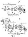
- FIG. 1shows a diagram of a prior art voice communications network 10 including a wireless communications network 12 coupled to a wire line communications network (POTS network) 14 .
- wireless communications network 12includes one or more cellular base stations 16 each having an associated base station antenna 18 and a mobile switching center 20 .
- Mobile switching center 20couples cellular base station 16 to POTS network 14 to allow a wire line call taker 22 , such as a PSAP, to communicate with a mobile unit 24 of wireless communications network 12 .
- mobile unit 24transmits and receives signals that are respectively received and transmitted by cellular base station 16 over two transmission channels 26 .
- These transmission channels 26include a voice channel 27 (which is also known as the call path, the voice call path, the voice call connection, the audio call path, the audio traffic channel, and the traffic channel) for transmitting radio-frequency signals representative of voice, and a control channel 28 (also known as an overhead channel and the non-call path) for transmitting call initiation and control signals.
- voice channel 27which is also known as the call path, the voice call path, the voice call connection, the audio call path, the audio traffic channel, and the traffic channel
- a control channel 28also known as an overhead channel and the non-call path
- transmissions over control channel 28consist of packetized digital data. Protocols for control channel 28 and the type of data that can be carried on control channel 28 are determined by the type of control channel communications protocol in use by wireless communications network. Because each type of wireless network uses its own protocol, control signals must be decoded at cellular base station 16 .
- Wireline and wireless communications systemshave some system latency, typically less than 500 milliseconds (ms), due to propagation and processing of signals traveling in the call path.
- msmilliseconds
- differences in air interface protocols, base stations, handset manufacturers, and transmission distancesmake the system latency variable.
- the present inventionprovides methods for determining a system latency of a voice communication network for signals transmitted between a reference station and a remote unit over an audio call path of the voice communications network.
- the system latencyis then taken into account during synchronization of the remote unit with a reference oscillator of the reference station.
- Measurement of system latencyis accomplished by a signaling sequence including transmitting a reference signal over the audio call path from the reference station to the remote unit, where a reply signal is generated and transmitted back to the reference station over the call path after a preselected reply delay interval.
- the reference signal and the reply signalare transmitted for respective predetermined reference and reply durations, which may be dictated by signal attenuation characteristics of the voice communications network.
- the reply delay intervalbegins upon receipt of the reference signal at the remote unit and must be preselected to allow sufficient time for the remote unit to process the reference signal and generate the reply signal.
- a measurementis made at the reference station to determine a round-trip time difference between transmission of the reference signal and receipt of the reply signal.
- a total latencyis then calculated as the round-trip time difference less the sum of the reference duration, the reply duration, and the reply delay interval.
- a correction intervalis calculated as one-half the total latency, and a synchronization signal representing the correction interval is then transmitted from the reference station over the call path for receipt by the remote unit.
- the remote unitsynchronizes itself with the reference oscillator in response to the synchronization signal. Synchronization may be effectively accomplished in a number of different ways, for example, by storing the synchronization signal at the remote unit and using it later as a parameter for calculating synchronized time, or by adjustment or restarting of the remote oscillator upon receipt of a synchronization mark of the synchronization signal.
- the remote unitis a mobile unit that includes an SPS receiver.
- the remote oscillatoris coupled to or made part of the SPS receiver and is used by the SPS receiver, in conjunction with, SPS satellite signals to determine a location of the remote unit. Synchronization of the remote oscillator may be accomplished by any of the above-described synchronization techniques or by modification, in response to the synchronization signal, of algorithms used by the SPS receiver to calculate the location of the remote unit.
- the reference signal, the reply signal, and the synchronization signalare all audio-frequency signals that are adapted to freely pass through the voice communications network.
- Such audio-frequency signalsare necessary for transmission over a voice call path of an advanced communications network of the type that uses compression protocols and/or spread-spectrum technology to maximize call traffic in a limited radio-frequency bandwidth. Examples of protocols used in advanced communications networks include time-division multiple access (TDMA), code-division multiple access (CDMA), global system for mobile communication (GSM), and others.
- TDMAtime-division multiple access
- CDMAcode-division multiple access
- GSMglobal system for mobile communication
- the reference, reply, and synchronization signalsalso transmit freely through analog wireless networks.
- These audio-frequency signalsare specifically configured to emulate certain characteristics of the human voice such as, for example, frequency, amplitude, and duration. By generating signals that resemble sounds of the human voice, the present invention thereby avoids destruction of the signals by the voice communications network.
- the signalsare audio-frequency signals that include one or more audio tones, multi-frequency tones, or substantially Gaussian pulses generated by a multi-frequency controller.
- the Gaussian pulsesare characterized by a 3 ⁇ (standard deviation ⁇ 3) of between about 0.3 ms and 1 ms, and an amplitude of between ⁇ 4 dBm and ⁇ 10 dBm to avoid destructive attenuation by the voice communications network.
- Single or multi-frequency toneshave a duration of between about 5 ms and 50 ms and a frequency in the range of about 300 to 3000 Hz.
- the time of receipt of the tones or pulses (of a particular signal)may be averaged to improve accuracy of latency measurements and synchronization.
- the signalsmay also comprise a pulse train created by concatenating a plurality of tones or pulses spaced at regular and irregular intervals. Irregular spacing of tones or pulses facilitates accurate correlation of the reply signal to the reference signal at the reference station for calculation of the total round-trip time difference. Use of these techniques allows synchronization of the remote unit to within +/ ⁇ 500 ⁇ sec of the reference oscillator. In SPS-enabled remote units, use of the method of the present invention significantly reduces the time it takes the SPS receiver to attain SPS lock.
- the signaling sequenceis initiated by the remote unit, which generates and transmits the reference pulse, the receipt of which prompts the reference station to reply with a reply pulse after a reply delay interval. Latency calculations may then be performed at the remote unit. Synchronization of the remote unit still requires the remote unit to receive a synchronization signal transmitted by the reference station upon a time mark output of the reference oscillator.
- the present inventionpresents particularly significant advantages in the context of a cellular telephone network in which the remote unit comprises a wireless communications device such as a cellular telephone.
- the remote unitcomprises a wireless communications device such as a cellular telephone.
- the present inventionrequires no special equipment or software to be installed at a base station site of the wireless network for handling the reference, reply, and synchronization signals.
- POTSwireless and wire line
- “In-band” signals in the voice call pathcan be received at any point in the wireless or wire line networks, for to example at a location services controller or PSAP, which may also serve as a reference station.
- the present inventionalso provides advantages over prior-art wireless modem devices, which fully occupy the voice call path during data transmission by switching the wireless communications device to a data mode. By keeping the voice call path available to the wireless telephone user during latency measurement, synchronization, and location data transfer, the present invention facilitates substantially concurrent verbal communication between the wireless user and a call taker.
- FIG. 1is a diagram of a prior-art wireless communications network showing components of a wireless communications network and their connection to a wire line communications network;
- FIG. 2is a diagram of a mobile unit including a SPS receiver in communication with a call taker over a wireless communications network for implementing a synchronization protocol in accordance with the present invention
- FIG. 3is a diagram of a signal transmission sequence in accordance with the present invention.
- FIG. 4is a timing diagram showing the timing and elements of a reference signal, a reply signal, and a synchronization signal of the signal transmission sequence of FIG. 3;
- FIG. 5Ais a diagram of a first alternative embodiment audio-frequency signal, comprising first and second reference tones
- FIG. 5Bis a diagram of a second alternative embodiment audio-frequency signal, comprising a Gaussian pulse
- FIG. 5Cis a diagram of a third alternative embodiment audio-frequency signal comprising a reference pulse train, overlaid with an observed reply pulse train;
- FIG. 6is a schematic diagram of a mobile unit including a SPS receiver and a multi-frequency controller implementing the present invention.
- FIG. 2shows a diagram of a voice communications network 30 including an SPS-enabled mobile unit 40 for implementing a first preferred embodiment of the present invention.
- voice communications network 30includes a wireless communications network 44 coupled to a public switched telephone network or (“POTS”) 48 .
- Wireless communications network 44includes a base station 52 for transmitting radio frequency signals 56 to mobile unit 40 and for receiving radio frequency signals 56 from mobile unit 40 .
- Radio frequency signals 56include a voice channel signal 58 for transmitting audio, and a control channel signal 60 for transmitting control commands and digital data.
- a mobile switching center 64couples wireless communication network 44 to POTS 48 .
- Mobile unit 40is preferably a cellular telephone handset, but may be any type of wireless communications device capable of transmitting over voice channel 58 .
- Mobile unit 40includes a local oscillator (also referred to as a “mobile oscillator” or a “remote oscillator”) and an SPS receiver 66 for receiving SPS signals 70 that are broadcast by SPS satellites 72 in earth orbit and for calculating a location of the mobile unit based upon SPS signals 70 .
- SPS receiver 66achieves “lock” with SPS signals 70 to synchronize the local oscillator to within +/ ⁇ 10 microseconds ( ⁇ sec).
- ⁇ secmicroseconds
- resynchronization of the SPS oscillatormay be initiated automatically by mobile unit 40 , as necessary, or may occur during the next telephone call received or made by mobile unit 40 .
- the local oscillatormay be synchronized with a reference oscillator positioned at a known terrestrial location.
- This type of resynchronization procedureis known as “seeding” SPS receiver 66 because it results in synchronization to a wider tolerance than occurs during SPS lock.
- a seed processor 80communicates with a reference SPS receiver 82 and the reference oscillator, which may be integrated with SPS receiver 82 .
- Seed processor 80may be coupled to wireless communications switch 64 or a call taking device 86 of POTS 48 , or both. Once an audio call path has been established between seed processor 80 and mobile unit 40 , seed processor 80 initiates a signaling sequence 100 (FIG. 3) to determine system latency and for synchronization of the local oscillator with the reference oscillator.
- FIG. 3is a diagram of the signaling sequence 100 for measuring system latency.
- a reference station 102such as a location services controller (LSC) 104 transmits a reference signal over voice channel 58 (FIG. 2 ).
- a remote unit 108such as a cellular telephone handset (HS) 110 receives reference signal 106 after a reference latency t 2 .
- Remote unit 108then responds to receipt of reference signal 106 by transmitting a reply signal 112 , which is received at reference station 102 after a reply latency t 2 .
- Reference latency t 1 and reply latency t 2include both signal propagation time and time for processing the respective reference and reply signals 106 , 112 at reference station 102 and remote unit 108 .
- the elapsed time between the transmission of reference signal 106 and the receipt of reply signal 112is measured at reference station 102 to determine a round-trip delay t RT . If the reference latency t 1 and the reply latency t 2 are equal, the system is said to be symmetric. For purposes of illustration, asymmetry is exaggerated in FIG. 3 . However, empirical measurements on CDMA, TDMA, GSM, and analog wireless phone systems, confirm that POTS network 48 in combination with wireless communications network 44 (FIG. 2) is symmetric (and substantially time-invariant during each call session) to within tolerances acceptable for the purpose of in-band signaling for time synchronization within +/ ⁇ 500 ⁇ sec. Because wireless and POTS communications networks are substantially symmetric, a one-way latency can be estimated as one-half the round-trip delay, or 1 ⁇ 2t RT .
- FIG. 4is a timing diagram showing the timing and elements of signaling sequence 100 .
- the upper section of the timing diagramshows signals at reference station 102
- the lower sectionshows signals at remote unit 108 .
- Transmitted signalsare shown in solid lines, while received signals are shown in dashed lines.
- Signaling sequence 100is shown in FIG. 4 as being initiated by reference station 102 , but may be initiated in an alternative embodiment (not shown) at remote unit 108 .
- reference station 102transmits reference signal 106 having a reference duration t ref .
- reference signal 106is transmitted by reference station 102 upon occurrence of a periodic time mark 120 of the reference oscillator having a period P.
- Reference signal 106is received at remote unit 108 after reference latency t 1 .
- remote unit 108Upon receipt of reference signal 106 , remote unit 108 generates a reply signal 112 and transmits reply signal 112 after a preselected reply delay interval t det .
- Reply signal 112has a reply duration t rp and is received a reference station 102 after reply latency t 2 .
- a measurement of round trip delay t RTis made at reference station 102 .
- a total latency T Lis then calculated as:
- T Lt RT ⁇ ( t ref +t det +t rp )
- a synchronization signal 124 representative of correction interval T cis transmitted from reference station 102 .
- Synchronization signal 124is transmitted upon the next time mark 120 , and correction interval T c is transmitted as data to remote unit 108 , either as part of synchronization signal 124 or as part of a separate data signal (not shown).
- synchronization signal 124 ′is transmitted at a correction time 126 in advance of a future time mark 120 ′ by an amount equal to correction interval T c .
- Remote unit 108then utilizes correction interval T c and/or a time of receipt 127 of synchronization signal 124 ′ to synchronize with the reference oscillator.
- synchronizationcan be accomplished in a variety of ways, based upon receipt at remote unit 108 of one or more signals representing correction interval T c and a time mark 120 of the reference oscillator.
- synchronization signal 124may be generated by forming a delayed time mark that is delayed by an amount equal to period P minus the correction interval T c .
- Voice communication networks and, particularly, digital cellular telephone networksuse signal compression, spread-spectrum signal transmission, and other signal manipulation protocols to maximize call traffic in the signal transmission medium. These signal-processing protocols tend to remove signals in the call path that do not resemble human voice.
- reference signal 106 , reply signal 112 , and synchronization signal 124are all generated as audio-frequency signals in the audio call path.
- audio-frequency signalsare converted numerous times between analog signal form, digital signal form, and radio frequency signal form during encoding, transmission, and decoding, as normally occurs in the audio call path of a wireless telephone network.
- Audio-frequency signalsas used herein describes any signal representative of audio as it travels in the call path, regardless of its form.
- Reference signal 106 , reply signal 112 , and synchronization signal 124are generated to have characteristics that have been found empirically to pass through voice communications network 30 .
- FIGS. 5A, 5 B, and 5 Cshow respective first, second, and third alternative embodiments of an audio-frequency signal 128 a , 128 b , and 128 c that may be used for reference signal 106 , reply signal 112 , and synchronization signal 124 .
- a first alternative embodiment audio-frequency signal 128 aincludes a first audio-frequency tone 130 and a second audio-frequency tone 132 spaced apart in time by a reference pause 134 .
- First and second audio-frequency tones 130 , 132are each characterized by a frequency of between 300 Hz and 3000 Hz, a predetermined duration of between 5 ms and 50 ms, and an amplitude of between ⁇ 4 dBm and ⁇ 10 dBm.
- Reference pause 134is characterized by a preselected duration, which for convenience may be the same as the duration of first and second audio-frequency tones 130 , 132 , but may be selected to be shorter or longer.
- the use of multiple tonesallows remote unit 108 and reference station 102 to average first and second audio-frequency tones 130 , 132 as they are received and thereby more accurately determine the time at which audio-frequency signal 128 a is received.
- FIG. 5Cshows a third alternative embodiment of reference signal 106 ′, overlaid with a corresponding reply signal 112 ′.
- a third alternative embodiment audio-frequency signal 128 ccomprises a reference pulse train 140 including eight substantially Gaussian reference pulses 144 spaced at predefined intervals a, b, c, d, e, f, and g.
- reply signal 112 ′shown in FIG.
- 5C as received at reference station 102comprises a reply pulse train including eight substantially Gaussian reply pulses 148 spaced substantially identical to reference pulses 144 .
- Intervals a-gare irregular to enhance correlation at reference station 102 when determining round trip delay t RT .
- irregular intervals a-gcorrelation can be performed mathematically, even if not all of the Gaussian pulses 144 , 148 are received.
- the widths and intervals of reference pulses 144may be selected so that only one of the reply pulses 148 need be received to correlate the pulse trains and determine total round trip delay t RT , although less accurately than if more pulses are received.
- third alternative embodiment audio-frequency signal 128 ccomprises an analog filtered pulse train modulated onto a voice-frequency carrier signal, with pulses 11.4 ms long with 3 dB bandwidth of 400 Hz and roll-off of 1.0.
- a total duration t PT of pulse train 140is between about 143 ms and 189 ms.
- the voice-frequency carrier signalcan be any signal in the voice frequency spectrum (300 Hz to 3000 Hz), but is preferably an 1800 Hz signal.
- FIG. 6shows a schematic diagram of selected signal processing components of mobile unit 40 .
- mobile unit 40includes an audio bridge 200 connected to a multi-frequency controller 204 and a modem transceiver 208 .
- Multi-frequency controller 204 and modem transceiver 208are connected to an interface processor 212 via, for example, an RS- 232 connection 214 .
- Interface processor 212is connected to an SPS receiver 216 that includes an SPS antenna 220 .
- Both multi-frequency controller 204 and modem transceiver 208actively listen to the call path during signaling sequence 100 .
- multi-frequency controller 204the functions of multi-frequency controller 204 , modem transceiver 208 , interface processor 212 , and SPS receiver 216 are integrated onto existing components of mobile unit 40 , such as a CODEC, a digital signal processor (DSP), and an ARM microprocessor found in known cellular telephones.
- multi-frequency controller 204may be a personal computer including a sound card and running MATLAB software available from Mathworks, Inc., Natick, Mass., USA, or any other commercially available multi-frequency controller.
- interface processor 212 and multi-frequency controller 204ideally operate so that the total root mean square error of the entirety of signaling sequence 100 is less than 0.1 ms.
- Reference station 102includes signal processing components that are similar to those of mobile unit, including a reference multi-frequency controller, a reference modem transceiver, and a reference interface processor.
Landscapes
- Engineering & Computer Science (AREA)
- Computer Networks & Wireless Communication (AREA)
- Signal Processing (AREA)
- Mobile Radio Communication Systems (AREA)
- Synchronisation In Digital Transmission Systems (AREA)
Abstract
Description

Claims (33)
Priority Applications (2)
| Application Number | Priority Date | Filing Date | Title |
|---|---|---|---|
| US09/484,942US6771629B1 (en) | 1999-01-15 | 2000-01-18 | In-band signaling for synchronization in a voice communications network |
| US09/888,085US7164662B2 (en) | 1997-05-19 | 2001-06-22 | Network delay identification method and apparatus |
Applications Claiming Priority (2)
| Application Number | Priority Date | Filing Date | Title |
|---|---|---|---|
| US11609399P | 1999-01-15 | 1999-01-15 | |
| US09/484,942US6771629B1 (en) | 1999-01-15 | 2000-01-18 | In-band signaling for synchronization in a voice communications network |
Related Parent Applications (2)
| Application Number | Title | Priority Date | Filing Date |
|---|---|---|---|
| US09230079Continuation-In-Part | 1998-05-19 | ||
| PCT/US1998/010317Continuation-In-PartWO1998053573A2 (en) | 1997-05-19 | 1998-05-19 | System and method to communicate time stamped, 3-axis geo-position data within telecommunication networks |
Related Child Applications (2)
| Application Number | Title | Priority Date | Filing Date |
|---|---|---|---|
| US09/230,079A-371-Of-InternationalUS6144336A (en) | 1997-05-19 | 1998-05-19 | System and method to communicate time stamped, 3-axis geo-position data within telecommunication networks |
| US09/531,367Continuation-In-PartUS6690681B1 (en) | 1997-05-19 | 2000-03-21 | In-band signaling for data communications over digital wireless telecommunications network |
Publications (1)
| Publication Number | Publication Date |
|---|---|
| US6771629B1true US6771629B1 (en) | 2004-08-03 |
Family
ID=32775427
Family Applications (1)
| Application Number | Title | Priority Date | Filing Date |
|---|---|---|---|
| US09/484,942Expired - Fee RelatedUS6771629B1 (en) | 1997-05-19 | 2000-01-18 | In-band signaling for synchronization in a voice communications network |
Country Status (1)
| Country | Link |
|---|---|
| US (1) | US6771629B1 (en) |
Cited By (58)
| Publication number | Priority date | Publication date | Assignee | Title |
|---|---|---|---|---|
| US20030122705A1 (en)* | 2001-12-31 | 2003-07-03 | Paul Marko | Method and apparatus for determining location in a satellite communication system |
| US6903683B1 (en)* | 2003-11-19 | 2005-06-07 | Nortel Networks Limited | Method for delivering assistance data in an unsynchronized wireless network |
| US20050280576A1 (en)* | 2003-12-17 | 2005-12-22 | Yaron Shemesh | Subscriber unit, a cellular communication system and a method for determining a location therefor |
| US20050285783A1 (en)* | 2004-06-29 | 2005-12-29 | Neil Harper | Global positioning system signal acquisition assistance |
| US20060089959A1 (en)* | 2004-10-26 | 2006-04-27 | Harman Becker Automotive Systems - Wavemakers, Inc. | Periodic signal enhancement system |
| US20060095256A1 (en)* | 2004-10-26 | 2006-05-04 | Rajeev Nongpiur | Adaptive filter pitch extraction |
| US20060098809A1 (en)* | 2004-10-26 | 2006-05-11 | Harman Becker Automotive Systems - Wavemakers, Inc. | Periodic signal enhancement system |
| US20060136199A1 (en)* | 2004-10-26 | 2006-06-22 | Haman Becker Automotive Systems - Wavemakers, Inc. | Advanced periodic signal enhancement |
| US20060262875A1 (en)* | 2005-05-17 | 2006-11-23 | Madhavan Sethu K | Data transmission method with phase shift error correction |
| US20070025281A1 (en)* | 2005-07-28 | 2007-02-01 | Mcfarland Sheila J | Network dependent signal processing |
| US20070092024A1 (en)* | 2005-10-24 | 2007-04-26 | General Motors Corporation | Method for data communication via a voice channel of a wireless communication network |
| US20070136055A1 (en)* | 2005-12-13 | 2007-06-14 | Hetherington Phillip A | System for data communication over voice band robust to noise |
| US20070190950A1 (en)* | 2006-02-15 | 2007-08-16 | General Motors Corporation | Method of configuring voice and data communication over a voice channel |
| US7286522B2 (en) | 1998-05-19 | 2007-10-23 | Airbiquity, Inc. | Synchronizer for use with improved in-band signaling for data communications over digital wireless telecommunications networks |
| US20070258398A1 (en)* | 2005-10-24 | 2007-11-08 | General Motors Corporation | Method for data communication via a voice channel of a wireless communication network |
| US20080004868A1 (en)* | 2004-10-26 | 2008-01-03 | Rajeev Nongpiur | Sub-band periodic signal enhancement system |
| US7317696B2 (en) | 1997-05-19 | 2008-01-08 | Airbiquity Inc. | Method for in-band signaling of data over digital wireless telecommunications networks |
| US20080231557A1 (en)* | 2007-03-20 | 2008-09-25 | Leadis Technology, Inc. | Emission control in aged active matrix oled display using voltage ratio or current ratio |
| US20080240163A1 (en)* | 2007-04-02 | 2008-10-02 | Texas Instruments Incorporated | System and method for maintaining transmission synchrony |
| US20080247484A1 (en)* | 2007-04-03 | 2008-10-09 | General Motors Corporation | Method for data communication via a voice channel of a wireless communication network using continuous signal modulation |
| US20080255828A1 (en)* | 2005-10-24 | 2008-10-16 | General Motors Corporation | Data communication via a voice channel of a wireless communication network using discontinuities |
| US20080273644A1 (en)* | 2007-05-03 | 2008-11-06 | Elizabeth Chesnutt | Synchronization and segment type detection method for data transmission via an audio communication system |
| US20090047904A1 (en)* | 2001-04-24 | 2009-02-19 | Medius, Inc. | Method and apparatus for dynamic configuration of multiprocessor system |
| US20090112579A1 (en)* | 2007-10-24 | 2009-04-30 | Qnx Software Systems (Wavemakers), Inc. | Speech enhancement through partial speech reconstruction |
| US20090112584A1 (en)* | 2007-10-24 | 2009-04-30 | Xueman Li | Dynamic noise reduction |
| US20090147806A1 (en)* | 2007-11-02 | 2009-06-11 | Nortel Networks Limited | Synchronization of network nodes |
| US20090235044A1 (en)* | 2008-02-04 | 2009-09-17 | Michael Kisel | Media processing system having resource partitioning |
| US20090238343A1 (en)* | 2008-03-19 | 2009-09-24 | Gerhard Geldenbott | End-to-end logic tracing of complex call flows in a distributed call system |
| US20090287481A1 (en)* | 2005-09-02 | 2009-11-19 | Shreyas Paranjpe | Speech enhancement system |
| US20090292536A1 (en)* | 2007-10-24 | 2009-11-26 | Hetherington Phillip A | Speech enhancement with minimum gating |
| US20100041416A1 (en)* | 2006-10-18 | 2010-02-18 | Yoshihisa Manzen | Mobile communication terminal with gps function, positioning system, operation control method, and program |
| US7680652B2 (en) | 2004-10-26 | 2010-03-16 | Qnx Software Systems (Wavemakers), Inc. | Periodic signal enhancement system |
| US7733853B2 (en) | 2005-01-31 | 2010-06-08 | Airbiquity, Inc. | Voice channel control of wireless packet data communications |
| US7848763B2 (en) | 2001-11-01 | 2010-12-07 | Airbiquity Inc. | Method for pulling geographic location data from a remote wireless telecommunications mobile unit |
| US7924934B2 (en) | 2006-04-07 | 2011-04-12 | Airbiquity, Inc. | Time diversity voice channel data communications |
| US20110156896A1 (en)* | 1999-02-01 | 2011-06-30 | Hoffberg Steven M | Internet appliance system and method |
| US7979095B2 (en) | 2007-10-20 | 2011-07-12 | Airbiquity, Inc. | Wireless in-band signaling with in-vehicle systems |
| US7983310B2 (en) | 2008-09-15 | 2011-07-19 | Airbiquity Inc. | Methods for in-band signaling through enhanced variable-rate codecs |
| US8006119B1 (en) | 2002-04-24 | 2011-08-23 | Eagle Harbor Holdings | Application management system |
| US8001860B1 (en) | 2004-11-09 | 2011-08-23 | Eagle Harbor Holdings LLC | Method and apparatus for the alignment of multi-aperture systems |
| US8036600B2 (en) | 2009-04-27 | 2011-10-11 | Airbiquity, Inc. | Using a bluetooth capable mobile phone to access a remote network |
| US20120063355A1 (en)* | 2010-09-14 | 2012-03-15 | Research In Motion Limited | Apparatus, and associated method, for providing support-call data pursuant to a wireless device support call |
| US8249865B2 (en) | 2009-11-23 | 2012-08-21 | Airbiquity Inc. | Adaptive data transmission for a digital in-band modem operating over a voice channel |
| US8417490B1 (en) | 2009-05-11 | 2013-04-09 | Eagle Harbor Holdings, Llc | System and method for the configuration of an automotive vehicle with modeled sensors |
| US8418039B2 (en) | 2009-08-03 | 2013-04-09 | Airbiquity Inc. | Efficient error correction scheme for data transmission in a wireless in-band signaling system |
| US8543390B2 (en) | 2004-10-26 | 2013-09-24 | Qnx Software Systems Limited | Multi-channel periodic signal enhancement system |
| US8594138B2 (en) | 2008-09-15 | 2013-11-26 | Airbiquity Inc. | Methods for in-band signaling through enhanced variable-rate codecs |
| US8694310B2 (en) | 2007-09-17 | 2014-04-08 | Qnx Software Systems Limited | Remote control server protocol system |
| US8850154B2 (en) | 2007-09-11 | 2014-09-30 | 2236008 Ontario Inc. | Processing system having memory partitioning |
| US8848825B2 (en) | 2011-09-22 | 2014-09-30 | Airbiquity Inc. | Echo cancellation in wireless inband signaling modem |
| US8886392B1 (en) | 2011-12-21 | 2014-11-11 | Intellectual Ventures Fund 79 Llc | Methods, devices, and mediums associated with managing vehicle maintenance activities |
| US8892495B2 (en) | 1991-12-23 | 2014-11-18 | Blanding Hovenweep, Llc | Adaptive pattern recognition based controller apparatus and method and human-interface therefore |
| US8904400B2 (en) | 2007-09-11 | 2014-12-02 | 2236008 Ontario Inc. | Processing system having a partitioning component for resource partitioning |
| US9358924B1 (en) | 2009-05-08 | 2016-06-07 | Eagle Harbor Holdings, Llc | System and method for modeling advanced automotive safety systems |
| US20180352434A1 (en)* | 2017-06-05 | 2018-12-06 | Renesas Electronics Corporation | Wireless communication system, beacon device, information processing terminal, and beacon device authentication method |
| US10298735B2 (en) | 2001-04-24 | 2019-05-21 | Northwater Intellectual Property Fund L.P. 2 | Method and apparatus for dynamic configuration of a multiprocessor health data system |
| US10361802B1 (en) | 1999-02-01 | 2019-07-23 | Blanding Hovenweep, Llc | Adaptive pattern recognition based control system and method |
| US11304163B2 (en)* | 2020-03-19 | 2022-04-12 | Kabushiki Kaisha Toshiba | Wireless communication apparatus and wireless communication system |
Citations (29)
| Publication number | Priority date | Publication date | Assignee | Title |
|---|---|---|---|---|
| US4218654A (en) | 1978-04-28 | 1980-08-19 | Kokusai Denshin Denwa Kabushiki Kaisha | Space diversity system in TDMA communication system |
| US4310722A (en) | 1978-11-09 | 1982-01-12 | Bell Telephone Laboratories, Incorporated | Mobile radiotelephone station two-way ranging system |
| US4368987A (en) | 1980-06-25 | 1983-01-18 | The United States Of America As Represented By The Secretary Of The Navy | Conjugate-phase, remote-clock synchronizer |
| US4494211A (en) | 1982-11-24 | 1985-01-15 | The United States Of America As Represented By The Secretary Of The Navy | Balanced system for ranging and synchronization between satellite pairs |
| US4607257A (en)* | 1981-12-25 | 1986-08-19 | Nippon Electric Co. Ltd. | Remote calibrating system for satellite time |
| US5014344A (en) | 1990-03-19 | 1991-05-07 | Motorola, Inc. | Method for synchronizing the transmissions in a simulcast transmission system |
| US5245634A (en) | 1992-03-23 | 1993-09-14 | Motorola, Inc. | Base-site synchronization in a communication system |
| US5509035A (en) | 1993-04-14 | 1996-04-16 | Qualcomm Incorporated | Mobile station operating in an analog mode and for subsequent handoff to another system |
| US5510797A (en)* | 1993-04-15 | 1996-04-23 | Trimble Navigation Limited | Provision of SPS timing signals |
| US5663734A (en) | 1995-10-09 | 1997-09-02 | Precision Tracking, Inc. | GPS receiver and method for processing GPS signals |
| US5812087A (en) | 1997-02-03 | 1998-09-22 | Snaptrack, Inc. | Method and apparatus for satellite positioning system based time measurement |
| US5825327A (en) | 1996-03-08 | 1998-10-20 | Snaptrack, Inc. | GPS receivers and garments containing GPS receivers and methods for using these GPS receivers |
| US5831574A (en) | 1996-03-08 | 1998-11-03 | Snaptrack, Inc. | Method and apparatus for determining the location of an object which may have an obstructed view of the sky |
| US5841396A (en) | 1996-03-08 | 1998-11-24 | Snaptrack, Inc. | GPS receiver utilizing a communication link |
| WO1998059257A1 (en) | 1997-06-24 | 1998-12-30 | Snaptrack, Inc. | Highly parallel gps correlator system and method |
| EP0896442A1 (en) | 1996-12-26 | 1999-02-10 | Ntt Mobile Communications Network Inc. | Frame transmitter-receiver |
| US5884214A (en) | 1996-09-06 | 1999-03-16 | Snaptrack, Inc. | GPS receiver and method for processing GPS signals |
| JPH11109062A (en) | 1997-09-30 | 1999-04-23 | Nec Corp | Time synchronous system |
| US5912886A (en)* | 1996-02-09 | 1999-06-15 | Nec Corporation | Digital mobile communication system capable of establishing mutual synchronization among a plurality of radio base stations |
| US5917449A (en) | 1995-06-07 | 1999-06-29 | Sanconix Inc. | Enhanced position calculation |
| WO1999036795A1 (en) | 1998-01-20 | 1999-07-22 | Snaptrack, Inc. | Reducing cross-interference in a combined gps receiver and communication system |
| US5930722A (en) | 1995-03-07 | 1999-07-27 | Hyundai Electronics Industries Co. Ltd. | Digital mobile communication system and timing design method between various subsystems |
| US5945944A (en) | 1996-03-08 | 1999-08-31 | Snaptrack, Inc. | Method and apparatus for determining time for GPS receivers |
| WO1999056143A1 (en) | 1998-04-28 | 1999-11-04 | Snaptrack, Inc. | Distributed satellite position system processing and application network |
| WO1999056144A1 (en) | 1998-04-28 | 1999-11-04 | Snaptrack, Inc. | Method and apparatus for providing location-based information via a computer network |
| US5999124A (en) | 1998-04-22 | 1999-12-07 | Snaptrack, Inc, | Satellite positioning system augmentation with wireless communication signals |
| US6002363A (en) | 1996-03-08 | 1999-12-14 | Snaptrack, Inc. | Combined GPS positioning system and communications system utilizing shared circuitry |
| US6031489A (en) | 1997-02-01 | 2000-02-29 | Ico Services Ltd. | User terminal positioning system and method employing external signals |
| US6144336A (en)* | 1997-05-19 | 2000-11-07 | Integrated Data Communications, Inc. | System and method to communicate time stamped, 3-axis geo-position data within telecommunication networks |
- 2000
- 2000-01-18USUS09/484,942patent/US6771629B1/ennot_activeExpired - Fee Related
Patent Citations (31)
| Publication number | Priority date | Publication date | Assignee | Title |
|---|---|---|---|---|
| US4218654A (en) | 1978-04-28 | 1980-08-19 | Kokusai Denshin Denwa Kabushiki Kaisha | Space diversity system in TDMA communication system |
| US4310722A (en) | 1978-11-09 | 1982-01-12 | Bell Telephone Laboratories, Incorporated | Mobile radiotelephone station two-way ranging system |
| US4368987A (en) | 1980-06-25 | 1983-01-18 | The United States Of America As Represented By The Secretary Of The Navy | Conjugate-phase, remote-clock synchronizer |
| US4607257A (en)* | 1981-12-25 | 1986-08-19 | Nippon Electric Co. Ltd. | Remote calibrating system for satellite time |
| US4494211A (en) | 1982-11-24 | 1985-01-15 | The United States Of America As Represented By The Secretary Of The Navy | Balanced system for ranging and synchronization between satellite pairs |
| US5014344A (en) | 1990-03-19 | 1991-05-07 | Motorola, Inc. | Method for synchronizing the transmissions in a simulcast transmission system |
| US5245634A (en) | 1992-03-23 | 1993-09-14 | Motorola, Inc. | Base-site synchronization in a communication system |
| US5509035A (en) | 1993-04-14 | 1996-04-16 | Qualcomm Incorporated | Mobile station operating in an analog mode and for subsequent handoff to another system |
| US5510797A (en)* | 1993-04-15 | 1996-04-23 | Trimble Navigation Limited | Provision of SPS timing signals |
| US5930722A (en) | 1995-03-07 | 1999-07-27 | Hyundai Electronics Industries Co. Ltd. | Digital mobile communication system and timing design method between various subsystems |
| US5917449A (en) | 1995-06-07 | 1999-06-29 | Sanconix Inc. | Enhanced position calculation |
| US5781156A (en) | 1995-10-09 | 1998-07-14 | Snaptrack, Inc. | GPS receiver and method for processing GPS signals |
| US5874914A (en) | 1995-10-09 | 1999-02-23 | Snaptrack, Inc. | GPS receiver utilizing a communication link |
| US5663734A (en) | 1995-10-09 | 1997-09-02 | Precision Tracking, Inc. | GPS receiver and method for processing GPS signals |
| US5912886A (en)* | 1996-02-09 | 1999-06-15 | Nec Corporation | Digital mobile communication system capable of establishing mutual synchronization among a plurality of radio base stations |
| US5825327A (en) | 1996-03-08 | 1998-10-20 | Snaptrack, Inc. | GPS receivers and garments containing GPS receivers and methods for using these GPS receivers |
| US5831574A (en) | 1996-03-08 | 1998-11-03 | Snaptrack, Inc. | Method and apparatus for determining the location of an object which may have an obstructed view of the sky |
| US5841396A (en) | 1996-03-08 | 1998-11-24 | Snaptrack, Inc. | GPS receiver utilizing a communication link |
| US6002363A (en) | 1996-03-08 | 1999-12-14 | Snaptrack, Inc. | Combined GPS positioning system and communications system utilizing shared circuitry |
| US5945944A (en) | 1996-03-08 | 1999-08-31 | Snaptrack, Inc. | Method and apparatus for determining time for GPS receivers |
| US5884214A (en) | 1996-09-06 | 1999-03-16 | Snaptrack, Inc. | GPS receiver and method for processing GPS signals |
| EP0896442A1 (en) | 1996-12-26 | 1999-02-10 | Ntt Mobile Communications Network Inc. | Frame transmitter-receiver |
| US6031489A (en) | 1997-02-01 | 2000-02-29 | Ico Services Ltd. | User terminal positioning system and method employing external signals |
| US5812087A (en) | 1997-02-03 | 1998-09-22 | Snaptrack, Inc. | Method and apparatus for satellite positioning system based time measurement |
| US6144336A (en)* | 1997-05-19 | 2000-11-07 | Integrated Data Communications, Inc. | System and method to communicate time stamped, 3-axis geo-position data within telecommunication networks |
| WO1998059257A1 (en) | 1997-06-24 | 1998-12-30 | Snaptrack, Inc. | Highly parallel gps correlator system and method |
| JPH11109062A (en) | 1997-09-30 | 1999-04-23 | Nec Corp | Time synchronous system |
| WO1999036795A1 (en) | 1998-01-20 | 1999-07-22 | Snaptrack, Inc. | Reducing cross-interference in a combined gps receiver and communication system |
| US5999124A (en) | 1998-04-22 | 1999-12-07 | Snaptrack, Inc, | Satellite positioning system augmentation with wireless communication signals |
| WO1999056143A1 (en) | 1998-04-28 | 1999-11-04 | Snaptrack, Inc. | Distributed satellite position system processing and application network |
| WO1999056144A1 (en) | 1998-04-28 | 1999-11-04 | Snaptrack, Inc. | Method and apparatus for providing location-based information via a computer network |
Non-Patent Citations (4)
| Title |
|---|
| International Search Report for International Application No. PCT/US01/19845, Nov. 22, 2001. |
| Jain et al, Potential Networking Applications of Global Positioning Systems (GPS), downloadable at http://www.cis.ohio-state.edu/~jain/papers/gps.htm, pp. 1-40, Apr. 1996.** |
| Jain et al, Potential Networking Applications of Global Positioning Systems (GPS), downloadable at http://www.cis.ohio-state.edu/˜jain/papers/gps.htm, pp. 1-40, Apr. 1996.* |
| PCT International Search Report, dated May 23, 2000 for International Application No. PCT/US00/01157. |
Cited By (129)
| Publication number | Priority date | Publication date | Assignee | Title |
|---|---|---|---|---|
| US8892495B2 (en) | 1991-12-23 | 2014-11-18 | Blanding Hovenweep, Llc | Adaptive pattern recognition based controller apparatus and method and human-interface therefore |
| US7747281B2 (en) | 1997-05-19 | 2010-06-29 | Airbiquity Inc. | Method for in-band signaling of data over digital wireless telecommunications networks |
| US7317696B2 (en) | 1997-05-19 | 2008-01-08 | Airbiquity Inc. | Method for in-band signaling of data over digital wireless telecommunications networks |
| US7286522B2 (en) | 1998-05-19 | 2007-10-23 | Airbiquity, Inc. | Synchronizer for use with improved in-band signaling for data communications over digital wireless telecommunications networks |
| US8068792B2 (en) | 1998-05-19 | 2011-11-29 | Airbiquity Inc. | In-band signaling for data communications over digital wireless telecommunications networks |
| US20110156896A1 (en)* | 1999-02-01 | 2011-06-30 | Hoffberg Steven M | Internet appliance system and method |
| US8369967B2 (en) | 1999-02-01 | 2013-02-05 | Hoffberg Steven M | Alarm system controller and a method for controlling an alarm system |
| US10361802B1 (en) | 1999-02-01 | 2019-07-23 | Blanding Hovenweep, Llc | Adaptive pattern recognition based control system and method |
| US9535563B2 (en) | 1999-02-01 | 2017-01-03 | Blanding Hovenweep, Llc | Internet appliance system and method |
| US20090047904A1 (en)* | 2001-04-24 | 2009-02-19 | Medius, Inc. | Method and apparatus for dynamic configuration of multiprocessor system |
| US8630196B2 (en) | 2001-04-24 | 2014-01-14 | Eagle Harbor Holdings, Llc | Multiprocessor system and method for conducting transactions from a vehicle |
| US9697015B2 (en) | 2001-04-24 | 2017-07-04 | Eagle Harbor Holdings, Llc | Vehicle audio application management system using logic circuitry |
| US9652257B2 (en) | 2001-04-24 | 2017-05-16 | Eagle Harbor Holdings, Llc | Vehicle safety system |
| US9645832B2 (en) | 2001-04-24 | 2017-05-09 | Dan A. Preston | Dynamic configuration of a home multiprocessor system |
| US8027268B2 (en) | 2001-04-24 | 2011-09-27 | Eagle Harbor Holdings, Llc | Method and apparatus for dynamic configuration of multiprocessor system |
| US9811354B2 (en) | 2001-04-24 | 2017-11-07 | Eagle Harbor Holdings, Llc | Home audio system for operating different types of audio sources |
| US10102013B2 (en) | 2001-04-24 | 2018-10-16 | Northwater Intellectual Property Fund, L.P. 2 | Method and system for dynamic configuration of multiprocessor system |
| US9348637B2 (en) | 2001-04-24 | 2016-05-24 | Eagle Harbor Holdings, Llc | Dynamic configuration of a home multiprocessor system |
| US10298735B2 (en) | 2001-04-24 | 2019-05-21 | Northwater Intellectual Property Fund L.P. 2 | Method and apparatus for dynamic configuration of a multiprocessor health data system |
| US9336043B2 (en) | 2001-04-24 | 2016-05-10 | Dan Alan Preston | Method and apparatus for a task priority processing system |
| US9292334B2 (en) | 2001-04-24 | 2016-03-22 | Eagle Harbor Holdings, Llc | Method and apparatus for dynamic configuration of multiprocessor system |
| US8958315B2 (en) | 2001-04-24 | 2015-02-17 | Eagle Harbor Holdings, Llc | Method and apparatus for dynamic configuration of multiprocessor system |
| US8953816B1 (en) | 2001-04-24 | 2015-02-10 | Eagle Harbor Holdings LLC | Method and apparatus to dynamically configure a vehicle audio system |
| US10387166B2 (en) | 2001-04-24 | 2019-08-20 | Northwater Intellectual Property Fund L.P. 2 | Dynamic configuration of a multiprocessor system |
| US8045729B2 (en) | 2001-04-24 | 2011-10-25 | Eagle Harbor Holdings, Llc | Audio system with application management system for operating different types of audio sources |
| US8762610B2 (en) | 2001-04-24 | 2014-06-24 | Eagle Harbor Holdings, Llc | Processing method for reprioritizing software application tasks |
| US8751712B2 (en) | 2001-04-24 | 2014-06-10 | Eagle Harbor Holdings, Llc | Method and apparatus for a priority based processing system |
| US8744672B1 (en) | 2001-04-24 | 2014-06-03 | Eagle Harbor Holdings, Llc | Method and apparatus for dynamic configuration of multiprocessor system |
| US8165057B2 (en) | 2001-04-24 | 2012-04-24 | Eagle Harbor Holdings, Llc | Wireless telecommunications method |
| US8583292B2 (en) | 2001-04-24 | 2013-11-12 | Eagle Harbor Holdings, Llc | System and method for restricting access to vehicle software systems |
| US8386113B2 (en) | 2001-04-24 | 2013-02-26 | Eagle Harbor Holdings, Llc | Multiprocessor system for managing devices in a home |
| US8380383B2 (en) | 2001-04-24 | 2013-02-19 | Eagle Harbor Holdings, Llc | Distributed vehicle control system |
| US8331279B2 (en) | 2001-04-24 | 2012-12-11 | Eagle Harbor Holdings, Llc | Wireless telecommunications method and apparatus |
| US20100017543A1 (en)* | 2001-04-24 | 2010-01-21 | Medius, Inc. | Method and apparatus for dynamic configuration of multiprocessor system |
| US11042385B2 (en) | 2001-04-24 | 2021-06-22 | Micropairing Technologies Llc. | Method and system for dynamic configuration of multiprocessor system |
| US8364335B1 (en) | 2001-04-24 | 2013-01-29 | Eagle Harbor Holdings, Llc | Method and apparatus for dynamic configuration of multiprocessors system |
| US8346186B1 (en) | 2001-04-24 | 2013-01-01 | Eagle Harbor Holdings, Llc | Method and apparatus for dynamic configuration of multiprocessor system |
| US7848763B2 (en) | 2001-11-01 | 2010-12-07 | Airbiquity Inc. | Method for pulling geographic location data from a remote wireless telecommunications mobile unit |
| US20030122705A1 (en)* | 2001-12-31 | 2003-07-03 | Paul Marko | Method and apparatus for determining location in a satellite communication system |
| US7274327B2 (en)* | 2001-12-31 | 2007-09-25 | Xm Satellite Radio, Inc. | Method and apparatus for determining location in a satellite communication system |
| US8375243B1 (en) | 2002-04-24 | 2013-02-12 | Eagle Harbor Holdings, Llc | Failure determination system |
| US8006117B1 (en) | 2002-04-24 | 2011-08-23 | Eagle Harbor Holdings | Method for multi-tasking multiple java virtual machines in a secure environment |
| US8020028B1 (en) | 2002-04-24 | 2011-09-13 | Eagle Harbor Holdings | Application management system for mobile devices |
| US8006118B1 (en) | 2002-04-24 | 2011-08-23 | Eagle Harbor Holdings | System and method for application failure detection |
| US8006119B1 (en) | 2002-04-24 | 2011-08-23 | Eagle Harbor Holdings | Application management system |
| US6903683B1 (en)* | 2003-11-19 | 2005-06-07 | Nortel Networks Limited | Method for delivering assistance data in an unsynchronized wireless network |
| US20050280576A1 (en)* | 2003-12-17 | 2005-12-22 | Yaron Shemesh | Subscriber unit, a cellular communication system and a method for determining a location therefor |
| US20050285783A1 (en)* | 2004-06-29 | 2005-12-29 | Neil Harper | Global positioning system signal acquisition assistance |
| US7209077B2 (en) | 2004-06-29 | 2007-04-24 | Andrew Corporation | Global positioning system signal acquisition assistance |
| US8170879B2 (en) | 2004-10-26 | 2012-05-01 | Qnx Software Systems Limited | Periodic signal enhancement system |
| US7680652B2 (en) | 2004-10-26 | 2010-03-16 | Qnx Software Systems (Wavemakers), Inc. | Periodic signal enhancement system |
| US8306821B2 (en) | 2004-10-26 | 2012-11-06 | Qnx Software Systems Limited | Sub-band periodic signal enhancement system |
| US20080004868A1 (en)* | 2004-10-26 | 2008-01-03 | Rajeev Nongpiur | Sub-band periodic signal enhancement system |
| US20060089959A1 (en)* | 2004-10-26 | 2006-04-27 | Harman Becker Automotive Systems - Wavemakers, Inc. | Periodic signal enhancement system |
| US8543390B2 (en) | 2004-10-26 | 2013-09-24 | Qnx Software Systems Limited | Multi-channel periodic signal enhancement system |
| US7716046B2 (en) | 2004-10-26 | 2010-05-11 | Qnx Software Systems (Wavemakers), Inc. | Advanced periodic signal enhancement |
| US20060095256A1 (en)* | 2004-10-26 | 2006-05-04 | Rajeev Nongpiur | Adaptive filter pitch extraction |
| US7949520B2 (en) | 2004-10-26 | 2011-05-24 | QNX Software Sytems Co. | Adaptive filter pitch extraction |
| US8150682B2 (en) | 2004-10-26 | 2012-04-03 | Qnx Software Systems Limited | Adaptive filter pitch extraction |
| US7610196B2 (en) | 2004-10-26 | 2009-10-27 | Qnx Software Systems (Wavemakers), Inc. | Periodic signal enhancement system |
| US20060098809A1 (en)* | 2004-10-26 | 2006-05-11 | Harman Becker Automotive Systems - Wavemakers, Inc. | Periodic signal enhancement system |
| US20060136199A1 (en)* | 2004-10-26 | 2006-06-22 | Haman Becker Automotive Systems - Wavemakers, Inc. | Advanced periodic signal enhancement |
| US8978439B1 (en) | 2004-11-09 | 2015-03-17 | Eagle Harbor Holdings, Llc | System and apparatus for the alignment of multi-aperture systems |
| US8001860B1 (en) | 2004-11-09 | 2011-08-23 | Eagle Harbor Holdings LLC | Method and apparatus for the alignment of multi-aperture systems |
| US7733853B2 (en) | 2005-01-31 | 2010-06-08 | Airbiquity, Inc. | Voice channel control of wireless packet data communications |
| US8036201B2 (en) | 2005-01-31 | 2011-10-11 | Airbiquity, Inc. | Voice channel control of wireless packet data communications |
| US8054924B2 (en) | 2005-05-17 | 2011-11-08 | General Motors Llc | Data transmission method with phase shift error correction |
| US20060262875A1 (en)* | 2005-05-17 | 2006-11-23 | Madhavan Sethu K | Data transmission method with phase shift error correction |
| US20070025281A1 (en)* | 2005-07-28 | 2007-02-01 | Mcfarland Sheila J | Network dependent signal processing |
| US7724693B2 (en) | 2005-07-28 | 2010-05-25 | Qnx Software Systems (Wavemakers), Inc. | Network dependent signal processing |
| US20090287481A1 (en)* | 2005-09-02 | 2009-11-19 | Shreyas Paranjpe | Speech enhancement system |
| US8326614B2 (en) | 2005-09-02 | 2012-12-04 | Qnx Software Systems Limited | Speech enhancement system |
| US9020813B2 (en) | 2005-09-02 | 2015-04-28 | 2236008 Ontario Inc. | Speech enhancement system and method |
| US20070092024A1 (en)* | 2005-10-24 | 2007-04-26 | General Motors Corporation | Method for data communication via a voice channel of a wireless communication network |
| US20080255828A1 (en)* | 2005-10-24 | 2008-10-16 | General Motors Corporation | Data communication via a voice channel of a wireless communication network using discontinuities |
| US20070258398A1 (en)* | 2005-10-24 | 2007-11-08 | General Motors Corporation | Method for data communication via a voice channel of a wireless communication network |
| US8259840B2 (en) | 2005-10-24 | 2012-09-04 | General Motors Llc | Data communication via a voice channel of a wireless communication network using discontinuities |
| US8194779B2 (en) | 2005-10-24 | 2012-06-05 | General Motors Llc | Method for data communication via a voice channel of a wireless communication network |
| US8194526B2 (en) | 2005-10-24 | 2012-06-05 | General Motors Llc | Method for data communication via a voice channel of a wireless communication network |
| US20070136055A1 (en)* | 2005-12-13 | 2007-06-14 | Hetherington Phillip A | System for data communication over voice band robust to noise |
| US20070190950A1 (en)* | 2006-02-15 | 2007-08-16 | General Motors Corporation | Method of configuring voice and data communication over a voice channel |
| US7924934B2 (en) | 2006-04-07 | 2011-04-12 | Airbiquity, Inc. | Time diversity voice channel data communications |
| US20100041416A1 (en)* | 2006-10-18 | 2010-02-18 | Yoshihisa Manzen | Mobile communication terminal with gps function, positioning system, operation control method, and program |
| US8345658B2 (en)* | 2006-10-18 | 2013-01-01 | Nec Corporation | Mobile communication terminal with GPS function, positioning system, operation control method, and program |
| US20080231557A1 (en)* | 2007-03-20 | 2008-09-25 | Leadis Technology, Inc. | Emission control in aged active matrix oled display using voltage ratio or current ratio |
| US20080240163A1 (en)* | 2007-04-02 | 2008-10-02 | Texas Instruments Incorporated | System and method for maintaining transmission synchrony |
| US20080247484A1 (en)* | 2007-04-03 | 2008-10-09 | General Motors Corporation | Method for data communication via a voice channel of a wireless communication network using continuous signal modulation |
| US9048784B2 (en) | 2007-04-03 | 2015-06-02 | General Motors Llc | Method for data communication via a voice channel of a wireless communication network using continuous signal modulation |
| US20080273644A1 (en)* | 2007-05-03 | 2008-11-06 | Elizabeth Chesnutt | Synchronization and segment type detection method for data transmission via an audio communication system |
| US7912149B2 (en) | 2007-05-03 | 2011-03-22 | General Motors Llc | Synchronization and segment type detection method for data transmission via an audio communication system |
| US8850154B2 (en) | 2007-09-11 | 2014-09-30 | 2236008 Ontario Inc. | Processing system having memory partitioning |
| US9122575B2 (en) | 2007-09-11 | 2015-09-01 | 2236008 Ontario Inc. | Processing system having memory partitioning |
| US8904400B2 (en) | 2007-09-11 | 2014-12-02 | 2236008 Ontario Inc. | Processing system having a partitioning component for resource partitioning |
| US8694310B2 (en) | 2007-09-17 | 2014-04-08 | Qnx Software Systems Limited | Remote control server protocol system |
| US7979095B2 (en) | 2007-10-20 | 2011-07-12 | Airbiquity, Inc. | Wireless in-band signaling with in-vehicle systems |
| US8369393B2 (en) | 2007-10-20 | 2013-02-05 | Airbiquity Inc. | Wireless in-band signaling with in-vehicle systems |
| US20090112579A1 (en)* | 2007-10-24 | 2009-04-30 | Qnx Software Systems (Wavemakers), Inc. | Speech enhancement through partial speech reconstruction |
| US8015002B2 (en) | 2007-10-24 | 2011-09-06 | Qnx Software Systems Co. | Dynamic noise reduction using linear model fitting |
| US8326616B2 (en) | 2007-10-24 | 2012-12-04 | Qnx Software Systems Limited | Dynamic noise reduction using linear model fitting |
| US20090112584A1 (en)* | 2007-10-24 | 2009-04-30 | Xueman Li | Dynamic noise reduction |
| US20090292536A1 (en)* | 2007-10-24 | 2009-11-26 | Hetherington Phillip A | Speech enhancement with minimum gating |
| US8930186B2 (en) | 2007-10-24 | 2015-01-06 | 2236008 Ontario Inc. | Speech enhancement with minimum gating |
| US8606566B2 (en) | 2007-10-24 | 2013-12-10 | Qnx Software Systems Limited | Speech enhancement through partial speech reconstruction |
| US8326617B2 (en) | 2007-10-24 | 2012-12-04 | Qnx Software Systems Limited | Speech enhancement with minimum gating |
| US7990909B2 (en)* | 2007-11-02 | 2011-08-02 | Ciena Corporation | Synchronization of network nodes |
| US20090147806A1 (en)* | 2007-11-02 | 2009-06-11 | Nortel Networks Limited | Synchronization of network nodes |
| US8209514B2 (en) | 2008-02-04 | 2012-06-26 | Qnx Software Systems Limited | Media processing system having resource partitioning |
| US20090235044A1 (en)* | 2008-02-04 | 2009-09-17 | Michael Kisel | Media processing system having resource partitioning |
| US9467560B2 (en)* | 2008-03-19 | 2016-10-11 | Telecommunication Systems, Inc. | End-to-end logic tracing of complex call flows in a distributed call system |
| US9042522B2 (en) | 2008-03-19 | 2015-05-26 | Telecommunication Systems, Inc. | End-to-end logic tracing of complex call flows in a distributed call system |
| US20150237200A1 (en)* | 2008-03-19 | 2015-08-20 | Telecommunication Systems, Inc. | End-to-End Logic Tracing of Complex Call Flows in a Distributed Call System |
| US20090238343A1 (en)* | 2008-03-19 | 2009-09-24 | Gerhard Geldenbott | End-to-end logic tracing of complex call flows in a distributed call system |
| US8576991B2 (en)* | 2008-03-19 | 2013-11-05 | Telecommunication Systems, Inc. | End-to-end logic tracing of complex call flows in a distributed call system |
| US7983310B2 (en) | 2008-09-15 | 2011-07-19 | Airbiquity Inc. | Methods for in-band signaling through enhanced variable-rate codecs |
| US8594138B2 (en) | 2008-09-15 | 2013-11-26 | Airbiquity Inc. | Methods for in-band signaling through enhanced variable-rate codecs |
| US8452247B2 (en) | 2009-04-27 | 2013-05-28 | Airbiquity Inc. | Automatic gain control |
| US8073440B2 (en) | 2009-04-27 | 2011-12-06 | Airbiquity, Inc. | Automatic gain control in a personal navigation device |
| US8036600B2 (en) | 2009-04-27 | 2011-10-11 | Airbiquity, Inc. | Using a bluetooth capable mobile phone to access a remote network |
| US8195093B2 (en) | 2009-04-27 | 2012-06-05 | Darrin Garrett | Using a bluetooth capable mobile phone to access a remote network |
| US8346227B2 (en) | 2009-04-27 | 2013-01-01 | Airbiquity Inc. | Automatic gain control in a navigation device |
| US9358924B1 (en) | 2009-05-08 | 2016-06-07 | Eagle Harbor Holdings, Llc | System and method for modeling advanced automotive safety systems |
| US8417490B1 (en) | 2009-05-11 | 2013-04-09 | Eagle Harbor Holdings, Llc | System and method for the configuration of an automotive vehicle with modeled sensors |
| US8418039B2 (en) | 2009-08-03 | 2013-04-09 | Airbiquity Inc. | Efficient error correction scheme for data transmission in a wireless in-band signaling system |
| US8249865B2 (en) | 2009-11-23 | 2012-08-21 | Airbiquity Inc. | Adaptive data transmission for a digital in-band modem operating over a voice channel |
| US20120063355A1 (en)* | 2010-09-14 | 2012-03-15 | Research In Motion Limited | Apparatus, and associated method, for providing support-call data pursuant to a wireless device support call |
| US8848825B2 (en) | 2011-09-22 | 2014-09-30 | Airbiquity Inc. | Echo cancellation in wireless inband signaling modem |
| US8886392B1 (en) | 2011-12-21 | 2014-11-11 | Intellectual Ventures Fund 79 Llc | Methods, devices, and mediums associated with managing vehicle maintenance activities |
| US20180352434A1 (en)* | 2017-06-05 | 2018-12-06 | Renesas Electronics Corporation | Wireless communication system, beacon device, information processing terminal, and beacon device authentication method |
| US11304163B2 (en)* | 2020-03-19 | 2022-04-12 | Kabushiki Kaisha Toshiba | Wireless communication apparatus and wireless communication system |
Similar Documents
| Publication | Publication Date | Title |
|---|---|---|
| US6771629B1 (en) | In-band signaling for synchronization in a voice communications network | |
| US6347228B1 (en) | Location apparatus and method in a mobile telecommunications system | |
| US6493539B1 (en) | Providing an accurate timing source for locating the geographical position of a mobile | |
| EP1470669B1 (en) | Method and system for identifying and monitoring repeater traffic in a code division multiple access system | |
| EP1495558B1 (en) | Method and apparatus for measuring frequency of a basestation in cellular networks using mobile gps receivers | |
| EP0606236B1 (en) | Simulcast synchronization and equalization system | |
| JP3418612B2 (en) | Method and system for assisting a GPS receiver over a cellular or PCS network | |
| EP1212852B1 (en) | System and method for synchronizing base stations in cellular and pcs networks | |
| EP0467651A1 (en) | Satellite-based cellular communication system with position aided subscriber unit. | |
| EP1892868A1 (en) | CDMA communication method and system, and base station and mobile station therefor | |
| JP2004007418A (en) | Simulcast clock synchronization and frequency equalization system and method therefor | |
| JPH06502979A (en) | Communication system that aligns data packets | |
| US6061573A (en) | Method and apparatus in a radio communication system for synchronizing transmissions while maintaining full user traffic | |
| US20010050633A1 (en) | Land based method and apparatus for providing precise time and position (terrestrial alternative of the global positioning system - GPS) | |
| AU761918B2 (en) | In-band signalling for synchronization in a voice communications network | |
| US7408916B2 (en) | Synchronisation of frame transmissions in a telecommunications network | |
| CN119402955A (en) | Transmission timing adjustment method, determination method and terminal equipment | |
| GB2325069A (en) | Providing simultaneous transmission of paging data | |
| WO1992013417A1 (en) | Simulcast transmission system having predetermined launch times | |
| GB2383215A (en) | Location of a mobile terminal | |
| EP1661268B1 (en) | Method and system for synchronising stations within communications networks and stations for use therein | |
| EP2099146A1 (en) | Network clock for mobile phones | |
| JPH0429088A (en) | System and device for time supplementary | |
| JPH08242484A (en) | Mobile communication base station TDM synchronization method and mobile communication base station TDM synchronization system | |
| HK1070508B (en) | Method and system for identifying and monitoring repeater traffic in a code division multiple access system |
Legal Events
| Date | Code | Title | Description |
|---|---|---|---|
| AS | Assignment | Owner name:INTEGRATED DATA COMMUNICATIONS, INC., WASHINGTON Free format text:ASSIGNMENT OF ASSIGNORS INTEREST;ASSIGNORS:PRESTON, DAN A.;PRESTON, JOSEPH;ALLEN, DANNY A.;AND OTHERS;REEL/FRAME:010777/0728 Effective date:20000410 | |
| AS | Assignment | Owner name:AIRBIQUITY INC., WASHINGTON Free format text:CHANGE OF NAME;ASSIGNOR:INTEGRATED DATA COMMUNICATIONS, INC.;REEL/FRAME:011575/0733 Effective date:20001006 | |
| AS | Assignment | Owner name:AIRBIQUITY INC., WASHINGTON Free format text:ASSIGNMENT OF ASSIGNORS INTEREST;ASSIGNORS:PRESTON, DAN A.;PRESTON, JOSEPH;PROCTOR, ROD L.;REEL/FRAME:012091/0791;SIGNING DATES FROM 20010723 TO 20010809 | |
| AS | Assignment | Owner name:ACORN VENTURES IS, LLC, WASHINGTON Free format text:SECURITY INTEREST;ASSIGNOR:AIRBIQUITY INC. F/K/A INTEGRATED DATA COMMUNICATIONS, INC.;REEL/FRAME:013645/0371 Effective date:20021231 Owner name:INTERNET VENTURES, LLC, WASHINGTON Free format text:SECURITY INTEREST;ASSIGNOR:AIRBIQUITY INC. F/K/A INTEGRATED DATA COMMUNICATIONS, INC.;REEL/FRAME:013645/0371 Effective date:20021231 Owner name:KIRNAF, LTD., NEW YORK Free format text:SECURITY INTEREST;ASSIGNOR:AIRBIQUITY INC. F/K/A INTEGRATED DATA COMMUNICATIONS, INC.;REEL/FRAME:013645/0371 Effective date:20021231 Owner name:SHELL INTERNET VENTURES B.V., UNITED KINGDOM Free format text:SECURITY INTEREST;ASSIGNOR:AIRBIQUITY INC. F/K/A INTEGRATED DATA COMMUNICATIONS, INC.;REEL/FRAME:013645/0371 Effective date:20021231 | |
| FPAY | Fee payment | Year of fee payment:4 | |
| AS | Assignment | Owner name:AIRBIQUITY INC., WASHINGTON Free format text:RELEASE BY SECURED PARTY;ASSIGNORS:INTERNET VENTURES, LLC;SHELL INTERNET VENTURES B.V.;ACORN VENTURES IS, LLC;REEL/FRAME:021371/0399;SIGNING DATES FROM 20080718 TO 20080801 | |
| AS | Assignment | Owner name:AIRBIQUITY INC., WASHINGTON Free format text:RELEASE BY SECURED PARTY;ASSIGNOR:KIRNAF, LTD.;REEL/FRAME:021387/0827 Effective date:20080814 | |
| FPAY | Fee payment | Year of fee payment:8 | |
| AS | Assignment | Owner name:ORIX VENTURES, LLC, NEW YORK Free format text:SECURITY INTEREST;ASSIGNOR:AIRBIQUITY INC.;REEL/FRAME:033083/0036 Effective date:20140523 | |
| AS | Assignment | Owner name:SILICON VALLEY BANK, CALIFORNIA Free format text:SECURITY INTEREST;ASSIGNOR:AIRBIQUITY INC.;REEL/FRAME:035364/0317 Effective date:20150331 | |
| REMI | Maintenance fee reminder mailed | ||
| LAPS | Lapse for failure to pay maintenance fees | ||
| STCH | Information on status: patent discontinuation | Free format text:PATENT EXPIRED DUE TO NONPAYMENT OF MAINTENANCE FEES UNDER 37 CFR 1.362 | |
| FP | Lapsed due to failure to pay maintenance fee | Effective date:20160803 | |
| AS | Assignment | Owner name:AIRBIQUITY INC., WASHINGTON Free format text:RELEASE BY SECURED PARTY;ASSIGNOR:SILICON VALLEY BANK;REEL/FRAME:052341/0327 Effective date:20200402 | |
| AS | Assignment | Owner name:KARMA AUTOMOTIVE, LLC, CALIFORNIA Free format text:ASSIGNMENT OF ASSIGNORS INTEREST;ASSIGNOR:AIRBIQUITY, INC.;REEL/FRAME:066977/0722 Effective date:20240227 |