US6771498B2 - Cooling system for hinged portable computing device - Google Patents
Cooling system for hinged portable computing deviceDownload PDFInfo
- Publication number
- US6771498B2 US6771498B2US10/280,726US28072602AUS6771498B2US 6771498 B2US6771498 B2US 6771498B2US 28072602 AUS28072602 AUS 28072602AUS 6771498 B2US6771498 B2US 6771498B2
- Authority
- US
- United States
- Prior art keywords
- gudgeon
- electronic apparatus
- thermal
- transfer device
- heat transfer
- Prior art date
- Legal status (The legal status is an assumption and is not a legal conclusion. Google has not performed a legal analysis and makes no representation as to the accuracy of the status listed.)
- Expired - Lifetime
Links
Images


Classifications
- G—PHYSICS
- G06—COMPUTING OR CALCULATING; COUNTING
- G06F—ELECTRIC DIGITAL DATA PROCESSING
- G06F1/00—Details not covered by groups G06F3/00 - G06F13/00 and G06F21/00
- G06F1/16—Constructional details or arrangements
- G06F1/20—Cooling means
- G06F1/203—Cooling means for portable computers, e.g. for laptops
- G—PHYSICS
- G06—COMPUTING OR CALCULATING; COUNTING
- G06F—ELECTRIC DIGITAL DATA PROCESSING
- G06F2200/00—Indexing scheme relating to G06F1/04 - G06F1/32
- G06F2200/20—Indexing scheme relating to G06F1/20
- G06F2200/203—Heat conductive hinge
Definitions
- the present inventiongenerally relates to apparatus for cooling electronic components included in a portable computer, such as a laptop, notebook, subnotebook and the like and, more particularly, to a two-tier cooling apparatus for such a computer.
- Laptop computerstypically utilize the newest generation of integrated circuits which often operate at sufficiently high frequencies that they generate more heat than can be dissipated by conventional heat sinks or the like. Increases in heat generation have often been accommodated by simply increasing the quantity or size of these heat dissipation elements.
- the relatively small size of a portable, laptop computing devicecomplicates heat dissipation by limiting airflow, crowding heat generating components, and reducing the space available for heat dissipation devices.
- portable computing devices todayutilize systems that cannot easily be cooled by natural convection or by forced air cooling systems.
- the main difficulty in transferring heat between the base and the display through a conventional hingeis that many efficient heat conductors, e.g., heat pipes, thermal loops, cold plates, are not capable of sustaining the repetitive motion expected between the hinged base and display without becoming brittle due to stress fatigue. Since a heat pipe is a solid hermetically sealed unit, it does not readily lend itself to any mechanical motion of one end while the other end remains fixed, as would be the case if a heat pipe were passed directly through the hinge of a portable computer. In order to produce a reliable product with a heat pipe based thermal management scheme, it must be implemented so as to minimize any bending stresses in the material in order to minimize the possibility of failure.
- heat pipesthermal loops, cold plates
- U.S. Pat. No. 5,880,929issued to Bhatia discloses a heat exchanger system for use in a hinged computing device.
- the hinged computing deviceincludes a base housing connected to a display housing by one or more hinges.
- a number of heat generating electronic componentsare located within the base housing, and a display screen is positioned in the display housing.
- the heat exchanger systemincludes a heat pipe located in the base and thermally coupled to both an electronic component and the hinge to allow heat transfer from the electronic component to the hinge.
- a flat plate heat pipe located in the display housingis mechanically and thermally coupled to the hinge to allow heat transfer from the hinge to the flat plate heat pipe for dissipation through the display housing.
- U.S. Pat. No. 6,122,166issued to Mochizuki et al., discloses a device for cooling a personal computer that includes a body having a heat generating electronic element and a keyboard section connected in an openable manner to the personal computer body through a hinge.
- a first heat pipewhich has one end portion connected to the electronic element in a heat transferring manner
- a second heat pipewhich has one end portion arranged along an electromagnetic insulating plate mounted in the keyboard section, are connected through the hinge so as to rotate relative to each other.
- U.S. Pat. No. 6,253,836, issued to Mitchelldiscloses a notebook computer having a base housing with a heat-generating microprocessor and a lid housing pivotally connected to the base housing. Operating heat from the microprocessor is transferred to the lid housing, via a specially designed thermosyphoning heat pipe structure formed from first and second heat pipes.
- the first heat pipehas a rectangular cross-section, an evaporating portion arranged in thermal communication with the microprocessor, and a coiled condensing portion centered about the lid hinge line and having a circularly cross-sectioned interior side surface defined by flat sides of the first heat pipe.
- the second heat pipehas a circular cross-section, an evaporating portion pivotally received within the coiled first heat pipe portion, and a condensing portion arranged in thermal communication with the lid housing.
- U.S. Pat. No. 6,288,896, issued to Hsudiscloses a heat dissipation system for use in hinged computing devices.
- the deviceincludes a thermally conductive joint having first and second receptacles which are generally parallel to one another.
- a first heat pipeis at least partially disposed within the first receptacle, and is adapted to be thermally coupled to a heat source within the hinged computing device.
- a second heat pipeis at least partially disposed within the second receptacle, and is adapted to be thermally coupled to a heat sink.
- the thermally conductive jointpermits the transfer of heat from the first heat pipe to the second heat pipe to transfer heat from the heat source to the heat sink portion of the hinged computing device.
- U.S. Pat. No. 6,449,149discloses a cooling system for a laptop computer, where the computer includes a first casing on which are mounted a keyboard and a wiring board and a second casing which is rotatably mounted on the first casing with a hinge.
- the cooling structure of the laptop computerincludes one or more elements that are the subject of cooling arranged within the first casing, a first heat-discharging member thermally connected with this element and the first casing, a second heat-discharging member that is arranged in the interior of the second casing, and an interconnection between them for thermally connecting the first heat-discharging element and the second heat-discharging element.
- the present inventionprovides a cooling system for a hinged portable computing device having a housing including first and second portions, and a heat generating component carried in the first housing portion.
- a first passive heat transfer deviceis carried within the first housing portion, and includes a first end thermally coupled to the heat generating component and a second end.
- a second passive heat transfer deviceis carried within the second housing portion, and includes a first end thermally coupled to the second housing portion and a second end.
- a hinge structureinterconnects the first and second housing portions for pivotal movement relative to one another, where the hinge structure includes a heat conductive first gudgeon having a pintle and a thermal interface block. The thermal interface block is disposed in the second housing portion and connected in thermal communication with the second first passive heat transfer device.
- a heat conductive second gudgeonis also provided having a journal and a thermal interface block.
- the thermal interface block of the second gudgeonis connected in thermal communication with the first passive heat transfer device, and the pintle is rotatably received within the journal so as to be in heat exchange relationship with the second gudgeon, thereby forming an integral portion of the hinge structure.
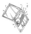
- FIG. 1is a perspective view of a portable computing device including a cooling system formed in accordance with the present invention
- FIG. 2is a perspective view of the portable computing device shown in FIG. 1, with the keypad and liquid crystal display removed for clarity of illustration;
- FIG. 3is a perspective view of a cooling system for a portable computing device formed in accordance with the present invention.
- FIG. 4is a broken-way, partially exploded perspective view, of the cooling system shown in FIG. 3;
- FIG. 5is a cross-sectional view of a second passive heat transfer device shown in FIG. 4, as taken along line 5 — 5 in FIG. 4;
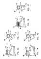
- FIGS. 6-11are elevational views of a display gudgeon formed in accordance with the present invention and having a variety of surface features formed on a pintle;
- FIGS. 12-17are elevational views of a base gudgeon formed in accordance with the present invention and showing a variety of surface features formed within the surface defining a journal in the gudgeon;
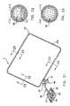
- FIG. 18is a perspective view of a cooling system formed in accordance with the present invention comprising a heat pipe;
- FIG. 19is a cross-sectional view of the heat pipe shown in FIGS. 18 and 31, as taken along line 19 — 19 in FIGS. 18 and 31;
- FIG. 20is a cross-sectional view of the heat pipe shown in FIGS. 18 and 31, as taken along line 20 — 20 in FIGS. 18 and 31;
- FIG. 21is a perspective view of an alternative cooling system formed in accordance with the present invention comprising a closed loop heat pipe;
- FIG. 22is a cross-sectional view of the heat pipe shown in FIG. 21, as taken along line 22 — 22 in FIG. 21;
- FIG. 23is a cross-sectional view of the heat pipe shown in FIG. 21, as taken along line 23 — 23 in FIG. 21;
- FIG. 24is a further alternative embodiment of cooling system formed in accordance with the present invention comprising a thermosiphon
- FIG. 25is a cross-sectional view of the thermosiphon as shown in FIG. 24, as taken along line 25 — 25 in FIG. 24;
- FIG. 26is a cross-sectional view of the thermosiphon as shown in FIG. 24, as taken along line 26 — 26 in FIG. 24;
- FIG. 27is yet a further alternative embodiment of a cooling system for a portable computing device formed in accordance with the present invention and comprising a loop thermosiphon;
- FIG. 28is a cross-sectional view of the loop thermosiphon shown in FIG. 27, as taken along line 28 — 28 in FIG. 27;
- FIG. 29is a cross-sectional view of the loop thermosiphon shown in FIG. 27, as taken along line 29 — 29 in FIG. 27;
- FIG. 30is a perspective view of the portable computing device shown in FIG. 1, with the keypad and liquid crystal display removed for clarity of illustration, and including a further alternative embodiment of a cooling system formed in accordance with the present invention
- FIG. 31is a perspective view of the cooling system shown in FIG. 30.
- FIG. 32is an exploded perspective view, of the cooling system shown in FIG. 31 .
- a cooling system 3 formed in accordance with the present inventionis sized and shaped so as to be mounted within a portion of a portable computing device, e.g., a personal digital assistant (PDA) or a notebook/laptop computer 5 .
- Portable computer 5includes a base 12 and a display housing 14 .
- Base 12has a generally rectangular shape with a bottom wall 16 , an annular peripheral wall 18 , and an open top side across which a keyboard structure 21 extends horizontally.
- a printed wiring boardis 22 mounted on bottom wall 16 , with a heat generating component, e.g., a processor chip 24 , being operatively mounted on a top side of printed wiring board 22 .
- a thermal block 27is positioned atop processor chip 24 to conductively receive operating heat during operation of portable computer 5 .
- a recessed slot 28is defined in the top surface of thermal block 27 so as to receive a portion of a heat transfer device, as will hereinafter be disclosed in further detail (FIG. 4 ).
- Display housing 14comprises a rectangular configuration generally complementary to base 12 , and includes a top wall 26 , an annular peripheral wall 29 , and an open bottom.
- a liquid crystal display screen 30extends across the open bottom, surrounded by annular peripheral wall 29 .
- a planar plate 34is often set within display housing 14 , along top wall 26 , i.e., behind liquid crystal display screen 30 .
- Planar plate 34is formed from a highly conductive material, e.g., copper, aluminum, or their alloys, and is arranged in thermal transfer engagement with portions of cooling system 3 .
- cooling system 3serves to (i) pivotally interconnect display housing 14 to a rear edge of base 12 so as to allow for pivotal movement between a generally upright, open operating orientation and a generally horizontal, closed position; and (ii) transfer a considerable amount of the operational heat from processor 24 to display housing 14 .
- cooling system 3comprises a display gudgeon 43 , a first passive heat transfer device 46 , a base gudgeon 49 , and a second passive heat transfer device 53 .
- display gudgeon 43includes a thermal block 57 , a support arm 60 , and a pintle 63 (FIGS. 6 - 11 ).
- Thermal block 57is formed from a highly thermally conductive material, e.g., copper, aluminum, or their alloys, and includes a recess or groove 66 defined in an outer surface.
- Support arm 60projects outwardly from an end of thermal block 57 .
- Pintle 63projects outwardly from a top end of support arm 60 so as to be positioned in substantially parallel relation to thermal block 57 , and often in parallel relation to recess or groove 66 .
- Pintle 63comprises a solid, generally cylindrical pin that includes texturing in its outer surfaces that helps to increase available surface area.
- a plurality of grooves 69may be defined in the outer surface of pintle 63 in parallel relation to one another (FIGS. 6 and 7 ), in a helical arrangement (FIGS. 8 and 9 ), or a knurled configuration (FIGS. 10 and 11) so as to enhance the thermal energy transfer between display gudgeon 43 and base gudgeon 49 .
- Base gudgeon 49includes a thermal block 67 , a support arm 70 , and a journal 73 (FIGS. 12 - 17 ).
- Thermal block 67is formed from a highly thermally conductive material, e.g., copper, aluminum, or their alloys, and includes a recess or groove 76 defined in an outer surface.
- Support arm 70projects outwardly from one end of thermal block 67 .
- Journal 73comprises a generally cylindrical blind hole, that extends inwardly from a top end of support arm 70 so as to be arranged in substantially parallel relation with thermal block 67 , and often in parallel relation to recess or groove 76 .
- a counter-sink 74is annularly defined around the entrance to journal 73 .
- Journal 73also includes texturing on the inner surface of support arm 70 , defining the blind hole, that is similar in pattern to the texturing formed on the outer surface of pintle 63 .
- a plurality of grooves 79may be defined in the inner surface of journal 73 in parallel relation to one another (FIGS. 12 and 13 ), in a helical arrangement (FIGS. 14 and 15 ), or a knurled configuration (FIGS. 16 and 17) so as to enhance the thermal energy transfer between display gudgeon 43 and base gudgeon 49 .
- first passive heat transfer device 46comprises a heat pipe formed as a vacuum tight tube 82 , a wick 85 , and a working fluid 87 .
- Tube 82is formed so as to comprise a straight, partially flattened evaporation end 89 and a condensation end 91 that is arranged at a substantially 90° angular relationship to evaporation end 89 .
- Tube 82is often a relatively long, somewhat flattened cylinder formed from a highly thermally conductive material, e.g., copper, aluminum, or their alloys, monel, or the like.
- a vapor space 93is defined by a central passageway extending along the longitudinal axis of vacuum tight tube 82 .
- Wick 85may comprise adjacent layers of screening or a sintered powder structure with interstices between the particles of powder.
- wick 85may comprise aluminum-silicon-carbide (AlSiC) or copper-silicon-carbide (CuSiC) having an average thickness of about 0.1 mm to 1.0 mm.
- Working fluid 87may comprise any of the well known two-phase vaporizable liquids, e.g., water alcohol, freon, etc.
- Heat pipe 46is formed according to the invention by drawing a partial vacuum within tube 82 , and then back-filling with a small quantity of working fluid 87 , e.g., just enough to saturate wick 85 just prior to final sealing of tube 82 by pinching and welding or otherwise hermetically sealing off both ends 89 and 91 .
- the atmosphere inside heat pipe 46is set by an equilibrium of liquid and vapor 92 .
- second passive heat transfer device 53is sized and shaped so as to be positioned within a portion of display housing 14 , in surrounding or substantially surrounding relation to planar plate 34 , so as to maximize heat transfer.
- second passive heat transfer device 53may comprise a heat pipe 100 , a thermosiphon 106 , or a loop thermosiphon 108 .
- heat pipe 100(FIGS. 18 and 21 - 23 ) is formed in accordance with the formation of heat pipe 46 , i.e., having vacuum tight tube 112 , a wick 115 , and a working fluid 117 .
- Heat pipe 100is often longer than heat pipe 46 , and may comprise a substantially rectilinear profile so as to match the shape of display housing 14 .
- heat pipe 100comprises a four mm tube that is flattened to three mm to increase surface overlap with planar plate 34 .
- Planar plate 34is often set within display housing 14 , along top wall 26 , and behind liquid crystal display screen 30 , and is connected in thermal transfer communication with condenser portions of heat pipe 100 , via conventional thermo-mechanical fasteners 107 (FIG. 2) or by soldering or brazing the edge portions of planar plate 34 to heat pipe 100 (shown in phantom in FIGS. 1 and 30 ).
- thermosiphon 106comprises a highly thermally conductive, closed tube 122 having an evaporator section 124 and a condenser section 126 . More particularly, evaporator section 124 of thermosiphon 106 is disposed along a bottom course of tube 122 , where the interior of tube 122 may be lined with a wick structure 127 to facilitate pooling of working fluid 117 in evaporator region 124 .
- Wick structure 127may comprise adjacent layers of screening or a sintered powder structure with interstices between the particles of powder, e.g., sintered powders of (AlSiC) or (CuSiC) having an average thickness of about 0.1 mm to 1.0 mm.
- Working fluid 117is disposed within tube 122 , and may comprise any of the well known two-phase vaporizable liquids, e.g., water alcohol, freon, etc.
- Condenser section 126normally does not contain a wick structure, and is connected in flow communication with evaporator section 124 , via the interior of tube 122 . Sealed ends 130 of condenser section 126 are often angled upwardly relative to evaporator section 124 so as to facilitate the return of working fluid 117 under the influence of gravity.
- loop thermosiphon 108comprises a highly thermally conductive, closed tube 132 having an evaporator section 134 , a condenser section 136 , a vapor conduit 138 , a condensate conduit 140 , and a wick structure 142 . More particularly, evaporator section 134 of loop thermosiphon 108 is disposed along a bottom course of tube 132 , where the interior of tube 132 is lined with wick structure 142 .
- Wick structure 142may comprise adjacent layers of screening or a sintered powder structure with interstices between the particles of powder, e.g., sintered powders of (AlSiC) or (CuSiC) having an average thickness of about 0.1 mm to 1.0 mm.
- Working fluid 117is disposed within tube 132 , and may comprise any of the well known two-phase vaporizable liquids, e.g., water alcohol, freon, etc.
- Condenser section 136is connected in flow communication with evaporator section 134 , via vapor conduit 138 and condensate conduit 140 , so as to form a closed loop.
- a mixture of liquid and vaporflows out of evaporator section 134 into vapor conduit 138 .
- the amount of liquid contained in this mixturemay vary from heavily saturated with liquid to pure vapor (no liquid); dependent upon the amount of heat that is absorbed by the liquid during the time it is resident within evaporator section 134 .
- the pressureincreases forcing the mixture of vapor and liquid to flow through vapor conduit 138 , toward condenser section 136 .
- the condensed working fluidflows back to evaporator section 134 through condensate conduit 140 .
- cooling system 3may comprise a third passive heat transfer device 143 that is sized and shaped so as to be positioned within a portion of base 12 , in surrounding or partially surrounding relation to the central processing unit, memory, hard drive, disk drives, and keyboard circuitry so as to further maximize heat transfer.
- Third passive heat transfer device 143may comprise a heat pipe 144 that is formed in accordance with the formation of heat pipes 46 and 100 , e.g., having vacuum tight tube 82 , a wick 85 , and a working fluid 87 (FIGS. 19 and 20 ).
- Heat pipe 144may have a similar contour to heat pipe 100 , and is often longer than heat pipe 46 .
- heat pipe 144comprises a substantially rectilinear profile so as to match the shape of base 12 .
- a thermal interface plate 145is positioned within base 12 in intimate thermal communication with evaporator end 89 of heat pipe 46 .
- a portion of heat pipe 144is mounted within a slot in thermal interface plate 145 and fastened in place by soldering or brazing.
- cooling system 3is assembled to PDA or laptop computer 5 in the following manner.
- Thermal block 27is assembled to processor 24 and arranged in intimate thermal communication by the use of thermal epoxy, thermal grease, or the like.
- slot 28is exposed on the top of thermal block 27 .
- evaporator end 89 of first passive heat transfer device 46is positioned within slot 28 so as to create a thermal communication link between thermal block 27 and evaporator end 89 .
- Base gudgeon 49is assembled to condenser end 91 of first passive heat transfer device 46 by arranging recess groove 76 in confronting parallel relation to condenser end 91 . Once in this position, base gudgeon 49 is moved toward first passive heat transfer device 46 such that condenser end 91 is received within recessed groove 76 . Condenser end 91 is arranged so as to be thermally engaged with base gudgeon 49 by the use of thermal epoxy, thermal grease, or a braze, solder or weld between that portion of tube 82 that defines condensation end 91 and the surface of base gudgeon 49 that the defines recess groove 76 .
- Display gudgeon 43is assembled to second passive heat transfer device 53 by arranging recess groove 66 in confronting parallel relation with the evaporator section of second passive heat transfer device 53 . Once in this position, display gudgeon 43 is moved toward second passive heat transfer device 53 such that a portion of the evaporator section is received within recessed groove 66 . A thermal communication bond is formed between display gudgeon 43 and second passive heat transfer device 53 by the use of thermal epoxy, thermal grease, soldering, brazing, or welding.
- journal 73is first filled with an appropriate thermal grease to facilitate a low thermal resistance at the interface between display gudgeon 43 and base gudgeon 49 .
- Pintle 63is then moved into coaxially aligned confronting relation with journal 73 .
- a sealing grommet 150may be positioned in counter-sink 74 of base gudgeon 49 prior to assembly so as to prevent the thermal grease from being displaced from journal 73 during insertion and operation of pintle 63 .
- Sealing grommet 150also acts to prevent the thermal grease disposed between pintle 63 and the surface of journal 73 from drying up during the operating life of portable computing device 5 .
- Display gudgeon 43is then moved toward base gudgeon 49 so that pintle 63 enters journal 73 .
- a hinged thermal interconnectionis formed between first passive heat transfer device 46 and second passive heat transfer device 53 .
- thermal block 27During operation of portable computer 5 , operating heat from processor 24 is conducted to evaporation end 89 of heat pipe 46 through thermal block 27 . Operating heat received by evaporation end 89 is transferred along the length of heat pipe 46 to its condensing/hinge member end 91 where the thermal energy is conductively transferred through thermal block 57 of base gudgeon 49 to pintle 63 . The thermal energy is then conductively transferred across the thermal boundary between journal 73 and pintle 63 by means of a high performance thermal grease, e.g., a thermal grease, such as a silver filled grease or the like. The thickness of the thermal grease will vary depending upon the performance requirements of portable computer 5 .
- a high performance thermal greasee.g., a thermal grease, such as a silver filled grease or the like. The thickness of the thermal grease will vary depending upon the performance requirements of portable computer 5 .
- thermal energyis transferred to display gudgeon 43 , it is conducted through support arm 70 and thermal block 67 to second passive heat transfer device 53 and dissipated to the ambient environment, via plate 34 in top wall 26 of display housing 14 . It will be understood that in the embodiment shown in FIGS. 30-32, operating heat is also transferred to the portion of heat pipe 144 positioned within thermal interface 145 so that it can be distributed within base 12 to further enhance heat transfer away from processor 24 .
Landscapes
- Engineering & Computer Science (AREA)
- Theoretical Computer Science (AREA)
- Computer Hardware Design (AREA)
- Human Computer Interaction (AREA)
- Physics & Mathematics (AREA)
- General Engineering & Computer Science (AREA)
- General Physics & Mathematics (AREA)
- Cooling Or The Like Of Electrical Apparatus (AREA)
Abstract
Description
Claims (21)
Priority Applications (1)
| Application Number | Priority Date | Filing Date | Title |
|---|---|---|---|
| US10/280,726US6771498B2 (en) | 2002-10-25 | 2002-10-25 | Cooling system for hinged portable computing device |
Applications Claiming Priority (1)
| Application Number | Priority Date | Filing Date | Title |
|---|---|---|---|
| US10/280,726US6771498B2 (en) | 2002-10-25 | 2002-10-25 | Cooling system for hinged portable computing device |
Publications (2)
| Publication Number | Publication Date |
|---|---|
| US20040080908A1 US20040080908A1 (en) | 2004-04-29 |
| US6771498B2true US6771498B2 (en) | 2004-08-03 |
Family
ID=32107008
Family Applications (1)
| Application Number | Title | Priority Date | Filing Date |
|---|---|---|---|
| US10/280,726Expired - LifetimeUS6771498B2 (en) | 2002-10-25 | 2002-10-25 | Cooling system for hinged portable computing device |
Country Status (1)
| Country | Link |
|---|---|
| US (1) | US6771498B2 (en) |
Cited By (32)
| Publication number | Priority date | Publication date | Assignee | Title |
|---|---|---|---|---|
| US20040070940A1 (en)* | 2002-10-15 | 2004-04-15 | Kabushiki Kaisha Toshiba | Electronic apparatus having a circulation path of liquid coolant to cool a heat-generating component |
| US20050160752A1 (en)* | 2004-01-23 | 2005-07-28 | Nanocoolers, Inc. | Apparatus and methodology for cooling of high power density devices by electrically conducting fluids |
| US20060267522A1 (en)* | 2005-05-13 | 2006-11-30 | Benq Corporation | Electronic device |
| US20070070599A1 (en)* | 2005-09-23 | 2007-03-29 | Hon Hai Precision Industry Co., Ltd. | Portable computer |
| US20070171608A1 (en)* | 2006-01-24 | 2007-07-26 | Ama Precision Inc. | Heat exchange module |
| US20070195500A1 (en)* | 2006-02-22 | 2007-08-23 | Foxconn Technology Co., Ltd. | Heat dissipation apparatus |
| US20080130221A1 (en)* | 2006-12-02 | 2008-06-05 | Krishnakumar Varadarajan | Thermal hinge for lid cooling |
| US20090021908A1 (en)* | 2007-07-18 | 2009-01-22 | Chandrakant Patel | System and method for cooling an electronic device |
| US20090279262A1 (en)* | 2008-05-12 | 2009-11-12 | Meng-Cheng Huang | Heat dissipating structure |
| US20090279258A1 (en)* | 2008-05-12 | 2009-11-12 | Moore David A | Hinge connector with liquid coolant path |
| US20090310307A1 (en)* | 2008-06-16 | 2009-12-17 | Kuo-Len Lin | Integrated heat-dissipating device for portable electronic product |
| US20100091450A1 (en)* | 2008-10-14 | 2010-04-15 | Foxconn Technology Co., Ltd. | Heat dissipating hinge for portable electronic device |
| US20110059346A1 (en)* | 2009-09-07 | 2011-03-10 | Samsung Electronics Co., Ltd. | Cooling system and battery cooling system |
| US8373980B2 (en) | 2010-10-22 | 2013-02-12 | Explore Technologies Corp. | System for mounting a display to a computer |
| US20140009888A1 (en)* | 2011-12-28 | 2014-01-09 | Mark MacDonald | Electronic device having a passive heat exchange device |
| US8893513B2 (en) | 2012-05-07 | 2014-11-25 | Phononic Device, Inc. | Thermoelectric heat exchanger component including protective heat spreading lid and optimal thermal interface resistance |
| US8991194B2 (en) | 2012-05-07 | 2015-03-31 | Phononic Devices, Inc. | Parallel thermoelectric heat exchange systems |
| US9007760B2 (en) | 2010-04-05 | 2015-04-14 | Apple Inc. | Computer hinge having a hollow clutch |
| US9134757B2 (en) | 2012-09-28 | 2015-09-15 | Intel Corporation | Electronic device having passive cooling |
| US9593871B2 (en) | 2014-07-21 | 2017-03-14 | Phononic Devices, Inc. | Systems and methods for operating a thermoelectric module to increase efficiency |
| US20180329464A1 (en)* | 2017-05-15 | 2018-11-15 | Quanta Computer Inc. | Electronic device with heat-dissipation structure |
| US20190129480A1 (en)* | 2018-12-19 | 2019-05-02 | Intel Corporation | Laptop computer with integral cooling |
| US20190226768A1 (en)* | 2018-01-19 | 2019-07-25 | Asia Vital Components Co., Ltd. | Two-phase fluid heat transfer structure |
| US10458683B2 (en) | 2014-07-21 | 2019-10-29 | Phononic, Inc. | Systems and methods for mitigating heat rejection limitations of a thermoelectric module |
| US20200008321A1 (en)* | 2018-06-29 | 2020-01-02 | Juniper Networks, Inc. | Thermal management with variable conductance heat pipe |
| US10775842B1 (en)* | 2019-05-29 | 2020-09-15 | Inventec (Pudong) Technology Corporation | Portable electronic device |
| US10802555B2 (en)* | 2018-04-13 | 2020-10-13 | Dell Products L.P. | Information handling system thermally conductive hinge |
| US10936031B2 (en) | 2018-04-13 | 2021-03-02 | Dell Products L.P. | Information handling system dynamic thermal transfer control |
| US10969841B2 (en) | 2018-04-13 | 2021-04-06 | Dell Products L.P. | Information handling system housing integrated vapor chamber |
| US20210109575A1 (en)* | 2018-10-26 | 2021-04-15 | Huawei Technologies Co., Ltd. | Folding Device and Heat Dissipation Apparatus |
| US20220061194A1 (en)* | 2020-08-19 | 2022-02-24 | Beijing Xiaomi Mobile Software Co., Ltd. | Support assembly and display device |
| US11829214B2 (en) | 2022-04-06 | 2023-11-28 | Microsoft Technology Licensing, Llc | Device cooling |
Families Citing this family (18)
| Publication number | Priority date | Publication date | Assignee | Title |
|---|---|---|---|---|
| EP1422594A3 (en)* | 2002-11-22 | 2005-08-17 | Contec Steuerungstechnik & Automation Gesellschaft m.b.H. | A method and an apparatus for cooling a portable computer |
| TWI348885B (en)* | 2007-11-30 | 2011-09-11 | Ama Precision Inc | Heat dissipation module |
| CN101369173B (en)* | 2008-06-18 | 2015-08-12 | 秦彪 | portable computer |
| US20090323276A1 (en)* | 2008-06-25 | 2009-12-31 | Mongia Rajiv K | High performance spreader for lid cooling applications |
| US7746631B2 (en)* | 2008-08-29 | 2010-06-29 | Apple Inc. | Methods and apparatus for cooling electronic devices using thermally conductive hinge assemblies |
| TWI488574B (en)* | 2011-07-18 | 2015-06-11 | Au Optronics Corp | Heat-dissipation structure and portable folding electronic apparatus therewith |
| US9182794B2 (en)* | 2011-11-30 | 2015-11-10 | Google Inc. | Notebook metal hinge as heat sink element |
| US9148979B2 (en)* | 2012-10-08 | 2015-09-29 | Qualcomm Incorporated | Heat dissipating apparatus for folding electronic devices |
| JP2014232385A (en)* | 2013-05-28 | 2014-12-11 | ソニー株式会社 | Electronic device |
| US9965003B2 (en)* | 2015-07-09 | 2018-05-08 | Htc Corporation | Electronic assembly and electronic device |
| US9848515B1 (en)* | 2016-05-27 | 2017-12-19 | Advanced Micro Devices, Inc. | Multi-compartment computing device with shared cooling device |
| JP6469183B2 (en)* | 2017-07-25 | 2019-02-13 | レノボ・シンガポール・プライベート・リミテッド | Electronics |
| WO2020000077A1 (en)* | 2018-06-27 | 2020-01-02 | Huawei Technologies Co., Ltd. | Thermally conducting hinge arrangement for a foldable electronic device |
| US11153990B2 (en)* | 2018-12-21 | 2021-10-19 | Intel Corporation | Movable heat-transfer system |
| US10932393B2 (en)* | 2019-03-30 | 2021-02-23 | Intel Corporation | Torsional heat pipe |
| JP6828085B2 (en)* | 2019-05-09 | 2021-02-10 | レノボ・シンガポール・プライベート・リミテッド | Heat transport equipment and electronics |
| US10721842B1 (en)* | 2019-07-29 | 2020-07-21 | Hewlett Packard Enterprise Development Lp | Flexible thermal cooling assembly |
| US20220007541A1 (en)* | 2020-07-06 | 2022-01-06 | Crystal Group, Inc. | Dual inline memory module heat sink for conduction cooled environments |
Citations (29)
| Publication number | Priority date | Publication date | Assignee | Title |
|---|---|---|---|---|
| US3831664A (en) | 1973-11-07 | 1974-08-27 | Boeing Co | Heat pipe interfaces |
| US4345642A (en) | 1980-12-24 | 1982-08-24 | Thermacore, Inc. | Articulated heat pipes |
| US5117901A (en) | 1991-02-01 | 1992-06-02 | Cullimore Brent A | Heat transfer system having a flexible deployable condenser tube |
| US5383340A (en) | 1994-03-24 | 1995-01-24 | Aavid Laboratories, Inc. | Two-phase cooling system for laptop computers |
| US5588483A (en)* | 1995-01-27 | 1996-12-31 | Diamond Electric Mfg. Co., Ltd. | Heat radiating apparatus |
| US5621613A (en)* | 1995-05-16 | 1997-04-15 | Intel Corporation | Apparatus for dissipating heat in a hinged computing device |
| US5646822A (en)* | 1995-08-30 | 1997-07-08 | Intel Corporation | Heat pipe exchanger system for cooling a hinged computing device |
| US5757615A (en)* | 1996-07-01 | 1998-05-26 | Compaq Computer Corporation | Liquid cooled computer apparatus and associated methods |
| US5781409A (en)* | 1996-12-19 | 1998-07-14 | Compaq Computer Corporation | Heat dissipating lid hinge structure with laterally offset heat pipe end portions |
| US5796581A (en)* | 1997-07-30 | 1998-08-18 | International Business Machines Corporation | Rotational joint for hinged heat pipe cooling of a computer |
| US5822187A (en)* | 1996-10-25 | 1998-10-13 | Thermal Corp. | Heat pipes inserted into first and second parallel holes in a block for transferring heat between hinged devices |
| US5832987A (en)* | 1997-03-21 | 1998-11-10 | Lowry; David A. | Rotatable heat transfer coupling |
| US5847925A (en)* | 1997-08-12 | 1998-12-08 | Compaq Computer Corporation | System and method for transferring heat between movable portions of a computer |
| US5880929A (en)* | 1997-12-01 | 1999-03-09 | Intel Corporation | Heat exchanger system for cooling a hinged computing device |
| US6031716A (en)* | 1998-09-08 | 2000-02-29 | International Business Machines Corporation | Computer incorporating heat dissipator with hinged heat pipe arrangement for enhanced cooling capacity |
| US6097596A (en)* | 1998-02-12 | 2000-08-01 | International Business Machines Corporation | Portable computer rotational heat pipe heat transfer |
| US6097597A (en)* | 1998-06-30 | 2000-08-01 | Mitsubishi Denki Kabushiki Kaisha | Thermo-siphon and manufacturing method of thermo-siphon and information processing apparatus |
| US6122166A (en) | 1994-09-16 | 2000-09-19 | Fujikura Ltd. | Personal computer cooling device having hinged heat pipe |
| US6134106A (en)* | 1999-12-08 | 2000-10-17 | Loyalty Founder Enterprise Co., Ltd. | Winding chain dissipating unit suitable for electronic device |
| US6175493B1 (en)* | 1998-10-16 | 2001-01-16 | Dell Usa, Lp | Heat transfer from base to display portion of a portable computer |
| US6185102B1 (en)* | 1999-09-07 | 2001-02-06 | Foxconn Precision Components, Co., Ltd. | Heat transfer device |
| JP2001134345A (en)* | 1999-11-09 | 2001-05-18 | Matsushita Electric Ind Co Ltd | Hinge and electronic device using the same |
| US6288896B1 (en)* | 1998-07-02 | 2001-09-11 | Acer Incorporated | Heat dissipation system for a laptop computer using a heat pipe |
| US6341062B1 (en)* | 2000-03-06 | 2002-01-22 | International Business Machines Corp. | Thermal transfer hinge for hinged mobile computing device and method of heat transfer |
| US6377452B1 (en)* | 1998-12-18 | 2002-04-23 | Furukawa Electric Co., Ltd. | Heat pipe hinge structure for electronic device |
| US6507488B1 (en)* | 1999-04-30 | 2003-01-14 | International Business Machines Corporation | Formed hinges with heat pipes |
| US6556439B2 (en)* | 2000-06-29 | 2003-04-29 | Kabushiki Kaisha Toshiba | Cooling unit for cooling heat generating component and electronic apparatus equipped with the cooling unit |
| US6587336B2 (en)* | 2001-06-27 | 2003-07-01 | International Business Machines Corporation | Cooling system for portable electronic and computer devices |
| US6611425B2 (en)* | 2001-02-06 | 2003-08-26 | Hitachi, Ltd. | Electronic apparatus |
- 2002
- 2002-10-25USUS10/280,726patent/US6771498B2/ennot_activeExpired - Lifetime
Patent Citations (29)
| Publication number | Priority date | Publication date | Assignee | Title |
|---|---|---|---|---|
| US3831664A (en) | 1973-11-07 | 1974-08-27 | Boeing Co | Heat pipe interfaces |
| US4345642A (en) | 1980-12-24 | 1982-08-24 | Thermacore, Inc. | Articulated heat pipes |
| US5117901A (en) | 1991-02-01 | 1992-06-02 | Cullimore Brent A | Heat transfer system having a flexible deployable condenser tube |
| US5383340A (en) | 1994-03-24 | 1995-01-24 | Aavid Laboratories, Inc. | Two-phase cooling system for laptop computers |
| US6122166A (en) | 1994-09-16 | 2000-09-19 | Fujikura Ltd. | Personal computer cooling device having hinged heat pipe |
| US5588483A (en)* | 1995-01-27 | 1996-12-31 | Diamond Electric Mfg. Co., Ltd. | Heat radiating apparatus |
| US5621613A (en)* | 1995-05-16 | 1997-04-15 | Intel Corporation | Apparatus for dissipating heat in a hinged computing device |
| US5646822A (en)* | 1995-08-30 | 1997-07-08 | Intel Corporation | Heat pipe exchanger system for cooling a hinged computing device |
| US5757615A (en)* | 1996-07-01 | 1998-05-26 | Compaq Computer Corporation | Liquid cooled computer apparatus and associated methods |
| US5822187A (en)* | 1996-10-25 | 1998-10-13 | Thermal Corp. | Heat pipes inserted into first and second parallel holes in a block for transferring heat between hinged devices |
| US5781409A (en)* | 1996-12-19 | 1998-07-14 | Compaq Computer Corporation | Heat dissipating lid hinge structure with laterally offset heat pipe end portions |
| US5832987A (en)* | 1997-03-21 | 1998-11-10 | Lowry; David A. | Rotatable heat transfer coupling |
| US5796581A (en)* | 1997-07-30 | 1998-08-18 | International Business Machines Corporation | Rotational joint for hinged heat pipe cooling of a computer |
| US5847925A (en)* | 1997-08-12 | 1998-12-08 | Compaq Computer Corporation | System and method for transferring heat between movable portions of a computer |
| US5880929A (en)* | 1997-12-01 | 1999-03-09 | Intel Corporation | Heat exchanger system for cooling a hinged computing device |
| US6097596A (en)* | 1998-02-12 | 2000-08-01 | International Business Machines Corporation | Portable computer rotational heat pipe heat transfer |
| US6097597A (en)* | 1998-06-30 | 2000-08-01 | Mitsubishi Denki Kabushiki Kaisha | Thermo-siphon and manufacturing method of thermo-siphon and information processing apparatus |
| US6288896B1 (en)* | 1998-07-02 | 2001-09-11 | Acer Incorporated | Heat dissipation system for a laptop computer using a heat pipe |
| US6031716A (en)* | 1998-09-08 | 2000-02-29 | International Business Machines Corporation | Computer incorporating heat dissipator with hinged heat pipe arrangement for enhanced cooling capacity |
| US6175493B1 (en)* | 1998-10-16 | 2001-01-16 | Dell Usa, Lp | Heat transfer from base to display portion of a portable computer |
| US6377452B1 (en)* | 1998-12-18 | 2002-04-23 | Furukawa Electric Co., Ltd. | Heat pipe hinge structure for electronic device |
| US6507488B1 (en)* | 1999-04-30 | 2003-01-14 | International Business Machines Corporation | Formed hinges with heat pipes |
| US6185102B1 (en)* | 1999-09-07 | 2001-02-06 | Foxconn Precision Components, Co., Ltd. | Heat transfer device |
| JP2001134345A (en)* | 1999-11-09 | 2001-05-18 | Matsushita Electric Ind Co Ltd | Hinge and electronic device using the same |
| US6134106A (en)* | 1999-12-08 | 2000-10-17 | Loyalty Founder Enterprise Co., Ltd. | Winding chain dissipating unit suitable for electronic device |
| US6341062B1 (en)* | 2000-03-06 | 2002-01-22 | International Business Machines Corp. | Thermal transfer hinge for hinged mobile computing device and method of heat transfer |
| US6556439B2 (en)* | 2000-06-29 | 2003-04-29 | Kabushiki Kaisha Toshiba | Cooling unit for cooling heat generating component and electronic apparatus equipped with the cooling unit |
| US6611425B2 (en)* | 2001-02-06 | 2003-08-26 | Hitachi, Ltd. | Electronic apparatus |
| US6587336B2 (en)* | 2001-06-27 | 2003-07-01 | International Business Machines Corporation | Cooling system for portable electronic and computer devices |
Cited By (57)
| Publication number | Priority date | Publication date | Assignee | Title |
|---|---|---|---|---|
| US6845011B2 (en)* | 2002-10-15 | 2005-01-18 | Kabushiki Kaisha Toshiba | Electronic apparatus having a circulation path of liquid coolant to cool a heat-generating component |
| US20040070940A1 (en)* | 2002-10-15 | 2004-04-15 | Kabushiki Kaisha Toshiba | Electronic apparatus having a circulation path of liquid coolant to cool a heat-generating component |
| US20080239672A1 (en)* | 2004-01-23 | 2008-10-02 | Nanocoolers, Inc. | Cooling of High Power Density Devices Using Electrically Conducting Fluids |
| US20050160752A1 (en)* | 2004-01-23 | 2005-07-28 | Nanocoolers, Inc. | Apparatus and methodology for cooling of high power density devices by electrically conducting fluids |
| US20060267522A1 (en)* | 2005-05-13 | 2006-11-30 | Benq Corporation | Electronic device |
| US20070070599A1 (en)* | 2005-09-23 | 2007-03-29 | Hon Hai Precision Industry Co., Ltd. | Portable computer |
| US20070171608A1 (en)* | 2006-01-24 | 2007-07-26 | Ama Precision Inc. | Heat exchange module |
| US20070195500A1 (en)* | 2006-02-22 | 2007-08-23 | Foxconn Technology Co., Ltd. | Heat dissipation apparatus |
| US20080130221A1 (en)* | 2006-12-02 | 2008-06-05 | Krishnakumar Varadarajan | Thermal hinge for lid cooling |
| US20090021908A1 (en)* | 2007-07-18 | 2009-01-22 | Chandrakant Patel | System and method for cooling an electronic device |
| US8392035B2 (en) | 2007-07-18 | 2013-03-05 | Hewlett-Packard Development Company, L. P. | System and method for cooling an electronic device |
| US7903409B2 (en) | 2007-07-18 | 2011-03-08 | Hewlett-Packard Development Company, L.P. | System and method for cooling an electronic device |
| US20090279262A1 (en)* | 2008-05-12 | 2009-11-12 | Meng-Cheng Huang | Heat dissipating structure |
| US20090279258A1 (en)* | 2008-05-12 | 2009-11-12 | Moore David A | Hinge connector with liquid coolant path |
| US7791876B2 (en) | 2008-05-12 | 2010-09-07 | Hewlett-Packard Development Company, L.P. | Hinge connector with liquid coolant path |
| US20090310307A1 (en)* | 2008-06-16 | 2009-12-17 | Kuo-Len Lin | Integrated heat-dissipating device for portable electronic product |
| US7656665B2 (en)* | 2008-06-16 | 2010-02-02 | Golden Sun News Techniques Co., Ltd. | Integrated heat-dissipating device for portable electronic product |
| US20100091450A1 (en)* | 2008-10-14 | 2010-04-15 | Foxconn Technology Co., Ltd. | Heat dissipating hinge for portable electronic device |
| US7907397B2 (en)* | 2008-10-14 | 2011-03-15 | Foxconn Technology Co., Ltd. | Heat dissipating hinge for portable electronic device |
| US20110059346A1 (en)* | 2009-09-07 | 2011-03-10 | Samsung Electronics Co., Ltd. | Cooling system and battery cooling system |
| US9007760B2 (en) | 2010-04-05 | 2015-04-14 | Apple Inc. | Computer hinge having a hollow clutch |
| US8373980B2 (en) | 2010-10-22 | 2013-02-12 | Explore Technologies Corp. | System for mounting a display to a computer |
| US8699220B2 (en) | 2010-10-22 | 2014-04-15 | Xplore Technologies Corp. | Computer with removable cartridge |
| US8699216B2 (en) | 2010-10-22 | 2014-04-15 | Xplore Technologies Corp. | Computer with door-mounted electronics |
| US9383788B2 (en) | 2010-10-22 | 2016-07-05 | Xplore Technologies Corp. | Computer with high intensity screen |
| US8941981B2 (en) | 2010-10-22 | 2015-01-27 | Xplore Technologies Corp. | Computer with high intensity screen |
| US20140009888A1 (en)* | 2011-12-28 | 2014-01-09 | Mark MacDonald | Electronic device having a passive heat exchange device |
| US9268377B2 (en)* | 2011-12-28 | 2016-02-23 | Intel Corporation | Electronic device having a passive heat exchange device |
| US9103572B2 (en) | 2012-05-07 | 2015-08-11 | Phononic Devices, Inc. | Physically separated hot side and cold side heat sinks in a thermoelectric refrigeration system |
| US9234682B2 (en) | 2012-05-07 | 2016-01-12 | Phononic Devices, Inc. | Two-phase heat exchanger mounting |
| US8991194B2 (en) | 2012-05-07 | 2015-03-31 | Phononic Devices, Inc. | Parallel thermoelectric heat exchange systems |
| US9310111B2 (en) | 2012-05-07 | 2016-04-12 | Phononic Devices, Inc. | Systems and methods to mitigate heat leak back in a thermoelectric refrigeration system |
| US9341394B2 (en) | 2012-05-07 | 2016-05-17 | Phononic Devices, Inc. | Thermoelectric heat exchange system comprising cascaded cold side heat sinks |
| US8893513B2 (en) | 2012-05-07 | 2014-11-25 | Phononic Device, Inc. | Thermoelectric heat exchanger component including protective heat spreading lid and optimal thermal interface resistance |
| US10012417B2 (en) | 2012-05-07 | 2018-07-03 | Phononic, Inc. | Thermoelectric refrigeration system control scheme for high efficiency performance |
| US9134757B2 (en) | 2012-09-28 | 2015-09-15 | Intel Corporation | Electronic device having passive cooling |
| US10458683B2 (en) | 2014-07-21 | 2019-10-29 | Phononic, Inc. | Systems and methods for mitigating heat rejection limitations of a thermoelectric module |
| US9593871B2 (en) | 2014-07-21 | 2017-03-14 | Phononic Devices, Inc. | Systems and methods for operating a thermoelectric module to increase efficiency |
| US20180329464A1 (en)* | 2017-05-15 | 2018-11-15 | Quanta Computer Inc. | Electronic device with heat-dissipation structure |
| US10209748B2 (en)* | 2017-05-15 | 2019-02-19 | Quanta Computer Inc. | Electronic device with heat-dissipation structure |
| US10578368B2 (en)* | 2018-01-19 | 2020-03-03 | Asia Vital Components Co., Ltd. | Two-phase fluid heat transfer structure |
| US20190226768A1 (en)* | 2018-01-19 | 2019-07-25 | Asia Vital Components Co., Ltd. | Two-phase fluid heat transfer structure |
| US10802555B2 (en)* | 2018-04-13 | 2020-10-13 | Dell Products L.P. | Information handling system thermally conductive hinge |
| US10936031B2 (en) | 2018-04-13 | 2021-03-02 | Dell Products L.P. | Information handling system dynamic thermal transfer control |
| US10969841B2 (en) | 2018-04-13 | 2021-04-06 | Dell Products L.P. | Information handling system housing integrated vapor chamber |
| US11653477B2 (en)* | 2018-06-29 | 2023-05-16 | Juniper Networks, Inc. | Thermal management with variable conductance heat pipe |
| US20200008321A1 (en)* | 2018-06-29 | 2020-01-02 | Juniper Networks, Inc. | Thermal management with variable conductance heat pipe |
| US11051431B2 (en)* | 2018-06-29 | 2021-06-29 | Juniper Networks, Inc. | Thermal management with variable conductance heat pipe |
| US20210227723A1 (en)* | 2018-06-29 | 2021-07-22 | Juniper Networks, Inc. | Thermal management with variable conductance heat pipe |
| US20210109575A1 (en)* | 2018-10-26 | 2021-04-15 | Huawei Technologies Co., Ltd. | Folding Device and Heat Dissipation Apparatus |
| US11847003B2 (en)* | 2018-10-26 | 2023-12-19 | Huawei Technologies Co., Ltd. | Folding device and heat dissipation apparatus |
| US20190129480A1 (en)* | 2018-12-19 | 2019-05-02 | Intel Corporation | Laptop computer with integral cooling |
| US10747277B2 (en)* | 2018-12-19 | 2020-08-18 | Intel Corporation | Laptop computer with integral cooling |
| US10775842B1 (en)* | 2019-05-29 | 2020-09-15 | Inventec (Pudong) Technology Corporation | Portable electronic device |
| US11564338B2 (en)* | 2020-08-19 | 2023-01-24 | Beijing Xiaomi Mobile Software Co., Ltd. | Support assembly and display device |
| US20220061194A1 (en)* | 2020-08-19 | 2022-02-24 | Beijing Xiaomi Mobile Software Co., Ltd. | Support assembly and display device |
| US11829214B2 (en) | 2022-04-06 | 2023-11-28 | Microsoft Technology Licensing, Llc | Device cooling |
Also Published As
| Publication number | Publication date |
|---|---|
| US20040080908A1 (en) | 2004-04-29 |
Similar Documents
| Publication | Publication Date | Title |
|---|---|---|
| US6771498B2 (en) | Cooling system for hinged portable computing device | |
| JP3017837B2 (en) | Electronic equipment | |
| US6507488B1 (en) | Formed hinges with heat pipes | |
| US6341062B1 (en) | Thermal transfer hinge for hinged mobile computing device and method of heat transfer | |
| US5781409A (en) | Heat dissipating lid hinge structure with laterally offset heat pipe end portions | |
| US6966361B2 (en) | Bi-level heat sink | |
| US6125035A (en) | Heat sink assembly with rotating heat pipe | |
| US5458189A (en) | Two-phase component cooler | |
| US5796581A (en) | Rotational joint for hinged heat pipe cooling of a computer | |
| US6175493B1 (en) | Heat transfer from base to display portion of a portable computer | |
| US5933323A (en) | Electronic component lid that provides improved thermal dissipation | |
| US5557500A (en) | Heat dissipating arrangement in a portable computer | |
| US8039952B2 (en) | System and method for dissipating heat from a semiconductor module | |
| Xie et al. | The use of heat pipes in personal computers | |
| US20040190255A1 (en) | Soft cooling jacket for electronic device | |
| KR20040039345A (en) | Cooling unit for cooling heat generating component | |
| US20050122678A1 (en) | Docking station cooling system including liquid-filled hollow structure | |
| US7403393B2 (en) | Apparatus and system for cooling heat producing components | |
| WO2003087695A1 (en) | Self-excited vibration heat pipe and computer with the heat pipe | |
| US20050045310A1 (en) | Heat pipe, cooling unit having the heat pipe, and electronic apparatus having the cooling unit | |
| US7262966B2 (en) | Heat sink modules for light and thin electronic equipment | |
| US8743547B2 (en) | Electronic device having cooling structure | |
| Xie et al. | The use of heat pipes in the cooling of portables with high power packages-A case study with the Pentium processor-based notebooks and sub-notebooks | |
| JP2000002493A (en) | Cooling unit and cooling structure using it | |
| JP2014085055A (en) | Cooling device |
Legal Events
| Date | Code | Title | Description |
|---|---|---|---|
| AS | Assignment | Owner name:THERMAL CORP, DELAWARE Free format text:ASSIGNMENT OF ASSIGNORS INTEREST;ASSIGNORS:WANG, HWAI-MING;CHIANG, WEI-CHIEH;LIU, HSIEN-TSANG;REEL/FRAME:013435/0308 Effective date:20021022 | |
| STCF | Information on status: patent grant | Free format text:PATENTED CASE | |
| FEPP | Fee payment procedure | Free format text:PAYER NUMBER DE-ASSIGNED (ORIGINAL EVENT CODE: RMPN); ENTITY STATUS OF PATENT OWNER: SMALL ENTITY Free format text:PAYOR NUMBER ASSIGNED (ORIGINAL EVENT CODE: ASPN); ENTITY STATUS OF PATENT OWNER: SMALL ENTITY | |
| FPAY | Fee payment | Year of fee payment:4 | |
| REMI | Maintenance fee reminder mailed | ||
| AS | Assignment | Owner name:NATIONAL PENN BANK, PENNSYLVANIA Free format text:SECURITY AGREEMENT;ASSIGNORS:THERMAL CORP.;FSBO VENTURE ACQUISITIONS, INC.;REEL/FRAME:021398/0300 Effective date:20080430 Owner name:NATIONAL PENN BANK,PENNSYLVANIA Free format text:SECURITY AGREEMENT;ASSIGNORS:THERMAL CORP.;FSBO VENTURE ACQUISITIONS, INC.;REEL/FRAME:021398/0300 Effective date:20080430 | |
| FEPP | Fee payment procedure | Free format text:PAT HOLDER CLAIMS SMALL ENTITY STATUS, ENTITY STATUS SET TO SMALL (ORIGINAL EVENT CODE: LTOS); ENTITY STATUS OF PATENT OWNER: SMALL ENTITY | |
| AS | Assignment | Owner name:SOVEREIGN BANK, PENNSYLVANIA Free format text:SECURITY AGREEMENT;ASSIGNORS:THERMACORE, INC.;THERMAL CORP.;REEL/FRAME:026039/0865 Effective date:20101230 | |
| FPAY | Fee payment | Year of fee payment:8 | |
| AS | Assignment | Owner name:PINE STREET CAPITAL PARTNERS II, L.P., NEW YORK Free format text:SECURITY INTEREST;ASSIGNOR:THERMAL CORP.;REEL/FRAME:035134/0363 Effective date:20141113 | |
| FPAY | Fee payment | Year of fee payment:12 | |
| AS | Assignment | Owner name:ANTARES CAPITAL LP, AS AGENT, ILLINOIS Free format text:SECURITY INTEREST;ASSIGNOR:THERMAL CORP.;REEL/FRAME:040355/0672 Effective date:20161013 | |
| AS | Assignment | Owner name:THERMAL CORP., NEW HAMPSHIRE Free format text:RELEASE OF SECURITY INTEREST RECORDED AT REEL/FRAME 035134/0363;ASSIGNOR:PINE STREET CAPITAL PARTNERS II, L.P.;REEL/FRAME:040425/0584 Effective date:20161013 | |
| AS | Assignment | Owner name:THERMAL CORP., NEW HAMPSHIRE Free format text:RELEASE OF SECURITY INTEREST RECORDED AT REEL/FRAME 026039/0865;ASSIGNOR:SANTANDER BANK, N.A. F/K/A SOVEREIGN BANK;REEL/FRAME:040508/0649 Effective date:20161013 Owner name:THERMAL CORP., NEW HAMPSHIRE Free format text:RELEASE OF SECURITY INTEREST RECORDED AT REEL/FRAME 021398/0300;ASSIGNOR:NATIONAL PENN BANK;REEL/FRAME:040508/0620 Effective date:20101230 Owner name:THERMACORE, INC. F/K/A FSBO VENTURE ACQUISITIONS, Free format text:RELEASE OF SECURITY INTEREST RECORDED AT REEL/FRAME 021398/0300;ASSIGNOR:NATIONAL PENN BANK;REEL/FRAME:040508/0620 Effective date:20101230 Owner name:THERMACORE, INC., PENNSYLVANIA Free format text:RELEASE OF SECURITY INTEREST RECORDED AT REEL/FRAME 026039/0865;ASSIGNOR:SANTANDER BANK, N.A. F/K/A SOVEREIGN BANK;REEL/FRAME:040508/0649 Effective date:20161013 | |
| AS | Assignment | Owner name:ANTARES CAPITAL LP, AS AGENT, ILLINOIS Free format text:SECOND LIEN INTELLECTUAL PROPERTY SECURITY AGREEMENT;ASSIGNORS:LTI HOLDINGS, INC.;AAVID NIAGARA, LLC;AAVID THERMACORE, INC.;AND OTHERS;REEL/FRAME:042477/0643 Effective date:20170516 Owner name:ANTARES CAPITAL LP, AS AGENT, ILLINOIS Free format text:FIRST LIEN INTELLECTUAL PROPERTY SECURITY AGREEMENT;ASSIGNORS:LTI HOLDINGS, INC.;AAVID NIAGARA, LLC;AAVID THERMACORE, INC.;AND OTHERS;REEL/FRAME:042477/0565 Effective date:20170516 | |
| AS | Assignment | Owner name:THERMAL CORP., NEW HAMPSHIRE Free format text:RELEASE OF SECURITY INTEREST RECORDED AT REEL/FRAME 40355/0672;ASSIGNOR:ANTARES CAPITAL LP, AS SUCCESSOR TO GENERAL ELECTRIC CAPITAL CORPORATION, AS AGENT;REEL/FRAME:042554/0151 Effective date:20170516 | |
| AS | Assignment | Owner name:ROYAL BANK OF CANADA, CANADA Free format text:FIRST LIEN SECURITY INTEREST;ASSIGNORS:LTI FLEXIBLE PRODUCTS, INC.;LIFETIME INDUSTRIES, INC.;AAVID THERMALLOY, LLC;AND OTHERS;REEL/FRAME:047026/0666 Effective date:20180906 | |
| AS | Assignment | Owner name:ROYAL BANK OF CANADA, CANADA Free format text:SECOND LIEN SECURITY INTEREST;ASSIGNORS:LTI FLEXIBLE PRODUCTS, INC.;LIFETIME INDUSTRIES, INC.;AAVID THERMALLOY, LLC;AND OTHERS;REEL/FRAME:047028/0743 Effective date:20180906 | |
| AS | Assignment | Owner name:LTI FLEXIBLE PRODUCTS, INC., CALIFORNIA Free format text:RELEASE OF FIRST LIEN SECURITY INTEREST IN PATENTS PREVIOUSLY RECORDED AT REEL/FRAME (042477/0565);ASSIGNOR:ANTARES CAPITAL LP, AS ADMINISTRATIVE AND COLLATERAL AGENT;REEL/FRAME:047052/0001 Effective date:20180906 Owner name:AAVID THERMACORE, INC., NEW HAMPSHIRE Free format text:RELEASE OF FIRST LIEN SECURITY INTEREST IN PATENTS PREVIOUSLY RECORDED AT REEL/FRAME (042477/0565);ASSIGNOR:ANTARES CAPITAL LP, AS ADMINISTRATIVE AND COLLATERAL AGENT;REEL/FRAME:047052/0001 Effective date:20180906 Owner name:AAVID NIAGARA, LLC, NEW HAMPSHIRE Free format text:RELEASE OF FIRST LIEN SECURITY INTEREST IN PATENTS PREVIOUSLY RECORDED AT REEL/FRAME (042477/0565);ASSIGNOR:ANTARES CAPITAL LP, AS ADMINISTRATIVE AND COLLATERAL AGENT;REEL/FRAME:047052/0001 Effective date:20180906 Owner name:LTI HOLDINGS, INC., CALIFORNIA Free format text:RELEASE OF FIRST LIEN SECURITY INTEREST IN PATENTS PREVIOUSLY RECORDED AT REEL/FRAME (042477/0565);ASSIGNOR:ANTARES CAPITAL LP, AS ADMINISTRATIVE AND COLLATERAL AGENT;REEL/FRAME:047052/0001 Effective date:20180906 Owner name:AAVID THERMAL CORP., NEW HAMPSHIRE Free format text:RELEASE OF FIRST LIEN SECURITY INTEREST IN PATENTS PREVIOUSLY RECORDED AT REEL/FRAME (042477/0565);ASSIGNOR:ANTARES CAPITAL LP, AS ADMINISTRATIVE AND COLLATERAL AGENT;REEL/FRAME:047052/0001 Effective date:20180906 Owner name:NUVENTIX, INC., NEW HAMPSHIRE Free format text:RELEASE OF FIRST LIEN SECURITY INTEREST IN PATENTS PREVIOUSLY RECORDED AT REEL/FRAME (042477/0565);ASSIGNOR:ANTARES CAPITAL LP, AS ADMINISTRATIVE AND COLLATERAL AGENT;REEL/FRAME:047052/0001 Effective date:20180906 Owner name:LIFETIME INDUSTRIES, INC., CALIFORNIA Free format text:RELEASE OF FIRST LIEN SECURITY INTEREST IN PATENTS PREVIOUSLY RECORDED AT REEL/FRAME (042477/0565);ASSIGNOR:ANTARES CAPITAL LP, AS ADMINISTRATIVE AND COLLATERAL AGENT;REEL/FRAME:047052/0001 Effective date:20180906 Owner name:AAVID THERMALLOY, LLC,, NEW HAMPSHIRE Free format text:RELEASE OF FIRST LIEN SECURITY INTEREST IN PATENTS PREVIOUSLY RECORDED AT REEL/FRAME (042477/0565);ASSIGNOR:ANTARES CAPITAL LP, AS ADMINISTRATIVE AND COLLATERAL AGENT;REEL/FRAME:047052/0001 Effective date:20180906 Owner name:NUVENTIX, INC., NEW HAMPSHIRE Free format text:RELEASE OF SECOND LIEN SECURITY INTEREST IN PATENTS PREVIOUSLY RECORDED AT REEL/FRAME (042477/0643);ASSIGNOR:ANTARES CAPITAL LP, AS ADMINISTRATIVE AND COLLATERAL AGENT;REEL/FRAME:047223/0380 Effective date:20180906 Owner name:LIFETIME INDUSTRIES, INC., CALIFORNIA Free format text:RELEASE OF SECOND LIEN SECURITY INTEREST IN PATENTS PREVIOUSLY RECORDED AT REEL/FRAME (042477/0643);ASSIGNOR:ANTARES CAPITAL LP, AS ADMINISTRATIVE AND COLLATERAL AGENT;REEL/FRAME:047223/0380 Effective date:20180906 Owner name:LTI HOLDINGS, INC., CALIFORNIA Free format text:RELEASE OF SECOND LIEN SECURITY INTEREST IN PATENTS PREVIOUSLY RECORDED AT REEL/FRAME (042477/0643);ASSIGNOR:ANTARES CAPITAL LP, AS ADMINISTRATIVE AND COLLATERAL AGENT;REEL/FRAME:047223/0380 Effective date:20180906 Owner name:AAVID THERMALLOY, LLC, NEW HAMPSHIRE Free format text:RELEASE OF SECOND LIEN SECURITY INTEREST IN PATENTS PREVIOUSLY RECORDED AT REEL/FRAME (042477/0643);ASSIGNOR:ANTARES CAPITAL LP, AS ADMINISTRATIVE AND COLLATERAL AGENT;REEL/FRAME:047223/0380 Effective date:20180906 Owner name:AAVID THERMACORE, INC., NEW HAMPSHIRE Free format text:RELEASE OF SECOND LIEN SECURITY INTEREST IN PATENTS PREVIOUSLY RECORDED AT REEL/FRAME (042477/0643);ASSIGNOR:ANTARES CAPITAL LP, AS ADMINISTRATIVE AND COLLATERAL AGENT;REEL/FRAME:047223/0380 Effective date:20180906 Owner name:LTI FLEXIBLE PRODUCTS, INC., CALIFORNIA Free format text:RELEASE OF SECOND LIEN SECURITY INTEREST IN PATENTS PREVIOUSLY RECORDED AT REEL/FRAME (042477/0643);ASSIGNOR:ANTARES CAPITAL LP, AS ADMINISTRATIVE AND COLLATERAL AGENT;REEL/FRAME:047223/0380 Effective date:20180906 Owner name:AAVID NIAGARA, LLC, NEW HAMPSHIRE Free format text:RELEASE OF SECOND LIEN SECURITY INTEREST IN PATENTS PREVIOUSLY RECORDED AT REEL/FRAME (042477/0643);ASSIGNOR:ANTARES CAPITAL LP, AS ADMINISTRATIVE AND COLLATERAL AGENT;REEL/FRAME:047223/0380 Effective date:20180906 Owner name:AAVID THERMAL CORP., NEW HAMPSHIRE Free format text:RELEASE OF SECOND LIEN SECURITY INTEREST IN PATENTS PREVIOUSLY RECORDED AT REEL/FRAME (042477/0643);ASSIGNOR:ANTARES CAPITAL LP, AS ADMINISTRATIVE AND COLLATERAL AGENT;REEL/FRAME:047223/0380 Effective date:20180906 | |
| AS | Assignment | Owner name:CSI MEDICAL, INC., TENNESSEE Free format text:RELEASE (REEL047028/FRAME0743);ASSIGNOR:ROYAL BANK OF CANADA;REEL/FRAME:068195/0243 Effective date:20240729 Owner name:THERMAL CORP. (NOW KNOWN AS AAVID THERMAL CORP., NEW HAMPSHIRE Free format text:RELEASE (REEL047028/FRAME0743);ASSIGNOR:ROYAL BANK OF CANADA;REEL/FRAME:068195/0243 Effective date:20240729 Owner name:NUVENTIX, INC., NEW HAMPSHIRE Free format text:RELEASE (REEL047028/FRAME0743);ASSIGNOR:ROYAL BANK OF CANADA;REEL/FRAME:068195/0243 Effective date:20240729 Owner name:AAVID THERMALLOY, LLC (NOW KNOWN AS BOYD LACONIA, LLC, NEW HAMPSHIRE Free format text:RELEASE (REEL047028/FRAME0743);ASSIGNOR:ROYAL BANK OF CANADA;REEL/FRAME:068195/0243 Effective date:20240729 Owner name:LIFETIME INDUSTRIES, INC., CALIFORNIA Free format text:RELEASE (REEL047028/FRAME0743);ASSIGNOR:ROYAL BANK OF CANADA;REEL/FRAME:068195/0243 Effective date:20240729 Owner name:LTI FLEXIBLE PRODUCTS, INC., CALIFORNIA Free format text:RELEASE (REEL047028/FRAME0743);ASSIGNOR:ROYAL BANK OF CANADA;REEL/FRAME:068195/0243 Effective date:20240729 |