US6770081B1 - In vivo accessories for minimally invasive robotic surgery and methods - Google Patents
In vivo accessories for minimally invasive robotic surgery and methodsDownload PDFInfo
- Publication number
- US6770081B1 US6770081B1US09/478,953US47895300AUS6770081B1US 6770081 B1US6770081 B1US 6770081B1US 47895300 AUS47895300 AUS 47895300AUS 6770081 B1US6770081 B1US 6770081B1
- Authority
- US
- United States
- Prior art keywords
- surgical
- cavity
- accessory
- surgical accessory
- robotic
- Prior art date
- Legal status (The legal status is an assumption and is not a legal conclusion. Google has not performed a legal analysis and makes no representation as to the accuracy of the status listed.)
- Expired - Lifetime
Links
- 238000000034methodMethods0.000titleclaimsdescription67
- 238000002432robotic surgeryMethods0.000titleclaimsdescription10
- 238000001727in vivoMethods0.000titleabstractdescription32
- 230000000694effectsEffects0.000claimsabstractdescription12
- 239000012636effectorSubstances0.000claimsdescription57
- 210000000709aortaAnatomy0.000claimsdescription27
- 230000008878couplingEffects0.000claimsdescription7
- 238000010168coupling processMethods0.000claimsdescription7
- 238000005859coupling reactionMethods0.000claimsdescription7
- 230000000087stabilizing effectEffects0.000claimsdescription4
- 238000004080punchingMethods0.000claimsdescription2
- 230000013011matingEffects0.000claims1
- KJLPSBMDOIVXSN-UHFFFAOYSA-N4-[4-[2-[4-(3,4-dicarboxyphenoxy)phenyl]propan-2-yl]phenoxy]phthalic acidChemical compoundC=1C=C(OC=2C=C(C(C(O)=O)=CC=2)C(O)=O)C=CC=1C(C)(C)C(C=C1)=CC=C1OC1=CC=C(C(O)=O)C(C(O)=O)=C1KJLPSBMDOIVXSN-UHFFFAOYSA-N0.000abstractdescription5
- 230000008859changeEffects0.000abstractdescription4
- 238000001356surgical procedureMethods0.000description34
- 238000003032molecular dockingMethods0.000description25
- 210000001519tissueAnatomy0.000description24
- 230000007246mechanismEffects0.000description20
- 239000003381stabilizerSubstances0.000description20
- 210000000707wristAnatomy0.000description16
- 230000015572biosynthetic processEffects0.000description12
- 238000002604ultrasonographyMethods0.000description12
- 210000004351coronary vesselAnatomy0.000description10
- 210000003811fingerAnatomy0.000description8
- 238000003780insertionMethods0.000description6
- 230000037431insertionEffects0.000description6
- 230000000712assemblyEffects0.000description5
- 238000000429assemblyMethods0.000description5
- 238000010009beatingMethods0.000description5
- 210000003813thumbAnatomy0.000description5
- 208000012266Needlestick injuryDiseases0.000description4
- 210000003484anatomyAnatomy0.000description4
- 238000006073displacement reactionMethods0.000description4
- 210000000245forearmAnatomy0.000description4
- 238000002324minimally invasive surgeryMethods0.000description4
- MSWZFWKMSRAUBD-IVMDWMLBSA-N2-amino-2-deoxy-D-glucopyranoseChemical compoundN[C@H]1C(O)O[C@H](CO)[C@@H](O)[C@@H]1OMSWZFWKMSRAUBD-IVMDWMLBSA-N0.000description3
- 230000003872anastomosisEffects0.000description3
- 210000004204blood vesselAnatomy0.000description3
- 230000001105regulatory effectEffects0.000description3
- CURLTUGMZLYLDI-UHFFFAOYSA-NCarbon dioxideChemical compoundO=C=OCURLTUGMZLYLDI-UHFFFAOYSA-N0.000description2
- 206010052428WoundDiseases0.000description2
- 208000027418Wounds and injuryDiseases0.000description2
- 210000001015abdomenAnatomy0.000description2
- 230000004913activationEffects0.000description2
- 230000017531blood circulationEffects0.000description2
- 238000001839endoscopyMethods0.000description2
- 238000005516engineering processMethods0.000description2
- 230000005484gravityEffects0.000description2
- 238000005286illuminationMethods0.000description2
- 238000003384imaging methodMethods0.000description2
- 238000002955isolationMethods0.000description2
- 238000002357laparoscopic surgeryMethods0.000description2
- 210000000056organAnatomy0.000description2
- 238000011084recoveryMethods0.000description2
- 230000000007visual effectEffects0.000description2
- 229910001369BrassInorganic materials0.000description1
- 241001631457CannulaSpecies0.000description1
- 235000004443Ricinus communisNutrition0.000description1
- 240000000528Ricinus communisSpecies0.000description1
- FAPWRFPIFSIZLT-UHFFFAOYSA-MSodium chlorideChemical compound[Na+].[Cl-]FAPWRFPIFSIZLT-UHFFFAOYSA-M0.000description1
- 210000000683abdominal cavityAnatomy0.000description1
- 230000003213activating effectEffects0.000description1
- 238000004873anchoringMethods0.000description1
- 230000009286beneficial effectEffects0.000description1
- 230000000903blocking effectEffects0.000description1
- 238000007664blowingMethods0.000description1
- 239000010951brassSubstances0.000description1
- 229910002092carbon dioxideInorganic materials0.000description1
- 239000001569carbon dioxideSubstances0.000description1
- 210000000038chestAnatomy0.000description1
- 238000010276constructionMethods0.000description1
- 238000002574cystoscopyMethods0.000description1
- 230000002939deleterious effectEffects0.000description1
- 238000002405diagnostic procedureMethods0.000description1
- 238000010586diagramMethods0.000description1
- 238000002224dissectionMethods0.000description1
- 238000011846endoscopic investigationMethods0.000description1
- 238000000605extractionMethods0.000description1
- 239000006261foam materialSubstances0.000description1
- 210000005003heart tissueAnatomy0.000description1
- 238000007689inspectionMethods0.000description1
- 230000003993interactionEffects0.000description1
- 239000000463materialSubstances0.000description1
- 238000012978minimally invasive surgical procedureMethods0.000description1
- 230000004048modificationEffects0.000description1
- 238000012986modificationMethods0.000description1
- 239000013307optical fiberSubstances0.000description1
- 230000004044responseEffects0.000description1
- 230000000284resting effectEffects0.000description1
- 210000003752saphenous veinAnatomy0.000description1
- 230000035945sensitivityEffects0.000description1
- 229920002379silicone rubberPolymers0.000description1
- 239000004945silicone rubberSubstances0.000description1
- 239000011780sodium chlorideSubstances0.000description1
- 238000011144upstream manufacturingMethods0.000description1
- 210000003857wrist jointAnatomy0.000description1
Images


Classifications
- A—HUMAN NECESSITIES
- A61—MEDICAL OR VETERINARY SCIENCE; HYGIENE
- A61B—DIAGNOSIS; SURGERY; IDENTIFICATION
- A61B17/00—Surgical instruments, devices or methods
- A61B17/12—Surgical instruments, devices or methods for ligaturing or otherwise compressing tubular parts of the body, e.g. blood vessels or umbilical cord
- A61B17/128—Surgical instruments, devices or methods for ligaturing or otherwise compressing tubular parts of the body, e.g. blood vessels or umbilical cord for applying or removing clamps or clips
- A61B17/1285—Surgical instruments, devices or methods for ligaturing or otherwise compressing tubular parts of the body, e.g. blood vessels or umbilical cord for applying or removing clamps or clips for minimally invasive surgery
- A—HUMAN NECESSITIES
- A61—MEDICAL OR VETERINARY SCIENCE; HYGIENE
- A61B—DIAGNOSIS; SURGERY; IDENTIFICATION
- A61B17/00—Surgical instruments, devices or methods
- A61B17/11—Surgical instruments, devices or methods for performing anastomosis; Buttons for anastomosis
- A—HUMAN NECESSITIES
- A61—MEDICAL OR VETERINARY SCIENCE; HYGIENE
- A61B—DIAGNOSIS; SURGERY; IDENTIFICATION
- A61B34/00—Computer-aided surgery; Manipulators or robots specially adapted for use in surgery
- A61B34/30—Surgical robots
- A—HUMAN NECESSITIES
- A61—MEDICAL OR VETERINARY SCIENCE; HYGIENE
- A61B—DIAGNOSIS; SURGERY; IDENTIFICATION
- A61B34/00—Computer-aided surgery; Manipulators or robots specially adapted for use in surgery
- A61B34/30—Surgical robots
- A61B34/37—Leader-follower robots
- A—HUMAN NECESSITIES
- A61—MEDICAL OR VETERINARY SCIENCE; HYGIENE
- A61B—DIAGNOSIS; SURGERY; IDENTIFICATION
- A61B34/00—Computer-aided surgery; Manipulators or robots specially adapted for use in surgery
- A61B34/70—Manipulators specially adapted for use in surgery
- A61B34/71—Manipulators operated by drive cable mechanisms
- A—HUMAN NECESSITIES
- A61—MEDICAL OR VETERINARY SCIENCE; HYGIENE
- A61B—DIAGNOSIS; SURGERY; IDENTIFICATION
- A61B17/00—Surgical instruments, devices or methods
- A61B17/04—Surgical instruments, devices or methods for suturing wounds; Holders or packages for needles or suture materials
- A61B17/06—Needles ; Sutures; Needle-suture combinations; Holders or packages for needles or suture materials
- A61B17/06061—Holders for needles or sutures, e.g. racks, stands
- A—HUMAN NECESSITIES
- A61—MEDICAL OR VETERINARY SCIENCE; HYGIENE
- A61B—DIAGNOSIS; SURGERY; IDENTIFICATION
- A61B17/00—Surgical instruments, devices or methods
- A61B17/32—Surgical cutting instruments
- A61B17/3205—Excision instruments
- A61B17/32053—Punch like cutting instruments, e.g. using a cylindrical or oval knife
- A—HUMAN NECESSITIES
- A61—MEDICAL OR VETERINARY SCIENCE; HYGIENE
- A61B—DIAGNOSIS; SURGERY; IDENTIFICATION
- A61B17/00—Surgical instruments, devices or methods
- A61B17/00234—Surgical instruments, devices or methods for minimally invasive surgery
- A61B2017/00238—Type of minimally invasive operation
- A61B2017/00243—Type of minimally invasive operation cardiac
- A61B2017/00247—Making holes in the wall of the heart, e.g. laser Myocardial revascularization
- A61B2017/00252—Making holes in the wall of the heart, e.g. laser Myocardial revascularization for by-pass connections, i.e. connections from heart chamber to blood vessel or from blood vessel to blood vessel
- A—HUMAN NECESSITIES
- A61—MEDICAL OR VETERINARY SCIENCE; HYGIENE
- A61B—DIAGNOSIS; SURGERY; IDENTIFICATION
- A61B17/00—Surgical instruments, devices or methods
- A61B17/00234—Surgical instruments, devices or methods for minimally invasive surgery
- A61B2017/00287—Bags for minimally invasive surgery
- A—HUMAN NECESSITIES
- A61—MEDICAL OR VETERINARY SCIENCE; HYGIENE
- A61B—DIAGNOSIS; SURGERY; IDENTIFICATION
- A61B17/00—Surgical instruments, devices or methods
- A61B17/00234—Surgical instruments, devices or methods for minimally invasive surgery
- A61B2017/00362—Packages or dispensers for MIS instruments
- A—HUMAN NECESSITIES
- A61—MEDICAL OR VETERINARY SCIENCE; HYGIENE
- A61B—DIAGNOSIS; SURGERY; IDENTIFICATION
- A61B17/00—Surgical instruments, devices or methods
- A61B2017/00477—Coupling
- A—HUMAN NECESSITIES
- A61—MEDICAL OR VETERINARY SCIENCE; HYGIENE
- A61B—DIAGNOSIS; SURGERY; IDENTIFICATION
- A61B17/00—Surgical instruments, devices or methods
- A61B17/02—Surgical instruments, devices or methods for holding wounds open, e.g. retractors; Tractors
- A61B2017/0237—Surgical instruments, devices or methods for holding wounds open, e.g. retractors; Tractors for heart surgery
- A61B2017/0243—Surgical instruments, devices or methods for holding wounds open, e.g. retractors; Tractors for heart surgery for immobilizing local areas of the heart, e.g. while it beats
- A—HUMAN NECESSITIES
- A61—MEDICAL OR VETERINARY SCIENCE; HYGIENE
- A61B—DIAGNOSIS; SURGERY; IDENTIFICATION
- A61B17/00—Surgical instruments, devices or methods
- A61B17/11—Surgical instruments, devices or methods for performing anastomosis; Buttons for anastomosis
- A61B2017/1107—Surgical instruments, devices or methods for performing anastomosis; Buttons for anastomosis for blood vessels
- A—HUMAN NECESSITIES
- A61—MEDICAL OR VETERINARY SCIENCE; HYGIENE
- A61B—DIAGNOSIS; SURGERY; IDENTIFICATION
- A61B17/00—Surgical instruments, devices or methods
- A61B17/11—Surgical instruments, devices or methods for performing anastomosis; Buttons for anastomosis
- A61B2017/1135—End-to-side connections, e.g. T- or Y-connections
- A—HUMAN NECESSITIES
- A61—MEDICAL OR VETERINARY SCIENCE; HYGIENE
- A61B—DIAGNOSIS; SURGERY; IDENTIFICATION
- A61B17/00—Surgical instruments, devices or methods
- A61B17/28—Surgical forceps
- A61B17/29—Forceps for use in minimally invasive surgery
- A61B2017/2901—Details of shaft
- A61B2017/2902—Details of shaft characterized by features of the actuating rod
- A—HUMAN NECESSITIES
- A61—MEDICAL OR VETERINARY SCIENCE; HYGIENE
- A61B—DIAGNOSIS; SURGERY; IDENTIFICATION
- A61B17/00—Surgical instruments, devices or methods
- A61B17/28—Surgical forceps
- A61B17/29—Forceps for use in minimally invasive surgery
- A61B2017/2926—Details of heads or jaws
- A61B2017/2931—Details of heads or jaws with releasable head
- A—HUMAN NECESSITIES
- A61—MEDICAL OR VETERINARY SCIENCE; HYGIENE
- A61B—DIAGNOSIS; SURGERY; IDENTIFICATION
- A61B17/00—Surgical instruments, devices or methods
- A61B17/28—Surgical forceps
- A61B17/29—Forceps for use in minimally invasive surgery
- A61B2017/2926—Details of heads or jaws
- A61B2017/2932—Transmission of forces to jaw members
- A61B2017/2933—Transmission of forces to jaw members camming or guiding means
- A61B2017/2937—Transmission of forces to jaw members camming or guiding means with flexible part
- A—HUMAN NECESSITIES
- A61—MEDICAL OR VETERINARY SCIENCE; HYGIENE
- A61B—DIAGNOSIS; SURGERY; IDENTIFICATION
- A61B17/00—Surgical instruments, devices or methods
- A61B17/28—Surgical forceps
- A61B17/29—Forceps for use in minimally invasive surgery
- A61B2017/2926—Details of heads or jaws
- A61B2017/2932—Transmission of forces to jaw members
- A61B2017/2939—Details of linkages or pivot points
- A61B2017/294—Connection of actuating rod to jaw, e.g. releasable
- A—HUMAN NECESSITIES
- A61—MEDICAL OR VETERINARY SCIENCE; HYGIENE
- A61B—DIAGNOSIS; SURGERY; IDENTIFICATION
- A61B17/00—Surgical instruments, devices or methods
- A61B17/28—Surgical forceps
- A61B17/29—Forceps for use in minimally invasive surgery
- A61B2017/2946—Locking means
Definitions
- Minimally invasive medical techniquesare aimed at reducing the amount of extraneous tissue that is damaged during diagnostic or surgical procedures, thereby reducing patient recovery time, discomfort, and deleterious side effects.
- the average length of a hospital stay for a standard surgerymay also be shortened significantly using minimally invasive surgical techniques.
- an increased adoption of minimally invasive techniquescould save millions of hospital days, and millions of dollars annually in hospital residency costs alone.
- Patient recovery times, patient discomfort, surgical side effects, and time away from workmay also be reduced with minimally invasive surgery.
- the most common form of minimally invasive surgerymay be endoscopy.
- laparoscopywhich is minimally invasive inspection and surgery inside the abdominal cavity.
- laparoscopic surgical instrumentsIn standard laparoscopic surgery, a patient's abdomen is insufflated with gas, and cannula sleeves are passed through small (approximately 1 ⁇ 2 inch) incisions to provide entry ports for laparoscopic surgical instruments.
- the laparoscopic surgical instrumentsgenerally include a laparoscope (for viewing the surgical field) and working tools.
- the working toolsare similar to those used in conventional (open) surgery, except that the working end or end effector of each tool is separated from its handle by an extension tube.
- end effectormeans the actual working part of the surgical instrument and can include clamps, graspers, scissors, staplers, and needle holders, for example.
- the surgeonpasses these working tools or instruments through the cannula sleeves to an internal surgical site and manipulates them from outside the abdomen.
- the surgeonmonitors the procedure by means of a monitor that displays an image of the surgical site taken from the laparoscope.
- Similar endoscopic techniquesare employed in, e.g., arthroscopy, retroperitoneoscopy, pelviscopy, nephroscopy, cystoscopy, cisternoscopy, sinoscopy, hysteroscopy, urethroscopy and the like.
- MISminimally invasive surgical
- Minimally invasive telesurgical robotic systemsare being developed to increase a surgeon's dexterity when working within an internal surgical site, as well as to allow a surgeon to operate on a patient from a remote location.
- the surgeonis often provided with an image of the surgical site at a computer workstation. While viewing a three-dimensional image of the surgical site on a suitable viewer or display, the surgeon performs the surgical procedures on the patient by manipulating master input or control devices of the workstation. The master controls the motion of a servomechanically operated surgical instrument.
- the telesurgical systemcan provide mechanical actuation and control of a variety of surgical instruments or tools having end effectors such as, e.g., tissue graspers, needle drivers, or the like, that perform various functions for the surgeon, e.g., holding or driving a needle, grasping a blood vessel, or dissecting tissue, or the like, in response to manipulation of the master control devices.
- end effectorssuch as, e.g., tissue graspers, needle drivers, or the like, that perform various functions for the surgeon, e.g., holding or driving a needle, grasping a blood vessel, or dissecting tissue, or the like, in response to manipulation of the master control devices.
- a typical surgeryemploys a number of different surgical instruments.
- the surgical instrumentis typically withdrawn from the surgical site so that it can be removed from its associated arm and replaced with an instrument bearing the desired end effector.
- the desired surgical instrumentis then inserted into the surgical site.
- a surgical instrumentmay also be withdrawn from a surgical site for reasons other than to replace the end effector.
- the loading of a clip in a clip applier used in affixing tissuetypically occurs outside of the patient's body.
- the clip applieris removed from the surgical site to load the clip and then reintroduced into the patient's body to apply the clip.
- Tool exchange and instrument loading for a robotic systemtakes time.
- Providing additional surgical instruments in the surgical site(and the typically associated need to make additional incisions in the patient's body) may be an undesirable alternative for any number of reasons, e.g., due to space constraints, increase in system complexities, and/or cost.
- the present inventionis generally directed to robotic surgery methods, devices, and systems.
- the inventionovercomes the problems and disadvantages of the prior art by providing surgical clips and/or other in vivo accessories at the surgical site.
- These in vivo accessoriescan be manipulated by robotic surgical tools in the site for performing different tasks.
- the accessoriescan be held by a dedicated accessory holder or support that is introduced into the surgical site through a separate opening.
- the accessoriescan be supported on the body of one of the surgical tools, and can be manipulated using another surgical tool in the surgical site.
- the surgical tools in the surgical sitecan use the accessories for performing a wide range of additional tasks without leaving the surgical site. In this way, the need to exchange tools and load instruments outside the surgical site is reduced, thereby minimizing “down time”.
- Some “active” accessoriesneed to be actuated to effect a predetermined treatment, such as an aortic punch, clamps, pliers, and the like.
- the actuationcan conveniently be performed by an operator such as an assistant remotely from outside the patient's body while placement of the accessories takes place in the surgical site by manipulating the accessories using robotic surgical tools in the site.
- a lockdown featuremay be incorporated in accessories to lock them in place remotely from outside the surgical site upon actuation.
- An exampleinvolves locking clamp accessories in a closed position for clamping an aorta. After activating the lockdown feature, the assistant is freed to move on to the next task.
- the robotic surgical tool used to position the accessorymay be removed after activation of the lockdown so that it is available to perform the next task. In this way, the robotic surgical tool inside the surgical site need only be used for a brief period of time to position the accessory and hold it in place until actuation and lockdown is performed remotely from the outside. This approach makes efficient use of the tools inside the surgical site and operator time.
- a method of performing minimally invasive robotic surgery in a body cavity of a patientincludes introducing at least one surgical accessory and a robotic surgical tool into the cavity.
- the surgical accessoryis coupled with the robotic surgical tool inside the cavity after separately introducing the surgical accessory and the robotic surgical tool into the cavity.
- the surgical accessoryis actuated from outside the cavity of the patient to effect a predetermined treatment.
- the surgical accessorymay be decoupled from the robotic surgical tool inside the cavity.
- the surgical accessoryincludes a movable member movable in the actuating step between a rest position and an actuated position.
- the movable membermay be locked in the actuated position.
- actuating the surgical accessoryincludes connecting the surgical accessory with a portion of the body cavity in the actuated position. Locking the movable member of the surgical accessory in the actuated position includes maintaining connection of the surgical accessory with the portion of the body cavity.
- two clamp accessoriesare introduced into the cavity.
- the clamp accessoriesare clenched around portions of an aorta with the clamp accessories in contact, desirably near the clamp tips, to enclose a region of the aorta, thereby partially occluding the aorta.
- a method of performing minimally invasive robotic surgery in a body cavity of a patientcomprises introducing at least one surgical accessory and a robotic surgical tool into the cavity.
- the surgical accessoryis coupled with the robotic surgical tool inside the cavity after separately introducing the surgical accessory and the robotic surgical tool into the cavity.
- the robotic surgical toolis manipulated from outside the body cavity of the patient to position the surgical accessory within the body cavity.
- the surgical accessoryis actuated from outside the body cavity of the patient to interact with a portion of the body cavity.
- a robotic surgical system for effecting a predetermined treatment of a target tissue at an internal surgical site within a patient bodycomprises a surgical accessory adapted for effecting the treatment.
- An accessory introducerhas a proximal end and a distal end with an opening therebetween. The distal end of the introducer is insertable into the patient body so that the opening defines a first minimally invasive aperture.
- the surgical accessoryis coupled with the distal end of the introducer and passable through the opening to the internal surgical site.
- a robotic armsupports a surgical tool, and has an end effector suitable for insertion through a second minimally invasive aperture to the internal surgical site.
- the end effectoris coupleable with the surgical accessory within the internal surgical site so that the robot arm can manipulate the surgical accessory to direct the surgical accessory to the target tissue.
- the accessoryis actuatable from outside the internal surgical site to effect the treatment.
- the surgical accessoryincludes a proximal end disposed outside the internal surgical site, a distal end inside the internal surgical site, and a flexible body between the proximal end and the distal end.
- surgical accessoriesinclude an aortic punch, a pair of clamps, a heart stabilizer, a multi-fire clip applier, a pair of pliers, and a magnetic extractor.
- a robotic surgical system for effecting a predetermined treatment of a target tissue at an internal surgical site within a patient bodycomprises a surgical accessory adapted for effecting the treatment.
- the surgical accessoryis configured for insertion through a first minimally invasive aperture to the internal surgical site.
- a robotic armsupports a surgical tool.
- the surgical toolhas an end effector suitable for insertion through a second minimally invasive aperture to the internal surgical site.
- the end effectoris coupleable with the surgical accessory within the internal surgical site so that the robot arm can manipulate the surgical accessory to direct the surgical accessory to the target tissue.
- An actuation memberis configured to be inserted through a third minimally invasive aperture to the internal surgical site.
- the actuation memberis coupleable with the surgical accessory within the internal surgical site for actuating the surgical accessory for effecting the treatment at the target tissue.
- the actuation memberincludes a locking element for releasably locking the actuation member with the surgical accessory inside the internal surgical site.
- the locking elementis manipulatable from outside the internal surgical site.
- the end effectoris coupleable with the actuation member within the internal surgical site to manipulate the actuation member for coupling with the surgical accessory.
- FIG. 1Ais a perspective view of an operator station of a telesurgical system in accordance with an embodiment of the invention
- FIG. 1Bis a perspective view of a cart or surgical station of the telesurgical system according to an embodiment of the invention, the cart of this particular embodiment carrying three robotically controlled arms, the movement of the arms being remotely controllable from the operator station shown in FIG. 1A;
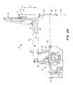
- FIG. 2Ais a side view of a robotic arm and surgical instrument assembly according to an embodiment of the invention.
- FIG. 2Bis a perspective view of the robotic arm and surgical instrument assembly of FIG. 2A;
- FIG. 3is a perspective view of a surgical instrument according to an embodiment of the invention.
- FIG. 4is a schematic kinematic diagram corresponding to the side view of the robotic arm shown in FIG. 2A, and indicates the arm having been displaced from one position into another position;
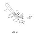
- FIG. 5is a perspective view of a preferred wrist member and end effector of the surgical instrument shown in FIG. 3, the wrist member and end effector being movably mounted on a working end of a shaft of the surgical instrument;
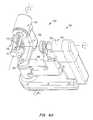
- FIG. 6Ais a perspective view of a hand held part or wrist gimbal of a master control device of the telesurgical system
- FIG. 6Bis a perspective view of an articulated arm portion of the master control device of the telesurgical system on which the wrist gimbal of FIG. 6A is mounted in use;
- FIG. 6Cis a perspective view of the master control device showing the wrist gimbal of FIG. 6A mounted on the articulated arm portion of FIG. 6B;
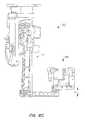
- FIGS. 6D and 6Edepict a preferred embodiment of the master control device shown in FIGS. 6A-6C having a locking mechanism for locking the slave end effector into an actuated position;
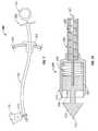
- FIG. 7is a schematic view of an aortic punch as an in vivo accessory
- FIG. 7Ais a cross-sectional view of the distal end of the aortic punch of FIG. 7;
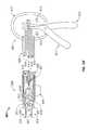
- FIG. 8is a schematic view of a cross clamp as an in vivo accessory
- FIG. 8Ais a cross-sectional view of the distal end of the cross clamp of FIG. 7;
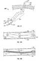
- FIG. 9is a schematic view of a conventional side-biting clamp used for partially occluding the aorta
- FIG. 10is a schematic view of two clamps provided as in vivo accessories which are arranged to partially occlude the aorta;
- FIG. 11Ais a perspective view of a foldable side-biting clamp in an extended position
- FIG. 11Bis a perspective view of the foldable side-biting clamp in a folded position
- FIG. 12is a perspective view of a stabilizer accessory
- FIGS. 12A and 12Billustrate the stabilizer accessory of FIG. 12 in a small profile configuration for insertion into an internal surgical site via a cannula;
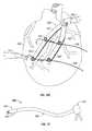
- FIG. 12Cshows the stabilizer accessory of FIG. 12 positioned over a target region of the heart to isolate a target region of a coronary artery for anastomosis;
- FIG. 13is a schematic view of a multi-fire clip applier as an in vivo accessory
- FIG. 13Ais a partial cross-sectional view illustrating the distal end and proximal end of the clip applier of FIG. 13;
- FIG. 14is a schematic view of a magnetic extraction member as an in vivo accessory
- FIG. 15is a perspective view of a pair of pliers as an in vivo accessory
- FIG. 15Ais a perspective view of a separate in vivo actuation member for engaging and actuating the pliers of FIG. 15;
- FIG. 16is a perspective view of another pair of pliers controlled by another actuation member provided as an in vivo accessory;
- FIG. 16Ais a schematic view illustrating the engagement between the actuation member and the pliers of FIG. 16;
- FIG. 16Bis a schematic view illustrating the engagement between an actuation member and pliers according to another embodiment
- FIG. 17is a perspective view of a surgical accessory support block
- FIG. 18is a perspective view of a surgical accessory container
- FIG. 19Ais a perspective view of a surgical accessory support belt in a deflated state according to another embodiment of the invention.
- FIG. 19Bis a perspective view of the surgical accessory support belt of FIG. 19A in an inflated state
- FIGS. 20A and 20Bshow perspective and end views of a modified ultrasound catheter for grasping and guidance by a robotic tool at the surgical site to collect ultrasound images of the surgical site;
- FIG. 20Cshows the modified ultrasound catheter of FIGS. 20A and 20B being manipulated by the robotic surgical system at a surgical site in an embodiment of the invention.
- end effectorrefers to the actual working part that is manipulatable for effecting a predetermined treatment of a target tissue.
- some end effectorshave a single working member such as a scalpel, a blade, or an electrode.
- Other end effectorshave a pair of working members such as forceps, graspers, scissors, or clip appliers, for example.
- the terms “surgical instrument”, “instrument”, “surgical tool”, or “tool”refer to a member having a working end which carries one or more end effectors to be introduced into a surgical site in a cavity of a patient, and is actuatable from outside the cavity to manipulate the end effector(s) for effecting a desired treatment of a target tissue in the surgical site.
- the instrument or tooltypically includes a shaft carrying the end effector(s) at a distal end, and is preferably servomechanically actuated by a telesurgical system for performing functions such as holding or driving a needle, grasping a blood vessel, and dissecting tissue.
- surgical accessoryand “accessory” refer to an assisting member that is introduced into the surgical site in the cavity of the patient to be used by an instrument or tool to perform a desired function in the surgical site.
- FIG. 1Ashows an operator station or surgeon's console 200 of a minimally invasive telesurgical system.
- the station 200includes a viewer 202 where an image of a surgical site is displayed in use.
- a support 204is provided on which an operator, typically a surgeon, can rest his or her forearms while gripping two master controls (not shown in FIG. 1 A), one in each hand.
- the master controlsare positioned in a space 206 inwardly beyond the support 204 .
- the surgeontypically sits in a chair in front of the control station 200 , positions his or her eyes in front of the viewer 202 and grips the master controls one in each hand while resting his or her forearms on the support 204 .
- FIG. 1Bshows a cart or surgical station 300 of the telesurgical system.
- the cart 300is positioned close to a patient requiring surgery and is then normally caused to remain stationary until a surgical procedure to be performed has been completed.
- the cart 300typically has wheels or castors to render it mobile.
- the station 200is typically positioned remote from the cart 300 and can be separated from the cart 300 by a great distance, even miles away, but will typically be used within an operating room with the cart 300 .
- the cart 300typically carries three robotic arm assemblies.
- One of the robotic arm assemblies, indicated by reference numeral 302is arranged to hold an image capturing device 304 , e.g., an endoscope, or the like.
- Each of the two other arm assemblies 10 respectively,includes a surgical instrument 14 .
- the endoscope 304has a viewing end 306 at a remote end of an elongate shaft thereof. It will be appreciated that the endoscope 304 has an elongate shaft to permit its viewing end 306 to be inserted through an entry port into an internal surgical site of a patient's body.
- the endoscope 304is operatively connected to the viewer 202 to display an image captured at its viewing end 306 on the viewer 202 .
- Each robotic arm assembly 10is normally operatively connected to one of the master controls.
- the instruments 14 of the robotic arm assemblies 10have end effectors that are mounted on wrist members which are pivotally mounted on distal ends of elongate shafts of the instruments 14 , as is described in greater detail below. It will be appreciated that the instruments 14 have elongate shafts to permit the end effectors to be inserted through entry ports into the internal surgical site of a patient's body. Movement of the end effectors relative to the ends of the shafts of the instruments 14 is also controlled by the master controls.
- the robotic arms 10 , 10 , 302are mounted on a carriage 97 by means of manipulator positioning linkages (“setup joint arms”) 95 .
- the carriage 97can be adjusted selectively to vary its height relative to a base 99 of the cart 300 , as indicated by arrows K.
- the setup joint arms 95are arranged to enable the lateral positions and orientations of the arms 10 , 10 , 302 to be varied relative to a vertically extending column 93 of the cart 300 . Accordingly, the positions, orientations and heights of the arms 10 , 10 , 302 can be adjusted to facilitate passing the elongate shafts of the instruments 14 and the endoscope 304 through the entry ports to desired positions relative to the surgical site.
- the setup joint arms 95 and carriage 97are typically locked in position.
- each robotic arm assembly 10includes an articulated robotic arm 12 and a surgical instrument 14 mounted thereon.
- the surgical instrument 14includes an elongate shaft 14 . 1 and a wrist-like mechanism 50 located at a working end of the shaft 14 . 1 .
- a housing 53arranged releasably to couple the instrument 14 to the robotic arm 12 , is located at an opposed end of the shaft 14 . 1 .
- the shaft 14 . 1is rotatably coupled to the housing 53 at 55 to enable angular displacement of the shaft 14 . 1 relative to the housing 53 as indicated by arrows H.
- the shaft 14 . 1extends along an axis 14 . 2 .
- the instrument 14typically is releasably mounted on a carriage 11 , which can be driven to translate along a linear guide formation 24 of the arm 12 in the direction of arrows P.
- the robotic arm 12is typically mounted on a base or platform at an end of its associated setup joint arm 95 by a bracket or mounting plate 16 .
- the robotic arm 12includes a cradle 18 , an upper arm portion 20 , a forearm portion 22 , and the guide formation 24 .
- the cradle 18is pivotally mounted on the plate 16 in a gimbaled fashion to permit rocking movement of the cradle 18 in the direction of arrows 26 about a pivot axis 28 (FIG. 2 B).
- the upper arm portion 20includes link members 30 , 32 and the forearm portion 22 includes link members 34 , 36 .
- the link members 30 , 32are pivotally mounted on the cradle 18 and are pivotally connected to the link members 34 , 36 .
- the link members 34 , 36are pivotally connected to the guide formation 24 .
- the pivotal connections between the link members 30 , 32 , 34 , 36 , the cradle 18 , and the guide formation 24are arranged to constrain the robotic arm 12 to move in a specific manner.
- the movements of the robotic arm 12are illustrated schematically in FIG. 4 .
- the solid linesschematically indicate one position of the robotic arm and the dashed lines indicate another possible position into which the arm can be displaced from the position indicated in solid lines.
- the pivot center 49normally remains in the same position relative to the stationary cart 300 on which the arm 12 is mounted.
- the pivot center 49is positioned at a port of entry into a patient's body when an internal surgical procedure is to be performed.
- the shaft 14 . 1extends through such a port of entry, the wrist-like mechanism 50 then being positioned inside the patient's body.
- the general position of the mechanism 50 relative to the surgical site in a patient's bodycan be changed by movement of the arm 12 . Since the pivot center 49 is coincident with the port of entry, such movement of the arm does not excessively effect the surrounding tissue at the port of entry.
- the robotic arm 12provides three degrees of freedom of movement to the surgical instrument 14 when mounted thereon. These degrees of freedom of movement are firstly the gimbaled motion indicated by arrows 26 , pivoting or pitching movement as indicated by arrows 27 and the linear displacement in the direction of arrows P. Movement of the arm as indicated by arrows 26 , 27 and P is controlled by appropriately positioned actuators, e.g., electrical motors or the like, which respond to inputs from its associated master control to drive the arm 12 to a desired position as dictated by movement of the master control.
- actuatorse.g., electrical motors or the like
- sensorse.g., potentiometers, encoders, or the like
- sensorsare provided on the arm and its associated setup joint arm 95 to enable a control system of the minimally invasive telesurgical system to determine joint positions, as described in greater detail below.
- sensorsas used herein is to be interpreted widely to include any appropriate sensors such as positional sensors, velocity sensors, or the like.
- the wrist-like mechanism 50includes a wrist member 52 .
- One end portion of the wrist member 52is pivotally mounted in a clevis 17 on the end 14 . 3 of the shaft 14 . 1 by means of a pivotal connection 54 .
- the wrist member 52can pivot in the direction of arrows 56 about the pivotal connection 54 .
- An end effector 58is pivotally mounted on an opposed end of the wrist member 52 .
- the end effector 58has two parts 58 . 1 , 58 . 2 together defining a jaw-like arrangement.
- the end effectorcan be in the form of any desired surgical tool, e.g., having two members or fingers which pivot relative to each other, such as a clip applier for anchoring clips, scissors, two-fingered blunt dissection tools, forceps, pliers for use as needle drivers, or the like.
- a single working membere.g., a scalpel, cautery electrode, or the like.
- the end effector 58is pivotally mounted in a clevis 19 on an opposed end of the wrist member 52 , by means of a pivotal connection 60 .
- the free ends 11 , 13 of the parts 58 . 1 , 58 . 2are angularly displaceable about the pivotal connection 60 toward and away from each other as indicated by arrows 62 , 63 .
- the members 58 . 1 , 58 . 2can be displaced angularly about the pivotal connection 60 to change the orientation of the end effector 58 as a whole, relative to the wrist member 52 .
- the end effector 58is angularly displaceable about the pivotal connection 60 independently of the other, so that the end effector 58 , as a whole, is angularly displaceable about the pivotal connection 60 as indicated in dashed lines in FIG. 5 .
- the shaft 14 . 1is rotatably mounted on the housing 53 for rotation as indicated by the arrows 59 .
- the end effector 58has three degrees of freedom of movement relative to the arm 12 in addition to actuation of the end effector members to, e.g., grip tissue, namely, rotation about the axis 14 . 2 as indicated by arrows 59 , angular displacement as a whole about the pivot 60 and angular displacement about the pivot 54 as indicated by arrows 56 .
- the end effectorBy moving the end effector within its three degrees of freedom of movement, its orientation relative to the end 14 . 3 of the shaft 14 . 1 can selectively be varied.
- preferred end effectorsare both capable of rotating and of moving independently of one another, other end effectors within the scope of the present invention might be incapable of independent movement and/or at least one end effector member might be fixed in place relative to the wrist member and/or longitudinal shaft.
- the movement of the end effector relative to the end 14 . 3 of the shaft 14 . 1is controlled by appropriately positioned actuators, e.g., electrical motors, or the like, which respond to inputs from the associated master control to drive the end effector 58 to a desired orientation as dictated by movement of the master control.
- appropriately positioned sensorse.g., encoders, or potentiometers, or the like, are provided to permit the control system of the minimally invasive telesurgical system to determine joint positions.
- FIG. 6 COne of the master controls 700 is shown in FIG. 6 C.
- a hand held part or wrist gimbal 699 of the master control device 700has an articulated arm portion including a plurality of members or links 702 connected together by pivotal connections or joints 704 .
- the surgeongrips the part 699 by positioning his or her thumb and index finger over a pincher formation 706 .
- the surgeon's thumb and index fingerare typically held on the pincher formation 706 by straps (not shown) threaded through slots 710 .
- the pincher formation 706is squeezed between the thumb and index finger, the fingers or end effector elements of the end effector 58 close.
- the joints of the part 699are operatively connected to actuators, e.g., electric motors, or the like, to provide for, e.g., force feedback, gravity compensation, and/or the like.
- actuatorse.g., electric motors, or the like
- sensorse.g., encoders, or potentiometers, or the like, are positioned on each joint 704 of the part 699 , so as to enable joint positions of the part 699 to be determined by the control system.
- the part 699is typically mounted on an articulated arm 712 as indicated in FIG. 6 B.
- Reference numeral 4 in FIGS. 6A and 6Bindicates the positions at which the part 699 and the articulated arm 712 are connected together. When connected together, the part 699 can displace angularly about an axis at 4 .
- the articulated arm 712includes a plurality of links 714 connected together at pivotal connections or joints 716 .
- the articulated arm 712further has appropriately positioned actuators, e.g., electric motors, or the like, to provide for, e.g., force feedback, gravity compensation, and/or the like.
- appropriately positioned sensorse.g., encoders, or potentiometers, or the like, are positioned on the joints 716 so as to enable joint positions of the articulated arm 712 to be determined by the control system.
- the surgeonsimply moves the pincher formation 706 to cause the end effector 58 to move to where he wants the end effector 58 to be in the image viewed in the viewer 202 .
- the end effector position and/or orientationis caused to follow that of the pincher formation 706 .
- the master control devices 700 , 700are typically mounted on the station 200 through pivotal connections at 717 as indicated in FIG. 6 B. As mentioned above, to manipulate each master control device 700 , the surgeon positions his or her thumb and index finger over the pincher formation 706 . The pincher formation 706 is positioned at a free end of the part 699 which in turn is mounted on a free end of the articulated arm portion 712 .
- the electric motors and sensors associated with the robotic arms 12 and the surgical instruments 14 mounted thereon, and the electric motors and sensors associated with the master control devices 700are operatively linked in the control system.
- the control systemtypically includes at least one processor, typically a plurality of processors, for effecting control between master control device input and responsive robotic arm and surgical instrument output and for effecting control between robotic arm and surgical instrument input and responsive master control output in the case of, e.g., force feedback.
- An example of a suitable control systemis described in U.S. application Ser. No. 09/373,678, entitled “Camera Referenced Control in a Minimally Invasive Surgical Apparatus”, filed on Aug. 13, 1999.
- the present inventionprovides ways to present a variety of accessories in vivo.
- the surgeoncan manipulate these in vivo accessories using tools already in the surgical site and adapt them for performing different functions without the need to remove the tools from the surgical site.
- the actuationcan be performed remotely from outside the patient's body while placement of the accessories takes place at the surgical site by manipulating the accessories using robotic surgical tools at the site.
- a number of examples of such in vivo accessoriesare provided herein below.
- a common procedure known as aortotomyinvolves forming an opening in the wall of an ascending aorta, and anastomosing a proximal end of a saphenous vein or the like to the opening.
- the surgeontypically makes a linear incision in the aorta with a surgical scalpel, and then passes the anvil of an aortic punch through the incision and engage the punch to create an aortotomy.
- FIG. 7shows an aortic punch 500 introduced into the surgical site in the cavity of a patient via a port through the wall 502 of the patient's body.
- a cannula sleeve 504is typically placed at the port.
- the aortic punch 500desirably is sufficiently small in cross-section so that it can be inserted through a small cannula or directly into a needle stick hole.
- the aortic punch 500desirably has a flexible body 506 including a proximal end 508 and a distal end 510 .
- the proximal end 508is disposed outside of the patient's body.
- the distal end 510has a substantially rigid portion which can be securely grasped by a grasping tool having end effectors such as forceps 110 for manipulating the distal end 510 inside the surgical site as an in vivo accessory.
- the forceps 110has two working members and is mounted on a wrist mechanism similar to the wrist mechanism 50 shown in FIGS. 3 and 5.
- the flexible body 506allows the distal end 510 to be moved freely to the desired location by manipulating effectors on the surgical tool.
- Precious time in the minimally invasive surgical procedurecan also be saved by allowing the surgeon to position the accessory with an easier-to-use robotic surgical system rather than by struggling with a less intuitive control apparatus connected to the proximal end of the accessory outside the patient's body.
- the distal end 510includes an anvil 512 movable relative to a cutter 514 .
- the cutter 514has a generally cylindrical body with a cavity which partially houses the anvil 512 .
- the anvil 512has a distal point 516 for entering a scalpel cut in the aorta.
- the anvil 512has a generally conical shape with an enlarged base 518 .
- the grasping tool 110is used to insert the anvil 512 into the scalpel cut in the aorta.
- the base 518 of the anvil 512engages a cutting edge 520 to punch or cut an opening in the aorta.
- the retraction of the anvil 512is effected remotely by pulling an actuation cable 521 that is attached to the proximal end 522 of the anvil 512 , as shown in FIG. 7 A.
- the actuation cable 521extends through the flexible body 506 to a handle 524 at the proximal end 508 of the aortic punch 500 (FIG. 7 ), so that the cable 521 is actuated from outside the patient's body.
- the flexible body 506may include a flat wound flexible support 526 inside an outer shell or jacket.
- a return spring 528is disposed in the cavity of the cutter 514 to resiliently bias the anvil 512 away from the cutter 514 . Pulling the handle 524 overcomes the biasing force of the spring 528 to perform the punching of the aorta. Upon release of the handle 524 , the spring biasing force returns the anvil 512 to the initial position away from the cutter 514 .
- the aortic punch 500 of FIGS. 7 and 7Ais particularly beneficial for use in endoscopic procedures due to its small size so that it does not take up a lot of space inside the patient's body and can be introduced into the surgical site through a small cannula or a needle stick hole apart from the main incisions or ports required for the minimally invasive robotic surgical instruments and endoscope.
- a surgeon's assistantfor example, can introduce the accessory into the patient's cavity so that the tool is ready for use by the surgeon as soon as desired.
- the aortic punch 500advantageously can be made inexpensively, and may be used as a disposable accessory. It is appreciated that aortic punches having other configurations may be used. Moreover, the aortic punch 500 may be activated using other mechanisms.
- a clamp deviceFor example, a cross clamp is used for completely occluding the aorta in a stopped heart procedure such as a stopped-heart coronary artery bypass surgery.
- a side-biting clampis typically used for occluding a part of the aorta where a proximal anastomosis is to be performed, although the use of the side-biting clamp for partially occluding the aorta can also be done in a stopped-heart procedure.
- FIG. 8shows a cross clamp 530 introduced into the surgical site in the cavity of a patient via a port through the wall 502 of the patient's body.
- the cross clamp 530can be inserted via a small cannular sleeve 504 or through a needle stick hole in the wall 502 .
- the cross clamp 530desirably has a flexible body 532 including a proximal end 534 disposed outside the patient's body, and a distal end 536 .
- the flexible body 532may include a flat wound flexible support 537 inside an outer shell (FIG. 8 A).
- the distal end 536has a substantially rigid portion which can be securely grasped by a grasping tool 110 for manipulating the distal end 536 inside the surgical site as an in vivo accessory.
- the distal end 536includes a pair of clamp jaws 538 , 540 .
- the jaw 538is stationary and the jaw 540 is movable relative to the stationary jaw 538 by an actuation cable 542 which extends through the flexible body 532 to a handle 544 at the proximal end 534 of the clamp 530 (FIG. 8 ).
- a spring 546is connected between the jaws 538 , 540 to bias them apart toward an open position.
- the grasping tool 110is used to place the jaws 538 , 540 around the aorta.
- the assistantmay pull the handle 544 remotely on the cable 542 to move the movable jaw 540 to close the clamp 530 by overcoming the spring biasing force.
- the spring 546Upon release of the handle 544 , the spring 546 returns the movable jaw 540 to the open position.
- a locking membersuch as a latch 548 is provided at the proximal end 534 of the cross clamp 530 for engaging teeth 549 on the handle 544 to locking the position of the handle 544 and cable 542 , thereby fixing the relative positions of the jaws 538 , 540 .
- the locking featureconveniently locks the jaws 538 , 540 in place after they have been positioned at the desired location and clamped around the aorta for occluding the aorta, thereby allowing the assistant to release the handle 544 and be free to perform other tasks.
- the surgeonmay release the grip of the surgical tool 110 of the clamp 530 so that the surgical tool 110 can be used for the next task in the procedure.
- clamp configurationsmay be used instead of the one illustrated in FIGS. 8 and 8A.
- some clampsare configured to have jaws that are kept in a generally parallel arrangement between open and closed positions.
- other locking mechanismsmay be used for locking the clamp 530 .
- a spring-actuated mechanismmay include a locking spring that biases the jaws together to close and lock the jaws. An operator can squeeze a trigger provided at the handle to open the jaws and place them around the aorta, and the operator can allow the spring to lock the jaws in place by releasing the trigger as desired.
- FIG. 9shows a conventional side-biting clamp 550 that is typically used for occluding a portion 551 of the aorta 552 .
- the side-biting clamp 550has a big curve for blocking off a sufficiently large portion of the aorta 552 to allow it to be punched for performing anastomosis.
- the big curve of the clamp 550is difficult to insert through a cannula, e.g., during a minimally invasive procedure.
- FIG. 10An alternative to the side-biting clamp 550 involves the use of a pair of clamps as illustrated in FIG. 10 .
- the jaws of the first clamp 556 and the jaws of the second clamp 558are overlapped or placed adjacent to each other, typically at the tips, to enclose a region 551 of the aorta 552 to be occluded.
- the jaws of the clamps 556 , 588may be bent or curved as shown in FIG. 10, but they may also be straight.
- the jaws of the clamps 556 , 558do not have the big curves as the side-biting clamp 550 of FIG. 9, so that they may be more easily inserted via cannula sleeves 504 A, 504 B through the wall 502 .
- FIG. 11AAnother approach is to use a foldable side-biting clamp 560 which can enter the surgical site via a cannula in an extended position as shown in FIG. 11A, and be arranged into a folded configuration inside the surgical site to be used as a side-biting clamp as shown in FIG. 11 B.
- the foldable clamp 560has three pairs of links or arms: proximal arms 562 A, 562 B, middle arms 564 A, 564 B, and distal arms 566 A, 566 B.
- the proximal arms 562 A, 562 Bare each connected, respectively, to the middle arms 564 A, 564 B via hinges 568 , each of which are in turn connected, respectively, to the distal arms 566 A, 566 B via hinges 570 .
- the hinges 568 , 570allow the arms to move between the extended position (FIG. 11A) and the folded position (FIG. 11 B).
- the folding of the armscan be performed using a surgical tool in the surgical site or by actuating an internal mechanism in the clamp 560 .
- proximal ends of the proximal arms 562 A, 562 Bare connected at a pivot 572 .
- the distal ends of the distal arms 566 A, 566 Bare connected at another pivot 574 .
- the three pairs of armsremain in a closed position, since the two pivots 572 , 574 are not aligned but are spaced by the three pairs of arms.
- the proximal arms 562 A, 562 B and distal arms 566 A, 566 Bare parallel to each other.
- the two pivots 572 , 574are aligned to permit pivoting of an upper jaw formed by the upper arms 562 A, 564 A, 566 A relative to the lower jaw formed by the lower arms 562 B, 564 B, 566 B.
- the pivotingcan be carried out using any suitable mechanism, such as an actuation cable arrangement similar to that illustrated in FIG. 8 A.
- the foldable clamp 560 of FIGS. 11A and 11Bdesirably includes upper and lower flexible members 576 A, 576 B made of a deformable material such as silicone rubber for providing a more secure grip of the aorta to prevent leakage.
- such occluding mechanismcan be mounted on the distal end of a robotic, remotely controlled tool, preferably having a wrist joint to increase the number of degrees of freedom of distal movement, to further facilitate placement and movement at, and interaction with, the surgical site.
- FIG. 12shows a stabilizer accessory 580 including a bifurcated structure having first and second bodies 582 , 584 coupled to each other and to an adjustable tail 586 , which is connected to a stable member or post 588 extending through the wall 502 of the patient's body.
- a proximal control member 590is coupled to the post 588 and disposed outside the patient's body.
- the tail 586is configured to be adjustable to change shape in an unlocked mode, and to be fixed in position in a locked mode by actuating the proximal control member 590 remotely after the desired shape is obtained.
- the tail 586typically includes a plurality of links that are adjustably connected in series
- An example of a tail 586is a Mediflex® arm available from Mediflex®, a division of Flexbar Machine Corporation, Islandia, N.Y.
- the Mediflex® armemploys a chain of links that can be moved freely to any shape until it is actuated (e.g., by tightening with an actuation cable connected to the proximal control member 590 ) whereupon the arm becomes locked and maintains the position and orientation for stabilizing the heart or other tissues or organs.
- Each of stabilizer bodies 582 , 584comprises an elongate plate extending distally from a pivot 592 to a distal end.
- One stabilizer body 582may be stationary, while the other stabilizer body 584 is movable relative to the stationary body 582 using an arrangement similar to that shown for the clamp in FIG. 8 A.
- a grasping toolis used to place the stabilizer bodies 582 , 584 with their tissue stabilizing surfaces 594 over a target region such as a region of the coronary artery of the heart.
- the stabilizer 580inhibits motion of the target region of the surgical worksite to allow treatment of target tissues.
- each plate 582 , 584preferably bends laterally relative to its length in the direction of its width (so that the bodies 582 , 584 cross distally of the pivot 592 when the stabilizer 580 is in a small profile configuration for insertion through a cannula 595 ) and in the direction of its thickness (as shown in FIG. 12B) so that the tissue stabilizing surfaces 594 of the bodies 582 , 584 can engage a tissue surface without interference from the pivot 592 and tail 586 .
- these multiple bendsare preferred, to facilitate better delivery through smaller cannulas and better contact with the heart's surface, these bends should not be understood to limit the scope of the present invention.
- a method for isolating a coronary artery CA downstream of an occlusion using the stabilizer 580can be understood with reference to FIG. 12C.
- a pair of flexible member 596is passed under and around the coronary artery CA using end effectors of a surgical tool 110 .
- the stabilizer 580is positioned against the heart 598 with the first and second bodies 582 , 584 of the stabilizer positioned on two sides of the coronary artery CA so as to inhibit motion of the surgical worksite.
- a target region 600 of the coronary artery CAis isolated from upstream and downstream blood flow by tensioning flexible members 596 and tying the tensioned flexible members off to anchors 602 of stabilizer 580 . Tying off the vessel in this manner not only permits isolation of the surgical site, but also can help to inhibit movement of the surgical worksite between the bodies 582 , 584 during beating-heart surgery.
- FIG. 13shows a multi-fire clip applier 605 having a body 606 with a proximal end 607 and a distal end 608 .
- the body 606is desirably flexible.
- the distal end 608may include a rigid tab 609 that can be conveniently gripped by a grasping tool for moving the distal end 608 in the surgical site.
- the flexible body 606allows the distal end 608 of the clip applier 605 to be moved freely and be placed at the desired location at the surgical site using the grasping tool disposed inside the surgical site for applying clips at the desired target location.
- the proximal end 607includes a lever housing 610 having a push lever 611 and a pull lever 612 pivotally coupled together.
- the leversare partially disposed in and are supported by the lever housing 610 .
- the lever housing 610includes lever stops 613 defining the limit of the range of movement of the levers.
- the pull lever 612is connected to a pull cable 614
- the push lever 611is connected to a push sheath 615 around the pull cable 614 .
- the cable 614 and sheath 615are disposed in the flexible body 606 .
- the distal end 608includes a clip applier housing 616 .
- a jaw squeezer 617Disposed inside the clip applier housing 616 is a jaw squeezer 617 which is connected to the push sheath 615 .
- the jaw squeezer 617is a generally cylindrical member.
- a clip feeder 618is disposed in the jaw squeezer 617 .
- the proximal end of the clip feeder 618is connected to the pull cable 614 .
- the distal end of the clip feeder 618slides between a pair of clip applier jaws 619 .
- a springbiases the jaws 619 apart.
- the jawscan slide perpendicularly to the axis of the housing.
- a spring 621 inside the jaw squeezer 617biases the clip feeder 618 to pull the jaw squeezer 617 back from the jaws 619 .
- the jaw squeezer 617forms a clip storage region for storing therein a plurality of clips 623 that can be advanced one-by-one toward the jaws 619 to be applied to a target region such as tissue.
- the jaws 619include an inclined or ramped outer surface 625 for contacting the jaw squeezer 617 .
- the push lever 611 and pull lever 612are squeezed together at the proximal end 607 , the push lever 611 moves the push sheath 615 to push the jaw squeezer 617 outward relative to the clip applier housing 616 , while the pull lever 612 pulls the pull cable 614 to pull the clip feeder 618 inward.
- the contact between the jaw squeezer 617 and the ramped surface 625 of the jaws 619cause the jaws 619 to close, thereby squeezing the clip 623 to apply the clip 623 .
- the clip feeder 618has a ramped surface 618 A that ramps up from the proximal end adjacent the pull cable 614 toward the distal end adjacent the jaws 619 , terminating at a ratchet-like catch 627 .
- the clip feeder 618As the clip feeder 618 is pulled into the jaw squeezer 617 , the next clip 623 in the jaw squeezer 617 rides on the ramped surface 618 A of the clip feeder 618 until it engages the catch 627 .
- the clip feeder 618advances clips to the jaws 619 in a ratchet-like manner.
- the jaw squeezer 617moves inward toward the clip applier housing 616 , while the clip feeder 618 moves outward away from the jaw squeezer 617 .
- the catch 627advances the next clip 623 to load it between the jaws 619 ready for application to the next target region.
- clip appliermay be applied to other similar surgical instruments such as surgical staplers (for applying staples) and tackers (for applying surgical tacks) within the scope of the present invention.
- FIG. 14shows an extractor tool 620 for extracting metallic objects such as needles or the like from the body cavity of the patient.
- the extractor tool 620desirably includes a flexible or malleable body 622 having a proximal end 624 and a distal end 626 .
- the distal end 626includes a magnetic member 628 , and is introduced into the surgical site via a port through the wall 502 of the patient's body.
- the distal end 626has a substantially rigid portion.
- the proximal end 624includes a handle 629 disposed outside the patient's body. The handle 629 can be controlled to activate the magnet 628 at the distal end 626 to form a magnetic field for attracting metallic members.
- a grasping tool 110is used to grasp the distal end 626 to maneuver it within the surgical site.
- the magnet 628 at the distal end 626may be activated remotely from outside the patient's body to attract metallic objects such as loose or dropped needles, clips, or staples, and extract them from the surgical site.
- the magnetic extractor tool 620is particularly effective in extracting objects such as needles that may be difficult to grasp with conventional grasping tools.
- the above in vivo accessoriestypically include actuation members such as actuation cables that are integral with or built into the accessories.
- the actuation member for actuating the in vivo accessoryis a separate member that is typically introduced into the surgical site via a separate port.
- FIG. 15shows an in vivo accessory including a pair of pliers 630 .
- the pliers 630include arms 632 A, 632 B at a distal end that are pivotably connected to a housing 633 to rotate about a pivot 634 in a jaw-like manner to move between open and closed positions.
- the housing 633may include grab bars 635 that can be more conveniently grasped by a grasping tool in the surgical site.
- the arms 632 A, 632 Bare each pivotally connected to a drive link 636 A, 636 B, which are coupled at a common pivot 638 on a drive nut 640 .
- the drive nut 640is threadingly coupled to a threaded shaft 642 , which is rotatably coupled to the housing 633 .
- the arms 632 A, 632 Bopen as the drive nut 640 moves down the shaft 642 toward the arms at the distal end, and close as the drive nut 640 moves up the shaft 642 .
- the movement of the drive nut 640 up and down the threaded shaft 642is produced by rotating the shaft 642 relative to the housing 633 . For instance, rotating the shaft 642 in one direction causes the drive nut 640 to move up the shaft, while rotating the shaft 642 in the opposite direction causes the drive nut 640 to move down the shaft.
- the drive nut 640 and threaded shaft 642desirably form a non-backdrivable mechanism that stays tight or fixed relative to each other until the shaft 642 is rotated.
- a docking member 644At the proximal end of the threaded shaft 642 is a docking member 644 .
- the docking member 644has a cavity 646 for receiving a rotational actuator 650 configured to rotate the shaft 642 to actuate the arms 632 A, 632 B.
- the cavity 646has a hexagonal shape, but may be shaped differently in other embodiments to form a docking cavity.
- the rotational actuator 650includes a distal drive member 652 that is configured to be inserted into the cavity 646 of the docking member 644 and to dock or mate with the docking member 644 for applying a rotational force to control movement of the arms 632 A, 632 B.
- the actuator 650is a separate in vivo accessory that is preferably introduced into the surgical site via a separate port such as a needle stick hole through a wall of the patient.
- the actuator 650may have a substantially rigid body or more desirably a flexible body that allows the distal drive member 652 to be manipulated and maneuvered more freely inside the surgical site.
- the distal drive member 652is detachably coupled to the docking member 644 , and is controlled remotely from outside the surgical site when desired to adjust the pliers 630 .
- the torque needed to rotate the actuator 650can be generated remotely from outside the patient's body.
- the distal drive member 652can be adjusted to lock onto the docking member 644 .
- the locking mechanismemploys a detent ball 654 that can be moved forward to cause the distal member 652 to expand when the distal member 652 is inserted into the cavity 646 of the docking member 644 to lock the distal member 652 with the docking member 644 .
- the detent ball 654is retracted to allow the distal member 652 to contract for removal.
- the movement of the detent ball 654may be controlled by a cable connected between the detent ball 654 and a control button at the proximal end of the actuator 650 which can be manipulated from outside the patient's body to remotely adjust the position of the detent ball 654 .
- a grasping toolis used to grasp the pliers 630 (e.g., at the grab bars 635 ) and place the arms 632 A, 632 B at the target location.
- Another grasping toolcan be used to insert the distal drive member 632 of the rotational actuator 630 into the cavity 646 of the docking member 644 for docking.
- the actuation member 650can be easily and accurately positioned in a field of view of a scope 306 for engaging and actuating the pliers 630 .
- the detent ball 654 in the actuator 650may be actuated remotely from outside the surgical site to move forward to lock the distal drive member 652 with the docking member 644 , so that the grasping tool for the distal drive member 652 can be released and used for performing the next task if desired.
- the rotational actuator 650is remotely actuated from outside the surgical site to rotate the distal drive member 652 to drive the threaded shaft 642 of the pliers 630 in rotation to move the drive nut 640 up or down the shaft 642 , thereby adjusting the positions of the arms 632 A, 632 B of the pliers 630 to perform a desired function at the target location.
- the actuator 650may be disengaged from the pliers 630 , and the grasping tool may also be detached from the pliers 630 . Disengaging the actuator 650 from the pliers 630 frees up space at the surgical site. This may be advantageous to the surgeon who may desire the surgical site to be as uncluttered as possible during a surgical procedure.
- the pliers 660have a pair of arms 662 A, 662 B that are pivotably coupled, and may include grab bars 664 .
- the proximal ends of the arms 662 A, 662 Binclude docking members 666 A, 666 B for docking an actuation member 670 .
- the actuation member 670includes a body 672 that may be rigid but is desirably flexible.
- An actuation cable or push rod 674is slidable within the body 672 .
- a distal member 676is connected to the distal end of the cable 674 .
- the distal member 676 shownis a ball, but it may be shaped different in other embodiments.
- the cable 674is actuated remotely from the proximal end of the actuation member 670 disposed outside the patient's body.
- the distal ball 676enters the cavity in the docking member 666 A from the proximal end in the direction indicated by arrow 678 .
- the docking member 666 Ahas a side slit or slot 679 for accommodating the cable 674 as the ball 676 enters the cavity.
- the other docking member 666 Bhas a cavity and a side slit or slot 680 for receiving the actuation cable 674 and the end of the body 672 in the direction indicated by arrow 681 .
- the distal ball 676is engaged with one docking member 666 A and the end of the actuation member body 672 is engaged with the other docking member 666 B, as best seen in FIG. 16 A.
- the actuation member 670is used to adjust the arms 662 A, 662 B to grip a target tissue by moving them from an open position toward a closed position.
- a lock ring 682(FIG. 16) can be slid down the arms 662 A, 662 B to lock them in place to maintain the grip.
- the actuation member 670can then be disengaged from the pliers 660 , and be available for performing the next task as desired.
- the arms 662 A, 662 Bare biased to open by a spring 684 , as shown in FIG. 16 B. Because the spring 684 applies a biasing force to open the arms, the actuation member 670 need actuate the arms in only one direction to bring them toward one another to the closed position.
- the docking members 666 A′, 666 B′ of the arms 662 A, 662 Bmay be configured differently for docking the actuation member 670 for actuating only to close the arms. As seen in FIG. 16B, the docking members 666 A′, 666 B′ may include slots to allow the actuation cable 674 to slide in for engagement.
- the actuation member body 672 and the distal ball 676are disposed on opposite sides of the docking members 666 A′, 666 B′, pulling the distal ball 676 toward the body 672 moves the arms 662 A, 662 B toward one another against the spring force.
- the actuation member 670does not apply a force on the arms, but the biasing force of the spring 684 moves the docking members 666 A′, 666 B′ apart.
- each accessorycan be connected to a cable and inserted through an opening into the surgical site and be removed from the site by pulling on the cable from outside the patient's body.
- an accessory supportcan be used to introduce a plurality of accessories into the surgical site.
- FIG. 17illustrates a surgical accessory support in the form of a block 126 for holding the accessories such as the pliers 630 , 660 .
- the block 126is introduced through the cavity wall 77 . 2 via a cannula sleeve 77 . 1 .
- the support block 126in one embodiment is made of a foam material or the like which deflects to releasably secure the accessories therein.
- the accessoriescan be removed by the grasping tool 110 inside the surgical site to perform a desired treatment and then returned to the block 126 after use.
- FIG. 18shows a container or box 130 as another embodiment of a surgical accessory support.
- the box 130extends through the cavity wall 77 . 2 via a cannula sleeve 77 . 1 .
- a handle 132supports the box 130 in the surgical site from outside the patient's cavity.
- the box 130includes a compartment 134 for housing accessories and a door 136 which can be opened to allow access to the accessories, and be closed during transportation of the box 136 into and out of the surgical site.
- a variety of mechanismscan be used to control movement of the door 136 .
- a control rod 138is connected with the door 136 and extends through the end of the handle 132 .
- the control rod 138allows the operator to open the door 136 by pushing the rod 138 toward the handle 132 and to close the door 130 by pulling the rod 138 away from the handle 132 .
- a physical or solenoid-activated latchmight be included to lock the door in an open configuration during an operation, if desired. It is appreciated that other devices can be used for introducing the surgical accessories into the surgical site and supporting them therein.
- an inflatable tool belt or support 730can be used to hold accessories 732 such as pliers, and can be inserted into the surgical site through a port with the tool belt 730 in a deflated state.
- the accessories 732may be releasably attached to the tool belt 730 in any suitable manner, such as the use of velcro or the like.
- the tool belt 730After the tool belt 730 has been inserted into the surgical site, it can be inflated in a manner similar to a balloon catheter to expose the accessories 732 so that they may be used in the surgical site, as illustrated in FIG. 19 B.
- the inflated tool belt 730provides support for the accessories 732 and may cause the accessories to stand in an erect position, making them more easily graspable by a grasping tool such as forceps 110 or the like.
- the tool belt 730can be deflated for retraction.
- a mechanism similar to those used for balloon catheterscan be used for inflating and deflating the tool belt 730 .
- FIGS. 20A and 20 bShown in FIGS. 20A and 20 b is another embodiment of an in vivo accessory within the scope of the present invention.
- Known ultrasound catheterssuch as available from Acuson of Mountain View, Calif., are available for insertion into body cavities or body lumens to image body tissues. These catheters typically have some sort of proximal control mechanism for maneuvering the distal catheter tip around the cavity or lumen to capture ultrasound images. This kind of remote control typically requires the somewhat awkward movement of multiple knobs, levers or dials to indicate the desired direction of movement of the catheter tip.
- the catheter 740 as shown in FIGS. 20A and 20Bmay simply be inserted into the thorax, for example, through a small incision or port between the ribs as an in vivo accessory, for the robotic surgeon to grasp with one or more instruments already present at the surgical site.
- the surgeonis then able to move the catheter along the vessel or tissue of interest by manipulating the robotic surgical system to move the catheter 740 , rather than either relying on an assistant to directly control movement of the ultrasound system or having to relinquish control of the robotic system to turn his attention to the ultrasound system.
- the surgeon's ability to maneuver the catheter around the surgical sitecan be improved by providing one or more tabs or grab bars 742 towards the distal end of the catheter 740 , preferably proximal of the active detector portion 744 of the ultrasound catheter 740 but within a short distance (e.g., less than about 5 cm) of the distal tip, which bars or tabs 742 can be used to facilitate grasping contact between the end effectors and the catheter 740 .
- Multiple grab bars or other grasping aidssuch as slots or end effector “gloves” mounted on the catheter 740 can be provided with different orientations, to permit the surgeon to manipulate the catheter while maintaining a comfortable orientation of the robotic system's master controls.
- Two grab bars 742are shown in FIGS. 20A and 20B.
- the simple grab bars 742comprise brass crimped around the catheter to provide a “flag” to which the end effectors can couple.
- FIG. 20Cshows an ultrasound catheter 740 being manipulated by a robotically controlled end effector 10 around a surgical site, and more specifically along a coronary artery on the surface of a patient's heart, in the manner of a preferred embodiment of the invention.
- a robotically controlled end effector 10around a surgical site, and more specifically along a coronary artery on the surface of a patient's heart, in the manner of a preferred embodiment of the invention.
- in vivo toolscan also be introduced into the body cavity and manipulated by robotic tools already in the cavity, as described throughout this application.
- irrigating tubes providing carbon dioxide or saline to the surgical site, suction devices, and blowing devicescan each be introduced to the surgical site through small accessory ports in the patient's body wall, to be manipulated at the surgical site by the end effectors of other robotic tools controlled remotely by the surgeon.
- These toolscan be actuated from outside the body cavity, either by the surgeon's assistant when requested, or by the surgeon him/herself by actuating an accessory input device such as an on/off switch operatively coupled to the accessory.
- an illumination sourcesuch as an optical fiber bundle
- a flexible camera or other imaging devicemight be introduced through a separate port to be manipulated by the surgeon at the surgical site, to provide further visual information about the patient's anatomy that is not as viewable as desired in the main endoscopic image, such as anatomy hidden from view by other anatomy or objects.
- additional visual information about hidden anatomycan be provided to the surgeon during the surgical procedure by utilizing the picture-in-picture capability described therein.
- pacing electrodescan be introduced into the heart tissue minimally invasively in this manner, as can an aortic cannulation system. No large opening is required to place these devices or achieve these results because of the dexterity provided to the surgeon directly at the surgical site, despite the surgeon's only access to the site being through small, minimally invasive ports.
Landscapes
- Health & Medical Sciences (AREA)
- Surgery (AREA)
- Life Sciences & Earth Sciences (AREA)
- Engineering & Computer Science (AREA)
- Medical Informatics (AREA)
- Nuclear Medicine, Radiotherapy & Molecular Imaging (AREA)
- Biomedical Technology (AREA)
- Heart & Thoracic Surgery (AREA)
- Molecular Biology (AREA)
- Animal Behavior & Ethology (AREA)
- General Health & Medical Sciences (AREA)
- Public Health (AREA)
- Veterinary Medicine (AREA)
- Robotics (AREA)
- Reproductive Health (AREA)
- Vascular Medicine (AREA)
- Manipulator (AREA)
Abstract
Description
Claims (42)
Priority Applications (6)
| Application Number | Priority Date | Filing Date | Title |
|---|---|---|---|
| US09/478,953US6770081B1 (en) | 2000-01-07 | 2000-01-07 | In vivo accessories for minimally invasive robotic surgery and methods |
| US10/116,504US7125403B2 (en) | 1998-12-08 | 2002-04-03 | In vivo accessories for minimally invasive robotic surgery |
| US11/522,852US7722599B2 (en) | 1998-12-08 | 2006-09-18 | In vivo accessories for minimally invasive robotic surgery |
| US12/727,060US8182476B2 (en) | 1998-12-08 | 2010-03-18 | In vivo accessories for minimally invasive robotic surgery |
| US13/454,312US8551116B2 (en) | 1998-12-08 | 2012-04-24 | In vivo accessories for minimally invasive robotic surgery |
| US14/029,592US9381067B2 (en) | 1998-12-08 | 2013-09-17 | In vivo accessories for minimally invasive surgery |
Applications Claiming Priority (1)
| Application Number | Priority Date | Filing Date | Title |
|---|---|---|---|
| US09/478,953US6770081B1 (en) | 2000-01-07 | 2000-01-07 | In vivo accessories for minimally invasive robotic surgery and methods |
Related Parent Applications (1)
| Application Number | Title | Priority Date | Filing Date |
|---|---|---|---|
| US09/453,978Continuation-In-PartUS6309397B1 (en) | 1998-12-08 | 1999-12-02 | Accessories for minimally invasive robotic surgery and methods |
Related Child Applications (1)
| Application Number | Title | Priority Date | Filing Date |
|---|---|---|---|
| US10/116,504Continuation-In-PartUS7125403B2 (en) | 1998-12-08 | 2002-04-03 | In vivo accessories for minimally invasive robotic surgery |
Publications (1)
| Publication Number | Publication Date |
|---|---|
| US6770081B1true US6770081B1 (en) | 2004-08-03 |
Family
ID=32772178
Family Applications (1)
| Application Number | Title | Priority Date | Filing Date |
|---|---|---|---|
| US09/478,953Expired - LifetimeUS6770081B1 (en) | 1998-12-08 | 2000-01-07 | In vivo accessories for minimally invasive robotic surgery and methods |
Country Status (1)
| Country | Link |
|---|---|
| US (1) | US6770081B1 (en) |
Cited By (256)
| Publication number | Priority date | Publication date | Assignee | Title |
|---|---|---|---|---|
| US20020087169A1 (en)* | 1998-02-24 | 2002-07-04 | Brock David L. | Flexible instrument |
| US20020128633A1 (en)* | 1998-02-24 | 2002-09-12 | Brock David L. | Surgical instrument |
| US20020143319A1 (en)* | 1998-02-24 | 2002-10-03 | Brock David L. | Interchangeable surgical instrument |
| US20040049205A1 (en)* | 2002-09-09 | 2004-03-11 | Endo Via Medical, Inc. | Surgical instrument coupling mechanism |
| US20050049580A1 (en)* | 2003-06-06 | 2005-03-03 | Endo Via Medical , Inc. | Surgical instrument design |
| WO2005010711A3 (en)* | 2003-07-21 | 2005-03-17 | Univ Johns Hopkins | Robotic 5-dimensional ultrasound |
| US20050283137A1 (en)* | 2004-06-16 | 2005-12-22 | Doyle Mark C | Surgical tool kit |
| US20060161137A1 (en)* | 1997-11-21 | 2006-07-20 | Intuitive Surgical Inc. | Sterile surgical drape |
| US20060235436A1 (en)* | 1996-12-12 | 2006-10-19 | Intuitive Surgical Inc. | Sterile surgical adaptor |
| US20060258938A1 (en)* | 2005-05-16 | 2006-11-16 | Intuitive Surgical Inc. | Methods and system for performing 3-D tool tracking by fusion of sensor and/or camera derived data during minimally invasive robotic surgery |
| US20070060879A1 (en)* | 2001-02-15 | 2007-03-15 | Hansen Medical, Inc. | Coaxial catheter system |
| WO2007041094A1 (en) | 2005-09-30 | 2007-04-12 | Intuitive Surgical, Inc. | Surgical accessory clamp and system |
| US20070135685A1 (en)* | 2005-12-13 | 2007-06-14 | Alfred Cuschieri | Medical Instrument And Method For Manipulating, In Particular Retracting Tissue Or An Organ |
| US20070137371A1 (en)* | 2005-12-20 | 2007-06-21 | Devengenzo Roman L | Telescoping insertion axis of a robotic surgical system |
| US20070151391A1 (en)* | 2005-12-30 | 2007-07-05 | Intultive Surgical Inc. | Modular force sensor |
| WO2007075864A1 (en) | 2005-12-20 | 2007-07-05 | Intuitive Surgical, Inc. | Instrument interface of a robotic surgical system |
| WO2007075844A1 (en) | 2005-12-20 | 2007-07-05 | Intuitive Surgical, Inc. | Telescoping insertion axis of a robotic surgical system |
| US20070232855A1 (en)* | 2002-08-14 | 2007-10-04 | Hansen Medical, Inc. | Robotic medical instrument system |
| WO2007120329A2 (en) | 2005-12-30 | 2007-10-25 | Intuitive Surgical, Inc. | Modular force sensor |
| US20070270640A1 (en)* | 2006-05-17 | 2007-11-22 | John Dimitriou | Endoscope tool coupling |
| US20070299427A1 (en)* | 2006-06-14 | 2007-12-27 | Yeung Benny H B | Surgical manipulator |
| US20080004603A1 (en)* | 2006-06-29 | 2008-01-03 | Intuitive Surgical Inc. | Tool position and identification indicator displayed in a boundary area of a computer display screen |
| US20080065109A1 (en)* | 2006-06-13 | 2008-03-13 | Intuitive Surgical, Inc. | Preventing instrument/tissue collisions |
| US20080110312A1 (en)* | 2001-08-27 | 2008-05-15 | Flow International Corporation | Apparatus for generating and manipulating a high-pressure fluid jet |
| US20080125794A1 (en)* | 1998-02-24 | 2008-05-29 | Hansen Medical, Inc. | Surgical instrument |
| US20080140088A1 (en)* | 1996-12-12 | 2008-06-12 | Intuitive Surgical, Inc. | Disposable sterile surgical adaptor |
| US20080147089A1 (en)* | 2005-12-20 | 2008-06-19 | Intuitive Surgical, Inc. | Wireless communication in a robotic surgical system |
| US20080243106A1 (en)* | 2007-03-30 | 2008-10-02 | Ethicon Endo-Surgery, Inc. | Detachable end effectors |
| US20080243141A1 (en)* | 2007-04-02 | 2008-10-02 | Salvatore Privitera | Surgical instrument with separate tool head and method of use |
| US7470268B2 (en) | 2000-07-20 | 2008-12-30 | Allegiance Corporation | Hand-actuated articulating surgical tool |
| US20090005638A1 (en)* | 2007-06-28 | 2009-01-01 | Ethicon Endo-Surgery, Inc. | Interchangeable Endoscopic End Effectors |
| US7492116B2 (en) | 2003-07-08 | 2009-02-17 | Board Of Regents Of The University Of Nebraska | Robot for surgical applications |
| US20090088772A1 (en)* | 2007-09-27 | 2009-04-02 | Blumenkranz Stephen J | Fiber optic in-situ chemical analysis in a robotic surgical system |
| US20090088634A1 (en)* | 2007-09-30 | 2009-04-02 | Intuitive Surgical, Inc. | Tool tracking systems and methods for image guided surgery |
| US20090088773A1 (en)* | 2007-09-30 | 2009-04-02 | Intuitive Surgical, Inc. | Methods of locating and tracking robotic instruments in robotic surgical systems |
| US20090088897A1 (en)* | 2007-09-30 | 2009-04-02 | Intuitive Surgical, Inc. | Methods and systems for robotic instrument tool tracking |
| WO2007113815A3 (en)* | 2006-03-30 | 2009-04-16 | Activiews Ltd | System and method for optical position measurement and guidance of a rigid or semi flexible tool to a target |
| US20090157092A1 (en)* | 2007-12-18 | 2009-06-18 | Blumenkranz Stephen J | Ribbed force sensor |
| US20090163929A1 (en)* | 2007-06-14 | 2009-06-25 | Benny Hon Bun Yeung | Surgical manipulator |
| US20090182226A1 (en)* | 2001-02-15 | 2009-07-16 | Barry Weitzner | Catheter tracking system |
| US20090192523A1 (en)* | 2006-06-29 | 2009-07-30 | Intuitive Surgical, Inc. | Synthetic representation of a surgical instrument |
| US7604642B2 (en) | 1998-02-24 | 2009-10-20 | Hansen Medical, Inc. | Interchangeable instrument |
| US20090261290A1 (en)* | 1997-09-30 | 2009-10-22 | Richard Sapienza | Environmentally benign anti-icing or deicing fluids |
| US7608083B2 (en) | 2001-02-15 | 2009-10-27 | Hansen Medical, Inc. | Robotically controlled medical instrument with a flexible section |
| US20090287223A1 (en)* | 2006-07-11 | 2009-11-19 | Eric Pua | Real-time 3-d ultrasound guidance of surgical robotics |
| US20090320637A1 (en)* | 2008-06-27 | 2009-12-31 | Allegiance Corporation | Flexible wrist-type element and methods of manufacture and use thereof |
| US20090326553A1 (en)* | 2008-06-27 | 2009-12-31 | Intuitive Surgical, Inc. | Medical robotic system providing an auxiliary view of articulatable instruments extending out of a distal end of an entry guide |
| US20090326556A1 (en)* | 2008-06-27 | 2009-12-31 | Intuitive Surgical, Inc. | Medical robotic system providing computer generated auxiliary views of a camera instrument for controlling the positioning and orienting of its tip |
| US20090326318A1 (en)* | 2008-06-27 | 2009-12-31 | Intuitive Surgical, Inc. | Medical robotic system providing an auxilary view including range of motion limitations for articulatable instruments extending out of a distal end of an entry guide |
| US7666191B2 (en) | 1996-12-12 | 2010-02-23 | Intuitive Surgical, Inc. | Robotic surgical system with sterile surgical adaptor |
| US20100069941A1 (en)* | 2008-09-15 | 2010-03-18 | Immersion Medical | Systems and Methods For Sensing Hand Motion By Measuring Remote Displacement |
| US7699835B2 (en) | 2001-02-15 | 2010-04-20 | Hansen Medical, Inc. | Robotically controlled surgical instruments |
| US7713190B2 (en) | 1998-02-24 | 2010-05-11 | Hansen Medical, Inc. | Flexible instrument |
| US7744622B2 (en) | 1999-05-10 | 2010-06-29 | Hansen Medical, Inc. | Surgical instrument |
| US7758569B2 (en) | 1998-02-24 | 2010-07-20 | Hansen Medical, Inc. | Interchangeable surgical instrument |
| US7772796B2 (en) | 2003-07-08 | 2010-08-10 | Board Of Regents Of The University Of Nebraska | Robotic devices with agent delivery components and related methods |
| US7775972B2 (en) | 1998-02-24 | 2010-08-17 | Hansen Medical, Inc. | Flexible instrument |
| US7789875B2 (en) | 1998-02-24 | 2010-09-07 | Hansen Medical, Inc. | Surgical instruments |
| US20100241136A1 (en)* | 2006-12-05 | 2010-09-23 | Mark Doyle | Instrument positioning/holding devices |
| WO2010117625A2 (en) | 2009-03-31 | 2010-10-14 | Intuitive Surgical Operations, Inc. | Optic fiber connection for a force sensing instrument |
| US20100274087A1 (en)* | 2007-06-13 | 2010-10-28 | Intuitive Surgical Operations, Inc. | Medical robotic system with coupled control modes |
| US20100286670A1 (en)* | 2004-06-16 | 2010-11-11 | Mark Doyle | Surgical tool kit |
| WO2011019878A1 (en) | 2009-08-14 | 2011-02-17 | Intuitive Surgical Operations, Inc. | Polarization and temperature insensitive surgical instrument force transducer |
| US7901399B2 (en) | 1998-02-24 | 2011-03-08 | Hansen Medical, Inc. | Interchangeable surgical instrument |
| US20110071543A1 (en)* | 2009-09-23 | 2011-03-24 | Intuitive Surgical, Inc. | Curved cannula surgical system control |
| US20110071542A1 (en)* | 2009-09-23 | 2011-03-24 | Intuitive Surgical, Inc. | Curved cannula surgical system |
| US20110087265A1 (en)* | 2009-10-09 | 2011-04-14 | Nobis Rudolph H | Laparoscopic instrument with attachable end effector |
| US20110087267A1 (en)* | 2009-10-09 | 2011-04-14 | Spivey James T | Method for exchanging end effectors in vivo |
| US20110087266A1 (en)* | 2009-10-09 | 2011-04-14 | Conlon Sean P | Loader for exchanging end effectors in vivo |
| US7960935B2 (en) | 2003-07-08 | 2011-06-14 | The Board Of Regents Of The University Of Nebraska | Robotic devices with agent delivery components and related methods |
| US20110202068A1 (en)* | 2010-02-12 | 2011-08-18 | Intuitive Surgical Operations, Inc. | Medical robotic system providing sensory feedback indicating a difference between a commanded state and a preferred pose of an articulated instrument |
| US20110218551A1 (en)* | 1996-12-12 | 2011-09-08 | Intuitive Surgical Operations, Inc. | Instrument interface of a robotic surgical system |
| US8016858B2 (en)* | 1999-06-02 | 2011-09-13 | Tyco Healthcare Group Ip | Electromechanical driver and remote surgical instrument attachment having computer assisted control capabilities |
| WO2011146018A1 (en)* | 2010-05-21 | 2011-11-24 | Biobot Surgical Pte. Ltd. | An apparatus for guiding a surgical instrument |
| US20110288560A1 (en)* | 2006-08-01 | 2011-11-24 | Shaul Shohat | System and method for telesurgery |
| US20120078290A1 (en)* | 2010-09-24 | 2012-03-29 | Nobis Rudolph H | Laparoscopic instrument with attachable end effector |
| US20120078291A1 (en)* | 2010-09-24 | 2012-03-29 | Nobis Rudolph H | Laparoscopic instrument with attachable end effector |
| US20120143212A1 (en)* | 1997-09-19 | 2012-06-07 | Massachusetts Institute Of Technology | Robotic apparatus |
| US8303576B2 (en) | 1998-02-24 | 2012-11-06 | Hansen Medical, Inc. | Interchangeable surgical instrument |
| US8343171B2 (en) | 2007-07-12 | 2013-01-01 | Board Of Regents Of The University Of Nebraska | Methods and systems of actuation in robotic devices |
| US8375808B2 (en) | 2005-12-30 | 2013-02-19 | Intuitive Surgical Operations, Inc. | Force sensing for surgical instruments |
| US8414598B2 (en) | 1998-02-24 | 2013-04-09 | Hansen Medical, Inc. | Flexible instrument |
| US8414505B1 (en) | 2001-02-15 | 2013-04-09 | Hansen Medical, Inc. | Catheter driver system |
| US8465474B2 (en) | 2009-05-19 | 2013-06-18 | Intuitive Surgical Operations, Inc. | Cleaning of a surgical instrument force sensor |
| US8636754B2 (en) | 2010-11-11 | 2014-01-28 | Atricure, Inc. | Clip applicator |
| US8679096B2 (en) | 2007-06-21 | 2014-03-25 | Board Of Regents Of The University Of Nebraska | Multifunctional operational component for robotic devices |
| US20140088638A1 (en)* | 2012-09-26 | 2014-03-27 | Ethicon Endo-Surgery, Inc. | Detachable End Effector with Lateral Lock |
| US20140135793A1 (en)* | 2012-11-14 | 2014-05-15 | Intuitive Surgical Operations, Inc. | Systems and methods for a dual control surgical instrument |
| US8852218B2 (en) | 2008-07-21 | 2014-10-07 | AtriCore, Inc. | Apparatus and methods for occluding an anatomical structure |
| US8876820B2 (en) | 2004-10-20 | 2014-11-04 | Atricure, Inc. | Surgical clamp |
| US8894633B2 (en) | 2009-12-17 | 2014-11-25 | Board Of Regents Of The University Of Nebraska | Modular and cooperative medical devices and related systems and methods |
| US8903546B2 (en) | 2009-08-15 | 2014-12-02 | Intuitive Surgical Operations, Inc. | Smooth control of an articulated instrument across areas with different work space conditions |
| US8944070B2 (en) | 1999-04-07 | 2015-02-03 | Intuitive Surgical Operations, Inc. | Non-force reflecting method for providing tool force information to a user of a telesurgical system |
| US8956377B2 (en) | 2011-06-15 | 2015-02-17 | Empire Technology Development Llc | Punch tool |
| US8968267B2 (en) | 2010-08-06 | 2015-03-03 | Board Of Regents Of The University Of Nebraska | Methods and systems for handling or delivering materials for natural orifice surgery |
| US8974440B2 (en) | 2007-08-15 | 2015-03-10 | Board Of Regents Of The University Of Nebraska | Modular and cooperative medical devices and related systems and methods |
| US9010214B2 (en) | 2012-06-22 | 2015-04-21 | Board Of Regents Of The University Of Nebraska | Local control robotic surgical devices and related methods |
| US9017349B2 (en) | 2010-10-27 | 2015-04-28 | Atricure, Inc. | Appendage clamp deployment assist device |
| US20150134114A1 (en)* | 2013-11-13 | 2015-05-14 | Panasonic Intellectual Property Management Co., Ltd. | Master apparatus for master slave apparatus, method for controlling the master apparatus, and the master slave apparatus |
| US20150157293A1 (en)* | 2013-12-09 | 2015-06-11 | Kabushiki Kaisha Toshiba | Ultrasound probe |
| US9060781B2 (en) | 2011-06-10 | 2015-06-23 | Board Of Regents Of The University Of Nebraska | Methods, systems, and devices relating to surgical end effectors |
| US9066741B2 (en) | 2010-11-01 | 2015-06-30 | Atricure, Inc. | Robotic toolkit |
| US9084623B2 (en) | 2009-08-15 | 2015-07-21 | Intuitive Surgical Operations, Inc. | Controller assisted reconfiguration of an articulated instrument during movement into and out of an entry guide |
| US9089353B2 (en) | 2011-07-11 | 2015-07-28 | Board Of Regents Of The University Of Nebraska | Robotic surgical devices, systems, and related methods |
| US9125681B2 (en) | 2012-09-26 | 2015-09-08 | Ethicon Endo-Surgery, Inc. | Detachable end effector and loader |
| US9138297B2 (en) | 2012-02-02 | 2015-09-22 | Intuitive Surgical Operations, Inc. | Systems and methods for controlling a robotic surgical system |
| US9138129B2 (en) | 2007-06-13 | 2015-09-22 | Intuitive Surgical Operations, Inc. | Method and system for moving a plurality of articulated instruments in tandem back towards an entry guide |
| US9254178B2 (en) | 2009-09-23 | 2016-02-09 | Intuitive Surgical Operations, Inc. | Curved cannula surgical system |
| US9265486B2 (en) | 2011-08-15 | 2016-02-23 | Atricure, Inc. | Surgical device |
| US9282973B2 (en) | 2012-01-20 | 2016-03-15 | Atricure, Inc. | Clip deployment tool and associated methods |
| US9370640B2 (en) | 2007-09-12 | 2016-06-21 | Novasentis, Inc. | Steerable medical guide wire device |
| US9381067B2 (en) | 1998-12-08 | 2016-07-05 | Intuitive Surgical Operations, Inc. | In vivo accessories for minimally invasive surgery |
| US9393023B2 (en) | 2009-01-13 | 2016-07-19 | Atricure, Inc. | Apparatus and methods for deploying a clip to occlude an anatomical structure |
| US9451937B2 (en) | 2013-02-27 | 2016-09-27 | Ethicon Endo-Surgery, Llc | Percutaneous instrument with collet locking mechanisms |
| US9469034B2 (en) | 2007-06-13 | 2016-10-18 | Intuitive Surgical Operations, Inc. | Method and system for switching modes of a robotic system |
| US9486189B2 (en) | 2010-12-02 | 2016-11-08 | Hitachi Aloka Medical, Ltd. | Assembly for use with surgery system |
| US9492927B2 (en) | 2009-08-15 | 2016-11-15 | Intuitive Surgical Operations, Inc. | Application of force feedback on an input device to urge its operator to command an articulated instrument to a preferred pose |
| US9498292B2 (en) | 2012-05-01 | 2016-11-22 | Board Of Regents Of The University Of Nebraska | Single site robotic device and related systems and methods |
| US9579088B2 (en) | 2007-02-20 | 2017-02-28 | Board Of Regents Of The University Of Nebraska | Methods, systems, and devices for surgical visualization and device manipulation |
| US9743987B2 (en) | 2013-03-14 | 2017-08-29 | Board Of Regents Of The University Of Nebraska | Methods, systems, and devices relating to robotic surgical devices, end effectors, and controllers |
| US9770305B2 (en) | 2012-08-08 | 2017-09-26 | Board Of Regents Of The University Of Nebraska | Robotic surgical devices, systems, and related methods |
| US9789608B2 (en) | 2006-06-29 | 2017-10-17 | Intuitive Surgical Operations, Inc. | Synthetic representation of a surgical robot |
| US9788901B2 (en) | 2010-10-08 | 2017-10-17 | Koninklijke Philips N.V. | Endoscopy-guided deployment of vessel punch |
| US9795453B2 (en) | 1996-12-12 | 2017-10-24 | Intuitive Surgical Operations, Inc. | Surgical robotic tools, data architecture, and use |
| US9814527B2 (en) | 2009-09-23 | 2017-11-14 | Intuitive Surgical Operations, Inc. | Cannula mounting fixture |
| US9833596B2 (en) | 2013-08-30 | 2017-12-05 | Novasentis, Inc. | Catheter having a steerable tip |
| US9855102B2 (en) | 2007-12-18 | 2018-01-02 | Intuitive Surgical Operations, Inc. | Force sensor temperature compensation |
| US9888966B2 (en) | 2013-03-14 | 2018-02-13 | Board Of Regents Of The University Of Nebraska | Methods, systems, and devices relating to force control surgical systems |
| US9895813B2 (en) | 2008-03-31 | 2018-02-20 | Intuitive Surgical Operations, Inc. | Force and torque sensing in a surgical robot setup arm |
| US9943375B2 (en) | 2005-12-30 | 2018-04-17 | Intuitive Surgical Operations, Inc. | Wireless force sensor on a distal portion of a surgical instrument and method |
| US9949802B2 (en) | 1996-12-12 | 2018-04-24 | Intuitive Surgical Operations, Inc. | Multi-component telepresence system and method |
| US10008017B2 (en) | 2006-06-29 | 2018-06-26 | Intuitive Surgical Operations, Inc. | Rendering tool information as graphic overlays on displayed images of tools |
| US10245069B2 (en) | 2009-09-23 | 2019-04-02 | Intuitive Surgical Operations, Inc. | Surgical port feature |
| US10251636B2 (en) | 2015-09-24 | 2019-04-09 | Ethicon Llc | Devices and methods for cleaning a surgical device |
| US10265130B2 (en) | 2015-12-11 | 2019-04-23 | Ethicon Llc | Systems, devices, and methods for coupling end effectors to surgical devices and loading devices |
| US10314565B2 (en) | 2015-08-26 | 2019-06-11 | Ethicon Llc | Surgical device having actuator biasing and locking features |
| US10335196B2 (en) | 2015-08-31 | 2019-07-02 | Ethicon Llc | Surgical instrument having a stop guard |
| US10335024B2 (en) | 2007-08-15 | 2019-07-02 | Board Of Regents Of The University Of Nebraska | Medical inflation, attachment and delivery devices and related methods |
| US10342561B2 (en) | 2014-09-12 | 2019-07-09 | Board Of Regents Of The University Of Nebraska | Quick-release end effectors and related systems and methods |
| US10376322B2 (en) | 2014-11-11 | 2019-08-13 | Board Of Regents Of The University Of Nebraska | Robotic device with compact joint design and related systems and methods |
| WO2019173294A1 (en) | 2018-03-05 | 2019-09-12 | University Of Maryland, Baltimore | Trans-esophageal aortic flow rate control |
| US10420583B2 (en) | 2013-05-22 | 2019-09-24 | Covidien Lp | Methods and apparatus for controlling surgical instruments using a port assembly |
| US10492876B2 (en) | 2012-09-17 | 2019-12-03 | Omniguide, Inc. | Devices and methods for laser surgery |
| US10507066B2 (en) | 2013-02-15 | 2019-12-17 | Intuitive Surgical Operations, Inc. | Providing information of tools by filtering image areas adjacent to or on displayed images of the tools |
| US10537402B2 (en) | 2014-11-24 | 2020-01-21 | The Board Of Regents Of The University Of Oklahoma | Surgical cleaning tool, system, and method |
| US10582973B2 (en) | 2012-08-08 | 2020-03-10 | Virtual Incision Corporation | Robotic surgical devices, systems, and related methods |
| US10591032B2 (en) | 2016-09-15 | 2020-03-17 | Intuitive Surgical Operations, Inc. | Split nut drive |
| US10653489B2 (en) | 2015-05-11 | 2020-05-19 | Covidien Lp | Coupling instrument drive unit and robotic surgical instrument |
| US10667883B2 (en) | 2013-03-15 | 2020-06-02 | Virtual Incision Corporation | Robotic surgical devices, systems, and related methods |
| US10667877B2 (en) | 2015-06-19 | 2020-06-02 | Covidien Lp | Controlling robotic surgical instruments with bidirectional coupling |
| US10675009B2 (en) | 2015-11-03 | 2020-06-09 | Ethicon Llc | Multi-head repository for use with a surgical device |
| US10702257B2 (en) | 2015-09-29 | 2020-07-07 | Ethicon Llc | Positioning device for use with surgical instruments |
| US10702347B2 (en) | 2016-08-30 | 2020-07-07 | The Regents Of The University Of California | Robotic device with compact joint design and an additional degree of freedom and related systems and methods |
| US10722319B2 (en) | 2016-12-14 | 2020-07-28 | Virtual Incision Corporation | Releasable attachment device for coupling to medical devices and related systems and methods |
| US10751136B2 (en) | 2016-05-18 | 2020-08-25 | Virtual Incision Corporation | Robotic surgical devices, systems and related methods |
| US10799306B2 (en)* | 2015-11-11 | 2020-10-13 | Intuitive Surgical Operations, Inc. | Reconfigurable end effector architecture |
| US10806538B2 (en) | 2015-08-03 | 2020-10-20 | Virtual Incision Corporation | Robotic surgical devices, systems, and related methods |
| US10857347B2 (en) | 2017-09-19 | 2020-12-08 | Pulse Biosciences, Inc. | Treatment instrument and high-voltage connectors for robotic surgical system |
| US10912543B2 (en) | 2015-11-03 | 2021-02-09 | Ethicon Llc | Surgical end effector loading device and trocar integration |
| US20210045817A1 (en)* | 2015-07-23 | 2021-02-18 | Sri International | Robotic arm and robotic surgical system |
| US10939909B2 (en) | 2012-12-13 | 2021-03-09 | Ethicon Llc | Circular needle applier with articulating and rotating shaft |
| WO2021049350A1 (en)* | 2019-09-13 | 2021-03-18 | ソニー株式会社 | Surgical tool, surgery support system, and surgical manipulation unit |
| US10966700B2 (en) | 2013-07-17 | 2021-04-06 | Virtual Incision Corporation | Robotic surgical devices, systems and related methods |
| US11013453B2 (en) | 2017-11-01 | 2021-05-25 | Board Of Trustees Of Michigan State University | Surgical tool with pressure sensor |
| US11013564B2 (en) | 2018-01-05 | 2021-05-25 | Board Of Regents Of The University Of Nebraska | Single-arm robotic device with compact joint design and related systems and methods |
| US11020193B2 (en) | 2016-09-15 | 2021-06-01 | Intuitive Surgical Operations, Inc. | Medical device drive system |
| US11039835B2 (en) | 2016-09-15 | 2021-06-22 | Intuitive Surgical Operations, Inc. | Medical device drive system |
| US11051894B2 (en) | 2017-09-27 | 2021-07-06 | Virtual Incision Corporation | Robotic surgical devices with tracking camera technology and related systems and methods |
| US11160621B2 (en) | 2017-11-17 | 2021-11-02 | Intuitive Surgical Operations, Inc. | Surgical instrument sterile adapter with optical coupler |
| US11173617B2 (en) | 2016-08-25 | 2021-11-16 | Board Of Regents Of The University Of Nebraska | Quick-release end effector tool interface |
| US11202683B2 (en) | 2019-02-22 | 2021-12-21 | Auris Health, Inc. | Surgical platform with motorized arms for adjustable arm supports |
| US11284958B2 (en) | 2016-11-29 | 2022-03-29 | Virtual Incision Corporation | User controller with user presence detection and related systems and methods |
| EP3984455A1 (en)* | 2020-10-15 | 2022-04-20 | Grifols Worldwide Operations Limited | Unit for collecting blood and/or plasma |
| US11357595B2 (en) | 2016-11-22 | 2022-06-14 | Board Of Regents Of The University Of Nebraska | Gross positioning device and related systems and methods |
| US11432895B2 (en) | 2005-12-20 | 2022-09-06 | Intuitive Surgical Operations, Inc. | Wireless communication in a robotic surgical system |
| US11432890B2 (en) | 2018-01-04 | 2022-09-06 | Covidien Lp | Systems and assemblies for mounting a surgical accessory to robotic surgical systems, and providing access therethrough |
| US11432891B2 (en) | 2015-06-03 | 2022-09-06 | Covidien Lp | Offset instrument drive unit |
| USD963851S1 (en) | 2020-07-10 | 2022-09-13 | Covidien Lp | Port apparatus |
| US11446099B2 (en) | 2016-06-03 | 2022-09-20 | Covidien Lp | Control arm for robotic surgical systems |
| US11464593B2 (en) | 2016-06-03 | 2022-10-11 | Covidien Lp | Passive axis system for robotic surgical systems |
| US11484372B2 (en) | 2019-02-15 | 2022-11-01 | Covidien Lp | Articulation mechanisms for surgical instruments such as for use in robotic surgical systems |
| US11510747B2 (en) | 2017-05-25 | 2022-11-29 | Covidien Lp | Robotic surgical systems and drapes for covering components of robotic surgical systems |
| US11517183B2 (en) | 2015-10-23 | 2022-12-06 | Covidien Lp | Surgical system for detecting gradual changes in perfusion |
| US11523509B2 (en) | 2016-05-26 | 2022-12-06 | Covidien Lp | Instrument drive units |
| US11529203B2 (en) | 2015-09-25 | 2022-12-20 | Covidien Lp | Robotic surgical assemblies and instrument drive connectors thereof |
| US11547508B2 (en) | 2016-05-26 | 2023-01-10 | Covidien Lp | Robotic surgical assemblies |
| US11553974B2 (en) | 2017-05-25 | 2023-01-17 | Covidien Lp | Systems and methods for detection of objects within a field of view of an image capture device |
| US11553984B2 (en) | 2016-06-03 | 2023-01-17 | Covidien Lp | Robotic surgical system with an embedded imager |
| US11571569B2 (en) | 2019-02-15 | 2023-02-07 | Pulse Biosciences, Inc. | High-voltage catheters for sub-microsecond pulsing |
| US11576562B2 (en) | 2016-04-07 | 2023-02-14 | Titan Medical Inc. | Camera positioning method and apparatus for capturing images during a medical procedure |
| US11576733B2 (en) | 2019-02-06 | 2023-02-14 | Covidien Lp | Robotic surgical assemblies including electrosurgical instruments having articulatable wrist assemblies |
| US11576739B2 (en) | 2018-07-03 | 2023-02-14 | Covidien Lp | Systems, methods, and computer-readable media for detecting image degradation during surgical procedures |
| US11583358B2 (en) | 2017-09-06 | 2023-02-21 | Covidien Lp | Boundary scaling of surgical robots |
| US11586106B2 (en) | 2018-12-28 | 2023-02-21 | Titan Medical Inc. | Imaging apparatus having configurable stereoscopic perspective |
| US11596489B2 (en) | 2015-03-10 | 2023-03-07 | Covidien Lp | Measuring health of a connector member of a robotic surgical system |
| US11615884B2 (en) | 2018-03-06 | 2023-03-28 | Digital Surgery Limited | Techniques for virtualized tool interaction |
| US11612446B2 (en) | 2016-06-03 | 2023-03-28 | Covidien Lp | Systems, methods, and computer-readable program products for controlling a robotically delivered manipulator |
| US11618171B2 (en) | 2013-12-11 | 2023-04-04 | Covidien Lp | Wrist and jaw assemblies for robotic surgical systems |
| US11622824B2 (en) | 2015-06-16 | 2023-04-11 | Covidien Lp | Robotic surgical system torque transduction sensing |
| US11628024B2 (en) | 2018-03-08 | 2023-04-18 | Covidien Lp | Surgical robotic systems |
| US11628022B2 (en) | 2017-09-05 | 2023-04-18 | Covidien Lp | Collision handling algorithms for robotic surgical systems |
| US11633243B2 (en) | 2018-10-10 | 2023-04-25 | Titan Medical Inc. | Instrument insertion system, method, and apparatus for performing medical procedures |
| US11647888B2 (en) | 2018-04-20 | 2023-05-16 | Covidien Lp | Compensation for observer movement in robotic surgical systems having stereoscopic displays |
| US11666395B2 (en) | 2015-06-23 | 2023-06-06 | Covidien Lp | Robotic surgical assemblies |
| US11690691B2 (en) | 2017-02-15 | 2023-07-04 | Covidien Lp | System and apparatus for crush prevention for medical robot applications |
| US11717355B2 (en) | 2019-01-29 | 2023-08-08 | Covidien Lp | Drive mechanisms for surgical instruments such as for use in robotic surgical systems |
| US11717361B2 (en) | 2017-05-24 | 2023-08-08 | Covidien Lp | Electrosurgical robotic system having tool presence detection |
| US11779413B2 (en) | 2015-11-19 | 2023-10-10 | Covidien Lp | Optical force sensor for robotic surgical system |
| US11839441B2 (en) | 2017-05-25 | 2023-12-12 | Covidien Lp | Robotic surgical system with automated guidance |
| US11883065B2 (en) | 2012-01-10 | 2024-01-30 | Board Of Regents Of The University Of Nebraska | Methods, systems, and devices for surgical access and insertion |
| US11903658B2 (en) | 2019-01-07 | 2024-02-20 | Virtual Incision Corporation | Robotically assisted surgical system and related devices and methods |
| US11925429B2 (en) | 2015-02-19 | 2024-03-12 | Covidien Lp | Repositioning method of input device for robotic surgical system |
| US11948226B2 (en) | 2021-05-28 | 2024-04-02 | Covidien Lp | Systems and methods for clinical workspace simulation |
| US11957371B2 (en) | 2014-08-13 | 2024-04-16 | Covidien Lp | Robotically controlling mechanical advantage gripping |
| US11986261B2 (en) | 2018-04-20 | 2024-05-21 | Covidien Lp | Systems and methods for surgical robotic cart placement |
| US11998212B2 (en) | 2013-11-21 | 2024-06-04 | Atricure, Inc. | Occlusion clip |
| US11998288B2 (en) | 2018-09-17 | 2024-06-04 | Covidien Lp | Surgical robotic systems |
| US12004752B2 (en) | 2012-11-21 | 2024-06-11 | Atricure, Inc. | Occlusion clip |
| US12030195B2 (en) | 2020-05-27 | 2024-07-09 | Covidien Lp | Tensioning mechanisms and methods for articulating surgical instruments such as for use in robotic surgical systems |
| US12029510B2 (en) | 2018-01-10 | 2024-07-09 | Covidien Lp | Determining positions and conditions of tools of a robotic surgical system utilizing computer vision |
| US12029523B2 (en) | 2017-12-01 | 2024-07-09 | Covidien Lp | Drape management assembly for robotic surgical systems |
| US12102403B2 (en) | 2018-02-02 | 2024-10-01 | Coviden Lp | Robotic surgical systems with user engagement monitoring |
| US12144537B2 (en) | 2017-08-16 | 2024-11-19 | Covidien Lp | End effector including wrist assembly and electrosurgical tool for robotic surgical systems |
| US12150722B2 (en) | 2020-07-06 | 2024-11-26 | Virtual Incision Corporation | Surgical robot positioning system and related devices and methods |
| US12156710B2 (en) | 2011-10-03 | 2024-12-03 | Virtual Incision Corporation | Robotic surgical devices, systems and related methods |
| US12174012B2 (en) | 2019-09-13 | 2024-12-24 | Bobst Lyon | Device for measuring a width of a slot in a product |
| US12178528B2 (en) | 2018-09-14 | 2024-12-31 | Covidien Lp | Surgical robotic systems and methods of tracking usage of surgical instruments thereof |
| US12186040B2 (en) | 2018-09-17 | 2025-01-07 | Covidien Lp | Surgical robotic systems |
| US12207894B2 (en) | 2017-09-08 | 2025-01-28 | Covidien Lp | Energy disconnect for robotic surgical assemblies |
| US12223629B2 (en) | 2019-09-11 | 2025-02-11 | Covidien Lp | Systems and methods for smoke-reduction in images |
| US12239396B2 (en) | 2008-06-27 | 2025-03-04 | Intuitive Surgical Operations, Inc. | Medical robotic system providing an auxiliary view including range of motion limitations for articulatable instruments extending out of a distal end of an entry guide |
| US12239292B2 (en)* | 2019-01-10 | 2025-03-04 | Atricure, Inc. | Clip application system and method |
| USD1066382S1 (en) | 2023-01-13 | 2025-03-11 | Covidien Lp | Display screen with graphical user interface |
| USD1066404S1 (en) | 2023-01-13 | 2025-03-11 | Covidien Lp | Display screen with graphical user interface |
| USD1066405S1 (en) | 2023-01-13 | 2025-03-11 | Covidien Lp | Display screen with graphical user interface |
| USD1066383S1 (en) | 2023-01-13 | 2025-03-11 | Covidien Lp | Display screen with graphical user interface |
| USD1066381S1 (en) | 2023-01-13 | 2025-03-11 | Covidien Lp | Display screen with graphical user interface |
| USD1066379S1 (en) | 2023-01-13 | 2025-03-11 | Covidien Lp | Display screen with graphical user interface |
| USD1066380S1 (en) | 2023-01-13 | 2025-03-11 | Covidien Lp | Display screen with graphical user interface |
| USD1066378S1 (en) | 2023-01-13 | 2025-03-11 | Covidien Lp | Display screen with graphical user interface |
| US12256890B2 (en) | 2019-12-23 | 2025-03-25 | Covidien Lp | Systems and methods for guiding surgical procedures |
| US12262964B2 (en) | 2020-02-26 | 2025-04-01 | Covidien Lp | Robotic surgical instrument including linear encoders for measuring cable displacement |
| US12266040B2 (en) | 2009-03-31 | 2025-04-01 | Intuitive Surgical Operations, Inc. | Rendering tool information as graphic overlays on displayed images of tools |
| US12262863B2 (en) | 2020-05-12 | 2025-04-01 | Covidien Lp | Systems and methods for image mapping and fusion during surgical procedures |
| US12295680B2 (en) | 2012-08-08 | 2025-05-13 | Board Of Regents Of The University Of Nebraska | Robotic surgical devices, systems and related methods |
| US12315109B2 (en) | 2019-09-11 | 2025-05-27 | Covidien Lp | Systems and methods for neural-network based color restoration |
| US12329475B2 (en) | 2016-03-04 | 2025-06-17 | Covidien Lp | Inverse kinematic control systems for robotic surgical system |
| US12350828B2 (en) | 2019-12-16 | 2025-07-08 | Covidien Lp | Surgical robotic systems including surgical instruments with articulation |
| US12357400B2 (en) | 2006-06-29 | 2025-07-15 | Intuitive Surgical Operations, Inc. | Synthetic representation of a surgical robot |
| US12369998B2 (en) | 2021-05-28 | 2025-07-29 | Covidien Lp | Real time monitoring of a robotic drive module |
| US12376934B2 (en) | 2019-05-22 | 2025-08-05 | Covidien Lp | Surgical robotic arm storage assemblies and methods of replacing surgical robotic arms using the storage assemblies |
| USD1087135S1 (en) | 2023-08-02 | 2025-08-05 | Covidien Lp | Surgeon display screen with a graphical user interface having spent staple icon |
| USD1087995S1 (en) | 2023-08-02 | 2025-08-12 | Covidien Lp | Surgeon display screen with a transitional graphical user interface having staple firing icon |
| US12390294B2 (en) | 2021-12-14 | 2025-08-19 | Covidien Lp | Robotic surgical assemblies including surgical instruments having articulatable wrist assemblies |
| US12409003B2 (en) | 2021-05-14 | 2025-09-09 | Covidien Lp | Instrument cassette assemblies for robotic surgical instruments |
| US12433699B2 (en) | 2022-02-10 | 2025-10-07 | Covidien Lp | Surgical robotic systems and robotic arm carts thereof |
Citations (13)
| Publication number | Priority date | Publication date | Assignee | Title |
|---|---|---|---|---|
| US4899730A (en) | 1987-12-11 | 1990-02-13 | Richard Wolf Gmbh | Holder for medical instruments |
| US5217003A (en)* | 1991-03-18 | 1993-06-08 | Wilk Peter J | Automated surgical system and apparatus |
| US5226429A (en)* | 1991-06-20 | 1993-07-13 | Inamed Development Co. | Laparoscopic gastric band and method |
| US5634937A (en)* | 1995-05-19 | 1997-06-03 | General Surgical Innovations, Inc. | Skin seal with inflatable membrane |
| US5762458A (en)* | 1996-02-20 | 1998-06-09 | Computer Motion, Inc. | Method and apparatus for performing minimally invasive cardiac procedures |
| US5792135A (en) | 1996-05-20 | 1998-08-11 | Intuitive Surgical, Inc. | Articulated surgical instrument for performing minimally invasive surgery with enhanced dexterity and sensitivity |
| US5797835A (en)* | 1996-09-16 | 1998-08-25 | Green; Philip S. | System and method for endosurgery employing conjoint operation of an endoscope and endosurgical instrument |
| US5797900A (en) | 1996-05-20 | 1998-08-25 | Intuitive Surgical, Inc. | Wrist mechanism for surgical instrument for performing minimally invasive surgery with enhanced dexterity and sensitivity |
| US5808665A (en)* | 1992-01-21 | 1998-09-15 | Sri International | Endoscopic surgical instrument and method for use |
| US5971976A (en)* | 1996-02-20 | 1999-10-26 | Computer Motion, Inc. | Motion minimization and compensation system for use in surgical procedures |
| US6309397B1 (en)* | 1999-12-02 | 2001-10-30 | Sri International | Accessories for minimally invasive robotic surgery and methods |
| US6325808B1 (en)* | 1998-12-08 | 2001-12-04 | Advanced Realtime Control Systems, Inc. | Robotic system, docking station, and surgical tool for collaborative control in minimally invasive surgery |
| US6409735B1 (en)* | 1997-11-14 | 2002-06-25 | Medsys S.A. | Device for positioning surgical instruments |
- 2000
- 2000-01-07USUS09/478,953patent/US6770081B1/ennot_activeExpired - Lifetime
Patent Citations (13)
| Publication number | Priority date | Publication date | Assignee | Title |
|---|---|---|---|---|
| US4899730A (en) | 1987-12-11 | 1990-02-13 | Richard Wolf Gmbh | Holder for medical instruments |
| US5217003A (en)* | 1991-03-18 | 1993-06-08 | Wilk Peter J | Automated surgical system and apparatus |
| US5226429A (en)* | 1991-06-20 | 1993-07-13 | Inamed Development Co. | Laparoscopic gastric band and method |
| US5808665A (en)* | 1992-01-21 | 1998-09-15 | Sri International | Endoscopic surgical instrument and method for use |
| US5634937A (en)* | 1995-05-19 | 1997-06-03 | General Surgical Innovations, Inc. | Skin seal with inflatable membrane |
| US5971976A (en)* | 1996-02-20 | 1999-10-26 | Computer Motion, Inc. | Motion minimization and compensation system for use in surgical procedures |
| US5762458A (en)* | 1996-02-20 | 1998-06-09 | Computer Motion, Inc. | Method and apparatus for performing minimally invasive cardiac procedures |
| US5797900A (en) | 1996-05-20 | 1998-08-25 | Intuitive Surgical, Inc. | Wrist mechanism for surgical instrument for performing minimally invasive surgery with enhanced dexterity and sensitivity |
| US5792135A (en) | 1996-05-20 | 1998-08-11 | Intuitive Surgical, Inc. | Articulated surgical instrument for performing minimally invasive surgery with enhanced dexterity and sensitivity |
| US5797835A (en)* | 1996-09-16 | 1998-08-25 | Green; Philip S. | System and method for endosurgery employing conjoint operation of an endoscope and endosurgical instrument |
| US6409735B1 (en)* | 1997-11-14 | 2002-06-25 | Medsys S.A. | Device for positioning surgical instruments |
| US6325808B1 (en)* | 1998-12-08 | 2001-12-04 | Advanced Realtime Control Systems, Inc. | Robotic system, docking station, and surgical tool for collaborative control in minimally invasive surgery |
| US6309397B1 (en)* | 1999-12-02 | 2001-10-30 | Sri International | Accessories for minimally invasive robotic surgery and methods |
Cited By (526)
| Publication number | Priority date | Publication date | Assignee | Title |
|---|---|---|---|---|
| US20060235436A1 (en)* | 1996-12-12 | 2006-10-19 | Intuitive Surgical Inc. | Sterile surgical adaptor |
| US20100174293A1 (en)* | 1996-12-12 | 2010-07-08 | Intuitive Surgical, Inc. | Sterile surgical adaptor |
| US9795453B2 (en) | 1996-12-12 | 2017-10-24 | Intuitive Surgical Operations, Inc. | Surgical robotic tools, data architecture, and use |
| US20080140088A1 (en)* | 1996-12-12 | 2008-06-12 | Intuitive Surgical, Inc. | Disposable sterile surgical adaptor |
| US7666191B2 (en) | 1996-12-12 | 2010-02-23 | Intuitive Surgical, Inc. | Robotic surgical system with sterile surgical adaptor |
| US8216250B2 (en) | 1996-12-12 | 2012-07-10 | Intuitive Surgical Operations, Inc. | Sterile surgical adaptor |
| US8206406B2 (en) | 1996-12-12 | 2012-06-26 | Intuitive Surgical Operations, Inc. | Disposable sterile surgical adaptor |
| US7699855B2 (en) | 1996-12-12 | 2010-04-20 | Intuitive Surgical Operations, Inc. | Sterile surgical adaptor |
| US7963913B2 (en) | 1996-12-12 | 2011-06-21 | Intuitive Surgical Operations, Inc. | Instrument interface of a robotic surgical system |
| US8529582B2 (en) | 1996-12-12 | 2013-09-10 | Intuitive Surgical Operations, Inc. | Instrument interface of a robotic surgical system |
| US9724163B2 (en) | 1996-12-12 | 2017-08-08 | Intuitive Surgical Operations, Inc. | Disposable sterile surgical adaptor |
| US9949802B2 (en) | 1996-12-12 | 2018-04-24 | Intuitive Surgical Operations, Inc. | Multi-component telepresence system and method |
| US20100163057A1 (en)* | 1996-12-12 | 2010-07-01 | Intuitive Surgical, Inc. | Sterile surgical adaptor |
| US9439732B2 (en) | 1996-12-12 | 2016-09-13 | Intuitive Surgical Operations, Inc. | Instrument interface of a robotic surgical system |
| US8105338B2 (en) | 1996-12-12 | 2012-01-31 | Intuitive Surgical Operations, Inc. | Sterile surgical adaptor |
| US8998799B2 (en) | 1996-12-12 | 2015-04-07 | Intuitive Surgical Operations, Inc. | Sterile surgical adaptor |
| US20110218551A1 (en)* | 1996-12-12 | 2011-09-08 | Intuitive Surgical Operations, Inc. | Instrument interface of a robotic surgical system |
| US20120143212A1 (en)* | 1997-09-19 | 2012-06-07 | Massachusetts Institute Of Technology | Robotic apparatus |
| US20090261290A1 (en)* | 1997-09-30 | 2009-10-22 | Richard Sapienza | Environmentally benign anti-icing or deicing fluids |
| US8182469B2 (en) | 1997-11-21 | 2012-05-22 | Intuitive Surgical Operations, Inc. | Surgical accessory clamp and method |
| US9320568B2 (en) | 1997-11-21 | 2016-04-26 | Intuitive Surgical Operations, Inc. | Sterile surgical drape |
| US20060161137A1 (en)* | 1997-11-21 | 2006-07-20 | Intuitive Surgical Inc. | Sterile surgical drape |
| US7727244B2 (en) | 1997-11-21 | 2010-06-01 | Intuitive Surgical Operation, Inc. | Sterile surgical drape |
| US8202278B2 (en) | 1997-11-21 | 2012-06-19 | Intuitive Surgical Operations, Inc. | Sterile surgical drape |
| US20100200002A1 (en)* | 1997-11-21 | 2010-08-12 | Intuitive Surgical Operations, Inc. | Sterile surgical drape |
| US9532849B2 (en) | 1997-11-21 | 2017-01-03 | Intuitive Surgical Operations, Inc. | Surgical accessory clamp and system |
| US7867241B2 (en) | 1998-02-24 | 2011-01-11 | Hansen Medical, Inc. | Flexible instrument |
| US7905828B2 (en) | 1998-02-24 | 2011-03-15 | Hansen Medical, Inc. | Flexible instrument |
| US7297142B2 (en) | 1998-02-24 | 2007-11-20 | Hansen Medical, Inc. | Interchangeable surgical instrument |
| US7789875B2 (en) | 1998-02-24 | 2010-09-07 | Hansen Medical, Inc. | Surgical instruments |
| US7775972B2 (en) | 1998-02-24 | 2010-08-17 | Hansen Medical, Inc. | Flexible instrument |
| US7901399B2 (en) | 1998-02-24 | 2011-03-08 | Hansen Medical, Inc. | Interchangeable surgical instrument |
| US7758569B2 (en) | 1998-02-24 | 2010-07-20 | Hansen Medical, Inc. | Interchangeable surgical instrument |
| US7214230B2 (en) | 1998-02-24 | 2007-05-08 | Hansen Medical, Inc. | Flexible instrument |
| US7371210B2 (en) | 1998-02-24 | 2008-05-13 | Hansen Medical, Inc. | Flexible instrument |
| US8114097B2 (en) | 1998-02-24 | 2012-02-14 | Hansen Medical, Inc. | Flexible instrument |
| US20080125794A1 (en)* | 1998-02-24 | 2008-05-29 | Hansen Medical, Inc. | Surgical instrument |
| US7931586B2 (en) | 1998-02-24 | 2011-04-26 | Hansen Medical, Inc. | Flexible instrument |
| US20020087169A1 (en)* | 1998-02-24 | 2002-07-04 | Brock David L. | Flexible instrument |
| US7713190B2 (en) | 1998-02-24 | 2010-05-11 | Hansen Medical, Inc. | Flexible instrument |
| US7918861B2 (en) | 1998-02-24 | 2011-04-05 | Hansen Medical, Inc. | Flexible instrument |
| US8303576B2 (en) | 1998-02-24 | 2012-11-06 | Hansen Medical, Inc. | Interchangeable surgical instrument |
| US8414598B2 (en) | 1998-02-24 | 2013-04-09 | Hansen Medical, Inc. | Flexible instrument |
| US20020143319A1 (en)* | 1998-02-24 | 2002-10-03 | Brock David L. | Interchangeable surgical instrument |
| US20020128633A1 (en)* | 1998-02-24 | 2002-09-12 | Brock David L. | Surgical instrument |
| US7604642B2 (en) | 1998-02-24 | 2009-10-20 | Hansen Medical, Inc. | Interchangeable instrument |
| US9381067B2 (en) | 1998-12-08 | 2016-07-05 | Intuitive Surgical Operations, Inc. | In vivo accessories for minimally invasive surgery |
| US9101397B2 (en) | 1999-04-07 | 2015-08-11 | Intuitive Surgical Operations, Inc. | Real-time generation of three-dimensional ultrasound image using a two-dimensional ultrasound transducer in a robotic system |
| US10271909B2 (en) | 1999-04-07 | 2019-04-30 | Intuitive Surgical Operations, Inc. | Display of computer generated image of an out-of-view portion of a medical device adjacent a real-time image of an in-view portion of the medical device |
| US8944070B2 (en) | 1999-04-07 | 2015-02-03 | Intuitive Surgical Operations, Inc. | Non-force reflecting method for providing tool force information to a user of a telesurgical system |
| US10433919B2 (en) | 1999-04-07 | 2019-10-08 | Intuitive Surgical Operations, Inc. | Non-force reflecting method for providing tool force information to a user of a telesurgical system |
| US9232984B2 (en) | 1999-04-07 | 2016-01-12 | Intuitive Surgical Operations, Inc. | Real-time generation of three-dimensional ultrasound image using a two-dimensional ultrasound transducer in a robotic system |
| US7744622B2 (en) | 1999-05-10 | 2010-06-29 | Hansen Medical, Inc. | Surgical instrument |
| US9782172B2 (en) | 1999-06-02 | 2017-10-10 | Covidien Lp | Electromechanical drive and remote surgical instrument attachment having computer assisted control capabilities |
| US8690913B2 (en) | 1999-06-02 | 2014-04-08 | Covidien Lp | Electromechanical drive and remote surgical instrument attachment having computer assisted control capabilities |
| US8016858B2 (en)* | 1999-06-02 | 2011-09-13 | Tyco Healthcare Group Ip | Electromechanical driver and remote surgical instrument attachment having computer assisted control capabilities |
| US9241716B2 (en) | 1999-06-02 | 2016-01-26 | Covidien Lp | Electromechanical drive and remote surgical instrument attachment having computer assisted control capabilities |
| US9662109B2 (en) | 1999-06-02 | 2017-05-30 | Covidien Lp | Electromechanical drive and remote surgical instrument attachment having computer assisted control capabilities |
| US8105319B2 (en) | 2000-07-20 | 2012-01-31 | Carefusion 2200, Inc. | Hand-actuated articulating surgical tool |
| US7470268B2 (en) | 2000-07-20 | 2008-12-30 | Allegiance Corporation | Hand-actuated articulating surgical tool |
| US7744608B2 (en) | 2001-02-15 | 2010-06-29 | Hansen Medical, Inc. | Robotically controlled medical instrument |
| US7608083B2 (en) | 2001-02-15 | 2009-10-27 | Hansen Medical, Inc. | Robotically controlled medical instrument with a flexible section |
| US8187229B2 (en) | 2001-02-15 | 2012-05-29 | Hansen Medical, Inc. | Coaxial catheter system |
| US20090182226A1 (en)* | 2001-02-15 | 2009-07-16 | Barry Weitzner | Catheter tracking system |
| US20090105639A1 (en)* | 2001-02-15 | 2009-04-23 | Hansen Medical, Inc. | Catheter driver system |
| US7699835B2 (en) | 2001-02-15 | 2010-04-20 | Hansen Medical, Inc. | Robotically controlled surgical instruments |
| US10695536B2 (en) | 2001-02-15 | 2020-06-30 | Auris Health, Inc. | Catheter driver system |
| US7955316B2 (en) | 2001-02-15 | 2011-06-07 | Han Sen Medical, Inc. | Coaxial catheter system |
| US8603068B2 (en) | 2001-02-15 | 2013-12-10 | Hansen Medical Inc. | Coaxial catheter system |
| US8684952B2 (en) | 2001-02-15 | 2014-04-01 | Hansen Medical, Inc. | Catheter driver system |
| US7727185B2 (en) | 2001-02-15 | 2010-06-01 | Hansen Medical, Inc. | Coaxial catheter system |
| US7819884B2 (en) | 2001-02-15 | 2010-10-26 | Hansen Medical, Inc. | Robotically controlled medical instrument |
| US8414505B1 (en) | 2001-02-15 | 2013-04-09 | Hansen Medical, Inc. | Catheter driver system |
| US7854738B2 (en) | 2001-02-15 | 2010-12-21 | Hansen Medical, Inc. | Robotically controlled medical instrument |
| US20070060879A1 (en)* | 2001-02-15 | 2007-03-15 | Hansen Medical, Inc. | Coaxial catheter system |
| US7766894B2 (en) | 2001-02-15 | 2010-08-03 | Hansen Medical, Inc. | Coaxial catheter system |
| US20080110312A1 (en)* | 2001-08-27 | 2008-05-15 | Flow International Corporation | Apparatus for generating and manipulating a high-pressure fluid jet |
| US7703363B2 (en)* | 2001-08-27 | 2010-04-27 | Flow International Corporation | Apparatus for generating and manipulating a high-pressure fluid jet |
| US20070239186A1 (en)* | 2002-08-14 | 2007-10-11 | Hansen Medical, Inc. | Robotic medical instrument system |
| US8671950B2 (en) | 2002-08-14 | 2014-03-18 | Hansen Medical, Inc. | Robotic medical instrument system |
| US20070238924A1 (en)* | 2002-08-14 | 2007-10-11 | Hansen Medical, Inc. | Robotic medical instrument system |
| US20070232855A1 (en)* | 2002-08-14 | 2007-10-04 | Hansen Medical, Inc. | Robotic medical instrument system |
| US20070250072A1 (en)* | 2002-08-14 | 2007-10-25 | Hansen Medical, Inc. | Robotic medical instrument system |
| US7959557B2 (en) | 2002-08-14 | 2011-06-14 | Hansen Medical, Inc. | Robotic medical instrument system |
| US7947050B2 (en) | 2002-09-09 | 2011-05-24 | Hansen Medical, Inc. | Surgical instrument coupling mechanism |
| US7331967B2 (en) | 2002-09-09 | 2008-02-19 | Hansen Medical, Inc. | Surgical instrument coupling mechanism |
| US20070238925A1 (en)* | 2002-09-09 | 2007-10-11 | Hansen Medical, Inc | Surgical instrument coupling mechanism |
| US20040049205A1 (en)* | 2002-09-09 | 2004-03-11 | Endo Via Medical, Inc. | Surgical instrument coupling mechanism |
| US20070239172A1 (en)* | 2002-09-09 | 2007-10-11 | Hansen Medical, Inc. | Surgical instrument coupling mechanism |
| US7947051B2 (en) | 2002-09-09 | 2011-05-24 | Hansen Medical, Inc. | Surgical instrument coupling mechanism |
| US8007511B2 (en) | 2003-06-06 | 2011-08-30 | Hansen Medical, Inc. | Surgical instrument design |
| US20050049580A1 (en)* | 2003-06-06 | 2005-03-03 | Endo Via Medical , Inc. | Surgical instrument design |
| US7960935B2 (en) | 2003-07-08 | 2011-06-14 | The Board Of Regents Of The University Of Nebraska | Robotic devices with agent delivery components and related methods |
| US7772796B2 (en) | 2003-07-08 | 2010-08-10 | Board Of Regents Of The University Of Nebraska | Robotic devices with agent delivery components and related methods |
| US9403281B2 (en) | 2003-07-08 | 2016-08-02 | Board Of Regents Of The University Of Nebraska | Robotic devices with arms and related methods |
| US8604742B2 (en) | 2003-07-08 | 2013-12-10 | Board Of Regents Of The University Of Nebraska | Robotic devices with arms and related methods |
| US7492116B2 (en) | 2003-07-08 | 2009-02-17 | Board Of Regents Of The University Of Nebraska | Robot for surgical applications |
| WO2005010711A3 (en)* | 2003-07-21 | 2005-03-17 | Univ Johns Hopkins | Robotic 5-dimensional ultrasound |
| US7241290B2 (en) | 2004-06-16 | 2007-07-10 | Kinetic Surgical, Llc | Surgical tool kit |
| US20050283137A1 (en)* | 2004-06-16 | 2005-12-22 | Doyle Mark C | Surgical tool kit |
| US20100286670A1 (en)* | 2004-06-16 | 2010-11-11 | Mark Doyle | Surgical tool kit |
| US8353897B2 (en) | 2004-06-16 | 2013-01-15 | Carefusion 2200, Inc. | Surgical tool kit |
| US8021358B2 (en) | 2004-06-16 | 2011-09-20 | Carefusion 2200, Inc. | Surgical tool kit |
| US8876820B2 (en) | 2004-10-20 | 2014-11-04 | Atricure, Inc. | Surgical clamp |
| US10620066B2 (en) | 2005-03-30 | 2020-04-14 | Intuitive Surgical Operations, Inc. | Ribbed force sensor |
| US9192448B2 (en) | 2005-03-30 | 2015-11-24 | Intuitive Surgical Operations, Inc. | Cleaning of a surgical instrument force sensor |
| US9339347B2 (en) | 2005-03-30 | 2016-05-17 | Intuitive Surgical Operations, Inc. | Optic fiber connection for a force sensing instrument |
| US9649172B2 (en) | 2005-03-30 | 2017-05-16 | Intuitive Surgical Operations, Inc. | Optic fiber connection for a force sensing instrument |
| US9883920B2 (en) | 2005-03-30 | 2018-02-06 | Intuitive Surgical Operations, Inc. | Cleaning of a surgical instrument force sensor |
| US9055962B2 (en) | 2005-03-30 | 2015-06-16 | Intuitive Surgical Operations, Inc. | Optic fiber connection for a force sensing instrument |
| US11478308B2 (en) | 2005-05-16 | 2022-10-25 | Intuitive Surgical Operations, Inc. | Methods and system for performing 3-D tool tracking by fusion of sensor and/or camera derived data during minimally invasive robotic surgery |
| US10555775B2 (en) | 2005-05-16 | 2020-02-11 | Intuitive Surgical Operations, Inc. | Methods and system for performing 3-D tool tracking by fusion of sensor and/or camera derived data during minimally invasive robotic surgery |
| US20060258938A1 (en)* | 2005-05-16 | 2006-11-16 | Intuitive Surgical Inc. | Methods and system for performing 3-D tool tracking by fusion of sensor and/or camera derived data during minimally invasive robotic surgery |
| US10792107B2 (en) | 2005-05-16 | 2020-10-06 | Intuitive Surgical Operations, Inc. | Methods and system for performing 3-D tool tracking by fusion of sensor and/or camera derived data during minimally invasive robotic surgery |
| US11672606B2 (en) | 2005-05-16 | 2023-06-13 | Intuitive Surgical Operations, Inc. | Methods and system for performing 3-D tool tracking by fusion of sensor and/or camera derived data during minimally invasive robotic surgery |
| US10842571B2 (en) | 2005-05-16 | 2020-11-24 | Intuitive Surgical Operations, Inc. | Methods and system for performing 3-D tool tracking by fusion of sensor and/or camera derived data during minimally invasive robotic surgery |
| US11116578B2 (en) | 2005-05-16 | 2021-09-14 | Intuitive Surgical Operations, Inc. | Methods and system for performing 3-D tool tracking by fusion of sensor and/or camera derived data during minimally invasive robotic surgery |
| EP3111876A2 (en) | 2005-09-30 | 2017-01-04 | Intuitive Surgical Operations, Inc. | Surgical accessory clamp and system |
| EP2559396A2 (en) | 2005-09-30 | 2013-02-20 | Intuitive Surgical Operations, Inc. | Sterile surgical drape |
| WO2007041094A1 (en) | 2005-09-30 | 2007-04-12 | Intuitive Surgical, Inc. | Surgical accessory clamp and system |
| EP3639784A1 (en) | 2005-09-30 | 2020-04-22 | Intuitive Surgical Operations, Inc. | Sterile surgical drape |
| EP2335635A1 (en) | 2005-09-30 | 2011-06-22 | Intuitive Surgical Operations, Inc. | Surgical accessory clamp and system |
| EP3590459A1 (en) | 2005-09-30 | 2020-01-08 | Intuitive Surgical Operations Inc. | Surgical accessory clamp and system |
| WO2007041093A1 (en) | 2005-09-30 | 2007-04-12 | Intuitive Surgical, Inc. | Sterile surgical drape |
| US20070135685A1 (en)* | 2005-12-13 | 2007-06-14 | Alfred Cuschieri | Medical Instrument And Method For Manipulating, In Particular Retracting Tissue Or An Organ |
| EP1797823A1 (en)* | 2005-12-13 | 2007-06-20 | University of Dundee | Medical instrument and method for manipulating, in particular retracting tissue or an organ |
| US8333695B2 (en) | 2005-12-13 | 2012-12-18 | University Of Dundee | Medical instrument and method for manipulating, in particular retracting tissue or an organ |
| WO2007075844A1 (en) | 2005-12-20 | 2007-07-05 | Intuitive Surgical, Inc. | Telescoping insertion axis of a robotic surgical system |
| US10182876B2 (en) | 2005-12-20 | 2019-01-22 | Intuitibe Surgical Operations, Inc. | Cable tensioning in a robotic surgical system |
| US8182470B2 (en) | 2005-12-20 | 2012-05-22 | Intuitive Surgical Operations, Inc. | Telescoping insertion axis of a robotic surgical system |
| DE102006059165B4 (en)* | 2005-12-20 | 2014-09-04 | Intuitive Surgical, Inc. | Sterile surgical adapter and coupling procedure |
| US9480533B2 (en) | 2005-12-20 | 2016-11-01 | Intuitive Surgical Operations, Inc. | Telescoping insertion axis of a robotic surgical system |
| US9486288B2 (en) | 2005-12-20 | 2016-11-08 | Intuitive Surgical Operations, Inc. | Cable tensioning in a robotic surgical system |
| US7955322B2 (en) | 2005-12-20 | 2011-06-07 | Intuitive Surgical Operations, Inc. | Wireless communication in a robotic surgical system |
| US8888764B2 (en) | 2005-12-20 | 2014-11-18 | Intuitive Surgical Operations, Inc. | Wireless communication in a robotic surgical system |
| US11432895B2 (en) | 2005-12-20 | 2022-09-06 | Intuitive Surgical Operations, Inc. | Wireless communication in a robotic surgical system |
| US20070137371A1 (en)* | 2005-12-20 | 2007-06-21 | Devengenzo Roman L | Telescoping insertion axis of a robotic surgical system |
| US8672922B2 (en) | 2005-12-20 | 2014-03-18 | Intuitive Surgical Operations, Inc. | Wireless communication in a robotic surgical system |
| WO2007075864A1 (en) | 2005-12-20 | 2007-07-05 | Intuitive Surgical, Inc. | Instrument interface of a robotic surgical system |
| US8998930B2 (en) | 2005-12-20 | 2015-04-07 | Intuitive Surgical Operations, Inc. | Disposable sterile surgical adaptor |
| US8641700B2 (en) | 2005-12-20 | 2014-02-04 | Intuitive Surgical Operations, Inc. | Telescoping insertion axis of a robotic surgical system |
| US9050119B2 (en) | 2005-12-20 | 2015-06-09 | Intuitive Surgical Operations, Inc. | Cable tensioning in a robotic surgical system |
| US10342625B2 (en) | 2005-12-20 | 2019-07-09 | Intuitive Surgical Operations, Inc. | Wireless communication in a robotic surgical system |
| US20080147089A1 (en)* | 2005-12-20 | 2008-06-19 | Intuitive Surgical, Inc. | Wireless communication in a robotic surgical system |
| US12285232B2 (en) | 2005-12-20 | 2025-04-29 | Intuitive Surgical Operations, Inc. | Cable tensioning in a robotic surgical system |
| US8469947B2 (en) | 2005-12-20 | 2013-06-25 | Intuitive Surgical Operations, Inc. | Wireless communication in a robotic surgical system |
| US9943375B2 (en) | 2005-12-30 | 2018-04-17 | Intuitive Surgical Operations, Inc. | Wireless force sensor on a distal portion of a surgical instrument and method |
| US7752920B2 (en) | 2005-12-30 | 2010-07-13 | Intuitive Surgical Operations, Inc. | Modular force sensor |
| US8281670B2 (en) | 2005-12-30 | 2012-10-09 | Intuitive Surgical Operations, Inc. | Modular force sensor |
| US20070151391A1 (en)* | 2005-12-30 | 2007-07-05 | Intultive Surgical Inc. | Modular force sensor |
| WO2007120329A2 (en) | 2005-12-30 | 2007-10-25 | Intuitive Surgical, Inc. | Modular force sensor |
| EP2289455A2 (en) | 2005-12-30 | 2011-03-02 | Intuitive Surgical Operations, Inc. | Modular force sensor |
| US8613230B2 (en) | 2005-12-30 | 2013-12-24 | Intuitive Surgical Operations, Inc. | Force sensing for surgical instruments |
| US10363107B2 (en) | 2005-12-30 | 2019-07-30 | Intuitive Surgical Operations, Inc. | Wireless force sensor on a distal portion of a surgical instrument and method |
| US8375808B2 (en) | 2005-12-30 | 2013-02-19 | Intuitive Surgical Operations, Inc. | Force sensing for surgical instruments |
| US10905502B2 (en) | 2005-12-30 | 2021-02-02 | Intuitive Surgical Operations, Inc. | Wireless force sensor on a distal portion of a surgical instrument and method |
| WO2007113815A3 (en)* | 2006-03-30 | 2009-04-16 | Activiews Ltd | System and method for optical position measurement and guidance of a rigid or semi flexible tool to a target |
| US20070270640A1 (en)* | 2006-05-17 | 2007-11-22 | John Dimitriou | Endoscope tool coupling |
| US7927271B2 (en) | 2006-05-17 | 2011-04-19 | C.R. Bard, Inc. | Endoscope tool coupling |
| US9345387B2 (en) | 2006-06-13 | 2016-05-24 | Intuitive Surgical Operations, Inc. | Preventing instrument/tissue collisions |
| US20080065109A1 (en)* | 2006-06-13 | 2008-03-13 | Intuitive Surgical, Inc. | Preventing instrument/tissue collisions |
| US20070299427A1 (en)* | 2006-06-14 | 2007-12-27 | Yeung Benny H B | Surgical manipulator |
| US8491603B2 (en) | 2006-06-14 | 2013-07-23 | MacDonald Dettwiller and Associates Inc. | Surgical manipulator |
| US10376323B2 (en) | 2006-06-22 | 2019-08-13 | Board Of Regents Of The University Of Nebraska | Multifunctional operational component for robotic devices |
| US8834488B2 (en) | 2006-06-22 | 2014-09-16 | Board Of Regents Of The University Of Nebraska | Magnetically coupleable robotic surgical devices and related methods |
| US10307199B2 (en) | 2006-06-22 | 2019-06-04 | Board Of Regents Of The University Of Nebraska | Robotic surgical devices and related methods |
| US10959790B2 (en) | 2006-06-22 | 2021-03-30 | Board Of Regents Of The University Of Nebraska | Multifunctional operational component for robotic devices |
| US8968332B2 (en) | 2006-06-22 | 2015-03-03 | Board Of Regents Of The University Of Nebraska | Magnetically coupleable robotic surgical devices and related methods |
| US10137575B2 (en) | 2006-06-29 | 2018-11-27 | Intuitive Surgical Operations, Inc. | Synthetic representation of a surgical robot |
| US12357400B2 (en) | 2006-06-29 | 2025-07-15 | Intuitive Surgical Operations, Inc. | Synthetic representation of a surgical robot |
| US10773388B2 (en) | 2006-06-29 | 2020-09-15 | Intuitive Surgical Operations, Inc. | Tool position and identification indicator displayed in a boundary area of a computer display screen |
| US10737394B2 (en) | 2006-06-29 | 2020-08-11 | Intuitive Surgical Operations, Inc. | Synthetic representation of a surgical robot |
| US10730187B2 (en) | 2006-06-29 | 2020-08-04 | Intuitive Surgical Operations, Inc. | Tool position and identification indicator displayed in a boundary area of a computer display screen |
| US11638999B2 (en) | 2006-06-29 | 2023-05-02 | Intuitive Surgical Operations, Inc. | Synthetic representation of a surgical robot |
| US9801690B2 (en) | 2006-06-29 | 2017-10-31 | Intuitive Surgical Operations, Inc. | Synthetic representation of a surgical instrument |
| US11865729B2 (en) | 2006-06-29 | 2024-01-09 | Intuitive Surgical Operations, Inc. | Tool position and identification indicator displayed in a boundary area of a computer display screen |
| US9789608B2 (en) | 2006-06-29 | 2017-10-17 | Intuitive Surgical Operations, Inc. | Synthetic representation of a surgical robot |
| US20090192523A1 (en)* | 2006-06-29 | 2009-07-30 | Intuitive Surgical, Inc. | Synthetic representation of a surgical instrument |
| US9788909B2 (en) | 2006-06-29 | 2017-10-17 | Intuitive Surgical Operations, Inc | Synthetic representation of a surgical instrument |
| US9718190B2 (en) | 2006-06-29 | 2017-08-01 | Intuitive Surgical Operations, Inc. | Tool position and identification indicator displayed in a boundary area of a computer display screen |
| US20080004603A1 (en)* | 2006-06-29 | 2008-01-03 | Intuitive Surgical Inc. | Tool position and identification indicator displayed in a boundary area of a computer display screen |
| US10008017B2 (en) | 2006-06-29 | 2018-06-26 | Intuitive Surgical Operations, Inc. | Rendering tool information as graphic overlays on displayed images of tools |
| US20090287223A1 (en)* | 2006-07-11 | 2009-11-19 | Eric Pua | Real-time 3-d ultrasound guidance of surgical robotics |
| US20110288560A1 (en)* | 2006-08-01 | 2011-11-24 | Shaul Shohat | System and method for telesurgery |
| US20100241136A1 (en)* | 2006-12-05 | 2010-09-23 | Mark Doyle | Instrument positioning/holding devices |
| US9579088B2 (en) | 2007-02-20 | 2017-02-28 | Board Of Regents Of The University Of Nebraska | Methods, systems, and devices for surgical visualization and device manipulation |
| US10194931B2 (en) | 2007-03-30 | 2019-02-05 | Ethicon Endo-Surgery, Inc. | Detachable end effectors |
| US9662132B2 (en) | 2007-03-30 | 2017-05-30 | Ethicon Endo-Surgery, Inc. | Detachable end effectors |
| US20080243106A1 (en)* | 2007-03-30 | 2008-10-02 | Ethicon Endo-Surgery, Inc. | Detachable end effectors |
| US8377044B2 (en) | 2007-03-30 | 2013-02-19 | Ethicon Endo-Surgery, Inc. | Detachable end effectors |
| US8764735B2 (en) | 2007-03-30 | 2014-07-01 | Ethicon Endo-Surgery, Inc. | Detachable end effectors |
| US9408659B2 (en) | 2007-04-02 | 2016-08-09 | Atricure, Inc. | Surgical instrument with separate tool head and method of use |
| US20080243141A1 (en)* | 2007-04-02 | 2008-10-02 | Salvatore Privitera | Surgical instrument with separate tool head and method of use |
| US11399908B2 (en) | 2007-06-13 | 2022-08-02 | Intuitive Surgical Operations, Inc. | Medical robotic system with coupled control modes |
| US9901408B2 (en) | 2007-06-13 | 2018-02-27 | Intuitive Surgical Operations, Inc. | Preventing instrument/tissue collisions |
| US12097002B2 (en) | 2007-06-13 | 2024-09-24 | Intuitive Surgical Operations, Inc. | Medical robotic system with coupled control modes |
| US10188472B2 (en) | 2007-06-13 | 2019-01-29 | Intuitive Surgical Operations, Inc. | Medical robotic system with coupled control modes |
| US9629520B2 (en) | 2007-06-13 | 2017-04-25 | Intuitive Surgical Operations, Inc. | Method and system for moving an articulated instrument back towards an entry guide while automatically reconfiguring the articulated instrument for retraction into the entry guide |
| US9138129B2 (en) | 2007-06-13 | 2015-09-22 | Intuitive Surgical Operations, Inc. | Method and system for moving a plurality of articulated instruments in tandem back towards an entry guide |
| US10271912B2 (en) | 2007-06-13 | 2019-04-30 | Intuitive Surgical Operations, Inc. | Method and system for moving a plurality of articulated instruments in tandem back towards an entry guide |
| US11432888B2 (en) | 2007-06-13 | 2022-09-06 | Intuitive Surgical Operations, Inc. | Method and system for moving a plurality of articulated instruments in tandem back towards an entry guide |
| US8620473B2 (en) | 2007-06-13 | 2013-12-31 | Intuitive Surgical Operations, Inc. | Medical robotic system with coupled control modes |
| US9333042B2 (en) | 2007-06-13 | 2016-05-10 | Intuitive Surgical Operations, Inc. | Medical robotic system with coupled control modes |
| US20100274087A1 (en)* | 2007-06-13 | 2010-10-28 | Intuitive Surgical Operations, Inc. | Medical robotic system with coupled control modes |
| US9469034B2 (en) | 2007-06-13 | 2016-10-18 | Intuitive Surgical Operations, Inc. | Method and system for switching modes of a robotic system |
| US12295681B2 (en) | 2007-06-13 | 2025-05-13 | Intuitive Surgical Operations, Inc. | Method and system for retracting an instrument into an entry guide |
| US11751955B2 (en) | 2007-06-13 | 2023-09-12 | Intuitive Surgical Operations, Inc. | Method and system for retracting an instrument into an entry guide |
| US10695136B2 (en) | 2007-06-13 | 2020-06-30 | Intuitive Surgical Operations, Inc. | Preventing instrument/tissue collisions |
| US9333041B2 (en) | 2007-06-14 | 2016-05-10 | Macdonald, Dettwiler And Associates Inc. | Surgical manipulator |
| US20090163929A1 (en)* | 2007-06-14 | 2009-06-25 | Benny Hon Bun Yeung | Surgical manipulator |
| US8444631B2 (en) | 2007-06-14 | 2013-05-21 | Macdonald Dettwiler & Associates Inc | Surgical manipulator |
| US9179981B2 (en) | 2007-06-21 | 2015-11-10 | Board Of Regents Of The University Of Nebraska | Multifunctional operational component for robotic devices |
| US8679096B2 (en) | 2007-06-21 | 2014-03-25 | Board Of Regents Of The University Of Nebraska | Multifunctional operational component for robotic devices |
| US20090005638A1 (en)* | 2007-06-28 | 2009-01-01 | Ethicon Endo-Surgery, Inc. | Interchangeable Endoscopic End Effectors |
| US8088062B2 (en) | 2007-06-28 | 2012-01-03 | Ethicon Endo-Surgery, Inc. | Interchangeable endoscopic end effectors |
| US8828024B2 (en) | 2007-07-12 | 2014-09-09 | Board Of Regents Of The University Of Nebraska | Methods, systems, and devices for surgical access and procedures |
| US9956043B2 (en) | 2007-07-12 | 2018-05-01 | Board Of Regents Of The University Of Nebraska | Methods, systems, and devices for surgical access and procedures |
| US10695137B2 (en) | 2007-07-12 | 2020-06-30 | Board Of Regents Of The University Of Nebraska | Methods, systems, and devices for surgical access and procedures |
| US8343171B2 (en) | 2007-07-12 | 2013-01-01 | Board Of Regents Of The University Of Nebraska | Methods and systems of actuation in robotic devices |
| US10335024B2 (en) | 2007-08-15 | 2019-07-02 | Board Of Regents Of The University Of Nebraska | Medical inflation, attachment and delivery devices and related methods |
| US8974440B2 (en) | 2007-08-15 | 2015-03-10 | Board Of Regents Of The University Of Nebraska | Modular and cooperative medical devices and related systems and methods |
| US9370640B2 (en) | 2007-09-12 | 2016-06-21 | Novasentis, Inc. | Steerable medical guide wire device |
| US20090088772A1 (en)* | 2007-09-27 | 2009-04-02 | Blumenkranz Stephen J | Fiber optic in-situ chemical analysis in a robotic surgical system |
| US8108072B2 (en) | 2007-09-30 | 2012-01-31 | Intuitive Surgical Operations, Inc. | Methods and systems for robotic instrument tool tracking with adaptive fusion of kinematics information and image information |
| US8073528B2 (en) | 2007-09-30 | 2011-12-06 | Intuitive Surgical Operations, Inc. | Tool tracking systems, methods and computer products for image guided surgery |
| US8792963B2 (en) | 2007-09-30 | 2014-07-29 | Intuitive Surgical Operations, Inc. | Methods of determining tissue distances using both kinematic robotic tool position information and image-derived position information |
| US20090088773A1 (en)* | 2007-09-30 | 2009-04-02 | Intuitive Surgical, Inc. | Methods of locating and tracking robotic instruments in robotic surgical systems |
| US8147503B2 (en) | 2007-09-30 | 2012-04-03 | Intuitive Surgical Operations Inc. | Methods of locating and tracking robotic instruments in robotic surgical systems |
| US20090088634A1 (en)* | 2007-09-30 | 2009-04-02 | Intuitive Surgical, Inc. | Tool tracking systems and methods for image guided surgery |
| US20090088897A1 (en)* | 2007-09-30 | 2009-04-02 | Intuitive Surgical, Inc. | Methods and systems for robotic instrument tool tracking |
| US11650111B2 (en) | 2007-12-18 | 2023-05-16 | Intuitive Surgical Operations, Inc. | Ribbed force sensor |
| US9855102B2 (en) | 2007-12-18 | 2018-01-02 | Intuitive Surgical Operations, Inc. | Force sensor temperature compensation |
| US8496647B2 (en) | 2007-12-18 | 2013-07-30 | Intuitive Surgical Operations, Inc. | Ribbed force sensor |
| WO2009079301A1 (en) | 2007-12-18 | 2009-06-25 | Intuitive Surgical, Inc. | Ribbed force sensor |
| US10390896B2 (en) | 2007-12-18 | 2019-08-27 | Intuitive Surgical Operations, Inc. | Force sensor temperature compensation |
| US8621939B2 (en) | 2007-12-18 | 2014-01-07 | Intuitive Surgical Operations, Inc. | Ribbed force sensor |
| US9952107B2 (en) | 2007-12-18 | 2018-04-24 | Intuitive Surgical Operations, Inc | Ribbed force sensor |
| US11571264B2 (en) | 2007-12-18 | 2023-02-07 | Intuitive Surgical Operations, Inc. | Force sensor temperature compensation |
| US20090157092A1 (en)* | 2007-12-18 | 2009-06-18 | Blumenkranz Stephen J | Ribbed force sensor |
| US9895813B2 (en) | 2008-03-31 | 2018-02-20 | Intuitive Surgical Operations, Inc. | Force and torque sensing in a surgical robot setup arm |
| US20090326318A1 (en)* | 2008-06-27 | 2009-12-31 | Intuitive Surgical, Inc. | Medical robotic system providing an auxilary view including range of motion limitations for articulatable instruments extending out of a distal end of an entry guide |
| US11638622B2 (en) | 2008-06-27 | 2023-05-02 | Intuitive Surgical Operations, Inc. | Medical robotic system providing an auxiliary view of articulatable instruments extending out of a distal end of an entry guide |
| US20090326556A1 (en)* | 2008-06-27 | 2009-12-31 | Intuitive Surgical, Inc. | Medical robotic system providing computer generated auxiliary views of a camera instrument for controlling the positioning and orienting of its tip |
| US8398619B2 (en) | 2008-06-27 | 2013-03-19 | Carefusion 2200, Inc. | Flexible wrist-type element and methods of manufacture and use thereof |
| US9717563B2 (en) | 2008-06-27 | 2017-08-01 | Intuitive Surgical Operations, Inc. | Medical robotic system providing an auxilary view including range of motion limitations for articulatable instruments extending out of a distal end of an entry guide |
| US11382702B2 (en) | 2008-06-27 | 2022-07-12 | Intuitive Surgical Operations, Inc. | Medical robotic system providing an auxiliary view including range of motion limitations for articulatable instruments extending out of a distal end of an entry guide |
| US20090326553A1 (en)* | 2008-06-27 | 2009-12-31 | Intuitive Surgical, Inc. | Medical robotic system providing an auxiliary view of articulatable instruments extending out of a distal end of an entry guide |
| US10368952B2 (en) | 2008-06-27 | 2019-08-06 | Intuitive Surgical Operations, Inc. | Medical robotic system providing an auxiliary view including range of motion limitations for articulatable instruments extending out of a distal end of an entry guide |
| US9089256B2 (en) | 2008-06-27 | 2015-07-28 | Intuitive Surgical Operations, Inc. | Medical robotic system providing an auxiliary view including range of motion limitations for articulatable instruments extending out of a distal end of an entry guide |
| US9516996B2 (en) | 2008-06-27 | 2016-12-13 | Intuitive Surgical Operations, Inc. | Medical robotic system providing computer generated auxiliary views of a camera instrument for controlling the position and orienting of its tip |
| US20090320637A1 (en)* | 2008-06-27 | 2009-12-31 | Allegiance Corporation | Flexible wrist-type element and methods of manufacture and use thereof |
| US12239396B2 (en) | 2008-06-27 | 2025-03-04 | Intuitive Surgical Operations, Inc. | Medical robotic system providing an auxiliary view including range of motion limitations for articulatable instruments extending out of a distal end of an entry guide |
| US10258425B2 (en) | 2008-06-27 | 2019-04-16 | Intuitive Surgical Operations, Inc. | Medical robotic system providing an auxiliary view of articulatable instruments extending out of a distal end of an entry guide |
| US8864652B2 (en) | 2008-06-27 | 2014-10-21 | Intuitive Surgical Operations, Inc. | Medical robotic system providing computer generated auxiliary views of a camera instrument for controlling the positioning and orienting of its tip |
| US8852218B2 (en) | 2008-07-21 | 2014-10-07 | AtriCore, Inc. | Apparatus and methods for occluding an anatomical structure |
| US20100069941A1 (en)* | 2008-09-15 | 2010-03-18 | Immersion Medical | Systems and Methods For Sensing Hand Motion By Measuring Remote Displacement |
| US9679499B2 (en)* | 2008-09-15 | 2017-06-13 | Immersion Medical, Inc. | Systems and methods for sensing hand motion by measuring remote displacement |
| US9393023B2 (en) | 2009-01-13 | 2016-07-19 | Atricure, Inc. | Apparatus and methods for deploying a clip to occlude an anatomical structure |
| EP3181087A1 (en) | 2009-03-31 | 2017-06-21 | Intuitive Surgical Operations Inc. | Optic fiber connection for a force sensing instrument |
| US10984567B2 (en) | 2009-03-31 | 2021-04-20 | Intuitive Surgical Operations, Inc. | Rendering tool information as graphic overlays on displayed images of tools |
| WO2010117625A2 (en) | 2009-03-31 | 2010-10-14 | Intuitive Surgical Operations, Inc. | Optic fiber connection for a force sensing instrument |
| US11941734B2 (en) | 2009-03-31 | 2024-03-26 | Intuitive Surgical Operations, Inc. | Rendering tool information as graphic overlays on displayed images of tools |
| US10085809B2 (en) | 2009-03-31 | 2018-10-02 | Intuitive Surgical Operations, Inc. | Optic fiber connection for a force sensing instrument |
| US10806524B2 (en) | 2009-03-31 | 2020-10-20 | Intuitive Surgical Operations, Inc. | Optic fiber connection for a force sensing instrument |
| US12266040B2 (en) | 2009-03-31 | 2025-04-01 | Intuitive Surgical Operations, Inc. | Rendering tool information as graphic overlays on displayed images of tools |
| US10282881B2 (en) | 2009-03-31 | 2019-05-07 | Intuitive Surgical Operations, Inc. | Rendering tool information as graphic overlays on displayed images of tools |
| US11497580B2 (en) | 2009-05-19 | 2022-11-15 | Intuitive Surgical Operations, Inc. | Cleaning of a surgical instrument force sensor |
| US10383700B2 (en) | 2009-05-19 | 2019-08-20 | Intuitive Surgical Operations, Inc. | Cleaning of a surgical instrument force sensor |
| US8465474B2 (en) | 2009-05-19 | 2013-06-18 | Intuitive Surgical Operations, Inc. | Cleaning of a surgical instrument force sensor |
| WO2011019878A1 (en) | 2009-08-14 | 2011-02-17 | Intuitive Surgical Operations, Inc. | Polarization and temperature insensitive surgical instrument force transducer |
| US9084623B2 (en) | 2009-08-15 | 2015-07-21 | Intuitive Surgical Operations, Inc. | Controller assisted reconfiguration of an articulated instrument during movement into and out of an entry guide |
| US8903546B2 (en) | 2009-08-15 | 2014-12-02 | Intuitive Surgical Operations, Inc. | Smooth control of an articulated instrument across areas with different work space conditions |
| US11596490B2 (en) | 2009-08-15 | 2023-03-07 | Intuitive Surgical Operations, Inc. | Application of force feedback on an input device to urge its operator to command an articulated instrument to a preferred pose |
| US9956044B2 (en) | 2009-08-15 | 2018-05-01 | Intuitive Surgical Operations, Inc. | Controller assisted reconfiguration of an articulated instrument during movement into and out of an entry guide |
| US10959798B2 (en) | 2009-08-15 | 2021-03-30 | Intuitive Surgical Operations, Inc. | Application of force feedback on an input device to urge its operator to command an articulated instrument to a preferred pose |
| US9492927B2 (en) | 2009-08-15 | 2016-11-15 | Intuitive Surgical Operations, Inc. | Application of force feedback on an input device to urge its operator to command an articulated instrument to a preferred pose |
| US10772689B2 (en) | 2009-08-15 | 2020-09-15 | Intuitive Surgical Operations, Inc. | Controller assisted reconfiguration of an articulated instrument during movement into and out of an entry guide |
| US10271915B2 (en) | 2009-08-15 | 2019-04-30 | Intuitive Surgical Operations, Inc. | Application of force feedback on an input device to urge its operator to command an articulated instrument to a preferred pose |
| US8545515B2 (en)* | 2009-09-23 | 2013-10-01 | Intuitive Surgical Operations, Inc. | Curved cannula surgical system |
| US8888789B2 (en) | 2009-09-23 | 2014-11-18 | Intuitive Surgical Operations, Inc. | Curved cannula surgical system control |
| US9949800B2 (en) | 2009-09-23 | 2018-04-24 | Intuitive Surgical Operations, Inc. | Curved cannula surgical system control |
| US20110071542A1 (en)* | 2009-09-23 | 2011-03-24 | Intuitive Surgical, Inc. | Curved cannula surgical system |
| US20110071543A1 (en)* | 2009-09-23 | 2011-03-24 | Intuitive Surgical, Inc. | Curved cannula surgical system control |
| US9283050B2 (en) | 2009-09-23 | 2016-03-15 | Intuitive Surgical Operations, Inc. | Curved cannula surgical system control |
| US9931173B2 (en) | 2009-09-23 | 2018-04-03 | Intuitive Surgical Operations, Inc. | Curved cannula surgical system |
| US11504156B2 (en) | 2009-09-23 | 2022-11-22 | Intuitive Surgical Operations, Inc. | Surgical port feature |
| US9254178B2 (en) | 2009-09-23 | 2016-02-09 | Intuitive Surgical Operations, Inc. | Curved cannula surgical system |
| US9814527B2 (en) | 2009-09-23 | 2017-11-14 | Intuitive Surgical Operations, Inc. | Cannula mounting fixture |
| US10245069B2 (en) | 2009-09-23 | 2019-04-02 | Intuitive Surgical Operations, Inc. | Surgical port feature |
| US10709516B2 (en) | 2009-09-23 | 2020-07-14 | Intuitive Surgical Operations, Inc. | Curved cannula surgical system control |
| US10842579B2 (en) | 2009-09-23 | 2020-11-24 | Intuitive Surgical Operations, Inc. | Curved cannula surgical system |
| US20110087267A1 (en)* | 2009-10-09 | 2011-04-14 | Spivey James T | Method for exchanging end effectors in vivo |
| US10143454B2 (en) | 2009-10-09 | 2018-12-04 | Ethicon Llc | Loader for exchanging end effectors in vivo |
| US9295485B2 (en) | 2009-10-09 | 2016-03-29 | Ethicon Endo-Surgery, Inc. | Loader for exchanging end effectors in vivo |
| US20110087266A1 (en)* | 2009-10-09 | 2011-04-14 | Conlon Sean P | Loader for exchanging end effectors in vivo |
| US20110087265A1 (en)* | 2009-10-09 | 2011-04-14 | Nobis Rudolph H | Laparoscopic instrument with attachable end effector |
| US9186203B2 (en) | 2009-10-09 | 2015-11-17 | Ethicon Endo-Surgery, Inc. | Method for exchanging end effectors In Vivo |
| US8894633B2 (en) | 2009-12-17 | 2014-11-25 | Board Of Regents Of The University Of Nebraska | Modular and cooperative medical devices and related systems and methods |
| US9622826B2 (en) | 2010-02-12 | 2017-04-18 | Intuitive Surgical Operations, Inc. | Medical robotic system providing sensory feedback indicating a difference between a commanded state and a preferred pose of an articulated instrument |
| US8918211B2 (en) | 2010-02-12 | 2014-12-23 | Intuitive Surgical Operations, Inc. | Medical robotic system providing sensory feedback indicating a difference between a commanded state and a preferred pose of an articulated instrument |
| US20110202068A1 (en)* | 2010-02-12 | 2011-08-18 | Intuitive Surgical Operations, Inc. | Medical robotic system providing sensory feedback indicating a difference between a commanded state and a preferred pose of an articulated instrument |
| US10537994B2 (en) | 2010-02-12 | 2020-01-21 | Intuitive Surgical Operations, Inc. | Medical robotic system providing sensory feedback indicating a difference between a commanded state and a preferred pose of an articulated instrument |
| US10828774B2 (en) | 2010-02-12 | 2020-11-10 | Intuitive Surgical Operations, Inc. | Medical robotic system providing sensory feedback indicating a difference between a commanded state and a preferred pose of an articulated instrument |
| WO2011146018A1 (en)* | 2010-05-21 | 2011-11-24 | Biobot Surgical Pte. Ltd. | An apparatus for guiding a surgical instrument |
| US8968267B2 (en) | 2010-08-06 | 2015-03-03 | Board Of Regents Of The University Of Nebraska | Methods and systems for handling or delivering materials for natural orifice surgery |
| US20120078291A1 (en)* | 2010-09-24 | 2012-03-29 | Nobis Rudolph H | Laparoscopic instrument with attachable end effector |
| US20120078290A1 (en)* | 2010-09-24 | 2012-03-29 | Nobis Rudolph H | Laparoscopic instrument with attachable end effector |
| US10667872B2 (en) | 2010-10-08 | 2020-06-02 | Koninklijke Philips N.V. | Endoscopy-guided deployment of vessel punch |
| US9788901B2 (en) | 2010-10-08 | 2017-10-17 | Koninklijke Philips N.V. | Endoscopy-guided deployment of vessel punch |
| US9017349B2 (en) | 2010-10-27 | 2015-04-28 | Atricure, Inc. | Appendage clamp deployment assist device |
| US11883035B2 (en) | 2010-10-27 | 2024-01-30 | Atricure, Inc. | Appendage clamp deployment assist device |
| US9066741B2 (en) | 2010-11-01 | 2015-06-30 | Atricure, Inc. | Robotic toolkit |
| US8636754B2 (en) | 2010-11-11 | 2014-01-28 | Atricure, Inc. | Clip applicator |
| US9486189B2 (en) | 2010-12-02 | 2016-11-08 | Hitachi Aloka Medical, Ltd. | Assembly for use with surgery system |
| US11065050B2 (en) | 2011-06-10 | 2021-07-20 | Board Of Regents Of The University Of Nebraska | Methods, systems, and devices relating to surgical end effectors |
| US9060781B2 (en) | 2011-06-10 | 2015-06-23 | Board Of Regents Of The University Of Nebraska | Methods, systems, and devices relating to surgical end effectors |
| US9757187B2 (en) | 2011-06-10 | 2017-09-12 | Board Of Regents Of The University Of Nebraska | Methods, systems, and devices relating to surgical end effectors |
| US11832871B2 (en) | 2011-06-10 | 2023-12-05 | Board Of Regents Of The University Of Nebraska | Methods, systems, and devices relating to surgical end effectors |
| US10350000B2 (en) | 2011-06-10 | 2019-07-16 | Board Of Regents Of The University Of Nebraska | Methods, systems, and devices relating to surgical end effectors |
| US8956377B2 (en) | 2011-06-15 | 2015-02-17 | Empire Technology Development Llc | Punch tool |
| US10111711B2 (en) | 2011-07-11 | 2018-10-30 | Board Of Regents Of The University Of Nebraska | Robotic surgical devices, systems, and related methods |
| US12323289B2 (en) | 2011-07-11 | 2025-06-03 | Board Of Regents Of The University Of Nebraska | Robotic surgical devices, systems, and related methods |
| US11595242B2 (en) | 2011-07-11 | 2023-02-28 | Board Of Regents Of The University Of Nebraska | Robotic surgical devices, systems and related methods |
| US11909576B2 (en) | 2011-07-11 | 2024-02-20 | Board Of Regents Of The University Of Nebraska | Robotic surgical devices, systems, and related methods |
| US9089353B2 (en) | 2011-07-11 | 2015-07-28 | Board Of Regents Of The University Of Nebraska | Robotic surgical devices, systems, and related methods |
| US11032125B2 (en) | 2011-07-11 | 2021-06-08 | Board Of Regents Of The University Of Nebraska | Robotic surgical devices, systems and related methods |
| US9265486B2 (en) | 2011-08-15 | 2016-02-23 | Atricure, Inc. | Surgical device |
| US12156710B2 (en) | 2011-10-03 | 2024-12-03 | Virtual Incision Corporation | Robotic surgical devices, systems and related methods |
| US11883065B2 (en) | 2012-01-10 | 2024-01-30 | Board Of Regents Of The University Of Nebraska | Methods, systems, and devices for surgical access and insertion |
| US9282973B2 (en) | 2012-01-20 | 2016-03-15 | Atricure, Inc. | Clip deployment tool and associated methods |
| US9138297B2 (en) | 2012-02-02 | 2015-09-22 | Intuitive Surgical Operations, Inc. | Systems and methods for controlling a robotic surgical system |
| US10219870B2 (en) | 2012-05-01 | 2019-03-05 | Board Of Regents Of The University Of Nebraska | Single site robotic device and related systems and methods |
| US12171512B2 (en) | 2012-05-01 | 2024-12-24 | Board Of Regents Of The University Of Nebraska | Single site robotic device and related systems and methods |
| US9498292B2 (en) | 2012-05-01 | 2016-11-22 | Board Of Regents Of The University Of Nebraska | Single site robotic device and related systems and methods |
| US11819299B2 (en) | 2012-05-01 | 2023-11-21 | Board Of Regents Of The University Of Nebraska | Single site robotic device and related systems and methods |
| US11529201B2 (en) | 2012-05-01 | 2022-12-20 | Board Of Regents Of The University Of Nebraska | Single site robotic device and related systems and methods |
| US9010214B2 (en) | 2012-06-22 | 2015-04-21 | Board Of Regents Of The University Of Nebraska | Local control robotic surgical devices and related methods |
| US10470828B2 (en) | 2012-06-22 | 2019-11-12 | Board Of Regents Of The University Of Nebraska | Local control robotic surgical devices and related methods |
| US11484374B2 (en) | 2012-06-22 | 2022-11-01 | Board Of Regents Of The University Of Nebraska | Local control robotic surgical devices and related methods |
| US11617626B2 (en) | 2012-08-08 | 2023-04-04 | Board Of Regents Of The University Of Nebraska | Robotic surgical devices, systems and related methods |
| US12295680B2 (en) | 2012-08-08 | 2025-05-13 | Board Of Regents Of The University Of Nebraska | Robotic surgical devices, systems and related methods |
| US9770305B2 (en) | 2012-08-08 | 2017-09-26 | Board Of Regents Of The University Of Nebraska | Robotic surgical devices, systems, and related methods |
| US10624704B2 (en) | 2012-08-08 | 2020-04-21 | Board Of Regents Of The University Of Nebraska | Robotic devices with on board control and related systems and devices |
| US11051895B2 (en) | 2012-08-08 | 2021-07-06 | Board Of Regents Of The University Of Nebraska | Robotic surgical devices, systems, and related methods |
| US11832902B2 (en) | 2012-08-08 | 2023-12-05 | Virtual Incision Corporation | Robotic surgical devices, systems, and related methods |
| US10582973B2 (en) | 2012-08-08 | 2020-03-10 | Virtual Incision Corporation | Robotic surgical devices, systems, and related methods |
| US10492876B2 (en) | 2012-09-17 | 2019-12-03 | Omniguide, Inc. | Devices and methods for laser surgery |
| US9526516B2 (en) | 2012-09-26 | 2016-12-27 | Ethicon Endo-Surgery, Llc | Detachable end effector and loader |
| US9125681B2 (en) | 2012-09-26 | 2015-09-08 | Ethicon Endo-Surgery, Inc. | Detachable end effector and loader |
| US20140088638A1 (en)* | 2012-09-26 | 2014-03-27 | Ethicon Endo-Surgery, Inc. | Detachable End Effector with Lateral Lock |
| US20140135793A1 (en)* | 2012-11-14 | 2014-05-15 | Intuitive Surgical Operations, Inc. | Systems and methods for a dual control surgical instrument |
| US9820816B2 (en)* | 2012-11-14 | 2017-11-21 | Intuitive Surgical Operations, Inc. | Systems and methods for a dual control surgical instrument |
| US11883109B2 (en) | 2012-11-14 | 2024-01-30 | Intuitive Surgical Operations, Inc. | Systems and methods for a dual control surgical instrument |
| US10835320B2 (en) | 2012-11-14 | 2020-11-17 | Intuitive Surgical Operations, Inc. | Systems and methods for a dual-control surgical instrument |
| US12004752B2 (en) | 2012-11-21 | 2024-06-11 | Atricure, Inc. | Occlusion clip |
| US12193680B2 (en) | 2012-11-21 | 2025-01-14 | Atricure, Inc. | Occlusion clip |
| US10939909B2 (en) | 2012-12-13 | 2021-03-09 | Ethicon Llc | Circular needle applier with articulating and rotating shaft |
| US11806102B2 (en) | 2013-02-15 | 2023-11-07 | Intuitive Surgical Operations, Inc. | Providing information of tools by filtering image areas adjacent to or on displayed images of the tools |
| US11389255B2 (en) | 2013-02-15 | 2022-07-19 | Intuitive Surgical Operations, Inc. | Providing information of tools by filtering image areas adjacent to or on displayed images of the tools |
| US10507066B2 (en) | 2013-02-15 | 2019-12-17 | Intuitive Surgical Operations, Inc. | Providing information of tools by filtering image areas adjacent to or on displayed images of the tools |
| US9451937B2 (en) | 2013-02-27 | 2016-09-27 | Ethicon Endo-Surgery, Llc | Percutaneous instrument with collet locking mechanisms |
| US12336777B2 (en) | 2013-03-14 | 2025-06-24 | Board Of Regents Of The University Of Nebraska | Methods, systems, and devices relating to robotic surgical devices, end effectors, and controllers |
| US9888966B2 (en) | 2013-03-14 | 2018-02-13 | Board Of Regents Of The University Of Nebraska | Methods, systems, and devices relating to force control surgical systems |
| US9743987B2 (en) | 2013-03-14 | 2017-08-29 | Board Of Regents Of The University Of Nebraska | Methods, systems, and devices relating to robotic surgical devices, end effectors, and controllers |
| US11806097B2 (en) | 2013-03-14 | 2023-11-07 | Board Of Regents Of The University Of Nebraska | Methods, systems, and devices relating to robotic surgical devices, end effectors, and controllers |
| US12070282B2 (en) | 2013-03-14 | 2024-08-27 | Board Of Regents Of The University Of Nebraska | Methods, systems, and devices relating to force control surgical systems |
| US10743949B2 (en) | 2013-03-14 | 2020-08-18 | Board Of Regents Of The University Of Nebraska | Methods, systems, and devices relating to force control surgical systems |
| US10603121B2 (en) | 2013-03-14 | 2020-03-31 | Board Of Regents Of The University Of Nebraska | Methods, systems, and devices relating to robotic surgical devices, end effectors, and controllers |
| US11633253B2 (en) | 2013-03-15 | 2023-04-25 | Virtual Incision Corporation | Robotic surgical devices, systems, and related methods |
| US10667883B2 (en) | 2013-03-15 | 2020-06-02 | Virtual Incision Corporation | Robotic surgical devices, systems, and related methods |
| US10420583B2 (en) | 2013-05-22 | 2019-09-24 | Covidien Lp | Methods and apparatus for controlling surgical instruments using a port assembly |
| US11172958B2 (en) | 2013-05-22 | 2021-11-16 | Covidien Lp | Methods and apparatus for controlling surgical instruments using a port assembly |
| US10966700B2 (en) | 2013-07-17 | 2021-04-06 | Virtual Incision Corporation | Robotic surgical devices, systems and related methods |
| US11826032B2 (en) | 2013-07-17 | 2023-11-28 | Virtual Incision Corporation | Robotic surgical devices, systems and related methods |
| US10709871B2 (en) | 2013-08-30 | 2020-07-14 | Strategic Polymer Sciences, Inc. | Catheter having a steerable tip |
| US9833596B2 (en) | 2013-08-30 | 2017-12-05 | Novasentis, Inc. | Catheter having a steerable tip |
| US9623566B2 (en)* | 2013-11-13 | 2017-04-18 | Panasonic Intellectual Property Management Co., Ltd. | Master apparatus for master slave apparatus, method for controlling the master apparatus, and the master slave apparatus |
| US20150134114A1 (en)* | 2013-11-13 | 2015-05-14 | Panasonic Intellectual Property Management Co., Ltd. | Master apparatus for master slave apparatus, method for controlling the master apparatus, and the master slave apparatus |
| US12076019B2 (en) | 2013-11-21 | 2024-09-03 | Atricure, Inc. | Occlusion clip |
| US11998211B2 (en) | 2013-11-21 | 2024-06-04 | Atricure, Inc. | Occlusion clip |
| US11998212B2 (en) | 2013-11-21 | 2024-06-04 | Atricure, Inc. | Occlusion clip |
| US20150157293A1 (en)* | 2013-12-09 | 2015-06-11 | Kabushiki Kaisha Toshiba | Ultrasound probe |
| US11618171B2 (en) | 2013-12-11 | 2023-04-04 | Covidien Lp | Wrist and jaw assemblies for robotic surgical systems |
| US11957371B2 (en) | 2014-08-13 | 2024-04-16 | Covidien Lp | Robotically controlling mechanical advantage gripping |
| US10342561B2 (en) | 2014-09-12 | 2019-07-09 | Board Of Regents Of The University Of Nebraska | Quick-release end effectors and related systems and methods |
| US11576695B2 (en) | 2014-09-12 | 2023-02-14 | Virtual Incision Corporation | Quick-release end effectors and related systems and methods |
| US12390240B2 (en) | 2014-09-12 | 2025-08-19 | Virtual Incision Corporation | Quick-release end effectors and related systems and methods |
| US10376322B2 (en) | 2014-11-11 | 2019-08-13 | Board Of Regents Of The University Of Nebraska | Robotic device with compact joint design and related systems and methods |
| US12096999B2 (en) | 2014-11-11 | 2024-09-24 | Board Of Regents Of The University Of Nebraska | Robotic device with compact joint design and related systems and methods |
| US11406458B2 (en) | 2014-11-11 | 2022-08-09 | Board Of Regents Of The University Of Nebraska | Robotic device with compact joint design and related systems and methods |
| US10537402B2 (en) | 2014-11-24 | 2020-01-21 | The Board Of Regents Of The University Of Oklahoma | Surgical cleaning tool, system, and method |
| US11925429B2 (en) | 2015-02-19 | 2024-03-12 | Covidien Lp | Repositioning method of input device for robotic surgical system |
| US11596489B2 (en) | 2015-03-10 | 2023-03-07 | Covidien Lp | Measuring health of a connector member of a robotic surgical system |
| US10653489B2 (en) | 2015-05-11 | 2020-05-19 | Covidien Lp | Coupling instrument drive unit and robotic surgical instrument |
| US11432891B2 (en) | 2015-06-03 | 2022-09-06 | Covidien Lp | Offset instrument drive unit |
| US11622824B2 (en) | 2015-06-16 | 2023-04-11 | Covidien Lp | Robotic surgical system torque transduction sensing |
| US12048499B2 (en) | 2015-06-16 | 2024-07-30 | Covidien Lp | Robotic surgical system torque transduction sensing |
| US10667877B2 (en) | 2015-06-19 | 2020-06-02 | Covidien Lp | Controlling robotic surgical instruments with bidirectional coupling |
| US11666395B2 (en) | 2015-06-23 | 2023-06-06 | Covidien Lp | Robotic surgical assemblies |
| US12433700B2 (en) | 2015-06-23 | 2025-10-07 | Covidien Lp | Robotic surgical assemblies |
| US12064194B2 (en)* | 2015-07-23 | 2024-08-20 | Sri International | Robotic arm and robotic surgical system |
| US20210045817A1 (en)* | 2015-07-23 | 2021-02-18 | Sri International | Robotic arm and robotic surgical system |
| US10806538B2 (en) | 2015-08-03 | 2020-10-20 | Virtual Incision Corporation | Robotic surgical devices, systems, and related methods |
| US11872090B2 (en) | 2015-08-03 | 2024-01-16 | Virtual Incision Corporation | Robotic surgical devices, systems, and related methods |
| US10342520B2 (en) | 2015-08-26 | 2019-07-09 | Ethicon Llc | Articulating surgical devices and loaders having stabilizing features |
| US10314565B2 (en) | 2015-08-26 | 2019-06-11 | Ethicon Llc | Surgical device having actuator biasing and locking features |
| US10335196B2 (en) | 2015-08-31 | 2019-07-02 | Ethicon Llc | Surgical instrument having a stop guard |
| US10251636B2 (en) | 2015-09-24 | 2019-04-09 | Ethicon Llc | Devices and methods for cleaning a surgical device |
| US12137995B2 (en) | 2015-09-25 | 2024-11-12 | Covidien Lp | Robotic surgical assemblies and instrument drive connectors thereof |
| US11529203B2 (en) | 2015-09-25 | 2022-12-20 | Covidien Lp | Robotic surgical assemblies and instrument drive connectors thereof |
| US10702257B2 (en) | 2015-09-29 | 2020-07-07 | Ethicon Llc | Positioning device for use with surgical instruments |
| US11517183B2 (en) | 2015-10-23 | 2022-12-06 | Covidien Lp | Surgical system for detecting gradual changes in perfusion |
| US10675009B2 (en) | 2015-11-03 | 2020-06-09 | Ethicon Llc | Multi-head repository for use with a surgical device |
| US10912543B2 (en) | 2015-11-03 | 2021-02-09 | Ethicon Llc | Surgical end effector loading device and trocar integration |
| US10799306B2 (en)* | 2015-11-11 | 2020-10-13 | Intuitive Surgical Operations, Inc. | Reconfigurable end effector architecture |
| US11779413B2 (en) | 2015-11-19 | 2023-10-10 | Covidien Lp | Optical force sensor for robotic surgical system |
| US10265130B2 (en) | 2015-12-11 | 2019-04-23 | Ethicon Llc | Systems, devices, and methods for coupling end effectors to surgical devices and loading devices |
| US12329475B2 (en) | 2016-03-04 | 2025-06-17 | Covidien Lp | Inverse kinematic control systems for robotic surgical system |
| US11576562B2 (en) | 2016-04-07 | 2023-02-14 | Titan Medical Inc. | Camera positioning method and apparatus for capturing images during a medical procedure |
| US10751136B2 (en) | 2016-05-18 | 2020-08-25 | Virtual Incision Corporation | Robotic surgical devices, systems and related methods |
| US11826014B2 (en) | 2016-05-18 | 2023-11-28 | Virtual Incision Corporation | Robotic surgical devices, systems and related methods |
| US12383355B2 (en) | 2016-05-18 | 2025-08-12 | Virtual Incision Corporation | Robotic surgical devices, systems and related methods |
| US11547508B2 (en) | 2016-05-26 | 2023-01-10 | Covidien Lp | Robotic surgical assemblies |
| US11523509B2 (en) | 2016-05-26 | 2022-12-06 | Covidien Lp | Instrument drive units |
| US11446099B2 (en) | 2016-06-03 | 2022-09-20 | Covidien Lp | Control arm for robotic surgical systems |
| US11612446B2 (en) | 2016-06-03 | 2023-03-28 | Covidien Lp | Systems, methods, and computer-readable program products for controlling a robotically delivered manipulator |
| US11553984B2 (en) | 2016-06-03 | 2023-01-17 | Covidien Lp | Robotic surgical system with an embedded imager |
| US11464593B2 (en) | 2016-06-03 | 2022-10-11 | Covidien Lp | Passive axis system for robotic surgical systems |
| US11173617B2 (en) | 2016-08-25 | 2021-11-16 | Board Of Regents Of The University Of Nebraska | Quick-release end effector tool interface |
| US10702347B2 (en) | 2016-08-30 | 2020-07-07 | The Regents Of The University Of California | Robotic device with compact joint design and an additional degree of freedom and related systems and methods |
| US12274517B2 (en) | 2016-08-30 | 2025-04-15 | Board Of Regents Of The University Of Nebraska | Robotic device with compact joint design and an additional degree of freedom and related systems and methods |
| US11039835B2 (en) | 2016-09-15 | 2021-06-22 | Intuitive Surgical Operations, Inc. | Medical device drive system |
| US11020193B2 (en) | 2016-09-15 | 2021-06-01 | Intuitive Surgical Operations, Inc. | Medical device drive system |
| US10591032B2 (en) | 2016-09-15 | 2020-03-17 | Intuitive Surgical Operations, Inc. | Split nut drive |
| US11813124B2 (en) | 2016-11-22 | 2023-11-14 | Board Of Regents Of The University Of Nebraska | Gross positioning device and related systems and methods |
| US11357595B2 (en) | 2016-11-22 | 2022-06-14 | Board Of Regents Of The University Of Nebraska | Gross positioning device and related systems and methods |
| US12109079B2 (en) | 2016-11-22 | 2024-10-08 | Board Of Regents Of The University Of Nebraska | Gross positioning device and related systems and methods |
| US11284958B2 (en) | 2016-11-29 | 2022-03-29 | Virtual Incision Corporation | User controller with user presence detection and related systems and methods |
| US11701193B2 (en) | 2016-11-29 | 2023-07-18 | Virtual Incision Corporation | User controller with user presence detection and related systems and methods |
| US12114953B2 (en) | 2016-11-29 | 2024-10-15 | Virtual Incision Corporation | User controller with user presence detection and related systems and methods |
| US10722319B2 (en) | 2016-12-14 | 2020-07-28 | Virtual Incision Corporation | Releasable attachment device for coupling to medical devices and related systems and methods |
| US11786334B2 (en) | 2016-12-14 | 2023-10-17 | Virtual Incision Corporation | Releasable attachment device for coupling to medical devices and related systems and methods |
| US12419711B2 (en) | 2017-02-15 | 2025-09-23 | Covidien Lp | System and apparatus for crush prevention for medical robot applications |
| US11690691B2 (en) | 2017-02-15 | 2023-07-04 | Covidien Lp | System and apparatus for crush prevention for medical robot applications |
| US11717361B2 (en) | 2017-05-24 | 2023-08-08 | Covidien Lp | Electrosurgical robotic system having tool presence detection |
| US11510747B2 (en) | 2017-05-25 | 2022-11-29 | Covidien Lp | Robotic surgical systems and drapes for covering components of robotic surgical systems |
| US11839441B2 (en) | 2017-05-25 | 2023-12-12 | Covidien Lp | Robotic surgical system with automated guidance |
| US11553974B2 (en) | 2017-05-25 | 2023-01-17 | Covidien Lp | Systems and methods for detection of objects within a field of view of an image capture device |
| US12144537B2 (en) | 2017-08-16 | 2024-11-19 | Covidien Lp | End effector including wrist assembly and electrosurgical tool for robotic surgical systems |
| US11628022B2 (en) | 2017-09-05 | 2023-04-18 | Covidien Lp | Collision handling algorithms for robotic surgical systems |
| US11583358B2 (en) | 2017-09-06 | 2023-02-21 | Covidien Lp | Boundary scaling of surgical robots |
| US12207894B2 (en) | 2017-09-08 | 2025-01-28 | Covidien Lp | Energy disconnect for robotic surgical assemblies |
| US11638815B2 (en) | 2017-09-19 | 2023-05-02 | Pulse Biosciences, Inc. | Treatment instrument and high-voltage connectors for robotic surgical system |
| US10857347B2 (en) | 2017-09-19 | 2020-12-08 | Pulse Biosciences, Inc. | Treatment instrument and high-voltage connectors for robotic surgical system |
| US11051894B2 (en) | 2017-09-27 | 2021-07-06 | Virtual Incision Corporation | Robotic surgical devices with tracking camera technology and related systems and methods |
| US11974824B2 (en) | 2017-09-27 | 2024-05-07 | Virtual Incision Corporation | Robotic surgical devices with tracking camera technology and related systems and methods |
| US12343098B2 (en) | 2017-09-27 | 2025-07-01 | Virtual Incision Corporation | Robotic surgical devices with tracking camera technology and related systems and methods |
| US11013453B2 (en) | 2017-11-01 | 2021-05-25 | Board Of Trustees Of Michigan State University | Surgical tool with pressure sensor |
| US11160621B2 (en) | 2017-11-17 | 2021-11-02 | Intuitive Surgical Operations, Inc. | Surgical instrument sterile adapter with optical coupler |
| US12023118B2 (en) | 2017-11-17 | 2024-07-02 | Intuitive Surgical Operations, Inc. | Surgical instrument sterile adapter with optical coupler |
| US12029523B2 (en) | 2017-12-01 | 2024-07-09 | Covidien Lp | Drape management assembly for robotic surgical systems |
| US12011238B2 (en) | 2018-01-04 | 2024-06-18 | Covidien Lp | Systems and assemblies for mounting a surgical accessory to robotic surgical systems, and providing access therethrough |
| US11432890B2 (en) | 2018-01-04 | 2022-09-06 | Covidien Lp | Systems and assemblies for mounting a surgical accessory to robotic surgical systems, and providing access therethrough |
| US11504196B2 (en) | 2018-01-05 | 2022-11-22 | Board Of Regents Of The University Of Nebraska | Single-arm robotic device with compact joint design and related systems and methods |
| US11950867B2 (en) | 2018-01-05 | 2024-04-09 | Board Of Regents Of The University Of Nebraska | Single-arm robotic device with compact joint design and related systems and methods |
| US12303221B2 (en) | 2018-01-05 | 2025-05-20 | Board Of Regents Of The University Of Nebraska | Single-arm robotic device with compact joint design and related systems and methods |
| US11013564B2 (en) | 2018-01-05 | 2021-05-25 | Board Of Regents Of The University Of Nebraska | Single-arm robotic device with compact joint design and related systems and methods |
| US12029510B2 (en) | 2018-01-10 | 2024-07-09 | Covidien Lp | Determining positions and conditions of tools of a robotic surgical system utilizing computer vision |
| US12128231B2 (en) | 2018-01-16 | 2024-10-29 | Pulse Biosciences, Inc. | Methods of treatment using treatment applicator with protected electrodes |
| US11167125B2 (en) | 2018-01-16 | 2021-11-09 | Pulse Biosciences, Inc. | Treatment tip with protected electrodes |
| US12102403B2 (en) | 2018-02-02 | 2024-10-01 | Coviden Lp | Robotic surgical systems with user engagement monitoring |
| US11523832B2 (en) | 2018-03-05 | 2022-12-13 | University Of Maryland, Baltimore | Trans-esophageal aortic flow rate control |
| WO2019173294A1 (en) | 2018-03-05 | 2019-09-12 | University Of Maryland, Baltimore | Trans-esophageal aortic flow rate control |
| EP3761888A4 (en)* | 2018-03-05 | 2022-03-09 | University of Maryland, Baltimore | TRANSESOPHAGEAL AORTIC FLOW CONTROL |
| US11615884B2 (en) | 2018-03-06 | 2023-03-28 | Digital Surgery Limited | Techniques for virtualized tool interaction |
| US12380998B2 (en) | 2018-03-06 | 2025-08-05 | Digital Surgery Limited | Methods and systems for using multiple data structures to process surgical data |
| US11628024B2 (en) | 2018-03-08 | 2023-04-18 | Covidien Lp | Surgical robotic systems |
| US11647888B2 (en) | 2018-04-20 | 2023-05-16 | Covidien Lp | Compensation for observer movement in robotic surgical systems having stereoscopic displays |
| US11986261B2 (en) | 2018-04-20 | 2024-05-21 | Covidien Lp | Systems and methods for surgical robotic cart placement |
| US12029517B2 (en) | 2018-07-03 | 2024-07-09 | Covidien Lp | Systems, methods, and computer-readable media for detecting image degradation during surgical procedures |
| US11576739B2 (en) | 2018-07-03 | 2023-02-14 | Covidien Lp | Systems, methods, and computer-readable media for detecting image degradation during surgical procedures |
| US12178528B2 (en) | 2018-09-14 | 2024-12-31 | Covidien Lp | Surgical robotic systems and methods of tracking usage of surgical instruments thereof |
| US11998288B2 (en) | 2018-09-17 | 2024-06-04 | Covidien Lp | Surgical robotic systems |
| US12186040B2 (en) | 2018-09-17 | 2025-01-07 | Covidien Lp | Surgical robotic systems |
| US11633243B2 (en) | 2018-10-10 | 2023-04-25 | Titan Medical Inc. | Instrument insertion system, method, and apparatus for performing medical procedures |
| US11586106B2 (en) | 2018-12-28 | 2023-02-21 | Titan Medical Inc. | Imaging apparatus having configurable stereoscopic perspective |
| US11903658B2 (en) | 2019-01-07 | 2024-02-20 | Virtual Incision Corporation | Robotically assisted surgical system and related devices and methods |
| US12239292B2 (en)* | 2019-01-10 | 2025-03-04 | Atricure, Inc. | Clip application system and method |
| US11717355B2 (en) | 2019-01-29 | 2023-08-08 | Covidien Lp | Drive mechanisms for surgical instruments such as for use in robotic surgical systems |
| US12310685B2 (en) | 2019-01-29 | 2025-05-27 | Covidien Lp | Drive mechanisms for surgical instruments such as for use in robotic surgical systems |
| US11576733B2 (en) | 2019-02-06 | 2023-02-14 | Covidien Lp | Robotic surgical assemblies including electrosurgical instruments having articulatable wrist assemblies |
| US11571569B2 (en) | 2019-02-15 | 2023-02-07 | Pulse Biosciences, Inc. | High-voltage catheters for sub-microsecond pulsing |
| US11484372B2 (en) | 2019-02-15 | 2022-11-01 | Covidien Lp | Articulation mechanisms for surgical instruments such as for use in robotic surgical systems |
| US11202683B2 (en) | 2019-02-22 | 2021-12-21 | Auris Health, Inc. | Surgical platform with motorized arms for adjustable arm supports |
| US12251178B2 (en) | 2019-02-22 | 2025-03-18 | Auris Health, Inc. | Surgical platform with motorized arms for adjustable arm supports |
| US12376934B2 (en) | 2019-05-22 | 2025-08-05 | Covidien Lp | Surgical robotic arm storage assemblies and methods of replacing surgical robotic arms using the storage assemblies |
| US12223629B2 (en) | 2019-09-11 | 2025-02-11 | Covidien Lp | Systems and methods for smoke-reduction in images |
| US12315109B2 (en) | 2019-09-11 | 2025-05-27 | Covidien Lp | Systems and methods for neural-network based color restoration |
| US12303155B2 (en) | 2019-09-13 | 2025-05-20 | Sony Group Corporation | Surgical tool, surgery support system, and surgical operating unit |
| US12174012B2 (en) | 2019-09-13 | 2024-12-24 | Bobst Lyon | Device for measuring a width of a slot in a product |
| WO2021049350A1 (en)* | 2019-09-13 | 2021-03-18 | ソニー株式会社 | Surgical tool, surgery support system, and surgical manipulation unit |
| US12350828B2 (en) | 2019-12-16 | 2025-07-08 | Covidien Lp | Surgical robotic systems including surgical instruments with articulation |
| US12256890B2 (en) | 2019-12-23 | 2025-03-25 | Covidien Lp | Systems and methods for guiding surgical procedures |
| US12262964B2 (en) | 2020-02-26 | 2025-04-01 | Covidien Lp | Robotic surgical instrument including linear encoders for measuring cable displacement |
| US12262863B2 (en) | 2020-05-12 | 2025-04-01 | Covidien Lp | Systems and methods for image mapping and fusion during surgical procedures |
| US12030195B2 (en) | 2020-05-27 | 2024-07-09 | Covidien Lp | Tensioning mechanisms and methods for articulating surgical instruments such as for use in robotic surgical systems |
| US12150722B2 (en) | 2020-07-06 | 2024-11-26 | Virtual Incision Corporation | Surgical robot positioning system and related devices and methods |
| USD963851S1 (en) | 2020-07-10 | 2022-09-13 | Covidien Lp | Port apparatus |
| USD1035870S1 (en) | 2020-07-10 | 2024-07-16 | Covidien Lp | Port apparatus |
| WO2022079628A1 (en)* | 2020-10-15 | 2022-04-21 | Grifols Worldwide Operations Limited | Unit for collecting blood and/or plasma |
| EP3984455A1 (en)* | 2020-10-15 | 2022-04-20 | Grifols Worldwide Operations Limited | Unit for collecting blood and/or plasma |
| US12409003B2 (en) | 2021-05-14 | 2025-09-09 | Covidien Lp | Instrument cassette assemblies for robotic surgical instruments |
| US11948226B2 (en) | 2021-05-28 | 2024-04-02 | Covidien Lp | Systems and methods for clinical workspace simulation |
| US12369998B2 (en) | 2021-05-28 | 2025-07-29 | Covidien Lp | Real time monitoring of a robotic drive module |
| US12390294B2 (en) | 2021-12-14 | 2025-08-19 | Covidien Lp | Robotic surgical assemblies including surgical instruments having articulatable wrist assemblies |
| US12433699B2 (en) | 2022-02-10 | 2025-10-07 | Covidien Lp | Surgical robotic systems and robotic arm carts thereof |
| USD1066381S1 (en) | 2023-01-13 | 2025-03-11 | Covidien Lp | Display screen with graphical user interface |
| USD1066382S1 (en) | 2023-01-13 | 2025-03-11 | Covidien Lp | Display screen with graphical user interface |
| USD1066404S1 (en) | 2023-01-13 | 2025-03-11 | Covidien Lp | Display screen with graphical user interface |
| USD1066405S1 (en) | 2023-01-13 | 2025-03-11 | Covidien Lp | Display screen with graphical user interface |
| USD1066383S1 (en) | 2023-01-13 | 2025-03-11 | Covidien Lp | Display screen with graphical user interface |
| USD1066378S1 (en) | 2023-01-13 | 2025-03-11 | Covidien Lp | Display screen with graphical user interface |
| USD1066379S1 (en) | 2023-01-13 | 2025-03-11 | Covidien Lp | Display screen with graphical user interface |
| USD1066380S1 (en) | 2023-01-13 | 2025-03-11 | Covidien Lp | Display screen with graphical user interface |
| USD1087135S1 (en) | 2023-08-02 | 2025-08-05 | Covidien Lp | Surgeon display screen with a graphical user interface having spent staple icon |
| USD1087995S1 (en) | 2023-08-02 | 2025-08-12 | Covidien Lp | Surgeon display screen with a transitional graphical user interface having staple firing icon |
Similar Documents
| Publication | Publication Date | Title |
|---|---|---|
| US6770081B1 (en) | In vivo accessories for minimally invasive robotic surgery and methods | |
| US12089844B2 (en) | Actuation mechanisms for surgical instruments | |
| US8105235B2 (en) | Stabilizer for robotic beating-heart surgery | |
| US11857188B2 (en) | Articulation assemblies for surgical instruments | |
| US7125403B2 (en) | In vivo accessories for minimally invasive robotic surgery | |
| US11944301B2 (en) | Surgical instruments having a reinforced staple cartridge | |
| US20230225731A1 (en) | Staple cartridge and drive member for surgical instrument | |
| US6309397B1 (en) | Accessories for minimally invasive robotic surgery and methods | |
| US6936001B1 (en) | Heart stabilizer | |
| US6699235B2 (en) | Platform link wrist mechanism | |
| US6817972B2 (en) | Heart stabilizer | |
| US20210298753A1 (en) | Anastomosis device | |
| WO2003049659A1 (en) | A heart stabilizer |
Legal Events
| Date | Code | Title | Description |
|---|---|---|---|
| AS | Assignment | Owner name:INTUITIVE SURGICAL, INC., CALIFORNIA Free format text:ASSIGNMENT OF ASSIGNORS INTEREST;ASSIGNORS:COOPER, THOMAS G.;JULIAN, CHRISTOPHER A.;IKEDA, MICHAEL;AND OTHERS;REEL/FRAME:010755/0589;SIGNING DATES FROM 20000317 TO 20000327 | |
| STCF | Information on status: patent grant | Free format text:PATENTED CASE | |
| FEPP | Fee payment procedure | Free format text:PAYOR NUMBER ASSIGNED (ORIGINAL EVENT CODE: ASPN); ENTITY STATUS OF PATENT OWNER: LARGE ENTITY | |
| FEPP | Fee payment procedure | Free format text:PAT HOLDER NO LONGER CLAIMS SMALL ENTITY STATUS, ENTITY STATUS SET TO UNDISCOUNTED (ORIGINAL EVENT CODE: STOL); ENTITY STATUS OF PATENT OWNER: LARGE ENTITY | |
| FPAY | Fee payment | Year of fee payment:4 | |
| FEPP | Fee payment procedure | Free format text:PAYOR NUMBER ASSIGNED (ORIGINAL EVENT CODE: ASPN); ENTITY STATUS OF PATENT OWNER: LARGE ENTITY Free format text:PAYER NUMBER DE-ASSIGNED (ORIGINAL EVENT CODE: RMPN); ENTITY STATUS OF PATENT OWNER: LARGE ENTITY | |
| FPAY | Fee payment | Year of fee payment:8 | |
| FPAY | Fee payment | Year of fee payment:12 | |
| AS | Assignment | Owner name:INTUITIVE SURGICAL OPERATIONS, INC., CALIFORNIA Free format text:ASSIGNMENT OF ASSIGNORS INTEREST;ASSIGNOR:INTUITIVE SURGICAL, INC.;REEL/FRAME:043016/0520 Effective date:20100219 |