US6770075B2 - Spinal fixation apparatus with enhanced axial support and methods for use - Google Patents
Spinal fixation apparatus with enhanced axial support and methods for useDownload PDFInfo
- Publication number
- US6770075B2 US6770075B2US10/133,310US13331002AUS6770075B2US 6770075 B2US6770075 B2US 6770075B2US 13331002 AUS13331002 AUS 13331002AUS 6770075 B2US6770075 B2US 6770075B2
- Authority
- US
- United States
- Prior art keywords
- screw
- anchor
- elongate member
- vertebra
- spacer
- Prior art date
- Legal status (The legal status is an assumption and is not a legal conclusion. Google has not performed a legal analysis and makes no representation as to the accuracy of the status listed.)
- Expired - Fee Related
Links
- 238000000034methodMethods0.000titleclaimsdescription30
- 238000000429assemblyMethods0.000claimsabstractdescription87
- 230000000712assemblyEffects0.000claimsabstractdescription87
- 125000006850spacer groupChemical group0.000claimsabstractdescription60
- 230000000087stabilizing effectEffects0.000claimsdescription14
- 238000002788crimpingMethods0.000claimsdescription10
- 238000005452bendingMethods0.000claimsdescription6
- 210000003484anatomyAnatomy0.000description9
- 230000000694effectsEffects0.000description4
- 208000007623LordosisDiseases0.000description3
- 210000000988bone and boneAnatomy0.000description3
- 210000005069earsAnatomy0.000description3
- 210000001519tissueAnatomy0.000description3
- 208000020307Spinal diseaseDiseases0.000description2
- RTAQQCXQSZGOHL-UHFFFAOYSA-NTitaniumChemical compound[Ti]RTAQQCXQSZGOHL-UHFFFAOYSA-N0.000description2
- 238000002513implantationMethods0.000description2
- 230000007794irritationEffects0.000description2
- 238000004519manufacturing processMethods0.000description2
- 230000013011matingEffects0.000description2
- 238000012986modificationMethods0.000description2
- 230000004048modificationEffects0.000description2
- 239000010936titaniumSubstances0.000description2
- 229910052719titaniumInorganic materials0.000description2
- 206010023509KyphosisDiseases0.000description1
- 208000031481Pathologic ConstrictionDiseases0.000description1
- 208000007103SpondylolisthesisDiseases0.000description1
- 239000000956alloySubstances0.000description1
- 229910045601alloyInorganic materials0.000description1
- 239000000560biocompatible materialSubstances0.000description1
- 230000006835compressionEffects0.000description1
- 238000007906compressionMethods0.000description1
- 230000003412degenerative effectEffects0.000description1
- -1e.g.Substances0.000description1
- 230000002708enhancing effectEffects0.000description1
- 239000007943implantSubstances0.000description1
- 208000014674injuryDiseases0.000description1
- 229910052751metalInorganic materials0.000description1
- 239000002184metalSubstances0.000description1
- 150000002739metalsChemical class0.000description1
- 230000037081physical activityEffects0.000description1
- 206010039722scoliosisDiseases0.000description1
- 239000007787solidSubstances0.000description1
- 230000036262stenosisEffects0.000description1
- 208000037804stenosisDiseases0.000description1
- 238000001356surgical procedureMethods0.000description1
- 230000008733traumaEffects0.000description1
Images


Classifications
- A—HUMAN NECESSITIES
- A61—MEDICAL OR VETERINARY SCIENCE; HYGIENE
- A61B—DIAGNOSIS; SURGERY; IDENTIFICATION
- A61B17/00—Surgical instruments, devices or methods
- A61B17/56—Surgical instruments or methods for treatment of bones or joints; Devices specially adapted therefor
- A61B17/58—Surgical instruments or methods for treatment of bones or joints; Devices specially adapted therefor for osteosynthesis, e.g. bone plates, screws or setting implements
- A61B17/68—Internal fixation devices, including fasteners and spinal fixators, even if a part thereof projects from the skin
- A61B17/70—Spinal positioners or stabilisers, e.g. stabilisers comprising fluid filler in an implant
- A61B17/7001—Screws or hooks combined with longitudinal elements which do not contact vertebrae
- A61B17/7041—Screws or hooks combined with longitudinal elements which do not contact vertebrae with single longitudinal rod offset laterally from single row of screws or hooks
- A—HUMAN NECESSITIES
- A61—MEDICAL OR VETERINARY SCIENCE; HYGIENE
- A61B—DIAGNOSIS; SURGERY; IDENTIFICATION
- A61B17/00—Surgical instruments, devices or methods
- A61B17/56—Surgical instruments or methods for treatment of bones or joints; Devices specially adapted therefor
- A61B17/58—Surgical instruments or methods for treatment of bones or joints; Devices specially adapted therefor for osteosynthesis, e.g. bone plates, screws or setting implements
- A61B17/68—Internal fixation devices, including fasteners and spinal fixators, even if a part thereof projects from the skin
- A61B17/70—Spinal positioners or stabilisers, e.g. stabilisers comprising fluid filler in an implant
- A61B17/7001—Screws or hooks combined with longitudinal elements which do not contact vertebrae
- A61B17/7035—Screws or hooks, wherein a rod-clamping part and a bone-anchoring part can pivot relative to each other
- A61B17/7038—Screws or hooks, wherein a rod-clamping part and a bone-anchoring part can pivot relative to each other to a different extent in different directions, e.g. within one plane only
Definitions
- the present inventionrelates generally to apparatus and methods for treating spinal disorders, and more particularly to spinal fixation systems that may be secured between adjacent anchor screw assemblies, and methods for stabilizing, adjusting, or otherwise fixing adjacent vertebrae using such spinal fixation systems.
- U.S. Pat. No. 5,545,166discloses a spinal fixation system that includes a plurality of anchor screws, clamp assemblies, pivot blocks, clamp blocks, and rods that are implanted along a patient's spine to fix two or more adjacent vertebrae relative to one another.
- the systemgenerally includes a swing bolt anchor screw, a pivot block receivable on the swing bolt, and a clamp block receiving a rod therethrough that is pivotally attachable to the pivot block.
- the systemincludes one or more fixed anchor screws, and clamp assemblies for receiving the rod therein.
- the clamp assemblies and pivot blockare receivable on the anchor screws by spindles that thread along a threaded portion of the anchor screws.
- vertebrae to be treatedare surgically exposed, and an arrangement of anchor screws and clamp accessories are selected.
- a fixed anchor screwmay be screwed into each of the vertebrae on either side of a first vertebra.
- a rodis selected that may extend between the fixed anchor screws and that may be bent to conform to the shape of the anatomy encountered. The rod is inserted through a loose clamp block, and the rod is placed in clamp assemblies that are received over the fixed anchor screws.
- a swing bolt anchor screwis then screwed into the first vertebra adjacent the rod, and a pivot block is received on the swing bolt screw.
- the clamp block and/or pivot blockare adjusted such that the clamp block may be engaged with a pivot on the pivot block.
- a set screwmay then be screwed into the clamp block to secure the clamp block to the pivot.
- a pair of set screwsare also screwed into the clamp block to secure the rod within the clamp block.
- a pair of such systemsare implanted on either side of the vertebrae.
- the set screwsmay be loosened and the rod(s), clamp block(s), and/or pivot block(s) may be adjusted, e.g., by moving the spindle(s) to adjust the height of the pivot block(s) and/or clamp assemblies on the anchor screws, by pivoting the swing bolt anchor screw(s), and/or pivoting the clamp block(s) relative to the pivot block(s).
- the set screwsmay be tightened, and the spindles secured in position by crimping the walls surrounding the spindles.
- swing bolt anchor screw, pivot block, and clamp block arrangementallows the system to be adjusted about two axes, i.e., the axis of the swing bolt anchor screw and the axis of the pivot on the pivot block.
- the system of the '166 patentis polyaxial, i.e., may pivot about multiple axes, there is greater risk of the system coming out of alignment when the patient resumes normal physical activity.
- This systemis also very complicated, involving six parts, including three set screws, that are mounted on each swing bolt anchor screw.
- an intricate spindle deviceis required in order to allow the pivot block and clamp assemblies to be threaded onto the swing bolt, and still control their orientation about the axis of the swing bolt.
- this systemmay be expensive to manufacture and/or difficult to implant.
- the present inventionis directed to spinal fixation systems that may be secured between adjacent anchor screw assembles, e.g., to rods extending between the anchor screw assemblies, and to methods for stabilizing, adjusting, or otherwise fixing adjacent vertebrae using such spinal fixation systems.
- a spinal fixation systemin accordance with one aspect of the present invention, includes a first anchor screw assembly including a first passage and a first screw, the first screw having a threaded portion configured to be screwed into a first vertebra, and a second anchor screw assembly including a second passage and a second screw, the second screw having a threaded portion configured to be screwed into a second vertebra adjacent the first vertebra.
- the anchor screw assembliesmay include a saddle or clamp assembly receivable on the respective screw, each saddle assembly including a rod passage therethrough defining the first and second passages.
- the saddle assembliesinclude upper and lower saddles or clamp portions that may together define the rod passage.
- a rod or other elongate memberis receivable in the first and second passages, the elongate member including an exposed portion extending between the first and second anchor screw assemblies.
- a spaceris securable on the exposed portion of the elongate member, the spacer having a length substantially similar to a length of the exposed portion of the elongate member for preventing the first and second anchor screw assemblies from moving towards one another.
- a kitfor stabilizing vertebrae relative to one another.
- the kitincludes one or more substantially rigid rods, and a plurality of “C” shaped spacers having a plurality of lengths, the spacers including opposing edges defining a pocket therebetween for receiving the one or more rods therein.
- the kitmay also include a plurality of anchor screw assemblies, the anchor screw assemblies including anchor screws and a plurality of clamp assemblies for receiving the one or more rods therein.
- the kitmay also include a tool for crimping at least a portion of the opposing edges of the spacers around the one or more rods to secure the spacers to the rods.
- the kitmay include an apparatus for bending the one or more rods, e.g., to conform substantially to a natural curvature of a patient's spinal column being treated.
- a methodfor stabilizing vertebrae relative to one another, the vertebrae being disposed adjacent one another along a central spinal axis.
- a first anchor screwmay be screwed into a first vertebra
- a second anchor screwmay be screwed into a second vertebra adjacent the first vertebra.
- a rod or other elongate membermay be secured between the first and second anchor screws, e.g., using clamp assemblies, thereby fixing a relative distance of the first and second vertebrae.
- a spacere.g., a “C” shaped clip
- the spacermay be secured or otherwise placed on the elongate member, e.g., by crimping the spacer around the elongate member.
- the spacerextends substantially an entire length of the elongate member that is exposed between the first and the second anchor screws to prevent the first and second anchor from moving towards one another.
- the spacermay abut clamp assemblies on the first and second anchor screws, thereby preventing the clamp assemblies, and consequently the anchor screws, from moving substantially towards one another.
- One or both of the clamp assembliesmay have a tapered side portion to enhance abutment of the spacer and the clamp assemblies if the elongate member is bent, e.g., to conform to the natural curvature of the anatomy encountered.
- an anchor screw assemblyin accordance with yet another aspect of the present invention, includes a screw having a first threaded portion, and a second head portion.
- a swing boltis pivotally coupled to the second portion of the screw.
- the swing boltdefines a first axis, and includes a noncircular region extending along the first axis, the noncircular region having a noncircular cross-section and a substantially smooth wall.
- the swing boltmay include a threaded region on its end opposite the screw.
- a clamp assemblymay be provided that includes first and second clamp portions that are receivable on the swing bolt.
- Each clamp portionhas a noncircular first passage therethrough for receiving the noncircular region of the swing bolt therethrough.
- the noncircular region and the first passagehave like cross-sections, thereby preventing rotation of the clamp assembly with respect to the swing bolt about the first axis when the noncircular region of the swing bolt is received in the first passages.
- first and second clamp portionshave cooperating grooves therein, the cooperating grooves together defining a second passage extending along a second axis substantially transversely to the first axis when the first and second clamp portions are received on the swing bolt.
- a fastenere.g., a nut
- a fasteneris also provided for securing the clamp assembly on the swing bolt, e.g., that may be threaded onto the threaded region of the swing bolt to secure the clamp assembly on the swing bolt.
- the second portion of the screwincludes a shoulder, and the clamp assembly may substantially engage the shoulder when the clamp assembly is fully secured on the swing bolt, thereby preventing the swing bolt from pivoting with respect to the screw.
- a spinal fixation systemin accordance with still another aspect of the present invention, includes a first anchor screw assembly, such as that described above.
- the first anchor screw assemblyincludes a first screw having a threaded portion, and a swing bolt pivotally coupled to the screw and including a noncircular region.
- the spinal fixation systemalso includes a plurality of clamp assemblies, including a first passage for receiving the first swing bolt therethrough, and a second passage for receiving an elongate member, e.g., a substantially rigid rod, therethrough.
- the dimensions of each clamp assemblymay be different, e.g., including a second passage that is at one of a plurality of distances from the first passage and/or that is oriented at a predetermined angle along the clamp assembly.
- a fastenermay be used for securing a selected clamp assembly on the swing bolt.
- the first clamp assemblyis fixed in a predetermined orientation with respect to a first pivot axis of the first swing bolt.
- the spinal fixation systemalso includes a second anchor screw assembly including a second screw having a threaded portion and a hub, and a second selected clamp assembly receivable on the hub.
- the second screwmay be a fixed screw or, preferably, a swing bolt anchor screw, similar to that described above.
- the second clamp assemblyincludes a third passage therethrough along a third axis. The second screw assembly may be oriented, when implanted, such that the third axis is substantially transverse to the first axis.
- additional anchor screw assembliesmay also be provided.
- a methodfor simple alignment or otherwise stabilizing vertebrae relative to one another using a plurality of swing bolt anchor screw assemblies, such as those described above.
- a threaded portion of a first swing bolt anchor screwis screwed into a first vertebra until a first pivot axis of the first swing bolt anchor screw is generally parallel to the spinal axis.
- a threaded portion of a second swing bolt anchor screwis screwed into a second vertebra adjacent the first vertebra until a second pivot axis of the second swing bolt anchor screw is substantially transverse to the first pivot axis.
- a third anchor screw(or more) may be screwed into other vertebra adjacent to the first vertebra.
- An angle of one or more swing bolts on the first and second swing bolt anchor screwsmay be adjusted about the first and second pivot axes.
- Lower clamp portionsmay be placed on the swing bolts of the first and second swing bolt anchor screws, either before or after the angle adjustments described above.
- a rodmay be placed on the lower clamp portions, e.g., when the grooves in the lower clamp portions have been properly aligned with one another.
- the rodmay extend between the first and second anchor screws, and between any additional anchor screws added generally in a straight line.
- the rodmay be bent, e.g., in a single plane, to a predetermined configuration based upon anatomy encountered before securing the rod on the swing bolts.
- Upper clamp portionsmay be secured on the swing bolts of the first and second swing bolt anchor screws, thereby securing the rod between the upper and lower clamp portions.
- a nut or other fastenermay be threaded onto the swing bolt after the upper and lower clamp portions, thereby securing the rod between the upper and lower clamp portions and/or securing the clamp assemblies on the swing bolts.
- These fastenersmay also be loosened to allow adjustment of the vertebrae relative to one another, and then the fasteners may again be tightened to fix the vertebrae in desired relative positions.
- a spacersuch as that described above, may be secured between the clamp assemblies to prevent movement of the swing bolts towards one another.
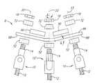
- FIG. 1Ais an exploded side view of a spinal fixation system, in accordance with the present invention.
- FIG. 1Bis a side view of the system of FIG. 1A implanted to stabilize a plurality of vertebrae.
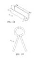
- FIG. 2Ais a perspective view of a spacer clip, in accordance with the present invention.
- FIG. 2Bis a side view of a crimping tool for use with the spacer clip of FIG. 2 A.
- FIG. 3Ais a perspective view of a preferred embodiment of an anchor screw assembly, in accordance with the present invention.
- FIG. 3Bis an exploded perspective view of the anchor screw assembly of FIG. 3 A.
- FIGS. 4A and 4Bare perspective and side views, respectively, of a screw for the anchor screw assembly of FIGS. 3A and 3B.
- FIGS. 5A-5Care perspective and first and second side views, respectively, of a swing bolt for the anchor screw assembly of FIGS. 3A and 3B.
- FIGS. 6A-6Care perspective and first and second side views, respectively, of an assembled screw and swing bolt for the anchor screw assembly of FIGS. 3A and 3B.
- FIGS. 7A-7Care perspective and first and second side views, respectively, of a first embodiment of a lower clamp portion for a clamp assembly, in accordance with the present invention.
- FIGS. 8A-8Care perspective and first and second side views, respectively, of a first embodiment of an upper clamp portion for a clamp assembly, in accordance with the present invention.
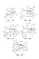
- FIGS. 9A-9Eare perspective views of alternative embodiments of a lower clamp portion, in accordance with the present invention.
- FIGS. 10A-10Eare perspective views of alternative embodiments of an upper clamp portion, in accordance with the present invention.
- FIGS. 11A and 11Bare perspective and side views, respectively, of another embodiment of an anchor screw, in accordance with the present invention.
- FIGS. 12A-12Cshow a spinal fixation system being implanted between vertebrae of a patient, in accordance with the present invention.
- FIG. 13shows a pair of spinal fixation systems implanted along a patient's spine, in accordance with the present invention.
- FIG. 14is a perspective view of another preferred embodiment of an anchor screw assembly, in accordance with the present invention.
- FIGS. 15A and 15Bare top and front views, respectively, of an upper clamp portion for use with the anchor screw assembly of FIG. 14 .
- FIG. 15Cis a front view of an alternative embodiment of an upper clamp portion for use with the anchor screw assembly of FIG. 14 .
- FIGS. 1A and 1Bshow a preferred embodiment of a spinal fixation system 8 , in accordance with the present invention.
- the system 8includes a plurality of anchor screw assemblies, 10 , a rod 86 securable between the anchor screw assemblies 10 , and one or more spacer clips 90 securable to the rod 86 .
- All of the components of the system 8may be made from a variety of biocompatible materials, e.g., metals, and preferably from titanium or alloys including titanium.
- the rod 86may be a substantially rigid elongate member, e.g., a solid rod, having a generally round cross-section.
- the rod 86has one or more flattened regions (not shown) extending between ends 88 of the rod 86 .
- the rod 86may include opposing flattened regions (not shown), thereby defining a flattened elliptical cross-section.
- the rod 86may include serrations or teeth (not shown) extending between the ends 88 , which may facilitate securing the rod 86 to the anchor screw assemblies 10 .
- the rod 86may be substantially straight initially (not shown), and may be bent and/or curved during a procedure, e.g., to conform to the natural curvature or lordosis of the anatomy encountered, as shown in FIG. 1A, and as described further below.
- the rod 86is sufficiently rigid, however, such that, once bent, the rod 86 may substantially retain its bent shape when subjected to forces experienced during normal activity of a patient, as will be appreciated by those skilled in the art.
- a spacer clip 90is shown that may be secured to the rod 86 .
- the clip 90is a “C” shaped member including opposing edges 91 defining a pocket 92 that extends between ends 94 of the clip 90 .
- the pocket 92has a cross-section that is larger than the rod 86 such that the clip 90 may be received at least partially around the rod 86 .
- the clip 90may be malleable such that a tool, such as the crimping tool 95 shown in FIG. 2B, may be used to crimp or otherwise compress at least portions of the opposing edges 91 around the rod 86 after the clip 90 has been placed on the rod 86 to secure the clip 90 to the rod 86 .
- a variety of clipsmay be provided, e.g., having standard lengths “L” and/or cross-sections.
- a set of clips(not shown) may be provided that have lengths from about one to about three centimeters (1-3 cm), e.g., at 0.125 centimeter intervals.
- the ends 94 of the clip 90are preferably substantially square, although alternatively, they may be tapered, e.g., such that the length of the clip as measured along the edges 91 is greater than the length as measured from the bottom of the pocket 92 (not shown).
- each of the anchor screw assemblies 10includes a screw 12 , a swing bolt 14 pivotally coupled to the screw 12 to provide an anchor screw 15 , and a clamp assembly 16 securably received on the swing bolt 14 , as shown in FIGS. 3A and 3B.
- other anchor screw assembliesmay be used to provide a system in accordance with the present invention.
- a rigid anchor screw 90such as that shown in FIGS. 11A and 11B, may be used instead of an anchor screw 15 including a swing bolt 14 .
- other anchor screw assembliesmay be used, e.g., including saddle or clamp assemblies mounted on screw bolts, such as those disclosed in U.S. Pat. Nos. 4,653,481, 5,487,744, and 5,545,166, the disclosures of which are expressly incorporated herein by reference.
- any known anchor screw assembliesmay be used, although the anchor screw assemblies shown and described herein may be particularly advantageous.
- the screw 12 of the anchor screw 15generally includes a first threaded portion 20 terminating in a tip 22 , and a second head portion 24 opposite the tip 22 .
- the threaded portion 20may include a helical thread 21 defining a thread pattern, preferably configured for substantially securing the screw 12 into bone, such as a portion of a vertebra (not shown).
- the thread spacingmay be between about three to six threads per centimeter (3-6 threads/cm), and preferably about 4.8 threads per centimeter (about 12 threads per inch).
- the thread spacingmay be substantially constant between the tip 22 and the head portion 24 or may vary along the length of the threaded portion 20 .
- the leading and trailing edges of axially adjacent portions of the thread 21may define an inclusive angle “ ⁇ ” between them of between about twenty to forty degrees (20-40°), and preferably about thirty degrees (30°).
- each thread 21is rounded or tapers outwardly from the root diameter to the major diameter of the thread 21 , such that the leading and trailing edges on either side of a portion of the thread 21 define tangent lines that intersect one another adjacent the outer edge of the respective portion of the thread 21 .
- the thread 21may have a height of between about 0.50-3.00 millimeters, and preferably between about 0.60-2.00 millimeters.
- the threaded portion 20may have desired dimensions to accommodate threading into bone, such as a vertebra (not shown).
- the threaded portion 20may have an outer diameter between about 3.5-8.5 millimeters, preferably between about 5.8-8.5 millimeters, and a length between about 25-65 millimeters, and preferably between about 35-65 millimeters.
- the threaded portion 20may have a substantially uniform major and minor diameter along its length.
- the threaded portion 20may have a taper, e.g., reducing in minor and/or major diameter from the head portion 24 towards the tip 22 .
- the thread 21may have a substantially uniform height, or may become increasingly higher from the head portion 24 towards the tip 22 , e.g., if the threaded portion 20 is tapered, to provide a substantially uniform outer diameter for the threaded portion 20 .
- the threaded portion 20may include a pull-out portion 21 A, which may facilitate manufacturing of the anchor screw 12 and/or may improve engagement of the screw 12 with bone into which the screw 12 is threaded.
- a pull-out portion 21 Amay facilitate manufacturing of the anchor screw 12 and/or may improve engagement of the screw 12 with bone into which the screw 12 is threaded.
- Other thread patterns and screw designsmay also be used for an anchor screw assembly in accordance with the present invention, as found in U.S. Pat. Nos. 4,854,311, 5,034,011, and 5,226,766, the disclosures of which are expressly incorporated herein by reference.
- the head portion 24generally has a cross-section larger than the threaded portion 20 and includes a full-radius shoulder 28 opposite the threaded portion 20 .
- the shoulder 28includes a predetermined radius about a pivot axis 35 to facilitate pivoting of the swing bolt 14 and/or the clamp assembly 16 (shown in FIGS. 3A and 3B) with respect to the head portion 24 , as explained further below.
- the head portion 24includes a slot 30 therein extending generally parallel to a longitudinal axis 32 of the screw 12 , thereby dividing the head portion 24 into ears 26 .
- Pin holes 34extend through the ears 26 along the pivot axis 35 , i.e., substantially perpendicular to the longitudinal axis 32 .
- the swing bolt 14includes an elongate body 34 including a first looped region 36 , a second noncircular intermediate region 38 , and a third threaded region 40 generally opposite the looped region 36 .
- the looped region 36may be substantially narrower than the other regions of the swing bolt 14 , i.e., having a width slightly smaller than a width of the slot 30 in the screw 12 such that the looped region 36 may be received in the slot 30 between the ears 26 , as shown in FIGS. 6A-6C.
- the looped region 36has a pin hole 37 therethrough that extends substantially perpendicular to the longitudinal axis 32 .
- the noncircular region 38 of the swing bolt 14is preferably substantially smooth-walled and has a noncircular cross-section, preferably for slidably receiving the clamp assembly 16 thereon (as shown in FIGS. 3 A and 3 B), while preventing rotation of the clamp assembly 16 about longitudinal axis 33 .
- one or more flat walls 42are formed along the intermediate region 38 .
- the cross-sectionmay define a flattened elliptical shape, a “D” shape.
- other shapesmay be used, such as a hexagon, a square, a star, or other noncircular geometric shape.
- the looped region 36 of the swing bolt 14may be received in the slot 30 of the head portion 24 , and a pin 44 may be received through the pin holes 34 , 37 to provide anchor screw 15 .
- the pin 44may fix the swing bolt 14 to the screw 12 , while allowing the swing bolt 14 and screw 12 to pivot with respect to one another such that the longitudinal axes 32 , 33 intersect, but define an angle “theta” greater than zero degrees, as shown in phantom in FIG. 6 B.
- the clamp assembly 16(shown in FIGS. 3A and 3B) generally includes a first lower clamp portion 52 and a second upper clamp portion 72 .
- the lower and upper clamp portions 52 , 72have noncircular bolt passages 54 , 74 that extend entirely through them between lower surfaces 56 , 76 and upper surfaces 58 , 78 , respectively, thereby defining a first axis 60 .
- the bolt passages 54 , 74preferably have a cross-section similar to the cross-section of the noncircular region 42 of the swing bolt 14 (see FIGS. 3B, 5 A, 5 B, 6 A, and 6 B).
- the bolt passages 54 , 74may accommodate receiving the swing bolt 14 therethrough, while preventing rotation of the clamp assembly 16 on the swing bolt 14 , as explained further below.
- the lower and upper clamp portions 52 , 72have generally semi-cylindrical grooves 62 , 82 therein that cooperate with one another when the clamp assembly 16 is assembled to define a rod passage 64 , as shown in FIG. 3 A.
- the rod passage 64generally extends along a second axis 66 that is transverse to, and preferably substantially perpendicular to, the first axis 60 .
- the second axis 66is also substantially perpendicular to a third axis 70 that extends along a length of the lower clamp portion 52 substantially perpendicular to both the first and second axes 60 , 66 (thus, the three axes 60 , 66 , 70 may be orthogonal to one another).
- the rod passage 64has a cross-section similar to a rod 86 (not shown, see FIG. 1A) that may be received therein.
- the cross-sectionmay be generally circular, but optionally may be noncircular, e.g., circular with one or more flattened walls, such as wall 83 shown in the upper clamp portion 72 in FIGS. 8B and 8C.
- the rod passage 64may have other geometric shapes, similar to the bolt passages 54 , 74 , described above.
- one or both of the grooves 62 , 82may include teeth or other serrations (not shown) for enhancing engagement with the rod received in the rod passage 64 (shown in FIG. 3 A), either alone or in combination with one of the cross-sections described above. Exemplary serrations are shown in U.S. Pat. Nos. 4,653,481 and 5,545,164, the disclosures of which are expressly incorporated herein by reference.
- the groove 82 in the upper clamp portion 72extends along the lower surface 76 .
- the upper surface 78may be recessed around the bolt passage 74 , thereby accommodating a fastener (not shown) thereon, while minimizing the profile of the resulting clamp assembly.
- the groove 82may define a hump 79 opposite the lower surface 76 , which may be higher than the upper surface 78 .
- the hump 79may have a height similar to a nut or other fastener (not shown) that may be attached to a swing bolt (also not shown) that is inserted through the bolt passage 74 .
- the upper surface of the fastener 18may define a height similar to the hump 79 (also as shown in FIG. 3 A), thereby substantially minimizing a profile of the anchor screw assembly and/or reducing tissue irritation.
- side edges 84 of the upper clamp portionmay be substantially square with the lower surface 76 , i.e., the side edges 84 may extend substantially parallel to the first axis 60 .
- the side edges 84 ′may be tapered.
- the side edges 84 ′ of the upper clamp portion 72 ′may taper inwardly towards the hump 79 ′ such that they define an angle ⁇ between about one and twenty degrees (1-20°) with the first axis 60 ′, and preferably about ten degrees (10°).
- Such a tapermay be machined into the side edges 84 ′ or formed using other known methods.
- the side edges 84may be substantially square, and a spot face, recess, or notch 85 ′′ may be formed around the groove 82 ,′′ e.g., by spot facing the side edges 84 .′′
- These tapered or recessed featuresmay enhance abutment with ends 94 of the spacer clip 90 despite the natural curvature or lordosis of a spinal column (not shown) when the spacer clip 90 is secured to a curved rod 86 (not shown, see FIGS. 1 A and 1 B), as explained further below.
- the groove 62 in the lower clamp portion 52extends along the upper surface 58 .
- the lower clamp portion 62also includes a recess 68 in the lower surface 56 that intersects the bolt passage 54 .
- the recess 68preferably has a radius of curvature similar to the shoulder 28 on the head portion 24 of the screw 12 (see FIGS. 6 A- 6 C), as explained further below.
- the lower surface 76 of the upper clamp portion 72 and the upper surface 58 of the lower clamp portion 52are substantially flat such that the lower and upper clamp portions 52 , 72 may substantially abut one another to provide the rod passage 64 .
- the upper and lower surfaces 58 , 76may include mating segments, e.g., cooperating tabs and slots or other male/female connectors (not shown), that may positively engage one another when the lower and upper clamp portions 52 , 72 are disposed in the proper orientation.
- the clamp assembly 16may be received on the swing bolt 14 , e.g., by orienting the clamp assembly 16 such that the bolt passages 54 , 74 are properly aligned with the noncircular region of the swing bolt 14 .
- the lower clamp portion 52may be directed over the swing bolt 14 and then the upper clamp portion 72 may be received over the swing bolt 14 , i.e., through the bolt passages 54 , 74 , respectively.
- a fastener, e.g., nut 18may be threaded onto the threaded region 40 of the swing bolt 14 until it engages upper surface 78 of the upper clamp portion 72 , thereby forcing the clamp assembly 16 towards the head portion 24 of the screw 12 . Consequently, the lower clamp portion 52 may abut the head portion 24 such that the shoulder 28 is received in the recess 68 in the lower surface 56 .
- the lower clamp portion 52may slide along the shoulder 28 as the swing bolt 14 is pivoted with respect to the screw 12 .
- the nut 18may be further tightened until the wall of the recess 68 frictionally engages the shoulder 28 , thereby substantially securing the swing bolt 14 at the desired angle relative to the screw 12 .
- FIGS. 9A-10Eseveral alternative embodiments of lower and upper clamp portions are shown that together may provide clamp assemblies that may be received over the screw assembly 15 of FIGS. 6A-6C.
- the lower and upper clamp portions 152 , 172 shown in FIGS. 9A and 10Aare generally similar to that shown in FIGS. 7A and 8A, except that the flat regions 155 , 175 of the bolt passages 154 , 174 and the recess 168 are offset ninety degrees from the previous embodiment.
- the resulting clamp assembly(not shown) may be mounted similar to the previous embodiment, but offset ninety degrees with respect to the anchor screw (not shown).
- FIGS. 9B and 10Banother set of lower and upper clamp portions 252 , 272 are shown that are similar to the embodiments of FIGS. 9A and 10A, except that the grooves 262 , 282 are located further away from the bolt passages 254 , 274 along the third axis 270 .
- the resulting clamp assembly from these embodimentsmay be mounted on the anchor screw similar to the previous embodiment with the shoulder 28 of the screw 12 being received in the recess 268 .
- a rod (not shown) received in the resulting rod passagewill be disposed further from the anchor screw than the previous embodiment.
- FIGS. 9C and 10Cyet another set of lower and upper clamp portions 352 , 372 are shown that are similar to the embodiments of FIGS. 9A and 10A, except that the bolt passages 354 , 374 have an elongated elliptical shape extending along the third axis 370 .
- the lower surface 356 of the lower clamp portion 352includes adjacent recesses 368 , 369 that intersect the bolt passage 354 and may overlap one another.
- the resulting clamp assembly from this embodimentmay be secured to the anchor screw such that either of the recesses 368 , 369 slidably engages the shoulder of the screw (not shown), thereby allowing a rod (also not shown) received in the rod passage to be disposed at two possible locations, e.g., distances, relative to the anchor screw.
- a rodalso not shown
- more than two recessesmay be provided, thereby allowing the rod passage to be disposed at multiple distances from the anchor screw.
- FIGS. 9D and 10Dstill another set of lower and upper clamp portions 452 , 472 are shown that are similar to the embodiments of FIGS. 7A and 8A, except that the grooves 462 , 482 and recess 468 are aligned such that the second axis 466 defines an angle “ ⁇ ” with the third axis 470 .
- the angle “ ⁇ ”is between about ten and seventy degrees (10-75°), and more preferably between about thirty and forty five degrees (30-45°).
- the flattened wall regions 455 , 475are aligned substantially parallel to the second axis 466 , thereby also defining an angle “ ⁇ ” with respect to the third axis 470 .
- FIGS. 9E and 10Eanother set of lower and upper clamp portions 552 , 572 are shown that are similar to the embodiments of FIGS. 9D and 10D, except that the bolt passages 554 , 574 , recess 568 , and grooves 562 , 582 are mirror opposites or opposite-hand of those in the previous embodiment.
- a variety of clamp assembliesmay be providing including a range of dimensions, e.g., lengths, thicknesses, “ ⁇ ” angles, and the like, in any combination or subcombination of the features described above.
- FIGS. 11A and 11Banother preferred embodiment of an anchor screw 90 is shown that includes a threaded portion 92 terminating in a tip 93 , and an enlarged head portion 94 including a noncircular region 96 and a threaded region 98 opposite the tip 93 .
- the threaded portion 92may include any of the features and/or dimensions described above for the anchor screw 12 of FIGS. 4A-4C, e.g., thread pattern, outer diameter, taper, and the like.
- the threaded region 98may receive a fastener, such as the nut described above (not shown), e.g., to substantially secure a clamp assembly (also not shown) on the noncircular region 96 , similar to the embodiment described above.
- the anchor screw 90may receive any of the clamp assemblies described above.
- a kitmay be provided (not shown).
- the kitmay include a plurality of anchor screws, clamp assemblies, and fasteners that may be selected based upon the specific vertebrae being treated and/or based upon the anatomy encountered.
- Each anchor screw assemblymay include an anchor screw, e.g., a pivoting or fixed anchor screw, and one or more clamp assemblies.
- a plurality of upper and lower clamp assembliesmay be provided, having different dimensions, as described above.
- An appropriate paircorresponding to the patient anatomy encountered, may be selected for each anchor screw.
- One or more rodsmay be provided, and an apparatus (not shown) may be provided for bending the rod(s) in a desired configuration during a procedure.
- a plurality of spacer clipsmay be provided, e.g., having different lengths, as described above, and a tool, e.g., a crimper or plyers, may be provided for crimping the spacer clip.
- a toole.g., a crimper or plyers
- an exemplary system 1000is shown that includes a pair of rods 1002 that are each implanted along a spinal column using three swing bolt anchor screws 1010 - 1014 and three clamp assemblies, 1016 - 1020 .
- one or more of the swing bolt anchor screwssuch as the outside anchor screws 1010 , 1014 , may be replaced with nonpivoting anchor screws (such as that shown in FIGS. 11 A and 11 B).
- fewer or additional anchor screwsmay be implanted, e.g., to secure a shorter or longer rod and/or to fix fewer or additional vertebrae.
- the rods 1002are implanted generally parallel to the central spinal axis on either side of the spinous processes 902 , as shown in FIG. 13 .
- the system 1000may be used to provide adjustment of the vertebrae, e.g., to allow vertical or horizontal, medial or lateral adjustment.
- an implantation procedure for only one rod 1002is described below, it will be appreciated that a second rod (or even additional rods) may be implanted using a similar procedure.
- the vertebraee.g., vertebrae 910 , 920 , 930
- the anchor screws 1010 - 1014are screwed into the vertebrae 910 - 930 , respectively, e.g., into the pedicles.
- the anchor screws 1010 - 1014are screwed in sufficiently to provide a predetermined pivot axis with respect to a centerline spinal axis of the patient.
- the anchor screw 1012may be screwed into the pedicle until a pivot axis 1032 of the anchor screw 1012 is disposed generally parallel to the centerline spinal axis 908 .
- the other anchor screws 1010 , 1014may be screwed into their respective vertebrae until their respective pivot axes 1030 , 1034 are disposed substantially transverse to the first pivot axis 1032 , and preferably substantially perpendicular to the centerline spinal axis.
- Clamp assemblies 1016 - 1020are selected based upon the anatomy encountered.
- the clamp assembly 1016may be similar to the clamp assembly 52 , 72 shown in FIGS. 7A and 8A
- the clamp assembly 1018may be similar to the clamp assembly 152 , 172 of FIGS. 9A and 10A, i.e., having a longer length than the clamp assembly 1016
- the clamp assembly 1020may be similar to the clamp assembly 452 , 472 shown in FIGS. 9B and 10B, i.e., having a groove 1028 a (see FIG. 12A) that extends in line with the grooves 1024 a , 1026 a of the clamp assemblies 1016 , 1018 .
- the lower clamp portions 1016 a - 1020 a of the clamp assemblies 1016 - 1020may be received over the noncircular regions (not shown) of the anchor screws 1010 - 1014 , as best seen in FIG. 12 A.
- a rod 1002may be received in the grooves 1024 a - 1028 a in the lower clamp portions 1016 a - 1020 a , thereby extending between the anchor screws 1010 - 1014 , as shown in FIG. 12 B.
- the rod 1002may be bent to a predetermined shape, as needed, to conform to the anatomy alignment encountered.
- the rod 1002is bent in only one plane, e.g., the sagetal plane, while remaining substantially straight in the coronal plane, as shown in FIG. 1 A.
- “Sagetal” planerefers to the plane that may be seen from a lateral view of the patient, e.g., that is viewed horizontally when the patient is lying face-down (such as the plane seen in FIGS. 1 A and 1 B). “Coronal” plane refers to the plane that may be seen from an anterior or posterior view of the patient, e.g., that is viewed vertically up the length of the spine when the patient is lying face-down (such as that shown in FIGS. 12 A- 12 C).
- the flattened region(s) 1004may be oriented so that they may engage similar flattened regions (not shown) in the rod passages 1024 - 1028 in the clamp assemblies 1016 - 1020 (e.g., in the upper clamp portions 1016 b - 1020 b ).
- One or more of the clamp assemblies 1016 - 1020may be adjusted at any time during the procedure.
- the swing bolts on the anchor screws 1010 - 1014may be pivoted about their respective pivot axes 1030 - 1034 with respect to the threaded portions that have been threaded into the vertebrae 910 - 930 .
- the lower clamp portions 1016 a - 1020 amay be adjusted before and/or after the rod 1002 is received in the grooves 1024 a - 1028 a .
- a uniaxial devicei.e., pivoting in a single axis
- Thismay minimize the amount of bending required of the rod 1002 , preferably requiring bending in only one plane (preferably, the sagetal plane), thereby substantially maximizing the rigidity of the rod 1002 .
- upper clamp portions 1016 b - 1020 bmay be placed on the lower clamp portions 1016 a - 1020 a , i.e., received on the swing bolts of the anchor screws 1010 - 1014 .
- the grooves (not shown) in the upper clamp portions 1016 b - 1020 bsubstantially engage the rod 1002 .
- Fasteners, such as nuts 1022may then by threaded onto the swing bolts, thereby substantially securing the rod 1002 between the upper and lower clamp portions 1016 - 1020 .
- the nuts 1022are twelve point jam nuts.
- the nuts 1022may have rounded upper edges, which may minimize tissue irritation, e.g., of tissue overlying the nuts 1022 after implantation of the system 1000 .
- the nuts 1022may include a crimpable rim (not shown), which may be crimped when the nuts are tightened to a desired torque, e.g., to prevent subsequent loosening of the nuts.
- a crimpable rimnot shown
- hex nuts or other fastenersmay be used.
- the lower clamp portions 1016 a - 1020 ainclude radiused recesses (not shown) on their lower surfaces that intersect bolt passages for receiving the swing bolts 1010 - 1014 therein. These recesses may slidably engage similarly radiused shoulders on screws of the swing bolts (not shown), as described above. Thus, as the angles of the swing bolts are adjusted, the shoulders may pivotally slide along the surfaces of the recesses of the lower clamp portions 1016 a - 1020 a .
- the nuts 1022may be tightened, thereby causing the lower clamp portions 1016 a - 1020 a to frictionally engage the shoulders and secure the swing bolts with respect to the threaded portions without substantially moving one or more of the vertebrae out of the desired position.
- each individual clamp assemblyis uniaxial, i.e., may only be pivoted about a single axis. By setting the axes of the anchor screws substantially transverse relative to one another, substantially flexibility may be obtained without substantially compromising vertebra position. Because of the uniaxial nature of the clamp assemblies, the system may be less likely to become misaligned when the patient resumes normal activity than a polyaxial system.
- spacer clips 90may be placed on the rod 1004 between adjacent anchor screw assemblies.
- FIGS. 1A and 1Ban exemplary system 8 is shown that has been implanted into vertebrae 910 , 920 , 930 .
- spacer clips 90may be placed around and crimped to exposed portions of rod 86 that extends between adjacent clamp assemblies 10 , 10 ′.
- two anchor screw assemblies 10including upper clamp portions 16 with square side edges 84 (such as that shown in FIG. 3A) and one anchor screw assembly 10 ′ (such as that shown in FIG. 14) with an upper clamp portion 16 ′ with tapered side edges 84 ′ have been selected. Because of the natural curvature or lordosis defined by the vertebrae 910 , 920 , 930 , the longitudinal axes 33 of adjacent anchor screws 15 may define an angle ⁇ relative to one another. To match this natural curvature, the rod 86 may be bent to also define an angle ⁇ .
- the upper clamp portion 16 ′may be tapered, as described above with reference to FIGS. 15A and 15B, also to define an angle ⁇ relative to the longitudinal axis 33 .
- the opposing side edges 84 , 84 ′ of the adjacent upper clamp portions 72 , 72 ′may be oriented substantially parallel to one another, as best seen in FIG. 1 B.
- the distance “L” between the opposing side edges 84 , 84 ′may be measured, and an appropriate spacer clip 90 , e.g., having a length approximately “L” (or less than “L”), i.e., corresponding substantially to the measured distance, may be placed on the exposed portion of the rod 86 between the adjacent clamp assemblies 16 , 16 ′.
- the spacer clip 90may be crimped around the rod 86 , e.g., by compressing the opposing edges 91 (not shown, see FIG. 2A) of the clip 90 using a crimper tool 95 (not shown, see FIG. 2B) to malleably deform the opposing edges 91 towards one another.
- the crimper tool 95may be sufficiently long that a substantial length of the clip 90 may be engaged therein.
- one or more successive portions along the length of the clip 90may be crimped around the rod 86 with the tool 95 . This placement and crimping process may be repeated for each exposed portion of the rod(s) 90 extending between adjacent clamp assemblies 16 , 16 ′.
- the spacer clips 90provide axial support, e.g., once the patient returns to a vertical position, thereby preventing the adjacent clamp assemblies 16 , 16 ′ from moving substantially towards one another.
- the spacer clips 90may enhance the system 8 remaining in the final configuration set during the procedure and minimize any slippage of the system 8 once the patient resumes normal activity.
- the ends of the clip(s)may be received in the recesses, thereby preventing the clip(s) from being dislocated from the rod once the patient assumes normal activity.
- the patientmay be placed under traction or the vertebrae may otherwise be distracted away from one another. This may provide sufficient space between the adjacent clamp assemblies to allow the spacer clip(s) to be placed around and/or otherwise secured to the rod(s).
- the vertebraeWhen distraction is removed, the vertebrae may return to a desired state, whereupon the spacer clip(s) substantially abut the adjacent clamp assemblies, thereby preventing axial movement of the clamp assemblies towards one another.
- the ends of the clip(s)may be received in the recesses in the sides of the clamp assemblies, thereby further securing the clip(s) relative to the rod.
- the spacer clipsthemselves may be tapered (not shown) to extend between and abut adjacent clamp assemblies.
Landscapes
- Health & Medical Sciences (AREA)
- Orthopedic Medicine & Surgery (AREA)
- Life Sciences & Earth Sciences (AREA)
- Neurology (AREA)
- Surgery (AREA)
- Heart & Thoracic Surgery (AREA)
- Engineering & Computer Science (AREA)
- Biomedical Technology (AREA)
- Nuclear Medicine, Radiotherapy & Molecular Imaging (AREA)
- Medical Informatics (AREA)
- Molecular Biology (AREA)
- Animal Behavior & Ethology (AREA)
- General Health & Medical Sciences (AREA)
- Public Health (AREA)
- Veterinary Medicine (AREA)
- Surgical Instruments (AREA)
Abstract
Description
This application is a continuation-in-part of application Ser. No. 09/861,278, filed May 17, 2001, the disclosure of which is expressly incorporated herein by reference.
The present invention relates generally to apparatus and methods for treating spinal disorders, and more particularly to spinal fixation systems that may be secured between adjacent anchor screw assemblies, and methods for stabilizing, adjusting, or otherwise fixing adjacent vertebrae using such spinal fixation systems.
Various systems and methods have been suggested for treating spinal disorders, such as degenerative discs, stenosis, trauma, scoliosis, kyphosis, or spondylolisthesis. For example, U.S. Pat. No. 5,545,166, naming the same inventor as the present application, discloses a spinal fixation system that includes a plurality of anchor screws, clamp assemblies, pivot blocks, clamp blocks, and rods that are implanted along a patient's spine to fix two or more adjacent vertebrae relative to one another. The system generally includes a swing bolt anchor screw, a pivot block receivable on the swing bolt, and a clamp block receiving a rod therethrough that is pivotally attachable to the pivot block. In addition, the system includes one or more fixed anchor screws, and clamp assemblies for receiving the rod therein. The clamp assemblies and pivot block are receivable on the anchor screws by spindles that thread along a threaded portion of the anchor screws.
During use, vertebrae to be treated are surgically exposed, and an arrangement of anchor screws and clamp accessories are selected. For example, a fixed anchor screw may be screwed into each of the vertebrae on either side of a first vertebra. A rod is selected that may extend between the fixed anchor screws and that may be bent to conform to the shape of the anatomy encountered. The rod is inserted through a loose clamp block, and the rod is placed in clamp assemblies that are received over the fixed anchor screws.
A swing bolt anchor screw is then screwed into the first vertebra adjacent the rod, and a pivot block is received on the swing bolt screw. The clamp block and/or pivot block are adjusted such that the clamp block may be engaged with a pivot on the pivot block. A set screw may then be screwed into the clamp block to secure the clamp block to the pivot. A pair of set screws are also screwed into the clamp block to secure the rod within the clamp block. Preferably, a pair of such systems are implanted on either side of the vertebrae.
During the procedure, it may be desirable to adjust the vertebrae relative to one another. Once the system(s) is(are) connected as described above, the set screws may be loosened and the rod(s), clamp block(s), and/or pivot block(s) may be adjusted, e.g., by moving the spindle(s) to adjust the height of the pivot block(s) and/or clamp assemblies on the anchor screws, by pivoting the swing bolt anchor screw(s), and/or pivoting the clamp block(s) relative to the pivot block(s). Once the vertebrae have been moved into a desired position, the set screws may be tightened, and the spindles secured in position by crimping the walls surrounding the spindles.
An advantage of this system is that the swing bolt anchor screw, pivot block, and clamp block arrangement allows the system to be adjusted about two axes, i.e., the axis of the swing bolt anchor screw and the axis of the pivot on the pivot block. However, because the system of the '166 patent is polyaxial, i.e., may pivot about multiple axes, there is greater risk of the system coming out of alignment when the patient resumes normal physical activity.
This system is also very complicated, involving six parts, including three set screws, that are mounted on each swing bolt anchor screw. In addition, because the swing bolt is threaded, an intricate spindle device is required in order to allow the pivot block and clamp assemblies to be threaded onto the swing bolt, and still control their orientation about the axis of the swing bolt. Thus, because of its complexity and many intricate parts, this system may be expensive to manufacture and/or difficult to implant.
Accordingly, apparatus and methods for stabilizing, adjusting, and/or fixing vertebrae would be considered useful.
The present invention is directed to spinal fixation systems that may be secured between adjacent anchor screw assembles, e.g., to rods extending between the anchor screw assemblies, and to methods for stabilizing, adjusting, or otherwise fixing adjacent vertebrae using such spinal fixation systems.
In accordance with one aspect of the present invention, a spinal fixation system is provided that includes a first anchor screw assembly including a first passage and a first screw, the first screw having a threaded portion configured to be screwed into a first vertebra, and a second anchor screw assembly including a second passage and a second screw, the second screw having a threaded portion configured to be screwed into a second vertebra adjacent the first vertebra. In an exemplary embodiment, one or both of the anchor screw assemblies may include a saddle or clamp assembly receivable on the respective screw, each saddle assembly including a rod passage therethrough defining the first and second passages. Preferably, the saddle assemblies include upper and lower saddles or clamp portions that may together define the rod passage.
A rod or other elongate member is receivable in the first and second passages, the elongate member including an exposed portion extending between the first and second anchor screw assemblies. A spacer is securable on the exposed portion of the elongate member, the spacer having a length substantially similar to a length of the exposed portion of the elongate member for preventing the first and second anchor screw assemblies from moving towards one another.
In accordance with another aspect of the present invention, a kit is provided for stabilizing vertebrae relative to one another. Generally, the kit includes one or more substantially rigid rods, and a plurality of “C” shaped spacers having a plurality of lengths, the spacers including opposing edges defining a pocket therebetween for receiving the one or more rods therein. The kit may also include a plurality of anchor screw assemblies, the anchor screw assemblies including anchor screws and a plurality of clamp assemblies for receiving the one or more rods therein.
Optionally, the kit may also include a tool for crimping at least a portion of the opposing edges of the spacers around the one or more rods to secure the spacers to the rods. In another option, the kit may include an apparatus for bending the one or more rods, e.g., to conform substantially to a natural curvature of a patient's spinal column being treated.
In accordance with still another aspect of the present invention, a method is provided for stabilizing vertebrae relative to one another, the vertebrae being disposed adjacent one another along a central spinal axis. A first anchor screw may be screwed into a first vertebra, and a second anchor screw may be screwed into a second vertebra adjacent the first vertebra. A rod or other elongate member may be secured between the first and second anchor screws, e.g., using clamp assemblies, thereby fixing a relative distance of the first and second vertebrae.
A spacer, e.g., a “C” shaped clip, may be secured or otherwise placed on the elongate member, e.g., by crimping the spacer around the elongate member. Preferably, the spacer extends substantially an entire length of the elongate member that is exposed between the first and the second anchor screws to prevent the first and second anchor from moving towards one another. For example, the spacer may abut clamp assemblies on the first and second anchor screws, thereby preventing the clamp assemblies, and consequently the anchor screws, from moving substantially towards one another. One or both of the clamp assemblies may have a tapered side portion to enhance abutment of the spacer and the clamp assemblies if the elongate member is bent, e.g., to conform to the natural curvature of the anatomy encountered.
In accordance with yet another aspect of the present invention, an anchor screw assembly is provided that includes a screw having a first threaded portion, and a second head portion. A swing bolt is pivotally coupled to the second portion of the screw. The swing bolt defines a first axis, and includes a noncircular region extending along the first axis, the noncircular region having a noncircular cross-section and a substantially smooth wall. In addition, the swing bolt may include a threaded region on its end opposite the screw.
A clamp assembly may be provided that includes first and second clamp portions that are receivable on the swing bolt. Each clamp portion has a noncircular first passage therethrough for receiving the noncircular region of the swing bolt therethrough. Thus, the noncircular region and the first passage have like cross-sections, thereby preventing rotation of the clamp assembly with respect to the swing bolt about the first axis when the noncircular region of the swing bolt is received in the first passages.
In addition, the first and second clamp portions have cooperating grooves therein, the cooperating grooves together defining a second passage extending along a second axis substantially transversely to the first axis when the first and second clamp portions are received on the swing bolt.
A fastener, e.g., a nut, is also provided for securing the clamp assembly on the swing bolt, e.g., that may be threaded onto the threaded region of the swing bolt to secure the clamp assembly on the swing bolt. In a preferred embodiment, the second portion of the screw includes a shoulder, and the clamp assembly may substantially engage the shoulder when the clamp assembly is fully secured on the swing bolt, thereby preventing the swing bolt from pivoting with respect to the screw.
In accordance with still another aspect of the present invention, a spinal fixation system is provided that includes a first anchor screw assembly, such as that described above. The first anchor screw assembly includes a first screw having a threaded portion, and a swing bolt pivotally coupled to the screw and including a noncircular region. The spinal fixation system also includes a plurality of clamp assemblies, including a first passage for receiving the first swing bolt therethrough, and a second passage for receiving an elongate member, e.g., a substantially rigid rod, therethrough. The dimensions of each clamp assembly may be different, e.g., including a second passage that is at one of a plurality of distances from the first passage and/or that is oriented at a predetermined angle along the clamp assembly. A fastener may be used for securing a selected clamp assembly on the swing bolt. Thus, when the selected clamp assembly is received on the first swing bolt, the first clamp assembly is fixed in a predetermined orientation with respect to a first pivot axis of the first swing bolt.
The spinal fixation system also includes a second anchor screw assembly including a second screw having a threaded portion and a hub, and a second selected clamp assembly receivable on the hub. The second screw may be a fixed screw or, preferably, a swing bolt anchor screw, similar to that described above. The second clamp assembly includes a third passage therethrough along a third axis. The second screw assembly may be oriented, when implanted, such that the third axis is substantially transverse to the first axis. Optionally, additional anchor screw assemblies may also be provided.
In accordance with another aspect of the present invention, a method is provided for simple alignment or otherwise stabilizing vertebrae relative to one another using a plurality of swing bolt anchor screw assemblies, such as those described above. A threaded portion of a first swing bolt anchor screw is screwed into a first vertebra until a first pivot axis of the first swing bolt anchor screw is generally parallel to the spinal axis. A threaded portion of a second swing bolt anchor screw is screwed into a second vertebra adjacent the first vertebra until a second pivot axis of the second swing bolt anchor screw is substantially transverse to the first pivot axis. If desired, a third anchor screw (or more) may be screwed into other vertebra adjacent to the first vertebra.
An angle of one or more swing bolts on the first and second swing bolt anchor screws may be adjusted about the first and second pivot axes. Lower clamp portions may be placed on the swing bolts of the first and second swing bolt anchor screws, either before or after the angle adjustments described above. A rod may be placed on the lower clamp portions, e.g., when the grooves in the lower clamp portions have been properly aligned with one another. Thus, the rod may extend between the first and second anchor screws, and between any additional anchor screws added generally in a straight line. In addition, if desired, the rod may be bent, e.g., in a single plane, to a predetermined configuration based upon anatomy encountered before securing the rod on the swing bolts.
Upper clamp portions may be secured on the swing bolts of the first and second swing bolt anchor screws, thereby securing the rod between the upper and lower clamp portions. For example, a nut or other fastener may be threaded onto the swing bolt after the upper and lower clamp portions, thereby securing the rod between the upper and lower clamp portions and/or securing the clamp assemblies on the swing bolts. These fasteners may also be loosened to allow adjustment of the vertebrae relative to one another, and then the fasteners may again be tightened to fix the vertebrae in desired relative positions. Optionally, a spacer, such as that described above, may be secured between the clamp assemblies to prevent movement of the swing bolts towards one another.
Other objects and features of the present invention will become apparent from consideration of the following description taken in conjunction with the accompanying drawings.
FIG. 1A is an exploded side view of a spinal fixation system, in accordance with the present invention.
FIG. 1B is a side view of the system of FIG. 1A implanted to stabilize a plurality of vertebrae.
FIG. 2A is a perspective view of a spacer clip, in accordance with the present invention.
FIG. 2B is a side view of a crimping tool for use with the spacer clip of FIG.2A.
FIG. 3A is a perspective view of a preferred embodiment of an anchor screw assembly, in accordance with the present invention.
FIG. 3B is an exploded perspective view of the anchor screw assembly of FIG.3A.
FIGS. 4A and 4B are perspective and side views, respectively, of a screw for the anchor screw assembly of FIGS. 3A and 3B.
FIGS. 5A-5C are perspective and first and second side views, respectively, of a swing bolt for the anchor screw assembly of FIGS. 3A and 3B.
FIGS. 6A-6C are perspective and first and second side views, respectively, of an assembled screw and swing bolt for the anchor screw assembly of FIGS. 3A and 3B.
FIGS. 7A-7C are perspective and first and second side views, respectively, of a first embodiment of a lower clamp portion for a clamp assembly, in accordance with the present invention.
FIGS. 8A-8C are perspective and first and second side views, respectively, of a first embodiment of an upper clamp portion for a clamp assembly, in accordance with the present invention.
FIGS. 9A-9E are perspective views of alternative embodiments of a lower clamp portion, in accordance with the present invention.
FIGS. 10A-10E are perspective views of alternative embodiments of an upper clamp portion, in accordance with the present invention.
FIGS. 11A and 11B are perspective and side views, respectively, of another embodiment of an anchor screw, in accordance with the present invention.
FIGS. 12A-12C show a spinal fixation system being implanted between vertebrae of a patient, in accordance with the present invention.
FIG. 13 shows a pair of spinal fixation systems implanted along a patient's spine, in accordance with the present invention.
FIG. 14 is a perspective view of another preferred embodiment of an anchor screw assembly, in accordance with the present invention.
FIGS. 15A and 15B are top and front views, respectively, of an upper clamp portion for use with the anchor screw assembly of FIG.14.
FIG. 15C is a front view of an alternative embodiment of an upper clamp portion for use with the anchor screw assembly of FIG.14.
Turning now to the drawings, FIGS. 1A and 1B show a preferred embodiment of aspinal fixation system 8, in accordance with the present invention. Generally, thesystem 8 includes a plurality of anchor screw assemblies,10, arod 86 securable between theanchor screw assemblies 10, and one or more spacer clips90 securable to therod 86. All of the components of thesystem 8 may be made from a variety of biocompatible materials, e.g., metals, and preferably from titanium or alloys including titanium.
Therod 86 may be a substantially rigid elongate member, e.g., a solid rod, having a generally round cross-section. Optionally, therod 86 has one or more flattened regions (not shown) extending between ends88 of therod 86. For example, therod 86 may include opposing flattened regions (not shown), thereby defining a flattened elliptical cross-section. Optionally, therod 86 may include serrations or teeth (not shown) extending between theends 88, which may facilitate securing therod 86 to theanchor screw assemblies 10.
Therod 86 may be substantially straight initially (not shown), and may be bent and/or curved during a procedure, e.g., to conform to the natural curvature or lordosis of the anatomy encountered, as shown in FIG. 1A, and as described further below. Therod 86 is sufficiently rigid, however, such that, once bent, therod 86 may substantially retain its bent shape when subjected to forces experienced during normal activity of a patient, as will be appreciated by those skilled in the art.
Turning to FIG. 2A, aspacer clip 90 is shown that may be secured to therod 86. Generally, theclip 90 is a “C” shaped member including opposingedges 91 defining apocket 92 that extends between ends94 of theclip 90. Thepocket 92 has a cross-section that is larger than therod 86 such that theclip 90 may be received at least partially around therod 86. Theclip 90 may be malleable such that a tool, such as the crimpingtool 95 shown in FIG. 2B, may be used to crimp or otherwise compress at least portions of the opposingedges 91 around therod 86 after theclip 90 has been placed on therod 86 to secure theclip 90 to therod 86.
A variety of clips may be provided, e.g., having standard lengths “L” and/or cross-sections. For example, a set of clips (not shown) may be provided that have lengths from about one to about three centimeters (1-3 cm), e.g., at 0.125 centimeter intervals. The ends94 of theclip 90 are preferably substantially square, although alternatively, they may be tapered, e.g., such that the length of the clip as measured along theedges 91 is greater than the length as measured from the bottom of the pocket92 (not shown).
Turning to FIGS. 3-8, each of theanchor screw assemblies 10 includes ascrew 12, aswing bolt 14 pivotally coupled to thescrew 12 to provide ananchor screw 15, and aclamp assembly 16 securably received on theswing bolt 14, as shown in FIGS. 3A and 3B. Alternatively, other anchor screw assemblies may be used to provide a system in accordance with the present invention. For example, arigid anchor screw 90, such as that shown in FIGS. 11A and 11B, may be used instead of ananchor screw 15 including aswing bolt 14. In a further alternative, other anchor screw assemblies may be used, e.g., including saddle or clamp assemblies mounted on screw bolts, such as those disclosed in U.S. Pat. Nos. 4,653,481, 5,487,744, and 5,545,166, the disclosures of which are expressly incorporated herein by reference. Thus, any known anchor screw assemblies may be used, although the anchor screw assemblies shown and described herein may be particularly advantageous.
Turning to FIGS. 4A and 4B, thescrew 12 of theanchor screw 15 generally includes a first threadedportion 20 terminating in atip 22, and asecond head portion 24 opposite thetip 22. The threadedportion 20 may include ahelical thread 21 defining a thread pattern, preferably configured for substantially securing thescrew 12 into bone, such as a portion of a vertebra (not shown). The thread spacing may be between about three to six threads per centimeter (3-6 threads/cm), and preferably about 4.8 threads per centimeter (about 12 threads per inch). The thread spacing may be substantially constant between thetip 22 and thehead portion 24 or may vary along the length of the threadedportion 20.
The leading and trailing edges of axially adjacent portions of thethread 21 may define an inclusive angle “α” between them of between about twenty to forty degrees (20-40°), and preferably about thirty degrees (30°). Preferably, eachthread 21 is rounded or tapers outwardly from the root diameter to the major diameter of thethread 21, such that the leading and trailing edges on either side of a portion of thethread 21 define tangent lines that intersect one another adjacent the outer edge of the respective portion of thethread 21. Thethread 21 may have a height of between about 0.50-3.00 millimeters, and preferably between about 0.60-2.00 millimeters.
The threadedportion 20 may have desired dimensions to accommodate threading into bone, such as a vertebra (not shown). For example, the threadedportion 20 may have an outer diameter between about 3.5-8.5 millimeters, preferably between about 5.8-8.5 millimeters, and a length between about 25-65 millimeters, and preferably between about 35-65 millimeters. The threadedportion 20 may have a substantially uniform major and minor diameter along its length. Alternatively, the threadedportion 20 may have a taper, e.g., reducing in minor and/or major diameter from thehead portion 24 towards thetip 22. Thethread 21 may have a substantially uniform height, or may become increasingly higher from thehead portion 24 towards thetip 22, e.g., if the threadedportion 20 is tapered, to provide a substantially uniform outer diameter for the threadedportion 20.
In addition, the threadedportion 20 may include a pull-outportion 21A, which may facilitate manufacturing of theanchor screw 12 and/or may improve engagement of thescrew 12 with bone into which thescrew 12 is threaded. Other thread patterns and screw designs may also be used for an anchor screw assembly in accordance with the present invention, as found in U.S. Pat. Nos. 4,854,311, 5,034,011, and 5,226,766, the disclosures of which are expressly incorporated herein by reference.
Thehead portion 24 generally has a cross-section larger than the threadedportion 20 and includes a full-radius shoulder 28 opposite the threadedportion 20. Theshoulder 28 includes a predetermined radius about apivot axis 35 to facilitate pivoting of theswing bolt 14 and/or the clamp assembly16 (shown in FIGS. 3A and 3B) with respect to thehead portion 24, as explained further below. Thehead portion 24 includes aslot 30 therein extending generally parallel to alongitudinal axis 32 of thescrew 12, thereby dividing thehead portion 24 intoears 26. Pin holes34 extend through theears 26 along thepivot axis 35, i.e., substantially perpendicular to thelongitudinal axis 32.
Turning to FIGS. 5A-5C, theswing bolt 14 includes anelongate body 34 including a first loopedregion 36, a second noncircularintermediate region 38, and a third threadedregion 40 generally opposite the loopedregion 36. The loopedregion 36 may be substantially narrower than the other regions of theswing bolt 14, i.e., having a width slightly smaller than a width of theslot 30 in thescrew 12 such that the loopedregion 36 may be received in theslot 30 between theears 26, as shown in FIGS. 6A-6C. The loopedregion 36 has apin hole 37 therethrough that extends substantially perpendicular to thelongitudinal axis 32.
Thenoncircular region 38 of theswing bolt 14 is preferably substantially smooth-walled and has a noncircular cross-section, preferably for slidably receiving theclamp assembly 16 thereon (as shown in FIGS.3A and3B), while preventing rotation of theclamp assembly 16 aboutlongitudinal axis 33. In the preferred embodiment shown in FIGS. 5A-5C, one or moreflat walls 42, and preferably two opposing flat walls, are formed along theintermediate region 38. Thus, the cross-section may define a flattened elliptical shape, a “D” shape. Alternatively, other shapes may be used, such as a hexagon, a square, a star, or other noncircular geometric shape.
As shown in FIGS. 6A-6C, the loopedregion 36 of theswing bolt 14 may be received in theslot 30 of thehead portion 24, and apin 44 may be received through the pin holes34,37 to provideanchor screw 15. Thepin 44 may fix theswing bolt 14 to thescrew 12, while allowing theswing bolt 14 and screw12 to pivot with respect to one another such that thelongitudinal axes
Turning to FIGS. 7A-8C, the clamp assembly16 (shown in FIGS. 3A and 3B) generally includes a firstlower clamp portion 52 and a secondupper clamp portion 72. The lower andupper clamp portions noncircular bolt passages lower surfaces upper surfaces first axis 60. Thebolt passages noncircular region 42 of the swing bolt14 (see FIGS. 3B,5A,5B,6A, and6B). Thus, thebolt passages swing bolt 14 therethrough, while preventing rotation of theclamp assembly 16 on theswing bolt 14, as explained further below.
In addition, the lower andupper clamp portions semi-cylindrical grooves clamp assembly 16 is assembled to define arod passage 64, as shown in FIG.3A. Therod passage 64 generally extends along asecond axis 66 that is transverse to, and preferably substantially perpendicular to, thefirst axis 60. In the embodiment shown, thesecond axis 66 is also substantially perpendicular to athird axis 70 that extends along a length of thelower clamp portion 52 substantially perpendicular to both the first andsecond axes 60,66 (thus, the threeaxes rod passage 64 has a cross-section similar to a rod86 (not shown, see FIG. 1A) that may be received therein. For example, the cross-section may be generally circular, but optionally may be noncircular, e.g., circular with one or more flattened walls, such aswall 83 shown in theupper clamp portion 72 in FIGS. 8B and 8C. Alternatively, as shown in FIG. 3A, therod passage 64 may have other geometric shapes, similar to thebolt passages grooves
With particular reference to FIGS. 8A-8C, thegroove 82 in theupper clamp portion 72 extends along thelower surface 76. Theupper surface 78 may be recessed around thebolt passage 74, thereby accommodating a fastener (not shown) thereon, while minimizing the profile of the resulting clamp assembly. For example, thegroove 82 may define ahump 79 opposite thelower surface 76, which may be higher than theupper surface 78. Thehump 79 may have a height similar to a nut or other fastener (not shown) that may be attached to a swing bolt (also not shown) that is inserted through thebolt passage 74. Thus, when a fastener18 (not shown, see FIG. 3A) engages theupper surface 78, the upper surface of thefastener 18 may define a height similar to the hump79 (also as shown in FIG.3A), thereby substantially minimizing a profile of the anchor screw assembly and/or reducing tissue irritation.
Returning to FIGS. 8A-8C, side edges84 of the upper clamp portion may be substantially square with thelower surface 76, i.e., the side edges84 may extend substantially parallel to thefirst axis 60. Alternatively, as shown in FIGS. 15A and 15B, the side edges84′ may be tapered. For example, the side edges84′ of theupper clamp portion 72′ may taper inwardly towards thehump 79′ such that they define an angle Δ between about one and twenty degrees (1-20°) with thefirst axis 60′, and preferably about ten degrees (10°). Such a taper may be machined into the side edges84′ or formed using other known methods.
Alternatively, as shown in FIG. 15C, instead of tapering the side edges84, the side edges84 may be substantially square, and a spot face, recess, or notch85″ may be formed around thegroove 82,″ e.g., by spot facing the side edges84.″ These tapered or recessed features may enhance abutment with ends94 of thespacer clip 90 despite the natural curvature or lordosis of a spinal column (not shown) when thespacer clip 90 is secured to a curved rod86 (not shown, see FIGS.1A and1B), as explained further below.
Turning to FIGS. 7A-7C, thegroove 62 in thelower clamp portion 52 extends along theupper surface 58. In addition, thelower clamp portion 62 also includes arecess 68 in thelower surface 56 that intersects thebolt passage 54. Therecess 68 preferably has a radius of curvature similar to theshoulder 28 on thehead portion 24 of the screw12 (see FIGS.6A-6C), as explained further below.
Returning to FIGS. 3A,3B,7C, and8C, thelower surface 76 of theupper clamp portion 72 and theupper surface 58 of thelower clamp portion 52 are substantially flat such that the lower andupper clamp portions rod passage 64. Alternatively, the upper andlower surfaces upper clamp portions
Theclamp assembly 16 may be received on theswing bolt 14, e.g., by orienting theclamp assembly 16 such that thebolt passages swing bolt 14. Thelower clamp portion 52 may be directed over theswing bolt 14 and then theupper clamp portion 72 may be received over theswing bolt 14, i.e., through thebolt passages nut 18, may be threaded onto the threadedregion 40 of theswing bolt 14 until it engagesupper surface 78 of theupper clamp portion 72, thereby forcing theclamp assembly 16 towards thehead portion 24 of thescrew 12. Consequently, thelower clamp portion 52 may abut thehead portion 24 such that theshoulder 28 is received in therecess 68 in thelower surface 56.
Preferably, because of the mating shapes of theshoulder 28 andrecess 68, thelower clamp portion 52 may slide along theshoulder 28 as theswing bolt 14 is pivoted with respect to thescrew 12. Once a desired angle is obtained, thenut 18 may be further tightened until the wall of therecess 68 frictionally engages theshoulder 28, thereby substantially securing theswing bolt 14 at the desired angle relative to thescrew 12.
Turning to FIGS. 9A-10E, several alternative embodiments of lower and upper clamp portions are shown that together may provide clamp assemblies that may be received over thescrew assembly 15 of FIGS. 6A-6C. For example, the lower andupper clamp portions flat regions bolt passages recess 168 are offset ninety degrees from the previous embodiment. The resulting clamp assembly (not shown) may be mounted similar to the previous embodiment, but offset ninety degrees with respect to the anchor screw (not shown).
Turning to FIGS. 9B and 10B, another set of lower andupper clamp portions grooves bolt passages third axis 270. The resulting clamp assembly from these embodiments may be mounted on the anchor screw similar to the previous embodiment with theshoulder 28 of thescrew 12 being received in therecess 268. A rod (not shown) received in the resulting rod passage, however, will be disposed further from the anchor screw than the previous embodiment.
Turning to FIGS. 9C and 10C, yet another set of lower andupper clamp portions bolt passages third axis 370. In addition, thelower surface 356 of thelower clamp portion 352 includesadjacent recesses bolt passage 354 and may overlap one another. The resulting clamp assembly from this embodiment may be secured to the anchor screw such that either of therecesses
Turning to FIGS. 9D and 10D, still another set of lower andupper clamp portions grooves recess 468 are aligned such that thesecond axis 466 defines an angle “β” with thethird axis 470. Preferably, the angle “β” is between about ten and seventy degrees (10-75°), and more preferably between about thirty and forty five degrees (30-45°). In addition, the flattenedwall regions second axis 466, thereby also defining an angle “β” with respect to thethird axis 470.
Turning to FIGS. 9E and 10E, another set of lower andupper clamp portions bolt passages recess 568, andgrooves
Turning to FIGS. 11A and 11B, another preferred embodiment of ananchor screw 90 is shown that includes a threadedportion 92 terminating in atip 93, and anenlarged head portion 94 including anoncircular region 96 and a threadedregion 98 opposite thetip 93. The threadedportion 92 may include any of the features and/or dimensions described above for theanchor screw 12 of FIGS. 4A-4C, e.g., thread pattern, outer diameter, taper, and the like. The threadedregion 98 may receive a fastener, such as the nut described above (not shown), e.g., to substantially secure a clamp assembly (also not shown) on thenoncircular region 96, similar to the embodiment described above. Thus, theanchor screw 90 may receive any of the clamp assemblies described above.
To select asystem 8, such as that shown in FIGS. 1A and 1B, a kit may be provided (not shown). The kit may include a plurality of anchor screws, clamp assemblies, and fasteners that may be selected based upon the specific vertebrae being treated and/or based upon the anatomy encountered. Each anchor screw assembly may include an anchor screw, e.g., a pivoting or fixed anchor screw, and one or more clamp assemblies. For example, a plurality of upper and lower clamp assemblies may be provided, having different dimensions, as described above. An appropriate pair, corresponding to the patient anatomy encountered, may be selected for each anchor screw.
One or more rods may be provided, and an apparatus (not shown) may be provided for bending the rod(s) in a desired configuration during a procedure. Finally, a plurality of spacer clips may be provided, e.g., having different lengths, as described above, and a tool, e.g., a crimper or plyers, may be provided for crimping the spacer clip. Thus, a system in accordance with the present invention provides a modularity that may easily accommodate a variety of anatomy and patients.
Turning to FIGS. 12A-12C and13, anexemplary system 1000 is shown that includes a pair ofrods 1002 that are each implanted along a spinal column using three swing bolt anchor screws1010-1014 and three clamp assemblies,1016-1020. Alternatively, one or more of the swing bolt anchor screws, such as theoutside anchor screws
Preferably, therods 1002 are implanted generally parallel to the central spinal axis on either side of thespinous processes 902, as shown in FIG.13. Thesystem 1000 may be used to provide adjustment of the vertebrae, e.g., to allow vertical or horizontal, medial or lateral adjustment. Although an implantation procedure for only onerod 1002 is described below, it will be appreciated that a second rod (or even additional rods) may be implanted using a similar procedure.
Turning first to FIG. 12A, the vertebrae, e.g.,vertebrae anchor screw 1012 may be screwed into the pedicle until apivot axis 1032 of theanchor screw 1012 is disposed generally parallel to the centerlinespinal axis 908. In contrast, theother anchor screws respective pivot axes first pivot axis 1032, and preferably substantially perpendicular to the centerline spinal axis.
Clamp assemblies1016-1020 are selected based upon the anatomy encountered. For example, theclamp assembly 1016 may be similar to theclamp assembly clamp assembly 1018 may be similar to theclamp assembly clamp assembly 1016. Finally, theclamp assembly 1020 may be similar to theclamp assembly groove 1028a(see FIG. 12A) that extends in line with thegrooves clamp assemblies
Thelower clamp portions 1016a-1020aof the clamp assemblies1016-1020 may be received over the noncircular regions (not shown) of the anchor screws1010-1014, as best seen in FIG.12A.
Arod 1002 may be received in the grooves1024a-1028ain thelower clamp portions 1016a-1020a, thereby extending between the anchor screws1010-1014, as shown in FIG.12B. If desired, therod 1002 may be bent to a predetermined shape, as needed, to conform to the anatomy alignment encountered. Preferably, therod 1002 is bent in only one plane, e.g., the sagetal plane, while remaining substantially straight in the coronal plane, as shown in FIG.1A. “Sagetal” plane, as used herein, refers to the plane that may be seen from a lateral view of the patient, e.g., that is viewed horizontally when the patient is lying face-down (such as the plane seen in FIGS.1A and1B). “Coronal” plane refers to the plane that may be seen from an anterior or posterior view of the patient, e.g., that is viewed vertically up the length of the spine when the patient is lying face-down (such as that shown in FIGS.12A-12C).
Optionally, if therod 1002 includes one or more flattenedregions 1004, the flattened region(s)1004 may be oriented so that they may engage similar flattened regions (not shown) in the rod passages1024-1028 in the clamp assemblies1016-1020 (e.g., in theupper clamp portions 1016b-1020b).
One or more of the clamp assemblies1016-1020 may be adjusted at any time during the procedure. By adjusting the clamp assemblies1016-1020, the swing bolts on the anchor screws1010-1014 may be pivoted about their respective pivot axes1030-1034 with respect to the threaded portions that have been threaded into the vertebrae910-930. For example, thelower clamp portions 1016a-1020amay be adjusted before and/or after therod 1002 is received in the grooves1024a-1028a. Because the pivot axes1030-1034 of the swing bolt anchor screws1010-1014 are substantially transverse with respect to one another, a uniaxial device (i.e., pivoting in a single axis) may be used to provide multiple degrees of freedom for moving the clamp assemblies1016-1020 relative to therod 1002. This may minimize the amount of bending required of therod 1002, preferably requiring bending in only one plane (preferably, the sagetal plane), thereby substantially maximizing the rigidity of therod 1002.
As shown in FIG. 12C,upper clamp portions 1016b-1020bmay be placed on thelower clamp portions 1016a-1020a, i.e., received on the swing bolts of the anchor screws1010-1014. When properly placed, the grooves (not shown) in theupper clamp portions 1016b-1020bsubstantially engage therod 1002. Fasteners, such as nuts1022, may then by threaded onto the swing bolts, thereby substantially securing therod 1002 between the upper and lower clamp portions1016-1020.
Preferably, thenuts 1022 are twelve point jam nuts. The nuts1022 may have rounded upper edges, which may minimize tissue irritation, e.g., of tissue overlying thenuts 1022 after implantation of thesystem 1000. In addition, thenuts 1022 may include a crimpable rim (not shown), which may be crimped when the nuts are tightened to a desired torque, e.g., to prevent subsequent loosening of the nuts. Alternatively, hex nuts or other fasteners may be used.
Preferably, thelower clamp portions 1016a-1020ainclude radiused recesses (not shown) on their lower surfaces that intersect bolt passages for receiving the swing bolts1010-1014 therein. These recesses may slidably engage similarly radiused shoulders on screws of the swing bolts (not shown), as described above. Thus, as the angles of the swing bolts are adjusted, the shoulders may pivotally slide along the surfaces of the recesses of thelower clamp portions 1016a-1020a. Once a desired configuration is obtained, thenuts 1022 may be tightened, thereby causing thelower clamp portions 1016a-1020ato frictionally engage the shoulders and secure the swing bolts with respect to the threaded portions without substantially moving one or more of the vertebrae out of the desired position.
If it is desired to adjust the vertebrae910-930 with respect to one another, thenuts 1022 may be loosened, and the vertebrae910-930 adjusted, thereby possibly changing the angle of one or more of the clamp assemblies1016-1020 holding therod 1002. Once a desired arrangement is obtained, thenuts 1022 may be tightened, thereby securing the clamp assemblies1016-1020. Thus, with a system in accordance with the present invention, each individual clamp assembly is uniaxial, i.e., may only be pivoted about a single axis. By setting the axes of the anchor screws substantially transverse relative to one another, substantially flexibility may be obtained without substantially compromising vertebra position. Because of the uniaxial nature of the clamp assemblies, the system may be less likely to become misaligned when the patient resumes normal activity than a polyaxial system.
Once the final configuration of the clamp assemblies1016-1020 and/or anchor screws1010-1014 is determined, spacer clips90 (not shown, see FIGS. 1A and 1B) may be placed on therod 1004 between adjacent anchor screw assemblies.
For example, turning to FIGS. 1A and 1B, anexemplary system 8 is shown that has been implanted intovertebrae rod 86 that extends betweenadjacent clamp assemblies
In thisexemplary system 8, twoanchor screw assemblies 10 includingupper clamp portions 16 with square side edges84 (such as that shown in FIG. 3A) and oneanchor screw assembly 10′ (such as that shown in FIG. 14) with anupper clamp portion 16′ with tapered side edges84′ have been selected. Because of the natural curvature or lordosis defined by thevertebrae longitudinal axes 33 of adjacent anchor screws15 may define an angle Δ relative to one another. To match this natural curvature, therod 86 may be bent to also define an angle Δ.
Theupper clamp portion 16′ may be tapered, as described above with reference to FIGS. 15A and 15B, also to define an angle Δ relative to thelongitudinal axis 33. With thisanchor assembly 10′ selected, the opposing side edges84,84′ of the adjacentupper clamp portions appropriate spacer clip 90, e.g., having a length approximately “L” (or less than “L”), i.e., corresponding substantially to the measured distance, may be placed on the exposed portion of therod 86 between theadjacent clamp assemblies
Thespacer clip 90 may be crimped around therod 86, e.g., by compressing the opposing edges91 (not shown, see FIG. 2A) of theclip 90 using a crimper tool95 (not shown, see FIG. 2B) to malleably deform the opposingedges 91 towards one another. Thecrimper tool 95 may be sufficiently long that a substantial length of theclip 90 may be engaged therein. Alternatively, one or more successive portions along the length of theclip 90 may be crimped around therod 86 with thetool 95. This placement and crimping process may be repeated for each exposed portion of the rod(s)90 extending betweenadjacent clamp assemblies
The spacer clips90 provide axial support, e.g., once the patient returns to a vertical position, thereby preventing theadjacent clamp assemblies system 8 remaining in the final configuration set during the procedure and minimize any slippage of thesystem 8 once the patient resumes normal activity.
In a further alternative, if the sides of the upper clamp portions are not tapered, e.g., if the upper clamp portions include spotfaced angular recesses around the rod grooves (not shown), the ends of the clip(s) may be received in the recesses, thereby preventing the clip(s) from being dislocated from the rod once the patient assumes normal activity. For example, the patient may be placed under traction or the vertebrae may otherwise be distracted away from one another. This may provide sufficient space between the adjacent clamp assemblies to allow the spacer clip(s) to be placed around and/or otherwise secured to the rod(s). When distraction is removed, the vertebrae may return to a desired state, whereupon the spacer clip(s) substantially abut the adjacent clamp assemblies, thereby preventing axial movement of the clamp assemblies towards one another. In addition, the ends of the clip(s) may be received in the recesses in the sides of the clamp assemblies, thereby further securing the clip(s) relative to the rod. In still a further alternative, the spacer clips themselves may be tapered (not shown) to extend between and abut adjacent clamp assemblies.
While the invention is susceptible to various modifications, and alternative forms, specific examples thereof have been shown in the drawings and are herein described in detail. It should be understood, however, that the invention is not to be limited to the particular forms or methods disclosed, but to the contrary, the invention is to cover all modifications, equivalents and alternatives falling within the spirit and scope of the appended claims.
Claims (21)
1. A spinal fixation system, comprising:
a first anchor screw assembly comprising a first passage and a first screw, the first screw having a threaded portion configured to be screwed into a first vertebra;
a second anchor screw assembly comprising a second passage and a second screw, the second screw having a threaded portion configured to be screwed into a second vertebra adjacent the first vertebra;
an elongate member receivable in the first and second passages for stabilizing the first and second vertebra with respect to each other, the elongate member comprising an exposed portion extending between the first and second anchor screw assemblies; and
a “C” shaped spacer securable to the exposed portion of the elongate member by compressing the spacer onto the elongate member, the spacer having a length substantially similar to a length of the exposed portion of the elongate member for preventing the first and second anchor screw assemblies from moving substantially towards one another.
2. A spinal fixation system, comprising:
a first anchor screw assembly comprising a first passage and a first screw, the first screw having a threaded portion configured to be screwed into a first vertebra, wherein the first anchor screw assembly comprises a first clamp assembly receivable on the first screw assembly, the first clamp assembly comprising the first passage therethrough;
a second anchor screw assembly comprising a second passage and a second screw, the second screw having a threaded portion configured to be screwed into a second vertebra adjacent the first vertebra;
an elongate member receivable in the first and second passages for stabilizing the first and second vertebra with respect to each other, the elongate member comprising an exposed portion extending between the first and second anchor screw assemblies; and
a spacer securable to the exposed portion of the elongate member, the spacer having a length substantially similar to a length of the exposed portion of the elongate member for preventing the first and second anchor screw assemblies from moving substantially towards one another.
3. The spinal fixation system ofclaim 2 , wherein the first clamp assembly comprises upper and lower clamp portions defining the first passage therebetween.
4. The spinal fixation system ofclaim 2 , wherein the elongate member is at least partially curved, and wherein the first clamp assembly comprises a tapered side edge defining an angle corresponding to an angle of curvature defined by the elongate member.
5. A spinal fixation system, comprising:
a first anchor screw assembly comprising a first passage and a first screw, the first screw having a threaded portion configured to be screwed into a first vertebra, wherein the first screw comprises a head portion opposite the threaded portion comprising a shoulder, and wherein the first anchor screw assembly further comprises a swing bolt pivotally coupled to a second portion of the screw and a clamp assembly on the swing bolt comprising the first passage therethrough
a second anchor screw assembly comprising a second passage and a second screw, the second screw having a threaded portion configured to be screwed into a second vertebra adjacent the first vertebra;
an elongate member receivable in the first and second passages for stabilizing the first and second vertebra with respect to each other, the elongate member comprising an exposed portion extending between the first and second anchor screw assemblies; and
a spacer securable to the exposed portion of the elongate member, the spacer having a length substantially similar to a length of the exposed portion of the elongate member for preventing the first and second anchor screw assemblies from moving substantially towards one another.
6. The spinal fixation system ofclaim 5 , wherein the swing bolt comprises a noncircular region, and wherein the clamp assembly comprises a passage having a noncircular cross-section similar to the noncircular region for seating the clamp assembly on the swing bolt.
7. The spinal fixation system ofclaim 6 , wherein the swing bolt comprises a threaded region opposite the first screw, and wherein a fastener is threadable onto the threaded region for securing the clamp assembly on the swing bolt.
8. A spinal fixation system, comprising:
a first anchor screw assembly comprising a first passage and a first screw, the first screw having a threaded portion configured to be screwed into a first vertebra;
a second anchor screw assembly comprising a second passage and a second screw, the second screw having a threaded portion configured to be screwed into a second vertebra adjacent the first vertebra;
an elongate member receivable in the first and second passages for stabilizing the first and second vertebra with respect to each other, the elongate member comprising an exposed portion extending between the first and second anchor screw assemblies; and
a spacer securable to the exposed portion of the elongate member, the spacer having a length substantially similar to a length of the exposed portion of the elongate member for preventing the first and second anchor screw assemblies from moving substantially towards one another, wherein the spacer comprises a “C” shaped clip receivable around the elongate member, the clip comprising opposing edges that may be compressed around the elongate member to secure the clip to the elongate member.
9. A spinal fixation system, comprising:
a first anchor screw assembly comprising a first passage and a first screw, the first screw having a threaded portion configured to be screwed into a first vertebra, wherein the first screw comprises a head portion opposite the threaded portion comprising a shoulder, and wherein the first anchor screw assembly further comprises a swing bolt pivotally coupled to a second portion of the screw, and a clamp assembly on the swing bolt comprising the first passage therethrough, the clamp assembly comprising first and second clamp portions, the first and second clamp portions having cooperating grooves therein together defining the first passage when the first and second clamp portions are received on the swing bolt;
a second anchor screw assembly comprising a second passage and a second screw, the second screw having a threaded portion configured to be screwed into a second vertebra adjacent the first vertebra;
an elongate member receivable in the first and second passages, the elongate member comprising an exposed portion extending between the first and second anchor screw assemblies; and
a spacer securable to the exposed portion of the elongate member, the spacer having a length substantially similar to a length of the exposed portion of the elongate member for preventing the first and second anchor screw assemblies from moving substantially towards one another.
10. The spinal fixation system ofclaim 9 , wherein the shoulder is radiused, and wherein the first clamp portion comprises a recess adjacent a lower surface of the first clamp portion that intersects the first passage, the recess having a radiused shape for pivotally receiving the shoulder therein before the clamp assembly is fully secured on the swing bolt.
11. A method for stabilizing vertebrae of a patient relative to one another, the method comprising:
screwing a first anchor screw assembly into a first vertebra;
screwing a second anchor screw assembly into a second vertebra adjacent the first vertebra;
securing an elongate member to the first and second anchor screws assemblies, thereby fixing a relative spacing of the first and second vertebrae; and
securing a “C” shaped spacer to the elongate member, the spacer extending substantially between the first and the second anchor screws to prevent the first and second anchor screws from moving towards one another after the patient returns to an active vertical position.
12. The method ofclaim 11 , wherein the step of securing the spacer involves increasing a distance between the first and second vertebrae before securing the spacer to the elongate member.
13. The method ofclaim 11 , wherein the step of securing the elongate member comprises:
attaching a first clamp assembly to the first anchor screw assembly;
attaching a second clamp assembly to the second anchor screw assembly; and
securing the elongate member to the first and second clamp assemblies.
14. The method ofclaim 11 , further comprising bending the elongate member to conform to a natural curvature of the vertebrae.
15. The method ofclaim 11 , further comprising:
screwing a third anchor screw into a third vertebra adjacent the first second vertebra;
securing the elongate member to the third anchor screw; and
securing a spacer to the elongate member between the second and the third anchor screws to prevent the second and third anchor from moving towards one another.
16. A method for stabilizing vertebrae relative to one another, the method comprising:
screwing a first anchor screw into a first vertebra;
screwing a second anchor screw into a second vertebra adjacent the first vertebra;
securing an elongate member to the first and second anchor screws, thereby fixing a relative spacing of the first and second vertebrae; and
securing a spacer to the elongate member, the spacer extending substantially between the first and the second anchor screws to prevent the first and second anchor from moving towards one another, and the spacer comprises a “C” shaped clip, and wherein the step securing a spacer comprises crimping the spacer around at least a portion of the elongate member.
17. A method for stabilizing vertebrae relative to one another, the method comprising:
screwing a first anchor screw into a first vertebra;
screwing a second anchor screw into a second vertebra adjacent the first vertebra;
securing an elongate member to the first and second anchor screws, thereby fixing a relative spacing of the first and second vertebrae; and
securing a spacer to the elongate member, the spacer extending substantially between the first and the second anchor screws to prevent the first and second anchor from moving towards one another, wherein each of the first and second anchor screws comprise a swing bolt pivotally coupled to a threaded portion, the method comprising adjusting an angle of one or more of the swing bolts on the first and second anchor screws about respective pivot axes to adjust alignment of the first and second anchor screws relative to one another.
18. A kit for stabilizing vertebrae relative to one another, comprising:
one or more substantially rigid rods for enabling the vertebrae to be stabilized relative one another,
a plurality of “C” shaped spacers having a plurality of lengths, the spacers comprising opposing edges defining a pocket therebetween for receiving the one or more rods therein; and
a plurality of anchor screw assemblies, the anchor screw assemblies comprising anchor screws and a plurality of clamp assemblies for receiving the one or more rods therein.
19. The kit ofclaim 18 , further comprising a crimping tool for crimping at least a portion of the opposing edges of the spacers around the one or more rods to secure the spacers to the rods.
20. The kit ofclaim 18 , further comprising an apparatus for bending the one or more rods to conform to a natural curvature of a patient's spinal column.
21. The kit ofclaim 18 , wherein the plurality of clamp assemblies comprise a plurality of upper and lower clamp portions that may be mated together to define a passage for receiving one of the one or more rods therein, the upper and lower clamp portions comprising a plurality of lengths and passage configurations.
Priority Applications (7)
| Application Number | Priority Date | Filing Date | Title |
|---|---|---|---|
| US10/133,310US6770075B2 (en) | 2001-05-17 | 2002-04-24 | Spinal fixation apparatus with enhanced axial support and methods for use |
| US10/698,087US7314467B2 (en) | 2002-04-24 | 2003-10-31 | Multi selective axis spinal fixation system |
| US10/889,754US20040243128A1 (en) | 2001-05-17 | 2004-07-12 | Selective axis posterior lumbar spinal plating fixation apparatus and methods for use |
| PCT/US2004/027843WO2005044120A1 (en) | 2002-04-24 | 2004-08-27 | Multi selective axis spinal fixation system |
| US11/133,708US20050216005A1 (en) | 2001-05-17 | 2005-05-19 | Selective axis anchor screw posterior lumbar plating system |
| PCT/US2005/024606WO2006017253A2 (en) | 2001-05-17 | 2005-07-11 | Selective axis posterior lumbar spinal plating fixation apparatus and methods for use |
| US11/216,876US20060064092A1 (en) | 2001-05-17 | 2005-08-30 | Selective axis serrated rod low profile spinal fixation system |
Applications Claiming Priority (2)
| Application Number | Priority Date | Filing Date | Title |
|---|---|---|---|
| US09/861,278US6478798B1 (en) | 2001-05-17 | 2001-05-17 | Spinal fixation apparatus and methods for use |
| US10/133,310US6770075B2 (en) | 2001-05-17 | 2002-04-24 | Spinal fixation apparatus with enhanced axial support and methods for use |
Related Parent Applications (1)
| Application Number | Title | Priority Date | Filing Date |
|---|---|---|---|
| US09/861,278Continuation-In-PartUS6478798B1 (en) | 2001-05-17 | 2001-05-17 | Spinal fixation apparatus and methods for use |
Related Child Applications (2)
| Application Number | Title | Priority Date | Filing Date |
|---|---|---|---|
| US10/698,087ContinuationUS7314467B2 (en) | 2001-05-17 | 2003-10-31 | Multi selective axis spinal fixation system |
| US10/698,087Continuation-In-PartUS7314467B2 (en) | 2001-05-17 | 2003-10-31 | Multi selective axis spinal fixation system |
Publications (2)
| Publication Number | Publication Date |
|---|---|
| US20020173791A1 US20020173791A1 (en) | 2002-11-21 |
| US6770075B2true US6770075B2 (en) | 2004-08-03 |
Family
ID=46279111
Family Applications (1)
| Application Number | Title | Priority Date | Filing Date |
|---|---|---|---|
| US10/133,310Expired - Fee RelatedUS6770075B2 (en) | 2001-05-17 | 2002-04-24 | Spinal fixation apparatus with enhanced axial support and methods for use |
Country Status (1)
| Country | Link |
|---|---|
| US (1) | US6770075B2 (en) |
Cited By (187)
| Publication number | Priority date | Publication date | Assignee | Title |
|---|---|---|---|---|
| US20050085813A1 (en)* | 2003-10-21 | 2005-04-21 | Innovative Spinal Technologies | System and method for stabilizing of internal structures |
| US20050261687A1 (en)* | 2004-04-20 | 2005-11-24 | Laszlo Garamszegi | Pedicle screw assembly |
| US20060036244A1 (en)* | 2003-10-21 | 2006-02-16 | Innovative Spinal Technologies | Implant assembly and method for use in an internal structure stabilization system |
| US20060074419A1 (en)* | 2004-10-05 | 2006-04-06 | Taylor Harold S | Spinal implants with multi-axial anchor assembly and methods |
| US20060084989A1 (en)* | 2004-10-05 | 2006-04-20 | Sdgi Holdings, Inc. | Multi-axial anchor assemblies for spinal implants and methods |
| US20060084980A1 (en)* | 2004-10-05 | 2006-04-20 | Melkent Anthony J | Spinal implants and methods with extended multi-axial anchor assemblies |
| US20060122610A1 (en)* | 2004-12-08 | 2006-06-08 | Culbert Brad S | Method and apparatus for spinal stabilization |
| US20060122609A1 (en)* | 2004-12-08 | 2006-06-08 | Srdjan Mirkovic | Method and apparatus for spinal stabilization |
| US20060241601A1 (en)* | 2005-04-08 | 2006-10-26 | Trautwein Frank T | Interspinous vertebral and lumbosacral stabilization devices and methods of use |
| US20060247625A1 (en)* | 2005-04-29 | 2006-11-02 | Sdgi Holdings, Inc. | System, devices and method for augmenting existing fusion constructs |
| US20060242813A1 (en)* | 2005-04-29 | 2006-11-02 | Fred Molz | Metal injection molding of spinal fixation systems components |
| US20060271050A1 (en)* | 2005-03-30 | 2006-11-30 | Gabriel Piza Vallespir | Instrumentation and methods for reducing spinal deformities |
| US20060271052A1 (en)* | 2005-05-12 | 2006-11-30 | Stern Joseph D | Revisable anterior cervical plating system |
| US20060271047A1 (en)* | 2005-05-10 | 2006-11-30 | Jackson Roger P | Polyaxial bone screw with compound articulation |
| US20070043358A1 (en)* | 2005-08-05 | 2007-02-22 | Sdgi Holdings, Inc. | Coupling assemblies for spinal implants |
| US20070088357A1 (en)* | 2005-10-18 | 2007-04-19 | Sdgi Holdings, Inc. | Adjustable bone anchor assembly |
| US20070118132A1 (en)* | 2002-07-19 | 2007-05-24 | Triage Medical, Inc. | Method and apparatus for spinal fixation |
| US20070233062A1 (en)* | 2006-04-04 | 2007-10-04 | Amedica Corporation | Pedicle screw system with offset stabilizer rod |
| US20070270813A1 (en)* | 2006-04-12 | 2007-11-22 | Laszlo Garamszegi | Pedicle screw assembly |
| US20070293862A1 (en)* | 2005-09-30 | 2007-12-20 | Jackson Roger P | Dynamic stabilization connecting member with elastic core and outer sleeve |
| US20080045953A1 (en)* | 2006-07-14 | 2008-02-21 | Laszlo Garamszegi | Pedicle screw assembly with inclined surface seat |
| US20080140136A1 (en)* | 2003-06-18 | 2008-06-12 | Jackson Roger P | Polyaxial bone screw with cam capture |
| US20080243194A1 (en)* | 2005-09-26 | 2008-10-02 | The Regents Of The University Of California | Articulating instrumentation for dynamic spinal stabilization |
| US20080255617A1 (en)* | 2006-12-21 | 2008-10-16 | Paul Cho | Vertebral Support Device |
| US20080269805A1 (en)* | 2007-04-25 | 2008-10-30 | Warsaw Orthopedic, Inc. | Methods for correcting spinal deformities |
| US20090062858A1 (en)* | 2007-08-31 | 2009-03-05 | Sara Dziedzic | Methods and instruments for approximating misaligned |
| US20090062864A1 (en)* | 2007-08-31 | 2009-03-05 | Steven Ludwig | Offset connection bone anchor assembly |
| US20090062859A1 (en)* | 2007-08-31 | 2009-03-05 | Michael Mahoney | Method and system for securing a rod to a bone anchor with a connector |
| US20090062822A1 (en)* | 2007-08-31 | 2009-03-05 | Frasier William J | Adaptable clamping mechanism for coupling a spinal fixation element to a bone anchor |
| US20090062857A1 (en)* | 2007-08-31 | 2009-03-05 | Ramsay Christopher L | Minimally invasive guide system |
| US7507240B2 (en) | 2005-03-18 | 2009-03-24 | Ron Anthon Olsen | Adjustable splint for osteosynthesis |
| US20090088803A1 (en)* | 2007-10-01 | 2009-04-02 | Warsaw Orthopedic, Inc. | Flexible members for correcting spinal deformities |
| US20090112266A1 (en)* | 2007-10-25 | 2009-04-30 | Industrial Technology Research Institute | Spinal dynamic stabilization device |
| US7569061B2 (en) | 2004-11-16 | 2009-08-04 | Innovative Spinal Technologies, Inc. | Off-axis anchor guidance system |
| US7628799B2 (en) | 2005-08-23 | 2009-12-08 | Aesculap Ag & Co. Kg | Rod to rod connector |
| US7662175B2 (en) | 2003-06-18 | 2010-02-16 | Jackson Roger P | Upload shank swivel head bone screw spinal implant |
| US20100049252A1 (en)* | 2008-08-21 | 2010-02-25 | Southern Spine, Llc | Transverse Connector Device for Extending an Existing Spinal Fixation System |
| US20100057140A1 (en)* | 2007-06-05 | 2010-03-04 | Spartek Medical, Inc. | Bone anchor for receiving a rod for stabilization and motion preservation spinal implantation system and method |
| US7731738B2 (en) | 2005-12-09 | 2010-06-08 | Orthopro, Llc | Cannulated screw |
| US20100152777A1 (en)* | 2008-12-16 | 2010-06-17 | Fisher Michael A | Anti-Infective Spinal Rod with Surface Features |
| US7744632B2 (en) | 2006-12-20 | 2010-06-29 | Aesculap Implant Systems, Inc. | Rod to rod connector |
| US7766915B2 (en) | 2004-02-27 | 2010-08-03 | Jackson Roger P | Dynamic fixation assemblies with inner core and outer coil-like member |
| US20100198272A1 (en)* | 2007-07-20 | 2010-08-05 | Thomas Keyer | Polyaxial bone fixation element |
| WO2010091549A1 (en) | 2009-02-12 | 2010-08-19 | Industrial Technology Research Institute | Spinal dynamic stabilization device |
| US7780706B2 (en) | 2005-04-27 | 2010-08-24 | Trinity Orthopedics, Llc | Mono-planar pedicle screw method, system and kit |
| US20100221565A1 (en)* | 2009-02-27 | 2010-09-02 | Skeeter Jane A | Recycled Glass Structural and Decorative Barrier or Building, Lighting and Furniture Component |
| US7794481B2 (en) | 2005-04-22 | 2010-09-14 | Warsaw Orthopedic, Inc. | Force limiting coupling assemblies for spinal implants |
| US20100331886A1 (en)* | 2009-06-25 | 2010-12-30 | Jonathan Fanger | Posterior Dynamic Stabilization Device Having A Mobile Anchor |
| US7862587B2 (en) | 2004-02-27 | 2011-01-04 | Jackson Roger P | Dynamic stabilization assemblies, tool set and method |
| US7875065B2 (en) | 2004-11-23 | 2011-01-25 | Jackson Roger P | Polyaxial bone screw with multi-part shank retainer and pressure insert |
| US7901437B2 (en) | 2007-01-26 | 2011-03-08 | Jackson Roger P | Dynamic stabilization member with molded connection |
| US20110106166A1 (en)* | 2009-04-15 | 2011-05-05 | Tom Keyer | Revision connector for spinal constructs |
| US7942911B2 (en) | 2007-05-16 | 2011-05-17 | Ortho Innovations, Llc | Polyaxial bone screw |
| US7942909B2 (en) | 2009-08-13 | 2011-05-17 | Ortho Innovations, Llc | Thread-thru polyaxial pedicle screw system |
| US7942910B2 (en) | 2007-05-16 | 2011-05-17 | Ortho Innovations, Llc | Polyaxial bone screw |
| US7947065B2 (en) | 2008-11-14 | 2011-05-24 | Ortho Innovations, Llc | Locking polyaxial ball and socket fastener |
| US7951173B2 (en) | 2007-05-16 | 2011-05-31 | Ortho Innovations, Llc | Pedicle screw implant system |
| US7951170B2 (en) | 2007-05-31 | 2011-05-31 | Jackson Roger P | Dynamic stabilization connecting member with pre-tensioned solid core |
| US20110152937A1 (en)* | 2009-12-22 | 2011-06-23 | Warsaw Orthopedic, Inc. | Surgical Implants for Selectively Controlling Spinal Motion Segments |
| US7967850B2 (en) | 2003-06-18 | 2011-06-28 | Jackson Roger P | Polyaxial bone anchor with helical capture connection, insert and dual locking assembly |
| US7967826B2 (en) | 2003-10-21 | 2011-06-28 | Theken Spine, Llc | Connector transfer tool for internal structure stabilization systems |
| US20110160779A1 (en)* | 2008-09-05 | 2011-06-30 | Synthes Usa, Llc | Bone fixation assembly |
| US7998176B2 (en) | 2007-06-08 | 2011-08-16 | Interventional Spine, Inc. | Method and apparatus for spinal stabilization |
| US8012177B2 (en) | 2007-02-12 | 2011-09-06 | Jackson Roger P | Dynamic stabilization assembly with frusto-conical connection |
| US20110218574A1 (en)* | 2010-03-03 | 2011-09-08 | Warsaw Orthopedic, Inc. | Dynamic vertebral construct |
| US8057518B2 (en) | 2007-08-31 | 2011-11-15 | Depuy Spine, Inc. | Spanning connector for connecting a spinal fixation element and an offset bone anchor |
| US8066744B2 (en) | 2006-11-10 | 2011-11-29 | Warsaw Orthopedic, Inc. | Keyed crown orientation for multi-axial screws |
| US8066739B2 (en) | 2004-02-27 | 2011-11-29 | Jackson Roger P | Tool system for dynamic spinal implants |
| US8070749B2 (en) | 2005-05-12 | 2011-12-06 | Stern Joseph D | Revisable anterior cervical plating system |
| US8075603B2 (en) | 2008-11-14 | 2011-12-13 | Ortho Innovations, Llc | Locking polyaxial ball and socket fastener |
| US8092502B2 (en) | 2003-04-09 | 2012-01-10 | Jackson Roger P | Polyaxial bone screw with uploaded threaded shank and method of assembly and use |
| US8092500B2 (en) | 2007-05-01 | 2012-01-10 | Jackson Roger P | Dynamic stabilization connecting member with floating core, compression spacer and over-mold |
| US8096996B2 (en) | 2007-03-20 | 2012-01-17 | Exactech, Inc. | Rod reducer |
| US8100915B2 (en) | 2004-02-27 | 2012-01-24 | Jackson Roger P | Orthopedic implant rod reduction tool set and method |
| US8105368B2 (en) | 2005-09-30 | 2012-01-31 | Jackson Roger P | Dynamic stabilization connecting member with slitted core and outer sleeve |
| US8114133B2 (en) | 2006-04-18 | 2012-02-14 | Joseph Nicholas Logan | Spinal rod system |
| US8128667B2 (en) | 2002-09-06 | 2012-03-06 | Jackson Roger P | Anti-splay medical implant closure with multi-surface removal aperture |
| US8137386B2 (en) | 2003-08-28 | 2012-03-20 | Jackson Roger P | Polyaxial bone screw apparatus |
| US8152810B2 (en) | 2004-11-23 | 2012-04-10 | Jackson Roger P | Spinal fixation tool set and method |
| US8197518B2 (en) | 2007-05-16 | 2012-06-12 | Ortho Innovations, Llc | Thread-thru polyaxial pedicle screw system |
| US8226690B2 (en) | 2005-07-22 | 2012-07-24 | The Board Of Trustees Of The Leland Stanford Junior University | Systems and methods for stabilization of bone structures |
| US8257402B2 (en) | 2002-09-06 | 2012-09-04 | Jackson Roger P | Closure for rod receiving orthopedic implant having left handed thread removal |
| US8267969B2 (en) | 2004-10-20 | 2012-09-18 | Exactech, Inc. | Screw systems and methods for use in stabilization of bone structures |
| US8273109B2 (en) | 2002-09-06 | 2012-09-25 | Jackson Roger P | Helical wound mechanically interlocking mating guide and advancement structure |
| US8308782B2 (en) | 2004-11-23 | 2012-11-13 | Jackson Roger P | Bone anchors with longitudinal connecting member engaging inserts and closures for fixation and optional angulation |
| US8353932B2 (en) | 2005-09-30 | 2013-01-15 | Jackson Roger P | Polyaxial bone anchor assembly with one-piece closure, pressure insert and plastic elongate member |
| US8366745B2 (en) | 2007-05-01 | 2013-02-05 | Jackson Roger P | Dynamic stabilization assembly having pre-compressed spacers with differential displacements |
| US8366753B2 (en) | 2003-06-18 | 2013-02-05 | Jackson Roger P | Polyaxial bone screw assembly with fixed retaining structure |
| US8377102B2 (en) | 2003-06-18 | 2013-02-19 | Roger P. Jackson | Polyaxial bone anchor with spline capture connection and lower pressure insert |
| US8377100B2 (en) | 2000-12-08 | 2013-02-19 | Roger P. Jackson | Closure for open-headed medical implant |
| US8398682B2 (en) | 2003-06-18 | 2013-03-19 | Roger P. Jackson | Polyaxial bone screw assembly |
| US8444681B2 (en) | 2009-06-15 | 2013-05-21 | Roger P. Jackson | Polyaxial bone anchor with pop-on shank, friction fit retainer and winged insert |
| US8475498B2 (en) | 2007-01-18 | 2013-07-02 | Roger P. Jackson | Dynamic stabilization connecting member with cord connection |
| US8523865B2 (en) | 2005-07-22 | 2013-09-03 | Exactech, Inc. | Tissue splitter |
| US8545538B2 (en) | 2005-12-19 | 2013-10-01 | M. Samy Abdou | Devices and methods for inter-vertebral orthopedic device placement |
| US8556938B2 (en) | 2009-06-15 | 2013-10-15 | Roger P. Jackson | Polyaxial bone anchor with non-pivotable retainer and pop-on shank, some with friction fit |
| US8591515B2 (en) | 2004-11-23 | 2013-11-26 | Roger P. Jackson | Spinal fixation tool set and method |
| US8715284B2 (en) | 2001-03-30 | 2014-05-06 | Interventional Spine, Inc. | Method and apparatus for bone fixation with secondary compression |
| US8771319B2 (en) | 2012-04-16 | 2014-07-08 | Aesculap Implant Systems, Llc | Rod to rod cross connector |
| US8814913B2 (en) | 2002-09-06 | 2014-08-26 | Roger P Jackson | Helical guide and advancement flange with break-off extensions |
| US8814911B2 (en) | 2003-06-18 | 2014-08-26 | Roger P. Jackson | Polyaxial bone screw with cam connection and lock and release insert |
| US8828056B2 (en) | 2012-04-16 | 2014-09-09 | Aesculap Implant Systems, Llc | Rod to rod cross connector |
| US8845649B2 (en) | 2004-09-24 | 2014-09-30 | Roger P. Jackson | Spinal fixation tool set and method for rod reduction and fastener insertion |
| US8876868B2 (en) | 2002-09-06 | 2014-11-04 | Roger P. Jackson | Helical guide and advancement flange with radially loaded lip |
| US8911479B2 (en) | 2012-01-10 | 2014-12-16 | Roger P. Jackson | Multi-start closures for open implants |
| US8911477B2 (en) | 2007-10-23 | 2014-12-16 | Roger P. Jackson | Dynamic stabilization member with end plate support and cable core extension |
| US8936623B2 (en) | 2003-06-18 | 2015-01-20 | Roger P. Jackson | Polyaxial bone screw assembly |
| US8979904B2 (en) | 2007-05-01 | 2015-03-17 | Roger P Jackson | Connecting member with tensioned cord, low profile rigid sleeve and spacer with torsion control |
| US8992536B2 (en) | 2010-06-24 | 2015-03-31 | Warsaw Orthopedic, Inc. | Coplanar deformity correction system |
| US8998959B2 (en) | 2009-06-15 | 2015-04-07 | Roger P Jackson | Polyaxial bone anchors with pop-on shank, fully constrained friction fit retainer and lock and release insert |
| US9011494B2 (en) | 2009-09-24 | 2015-04-21 | Warsaw Orthopedic, Inc. | Composite vertebral rod system and methods of use |
| US9050139B2 (en) | 2004-02-27 | 2015-06-09 | Roger P. Jackson | Orthopedic implant rod reduction tool set and method |
| US9050138B2 (en) | 2010-01-28 | 2015-06-09 | Warsaw Orthopedic, Inc. | Vertebral rod connector and methods of use |
| US9084634B1 (en) | 2010-07-09 | 2015-07-21 | Theken Spine, Llc | Uniplanar screw |
| US9138261B2 (en) | 2010-04-06 | 2015-09-22 | Seaspine, Inc. | System and methods for correcting spinal deformities |
| US9168069B2 (en) | 2009-06-15 | 2015-10-27 | Roger P. Jackson | Polyaxial bone anchor with pop-on shank and winged insert with lower skirt for engaging a friction fit retainer |
| US9198695B2 (en) | 2010-08-30 | 2015-12-01 | Zimmer Spine, Inc. | Polyaxial pedicle screw |
| US9216041B2 (en) | 2009-06-15 | 2015-12-22 | Roger P. Jackson | Spinal connecting members with tensioned cords and rigid sleeves for engaging compression inserts |
| US9241739B2 (en) | 2008-09-12 | 2016-01-26 | DePuy Synthes Products, Inc. | Spinal stabilizing and guiding fixation system |
| US9320546B2 (en) | 2008-09-29 | 2016-04-26 | DePuy Synthes Products, Inc. | Polyaxial bottom-loading screw and rod assembly |
| US9326796B2 (en) | 2008-11-03 | 2016-05-03 | DePuy Synthes Products, Inc. | Uni-planer bone fixation assembly |
| US9414863B2 (en) | 2005-02-22 | 2016-08-16 | Roger P. Jackson | Polyaxial bone screw with spherical capture, compression insert and alignment and retention structures |
| US9439681B2 (en) | 2007-07-20 | 2016-09-13 | DePuy Synthes Products, Inc. | Polyaxial bone fixation element |
| US9451989B2 (en) | 2007-01-18 | 2016-09-27 | Roger P Jackson | Dynamic stabilization members with elastic and inelastic sections |
| US9453526B2 (en) | 2013-04-30 | 2016-09-27 | Degen Medical, Inc. | Bottom-loading anchor assembly |
| US9480517B2 (en) | 2009-06-15 | 2016-11-01 | Roger P. Jackson | Polyaxial bone anchor with pop-on shank, shank, friction fit retainer, winged insert and low profile edge lock |
| US9510862B2 (en) | 2009-06-17 | 2016-12-06 | DePuy Synthes Products, Inc. | Revision connector for spinal constructs |
| US9522070B2 (en) | 2013-03-07 | 2016-12-20 | Interventional Spine, Inc. | Intervertebral implant |
| US9522028B2 (en) | 2013-07-03 | 2016-12-20 | Interventional Spine, Inc. | Method and apparatus for sacroiliac joint fixation |
| US20170027616A1 (en)* | 2005-03-24 | 2017-02-02 | DePuy Synthes Products, Inc. | Low profile spinal tethering devices |
| US9743957B2 (en) | 2004-11-10 | 2017-08-29 | Roger P. Jackson | Polyaxial bone screw with shank articulation pressure insert and method |
| US9839530B2 (en) | 2007-06-26 | 2017-12-12 | DePuy Synthes Products, Inc. | Highly lordosed fusion cage |
| US9848918B2 (en) | 2005-11-21 | 2017-12-26 | DePuy Synthes Products, Inc. | Polyaxial bone anchors with increased angulation |
| US9883951B2 (en) | 2012-08-30 | 2018-02-06 | Interventional Spine, Inc. | Artificial disc |
| US9895236B2 (en) | 2010-06-24 | 2018-02-20 | DePuy Synthes Products, Inc. | Enhanced cage insertion assembly |
| US9907574B2 (en) | 2008-08-01 | 2018-03-06 | Roger P. Jackson | Polyaxial bone anchors with pop-on shank, friction fit fully restrained retainer, insert and tool receiving features |
| US9913727B2 (en) | 2015-07-02 | 2018-03-13 | Medos International Sarl | Expandable implant |
| US9931223B2 (en) | 2008-04-05 | 2018-04-03 | DePuy Synthes Products, Inc. | Expandable intervertebral implant |
| US9980753B2 (en) | 2009-06-15 | 2018-05-29 | Roger P Jackson | pivotal anchor with snap-in-place insert having rotation blocking extensions |
| US9993349B2 (en) | 2002-06-27 | 2018-06-12 | DePuy Synthes Products, Inc. | Intervertebral disc |
| US10034693B2 (en) | 2016-07-07 | 2018-07-31 | Mark S. Stern | Spinous laminar clamp assembly |
| US10039578B2 (en) | 2003-12-16 | 2018-08-07 | DePuy Synthes Products, Inc. | Methods and devices for minimally invasive spinal fixation element placement |
| US10058433B2 (en) | 2012-07-26 | 2018-08-28 | DePuy Synthes Products, Inc. | Expandable implant |
| US10111695B2 (en) | 2001-03-30 | 2018-10-30 | DePuy Synthes Products, Inc. | Distal bone anchors for bone fixation with secondary compression |
| US10194951B2 (en) | 2005-05-10 | 2019-02-05 | Roger P. Jackson | Polyaxial bone anchor with compound articulation and pop-on shank |
| US10258382B2 (en) | 2007-01-18 | 2019-04-16 | Roger P. Jackson | Rod-cord dynamic connection assemblies with slidable bone anchor attachment members along the cord |
| US10299839B2 (en) | 2003-12-16 | 2019-05-28 | Medos International Sárl | Percutaneous access devices and bone anchor assemblies |
| US10363070B2 (en) | 2009-06-15 | 2019-07-30 | Roger P. Jackson | Pivotal bone anchor assemblies with pressure inserts and snap on articulating retainers |
| US10383660B2 (en) | 2007-05-01 | 2019-08-20 | Roger P. Jackson | Soft stabilization assemblies with pretensioned cords |
| US10390963B2 (en) | 2006-12-07 | 2019-08-27 | DePuy Synthes Products, Inc. | Intervertebral implant |
| US10398563B2 (en) | 2017-05-08 | 2019-09-03 | Medos International Sarl | Expandable cage |
| US10433977B2 (en) | 2008-01-17 | 2019-10-08 | DePuy Synthes Products, Inc. | Expandable intervertebral implant and associated method of manufacturing the same |
| US10500062B2 (en) | 2009-12-10 | 2019-12-10 | DePuy Synthes Products, Inc. | Bellows-like expandable interbody fusion cage |
| US10507043B1 (en) | 2017-10-11 | 2019-12-17 | Seaspine Orthopedics Corporation | Collet for a polyaxial screw assembly |
| US10537436B2 (en) | 2016-11-01 | 2020-01-21 | DePuy Synthes Products, Inc. | Curved expandable cage |
| US10543107B2 (en) | 2009-12-07 | 2020-01-28 | Samy Abdou | Devices and methods for minimally invasive spinal stabilization and instrumentation |
| US10548741B2 (en) | 2010-06-29 | 2020-02-04 | DePuy Synthes Products, Inc. | Distractible intervertebral implant |
| US10548740B1 (en) | 2016-10-25 | 2020-02-04 | Samy Abdou | Devices and methods for vertebral bone realignment |
| US10575961B1 (en) | 2011-09-23 | 2020-03-03 | Samy Abdou | Spinal fixation devices and methods of use |
| US10603083B1 (en) | 2010-07-09 | 2020-03-31 | Theken Spine, Llc | Apparatus and method for limiting a range of angular positions of a screw |
| US10695105B2 (en) | 2012-08-28 | 2020-06-30 | Samy Abdou | Spinal fixation devices and methods of use |
| US10729469B2 (en) | 2006-01-09 | 2020-08-04 | Roger P. Jackson | Flexible spinal stabilization assembly with spacer having off-axis core member |
| US10758274B1 (en) | 2014-05-02 | 2020-09-01 | Nuvasive, Inc. | Spinal fixation constructs and related methods |
| US10857003B1 (en) | 2015-10-14 | 2020-12-08 | Samy Abdou | Devices and methods for vertebral stabilization |
| US10888433B2 (en) | 2016-12-14 | 2021-01-12 | DePuy Synthes Products, Inc. | Intervertebral implant inserter and related methods |
| US10918498B2 (en) | 2004-11-24 | 2021-02-16 | Samy Abdou | Devices and methods for inter-vertebral orthopedic device placement |
| US10940016B2 (en) | 2017-07-05 | 2021-03-09 | Medos International Sarl | Expandable intervertebral fusion cage |
| US10973648B1 (en) | 2016-10-25 | 2021-04-13 | Samy Abdou | Devices and methods for vertebral bone realignment |
| US11006982B2 (en) | 2012-02-22 | 2021-05-18 | Samy Abdou | Spinous process fixation devices and methods of use |
| US11173040B2 (en) | 2012-10-22 | 2021-11-16 | Cogent Spine, LLC | Devices and methods for spinal stabilization and instrumentation |
| US11179248B2 (en) | 2018-10-02 | 2021-11-23 | Samy Abdou | Devices and methods for spinal implantation |
| US11344424B2 (en) | 2017-06-14 | 2022-05-31 | Medos International Sarl | Expandable intervertebral implant and related methods |
| US11419642B2 (en) | 2003-12-16 | 2022-08-23 | Medos International Sarl | Percutaneous access devices and bone anchor assemblies |
| US11426286B2 (en) | 2020-03-06 | 2022-08-30 | Eit Emerging Implant Technologies Gmbh | Expandable intervertebral implant |
| US11426290B2 (en) | 2015-03-06 | 2022-08-30 | DePuy Synthes Products, Inc. | Expandable intervertebral implant, system, kit and method |
| US11446156B2 (en) | 2018-10-25 | 2022-09-20 | Medos International Sarl | Expandable intervertebral implant, inserter instrument, and related methods |
| US11452607B2 (en) | 2010-10-11 | 2022-09-27 | DePuy Synthes Products, Inc. | Expandable interspinous process spacer implant |
| US11510788B2 (en) | 2016-06-28 | 2022-11-29 | Eit Emerging Implant Technologies Gmbh | Expandable, angularly adjustable intervertebral cages |
| US11596523B2 (en) | 2016-06-28 | 2023-03-07 | Eit Emerging Implant Technologies Gmbh | Expandable and angularly adjustable articulating intervertebral cages |
| US11612491B2 (en) | 2009-03-30 | 2023-03-28 | DePuy Synthes Products, Inc. | Zero profile spinal fusion cage |
| US11752009B2 (en) | 2021-04-06 | 2023-09-12 | Medos International Sarl | Expandable intervertebral fusion cage |
| US11850160B2 (en) | 2021-03-26 | 2023-12-26 | Medos International Sarl | Expandable lordotic intervertebral fusion cage |
| US11911287B2 (en) | 2010-06-24 | 2024-02-27 | DePuy Synthes Products, Inc. | Lateral spondylolisthesis reduction cage |
| USRE49973E1 (en) | 2013-02-28 | 2024-05-21 | DePuy Synthes Products, Inc. | Expandable intervertebral implant, system, kit and method |
| US12090064B2 (en) | 2022-03-01 | 2024-09-17 | Medos International Sarl | Stabilization members for expandable intervertebral implants, and related systems and methods |
| US12383311B2 (en) | 2010-05-14 | 2025-08-12 | Roger P. Jackson | Pivotal bone anchor assembly and method for use thereof |
| US12440346B2 (en) | 2023-03-31 | 2025-10-14 | DePuy Synthes Products, Inc. | Expandable intervertebral implant |
Families Citing this family (27)
| Publication number | Priority date | Publication date | Assignee | Title |
|---|---|---|---|---|
| US7833250B2 (en) | 2004-11-10 | 2010-11-16 | Jackson Roger P | Polyaxial bone screw with helically wound capture connection |
| US6736815B2 (en)* | 2001-09-06 | 2004-05-18 | Core Medical, Inc. | Apparatus and methods for treating spinal discs |
| US11224464B2 (en) | 2002-05-09 | 2022-01-18 | Roger P. Jackson | Threaded closure with inwardly-facing tool engaging concave radiused structures and axial through-aperture |
| FR2844180B1 (en)* | 2002-09-11 | 2005-08-05 | Spinevision | CONNECTING ELEMENT FOR THE DYNAMIC STABILIZATION OF A SPINAL FIXING SYSTEM AND SPINAL FASTENING SYSTEM COMPRISING SUCH A MEMBER |
| US7377923B2 (en) | 2003-05-22 | 2008-05-27 | Alphatec Spine, Inc. | Variable angle spinal screw assembly |
| TWI243047B (en)* | 2003-11-03 | 2005-11-11 | A Spine Holding Group Corp | Spigot vertebra fixing and reposition device |
| US7901435B2 (en)* | 2004-05-28 | 2011-03-08 | Depuy Spine, Inc. | Anchoring systems and methods for correcting spinal deformities |
| US7857834B2 (en)* | 2004-06-14 | 2010-12-28 | Zimmer Spine, Inc. | Spinal implant fixation assembly |
| US8926672B2 (en) | 2004-11-10 | 2015-01-06 | Roger P. Jackson | Splay control closure for open bone anchor |
| WO2006057837A1 (en) | 2004-11-23 | 2006-06-01 | Jackson Roger P | Spinal fixation tool attachment structure |
| US7704270B2 (en)* | 2004-12-22 | 2010-04-27 | Stryker Spine | Variable offset connectors and bone fixation methods |
| DE602005008265D1 (en)* | 2005-12-23 | 2008-08-28 | Biedermann Motech Gmbh | Flexible stabilization device for the dynamic stabilization of bones or vertebrae |
| US7918857B2 (en) | 2006-09-26 | 2011-04-05 | Depuy Spine, Inc. | Minimally invasive bone anchor extensions |
| US8414588B2 (en) | 2007-10-04 | 2013-04-09 | Depuy Spine, Inc. | Methods and devices for minimally invasive spinal connection element delivery |
| US11229457B2 (en) | 2009-06-15 | 2022-01-25 | Roger P. Jackson | Pivotal bone anchor assembly with insert tool deployment |
| US9668771B2 (en) | 2009-06-15 | 2017-06-06 | Roger P Jackson | Soft stabilization assemblies with off-set connector |
| US10098665B2 (en) | 2012-08-01 | 2018-10-16 | DePuy Synthes Products, Inc. | Spine derotation system |
| US8911478B2 (en) | 2012-11-21 | 2014-12-16 | Roger P. Jackson | Splay control closure for open bone anchor |
| US10058354B2 (en) | 2013-01-28 | 2018-08-28 | Roger P. Jackson | Pivotal bone anchor assembly with frictional shank head seating surfaces |
| US8852239B2 (en) | 2013-02-15 | 2014-10-07 | Roger P Jackson | Sagittal angle screw with integral shank and receiver |
| US9566092B2 (en) | 2013-10-29 | 2017-02-14 | Roger P. Jackson | Cervical bone anchor with collet retainer and outer locking sleeve |
| US9717533B2 (en) | 2013-12-12 | 2017-08-01 | Roger P. Jackson | Bone anchor closure pivot-splay control flange form guide and advancement structure |
| US9451993B2 (en) | 2014-01-09 | 2016-09-27 | Roger P. Jackson | Bi-radial pop-on cervical bone anchor |
| ES2804126T3 (en) | 2014-02-24 | 2021-02-03 | Univ Curtin Tech | Bra |
| US10064658B2 (en) | 2014-06-04 | 2018-09-04 | Roger P. Jackson | Polyaxial bone anchor with insert guides |
| US9597119B2 (en) | 2014-06-04 | 2017-03-21 | Roger P. Jackson | Polyaxial bone anchor with polymer sleeve |
| WO2017156596A1 (en) | 2016-03-18 | 2017-09-21 | Curtin University Of Technology | An expandable fastener for orthopaedic applications |
Citations (213)
| Publication number | Priority date | Publication date | Assignee | Title |
|---|---|---|---|---|
| US2696817A (en) | 1952-04-30 | 1954-12-14 | Samuel B Prevo | Prosthetic elbow joint |
| US3997138A (en) | 1974-06-18 | 1976-12-14 | Henry Vernon Crock | Securing devices and structures |
| US4599086A (en) | 1985-06-07 | 1986-07-08 | Doty James R | Spine stabilization device and method |
| US4648388A (en) | 1985-11-01 | 1987-03-10 | Acromed Corporation | Apparatus and method for maintaining vertebrae in a desired relationship |
| US4653481A (en) | 1985-07-24 | 1987-03-31 | Howland Robert S | Advanced spine fixation system and method |
| US4719905A (en) | 1985-11-01 | 1988-01-19 | Acromed Corporation | Apparatus and method for maintaining vertebrae in a desired relationship |
| US4743256A (en) | 1985-10-04 | 1988-05-10 | Brantigan John W | Surgical prosthetic implant facilitating vertebral interbody fusion and method |
| US4771767A (en) | 1986-02-03 | 1988-09-20 | Acromed Corporation | Apparatus and method for maintaining vertebrae in a desired relationship |
| US4805602A (en) | 1986-11-03 | 1989-02-21 | Danninger Medical Technology | Transpedicular screw and rod system |
| US4815453A (en) | 1983-05-04 | 1989-03-28 | Societe De Fabrication De Materiel Orthopedique (Sofamor) | Device for supporting the rachis |
| US4820305A (en) | 1986-11-03 | 1989-04-11 | Harms Juergen | Place holder, in particular for a vertebra body |
| US4827918A (en) | 1985-08-15 | 1989-05-09 | Sven Olerud | Fixing instrument for use in spinal surgery |
| US4836193A (en) | 1986-11-05 | 1989-06-06 | A. W. Showell (Surgicraft) Limited | Skull to spine fixation device |
| US4854311A (en) | 1986-01-09 | 1989-08-08 | Acro Med Corporation | Bone screw |
| US4854304A (en) | 1987-03-19 | 1989-08-08 | Oscobal Ag | Implant for the operative correction of spinal deformity |
| US4863476A (en) | 1986-08-29 | 1989-09-05 | Shepperd John A N | Spinal implant |
| US4887596A (en) | 1988-03-02 | 1989-12-19 | Synthes (U.S.A.) | Open backed pedicle screw |
| US4892545A (en) | 1988-07-14 | 1990-01-09 | Ohio Medical Instrument Company, Inc. | Vertebral lock |
| US4931055A (en) | 1986-05-30 | 1990-06-05 | John Bumpus | Distraction rods |
| US4932975A (en) | 1989-10-16 | 1990-06-12 | Vanderbilt University | Vertebral prosthesis |
| US4944743A (en) | 1987-10-07 | 1990-07-31 | Mecron Medizinische Produkte Gmbh | Spinal Fixation device |
| US4946458A (en) | 1986-04-25 | 1990-08-07 | Harms Juergen | Pedicle screw |
| US4950270A (en) | 1989-02-03 | 1990-08-21 | Boehringer Mannheim Corporation | Cannulated self-tapping bone screw |
| US4963144A (en) | 1989-03-17 | 1990-10-16 | Huene Donald R | Bone screw fixation assembly, bone screw therefor and method of fixation |
| US4987892A (en) | 1989-04-04 | 1991-01-29 | Krag Martin H | Spinal fixation device |
| US4998936A (en) | 1987-08-07 | 1991-03-12 | Mehdian Seyed M H | Apparatus for use in the treatment of spinal disorders |
| US5000166A (en) | 1988-04-27 | 1991-03-19 | Sulzer Brothers Limited | Implant kit for stabilizing regions of a spine |
| US5000165A (en) | 1989-05-15 | 1991-03-19 | Watanabe Robert S | Lumbar spine rod fixation system |
| US5002542A (en) | 1989-10-30 | 1991-03-26 | Synthes U.S.A. | Pedicle screw clamp |
| US5005562A (en) | 1988-06-24 | 1991-04-09 | Societe De Fabrication De Material Orthopedique | Implant for spinal osteosynthesis device, in particular in traumatology |
| US5007909A (en) | 1986-11-05 | 1991-04-16 | Chaim Rogozinski | Apparatus for internally fixing the spine |
| US5011484A (en) | 1987-11-16 | 1991-04-30 | Breard Francis H | Surgical implant for restricting the relative movement of vertebrae |
| US5010879A (en) | 1989-03-31 | 1991-04-30 | Tanaka Medical Instrument Manufacturing Co. | Device for correcting spinal deformities |
| US5015247A (en) | 1988-06-13 | 1991-05-14 | Michelson Gary K | Threaded spinal implant |
| US5030220A (en) | 1990-03-29 | 1991-07-09 | Advanced Spine Fixation Systems Incorporated | Spine fixation system |
| US5034011A (en) | 1990-08-09 | 1991-07-23 | Advanced Spine Fixation Systems Incorporated | Segmental instrumentation of the posterior spine |
| US5041113A (en) | 1989-07-20 | 1991-08-20 | Lutz Biedermann | Stabilization member for stabilizing bones |
| US5042982A (en) | 1987-07-08 | 1991-08-27 | Harms Juergen | Positioning device |
| US5047029A (en) | 1988-06-10 | 1991-09-10 | Synthes (U.S.A.) | Clamp and system for internal fixation |
| US5053034A (en) | 1990-08-03 | 1991-10-01 | Sven Olerud | Spinal joint |
| US5057109A (en) | 1989-10-16 | 1991-10-15 | Sven Olerud | Fixing instruments for spinal surgery |
| US5062850A (en) | 1990-01-16 | 1991-11-05 | University Of Florida | Axially-fixed vertebral body prosthesis and method of fixation |
| US5067956A (en) | 1990-04-24 | 1991-11-26 | Smith & Nephew Richards Inc. | Apparatus for fastening a medical implant |
| US5067955A (en) | 1989-04-13 | 1991-11-26 | Societe De Fabrication De Material Orthopedique | Vertebral implant for osteosynthesis device |
| US5084049A (en) | 1989-02-08 | 1992-01-28 | Acromed Corporation | Transverse connector for spinal column corrective devices |
| US5084048A (en)* | 1989-07-12 | 1992-01-28 | Sulzer Brothers Limited | Implant for vertebrae with spinal stabilizer |
| US5084050A (en) | 1984-12-14 | 1992-01-28 | Klaus Draenert | Implant for bone reinforcement and for anchoring bone screws, implants and implant parts |
| US5085660A (en) | 1990-11-19 | 1992-02-04 | Lin Kwan C | Innovative locking plate system |
| US5092866A (en) | 1989-02-03 | 1992-03-03 | Breard Francis H | Flexible inter-vertebral stabilizer as well as process and apparatus for determining or verifying its tension before installation on the spinal column |
| US5092867A (en) | 1988-07-13 | 1992-03-03 | Harms Juergen | Correction and supporting apparatus, in particular for the spinal column |
| US5092893A (en) | 1990-09-04 | 1992-03-03 | Smith Thomas E | Human orthopedic vertebra implant |
| US5098434A (en) | 1990-11-28 | 1992-03-24 | Boehringer Mannheim Corporation | Porous coated bone screw |
| US5108438A (en) | 1989-03-02 | 1992-04-28 | Regen Corporation | Prosthetic intervertebral disc |
| US5108395A (en) | 1989-09-18 | 1992-04-28 | Societe De Fabrication De Materiel Orthopedique - Sofamor | Implant for anterior dorsolumbar spinal osteosynthesis, intended for the correction of kyphoses |
| US5112332A (en) | 1988-12-21 | 1992-05-12 | Zimmer, Inc. | Method of performing spinal surgery |
| US5120171A (en) | 1990-11-27 | 1992-06-09 | Stuart Surgical | Bone screw with improved threads |
| US5122131A (en) | 1991-03-14 | 1992-06-16 | Tsou Paul M | Orthopaedic device for mechanical coupling to a surgical rod |
| US5127912A (en) | 1990-10-05 | 1992-07-07 | R. Charles Ray | Sacral implant system |
| US5129899A (en) | 1991-03-27 | 1992-07-14 | Smith & Nephew Richards Inc. | Bone fixation apparatus |
| US5129900A (en) | 1990-07-24 | 1992-07-14 | Acromed Corporation | Spinal column retaining method and apparatus |
| US5129901A (en) | 1991-06-10 | 1992-07-14 | Decoste Vern X | Cannulated orthopedic screw |
| US5129388A (en) | 1989-02-09 | 1992-07-14 | Vignaud Jean Louis | Device for supporting the spinal column |
| US5133716A (en) | 1990-11-07 | 1992-07-28 | Codespi Corporation | Device for correction of spinal deformities |
| US5133717A (en) | 1990-02-08 | 1992-07-28 | Societe De Fabrication De Material Orthopedique Sofamor | Sacral support saddle for a spinal osteosynthesis device |
| US5147360A (en) | 1990-02-19 | 1992-09-15 | Societe De Fabrication De Materiel Orthopedique | Osteosynthesis device for the correction of spinal curvatures |
| US5147404A (en) | 1987-12-07 | 1992-09-15 | Downey Ernest L | Vertebra prosthesis |
| US5147362A (en) | 1991-04-08 | 1992-09-15 | Marlowe Goble E | Endosteal ligament fixation device |
| US5147361A (en) | 1989-11-29 | 1992-09-15 | Asahi Kogaku Kogyo Kabushiki Kaisha | Vertebral connecting plate |
| US5147402A (en) | 1990-12-05 | 1992-09-15 | Sulzer Brothers Limited | Implant for ingrowth of osseous tissue |
| US5147359A (en) | 1988-12-21 | 1992-09-15 | Zimmer, Inc. | Spinal hook body |
| US5147363A (en) | 1989-12-21 | 1992-09-15 | Haerle Anton | Screw for use in osteosynthesis |
| US5151103A (en) | 1987-11-03 | 1992-09-29 | Synthes (U.S.A.) | Point contact bone compression plate |
| US5152303A (en) | 1991-06-18 | 1992-10-06 | Carl Allen | Anterolateral spinal fixation system and related insertion process |
| US5154718A (en) | 1988-12-21 | 1992-10-13 | Zimmer, Inc. | Spinal coupler assembly |
| US5154719A (en) | 1990-02-19 | 1992-10-13 | Societe De Fabrication De Materiel Orthopedique - Sofamor | Implant for a device for osteosynthesis, in particular of the spine |
| US5167662A (en) | 1992-01-24 | 1992-12-01 | Zimmer, Inc. | Temporary clamp and inserter for a posterior midline spinal clamp |
| US5167664A (en) | 1991-08-26 | 1992-12-01 | Zimmer, Inc. | Ratcheting bone screw |
| US5169400A (en) | 1988-04-02 | 1992-12-08 | Aesculap Ag | Bone screw |
| US5171280A (en) | 1990-04-20 | 1992-12-15 | Sulzer Brothers Limited | Intervertebral prosthesis |
| US5171281A (en) | 1988-08-18 | 1992-12-15 | University Of Medicine & Dentistry Of New Jersey | Functional and biocompatible intervertebral disc spacer containing elastomeric material of varying hardness |
| US5171278A (en) | 1991-02-22 | 1992-12-15 | Madhavan Pisharodi | Middle expandable intervertebral disk implants |
| US5171279A (en) | 1992-03-17 | 1992-12-15 | Danek Medical | Method for subcutaneous suprafascial pedicular internal fixation |
| US5176679A (en) | 1991-09-23 | 1993-01-05 | Lin Chih I | Vertebral locking and retrieving system |
| US5176678A (en) | 1991-03-14 | 1993-01-05 | Tsou Paul M | Orthopaedic device with angularly adjustable anchor attachments to the vertebrae |
| US5176680A (en) | 1990-02-08 | 1993-01-05 | Vignaud Jean Louis | Device for the adjustable fixing of spinal osteosynthesis rods |
| US5180393A (en) | 1990-09-21 | 1993-01-19 | Polyclinique De Bourgogne & Les Hortensiad | Artificial ligament for the spine |
| US5180388A (en) | 1990-06-28 | 1993-01-19 | American Cyanamid Company | Bone pinning system |
| US5180382A (en) | 1990-12-19 | 1993-01-19 | Synthes (U.S.A.) | Bone screw |
| US5180381A (en) | 1991-09-24 | 1993-01-19 | Aust Gilbert M | Anterior lumbar/cervical bicortical compression plate |
| US5181917A (en) | 1990-06-19 | 1993-01-26 | Chaim Rogozinski | System and method for instrumentation of the spine in the treatment of spinal deformities |
| US5190543A (en) | 1990-11-26 | 1993-03-02 | Synthes (U.S.A.) | Anchoring device |
| US5196015A (en) | 1992-04-30 | 1993-03-23 | Neubardt Seth L | Procedure for spinal pedicle screw insertion |
| US5196013A (en) | 1989-11-03 | 1993-03-23 | Harms Juergen | Pedicel screw and correcting and supporting apparatus comprising such screw |
| US5201734A (en) | 1988-12-21 | 1993-04-13 | Zimmer, Inc. | Spinal locking sleeve assembly |
| US5207678A (en) | 1989-07-20 | 1993-05-04 | Prufer | Pedicle screw and receiver member therefore |
| US5209753A (en) | 1989-11-03 | 1993-05-11 | Lutz Biedermann | Bone screw |
| US5209751A (en) | 1992-02-19 | 1993-05-11 | Danek Medical, Inc. | Spinal fixation system |
| US5209752A (en) | 1991-12-04 | 1993-05-11 | Danek Medical, Inc. | Lateral offset connector for spinal implant system |
| US5217497A (en) | 1990-07-04 | 1993-06-08 | Mehdian Seyed M H | Apparatus for use in the treatment of spinal disorders |
| US5217462A (en) | 1991-03-05 | 1993-06-08 | Pfizer Hospital Products Group, Inc. | Screw and driver |
| US5217461A (en) | 1992-02-20 | 1993-06-08 | Acromed Corporation | Apparatus for maintaining vertebrae in a desired spatial relationship |
| US5222954A (en) | 1991-06-21 | 1993-06-29 | Artifex, Ltd. | Spinal implant system and method for installing the implant |
| US5226906A (en) | 1991-02-13 | 1993-07-13 | Howmedica, Inc. | Surgical speed wrench |
| US5226766A (en) | 1990-11-27 | 1993-07-13 | Stuart Surgical | Bone screw with improved threads |
| US5234430A (en) | 1991-12-18 | 1993-08-10 | Huebner Randall J | Orthopedic fixation screw and method |
| US5234431A (en) | 1991-04-03 | 1993-08-10 | Waldemar Link Gmbh & Co. | Bone plate arrangement |
| US5236431A (en) | 1991-07-22 | 1993-08-17 | Synthes | Resorbable fixation device with controlled stiffness for treating bodily material in vivo and introducer therefor |
| US5236460A (en) | 1990-02-12 | 1993-08-17 | Midas Rex Pneumatic Tools, Inc. | Vertebral body prosthesis |
| US5242445A (en) | 1991-12-05 | 1993-09-07 | Danek Medical, Inc. | Split eyebolt for spinal rod |
| US5242447A (en) | 1992-02-06 | 1993-09-07 | Howmedica Inc. | Pin with tapered root diameter |
| US5242446A (en) | 1992-01-02 | 1993-09-07 | Acromed Corporation | Connector for a spinal column corrective device |
| US5242443A (en) | 1991-08-15 | 1993-09-07 | Smith & Nephew Dyonics, Inc. | Percutaneous fixation of vertebrae |
| US5242444A (en) | 1991-11-04 | 1993-09-07 | University Of Florida | Lumbosacral fixation and fusion method and device |
| US5246458A (en) | 1992-10-07 | 1993-09-21 | Graham Donald V | Artificial disk |
| US5246442A (en) | 1991-12-31 | 1993-09-21 | Danek Medical, Inc. | Spinal hook |
| US5247994A (en) | 1990-10-01 | 1993-09-28 | Nenniger John E | Method of stimulating oil wells |
| US5254118A (en) | 1991-12-04 | 1993-10-19 | Srdjian Mirkovic | Three dimensional spine fixation system |
| US5257994A (en) | 1991-09-23 | 1993-11-02 | Lin Chih I | Vertebral locking and retrieving system |
| US5257993A (en) | 1991-10-04 | 1993-11-02 | Acromed Corporation | Top-entry rod retainer |
| US5258031A (en) | 1992-01-06 | 1993-11-02 | Danek Medical | Intervertebral disk arthroplasty |
| US5259398A (en) | 1989-10-26 | 1993-11-09 | Giuseppe Vrespa | Method for fixing prosthesis to bones |
| US5261909A (en)* | 1992-02-18 | 1993-11-16 | Danek Medical, Inc. | Variable angle screw for spinal implant system |
| US5267999A (en) | 1991-05-15 | 1993-12-07 | Sven Olerud | Clamp for use in spinal surgery |
| US5275600A (en) | 1992-10-05 | 1994-01-04 | Zimmer, Inc. | Telescoping rod to rod coupler for a spinal system |
| US5281223A (en) | 1992-09-21 | 1994-01-25 | Ray R Charles | Tool and method for derotating scoliotic spine |
| US5281222A (en) | 1992-06-30 | 1994-01-25 | Zimmer, Inc. | Spinal implant system |
| US5282862A (en) | 1991-12-03 | 1994-02-01 | Artifex Ltd. | Spinal implant system and a method for installing the implant onto a vertebral column |
| US5282863A (en) | 1985-06-10 | 1994-02-01 | Charles V. Burton | Flexible stabilization system for a vertebral column |
| US5290289A (en) | 1990-05-22 | 1994-03-01 | Sanders Albert E | Nitinol spinal instrumentation and method for surgically treating scoliosis |
| US5290288A (en) | 1990-02-08 | 1994-03-01 | Vignaud Jean Louis | Multi-function device for the osteosynthesis of rachis |
| US5300073A (en) | 1990-10-05 | 1994-04-05 | Salut, Ltd. | Sacral implant system |
| US5304210A (en) | 1992-01-28 | 1994-04-19 | Amei Technologies Inc. | Apparatus for distributed bone growth stimulation |
| US5304179A (en) | 1993-06-17 | 1994-04-19 | Amei Technologies Inc. | System and method for installing a spinal fixation system at variable angles |
| US5304178A (en) | 1992-05-29 | 1994-04-19 | Acromed Corporation | Sublaminar wire |
| US5306308A (en) | 1989-10-23 | 1994-04-26 | Ulrich Gross | Intervertebral implant |
| US5306309A (en) | 1992-05-04 | 1994-04-26 | Calcitek, Inc. | Spinal disk implant and implantation kit |
| US5306275A (en) | 1992-12-31 | 1994-04-26 | Bryan Donald W | Lumbar spine fixation apparatus and method |
| US5306311A (en) | 1987-07-20 | 1994-04-26 | Regen Corporation | Prosthetic articular cartilage |
| US5306310A (en) | 1991-08-27 | 1994-04-26 | Man Ceramics Gmbh | Vertebral prosthesis |
| US5306307A (en) | 1991-07-22 | 1994-04-26 | Calcitek, Inc. | Spinal disk implant |
| US5312405A (en) | 1992-07-06 | 1994-05-17 | Zimmer, Inc. | Spinal rod coupler |
| US5330473A (en) | 1993-03-04 | 1994-07-19 | Advanced Spine Fixation Systems, Inc. | Branch connector for spinal fixation systems |
| US5360431A (en) | 1990-04-26 | 1994-11-01 | Cross Medical Products | Transpedicular screw system and method of use |
| US5360429A (en) | 1992-02-20 | 1994-11-01 | Jbs Societe Anonyme | Device for straightening, fixing, compressing, and elongating cervical vertebrae |
| US5360448A (en) | 1991-10-07 | 1994-11-01 | Thramann Jeffrey J | Porous-coated bone screw for securing prosthesis |
| US5364399A (en) | 1993-02-05 | 1994-11-15 | Danek Medical, Inc. | Anterior cervical plating system |
| US5364400A (en) | 1992-02-14 | 1994-11-15 | American Cyanamid Co. | Interference implant |
| US5366455A (en) | 1988-11-04 | 1994-11-22 | Surgicraft Limited | Pedicle engaging means |
| US5368593A (en) | 1992-07-07 | 1994-11-29 | Stark; John G. | Devices and methods for attachment of spine fixation devices |
| US5368594A (en) | 1991-09-30 | 1994-11-29 | Fixano S.A. | Vertebral osteosynthesis device |
| US5374267A (en) | 1992-02-17 | 1994-12-20 | Acromed B.V. | Device for fixing at least a part of the human cervical and/or thoracic vertebral column |
| US5380326A (en) | 1993-11-12 | 1995-01-10 | Lin; Chih-I | Clamping device for vertebral locking rod |
| US5380327A (en) | 1992-12-04 | 1995-01-10 | Waldemar Link Gmbh & Co. | Device for connecting bone fragments by means of a bone plate |
| US5380325A (en) | 1992-11-06 | 1995-01-10 | Biomat | Osteosynthesis device for spinal consolidation |
| US5380324A (en) | 1992-05-18 | 1995-01-10 | Pina Vertriebs Ag | Implantable device for straightening and fixing vertebrae |
| US5380323A (en)* | 1993-06-16 | 1995-01-10 | Advanced Spine Fixation Systems, Inc. | Clamps for spinal fixation systems |
| US5382248A (en) | 1992-09-10 | 1995-01-17 | H. D. Medical, Inc. | System and method for stabilizing bone segments |
| US5385583A (en) | 1991-08-19 | 1995-01-31 | Sofamor | Implant for an osteosynthesis device, particular for the spine |
| US5387213A (en) | 1991-02-05 | 1995-02-07 | Safir S.A.R.L. | Osseous surgical implant particularly for an intervertebral stabilizer |
| US5387212A (en) | 1993-01-26 | 1995-02-07 | Yuan; Hansen A. | Vertebral locking and retrieving system with central locking rod |
| US5423818A (en) | 1993-02-17 | 1995-06-13 | Danek Medical, Inc. | Clamp for attaching a vertebral fixation element to a spinal rod |
| US5423816A (en) | 1993-07-29 | 1995-06-13 | Lin; Chih I. | Intervertebral locking device |
| US5425732A (en) | 1992-01-16 | 1995-06-20 | Ulrich; Heinrich | Implant for internal fixation, particularly spondylodesis implant |
| USRE34985E (en) | 1987-01-21 | 1995-06-27 | Orthofix S.R.L. | Device for osteosynthesis |
| US5429639A (en) | 1993-05-17 | 1995-07-04 | Tornier S.A. | Spine fixator for holding a vertebral column |
| US5437669A (en) | 1993-08-12 | 1995-08-01 | Amei Technologies Inc. | Spinal fixation systems with bifurcated connectors |
| US5437670A (en) | 1993-08-19 | 1995-08-01 | Danek Medical, Inc. | Attachment plate for top-tightening clamp assembly in a spinal fixation system |
| US5437671A (en) | 1992-03-10 | 1995-08-01 | Zimmer, Inc. | Perpendicular rod connector for spinal fixation device |
| US5443467A (en) | 1993-03-10 | 1995-08-22 | Biedermann Motech Gmbh | Bone screw |
| US5466237A (en) | 1993-11-19 | 1995-11-14 | Cross Medical Products, Inc. | Variable locking stabilizer anchor seat and screw |
| US5487744A (en)* | 1993-04-08 | 1996-01-30 | Advanced Spine Fixation Systems, Inc. | Closed connector for spinal fixation systems |
| US5496318A (en) | 1993-01-08 | 1996-03-05 | Advanced Spine Fixation Systems, Inc. | Interspinous segmental spine fixation device |
| US5545164A (en)* | 1992-12-28 | 1996-08-13 | Advanced Spine Fixation Systems, Incorporated | Occipital clamp assembly for cervical spine rod fixation |
| US5545166A (en) | 1994-07-14 | 1996-08-13 | Advanced Spine Fixation Systems, Incorporated | Spinal segmental reduction derotational fixation system |
| US5549608A (en) | 1995-07-13 | 1996-08-27 | Fastenetix, L.L.C. | Advanced polyaxial locking screw and coupling element device for use with rod fixation apparatus |
| US5554157A (en) | 1995-07-13 | 1996-09-10 | Fastenetix, L.L.C. | Rod securing polyaxial locking screw and coupling element assembly |
| US5562660A (en)* | 1993-02-09 | 1996-10-08 | Plus Endoprothetik Ag | Apparatus for stiffening and/or correcting the vertebral column |
| US5584834A (en) | 1995-07-13 | 1996-12-17 | Fastenetix, L.L.C. | Polyaxial locking screw and coupling element assembly for use with side loading rod fixation apparatus |
| US5586984A (en) | 1995-07-13 | 1996-12-24 | Fastenetix, L.L.C. | Polyaxial locking screw and coupling element assembly for use with rod fixation apparatus |
| US5628740A (en) | 1993-12-23 | 1997-05-13 | Mullane; Thomas S. | Articulating toggle bolt bone screw |
| US5647873A (en) | 1995-04-13 | 1997-07-15 | Fastenetix, L.L.C. | Bicentric polyaxial locking screw and coupling element |
| US5669911A (en) | 1995-04-13 | 1997-09-23 | Fastenetix, L.L.C. | Polyaxial pedicle screw |
| US5672176A (en) | 1995-03-15 | 1997-09-30 | Biedermann; Lutz | Anchoring member |
| US5716357A (en) | 1993-10-08 | 1998-02-10 | Rogozinski; Chaim | Spinal treatment and long bone fixation apparatus and method |
| US5725528A (en) | 1997-02-12 | 1998-03-10 | Third Millennium Engineering, Llc | Modular polyaxial locking pedicle screw |
| US5728098A (en) | 1996-11-07 | 1998-03-17 | Sdgi Holdings, Inc. | Multi-angle bone screw assembly using shape-memory technology |
| US5733284A (en)* | 1993-08-27 | 1998-03-31 | Paulette Fairant | Device for anchoring spinal instrumentation on a vertebra |
| US5733286A (en) | 1997-02-12 | 1998-03-31 | Third Millennium Engineering, Llc | Rod securing polyaxial locking screw and coupling element assembly |
| US5735851A (en) | 1996-10-09 | 1998-04-07 | Third Millennium Engineering, Llc | Modular polyaxial locking pedicle screw |
| US5735850A (en) | 1995-02-17 | 1998-04-07 | Sulzer Medizinaltechnik Ag | Fastening system for pedicel screws |
| US5752957A (en) | 1997-02-12 | 1998-05-19 | Third Millennium Engineering, Llc | Polyaxial mechanism for use with orthopaedic implant devices |
| US5776135A (en) | 1996-12-23 | 1998-07-07 | Third Millennium Engineering, Llc | Side mounted polyaxial pedicle screw |
| US5782833A (en) | 1996-12-20 | 1998-07-21 | Haider; Thomas T. | Pedicle screw system for osteosynthesis |
| US5800435A (en) | 1996-10-09 | 1998-09-01 | Techsys, Llc | Modular spinal plate for use with modular polyaxial locking pedicle screws |
| US5810819A (en) | 1997-05-15 | 1998-09-22 | Spinal Concepts, Inc. | Polyaxial pedicle screw having a compression locking rod gripping mechanism |
| US5814046A (en) | 1992-11-13 | 1998-09-29 | Sofamor S.N.C. | Pedicular screw and posterior spinal instrumentation |
| US5882350A (en) | 1995-04-13 | 1999-03-16 | Fastenetix, Llc | Polyaxial pedicle screw having a threaded and tapered compression locking mechanism |
| US5910142A (en) | 1998-10-19 | 1999-06-08 | Bones Consulting, Llc | Polyaxial pedicle screw having a rod clamping split ferrule coupling element |
| US5928232A (en)* | 1994-11-16 | 1999-07-27 | Advanced Spine Fixation Systems, Incorporated | Spinal fixation system |
| US5964760A (en) | 1996-10-18 | 1999-10-12 | Spinal Innovations | Spinal implant fixation assembly |
| US5980523A (en) | 1998-01-08 | 1999-11-09 | Jackson; Roger | Transverse connectors for spinal rods |
| US6015409A (en)* | 1994-05-25 | 2000-01-18 | Sdgi Holdings, Inc. | Apparatus and method for spinal fixation and correction of spinal deformities |
| US6019759A (en) | 1996-07-29 | 2000-02-01 | Rogozinski; Chaim | Multi-Directional fasteners or attachment devices for spinal implant elements |
| US6083226A (en) | 1998-04-22 | 2000-07-04 | Fiz; Daniel | Bone fixation device and transverse linking bridge |
| US6113601A (en) | 1998-06-12 | 2000-09-05 | Bones Consulting, Llc | Polyaxial pedicle screw having a loosely coupled locking cap |
| US6261287B1 (en) | 1992-03-02 | 2001-07-17 | Stryker Trauma Gmbh | Apparatus for bracing vertebrae |
| US6280442B1 (en) | 1999-09-01 | 2001-08-28 | Sdgi Holdings, Inc. | Multi-axial bone screw assembly |
| US6309391B1 (en)* | 2000-03-15 | 2001-10-30 | Sdgi Holding, Inc. | Multidirectional pivoting bone screw and fixation system |
| US6379354B1 (en) | 1993-10-08 | 2002-04-30 | Chaim Rogozinski | Spinal implant and method |
| US6451021B1 (en) | 2001-02-15 | 2002-09-17 | Third Millennium Engineering, Llc | Polyaxial pedicle screw having a rotating locking element |
| US6471705B1 (en) | 1999-08-02 | 2002-10-29 | Lutz Biedermann | Bone screw |
| US6478798B1 (en) | 2001-05-17 | 2002-11-12 | Robert S. Howland | Spinal fixation apparatus and methods for use |
| US6562040B1 (en) | 1996-10-24 | 2003-05-13 | Spinal Concepts, Inc. | Spinal fixation system |
- 2002
- 2002-04-24USUS10/133,310patent/US6770075B2/ennot_activeExpired - Fee Related
Patent Citations (233)
| Publication number | Priority date | Publication date | Assignee | Title |
|---|---|---|---|---|
| US2696817A (en) | 1952-04-30 | 1954-12-14 | Samuel B Prevo | Prosthetic elbow joint |
| US3997138A (en) | 1974-06-18 | 1976-12-14 | Henry Vernon Crock | Securing devices and structures |
| US4815453A (en) | 1983-05-04 | 1989-03-28 | Societe De Fabrication De Materiel Orthopedique (Sofamor) | Device for supporting the rachis |
| US5084050A (en) | 1984-12-14 | 1992-01-28 | Klaus Draenert | Implant for bone reinforcement and for anchoring bone screws, implants and implant parts |
| US4599086A (en) | 1985-06-07 | 1986-07-08 | Doty James R | Spine stabilization device and method |
| US5282863A (en) | 1985-06-10 | 1994-02-01 | Charles V. Burton | Flexible stabilization system for a vertebral column |
| US4653481A (en) | 1985-07-24 | 1987-03-31 | Howland Robert S | Advanced spine fixation system and method |
| US4827918A (en) | 1985-08-15 | 1989-05-09 | Sven Olerud | Fixing instrument for use in spinal surgery |
| US4743256A (en) | 1985-10-04 | 1988-05-10 | Brantigan John W | Surgical prosthetic implant facilitating vertebral interbody fusion and method |
| US4719905A (en) | 1985-11-01 | 1988-01-19 | Acromed Corporation | Apparatus and method for maintaining vertebrae in a desired relationship |
| US4648388A (en) | 1985-11-01 | 1987-03-10 | Acromed Corporation | Apparatus and method for maintaining vertebrae in a desired relationship |
| US4719905B1 (en) | 1985-11-01 | 1995-10-31 | Acromed Corp | Apparatus and method for maintaining vertebrae in a desired relationship |
| US4648388B1 (en) | 1985-11-01 | 1995-10-31 | Acromed Corp | Apparatus and method for maintaining vertebrae in a desired relationship |
| US4854311A (en) | 1986-01-09 | 1989-08-08 | Acro Med Corporation | Bone screw |
| US4771767A (en) | 1986-02-03 | 1988-09-20 | Acromed Corporation | Apparatus and method for maintaining vertebrae in a desired relationship |
| US4946458A (en) | 1986-04-25 | 1990-08-07 | Harms Juergen | Pedicle screw |
| US4931055A (en) | 1986-05-30 | 1990-06-05 | John Bumpus | Distraction rods |
| US4863476A (en) | 1986-08-29 | 1989-09-05 | Shepperd John A N | Spinal implant |
| US4820305A (en) | 1986-11-03 | 1989-04-11 | Harms Juergen | Place holder, in particular for a vertebra body |
| US4805602A (en) | 1986-11-03 | 1989-02-21 | Danninger Medical Technology | Transpedicular screw and rod system |
| US5007909A (en) | 1986-11-05 | 1991-04-16 | Chaim Rogozinski | Apparatus for internally fixing the spine |
| US4836193A (en) | 1986-11-05 | 1989-06-06 | A. W. Showell (Surgicraft) Limited | Skull to spine fixation device |
| USRE34985E (en) | 1987-01-21 | 1995-06-27 | Orthofix S.R.L. | Device for osteosynthesis |
| US4854304A (en) | 1987-03-19 | 1989-08-08 | Oscobal Ag | Implant for the operative correction of spinal deformity |
| US5042982A (en) | 1987-07-08 | 1991-08-27 | Harms Juergen | Positioning device |
| US5306311A (en) | 1987-07-20 | 1994-04-26 | Regen Corporation | Prosthetic articular cartilage |
| US4998936A (en) | 1987-08-07 | 1991-03-12 | Mehdian Seyed M H | Apparatus for use in the treatment of spinal disorders |
| US4944743A (en) | 1987-10-07 | 1990-07-31 | Mecron Medizinische Produkte Gmbh | Spinal Fixation device |
| US5151103A (en) | 1987-11-03 | 1992-09-29 | Synthes (U.S.A.) | Point contact bone compression plate |
| US5011484A (en) | 1987-11-16 | 1991-04-30 | Breard Francis H | Surgical implant for restricting the relative movement of vertebrae |
| US5147404A (en) | 1987-12-07 | 1992-09-15 | Downey Ernest L | Vertebra prosthesis |
| US4887596A (en) | 1988-03-02 | 1989-12-19 | Synthes (U.S.A.) | Open backed pedicle screw |
| US5169400A (en) | 1988-04-02 | 1992-12-08 | Aesculap Ag | Bone screw |
| US5000166A (en) | 1988-04-27 | 1991-03-19 | Sulzer Brothers Limited | Implant kit for stabilizing regions of a spine |
| US5047029A (en) | 1988-06-10 | 1991-09-10 | Synthes (U.S.A.) | Clamp and system for internal fixation |
| US5015247A (en) | 1988-06-13 | 1991-05-14 | Michelson Gary K | Threaded spinal implant |
| US5005562A (en) | 1988-06-24 | 1991-04-09 | Societe De Fabrication De Material Orthopedique | Implant for spinal osteosynthesis device, in particular in traumatology |
| US5092867A (en) | 1988-07-13 | 1992-03-03 | Harms Juergen | Correction and supporting apparatus, in particular for the spinal column |
| US4892545A (en) | 1988-07-14 | 1990-01-09 | Ohio Medical Instrument Company, Inc. | Vertebral lock |
| US5171281A (en) | 1988-08-18 | 1992-12-15 | University Of Medicine & Dentistry Of New Jersey | Functional and biocompatible intervertebral disc spacer containing elastomeric material of varying hardness |
| US5366455A (en) | 1988-11-04 | 1994-11-22 | Surgicraft Limited | Pedicle engaging means |
| US5147359A (en) | 1988-12-21 | 1992-09-15 | Zimmer, Inc. | Spinal hook body |
| US5112332A (en) | 1988-12-21 | 1992-05-12 | Zimmer, Inc. | Method of performing spinal surgery |
| US5201734A (en) | 1988-12-21 | 1993-04-13 | Zimmer, Inc. | Spinal locking sleeve assembly |
| US5154718A (en) | 1988-12-21 | 1992-10-13 | Zimmer, Inc. | Spinal coupler assembly |
| US4950270A (en) | 1989-02-03 | 1990-08-21 | Boehringer Mannheim Corporation | Cannulated self-tapping bone screw |
| US5092866A (en) | 1989-02-03 | 1992-03-03 | Breard Francis H | Flexible inter-vertebral stabilizer as well as process and apparatus for determining or verifying its tension before installation on the spinal column |
| US5084049A (en) | 1989-02-08 | 1992-01-28 | Acromed Corporation | Transverse connector for spinal column corrective devices |
| US5129388A (en) | 1989-02-09 | 1992-07-14 | Vignaud Jean Louis | Device for supporting the spinal column |
| US5108438A (en) | 1989-03-02 | 1992-04-28 | Regen Corporation | Prosthetic intervertebral disc |
| US4963144A (en) | 1989-03-17 | 1990-10-16 | Huene Donald R | Bone screw fixation assembly, bone screw therefor and method of fixation |
| US5010879A (en) | 1989-03-31 | 1991-04-30 | Tanaka Medical Instrument Manufacturing Co. | Device for correcting spinal deformities |
| US4987892A (en) | 1989-04-04 | 1991-01-29 | Krag Martin H | Spinal fixation device |
| US5067955A (en) | 1989-04-13 | 1991-11-26 | Societe De Fabrication De Material Orthopedique | Vertebral implant for osteosynthesis device |
| US5000165A (en) | 1989-05-15 | 1991-03-19 | Watanabe Robert S | Lumbar spine rod fixation system |
| US5084048A (en)* | 1989-07-12 | 1992-01-28 | Sulzer Brothers Limited | Implant for vertebrae with spinal stabilizer |
| US5041113A (en) | 1989-07-20 | 1991-08-20 | Lutz Biedermann | Stabilization member for stabilizing bones |
| US5207678A (en) | 1989-07-20 | 1993-05-04 | Prufer | Pedicle screw and receiver member therefore |
| US5108395A (en) | 1989-09-18 | 1992-04-28 | Societe De Fabrication De Materiel Orthopedique - Sofamor | Implant for anterior dorsolumbar spinal osteosynthesis, intended for the correction of kyphoses |
| US4932975A (en) | 1989-10-16 | 1990-06-12 | Vanderbilt University | Vertebral prosthesis |
| US5057109A (en) | 1989-10-16 | 1991-10-15 | Sven Olerud | Fixing instruments for spinal surgery |
| US5306308A (en) | 1989-10-23 | 1994-04-26 | Ulrich Gross | Intervertebral implant |
| US5259398A (en) | 1989-10-26 | 1993-11-09 | Giuseppe Vrespa | Method for fixing prosthesis to bones |
| US5002542A (en) | 1989-10-30 | 1991-03-26 | Synthes U.S.A. | Pedicle screw clamp |
| US5209753A (en) | 1989-11-03 | 1993-05-11 | Lutz Biedermann | Bone screw |
| US5196013A (en) | 1989-11-03 | 1993-03-23 | Harms Juergen | Pedicel screw and correcting and supporting apparatus comprising such screw |
| US5147361A (en) | 1989-11-29 | 1992-09-15 | Asahi Kogaku Kogyo Kabushiki Kaisha | Vertebral connecting plate |
| US5147363A (en) | 1989-12-21 | 1992-09-15 | Haerle Anton | Screw for use in osteosynthesis |
| US5062850A (en) | 1990-01-16 | 1991-11-05 | University Of Florida | Axially-fixed vertebral body prosthesis and method of fixation |
| US5290288A (en) | 1990-02-08 | 1994-03-01 | Vignaud Jean Louis | Multi-function device for the osteosynthesis of rachis |
| US5176680A (en) | 1990-02-08 | 1993-01-05 | Vignaud Jean Louis | Device for the adjustable fixing of spinal osteosynthesis rods |
| US5133717A (en) | 1990-02-08 | 1992-07-28 | Societe De Fabrication De Material Orthopedique Sofamor | Sacral support saddle for a spinal osteosynthesis device |
| US5236460A (en) | 1990-02-12 | 1993-08-17 | Midas Rex Pneumatic Tools, Inc. | Vertebral body prosthesis |
| US5154719A (en) | 1990-02-19 | 1992-10-13 | Societe De Fabrication De Materiel Orthopedique - Sofamor | Implant for a device for osteosynthesis, in particular of the spine |
| US5147360A (en) | 1990-02-19 | 1992-09-15 | Societe De Fabrication De Materiel Orthopedique | Osteosynthesis device for the correction of spinal curvatures |
| US5030220A (en) | 1990-03-29 | 1991-07-09 | Advanced Spine Fixation Systems Incorporated | Spine fixation system |
| US5171280A (en) | 1990-04-20 | 1992-12-15 | Sulzer Brothers Limited | Intervertebral prosthesis |
| US5067956A (en) | 1990-04-24 | 1991-11-26 | Smith & Nephew Richards Inc. | Apparatus for fastening a medical implant |
| US5360431A (en) | 1990-04-26 | 1994-11-01 | Cross Medical Products | Transpedicular screw system and method of use |
| US5474555A (en) | 1990-04-26 | 1995-12-12 | Cross Medical Products | Spinal implant system |
| US5290289A (en) | 1990-05-22 | 1994-03-01 | Sanders Albert E | Nitinol spinal instrumentation and method for surgically treating scoliosis |
| US5181917A (en) | 1990-06-19 | 1993-01-26 | Chaim Rogozinski | System and method for instrumentation of the spine in the treatment of spinal deformities |
| US5180388A (en) | 1990-06-28 | 1993-01-19 | American Cyanamid Company | Bone pinning system |
| US5217497A (en) | 1990-07-04 | 1993-06-08 | Mehdian Seyed M H | Apparatus for use in the treatment of spinal disorders |
| US5129900A (en) | 1990-07-24 | 1992-07-14 | Acromed Corporation | Spinal column retaining method and apparatus |
| US5312404A (en) | 1990-07-24 | 1994-05-17 | Acromed Corporation | Spinal column retaining apparatus |
| US5129900B1 (en) | 1990-07-24 | 1998-12-29 | Acromed Corp | Spinal column retaining method and apparatus |
| US5053034A (en) | 1990-08-03 | 1991-10-01 | Sven Olerud | Spinal joint |
| US5034011A (en) | 1990-08-09 | 1991-07-23 | Advanced Spine Fixation Systems Incorporated | Segmental instrumentation of the posterior spine |
| US5092893A (en) | 1990-09-04 | 1992-03-03 | Smith Thomas E | Human orthopedic vertebra implant |
| US5180393A (en) | 1990-09-21 | 1993-01-19 | Polyclinique De Bourgogne & Les Hortensiad | Artificial ligament for the spine |
| US5247994A (en) | 1990-10-01 | 1993-09-28 | Nenniger John E | Method of stimulating oil wells |
| US5127912A (en) | 1990-10-05 | 1992-07-07 | R. Charles Ray | Sacral implant system |
| US5300073A (en) | 1990-10-05 | 1994-04-05 | Salut, Ltd. | Sacral implant system |
| US5133716A (en) | 1990-11-07 | 1992-07-28 | Codespi Corporation | Device for correction of spinal deformities |
| US5085660A (en) | 1990-11-19 | 1992-02-04 | Lin Kwan C | Innovative locking plate system |
| US5190543A (en) | 1990-11-26 | 1993-03-02 | Synthes (U.S.A.) | Anchoring device |
| US5120171A (en) | 1990-11-27 | 1992-06-09 | Stuart Surgical | Bone screw with improved threads |
| US5226766A (en) | 1990-11-27 | 1993-07-13 | Stuart Surgical | Bone screw with improved threads |
| US5098434A (en) | 1990-11-28 | 1992-03-24 | Boehringer Mannheim Corporation | Porous coated bone screw |
| US5147402A (en) | 1990-12-05 | 1992-09-15 | Sulzer Brothers Limited | Implant for ingrowth of osseous tissue |
| US5180382A (en) | 1990-12-19 | 1993-01-19 | Synthes (U.S.A.) | Bone screw |
| US5387213A (en) | 1991-02-05 | 1995-02-07 | Safir S.A.R.L. | Osseous surgical implant particularly for an intervertebral stabilizer |
| US5226906A (en) | 1991-02-13 | 1993-07-13 | Howmedica, Inc. | Surgical speed wrench |
| US5171278A (en) | 1991-02-22 | 1992-12-15 | Madhavan Pisharodi | Middle expandable intervertebral disk implants |
| US5217462A (en) | 1991-03-05 | 1993-06-08 | Pfizer Hospital Products Group, Inc. | Screw and driver |
| US5122131A (en) | 1991-03-14 | 1992-06-16 | Tsou Paul M | Orthopaedic device for mechanical coupling to a surgical rod |
| US5176678A (en) | 1991-03-14 | 1993-01-05 | Tsou Paul M | Orthopaedic device with angularly adjustable anchor attachments to the vertebrae |
| US5129899A (en) | 1991-03-27 | 1992-07-14 | Smith & Nephew Richards Inc. | Bone fixation apparatus |
| US5234431A (en) | 1991-04-03 | 1993-08-10 | Waldemar Link Gmbh & Co. | Bone plate arrangement |
| US5147362A (en) | 1991-04-08 | 1992-09-15 | Marlowe Goble E | Endosteal ligament fixation device |
| US5267999A (en) | 1991-05-15 | 1993-12-07 | Sven Olerud | Clamp for use in spinal surgery |
| US5129901A (en) | 1991-06-10 | 1992-07-14 | Decoste Vern X | Cannulated orthopedic screw |
| US5152303A (en) | 1991-06-18 | 1992-10-06 | Carl Allen | Anterolateral spinal fixation system and related insertion process |
| US5222954A (en) | 1991-06-21 | 1993-06-29 | Artifex, Ltd. | Spinal implant system and method for installing the implant |
| US5306307A (en) | 1991-07-22 | 1994-04-26 | Calcitek, Inc. | Spinal disk implant |
| US5236431A (en) | 1991-07-22 | 1993-08-17 | Synthes | Resorbable fixation device with controlled stiffness for treating bodily material in vivo and introducer therefor |
| US5242443A (en) | 1991-08-15 | 1993-09-07 | Smith & Nephew Dyonics, Inc. | Percutaneous fixation of vertebrae |
| US5385583A (en) | 1991-08-19 | 1995-01-31 | Sofamor | Implant for an osteosynthesis device, particular for the spine |
| US5167664A (en) | 1991-08-26 | 1992-12-01 | Zimmer, Inc. | Ratcheting bone screw |
| US5306310A (en) | 1991-08-27 | 1994-04-26 | Man Ceramics Gmbh | Vertebral prosthesis |
| US5257994A (en) | 1991-09-23 | 1993-11-02 | Lin Chih I | Vertebral locking and retrieving system |
| US5196014A (en) | 1991-09-23 | 1993-03-23 | Lin Chih I | Vertebral locking and retrieving system |
| US5176679A (en) | 1991-09-23 | 1993-01-05 | Lin Chih I | Vertebral locking and retrieving system |
| US5180381A (en) | 1991-09-24 | 1993-01-19 | Aust Gilbert M | Anterior lumbar/cervical bicortical compression plate |
| US5368594A (en) | 1991-09-30 | 1994-11-29 | Fixano S.A. | Vertebral osteosynthesis device |
| US5257993A (en) | 1991-10-04 | 1993-11-02 | Acromed Corporation | Top-entry rod retainer |
| US5360448A (en) | 1991-10-07 | 1994-11-01 | Thramann Jeffrey J | Porous-coated bone screw for securing prosthesis |
| US5242444A (en) | 1991-11-04 | 1993-09-07 | University Of Florida | Lumbosacral fixation and fusion method and device |
| US5282862A (en) | 1991-12-03 | 1994-02-01 | Artifex Ltd. | Spinal implant system and a method for installing the implant onto a vertebral column |
| US5254118A (en) | 1991-12-04 | 1993-10-19 | Srdjian Mirkovic | Three dimensional spine fixation system |
| US5209752A (en) | 1991-12-04 | 1993-05-11 | Danek Medical, Inc. | Lateral offset connector for spinal implant system |
| US5242445A (en) | 1991-12-05 | 1993-09-07 | Danek Medical, Inc. | Split eyebolt for spinal rod |
| US5234430A (en) | 1991-12-18 | 1993-08-10 | Huebner Randall J | Orthopedic fixation screw and method |
| US5246442A (en) | 1991-12-31 | 1993-09-21 | Danek Medical, Inc. | Spinal hook |
| US5242446A (en) | 1992-01-02 | 1993-09-07 | Acromed Corporation | Connector for a spinal column corrective device |
| US5258031A (en) | 1992-01-06 | 1993-11-02 | Danek Medical | Intervertebral disk arthroplasty |
| US5425732A (en) | 1992-01-16 | 1995-06-20 | Ulrich; Heinrich | Implant for internal fixation, particularly spondylodesis implant |
| US5167662A (en) | 1992-01-24 | 1992-12-01 | Zimmer, Inc. | Temporary clamp and inserter for a posterior midline spinal clamp |
| US5304210A (en) | 1992-01-28 | 1994-04-19 | Amei Technologies Inc. | Apparatus for distributed bone growth stimulation |
| US5242447A (en) | 1992-02-06 | 1993-09-07 | Howmedica Inc. | Pin with tapered root diameter |
| US5364400A (en) | 1992-02-14 | 1994-11-15 | American Cyanamid Co. | Interference implant |
| US5374267A (en) | 1992-02-17 | 1994-12-20 | Acromed B.V. | Device for fixing at least a part of the human cervical and/or thoracic vertebral column |
| US5261909A (en)* | 1992-02-18 | 1993-11-16 | Danek Medical, Inc. | Variable angle screw for spinal implant system |
| US5209751A (en) | 1992-02-19 | 1993-05-11 | Danek Medical, Inc. | Spinal fixation system |
| US5360429A (en) | 1992-02-20 | 1994-11-01 | Jbs Societe Anonyme | Device for straightening, fixing, compressing, and elongating cervical vertebrae |
| US5217461A (en) | 1992-02-20 | 1993-06-08 | Acromed Corporation | Apparatus for maintaining vertebrae in a desired spatial relationship |
| US6261287B1 (en) | 1992-03-02 | 2001-07-17 | Stryker Trauma Gmbh | Apparatus for bracing vertebrae |
| US6537276B2 (en) | 1992-03-02 | 2003-03-25 | Stryker Trauma Gmbh | Apparatus for bracing vertebrae |
| US5437671A (en) | 1992-03-10 | 1995-08-01 | Zimmer, Inc. | Perpendicular rod connector for spinal fixation device |
| US5171279A (en) | 1992-03-17 | 1992-12-15 | Danek Medical | Method for subcutaneous suprafascial pedicular internal fixation |
| US5196015A (en) | 1992-04-30 | 1993-03-23 | Neubardt Seth L | Procedure for spinal pedicle screw insertion |
| US5306309A (en) | 1992-05-04 | 1994-04-26 | Calcitek, Inc. | Spinal disk implant and implantation kit |
| US5380324A (en) | 1992-05-18 | 1995-01-10 | Pina Vertriebs Ag | Implantable device for straightening and fixing vertebrae |
| US5304178A (en) | 1992-05-29 | 1994-04-19 | Acromed Corporation | Sublaminar wire |
| US5281222A (en) | 1992-06-30 | 1994-01-25 | Zimmer, Inc. | Spinal implant system |
| US5312405A (en) | 1992-07-06 | 1994-05-17 | Zimmer, Inc. | Spinal rod coupler |
| US5368593A (en) | 1992-07-07 | 1994-11-29 | Stark; John G. | Devices and methods for attachment of spine fixation devices |
| US5382248A (en) | 1992-09-10 | 1995-01-17 | H. D. Medical, Inc. | System and method for stabilizing bone segments |
| US5385565A (en) | 1992-09-21 | 1995-01-31 | Danek Medical, Inc. | Tool and method for derotating scoliotic spine |
| US5281223A (en) | 1992-09-21 | 1994-01-25 | Ray R Charles | Tool and method for derotating scoliotic spine |
| US5275600A (en) | 1992-10-05 | 1994-01-04 | Zimmer, Inc. | Telescoping rod to rod coupler for a spinal system |
| US5246458A (en) | 1992-10-07 | 1993-09-21 | Graham Donald V | Artificial disk |
| US5380325A (en) | 1992-11-06 | 1995-01-10 | Biomat | Osteosynthesis device for spinal consolidation |
| US5814046A (en) | 1992-11-13 | 1998-09-29 | Sofamor S.N.C. | Pedicular screw and posterior spinal instrumentation |
| US5380327A (en) | 1992-12-04 | 1995-01-10 | Waldemar Link Gmbh & Co. | Device for connecting bone fragments by means of a bone plate |
| US5545164A (en)* | 1992-12-28 | 1996-08-13 | Advanced Spine Fixation Systems, Incorporated | Occipital clamp assembly for cervical spine rod fixation |
| US5306275A (en) | 1992-12-31 | 1994-04-26 | Bryan Donald W | Lumbar spine fixation apparatus and method |
| US5496318A (en) | 1993-01-08 | 1996-03-05 | Advanced Spine Fixation Systems, Inc. | Interspinous segmental spine fixation device |
| US5387212A (en) | 1993-01-26 | 1995-02-07 | Yuan; Hansen A. | Vertebral locking and retrieving system with central locking rod |
| US5364399A (en) | 1993-02-05 | 1994-11-15 | Danek Medical, Inc. | Anterior cervical plating system |
| US5562660A (en)* | 1993-02-09 | 1996-10-08 | Plus Endoprothetik Ag | Apparatus for stiffening and/or correcting the vertebral column |
| US5423818A (en) | 1993-02-17 | 1995-06-13 | Danek Medical, Inc. | Clamp for attaching a vertebral fixation element to a spinal rod |
| US5330473A (en) | 1993-03-04 | 1994-07-19 | Advanced Spine Fixation Systems, Inc. | Branch connector for spinal fixation systems |
| US5443467A (en) | 1993-03-10 | 1995-08-22 | Biedermann Motech Gmbh | Bone screw |
| US5487744A (en)* | 1993-04-08 | 1996-01-30 | Advanced Spine Fixation Systems, Inc. | Closed connector for spinal fixation systems |
| US5429639A (en) | 1993-05-17 | 1995-07-04 | Tornier S.A. | Spine fixator for holding a vertebral column |
| US5380323A (en)* | 1993-06-16 | 1995-01-10 | Advanced Spine Fixation Systems, Inc. | Clamps for spinal fixation systems |
| US5304179A (en) | 1993-06-17 | 1994-04-19 | Amei Technologies Inc. | System and method for installing a spinal fixation system at variable angles |
| US5423816A (en) | 1993-07-29 | 1995-06-13 | Lin; Chih I. | Intervertebral locking device |
| US5437669A (en) | 1993-08-12 | 1995-08-01 | Amei Technologies Inc. | Spinal fixation systems with bifurcated connectors |
| US5437670A (en) | 1993-08-19 | 1995-08-01 | Danek Medical, Inc. | Attachment plate for top-tightening clamp assembly in a spinal fixation system |
| US5733284A (en)* | 1993-08-27 | 1998-03-31 | Paulette Fairant | Device for anchoring spinal instrumentation on a vertebra |
| US5716357A (en) | 1993-10-08 | 1998-02-10 | Rogozinski; Chaim | Spinal treatment and long bone fixation apparatus and method |
| US6379354B1 (en) | 1993-10-08 | 2002-04-30 | Chaim Rogozinski | Spinal implant and method |
| US6010504A (en) | 1993-10-08 | 2000-01-04 | Rogozinski; Chaim | Apparatus, method and system for the treatment of spinal conditions and fixation of pelvis and long bones |
| US5380326A (en) | 1993-11-12 | 1995-01-10 | Lin; Chih-I | Clamping device for vertebral locking rod |
| US5466237A (en) | 1993-11-19 | 1995-11-14 | Cross Medical Products, Inc. | Variable locking stabilizer anchor seat and screw |
| US5628740A (en) | 1993-12-23 | 1997-05-13 | Mullane; Thomas S. | Articulating toggle bolt bone screw |
| US6015409A (en)* | 1994-05-25 | 2000-01-18 | Sdgi Holdings, Inc. | Apparatus and method for spinal fixation and correction of spinal deformities |
| US5545166A (en) | 1994-07-14 | 1996-08-13 | Advanced Spine Fixation Systems, Incorporated | Spinal segmental reduction derotational fixation system |
| US5928232A (en)* | 1994-11-16 | 1999-07-27 | Advanced Spine Fixation Systems, Incorporated | Spinal fixation system |
| US5735850A (en) | 1995-02-17 | 1998-04-07 | Sulzer Medizinaltechnik Ag | Fastening system for pedicel screws |
| US5672176A (en) | 1995-03-15 | 1997-09-30 | Biedermann; Lutz | Anchoring member |
| US5669911A (en) | 1995-04-13 | 1997-09-23 | Fastenetix, L.L.C. | Polyaxial pedicle screw |
| US5817094A (en) | 1995-04-13 | 1998-10-06 | Fastenetix, Llc | Polyaxial locking screw and coupling element |
| USRE37665E1 (en) | 1995-04-13 | 2002-04-16 | Fastenetix, Llc | Polyaxial pedicle screw having a threaded and tapered compression locking mechanism |
| US5647873A (en) | 1995-04-13 | 1997-07-15 | Fastenetix, L.L.C. | Bicentric polyaxial locking screw and coupling element |
| US5690630A (en) | 1995-04-13 | 1997-11-25 | Fastenetix, Llc | Polyaxial pedicle screw |
| US5882350A (en) | 1995-04-13 | 1999-03-16 | Fastenetix, Llc | Polyaxial pedicle screw having a threaded and tapered compression locking mechanism |
| US5586984A (en) | 1995-07-13 | 1996-12-24 | Fastenetix, L.L.C. | Polyaxial locking screw and coupling element assembly for use with rod fixation apparatus |
| US5554157A (en) | 1995-07-13 | 1996-09-10 | Fastenetix, L.L.C. | Rod securing polyaxial locking screw and coupling element assembly |
| US5584834A (en) | 1995-07-13 | 1996-12-17 | Fastenetix, L.L.C. | Polyaxial locking screw and coupling element assembly for use with side loading rod fixation apparatus |
| US5549608A (en) | 1995-07-13 | 1996-08-27 | Fastenetix, L.L.C. | Advanced polyaxial locking screw and coupling element device for use with rod fixation apparatus |
| US6019759A (en) | 1996-07-29 | 2000-02-01 | Rogozinski; Chaim | Multi-Directional fasteners or attachment devices for spinal implant elements |
| US5800435A (en) | 1996-10-09 | 1998-09-01 | Techsys, Llc | Modular spinal plate for use with modular polyaxial locking pedicle screws |
| US5735851A (en) | 1996-10-09 | 1998-04-07 | Third Millennium Engineering, Llc | Modular polyaxial locking pedicle screw |
| US5964760A (en) | 1996-10-18 | 1999-10-12 | Spinal Innovations | Spinal implant fixation assembly |
| US6562040B1 (en) | 1996-10-24 | 2003-05-13 | Spinal Concepts, Inc. | Spinal fixation system |
| US6595992B1 (en) | 1996-10-24 | 2003-07-22 | Spinal Concepts, Inc. | Method and apparatus for spinal fixation |
| US5954725A (en) | 1996-11-07 | 1999-09-21 | Sdgi Holdings, Inc. | Multi-angle bone screw assembly using shape memory technology |
| US6454773B1 (en) | 1996-11-07 | 2002-09-24 | Sdgi Holdings, Inc. | Multi-angle bone screw assembly using shape-memory technology |
| US5728098A (en) | 1996-11-07 | 1998-03-17 | Sdgi Holdings, Inc. | Multi-angle bone screw assembly using shape-memory technology |
| US6287311B1 (en) | 1996-11-07 | 2001-09-11 | Sdgi Holdings, Inc. | Multi-angle bone screw assembly using shape-memory technology |
| US6132434A (en) | 1996-11-07 | 2000-10-17 | Sdgi Holdings, Inc. | Multi-angle bone screw assembly using shape-memory technology |
| US6565567B1 (en) | 1996-12-20 | 2003-05-20 | Thomas T. Haider | Pedicle screw for osteosynthesis |
| US5782833A (en) | 1996-12-20 | 1998-07-21 | Haider; Thomas T. | Pedicle screw system for osteosynthesis |
| US5776135A (en) | 1996-12-23 | 1998-07-07 | Third Millennium Engineering, Llc | Side mounted polyaxial pedicle screw |
| US6063089A (en) | 1996-12-23 | 2000-05-16 | Spinal Concepts, Inc. | Side mounted polyaxial pedicle screw |
| US5725528A (en) | 1997-02-12 | 1998-03-10 | Third Millennium Engineering, Llc | Modular polyaxial locking pedicle screw |
| US5733286A (en) | 1997-02-12 | 1998-03-31 | Third Millennium Engineering, Llc | Rod securing polyaxial locking screw and coupling element assembly |
| US5752957A (en) | 1997-02-12 | 1998-05-19 | Third Millennium Engineering, Llc | Polyaxial mechanism for use with orthopaedic implant devices |
| US5810819A (en) | 1997-05-15 | 1998-09-22 | Spinal Concepts, Inc. | Polyaxial pedicle screw having a compression locking rod gripping mechanism |
| US5997539A (en) | 1997-05-15 | 1999-12-07 | Spinal Concepts, Inc. | Polyaxial pedicle screw having a compression locking rod gripping mechanism |
| US5980523A (en) | 1998-01-08 | 1999-11-09 | Jackson; Roger | Transverse connectors for spinal rods |
| US6083226A (en) | 1998-04-22 | 2000-07-04 | Fiz; Daniel | Bone fixation device and transverse linking bridge |
| US6113601A (en) | 1998-06-12 | 2000-09-05 | Bones Consulting, Llc | Polyaxial pedicle screw having a loosely coupled locking cap |
| US5910142A (en) | 1998-10-19 | 1999-06-08 | Bones Consulting, Llc | Polyaxial pedicle screw having a rod clamping split ferrule coupling element |
| US6471705B1 (en) | 1999-08-02 | 2002-10-29 | Lutz Biedermann | Bone screw |
| US6280442B1 (en) | 1999-09-01 | 2001-08-28 | Sdgi Holdings, Inc. | Multi-axial bone screw assembly |
| US6309391B1 (en)* | 2000-03-15 | 2001-10-30 | Sdgi Holding, Inc. | Multidirectional pivoting bone screw and fixation system |
| US6451021B1 (en) | 2001-02-15 | 2002-09-17 | Third Millennium Engineering, Llc | Polyaxial pedicle screw having a rotating locking element |
| US6478798B1 (en) | 2001-05-17 | 2002-11-12 | Robert S. Howland | Spinal fixation apparatus and methods for use |
Non-Patent Citations (89)
| Title |
|---|
| Aesculap Website pages on its Cranio Spine Business unit (http://www.aesculap-usa.com/produkt_service/cranio_bu/ps_cbu.htm), 1999-2002. |
| Centerpulse Spine-Tech Website pages on the DYNESYS(R) The Dynamic Stabilization System (http://www.centerpulsespinetech.com/spine/products/lumbar/dynesys/index). |
| Centerpulse Spine-Tech Website pages on the DYNESYS® The Dynamic Stabilization System (http://www.centerpulsespinetech.com/spine/products/lumbar/dynesys/index). |
| Centerpulse Spine-Tech Website pages on the Optima(TM)Spinal Fixation System (http://www.centerpulsespinetech.com/spine/products/lumbar/optima/index). |
| Centerpulse Spine-Tech Website pages on the Optima™ Spinal Fixation System (http://www.centerpulsespinetech.com/spine/products/lumbar/optima/index). |
| Centerpulse Spine-Tech Website pages on the Silhouette(TM) product (http://www.centerpulsespinetech.com/spine/products/lumbar/silhouette/index). |
| Centerpulse Spine-Tech Website pages on the Silhouette™ product (http://www.centerpulsespinetech.com/spine/products/lumbar/silhouette/index). |
| Centerpulse Spine-Tech Website pages on the ST360°(TM) Spinal Fixation System (http://www.centerpulsespinetech.com/spine/products/lumbar/st360/index). |
| Centerpulse Spine-Tech Website pages on the ST360°™ Spinal Fixation System (http://www.centerpulsespinetech.com/spine/products/lumbar/st360/index). |
| DePuy Spine, Inc. Website pages on the CROSSOVER(TM) (http://www.depuyacromed.com/products/deformity/cross.asp), 2003. |
| DePuy Spine, Inc. Website pages on the CROSSOVER™ (http://www.depuyacromed.com/products/deformity/cross.asp), 2003. |
| DePuy Spine, Inc. Website pages on the DOC(TM) Plate (http://www.depuyacromed.com/products/cervical/docplate.asp), 2003. |
| DePuy Spine, Inc. Website pages on the DOC(TM) Rod (http://www.depuyacromed.com/products/cervical/docrod.asp), 2003. |
| DePuy Spine, Inc. Website pages on the DOC™ Plate (http://www.depuyacromed.com/products/cervical/docplate.asp), 2003. |
| DePuy Spine, Inc. Website pages on the DOC™ Rod (http://www.depuyacromed.com/products/cervical/docrod.asp), 2003. |
| DePuy Spine, Inc. Website pages on the FRONTIER(TM) (http://www.depuyacromed.com/products/deformity/frontier.asp), 2003. |
| DePuy Spine, Inc. Website pages on the FRONTIER™ (http://www.depuyacromed.com/products/deformity/frontier.asp), 2003. |
| DePuy Spine, Inc. Website pages on the ISOLA(R)/VSP(R) Spine System (http://www.depuyacromed.com/products/deformity/isola.asp), 2003. |
| DePuy Spine, Inc. Website pages on the ISOLA®/VSP® Spine System (http://www.depuyacromed.com/products/deformity/isola.asp), 2003. |
| DePuy Spine, Inc. Website pages on the MODULAR CROSS CONNECTOR(TM) (MCC) (http://www.depuyacromed.com/products/deformity/modular_cross.asp), 2003. |
| DePuy Spine, Inc. Website pages on the MODULAR CROSS CONNECTOR™ (MCC) (http://www.depuyacromed.com/products/deformity/modular_cross.asp), 2003. |
| DePuy Spine, Inc. Website pages on the MONARCH(TM) 5.5 Ti (http://www.depuyacromed.com/products/deformity/monarch55.asp), 2003. |
| DePuy Spine, Inc. Website pages on the MONARCH(TM) 6.35 Ti (http://www.depuyacromed.com/products/deformity/monarch.html), 2002. |
| DePuy Spine, Inc. Website pages on the MONARCH™ 5.5 Ti (http://www.depuyacromed.com/products/deformity/monarch55.asp), 2003. |
| DePuy Spine, Inc. Website pages on the MONARCH™ 6.35 Ti (http://www.depuyacromed.com/products/deformity/monarch.html), 2002. |
| DePuy Spine, Inc. Website pages on the MOSS MIAMI SI(TM) (http://www.depuyacromed.com/products/deformity/moss_miami_si.asp), 2003. |
| DePuy Spine, Inc. Website pages on the MOSS MIAMI SI™ (http://www.depuyacromed.com/products/deformity/moss_miami_si.asp), 2003. |
| DePuy Spine, Inc. Website pages on the MOSS MIAMI(TM) 4.0 (Small Stature Patients) (http://www.depuyacromed.com/products/deformity/moss_miami40.asp), 2003. |
| DePuy Spine, Inc. Website pages on the MOSS MIAMI(TM) 5.0 SS (http://www.depuyacromed.com/products/deformity/moss_miami50.asp), 2003. |
| DePuy Spine, Inc. Website pages on the MOSS MIAMI(TM) 5.5 Ti (http://www.depuyacromed.com/products/deformity/moss_miami55.asp), 2003. |
| DePuy Spine, Inc. Website pages on the MOSS MIAMI™ 4.0 (Small Stature Patients) (http://www.depuyacromed.com/products/deformity/moss_miami40.asp), 2003. |
| DePuy Spine, Inc. Website pages on the MOSS MIAMI™ 5.0 SS (http://www.depuyacromed.com/products/deformity/moss_miami50.asp), 2003. |
| DePuy Spine, Inc. Website pages on the MOSS MIAMI™ 5.5 Ti (http://www.depuyacromed.com/products/deformity/moss_miami55.asp), 2003. |
| DePuy Spine, Inc. Website pages on the PEAK(TM) Polyaxial Anterior Cervical Plate (http://www.depuyacromed.com/products/cervical/peak_polyaxial.asp), 2003. |
| DePuy Spine, Inc. Website pages on the PEAK™ Polyaxial Anterior Cervical Plate (http://www.depuyacromed.com/products/cervical/peak_polyaxial.asp), 2003. |
| DePuy Spine, Inc. Website pages on the SUMMIT(TM) 3.0 MM Rod Fixation System (http://www.depuyacromed.com/products/other/summit_rod.asp), 2003. |
| DePuy Spine, Inc. Website pages on the SUMMIT(TM) Channel Plate Fixation System (http://www.depuyacromed.com/products/other/summit_channel.asp), 2003. |
| DePuy Spine, Inc. Website pages on the SUMMIT(TM) SI Spinal Fixation System (http://www.depuyacromed.com/products/cervical/summit_si_oct.asp), 2003. |
| DePuy Spine, Inc. Website pages on the SUMMIT™ 3.0 MM Rod Fixation System (http://www.depuyacromed.com/products/other/summit_rod.asp), 2003. |
| DePuy Spine, Inc. Website pages on the SUMMIT™ Channel Plate Fixation System (http://www.depuyacromed.com/products/other/summit_channel.asp), 2003. |
| DePuy Spine, Inc. Website pages on the SUMMIT™ SI Spinal Fixation System (http://www.depuyacromed.com/products/cervical/summit_si_oct.asp), 2003. |
| DePuy Spine, Inc. Website pages on the TiMX(TM) Comprehensive Low Back System (http://www.depuyacromed.com/products/deformity/timx_comprehensive.asp), 2003. |
| DePuy Spine, Inc. Website pages on the TiMX™ Comprehensive Low Back System (http://www.depuyacromed.com/products/deformity/timx_comprehensive.asp), 2003. |
| DePuy Spine, Inc. Website pages on the UNIVERSITY PLATE(TM) System (http://www.depuyacromed.com/products/trauma/university_plate.asp), 2003. |
| DePuy Spine, Inc. Website pages on the UNIVERSITY PLATE™ System (http://www.depuyacromed.com/products/trauma/university_plate.asp), 2003. |
| EBI Medical Website page on the Ionic (TM) Spine Spacer System (http://www.ebimedical.com/products/spine/ionic.html), 2003. |
| EBI Medical Website page on the Ionic ™ Spine Spacer System (http://www.ebimedical.com/products/spine/ionic.html), 2003. |
| EBI Medical Website pages on the Omega mega21(TM) Expandable Screw for Spine Fixation (http://www.ebimedical.com/products/spine/expandable.html), 2002. |
| EBI Medical Website pages on the Omega mega21(TM) Versatile Rod System (http://www.ebimedical.com/products/spine/omega.html), 2002. |
| EBI Medical Website pages on the SpineLink(R) Anterior Cervical Spinal System (http://www.ebimedical.com/products/spine/anterior.html), 2002. |
| EBI Medical Website pages on the SpineLink(R) The Independent Intrasegmental Solution to Spine Fixation (http://www.ebimedical.com/products/spine/spinelink.html), 2002. |
| EBI Medical Website pages on the SpineLink(R)-II The Next Generation in Independent Intrasegmental Fixation (http://www.ebimedical.com/products/spine/spinelink2.html), 2003. |
| EBI Medical Website pages on the SpineLink® Anterior Cervical Spinal System (http://www.ebimedical.com/products/spine/anterior.html), 2002. |
| EBI Medical Website pages on the SpineLink® The Independent Intrasegmental Solution to Spine Fixation (http://www.ebimedical.com/products/spine/spinelink.html), 2002. |
| EBI Medical Website pages on the SpineLink®-II The Next Generation in Independent Intrasegmental Fixation (http://www.ebimedical.com/products/spine/spinelink2.html), 2003. |
| EBI Medical Website pages on the VueLock(R) Anterior Cervical Plate System (http://www.ebimedical.com/products/spine/vuelock.html), 2002. |
| EBI Medical Website pages on the VueLock® Anterior Cervical Plate System (http://www.ebimedical.com/products/spine/vuelock.html), 2002. |
| EBI Medical Website pages on the Ω mega21™ Expandable Screw for Spine Fixation (http://www.ebimedical.com/products/spine/expandable.html), 2002. |
| EBI Medical Website pages on the Ω mega21™ Versatile Rod System (http://www.ebimedical.com/products/spine/omega.html), 2002. |
| Interpore Cross Internaitonal Website pages on the TPS198 -C The Telescopic Plate Spacer for Cervical Spine (http://www.interpore.com/product_tps.html), 2003. |
| Interpore Cross International Website pages on the Altius(TM) System Occipito-Cervico-Thoracic Posterior Spinal Fixation (http://www.interpore.com/product_altius.html), 2003. |
| Interpore Cross International Website pages on the Altius™ System Occipito-Cervico-Thoracic Posterior Spinal Fixation (http://www.interpore.com/product_altius.html), 2003. |
| Interpore Cross International Website pages on the C-TEK(R) Anterior Cervical Plate System (http://www.interpore.com/product_ctek.html), 2003. |
| Interpore Cross International Website pages on the C-TEK® Anterior Cervical Plate System (http://www.interpore.com/product_ctek.html), 2003. |
| Interpore Cross International Website pages on the SYNERGY(TM) Deformity System (http://www.interpore.com/product_synergy_ds.html), 2003. |
| Interpore Cross International Website pages on the SYNERGY(TM) IQ Low Back System (http://www.interpore.com/product_synergy_q.html), 2003. |
| Interpore Cross International Website pages on the SYNERGY(TM) Spinal System (http://www.interpore.com/product_synergy.html), 2003. |
| Interpore Cross International Website pages on the SYNERGY™ Deformity System (http://www.interpore.com/product_synergy_ds.html), 2003. |
| Interpore Cross International Website pages on the SYNERGY™ IQ Low Back System (http://www.interpore.com/product_synergy_q.html), 2003. |
| Interpore Cross International Website pages on the SYNERGY™ Spinal System (http://www.interpore.com/product_synergy.html), 2003. |
| Interpore Cross International Website pages on the TPS(TM)-TL The Telescopic Plate Spacer for Thoracolumbar Spine (http://www.interpore.com/product_tps_tl.html), 2003. |
| Interpore Cross International Website pages on the TPS™-TL The Telescopic Plate Spacer for Thoracolumbar Spine (http://www.interpore.com/product_tps_tl.html), 2003. |
| May 12, 2003 Press Release form Aesculap Website entitled "Aesculap announces agreement with spinal innovations for SHADOW(TM) pedicle screw system" (http://www.aesculap-usa.com/aboutus/in_news/ab_in_news13.htmo), 1999-2002. |
| May 12, 2003 Press Release form Aesculap Website entitled "Aesculap announces agreement with spinal innovations for SHADOW™ pedicle screw system" (http://www.aesculap-usa.com/aboutus/in_news/ab_in_news13.html), 1999-2002. |
| Medtronic Sofamor Danek Website pages on the CD HORIZON(R) M8 and M10 Multi Axial Screw Spinal Systems (http://www.sofamordanek.com/stripcontent.php? parent_file=/physician-spinal-mas.html...). |
| Medtronic Sofamor Danek Website pages on the CD HORIZON(R) M8 and M10 Spinal Systems (http://www.sofamordanek.com/stripcontent.php?parent_file=/physician-spinal-fas.html&. . . ). |
| Medtronic Sofamor Danek Website pages on the CD HORIZON(R) Spinal System (http://www.sofamordanek.com/stripcontent.php?parent_file=/physician-spinal-spinal.htm. . .). |
| Medtronic Sofamor Danek Website pages on the CD HORIZON® M8 and M10 Multi Axial Screw Spinal Systems (http://www.sofamordanek.com/stripcontent.php? parent_file=/physician-spinal-mas.html . . . ). |
| Medtronic Sofamor Danek Website pages on the CD HORIZON® M8 and M10 Spinal Systems (http://www.sofamordanek.com/stripcontent.php?parent_file=/physician-spinal-fas.html& . . . ). |
| Medtronic Sofamor Danek Website pages on the CD HORIZON® Spinal System (http://www.sofamordanek.com/stripcontent.php?parent_file=/physician-spinal-spinal.htm. . . ). |
| Medtronic Sofamor Danek Website pages on the COLORADO 2(TM) Spinal System (http://www.sofamordanek.com/stripcontent.php?parent_file=/physician-spinal-colorado.h...). |
| Medtronic Sofamor Danek Website pages on the COLORADO 2™ Spinal System (http://www.sofamordanek.com/stripcontent.php?parent_file=/physician-spinal-colorado.h . . . ). |
| Medtronic Sofamor Danek Website pages on the TSRH(R) Spinal System (http://www.sofamordanek.com/stripcontent.php?parent_file=/physician-spinal-trsh.htm...). |
| Medtronic Sofamor Danek Website pages on the TSRH® Spinal System (http://www.sofamordanek.com/stripcontent.php?parent_file=/physician-spinal-trsh.htm . . . ). |
| Medtronic Sofamor Danek Website pages on the TSRH-3D(R) Vertebral Body Reduction Spinal Instrumentation (http://www.sofamordanek.com/stripcontent.php?parent_file=/physician-spinal-trshvbr.ht...). |
| Medtronic Sofamor Danek Website pages on the TSRH-3D® Vertebral Body Reduction Spinal Instrumentation (http://www.sofamordanek.com/stripcontent.php?parent_file=/physician-spinal-trshvbr.ht . . . ). |
| Stryker Corporation Website page on the Stryker Spine Implants (http://www.strykercorp.com/products/spine.htm). |
| Synthes AG Chur Website page (http://www.synthes-chur.ch/), Feb. 18, 2003. |
| Synthes-Stratec Website page on its spine portfolio (http://www.synthes-stratec.com/html/4322.98.html), 2003. |
Cited By (400)
| Publication number | Priority date | Publication date | Assignee | Title |
|---|---|---|---|---|
| US8377100B2 (en) | 2000-12-08 | 2013-02-19 | Roger P. Jackson | Closure for open-headed medical implant |
| US10349991B2 (en) | 2001-03-30 | 2019-07-16 | DePuy Synthes Products, Inc. | Method and apparatus for bone fixation with secondary compression |
| US9408648B2 (en) | 2001-03-30 | 2016-08-09 | Interventional Spine, Inc. | Method and apparatus for bone fixation with secondary compression |
| US8715284B2 (en) | 2001-03-30 | 2014-05-06 | Interventional Spine, Inc. | Method and apparatus for bone fixation with secondary compression |
| US10111695B2 (en) | 2001-03-30 | 2018-10-30 | DePuy Synthes Products, Inc. | Distal bone anchors for bone fixation with secondary compression |
| US9993349B2 (en) | 2002-06-27 | 2018-06-12 | DePuy Synthes Products, Inc. | Intervertebral disc |
| US8109977B2 (en) | 2002-07-19 | 2012-02-07 | Interventional Spine, Inc. | Method and apparatus for spinal fixation |
| US7824429B2 (en) | 2002-07-19 | 2010-11-02 | Interventional Spine, Inc. | Method and apparatus for spinal fixation |
| US9713486B2 (en) | 2002-07-19 | 2017-07-25 | DePuy Synthes Products, Inc. | Method and apparatus for spinal fixation |
| US7993377B2 (en) | 2002-07-19 | 2011-08-09 | Interventional Spine, Inc. | Method and apparatus for spinal fixation |
| US8945190B2 (en) | 2002-07-19 | 2015-02-03 | Interventional Spine, Inc. | Method and apparatus for spinal fixation |
| US20070123868A1 (en)* | 2002-07-19 | 2007-05-31 | Culbert Brad S | Method and apparatus for spinal fixation |
| US20070118132A1 (en)* | 2002-07-19 | 2007-05-24 | Triage Medical, Inc. | Method and apparatus for spinal fixation |
| US8128667B2 (en) | 2002-09-06 | 2012-03-06 | Jackson Roger P | Anti-splay medical implant closure with multi-surface removal aperture |
| US8876868B2 (en) | 2002-09-06 | 2014-11-04 | Roger P. Jackson | Helical guide and advancement flange with radially loaded lip |
| US8257402B2 (en) | 2002-09-06 | 2012-09-04 | Jackson Roger P | Closure for rod receiving orthopedic implant having left handed thread removal |
| US8273109B2 (en) | 2002-09-06 | 2012-09-25 | Jackson Roger P | Helical wound mechanically interlocking mating guide and advancement structure |
| US8282673B2 (en) | 2002-09-06 | 2012-10-09 | Jackson Roger P | Anti-splay medical implant closure with multi-surface removal aperture |
| US8591552B2 (en) | 2002-09-06 | 2013-11-26 | Roger P. Jackson | Anti-splay medical implant closure with multi-surface removal aperture |
| US8814913B2 (en) | 2002-09-06 | 2014-08-26 | Roger P Jackson | Helical guide and advancement flange with break-off extensions |
| US10952777B2 (en) | 2003-04-09 | 2021-03-23 | Roger P. Jackson | Pivotal bone screw assembly with receiver having threaded open channel and lower opening |
| US8092502B2 (en) | 2003-04-09 | 2012-01-10 | Jackson Roger P | Polyaxial bone screw with uploaded threaded shank and method of assembly and use |
| US8540753B2 (en) | 2003-04-09 | 2013-09-24 | Roger P. Jackson | Polyaxial bone screw with uploaded threaded shank and method of assembly and use |
| US8814911B2 (en) | 2003-06-18 | 2014-08-26 | Roger P. Jackson | Polyaxial bone screw with cam connection and lock and release insert |
| US8257398B2 (en) | 2003-06-18 | 2012-09-04 | Jackson Roger P | Polyaxial bone screw with cam capture |
| US7967850B2 (en) | 2003-06-18 | 2011-06-28 | Jackson Roger P | Polyaxial bone anchor with helical capture connection, insert and dual locking assembly |
| US20080140136A1 (en)* | 2003-06-18 | 2008-06-12 | Jackson Roger P | Polyaxial bone screw with cam capture |
| USRE46431E1 (en) | 2003-06-18 | 2017-06-13 | Roger P Jackson | Polyaxial bone anchor with helical capture connection, insert and dual locking assembly |
| US7662175B2 (en) | 2003-06-18 | 2010-02-16 | Jackson Roger P | Upload shank swivel head bone screw spinal implant |
| US8636769B2 (en) | 2003-06-18 | 2014-01-28 | Roger P. Jackson | Polyaxial bone screw with shank-retainer insert capture |
| US8377102B2 (en) | 2003-06-18 | 2013-02-19 | Roger P. Jackson | Polyaxial bone anchor with spline capture connection and lower pressure insert |
| US8936623B2 (en) | 2003-06-18 | 2015-01-20 | Roger P. Jackson | Polyaxial bone screw assembly |
| US8398682B2 (en) | 2003-06-18 | 2013-03-19 | Roger P. Jackson | Polyaxial bone screw assembly |
| US8366753B2 (en) | 2003-06-18 | 2013-02-05 | Jackson Roger P | Polyaxial bone screw assembly with fixed retaining structure |
| US8257396B2 (en) | 2003-06-18 | 2012-09-04 | Jackson Roger P | Polyaxial bone screw with shank-retainer inset capture |
| US9144444B2 (en) | 2003-06-18 | 2015-09-29 | Roger P Jackson | Polyaxial bone anchor with helical capture connection, insert and dual locking assembly |
| US8137386B2 (en) | 2003-08-28 | 2012-03-20 | Jackson Roger P | Polyaxial bone screw apparatus |
| US20050085813A1 (en)* | 2003-10-21 | 2005-04-21 | Innovative Spinal Technologies | System and method for stabilizing of internal structures |
| US7618442B2 (en) | 2003-10-21 | 2009-11-17 | Theken Spine, Llc | Implant assembly and method for use in an internal structure stabilization system |
| US7905907B2 (en) | 2003-10-21 | 2011-03-15 | Theken Spine, Llc | Internal structure stabilization system for spanning three or more structures |
| US7967826B2 (en) | 2003-10-21 | 2011-06-28 | Theken Spine, Llc | Connector transfer tool for internal structure stabilization systems |
| US20060036244A1 (en)* | 2003-10-21 | 2006-02-16 | Innovative Spinal Technologies | Implant assembly and method for use in an internal structure stabilization system |
| US7588575B2 (en) | 2003-10-21 | 2009-09-15 | Innovative Spinal Technologies | Extension for use with stabilization systems for internal structures |
| US7588588B2 (en)* | 2003-10-21 | 2009-09-15 | Innovative Spinal Technologies | System and method for stabilizing of internal structures |
| US20060106380A1 (en)* | 2003-10-21 | 2006-05-18 | Innovative Spinal Technologies | Extension for use with stabilization systems for internal structures |
| US10299839B2 (en) | 2003-12-16 | 2019-05-28 | Medos International Sárl | Percutaneous access devices and bone anchor assemblies |
| US11426216B2 (en) | 2003-12-16 | 2022-08-30 | DePuy Synthes Products, Inc. | Methods and devices for minimally invasive spinal fixation element placement |
| US10039578B2 (en) | 2003-12-16 | 2018-08-07 | DePuy Synthes Products, Inc. | Methods and devices for minimally invasive spinal fixation element placement |
| US11419642B2 (en) | 2003-12-16 | 2022-08-23 | Medos International Sarl | Percutaneous access devices and bone anchor assemblies |
| US8066739B2 (en) | 2004-02-27 | 2011-11-29 | Jackson Roger P | Tool system for dynamic spinal implants |
| US8900272B2 (en) | 2004-02-27 | 2014-12-02 | Roger P Jackson | Dynamic fixation assemblies with inner core and outer coil-like member |
| US8894657B2 (en) | 2004-02-27 | 2014-11-25 | Roger P. Jackson | Tool system for dynamic spinal implants |
| US8377067B2 (en) | 2004-02-27 | 2013-02-19 | Roger P. Jackson | Orthopedic implant rod reduction tool set and method |
| US7862587B2 (en) | 2004-02-27 | 2011-01-04 | Jackson Roger P | Dynamic stabilization assemblies, tool set and method |
| US8100915B2 (en) | 2004-02-27 | 2012-01-24 | Jackson Roger P | Orthopedic implant rod reduction tool set and method |
| US9055978B2 (en) | 2004-02-27 | 2015-06-16 | Roger P. Jackson | Orthopedic implant rod reduction tool set and method |
| US8394133B2 (en) | 2004-02-27 | 2013-03-12 | Roger P. Jackson | Dynamic fixation assemblies with inner core and outer coil-like member |
| US9050139B2 (en) | 2004-02-27 | 2015-06-09 | Roger P. Jackson | Orthopedic implant rod reduction tool set and method |
| US9216039B2 (en) | 2004-02-27 | 2015-12-22 | Roger P. Jackson | Dynamic spinal stabilization assemblies, tool set and method |
| US8292892B2 (en) | 2004-02-27 | 2012-10-23 | Jackson Roger P | Orthopedic implant rod reduction tool set and method |
| US7766915B2 (en) | 2004-02-27 | 2010-08-03 | Jackson Roger P | Dynamic fixation assemblies with inner core and outer coil-like member |
| US8162948B2 (en) | 2004-02-27 | 2012-04-24 | Jackson Roger P | Orthopedic implant rod reduction tool set and method |
| US9918751B2 (en) | 2004-02-27 | 2018-03-20 | Roger P. Jackson | Tool system for dynamic spinal implants |
| US8273112B2 (en) | 2004-04-20 | 2012-09-25 | Phygen, Llc | Pedicle screw assembly |
| US20050261687A1 (en)* | 2004-04-20 | 2005-11-24 | Laszlo Garamszegi | Pedicle screw assembly |
| US7678139B2 (en) | 2004-04-20 | 2010-03-16 | Allez Spine, Llc | Pedicle screw assembly |
| US20100292740A1 (en)* | 2004-04-20 | 2010-11-18 | Laszlo Garamszegi | Pedicle screw assembly |
| US8845649B2 (en) | 2004-09-24 | 2014-09-30 | Roger P. Jackson | Spinal fixation tool set and method for rod reduction and fastener insertion |
| US7722654B2 (en) | 2004-10-05 | 2010-05-25 | Warsaw Orthopedic, Inc. | Spinal implants with multi-axial anchor assembly and methods |
| US7572280B2 (en) | 2004-10-05 | 2009-08-11 | Warsaw Orthopedic, Inc. | Multi-axial anchor assemblies for spinal implants and methods |
| US7794477B2 (en) | 2004-10-05 | 2010-09-14 | Warsaw Orthopedic, Inc. | Spinal implants and methods with extended multi-axial anchor assemblies |
| US20100318132A1 (en)* | 2004-10-05 | 2010-12-16 | Warsaw Orthopedic, Inc. | Spinal Implants and Methods With Extended Multi-Axial Anchor Assemblies |
| US20060074419A1 (en)* | 2004-10-05 | 2006-04-06 | Taylor Harold S | Spinal implants with multi-axial anchor assembly and methods |
| US8012188B2 (en) | 2004-10-05 | 2011-09-06 | Warsaw Orthopedic, Inc. | Spinal implants and methods with extended multi-axial anchor assemblies |
| US20060084980A1 (en)* | 2004-10-05 | 2006-04-20 | Melkent Anthony J | Spinal implants and methods with extended multi-axial anchor assemblies |
| US20100198269A1 (en)* | 2004-10-05 | 2010-08-05 | Warsaw Orthopedic, Inc. | Spinal Implants with Multi-Axial Anchor Assembly and Methods |
| US20060084989A1 (en)* | 2004-10-05 | 2006-04-20 | Sdgi Holdings, Inc. | Multi-axial anchor assemblies for spinal implants and methods |
| US8361125B2 (en) | 2004-10-05 | 2013-01-29 | Warsaw Orthopedic, Inc. | Spinal implants with multi-axial anchor assembly and methods |
| US8551142B2 (en) | 2004-10-20 | 2013-10-08 | Exactech, Inc. | Methods for stabilization of bone structures |
| US8267969B2 (en) | 2004-10-20 | 2012-09-18 | Exactech, Inc. | Screw systems and methods for use in stabilization of bone structures |
| US9743957B2 (en) | 2004-11-10 | 2017-08-29 | Roger P. Jackson | Polyaxial bone screw with shank articulation pressure insert and method |
| US7569061B2 (en) | 2004-11-16 | 2009-08-04 | Innovative Spinal Technologies, Inc. | Off-axis anchor guidance system |
| US8273089B2 (en) | 2004-11-23 | 2012-09-25 | Jackson Roger P | Spinal fixation tool set and method |
| US11389214B2 (en) | 2004-11-23 | 2022-07-19 | Roger P. Jackson | Spinal fixation tool set and method |
| US9320545B2 (en) | 2004-11-23 | 2016-04-26 | Roger P. Jackson | Polyaxial bone screw with multi-part shank retainer and pressure insert |
| US8308782B2 (en) | 2004-11-23 | 2012-11-13 | Jackson Roger P | Bone anchors with longitudinal connecting member engaging inserts and closures for fixation and optional angulation |
| US8840652B2 (en) | 2004-11-23 | 2014-09-23 | Roger P. Jackson | Bone anchors with longitudinal connecting member engaging inserts and closures for fixation and optional angulation |
| US8152810B2 (en) | 2004-11-23 | 2012-04-10 | Jackson Roger P | Spinal fixation tool set and method |
| US8591515B2 (en) | 2004-11-23 | 2013-11-26 | Roger P. Jackson | Spinal fixation tool set and method |
| US7875065B2 (en) | 2004-11-23 | 2011-01-25 | Jackson Roger P | Polyaxial bone screw with multi-part shank retainer and pressure insert |
| US9211150B2 (en) | 2004-11-23 | 2015-12-15 | Roger P. Jackson | Spinal fixation tool set and method |
| US9629669B2 (en) | 2004-11-23 | 2017-04-25 | Roger P. Jackson | Spinal fixation tool set and method |
| US10039577B2 (en) | 2004-11-23 | 2018-08-07 | Roger P Jackson | Bone anchor receiver with horizontal radiused tool attachment structures and parallel planar outer surfaces |
| US11096799B2 (en) | 2004-11-24 | 2021-08-24 | Samy Abdou | Devices and methods for inter-vertebral orthopedic device placement |
| US11992423B2 (en) | 2004-11-24 | 2024-05-28 | Samy Abdou | Devices and methods for inter-vertebral orthopedic device placement |
| US10918498B2 (en) | 2004-11-24 | 2021-02-16 | Samy Abdou | Devices and methods for inter-vertebral orthopedic device placement |
| US7648523B2 (en) | 2004-12-08 | 2010-01-19 | Interventional Spine, Inc. | Method and apparatus for spinal stabilization |
| US20110152933A1 (en)* | 2004-12-08 | 2011-06-23 | Interventional Spine, Inc. | Method and apparatus for spinal stabilization |
| US20060122609A1 (en)* | 2004-12-08 | 2006-06-08 | Srdjan Mirkovic | Method and apparatus for spinal stabilization |
| US20060122610A1 (en)* | 2004-12-08 | 2006-06-08 | Culbert Brad S | Method and apparatus for spinal stabilization |
| US7857832B2 (en) | 2004-12-08 | 2010-12-28 | Interventional Spine, Inc. | Method and apparatus for spinal stabilization |
| US7901438B2 (en) | 2004-12-08 | 2011-03-08 | Interventional Spine, Inc. | Method and apparatus for spinal stabilization |
| US20070016191A1 (en)* | 2004-12-08 | 2007-01-18 | Culbert Brad S | Method and apparatus for spinal stabilization |
| US10667844B2 (en) | 2004-12-08 | 2020-06-02 | Decima Spine, Inc. | Method and apparatus for spinal stabilization |
| US10070893B2 (en) | 2004-12-08 | 2018-09-11 | Decima Spine, Inc. | Method and apparatus for spinal stabilization |
| US9226758B2 (en) | 2004-12-08 | 2016-01-05 | Decima Spine, Inc. | Method and apparatus for spinal stabilization |
| US10639074B2 (en) | 2004-12-08 | 2020-05-05 | Decima Spine, Inc. | Method and apparatus for spinal stabilization |
| US9445826B2 (en) | 2004-12-08 | 2016-09-20 | Decima Spine, Inc. | Method and apparatus for spinal stabilization |
| US9962189B2 (en) | 2004-12-08 | 2018-05-08 | Decima Spine, Inc. | Method and apparatus for spinal stabilization |
| US20100174314A1 (en)* | 2004-12-08 | 2010-07-08 | Srdjan Mirkovic | Method and apparatus for spinal stabilization |
| US9414863B2 (en) | 2005-02-22 | 2016-08-16 | Roger P. Jackson | Polyaxial bone screw with spherical capture, compression insert and alignment and retention structures |
| US10076361B2 (en) | 2005-02-22 | 2018-09-18 | Roger P. Jackson | Polyaxial bone screw with spherical capture, compression and alignment and retention structures |
| USRE47551E1 (en) | 2005-02-22 | 2019-08-06 | Roger P. Jackson | Polyaxial bone screw with spherical capture, compression insert and alignment and retention structures |
| US7575575B2 (en) | 2005-03-18 | 2009-08-18 | Ron Anthon Olsen | Adjustable splint for osteosynthesis with modular components |
| US7588571B2 (en) | 2005-03-18 | 2009-09-15 | Ron Anthon Olsen | Adjustable splint for osteosynthesis with modular joint |
| US7507240B2 (en) | 2005-03-18 | 2009-03-24 | Ron Anthon Olsen | Adjustable splint for osteosynthesis |
| US11103288B2 (en) | 2005-03-24 | 2021-08-31 | DePuy Synthes Products, Inc. | Low profile spinal tethering devices |
| US12262924B2 (en) | 2005-03-24 | 2025-04-01 | DePuy Synthes Products, Inc. | Low profile spinal tethering devices |
| US20170027616A1 (en)* | 2005-03-24 | 2017-02-02 | DePuy Synthes Products, Inc. | Low profile spinal tethering devices |
| US10194954B2 (en)* | 2005-03-24 | 2019-02-05 | DePuy Synthes Products, Inc. | Low profile spinal tethering devices |
| US8147524B2 (en) | 2005-03-30 | 2012-04-03 | Warsaw Orthopedic, Inc. | Instrumentation and methods for reducing spinal deformities |
| US20060271050A1 (en)* | 2005-03-30 | 2006-11-30 | Gabriel Piza Vallespir | Instrumentation and methods for reducing spinal deformities |
| US8470000B2 (en)* | 2005-04-08 | 2013-06-25 | Paradigm Spine, Llc | Interspinous vertebral and lumbosacral stabilization devices and methods of use |
| US20060241601A1 (en)* | 2005-04-08 | 2006-10-26 | Trautwein Frank T | Interspinous vertebral and lumbosacral stabilization devices and methods of use |
| US9402657B2 (en) | 2005-04-08 | 2016-08-02 | Paradigm Spine, Llc | Interspinous vertebral and lumbosacral stabilization devices and methods of use |
| US10194956B2 (en) | 2005-04-08 | 2019-02-05 | Paradigm Spine, Llc | Interspinous vertebral and lumbosacral stabilization devices and methods of use |
| US7794481B2 (en) | 2005-04-22 | 2010-09-14 | Warsaw Orthopedic, Inc. | Force limiting coupling assemblies for spinal implants |
| US7780706B2 (en) | 2005-04-27 | 2010-08-24 | Trinity Orthopedics, Llc | Mono-planar pedicle screw method, system and kit |
| US8298268B2 (en) | 2005-04-27 | 2012-10-30 | Trinty Orthopedics, LLC. | Mono-planar pedicle screw method, system and kit |
| US20060242813A1 (en)* | 2005-04-29 | 2006-11-02 | Fred Molz | Metal injection molding of spinal fixation systems components |
| US7695499B2 (en) | 2005-04-29 | 2010-04-13 | Warsaw Orthopedic, Inc. | System, devices and method for augmenting existing fusion constructs |
| US20060247625A1 (en)* | 2005-04-29 | 2006-11-02 | Sdgi Holdings, Inc. | System, devices and method for augmenting existing fusion constructs |
| US20080147120A1 (en)* | 2005-04-29 | 2008-06-19 | Fred Molz | Metal injection molding of spinal fixation systems components |
| US20100198265A1 (en)* | 2005-04-29 | 2010-08-05 | Morrison Matthew M | System, Devices and method for augmenting existing fusion constructs |
| US10194951B2 (en) | 2005-05-10 | 2019-02-05 | Roger P. Jackson | Polyaxial bone anchor with compound articulation and pop-on shank |
| US20090048634A1 (en)* | 2005-05-10 | 2009-02-19 | Jackson Roger S | Polyaxial bone screw with compound articulation |
| US7476239B2 (en) | 2005-05-10 | 2009-01-13 | Jackson Roger P | Polyaxial bone screw with compound articulation |
| US20060271047A1 (en)* | 2005-05-10 | 2006-11-30 | Jackson Roger P | Polyaxial bone screw with compound articulation |
| US8858556B2 (en) | 2005-05-12 | 2014-10-14 | Joseph D. Stern | Revisable anterior cervical plating system |
| US20060271052A1 (en)* | 2005-05-12 | 2006-11-30 | Stern Joseph D | Revisable anterior cervical plating system |
| US9668782B2 (en) | 2005-05-12 | 2017-06-06 | Joseph D. Stern | Revisable anterior cervical plating system |
| US20090264886A1 (en)* | 2005-05-12 | 2009-10-22 | Stern Joseph D | Distraction device for use with a revisable anterior cervical plating system |
| US8556895B2 (en) | 2005-05-12 | 2013-10-15 | Joseph D. Stern | Revisable anterior cervical plating system |
| US10383665B2 (en) | 2005-05-12 | 2019-08-20 | Globus Medical, Inc. | Revisable anterior cervical plating system |
| US8070749B2 (en) | 2005-05-12 | 2011-12-06 | Stern Joseph D | Revisable anterior cervical plating system |
| US9662146B2 (en) | 2005-05-12 | 2017-05-30 | Joseph D. Stern | Revisable anterior cervical plating system |
| US9095381B2 (en) | 2005-05-12 | 2015-08-04 | Joseph D. Stern | Revisable anterior cervical plating system |
| US11234745B2 (en) | 2005-07-14 | 2022-02-01 | Roger P. Jackson | Polyaxial bone screw assembly with partially spherical screw head and twist in place pressure insert |
| US8523865B2 (en) | 2005-07-22 | 2013-09-03 | Exactech, Inc. | Tissue splitter |
| US8226690B2 (en) | 2005-07-22 | 2012-07-24 | The Board Of Trustees Of The Leland Stanford Junior University | Systems and methods for stabilization of bone structures |
| US20070043358A1 (en)* | 2005-08-05 | 2007-02-22 | Sdgi Holdings, Inc. | Coupling assemblies for spinal implants |
| US7625394B2 (en) | 2005-08-05 | 2009-12-01 | Warsaw Orthopedic, Inc. | Coupling assemblies for spinal implants |
| US7628799B2 (en) | 2005-08-23 | 2009-12-08 | Aesculap Ag & Co. Kg | Rod to rod connector |
| US20080243194A1 (en)* | 2005-09-26 | 2008-10-02 | The Regents Of The University Of California | Articulating instrumentation for dynamic spinal stabilization |
| US8105368B2 (en) | 2005-09-30 | 2012-01-31 | Jackson Roger P | Dynamic stabilization connecting member with slitted core and outer sleeve |
| US20070293862A1 (en)* | 2005-09-30 | 2007-12-20 | Jackson Roger P | Dynamic stabilization connecting member with elastic core and outer sleeve |
| US8591560B2 (en) | 2005-09-30 | 2013-11-26 | Roger P. Jackson | Dynamic stabilization connecting member with elastic core and outer sleeve |
| US8696711B2 (en) | 2005-09-30 | 2014-04-15 | Roger P. Jackson | Polyaxial bone anchor assembly with one-piece closure, pressure insert and plastic elongate member |
| US8292926B2 (en)* | 2005-09-30 | 2012-10-23 | Jackson Roger P | Dynamic stabilization connecting member with elastic core and outer sleeve |
| US8613760B2 (en) | 2005-09-30 | 2013-12-24 | Roger P. Jackson | Dynamic stabilization connecting member with slitted core and outer sleeve |
| US8353932B2 (en) | 2005-09-30 | 2013-01-15 | Jackson Roger P | Polyaxial bone anchor assembly with one-piece closure, pressure insert and plastic elongate member |
| US20070088357A1 (en)* | 2005-10-18 | 2007-04-19 | Sdgi Holdings, Inc. | Adjustable bone anchor assembly |
| US8075599B2 (en) | 2005-10-18 | 2011-12-13 | Warsaw Orthopedic, Inc. | Adjustable bone anchor assembly |
| US9155566B2 (en) | 2005-10-18 | 2015-10-13 | Warsaw Orthopedic, Inc. | Adjustable bone anchor assembly |
| US10595908B2 (en) | 2005-11-21 | 2020-03-24 | DePuy Sythes Products, Inc. | Polaxial bone anchors with increased angulation |
| US11432850B2 (en) | 2005-11-21 | 2022-09-06 | DePuy Synthes Products, Inc. | Polyaxial bone anchors with increased angulation |
| US9848918B2 (en) | 2005-11-21 | 2017-12-26 | DePuy Synthes Products, Inc. | Polyaxial bone anchors with increased angulation |
| US7731738B2 (en) | 2005-12-09 | 2010-06-08 | Orthopro, Llc | Cannulated screw |
| US8545538B2 (en) | 2005-12-19 | 2013-10-01 | M. Samy Abdou | Devices and methods for inter-vertebral orthopedic device placement |
| US10729469B2 (en) | 2006-01-09 | 2020-08-04 | Roger P. Jackson | Flexible spinal stabilization assembly with spacer having off-axis core member |
| US20070233062A1 (en)* | 2006-04-04 | 2007-10-04 | Amedica Corporation | Pedicle screw system with offset stabilizer rod |
| US20070270813A1 (en)* | 2006-04-12 | 2007-11-22 | Laszlo Garamszegi | Pedicle screw assembly |
| US8114133B2 (en) | 2006-04-18 | 2012-02-14 | Joseph Nicholas Logan | Spinal rod system |
| US20080045953A1 (en)* | 2006-07-14 | 2008-02-21 | Laszlo Garamszegi | Pedicle screw assembly with inclined surface seat |
| US8137387B2 (en) | 2006-07-14 | 2012-03-20 | Phygen, LLC. | Pedicle screw assembly with inclined surface seat |
| US8066744B2 (en) | 2006-11-10 | 2011-11-29 | Warsaw Orthopedic, Inc. | Keyed crown orientation for multi-axial screws |
| US10390963B2 (en) | 2006-12-07 | 2019-08-27 | DePuy Synthes Products, Inc. | Intervertebral implant |
| US11642229B2 (en) | 2006-12-07 | 2023-05-09 | DePuy Synthes Products, Inc. | Intervertebral implant |
| US11660206B2 (en) | 2006-12-07 | 2023-05-30 | DePuy Synthes Products, Inc. | Intervertebral implant |
| US11712345B2 (en) | 2006-12-07 | 2023-08-01 | DePuy Synthes Products, Inc. | Intervertebral implant |
| US10583015B2 (en) | 2006-12-07 | 2020-03-10 | DePuy Synthes Products, Inc. | Intervertebral implant |
| US10398566B2 (en) | 2006-12-07 | 2019-09-03 | DePuy Synthes Products, Inc. | Intervertebral implant |
| US11432942B2 (en) | 2006-12-07 | 2022-09-06 | DePuy Synthes Products, Inc. | Intervertebral implant |
| US11497618B2 (en) | 2006-12-07 | 2022-11-15 | DePuy Synthes Products, Inc. | Intervertebral implant |
| US11273050B2 (en) | 2006-12-07 | 2022-03-15 | DePuy Synthes Products, Inc. | Intervertebral implant |
| US7744632B2 (en) | 2006-12-20 | 2010-06-29 | Aesculap Implant Systems, Inc. | Rod to rod connector |
| US8974497B2 (en) | 2006-12-21 | 2015-03-10 | Ldr Medical | Vertebral support device |
| US10314620B2 (en) | 2006-12-21 | 2019-06-11 | Ldr Medical | Vertebral support device |
| US20080255617A1 (en)* | 2006-12-21 | 2008-10-16 | Paul Cho | Vertebral Support Device |
| US8475498B2 (en) | 2007-01-18 | 2013-07-02 | Roger P. Jackson | Dynamic stabilization connecting member with cord connection |
| US10470801B2 (en) | 2007-01-18 | 2019-11-12 | Roger P. Jackson | Dynamic spinal stabilization with rod-cord longitudinal connecting members |
| US9451989B2 (en) | 2007-01-18 | 2016-09-27 | Roger P Jackson | Dynamic stabilization members with elastic and inelastic sections |
| US10258382B2 (en) | 2007-01-18 | 2019-04-16 | Roger P. Jackson | Rod-cord dynamic connection assemblies with slidable bone anchor attachment members along the cord |
| US10792074B2 (en) | 2007-01-22 | 2020-10-06 | Roger P. Jackson | Pivotal bone anchor assemly with twist-in-place friction fit insert |
| US9101404B2 (en) | 2007-01-26 | 2015-08-11 | Roger P. Jackson | Dynamic stabilization connecting member with molded connection |
| US7901437B2 (en) | 2007-01-26 | 2011-03-08 | Jackson Roger P | Dynamic stabilization member with molded connection |
| US8506599B2 (en) | 2007-02-12 | 2013-08-13 | Roger P. Jackson | Dynamic stabilization assembly with frusto-conical connection |
| US8012177B2 (en) | 2007-02-12 | 2011-09-06 | Jackson Roger P | Dynamic stabilization assembly with frusto-conical connection |
| US8096996B2 (en) | 2007-03-20 | 2012-01-17 | Exactech, Inc. | Rod reducer |
| US10092327B2 (en) | 2007-04-25 | 2018-10-09 | Warsaw Orthopedic, Inc. | Methods for correcting spinal deformities |
| US20080269805A1 (en)* | 2007-04-25 | 2008-10-30 | Warsaw Orthopedic, Inc. | Methods for correcting spinal deformities |
| US9289243B2 (en) | 2007-04-25 | 2016-03-22 | Warsaw Orthopedic, Inc. | Methods for correcting spinal deformities |
| US8092500B2 (en) | 2007-05-01 | 2012-01-10 | Jackson Roger P | Dynamic stabilization connecting member with floating core, compression spacer and over-mold |
| US8366745B2 (en) | 2007-05-01 | 2013-02-05 | Jackson Roger P | Dynamic stabilization assembly having pre-compressed spacers with differential displacements |
| US8979904B2 (en) | 2007-05-01 | 2015-03-17 | Roger P Jackson | Connecting member with tensioned cord, low profile rigid sleeve and spacer with torsion control |
| US10383660B2 (en) | 2007-05-01 | 2019-08-20 | Roger P. Jackson | Soft stabilization assemblies with pretensioned cords |
| US7951173B2 (en) | 2007-05-16 | 2011-05-31 | Ortho Innovations, Llc | Pedicle screw implant system |
| US8197518B2 (en) | 2007-05-16 | 2012-06-12 | Ortho Innovations, Llc | Thread-thru polyaxial pedicle screw system |
| US7942910B2 (en) | 2007-05-16 | 2011-05-17 | Ortho Innovations, Llc | Polyaxial bone screw |
| US7942911B2 (en) | 2007-05-16 | 2011-05-17 | Ortho Innovations, Llc | Polyaxial bone screw |
| US7951170B2 (en) | 2007-05-31 | 2011-05-31 | Jackson Roger P | Dynamic stabilization connecting member with pre-tensioned solid core |
| US20100057140A1 (en)* | 2007-06-05 | 2010-03-04 | Spartek Medical, Inc. | Bone anchor for receiving a rod for stabilization and motion preservation spinal implantation system and method |
| US8317836B2 (en)* | 2007-06-05 | 2012-11-27 | Spartek Medical, Inc. | Bone anchor for receiving a rod for stabilization and motion preservation spinal implantation system and method |
| US7998176B2 (en) | 2007-06-08 | 2011-08-16 | Interventional Spine, Inc. | Method and apparatus for spinal stabilization |
| US11622868B2 (en) | 2007-06-26 | 2023-04-11 | DePuy Synthes Products, Inc. | Highly lordosed fusion cage |
| US10973652B2 (en) | 2007-06-26 | 2021-04-13 | DePuy Synthes Products, Inc. | Highly lordosed fusion cage |
| US9839530B2 (en) | 2007-06-26 | 2017-12-12 | DePuy Synthes Products, Inc. | Highly lordosed fusion cage |
| US10898234B2 (en) | 2007-07-20 | 2021-01-26 | DePuy Synthes Products, Inc. | Polyaxial bone fixation element |
| US9439681B2 (en) | 2007-07-20 | 2016-09-13 | DePuy Synthes Products, Inc. | Polyaxial bone fixation element |
| US10136923B2 (en) | 2007-07-20 | 2018-11-27 | DePuy Synthes Products, Inc. | Polyaxial bone fixation element |
| US8663298B2 (en) | 2007-07-20 | 2014-03-04 | DePuy Synthes Products, LLC | Polyaxial bone fixation element |
| US11357550B2 (en) | 2007-07-20 | 2022-06-14 | DePuy Synthes Products, Inc. | Polyaxial bone fixation element |
| US11998246B2 (en) | 2007-07-20 | 2024-06-04 | DePuy Synthes Products, Inc. | Polyaxial bone fixation element |
| US20100198272A1 (en)* | 2007-07-20 | 2010-08-05 | Thomas Keyer | Polyaxial bone fixation element |
| US11819247B2 (en) | 2007-07-20 | 2023-11-21 | DePuy Synthes Products, Inc. | Polyaxial bone fixation element |
| US8057518B2 (en) | 2007-08-31 | 2011-11-15 | Depuy Spine, Inc. | Spanning connector for connecting a spinal fixation element and an offset bone anchor |
| US8025682B2 (en) | 2007-08-31 | 2011-09-27 | Depuy Spine, Inc. | Method and system for securing a rod to a bone anchor with a connector |
| US8900237B2 (en) | 2007-08-31 | 2014-12-02 | DePuy Synthes Products, LLC | Minimally invasive guide system |
| US20090062859A1 (en)* | 2007-08-31 | 2009-03-05 | Michael Mahoney | Method and system for securing a rod to a bone anchor with a connector |
| US8894690B2 (en) | 2007-08-31 | 2014-11-25 | DePuy Synthes Products, LLC | Offset connection bone anchor assembly |
| US20090062858A1 (en)* | 2007-08-31 | 2009-03-05 | Sara Dziedzic | Methods and instruments for approximating misaligned |
| US20090062864A1 (en)* | 2007-08-31 | 2009-03-05 | Steven Ludwig | Offset connection bone anchor assembly |
| US20090062822A1 (en)* | 2007-08-31 | 2009-03-05 | Frasier William J | Adaptable clamping mechanism for coupling a spinal fixation element to a bone anchor |
| US20090062857A1 (en)* | 2007-08-31 | 2009-03-05 | Ramsay Christopher L | Minimally invasive guide system |
| US8512343B2 (en) | 2007-08-31 | 2013-08-20 | DePuy Synthes Products, LLC | Methods and instruments for approximating misaligned vertebra |
| US20090088803A1 (en)* | 2007-10-01 | 2009-04-02 | Warsaw Orthopedic, Inc. | Flexible members for correcting spinal deformities |
| US8911477B2 (en) | 2007-10-23 | 2014-12-16 | Roger P. Jackson | Dynamic stabilization member with end plate support and cable core extension |
| US20090112266A1 (en)* | 2007-10-25 | 2009-04-30 | Industrial Technology Research Institute | Spinal dynamic stabilization device |
| US10433977B2 (en) | 2008-01-17 | 2019-10-08 | DePuy Synthes Products, Inc. | Expandable intervertebral implant and associated method of manufacturing the same |
| US10449058B2 (en) | 2008-01-17 | 2019-10-22 | DePuy Synthes Products, Inc. | Expandable intervertebral implant and associated method of manufacturing the same |
| US11737881B2 (en) | 2008-01-17 | 2023-08-29 | DePuy Synthes Products, Inc. | Expandable intervertebral implant and associated method of manufacturing the same |
| US12023255B2 (en) | 2008-04-05 | 2024-07-02 | DePuy Synthes Products, Inc. | Expandable inter vertebral implant |
| US9993350B2 (en) | 2008-04-05 | 2018-06-12 | DePuy Synthes Products, Inc. | Expandable intervertebral implant |
| US12011361B2 (en) | 2008-04-05 | 2024-06-18 | DePuy Synthes Products, Inc. | Expandable intervertebral implant |
| US11602438B2 (en) | 2008-04-05 | 2023-03-14 | DePuy Synthes Products, Inc. | Expandable intervertebral implant |
| US11617655B2 (en) | 2008-04-05 | 2023-04-04 | DePuy Synthes Products, Inc. | Expandable intervertebral implant |
| US11712342B2 (en) | 2008-04-05 | 2023-08-01 | DePuy Synthes Products, Inc. | Expandable intervertebral implant |
| US9931223B2 (en) | 2008-04-05 | 2018-04-03 | DePuy Synthes Products, Inc. | Expandable intervertebral implant |
| US10449056B2 (en) | 2008-04-05 | 2019-10-22 | DePuy Synthes Products, Inc. | Expandable intervertebral implant |
| US11701234B2 (en) | 2008-04-05 | 2023-07-18 | DePuy Synthes Products, Inc. | Expandable intervertebral implant |
| US11707359B2 (en) | 2008-04-05 | 2023-07-25 | DePuy Synthes Products, Inc. | Expandable intervertebral implant |
| US11712341B2 (en) | 2008-04-05 | 2023-08-01 | DePuy Synthes Products, Inc. | Expandable intervertebral implant |
| US9907574B2 (en) | 2008-08-01 | 2018-03-06 | Roger P. Jackson | Polyaxial bone anchors with pop-on shank, friction fit fully restrained retainer, insert and tool receiving features |
| US20100049252A1 (en)* | 2008-08-21 | 2010-02-25 | Southern Spine, Llc | Transverse Connector Device for Extending an Existing Spinal Fixation System |
| US10357287B2 (en) | 2008-09-05 | 2019-07-23 | DePuy Synthes Products, Inc. | Bone fixation assembly |
| US12251137B2 (en) | 2008-09-05 | 2025-03-18 | DePuy Synthes Products, Inc. | Bone fixation assembly |
| US11812998B2 (en) | 2008-09-05 | 2023-11-14 | DePuy Synthes Products, Inc. | Bone fixation assembly |
| US9282998B2 (en) | 2008-09-05 | 2016-03-15 | DePuy Synthes Products, Inc. | Bone fixation assembly |
| US20110160779A1 (en)* | 2008-09-05 | 2011-06-30 | Synthes Usa, Llc | Bone fixation assembly |
| US9872710B2 (en) | 2008-09-05 | 2018-01-23 | DePuy Synthes Products, Inc. | Bone fixation assembly |
| US11134992B2 (en) | 2008-09-05 | 2021-10-05 | DePuy Synthes Products, Inc. | Bone fixation assembly |
| US9974571B2 (en) | 2008-09-12 | 2018-05-22 | DePuy Synthes Products, Inc. | Spinal stabilizing and guiding fixation system |
| US11890037B2 (en) | 2008-09-12 | 2024-02-06 | DePuy Synthes Products, Inc. | Spinal stabilizing and guiding fixation system |
| US9241739B2 (en) | 2008-09-12 | 2016-01-26 | DePuy Synthes Products, Inc. | Spinal stabilizing and guiding fixation system |
| US11129648B2 (en) | 2008-09-12 | 2021-09-28 | DePuy Synthes Products, Inc. | Spinal stabilizing and guiding fixation system |
| US10709479B2 (en) | 2008-09-29 | 2020-07-14 | DePuy Synthes Products, Inc. | Polyaxial bottom-loading screw and rod assembly |
| US10154859B2 (en) | 2008-09-29 | 2018-12-18 | DePuy Synthes Products, Inc. | Polyaxial bottom-loading screw and rod assembly |
| US9320546B2 (en) | 2008-09-29 | 2016-04-26 | DePuy Synthes Products, Inc. | Polyaxial bottom-loading screw and rod assembly |
| US10405892B2 (en) | 2008-11-03 | 2019-09-10 | DePuy Synthes Products, Inc. | Uni-planer bone fixation assembly |
| US9326796B2 (en) | 2008-11-03 | 2016-05-03 | DePuy Synthes Products, Inc. | Uni-planer bone fixation assembly |
| US11484348B2 (en) | 2008-11-03 | 2022-11-01 | DePuy Synthes Products, Inc. | Uni-planer bone fixation assembly |
| US7947065B2 (en) | 2008-11-14 | 2011-05-24 | Ortho Innovations, Llc | Locking polyaxial ball and socket fastener |
| US8465530B2 (en) | 2008-11-14 | 2013-06-18 | Ortho Innovations, Llc | Locking polyaxial ball and socket fastener |
| US8075603B2 (en) | 2008-11-14 | 2011-12-13 | Ortho Innovations, Llc | Locking polyaxial ball and socket fastener |
| US9763697B2 (en) | 2008-12-16 | 2017-09-19 | DePuy Synthes Products, Inc. | Anti-infective spinal rod with surface features |
| US20100152777A1 (en)* | 2008-12-16 | 2010-06-17 | Fisher Michael A | Anti-Infective Spinal Rod with Surface Features |
| US11974783B2 (en) | 2008-12-16 | 2024-05-07 | DePuy Synthes Products, Inc. | Anti-infective orthopedic implant |
| WO2010091549A1 (en) | 2009-02-12 | 2010-08-19 | Industrial Technology Research Institute | Spinal dynamic stabilization device |
| US20100221565A1 (en)* | 2009-02-27 | 2010-09-02 | Skeeter Jane A | Recycled Glass Structural and Decorative Barrier or Building, Lighting and Furniture Component |
| US12097124B2 (en) | 2009-03-30 | 2024-09-24 | DePuy Synthes Products, Inc. | Zero profile spinal fusion cage |
| US11612491B2 (en) | 2009-03-30 | 2023-03-28 | DePuy Synthes Products, Inc. | Zero profile spinal fusion cage |
| US10105163B2 (en) | 2009-04-15 | 2018-10-23 | DePuy Synthes Products, Inc. | Revision connector for spinal constructs |
| US12064145B2 (en) | 2009-04-15 | 2024-08-20 | DePuy Synthes Products, Inc. | Revision connector for spinal constructs |
| US20110106166A1 (en)* | 2009-04-15 | 2011-05-05 | Tom Keyer | Revision connector for spinal constructs |
| US11020152B2 (en) | 2009-04-15 | 2021-06-01 | DePuy Synthes Products, Inc. | Revision connector for spinal constructs |
| US9504496B2 (en) | 2009-06-15 | 2016-11-29 | Roger P. Jackson | Polyaxial bone anchor with pop-on shank, friction fit retainer and winged insert |
| US9216041B2 (en) | 2009-06-15 | 2015-12-22 | Roger P. Jackson | Spinal connecting members with tensioned cords and rigid sleeves for engaging compression inserts |
| US8556938B2 (en) | 2009-06-15 | 2013-10-15 | Roger P. Jackson | Polyaxial bone anchor with non-pivotable retainer and pop-on shank, some with friction fit |
| US9480517B2 (en) | 2009-06-15 | 2016-11-01 | Roger P. Jackson | Polyaxial bone anchor with pop-on shank, shank, friction fit retainer, winged insert and low profile edge lock |
| US8444681B2 (en) | 2009-06-15 | 2013-05-21 | Roger P. Jackson | Polyaxial bone anchor with pop-on shank, friction fit retainer and winged insert |
| US10363070B2 (en) | 2009-06-15 | 2019-07-30 | Roger P. Jackson | Pivotal bone anchor assemblies with pressure inserts and snap on articulating retainers |
| US8998959B2 (en) | 2009-06-15 | 2015-04-07 | Roger P Jackson | Polyaxial bone anchors with pop-on shank, fully constrained friction fit retainer and lock and release insert |
| US9918745B2 (en) | 2009-06-15 | 2018-03-20 | Roger P. Jackson | Polyaxial bone anchor with pop-on shank and winged insert with friction fit compressive collet |
| US9393047B2 (en) | 2009-06-15 | 2016-07-19 | Roger P. Jackson | Polyaxial bone anchor with pop-on shank and friction fit retainer with low profile edge lock |
| US9980753B2 (en) | 2009-06-15 | 2018-05-29 | Roger P Jackson | pivotal anchor with snap-in-place insert having rotation blocking extensions |
| US9168069B2 (en) | 2009-06-15 | 2015-10-27 | Roger P. Jackson | Polyaxial bone anchor with pop-on shank and winged insert with lower skirt for engaging a friction fit retainer |
| US12089877B2 (en) | 2009-06-17 | 2024-09-17 | DePuy Synthes Products, Inc. | Revision connector for spinal constructs |
| US11006978B2 (en) | 2009-06-17 | 2021-05-18 | DePuy Synthes Products, Inc. | Revision connector for spinal constructs |
| US9510862B2 (en) | 2009-06-17 | 2016-12-06 | DePuy Synthes Products, Inc. | Revision connector for spinal constructs |
| US20100331886A1 (en)* | 2009-06-25 | 2010-12-30 | Jonathan Fanger | Posterior Dynamic Stabilization Device Having A Mobile Anchor |
| US9320543B2 (en)* | 2009-06-25 | 2016-04-26 | DePuy Synthes Products, Inc. | Posterior dynamic stabilization device having a mobile anchor |
| US7942909B2 (en) | 2009-08-13 | 2011-05-17 | Ortho Innovations, Llc | Thread-thru polyaxial pedicle screw system |
| US9011494B2 (en) | 2009-09-24 | 2015-04-21 | Warsaw Orthopedic, Inc. | Composite vertebral rod system and methods of use |
| US10857004B2 (en) | 2009-12-07 | 2020-12-08 | Samy Abdou | Devices and methods for minimally invasive spinal stabilization and instrumentation |
| US10543107B2 (en) | 2009-12-07 | 2020-01-28 | Samy Abdou | Devices and methods for minimally invasive spinal stabilization and instrumentation |
| US10945861B2 (en) | 2009-12-07 | 2021-03-16 | Samy Abdou | Devices and methods for minimally invasive spinal stabilization and instrumentation |
| US10610380B2 (en) | 2009-12-07 | 2020-04-07 | Samy Abdou | Devices and methods for minimally invasive spinal stabilization and instrumentation |
| US11918486B2 (en) | 2009-12-07 | 2024-03-05 | Samy Abdou | Devices and methods for minimally invasive spinal stabilization and instrumentation |
| US10500062B2 (en) | 2009-12-10 | 2019-12-10 | DePuy Synthes Products, Inc. | Bellows-like expandable interbody fusion cage |
| US11607321B2 (en) | 2009-12-10 | 2023-03-21 | DePuy Synthes Products, Inc. | Bellows-like expandable interbody fusion cage |
| US20110152937A1 (en)* | 2009-12-22 | 2011-06-23 | Warsaw Orthopedic, Inc. | Surgical Implants for Selectively Controlling Spinal Motion Segments |
| US9050138B2 (en) | 2010-01-28 | 2015-06-09 | Warsaw Orthopedic, Inc. | Vertebral rod connector and methods of use |
| US20110218574A1 (en)* | 2010-03-03 | 2011-09-08 | Warsaw Orthopedic, Inc. | Dynamic vertebral construct |
| US10898231B2 (en) | 2010-04-06 | 2021-01-26 | Seaspine, Inc. | Spinal deformity correction |
| US9138261B2 (en) | 2010-04-06 | 2015-09-22 | Seaspine, Inc. | System and methods for correcting spinal deformities |
| US9949764B2 (en) | 2010-04-06 | 2018-04-24 | Seaspine, Inc. | Spinal deformity correction |
| US12082856B2 (en) | 2010-04-06 | 2024-09-10 | Seaspine, Inc. | Spinal deformity correction |
| US12383311B2 (en) | 2010-05-14 | 2025-08-12 | Roger P. Jackson | Pivotal bone anchor assembly and method for use thereof |
| US11911287B2 (en) | 2010-06-24 | 2024-02-27 | DePuy Synthes Products, Inc. | Lateral spondylolisthesis reduction cage |
| US12318304B2 (en) | 2010-06-24 | 2025-06-03 | DePuy Synthes Products, Inc. | Lateral spondylolisthesis reduction cage |
| US9895236B2 (en) | 2010-06-24 | 2018-02-20 | DePuy Synthes Products, Inc. | Enhanced cage insertion assembly |
| US11872139B2 (en) | 2010-06-24 | 2024-01-16 | DePuy Synthes Products, Inc. | Enhanced cage insertion assembly |
| US8992536B2 (en) | 2010-06-24 | 2015-03-31 | Warsaw Orthopedic, Inc. | Coplanar deformity correction system |
| US10966840B2 (en) | 2010-06-24 | 2021-04-06 | DePuy Synthes Products, Inc. | Enhanced cage insertion assembly |
| US10548741B2 (en) | 2010-06-29 | 2020-02-04 | DePuy Synthes Products, Inc. | Distractible intervertebral implant |
| US11654033B2 (en) | 2010-06-29 | 2023-05-23 | DePuy Synthes Products, Inc. | Distractible intervertebral implant |
| US10603083B1 (en) | 2010-07-09 | 2020-03-31 | Theken Spine, Llc | Apparatus and method for limiting a range of angular positions of a screw |
| US12042186B1 (en) | 2010-07-09 | 2024-07-23 | Seaspine Orthopedics Corporation | Apparatus and method for limiting a range of angular positions of a screw |
| US9084634B1 (en) | 2010-07-09 | 2015-07-21 | Theken Spine, Llc | Uniplanar screw |
| US11213324B2 (en) | 2010-07-09 | 2022-01-04 | Theken Spine, Llc | Apparatus and method for limiting a range of angular positions of a screw |
| US10206717B1 (en) | 2010-07-09 | 2019-02-19 | Theken Spine, Llc | Apparatus and method for limiting a range of angular positions of a screw |
| US9707014B1 (en)* | 2010-07-09 | 2017-07-18 | Theken Spine, Llc | Apparatus and method for limiting a range of angular positions of a screw |
| US11147594B1 (en) | 2010-07-09 | 2021-10-19 | Theken Spine, Llc | Apparatus and method for limiting a range of angular positions of a screw |
| US10945766B2 (en) | 2010-08-30 | 2021-03-16 | Zimmer Spine, Inc. | Polyaxial pedicle screw |
| US10182844B2 (en) | 2010-08-30 | 2019-01-22 | Zimmer Spine, Inc. | Polyaxial pedicle screw |
| US9636148B2 (en) | 2010-08-30 | 2017-05-02 | Zimmer Spine, Inc. | Polyaxial pedicle screw |
| US11166751B2 (en) | 2010-08-30 | 2021-11-09 | Zimmer Spine, Inc. | Polyaxial pedicle screw |
| US9198695B2 (en) | 2010-08-30 | 2015-12-01 | Zimmer Spine, Inc. | Polyaxial pedicle screw |
| US10925646B2 (en) | 2010-08-30 | 2021-02-23 | Zimmer Spine, Inc. | Polyaxial pedicle screw |
| US12082851B2 (en) | 2010-08-30 | 2024-09-10 | Zimmer Spine, Inc. | Polyaxial pedicle screw |
| US11452607B2 (en) | 2010-10-11 | 2022-09-27 | DePuy Synthes Products, Inc. | Expandable interspinous process spacer implant |
| US11324608B2 (en) | 2011-09-23 | 2022-05-10 | Samy Abdou | Spinal fixation devices and methods of use |
| US10575961B1 (en) | 2011-09-23 | 2020-03-03 | Samy Abdou | Spinal fixation devices and methods of use |
| US11517449B2 (en) | 2011-09-23 | 2022-12-06 | Samy Abdou | Spinal fixation devices and methods of use |
| US12167973B2 (en) | 2011-09-23 | 2024-12-17 | Samy Abdou | Spinal fixation devices and methods of use |
| US8911479B2 (en) | 2012-01-10 | 2014-12-16 | Roger P. Jackson | Multi-start closures for open implants |
| US11839413B2 (en) | 2012-02-22 | 2023-12-12 | Samy Abdou | Spinous process fixation devices and methods of use |
| US11006982B2 (en) | 2012-02-22 | 2021-05-18 | Samy Abdou | Spinous process fixation devices and methods of use |
| US8828056B2 (en) | 2012-04-16 | 2014-09-09 | Aesculap Implant Systems, Llc | Rod to rod cross connector |
| US8771319B2 (en) | 2012-04-16 | 2014-07-08 | Aesculap Implant Systems, Llc | Rod to rod cross connector |
| US10058433B2 (en) | 2012-07-26 | 2018-08-28 | DePuy Synthes Products, Inc. | Expandable implant |
| US10695105B2 (en) | 2012-08-28 | 2020-06-30 | Samy Abdou | Spinal fixation devices and methods of use |
| US11559336B2 (en) | 2012-08-28 | 2023-01-24 | Samy Abdou | Spinal fixation devices and methods of use |
| US9883951B2 (en) | 2012-08-30 | 2018-02-06 | Interventional Spine, Inc. | Artificial disc |
| US11173040B2 (en) | 2012-10-22 | 2021-11-16 | Cogent Spine, LLC | Devices and methods for spinal stabilization and instrumentation |
| US11918483B2 (en) | 2012-10-22 | 2024-03-05 | Cogent Spine Llc | Devices and methods for spinal stabilization and instrumentation |
| USRE49973E1 (en) | 2013-02-28 | 2024-05-21 | DePuy Synthes Products, Inc. | Expandable intervertebral implant, system, kit and method |
| US11850164B2 (en) | 2013-03-07 | 2023-12-26 | DePuy Synthes Products, Inc. | Intervertebral implant |
| US10413422B2 (en) | 2013-03-07 | 2019-09-17 | DePuy Synthes Products, Inc. | Intervertebral implant |
| US11497619B2 (en) | 2013-03-07 | 2022-11-15 | DePuy Synthes Products, Inc. | Intervertebral implant |
| US9522070B2 (en) | 2013-03-07 | 2016-12-20 | Interventional Spine, Inc. | Intervertebral implant |
| US9453526B2 (en) | 2013-04-30 | 2016-09-27 | Degen Medical, Inc. | Bottom-loading anchor assembly |
| US10166056B2 (en) | 2013-07-03 | 2019-01-01 | DePuy Synthes Products, Inc. | Method and apparatus for sacroiliac joint fixation |
| US9522028B2 (en) | 2013-07-03 | 2016-12-20 | Interventional Spine, Inc. | Method and apparatus for sacroiliac joint fixation |
| US11006991B2 (en) | 2013-07-03 | 2021-05-18 | DePuy Synthes Products, Inc. | Method and apparatus for sacroiliac joint fixation |
| US10758274B1 (en) | 2014-05-02 | 2020-09-01 | Nuvasive, Inc. | Spinal fixation constructs and related methods |
| US11426290B2 (en) | 2015-03-06 | 2022-08-30 | DePuy Synthes Products, Inc. | Expandable intervertebral implant, system, kit and method |
| US9913727B2 (en) | 2015-07-02 | 2018-03-13 | Medos International Sarl | Expandable implant |
| US11246718B2 (en) | 2015-10-14 | 2022-02-15 | Samy Abdou | Devices and methods for vertebral stabilization |
| US10857003B1 (en) | 2015-10-14 | 2020-12-08 | Samy Abdou | Devices and methods for vertebral stabilization |
| US11510788B2 (en) | 2016-06-28 | 2022-11-29 | Eit Emerging Implant Technologies Gmbh | Expandable, angularly adjustable intervertebral cages |
| US11596523B2 (en) | 2016-06-28 | 2023-03-07 | Eit Emerging Implant Technologies Gmbh | Expandable and angularly adjustable articulating intervertebral cages |
| US12433757B2 (en) | 2016-06-28 | 2025-10-07 | Eit Emerging Implant Technologies Gmbh | Expandable, angularly adjustable and articulating intervertebral cages |
| US11596522B2 (en) | 2016-06-28 | 2023-03-07 | Eit Emerging Implant Technologies Gmbh | Expandable and angularly adjustable intervertebral cages with articulating joint |
| US12390343B2 (en) | 2016-06-28 | 2025-08-19 | Eit Emerging Implant Technologies Gmbh | Expandable, angularly adjustable intervertebral cages |
| US10034693B2 (en) | 2016-07-07 | 2018-07-31 | Mark S. Stern | Spinous laminar clamp assembly |
| US10548740B1 (en) | 2016-10-25 | 2020-02-04 | Samy Abdou | Devices and methods for vertebral bone realignment |
| US10744000B1 (en) | 2016-10-25 | 2020-08-18 | Samy Abdou | Devices and methods for vertebral bone realignment |
| US11259935B1 (en) | 2016-10-25 | 2022-03-01 | Samy Abdou | Devices and methods for vertebral bone realignment |
| US11058548B1 (en) | 2016-10-25 | 2021-07-13 | Samy Abdou | Devices and methods for vertebral bone realignment |
| US11752008B1 (en) | 2016-10-25 | 2023-09-12 | Samy Abdou | Devices and methods for vertebral bone realignment |
| US10973648B1 (en) | 2016-10-25 | 2021-04-13 | Samy Abdou | Devices and methods for vertebral bone realignment |
| US10537436B2 (en) | 2016-11-01 | 2020-01-21 | DePuy Synthes Products, Inc. | Curved expandable cage |
| US10888433B2 (en) | 2016-12-14 | 2021-01-12 | DePuy Synthes Products, Inc. | Intervertebral implant inserter and related methods |
| US10398563B2 (en) | 2017-05-08 | 2019-09-03 | Medos International Sarl | Expandable cage |
| US11446155B2 (en) | 2017-05-08 | 2022-09-20 | Medos International Sarl | Expandable cage |
| US12427031B2 (en) | 2017-05-08 | 2025-09-30 | Medos International Sarl | Expandable cage |
| US11344424B2 (en) | 2017-06-14 | 2022-05-31 | Medos International Sarl | Expandable intervertebral implant and related methods |
| US10940016B2 (en) | 2017-07-05 | 2021-03-09 | Medos International Sarl | Expandable intervertebral fusion cage |
| US10507043B1 (en) | 2017-10-11 | 2019-12-17 | Seaspine Orthopedics Corporation | Collet for a polyaxial screw assembly |
| US11890034B1 (en) | 2017-10-11 | 2024-02-06 | Seaspine Orthopedics Corporation | Collet for a polyaxial screw assembly |
| US11179248B2 (en) | 2018-10-02 | 2021-11-23 | Samy Abdou | Devices and methods for spinal implantation |
| US11446156B2 (en) | 2018-10-25 | 2022-09-20 | Medos International Sarl | Expandable intervertebral implant, inserter instrument, and related methods |
| US11806245B2 (en) | 2020-03-06 | 2023-11-07 | Eit Emerging Implant Technologies Gmbh | Expandable intervertebral implant |
| US11426286B2 (en) | 2020-03-06 | 2022-08-30 | Eit Emerging Implant Technologies Gmbh | Expandable intervertebral implant |
| US11850160B2 (en) | 2021-03-26 | 2023-12-26 | Medos International Sarl | Expandable lordotic intervertebral fusion cage |
| US12023258B2 (en) | 2021-04-06 | 2024-07-02 | Medos International Sarl | Expandable intervertebral fusion cage |
| US11752009B2 (en) | 2021-04-06 | 2023-09-12 | Medos International Sarl | Expandable intervertebral fusion cage |
| US12090064B2 (en) | 2022-03-01 | 2024-09-17 | Medos International Sarl | Stabilization members for expandable intervertebral implants, and related systems and methods |
| US12440346B2 (en) | 2023-03-31 | 2025-10-14 | DePuy Synthes Products, Inc. | Expandable intervertebral implant |
Also Published As
| Publication number | Publication date |
|---|---|
| US20020173791A1 (en) | 2002-11-21 |
Similar Documents
| Publication | Publication Date | Title |
|---|---|---|
| US6770075B2 (en) | Spinal fixation apparatus with enhanced axial support and methods for use | |
| US7314467B2 (en) | Multi selective axis spinal fixation system | |
| US6478798B1 (en) | Spinal fixation apparatus and methods for use | |
| US20060064092A1 (en) | Selective axis serrated rod low profile spinal fixation system | |
| US5562661A (en) | Top tightening bone fixation apparatus | |
| AU677377B2 (en) | Spinal fixation system | |
| US20040243128A1 (en) | Selective axis posterior lumbar spinal plating fixation apparatus and methods for use | |
| US6110173A (en) | Transverse connector for spinal fixation systems | |
| USRE39325E1 (en) | Spinal fixation apparatus and method | |
| US8092494B2 (en) | Pedicle screw constructs for spine fixation systems | |
| US9155566B2 (en) | Adjustable bone anchor assembly | |
| EP0955929B1 (en) | A variable length and angle cross-link device | |
| US20060052784A1 (en) | Polyaxial device for spine stabilization during osteosynthesis | |
| US20060052783A1 (en) | Polyaxial device for spine stabilization during osteosynthesis | |
| US20040158247A1 (en) | Polyaxial pedicle screw system | |
| US20050080415A1 (en) | Polyaxial bone anchor and method of spinal fixation | |
| JP2007503928A (en) | Spinal deformity correction method using an anterior rod / plate system | |
| JPH09500042A (en) | Clamp for spinal fixation mechanism | |
| US10702311B2 (en) | Spinal correction and secondary stabilization | |
| US20190388124A1 (en) | Uniplanar screw | |
| EP1703849A2 (en) | Pedicle screw constructs for spine fixation systems |
Legal Events
| Date | Code | Title | Description |
|---|---|---|---|
| AS | Assignment | Owner name:MEDICAL DEVICE ADVISORY DEVELOPMENT GROUP, LLC., C Free format text:ASSIGNMENT OF ASSIGNORS INTEREST;ASSIGNOR:HOWLAND, ROBERT S.;REEL/FRAME:017564/0445 Effective date:20060424 | |
| FPAY | Fee payment | Year of fee payment:4 | |
| REMI | Maintenance fee reminder mailed | ||
| FPAY | Fee payment | Year of fee payment:8 | |
| REMI | Maintenance fee reminder mailed | ||
| LAPS | Lapse for failure to pay maintenance fees | ||
| STCH | Information on status: patent discontinuation | Free format text:PATENT EXPIRED DUE TO NONPAYMENT OF MAINTENANCE FEES UNDER 37 CFR 1.362 | |
| FP | Expired due to failure to pay maintenance fee | Effective date:20160803 |