US6769551B2 - System and method for utilizing non-dedicated rack space - Google Patents
System and method for utilizing non-dedicated rack spaceDownload PDFInfo
- Publication number
- US6769551B2 US6769551B2US10/206,302US20630202AUS6769551B2US 6769551 B2US6769551 B2US 6769551B2US 20630202 AUS20630202 AUS 20630202AUS 6769551 B2US6769551 B2US 6769551B2
- Authority
- US
- United States
- Prior art keywords
- rack
- component
- bracket
- standard interface
- hook
- Prior art date
- Legal status (The legal status is an assumption and is not a legal conclusion. Google has not performed a legal analysis and makes no representation as to the accuracy of the status listed.)
- Expired - Lifetime
Links
Images


Classifications
- H—ELECTRICITY
- H05—ELECTRIC TECHNIQUES NOT OTHERWISE PROVIDED FOR
- H05K—PRINTED CIRCUITS; CASINGS OR CONSTRUCTIONAL DETAILS OF ELECTRIC APPARATUS; MANUFACTURE OF ASSEMBLAGES OF ELECTRICAL COMPONENTS
- H05K7/00—Constructional details common to different types of electric apparatus
- H05K7/14—Mounting supporting structure in casing or on frame or rack
- H05K7/1485—Servers; Data center rooms, e.g. 19-inch computer racks
- H05K7/1488—Cabinets therefor, e.g. chassis or racks or mechanical interfaces between blades and support structures
- H05K7/1492—Cabinets therefor, e.g. chassis or racks or mechanical interfaces between blades and support structures having electrical distribution arrangements, e.g. power supply or data communications
Definitions
- This disclosurerelates in general to the field of computers, and more particularly to computer racks, rack systems, and a system for utilizing non-dedicated rack space.
- An information handling systemgenerally processes, compiles, stores, and/or communicates information or data for business, personal, or other purposes thereby allowing users to take advantage of the value of the information.
- information handling systemsmay also vary regarding what information is handled, how the information is handled, how much information is processed, stored, or communicated, and how quickly and efficiently the information may be processed, stored, or communicated.
- the variations in information handling systemsallow for information handling systems to be general or configured for a specific user or specific use such as financial transaction processing, airline reservations, enterprise data storage, or global communications.
- information handling systemsmay include a variety of hardware and software components that may be configured to process, store, and communicate information and may include one or more computer systems, data storage systems, and networking systems.
- Information handling system componentsare typically installed in a rack system, which may also be referred to as a “computer rack”, or simply a “rack”.
- Information handling system componentsincluding servers, processors, power supplies, storage devices such as disk drives, tape drives, and RAID drives, as well as other components may be installed in a rack system.
- Rack systemstypically incorporate one or more standard interfaces for mounting components such as electronic industry association (EIA) recommended standard (RS) 310.
- EIAelectronic industry association
- RSrecommended standard
- the vertical space within an EIA RS-310 compliant rack systemis generally defined in vertical mounting unit increments, often referred to as “U's”.
- a mounting unit or “U”is typically 1.75 inches.
- Interior rails of rack systemsoften have three mounting slots within each U of vertical space for attaching components.
- Rack systems and componentsare typically sized in mounting unit increments. For example, “2U” components are sized to fit within a 2U vertical space.
- “24U” and “72U” racksare sized to have 24U and 72U, respectively, of usable vertical space.
- Computer componentsmay be attached directly to the interior rails but more typically are attached to support arms connected to the rack rails. Often, a first support arm will be attached to the rails of one side of the rack while a second support arm is attached to the rails on the other side of the rack. A computer component may then be secured to the support arms.
- the support armsinclude slides to allow the computer components to slide out from the rack to be accessed for maintenance, repair, or inspection.
- the space within a rack systemmay be divided into two types of space: the space dedicated for components connected to a EIA RS-310 compliant mounting interface or “dedicated space” (also known as “U-space”) and non-dedicated space (also known as “zero-U space”).
- dedicated spacealso known as “U-space”
- non-dedicated spacealso known as “zero-U space”.
- Non-dedicated or zero-U spaceis typically located along the top, bottom, back, and sides of the rack, while the dedicated space is generally located within the center of the rack.
- the non-dedicated rack spaceis sometimes used to house smaller components such as power distribution components and some switch components. However, such components are typically secured to the rack rails using loose fasteners which can prove to be time consuming and frustrating. Installation of components within the non-dedicated space is further hampered because non-dedicated rack space is often difficult to access, requiring the removal of external panels or the removal of components stored within the dedicated space. Accordingly, non-de
- an information handling systemincludes a rack able to mount components, such as computer system components.
- the rackincludes multiple rack rails, typically four rack rails, supported by a top support and a bottom support.
- the rack railshave both a first and second standard interface.
- the rack rails, the top support, and the bottom supportdefine a rack space for housing components.
- the first standard interfacefacilitates the housing of components within a dedicated portion of the rack space while the second standard interface facilitates the housing of at least one component within a non-dedicated portion of the rack space.
- a component bracketis detachably coupled to a selected portion of the second standard interface of a rack rail.
- the component bracketsupports a component within a portion of the non-dedicated portion of the rack space.
- the component bracketincludes at least one hook and at least one latch mechanism that tool-lessly secures the component bracket to the second standard interface.
- a component bracket for utilizing non-dedicated rack spaceincludes a frame, a hook, and a depressible latch.
- the framemay support a computer component with the frame being able to mount the computer component in a non-dedicated portion of a rack.
- the hookmay be formed on the frame. The hook engages with a first standard interface hole formed in the non-dedicated space of the rack.
- the depressible latchcouples to the frame. The latch secures the frame to the rack such that the hook remains engaged with the first standard interface hole.
- a method for utilizing non-dedicated rack spacemay include providing a computer component coupled to a mounting bracket, where the mounting bracket includes a hook and a latching mechanism.
- the mounting bracketaligns with a standard interface slot or hole of a rack rail such that the component is stored within a non-dedicated space of a rack.
- the mounting bracketis preferably placed against the rack rail such that the hook protrudes through the interface hole.
- the mounting bracketmay be secured to the rack rails by sliding the bracket along the rack rails until the hook releasably engages the rack rails and the latching mechanism tool-lessly and releasably engages another interface hole in the rack rail.
- the present disclosurecontains a number of important technical advantages.
- One technical advantageis providing a mounting bracket for tool-lessly mounting a component in the non-dedicated rack space. This increases the utilization of the non-dedicated rack space.
- Another technical advantageis providing a component bracket that utilizes a tool-less and releasable securing mechanism. This allow for the convenient and tool-less disposition of components in non-dedicated rack space and reduces times and effort associated with installing or relocating components within the non-dedicated rack space.
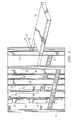
- FIG. 1illustrates a perspective view of a rack including plurality of rack rails and a top and a bottom support;
- FIG. 2illustrates an exploded view of a component installed in the U space of the rack, with portions removed;
- FIG. 3is a cross sectional view of a rack illustrating dedicated space and non-dedicated space
- FIG. 4illustrates a perspective view of an example embodiment of a component bracket coupled to a component mounted in the non-dedicated space of a rack;
- FIGS. 5 and 6illustrate exploded views of an example embodiment of a component bracket attaching an component to an interface opening in a non-dedicated space of a rack
- FIG. 7illustrates a flowchart for attaching an component to a rack rail in a non-dedicated space of a rack.
- FIGS. 1 through 7where like numbers are used to indicate like and corresponding parts.
- an information handling systemmay include any instrumentality or aggregate of instrumentalities operable to compute, classify, process, transmit, receive, retrieve, originate, switch, store, display, manifest, detect, record, reproduce, handle, or utilize any form of information, intelligence, or data for business, scientific, control, or other purposes.
- an information handling systemmay be a personal computer, a network storage device, or any other suitable device and may vary in size, shape, performance, functionality, and price.
- the information handling systemmay include random access memory (RAM), one or more processing resources such as a central processing unit (CPU) or hardware or software control logic, ROM, and/or other types of nonvolatile memory.
- Additional components of the information handling systemmay include one or more disk drives, one or more network ports for communicating with external devices, as well as various input and output (I/O) devices, such as a keyboard, a mouse, and a video display.
- the information handling systemmay also include one or more buses operable to transmit communications between the various hardware components.
- FIG. 1illustrates a perspective view of an example embodiment of a rack indicated generally at 10 .
- rack 10may include a plurality of rack rails 12 , top 17 , and bottom 16 .
- Rack rails 12are preferably disposed in a vertical position and connected to horizontally positioned top 17 and bottom 16 .
- rails 12may be positioned substantially horizontally and supported by end components.
- Rack 10may be arranged in a variety of configurations including, but not limited to, an open frame, an enclosed frame, and a stand-alone unit.
- Rack 10preferably houses information handling system components 15 and 19 .
- Rack 10may be enclosed by enclosure panels (not expressly shown) and may further form a cabinet enclosure with varying depths and heights.
- Enclosure panelsmay include side panels, top panels, and bottom panels attached to the plurality of rack rails 12 .
- Panelsmay be formed from any suitable material to enclose rack 10 within a cabinet.
- enclosure panelsmay be made from perforated metal plates to provide ventilation for components 15 and 19 placed within rack 10 .
- rack 10may be formed from high strength members to support this additional weight.
- rack 10may be made of twelve-gauge steel to provide support for placing up to two thousand pounds of components 15 in rack rails 12 .
- Rack 10may further include a variety of additional rail components (not expressly shown) such as side rails, cross rails, top rails, and bottom rails for providing additional support to rack 10 .
- additional rail componentssuch as side rails, cross rails, top rails, and bottom rails for providing additional support to rack 10 .
- rack rails 12are used for mounting a variety of components to rack 10 , such as components 15 and 19 .
- component 15is sized to be disposed in a dedicated or so-called U-space within rack 10 .
- Components 19are disposed in non-dedicated or Zero-U space within rack 10 .
- Components 15 and/or 19may include server, computer, disk drive, tape drive, raid drive, power distributions unit, switch, router, or other suitable components for use in an information handling system.
- rack rails 12may include a first standard interface such as an EIA RS-310 standard compliant interface for mounting components within a dedicated portion of rack 10 (as shown in FIG. 3, below.
- rack 10preferably includes a second standard interface, such as a 25 mm pitch interface for mounting components within non-dedicated portions of rack 10 .
- FIG. 2illustrates a perspective view of an example embodiment of rack rails 12 , with portions removed, depicting different standard interfaces for mounting components 15 in rack 10 .
- Each rack rail 12includes at least one standard interface used to attach a variety of components 15 to rack 10 .
- a standard interfaceincludes a repeating pattern or common connection points or apertures to facilitate the attachment of devices such as component 15 to rack 10 .
- rack rails 12may include a first standard interface that conforms to an Electronic Industry Association (EIA) standard such as EIA standard RS-310 for mounting component 15 in rack 10 .
- EIAElectronic Industry Association
- Rack 10includes at least two sets of rack rails 12 that include interfaces that conform to an EIA RS-310 standard. This standard defines vertical spacing of the rack into 1.75 inch increments, also known as “U's”. Each U 13 consists of three mounting apertures. Also in accordance with the EIA RS-310 standard, the distance between a pair of rack rails 12 is typically at nineteen (19) inches. Components 15 are often sized according to the number of U's within a rack they will require, such as a 1U server.
- Racksmay further be defined according to the number of U's that correspond to the height of the EIA RS-310 interface portion of the rack, such as a 24U rack, 42U rack or other suitable multiple.
- a 42U rackmay be an enclosed rack having forty-two 1.75-inch spaces for attaching components 15 .
- Each U location 13 on rack rail 12may include three mounting points for attaching a component 15 (or an arm or slide component formed to support component 15 ) to rack rail 12 .
- the interior space within rack 10 that may house component 15 and support by first standard interface 13is defined to be dedicated interior space or U-space.
- Rack rails 12may further include second standard interface 14 for providing attachment locations for various hardware and components 19 to be placed in rack 10 .
- Second standard interface 14may be used to attach components in areas within the rack but not associated with the dedicated rack space.
- rails 12also include second standard interface 14 for mounting components 19 in non-dedicated or non-U space within rack 10 .
- second standard interface 14is a twenty-five millimeter pitch interface that provides interface openings 40 at twenty-five millimeter intervals. In alternative embodiments, another suitable standard interface may be used.
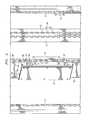
- FIG. 3illustrates a cross-sectional view of rack 10 showing an example embodiment of dedicated space 24 and non-dedicated space 25 .
- First standard interface 13(as shown in FIG. 2) defines dedicated space or U-space 24 , for disposing components 15 within rack 10 . Because components 15 often do not extend to the entire depth of rack 10 , a zero-U space or non-dedicated space 25 may remain behind component 15 . Additional non-dedicated space includes areas on the sides, bottom, and top of rack 10 . In some instances this space may be used for routing cables or permitting various electrical interconnections between components 15 and 19 . However, in other instances, components 19 may be installed in non-dedicated space 25 . In operation, any remaining space in rack 10 not occupied by a component 15 may be considered to be non-dedicated space 25 .
- FIG. 4illustrates a perspective view of component bracket 30 coupled to component 19 mounted in non-dedicated space 25 of rack 10 .
- Component bracket 30may be coupled to component 19 for attaching to interface opening 40 located in rack rail 12 .
- Component bracket 30may be retained in rack 10 by engaging hook 32 to interface opening 40 and using latch mechanism 34 to prevent disengagement of hook 32 from rack rail 12 .
- component bracket 30engages a portion of rack rail 12 to hold component 15 within non-dedicated space 25 .
- U space 24 in rack 10may be populated with other information handling components.
- a power distribution unit (PDU)may be coupled with component bracket 30 for placement in non-dedicated space 25 , thus permitting additional servers to be placed in the U space of rack 10 .
- components 19 installed in non-dedicated space 24may include peripherals, fans, power distribution units, switches, routers, or any other suitable component for placing in non-dedicated space 25 .
- components 19 installed in non-dedicated space 24may include peripherals, fans, power distribution units, switches, routers, or any other suitable component for placing in non-dedicated space 25 .
- several power distribution unitsare located along rack rail 12 in non-dedicated space 24 to provide multiple electrical outlets for components 15 and installed in either U space 24 or non-dedicated space 25 .
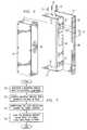
- FIGS. 5 and 6illustrate exploded views of an example embodiment of component bracket 30 used for attaching component 19 to interface opening 40 in non-dedicated space 25 of rack 10 .
- Component bracket 30is formed to couple to a an appropriate standard interface.
- component bracket 30is formed to couple to second standard interface 14 .
- component bracket 30may be formed from a similar material as rack rail 12 , but may be formed from any suitable material operable to support component 19 .
- component bracket 30may be stamped and shaped from thin-gauge steel.
- component bracket 30attaches to component 19 using fasteners 33 .
- component bracket 30may include apertures 31 with threaded screws 33 for attaching component bracket 30 to component 15 .
- component bracket 30may be coupled to component 19 by other suitable fasteners.
- component bracket 32may be integrated into the exterior housing of component 19 .
- Component bracket 30preferably includes hook 32 and latching mechanism 34 .
- Hook 32extends out from component bracket 30 in the opposite direction from attached component 19 to engage second interface 14 .
- hook 32may extend from component bracket 30 in a downward-facing, generally L-shaped configuration such that hook 32 extends through and engages rack rail 12 at interface opening 40 to mount component 15 in place.
- component bracket 30includes more than one hook 32 for attaching component bracket 30 to second interface 14 .
- component bracketmay include only a single hook.
- the present embodimentsalso provides for a dual set of hooks, disposed side-by-side to allow for alternate attachment orientations for component bracket 30 with respect to interface 14 .
- the dual set of attachment hooks 32permits component bracket 30 to utilize non-dedicated space on either side of rack 10 .
- component bracket 30may be formed with two sets of symmetrical hooks 32 to provide for a left side attachment or a right side attachment using two hooks 32 for each side at one time.
- Latch mechanism 34is preferably included for attaching component bracket 30 to interface 14 .
- latch 34prevents hook 32 from disengaging from interface opening 40 while latch 34 is engaged with interface 14 .
- hook 32may be un-hooked, thereby allowing removal of component bracket 30 from rail 12 .
- latch mechanism 34allows component bracket 30 to be detachably coupled to rack rail 12 .
- hook 32engages opening 40 by sliding along rack rail 12 .
- hook 32is space apart from latch mechanism 34 such that as hook 32 engages an opening 40 , latch mechanism 34 may automatically engage another opening 40 along rack rail 12 . In this manner, latch mechanism 34 secures the one or more hooks 32 of component bracket 30 to rail 12 until latch mechanism 34 is depressed to allow for removal.
- latch mechanism 34may be coupled to component bracket 30 with rivet 46 .
- Latch mechanismmay further include longitudinal spring 45 attached to stop 44 .
- Depressing stop 44 in direction of arrow 47may allow for component bracket 30 to freely slide along rack rail 12 permitting attachment to or removal from rack rail 12 .
- longitudinal spring 45applies force to stop 44 , thereby positioning stop 44 into opening 40 and substantially preventing further movement of component bracket 30 with respect to rail 12 .
- stop 44may protrude into second opening 40 as hook 32 engages first opening 40 of rack rail 12 .
- stop 44 in combination with longitudinal spring 45may prevent hook 32 from disengaging rack rail 12 .
- latch mechanism 34may engage any suitable portion of rack 10 to prevent hook 32 from being removed from interface opening 40 .
- component bracket 30may be formed over one or more sides of component 15
- component bracket 30may include bracket opening 36 to provide expose a section of component 19 .
- Bracket opening 36may be formed as notch or other suitable opening to expose a part of component 19 .
- the exposed portion of component 19may be used to access component 19 for tasks including inspecting or attaching a device to component 19 .
- exposing a section of component 19may permit the connection of an electrical cable to component port 39 of component 19 .
- Component port 39may include a connection for an electrical cable, a communications port, or a power cable.
- rack rails 12may include a rack relief 38 formed in the rails.
- Rack relief 38may provide access to component 15 via bracket opening 36 while attached to rack 10 .
- Rack relief 38may include any opening, notch, break, deviation, or any suitable void length of rail member that allows access to component 15 .
- rack relief 38may include a notch that may align with bracket opening 36 to permit cables such as power cables or communication cables to be attached at component port 39 .
- FIG. 7illustrates a flowchart for attaching component 15 to rack rails 12 in non-dedicated space 25 of rack 10 .
- component 15may be associated with component bracket 30 for placement in rack 10 containing a plurality of rack rails 12 .
- Component bracket 30may be attached to component 15 such that the orientation of component 15 in rack 10 remains in non-dedicated space 25 when mounted to rack rails 12 .
- component bracket 30may be aligned with first interface opening 40 in rack 10 .
- Component bracket 30 including hook 32 and latch mechanism 34may be placed in alignment with second standard interface 14 such that one or more hooks 32 may protrude into rack rail 12 at one or more respective interface openings 40 .
- interface opening 40is be formed according to a standard pitch spacing such as a twenty-five millimeter pitch spacing.
- Component bracket 30aligns with rack rail 12 such that component 19 is wholly placed within non-dedicated space 25 of rack 10 .
- component bracket 30 with attached component 19may be positioned adjacent to rack rail 12 , allowing hook 32 to extend through first interface opening 40 .
- component bracket 30includes more than one hook 32
- component bracket 30is positioned to engage the more than one hook in openings 40 .
- component bracket 30preferably slides adjacent to rack rail 12 to engage hook 32 with interface opening 40 .
- longitudinal spring 45urges stop 44 into another opening 40 .
- Component 19 and component bracketare then substantially secured to rack rail 12 .
- component bracket 30may be retained in position until latch mechanism 34 is released to allow component bracket 30 to slide.
- stop 44 of latch mechanism 34may be depressed until stop 44 is retracted from second interface opening 40 . With component bracket 30 free to slide, component bracket 30 may be disengaged rack rail 12 .
Landscapes
- Engineering & Computer Science (AREA)
- Computer Hardware Design (AREA)
- General Engineering & Computer Science (AREA)
- Microelectronics & Electronic Packaging (AREA)
- Drawers Of Furniture (AREA)
Abstract
Description
Claims (19)
Priority Applications (1)
| Application Number | Priority Date | Filing Date | Title |
|---|---|---|---|
| US10/206,302US6769551B2 (en) | 2002-07-26 | 2002-07-26 | System and method for utilizing non-dedicated rack space |
Applications Claiming Priority (1)
| Application Number | Priority Date | Filing Date | Title |
|---|---|---|---|
| US10/206,302US6769551B2 (en) | 2002-07-26 | 2002-07-26 | System and method for utilizing non-dedicated rack space |
Publications (2)
| Publication Number | Publication Date |
|---|---|
| US20040016708A1 US20040016708A1 (en) | 2004-01-29 |
| US6769551B2true US6769551B2 (en) | 2004-08-03 |
Family
ID=30770257
Family Applications (1)
| Application Number | Title | Priority Date | Filing Date |
|---|---|---|---|
| US10/206,302Expired - LifetimeUS6769551B2 (en) | 2002-07-26 | 2002-07-26 | System and method for utilizing non-dedicated rack space |
Country Status (1)
| Country | Link |
|---|---|
| US (1) | US6769551B2 (en) |
Cited By (39)
| Publication number | Priority date | Publication date | Assignee | Title |
|---|---|---|---|---|
| US20040080244A1 (en)* | 2002-10-28 | 2004-04-29 | Lowther Robert J. | Expandable server cabinet |
| US20050083651A1 (en)* | 2002-05-31 | 2005-04-21 | Smith John V. | Method and apparatus for rack mounting computer components |
| US20070130879A1 (en)* | 2005-12-12 | 2007-06-14 | Inventec Corporation | Fastening member |
| US20070231104A1 (en)* | 2006-03-30 | 2007-10-04 | Inventec Corporation | Track fixture |
| US20080291656A1 (en)* | 2007-05-22 | 2008-11-27 | Mcdowell Darrel L | Cable management system with inspection window |
| US20090134755A1 (en)* | 2007-10-01 | 2009-05-28 | Harold Dean Lakoduk | Configurable Enclosure for Electronics Components |
| US20090218461A1 (en)* | 2008-02-28 | 2009-09-03 | Nec Infrontia Corporation | Base assembly capable of reducing the number of assembling steps |
| US20090261051A1 (en)* | 2008-04-21 | 2009-10-22 | International Business Machines Corporation | Toolless Rail Mounting For A Computer System Rack |
| USD610847S1 (en)* | 2007-05-25 | 2010-03-02 | Herman Miller, Inc. | Frame for furniture support |
| US20100110621A1 (en)* | 2008-10-31 | 2010-05-06 | Liebert Corporation | Rack with vertical mounting providing room for rack pdu |
| US20110069436A1 (en)* | 2009-09-18 | 2011-03-24 | Hon Hai Precision Industry Co., Ltd. | Server cabinet and computer server system using same |
| US20110114575A1 (en)* | 2009-11-16 | 2011-05-19 | HONG FU JIN PRECISION INDUSTY (ShenZhen) CO. LTD. | Rack enclosure |
| US20110114576A1 (en)* | 2009-11-13 | 2011-05-19 | Hong Fu Jin Precision Industry (Shenzhen) Co., Ltd. | Rack enclosure |
| US20120020016A1 (en)* | 2010-02-11 | 2012-01-26 | Liang-Ho Cheng | Tower computer system |
| US20120062083A1 (en)* | 2010-09-10 | 2012-03-15 | Lewis Ii Richard Evans | Rail mounting clamp for electronic equipment enclosure |
| US20120112610A1 (en)* | 2010-11-10 | 2012-05-10 | Abb Ag | Electrical switchgear and distribution cabinet |
| US20120201002A1 (en)* | 2011-02-07 | 2012-08-09 | Dell Products L.P. | System and method for an optimizable rack solution |
| US20130314848A1 (en)* | 2012-05-28 | 2013-11-28 | Hon Hai Precision Industry Co., Ltd. | Power distribution unit and server cabinet with the power distribution unit |
| US20140085790A1 (en)* | 2012-09-21 | 2014-03-27 | Hon Hai Precision Industry Co., Ltd. | Server rack |
| US20140118886A1 (en)* | 2012-10-31 | 2014-05-01 | Jon Brian Ehlen | Rack structure-mounted power distribution unit |
| US20140159552A1 (en)* | 2012-12-11 | 2014-06-12 | Panduit Corp. | Equipment Segregation Unit For An Industrial Control Panel |
| US8901438B2 (en) | 2010-09-10 | 2014-12-02 | Chatsworth Products, Inc. | Electronic equipment cabinet structure |
| US8901418B2 (en) | 2012-06-25 | 2014-12-02 | Panduit Corp. | Server cabinet |
| US8925739B2 (en)* | 2012-07-26 | 2015-01-06 | Lenovo Enterprise Solutions (Singapore) Pte. Ltd. | High-capacity computer rack with rear-accessible side bays |
| US9055677B2 (en) | 2010-09-10 | 2015-06-09 | Chatsworth Products, Inc. | Cable pass-through panel for electronic equipment enclosure |
| US9144175B2 (en) | 2012-06-25 | 2015-09-22 | Panduit Corp. | Electronics cabinet |
| US9351427B2 (en) | 2013-12-17 | 2016-05-24 | Chatsworth Products, Inc. | Electronic equipment enclosure |
| US9690065B2 (en) | 2014-09-12 | 2017-06-27 | Panduit Corp. | High density fiber enclosure and method |
| US20180084907A1 (en)* | 2016-09-24 | 2018-03-29 | King Slide Works Co., Ltd. | Rail mounting adapter assembly for rack |
| US9943003B2 (en) | 2012-06-25 | 2018-04-10 | Panduit Corp. | Electronics cabinet |
| US10182651B2 (en) | 2016-01-30 | 2019-01-22 | Cooper Technologies Company | Panel for equipment rack |
| US10215944B2 (en) | 2016-06-30 | 2019-02-26 | Panduit Corp. | Modular fiber optic tray |
| US10356931B1 (en)* | 2017-05-26 | 2019-07-16 | King Slide Works Co., Ltd. | Rack mounting system |
| US10595442B2 (en) | 2013-01-11 | 2020-03-17 | Chatsworth Products, Inc. | Data processing equipment structure |
| EP4002969A1 (en)* | 2020-11-18 | 2022-05-25 | CommScope Design & Integration UK Limited | Universal equipment rack for telecommunications cabinets |
| US20230029230A1 (en)* | 2021-07-26 | 2023-01-26 | King Slide Works Co., Ltd. | Supporting device |
| CN115701754A (en)* | 2021-08-02 | 2023-02-10 | 川湖科技股份有限公司 | Support device |
| US20240196557A1 (en)* | 2022-12-09 | 2024-06-13 | Dell Products L.P. | Aggregate rail system for a rack assembly |
| US12289857B1 (en)* | 2024-03-19 | 2025-04-29 | Martas Precision Slide Co., Ltd. | Bracket for open rack |
Families Citing this family (45)
| Publication number | Priority date | Publication date | Assignee | Title |
|---|---|---|---|---|
| US20040189162A1 (en)* | 2003-03-28 | 2004-09-30 | Davis Brooks L. | Tool-less attachment and removal of components in a computer enclosure |
| US20040201335A1 (en)* | 2003-03-28 | 2004-10-14 | Brooks Davis | Universal computer enclosure |
| US20040189161A1 (en)* | 2003-03-28 | 2004-09-30 | Davis Brooks I. | Zero rack unit space utilization |
| US7382623B2 (en)* | 2003-06-11 | 2008-06-03 | Dell Products L.P. | Method and system for coupling a chassis to a rail |
| US7196900B2 (en)* | 2004-05-21 | 2007-03-27 | Server Technology, Inc. | Adaptable rack mountable power distribution apparatus |
| US7293666B2 (en)* | 2004-11-17 | 2007-11-13 | American Power Conversion Corporation | Equipment enclosure kit and assembly method |
| US7472970B2 (en)* | 2004-11-17 | 2009-01-06 | American Power Conversion Corporation | Equipment enclosure kit and assembly method |
| US7355859B2 (en)* | 2005-03-08 | 2008-04-08 | Hewlett-Packard Development Company, L.P. | DC power port in a rack |
| US20060232879A1 (en)* | 2005-04-18 | 2006-10-19 | Primera Technology, Inc. | Rack mountable data recording assembly |
| WO2007095164A2 (en)* | 2006-02-13 | 2007-08-23 | Miteq, Inc. | Rack-mounting system for improving redundancy |
| US20070235264A1 (en)* | 2006-02-24 | 2007-10-11 | Mechtronics Corporation | Modular merchandising system |
| US9198324B1 (en)* | 2006-02-28 | 2015-11-24 | Gorgius L. Yousif | Modular mount rack frame |
| US10271449B1 (en)* | 2006-02-28 | 2019-04-23 | Gorgius L Yousif | Mount rack frame |
| EP2238492A2 (en) | 2008-01-07 | 2010-10-13 | Chatsworth Products, Inc. | Apparatus and method for organizing cables in a cabinet |
| US8263867B2 (en) | 2008-01-07 | 2012-09-11 | Chatsworth Products, Inc. | Cable management accessories |
| SE535066C2 (en) | 2008-01-07 | 2012-04-03 | Chatsworth Prod Inc | Vertical cable management device |
| US20090283488A1 (en)* | 2008-05-19 | 2009-11-19 | Chatsworth Products, Inc. | Seismically hardened two-post electronic equipment rack |
| US9836376B2 (en) | 2009-09-24 | 2017-12-05 | Contec, Llc | Method and system for automated test of end-user devices |
| US8490799B2 (en)* | 2009-12-31 | 2013-07-23 | Telect Inc. | Six-post telecommunications equipment rack |
| CN102137553A (en)* | 2010-01-25 | 2011-07-27 | 鸿富锦精密工业(深圳)有限公司 | Cabinet and assembly method thereof |
| US20110187248A1 (en)* | 2010-02-02 | 2011-08-04 | Jui-Chien Kao | Tool cabinet |
| CN102378540A (en)* | 2010-08-18 | 2012-03-14 | 鸿富锦精密工业(深圳)有限公司 | Server cabinet framework |
| TWI409020B (en)* | 2010-12-23 | 2013-09-11 | Delta Electronics Inc | Data processing equipment and power matching mechanism with methods using same |
| US8582299B1 (en)* | 2010-12-23 | 2013-11-12 | Amazon Technologies, Inc. | System with movable computing devices |
| TW201227236A (en)* | 2010-12-23 | 2012-07-01 | Delta Electronics Inc | Data processing equipment and power matching mechanism with methods using same |
| US9709333B2 (en)* | 2014-05-01 | 2017-07-18 | Ford Global Technologies Llc | Multipurpose rack for processing parts through multiple manufacturing processes |
| US20170126536A1 (en) | 2015-10-30 | 2017-05-04 | Contec, Llc | Hardware Architecture for Universal Testing System: Cable Modem Test |
| US10122611B2 (en) | 2015-09-25 | 2018-11-06 | Contec, Llc | Universal device testing interface |
| US9900116B2 (en) | 2016-01-04 | 2018-02-20 | Contec, Llc | Test sequences using universal testing system |
| US9810735B2 (en) | 2015-09-25 | 2017-11-07 | Contec, Llc | Core testing machine |
| US10320651B2 (en) | 2015-10-30 | 2019-06-11 | Contec, Llc | Hardware architecture for universal testing system: wireless router test |
| US9992084B2 (en) | 2015-11-20 | 2018-06-05 | Contec, Llc | Cable modems/eMTAs under test |
| US9960989B2 (en) | 2015-09-25 | 2018-05-01 | Contec, Llc | Universal device testing system |
| US10291959B2 (en) | 2015-09-25 | 2019-05-14 | Contec, Llc | Set top boxes under test |
| US9838295B2 (en) | 2015-11-23 | 2017-12-05 | Contec, Llc | Wireless routers under test |
| US10277497B2 (en) | 2015-09-25 | 2019-04-30 | Contec, Llc | Systems and methods for testing electronic devices using master-slave test architectures |
| WO2017074872A1 (en)* | 2015-10-30 | 2017-05-04 | Contec, Llc | Universal testing system architecture |
| US9900113B2 (en)* | 2016-02-29 | 2018-02-20 | Contec, Llc | Universal tester hardware |
| US10349553B2 (en)* | 2016-03-22 | 2019-07-09 | Commscope Technologies Llc | Adjustable rack for electronics cabinet |
| US10462456B2 (en) | 2016-04-14 | 2019-10-29 | Contec, Llc | Automated network-based test system for set top box devices |
| US10779056B2 (en) | 2016-04-14 | 2020-09-15 | Contec, Llc | Automated network-based test system for set top box devices |
| US10284456B2 (en) | 2016-11-10 | 2019-05-07 | Contec, Llc | Systems and methods for testing electronic devices using master-slave test architectures |
| US9955607B1 (en)* | 2016-12-21 | 2018-04-24 | Mountain Stone Technologies, LLC | Electronic equipment vertical mount and stack rack |
| US10314395B2 (en)* | 2017-02-21 | 2019-06-11 | James E. McGhee, III | Pallet spacer system and method of use |
| CN109982540B (en)* | 2019-05-07 | 2024-02-06 | 苏州浪潮智能科技有限公司 | A cabinet compatible with 19-inch and 21-inch servers |
Citations (56)
| Publication number | Priority date | Publication date | Assignee | Title |
|---|---|---|---|---|
| US3133768A (en) | 1960-01-11 | 1964-05-19 | Markline Electronic Products I | Extensible chassis slide |
| US3680711A (en) | 1969-04-30 | 1972-08-01 | Suburban Metal Ind Ltd | Decking and shoring beam |
| US3697034A (en) | 1970-01-12 | 1972-10-10 | Irving W Shell | Locking shelf bracket support structure |
| US4184726A (en) | 1978-04-21 | 1980-01-22 | Norlin Industries, Inc. | Reversible mounting bracket |
| US4406374A (en) | 1981-08-12 | 1983-09-27 | Myco, Inc. | Locking device for display rack |
| US4731029A (en) | 1986-10-23 | 1988-03-15 | Mega/Erg Inc. | Wire and cable manager |
| US4931907A (en) | 1989-03-30 | 1990-06-05 | Tandem Computers Incorporated | Electric module latch assembly |
| US5018052A (en) | 1990-01-08 | 1991-05-21 | Sun Microsystems, Inc. | Cable management apparatus for a computer workstation housing |
| US5216579A (en) | 1992-01-29 | 1993-06-01 | International Business Machines Corporation | Rack based packaging system for computers with cable, cooling and power management module |
| US5460441A (en) | 1994-11-01 | 1995-10-24 | Compaq Computer Corporation | Rack-mounted computer apparatus |
| US5505533A (en) | 1994-01-10 | 1996-04-09 | Artecon | Rackmount for computer and mass storage enclosure |
| US5546277A (en) | 1994-05-24 | 1996-08-13 | Sun Microsystems, Inc. | Computer component torsional latching mechanism and method |
| US5571256A (en)* | 1994-10-25 | 1996-11-05 | Compaq Computer Corporation | Server drawer slide mount apparatus for a rack-mounted computer system |
| US5579924A (en) | 1994-12-13 | 1996-12-03 | Dell Usa, L.P. | Accessory storage system and apparatus |
| US5655738A (en) | 1995-06-07 | 1997-08-12 | Ragsdale; Thomas Ray | Cable management device |
| US5684671A (en) | 1995-08-22 | 1997-11-04 | Sequent Computer Systems, Inc. | Packaging architecture for a data server |
| US5791498A (en) | 1997-01-21 | 1998-08-11 | Dell U.S.A., L.P. | Rack mount mechanism having an angled bar-nut |
| US5833337A (en) | 1997-05-09 | 1998-11-10 | Sequent Computer Systems, Inc. | Self-retaining rack slide |
| US5850925A (en) | 1996-11-26 | 1998-12-22 | Dell Usa, L.P. | Rack mount mechanism for mid-tower type computer enclosure |
| US5884609A (en) | 1994-05-09 | 1999-03-23 | Nissan Motor Co., Ltd. | Air/fuel ratio control apparatus |
| US5890602A (en) | 1997-06-27 | 1999-04-06 | Dell Usa, L.P. | Demonstrative packaging for rack mount hardware |
| US5893593A (en) | 1996-07-10 | 1999-04-13 | Mitsui Kinzoku Kogyo Kabushiki Kaisha | Latch device used in vehicle door |
| US5921402A (en) | 1998-04-27 | 1999-07-13 | Systems Manufacturing Corporation | Cable management track system |
| US5941621A (en) | 1997-02-28 | 1999-08-24 | Digital Equipment Corporation | Cabinet slide mounting bracket |
| US6011701A (en) | 1997-03-08 | 2000-01-04 | Dmt Gmbh, Feinwerktechnische Komplettlosungen | Component housing for integration with furniture |
| US6021047A (en) | 1997-10-24 | 2000-02-01 | Dell U.S.A., L,P. | Computer and a rack mount system and method for a computer |
| US6021909A (en) | 1998-11-13 | 2000-02-08 | Hewlett-Packard Company | Equipment enclosure rack support rail system |
| US6070841A (en) | 1998-03-13 | 2000-06-06 | Advertising Display Company | Universal sidekick mount bracket |
| US6070957A (en) | 1997-03-25 | 2000-06-06 | Rittal-Werk Rudolf Loh Gmbh & Co. Kg | Device for fastening a support rail on frame legs and mounting panels of a switchgear cabinet |
| US6071742A (en) | 1997-03-05 | 2000-06-06 | Board Of Regents Of The University Of Nebraska | Coxsackie virus as a vector for delivery of anti-inflammatory cytokines |
| US6070742A (en) | 1998-10-28 | 2000-06-06 | Dell Usa, L.P. | Multi-segment, nesting, low profile cable management arm |
| US6076198A (en) | 1997-10-24 | 2000-06-20 | T. Eliot,Inc. | Tubular film dispensing apparatus |
| US6095345A (en) | 1998-10-22 | 2000-08-01 | Dell Usa L P | Electronics rack alignment structures |
| US6142590A (en) | 1999-04-05 | 2000-11-07 | Central Industrial Supply Company | Two U vertical height keyboard and flatscreen drawer for a server system rack |
| US6181549B1 (en) | 1997-06-24 | 2001-01-30 | Dell Products, L.P. | Chassis retaining system for an electronics rack |
| US6185092B1 (en) | 1999-09-03 | 2001-02-06 | Compaq Computer Corporation | Computer system with in-line switchbox mounting |
| US6185098B1 (en) | 2000-01-31 | 2001-02-06 | Chatsworth Products, Inc. | Co-location server cabinet |
| US6223908B1 (en) | 1999-09-15 | 2001-05-01 | Homaco, Inc. | Adjustable communications equipment dual relay rack |
| US6230903B1 (en) | 1999-10-27 | 2001-05-15 | Hewlett-Packard Company | Snap-on rack slide mounting system |
| US6273534B1 (en) | 1999-11-05 | 2001-08-14 | Spacesaver Corporation | Shelving accessory mounting system for a cabinet assembly |
| US6297962B1 (en) | 2000-01-21 | 2001-10-02 | Dell Usa, L.P. | Apparatus for providing displacement to a slide mounted chassis in a rack |
| US6303864B1 (en) | 1999-12-22 | 2001-10-16 | Dell Products, L.P. | Connector arrangement and connecting method for cable management arms |
| US6305556B1 (en) | 2000-10-26 | 2001-10-23 | Hewlett-Packard Company | Cable management solution for rack-mounted computers |
| US6326547B1 (en) | 1999-11-02 | 2001-12-04 | Compaq Computer Corporation | Cable management system |
| US6365834B1 (en) | 2000-01-10 | 2002-04-02 | Ortronics, Inc. | Cable management rack with vertical wire guides |
| US6373721B2 (en) | 1999-08-30 | 2002-04-16 | 3Com Corporation | Cable management apparatus and method |
| US6398149B1 (en) | 2001-01-16 | 2002-06-04 | Ortronics, Inc. | Cable management system with adjustable cable spools |
| US6398041B1 (en)* | 1999-12-03 | 2002-06-04 | Hewlett-Packard Company | Snap system for retaining slide mounted rack system into multiple racks without tools |
| US6407933B1 (en) | 2000-10-18 | 2002-06-18 | Compaq Computer Corporation | Cable management system for use with rack mounted devices |
| US6422399B1 (en)* | 2000-11-21 | 2002-07-23 | Dell Products L.P. | Rack system and method having tool-less releasable arm assembly |
| US6429376B1 (en) | 2001-03-06 | 2002-08-06 | Adc Telecommunications, Inc. | Add-on trough for cable management rack |
| US6431668B1 (en)* | 1998-02-19 | 2002-08-13 | Edward Arnold Reddicliffe | Method of installing a telescopic shelf in a cabinet |
| US6435354B1 (en) | 2000-08-07 | 2002-08-20 | Dell Products L.P. | Cable management arm assembly |
| US20030026084A1 (en) | 2001-08-03 | 2003-02-06 | Lauchner Craig E. | Cable management arm with trough and breakaway feature |
| US6554142B2 (en)* | 2001-07-27 | 2003-04-29 | Dell Products L.P. | Variable mount rack system arm assembly |
| US20030123832A1 (en) | 2000-11-28 | 2003-07-03 | International Business Machines Corporation | Cable management device for mixed media |
- 2002
- 2002-07-26USUS10/206,302patent/US6769551B2/ennot_activeExpired - Lifetime
Patent Citations (56)
| Publication number | Priority date | Publication date | Assignee | Title |
|---|---|---|---|---|
| US3133768A (en) | 1960-01-11 | 1964-05-19 | Markline Electronic Products I | Extensible chassis slide |
| US3680711A (en) | 1969-04-30 | 1972-08-01 | Suburban Metal Ind Ltd | Decking and shoring beam |
| US3697034A (en) | 1970-01-12 | 1972-10-10 | Irving W Shell | Locking shelf bracket support structure |
| US4184726A (en) | 1978-04-21 | 1980-01-22 | Norlin Industries, Inc. | Reversible mounting bracket |
| US4406374A (en) | 1981-08-12 | 1983-09-27 | Myco, Inc. | Locking device for display rack |
| US4731029A (en) | 1986-10-23 | 1988-03-15 | Mega/Erg Inc. | Wire and cable manager |
| US4931907A (en) | 1989-03-30 | 1990-06-05 | Tandem Computers Incorporated | Electric module latch assembly |
| US5018052A (en) | 1990-01-08 | 1991-05-21 | Sun Microsystems, Inc. | Cable management apparatus for a computer workstation housing |
| US5216579A (en) | 1992-01-29 | 1993-06-01 | International Business Machines Corporation | Rack based packaging system for computers with cable, cooling and power management module |
| US5505533A (en) | 1994-01-10 | 1996-04-09 | Artecon | Rackmount for computer and mass storage enclosure |
| US5884609A (en) | 1994-05-09 | 1999-03-23 | Nissan Motor Co., Ltd. | Air/fuel ratio control apparatus |
| US5546277A (en) | 1994-05-24 | 1996-08-13 | Sun Microsystems, Inc. | Computer component torsional latching mechanism and method |
| US5571256A (en)* | 1994-10-25 | 1996-11-05 | Compaq Computer Corporation | Server drawer slide mount apparatus for a rack-mounted computer system |
| US5460441A (en) | 1994-11-01 | 1995-10-24 | Compaq Computer Corporation | Rack-mounted computer apparatus |
| US5579924A (en) | 1994-12-13 | 1996-12-03 | Dell Usa, L.P. | Accessory storage system and apparatus |
| US5655738A (en) | 1995-06-07 | 1997-08-12 | Ragsdale; Thomas Ray | Cable management device |
| US5684671A (en) | 1995-08-22 | 1997-11-04 | Sequent Computer Systems, Inc. | Packaging architecture for a data server |
| US5893593A (en) | 1996-07-10 | 1999-04-13 | Mitsui Kinzoku Kogyo Kabushiki Kaisha | Latch device used in vehicle door |
| US5850925A (en) | 1996-11-26 | 1998-12-22 | Dell Usa, L.P. | Rack mount mechanism for mid-tower type computer enclosure |
| US5791498A (en) | 1997-01-21 | 1998-08-11 | Dell U.S.A., L.P. | Rack mount mechanism having an angled bar-nut |
| US5941621A (en) | 1997-02-28 | 1999-08-24 | Digital Equipment Corporation | Cabinet slide mounting bracket |
| US6071742A (en) | 1997-03-05 | 2000-06-06 | Board Of Regents Of The University Of Nebraska | Coxsackie virus as a vector for delivery of anti-inflammatory cytokines |
| US6011701A (en) | 1997-03-08 | 2000-01-04 | Dmt Gmbh, Feinwerktechnische Komplettlosungen | Component housing for integration with furniture |
| US6070957A (en) | 1997-03-25 | 2000-06-06 | Rittal-Werk Rudolf Loh Gmbh & Co. Kg | Device for fastening a support rail on frame legs and mounting panels of a switchgear cabinet |
| US5833337A (en) | 1997-05-09 | 1998-11-10 | Sequent Computer Systems, Inc. | Self-retaining rack slide |
| US6181549B1 (en) | 1997-06-24 | 2001-01-30 | Dell Products, L.P. | Chassis retaining system for an electronics rack |
| US5890602A (en) | 1997-06-27 | 1999-04-06 | Dell Usa, L.P. | Demonstrative packaging for rack mount hardware |
| US6021047A (en) | 1997-10-24 | 2000-02-01 | Dell U.S.A., L,P. | Computer and a rack mount system and method for a computer |
| US6076198A (en) | 1997-10-24 | 2000-06-20 | T. Eliot,Inc. | Tubular film dispensing apparatus |
| US6431668B1 (en)* | 1998-02-19 | 2002-08-13 | Edward Arnold Reddicliffe | Method of installing a telescopic shelf in a cabinet |
| US6070841A (en) | 1998-03-13 | 2000-06-06 | Advertising Display Company | Universal sidekick mount bracket |
| US5921402A (en) | 1998-04-27 | 1999-07-13 | Systems Manufacturing Corporation | Cable management track system |
| US6095345A (en) | 1998-10-22 | 2000-08-01 | Dell Usa L P | Electronics rack alignment structures |
| US6070742A (en) | 1998-10-28 | 2000-06-06 | Dell Usa, L.P. | Multi-segment, nesting, low profile cable management arm |
| US6021909A (en) | 1998-11-13 | 2000-02-08 | Hewlett-Packard Company | Equipment enclosure rack support rail system |
| US6142590A (en) | 1999-04-05 | 2000-11-07 | Central Industrial Supply Company | Two U vertical height keyboard and flatscreen drawer for a server system rack |
| US6373721B2 (en) | 1999-08-30 | 2002-04-16 | 3Com Corporation | Cable management apparatus and method |
| US6185092B1 (en) | 1999-09-03 | 2001-02-06 | Compaq Computer Corporation | Computer system with in-line switchbox mounting |
| US6223908B1 (en) | 1999-09-15 | 2001-05-01 | Homaco, Inc. | Adjustable communications equipment dual relay rack |
| US6230903B1 (en) | 1999-10-27 | 2001-05-15 | Hewlett-Packard Company | Snap-on rack slide mounting system |
| US6326547B1 (en) | 1999-11-02 | 2001-12-04 | Compaq Computer Corporation | Cable management system |
| US6273534B1 (en) | 1999-11-05 | 2001-08-14 | Spacesaver Corporation | Shelving accessory mounting system for a cabinet assembly |
| US6398041B1 (en)* | 1999-12-03 | 2002-06-04 | Hewlett-Packard Company | Snap system for retaining slide mounted rack system into multiple racks without tools |
| US6303864B1 (en) | 1999-12-22 | 2001-10-16 | Dell Products, L.P. | Connector arrangement and connecting method for cable management arms |
| US6365834B1 (en) | 2000-01-10 | 2002-04-02 | Ortronics, Inc. | Cable management rack with vertical wire guides |
| US6297962B1 (en) | 2000-01-21 | 2001-10-02 | Dell Usa, L.P. | Apparatus for providing displacement to a slide mounted chassis in a rack |
| US6185098B1 (en) | 2000-01-31 | 2001-02-06 | Chatsworth Products, Inc. | Co-location server cabinet |
| US6435354B1 (en) | 2000-08-07 | 2002-08-20 | Dell Products L.P. | Cable management arm assembly |
| US6407933B1 (en) | 2000-10-18 | 2002-06-18 | Compaq Computer Corporation | Cable management system for use with rack mounted devices |
| US6305556B1 (en) | 2000-10-26 | 2001-10-23 | Hewlett-Packard Company | Cable management solution for rack-mounted computers |
| US6422399B1 (en)* | 2000-11-21 | 2002-07-23 | Dell Products L.P. | Rack system and method having tool-less releasable arm assembly |
| US20030123832A1 (en) | 2000-11-28 | 2003-07-03 | International Business Machines Corporation | Cable management device for mixed media |
| US6398149B1 (en) | 2001-01-16 | 2002-06-04 | Ortronics, Inc. | Cable management system with adjustable cable spools |
| US6429376B1 (en) | 2001-03-06 | 2002-08-06 | Adc Telecommunications, Inc. | Add-on trough for cable management rack |
| US6554142B2 (en)* | 2001-07-27 | 2003-04-29 | Dell Products L.P. | Variable mount rack system arm assembly |
| US20030026084A1 (en) | 2001-08-03 | 2003-02-06 | Lauchner Craig E. | Cable management arm with trough and breakaway feature |
Non-Patent Citations (21)
| Title |
|---|
| Cabling Reference for the HP NetServer LXr Pro, Chapter 4, pp. 46-48. |
| Compaq AlphaServer ES40 Rackmount System Installation Guide "Installing the Cable Management Arm," pp. 18-21. |
| Compaq ProLiant DL360 Ultra-Dense Server Deployment in Compaq Racks "4.6.3.2. Sliding-Rail Cable Management" pp. 89-90. |
| Compaq ProLiant ML350 Tower-to-Rack Conversion Guide 2 pp. |
| Figures filed in U.S. Pending patent Appl. Ser. No. 08/881,289 entitled "Chassis Retaining System for an Electronics Rack" by Mills et al., assigned to Dell USA L.P. (Client No. DC-01275), filed Jun. 24, 1997. |
| Figures filed in U.S. Pending patent Appl. Ser. No. 09/470,280 entitled "Connector Arrangement and Connecting Method for Cable Management Arms", assigned to Dell USA L.P. (Client No. DC-02095), filed Dec. 22, 1999. |
| Figures filed in U.S.Pending patent Appl. Ser. No. 09/518,841 entitled "Rack Mount Slide System Enabling Front, Top and Rear Access to a Rack Mounted Device" by Baddour et al., assigned to Dell Products L..P. (DC-02172), filed Mar. 3, 2000. |
| Figures for U.S. Pending Patent Application Serial No. 10/278,263 entitled "System and Method for Rack Cable Management" by Corey D. Hartman, et al.; Dell Products L.P. (DC-03714). |
| Figures for U.S. Pending Patent Application Serial No. 10/393,620 entitled "Tool-less Cable Management Attachment Bracket and Method of Use" by Tiffany J. Williams; Dell Products L.P. (DC-03692). |
| Figures for U.S. Pending Patent Application Serial No. 10/675,102 entitled "Cable Management Flip Tray Assembly" by Daniel G. Lee, et al.; Dell Products L.P. (DC-04824). |
| IBM Magstar MP 3570 Tape Subsystem OPerator Guide C-Series Models "Installing the Rack-Mounted 3570" pp. 86-98. |
| IBM Magstar MP 3570 Tape Subsystem Operator Guide C-Series Models Attaching SCSI and Power Cables to Model C21 (Single Drive with Single Host) 1 p. |
| J1478A-HP Cable Management Arm for LHx000r by Hewlett Packard 1 p. |
| Maintenance and Service Guide "illustrated Parts Catalog Chapter 1 -Illustrating the family of Compaq Rack-Mountable ProLiant 1500R Servers," 3 pp. |
| Netra t1 and Netra st D130 Rackmount Installation Chapter 2 pp. 9-14. |
| U.S. Pending patent Appl. Ser. No. 08/881,289 entitled "Chassis Retaining System for an Electronics Rack" by Mills et al., assigned to Dell USA L.P. (Client No. DC-01275), filed Jun. 24, 1997. |
| U.S. Pending patent Appl. Ser. No. 09/470,280 entitled "Connector Arrangement and Connecting Method for Cable Management Arms", assigned to Dell USA L.P. (Client No. DC-02095), filed Dec. 22, 1999. |
| U.S. Pending Patent Application Serial No. 10/278,263 entitled "System and Method for Rack Cable Management" by Corey D. Hartman, et al.; Dell Products L.P. (DC-03714). |
| U.S. Pending Patent Application Serial No. 10/393,620 entitled "Tool-less Cable Management Attachment Bracket and Method of Use" by Tiffany J. Williams; Dell Products L.P. (DC-03692). |
| U.S. Pending Patent Application Serial No. 10/675,102 entitled "Cable Management Flip Tray Assembly" by Daniel G. Lee, et al.; Dell Products L.P. (DC-04824). |
| U.S.Pending patent Appl. Ser. No. 09/518,841 entitled "Rack Mount Slide System Enabling Front, Top and Rear Access to a Rack Mounted Device" by Baddour et al., assigned to Dell Products L..P. (DC-02172), filed Mar. 3, 2000. |
Cited By (97)
| Publication number | Priority date | Publication date | Assignee | Title |
|---|---|---|---|---|
| US20050083651A1 (en)* | 2002-05-31 | 2005-04-21 | Smith John V. | Method and apparatus for rack mounting computer components |
| US7420805B2 (en)* | 2002-05-31 | 2008-09-02 | Verari Systems, Inc. | Method and apparatus for rack mounting computer components |
| US20040080244A1 (en)* | 2002-10-28 | 2004-04-29 | Lowther Robert J. | Expandable server cabinet |
| US20070130879A1 (en)* | 2005-12-12 | 2007-06-14 | Inventec Corporation | Fastening member |
| US20070231104A1 (en)* | 2006-03-30 | 2007-10-04 | Inventec Corporation | Track fixture |
| US7889516B2 (en) | 2007-05-22 | 2011-02-15 | At&T Intellectual Property I, L.P. | Cable management system with inspection window |
| US20080291656A1 (en)* | 2007-05-22 | 2008-11-27 | Mcdowell Darrel L | Cable management system with inspection window |
| USD610847S1 (en)* | 2007-05-25 | 2010-03-02 | Herman Miller, Inc. | Frame for furniture support |
| US20090134755A1 (en)* | 2007-10-01 | 2009-05-28 | Harold Dean Lakoduk | Configurable Enclosure for Electronics Components |
| US8714667B2 (en)* | 2007-10-01 | 2014-05-06 | Hoffman Enclosures, Inc. | Configurable enclosure for electronics components |
| US20090218461A1 (en)* | 2008-02-28 | 2009-09-03 | Nec Infrontia Corporation | Base assembly capable of reducing the number of assembling steps |
| US7975860B2 (en)* | 2008-04-21 | 2011-07-12 | International Business Machines Corporation | Toolless rail mounting for a computer system rack |
| US20090261051A1 (en)* | 2008-04-21 | 2009-10-22 | International Business Machines Corporation | Toolless Rail Mounting For A Computer System Rack |
| US20100110621A1 (en)* | 2008-10-31 | 2010-05-06 | Liebert Corporation | Rack with vertical mounting providing room for rack pdu |
| US20110069436A1 (en)* | 2009-09-18 | 2011-03-24 | Hon Hai Precision Industry Co., Ltd. | Server cabinet and computer server system using same |
| US8077455B2 (en)* | 2009-09-18 | 2011-12-13 | Hon Hai Precision Industry Co., Ltd. | Server cabinet and computer server system using same |
| US20110114576A1 (en)* | 2009-11-13 | 2011-05-19 | Hong Fu Jin Precision Industry (Shenzhen) Co., Ltd. | Rack enclosure |
| US20110114575A1 (en)* | 2009-11-16 | 2011-05-19 | HONG FU JIN PRECISION INDUSTY (ShenZhen) CO. LTD. | Rack enclosure |
| US8416567B2 (en)* | 2010-02-11 | 2013-04-09 | Liang-Ho Cheng | Tower computer system |
| US20120020016A1 (en)* | 2010-02-11 | 2012-01-26 | Liang-Ho Cheng | Tower computer system |
| US10237994B2 (en) | 2010-09-10 | 2019-03-19 | Chatsworth Products, Inc. | Vertical mounting rail with cable management features |
| US9055677B2 (en) | 2010-09-10 | 2015-06-09 | Chatsworth Products, Inc. | Cable pass-through panel for electronic equipment enclosure |
| US9781852B2 (en) | 2010-09-10 | 2017-10-03 | Chatsworth Products, Inc. | Cable pass-through panel for electronic equipment enclosure |
| US9642270B2 (en) | 2010-09-10 | 2017-05-02 | Chatsworth Products, Inc. | Rail seal for electronic equipment enclosure |
| US10653025B2 (en) | 2010-09-10 | 2020-05-12 | Chatsworth Products, Inc. | Cable pass-through panel for electronic equipment enclosure |
| US11039543B2 (en) | 2010-09-10 | 2021-06-15 | Chatsworth Products, Inc. | Vertical mounting rail with cable management features |
| US9814159B2 (en) | 2010-09-10 | 2017-11-07 | Chatsworth Products, Inc. | Rail seal for electronic equipment enclosure |
| US9408326B2 (en) | 2010-09-10 | 2016-08-02 | Chatsworth Products, Inc. | Electronic equipment cabinet structure |
| US11464123B2 (en) | 2010-09-10 | 2022-10-04 | Chatsworth Products, Inc. | Method of adapting an electronic equipment enclosure for cable management |
| US8787023B2 (en)* | 2010-09-10 | 2014-07-22 | Chatsworth Products, Inc. | Rail mounting clamp for electronic equipment enclosure |
| US20120062083A1 (en)* | 2010-09-10 | 2012-03-15 | Lewis Ii Richard Evans | Rail mounting clamp for electronic equipment enclosure |
| US8901438B2 (en) | 2010-09-10 | 2014-12-02 | Chatsworth Products, Inc. | Electronic equipment cabinet structure |
| US10588227B2 (en) | 2010-09-10 | 2020-03-10 | Chatsworth Products, Inc. | Vertical mounting rail with cable management features |
| US12108553B2 (en) | 2010-09-10 | 2024-10-01 | Chatsworth Products, Inc. | Cable pass-through panel for electronic equipment enclosure |
| US9980400B2 (en) | 2010-09-10 | 2018-05-22 | Chatsworth Products, Inc. | Rail seal for electronic equipment enclosure |
| US11792948B2 (en) | 2010-09-10 | 2023-10-17 | Chatsworth Products, Inc. | Cable pass-through panel for electronic equipment enclosure |
| US10178784B2 (en) | 2010-09-10 | 2019-01-08 | Chatsworth Products, Inc. | Rail seal for electronic equipment enclosure |
| US8746465B2 (en)* | 2010-11-10 | 2014-06-10 | Abb Ag | Electrical switchgear and distribution cabinet |
| US20120112610A1 (en)* | 2010-11-10 | 2012-05-10 | Abb Ag | Electrical switchgear and distribution cabinet |
| US20120201002A1 (en)* | 2011-02-07 | 2012-08-09 | Dell Products L.P. | System and method for an optimizable rack solution |
| US8976515B2 (en) | 2011-02-07 | 2015-03-10 | Dell Products L.P. | System and method for an optimizable rack solution |
| US8467175B2 (en)* | 2011-02-07 | 2013-06-18 | Dell Products L.P. | System and method for an optimizable rack solution |
| US8797751B2 (en)* | 2012-05-28 | 2014-08-05 | Hong Fu Jin Precision Industry (Shenzhen) Co., Ltd. | Power distribution unit and server cabinet with the power distribution unit |
| US20130314848A1 (en)* | 2012-05-28 | 2013-11-28 | Hon Hai Precision Industry Co., Ltd. | Power distribution unit and server cabinet with the power distribution unit |
| US8901418B2 (en) | 2012-06-25 | 2014-12-02 | Panduit Corp. | Server cabinet |
| US9510471B2 (en) | 2012-06-25 | 2016-11-29 | Panduit Corp. | Electronics cabinet |
| US9943003B2 (en) | 2012-06-25 | 2018-04-10 | Panduit Corp. | Electronics cabinet |
| US9648778B2 (en) | 2012-06-25 | 2017-05-09 | Panduit Corp. | Electronics cabinet |
| US9144175B2 (en) | 2012-06-25 | 2015-09-22 | Panduit Corp. | Electronics cabinet |
| US8925739B2 (en)* | 2012-07-26 | 2015-01-06 | Lenovo Enterprise Solutions (Singapore) Pte. Ltd. | High-capacity computer rack with rear-accessible side bays |
| US20140085790A1 (en)* | 2012-09-21 | 2014-03-27 | Hon Hai Precision Industry Co., Ltd. | Server rack |
| US9030810B2 (en)* | 2012-10-31 | 2015-05-12 | Facebook, Inc. | Rack structure-mounted power distribution unit |
| US20140118886A1 (en)* | 2012-10-31 | 2014-05-01 | Jon Brian Ehlen | Rack structure-mounted power distribution unit |
| US20140159552A1 (en)* | 2012-12-11 | 2014-06-12 | Panduit Corp. | Equipment Segregation Unit For An Industrial Control Panel |
| US9236717B2 (en)* | 2012-12-11 | 2016-01-12 | Panduit Corp. | Equipment segregation unit for an industrial control panel |
| US11647610B2 (en) | 2013-01-11 | 2023-05-09 | Chatsworth Products, Inc. | Modular thermal isolation barrier for data processing equipment structure |
| US12063758B2 (en) | 2013-01-11 | 2024-08-13 | Chatsworth Products, Inc. | Modular thermal isolation barrier for data processing equipment structure |
| US10595442B2 (en) | 2013-01-11 | 2020-03-17 | Chatsworth Products, Inc. | Data processing equipment structure |
| US11985799B2 (en) | 2013-12-17 | 2024-05-14 | Chatsworth Products, Inc. | Electronic equipment enclosure |
| US9949406B2 (en) | 2013-12-17 | 2018-04-17 | Chatsworth Products, Inc. | Electronic equipment enclosure |
| US11083108B2 (en) | 2013-12-17 | 2021-08-03 | Chatsworth Products, Inc. | Electronic equipment enclosure |
| US10356951B2 (en) | 2013-12-17 | 2019-07-16 | Chatsworth Products, Inc. | Electronic equipment enclosure |
| US10674634B2 (en) | 2013-12-17 | 2020-06-02 | Chatsworth Products, Inc. | Electronic equipment enclosure |
| US9351427B2 (en) | 2013-12-17 | 2016-05-24 | Chatsworth Products, Inc. | Electronic equipment enclosure |
| US9864158B2 (en) | 2014-09-12 | 2018-01-09 | Panduit Corp. | High density fiber enclosure and method |
| US10268013B2 (en) | 2014-09-12 | 2019-04-23 | Panduit Corp. | High density fiber enclosure and method |
| US11624888B2 (en) | 2014-09-12 | 2023-04-11 | Panduit Corp. | High density fiber enclosure and method |
| US9690065B2 (en) | 2014-09-12 | 2017-06-27 | Panduit Corp. | High density fiber enclosure and method |
| US10606013B2 (en) | 2014-09-12 | 2020-03-31 | Panduit Corp. | High density fiber enclosure and method |
| US12228782B2 (en) | 2014-09-12 | 2025-02-18 | Panduit Corp. | High density fiber enclosure and method |
| US10317637B2 (en) | 2014-09-12 | 2019-06-11 | Panduit Corp. | High density fiber enclosure and method |
| US10698171B2 (en) | 2014-09-12 | 2020-06-30 | Panduit Corp. | High density fiber enclosure and method |
| US11105995B2 (en) | 2014-09-12 | 2021-08-31 | Panduit Corp. | High density fiber enclosure and method |
| US10768385B2 (en) | 2014-09-12 | 2020-09-08 | Panduit Corp. | High density fiber enclosure and method |
| US10448534B2 (en) | 2016-01-30 | 2019-10-15 | Eaton Intelligent Power Limited | Cable retainer gate for retaining cable on wire basket and method of using same |
| US10588235B2 (en) | 2016-01-30 | 2020-03-10 | Eaton Intelligent Power Limited | Equipment rack having mounting rails |
| US10182651B2 (en) | 2016-01-30 | 2019-01-22 | Cooper Technologies Company | Panel for equipment rack |
| US10561038B2 (en) | 2016-01-30 | 2020-02-11 | Eaton Intelligent Power Limited | Equipment rack having mounting brackets |
| US10492605B2 (en) | 2016-01-30 | 2019-12-03 | Eaton Intelligent Power Limited | Mounting bracket for equipment rack |
| US10357104B2 (en) | 2016-01-30 | 2019-07-23 | Eaton Intelligent Power Limited | Equipment rack having caster brackets |
| US11372185B2 (en) | 2016-06-30 | 2022-06-28 | Panduit Corp. | Modular fiber optic tray |
| US11709331B2 (en) | 2016-06-30 | 2023-07-25 | Panduit Corp. | Modular fiber optic tray |
| US10215944B2 (en) | 2016-06-30 | 2019-02-26 | Panduit Corp. | Modular fiber optic tray |
| US10725258B2 (en) | 2016-06-30 | 2020-07-28 | Panduit Corp. | Modular fiber optic tray |
| US12105338B2 (en) | 2016-06-30 | 2024-10-01 | Panduit Corp. | Modular fiber optic tray |
| US20180084907A1 (en)* | 2016-09-24 | 2018-03-29 | King Slide Works Co., Ltd. | Rail mounting adapter assembly for rack |
| US10314394B2 (en)* | 2016-09-24 | 2019-06-11 | King Slide Works Co., Ltd. | Rail mounting adapter assembly for rack |
| US10356931B1 (en)* | 2017-05-26 | 2019-07-16 | King Slide Works Co., Ltd. | Rack mounting system |
| EP4002969A1 (en)* | 2020-11-18 | 2022-05-25 | CommScope Design & Integration UK Limited | Universal equipment rack for telecommunications cabinets |
| US11765854B2 (en) | 2020-11-18 | 2023-09-19 | Commscope Technologies Llc | Universal equipment rack for telecommunications cabinets |
| US12055169B2 (en)* | 2021-07-26 | 2024-08-06 | King Slide Works Co., Ltd. | Supporting device |
| US20230029230A1 (en)* | 2021-07-26 | 2023-01-26 | King Slide Works Co., Ltd. | Supporting device |
| CN115701754A (en)* | 2021-08-02 | 2023-02-10 | 川湖科技股份有限公司 | Support device |
| CN115701754B (en)* | 2021-08-02 | 2024-12-20 | 川湖科技股份有限公司 | Supporting device |
| US20240196557A1 (en)* | 2022-12-09 | 2024-06-13 | Dell Products L.P. | Aggregate rail system for a rack assembly |
| US12207432B2 (en)* | 2022-12-09 | 2025-01-21 | Dell Products L.P. | Aggregate rail system for a rack assembly |
| US12289857B1 (en)* | 2024-03-19 | 2025-04-29 | Martas Precision Slide Co., Ltd. | Bracket for open rack |
Also Published As
| Publication number | Publication date |
|---|---|
| US20040016708A1 (en) | 2004-01-29 |
Similar Documents
| Publication | Publication Date | Title |
|---|---|---|
| US6769551B2 (en) | System and method for utilizing non-dedicated rack space | |
| US7097047B2 (en) | Cable management flip tray assembly | |
| US8432689B2 (en) | Rack mounted computer system | |
| US7236370B2 (en) | Computer rack with cluster modules | |
| US7660112B2 (en) | Component bay | |
| US6762932B2 (en) | Method and system for mounting an information handling system storage device | |
| US7940521B2 (en) | Blade server assembly | |
| US6655534B2 (en) | Configurable rack rail system for dual mount configurations | |
| US6866154B2 (en) | Tool-less attachment bracket | |
| US7453707B2 (en) | Tool-less, translating hard drive bay | |
| US7457110B2 (en) | Method and apparatus for installing a component in an information handling system | |
| US20100027213A1 (en) | Server | |
| US20130335913A1 (en) | Serviceable Hard Disk Drive Trays For A Server Rack | |
| US20080111032A1 (en) | Mounting apparatus for cable management arm | |
| US9521757B2 (en) | Systems and methods for loading of a component | |
| US6477041B2 (en) | Computer assembly with captivated screw carrier | |
| CN102999125B (en) | fan bracket | |
| US20070012836A1 (en) | Mounting bracket for rack system and method of use | |
| US12158178B2 (en) | Systems and methods for universal clamping of information handling resource | |
| US20250247990A1 (en) | Server System Drive Mounting System Including a Network Controller Mounting Bracket | |
| US12242314B2 (en) | Graphics card assembly and server | |
| US20250169019A1 (en) | Server System Repositionable Peripheral Tray System | |
| US20190008068A1 (en) | Mounting Assemblies for Supporting Card Readers in Electronic Equipment Racks, and Related Methods | |
| TWI522029B (en) | Server | |
| US20170285696A1 (en) | Method and Apparatus for Mounting Power Supplies in Rack-Mountable Computer Chassis |
Legal Events
| Date | Code | Title | Description |
|---|---|---|---|
| AS | Assignment | Owner name:DELL PRODUCTS, L.P., TEXAS Free format text:ASSIGNMENT OF ASSIGNORS INTEREST;ASSIGNORS:RAFFERTY, TERRENCE Q. E.;RUNKLE, JASON T.;HARTMAN, COREY D.;AND OTHERS;REEL/FRAME:013160/0105 Effective date:20020726 | |
| FEPP | Fee payment procedure | Free format text:PAYOR NUMBER ASSIGNED (ORIGINAL EVENT CODE: ASPN); ENTITY STATUS OF PATENT OWNER: LARGE ENTITY | |
| STCF | Information on status: patent grant | Free format text:PATENTED CASE | |
| FPAY | Fee payment | Year of fee payment:4 | |
| REMI | Maintenance fee reminder mailed | ||
| FPAY | Fee payment | Year of fee payment:8 | |
| AS | Assignment | Owner name:BANK OF AMERICA, N.A., AS COLLATERAL AGENT, NORTH Free format text:PATENT SECURITY AGREEMENT (TERM LOAN);ASSIGNORS:DELL INC.;APPASSURE SOFTWARE, INC.;ASAP SOFTWARE EXPRESS, INC.;AND OTHERS;REEL/FRAME:031899/0261 Effective date:20131029 Owner name:BANK OF AMERICA, N.A., AS ADMINISTRATIVE AGENT, TE Free format text:PATENT SECURITY AGREEMENT (ABL);ASSIGNORS:DELL INC.;APPASSURE SOFTWARE, INC.;ASAP SOFTWARE EXPRESS, INC.;AND OTHERS;REEL/FRAME:031898/0001 Effective date:20131029 Owner name:BANK OF AMERICA, N.A., AS ADMINISTRATIVE AGENT, TEXAS Free format text:PATENT SECURITY AGREEMENT (ABL);ASSIGNORS:DELL INC.;APPASSURE SOFTWARE, INC.;ASAP SOFTWARE EXPRESS, INC.;AND OTHERS;REEL/FRAME:031898/0001 Effective date:20131029 Owner name:BANK OF NEW YORK MELLON TRUST COMPANY, N.A., AS FIRST LIEN COLLATERAL AGENT, TEXAS Free format text:PATENT SECURITY AGREEMENT (NOTES);ASSIGNORS:APPASSURE SOFTWARE, INC.;ASAP SOFTWARE EXPRESS, INC.;BOOMI, INC.;AND OTHERS;REEL/FRAME:031897/0348 Effective date:20131029 Owner name:BANK OF AMERICA, N.A., AS COLLATERAL AGENT, NORTH CAROLINA Free format text:PATENT SECURITY AGREEMENT (TERM LOAN);ASSIGNORS:DELL INC.;APPASSURE SOFTWARE, INC.;ASAP SOFTWARE EXPRESS, INC.;AND OTHERS;REEL/FRAME:031899/0261 Effective date:20131029 Owner name:BANK OF NEW YORK MELLON TRUST COMPANY, N.A., AS FI Free format text:PATENT SECURITY AGREEMENT (NOTES);ASSIGNORS:APPASSURE SOFTWARE, INC.;ASAP SOFTWARE EXPRESS, INC.;BOOMI, INC.;AND OTHERS;REEL/FRAME:031897/0348 Effective date:20131029 | |
| FPAY | Fee payment | Year of fee payment:12 | |
| AS | Assignment | Owner name:WYSE TECHNOLOGY L.L.C., CALIFORNIA Free format text:RELEASE BY SECURED PARTY;ASSIGNOR:BANK OF AMERICA, N.A., AS ADMINISTRATIVE AGENT;REEL/FRAME:040065/0216 Effective date:20160907 Owner name:FORCE10 NETWORKS, INC., CALIFORNIA Free format text:RELEASE BY SECURED PARTY;ASSIGNOR:BANK OF AMERICA, N.A., AS ADMINISTRATIVE AGENT;REEL/FRAME:040065/0216 Effective date:20160907 Owner name:SECUREWORKS, INC., GEORGIA Free format text:RELEASE BY SECURED PARTY;ASSIGNOR:BANK OF AMERICA, N.A., AS ADMINISTRATIVE AGENT;REEL/FRAME:040065/0216 Effective date:20160907 Owner name:DELL SOFTWARE INC., CALIFORNIA Free format text:RELEASE BY SECURED PARTY;ASSIGNOR:BANK OF AMERICA, N.A., AS ADMINISTRATIVE AGENT;REEL/FRAME:040065/0216 Effective date:20160907 Owner name:COMPELLANT TECHNOLOGIES, INC., MINNESOTA Free format text:RELEASE BY SECURED PARTY;ASSIGNOR:BANK OF AMERICA, N.A., AS ADMINISTRATIVE AGENT;REEL/FRAME:040065/0216 Effective date:20160907 Owner name:DELL USA L.P., TEXAS Free format text:RELEASE BY SECURED PARTY;ASSIGNOR:BANK OF AMERICA, N.A., AS ADMINISTRATIVE AGENT;REEL/FRAME:040065/0216 Effective date:20160907 Owner name:DELL PRODUCTS L.P., TEXAS Free format text:RELEASE BY SECURED PARTY;ASSIGNOR:BANK OF AMERICA, N.A., AS ADMINISTRATIVE AGENT;REEL/FRAME:040065/0216 Effective date:20160907 Owner name:DELL MARKETING L.P., TEXAS Free format text:RELEASE BY SECURED PARTY;ASSIGNOR:BANK OF AMERICA, N.A., AS ADMINISTRATIVE AGENT;REEL/FRAME:040065/0216 Effective date:20160907 Owner name:ASAP SOFTWARE EXPRESS, INC., ILLINOIS Free format text:RELEASE BY SECURED PARTY;ASSIGNOR:BANK OF AMERICA, N.A., AS ADMINISTRATIVE AGENT;REEL/FRAME:040065/0216 Effective date:20160907 Owner name:PEROT SYSTEMS CORPORATION, TEXAS Free format text:RELEASE BY SECURED PARTY;ASSIGNOR:BANK OF AMERICA, N.A., AS ADMINISTRATIVE AGENT;REEL/FRAME:040065/0216 Effective date:20160907 Owner name:CREDANT TECHNOLOGIES, INC., TEXAS Free format text:RELEASE BY SECURED PARTY;ASSIGNOR:BANK OF AMERICA, N.A., AS ADMINISTRATIVE AGENT;REEL/FRAME:040065/0216 Effective date:20160907 Owner name:DELL INC., TEXAS Free format text:RELEASE BY SECURED PARTY;ASSIGNOR:BANK OF AMERICA, N.A., AS ADMINISTRATIVE AGENT;REEL/FRAME:040065/0216 Effective date:20160907 Owner name:APPASSURE SOFTWARE, INC., VIRGINIA Free format text:RELEASE BY SECURED PARTY;ASSIGNOR:BANK OF AMERICA, N.A., AS ADMINISTRATIVE AGENT;REEL/FRAME:040065/0216 Effective date:20160907 | |
| AS | Assignment | Owner name:SECUREWORKS, INC., GEORGIA Free format text:RELEASE BY SECURED PARTY;ASSIGNOR:BANK OF AMERICA, N.A., AS COLLATERAL AGENT;REEL/FRAME:040040/0001 Effective date:20160907 Owner name:DELL PRODUCTS L.P., TEXAS Free format text:RELEASE BY SECURED PARTY;ASSIGNOR:BANK OF AMERICA, N.A., AS COLLATERAL AGENT;REEL/FRAME:040040/0001 Effective date:20160907 Owner name:WYSE TECHNOLOGY L.L.C., CALIFORNIA Free format text:RELEASE BY SECURED PARTY;ASSIGNOR:BANK OF AMERICA, N.A., AS COLLATERAL AGENT;REEL/FRAME:040040/0001 Effective date:20160907 Owner name:DELL MARKETING L.P., TEXAS Free format text:RELEASE BY SECURED PARTY;ASSIGNOR:BANK OF AMERICA, N.A., AS COLLATERAL AGENT;REEL/FRAME:040040/0001 Effective date:20160907 Owner name:CREDANT TECHNOLOGIES, INC., TEXAS Free format text:RELEASE BY SECURED PARTY;ASSIGNOR:BANK OF AMERICA, N.A., AS COLLATERAL AGENT;REEL/FRAME:040040/0001 Effective date:20160907 Owner name:PEROT SYSTEMS CORPORATION, TEXAS Free format text:RELEASE BY SECURED PARTY;ASSIGNOR:BANK OF AMERICA, N.A., AS COLLATERAL AGENT;REEL/FRAME:040040/0001 Effective date:20160907 Owner name:APPASSURE SOFTWARE, INC., VIRGINIA Free format text:RELEASE BY SECURED PARTY;ASSIGNOR:BANK OF AMERICA, N.A., AS COLLATERAL AGENT;REEL/FRAME:040040/0001 Effective date:20160907 Owner name:ASAP SOFTWARE EXPRESS, INC., ILLINOIS Free format text:RELEASE BY SECURED PARTY;ASSIGNOR:BANK OF AMERICA, N.A., AS COLLATERAL AGENT;REEL/FRAME:040040/0001 Effective date:20160907 Owner name:COMPELLENT TECHNOLOGIES, INC., MINNESOTA Free format text:RELEASE BY SECURED PARTY;ASSIGNOR:BANK OF AMERICA, N.A., AS COLLATERAL AGENT;REEL/FRAME:040040/0001 Effective date:20160907 Owner name:DELL USA L.P., TEXAS Free format text:RELEASE BY SECURED PARTY;ASSIGNOR:BANK OF AMERICA, N.A., AS COLLATERAL AGENT;REEL/FRAME:040040/0001 Effective date:20160907 Owner name:DELL SOFTWARE INC., CALIFORNIA Free format text:RELEASE BY SECURED PARTY;ASSIGNOR:BANK OF AMERICA, N.A., AS COLLATERAL AGENT;REEL/FRAME:040040/0001 Effective date:20160907 Owner name:DELL INC., TEXAS Free format text:RELEASE BY SECURED PARTY;ASSIGNOR:BANK OF AMERICA, N.A., AS COLLATERAL AGENT;REEL/FRAME:040040/0001 Effective date:20160907 Owner name:FORCE10 NETWORKS, INC., CALIFORNIA Free format text:RELEASE BY SECURED PARTY;ASSIGNOR:BANK OF AMERICA, N.A., AS COLLATERAL AGENT;REEL/FRAME:040040/0001 Effective date:20160907 Owner name:ASAP SOFTWARE EXPRESS, INC., ILLINOIS Free format text:RELEASE BY SECURED PARTY;ASSIGNOR:BANK OF NEW YORK MELLON TRUST COMPANY, N.A., AS COLLATERAL AGENT;REEL/FRAME:040065/0618 Effective date:20160907 Owner name:DELL MARKETING L.P., TEXAS Free format text:RELEASE BY SECURED PARTY;ASSIGNOR:BANK OF NEW YORK MELLON TRUST COMPANY, N.A., AS COLLATERAL AGENT;REEL/FRAME:040065/0618 Effective date:20160907 Owner name:FORCE10 NETWORKS, INC., CALIFORNIA Free format text:RELEASE BY SECURED PARTY;ASSIGNOR:BANK OF NEW YORK MELLON TRUST COMPANY, N.A., AS COLLATERAL AGENT;REEL/FRAME:040065/0618 Effective date:20160907 Owner name:DELL SOFTWARE INC., CALIFORNIA Free format text:RELEASE BY SECURED PARTY;ASSIGNOR:BANK OF NEW YORK MELLON TRUST COMPANY, N.A., AS COLLATERAL AGENT;REEL/FRAME:040065/0618 Effective date:20160907 Owner name:DELL USA L.P., TEXAS Free format text:RELEASE BY SECURED PARTY;ASSIGNOR:BANK OF NEW YORK MELLON TRUST COMPANY, N.A., AS COLLATERAL AGENT;REEL/FRAME:040065/0618 Effective date:20160907 Owner name:APPASSURE SOFTWARE, INC., VIRGINIA Free format text:RELEASE BY SECURED PARTY;ASSIGNOR:BANK OF NEW YORK MELLON TRUST COMPANY, N.A., AS COLLATERAL AGENT;REEL/FRAME:040065/0618 Effective date:20160907 Owner name:WYSE TECHNOLOGY L.L.C., CALIFORNIA Free format text:RELEASE BY SECURED PARTY;ASSIGNOR:BANK OF NEW YORK MELLON TRUST COMPANY, N.A., AS COLLATERAL AGENT;REEL/FRAME:040065/0618 Effective date:20160907 Owner name:CREDANT TECHNOLOGIES, INC., TEXAS Free format text:RELEASE BY SECURED PARTY;ASSIGNOR:BANK OF NEW YORK MELLON TRUST COMPANY, N.A., AS COLLATERAL AGENT;REEL/FRAME:040065/0618 Effective date:20160907 Owner name:PEROT SYSTEMS CORPORATION, TEXAS Free format text:RELEASE BY SECURED PARTY;ASSIGNOR:BANK OF NEW YORK MELLON TRUST COMPANY, N.A., AS COLLATERAL AGENT;REEL/FRAME:040065/0618 Effective date:20160907 Owner name:SECUREWORKS, INC., GEORGIA Free format text:RELEASE BY SECURED PARTY;ASSIGNOR:BANK OF NEW YORK MELLON TRUST COMPANY, N.A., AS COLLATERAL AGENT;REEL/FRAME:040065/0618 Effective date:20160907 Owner name:DELL PRODUCTS L.P., TEXAS Free format text:RELEASE BY SECURED PARTY;ASSIGNOR:BANK OF NEW YORK MELLON TRUST COMPANY, N.A., AS COLLATERAL AGENT;REEL/FRAME:040065/0618 Effective date:20160907 Owner name:DELL INC., TEXAS Free format text:RELEASE BY SECURED PARTY;ASSIGNOR:BANK OF NEW YORK MELLON TRUST COMPANY, N.A., AS COLLATERAL AGENT;REEL/FRAME:040065/0618 Effective date:20160907 Owner name:COMPELLENT TECHNOLOGIES, INC., MINNESOTA Free format text:RELEASE BY SECURED PARTY;ASSIGNOR:BANK OF NEW YORK MELLON TRUST COMPANY, N.A., AS COLLATERAL AGENT;REEL/FRAME:040065/0618 Effective date:20160907 | |
| AS | Assignment | Owner name:THE BANK OF NEW YORK MELLON TRUST COMPANY, N.A., AS NOTES COLLATERAL AGENT, TEXAS Free format text:SECURITY AGREEMENT;ASSIGNORS:ASAP SOFTWARE EXPRESS, INC.;AVENTAIL LLC;CREDANT TECHNOLOGIES, INC.;AND OTHERS;REEL/FRAME:040136/0001 Effective date:20160907 Owner name:CREDIT SUISSE AG, CAYMAN ISLANDS BRANCH, AS COLLATERAL AGENT, NORTH CAROLINA Free format text:SECURITY AGREEMENT;ASSIGNORS:ASAP SOFTWARE EXPRESS, INC.;AVENTAIL LLC;CREDANT TECHNOLOGIES, INC.;AND OTHERS;REEL/FRAME:040134/0001 Effective date:20160907 Owner name:CREDIT SUISSE AG, CAYMAN ISLANDS BRANCH, AS COLLAT Free format text:SECURITY AGREEMENT;ASSIGNORS:ASAP SOFTWARE EXPRESS, INC.;AVENTAIL LLC;CREDANT TECHNOLOGIES, INC.;AND OTHERS;REEL/FRAME:040134/0001 Effective date:20160907 Owner name:THE BANK OF NEW YORK MELLON TRUST COMPANY, N.A., A Free format text:SECURITY AGREEMENT;ASSIGNORS:ASAP SOFTWARE EXPRESS, INC.;AVENTAIL LLC;CREDANT TECHNOLOGIES, INC.;AND OTHERS;REEL/FRAME:040136/0001 Effective date:20160907 | |
| AS | Assignment | Owner name:THE BANK OF NEW YORK MELLON TRUST COMPANY, N.A., T Free format text:SECURITY AGREEMENT;ASSIGNORS:CREDANT TECHNOLOGIES, INC.;DELL INTERNATIONAL L.L.C.;DELL MARKETING L.P.;AND OTHERS;REEL/FRAME:049452/0223 Effective date:20190320 Owner name:THE BANK OF NEW YORK MELLON TRUST COMPANY, N.A., TEXAS Free format text:SECURITY AGREEMENT;ASSIGNORS:CREDANT TECHNOLOGIES, INC.;DELL INTERNATIONAL L.L.C.;DELL MARKETING L.P.;AND OTHERS;REEL/FRAME:049452/0223 Effective date:20190320 | |
| AS | Assignment | Owner name:THE BANK OF NEW YORK MELLON TRUST COMPANY, N.A., TEXAS Free format text:SECURITY AGREEMENT;ASSIGNORS:CREDANT TECHNOLOGIES INC.;DELL INTERNATIONAL L.L.C.;DELL MARKETING L.P.;AND OTHERS;REEL/FRAME:053546/0001 Effective date:20200409 | |
| AS | Assignment | Owner name:WYSE TECHNOLOGY L.L.C., CALIFORNIA Free format text:RELEASE BY SECURED PARTY;ASSIGNOR:CREDIT SUISSE AG, CAYMAN ISLANDS BRANCH;REEL/FRAME:058216/0001 Effective date:20211101 Owner name:SCALEIO LLC, MASSACHUSETTS Free format text:RELEASE BY SECURED PARTY;ASSIGNOR:CREDIT SUISSE AG, CAYMAN ISLANDS BRANCH;REEL/FRAME:058216/0001 Effective date:20211101 Owner name:MOZY, INC., WASHINGTON Free format text:RELEASE BY SECURED PARTY;ASSIGNOR:CREDIT SUISSE AG, CAYMAN ISLANDS BRANCH;REEL/FRAME:058216/0001 Effective date:20211101 Owner name:MAGINATICS LLC, CALIFORNIA Free format text:RELEASE BY SECURED PARTY;ASSIGNOR:CREDIT SUISSE AG, CAYMAN ISLANDS BRANCH;REEL/FRAME:058216/0001 Effective date:20211101 Owner name:FORCE10 NETWORKS, INC., CALIFORNIA Free format text:RELEASE BY SECURED PARTY;ASSIGNOR:CREDIT SUISSE AG, CAYMAN ISLANDS BRANCH;REEL/FRAME:058216/0001 Effective date:20211101 Owner name:EMC IP HOLDING COMPANY LLC, TEXAS Free format text:RELEASE BY SECURED PARTY;ASSIGNOR:CREDIT SUISSE AG, CAYMAN ISLANDS BRANCH;REEL/FRAME:058216/0001 Effective date:20211101 Owner name:EMC CORPORATION, MASSACHUSETTS Free format text:RELEASE BY SECURED PARTY;ASSIGNOR:CREDIT SUISSE AG, CAYMAN ISLANDS BRANCH;REEL/FRAME:058216/0001 Effective date:20211101 Owner name:DELL SYSTEMS CORPORATION, TEXAS Free format text:RELEASE BY SECURED PARTY;ASSIGNOR:CREDIT SUISSE AG, CAYMAN ISLANDS BRANCH;REEL/FRAME:058216/0001 Effective date:20211101 Owner name:DELL SOFTWARE INC., CALIFORNIA Free format text:RELEASE BY SECURED PARTY;ASSIGNOR:CREDIT SUISSE AG, CAYMAN ISLANDS BRANCH;REEL/FRAME:058216/0001 Effective date:20211101 Owner name:DELL PRODUCTS L.P., TEXAS Free format text:RELEASE BY SECURED PARTY;ASSIGNOR:CREDIT SUISSE AG, CAYMAN ISLANDS BRANCH;REEL/FRAME:058216/0001 Effective date:20211101 Owner name:DELL MARKETING L.P., TEXAS Free format text:RELEASE BY SECURED PARTY;ASSIGNOR:CREDIT SUISSE AG, CAYMAN ISLANDS BRANCH;REEL/FRAME:058216/0001 Effective date:20211101 Owner name:DELL INTERNATIONAL, L.L.C., TEXAS Free format text:RELEASE BY SECURED PARTY;ASSIGNOR:CREDIT SUISSE AG, CAYMAN ISLANDS BRANCH;REEL/FRAME:058216/0001 Effective date:20211101 Owner name:DELL USA L.P., TEXAS Free format text:RELEASE BY SECURED PARTY;ASSIGNOR:CREDIT SUISSE AG, CAYMAN ISLANDS BRANCH;REEL/FRAME:058216/0001 Effective date:20211101 Owner name:CREDANT TECHNOLOGIES, INC., TEXAS Free format text:RELEASE BY SECURED PARTY;ASSIGNOR:CREDIT SUISSE AG, CAYMAN ISLANDS BRANCH;REEL/FRAME:058216/0001 Effective date:20211101 Owner name:AVENTAIL LLC, CALIFORNIA Free format text:RELEASE BY SECURED PARTY;ASSIGNOR:CREDIT SUISSE AG, CAYMAN ISLANDS BRANCH;REEL/FRAME:058216/0001 Effective date:20211101 Owner name:ASAP SOFTWARE EXPRESS, INC., ILLINOIS Free format text:RELEASE BY SECURED PARTY;ASSIGNOR:CREDIT SUISSE AG, CAYMAN ISLANDS BRANCH;REEL/FRAME:058216/0001 Effective date:20211101 | |
| AS | Assignment | Owner name:SCALEIO LLC, MASSACHUSETTS Free format text:RELEASE OF SECURITY INTEREST IN PATENTS PREVIOUSLY RECORDED AT REEL/FRAME (040136/0001);ASSIGNOR:THE BANK OF NEW YORK MELLON TRUST COMPANY, N.A., AS NOTES COLLATERAL AGENT;REEL/FRAME:061324/0001 Effective date:20220329 Owner name:EMC IP HOLDING COMPANY LLC (ON BEHALF OF ITSELF AND AS SUCCESSOR-IN-INTEREST TO MOZY, INC.), TEXAS Free format text:RELEASE OF SECURITY INTEREST IN PATENTS PREVIOUSLY RECORDED AT REEL/FRAME (040136/0001);ASSIGNOR:THE BANK OF NEW YORK MELLON TRUST COMPANY, N.A., AS NOTES COLLATERAL AGENT;REEL/FRAME:061324/0001 Effective date:20220329 Owner name:EMC CORPORATION (ON BEHALF OF ITSELF AND AS SUCCESSOR-IN-INTEREST TO MAGINATICS LLC), MASSACHUSETTS Free format text:RELEASE OF SECURITY INTEREST IN PATENTS PREVIOUSLY RECORDED AT REEL/FRAME (040136/0001);ASSIGNOR:THE BANK OF NEW YORK MELLON TRUST COMPANY, N.A., AS NOTES COLLATERAL AGENT;REEL/FRAME:061324/0001 Effective date:20220329 Owner name:DELL MARKETING CORPORATION (SUCCESSOR-IN-INTEREST TO FORCE10 NETWORKS, INC. AND WYSE TECHNOLOGY L.L.C.), TEXAS Free format text:RELEASE OF SECURITY INTEREST IN PATENTS PREVIOUSLY RECORDED AT REEL/FRAME (040136/0001);ASSIGNOR:THE BANK OF NEW YORK MELLON TRUST COMPANY, N.A., AS NOTES COLLATERAL AGENT;REEL/FRAME:061324/0001 Effective date:20220329 Owner name:DELL PRODUCTS L.P., TEXAS Free format text:RELEASE OF SECURITY INTEREST IN PATENTS PREVIOUSLY RECORDED AT REEL/FRAME (040136/0001);ASSIGNOR:THE BANK OF NEW YORK MELLON TRUST COMPANY, N.A., AS NOTES COLLATERAL AGENT;REEL/FRAME:061324/0001 Effective date:20220329 Owner name:DELL INTERNATIONAL L.L.C., TEXAS Free format text:RELEASE OF SECURITY INTEREST IN PATENTS PREVIOUSLY RECORDED AT REEL/FRAME (040136/0001);ASSIGNOR:THE BANK OF NEW YORK MELLON TRUST COMPANY, N.A., AS NOTES COLLATERAL AGENT;REEL/FRAME:061324/0001 Effective date:20220329 Owner name:DELL USA L.P., TEXAS Free format text:RELEASE OF SECURITY INTEREST IN PATENTS PREVIOUSLY RECORDED AT REEL/FRAME (040136/0001);ASSIGNOR:THE BANK OF NEW YORK MELLON TRUST COMPANY, N.A., AS NOTES COLLATERAL AGENT;REEL/FRAME:061324/0001 Effective date:20220329 Owner name:DELL MARKETING L.P. (ON BEHALF OF ITSELF AND AS SUCCESSOR-IN-INTEREST TO CREDANT TECHNOLOGIES, INC.), TEXAS Free format text:RELEASE OF SECURITY INTEREST IN PATENTS PREVIOUSLY RECORDED AT REEL/FRAME (040136/0001);ASSIGNOR:THE BANK OF NEW YORK MELLON TRUST COMPANY, N.A., AS NOTES COLLATERAL AGENT;REEL/FRAME:061324/0001 Effective date:20220329 Owner name:DELL MARKETING CORPORATION (SUCCESSOR-IN-INTEREST TO ASAP SOFTWARE EXPRESS, INC.), TEXAS Free format text:RELEASE OF SECURITY INTEREST IN PATENTS PREVIOUSLY RECORDED AT REEL/FRAME (040136/0001);ASSIGNOR:THE BANK OF NEW YORK MELLON TRUST COMPANY, N.A., AS NOTES COLLATERAL AGENT;REEL/FRAME:061324/0001 Effective date:20220329 | |
| AS | Assignment | Owner name:SCALEIO LLC, MASSACHUSETTS Free format text:RELEASE OF SECURITY INTEREST IN PATENTS PREVIOUSLY RECORDED AT REEL/FRAME (045455/0001);ASSIGNOR:THE BANK OF NEW YORK MELLON TRUST COMPANY, N.A., AS NOTES COLLATERAL AGENT;REEL/FRAME:061753/0001 Effective date:20220329 Owner name:EMC IP HOLDING COMPANY LLC (ON BEHALF OF ITSELF AND AS SUCCESSOR-IN-INTEREST TO MOZY, INC.), TEXAS Free format text:RELEASE OF SECURITY INTEREST IN PATENTS PREVIOUSLY RECORDED AT REEL/FRAME (045455/0001);ASSIGNOR:THE BANK OF NEW YORK MELLON TRUST COMPANY, N.A., AS NOTES COLLATERAL AGENT;REEL/FRAME:061753/0001 Effective date:20220329 Owner name:EMC CORPORATION (ON BEHALF OF ITSELF AND AS SUCCESSOR-IN-INTEREST TO MAGINATICS LLC), MASSACHUSETTS Free format text:RELEASE OF SECURITY INTEREST IN PATENTS PREVIOUSLY RECORDED AT REEL/FRAME (045455/0001);ASSIGNOR:THE BANK OF NEW YORK MELLON TRUST COMPANY, N.A., AS NOTES COLLATERAL AGENT;REEL/FRAME:061753/0001 Effective date:20220329 Owner name:DELL MARKETING CORPORATION (SUCCESSOR-IN-INTEREST TO FORCE10 NETWORKS, INC. AND WYSE TECHNOLOGY L.L.C.), TEXAS Free format text:RELEASE OF SECURITY INTEREST IN PATENTS PREVIOUSLY RECORDED AT REEL/FRAME (045455/0001);ASSIGNOR:THE BANK OF NEW YORK MELLON TRUST COMPANY, N.A., AS NOTES COLLATERAL AGENT;REEL/FRAME:061753/0001 Effective date:20220329 Owner name:DELL PRODUCTS L.P., TEXAS Free format text:RELEASE OF SECURITY INTEREST IN PATENTS PREVIOUSLY RECORDED AT REEL/FRAME (045455/0001);ASSIGNOR:THE BANK OF NEW YORK MELLON TRUST COMPANY, N.A., AS NOTES COLLATERAL AGENT;REEL/FRAME:061753/0001 Effective date:20220329 Owner name:DELL INTERNATIONAL L.L.C., TEXAS Free format text:RELEASE OF SECURITY INTEREST IN PATENTS PREVIOUSLY RECORDED AT REEL/FRAME (045455/0001);ASSIGNOR:THE BANK OF NEW YORK MELLON TRUST COMPANY, N.A., AS NOTES COLLATERAL AGENT;REEL/FRAME:061753/0001 Effective date:20220329 Owner name:DELL USA L.P., TEXAS Free format text:RELEASE OF SECURITY INTEREST IN PATENTS PREVIOUSLY RECORDED AT REEL/FRAME (045455/0001);ASSIGNOR:THE BANK OF NEW YORK MELLON TRUST COMPANY, N.A., AS NOTES COLLATERAL AGENT;REEL/FRAME:061753/0001 Effective date:20220329 Owner name:DELL MARKETING L.P. (ON BEHALF OF ITSELF AND AS SUCCESSOR-IN-INTEREST TO CREDANT TECHNOLOGIES, INC.), TEXAS Free format text:RELEASE OF SECURITY INTEREST IN PATENTS PREVIOUSLY RECORDED AT REEL/FRAME (045455/0001);ASSIGNOR:THE BANK OF NEW YORK MELLON TRUST COMPANY, N.A., AS NOTES COLLATERAL AGENT;REEL/FRAME:061753/0001 Effective date:20220329 Owner name:DELL MARKETING CORPORATION (SUCCESSOR-IN-INTEREST TO ASAP SOFTWARE EXPRESS, INC.), TEXAS Free format text:RELEASE OF SECURITY INTEREST IN PATENTS PREVIOUSLY RECORDED AT REEL/FRAME (045455/0001);ASSIGNOR:THE BANK OF NEW YORK MELLON TRUST COMPANY, N.A., AS NOTES COLLATERAL AGENT;REEL/FRAME:061753/0001 Effective date:20220329 | |
| AS | Assignment | Owner name:DELL MARKETING L.P. (ON BEHALF OF ITSELF AND AS SUCCESSOR-IN-INTEREST TO CREDANT TECHNOLOGIES, INC.), TEXAS Free format text:RELEASE OF SECURITY INTEREST IN PATENTS PREVIOUSLY RECORDED AT REEL/FRAME (053546/0001);ASSIGNOR:THE BANK OF NEW YORK MELLON TRUST COMPANY, N.A., AS NOTES COLLATERAL AGENT;REEL/FRAME:071642/0001 Effective date:20220329 Owner name:DELL INTERNATIONAL L.L.C., TEXAS Free format text:RELEASE OF SECURITY INTEREST IN PATENTS PREVIOUSLY RECORDED AT REEL/FRAME (053546/0001);ASSIGNOR:THE BANK OF NEW YORK MELLON TRUST COMPANY, N.A., AS NOTES COLLATERAL AGENT;REEL/FRAME:071642/0001 Effective date:20220329 Owner name:DELL PRODUCTS L.P., TEXAS Free format text:RELEASE OF SECURITY INTEREST IN PATENTS PREVIOUSLY RECORDED AT REEL/FRAME (053546/0001);ASSIGNOR:THE BANK OF NEW YORK MELLON TRUST COMPANY, N.A., AS NOTES COLLATERAL AGENT;REEL/FRAME:071642/0001 Effective date:20220329 Owner name:DELL USA L.P., TEXAS Free format text:RELEASE OF SECURITY INTEREST IN PATENTS PREVIOUSLY RECORDED AT REEL/FRAME (053546/0001);ASSIGNOR:THE BANK OF NEW YORK MELLON TRUST COMPANY, N.A., AS NOTES COLLATERAL AGENT;REEL/FRAME:071642/0001 Effective date:20220329 Owner name:EMC CORPORATION, MASSACHUSETTS Free format text:RELEASE OF SECURITY INTEREST IN PATENTS PREVIOUSLY RECORDED AT REEL/FRAME (053546/0001);ASSIGNOR:THE BANK OF NEW YORK MELLON TRUST COMPANY, N.A., AS NOTES COLLATERAL AGENT;REEL/FRAME:071642/0001 Effective date:20220329 Owner name:DELL MARKETING CORPORATION (SUCCESSOR-IN-INTEREST TO FORCE10 NETWORKS, INC. AND WYSE TECHNOLOGY L.L.C.), TEXAS Free format text:RELEASE OF SECURITY INTEREST IN PATENTS PREVIOUSLY RECORDED AT REEL/FRAME (053546/0001);ASSIGNOR:THE BANK OF NEW YORK MELLON TRUST COMPANY, N.A., AS NOTES COLLATERAL AGENT;REEL/FRAME:071642/0001 Effective date:20220329 Owner name:EMC IP HOLDING COMPANY LLC, TEXAS Free format text:RELEASE OF SECURITY INTEREST IN PATENTS PREVIOUSLY RECORDED AT REEL/FRAME (053546/0001);ASSIGNOR:THE BANK OF NEW YORK MELLON TRUST COMPANY, N.A., AS NOTES COLLATERAL AGENT;REEL/FRAME:071642/0001 Effective date:20220329 |