US6768899B2 - Rotational mechanism for a wireless communication device - Google Patents
Rotational mechanism for a wireless communication deviceDownload PDFInfo
- Publication number
- US6768899B2 US6768899B2US09/826,180US82618001AUS6768899B2US 6768899 B2US6768899 B2US 6768899B2US 82618001 AUS82618001 AUS 82618001AUS 6768899 B2US6768899 B2US 6768899B2
- Authority
- US
- United States
- Prior art keywords
- housing
- support
- wireless communication
- communication device
- housing support
- Prior art date
- Legal status (The legal status is an assumption and is not a legal conclusion. Google has not performed a legal analysis and makes no representation as to the accuracy of the status listed.)
- Expired - Lifetime, expires
Links
Images

Classifications
- H—ELECTRICITY
- H04—ELECTRIC COMMUNICATION TECHNIQUE
- H04M—TELEPHONIC COMMUNICATION
- H04M1/00—Substation equipment, e.g. for use by subscribers
- H04M1/02—Constructional features of telephone sets
- H04M1/0202—Portable telephone sets, e.g. cordless phones, mobile phones or bar type handsets
- H04M1/0206—Portable telephones comprising a plurality of mechanically joined movable body parts, e.g. hinged housings
- H04M1/0208—Portable telephones comprising a plurality of mechanically joined movable body parts, e.g. hinged housings characterized by the relative motions of the body parts
- H04M1/0225—Rotatable telephones, i.e. the body parts pivoting to an open position around an axis perpendicular to the plane they define in closed position
- H04M1/0227—Rotatable in one plane, i.e. using a one degree of freedom hinge
- H—ELECTRICITY
- H04—ELECTRIC COMMUNICATION TECHNIQUE
- H04M—TELEPHONIC COMMUNICATION
- H04M1/00—Substation equipment, e.g. for use by subscribers
- H04M1/02—Constructional features of telephone sets
- H04M1/0202—Portable telephone sets, e.g. cordless phones, mobile phones or bar type handsets
- H04M1/0206—Portable telephones comprising a plurality of mechanically joined movable body parts, e.g. hinged housings
- H04M1/0241—Portable telephones comprising a plurality of mechanically joined movable body parts, e.g. hinged housings using relative motion of the body parts to change the operational status of the telephone set, e.g. switching on/off, answering incoming call
- H04M1/0243—Portable telephones comprising a plurality of mechanically joined movable body parts, e.g. hinged housings using relative motion of the body parts to change the operational status of the telephone set, e.g. switching on/off, answering incoming call using the relative angle between housings
- H—ELECTRICITY
- H04—ELECTRIC COMMUNICATION TECHNIQUE
- H04M—TELEPHONIC COMMUNICATION
- H04M1/00—Substation equipment, e.g. for use by subscribers
- H04M1/72—Mobile telephones; Cordless telephones, i.e. devices for establishing wireless links to base stations without route selection
- H04M1/724—User interfaces specially adapted for cordless or mobile telephones
- H04M1/72448—User interfaces specially adapted for cordless or mobile telephones with means for adapting the functionality of the device according to specific conditions
- H04M1/7246—User interfaces specially adapted for cordless or mobile telephones with means for adapting the functionality of the device according to specific conditions by connection of exchangeable housing parts
- H—ELECTRICITY
- H04—ELECTRIC COMMUNICATION TECHNIQUE
- H04M—TELEPHONIC COMMUNICATION
- H04M1/00—Substation equipment, e.g. for use by subscribers
- H04M1/02—Constructional features of telephone sets
- H04M1/0202—Portable telephone sets, e.g. cordless phones, mobile phones or bar type handsets
- H04M1/0206—Portable telephones comprising a plurality of mechanically joined movable body parts, e.g. hinged housings
- H04M1/0208—Portable telephones comprising a plurality of mechanically joined movable body parts, e.g. hinged housings characterized by the relative motions of the body parts
- H04M1/0225—Rotatable telephones, i.e. the body parts pivoting to an open position around an axis perpendicular to the plane they define in closed position
- H04M1/0227—Rotatable in one plane, i.e. using a one degree of freedom hinge
- H04M1/0229—The hinge comprising input and/or output user interface means
- H—ELECTRICITY
- H04—ELECTRIC COMMUNICATION TECHNIQUE
- H04M—TELEPHONIC COMMUNICATION
- H04M1/00—Substation equipment, e.g. for use by subscribers
- H04M1/02—Constructional features of telephone sets
- H04M1/0202—Portable telephone sets, e.g. cordless phones, mobile phones or bar type handsets
- H04M1/0279—Improving the user comfort or ergonomics
- H04M1/0283—Improving the user comfort or ergonomics for providing a decorative aspect, e.g. customization of casings, exchangeable faceplate
- H—ELECTRICITY
- H04—ELECTRIC COMMUNICATION TECHNIQUE
- H04M—TELEPHONIC COMMUNICATION
- H04M1/00—Substation equipment, e.g. for use by subscribers
- H04M1/72—Mobile telephones; Cordless telephones, i.e. devices for establishing wireless links to base stations without route selection
- H04M1/724—User interfaces specially adapted for cordless or mobile telephones
- H04M1/72403—User interfaces specially adapted for cordless or mobile telephones with means for local support of applications that increase the functionality
- H04M1/7243—User interfaces specially adapted for cordless or mobile telephones with means for local support of applications that increase the functionality with interactive means for internal management of messages
- H—ELECTRICITY
- H04—ELECTRIC COMMUNICATION TECHNIQUE
- H04M—TELEPHONIC COMMUNICATION
- H04M1/00—Substation equipment, e.g. for use by subscribers
- H04M1/72—Mobile telephones; Cordless telephones, i.e. devices for establishing wireless links to base stations without route selection
- H04M1/724—User interfaces specially adapted for cordless or mobile telephones
- H04M1/72403—User interfaces specially adapted for cordless or mobile telephones with means for local support of applications that increase the functionality
- H04M1/72445—User interfaces specially adapted for cordless or mobile telephones with means for local support of applications that increase the functionality for supporting Internet browser applications
Definitions
- the present inventionrelates generally to the field of portable electronic devices and, more particularly, to a wireless communication devices having a unique form factor to facilitate its portability and maximize its functionality.
- the flip-type devicehas a collapsible form factor that is particularly popular among manufacturers of wireless communication devices, such as radiotelephones, paging devices, personal digital assistant and the combination of these devices.
- the flip-type deviceincludes two sections connected by a hinge that flip open for general operation of the device and flip closed for convenient transport of the device.
- Many wireless communication devices having the collapsible form factorprovide a display an inner surface of the device so that it is exposed when the device is open and hidden when the device is closed.
- wireless communication devicesprovide a viewable display when the devices are closed. As a result, a user may receive useful information, such as caller ID and time/date information, provided on the viewable display while the device is closed.
- One common type of wireless communication deviceprovides a second display on the outer surface of the device.
- Another known type of wireless communication deviceprovides an opening through one of the sections of the flip phone so that display on the inner surface of the device is exposed through the opening when the device is closed.
- a first section of the deviceincludes a display, and a second section of the device has two arms that attach to the first section with a large opening therebetween.
- the arms of the open sectiontend to be unstable and fragile since the large opening between the two arms do not provide much support.
- the displayis not conveniently viewable by the user when the device is transitioning from the closed position to the opened position and vice-versa.
- Another type of wireless communication device with a collapsible form factorhas two sections with inner surfaces that slide past each other to rotate open and slide together to rotate closed.
- the displayis located on an outer surface of one section and is viewable by the user in both the opened and closed positions of the device.
- the displayis considered to be right side up when the device is opened, the display is upside down when the device is closed due to the rotation of its corresponding section. Therefore, existing rotatable phones do not have conveniently viewable displays for both opened and closed positions.
- a wireless communication device with a collapsible form factorhaving a conveniently viewable display when the device is opened as well as closed.
- the displayshould be conveniently viewable while the device is transitioning between the opened and closed positions.
- the desired deviceshould not compromise the stability and rigidity of the device in the opened and closed positions.
- the functionality of the desired deviceshould be maximized, and it is further desirable to have a viewable display configuration that provides increased functionality to the device.
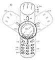
- FIG. 1is a perspective view of a radiotelephone in a closed position
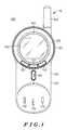
- FIG. 2is a perspective view of the radiotelephone of HG. 1 in an opened position as well as two alternative positions;
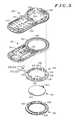
- FIG. 3is an exploded, perspective view of the radiotelephone of FIG. 1 viewed from the bottom down;
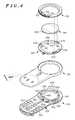
- FIG. 4is an exploded, perspective view of the radiotelephone of FIG. 1 viewed from the top down;
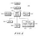
- FIG. 5is a block diagram of the internal, electronic components of the radiotelephone of FIG. 1 .
- the present inventionis a wireless communication device including first and second housings.
- the first housingincludes a housing support capable of retaining a display.
- the second housingincludes a circular portion positioned about a portion of the housing support, namely the support rim, and an extending portion extending away from the circular portion.
- the second housing, particularly the circular portionis capable of rotating around the portion of the support rim of the housing support.
- the first and second housingshave a closed position and one or more opened positions. In the closed position, the circular and extending portions of the second housing are adjacent to the first housing. In one or more opened positions, the circular portion is adjacent to the first housing and at least a portion of the extending portion is positioned away from the first housing.
- a collapsible radiotelephone 100 in a closed position 110there is provided a collapsible radiotelephone 100 in a closed position 110 .
- the radiotelephone 100has wireless communication capabilities and, thus, may be used to communicate with wireless infrastructure, such as cellular base stations, regional and local wireless transponders, and wireless local area networks.
- the radiotelephone 100 described hereinis a representation of the type of wireless communication device that may benefit from the present invention.
- the present inventionmay be applied to any type of portable electronic device and is not limited to the following devices: radiotelephones, cordless phones, paging devices, personal digital assistants, portable computers, pen-based or keyboard-based handheld devices, remote control units, an audio player (such as an MP3 player) and the like. Accordingly, any reference herein to the radiotelephone 100 should also be considered to apply equally to other portable electronic devices.
- the radiotelephone 100includes an upper housing 120 having a generally elongated and planar shape.
- the upper housing 120has an upper circular portion 122 at one end and an upper extending portion 124 extending away from the upper circular portion.
- the upper circular portion 122 and the upper extending portion 124are adjacent to a lower housing (shown in FIG. 2 ).
- an external antenna 180may be provided to enhance the wireless communication capabilities of the radiotelephone 100 .
- Components of the radiotelephone 100are positioned near the upper circular portion 122 including an interchangeable cover 130 , a locking piece 140 , and a display 150 .
- the interchangeable cover 130has a ring-like shape that may be attached to, and detached from, the radiotelephone 100 . Since the interchangeable cover 130 may be easily attached and detached by a user without the need of tools, the user may select among interchangeable covers of different colors to decorate the radiotelephone 100 .
- the interchangeable cover 130may include cover selection buttons 132 and/or indicator lights (not shown) to provide additional functionality to the radiotelephone 100 .
- the preferred embodimentprovides three cover selection keys 132 : a left selection key, and right selection key and a menu key therebetween.
- the display 150may be any type of output device that provides a convenient display of text and/or graphics to the user.
- the display 150is a liquid crystal display having a backlighting system to illuminate the display when lighting conditions are insufficient for proper viewing by the user.
- the locking piece 140locks certain components of the radiotelephone 100 together, which is explained below.
- the locking piece 140also functions as a display lens to protect the display 150 from undesirable, foreign matter.
- the extended portion 124 of the upper housing 120may include upper housing selection buttons 160 and speaker apertures 170 . Although many different selection buttons may be provided on the upper housing 120 , only one upper housing selection button 160 is shown in FIG. 1 by way of example. Thus, the upper housing 120 of the present invention may include one or more selection buttons (such as selection buttons 132 and 160 ) for various types of features including, but not limited to, volume control, menu control, call answering, call termination, caller identification, phone book control, voicemail control, e-mail/messaging control, network browsing, power on/off, and the like.
- the speaker apertures 170direct sounds generated by an audio output device (shown in FIG. 5) to the user.
- the preferred embodiment of the radiotelephone 100is shown in an opened position 210 .
- the portions the radiotelephone 100 that become visible in the opened position 210include a lower housing 220 , a keypad 230 and a microphone aperture 240 .
- the lower housing of the preferred embodimenthas a substantially similar profile to the upper housing 120 .
- the lower housingincludes a lower circular portion 222 and a lower extending portion 224 .
- the upper circular portion 122 of the upper housing 120is adjacent to, and positioned above, the lower circular portion of the lower housing 220 .
- the upper extending portion 124is positioned away from the lower housing. For example, as shown in FIG.
- the upper extending portion 124is positioned the opposite the lower extending portion 124 on opposite sides of the upper and lower circular portions 122 & 222 .
- the keypad 230may include any layout of keys that provide convenient operation of the radiotelephone 100 by the user.
- the microphone aperture 240directs sounds received from the user or other local sounds to an audio input device (shown in FIG. 5 ).
- the preferred embodimentincludes a standard layout of alphanumeric and menu control for operation of the radiotelephone 100 .
- the keypad 230includes twelve standard keys 232 (namely, 0 through 9, # and *) as well as three lower housing selection buttons 234 .
- the radiotelephone 100may include a larger grouping of keys, such as a QWERTY keyboard, if a device having a larger form factor or smaller individual keys is desired.
- the keypad 230may also include a cursor or graphical pointing device such as a joystick, touch pad or track ball.
- the lower housing selection buttons 234may be used for various features including, but not limited to, volume control, menu control, call answering, call termination, caller identification, phone book control, voicemail control, e-mail/messaging control, network browsing, power on/off, and the like.
- the position of the upper housing 120is not restricted the opened position 210 and the closed position 110 described above.
- the upper extending portion 124 of the upper housing 120has at least three functional positions about a housing support or bottom support (described below) of the lower housing 220 .
- the preferred embodiment shown in FIG. 2includes four functional positions, namely opened position 210 , closed position 110 , and auxiliary positions 260 & 270 .
- the opened position 210 and the closed position 110may activate functions of the radiotelephone 100 such as answering an incoming call and terminating an existing call.
- Each of the auxiliary positions 260 & 270may also be set to activate a particular function of the radiotelephone 100 .
- auxiliary position 260may operate to illuminate the display 150 (without answering an incoming call, if one exists), and auxiliary position 270 may operate to provide caller identification information about an incoming call that is not provided in the closed position 110 .
- Another function that may be activated by the functional positions of the upper extending portion 124includes changing between different modes of operation for a multimode device.
- the position of the upper extending portion 124may determine whether the wireless communication device operates as a radiotelephone, a pager, a network browser, an e-mail device, a personal digital assistant, or an audio player.
- Still another function that may be activated by the functional positions of the upper extending portion 124includes scrolling through a predetermined selection of data shown on the display 150 .
- the upper extending portion 124may be rotated to conveniently move up and down a list of contacts and/or phone numbers, or a listing of alphanumeric characters (i.e. “A” through “Z”, “a” through “z”, “0” through “9”, and any special characters).
- This featuremay also be used to operate functions that are not necessarily shown on the display 150 , such as volume control.
- the cover selection buttons 132 , upper housing selection button 160 , and lower housing selection buttons 234may operate independently or in cooperation.
- the each of these selection buttons 132 , 160 & 234may activate a different function of the radiotelephone 100 .
- the upper housing selection button 160its function may change depending upon the position of the upper housing 120 relative to the lower housing 220 .
- the upper housing selection button 160 and the middle button 236 of the lower housing selection buttons 234operate cooperatively.
- the upper housing selection button 160is a mechanical lever that physically contacts the surface of the middle button 236 when a user adjusts the upper housing selection button.
- the opened position 210(and the alternative positions 260 & 270 )
- the upper housing selection button 160does not have any function.
- the radiotelephone 100 of the preferred embodimentincludes a top support 310 in addition to the lower housing 220 , the upper housing 120 , the locking piece 140 and the interchangeable cover 130 described above in reference to FIGS. 1 and 2.
- certain sections of the radiotelephone 100such as an inner surface of the upper housing 120 , an outer surface of the lower housing 220 , the display 150 and other components within the upper and lower housings, are not shown in FIG. 3 to more easily view the relationship among the top support 310 , the lower housing, the upper housing, the locking piece 140 and the interchangeable cover 130 .
- the lower housing 220includes the lower circular portion 222 and the lower extending portion 224 (shown in FIG. 2 ).
- the lower circular portion 222includes the housing support or bottom support 250 and the display 150 (shown in FIGS. 1 & 2 ).
- the bottom support 250includes a bottom support rim 324 having a circular shape and a bottom support base 326 to receive and support the display 150 (shown in FIGS. 1 & 2) such as a backlit liquid crystal display.
- the bottom support rim 324defines a bottom support opening 328 to provide a viewing area of the display 150 to the user.
- the housing support or bottom support 250may be an integrated component that is part of the lower housing 220 or a separable component that is positioned within the lower housing.
- the bottom support 250 of the preferred embodimentis an integrated component that is part of an inside wall 320 of the lower housing 220 .
- the bottom support 250is integrated with one part of the lower housing 220 to retain the display 150 in that area of the lower housing.
- the other part of the lower housing 220includes keypad apertures 322 to reveal user-accessible portions of the keypad 230 .
- the top support 310mates with the bottom support 250 and maintains the upper housing 120 between the top and bottom supports.
- the top and bottom supports 310 & 250are made of a rigid material, preferably a metallic material, to form a strong, inflexible coupling between the top and bottom supports.
- the top support 310includes a top support base 312 and a top support rim 314 having a circular shape.
- the top support 310is positioned over the upper housing 120 so that a lower surface of the top support base 312 is adjacent to an upper surface of the upper circular portion 122 .
- the bottom support 250is positioned under the upper housing 120 so that an upper surface of the bottom support base 326 is adjacent to a lower surface of the upper circular portion 122 .
- the top support rim 314is positioned around the bottom support rim 324 so that an inner surface of the top support rim is adjacent to an outer surface of the bottom support rim.
- the upper housing 120is situated between the top support 310 and the bottom support 250 so that the inner surface of the upper circular portion 122 is adjacent to the outer surface of the top support rim 314 . Accordingly, the upper circular portion 122 is capable of rotating about the top support rim 314 and the bottom support rim 324 .
- the top support rim 314 of the top support 310defines a top support opening 316 to permit the user to see a viewing area of the display 150 .
- the shape of the top support 310may vary, but the top support rim 314 is preferably circular to provide a rotatable surface for the upper housing 120 .
- the top support opening 316 of the top support 310preferably has a shape that does not obstruct the user's view of the display 150 .
- the upper housing 120includes an upper housing opening 340 to permit the user to see a viewing area of the display 150 and, preferably, does not obstruct the user's view of the display.
- the locking piece 140is positioned through the top support 310 and coupled to the bottom support 250 to prevent the top support from detaching from the bottom support. A more detailed explanation is provided below in reference to FIG. 4 .
- the locking piece 140 of the preferred embodimentalso serves as the display lens to protect the display 150 from undesirable, foreign matter
- the upper housing 120may also include a detent assembly 330 to position the upper housing at various positions about the top and bottom supports 310 & 250 . More specifically, the detent assembly 330 permits the upper extending portion 124 of the upper housing 120 to be positioned at various positions about the top support rim 314 and the bottom support rim 324 .
- the detent assembly 330includes a spring 332 and a follower 334 that are supported by the upper circular portion 122 .
- the follower 334is positioned in an aperture 336 through a sidewall of the upper circular portion 122 so that it protrudes passed the inner surface of the upper circular portion.
- the spring 332flexibly supports the follower 334 at this position, so that the follower may mate with a slot 318 provided on the outer surface of the top support rim 314 .
- the detent assembly 330may include a one-piece spring having a projecting form that provides the functions of the spring 332 and the follower 334 of the preferred embodiment.
- the top support 310may have a plurality of slots 318 and, likewise, the upper housing 120 may have a plurality of detent assemblies 330 .
- This structurepermits the radiotelephone 100 , particularly, the upper extending portion 124 of the upper housing 120 , to have at least three positions about the bottom support rim 324 of the lower housing 220 , as explained above in reference to FIG. 2 .
- top support 310is dropped onto the bottom support 250 .
- the top support 310includes one or more top support inner and outer anchors 410 & 412 (also shown in FIG. 3 ), and the bottom support 320 includes corresponding bottom support inner and outer grooves 420 & 422 .
- Top support inner anchors 410 of the top support 310are aligned with corresponding bottom support inner grooves 420 of the bottom support 250 and, similarly, top support outer anchors 412 of the top support are aligned with corresponding bottom support outer grooves 422 of the bottom support.
- the top support 310is rotated, as shown by direction 430 , to lock the top support inner and outer anchors 410 & 412 into the bottom support inner & outer grooves 420 & 422 .
- the locking piece 140is dropped down to prevent the top support 310 from rotating back in a direction opposite the original direction 430 .
- the locking piece 140includes one or more locking piece feet 450 (also shown in FIG. 3) for mating with corresponding bottom support retaining areas 460 of the bottom support 250 .
- the interchangeable cover 130may be attached to, and detached from, the radiotelephone 100 by a user without the need for tools.
- the interchangeable cover 130would have a ring-like shape that may enhance but, preferably, does not obstruct the user's view of the display 150 .
- the interchangeable cover 130includes cover anchors 490 that mate with corresponding top support grooves 470 of the top support 310 .
- the top support 310also includes projections 480 to provide tension against the inner surface of the interchangeable cover 130 in order to retain the cover anchors 490 in the top support grooves 470 .
- the cover selection buttons 132 of the preferred embodimenthas electrical contacts that couple to corresponding electrical contacts of the top support 310 . These corresponding electrical contacts of the top support 310 are coupled to electronic components, discussed below in reference to FIG. 5, supported in the lower housing 250 by a flex cable.
- the electronic components 500 of the radiotelephone 100are housed within the upper and lower housings 120 & 220 .
- the electronic components 500include a processor 510 , a transceiver 520 and an antenna 530 .
- the antenna 530transmits radio frequency (“RF”) signals received from the transceiver 520 and provides RF signals to the transceiver that it receives.
- the transceiver 520converts controls signals received from the processor 510 for transmission by the antenna 530 , and converts RF signal received by the antenna for processing by the processor.
- the processor 510acts as a central processing unit for the radiotelephone 100 and coordinates the operations of the electronic components 500 .
- the processor 510also includes a memory portion 512 to store and retrieve data as well as perform various operations of the radiotelephone 100 .
- a memory portion 512to store and retrieve data as well as perform various operations of the radiotelephone 100 .
- various functions described herein for the electronic components 500may be integrated or segregated and, thus, the present invention is not limited to particular discrete components shown in FIG. 5 .
- the processor 510 and the transceiver 520may be combined in a single integrated circuit, or the processor and the memory portion 512 may be separated to different components.
- the electronic components 500may also include an audio input 540 , an audio output 550 , a display 560 and input keys 570 .
- the audio input 540is a microphone that receives sounds through the microphone aperture 240 (shown in FIG. 2) and the audio output 550 is an earpiece that emits sounds through the speaker apertures 170 (shown in FIGS. 1 & 2 ).
- the display 560is a backlit, liquid crystal display that is shown in FIGS. 1 & 2 as display 150 .
- the input keys 570include internal keys 572 such as the keypad 230 (shown in FIG. 2) and external keys 574 such as the upper housing selection button 160 and the cover selection buttons 132 (shown in FIGS. 1 & 2 ).
- the display 560 and the input keys 570may also include connections to any indicator lights or selection buttons provided on the interchangeable cover 140 , as described above.
- the electronic components 500 of the present inventionfurther include at least one position sensor 580 .
- the position sensor 580 of the preferred embodimentis a Hall effect detector that includes a magnet mounted on the upper circular portion 122 of the upper housing 120 and a Hall effect switch mounted to the lower circular portion 222 of the lower housing 220 .
- a single position sensor 580is capable of detecting a particular position of the upper housing 120 relative to the lower housing 220 .
- a plurality of position sensors 580may be positioned throughout the circular portions 122 & 222 of the upper and lower housings 120 & 220 to detect various positions of the upper housing relative to the lower housing, such as the closed position 110 , an opened position 210 , and additional positions (such as 260 & 270 ) about the housing support 250 .
- the position sensor 580is capable of determining a particular position of the upper housing 120 relative to the lower housing 220 and generating a response signal corresponding to the particular position.
- the processor 510is then effective to activate a particular function of the radiotelephone 100 in response to the response signal when the upper housing 120 is positioned at one of the additional positions.
Landscapes
- Engineering & Computer Science (AREA)
- Signal Processing (AREA)
- Human Computer Interaction (AREA)
- Computer Networks & Wireless Communication (AREA)
- Telephone Set Structure (AREA)
Abstract
Description
Claims (25)
Priority Applications (9)
| Application Number | Priority Date | Filing Date | Title |
|---|---|---|---|
| US09/826,180US6768899B2 (en) | 2001-04-04 | 2001-04-04 | Rotational mechanism for a wireless communication device |
| AU2002307040AAU2002307040A1 (en) | 2001-04-04 | 2002-03-29 | Rotational mechanism for a wireless communication device |
| CNB02807856XACN1307806C (en) | 2001-04-04 | 2002-03-29 | Rotational mechanism for wireless communication device |
| PCT/US2002/010179WO2002082783A2 (en) | 2001-04-04 | 2002-03-29 | Rotational mechanism for a wireless communication device |
| MXPA03009076AMXPA03009076A (en) | 2001-04-04 | 2002-03-29 | Rotational mechanism for a wireless communication device. |
| EP02763887AEP1386407A4 (en) | 2001-04-04 | 2002-03-29 | Rotational mechanism for a wireless communication device |
| US10/299,352US6766182B2 (en) | 2001-04-04 | 2002-11-19 | Rotational mechanism for a wireless communication device |
| US10/855,137US20050070343A1 (en) | 2001-04-04 | 2004-05-27 | Rotational mechanism for a wireless communication device |
| US11/225,610US20060035685A1 (en) | 2001-04-04 | 2005-09-13 | Interchangeable cover for a rotational mechanism of a wireless communication device |
Applications Claiming Priority (1)
| Application Number | Priority Date | Filing Date | Title |
|---|---|---|---|
| US09/826,180US6768899B2 (en) | 2001-04-04 | 2001-04-04 | Rotational mechanism for a wireless communication device |
Related Child Applications (3)
| Application Number | Title | Priority Date | Filing Date |
|---|---|---|---|
| US10/299,352ContinuationUS6766182B2 (en) | 2001-04-04 | 2002-11-19 | Rotational mechanism for a wireless communication device |
| US10/855,137ContinuationUS20050070343A1 (en) | 2001-04-04 | 2004-05-27 | Rotational mechanism for a wireless communication device |
| US11/225,610ContinuationUS20060035685A1 (en) | 2001-04-04 | 2005-09-13 | Interchangeable cover for a rotational mechanism of a wireless communication device |
Publications (2)
| Publication Number | Publication Date |
|---|---|
| US20030017810A1 US20030017810A1 (en) | 2003-01-23 |
| US6768899B2true US6768899B2 (en) | 2004-07-27 |
Family
ID=25245911
Family Applications (4)
| Application Number | Title | Priority Date | Filing Date |
|---|---|---|---|
| US09/826,180Expired - LifetimeUS6768899B2 (en) | 2001-04-04 | 2001-04-04 | Rotational mechanism for a wireless communication device |
| US10/299,352Expired - LifetimeUS6766182B2 (en) | 2001-04-04 | 2002-11-19 | Rotational mechanism for a wireless communication device |
| US10/855,137AbandonedUS20050070343A1 (en) | 2001-04-04 | 2004-05-27 | Rotational mechanism for a wireless communication device |
| US11/225,610AbandonedUS20060035685A1 (en) | 2001-04-04 | 2005-09-13 | Interchangeable cover for a rotational mechanism of a wireless communication device |
Family Applications After (3)
| Application Number | Title | Priority Date | Filing Date |
|---|---|---|---|
| US10/299,352Expired - LifetimeUS6766182B2 (en) | 2001-04-04 | 2002-11-19 | Rotational mechanism for a wireless communication device |
| US10/855,137AbandonedUS20050070343A1 (en) | 2001-04-04 | 2004-05-27 | Rotational mechanism for a wireless communication device |
| US11/225,610AbandonedUS20060035685A1 (en) | 2001-04-04 | 2005-09-13 | Interchangeable cover for a rotational mechanism of a wireless communication device |
Country Status (6)
| Country | Link |
|---|---|
| US (4) | US6768899B2 (en) |
| EP (1) | EP1386407A4 (en) |
| CN (1) | CN1307806C (en) |
| AU (1) | AU2002307040A1 (en) |
| MX (1) | MXPA03009076A (en) |
| WO (1) | WO2002082783A2 (en) |
Cited By (17)
| Publication number | Priority date | Publication date | Assignee | Title |
|---|---|---|---|---|
| US20030104791A1 (en)* | 2001-05-17 | 2003-06-05 | Engstrom G. Eric | Adding peripherals to mobile device via smart interchangeable cover |
| US20030105961A1 (en)* | 2001-11-30 | 2003-06-05 | Peter Zatloukal | Avoiding attachment of an ineligible smart interchangeable cover to an electronic device |
| US20030104789A1 (en)* | 2001-12-04 | 2003-06-05 | Tonya Torri | User interface for a handheld wireless communication device |
| US20040018862A1 (en)* | 2002-07-22 | 2004-01-29 | Jon Godston | Self operating opening mechanism for use in a hand-held electronic device |
| US20040127267A1 (en)* | 2002-12-30 | 2004-07-01 | Daniel Wong | Rotating user interface |
| US20040184002A1 (en)* | 2002-08-21 | 2004-09-23 | Kamran Siminou | Intelligent patient interface for ophthalmic instruments |
| US20040203493A1 (en)* | 2002-09-27 | 2004-10-14 | Christopher Carlson | Illuminated interchangeable bezel assembly for a cellular telephone |
| US20040229662A1 (en)* | 2003-05-12 | 2004-11-18 | Siemens Information | Mobile communication device having extendable display |
| US20040253989A1 (en)* | 2003-06-12 | 2004-12-16 | Tupler Amy M. | Radio communication device having a navigational wheel |
| US20050009556A1 (en)* | 2003-07-07 | 2005-01-13 | Hickey Kurt M. | Mobile computing devices having rotationally exposed user interface devices |
| US20050070343A1 (en)* | 2001-04-04 | 2005-03-31 | Janninck Mark Daniel | Rotational mechanism for a wireless communication device |
| US20060019725A1 (en)* | 2004-07-20 | 2006-01-26 | Inventec Appliances Corporation | Personal handphone system handset for children |
| US20060146013A1 (en)* | 2005-01-04 | 2006-07-06 | Arneson Theodore R | Electronic device with virtual image display |
| KR100685218B1 (en) | 2005-08-30 | 2007-02-22 | 삼성전자주식회사 | Rotation and click type portable terminal and data input method using the same |
| USD550712S1 (en)* | 2006-02-10 | 2007-09-11 | Samsung Electronics Co., Ltd. | MP3 player |
| USD552126S1 (en)* | 2006-06-20 | 2007-10-02 | Marcus Lewis | Communications device |
| US20090273888A1 (en)* | 2005-09-20 | 2009-11-05 | Sugatsune Kogyo Co., Ltd. | Mobile device |
Families Citing this family (98)
| Publication number | Priority date | Publication date | Assignee | Title |
|---|---|---|---|---|
| US6131047A (en) | 1997-12-30 | 2000-10-10 | Ericsson Inc. | Radiotelephones having contact-sensitive user interfaces and methods of operating same |
| US6414290B1 (en)* | 1998-03-19 | 2002-07-02 | Graphic Packaging Corporation | Patterned microwave susceptor |
| US7150526B2 (en) | 2000-06-02 | 2006-12-19 | Oakley, Inc. | Wireless interactive headset |
| US8482488B2 (en) | 2004-12-22 | 2013-07-09 | Oakley, Inc. | Data input management system for wearable electronically enabled interface |
| US20120105740A1 (en) | 2000-06-02 | 2012-05-03 | Oakley, Inc. | Eyewear with detachable adjustable electronics module |
| US7461936B2 (en) | 2000-06-02 | 2008-12-09 | Oakley, Inc. | Eyeglasses with detachable adjustable electronics module |
| DE10107702A1 (en)* | 2001-02-19 | 2002-08-29 | Siemens Ag | Miniaturized telecommunication device |
| US7039033B2 (en)* | 2001-05-07 | 2006-05-02 | Ixi Mobile (Israel) Ltd. | System, device and computer readable medium for providing a managed wireless network using short-range radio signals |
| US7013009B2 (en) | 2001-06-21 | 2006-03-14 | Oakley, Inc. | Eyeglasses with wireless communication features |
| US6970696B1 (en)* | 2001-07-03 | 2005-11-29 | At&T Corp. | Method and apparatus for controlling a network device |
| CN1177453C (en)* | 2001-07-19 | 2004-11-24 | 朱占新 | Mobile phone set with rotatable display screen |
| US20050030917A1 (en)* | 2001-08-17 | 2005-02-10 | Amit Haller | Device, system, method and computer readable medium obtaining a network attribute, such as a DNS address, for a short distance wireless network |
| US20040125762A1 (en)* | 2001-08-17 | 2004-07-01 | Amit Haller | Device, system, method and computer readable medium for attaching to a device identifited by an access point name in a wide area network providing particular services |
| US7016334B2 (en)* | 2001-08-17 | 2006-03-21 | Ixi Mobile ( Israel) Ltd. | Device, system, method and computer readable medium for fast recovery of IP address change |
| US7295532B2 (en)* | 2001-08-17 | 2007-11-13 | Ixi Mobile (R & D), Ltd. | System, device and computer readable medium for providing networking services on a mobile device |
| US20040081129A1 (en)* | 2001-08-17 | 2004-04-29 | Amit Haller | Device, system, method and computer readable medium for selectively attaching to a cellular data service |
| JP2003174495A (en)* | 2001-09-28 | 2003-06-20 | Nec Corp | Folding portable information terminal |
| US6957045B2 (en)* | 2001-10-26 | 2005-10-18 | Ixi Mobile (Israel) Ltd. | Device, system, computer readable medium and method for providing status information of devices in a short distance wireless network |
| US6845097B2 (en) | 2001-11-21 | 2005-01-18 | Ixi Mobile (Israel) Ltd. | Device, system, method and computer readable medium for pairing of devices in a short distance wireless network |
| US7016648B2 (en)* | 2001-12-18 | 2006-03-21 | Ixi Mobile (Israel) Ltd. | Method, system and computer readable medium for downloading a software component to a device in a short distance wireless network |
| US7013112B2 (en)* | 2001-12-18 | 2006-03-14 | Ixi Mobile (Israel) Ltd. | Method, system and computer readable medium for making a business decision in response to information from a short distance wireless network |
| CA2417581C (en)* | 2002-01-28 | 2008-04-01 | Research In Motion Limited | Multiple-processor wireless mobile communication device |
| US20030153280A1 (en)* | 2002-02-08 | 2003-08-14 | Joe Kopp | Handset having a retractable keypad |
| AU2003217586A1 (en)* | 2002-02-21 | 2003-09-09 | Mobicom Corporation | Article comprising an adaptable input device abstract |
| JP4019750B2 (en)* | 2002-03-06 | 2007-12-12 | 日本電気株式会社 | Foldable portable information terminal, response hold method used therefor, and program thereof |
| JP2003298698A (en)* | 2002-03-29 | 2003-10-17 | Nec Corp | Folding portable information terminal |
| US8001488B1 (en)* | 2002-05-31 | 2011-08-16 | Hewlett-Packard Development Company, L.P. | User interface dial with display |
| CN1720763B (en) | 2002-07-26 | 2013-06-12 | 奥克利有限公司 | Glasses |
| US6968508B2 (en)* | 2002-07-30 | 2005-11-22 | Motorola, Inc. | Rotating user interface |
| US6909878B2 (en)* | 2002-08-20 | 2005-06-21 | Ixi Mobile (Israel) Ltd. | Method, system and computer readable medium for providing an output signal having a theme to a device in a short distance wireless network |
| US20040056651A1 (en)* | 2002-09-19 | 2004-03-25 | Daniele Marietta Bersana | System for detecting a flip-lid position of a personal electronic device |
| JP3999092B2 (en)* | 2002-09-30 | 2007-10-31 | 京セラ株式会社 | Stackable mobile terminal device |
| US7356571B2 (en)* | 2002-10-07 | 2008-04-08 | Ixi Mobile (R&D), Ltd. | System, method and processor readable medium for downloading information within a predetermined period of time to a device in a network responsive to price selection |
| KR100810300B1 (en)* | 2002-10-15 | 2008-03-06 | 삼성전자주식회사 | Portable communication device |
| US7551945B2 (en) | 2002-11-20 | 2009-06-23 | Panasonic Corporation | Mobile communication terminal |
| US7023421B2 (en)* | 2002-11-26 | 2006-04-04 | Motorola, Inc. | Subscriber device with adaptable user interface and method thereof |
| CN1510883A (en)* | 2002-12-24 | 2004-07-07 | 北京嘉盛联侨信息工程技术有限公司 | Pivoted mobile telephone and controlling method thereof |
| CN1510884A (en)* | 2002-12-24 | 2004-07-07 | ������ʢ������Ϣ���̼�������˾ | Pivot axis of digital mobile communication facilities and installation thereof |
| US6856792B2 (en) | 2002-12-30 | 2005-02-15 | Motorola, Inc. | Self operating opening mechanism for use in a hand-held electronic device |
| US7142667B2 (en) | 2002-12-30 | 2006-11-28 | Motorola, Inc. | Self operating opening mechanism for use in hand-held electronic device |
| JP4402355B2 (en)* | 2003-01-21 | 2010-01-20 | 京セラ株式会社 | Stackable mobile terminal device |
| US7167680B2 (en)* | 2003-02-05 | 2007-01-23 | Ixi Mobile (Israel) Ltd. | Method, system and computer readable medium for adjusting output signals for a plurality of devices in a short distance wireless network responsive to a selected environment |
| US20040185922A1 (en)* | 2003-02-06 | 2004-09-23 | Thomas Sutton | Smartphone with novel opening mechanism |
| US7043284B2 (en)* | 2003-02-06 | 2006-05-09 | Flextronics Ap, Llc | Integrated cellular phone, digital camera, and PDA, with swivel mechanism providing access to the interface elements of each function |
| US7054146B2 (en)* | 2003-02-19 | 2006-05-30 | Flextroncis Ap, Llc | Method for manufacturing and kit for assembling a personal entertainment device (PED) with double-opening flap |
| US6914774B1 (en)* | 2003-02-27 | 2005-07-05 | Palmone, Inc. | Transparent cover with access to multi-way navigation assembly |
| US7308733B2 (en)* | 2003-05-15 | 2007-12-18 | Lg Electronics Inc. | Swivel hinge assembly and electronic device having the same |
| US20040242288A1 (en)* | 2003-05-29 | 2004-12-02 | Henrik Balle | Portable communication apparatus, a rotary input device having an end-user-exchangeable element, and an end-user-exchangeable element for a rotary input device |
| US20040259585A1 (en)* | 2003-06-04 | 2004-12-23 | Avi Yitzchak | Wireless device having dual bus archeticure for interfacing with cellular signals and short-range radio signals |
| US7366901B2 (en)* | 2003-08-01 | 2008-04-29 | Ixi Mobile (R&D), Ltd. | Device, system, method and computer readable medium for identifying and authenticating a cellular device using a short-range radio address |
| JP2005078316A (en)* | 2003-08-29 | 2005-03-24 | Kyocera Corp | Mobile terminal device |
| US7003104B2 (en)* | 2003-10-13 | 2006-02-21 | Hanbit Precision Co., Ltd. | Apparatus for opening and closing cover of cellular phone |
| KR100566276B1 (en)* | 2003-10-17 | 2006-03-30 | 삼성전자주식회사 | Handheld terminal and its swing hinge module |
| US7162030B2 (en)* | 2003-12-23 | 2007-01-09 | Nokia Corporation | Communication device with rotating housing |
| JP4975240B2 (en)* | 2004-03-26 | 2012-07-11 | カシオ計算機株式会社 | Terminal device and program |
| US20060031339A1 (en)* | 2004-08-09 | 2006-02-09 | International Business Machines Corporation | Integration of instant messaging clients with user devices |
| WO2006035260A1 (en)* | 2004-09-30 | 2006-04-06 | Nokia Corporation | Assignment of functions to a softkey |
| US20060145947A1 (en)* | 2005-01-04 | 2006-07-06 | Arneson Theodore R | Foldable electronic device with virtual image display |
| US7187952B2 (en)* | 2005-03-07 | 2007-03-06 | Benq Corporation | Method of accepting a phone call based on motion properties of the phone and related device |
| US20060227102A1 (en)* | 2005-04-12 | 2006-10-12 | Andrea Finke-Anlauff | Multi-function electronic device |
| TWI274982B (en)* | 2005-05-06 | 2007-03-01 | Asia Optical Co Inc | Handheld input device having a rotating mechanism |
| EP1886533A1 (en)* | 2005-06-03 | 2008-02-13 | Nokia Corporation | Headset with adjustable boom |
| US8331603B2 (en)* | 2005-06-03 | 2012-12-11 | Nokia Corporation | Headset |
| US7983723B2 (en) | 2005-06-15 | 2011-07-19 | Sony Ericsson Mobile Communications Ab | Closed mode user interface for wireless communication devices |
| US20070004451A1 (en)* | 2005-06-30 | 2007-01-04 | C Anderson Eric | Controlling functions of a handheld multifunction device |
| US7194154B2 (en)* | 2005-08-15 | 2007-03-20 | Sony Ericsson Mobile Communications Ab | Optical connector |
| KR100678135B1 (en)* | 2005-09-06 | 2007-02-02 | 삼성전자주식회사 | Handheld terminal |
| KR100810763B1 (en) | 2005-09-07 | 2008-03-07 | (주)케이티에프테크놀로지스 | Sliding Terminal |
| JP5001624B2 (en)* | 2005-10-26 | 2012-08-15 | エルジー エレクトロニクス インコーポレイティド | Communication terminal |
| KR100663445B1 (en)* | 2005-11-30 | 2007-01-02 | 삼성전자주식회사 | Hinge device of a portable terminal |
| USD546807S1 (en)* | 2006-05-09 | 2007-07-17 | Samsung Electronics Co., Ltd. | Mobile phone |
| EP2044507B8 (en)* | 2006-07-10 | 2013-07-24 | Ziba Labs LLC | Configurable modular multi-function communication device |
| US7874722B2 (en)* | 2006-08-27 | 2011-01-25 | Nike, Inc. | Watch casing integrally formed with watch band |
| US8511890B2 (en)* | 2006-08-27 | 2013-08-20 | Nike, Inc. | Rocking bezel control |
| EP2095178B1 (en) | 2006-12-14 | 2015-08-12 | Oakley, Inc. | Wearable high resolution audio visual interface |
| JP5496111B2 (en) | 2008-01-10 | 2014-05-21 | アライア エンタープライジーズ,インコーポレーテッド | Customizable modular multifunction communication device |
| US20090225026A1 (en)* | 2008-03-06 | 2009-09-10 | Yaron Sheba | Electronic device for selecting an application based on sensed orientation and methods for use therewith |
| USD600228S1 (en)* | 2008-09-11 | 2009-09-15 | Motorola Inc | Communication device |
| USD609670S1 (en)* | 2008-09-11 | 2010-02-09 | Motorola, Inc. | Communication device |
| US20100151902A1 (en)* | 2008-12-15 | 2010-06-17 | Nokia Corporation | Method and Apparatus for Rotating a First and/or Second Portion of an Electronic Device |
| US20100216513A1 (en)* | 2009-02-23 | 2010-08-26 | Research In Motion Limited | Handheld electronic device with rotatable member |
| US8630089B2 (en) | 2011-01-21 | 2014-01-14 | Blackberry Limited | Resilient swivel coupling mechanism |
| US8498102B2 (en) | 2011-03-04 | 2013-07-30 | Research In Motion Limited | Rotatable coupling mechanism |
| US9053478B2 (en) | 2011-05-03 | 2015-06-09 | Verifone, Inc. | Mobile commerce system |
| US20130062437A1 (en) | 2011-09-06 | 2013-03-14 | Kenneth Scott Hanna | Shower and speaker assembly |
| US10003873B2 (en) | 2011-09-06 | 2018-06-19 | Kohler Co. | Speaker and shower |
| US10945059B2 (en) | 2011-09-06 | 2021-03-09 | Kohler Co. | Shower assembly |
| US9818095B2 (en)* | 2011-10-14 | 2017-11-14 | Verifone, Inc. | Taxi payment system |
| CN204331191U (en) | 2012-02-17 | 2015-05-13 | 奥克利有限公司 | Glasses and dual attachment members |
| USD678468S1 (en) | 2012-04-23 | 2013-03-19 | Kohler Co. | Shower and speaker assembly |
| EP2973533A4 (en) | 2013-03-15 | 2016-11-30 | Oakley Inc | ELECTRONIC ORNAMENTATION FOR EYEWEAR |
| CN205691887U (en) | 2013-06-12 | 2016-11-16 | 奥克利有限公司 | Modular communication system and glasses communication system |
| EP2898956B1 (en)* | 2014-01-27 | 2019-06-12 | Kohler Co. | Speaker and shower |
| CN105137819B (en)* | 2015-07-28 | 2019-07-02 | Oppo广东移动通信有限公司 | A method for playing music and a smart watch |
| CN105006223B (en)* | 2015-07-28 | 2017-07-25 | 广东欧珀移动通信有限公司 | A method for adjusting screen brightness and smart watch |
| CN105137746B (en)* | 2015-07-28 | 2018-03-27 | 广东欧珀移动通信有限公司 | A kind of receives frequency adjusting method and intelligent watch |
| US11157058B2 (en)* | 2019-05-29 | 2021-10-26 | Motorola Mobility Llc | Setting polling interval of open/closed position sensor for a movable portion of an electronic device based on activity state of the electronic device |
| US11360515B1 (en)* | 2021-03-19 | 2022-06-14 | Jon Jay Goeders | Personal hand-held electronic device |
Citations (7)
| Publication number | Priority date | Publication date | Assignee | Title |
|---|---|---|---|---|
| US4484029A (en) | 1983-08-29 | 1984-11-20 | Kenney David S | Cordless telephone switch and line selector |
| DE3323858A1 (en)* | 1983-07-01 | 1985-01-03 | Erwin Brandenstein | Cordless telephone device |
| US5485517A (en) | 1993-12-07 | 1996-01-16 | Gray; Robert R. | Portable wireless telephone having swivel chassis |
| US5504812A (en) | 1994-10-11 | 1996-04-02 | Motorola, Inc. | Headset for use with a radiotelephone |
| GB2315709A (en) | 1996-07-31 | 1998-02-11 | Motorola Inc | Watch radio telephone having number entry keys spaced around a perimeter of theanalogue watch face |
| US6016347A (en) | 1998-03-04 | 2000-01-18 | Hello Direct, Inc. | Optical switch for headset |
| US6230028B1 (en)* | 1999-01-29 | 2001-05-08 | Sony Coporation | Simplification of portable radio telephone's operation |
Family Cites Families (30)
| Publication number | Priority date | Publication date | Assignee | Title |
|---|---|---|---|---|
| US3889190A (en)* | 1974-06-18 | 1975-06-10 | Charles Palmer | Communications transceiver adapted for mounting on a helmet |
| US4882745A (en)* | 1987-05-08 | 1989-11-21 | Silver Alan H | Cordless headset telephone |
| JPH06252824A (en)* | 1993-02-26 | 1994-09-09 | Sanyo Electric Co Ltd | Portable handset |
| JPH08223260A (en)* | 1995-02-16 | 1996-08-30 | Fujitsu Ltd | Mobile wireless terminal |
| JPH08340565A (en)* | 1995-06-13 | 1996-12-24 | Nec Shizuoka Ltd | Selective call radio receiver with protection cover |
| US5706255A (en)* | 1995-08-24 | 1998-01-06 | Mckay; Christopher B. | Timekeeping and magnifying device |
| US6360104B1 (en)* | 1995-09-21 | 2002-03-19 | International Business Machines Corporation | Personal communicator including a handset phone with an integrated virtual image display |
| US5848152A (en)* | 1995-09-26 | 1998-12-08 | Motorola, Inc. | Communication device having interchangeable faceplates and active keypad cover |
| US6347218B1 (en)* | 1996-02-28 | 2002-02-12 | Nokia Mobile Phones Limited | Electronic device with housing supplement |
| US6009336A (en)* | 1996-07-10 | 1999-12-28 | Motorola, Inc. | Hand-held radiotelephone having a detachable display |
| US6073033A (en)* | 1996-11-01 | 2000-06-06 | Telxon Corporation | Portable telephone with integrated heads-up display and data terminal functions |
| US5768370A (en)* | 1997-01-08 | 1998-06-16 | Nokia Mobile Phones, Ltd. | User changeable cosmetic phone interface |
| JP2944582B2 (en)* | 1997-06-25 | 1999-09-06 | 埼玉日本電気株式会社 | Foldable mobile phone |
| JPH1155724A (en)* | 1997-08-05 | 1999-02-26 | Sanyo Electric Co Ltd | Portable telephone set |
| US6266236B1 (en)* | 1997-08-27 | 2001-07-24 | Vadem | Apparatus and method for connecting and articulating display in a portable computer having multiple display orientations |
| US6141540A (en)* | 1998-06-15 | 2000-10-31 | Motorola, Inc. | Dual mode communication device |
| GB2350523B (en)* | 1999-05-26 | 2003-11-26 | Nokia Mobile Phones Ltd | Communication device |
| WO2001015331A1 (en)* | 1999-08-19 | 2001-03-01 | Bequir Kevin A | Compact portable handheld telephone |
| USD427172S (en)* | 1999-08-19 | 2000-06-27 | Bequir Kevin A | Portable telephone |
| US6522790B1 (en)* | 1999-09-28 | 2003-02-18 | Motorola, Inc. | Method and apparatus for merging images |
| FI108096B (en)* | 1999-12-28 | 2001-11-15 | Nokia Mobile Phones Ltd | Capacitively connected keypad structure |
| JP3509681B2 (en)* | 2000-01-21 | 2004-03-22 | 加藤電機株式会社 | Small switchgear |
| JP2001237932A (en)* | 2000-02-21 | 2001-08-31 | Nec Corp | Portable terminal device and radio communication terminal device |
| US6347281B1 (en)* | 2000-03-08 | 2002-02-12 | R. Mark Litzsinger | Remote global positioning device and method |
| US6549789B1 (en)* | 2000-04-28 | 2003-04-15 | Motorola Inc. | Portable electronic device with an adaptable user interface |
| US6658272B1 (en)* | 2000-04-28 | 2003-12-02 | Motorola, Inc. | Self configuring multiple element portable electronic device |
| US6748242B1 (en)* | 2000-08-04 | 2004-06-08 | Nokia Mobile Phones Ltd. | Personal communication device with full keyboard and gaming feature |
| GB2366669A (en)* | 2000-08-31 | 2002-03-13 | Nokia Mobile Phones Ltd | Connector for liquid crystal display |
| US6850784B2 (en)* | 2001-01-31 | 2005-02-01 | Microsoft Corporation | Modular two-body design for integration of mobile computing device features with a wireless communication device |
| US6768899B2 (en)* | 2001-04-04 | 2004-07-27 | Motorola, Inc. | Rotational mechanism for a wireless communication device |
- 2001
- 2001-04-04USUS09/826,180patent/US6768899B2/ennot_activeExpired - Lifetime
- 2002
- 2002-03-29AUAU2002307040Apatent/AU2002307040A1/ennot_activeAbandoned
- 2002-03-29CNCNB02807856XApatent/CN1307806C/ennot_activeExpired - Lifetime
- 2002-03-29WOPCT/US2002/010179patent/WO2002082783A2/ennot_activeApplication Discontinuation
- 2002-03-29EPEP02763887Apatent/EP1386407A4/ennot_activeCeased
- 2002-03-29MXMXPA03009076Apatent/MXPA03009076A/enactiveIP Right Grant
- 2002-11-19USUS10/299,352patent/US6766182B2/ennot_activeExpired - Lifetime
- 2004
- 2004-05-27USUS10/855,137patent/US20050070343A1/ennot_activeAbandoned
- 2005
- 2005-09-13USUS11/225,610patent/US20060035685A1/ennot_activeAbandoned
Patent Citations (8)
| Publication number | Priority date | Publication date | Assignee | Title |
|---|---|---|---|---|
| DE3323858A1 (en)* | 1983-07-01 | 1985-01-03 | Erwin Brandenstein | Cordless telephone device |
| JPS6021636A (en) | 1983-07-01 | 1985-02-04 | エルヴイン・ブランデンシユタイン | Radio telephone set |
| US4484029A (en) | 1983-08-29 | 1984-11-20 | Kenney David S | Cordless telephone switch and line selector |
| US5485517A (en) | 1993-12-07 | 1996-01-16 | Gray; Robert R. | Portable wireless telephone having swivel chassis |
| US5504812A (en) | 1994-10-11 | 1996-04-02 | Motorola, Inc. | Headset for use with a radiotelephone |
| GB2315709A (en) | 1996-07-31 | 1998-02-11 | Motorola Inc | Watch radio telephone having number entry keys spaced around a perimeter of theanalogue watch face |
| US6016347A (en) | 1998-03-04 | 2000-01-18 | Hello Direct, Inc. | Optical switch for headset |
| US6230028B1 (en)* | 1999-01-29 | 2001-05-08 | Sony Coporation | Simplification of portable radio telephone's operation |
Cited By (31)
| Publication number | Priority date | Publication date | Assignee | Title |
|---|---|---|---|---|
| US20050070343A1 (en)* | 2001-04-04 | 2005-03-31 | Janninck Mark Daniel | Rotational mechanism for a wireless communication device |
| US20030104791A1 (en)* | 2001-05-17 | 2003-06-05 | Engstrom G. Eric | Adding peripherals to mobile device via smart interchangeable cover |
| US20030105961A1 (en)* | 2001-11-30 | 2003-06-05 | Peter Zatloukal | Avoiding attachment of an ineligible smart interchangeable cover to an electronic device |
| US20030104789A1 (en)* | 2001-12-04 | 2003-06-05 | Tonya Torri | User interface for a handheld wireless communication device |
| US7231188B2 (en)* | 2002-07-22 | 2007-06-12 | Motorola, Inc. | Self operating opening mechanism for use in a hand-held electronic device |
| US20040018862A1 (en)* | 2002-07-22 | 2004-01-29 | Jon Godston | Self operating opening mechanism for use in a hand-held electronic device |
| US20040184002A1 (en)* | 2002-08-21 | 2004-09-23 | Kamran Siminou | Intelligent patient interface for ophthalmic instruments |
| US7488074B2 (en) | 2002-08-21 | 2009-02-10 | Neuroptics, Inc. | Intelligent patient interface for ophthalmic instruments |
| US20070206153A1 (en)* | 2002-08-21 | 2007-09-06 | Neuroptics, Inc. A California Corporation | Intelligent patient interface for ophthalmic instruments |
| US7901079B2 (en) | 2002-08-21 | 2011-03-08 | Neuroptics, Inc. | Intelligent patient interface for ophthalmic instruments |
| US7216985B2 (en)* | 2002-08-21 | 2007-05-15 | Neuroptics, Inc. California Corp. | Intelligent patient interface for ophthalmic instruments |
| US20040203493A1 (en)* | 2002-09-27 | 2004-10-14 | Christopher Carlson | Illuminated interchangeable bezel assembly for a cellular telephone |
| US20060148425A1 (en)* | 2002-09-27 | 2006-07-06 | Christopher Carlson | Illuminated interchangeable bezel assembly for a cellular telephone |
| US7050764B2 (en)* | 2002-09-27 | 2006-05-23 | Motorola, Inc. | Illuminated interchangeable bezel assembly for a cellular telephone |
| US7031759B2 (en)* | 2002-12-30 | 2006-04-18 | Motorola, Inc. | Rotating user interface |
| US20060035687A1 (en)* | 2002-12-30 | 2006-02-16 | Daniel Wong | Rotating user interface |
| US20040127267A1 (en)* | 2002-12-30 | 2004-07-01 | Daniel Wong | Rotating user interface |
| US7400915B2 (en) | 2002-12-30 | 2008-07-15 | Motorola Inc | Rotating user interface |
| WO2004062116A3 (en)* | 2002-12-30 | 2004-12-02 | Motorola Inc | Rotating user interface |
| US7149557B2 (en)* | 2003-05-12 | 2006-12-12 | Siemens Communications, Inc. | Mobile communication device having extendable display |
| US20040229662A1 (en)* | 2003-05-12 | 2004-11-18 | Siemens Information | Mobile communication device having extendable display |
| US20040253989A1 (en)* | 2003-06-12 | 2004-12-16 | Tupler Amy M. | Radio communication device having a navigational wheel |
| US20050009556A1 (en)* | 2003-07-07 | 2005-01-13 | Hickey Kurt M. | Mobile computing devices having rotationally exposed user interface devices |
| US7050767B2 (en)* | 2003-07-07 | 2006-05-23 | Sony Ericsson Mobile Communications, Ab | Mobile computing devices having rotationally exposed user interface devices |
| US20060019725A1 (en)* | 2004-07-20 | 2006-01-26 | Inventec Appliances Corporation | Personal handphone system handset for children |
| US20060146013A1 (en)* | 2005-01-04 | 2006-07-06 | Arneson Theodore R | Electronic device with virtual image display |
| KR100685218B1 (en) | 2005-08-30 | 2007-02-22 | 삼성전자주식회사 | Rotation and click type portable terminal and data input method using the same |
| US20090273888A1 (en)* | 2005-09-20 | 2009-11-05 | Sugatsune Kogyo Co., Ltd. | Mobile device |
| US8730658B2 (en)* | 2005-09-20 | 2014-05-20 | Sugatsune Kogyo Co., Ltd. | Portable device |
| USD550712S1 (en)* | 2006-02-10 | 2007-09-11 | Samsung Electronics Co., Ltd. | MP3 player |
| USD552126S1 (en)* | 2006-06-20 | 2007-10-02 | Marcus Lewis | Communications device |
Also Published As
| Publication number | Publication date |
|---|---|
| WO2002082783A2 (en) | 2002-10-17 |
| CN1500312A (en) | 2004-05-26 |
| US20030017810A1 (en) | 2003-01-23 |
| EP1386407A4 (en) | 2007-08-15 |
| MXPA03009076A (en) | 2004-02-17 |
| AU2002307040A1 (en) | 2002-10-21 |
| WO2002082783A3 (en) | 2003-11-20 |
| US20030068988A1 (en) | 2003-04-10 |
| US6766182B2 (en) | 2004-07-20 |
| US20050070343A1 (en) | 2005-03-31 |
| CN1307806C (en) | 2007-03-28 |
| US20060035685A1 (en) | 2006-02-16 |
| EP1386407A2 (en) | 2004-02-04 |
Similar Documents
| Publication | Publication Date | Title |
|---|---|---|
| US6768899B2 (en) | Rotational mechanism for a wireless communication device | |
| US7050764B2 (en) | Illuminated interchangeable bezel assembly for a cellular telephone | |
| US8170633B2 (en) | Mobile terminal configured to be mounted on a user's wrist or forearm | |
| US20090156255A1 (en) | Mobile terminal | |
| US7043284B2 (en) | Integrated cellular phone, digital camera, and PDA, with swivel mechanism providing access to the interface elements of each function | |
| EP1161062B1 (en) | Foldable electronic device | |
| US20030064750A1 (en) | User interfacing device for PDA/wireless terminal | |
| KR20040045850A (en) | User exchangeable mobile phone keypad | |
| WO2003034695A1 (en) | Textual and telephony dual input device | |
| WO2005069588A1 (en) | Apparatus for mobile terminal display | |
| US7729114B2 (en) | Keypad assembly and portable electronic device using the same | |
| US20060007139A1 (en) | Device and method for configuring a user operated screen controller | |
| US20070123320A1 (en) | Key input device for portable terminal | |
| EP1924056B1 (en) | Folding type mobile terminal | |
| CA2767373C (en) | Retention mechanism for a navigation tool | |
| JP3688317B2 (en) | Portable wireless device | |
| JP4574541B2 (en) | Electronics | |
| KR100426268B1 (en) | Mobile communication terminal having extension liquid-crystal display | |
| EP1766752B1 (en) | Integrated cellular phone, digital camera, and pda, with swivel mechanism providing access to the interface elements of each function | |
| EP1349350B1 (en) | Mobile telephone housing with interchangeable bezel | |
| JP4566016B2 (en) | Small electronic equipment | |
| US20080287157A1 (en) | Wireless mobile communications terminals and methods using the same | |
| KR20070066272A (en) | Mobile communication terminal | |
| KR20050044163A (en) | Input device for portable terminal |
Legal Events
| Date | Code | Title | Description |
|---|---|---|---|
| AS | Assignment | Owner name:MOTOROLA, INC.,, ILLINOIS Free format text:ASSIGNMENT OF ASSIGNORS INTEREST;ASSIGNORS:JANNINCK, MARK DANIEL;OLIVER, MARK WILLIAM;REEL/FRAME:011685/0894 Effective date:20010402 | |
| STCF | Information on status: patent grant | Free format text:PATENTED CASE | |
| CC | Certificate of correction | ||
| FPAY | Fee payment | Year of fee payment:4 | |
| AS | Assignment | Owner name:MOTOROLA MOBILITY, INC, ILLINOIS Free format text:ASSIGNMENT OF ASSIGNORS INTEREST;ASSIGNOR:MOTOROLA, INC;REEL/FRAME:025673/0558 Effective date:20100731 | |
| FPAY | Fee payment | Year of fee payment:8 | |
| AS | Assignment | Owner name:MOTOROLA MOBILITY LLC, ILLINOIS Free format text:CHANGE OF NAME;ASSIGNOR:MOTOROLA MOBILITY, INC.;REEL/FRAME:029216/0282 Effective date:20120622 | |
| AS | Assignment | Owner name:GOOGLE TECHNOLOGY HOLDINGS LLC, CALIFORNIA Free format text:ASSIGNMENT OF ASSIGNORS INTEREST;ASSIGNOR:MOTOROLA MOBILITY LLC;REEL/FRAME:034432/0001 Effective date:20141028 | |
| FPAY | Fee payment | Year of fee payment:12 |