US6767076B2 - Printhead assembly capping device - Google Patents
Printhead assembly capping deviceDownload PDFInfo
- Publication number
- US6767076B2 US6767076B2US10/102,699US10269902AUS6767076B2US 6767076 B2US6767076 B2US 6767076B2US 10269902 AUS10269902 AUS 10269902AUS 6767076 B2US6767076 B2US 6767076B2
- Authority
- US
- United States
- Prior art keywords
- printhead
- capping device
- assembly
- printhead assembly
- module
- Prior art date
- Legal status (The legal status is an assumption and is not a legal conclusion. Google has not performed a legal analysis and makes no representation as to the accuracy of the status listed.)
- Expired - Lifetime, expires
Links
- 229910000639Spring steelInorganic materials0.000claimsabstractdescription5
- 230000002441reversible effectEffects0.000claimsdescription3
- 238000007790scrapingMethods0.000claimsdescription3
- 238000000465mouldingMethods0.000abstractdescription22
- 239000002245particleSubstances0.000abstractdescription6
- 238000001035dryingMethods0.000abstractdescription4
- 230000000903blocking effectEffects0.000abstractdescription2
- 239000000428dustSubstances0.000abstractdescription2
- 239000000976inkSubstances0.000description47
- 238000001053micromouldingMethods0.000description33
- 238000001125extrusionMethods0.000description28
- 239000002184metalSubstances0.000description20
- 229910052751metalInorganic materials0.000description20
- YKKYCYQDUUXNLN-UHFFFAOYSA-N2,4-dichloro-1-(2-chlorophenyl)benzeneChemical compoundClC1=CC(Cl)=CC=C1C1=CC=CC=C1ClYKKYCYQDUUXNLN-UHFFFAOYSA-N0.000description12
- ONNCPBRWFSKDMQ-UHFFFAOYSA-N2,3',5-trichlorobiphenylChemical compoundClC1=CC=CC(C=2C(=CC=C(Cl)C=2)Cl)=C1ONNCPBRWFSKDMQ-UHFFFAOYSA-N0.000description11
- 229910001374InvarInorganic materials0.000description10
- 239000000853adhesiveSubstances0.000description9
- 230000001070adhesive effectEffects0.000description9
- 239000010410layerSubstances0.000description8
- 238000007639printingMethods0.000description8
- 239000010408filmSubstances0.000description7
- 238000000034methodMethods0.000description6
- XUIMIQQOPSSXEZ-UHFFFAOYSA-NSiliconChemical compound[Si]XUIMIQQOPSSXEZ-UHFFFAOYSA-N0.000description5
- 230000008569processEffects0.000description5
- PXHVJJICTQNCMI-UHFFFAOYSA-NNickelChemical group[Ni]PXHVJJICTQNCMI-UHFFFAOYSA-N0.000description4
- 229910052710siliconInorganic materials0.000description4
- 239000010703siliconSubstances0.000description4
- 229920000106Liquid crystal polymerPolymers0.000description3
- 239000004977Liquid-crystal polymers (LCPs)Substances0.000description3
- 239000000306componentSubstances0.000description3
- 238000004026adhesive bondingMethods0.000description2
- 230000002950deficientEffects0.000description2
- 239000000834fixativeSubstances0.000description2
- 239000012530fluidSubstances0.000description2
- 239000010931goldSubstances0.000description2
- 229910052737goldInorganic materials0.000description2
- 238000000608laser ablationMethods0.000description2
- 238000011068loading methodMethods0.000description2
- 229910052759nickelInorganic materials0.000description2
- 238000007789sealingMethods0.000description2
- 239000010409thin filmSubstances0.000description2
- 230000032258transportEffects0.000description2
- XLYOFNOQVPJJNP-UHFFFAOYSA-NwaterSubstancesOXLYOFNOQVPJJNP-UHFFFAOYSA-N0.000description2
- 229910000975Carbon steelInorganic materials0.000description1
- RYGMFSIKBFXOCR-UHFFFAOYSA-NCopperChemical compound[Cu]RYGMFSIKBFXOCR-UHFFFAOYSA-N0.000description1
- 229910001030Iron–nickel alloyInorganic materials0.000description1
- 239000004642PolyimideSubstances0.000description1
- 229910000831SteelInorganic materials0.000description1
- 230000009471actionEffects0.000description1
- 239000012790adhesive layerSubstances0.000description1
- 229910045601alloyInorganic materials0.000description1
- 239000000956alloySubstances0.000description1
- 238000003491arrayMethods0.000description1
- 238000005452bendingMethods0.000description1
- 230000008901benefitEffects0.000description1
- 230000015572biosynthetic processEffects0.000description1
- 239000010962carbon steelSubstances0.000description1
- 229910052802copperInorganic materials0.000description1
- 239000010949copperSubstances0.000description1
- 239000008358core componentSubstances0.000description1
- 239000013078crystalSubstances0.000description1
- 238000001914filtrationMethods0.000description1
- 238000013100final testMethods0.000description1
- 230000002209hydrophobic effectEffects0.000description1
- 238000011065in-situ storageMethods0.000description1
- 238000001746injection mouldingMethods0.000description1
- 238000009434installationMethods0.000description1
- 239000000463materialSubstances0.000description1
- 238000002844meltingMethods0.000description1
- 230000008018meltingEffects0.000description1
- 239000000203mixtureSubstances0.000description1
- 230000003287optical effectEffects0.000description1
- 238000004806packaging method and processMethods0.000description1
- 239000004033plasticSubstances0.000description1
- 229920001721polyimidePolymers0.000description1
- 229920000642polymerPolymers0.000description1
- 230000037452primingEffects0.000description1
- 230000001846repelling effectEffects0.000description1
- 239000000565sealantSubstances0.000description1
- 238000005476solderingMethods0.000description1
- 239000010959steelSubstances0.000description1
- 238000003860storageMethods0.000description1
- 239000000126substanceSubstances0.000description1
- 238000012360testing methodMethods0.000description1
- 239000013598vectorSubstances0.000description1
Images


Classifications
- B—PERFORMING OPERATIONS; TRANSPORTING
- B41—PRINTING; LINING MACHINES; TYPEWRITERS; STAMPS
- B41J—TYPEWRITERS; SELECTIVE PRINTING MECHANISMS, i.e. MECHANISMS PRINTING OTHERWISE THAN FROM A FORME; CORRECTION OF TYPOGRAPHICAL ERRORS
- B41J2/00—Typewriters or selective printing mechanisms characterised by the printing or marking process for which they are designed
- B41J2/005—Typewriters or selective printing mechanisms characterised by the printing or marking process for which they are designed characterised by bringing liquid or particles selectively into contact with a printing material
- B41J2/01—Ink jet
- B41J2/135—Nozzles
- B41J2/165—Prevention or detection of nozzle clogging, e.g. cleaning, capping or moistening for nozzles
- B—PERFORMING OPERATIONS; TRANSPORTING
- B41—PRINTING; LINING MACHINES; TYPEWRITERS; STAMPS
- B41J—TYPEWRITERS; SELECTIVE PRINTING MECHANISMS, i.e. MECHANISMS PRINTING OTHERWISE THAN FROM A FORME; CORRECTION OF TYPOGRAPHICAL ERRORS
- B41J2/00—Typewriters or selective printing mechanisms characterised by the printing or marking process for which they are designed
- B41J2/005—Typewriters or selective printing mechanisms characterised by the printing or marking process for which they are designed characterised by bringing liquid or particles selectively into contact with a printing material
- B41J2/01—Ink jet
- B41J2/135—Nozzles
- B41J2/145—Arrangement thereof
- B41J2/155—Arrangement thereof for line printing
- B—PERFORMING OPERATIONS; TRANSPORTING
- B41—PRINTING; LINING MACHINES; TYPEWRITERS; STAMPS
- B41J—TYPEWRITERS; SELECTIVE PRINTING MECHANISMS, i.e. MECHANISMS PRINTING OTHERWISE THAN FROM A FORME; CORRECTION OF TYPOGRAPHICAL ERRORS
- B41J2/00—Typewriters or selective printing mechanisms characterised by the printing or marking process for which they are designed
- B41J2/005—Typewriters or selective printing mechanisms characterised by the printing or marking process for which they are designed characterised by bringing liquid or particles selectively into contact with a printing material
- B41J2/01—Ink jet
- B41J2/135—Nozzles
- B41J2/165—Prevention or detection of nozzle clogging, e.g. cleaning, capping or moistening for nozzles
- B41J2/16505—Caps, spittoons or covers for cleaning or preventing drying out
- B41J2/16507—Caps, spittoons or covers for cleaning or preventing drying out integral with the printhead
- B—PERFORMING OPERATIONS; TRANSPORTING
- B41—PRINTING; LINING MACHINES; TYPEWRITERS; STAMPS
- B41J—TYPEWRITERS; SELECTIVE PRINTING MECHANISMS, i.e. MECHANISMS PRINTING OTHERWISE THAN FROM A FORME; CORRECTION OF TYPOGRAPHICAL ERRORS
- B41J2/00—Typewriters or selective printing mechanisms characterised by the printing or marking process for which they are designed
- B41J2/005—Typewriters or selective printing mechanisms characterised by the printing or marking process for which they are designed characterised by bringing liquid or particles selectively into contact with a printing material
- B41J2/01—Ink jet
- B41J2/135—Nozzles
- B41J2/165—Prevention or detection of nozzle clogging, e.g. cleaning, capping or moistening for nozzles
- B41J2/16505—Caps, spittoons or covers for cleaning or preventing drying out
- B41J2/16508—Caps, spittoons or covers for cleaning or preventing drying out connected with the printer frame
- B—PERFORMING OPERATIONS; TRANSPORTING
- B41—PRINTING; LINING MACHINES; TYPEWRITERS; STAMPS
- B41J—TYPEWRITERS; SELECTIVE PRINTING MECHANISMS, i.e. MECHANISMS PRINTING OTHERWISE THAN FROM A FORME; CORRECTION OF TYPOGRAPHICAL ERRORS
- B41J2/00—Typewriters or selective printing mechanisms characterised by the printing or marking process for which they are designed
- B41J2/005—Typewriters or selective printing mechanisms characterised by the printing or marking process for which they are designed characterised by bringing liquid or particles selectively into contact with a printing material
- B41J2/01—Ink jet
- B41J2/135—Nozzles
- B41J2/165—Prevention or detection of nozzle clogging, e.g. cleaning, capping or moistening for nozzles
- B41J2/16585—Prevention or detection of nozzle clogging, e.g. cleaning, capping or moistening for nozzles for paper-width or non-reciprocating print heads
- B—PERFORMING OPERATIONS; TRANSPORTING
- B41—PRINTING; LINING MACHINES; TYPEWRITERS; STAMPS
- B41J—TYPEWRITERS; SELECTIVE PRINTING MECHANISMS, i.e. MECHANISMS PRINTING OTHERWISE THAN FROM A FORME; CORRECTION OF TYPOGRAPHICAL ERRORS
- B41J2/00—Typewriters or selective printing mechanisms characterised by the printing or marking process for which they are designed
- B41J2/005—Typewriters or selective printing mechanisms characterised by the printing or marking process for which they are designed characterised by bringing liquid or particles selectively into contact with a printing material
- B41J2/01—Ink jet
- B41J2/135—Nozzles
- B41J2/14—Structure thereof only for on-demand ink jet heads
- B41J2002/14419—Manifold
- B—PERFORMING OPERATIONS; TRANSPORTING
- B41—PRINTING; LINING MACHINES; TYPEWRITERS; STAMPS
- B41J—TYPEWRITERS; SELECTIVE PRINTING MECHANISMS, i.e. MECHANISMS PRINTING OTHERWISE THAN FROM A FORME; CORRECTION OF TYPOGRAPHICAL ERRORS
- B41J2/00—Typewriters or selective printing mechanisms characterised by the printing or marking process for which they are designed
- B41J2/005—Typewriters or selective printing mechanisms characterised by the printing or marking process for which they are designed characterised by bringing liquid or particles selectively into contact with a printing material
- B41J2/01—Ink jet
- B41J2/135—Nozzles
- B41J2/14—Structure thereof only for on-demand ink jet heads
- B41J2002/14491—Electrical connection
- B—PERFORMING OPERATIONS; TRANSPORTING
- B41—PRINTING; LINING MACHINES; TYPEWRITERS; STAMPS
- B41J—TYPEWRITERS; SELECTIVE PRINTING MECHANISMS, i.e. MECHANISMS PRINTING OTHERWISE THAN FROM A FORME; CORRECTION OF TYPOGRAPHICAL ERRORS
- B41J2202/00—Embodiments of or processes related to ink-jet or thermal heads
- B41J2202/01—Embodiments of or processes related to ink-jet heads
- B41J2202/19—Assembling head units
- B—PERFORMING OPERATIONS; TRANSPORTING
- B41—PRINTING; LINING MACHINES; TYPEWRITERS; STAMPS
- B41J—TYPEWRITERS; SELECTIVE PRINTING MECHANISMS, i.e. MECHANISMS PRINTING OTHERWISE THAN FROM A FORME; CORRECTION OF TYPOGRAPHICAL ERRORS
- B41J2202/00—Embodiments of or processes related to ink-jet or thermal heads
- B41J2202/01—Embodiments of or processes related to ink-jet heads
- B41J2202/20—Modules
Definitions
- the following inventionrelates to a printhead assembly capping device for a printer.
- the inventionrelates to a capping device for a printhead assembly of an A4 pagewidth drop on demand printer capable of printing up to 1600 dpi photographic quality at up to 160 pages per minute.
- the overall design of a printer in which the capping can be utilizedrevolves around the use of replaceable printhead modules in an array approximately 81 ⁇ 2 inches (21 cm) long.
- An advantage of such a systemis the ability to easily remove and replace any defective modules in a printhead array. This would eliminate having to scrap an entire printhead if only one chip is defective.
- a printhead module in such a printercan be comprised of a “Memjet” chip, being a chip having mounted thereon a vast number of thermo-actuators in micro-mechanics and micro-electromechanical systems (MEMS).
- MEMSmicro-electromechanical systems
- Such actuatorsmight be those as disclosed in U.S. Pat. No. 6,044,646 to the present applicant, however, might be other MEMS print chips.
- eleven “Memjet” tilescan butt together in a metal channel to form a complete 81 ⁇ 2 inch printhead assembly.
- the printheadbeing the environment within which the capping device of the present invention is to be situated, might typically have six ink chambers and be capable of printing four color process (CMYK) as well as infra-red ink and fixative.
- An air pumpwould supply filtered air through a seventh chamber to the printhead, which could be used to keep foreign particles away from its ink nozzles.
- Each printhead modulereceives ink via an elastomeric extrusion that transfers the ink.
- the printhead assemblyis suitable for printing A4 paper without the need for scanning movement of the printhead across the paper width.
- printheadsthemselves are modular, so printhead arrays can be configured to form printheads of arbitrary width.
- a second printhead assemblycan be mounted on the opposite side of a paper feed path to enable double-sided high speed printing.
- Another object of the present inventionis to provide a printhead assembly including a capping device providing an air flow path during operation of the printer and serving to prevent ingress of foreign particles to printhead nozzles during non-operational period of the printer.
- the present inventionprovides a printhead assembly for a drop on demand ink jet printer, comprising:
- a printhead modulehaving a printhead including ink jet nozzles, the module being affixed to the assembly,
- a capping deviceaffixed to the assembly and movable linearly with respect thereto, the capping device at least partially surrounding the printhead module and movable between a capped position whereby the nozzles are capped by the capping device and an uncapped position whereby the nozzles are uncapped.
- a plurality of printhead modulesare situated along a channel, the modules and channel extending substantially across a pagewidth.
- the capping devicepartly surrounds the channel.
- the capping devicehas an onsert molded elastomeric pad which bears onto one or more of the printhead modules.
- each printhead moduleincludes a nozzle guard to protect the nozzles and wherein the elastomeric pad clamps against the nozzle guard in the capped position.
- the elastomeric padincludes air ducts via which air is pumped to the printhead modules when the capping device is in the uncapped position.
- a camshaftbears against the capping device and serves to move the capping device between said capped and uncapped positions.
- the capping deviceincludes a spring to bias the device with respect to the printhead modules against the camshaft.
- the capping deviceis formed of stainless spring steel.
- each printhead moduleincludes a ramp and wherein the capping device includes a boss that rides over the ramp when the capping device is moved between the capped and uncapped positions, the ramp serving to elastically distort the capping device as it is moved between said capped and uncapped positions so as to prevent scraping of the device against the nozzle guard.
- each printhead modulehas alternating air inlets and outlets cooperating with the elastomeric pad so as to be either sealed off or grouped into air inlet/outlet chambers depending on the position of the capping device, the chambers serving to duct air to the printhead when the capping device is uncapped.
- the capping deviceapplies a compressive force to each printhead module and an underside of the channel.
- rotation of the camshaftis reversible.
- the term “ink”is intended to mean any fluid which flows through the printhead to be delivered to print media.
- the fluidmay be one of many different colored inks, infra-red ink, a fixative or the like.
- FIG. 1is a schematic overall view of a printhead
- FIG. 2is a schematic exploded view of the printhead of FIG. 1;
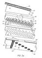
- FIG. 3is a schematic exploded view of an ink jet module
- FIG. 3 ais a schematic exploded inverted illustration of the ink jet module of FIG. 3;
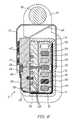
- FIG. 4is a schematic illustration of an assembled ink jet module
- FIG. 5is a schematic inverted illustration of the module of FIG. 4;
- FIG. 6is a schematic close-up illustration of the module of FIG. 4;
- FIG. 7is a schematic illustration of a chip sub-assembly
- FIG. 8 ais a schematic side elevational view of the printhead of FIG. 1;
- FIG. 8 bis a schematic plan view of the printhead of FIG. 1 a;
- FIG. 8 cis a schematic side view (other side) of the printhead of FIG. 8 a;
- FIG. 8 dis a schematic inverted plan view of the printhead of FIG. 8 b;
- FIG. 9is a schematic cross-sectional end elevational view of the printhead of FIG. 1;
- FIG. 10is a schematic illustration of the printhead of FIG. 1 in an uncapped configuration
- FIG. 11is a schematic illustration of the printhead of FIG. 10 in a capped configuration
- FIG. 12 ais a schematic illustration of a capping device
- FIG. 12 bis a schematic illustration of the capping device of FIG. 12 a , viewed from a different angle;
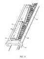
- FIG. 13is a schematic illustration showing the loading of an ink jet module into a printhead
- FIG. 14is a schematic end elevational view of the printhead illustrating the printhead module loading method
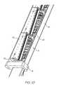
- FIG. 15is a schematic cut-away illustration of the printhead assembly of FIG. 1;
- FIG. 16is a schematic close-up illustration of a portion of the printhead of FIG. 15 showing greater detail in the area of the “Memjet” chip;
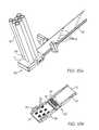
- FIG. 17is a schematic illustration of the end portion of a metal channel and a printhead location molding
- FIG. 18 ais a schematic illustration of an end portion of an elastomeric ink delivery extrusion and a molded end cap
- FIG. 18 bis a schematic illustration of the end cap of FIG. 18 a in an out-folded configuration.
- FIG. 1 of the accompanying drawingsthere is schematically depicted an overall view of a printhead assembly.
- FIG. 2shows the core components of the assembly in an exploded configuration.
- the printhead assembly 10 of the preferred embodimentcomprises eleven printhead modules 11 situated along a metal “Invar” channel 16 .
- At the heart of each printhead module 11is a “Memjet” chip 23 (FIG. 3 ).
- the particular chip chosen in the preferred embodimentbeing a six-color configuration.
- the “Memjet” printhead modules 11are comprised of the “Memjet” chip 23 , a fine pitch flex PCB 26 and two micro-moldings 28 and 34 sandwiching a mid-package film 35 .
- Each module 11forms a sealed unit with independent ink chambers 63 (FIG. 9) which feed the chip 23 .
- the modules 11plug directly onto a flexible elastomeric extrusion 15 which carries air, ink and fixitive.
- the upper surface of the extrusion 15has repeated patterns of holes 21 which align with ink inlets 32 (FIG. 3 a ) on the underside of each module 11 .
- the extrusion 15is bonded onto a flex PCB (flexible printed circuit board).
- the fine pitch flex PCB 26wraps down the side of each printhead module 11 and makes contact with the flex PCB 17 (FIG. 9 ).
- the flex PCB 17carries two busbars 19 (positive) and 20 (negative) for powering each module 11 , as well as all data connections.
- the flex PCB 17is bonded onto the continuous metal “Invar” channel 16 .
- the metal channel 16serves to hold the modules 11 in place and is designed to have a similar coefficient of thermal expansion to that of silicon used in the modules.
- a capping device 12is used to cover the “Memjet” chips 23 when not in use.
- the capping deviceis typically made of spring steel with an onsert molded elastomeric pad 47 (FIG. 12 a ).
- the pad 47serves to duct air into the “Memjet” chip 23 when uncapped and cut off air and cover a nozzle guard 24 (FIG. 9) when capped.
- the capping device 12is actuated by a camshaft 13 that typically rotates throughout 180°.
- the overall thickness of the “Memjet” chipis typically 0.6 mm which includes a 150 micron inlet backing layer 27 and a nozzle guard 24 of 150 micron thickness. These elements are assembled at the wafer scale.
- the nozzle guard 24allows filtered air into an 80 micron cavity 64 (FIG. 16) above the “Memjet” ink nozzles 62 .
- the pressurized airflows through microdroplet holes 45 in the nozzle guard 24 (with the ink during a printing operation) and serves to protect the delicate “Memjet” nozzles 62 by repelling foreign particles.
- a silicon chip backing layer 27ducts ink from the printhead module packaging directly into the rows of “Memjet” nozzles 62 .
- the “Memjet” chip 23is wire bonded 25 from bond pads on the chip at 116 positions to the fine pitch flex PCB 26 .
- the wire bondsare on a 120 micron pitch and are cut as they are bonded onto the fine pitch flex PCB pads (FIG. 3 ).
- the fine pitch flex PCB 26carries data and power from the flex PCB 17 via a series of gold contact pads 69 along the edge of the flex PCB.
- the wire bonding operation between chip and fine pitch flex PCB 26may be done remotely, before transporting, placing and adhering the chip assembly into the printhead module assembly.
- the “Memjet” chips 23can be adhered into the upper micro-molding 28 first and then the fine pitch flex PCB 26 can be adhered into place.
- the wire bonding operationcould then take place in situ, with no danger of distorting the moldings 28 and 34 .
- the upper micro-molding 28can be made of a Liquid Crystal Polymer (LCP) blend. Since the crystal structure of the upper micro-molding 28 is minute, the heat distortion temperature (180° C.-260° C.), the continuous usage temperature (200° C.-240° C.) and soldering heat durability (260° C. for 10 seconds to 310° C. for 10 seconds) are high, regardless of the relatively low melting point.
- LCPLiquid Crystal Polymer
- Each printhead module 11includes an upper micro-molding 28 and a lower micro-molding 34 separated by a mid-package film layer 35 shown in FIG. 3 .
- the mid-package film layer 35can be an inert polymer such as polyimide, which has good chemical resistance and dimensional stability.
- the mid-package film layer 35can have laser ablated holes 65 and can comprise a double-sided adhesive (ie. an adhesive layer on both faces) providing adhesion between the upper micro-molding, the mid-package film layer and the lower micro-molding.
- the upper micro-molding 28has a pair of alignment pins 29 passing through corresponding apertures in the mid-package film layer 35 to be received within corresponding recesses 66 in the lower micro-molding 34 . This serves to align the components when they are bonded together. Once bonded together, the upper and lower micro-moldings form a tortuous ink and air path in the complete “Memjet” printhead module 11 .
- annular ink inlets 32in the underside of the lower micro-molding 34 .
- the air inlet slot 67extends across the lower micro-molding 34 to a secondary inlet which expels air through an exhaust hole 33 , through an aligned hole 68 in fine pitch flex PCB 26 . This serves to repel the print media from the printhead during printing.
- the ink inlets 32continue in the undersurface of the upper micro-molding 28 as does a path from the air inlet slot 67 .
- the ink inletslead to 200 micron exit holes also indicated at 32 in FIG. 3 . These holes correspond to the inlets on the silicon backing layer 27 of the “Memjet” chip 23 .
- elastomeric pads 36on an edge of the lower micro-molding 34 . These serve to take up tolerance and positively located the printhead modules 11 into the metal channel 16 when the modules are micro-placed during assembly.
- a preferred material for the “Memjet” micro-moldingsis a LCP. This has suitable flow characteristics for the fine detail in the moldings and has a relatively low coefficient of thermal expansion.
- Robot picker detailsare included in the upper micro-molding 28 to enable accurate placement of the printhead modules 11 during assembly.
- the upper surface of the upper micro-molding 28 as shown in FIG. 3has a series of alternating air inlets and outlets 31 . These act in conjunction with the capping device 12 and are either sealed off or grouped into air inlet/outlet chambers, depending upon the position of the capping device 12 . They connect air diverted from the inlet slot 67 to the chip 23 depending upon whether the unit is capped or uncapped.
- a capper cam detail 40 including a ramp for the capping deviceis shown at two locations in the upper surface of the upper micro-molding 28 . This facilitates a desirable movement of the capping device 12 to cap or uncap the chip and the air chambers. That is, as the capping device is caused to move laterally across the print chip during a capping or uncapping operation, the ramp of the capper cam detail 40 serves to elastically distort and capping device as it is moved by operation of the camshaft 13 so as to prevent scraping of the device against the nozzle guard 24 .
- the “Memjet” chip assembly 23is picked and bonded into the upper micro-molding 28 on the printhead module 11 .
- the fine pitch flex PCB 26is bonded and wrapped around the side of the assembled printhead module 11 as shown in FIG. 4 .
- the chip 23has more sealant or adhesive 46 applied to its long edges. This serves to “pot” the bond wires 25 (FIG. 6 ), seal the “Memjet” chip 23 to the molding 28 and form a sealed gallery into which filtered air can flow and exhaust through the nozzle guard 24 .
- the flex PCB 17carries all data and power connections from the main PCB (not shown) to each “Memjet” printhead module 11 .
- the flex PCB 17has a series of gold plated, domed contacts 69 (FIG. 2) which interface with contact pads 41 , 42 and 43 on the fine pitch flex PCB 26 of each “Memjet” printhead module 11 .
- Two copper busbar strips 19 and 20are jigged and soldered into place on the flex PCB 17 .
- the busbars 19 and 20connect to a flex termination which also carries data.
- the flex PCB 17is approximately 340 mm in length and is formed from a 14 mm wide strip. It is bonded into the metal channel 16 during assembly and exits from one end of the printhead assembly only.
- the metal U-channel 16 into which the main components are placeis of a special alloy called “Invar 36”. It is a 36% nickel iron alloy possessing a coefficient of thermal expansion of ⁇ fraction (1/10) ⁇ th that of carbon steel at temperatures up to 400° F. The Invar is annealed for optimal dimensional stability.
- the Invaris nickel plated to a 0.056% thickness of the wall section. This helps to further match it to the coefficient of thermal expansion of silicon which is 2 ⁇ 10 ⁇ 6 per °C.
- the Invar channel 16functions to capture the “Memjet” printhead modules 11 in a precise alignment relative to each other and to impart enough force on the modules 11 so as to form a seal between the ink inlets 32 on each printhead module and the outlet holes 21 that are laser ablated into the elastomeric ink delivery extrusion 15 .
- the similar coefficient of thermal expansion of the Invar channel to the silicon chipsallows similar relative movement during temperature changes.
- the elastomeric pads 36 on one side of each printhead module 11serve to “lubricate” them within the channel 16 to take up any further lateral coefficient of thermal expansion tolerances without losing alignment.
- the Invar channelis a cold rolled, annealed and nickel plated strip. Apart from two bends that are required in its formation, the channel has two square cutouts 80 at each end. These mate with snap fittings 81 on the printhead location moldings 14 (FIG. 17 ).
- the elastomeric ink delivery extrusion 15is a non-hydrophobic, precision component. Its function is to transport ink and air to the “Memjet” printhead modules 11 .
- the extrusionis bonded onto the top of the flex PCB 17 during assembly and it has two types of molded end caps. One of these end caps is shown at 70 in FIG. 18 a.
- a series of patterned holes 21are present on the upper surface of the extrusion 15 . These are laser ablated into the upper surface. To this end, a mask is made and placed on the surface of the extrusion, which then has focused laser light applied to it. The holes 21 are evaporated from the upper surface, but the laser does not cut into the lower surface of extrusion 15 due to the focal length of the laser light.
- the molded end cap 70has a spine 73 from which the upper and lower plates are integrally hinged.
- the spine 73includes a row of plugs 74 that are received within the ends of the respective flow passages of the extrusion 15 .
- the other end of the extrusion 15is capped with simple plugs which block the channels in a similar way as the plugs 74 on spine 17 .
- the end cap 70clamps onto the ink extrusion 15 by way of snap engagement tabs 77 . Once assembled with the delivery hoses 78 , ink and air can be received from ink reservoirs and an air pump, possibly with filtration means. The end cap 70 can be connected to either end of the extrusion, ie. at either end of the printhead.
- the plugs 74are pushed into the channels of the extrusion 15 and the plates 71 and 72 are folded over.
- the snap engagement tabs 77clamp the molding and prevent it from slipping off the extrusion.
- the molding 70might interface directly with an ink cartridge.
- a sealing pin arrangementcan also be applied to this molding 70 .
- a perforated, hollow metal pin with an elastomeric collarcan be fitted to the top of the inlet connectors 76 . This would allow the inlets to automatically seal with an ink cartridge when the cartridge is inserted.
- the air inlet and hosemight be smaller than the other inlets in order to avoid accidental charging of the airways with ink.
- the capping device 12 for the “Memjet” printheadwould typically be formed of stainless spring steel.
- An elastomeric seal or onsert molding 47is attached to the capping device as shown in FIGS. 12 a and 12 b .
- the metal part from which the capping device is madeis punched as a blank and then inserted into an injection molding tool ready for the elastomeric onsert to be shot onto its underside.
- Small holes 79(FIG. 12 b ) are present on the upper surface of the metal capping device 12 and can be formed as burst holes. They serve to key the onsert molding 47 to the metal. After the molding 47 is applied, the blank is inserted into a press tool, where additional bending operations and forming of integral springs 48 takes place.
- the elastomeric onsert molding 47has a series of rectangular recesses or air chambers 56 . These create chambers when uncapped.
- the chambers 56are positioned over the air inlet and exhaust holes 30 of the upper micro-molding 28 in the “Memjet” printhead module 11 . These allow the air to flow from one inlet to the next outlet.
- these airways 32are sealed off with a blank section of the onsert molding 47 cutting off airflow to the “Memjet” chip 23 . This prevents the filtered air from drying out and therefore blocking the delicate “Memjet” nozzles.
- Another function of the onsert molding 47is to cover and clamp against the nozzle guard 24 on the “Memjet” chip 23 . This protects against drying out, but primarily keeps foreign particles such as paper dust from entering the chip and damaging the nozzles.
- the chipis only exposed during a printing operation, when filtered air is also exiting along with the ink drops through the nozzle guard 24 . This positive air pressure repels foreign particles during the printing process and the capping device protects the chip in times of inactivity.
- the integral springs 48bias the capping device 12 away from the side of the metal channel 16 .
- the capping device 12applies a compressive force to the top of the printhead module 11 and the underside of the metal channel 16 .
- the lateral capping motion of the capping device 12is governed by an eccentric camshaft 13 mounted against the side of the capping device. It pushes the device 12 against the metal channel 16 .
- the bosses 57 beneath the upper surface of the capping device 12ride over the respective ramps 40 formed in the upper micro-molding 28 . This action flexes the capping device and raises its top surface to raise the onsert molding 47 as it is moved laterally into position onto the top of the nozzle guard 24 .
- the camshaft 13which is reversible, is held in position by two printhead location moldings 14 .
- the camshaft 11can have a flat surface built in one end or be otherwise provided with a spline or keyway to accept gear 22 or another type of motion controller.
- the “Memjet” chip and printhead moduleare assembled as follows:
- the “Memjet” chip 23is dry tested in flight by a pick and place robot, which also dices the wafer and transports individual chips to a fine pitch flex PCB bonding area.
- the “Memjet” chip 23When accepted, the “Memjet” chip 23 is placed 530 microns apart from the fine pitch flex PCB 26 and has wire bonds 25 applied between the bond pads on the chip and the conductive pads on the fine pitch flex PCB. This constitutes the “Memjet” chip assembly.
- step 2is to apply adhesive to the internal walls of the chip cavity in the upper micro-molding 28 of the printhead module and bond the chip into place first.
- the fine pitch flex PCB 26can then be applied to the upper surface of the micro-molding and wrapped over the side. Wire bonds 25 are then applied between the bond pads on the chip and the fine pitch flex PCB.
- the “Memjet” chip assemblyis vacuum transported to a bonding area where the printhead modules are stored.
- Adhesiveis applied to the lower internal walls of the chip cavity and to the area where the fine pitch flex PCB is going to be located in the upper micro-molding of the printhead module.
- the chip assembly (and fine pitch flex PCB)are bonded into place.
- the fine pitch flex PCBis carefully wrapped around the side of the upper micro-molding so as not to strain the wire bonds. This may be considered as a two step gluing operation if it is deemed that the fine pitch flex PCB might stress the wire bonds.
- a line of adhesive running parallel to the chipcan be applied at the same time as the internal chip cavity walls are coated. This allows the chip assembly and fine pitch flex PCB to be seated into the chip cavity and the fine pitch flex PCB allowed to bond to the micro-molding without additional stress.
- a secondary gluing operationcould apply adhesive to the short side wall of the upper micro-molding in the fine pitch flex PCB area. This allows the fine pitch flex PCB to be wrapped around the micro-molding and secured, while still being firmly bonded in place along on the top edge under the wire bonds.
- the upper part of the nozzle guardis adhered to the upper micro-molding, forming a sealed air chamber. Adhesive is also applied to the opposite long edge of the “Memjet” chip, where the bond wires become ‘potted’ during the process.
- the modulesare ‘wet’ tested with pure water to ensure reliable performance and then dried out.
- the modulesare transported to a clean storage area, prior to inclusion into a printhead assembly, or packaged as individual units. The completes the assembly of the “Memjet” printhead module assembly.
- the metal Invar channel 16is picked and placed in a jig.
- the flex PCB 17is picked and primed with adhesive on the busbar side, positioned and bonded into place on the floor and one side of the metal channel.
- the flexible ink extrusion 15is picked and has adhesive applied to the underside. It is then positioned and bonded into place on top of the flex PCB 17 .
- One of the printhead location end capsis also fitted to the extrusion exit end. This constitutes the channel assembly.
- the laser ablation processis as follows:
- the channel assemblyis transported to an eximir laser ablation area.
- the assemblyis put into a jig, the extrusion positioned, masked and laser ablated. This forms the ink holes in the upper surface.
- the ink extrusion 15has the ink and air connector molding 70 applied. Pressurized air or pure water is flushed through the extrusion to clear any debris.
- the end cap molding 70is applied to the extrusion 15 . It is then dried with hot air.
- the channel assemblyis transported to the printhead module area for immediate module assembly.
- a thin filmcan be applied over the ablated holes and the channel assembly can be stored until required.
- the printhead module to channelis assembled as follows:
- the channel assemblyis picked, placed and clamped into place in a transverse stage in the printhead assembly area.
- a robot tool 58grips the sides of the metal channel and pivots at pivot point against the underside face to effectively flex the channel apart by 200 to 300 microns.
- the forces appliedare shown generally as force vectors F in FIG. 14 . This allows the first “Memjet” printhead module to be robot picked and placed (relative to the first contact pads on the flex PCB 17 and ink extrusion holes) into the channel assembly.
- the tool 58is relaxed, the printhead module captured by the resilience of the Invar channel and the transverse stage moves the assembly forward by 19.81 mm.
- the tool 58grips the sides of the channel again and flexes it apart ready for the next printhead module.
- a second printhead module 11is picked and placed into the channel 50 microns from the previous module.
- An adjustment actuator armlocates the end of the second printhead module. The arm is guided by the optical alignment of fiducials on each strip. As the adjustment arm pushes the printhead module over, the gap between the fiducials is closed until they reach an exact pitch of 19.812 mm.
- the tool 58is relaxed and the adjustment arm is removed, securing the second printhead module in place.
- the capping deviceis assembled as follows:
- the printhead assemblyis transported to a capping area.
- the capping device 12is picked, flexed apart slightly and pushed over the first module 11 and the metal channel 16 in the printhead assembly. It automatically seats itself into the assembly by virtue of the bosses 57 in the steel locating in the recesses 83 in the upper micro-molding in which a respective ramp 40 is located.
- the camshaft 13When completed, the camshaft 13 is seated into the printhead location molding 14 of the assembly. It has the second printhead location molding seated onto the free end and this molding is snapped over the end of the metal channel, holding the camshaft and capping devices captive.
- a molded gear 22 or other motion control devicecan be added to either end of the camshaft 13 at this point.
- the capping assemblyis mechanically tested.
- Print chargingis as follows:
- the printhead assembly 10is moved to the testing area. Inks are applied through the “Memjet” modular printhead under pressure. Air is expelled through the “Memjet” nozzles during priming. When charged, the printhead can be electrically connected and tested.
Landscapes
- Ink Jet (AREA)
- Particle Formation And Scattering Control In Inkjet Printers (AREA)
- Transition And Organic Metals Composition Catalysts For Addition Polymerization (AREA)
- Medicines That Contain Protein Lipid Enzymes And Other Medicines (AREA)
- Seal Device For Vehicle (AREA)
- Electrical Discharge Machining, Electrochemical Machining, And Combined Machining (AREA)
- Processing Of Terminals (AREA)
Abstract
Description
Claims (12)
Priority Applications (15)
| Application Number | Priority Date | Filing Date | Title |
|---|---|---|---|
| US10/636,196US6918649B2 (en) | 2001-03-27 | 2003-08-08 | Pagewidth printhead assembly including capping devices that have movement in two perpendicular directions |
| US10/893,375US6955424B2 (en) | 2001-03-27 | 2004-07-19 | Printhead assembly with ink chamber defining structures |
| US10/893,374US6969162B2 (en) | 2001-03-27 | 2004-07-19 | Printhead assembly with an ink supply assembly and a support structure |
| US11/048,823US6986563B2 (en) | 2001-03-27 | 2005-02-03 | Printhead assembly with ink path defining structures |
| US11/064,101US7273274B2 (en) | 2001-03-27 | 2005-02-24 | Elongate printhead assembly |
| US11/064,004US7364258B2 (en) | 2001-03-27 | 2005-02-24 | Printhead assembly |
| US11/083,022US7018025B2 (en) | 2001-03-27 | 2005-03-18 | End cap |
| US11/102,842US7306317B2 (en) | 2001-03-27 | 2005-04-11 | Inkjet printer comprising printhead and capping device |
| US11/248,422US7380924B2 (en) | 2001-03-27 | 2005-10-13 | Printhead assembly with an elongate ink delivery member |
| US11/281,457US7093929B2 (en) | 2001-03-27 | 2005-11-18 | Modular printhead assembly with respective flexible printed circuit boards |
| US11/499,710US7591528B2 (en) | 2001-03-27 | 2006-08-07 | Modular printhead assembly with capping mechanisms |
| US11/858,852US7992963B2 (en) | 2001-03-27 | 2007-09-20 | Modular printhead incorporating printhead modules on a delivery extrusion |
| US11/940,302US20080068422A1 (en) | 2001-03-27 | 2007-11-14 | Printhead module incorporating a micro-molded assembly |
| US12/121,782US7850291B2 (en) | 2001-03-27 | 2008-05-16 | Printhead assembly having an elongate ink delivery extrusion with a fitted end cap |
| US12/558,550US20100002045A1 (en) | 2001-03-27 | 2009-09-13 | Modular printhead assembly |
Applications Claiming Priority (2)
| Application Number | Priority Date | Filing Date | Title |
|---|---|---|---|
| AUPR3995AAUPR399501A0 (en) | 2001-03-27 | 2001-03-27 | An apparatus and method(ART107) |
| AUPR3995 | 2001-03-27 |
Related Child Applications (4)
| Application Number | Title | Priority Date | Filing Date |
|---|---|---|---|
| US10/636,196DivisionUS6918649B2 (en) | 2001-03-27 | 2003-08-08 | Pagewidth printhead assembly including capping devices that have movement in two perpendicular directions |
| US10/636,196ContinuationUS6918649B2 (en) | 2001-03-27 | 2003-08-08 | Pagewidth printhead assembly including capping devices that have movement in two perpendicular directions |
| US10/893,374ContinuationUS6969162B2 (en) | 2001-03-27 | 2004-07-19 | Printhead assembly with an ink supply assembly and a support structure |
| US10/893,375ContinuationUS6955424B2 (en) | 2001-03-27 | 2004-07-19 | Printhead assembly with ink chamber defining structures |
Publications (2)
| Publication Number | Publication Date |
|---|---|
| US20020140764A1 US20020140764A1 (en) | 2002-10-03 |
| US6767076B2true US6767076B2 (en) | 2004-07-27 |
Family
ID=3828001
Family Applications (20)
| Application Number | Title | Priority Date | Filing Date |
|---|---|---|---|
| US10/102,699Expired - LifetimeUS6767076B2 (en) | 2001-03-27 | 2002-03-22 | Printhead assembly capping device |
| US10/472,173Expired - LifetimeUS6969143B2 (en) | 2001-03-27 | 2002-03-27 | Printhead assembly capping device |
| US10/636,196Expired - LifetimeUS6918649B2 (en) | 2001-03-27 | 2003-08-08 | Pagewidth printhead assembly including capping devices that have movement in two perpendicular directions |
| US10/893,375Expired - LifetimeUS6955424B2 (en) | 2001-03-27 | 2004-07-19 | Printhead assembly with ink chamber defining structures |
| US10/893,374Expired - LifetimeUS6969162B2 (en) | 2001-03-27 | 2004-07-19 | Printhead assembly with an ink supply assembly and a support structure |
| US11/048,823Expired - LifetimeUS6986563B2 (en) | 2001-03-27 | 2005-02-03 | Printhead assembly with ink path defining structures |
| US11/064,004Expired - Fee RelatedUS7364258B2 (en) | 2001-03-27 | 2005-02-24 | Printhead assembly |
| US11/064,101Expired - LifetimeUS7273274B2 (en) | 2001-03-27 | 2005-02-24 | Elongate printhead assembly |
| US11/083,022Expired - Fee RelatedUS7018025B2 (en) | 2001-03-27 | 2005-03-18 | End cap |
| US11/102,842Expired - LifetimeUS7306317B2 (en) | 2001-03-27 | 2005-04-11 | Inkjet printer comprising printhead and capping device |
| US11/185,725Expired - Fee RelatedUS7465012B2 (en) | 2001-03-27 | 2005-07-21 | Modular printhead assembly with capping devices |
| US11/248,422Expired - LifetimeUS7380924B2 (en) | 2001-03-27 | 2005-10-13 | Printhead assembly with an elongate ink delivery member |
| US11/281,457Expired - LifetimeUS7093929B2 (en) | 2001-03-27 | 2005-11-18 | Modular printhead assembly with respective flexible printed circuit boards |
| US11/499,710Expired - Fee RelatedUS7591528B2 (en) | 2001-03-27 | 2006-08-07 | Modular printhead assembly with capping mechanisms |
| US11/858,852Expired - Fee RelatedUS7992963B2 (en) | 2001-03-27 | 2007-09-20 | Modular printhead incorporating printhead modules on a delivery extrusion |
| US11/940,302AbandonedUS20080068422A1 (en) | 2001-03-27 | 2007-11-14 | Printhead module incorporating a micro-molded assembly |
| US12/121,782Expired - Fee RelatedUS7850291B2 (en) | 2001-03-27 | 2008-05-16 | Printhead assembly having an elongate ink delivery extrusion with a fitted end cap |
| US12/236,499Expired - Fee RelatedUS8282190B2 (en) | 2001-03-27 | 2008-09-24 | Printhead assembly with cappedprinthead modules |
| US12/276,372AbandonedUS20090073218A1 (en) | 2001-03-27 | 2008-11-23 | Printhead Having Capped Printhead Units |
| US12/558,550AbandonedUS20100002045A1 (en) | 2001-03-27 | 2009-09-13 | Modular printhead assembly |
Family Applications After (19)
| Application Number | Title | Priority Date | Filing Date |
|---|---|---|---|
| US10/472,173Expired - LifetimeUS6969143B2 (en) | 2001-03-27 | 2002-03-27 | Printhead assembly capping device |
| US10/636,196Expired - LifetimeUS6918649B2 (en) | 2001-03-27 | 2003-08-08 | Pagewidth printhead assembly including capping devices that have movement in two perpendicular directions |
| US10/893,375Expired - LifetimeUS6955424B2 (en) | 2001-03-27 | 2004-07-19 | Printhead assembly with ink chamber defining structures |
| US10/893,374Expired - LifetimeUS6969162B2 (en) | 2001-03-27 | 2004-07-19 | Printhead assembly with an ink supply assembly and a support structure |
| US11/048,823Expired - LifetimeUS6986563B2 (en) | 2001-03-27 | 2005-02-03 | Printhead assembly with ink path defining structures |
| US11/064,004Expired - Fee RelatedUS7364258B2 (en) | 2001-03-27 | 2005-02-24 | Printhead assembly |
| US11/064,101Expired - LifetimeUS7273274B2 (en) | 2001-03-27 | 2005-02-24 | Elongate printhead assembly |
| US11/083,022Expired - Fee RelatedUS7018025B2 (en) | 2001-03-27 | 2005-03-18 | End cap |
| US11/102,842Expired - LifetimeUS7306317B2 (en) | 2001-03-27 | 2005-04-11 | Inkjet printer comprising printhead and capping device |
| US11/185,725Expired - Fee RelatedUS7465012B2 (en) | 2001-03-27 | 2005-07-21 | Modular printhead assembly with capping devices |
| US11/248,422Expired - LifetimeUS7380924B2 (en) | 2001-03-27 | 2005-10-13 | Printhead assembly with an elongate ink delivery member |
| US11/281,457Expired - LifetimeUS7093929B2 (en) | 2001-03-27 | 2005-11-18 | Modular printhead assembly with respective flexible printed circuit boards |
| US11/499,710Expired - Fee RelatedUS7591528B2 (en) | 2001-03-27 | 2006-08-07 | Modular printhead assembly with capping mechanisms |
| US11/858,852Expired - Fee RelatedUS7992963B2 (en) | 2001-03-27 | 2007-09-20 | Modular printhead incorporating printhead modules on a delivery extrusion |
| US11/940,302AbandonedUS20080068422A1 (en) | 2001-03-27 | 2007-11-14 | Printhead module incorporating a micro-molded assembly |
| US12/121,782Expired - Fee RelatedUS7850291B2 (en) | 2001-03-27 | 2008-05-16 | Printhead assembly having an elongate ink delivery extrusion with a fitted end cap |
| US12/236,499Expired - Fee RelatedUS8282190B2 (en) | 2001-03-27 | 2008-09-24 | Printhead assembly with cappedprinthead modules |
| US12/276,372AbandonedUS20090073218A1 (en) | 2001-03-27 | 2008-11-23 | Printhead Having Capped Printhead Units |
| US12/558,550AbandonedUS20100002045A1 (en) | 2001-03-27 | 2009-09-13 | Modular printhead assembly |
Country Status (12)
| Country | Link |
|---|---|
| US (20) | US6767076B2 (en) |
| EP (1) | EP1379386B1 (en) |
| JP (1) | JP2004532139A (en) |
| KR (1) | KR100570186B1 (en) |
| CN (1) | CN1269648C (en) |
| AT (1) | ATE421424T1 (en) |
| AU (2) | AUPR399501A0 (en) |
| DE (1) | DE60230973D1 (en) |
| IL (1) | IL158134A0 (en) |
| SG (1) | SG140466A1 (en) |
| WO (1) | WO2002076746A1 (en) |
| ZA (2) | ZA200307603B (en) |
Cited By (7)
| Publication number | Priority date | Publication date | Assignee | Title |
|---|---|---|---|---|
| US20040090485A1 (en)* | 2001-03-27 | 2004-05-13 | Kia Silverbrook | Printhead assembly capping device |
| US20050093918A1 (en)* | 2001-03-27 | 2005-05-05 | Kia Silverbrook | Printhead assembly that incorporates a capping device |
| US20060071986A1 (en)* | 2001-03-27 | 2006-04-06 | Silverbrook Research Pty Ltd | Modular printhead with consecutive printhead modules |
| US20060119641A1 (en)* | 2004-12-06 | 2006-06-08 | Berry Norman M | Capping/purging system for inkjet printhead assembly |
| WO2006060845A1 (en)* | 2004-12-06 | 2006-06-15 | Silverbrook Research Pty Ltd | Capping/purging system for inkjet printhead assembly |
| US10040291B2 (en) | 2014-07-31 | 2018-08-07 | Hewlett-Packard Development Company, L.P. | Method and apparatus to reduce ink evaporation in printhead nozzles |
| US10046560B2 (en) | 2014-07-31 | 2018-08-14 | Hewlett-Packard Development Company, L.P. | Methods and apparatus to control a heater associated with a printing nozzle |
Families Citing this family (55)
| Publication number | Priority date | Publication date | Assignee | Title |
|---|---|---|---|---|
| AUPR399001A0 (en)* | 2001-03-27 | 2001-04-26 | Silverbrook Research Pty. Ltd. | An apparatus and method(ART104) |
| US6755509B2 (en)* | 2002-11-23 | 2004-06-29 | Silverbrook Research Pty Ltd | Thermal ink jet printhead with suspended beam heater |
| US7581822B2 (en) | 2002-11-23 | 2009-09-01 | Silverbrook Research Pty Ltd | Inkjet printhead with low voltage ink vaporizing heaters |
| US7401894B2 (en) | 2004-01-21 | 2008-07-22 | Silverbrook Research Pty Ltd | Printhead assembly with electrically interconnected print engine controllers |
| US7090336B2 (en) | 2004-01-21 | 2006-08-15 | Silverbrook Research Pty Ltd | Printhead assembly with constrained printhead integrated circuits |
| US7258422B2 (en) | 2004-01-21 | 2007-08-21 | Silverbrook Research Pty Ltd | Printhead assembly with fluid supply connections |
| US7118192B2 (en) | 2004-01-21 | 2006-10-10 | Silverbrook Research Pty Ltd | Printhead assembly with support for print engine controller |
| US7416274B2 (en) | 2004-01-21 | 2008-08-26 | Silverbrook Research Pty Ltd | Printhead assembly with print engine controller |
| US7367649B2 (en) | 2004-01-21 | 2008-05-06 | Silverbrook Research Pty Ltd | Printhead assembly with selectable printhead integrated circuit control |
| US7322672B2 (en) | 2004-01-21 | 2008-01-29 | Silverbrook Research Pty Ltd | Printhead assembly with combined securing and mounting arrangement for components |
| US7198355B2 (en) | 2004-01-21 | 2007-04-03 | Silverbrook Research Pty Ltd | Printhead assembly with mounting element for power input |
| US7524046B2 (en)* | 2004-01-21 | 2009-04-28 | Silverbrook Research Pty Ltd | Printhead assembly for a web printing system |
| US7159972B2 (en) | 2004-01-21 | 2007-01-09 | Silverbrook Research Pty Ltd | Printhead module having selectable number of fluid channels |
| US7213906B2 (en) | 2004-01-21 | 2007-05-08 | Silverbrook Research Pty Ltd | Printhead assembly relatively free from environmental effects |
| US7219980B2 (en) | 2004-01-21 | 2007-05-22 | Silverbrook Research Pty Ltd | Printhead assembly with removable cover |
| US7077504B2 (en) | 2004-01-21 | 2006-07-18 | Silverbrook Research Pty Ltd | Printhead assembly with loaded electrical connections |
| US7201469B2 (en) | 2004-01-21 | 2007-04-10 | Silverbrook Research Pty Ltd | Printhead assembly |
| US7168654B2 (en)* | 2004-01-21 | 2007-01-30 | Silverbrook Research Pty Ltd | Media cartridge for wallpaper printer |
| US7083271B2 (en) | 2004-01-21 | 2006-08-01 | Silverbrook Research Pty Ltd | Printhead module with laminated fluid distribution stack |
| KR100608060B1 (en)* | 2004-07-01 | 2006-08-02 | 삼성전자주식회사 | Inkjet printer |
| US7372145B2 (en)* | 2005-02-28 | 2008-05-13 | Silverbrook Research Pty Ltd | Bonded assembly having improved adhesive bond strength |
| USD537115S1 (en)* | 2005-03-03 | 2007-02-20 | Brother Industries, Ltd. | Plate for print head |
| US7992961B2 (en)* | 2006-03-31 | 2011-08-09 | Brother Kogyo Kabushiki Kaisha | Ink-jet head |
| US7589420B2 (en)* | 2006-06-06 | 2009-09-15 | Hewlett-Packard Development Company, L.P. | Print head with reduced bonding stress and method |
| US20080018717A1 (en)* | 2006-07-21 | 2008-01-24 | Hewlett-Packard Development Company Lp | Transfer station |
| KR101402084B1 (en)* | 2007-01-16 | 2014-06-09 | 삼성전자주식회사 | Ink supply unit and printhead assembly and image forming apparatus |
| USD608824S1 (en)* | 2008-01-09 | 2010-01-26 | Panasonic Corporation | Print head for an ink jet printer |
| JP2009173082A (en)* | 2008-01-22 | 2009-08-06 | Hitachi Ltd | Brake device |
| JP4819926B2 (en)* | 2009-07-10 | 2011-11-24 | シルバーブルック リサーチ ピーティワイ リミテッド | Print head assembly |
| FR2952584B1 (en)* | 2009-11-13 | 2016-01-22 | Mgi France | INK DISTRIBUTION FEED FOR INK JET PRINTING HEAD AND METHOD OF MANUFACTURING THE NUTRICE |
| US8544987B2 (en) | 2010-08-20 | 2013-10-01 | Xerox Corporation | Thermally stable oleophobic low adhesion coating for inkjet printhead front face |
| US9073323B2 (en) | 2009-11-24 | 2015-07-07 | Xerox Corporation | Process for thermally stable oleophobic low adhesion coating for inkjet printhead front face |
| US8342652B2 (en)* | 2010-05-27 | 2013-01-01 | Xerox Corporation | Molded nozzle plate with alignment features for simplified assembly |
| JP5471892B2 (en)* | 2010-06-29 | 2014-04-16 | ブラザー工業株式会社 | Liquid discharge head and liquid discharge apparatus having the same |
| US8205965B2 (en)* | 2010-07-20 | 2012-06-26 | Hewlett-Packard Development Company, L.P. | Print bar structure |
| US8851630B2 (en) | 2010-12-15 | 2014-10-07 | Xerox Corporation | Low adhesion sol gel coatings with high thermal stability for easy clean, self cleaning printhead front face applications |
| US9211716B2 (en)* | 2011-09-13 | 2015-12-15 | Videojet Technologies Inc. | Capping device |
| US8672445B2 (en) | 2011-09-13 | 2014-03-18 | Videojet Technologies, Inc. | Capping device |
| US20130155147A1 (en)* | 2011-12-15 | 2013-06-20 | Borden H. Mills, III | Reducing condensation accumulation in printing systems |
| PL2870831T3 (en)* | 2012-07-05 | 2020-11-30 | Signify Holding B.V. | A stack of layers comprising luminescent material, a lamp, a luminaire and a method of manufacturing the stack of layers |
| KR101456879B1 (en) | 2013-11-04 | 2014-10-31 | 주식회사 디지아이 | Ink feeding device for digital printing machine |
| GB2520745A (en)* | 2013-11-29 | 2015-06-03 | Ingegneria Ceramica S R L | An improved support bar for a printhead |
| BR112016024662B1 (en)* | 2014-04-22 | 2022-02-01 | Hewlett-Packard Development Company, L.P | Fluid flow structure and print head |
| US9370838B2 (en)* | 2014-08-21 | 2016-06-21 | Illinois Tool Works Inc. | Wave soldering nozzle system and method of wave soldering |
| US9434155B1 (en) | 2015-08-31 | 2016-09-06 | Xerox Corporation | Method and system for printhead alignment based on print medium width |
| JP7005143B2 (en)* | 2016-02-12 | 2022-01-21 | キヤノン株式会社 | Liquid discharge head and liquid discharge device |
| US10214014B2 (en) | 2016-02-12 | 2019-02-26 | Canon Kabushiki Kaisha | Liquid ejection head and liquid ejection apparatus |
| US10420232B2 (en)* | 2016-04-21 | 2019-09-17 | Raycap, Surge Protective Devices, Ltd. | DIN rail device mount assemblies, systems and methods including locking mechanisms |
| CN106427216A (en)* | 2016-08-25 | 2017-02-22 | 常州纳捷机电科技有限公司 | Dustproof ink-jet plotter |
| US11131076B2 (en) | 2018-09-05 | 2021-09-28 | Deere & Company | Controlling a work machine based on in-rubber tire/track sensor |
| CN112206400B (en) | 2019-07-12 | 2025-02-28 | 巴德阿克塞斯系统股份有限公司 | Catheter tracking and placement system including a light emitting diode array |
| CN111207980B (en)* | 2020-03-01 | 2022-09-02 | 东北石油大学 | Method for manufacturing three-layer heterogeneous flat plate core pressure monitoring point |
| CN112937127A (en)* | 2020-03-10 | 2021-06-11 | 张祖忠 | Environment-friendly printing mechanical system and method |
| JP7463918B2 (en)* | 2020-09-03 | 2024-04-09 | セイコーエプソン株式会社 | Liquid injection device |
| CN114506946B (en)* | 2022-04-15 | 2022-06-24 | 深圳市世邦环境科技有限公司 | Closed-loop disinfection and deodorization device for volatile waste water body |
Citations (8)
| Publication number | Priority date | Publication date | Assignee | Title |
|---|---|---|---|---|
| US5614929A (en) | 1993-04-30 | 1997-03-25 | Hewlett-Packard Company | Manual pen selection for clearing nozzles without removal from pen carriage |
| US5677715A (en) | 1994-12-06 | 1997-10-14 | Xerox Corporation | Pivoting cap actuating assembly for printheads |
| US5682186A (en)* | 1994-03-10 | 1997-10-28 | Hewlett-Packard Company | Protective capping apparatus for an ink-jet pen |
| US5712668A (en) | 1994-03-25 | 1998-01-27 | Hewlett-Packard Company | Rotary Multi-ridge capping system for inkjet printheads |
| EP0597621B1 (en) | 1992-11-12 | 1998-08-19 | Xerox Corporation | Capping carriage for ink jet printer maintenance station |
| EP0967081A2 (en) | 1998-06-24 | 1999-12-29 | Hewlett-Packard Company | Unitary capping system for multiple inkjet printheads |
| US6293648B1 (en)* | 1995-11-27 | 2001-09-25 | Xerox Corporation | Liquid ink printer having a customer replaceable multiple function printhead capping assembly |
| US6547368B2 (en)* | 1998-11-09 | 2003-04-15 | Silverbrook Research Pty Ltd | Printer including printhead capping mechanism |
Family Cites Families (28)
| Publication number | Priority date | Publication date | Assignee | Title |
|---|---|---|---|---|
| JPS5867465A (en)* | 1981-10-19 | 1983-04-22 | Canon Inc | Recording device |
| JPS61233548A (en)* | 1985-04-09 | 1986-10-17 | Tokyo Electric Co Ltd | Printing apparatus |
| JPS63274552A (en)* | 1987-05-06 | 1988-11-11 | Canon Inc | recording device |
| DE3882662T2 (en)* | 1987-11-27 | 1994-01-05 | Canon Kk | Ink jet recording device. |
| JPH0584919A (en)* | 1991-09-27 | 1993-04-06 | Seiko Epson Corp | Ink jet head |
| JPH05220967A (en)* | 1992-02-14 | 1993-08-31 | Seiko Epson Corp | Inkjet head |
| US5534897A (en)* | 1993-07-01 | 1996-07-09 | Xerox Corporation | Ink jet maintenance subsystem |
| US5867186A (en)* | 1994-06-08 | 1999-02-02 | Canon Business Machines, Inc. | Capping mechanism |
| JPH0890780A (en)* | 1994-09-26 | 1996-04-09 | Seiko Epson Corp | Inkjet printer |
| US6039441A (en)* | 1995-09-28 | 2000-03-21 | Fuji Xerox Co., Ltd. | Ink jet recording unit |
| US6435648B1 (en)* | 1996-02-13 | 2002-08-20 | Canon Kabushiki Kaisha | Liquid ejection apparatus using air flow to remove mist |
| US6652052B2 (en)* | 1997-07-15 | 2003-11-25 | Silverbrook Research Pty Ltd | Processing of images for high volume pagewidth printing |
| JPH11179928A (en)* | 1997-12-22 | 1999-07-06 | Minolta Co Ltd | Ink jet recording apparatus |
| JP2000301738A (en)* | 1998-11-26 | 2000-10-31 | Seiko Epson Corp | Ink container suitability determination method and printing apparatus for determining suitability of ink container |
| US6341845B1 (en)* | 2000-08-25 | 2002-01-29 | Hewlett-Packard Company | Electrical connection for wide-array inkjet printhead assembly with hybrid carrier for printhead dies |
| JP3884878B2 (en)* | 1999-02-24 | 2007-02-21 | キヤノン株式会社 | Recording apparatus and suction recovery control method |
| US6139131A (en)* | 1999-08-30 | 2000-10-31 | Hewlett-Packard Company | High drop generator density printhead |
| US6996162B1 (en)* | 1999-10-05 | 2006-02-07 | Texas Instruments Incorporated | Correlation using only selected chip position samples in a wireless communication system |
| US6281912B1 (en)* | 2000-05-23 | 2001-08-28 | Silverbrook Research Pty Ltd | Air supply arrangement for a printer |
| US6786658B2 (en)* | 2000-05-23 | 2004-09-07 | Silverbrook Research Pty. Ltd. | Printer for accommodating varying page thicknesses |
| US6425661B1 (en)* | 2000-06-30 | 2002-07-30 | Silverbrook Research Pty Ltd | Ink cartridge |
| US6679595B2 (en)* | 2001-02-08 | 2004-01-20 | Brother Kogyo Kabushiki Kaisha | Ink jet recording apparatus |
| AUPR399501A0 (en)* | 2001-03-27 | 2001-04-26 | Silverbrook Research Pty. Ltd. | An apparatus and method(ART107) |
| AUPR399001A0 (en)* | 2001-03-27 | 2001-04-26 | Silverbrook Research Pty. Ltd. | An apparatus and method(ART104) |
| AUPR399301A0 (en)* | 2001-03-27 | 2001-04-26 | Silverbrook Research Pty. Ltd. | An apparatus and method(ART106) |
| AUPR399101A0 (en)* | 2001-03-27 | 2001-04-26 | Silverbrook Research Pty. Ltd. | An apparatus and method(ART105) |
| AUPR399601A0 (en)* | 2001-03-27 | 2001-04-26 | Silverbrook Research Pty. Ltd. | An apparatus and method(ART108) |
| US6481837B1 (en)* | 2001-08-01 | 2002-11-19 | Benjamin Alan Askren | Ink delivery system |
- 2001
- 2001-03-27AUAUPR3995Apatent/AUPR399501A0/ennot_activeAbandoned
- 2002
- 2002-03-22USUS10/102,699patent/US6767076B2/ennot_activeExpired - Lifetime
- 2002-03-27AUAU2002240727Apatent/AU2002240727B2/ennot_activeCeased
- 2002-03-27SGSG200504486-2Apatent/SG140466A1/enunknown
- 2002-03-27USUS10/472,173patent/US6969143B2/ennot_activeExpired - Lifetime
- 2002-03-27ATAT02706541Tpatent/ATE421424T1/ennot_activeIP Right Cessation
- 2002-03-27KRKR1020037012588Apatent/KR100570186B1/ennot_activeExpired - Fee Related
- 2002-03-27EPEP02706541Apatent/EP1379386B1/ennot_activeExpired - Lifetime
- 2002-03-27JPJP2002575236Apatent/JP2004532139A/enactivePending
- 2002-03-27DEDE60230973Tpatent/DE60230973D1/ennot_activeExpired - Lifetime
- 2002-03-27ILIL15813402Apatent/IL158134A0/ennot_activeIP Right Cessation
- 2002-03-27WOPCT/AU2002/000373patent/WO2002076746A1/enactiveIP Right Grant
- 2002-03-27CNCNB028073304Apatent/CN1269648C/ennot_activeExpired - Fee Related
- 2003
- 2003-08-08USUS10/636,196patent/US6918649B2/ennot_activeExpired - Lifetime
- 2003-09-30ZAZA200307603Apatent/ZA200307603B/enunknown
- 2003-09-30ZAZA200408686Apatent/ZA200408686B/enunknown
- 2004
- 2004-07-19USUS10/893,375patent/US6955424B2/ennot_activeExpired - Lifetime
- 2004-07-19USUS10/893,374patent/US6969162B2/ennot_activeExpired - Lifetime
- 2005
- 2005-02-03USUS11/048,823patent/US6986563B2/ennot_activeExpired - Lifetime
- 2005-02-24USUS11/064,004patent/US7364258B2/ennot_activeExpired - Fee Related
- 2005-02-24USUS11/064,101patent/US7273274B2/ennot_activeExpired - Lifetime
- 2005-03-18USUS11/083,022patent/US7018025B2/ennot_activeExpired - Fee Related
- 2005-04-11USUS11/102,842patent/US7306317B2/ennot_activeExpired - Lifetime
- 2005-07-21USUS11/185,725patent/US7465012B2/ennot_activeExpired - Fee Related
- 2005-10-13USUS11/248,422patent/US7380924B2/ennot_activeExpired - Lifetime
- 2005-11-18USUS11/281,457patent/US7093929B2/ennot_activeExpired - Lifetime
- 2006
- 2006-08-07USUS11/499,710patent/US7591528B2/ennot_activeExpired - Fee Related
- 2007
- 2007-09-20USUS11/858,852patent/US7992963B2/ennot_activeExpired - Fee Related
- 2007-11-14USUS11/940,302patent/US20080068422A1/ennot_activeAbandoned
- 2008
- 2008-05-16USUS12/121,782patent/US7850291B2/ennot_activeExpired - Fee Related
- 2008-09-24USUS12/236,499patent/US8282190B2/ennot_activeExpired - Fee Related
- 2008-11-23USUS12/276,372patent/US20090073218A1/ennot_activeAbandoned
- 2009
- 2009-09-13USUS12/558,550patent/US20100002045A1/ennot_activeAbandoned
Patent Citations (8)
| Publication number | Priority date | Publication date | Assignee | Title |
|---|---|---|---|---|
| EP0597621B1 (en) | 1992-11-12 | 1998-08-19 | Xerox Corporation | Capping carriage for ink jet printer maintenance station |
| US5614929A (en) | 1993-04-30 | 1997-03-25 | Hewlett-Packard Company | Manual pen selection for clearing nozzles without removal from pen carriage |
| US5682186A (en)* | 1994-03-10 | 1997-10-28 | Hewlett-Packard Company | Protective capping apparatus for an ink-jet pen |
| US5712668A (en) | 1994-03-25 | 1998-01-27 | Hewlett-Packard Company | Rotary Multi-ridge capping system for inkjet printheads |
| US5677715A (en) | 1994-12-06 | 1997-10-14 | Xerox Corporation | Pivoting cap actuating assembly for printheads |
| US6293648B1 (en)* | 1995-11-27 | 2001-09-25 | Xerox Corporation | Liquid ink printer having a customer replaceable multiple function printhead capping assembly |
| EP0967081A2 (en) | 1998-06-24 | 1999-12-29 | Hewlett-Packard Company | Unitary capping system for multiple inkjet printheads |
| US6547368B2 (en)* | 1998-11-09 | 2003-04-15 | Silverbrook Research Pty Ltd | Printer including printhead capping mechanism |
Cited By (50)
| Publication number | Priority date | Publication date | Assignee | Title |
|---|---|---|---|---|
| US20080068422A1 (en)* | 2001-03-27 | 2008-03-20 | Silverbrook Research Pty Ltd. | Printhead module incorporating a micro-molded assembly |
| US7992963B2 (en) | 2001-03-27 | 2011-08-09 | Silverbrook Research Pty Ltd | Modular printhead incorporating printhead modules on a delivery extrusion |
| US20050093918A1 (en)* | 2001-03-27 | 2005-05-05 | Kia Silverbrook | Printhead assembly that incorporates a capping device |
| US20050128259A1 (en)* | 2001-03-27 | 2005-06-16 | Kia Silverbrook | Printhead assembly with ink path defining structures |
| US20050140720A1 (en)* | 2001-03-27 | 2005-06-30 | Kia Silverbrook | Printhead assembly |
| US20050140731A1 (en)* | 2001-03-27 | 2005-06-30 | Kia Silverbrook | Elongate printhead assembly |
| US20050162459A1 (en)* | 2001-03-27 | 2005-07-28 | Kia Silverbrook | End cap |
| US20050174381A1 (en)* | 2001-03-27 | 2005-08-11 | Silverbrook Research Pty Ltd | Inkjet printer comprising printhead and capping device |
| US6969162B2 (en) | 2001-03-27 | 2005-11-29 | Silverbrook Research Pty Ltd | Printhead assembly with an ink supply assembly and a support structure |
| US6969143B2 (en)* | 2001-03-27 | 2005-11-29 | Silverbrook Research Pty Ltd | Printhead assembly capping device |
| US20050264599A1 (en)* | 2001-03-27 | 2005-12-01 | Silverbrook Research Pty Ltd | Modular printhead assembly with capping devices |
| US6986563B2 (en) | 2001-03-27 | 2006-01-17 | Silverbrook Research Pty Ltd | Printhead assembly with ink path defining structures |
| US7018025B2 (en)* | 2001-03-27 | 2006-03-28 | Silverbrook Research Pty Ltd | End cap |
| US20060071987A1 (en)* | 2001-03-27 | 2006-04-06 | Silverbrook Research Pty Ltd | Printhead assembly that incorporates a printhead module retention channel |
| US20060071986A1 (en)* | 2001-03-27 | 2006-04-06 | Silverbrook Research Pty Ltd | Modular printhead with consecutive printhead modules |
| US20060077236A1 (en)* | 2001-03-27 | 2006-04-13 | Silverbrook Research Pty Ltd | Modular printhead assembly with respective flexible printed circuit boards |
| US7093929B2 (en) | 2001-03-27 | 2006-08-22 | Silverbrook Research Pty Ltd | Modular printhead assembly with respective flexible printed circuit boards |
| US7114794B2 (en)* | 2001-03-27 | 2006-10-03 | Silverbrook Research Pty Ltd | Printhead assembly that incorporates a capping device |
| US7128392B2 (en) | 2001-03-27 | 2006-10-31 | Silverbrook Research Pty Ltd | Printhead assembly that incorporates a printhead module retention channel |
| US20060268052A1 (en)* | 2001-03-27 | 2006-11-30 | Silberbrook Research Pty Ltd | Modular printhead assembly with capping mechanisms |
| US20060274109A1 (en)* | 2001-03-27 | 2006-12-07 | Silverbrook Research Pty Ltd | Printhead assembly that incorporates a printhead module retention channel |
| US7273274B2 (en) | 2001-03-27 | 2007-09-25 | Silverbrook Research Pty Ltd | Elongate printhead assembly |
| US7306317B2 (en) | 2001-03-27 | 2007-12-11 | Silverbrook Research Pty Ltd | Inkjet printer comprising printhead and capping device |
| US20080043058A1 (en)* | 2001-03-27 | 2008-02-21 | Silverbrook Research Pty Ltd | Modular Printhead Incorporating Printhead Modules On A Delivery Extrusion |
| US20040263571A1 (en)* | 2001-03-27 | 2004-12-30 | Silverbrook Research Pty Ltd | Printhead assembly with an ink supply assembly and a support structure |
| US20040090485A1 (en)* | 2001-03-27 | 2004-05-13 | Kia Silverbrook | Printhead assembly capping device |
| US7380924B2 (en) | 2001-03-27 | 2008-06-03 | Silverbrook Research Pty Ltd | Printhead assembly with an elongate ink delivery member |
| US20080211859A1 (en)* | 2001-03-27 | 2008-09-04 | Silverbrook Research Pty Ltd. | Printhead Assembly Having An Elongate Ink Delivery Extrusion With A Fitted End Cap |
| US8506042B2 (en) | 2001-03-27 | 2013-08-13 | Zamtec Ltd | Modular printhead with a plurality of printhead modules |
| US8282190B2 (en) | 2001-03-27 | 2012-10-09 | Zamtec Limited | Printhead assembly with cappedprinthead modules |
| US7364258B2 (en)* | 2001-03-27 | 2008-04-29 | Silverbrook Research Pty Ltd | Printhead assembly |
| US7465012B2 (en) | 2001-03-27 | 2008-12-16 | Silverbrook Research Pty Ltd | Modular printhead assembly with capping devices |
| US20090015629A1 (en)* | 2001-03-27 | 2009-01-15 | Silverbrook Research Pty Ltd | Printhead assembly with cappedprinthead modules |
| US20090073218A1 (en)* | 2001-03-27 | 2009-03-19 | Silverbrook Research Pty Ltd | Printhead Having Capped Printhead Units |
| US7591529B2 (en)* | 2001-03-27 | 2009-09-22 | Silverbrook Research Pty Ltd | Printhead assembly that incorporates a printhead module retention channel |
| US7591528B2 (en) | 2001-03-27 | 2009-09-22 | Silverbrook Research Pty Ltd | Modular printhead assembly with capping mechanisms |
| US20100002045A1 (en)* | 2001-03-27 | 2010-01-07 | Silverbrook Research Pty Ltd | Modular printhead assembly |
| US20100002044A1 (en)* | 2001-03-27 | 2010-01-07 | Silverbrook Research Pty Ltd | Printhead Assembly Incorporating Printhead Module Retention Channel |
| US7690764B2 (en)* | 2001-03-27 | 2010-04-06 | Silverbrook Research Pty Ltd | Modular printhead with consecutive printhead modules |
| US20100165038A1 (en)* | 2001-03-27 | 2010-07-01 | Silverbrook Research Pty Ltd | Modular printhead with a plurality of printhead modules |
| US7850291B2 (en) | 2001-03-27 | 2010-12-14 | Silverbrook Research Pty Ltd | Printhead assembly having an elongate ink delivery extrusion with a fitted end cap |
| US7914131B2 (en) | 2001-03-27 | 2011-03-29 | Silverbrook Research Pty Ltd | Inkjet printhead assembly having releasably attached printhead modules |
| US7357476B2 (en) | 2004-12-06 | 2008-04-15 | Silverbrook Research Pty Ltd | Capping/purging system for inkjet printhead assembly |
| US20080158299A1 (en)* | 2004-12-06 | 2008-07-03 | Silverbrook Research Pty Ltd | Duplex Printer With Intermediate Fluid Distribution Arrangement |
| US8104882B2 (en) | 2004-12-06 | 2012-01-31 | Silverbrook Research Pty Ltd | Duplex printer with intermediate fluid distribution arrangement |
| WO2006060845A1 (en)* | 2004-12-06 | 2006-06-15 | Silverbrook Research Pty Ltd | Capping/purging system for inkjet printhead assembly |
| US20060119641A1 (en)* | 2004-12-06 | 2006-06-08 | Berry Norman M | Capping/purging system for inkjet printhead assembly |
| US10040291B2 (en) | 2014-07-31 | 2018-08-07 | Hewlett-Packard Development Company, L.P. | Method and apparatus to reduce ink evaporation in printhead nozzles |
| US10046560B2 (en) | 2014-07-31 | 2018-08-14 | Hewlett-Packard Development Company, L.P. | Methods and apparatus to control a heater associated with a printing nozzle |
| US10513122B2 (en) | 2014-07-31 | 2019-12-24 | Hewlett-Packard Development Company, L.P. | Methods and apparatus to reduce ink evaporation in printhead nozzles |
Also Published As
Similar Documents
| Publication | Publication Date | Title |
|---|---|---|
| US6767076B2 (en) | Printhead assembly capping device | |
| US6834933B2 (en) | Printhead module assembly | |
| US6742871B2 (en) | Printhead assembly having flexible printed circuit board and busbars | |
| US6644781B2 (en) | Printhead assembly having printhead modules in a channel | |
| US6866373B2 (en) | Printer assembly having flexible ink channel extrusion | |
| AU2002240727A1 (en) | Printhead assembly capping device |
Legal Events
| Date | Code | Title | Description |
|---|---|---|---|
| AS | Assignment | Owner name:SILVERBROOK RESEARCH PTY. LTD., AUSTRALIA Free format text:ASSIGNMENT OF ASSIGNORS INTEREST;ASSIGNORS:SILVERBROOK, KIA;KING, TOBIN ALLEN;REEL/FRAME:012726/0683 Effective date:20020318 | |
| STCF | Information on status: patent grant | Free format text:PATENTED CASE | |
| FEPP | Fee payment procedure | Free format text:PAT HOLDER NO LONGER CLAIMS SMALL ENTITY STATUS, ENTITY STATUS SET TO UNDISCOUNTED (ORIGINAL EVENT CODE: STOL); ENTITY STATUS OF PATENT OWNER: LARGE ENTITY | |
| FPAY | Fee payment | Year of fee payment:4 | |
| REMI | Maintenance fee reminder mailed | ||
| AS | Assignment | Owner name:ZAMTEC LIMITED, IRELAND Free format text:ASSIGNMENT OF ASSIGNORS INTEREST;ASSIGNOR:SILVERBROOK RESEARCH PTY. LIMITED AND CLAMATE PTY LIMITED;REEL/FRAME:028538/0768 Effective date:20120503 | |
| FPAY | Fee payment | Year of fee payment:8 | |
| SULP | Surcharge for late payment | Year of fee payment:7 | |
| AS | Assignment | Owner name:MEMJET TECHNOLOGY LIMITED, IRELAND Free format text:CHANGE OF NAME;ASSIGNOR:ZAMTEC LIMITED;REEL/FRAME:033244/0276 Effective date:20140609 | |
| FPAY | Fee payment | Year of fee payment:12 |