US6766800B2 - Pressure regulating valve for use in continuous positive airway pressure devices - Google Patents
Pressure regulating valve for use in continuous positive airway pressure devicesDownload PDFInfo
- Publication number
- US6766800B2 US6766800B2US10/231,859US23185902AUS6766800B2US 6766800 B2US6766800 B2US 6766800B2US 23185902 AUS23185902 AUS 23185902AUS 6766800 B2US6766800 B2US 6766800B2
- Authority
- US
- United States
- Prior art keywords
- valve
- pressure
- mask
- valve seat
- positive airway
- Prior art date
- Legal status (The legal status is an assumption and is not a legal conclusion. Google has not performed a legal analysis and makes no representation as to the accuracy of the status listed.)
- Expired - Lifetime
Links
- 230000001105regulatory effectEffects0.000titledescription2
- 238000013022ventingMethods0.000claims6
- 239000007789gasSubstances0.000description47
- 238000000034methodMethods0.000description6
- 230000029058respiratory gaseous exchangeEffects0.000description6
- 230000007423decreaseEffects0.000description4
- 230000001052transient effectEffects0.000description4
- 238000011513continuous positive airway pressure therapyMethods0.000description2
- 230000004048modificationEffects0.000description2
- 238000012986modificationMethods0.000description2
- 208000001797obstructive sleep apneaDiseases0.000description2
- 230000037361pathwayEffects0.000description2
- 230000004044responseEffects0.000description2
- 206010003497AsphyxiaDiseases0.000description1
- 208000006545Chronic Obstructive Pulmonary DiseaseDiseases0.000description1
- 206010013975DyspnoeasDiseases0.000description1
- QVGXLLKOCUKJST-UHFFFAOYSA-Natomic oxygenChemical compound[O]QVGXLLKOCUKJST-UHFFFAOYSA-N0.000description1
- 230000033228biological regulationEffects0.000description1
- 230000008859changeEffects0.000description1
- 230000006835compressionEffects0.000description1
- 238000007906compressionMethods0.000description1
- 238000010276constructionMethods0.000description1
- 238000006073displacement reactionMethods0.000description1
- -1for exampleSubstances0.000description1
- 230000036541healthEffects0.000description1
- 230000005802health problemEffects0.000description1
- 239000003562lightweight materialSubstances0.000description1
- 230000007246mechanismEffects0.000description1
- 230000010355oscillationEffects0.000description1
- 239000001301oxygenSubstances0.000description1
- 229910052760oxygenInorganic materials0.000description1
- 229920000515polycarbonatePolymers0.000description1
- 239000004417polycarbonateSubstances0.000description1
Images


Classifications
- A—HUMAN NECESSITIES
- A61—MEDICAL OR VETERINARY SCIENCE; HYGIENE
- A61M—DEVICES FOR INTRODUCING MEDIA INTO, OR ONTO, THE BODY; DEVICES FOR TRANSDUCING BODY MEDIA OR FOR TAKING MEDIA FROM THE BODY; DEVICES FOR PRODUCING OR ENDING SLEEP OR STUPOR
- A61M16/00—Devices for influencing the respiratory system of patients by gas treatment, e.g. ventilators; Tracheal tubes
- A61M16/20—Valves specially adapted to medical respiratory devices
- A61M16/208—Non-controlled one-way valves, e.g. exhalation, check, pop-off non-rebreathing valves
- A61M16/209—Relief valves
- A—HUMAN NECESSITIES
- A61—MEDICAL OR VETERINARY SCIENCE; HYGIENE
- A61M—DEVICES FOR INTRODUCING MEDIA INTO, OR ONTO, THE BODY; DEVICES FOR TRANSDUCING BODY MEDIA OR FOR TAKING MEDIA FROM THE BODY; DEVICES FOR PRODUCING OR ENDING SLEEP OR STUPOR
- A61M16/00—Devices for influencing the respiratory system of patients by gas treatment, e.g. ventilators; Tracheal tubes
- A61M16/06—Respiratory or anaesthetic masks
- A61M16/0683—Holding devices therefor
- Y—GENERAL TAGGING OF NEW TECHNOLOGICAL DEVELOPMENTS; GENERAL TAGGING OF CROSS-SECTIONAL TECHNOLOGIES SPANNING OVER SEVERAL SECTIONS OF THE IPC; TECHNICAL SUBJECTS COVERED BY FORMER USPC CROSS-REFERENCE ART COLLECTIONS [XRACs] AND DIGESTS
- Y10—TECHNICAL SUBJECTS COVERED BY FORMER USPC
- Y10T—TECHNICAL SUBJECTS COVERED BY FORMER US CLASSIFICATION
- Y10T137/00—Fluid handling
- Y10T137/8593—Systems
- Y10T137/87265—Dividing into parallel flow paths with recombining
- Y10T137/87555—Having direct response valve [e.g., check valve, etc.]
Definitions
- the field of the inventionrelates generally to Continuous Positive Airway Pressure (CPAP) devices. More specifically, the field of the invention relates to pressure regulating valves used in connection with CPAP devices.
- CPAPContinuous Positive Airway Pressure
- CPAP devicesare effective in treating obstructive sleep apnea.
- a maskwhich may be nose mask, mouth mask, or face mask
- the source of gasis typically a flow generator that uses a turbine or blower that is connected to an electrically powered motor.
- the maskis then worn by the patient and the flow generator is powered to produce a positive mask pressure within the range of about 3 cm H 2 O to about 20 cm H 2 O.
- the positive applied pressureeliminates the negative pressure within the pharyngeal lumen thereby acting as a pneumatic splint to maintain the patient's airway patency.
- the pressure of the delivered gasis carefully chosen by the sleep therapist or other qualified health care professional to maintain adequate airway pressure (i.e., maintain an open airway). This pressure can be different for each patient. It is therefore extremely important to accurately maintain the prescribed gas pressure during the administration of CPAP to the patient. If the pressure falls below the optimal prescribed pressure, the patient will often have an increased number of apneic or hyponeic episodes. In contrast, if the pressure rises above the optimal prescribed pressure, the patient will often times experience discomfort because of the increased work of breathing needed to overcome the high positive pressure.
- the pressurized gasis typically provided by a flow generator consisting of an electrically powered motor that is coupled to a turbine or impeller. Holes are incorporated into the patient mask to ensure a continuous flow of air thereby minimizing the rebreathing of exhaled gas by the patient.
- a flow generatorconsisting of an electrically powered motor that is coupled to a turbine or impeller.
- Holesare incorporated into the patient mask to ensure a continuous flow of air thereby minimizing the rebreathing of exhaled gas by the patient.
- the flow rate of the air within the patient breathing circuitincreases, which, in turn causes a commensurate decrease at the mask end of the breathing circuit. This decrease in pressure is below the optimal prescribed pressure.
- the pressure experienced by the patientincreases to a level that is higher than the prescribed optimal pressure.
- CPAP devicesattempt to correct these transient pressure fluctuations during patient inhalation and exhalation by adjusting the speed of the motor that powers the flow generator.
- one or more pressure sensorsare located within the patient breathing circuit and connected, in a feedback arrangement, with a controller that controls the speed of the motor powering the flow generator.
- the controllerincreases the speed of the motor to increase the flow rate within the breathing circuit (and thus increase the pressure therein).
- the controllerslows the rotational speed of the flow generator motor to compensate for the pressure increase.
- U.S. Pat. No. 4,655,213 issued to Rapport et al.discloses a method and apparatus for the treatment of obstructive sleep apnea.
- the apparatusincludes a nose mask assembly that is adapted to be sealed over the nose of a patient.
- the maskhas an inlet for supplying continuous positive pressure of air to the mask.
- the maskalso includes a threshold valve that releases air from the mask.
- the valve mechanismhas serious limitations at low pressures. For example, in the Rapport et al. device, when the output pressure of the compressor falls below the threshold pressure of the valve, when the patient exhales, the transient increase in pressure is not enough to open the threshold valve. Consequently, the patient exhales CO 2 laden gas into the breathing circuit. On the next inhalation, the patient re-breathes this exhaled gas. Serious health problems can result if this expired gas is not vented to atmosphere immediately upon exhalation.
- the device and methodwill be able to provide a substantially constant positive airway pressure to the patient and compensate for the transient pressure fluctuations associated with inhalation and exhalation.
- the device and methodwill permit the immediate evacuation of exhaled gases, even at very low pressures.
- a valve for used in a CPAP deviceis disposed at a patient mask or, alternatively, at a location between the patient mask and the source of positive airway pressure.
- the valveincludes a valve body having a first exhaust flowpath and a second exhaust flowpath.
- a floating valve seatis disposed in the valve body and is moveable between a first position and a second position.
- a moveable spring-biased pistonprovided in the valve and is releasably engaged with the floating valve seat. When the floating valve seat is in the first position, the moveable spring-biased piston is disengaged from the floating valve seat and gas travels out of the first exhaust flowpath. When the floating valve seat is in the second position, the moveable spring-biased piston is engaged with the floating valve seat and gas travels out the second exhaust flowpath.
- a maskis connectable to a source of positive airway pressure.
- a valveis disposed in the mask for controllably releasing gas therefrom to produce a substantially constant pressure inside the mask.
- the valveincludes a valve body having a first exhaust flowpath and a second exhaust flowpath.
- a floating valve seatis disposed in the valve body and is moveable between a first position and a second position.
- a moveable spring-biased pistonprovided in the valve and is releasably engaged with the floating valve seat. When the floating valve seat is in the first position, the moveable spring-biased piston is disengaged from the floating valve seat and gas travels out of the first exhaust flowpath. When the floating valve seat is in the second position, the moveable spring-biased piston is engaged with the floating valve seat and gas travels out the second exhaust flowpath.
- a method of delivering continuous positive airway pressure to a patientincludes the steps of providing a source of positive airway pressure, providing a mask that connects the patient to the source of positive airway pressure, the mask including a valve therein for controllably releasing gas from the mask so as to produce a substantially constant pressure within the mask.
- the valve in the maskincludes first and second exhaust flowpaths, wherein gas is released through the first exhaust flowpath in the valve when the pressure inside the mask exceeds the a threshold value and wherein gas is released through the second exhaust flowpath when the pressure inside the mask falls below the threshold value.
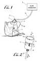
- FIG. 1illustrates a patient wearing a mask according to one preferred aspect of the invention that is connected to a source of positive airway pressure, which in this case, is a flow generator.
- FIG. 2illustrates an isometric view of the valve according to a preferred aspect of the invention.
- FIG. 3shows a cross-sectional view of the valve. In this view the pressure from the flow generator exceeds the threshold pressure of the valve, causing exhausting of gas through a first flowpath.
- FIG. 4shows a cross-sectional view of the valve. In this view the pressure from the flow generator is below the threshold pressure of the valve, causing exhausting of gas through a second flowpath.
- FIG. 5is a graph illustrating the pressure within a mask employing the valve across a range of flow rates.
- FIG. 1illustrates a patient 2 wearing a mask 4 that is secured to the head of the patient 2 using elastic straps 6 .
- the straps 6aid in forming an air-tight seal between the patient's face and the mask 4 .
- FIG. 1explicitly shows a nasal mask 4 , it should be understood that other types of masks 4 such as mouth masks or full face masks may also be used.
- the mask 4is connected to a source of positive airway pressure 8 via flexible tubing 10 .
- the source of positive airway pressure 8can be any number of devices.
- the source of positive airway pressure 8is a flow generator. Flow generators produce a pressurized flow of air by using an electrical motor that is coupled to a turbine or impeller that supplies airflow through the flexible tubing 10 .
- the source of positive airway pressure 8may include a compressed gas that is stored within, for example, a pressurized cylinder.
- the compressed gasmay also be delivered via a dedicated wall line, such as those found in hospitals and medical clinics. All that is required for the source of positive airway pressure 8 is that the device be able to supply gas to the patient at physiologic flow rates.
- the source of positive airway pressure 8may be coupled to a separate gas such as enriched oxygen, that aids in treating patients suffering from chronic obstructive pulmonary diseases.
- the mask 4 in FIG. 1has a valve 12 that serves several functions.
- the valve 12maintains a substantially constant pressure at the mask 4 when the pressure supplied by the source of positive airway pressure 8 is above the threshold pressure (discussed in detail below) of the valve 12 .
- the term “substantially constant”is meant to indicate that pressure fluctuations in the mask 4 are less than about +/ ⁇ 1 cm H 2 O.
- the valve 12also has a fail-safe feature in that, at low pressures (i.e., pressures below the threshold pressure of the valve 12 ), the exhaust gas flowpath through the valve 12 changes to allow exhaled gas to quickly exit from the mask 4 .
- the valve 12prevents the patient 2 from re-breathing his or her own exhaled gas. This is particularly important because it eliminates the possibility of asphyxiation should the source of positive airway pressure 8 stop delivering gas to the patient 2 .
- FIG. 1shows the valve 12 located in the mask 4 (the preferred location), the valve 12 can also be disposed at any location between the mask 4 and the source of positive airway pressure 8 .
- FIG. 2shows one preferred embodiment of the valve 12 .
- the valve 12includes a valve body 14 that has a central lumen 16 through which gases flow in the direction of arrow A when the pressure in the mask 4 exceeds the threshold pressure of the valve 12 .
- the valve body 14holds a moveable piston 18 that is translatable in the directions of arrow B.
- the piston 18is spring-biased toward the valve body 14 (in the direction of arrow C) by a spring 20 .
- the spring 20is under compression to bias the piston 18 toward the valve body 14 . It should be understood, however, that the spring 20 may be held in tension in an alternative construction to bias the piston 18 toward the valve body 14 .
- valve body 14includes a floating valve seat 22 , against which, the piston 18 is held when the pressure in the mask 4 is below the threshold pressure of the valve 12 .
- the floating valve seat 22is disposed within a recessed area 24 of the valve body 14 and is movable in the directions of arrow B between first and second positions, depending on the pressure inside the mask 4 (or within the flexible tubing 10 if the valve 12 is disposed between the mask 4 and the source of positive airway pressure 8 ).
- a valve seat stop 26 on either end of the floating valve seat 22limits the extent of movement of the floating valve seat 22 .
- the valve body 14includes a plurality of ports 28 that allow gases to communicate with the recessed area 24 holding the floating valve seat 22 . Depending on the position of the floating valve seat 22 , which is described in more detail below, gas is either prevented or permitted to exhaust from the valve 12 via the ports 28 .
- FIG. 3illustrates a cross-sectional view of the valve 12 shown in FIG. 2 .
- the valve 12is experiencing a pressure that exceeds the threshold value of the valve 12 .
- the pressure of the gas entering the ports 28pushes against the floating valve seat 22 and moves the floating valve seat 22 to a first position.
- this first positionwhich is shown in FIG. 3, the floating valve seat 22 is pushed against one of the valve seat stops 26 .
- gascannot exit the valve 12 via the ports 28 and recessed area 24 .
- the pressure of the gas contained thereinpushes on the piston 18 and causes the piston 18 to lift away from the surface of the floating valve seat 22 .
- a gapis formed between the piston 18 and the floating valve seat 22 through which gases pass freely.
- gasis continuously exhausted through this gap.
- This gapforms a first exhaust flowpath of the valve 12 .
- the piston 18is preferably made from a light weight material such as, for example, polycarbonate.
- the spring 20preferably has a low spring constant. By using a spring 20 with a low spring constant, the displacement of the piston 18 will be relatively large for a small change in pressure, thereby ensuring good pressure regulation.
- the valve 12maintains a substantially constant pressure within the mask 4 as follows.
- the piston 18is lifted off of the floating valve seat 22 .
- the pressure in the mask 4starts to rise, for example, when the patient 2 exhales, the piston 18 moves further away from the floating valve seat 22 , thereby exhausting additional gas and, therefore, excess pressure from the valve 12 .
- FIG. 4illustrates the valve 12 when the pressure falls below the valve's 12 threshold value.
- the gases pushing against the piston 18cannot overcome the biasing force of the spring 20 . Consequently, the piston 18 moves in the direction of arrow C shown in FIG. 2 until the piston 18 engages with the floating valve seat 22 .
- the piston 18continues to move in the direction of arrow C and pushes the floating valve seat 22 from the first position to a second position (shown in FIG. 4) in which the floating valve seat 22 abuts the valve seat stop 26 .
- gasexits the valve 12 via the ports 28 and recessed area 24 as is shown in FIG. 4 .
- the ports 28 and recessed area 24form a second, alternative exhaust flowpath. Gas does not, however, exit the valve 12 from the valve lumen 16 because a seal is formed between the piston 18 and the floating valve seat 22 .
- FIG. 5graphically illustrates the ability of the valve 12 to maintain a substantially constant pressure over a wide range of flow rates.
- the threshold value of the valve 12 used to generate the datais about 6 cm H 2 O.
- the valve 12produces a substantially constant flow rate within the range of about 20 liters/minute to about 100 liters/minute.
- the floating valve seat 22is in the first position (shown in FIG. 3) and gas is exhausted to the atmosphere from the gap formed between the piston 18 and the floating valve seat 22 .
- the floating valve seat 22is pushed by the spring-biased piston 18 into the second position, thereby opening an alternative pathway (i.e., through ports 28 and recessed area 24 ) for gases to flow through.
- the valve 12 or mask 4(including valve 12 ) is prescribed to the patient 2 with a preset threshold value.
- a preset threshold valueFor example, some patients 2 might be prescribed 10 cm H 2 O pressure.
- a valve 12 /mask 4 preset to 10 cm H 2 Ois prescribed.
- the preset threshold pressureis within the range of about 3 cm H 2 O to about 20 cm H 2 O.
Landscapes
- Health & Medical Sciences (AREA)
- Pulmonology (AREA)
- Emergency Medicine (AREA)
- Engineering & Computer Science (AREA)
- Anesthesiology (AREA)
- Biomedical Technology (AREA)
- Heart & Thoracic Surgery (AREA)
- Hematology (AREA)
- Life Sciences & Earth Sciences (AREA)
- Animal Behavior & Ethology (AREA)
- General Health & Medical Sciences (AREA)
- Public Health (AREA)
- Veterinary Medicine (AREA)
- Respiratory Apparatuses And Protective Means (AREA)
Abstract
Description
Claims (14)
Priority Applications (1)
| Application Number | Priority Date | Filing Date | Title |
|---|---|---|---|
| US10/231,859US6766800B2 (en) | 2002-08-30 | 2002-08-30 | Pressure regulating valve for use in continuous positive airway pressure devices |
Applications Claiming Priority (1)
| Application Number | Priority Date | Filing Date | Title |
|---|---|---|---|
| US10/231,859US6766800B2 (en) | 2002-08-30 | 2002-08-30 | Pressure regulating valve for use in continuous positive airway pressure devices |
Publications (2)
| Publication Number | Publication Date |
|---|---|
| US20040040563A1 US20040040563A1 (en) | 2004-03-04 |
| US6766800B2true US6766800B2 (en) | 2004-07-27 |
Family
ID=31976843
Family Applications (1)
| Application Number | Title | Priority Date | Filing Date |
|---|---|---|---|
| US10/231,859Expired - LifetimeUS6766800B2 (en) | 2002-08-30 | 2002-08-30 | Pressure regulating valve for use in continuous positive airway pressure devices |
Country Status (1)
| Country | Link |
|---|---|
| US (1) | US6766800B2 (en) |
Cited By (68)
| Publication number | Priority date | Publication date | Assignee | Title |
|---|---|---|---|---|
| US20040134498A1 (en)* | 2001-10-25 | 2004-07-15 | Roger Strickland | Nasal cannula |
| US20040182397A1 (en)* | 2003-03-21 | 2004-09-23 | Innomed Technologies, Inc. | Nasal interface including ventilation insert |
| US20040255943A1 (en)* | 2003-06-23 | 2004-12-23 | Make Morris | System and method for providing a breathing gas |
| US20050028823A1 (en)* | 2000-03-13 | 2005-02-10 | Wood Thomas J. | Nasal ventilation interface |
| US20050028821A1 (en)* | 2003-08-06 | 2005-02-10 | Wood Thomas J. | Nasal interface and system including ventilation insert |
| US20050039757A1 (en)* | 1999-03-13 | 2005-02-24 | Wood Thomas J. | Ventilation interface for sleep apnea therapy |
| US20050045182A1 (en)* | 2003-08-06 | 2005-03-03 | Wood Thomas J. | Nasal interface and system including ventilation insert |
| US20050126574A1 (en)* | 2000-03-13 | 2005-06-16 | Wood Thomas J. | Ventilation interface for sleep apnea therapy |
| US20050133040A1 (en)* | 2003-09-10 | 2005-06-23 | Wood Thomas J. | Nasal interface and system including ventilation insert |
| US20050235999A1 (en)* | 2004-04-23 | 2005-10-27 | Wood Thomas J | Nasal ventilation interface and system |
| US20050236000A1 (en)* | 2003-08-05 | 2005-10-27 | Wood Thomas J | Nasal ventilation interface and system |
| US20050268913A1 (en)* | 2003-06-23 | 2005-12-08 | Make Morris | System and method for providing a breathing gas |
| US20050279358A1 (en)* | 2000-09-28 | 2005-12-22 | Richey Joseph B Ii | Carbon dioxide-based bi-level CPAP control |
| US20060124131A1 (en)* | 2004-12-10 | 2006-06-15 | Respcare, Inc. | Hybrid ventilation mask with nasal interface and method for configuring such a mask |
| US20060237017A1 (en)* | 2003-12-31 | 2006-10-26 | Resmed Limited | Compact oronasal patient interface |
| US7191781B2 (en) | 2003-08-05 | 2007-03-20 | Innomed Technologies, Inc. | Nasal ventilation interface and system |
| USD550836S1 (en) | 2005-07-06 | 2007-09-11 | Respcare, Inc. | Ventilation interface |
| USD551340S1 (en) | 2000-03-13 | 2007-09-18 | Innomed Technologies, Inc. | Nasal interface |
| US20070272249A1 (en)* | 2006-05-10 | 2007-11-29 | Sanjay Chandran | Ventilation interface |
| US20070277825A1 (en)* | 2006-04-10 | 2007-12-06 | Bordewick Steven S | Apparatus and methods for providing humidity in respiratory therapy |
| US20070289642A1 (en)* | 2004-11-09 | 2007-12-20 | Masco Corporation Of Indiana | Device for dynamic control of a water flow |
| US20080129063A1 (en)* | 2006-12-01 | 2008-06-05 | Samsung Electronics Co., Ltd. | Vacuum type pickup apparatus and vacuum type pickup Method |
| US20080251079A1 (en)* | 2007-04-13 | 2008-10-16 | Invacare Corporation | Apparatus and method for providing positive airway pressure |
| US20080257358A1 (en)* | 2007-04-23 | 2008-10-23 | Goodhealth, Llc | Passive Treatment Device |
| USD583047S1 (en) | 2007-04-09 | 2008-12-16 | Respcare, Inc. | Ventilation interface |
| US20090032022A1 (en)* | 2007-07-31 | 2009-02-05 | Peter Chi Fai Ho | Pressure Reducing Valve With Flexible Cuff |
| USD591419S1 (en) | 2008-01-08 | 2009-04-28 | Mergenet Solutions, Inc. | Ventilation portion of a ventilation apparatus |
| US7559327B2 (en) | 2005-05-31 | 2009-07-14 | Respcare, Inc. | Ventilation interface |
| USD597199S1 (en) | 2006-04-28 | 2009-07-28 | Resmed Limited | Respiratory mask frame |
| USD623288S1 (en) | 2006-04-28 | 2010-09-07 | Resmed Limited | Patient interface |
| US7958893B2 (en) | 2001-09-07 | 2011-06-14 | Resmed Limited | Cushion for a respiratory mask assembly |
| US8136525B2 (en) | 2004-12-24 | 2012-03-20 | Resmed Limited | Mask system |
| US8251876B2 (en) | 2008-04-22 | 2012-08-28 | Hill-Rom Services, Inc. | Breathing exercise apparatus |
| US8251066B1 (en)* | 2004-12-22 | 2012-08-28 | Ric Investments, Llc | Exhalation port with built-in entrainment valve |
| US8261742B2 (en) | 2007-08-23 | 2012-09-11 | Invacare Corporation | Method and apparatus for adjusting desired pressure in positive airway pressure devices |
| US8261745B2 (en) | 2004-12-10 | 2012-09-11 | Respcare, Inc. | Ventilation interface |
| US8291906B2 (en) | 2008-06-04 | 2012-10-23 | Resmed Limited | Patient interface systems |
| US8297285B2 (en) | 2006-07-28 | 2012-10-30 | Resmed Limited | Delivery of respiratory therapy |
| US8327848B2 (en) | 2006-09-28 | 2012-12-11 | Ric Investments, Llc | Pressure reducing valve |
| US8485192B2 (en) | 2005-01-12 | 2013-07-16 | Resmed Limited | Cushion for patient interface |
| US8517023B2 (en) | 2007-01-30 | 2013-08-27 | Resmed Limited | Mask system with interchangeable headgear connectors |
| US8522784B2 (en) | 2008-03-04 | 2013-09-03 | Resmed Limited | Mask system |
| USD695890S1 (en)* | 2012-04-24 | 2013-12-17 | O-Two Medical Technologies Inc. | Disposable CPAP connector for a patient facemask |
| US8789532B2 (en) | 2006-03-10 | 2014-07-29 | Respcare, Inc. | Ventilation mask |
| US8807135B2 (en) | 2004-06-03 | 2014-08-19 | Resmed Limited | Cushion for a patient interface |
| US8839791B2 (en) | 2011-06-22 | 2014-09-23 | Breathe Technologies, Inc. | Ventilation mask with integrated piloted exhalation valve |
| US8869797B2 (en) | 2007-04-19 | 2014-10-28 | Resmed Limited | Cushion and cushion to frame assembly mechanism for patient interface |
| US8869798B2 (en) | 2008-09-12 | 2014-10-28 | Resmed Limited | Foam-based interfacing structure method and apparatus |
| US8905031B2 (en) | 2008-06-04 | 2014-12-09 | Resmed Limited | Patient interface systems |
| US8944061B2 (en) | 2005-10-14 | 2015-02-03 | Resmed Limited | Cushion to frame assembly mechanism |
| US9038634B2 (en) | 2011-06-22 | 2015-05-26 | Breathe Technologies, Inc. | Ventilation mask with integrated piloted exhalation valve |
| US9138553B2 (en) | 2000-03-13 | 2015-09-22 | Innomed Technologies, Inc. | Ventilation interface for sleep apnea therapy |
| US9162034B2 (en) | 2006-07-28 | 2015-10-20 | Resmed Limited | Delivery of respiratory therapy |
| US9180271B2 (en) | 2012-03-05 | 2015-11-10 | Hill-Rom Services Pte. Ltd. | Respiratory therapy device having standard and oscillatory PEP with nebulizer |
| US9381316B2 (en) | 2005-10-25 | 2016-07-05 | Resmed Limited | Interchangeable mask assembly |
| US9480809B2 (en) | 2007-07-30 | 2016-11-01 | Resmed Limited | Patient interface |
| US9486602B2 (en) | 2011-06-22 | 2016-11-08 | Breathe Technologies, Inc. | Ventilation mask with integrated piloted exhalation valve and method of ventilating a patient using the same |
| US9987450B2 (en) | 2008-03-04 | 2018-06-05 | Resmed Limited | Interface including a foam cushioning element |
| US10166357B2 (en) | 2006-12-15 | 2019-01-01 | Resmed Limited | Delivery of respiratory therapy with nasal interface |
| US10307554B2 (en) | 2002-11-06 | 2019-06-04 | Resmed Limited | Mask and components thereof |
| US10335571B2 (en) | 2010-03-25 | 2019-07-02 | Resmed Paris Sas | Breathable gas inlet control device for respiratory treatment apparatus |
| US10786642B2 (en) | 2009-01-30 | 2020-09-29 | ResMed Pty Ltd | Patient interface structure and method/tool for manufacturing same |
| US10905836B2 (en) | 2015-04-02 | 2021-02-02 | Hill-Rom Services Pte. Ltd. | Manifold for respiratory device |
| US11129953B2 (en) | 2008-03-04 | 2021-09-28 | ResMed Pty Ltd | Foam respiratory mask |
| US11331447B2 (en) | 2008-03-04 | 2022-05-17 | ResMed Pty Ltd | Mask system with snap-fit shroud |
| US11389605B2 (en) | 2018-02-12 | 2022-07-19 | Vortran Medical Technology I, Inc. | Low flow percussive respiratory apparatus and related treatment |
| US11724050B2 (en) | 2013-12-17 | 2023-08-15 | Somnetics International, Inc. | Humidification system and positive airway pressure apparatus incorporating same |
| USD1048571S1 (en) | 2021-10-07 | 2024-10-22 | Masimo Corporation | Bite block |
Families Citing this family (10)
| Publication number | Priority date | Publication date | Assignee | Title |
|---|---|---|---|---|
| US7607437B2 (en)* | 2003-08-04 | 2009-10-27 | Cardinal Health 203, Inc. | Compressor control system and method for a portable ventilator |
| ES2592262T3 (en)* | 2003-08-04 | 2016-11-29 | Carefusion 203, Inc. | Portable respirator system |
| US8118024B2 (en) | 2003-08-04 | 2012-02-21 | Carefusion 203, Inc. | Mechanical ventilation system utilizing bias valve |
| US11696691B2 (en)* | 2008-05-01 | 2023-07-11 | Hill-Rom Services, Inc. | Monitoring, predicting, and treating clinical episodes |
| CA2724773C (en)* | 2008-05-20 | 2017-05-30 | 5I Sciences | Device and method for opening an airway |
| WO2010124191A2 (en)* | 2009-04-24 | 2010-10-28 | New York University | System and method for circuits to allow cpap to provide zero pressure |
| EP3851146B1 (en) | 2011-08-22 | 2025-04-30 | ResMed Pty Ltd | Manufactured to shape headgear and masks |
| GB2549437B (en)* | 2011-12-09 | 2018-02-28 | Intersurgical Ag | Valve for respiratory masks |
| CN111867527A (en)* | 2018-03-12 | 2020-10-30 | 奥温特斯医疗有限公司 | Oral appliance and valve arrangement |
| WO2021183723A1 (en)* | 2020-03-11 | 2021-09-16 | Pneuma Therapeutics, Inc. | New nasal respiratory apparatus |
Citations (15)
| Publication number | Priority date | Publication date | Assignee | Title |
|---|---|---|---|---|
| US4655213A (en) | 1983-10-06 | 1987-04-07 | New York University | Method and apparatus for the treatment of obstructive sleep apnea |
| US4926855A (en)* | 1984-09-21 | 1990-05-22 | Interspiro Ab | Respirator |
| US5065756A (en) | 1987-12-22 | 1991-11-19 | New York University | Method and apparatus for the treatment of obstructive sleep apnea |
| US5109840A (en)* | 1991-02-14 | 1992-05-05 | Specialty Packaging Licensing Company | Resuscitator having directional control valve with internal "PEEP" adjustment valve |
| US5134995A (en) | 1989-05-19 | 1992-08-04 | Puritan-Bennett Corporation | Inspiratory airway pressure system with admittance determining apparatus and method |
| US5694923A (en) | 1996-08-30 | 1997-12-09 | Respironics, Inc. | Pressure control in a blower-based ventilator |
| US5730122A (en)* | 1996-11-12 | 1998-03-24 | Cprx, Inc. | Heart failure mask and methods for increasing negative intrathoracic pressures |
| US5878743A (en) | 1996-09-23 | 1999-03-09 | Respironics, Inc. | Pressure sensitive flow control valve |
| US6006748A (en)* | 1996-10-16 | 1999-12-28 | Resmed Limited | Vent valve apparatus |
| US6102038A (en)* | 1998-05-15 | 2000-08-15 | Pulmonetic Systems, Inc. | Exhalation valve for mechanical ventilator |
| US6182657B1 (en) | 1995-09-18 | 2001-02-06 | Resmed Limited | Pressure control in CPAP treatment or assisted respiration |
| US6189532B1 (en)* | 1996-12-16 | 2001-02-20 | Resmed Limited | Valve for use in a gas delivery system |
| US6253764B1 (en) | 1996-05-08 | 2001-07-03 | Resmed, Ltd. | Control of delivery pressure in CPAP treatment or assisted respiration |
| US6343603B1 (en) | 1998-10-09 | 2002-02-05 | Fisher & Paykel Limited | Connector |
| US6371117B1 (en) | 1998-06-15 | 2002-04-16 | Siemens Elema Ab | Directional valve |
- 2002
- 2002-08-30USUS10/231,859patent/US6766800B2/ennot_activeExpired - Lifetime
Patent Citations (16)
| Publication number | Priority date | Publication date | Assignee | Title |
|---|---|---|---|---|
| US4655213A (en) | 1983-10-06 | 1987-04-07 | New York University | Method and apparatus for the treatment of obstructive sleep apnea |
| US4926855A (en)* | 1984-09-21 | 1990-05-22 | Interspiro Ab | Respirator |
| US5065756A (en) | 1987-12-22 | 1991-11-19 | New York University | Method and apparatus for the treatment of obstructive sleep apnea |
| USRE35339E (en) | 1987-12-22 | 1996-10-01 | New York University | Method and apparatus for the treatment of obstructive sleep apnea |
| US5134995A (en) | 1989-05-19 | 1992-08-04 | Puritan-Bennett Corporation | Inspiratory airway pressure system with admittance determining apparatus and method |
| US5109840A (en)* | 1991-02-14 | 1992-05-05 | Specialty Packaging Licensing Company | Resuscitator having directional control valve with internal "PEEP" adjustment valve |
| US6182657B1 (en) | 1995-09-18 | 2001-02-06 | Resmed Limited | Pressure control in CPAP treatment or assisted respiration |
| US6253764B1 (en) | 1996-05-08 | 2001-07-03 | Resmed, Ltd. | Control of delivery pressure in CPAP treatment or assisted respiration |
| US5694923A (en) | 1996-08-30 | 1997-12-09 | Respironics, Inc. | Pressure control in a blower-based ventilator |
| US5878743A (en) | 1996-09-23 | 1999-03-09 | Respironics, Inc. | Pressure sensitive flow control valve |
| US6006748A (en)* | 1996-10-16 | 1999-12-28 | Resmed Limited | Vent valve apparatus |
| US5730122A (en)* | 1996-11-12 | 1998-03-24 | Cprx, Inc. | Heart failure mask and methods for increasing negative intrathoracic pressures |
| US6189532B1 (en)* | 1996-12-16 | 2001-02-20 | Resmed Limited | Valve for use in a gas delivery system |
| US6102038A (en)* | 1998-05-15 | 2000-08-15 | Pulmonetic Systems, Inc. | Exhalation valve for mechanical ventilator |
| US6371117B1 (en) | 1998-06-15 | 2002-04-16 | Siemens Elema Ab | Directional valve |
| US6343603B1 (en) | 1998-10-09 | 2002-02-05 | Fisher & Paykel Limited | Connector |
Non-Patent Citations (7)
Cited By (212)
| Publication number | Priority date | Publication date | Assignee | Title |
|---|---|---|---|---|
| US20050039757A1 (en)* | 1999-03-13 | 2005-02-24 | Wood Thomas J. | Ventilation interface for sleep apnea therapy |
| US6997177B2 (en) | 1999-03-13 | 2006-02-14 | Inno Med Technologies, Inc. | Ventilation interface for sleep apnea therapy |
| US7188624B2 (en) | 2000-03-13 | 2007-03-13 | Innomed Technologies Inc. | Ventilation interface for sleep apnea therapy |
| US20050028823A1 (en)* | 2000-03-13 | 2005-02-10 | Wood Thomas J. | Nasal ventilation interface |
| US9919121B2 (en) | 2000-03-13 | 2018-03-20 | Innomed Healthscience, Inc. | Ventilation interface for sleep apnea therapy |
| US7059328B2 (en) | 2000-03-13 | 2006-06-13 | Innomed Technologies, Inc. | Ventilation interface for sleep apnea therapy |
| US20050126574A1 (en)* | 2000-03-13 | 2005-06-16 | Wood Thomas J. | Ventilation interface for sleep apnea therapy |
| US6994089B2 (en) | 2000-03-13 | 2006-02-07 | Innomed Technologies, Inc | Nasal ventilation interface |
| USD551340S1 (en) | 2000-03-13 | 2007-09-18 | Innomed Technologies, Inc. | Nasal interface |
| US9138553B2 (en) | 2000-03-13 | 2015-09-22 | Innomed Technologies, Inc. | Ventilation interface for sleep apnea therapy |
| US20050279358A1 (en)* | 2000-09-28 | 2005-12-22 | Richey Joseph B Ii | Carbon dioxide-based bi-level CPAP control |
| US8640701B2 (en) | 2000-09-28 | 2014-02-04 | Invacare Corporation | Carbon dioxide-based bi-level CPAP control |
| US10850057B2 (en) | 2001-09-07 | 2020-12-01 | ResMed Pty Ltd | Cushion for a respiratory mask assembly |
| US7958893B2 (en) | 2001-09-07 | 2011-06-14 | Resmed Limited | Cushion for a respiratory mask assembly |
| US9724488B2 (en) | 2001-09-07 | 2017-08-08 | Resmed Limited | Cushion for a respiratory mask assembly |
| US8733358B2 (en) | 2001-09-07 | 2014-05-27 | Resmed Limited | Cushion for a respiratory mask assembly |
| US20040134498A1 (en)* | 2001-10-25 | 2004-07-15 | Roger Strickland | Nasal cannula |
| US10940283B2 (en) | 2002-11-06 | 2021-03-09 | ResMed Pty Ltd | Mask and components thereof |
| US11406784B2 (en) | 2002-11-06 | 2022-08-09 | ResMed Pty Ltd | Mask and components thereof |
| US11666725B2 (en) | 2002-11-06 | 2023-06-06 | ResMed Pty Ltd | Mask and components thereof |
| US10307554B2 (en) | 2002-11-06 | 2019-06-04 | Resmed Limited | Mask and components thereof |
| US20040182397A1 (en)* | 2003-03-21 | 2004-09-23 | Innomed Technologies, Inc. | Nasal interface including ventilation insert |
| US7152598B2 (en)* | 2003-06-23 | 2006-12-26 | Invacare Corporation | System and method for providing a breathing gas |
| US20050268913A1 (en)* | 2003-06-23 | 2005-12-08 | Make Morris | System and method for providing a breathing gas |
| US7621270B2 (en) | 2003-06-23 | 2009-11-24 | Invacare Corp. | System and method for providing a breathing gas |
| US20040255943A1 (en)* | 2003-06-23 | 2004-12-23 | Make Morris | System and method for providing a breathing gas |
| US20100065055A1 (en)* | 2003-06-23 | 2010-03-18 | Invacare Corporation | System and method for providing a breathing gas |
| US8066004B2 (en) | 2003-06-23 | 2011-11-29 | Invacare Corporation | System and method for providing a breathing gas |
| US7191781B2 (en) | 2003-08-05 | 2007-03-20 | Innomed Technologies, Inc. | Nasal ventilation interface and system |
| US7234465B2 (en) | 2003-08-05 | 2007-06-26 | Innomed Technologies, Inc. | Nasal ventilation interface and system |
| US20060150982A1 (en)* | 2003-08-05 | 2006-07-13 | Wood Thomas J | Nasal ventilation interface and system |
| US20050236000A1 (en)* | 2003-08-05 | 2005-10-27 | Wood Thomas J | Nasal ventilation interface and system |
| US20050045182A1 (en)* | 2003-08-06 | 2005-03-03 | Wood Thomas J. | Nasal interface and system including ventilation insert |
| US20050028821A1 (en)* | 2003-08-06 | 2005-02-10 | Wood Thomas J. | Nasal interface and system including ventilation insert |
| US7000613B2 (en) | 2003-08-06 | 2006-02-21 | Innomed Technologies, Inc. | Nasal interface and system including ventilation insert |
| US7472707B2 (en) | 2003-08-06 | 2009-01-06 | Innomed Technologies, Inc. | Nasal interface and system including ventilation insert |
| US20050133040A1 (en)* | 2003-09-10 | 2005-06-23 | Wood Thomas J. | Nasal interface and system including ventilation insert |
| US20060237017A1 (en)* | 2003-12-31 | 2006-10-26 | Resmed Limited | Compact oronasal patient interface |
| US10569042B2 (en) | 2003-12-31 | 2020-02-25 | ResMed Pty Ltd | Compact oronasal patient interface |
| US9067033B2 (en) | 2003-12-31 | 2015-06-30 | Resmed Limited | Compact oronasal patient interface |
| US20070144525A1 (en)* | 2003-12-31 | 2007-06-28 | Resmed Limited | Compact oronasal patient interface |
| US9220860B2 (en) | 2003-12-31 | 2015-12-29 | Resmed Limited | Compact oronasal patient interface |
| US11077275B2 (en) | 2003-12-31 | 2021-08-03 | ResMed Pty Ltd | Compact oronasal patient interface |
| US7658189B2 (en) | 2003-12-31 | 2010-02-09 | Resmed Limited | Compact oronasal patient interface |
| US11633562B2 (en) | 2003-12-31 | 2023-04-25 | ResMed Pty Ltd | Compact oronasal patient interface |
| US11229762B2 (en) | 2003-12-31 | 2022-01-25 | ResMed Pty Ltd | Compact oronasal patient interface |
| US7708017B2 (en) | 2003-12-31 | 2010-05-04 | Resmed Limited | Compact oronasal patient interface |
| US10646677B2 (en) | 2003-12-31 | 2020-05-12 | ResMed Pty Ltd | Compact oronasal patient interface |
| US10806886B2 (en) | 2003-12-31 | 2020-10-20 | ResMed Pty Ltd | Compact oronasal patient interface |
| US7942148B2 (en) | 2003-12-31 | 2011-05-17 | Resmed Limited | Compact oronasal patient interface |
| US20050235999A1 (en)* | 2004-04-23 | 2005-10-27 | Wood Thomas J | Nasal ventilation interface and system |
| US8807135B2 (en) | 2004-06-03 | 2014-08-19 | Resmed Limited | Cushion for a patient interface |
| US9238116B2 (en) | 2004-06-03 | 2016-01-19 | Redmed Limited | Cushion for a patient interface |
| US7681598B2 (en)* | 2004-11-09 | 2010-03-23 | Masco | Device for dynamic control of a water flow |
| US20070289642A1 (en)* | 2004-11-09 | 2007-12-20 | Masco Corporation Of Indiana | Device for dynamic control of a water flow |
| US8261745B2 (en) | 2004-12-10 | 2012-09-11 | Respcare, Inc. | Ventilation interface |
| US8042539B2 (en) | 2004-12-10 | 2011-10-25 | Respcare, Inc. | Hybrid ventilation mask with nasal interface and method for configuring such a mask |
| US20060124131A1 (en)* | 2004-12-10 | 2006-06-15 | Respcare, Inc. | Hybrid ventilation mask with nasal interface and method for configuring such a mask |
| US8251066B1 (en)* | 2004-12-22 | 2012-08-28 | Ric Investments, Llc | Exhalation port with built-in entrainment valve |
| US8136525B2 (en) | 2004-12-24 | 2012-03-20 | Resmed Limited | Mask system |
| US8567404B2 (en) | 2005-01-12 | 2013-10-29 | Resmed Limited | Cushion for patient interface |
| US8485192B2 (en) | 2005-01-12 | 2013-07-16 | Resmed Limited | Cushion for patient interface |
| US9295800B2 (en) | 2005-01-12 | 2016-03-29 | Resmed Limited | Cushion for patient interface |
| US8613280B2 (en) | 2005-01-12 | 2013-12-24 | Resmed Limited | Cushion for patient interface |
| US8616211B2 (en) | 2005-01-12 | 2013-12-31 | Resmed Limited | Cushion for patient interface |
| US8578935B2 (en) | 2005-01-12 | 2013-11-12 | Resmed Limited | Cushion for patient interface |
| US8573215B2 (en) | 2005-01-12 | 2013-11-05 | Resmed Limited | Cushion for patient interface |
| US11607515B2 (en) | 2005-01-12 | 2023-03-21 | ResMed Pty Ltd | Cushion for patient interface |
| US8573214B2 (en) | 2005-01-12 | 2013-11-05 | Resmed Limited | Cushion for patient interface |
| US8573213B2 (en) | 2005-01-12 | 2013-11-05 | Resmed Limited | Cushion for patient interface |
| US10456544B2 (en) | 2005-01-12 | 2019-10-29 | ResMed Pty Ltd | Cushion for patient interface |
| US8550081B2 (en) | 2005-01-12 | 2013-10-08 | Resmed Limited | Cushion for patient interface |
| US8613281B2 (en) | 2005-01-12 | 2013-12-24 | Resmed Limited | Cushion for patient interface |
| US8550083B2 (en) | 2005-01-12 | 2013-10-08 | Resmed Limited | Cushion for patient interface |
| US8550082B2 (en) | 2005-01-12 | 2013-10-08 | Resmed Limited | Cushion for patient interface |
| US8555885B2 (en) | 2005-01-12 | 2013-10-15 | Resmed Limited | Cushion for patient interface |
| US7559327B2 (en) | 2005-05-31 | 2009-07-14 | Respcare, Inc. | Ventilation interface |
| US10864340B2 (en) | 2005-06-06 | 2020-12-15 | ResMed Pty Ltd | Mask system |
| US10561812B2 (en) | 2005-06-06 | 2020-02-18 | ResMed Pty Ltd | Mask system |
| US10569041B2 (en) | 2005-06-06 | 2020-02-25 | ResMed Pty Ltd | Mask system |
| US8915251B2 (en) | 2005-06-06 | 2014-12-23 | Resmed Limited | Mask system |
| US10603461B2 (en) | 2005-06-06 | 2020-03-31 | ResMed Pty Ltd | Mask system |
| US9032955B2 (en) | 2005-06-06 | 2015-05-19 | Resmed Limited | Mask system |
| USD550836S1 (en) | 2005-07-06 | 2007-09-11 | Respcare, Inc. | Ventilation interface |
| US8944061B2 (en) | 2005-10-14 | 2015-02-03 | Resmed Limited | Cushion to frame assembly mechanism |
| US12011540B2 (en) | 2005-10-14 | 2024-06-18 | ResMed Pty Ltd | Cushion/frame sub-assembly connectable to outer frame |
| US11633564B2 (en) | 2005-10-14 | 2023-04-25 | ResMed Pty Ltd | Cushion to frame assembly mechanism |
| US10137270B2 (en) | 2005-10-14 | 2018-11-27 | Resmed Limited | Cushion to frame assembly mechanism |
| US11833305B2 (en) | 2005-10-14 | 2023-12-05 | ResMed Pty Ltd | Cushion/frame assembly for a patient interface |
| US11369765B2 (en) | 2005-10-14 | 2022-06-28 | ResMed Pty Ltd | Cushion to frame assembly mechanism |
| US10434273B2 (en) | 2005-10-14 | 2019-10-08 | ResMed Pty Ltd | Cushion to frame assembly mechanism |
| US11529487B2 (en) | 2005-10-14 | 2022-12-20 | ResMed Pty Ltd | Cushion to frame assembly mechanism |
| US9381316B2 (en) | 2005-10-25 | 2016-07-05 | Resmed Limited | Interchangeable mask assembly |
| US9962510B2 (en) | 2005-10-25 | 2018-05-08 | Resmed Limited | Respiratory mask assembly |
| US11052211B2 (en) | 2005-10-25 | 2021-07-06 | ResMed Pty Ltd | Interchangeable mask assembly |
| US11596757B2 (en) | 2005-10-25 | 2023-03-07 | ResMed Pty Ltd | Interchangeable mask assembly |
| US10183138B2 (en) | 2005-10-25 | 2019-01-22 | Resmed Limited | Interchangeable mask assembly |
| US11890418B2 (en) | 2005-10-25 | 2024-02-06 | ResMed Pty Ltd | Interchangeable mask assembly |
| USD583049S1 (en) | 2005-12-23 | 2008-12-16 | Respcare, Inc. | Ventilation interface |
| USD583048S1 (en) | 2005-12-23 | 2008-12-16 | Respcare, Inc. | Ventilation interface |
| USD597659S1 (en) | 2005-12-23 | 2009-08-04 | Respcare, Inc. | Ventilation interface |
| US8789532B2 (en) | 2006-03-10 | 2014-07-29 | Respcare, Inc. | Ventilation mask |
| US20070277825A1 (en)* | 2006-04-10 | 2007-12-06 | Bordewick Steven S | Apparatus and methods for providing humidity in respiratory therapy |
| US9597477B2 (en) | 2006-04-10 | 2017-03-21 | Somnetics Global Pte. Ltd. | Apparatus and methods for providing humidity in respiratory therapy |
| US8602025B2 (en) | 2006-04-10 | 2013-12-10 | Somnetics Global Pte. Ltd. | Apparatus and methods for providing humidity in respiratory therapy |
| US8074645B2 (en) | 2006-04-10 | 2011-12-13 | Somnetics Global Pte. Ltd. | Apparatus and methods for providing humidity in respiratory therapy |
| USD623288S1 (en) | 2006-04-28 | 2010-09-07 | Resmed Limited | Patient interface |
| USD626646S1 (en) | 2006-04-28 | 2010-11-02 | Resmed Limited | Cushion for patient interface |
| USD703312S1 (en) | 2006-04-28 | 2014-04-22 | Resmed Limited | Patient interface |
| USD645557S1 (en) | 2006-04-28 | 2011-09-20 | Resmed Limited | Paired set of prongs for patient interface |
| USD652909S1 (en) | 2006-04-28 | 2012-01-24 | Resmed Limited | Respiratory mask frame |
| USD597199S1 (en) | 2006-04-28 | 2009-07-28 | Resmed Limited | Respiratory mask frame |
| USD659237S1 (en) | 2006-04-28 | 2012-05-08 | Resmed Limited | Patient interface |
| USD669576S1 (en) | 2006-04-28 | 2012-10-23 | Resmed Limited | Respiratory mask frame |
| USD757927S1 (en) | 2006-04-28 | 2016-05-31 | Resmed Limited | Frame for patient interface |
| US20070272249A1 (en)* | 2006-05-10 | 2007-11-29 | Sanjay Chandran | Ventilation interface |
| US8887725B2 (en) | 2006-05-10 | 2014-11-18 | Respcare, Inc. | Ventilation interface |
| US11020558B2 (en) | 2006-07-28 | 2021-06-01 | ResMed Pty Ltd | Delivery of respiratory therapy |
| US10500362B2 (en) | 2006-07-28 | 2019-12-10 | ResMed Pty Ltd | Delivery of respiratory therapy using collapsible inlet conduits |
| US9162034B2 (en) | 2006-07-28 | 2015-10-20 | Resmed Limited | Delivery of respiratory therapy |
| US10556080B2 (en) | 2006-07-28 | 2020-02-11 | ResMed Pty Ltd | Mask system comprising a combined air delivery and stabilizing structure |
| US10974008B2 (en) | 2006-07-28 | 2021-04-13 | ResMed Pty Ltd | Delivery of respiratory therapy using collapsible inlet conduits |
| US10512744B2 (en) | 2006-07-28 | 2019-12-24 | ResMed Pty Ltd | Mask system comprising a combined air delivery and stabilizing structure |
| US10507297B2 (en) | 2006-07-28 | 2019-12-17 | ResMed Pty Ltd | Delivery of respiratory therapy |
| US9827391B2 (en) | 2006-07-28 | 2017-11-28 | Resmed Limited | Delivery of respiratory therapy |
| US11376384B2 (en) | 2006-07-28 | 2022-07-05 | ResMed Pty Ltd | Delivery of respiratory therapy using conduits with varying wall thicknesses |
| US8297285B2 (en) | 2006-07-28 | 2012-10-30 | Resmed Limited | Delivery of respiratory therapy |
| US9937312B2 (en) | 2006-07-28 | 2018-04-10 | Resmed Limited | Delivery of respiratory therapy with foam interface |
| US11135386B2 (en) | 2006-07-28 | 2021-10-05 | ResMed Pty Ltd | Multicomponent respiratory therapy interface |
| US11497873B2 (en) | 2006-07-28 | 2022-11-15 | ResMed Pty Ltd | Delivery of respiratory therapy using a detachable manifold |
| US8327848B2 (en) | 2006-09-28 | 2012-12-11 | Ric Investments, Llc | Pressure reducing valve |
| US20080129063A1 (en)* | 2006-12-01 | 2008-06-05 | Samsung Electronics Co., Ltd. | Vacuum type pickup apparatus and vacuum type pickup Method |
| US11446461B2 (en) | 2006-12-15 | 2022-09-20 | ResMed Pty Ltd | Delivery of respiratory therapy |
| US10166357B2 (en) | 2006-12-15 | 2019-01-01 | Resmed Limited | Delivery of respiratory therapy with nasal interface |
| US10864342B2 (en) | 2007-01-30 | 2020-12-15 | ResMed Pty Ltd | Mask with removable headgear connector |
| US8960196B2 (en) | 2007-01-30 | 2015-02-24 | Resmed Limited | Mask system with interchangeable headgear connectors |
| US12151065B2 (en) | 2007-01-30 | 2024-11-26 | ResMed Pty Ltd | Mask system with removable headgear connector |
| US11992618B2 (en) | 2007-01-30 | 2024-05-28 | ResMed Pty Ltd | Mask with headgear and rigidizers |
| US9937315B2 (en) | 2007-01-30 | 2018-04-10 | Resmed Limited | Mask with removable headgear connector |
| US8517023B2 (en) | 2007-01-30 | 2013-08-27 | Resmed Limited | Mask system with interchangeable headgear connectors |
| USD583047S1 (en) | 2007-04-09 | 2008-12-16 | Respcare, Inc. | Ventilation interface |
| US20080251079A1 (en)* | 2007-04-13 | 2008-10-16 | Invacare Corporation | Apparatus and method for providing positive airway pressure |
| US10195384B2 (en) | 2007-04-19 | 2019-02-05 | Resmed Limited | Cushion and cushion to frame assembly mechanism for patient interface |
| US8869797B2 (en) | 2007-04-19 | 2014-10-28 | Resmed Limited | Cushion and cushion to frame assembly mechanism for patient interface |
| US20080257358A1 (en)* | 2007-04-23 | 2008-10-23 | Goodhealth, Llc | Passive Treatment Device |
| US11660415B2 (en) | 2007-07-30 | 2023-05-30 | ResMed Pty Ltd | Patient interface |
| US11642484B2 (en) | 2007-07-30 | 2023-05-09 | ResMed Pty Ltd | Patient interface |
| US9480809B2 (en) | 2007-07-30 | 2016-11-01 | Resmed Limited | Patient interface |
| US11452834B2 (en) | 2007-07-30 | 2022-09-27 | ResMed Pty Ltd | Patient interface |
| US10675428B2 (en) | 2007-07-30 | 2020-06-09 | ResMed Pty Ltd | Patient interface |
| US12370335B2 (en) | 2007-07-30 | 2025-07-29 | ResMed Pty Ltd | Patient interface |
| US8365731B2 (en) | 2007-07-31 | 2013-02-05 | Ric Investments, Llc | Pressure reducing valve with flexible cuff |
| US20090032022A1 (en)* | 2007-07-31 | 2009-02-05 | Peter Chi Fai Ho | Pressure Reducing Valve With Flexible Cuff |
| US8261742B2 (en) | 2007-08-23 | 2012-09-11 | Invacare Corporation | Method and apparatus for adjusting desired pressure in positive airway pressure devices |
| USD591419S1 (en) | 2008-01-08 | 2009-04-28 | Mergenet Solutions, Inc. | Ventilation portion of a ventilation apparatus |
| US10751496B2 (en) | 2008-03-04 | 2020-08-25 | ResMed Pty Ltd | Mask system with shroud |
| US9770568B2 (en) | 2008-03-04 | 2017-09-26 | Resmed Limited | Mask system with snap-fit shroud |
| US9119931B2 (en) | 2008-03-04 | 2015-09-01 | Resmed Limited | Mask system |
| US12383687B2 (en) | 2008-03-04 | 2025-08-12 | ResMed Pty Ltd | Interface including a foam cushioning element |
| US12208208B2 (en) | 2008-03-04 | 2025-01-28 | ResMed Pty Ltd | Mask system with shroud and vent holes |
| US9987450B2 (en) | 2008-03-04 | 2018-06-05 | Resmed Limited | Interface including a foam cushioning element |
| US11969552B2 (en) | 2008-03-04 | 2024-04-30 | ResMed Pty Ltd | Mask system with radially positioned vent holes |
| US9962511B2 (en) | 2008-03-04 | 2018-05-08 | Resmed Limited | Mask system with snap-fit shroud |
| US9027556B2 (en) | 2008-03-04 | 2015-05-12 | Resmed Limited | Mask system |
| US11833277B2 (en) | 2008-03-04 | 2023-12-05 | ResMed Pty Ltd | Mask system with snap-fit shroud |
| US9950131B2 (en) | 2008-03-04 | 2018-04-24 | Resmed Limited | Mask system with snap-fit shroud |
| US11395893B2 (en) | 2008-03-04 | 2022-07-26 | ResMed Pty Ltd | Mask system with snap-fit shroud |
| US11077277B2 (en) | 2008-03-04 | 2021-08-03 | ResMed Pty Ltd | Interface including a foam cushioning element |
| US11077274B2 (en) | 2008-03-04 | 2021-08-03 | ResMed Pty Ltd | Mask system with snap-fit shroud |
| US9757533B2 (en) | 2008-03-04 | 2017-09-12 | Resmed Limited | Mask system with snap-fit shroud |
| US11129953B2 (en) | 2008-03-04 | 2021-09-28 | ResMed Pty Ltd | Foam respiratory mask |
| US8550084B2 (en) | 2008-03-04 | 2013-10-08 | Resmed Limited | Mask system |
| US11529486B2 (en) | 2008-03-04 | 2022-12-20 | ResMed Pty Ltd | Mask system with shroud having extended headgear connector arms |
| US11305085B2 (en) | 2008-03-04 | 2022-04-19 | ResMed Pty Ltd | Mask system with snap-fit shroud |
| US11331447B2 (en) | 2008-03-04 | 2022-05-17 | ResMed Pty Ltd | Mask system with snap-fit shroud |
| US11529488B2 (en) | 2008-03-04 | 2022-12-20 | ResMed Pty Ltd | Mask system with snap-fit shroud |
| US8522784B2 (en) | 2008-03-04 | 2013-09-03 | Resmed Limited | Mask system |
| US8528561B2 (en) | 2008-03-04 | 2013-09-10 | Resmed Limited | Mask system |
| US8251876B2 (en) | 2008-04-22 | 2012-08-28 | Hill-Rom Services, Inc. | Breathing exercise apparatus |
| US10029063B2 (en) | 2008-06-04 | 2018-07-24 | Resmed Limited | Patient interface systems |
| US10869982B2 (en) | 2008-06-04 | 2020-12-22 | ResMed Pty Ltd | Patient interface systems |
| US11369766B2 (en) | 2008-06-04 | 2022-06-28 | Resmed Pty Ltd. | Patient interface systems |
| US10245404B2 (en) | 2008-06-04 | 2019-04-02 | Resmed Limited | Patient interface systems |
| US12144927B2 (en) | 2008-06-04 | 2024-11-19 | ResMed Pty Ltd | Patient interface systems |
| US8905031B2 (en) | 2008-06-04 | 2014-12-09 | Resmed Limited | Patient interface systems |
| US11752293B2 (en) | 2008-06-04 | 2023-09-12 | ResMed Pty Ltd | Patient interface systems |
| US9149594B2 (en) | 2008-06-04 | 2015-10-06 | Resmed Limited | Patient interface systems |
| US10512745B2 (en) | 2008-06-04 | 2019-12-24 | RedMed Pty Ltd | Patient interface systems |
| US8291906B2 (en) | 2008-06-04 | 2012-10-23 | Resmed Limited | Patient interface systems |
| US8869798B2 (en) | 2008-09-12 | 2014-10-28 | Resmed Limited | Foam-based interfacing structure method and apparatus |
| US10265489B2 (en) | 2008-09-12 | 2019-04-23 | Resmed Limited | Foam-based interfacing structure |
| US12070552B2 (en) | 2008-09-12 | 2024-08-27 | ResMed Pty Ltd | Foam-based interfacing structure |
| US10786642B2 (en) | 2009-01-30 | 2020-09-29 | ResMed Pty Ltd | Patient interface structure and method/tool for manufacturing same |
| US10335571B2 (en) | 2010-03-25 | 2019-07-02 | Resmed Paris Sas | Breathable gas inlet control device for respiratory treatment apparatus |
| US11351334B2 (en) | 2010-03-25 | 2022-06-07 | Resmed Paris Sas | Breathable gas inlet control device for respiratory treatment apparatus |
| US11717637B2 (en) | 2010-03-25 | 2023-08-08 | Resmed Paris Sas | Breathable gas inlet control device for respiratory treatment apparatus |
| US9616194B2 (en) | 2011-06-22 | 2017-04-11 | Breathe Technologies, Inc. | Ventilation mask with integrated piloted exhalation valve and method of ventilating a patient using the same |
| US9327092B2 (en) | 2011-06-22 | 2016-05-03 | Breathe Technologies, Inc. | Ventilation mask with integrated piloted exhalation valve |
| US9486602B2 (en) | 2011-06-22 | 2016-11-08 | Breathe Technologies, Inc. | Ventilation mask with integrated piloted exhalation valve and method of ventilating a patient using the same |
| US9415183B2 (en) | 2011-06-22 | 2016-08-16 | Breathe Technologies, Inc. | Ventilation mask with integrated piloted exhalation valve |
| US9038635B2 (en) | 2011-06-22 | 2015-05-26 | Breathe Technologies, Inc. | Ventilation mask with integrated piloted exhalation valve |
| US9038634B2 (en) | 2011-06-22 | 2015-05-26 | Breathe Technologies, Inc. | Ventilation mask with integrated piloted exhalation valve |
| US8839791B2 (en) | 2011-06-22 | 2014-09-23 | Breathe Technologies, Inc. | Ventilation mask with integrated piloted exhalation valve |
| US8844533B2 (en) | 2011-06-22 | 2014-09-30 | Breathe Technologies, Inc. | Ventilation mask with integrated piloted exhalation valve |
| US9180271B2 (en) | 2012-03-05 | 2015-11-10 | Hill-Rom Services Pte. Ltd. | Respiratory therapy device having standard and oscillatory PEP with nebulizer |
| USD695890S1 (en)* | 2012-04-24 | 2013-12-17 | O-Two Medical Technologies Inc. | Disposable CPAP connector for a patient facemask |
| US11724050B2 (en) | 2013-12-17 | 2023-08-15 | Somnetics International, Inc. | Humidification system and positive airway pressure apparatus incorporating same |
| US10905837B2 (en) | 2015-04-02 | 2021-02-02 | Hill-Rom Services Pte. Ltd. | Respiratory therapy cycle control and feedback |
| US11992611B2 (en) | 2015-04-02 | 2024-05-28 | Hill-Rom Services Pte. Ltd. | Respiratory therapy apparatus control |
| US10905836B2 (en) | 2015-04-02 | 2021-02-02 | Hill-Rom Services Pte. Ltd. | Manifold for respiratory device |
| US11389605B2 (en) | 2018-02-12 | 2022-07-19 | Vortran Medical Technology I, Inc. | Low flow percussive respiratory apparatus and related treatment |
| USD1048571S1 (en) | 2021-10-07 | 2024-10-22 | Masimo Corporation | Bite block |
Also Published As
| Publication number | Publication date |
|---|---|
| US20040040563A1 (en) | 2004-03-04 |
Similar Documents
| Publication | Publication Date | Title |
|---|---|---|
| US6766800B2 (en) | Pressure regulating valve for use in continuous positive airway pressure devices | |
| USRE35339E (en) | Method and apparatus for the treatment of obstructive sleep apnea | |
| US6371112B1 (en) | Device, system and method for preventing collapse of the upper airway | |
| US8844533B2 (en) | Ventilation mask with integrated piloted exhalation valve | |
| US6923181B2 (en) | Nasal mask | |
| JP3566970B2 (en) | Mixing oxygen into ventilation system based on blower | |
| US6123071A (en) | Facial masks for assisted respiration or CPAP | |
| US5438981A (en) | Automatic safety valve and diffuser for nasal and/or oral gas delivery mask | |
| US9486602B2 (en) | Ventilation mask with integrated piloted exhalation valve and method of ventilating a patient using the same | |
| US20060180149A1 (en) | A respiratory aid system and method | |
| IL105930A (en) | Therapeutic respiration device | |
| JP2005508203A5 (en) | ||
| JP2005508203A (en) | Portable gas powered positive pressure breathing apparatus and method | |
| JP2007531540A (en) | Method and system for individually controlling airway pressure in a patient's nostril | |
| CN110404145B (en) | Oxygen therapy device with accurately adjustable inhaled oxygen concentration and without carbon dioxide retention | |
| JP2011519655A (en) | Exhaust assembly | |
| EP2437833B1 (en) | System for controlling leakage of a circuit delivering a pressurized flow of breathable gas to a subject | |
| WO2016097941A2 (en) | Fresh air and anti-asphyxiation assembly | |
| AU681645B2 (en) | Improvements in facial masks for assisted respiration or CPAP | |
| US20020104541A1 (en) | Devices, systems and methods for preventing collapse of the upper airway and sensors for use therein | |
| CN112867526A (en) | Humidifier with entry guard for CPAP therapy | |
| CN111375110B (en) | Gas inhalation device for making concentration of gas entering respiratory tract constant and having no respiratory resistance | |
| AU2021338445B2 (en) | A respirator system | |
| CN110464949B (en) | High-frequency respirator system | |
| JP2005515840A (en) | Apparatus and method for reducing bias flow in a vibratory ventilator |
Legal Events
| Date | Code | Title | Description |
|---|---|---|---|
| AS | Assignment | Owner name:SENSORMEDICS CORPORATION, CALIFORNIA Free format text:ASSIGNMENT OF ASSIGNORS INTEREST;ASSIGNORS:CHU, EDMOND;QUINN, TIM;MURDOCK, LARRY;AND OTHERS;REEL/FRAME:013632/0591 Effective date:20021212 | |
| STCF | Information on status: patent grant | Free format text:PATENTED CASE | |
| FEPP | Fee payment procedure | Free format text:PAYOR NUMBER ASSIGNED (ORIGINAL EVENT CODE: ASPN); ENTITY STATUS OF PATENT OWNER: LARGE ENTITY | |
| FPAY | Fee payment | Year of fee payment:4 | |
| SULP | Surcharge for late payment | ||
| FPAY | Fee payment | Year of fee payment:8 | |
| FPAY | Fee payment | Year of fee payment:12 | |
| AS | Assignment | Owner name:WILMINGTON TRUST, NATIONAL ASSOCIATION, AS COLLATE Free format text:SECOND LIEN SECURITY AGREEMENT;ASSIGNOR:SENSORMEDICS CORPORATION;REEL/FRAME:045782/0851 Effective date:20180416 Owner name:BANK OF AMERICA, N.A., AS COLLATERAL AGENT, NORTH Free format text:FIRST LIEN SECURITY AGREEMENT;ASSIGNOR:SENSORMEDICS CORPORATION;REEL/FRAME:045968/0865 Effective date:20180416 | |
| AS | Assignment | Owner name:WILMINGTON TRUST, NATIONAL ASSOCIATION, MINNESOTA Free format text:SECURITY INTEREST;ASSIGNOR:SENSORMEDICS CORPORATION;REEL/FRAME:049126/0905 Effective date:20190503 |