US6765780B2 - EMI feedthrough filter terminal assembly having surface mounted, internally grounded hybrid capacitor - Google Patents
EMI feedthrough filter terminal assembly having surface mounted, internally grounded hybrid capacitorDownload PDFInfo
- Publication number
- US6765780B2 US6765780B2US10/377,272US37727203AUS6765780B2US 6765780 B2US6765780 B2US 6765780B2US 37727203 AUS37727203 AUS 37727203AUS 6765780 B2US6765780 B2US 6765780B2
- Authority
- US
- United States
- Prior art keywords
- conductive
- terminal assembly
- ferrule
- terminal
- capacitor
- Prior art date
- Legal status (The legal status is an assumption and is not a legal conclusion. Google has not performed a legal analysis and makes no representation as to the accuracy of the status listed.)
- Expired - Lifetime
Links
- 239000003990capacitorSubstances0.000titleclaimsabstractdescription254
- 239000012212insulatorSubstances0.000claimsabstractdescription43
- 230000008878couplingEffects0.000claimsabstractdescription21
- 238000010168coupling processMethods0.000claimsabstractdescription21
- 238000005859coupling reactionMethods0.000claimsabstractdescription21
- 229910000510noble metalInorganic materials0.000claimsabstractdescription19
- 238000002955isolationMethods0.000claimsabstractdescription5
- 230000008093supporting effectEffects0.000claimsabstractdescription5
- PCHJSUWPFVWCPO-UHFFFAOYSA-NgoldChemical compound[Au]PCHJSUWPFVWCPO-UHFFFAOYSA-N0.000claimsdescription96
- 239000010931goldSubstances0.000claimsdescription96
- 229910052737goldInorganic materials0.000claimsdescription95
- 239000000463materialSubstances0.000claimsdescription93
- RTAQQCXQSZGOHL-UHFFFAOYSA-NTitaniumChemical compound[Ti]RTAQQCXQSZGOHL-UHFFFAOYSA-N0.000claimsdescription65
- 229910052719titaniumInorganic materials0.000claimsdescription65
- 239000010936titaniumSubstances0.000claimsdescription65
- BASFCYQUMIYNBI-UHFFFAOYSA-NplatinumChemical compound[Pt]BASFCYQUMIYNBI-UHFFFAOYSA-N0.000claimsdescription40
- 239000004642PolyimideSubstances0.000claimsdescription37
- 229920001721polyimidePolymers0.000claimsdescription37
- 229910000679solderInorganic materials0.000claimsdescription30
- 239000007943implantSubstances0.000claimsdescription25
- 229910052697platinumInorganic materials0.000claimsdescription19
- 230000000747cardiac effectEffects0.000claimsdescription16
- 239000010955niobiumSubstances0.000claimsdescription13
- GUCVJGMIXFAOAE-UHFFFAOYSA-Nniobium atomChemical compound[Nb]GUCVJGMIXFAOAE-UHFFFAOYSA-N0.000claimsdescription13
- ZOKXTWBITQBERF-UHFFFAOYSA-NMolybdenumChemical compound[Mo]ZOKXTWBITQBERF-UHFFFAOYSA-N0.000claimsdescription12
- 229910052750molybdenumInorganic materials0.000claimsdescription12
- 239000011733molybdenumSubstances0.000claimsdescription12
- 229910052758niobiumInorganic materials0.000claimsdescription12
- 229910052715tantalumInorganic materials0.000claimsdescription12
- GUVRBAGPIYLISA-UHFFFAOYSA-Ntantalum atomChemical compound[Ta]GUVRBAGPIYLISA-UHFFFAOYSA-N0.000claimsdescription12
- 210000001124body fluidAnatomy0.000claimsdescription11
- 239000010839body fluidSubstances0.000claimsdescription11
- 229910045601alloyInorganic materials0.000claimsdescription7
- 239000000956alloySubstances0.000claimsdescription7
- 239000004033plasticSubstances0.000claimsdescription6
- 229910001069Ti alloyInorganic materials0.000claimsdescription5
- 239000003814drugSubstances0.000claimsdescription5
- 229940079593drugDrugs0.000claimsdescription5
- 238000007789sealingMethods0.000claimsdescription5
- 229910052720vanadiumInorganic materials0.000claimsdescription5
- LEONUFNNVUYDNQ-UHFFFAOYSA-Nvanadium atomChemical compound[V]LEONUFNNVUYDNQ-UHFFFAOYSA-N0.000claimsdescription5
- BQCADISMDOOEFD-UHFFFAOYSA-NSilverChemical compound[Ag]BQCADISMDOOEFD-UHFFFAOYSA-N0.000claimsdescription4
- QCWXUUIWCKQGHC-UHFFFAOYSA-NZirconiumChemical compound[Zr]QCWXUUIWCKQGHC-UHFFFAOYSA-N0.000claimsdescription4
- 230000008468bone growthEffects0.000claimsdescription4
- 210000004556brainAnatomy0.000claimsdescription4
- 238000001415gene therapyMethods0.000claimsdescription4
- 239000003324growth hormone secretagogueSubstances0.000claimsdescription4
- 210000003205muscleAnatomy0.000claimsdescription4
- 210000000056organAnatomy0.000claimsdescription4
- 229910052709silverInorganic materials0.000claimsdescription4
- 239000004332silverSubstances0.000claimsdescription4
- 229910052726zirconiumInorganic materials0.000claimsdescription4
- 229910001260Pt alloyInorganic materials0.000claimsdescription3
- WFKWXMTUELFFGS-UHFFFAOYSA-NtungstenChemical compound[W]WFKWXMTUELFFGS-UHFFFAOYSA-N0.000claimsdescription3
- 229910052721tungstenInorganic materials0.000claimsdescription3
- 239000010937tungstenSubstances0.000claimsdescription3
- 229910001316Ag alloyInorganic materials0.000claimsdescription2
- KJTLSVCANCCWHF-UHFFFAOYSA-NRutheniumChemical compound[Ru]KJTLSVCANCCWHF-UHFFFAOYSA-N0.000claimsdescription2
- 229910052762osmiumInorganic materials0.000claimsdescription2
- SYQBFIAQOQZEGI-UHFFFAOYSA-Nosmium atomChemical compound[Os]SYQBFIAQOQZEGI-UHFFFAOYSA-N0.000claimsdescription2
- 229910052702rheniumInorganic materials0.000claimsdescription2
- WUAPFZMCVAUBPE-UHFFFAOYSA-Nrhenium atomChemical compound[Re]WUAPFZMCVAUBPE-UHFFFAOYSA-N0.000claimsdescription2
- 229910052703rhodiumInorganic materials0.000claimsdescription2
- 239000010948rhodiumSubstances0.000claimsdescription2
- MHOVAHRLVXNVSD-UHFFFAOYSA-Nrhodium atomChemical compound[Rh]MHOVAHRLVXNVSD-UHFFFAOYSA-N0.000claimsdescription2
- 229910052707rutheniumInorganic materials0.000claimsdescription2
- 229910001220stainless steelInorganic materials0.000claimsdescription2
- 239000010935stainless steelSubstances0.000claimsdescription2
- 230000013011matingEffects0.000claims2
- 238000001465metallisationMethods0.000description44
- WABPQHHGFIMREM-UHFFFAOYSA-Nlead(0)Chemical compound[Pb]WABPQHHGFIMREM-UHFFFAOYSA-N0.000description41
- PNEYBMLMFCGWSK-UHFFFAOYSA-Naluminium oxideInorganic materials[O-2].[O-2].[O-2].[Al+3].[Al+3]PNEYBMLMFCGWSK-UHFFFAOYSA-N0.000description28
- 238000000034methodMethods0.000description26
- ZEMPKEQAKRGZGQ-AAKVHIHISA-N2,3-bis[[(z)-12-hydroxyoctadec-9-enoyl]oxy]propyl (z)-12-hydroxyoctadec-9-enoateChemical compoundCCCCCCC(O)C\C=C/CCCCCCCC(=O)OCC(OC(=O)CCCCCCC\C=C/CC(O)CCCCCC)COC(=O)CCCCCCC\C=C/CC(O)CCCCCCZEMPKEQAKRGZGQ-AAKVHIHISA-N0.000description19
- 239000000853adhesiveSubstances0.000description19
- 230000001070adhesive effectEffects0.000description19
- 239000000919ceramicSubstances0.000description19
- OGIDPMRJRNCKJF-UHFFFAOYSA-Ntitanium oxideInorganic materials[Ti]=OOGIDPMRJRNCKJF-UHFFFAOYSA-N0.000description15
- GWEVSGVZZGPLCZ-UHFFFAOYSA-NTitan oxideChemical compoundO=[Ti]=OGWEVSGVZZGPLCZ-UHFFFAOYSA-N0.000description13
- 230000001413cellular effectEffects0.000description13
- 239000004020conductorSubstances0.000description13
- 238000003466weldingMethods0.000description12
- 238000005219brazingMethods0.000description11
- 238000004519manufacturing processMethods0.000description11
- 230000008901benefitEffects0.000description10
- 230000008569processEffects0.000description10
- 239000003985ceramic capacitorSubstances0.000description9
- 238000013461designMethods0.000description9
- 241000587161GomphocarpusSpecies0.000description8
- 229910052751metalInorganic materials0.000description8
- 239000002184metalSubstances0.000description8
- 230000000694effectsEffects0.000description7
- 238000005259measurementMethods0.000description7
- 238000004544sputter depositionMethods0.000description7
- 241000282461Canis lupusSpecies0.000description6
- 239000000560biocompatible materialSubstances0.000description5
- 230000015572biosynthetic processEffects0.000description5
- 238000010276constructionMethods0.000description5
- 238000000151depositionMethods0.000description5
- 230000002500effect on skinEffects0.000description5
- 239000011521glassSubstances0.000description5
- 230000003647oxidationEffects0.000description5
- 238000007254oxidation reactionMethods0.000description5
- 230000035882stressEffects0.000description5
- 238000012360testing methodMethods0.000description5
- 230000004888barrier functionEffects0.000description4
- 230000005540biological transmissionEffects0.000description4
- 239000011248coating agentSubstances0.000description4
- 238000000576coating methodMethods0.000description4
- 230000007613environmental effectEffects0.000description4
- 239000012530fluidSubstances0.000description4
- 230000003993interactionEffects0.000description4
- HWLDNSXPUQTBOD-UHFFFAOYSA-Nplatinum-iridium alloyChemical compound[Ir].[Pt]HWLDNSXPUQTBOD-UHFFFAOYSA-N0.000description4
- 230000003319supportive effectEffects0.000description4
- 230000000712assemblyEffects0.000description3
- 238000000429assemblyMethods0.000description3
- 238000004891communicationMethods0.000description3
- 230000008021depositionEffects0.000description3
- 238000001514detection methodMethods0.000description3
- 238000009713electroplatingMethods0.000description3
- 238000005516engineering processMethods0.000description3
- 238000001914filtrationMethods0.000description3
- 230000006870functionEffects0.000description3
- 230000007774longtermEffects0.000description3
- 239000003550markerSubstances0.000description3
- 150000002739metalsChemical class0.000description3
- 238000007747platingMethods0.000description3
- 238000005476solderingMethods0.000description3
- 238000009736wettingMethods0.000description3
- 229910001020Au alloyInorganic materials0.000description2
- OKTJSMMVPCPJKN-UHFFFAOYSA-NCarbonChemical compound[C]OKTJSMMVPCPJKN-UHFFFAOYSA-N0.000description2
- 239000004593EpoxySubstances0.000description2
- 206010072064Exposure to body fluidDiseases0.000description2
- PXHVJJICTQNCMI-UHFFFAOYSA-NNickelChemical compound[Ni]PXHVJJICTQNCMI-UHFFFAOYSA-N0.000description2
- KDLHZDBZIXYQEI-UHFFFAOYSA-NPalladiumChemical compound[Pd]KDLHZDBZIXYQEI-UHFFFAOYSA-N0.000description2
- 230000002411adverseEffects0.000description2
- 238000005229chemical vapour depositionMethods0.000description2
- 230000001419dependent effectEffects0.000description2
- 230000005672electromagnetic fieldEffects0.000description2
- 229910052734heliumInorganic materials0.000description2
- 239000001307heliumSubstances0.000description2
- SWQJXJOGLNCZEY-UHFFFAOYSA-Nhelium atomChemical compound[He]SWQJXJOGLNCZEY-UHFFFAOYSA-N0.000description2
- 238000009434installationMethods0.000description2
- 239000011810insulating materialSubstances0.000description2
- 229910000765intermetallicInorganic materials0.000description2
- 238000013508migrationMethods0.000description2
- 230000005012migrationEffects0.000description2
- 230000001590oxidative effectEffects0.000description2
- SOQBVABWOPYFQZ-UHFFFAOYSA-Noxygen(2-);titanium(4+)Chemical class[O-2].[O-2].[Ti+4]SOQBVABWOPYFQZ-UHFFFAOYSA-N0.000description2
- 230000002093peripheral effectEffects0.000description2
- 238000005240physical vapour depositionMethods0.000description2
- 238000012216screeningMethods0.000description2
- 230000035939shockEffects0.000description2
- 229910000859α-FeInorganic materials0.000description2
- VYZAMTAEIAYCRO-UHFFFAOYSA-NChromiumChemical compound[Cr]VYZAMTAEIAYCRO-UHFFFAOYSA-N0.000description1
- RYGMFSIKBFXOCR-UHFFFAOYSA-NCopperChemical compound[Cu]RYGMFSIKBFXOCR-UHFFFAOYSA-N0.000description1
- 229910000566Platinum-iridium alloyInorganic materials0.000description1
- 229910000831SteelInorganic materials0.000description1
- 208000001871TachycardiaDiseases0.000description1
- 206010047281Ventricular arrhythmiaDiseases0.000description1
- 239000011149active materialSubstances0.000description1
- 238000005275alloyingMethods0.000description1
- 238000003491arrayMethods0.000description1
- 230000000903blocking effectEffects0.000description1
- 230000036471bradycardiaEffects0.000description1
- 208000006218bradycardiaDiseases0.000description1
- 229910052799carbonInorganic materials0.000description1
- 230000015556catabolic processEffects0.000description1
- 229910010293ceramic materialInorganic materials0.000description1
- 230000008859changeEffects0.000description1
- 230000000739chaotic effectEffects0.000description1
- 229910052804chromiumInorganic materials0.000description1
- 239000011651chromiumSubstances0.000description1
- 239000002131composite materialSubstances0.000description1
- 238000013329compoundingMethods0.000description1
- 150000001875compoundsChemical class0.000description1
- 238000001816coolingMethods0.000description1
- 229910052802copperInorganic materials0.000description1
- 239000010949copperSubstances0.000description1
- 239000013078crystalSubstances0.000description1
- 238000000354decomposition reactionMethods0.000description1
- 230000007547defectEffects0.000description1
- 230000007812deficiencyEffects0.000description1
- 238000006731degradation reactionMethods0.000description1
- 230000000593degrading effectEffects0.000description1
- 239000003989dielectric materialSubstances0.000description1
- 238000004090dissolutionMethods0.000description1
- 239000012776electronic materialSubstances0.000description1
- 230000008030eliminationEffects0.000description1
- 238000003379elimination reactionMethods0.000description1
- 229920006334epoxy coatingPolymers0.000description1
- 238000001125extrusionMethods0.000description1
- 239000003353gold alloySubstances0.000description1
- 229910002804graphiteInorganic materials0.000description1
- 239000010439graphiteSubstances0.000description1
- 230000008642heat stressEffects0.000description1
- 238000010438heat treatmentMethods0.000description1
- 230000036039immunityEffects0.000description1
- 230000001976improved effectEffects0.000description1
- 230000001939inductive effectEffects0.000description1
- 238000003780insertionMethods0.000description1
- 230000037431insertionEffects0.000description1
- 238000010884ion-beam techniqueMethods0.000description1
- 238000000608laser ablationMethods0.000description1
- 238000007726management methodMethods0.000description1
- 239000011159matrix materialSubstances0.000description1
- 238000012986modificationMethods0.000description1
- 230000004048modificationEffects0.000description1
- 229910052759nickelInorganic materials0.000description1
- 229910000484niobium oxideInorganic materials0.000description1
- 239000003129oil wellSubstances0.000description1
- 230000010355oscillationEffects0.000description1
- BPUBBGLMJRNUCC-UHFFFAOYSA-Noxygen(2-);tantalum(5+)Chemical class[O-2].[O-2].[O-2].[O-2].[O-2].[Ta+5].[Ta+5]BPUBBGLMJRNUCC-UHFFFAOYSA-N0.000description1
- 239000003973paintSubstances0.000description1
- 229910052763palladiumInorganic materials0.000description1
- SWELZOZIOHGSPA-UHFFFAOYSA-Npalladium silverChemical compound[Pd].[Ag]SWELZOZIOHGSPA-UHFFFAOYSA-N0.000description1
- 239000002245particleSubstances0.000description1
- 239000000049pigmentSubstances0.000description1
- 229920000642polymerPolymers0.000description1
- 229920001296polysiloxanePolymers0.000description1
- 238000012545processingMethods0.000description1
- 230000002441reversible effectEffects0.000description1
- 239000005394sealing glassSubstances0.000description1
- 239000003566sealing materialSubstances0.000description1
- 239000004065semiconductorSubstances0.000description1
- 230000035945sensitivityEffects0.000description1
- 230000003068static effectEffects0.000description1
- 239000010959steelSubstances0.000description1
- 239000000758substrateSubstances0.000description1
- 230000006794tachycardiaEffects0.000description1
- 229910001936tantalum oxideInorganic materials0.000description1
- 238000002560therapeutic procedureMethods0.000description1
- 230000008646thermal stressEffects0.000description1
- 229920006259thermoplastic polyimidePolymers0.000description1
- 238000007738vacuum evaporationMethods0.000description1
Images


Classifications
- H—ELECTRICITY
- H01—ELECTRIC ELEMENTS
- H01G—CAPACITORS; CAPACITORS, RECTIFIERS, DETECTORS, SWITCHING DEVICES, LIGHT-SENSITIVE OR TEMPERATURE-SENSITIVE DEVICES OF THE ELECTROLYTIC TYPE
- H01G4/00—Fixed capacitors; Processes of their manufacture
- H01G4/35—Feed-through capacitors or anti-noise capacitors
- A—HUMAN NECESSITIES
- A61—MEDICAL OR VETERINARY SCIENCE; HYGIENE
- A61N—ELECTROTHERAPY; MAGNETOTHERAPY; RADIATION THERAPY; ULTRASOUND THERAPY
- A61N1/00—Electrotherapy; Circuits therefor
- A61N1/18—Applying electric currents by contact electrodes
- A61N1/32—Applying electric currents by contact electrodes alternating or intermittent currents
- A61N1/36—Applying electric currents by contact electrodes alternating or intermittent currents for stimulation
- A61N1/372—Arrangements in connection with the implantation of stimulators
- A61N1/375—Constructional arrangements, e.g. casings
- A61N1/3752—Details of casing-lead connections
- A61N1/3754—Feedthroughs
- Y—GENERAL TAGGING OF NEW TECHNOLOGICAL DEVELOPMENTS; GENERAL TAGGING OF CROSS-SECTIONAL TECHNOLOGIES SPANNING OVER SEVERAL SECTIONS OF THE IPC; TECHNICAL SUBJECTS COVERED BY FORMER USPC CROSS-REFERENCE ART COLLECTIONS [XRACs] AND DIGESTS
- Y02—TECHNOLOGIES OR APPLICATIONS FOR MITIGATION OR ADAPTATION AGAINST CLIMATE CHANGE
- Y02E—REDUCTION OF GREENHOUSE GAS [GHG] EMISSIONS, RELATED TO ENERGY GENERATION, TRANSMISSION OR DISTRIBUTION
- Y02E60/00—Enabling technologies; Technologies with a potential or indirect contribution to GHG emissions mitigation
- Y02E60/13—Energy storage using capacitors
Definitions
- This inventionrelates generally to feedthrough capacitor terminal pin subassemblies and related methods of construction, particularly of the type used in implantable medical devices such as cardiac pacemakers and the like, to decouple and shield undesirable electromagnetic interference (EMI) signals from the device. More specifically, this invention relates to an EMI feedthrough filter terminal assembly having a surface mounted, internally grounded hybrid capacitor.
- EMIelectromagnetic interference
- this inventionrelates to a method of providing a conductive coating on the flanges of human implantable hermetic seals for reliable EMI filter attachment, and a method of electrical connection of the feedthrough capacitor to the feedthrough lead wires at the hermetic gold braze.
- This inventionis particularly designed for use in cardiac pacemakers (bradycardia devices), cardioverter defibrillators (tachycardia), neuro-stimulators, internal drug pumps, cochlear implants and other medical implant applications.
- This inventionis also applicable to a wide range of other EMI filter applications, such as military or space electronic modules, where it is desirable to preclude the entry of EMI into a hermetically sealed housing containing sensitive electronic circuitry.
- Feedthrough terminal pin assembliesare generally well known in the art for connecting electrical signals through the housing or case of an electronic instrument.
- the terminal pin assemblycomprises one or more conductive terminal pins supported by an insulator structure for feedthrough passage from the exterior to the interior of the medical device.
- Many different insulator structures and related mounting methodsare known in the art for use in medical devices wherein the insulator structure provides a hermetic seal to prevent entry of body fluids into the housing of the medical device.
- the feedthrough terminal pinsare typically connected to one or more lead wires which effectively act as an antenna and thus tend to collect stray EMI signals for transmission into the interior of the medical device.
- the hermetic terminal pin subassemblyhas been combined in various ways with a ceramic feedthrough filter capacitor to decouple interference signals to the housing of the medical device.
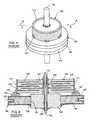
- FIGS. 1-6illustrate an exemplary prior art feedthrough filter capacitor 100 and its associated hermetic terminal 102 .
- the feedthrough filter capacitor 100comprises a unitized dielectric structure or ceramic-based monolith 104 having multiple capacitor-forming conductive electrode plates formed therein.
- Electrodesinclude a plurality of spaced-apart layers of first or “active” electrode plates 106 , and a plurality of spaced-apart layers of second or “ground” electrode plates 108 in stacked relation alternating or interleaved with the layers of “active” electrode plates 106 .
- the active electrode plates 106are conductively coupled to a surface metallization layer 110 lining a bore 112 extending axially through the feedthrough filter capacitor 100 .
- the ground electrode plates 108include outer perimeter edges which are exposed at the outer periphery of the capacitor 100 where they are electrically connected in parallel by a suitable conductive surface such as a surface metallization layer 114 .
- the outer edges of the active electrode plates 106terminate in spaced relation with the outer periphery of the capacitor body, whereby the active electrode plates are electrically isolated by the capacitor body 104 from the conductive layer 114 that is coupled to the ground electrode plates 108 .
- the ground electrode plates 108have inner edges which terminate in spaced relation with the terminal pin bore 112 , whereby the ground electrode plates are electrically isolated by the capacitor body 104 from a terminal pin 116 and the conductive layer 110 lining the bore 112 .
- the number of active and ground electrode plates 106 and 108together with the dielectric thickness or spacing therebetween, may vary in accordance with the desired capacitance value and voltage rating of the feedthrough filter capacitor 100 .
- the hermetic terminalincludes a ferrule 118 which comprises a generally ring-shaped structure formed from a suitable biocompatible conductive material, such as titanium or a titanium alloy, and is shaped to define a central aperture 120 and a ring-shaped, radially outwardly opening channel 122 for facilitated assembly with a test fixture (not shown) for hermetic seal testing, and also for facilitated assembly with the housing (also not shown) on an implantable medical device or the like.
- a ferrule 118which comprises a generally ring-shaped structure formed from a suitable biocompatible conductive material, such as titanium or a titanium alloy, and is shaped to define a central aperture 120 and a ring-shaped, radially outwardly opening channel 122 for facilitated assembly with a test fixture (not shown) for hermetic seal testing, and also for facilitated assembly with the housing (also not shown) on an implantable medical device or the like.
- An insulating structure 124is positioned within the central aperture 120 to prevent passage of fluid such as patient body fluids, through the feedthrough filter assembly during normal use implanted within the body of a patient. More specifically, the hermetic seal comprises an electrically insulating or dielectric structure 124 such as a gold-brazed alumina or fused glass type or ceramic-based insulator installed within the ferrule central aperture 120 .
- the insulating structure 124is positioned relative to an adjacent axial side of the feedthrough filter capacitor 100 and cooperates therewith to define a short axial gap 126 therebetween. This axial gap 126 forms a portion of a leak detection vent and facilitates leak detection.
- the insulating structure 124thus defines an inboard face presented in a direction axially toward the adjacent capacitor body 104 and an opposite outboard face presented in a direction axially away from the capacitor body.
- the insulating structure 124desirably forms a fluid-tight seal about the inner diameter surface of the conductive ferrule 118 , and also forms a fluid-tight seal about the terminal pin 116 thereby forming a hermetic seal suitable for human implant.
- Such fluid impermeable sealsare formed by inner and outer braze seals or the like 128 and 130 .
- the insulating structure 124thus prevents fluid migration or leakage through the ferrule 118 along any of the structural interfaces between components mounted within the ferrule, while electrically isolating the terminal pin 116 from the ferrule 118 .
- the feedthrough filter capacitor 100is mechanically and conductively attached to the conductive ferrule 118 by means of peripheral material 132 which conductively couple the outer metallization layer 114 to a surface of the ferrule 118 while maintaining an axial gap 126 between a facing surface of the capacitor body 104 , on the one hand, and surfaces of the insulating structure 124 and ferrule 118 , on the other.
- the axial gap 126must be small to preclude leakage of EMI.
- the outside diameter connection between the capacitor 100 and the hermetic terminal ferrule 118is accomplished typically using a high temperature conductive thermal-setting material such as a conductive polyimide. It will also be noted in FIG.
- peripheral support material 132is preferably discontinuous to reduce mechanical stress and also allow for passage of helium during hermetic seal testing of the complete assembly. In other words, there are substantial gaps between the supports 132 which allow for the passage of helium during a leak detection test.
- the coaxial capacitor 100permits passage of relatively low frequency electrical signals along the terminal pin 116 , while shielding and decoupling/attenuating undesired interference signals of typically high frequency to the conductive housing.
- Feedthrough capacitors of this general typeare available in unipolar (one), bipolar (two), tripolar (three), quadpolar (four), pentapolar (five), hexpolar (six) and additional lead configurations.
- the feedthrough capacitors(in both discoidal and rectangular configurations) of this general type are commonly employed in implantable cardiac pacemakers and defibrillators and the like, wherein the pacemaker housing is constructed from a biocompatible metal, such as titanium alloy which is electrically and mechanically coupled to the hermetic terminal pin assembly which in turn is electrically coupled to the feedthrough filter capacitor.
- the filter capacitor and terminal pin assemblyprevents entrance of interference signals to the interior of the pacemaker housing, wherein such interference signals could otherwise adversely affect the desired cardiac pacing or defibrillation function.
- Titanium oxide(or trioxide) is typical of the oxides that form on the surfaces of titanium. Titanium oxide is very rugged and very stable and in fact is often used as a pigment in paints due to its long-term stability. It is also an insulator or semiconductor.
- the attachment between the capacitor outside diameter metallization 114 and the titanium ferrule 118is accomplished using a thermalsetting conductive adhesive 132 , such as a conductive polyimide.
- a thermalsetting conductive adhesive 132such as a conductive polyimide.
- Ablestick Corporationmanufactures such polyimide compounds. If the oxide layer 134 builds up sufficiently in thickness, this can form an insulative surface which can preclude the proper operation of the feedthrough capacitor 100 as an effective electromagnetic interference filter.
- the capacitor ground electrode plates 108have a very low resistance and low impedance connection at RF frequencies. This is essential so that it can perform as a proper high frequency bypass element (transmission line) which will short out undesirable electromagnetic interference such as that caused by cellular telephones and other emitters.
- oxide layer 134If the oxide layer 134 is very thin, it creates only a few milliohms of extra resistance. However, recent measurements indicate that a thicker oxide layer can create resistance (measured at 10 MHz) ranging from 750 milliohms to over 30 ohms.
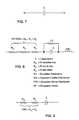
- FIG. 7is the schematic representation for an ideal capacitor C, which does not actually exist. In this regard, all capacitors have varying degrees of undesirable resistance and inductance. This is explained in more detail in “A Capacitor's Inductance,” Capacitor and Resistor Technology Symposium (CARTS-Europe), Lisbon, Portugal, Oct. 19-22, 1999, the contents of which are incorporated herein.
- FIG. 8is a simplified equivalent circuit model of the capacitor.
- the IRcan be ignored as it is in the millions of ohms and does not significantly contribute to the capacitor equivalent series resistance (ESR). IR also has negligible effect on capacitor high frequency performance.
- the inductance (ESL)can also be ignored because inductive reactance for monolithic ceramic capacitors is very low at low frequencies. Inductance for a feedthrough capacitor is very low and can be thought of as negligible at high frequencies. Accordingly, the capacitor ESR is the sum of the dielectric loss, the ohmic losses and any losses due to skin effect. However, at low frequency, skin effect is negligible.
- capacitor ESRis simply the sum of the capacitor's ohmic and dielectric losses.
- FIG. 10illustrates a normalized curve which shows the capacitor equivalent series resistance (ESR) on the Y axis versus frequency on the X axis.
- ESRcapacitor equivalent series resistance
- This curvehas been highly compressed into a U shape so that all of the important points can be illustrated on one graph.
- FIG. 10stretched out along its X axis by many times to get the true picture.
- the important point hereis the dielectric loss is also known as the dielectric loss tangent.
- the dielectric material that is used to build the monolithic ceramic capacitoris in itself capable of producing real loss (resistance) which varies with frequency.
- the dielectric resistanceis very high at low frequency and drops to zero at high frequency.
- This effectcan be thought of as oscillations in the crystal structure that produce heat or changes in electronic or electron spin orbits that also produce heat. No matter which dielectric model one uses, this dielectric loss can be very significant at low frequency.
- a capacitance value of around 4000 picofaradsis typical.
- Typical values of dielectric losswould be around 4000 ohms at 1 kHz, around 6 to 12 ohms at 1 MHz, and only a few milliohms at 10 MHz. This clearly indicates that as one goes up in frequency the dielectric loss tends to disappear.
- the dissipation factoris usually defined as a percentage, for example, 2.5% maximum. What this means is that the dielectric loss resistance can be no more than 2.5% of the capacitive reactance at a certain frequency (usually 1 kHz). For example, if the capacitive reactance for a particular capacitor was 80,000 ohms at 1 kHz with a 2% dissipation factor this would equate to 1600 ohms of resistance at 1 kHz.
- FIG. 10also illustrates that the dielectric loss essentially goes to zero at high frequency.
- FIG. 10also has superimposed on it another curve representing conductor ohmic loss which in a monolithic ceramic feedthrough capacitor is typically on the order of 0.25 ohms to 0.75 ohms. It should be pointed out that values of equivalent series resistance presented herein relate to only one illustrative example. In actual fact, the ESR of the capacitor varies with the capacitance value, the number of electrode plates, and the length and width of the electrode plates. Accordingly, a wide range of “normal” ESR readings can be obtained for many types of capacitors.
- a normal ESR readingmight be 0.05 ohms and for another design as much as 10 ohms. The important thing is that the ESR reading and the lot population represent oxide free connections that are very homogenous and the readings are stable across the lot population.
- the conductor ohmic lossescome from all of the feedthrough capacitor conductor materials and connections. That would include the lead wire or circuit trace itself, the electrical connection between the lead wire and the capacitor metallization, which might be solder or a thermalsetting conductive adhesive, the interface between the capacitor metallization and the internal electrode plates, the connection from the capacitor ground metallization to a ferrule, and the bulk resistance of the electrode plates themselves. Conductor ohmic loss does not vary with frequency until skin effect comes into play. Skin effect is also shown on FIG. 10 and one can see that the resistance starts to climb at the higher frequencies. For physically small MLC chips and feedthrough capacitors, skin effect does not really play a role until one gets to very high frequencies, for example, above 200 MHz.
- FIG. 11is a more detailed illustration of the dielectric loss shown by itself. At very low frequency the dielectric loss in ohms is quite high and as frequency increases, one can see that dielectric loss tends to go to zero. On this scale, the conductor ohmic losses, which are shown as metal loss, can hardly be detected (these are only a few milliohms in this case).
- titanium oxidecan vary in resistance from a few milliohms all the way up to 10 or even 30 ohms.
- a recently discovered problemis that when one makes measurements at 1 kHz it is impossible to see the effects of these oxides because they are hidden by the dielectric loss tangent, which can be as high as 4000 ohms or more by itself. Trying to find a resistance that has increased from 0.25 ohms for a titanium surface that is free of oxide up to 2 ohms is literally impossible in the presence of 4000 ohms of dielectric loss. The reason for this is that the dielectric loss can vary slightly from part to part (typically plus or minus 20 percent).
- the part to part variation at 1 kHzcan be as much as 100 ohms due to dielectric loss tangent variation alone. Therefore, it becomes quite impossible to detect the presence of this undesirable oxide layer on the titanium surface.
- the recently introduced Agilent equipmentis capable of making dielectric equivalent series resistance measurements at 10 MHz and above. This is a high enough frequency to get rid of the dielectric loss so that one can see the ohmic loss by itself (without being hidden under the dielectric loss).
- FIG. 12is a sweep from the Agilent E4991A RF Impedance—Materials Analyzer. Curve 136 illustrates the capacitor equivalent series resistance vs. frequency. The presence of these oxides can reduce EMI filter performance by as much as 20 dB. Stated another way, this could reduce EMI filtering effectiveness by a ratio of 10 to 1 or more. This is highly undesirable in an implantable medical device given the previous documented clinical interactions between cellular telephones and pacemakers. For example, it has been shown that cellular telephone interference can completely inhibit a pacemaker or cause it to go into asynchronous tracking or other undesirable behavior. This can be very dangerous even life threatening for a pacemaker-dependent patient. Further compounding this concern is the recent introduction throughout the marketplace of cellular telephone amplifiers.
- FIG. 13is the same as the sweep in FIG. 12 except this is taken from a part that has a substantial amount of undesirable titanium oxide build-up.
- Curve 136illustrates that at marker ( 2 ) there is 23.2529 ohms of resistance present.
- FIG. 13clearly illustrates that there is enough titanium oxide build-up to create 23.2529 ohms of series resistance at 10 MHz (a normal reading is 0.234 ohms for this particular capacitor). This is highly undesirable because it will preclude the proper operation of an EMI filter at this frequency and frequencies above.
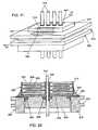
- FIGS. 14-19illustrate a prior art rectangular bipolar feedthrough capacitor (planar array) 200 mounted to the hermetic terminal 202 of a cardiac pacemaker in accordance with U.S. Pat. No. 5,333,095.
- Functionally equivalent parts shown in this embodiment relative to the structure of FIGS. 1-6will bear the same reference number, increased by 100.
- a ceramic feedthrough filter capacitor, 200is used in a feedthrough assembly to suppress and decouple undesired interference or noise transmission along one or more terminal pins 216 , and may comprise a capacitor having two sets of electrode plates 206 and 208 embedded in spaced relation within an insulative dielectric substrate or base 204 , formed typically as a ceramic monolithic structure.
- One set of the electrode plates 206is electrically connected at an inner diameter cylindrical surface of the capacitor structure 200 to the conductive terminal pins 216 utilized to pass the desired electrical signal or signals (see FIG. 16 ).
- the other or second set of electrode plates 208is coupled at an outer edge surface of the capacitor 200 to a rectangular ferrule 218 of conductive material (see FIG. 18 ).
- the number and dielectric thickness spacing of the electrode plate setsvaries in accordance with the capacitance value and the voltage rating of the capacitor 200 .
- the coaxial capacitor 200permits passage of relatively low frequency electrical signals along the terminal pins 216 , while shielding and decoupling/attenuating undesired interference signals of typically high frequency to the conductive housing.
- Feedthrough capacitors 200 of this general typeare available in unipolar (one), bipolar (two), tripolar (three), quadpolar (four), pentapolar (five), hexpolar (6) and additional lead configurations.
- Feedthrough capacitors 200(in both discoidal and rectangular configurations) of this general type are commonly employed in implantable cardiac pacemakers and defibrillators and the like, wherein the pacemaker housing is constructed from a biocompatible metal such as titanium alloy, which is electrically and mechanically coupled to the hermetic terminal pin assembly which is in turn electrically coupled to the coaxial feedthrough filter capacitor.
- the filter capacitor and terminal pin assemblyprevents entrance of interference signals to the interior of the pacemaker housing, wherein such interference signals could otherwise adversely affect the desired cardiac pacing or defibrillation function.
- FIG. 15illustrates an unfiltered hermetic terminal 202 typical of that used in medical implant applications.
- the ferrule 218is typically made of titanium or other biocompatible material.
- An alumina insulator 224 or other insulative material such as glass or the like,is used to electrically isolate the leads 216 from the conductive ferrule while at the same time providing a hermetic seal against body fluids.
- the lead wires or leads 216are installed into the insulating material 224 typically by gold brazing.
- a gold brazeis also formed between the alumina 224 and the ferrule 218 . In some applications, this can also be done with sealing glass so that the gold brazes are not required.
- the reference numbers 228 and 230on the one hand, and 228 ′ and 230 ′, on the other (FIG. 19 ), show gold brazes in two alternate locations that are used to form the hermetic seal between the titanium ferrule 218 and the alumina insulator 224 .
- FIG. 18illustrates the capacitor 200 mounted to the hermetic terminal 202 of FIG. 15 .
- the attachment 232 between the capacitor ground metallization 214 and the titanium ferrule 218is typically done with a conductive thermalsetting polymer, such as conductive polyimide or the like. It is also required that an electrical/mechanical connection be made between the capacitor inside diameter holes 212 and the four lead wires 216 . This is shown at 244 and can be accomplished with a thermalsetting conductive adhesive, solder, welding, brazing or the like.
- FIG. 19is a cross-sectional view of the capacitor assembly of FIG. 18, which is typical of prior art capacitors shown in U.S. Pat. No. 5,333,095 and related patents.
- the undesirable oxide layer 234can actually coat all surfaces of the titanium ferrule (for simplicity, it is only shown on FIG. 19 in the area where the conductive polyimide attachment 232 is made to the capacitor ground termination 214 ).
- the thermalsetting conductive material 232connects between the capacitor ground metallization 214 and the ferrule 218 .
- thiscan preclude the proper operation of the feedthrough capacitor 200 as previously mentioned.
- the presence of oxides of titaniumcan preclude the proper performance of monolithic ceramic EMI feedthrough filters.
- the titanium oxides that form during manufacturing processes or handlingform a resistive layer, which shows up at high frequency.
- High frequency impedance analyzer plots of resistance vs frequencyillustrate that this effect is particularly prominent above 10 MHz.
- the present inventionresides in an EMI feedthrough filter terminal assembly.
- the EMI feedthrough filter terminal assemblycomprises a feedthrough filter capacitor, a conductive ferrule adjacent to the feedthrough filter capacitor, at least one conductive terminal pin and at least one conductive ground lead.
- the feedthrough filter capacitorhas first and second sets of electrode plates, a first passageway therethrough having a first termination surface conductively coupling the first set of electrode plates, a second passageway therethrough having a second termination surface conductively coupling the second set of electrode plates, and a third termination surface exteriorly conductively coupling the second set of electrode plates.
- the conductive ferruleincludes an oxide resistant biostable conductive pad on a surface thereof which is conductively coupled to the third termination surface.
- the conductive terminal pinextends through the first passageway in conductive relation with the first set of electrode plates, and through the ferrule in non-conductive relation.
- the conductive ground leadextends through the second passageway in conductive relation with the second set of electrode plates.
- the ground leadmay extend through the ferrule in conductive relation.
- Meansare also provided for hermetically sealing passage of the terminal pin through the ferrule.
- meansare provided for hermetically sealing passage of the ground lead through the ferrule.
- an insulatoris fixed to the ferrule for supporting the terminal pin in conductive isolation from the ferrule.
- the ground lead, the ferrule and the insulatorcomprise a pre-fabricated hermetic terminal pin sub-assembly.
- the hermetic seal between the insulator and the ferruleis comprised of an oxide resistant biostable material.
- the hermetic sealalso forms the conductive pad on the surface of the ferrule.
- a conductive connectorextends between the third termination surface and the conductive pad.
- the conductive padcomprises a noble metal taken from the group consisting of gold, platinum, and oxide resistant alloys thereof.
- the conductive connectoris taken from the group consisting of conductive polyimide or solder.
- the third termination surfacemay comprise a plurality of third termination surfaces.
- the ferruleincludes a corresponding plurality of conductive pads which are conductively coupled to the plurality of third termination surfaces.
- the first passageway through the feedthrough filter capacitormay comprise a plurality of first passageways each having a distinct first termination surface conductively coupled to a distinct first set of electrode plates.
- the at least one terminal pincomprises a terminal pin extending through each of the plurality of first passageways.
- An insulative washeris disposed between the feedthrough filter capacitor and the conductive ferrule.
- the insulative washercomprises a thermal plastic polyimide supported tape, such as Ableloc.
- the terminal assembly shown hereinis specifically constructed for medical implant applications.
- medical implant applicationsinclude cardiac pacemakers, implantable cardioverter defibrillators, cochlear implants, neuro-stimulators, internal drug pumps, bone growth stimulators, artificial organs, artificial hearts, hearing assist stimulators, artificial limbs, artificial eyes, muscle actuators, and deep brain stimulators for seizure control, pain management and gene therapy.
- FIG. 1is a top and side perspective view of a typical unipolar ceramic discoidal feedthrough capacitor
- FIG. 2is an enlarged sectional view taken generally along the line 2 — 2 of FIG. 1;
- FIG. 3is a horizontal section taken along the line 3 — 3 of FIG. 2, illustrating the configuration of the ground electrode plates within the capacitor;
- FIG. 4is a horizontal section taken generally along the line 4 — 4 of FIG. 2, illustrating the configuration of the active electrode plates within the capacitor;
- FIG. 5is a perspective view of the capacitor of FIGS. 1-4, mounted to a typical hermetic terminal;
- FIG. 6is an enlarged sectional view taken generally along the line 6 — 6 of FIG. 5;
- FIG. 7is a schematic representation of an ideal capacitor
- FIG. 8is a simplified equivalent circuit model for a real capacitor
- FIG. 9is a schematic illustrating a low frequency model for capacitor ESR
- FIG. 10is a graph illustrating normalized curves which show the capacitor equivalent series resistance (ESR) on the y axis, versus frequency on the x axis;
- FIG. 11is a graph illustrating dielectric loss versus frequency
- FIG. 12is a graph illustrating capacitor equivalent series resistance versus frequency as illustrated in a sweep from an Agilent E4991A materials analyzer
- FIG. 13is a graph similar to that shown in FIG. 12, illustrating the resistance in a feedthrough filter capacitor assembly when a substantial amount of titanium oxide is present on the ferrule;
- FIG. 14is a perspective view of a rectangular broadband or low pass EMI filter capacitor
- FIG. 15is a perspective view of a prior art unfiltered hermetic terminal typical of that used in medical applications
- FIG. 16is a horizontal section taken generally along the line 16 — 16 of FIG. 14, illustrating the configuration of active electrode plates within the capacitor;
- FIG. 17is a horizontal section taken generally along the lines 17 — 17 of FIG. 14, illustrating the configuration of a set of ground electrode plates within the capacitor;
- FIG. 18illustrates the capacitor of FIG. 14 mounted to the hermetic terminal of FIG. 15;
- FIG. 19is an enlarged sectional view taken generally along the line 19 — 19 of FIG. 18;
- FIG. 20is a hermetic terminal similar to that illustrated in FIG. 15, but modified in accordance with features of the present invention.
- FIG. 21is a perspective view similar to FIG. 18, illustrating a rectangular feedthrough capacitor mounted to the hermetic terminal of FIG. 20;
- FIG. 22is an enlarged sectional view taken generally along the line 22 - 22 of FIG. 21;
- FIG. 23is a perspective view of a surface mount round quadpolar feedthrough capacitor embodying the present invention.
- FIG. 24is an enlarged sectional view taken generally along the line 24 — 24 of FIG. 23;
- FIG. 25is a chart illustrating the mechanical properties of thermoplastic polyimide supported tape adhesive
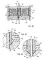
- FIG. 26is a sectional view similar to FIG. 24, illustrating a prior art feedthrough filter capacitor terminal typical of that shown in U.S. Pat. No. 4,424,551;
- FIG. 27is a sectional view similar to FIGS. 24 and 26, illustrating an alternative embodiment of a prior art feedthrough filter capacitor terminal
- FIG. 28is a sectional view similar to FIGS. 26 and 27, and further illustrating application of the present invention.
- FIG. 29is an enlarged view of the area indicated by the number 29 in FIG. 28;
- FIG. 30is an enlarged view of the area indicated by the number 30 in FIG. 28;
- FIG. 31is a perspective view of an internally grounded bipolar rectangular feedthrough capacitor as illustrated and described in U.S. Pat. No. 5,905,627;
- FIG. 32is a perspective view of a hermetic terminal suitable for use with the internally grounded feedthrough capacitor of FIG. 31;
- FIG. 33is a sectional view through the capacitor of FIG. 31, illustrating the active electrode plates
- FIG. 34is a sectional view similar to FIG. 33, illustrating the configuration of the ground electrode plates
- FIG. 35is a perspective view of the internally grounded bipolar feedthrough capacitor of FIG. 31 mounted to the hermetic feedthrough terminal of FIG. 32;
- FIG. 36is a cross-sectional view taken generally along the line 36 — 36 of FIG. 35;
- FIG. 37is a perspective view of a hybrid capacitor which has the characteristics of a conventional surface-mounted feedthrough capacitor and an internally grounded capacitor;
- FIG. 38is a horizontal section through the capacitor of FIG. 37, illustrating the configuration of the ground electrode plates therein;
- FIG. 39is a horizontal section similar to FIG. 38, illustrating the configuration of the active electrode plates therein;
- FIG. 40is a perspective view of an hermetic terminal designed for use in connection with the capacitor illustrated in FIGS. 37-39, the terminal including a titanium ferrule;
- FIG. 41is a top plan view of the capacitor of FIG. 37 mounted to the hermetic terminal of FIG. 40;
- FIG. 42is a sectional view taken generally along line 42 — 42 of FIG. 41;
- FIG. 43is a sectional view similar to FIG. 42, illustrating a hybrid capacitor which has a centered ground pin and which is also grounded at its right and left ends to gold bond pads;
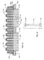
- FIG. 44is an enlarged, perspective and partially exploded view of one of the terminal pins shown in FIG. 43;
- FIG. 45is a sectional view similar to FIG. 43, illustrating an internally grounded hex polar capacitor and related hermetic terminal embodying the present invention
- FIG. 46is an enlarged perspective view of a terminal pin utilized in the structure of FIG. 45;
- FIGS. 47A-Care an enlarged fragmented and sectional views of the area indicated by the line 47 in FIG. 45, illustrating three different embodiments of attachment of the lead wire;
- FIG. 48is a sectional view similar to FIGS. 43 and 45, illustrating an externally grounded quadpolar device.
- FIG. 49is an enlarged fragmented view of the area 49 shown on FIG. 48 .
- Titanium housings, casings and ferrules for hermetic sealsare commonly used in the medical implant industry.
- Pacemakers, implantable defibrillators, cochlear implants and the likeall have ferrules or housings made of titanium or titanium-ceramic composite structures. All of the aforementioned devices are also subject to electromagnetic interference (EMI) from emitters that are commonly found in the patient environment. These include cell phones, microwave ovens and the like.
- EMIelectromagnetic interference
- the inventorshave noted that the presence of oxides of titanium can preclude the proper performance of monolithic ceramic EMI feedthrough filters.
- the titanium oxides that form during manufacturing processes or handlingform a resistive layer.
- High frequency impedance analyzer plots of resistance vs frequencyillustrate this effect is particularly prominent above 10 MHz.
- the novel invention as described hereindeposits an oxide resistant conductive coating on the surface of the titanium to provide a resistively stable area to which the ground electrode plates of the feedthrough capacitor can be reliably and consistently attached. Attachments between the capacitor ground electrode plates are typically performed in the prior art by a conductive termination layer which is a part of the feedthrough capacitor, wherein the termination layer connects the ground electrode plates in parallel.
- the termination material as described in the prior artprovides a convenient electrical and solderable connection to the capacitor ground electrode plates.
- the active electrode platesare similarly terminated at their inside diameter (feedthrough holes).
- the primary role of the EMI filter capacitoris to appear as a very low impedance at RF frequencies.
- the presence of resistance due to a titanium oxide in the capacitor connectionundesirably raises its overall impedance. Oxides of titanium are additionally problematic in that they are not stable with time and temperature (they can continue to build-up). These oxides can preclude the proper filtering function of the capacitor. For example, the presence of 23.25 ohm titanium oxide(s) resistance overwhelms the impedance of the feedthrough capacitor, which generally measures less than 600 milliohms at the HF frequency band. This means that the feedthrough capacitor is no longer an effective EMI filter.
- EMI filtersare placed at the point of lead ingress in implantable medical devices such as cardiac pacemakers, implantable defibrillators and the like, is to be sure that the implanted electronic device will continue to operate properly in the presence of electromagnetic fields.
- a notorious exampleis the microwave oven. It wasn't that many years ago that a number of serious interactions were documented between microwave ovens and cardiac pacemakers and warning signs appeared in stores and other places that were using such devices.
- the titanium housing that encompasses modern implantable deviceslargely precludes problems from microwave ovens along with effective EMI filters.
- Another notable exampleis the cellular telephone (and other hand held wireless communication devices).
- connection between the capacitor ground termination and the titanium ferruleis typically done using a thermalsetting conductive material such as a conductive polyimide material or the like.
- a thermalsetting conductive materialsuch as a conductive polyimide material or the like.
- titaniumis not solderable.
- conductive thermalsetting materials to make this connectionis well known in the art.
- novel conductive coating of the titanium ferrule of the hermetic seal as described hereinis accomplished in one of a variety of ways:
- a related inventionis also shown in the accompanying drawings. This is the unique capability of connecting directly between the lead wire and the gold braze. This is of great advantage for lead materials that form heavy oxide layers, are non-solderable, or both. For biomedical applications, this allows the use of titanium, niobium, tantalum and other lead materials which are much less expensive than the current platinum or platinum-iridium leads.
- FIG. 20illustrates a hermetic terminal 302 which is similar to the hermetic terminal 202 of FIG. 15, but which has been modified in accordance with the present invention by extending a gold braze area 346 to create a rectangular pad as shown.
- the gold braze 346which runs around the alumina insulator 324 , is also run into two pockets that are convenient for capacitor mounting.
- FIG. 21shows a quadpolar feedthrough capacitor 300 (which is identical to the capacitor 200 of FIG. 14) mounted to the hermetic terminal of FIG. 20 .
- the conductive polyimide material 332now connects between the capacitor metallization 314 and the gold braze area 346 .
- the gold brazeforms a metallurgical bond with the titanium and precludes any possibility of an oxide forming.
- Goldis a noble metal that does not oxidize and remains very stable even at elevated temperatures.
- the novel construction methodology illustrated in FIG. 21guarantees that the capacitor ohmic losses will remain very small at all frequencies.
- FIG. 22is a cross-section of the capacitor shown in FIG. 21 .
- the gold braze (or weld) areas 328 and 330 that form the hermetic seal between the alumina insulator 324 and the titanium ferrule 318are desirably on the feedthrough capacitor side. This makes it easy to manufacture the gold bond pad area 346 for convenient attachment of the conductive thermalsetting material 332 . In other words, by having the gold braze hermetic seals on the same side as the gold bond pad area, these can be co-formed in one manufacturing operation in a gold braze vacuum furnace. Further, a unique thermalsetting material 348 is disposed between the capacitor 300 and the underlying hermetic terminal 302 .
- Another feature of the present inventionis that in the prior art only conductive thermalsetting materials could be used to electrically connect the capacitor ground metallization 314 to the ferrule 318 . This is because titanium, niobium, tantalum and other biocompatible materials used for human implant ferrules are generally not solderable. With the present invention, it is now possible to replace the thermalsetting conductive adhesive with solder. Solder paste could also be used. This is because solder will properly wet and bond to the gold braze area 346 . Solder reflow operations tend to be more cost efficient (more automatable) as compared to dispensing of thermalsetting conductive adhesives. It should also be noted that the gold bond pad area 346 of FIG. 21 could be achieved using other methods.
- Gold brazingis one method that has already been described. However, sputter coatings of material surfaces such as gold, platinum or other conductive materials could be done. In addition, the gold bond pad area 346 could be done by electroplating of a suitable material that would form an electrical bond to the titanium and preclude oxide formation or by any other deposition method capable of achieving the desired result.
- a novel feature of the present inventionis the capability of producing a hermetic seal using noble materials such as gold braze while at the same time forming a gold bond pad or landing area to which to connect the capacitor ground metallization.
- the hermetic seal 330forms a hermetic braze connection between the ferrule 302 and the alumina insulator 324 .
- Thisalso, at the same time, forms the gold bond pad 346 for convenient connection of the conductive polyimide 332 .
- the conductive polyimideforms the electrical connection between the capacitor ground electrode plates through the capacitor metallization 314 which connects directly to the conductive polyimide 332 and to gold bond pad 346 .
- hermetic connection 330be co-formed with gold bond pad 346 .
- a single gold pre-formcan be used, which is formed to accommodate the area as shown.
- thiscan all be done in one batch of product put into the vacuum gold brazing furnace at one time.
- batches of partsare placed into carbon/graphite holding/alignment fixtures called boats, the lead wires and alumina and gold pre-forms along with the ferrules are then all loaded into this special fixture. The operator then places these in a sealed chamber known as a vacuum brazing furnace.
- the temperatureis raised sufficiently to re-flow the gold braze material.
- the goldmakes a connection between sputtering, which was formerly placed on the alumina terminal 324 so that good wetting takes place, and a hermetic seal is formed. There is also a good wetting to the titanium such that a hermetic seal is formed there also.
- Thiscan all be done in one continuous operation wherein the gold only wets to the titanium in the selected areas where the conductive polyimide 332 is to be placed. Accordingly, the structure as shown in 332 in FIG. 22 can all be formed in one manufacturing step with very little added cost. There is also an electrical advantage to doing it this way.
- FIG. 1 of the Wolf patentdiscloses a gold braze 40 for connection of the conductive polyimide 47 to the titanium ferrule.
- Wolfindicates that the insertion loss or high frequency performance of the EMI filter is improved by connection to this gold bond pad.
- FIG. 9illustrates the attenuation in decibels with and without a gold bond pad 40 .
- the hermetic sealis made between the alumina insulator using a gold braze shown in FIG. 1 as Item 15 .
- the gold braze 15connects between the ferrule 93 and the alumina insulator 25 .
- any material used to make electrical connection between the ceramic capacitor and the ferruleis described as a conductive thermalsetting material, such as a silver filled polyimide or a solder or the like. None of these are suitable biocompatible sealing materials for human implant applications and they certainly do not make a hermetic seal (nor does solder since it is not considered a biocompatible material).
- FIG. 23illustrates a surface mounted quadpolar feedthrough capacitor 400 .
- a gold braze bond pad area 446has been added to facilitate the connection between the capacitor outside diameter metallization 414 and the titanium ferrule 418 . As mentioned before, this connection can be made as in the past with a thermalsetting conductive adhesive 432 or with solder or the like.
- FIG. 24is a cross-section of the quadpolar feedthrough filter capacitor terminal of FIG. 23 .
- the gold braze area 446 or optionally 446 ′has been extended and widened so that the capacitor outside diameter electrical connection 432 will touch off between the capacitor outside diameter metallization 414 and the gold braze surfaces 446 or 446 ′.
- FIG. 24Another inventive concept illustrated in FIG. 24 is the electrical connection 444 between the lead wires 416 and the capacitor metallization 410 and gold braze 428 , 428 ′. This has been made possible by use of a thermalsetting insulative material 448 .
- a unique design constraint affecting filtered hermetic terminals for implantable medical devicesis that these devices are designed to be welded into the overall titanium housing of a pacemaker, implantable defibrillator or the like. Accordingly, the feedthrough capacitor assembly is subjected to a great deal of heat and thermal stress.
- the insulative material 448has to withstand very high temperature.
- One such insulative material 448is a unique thermal plastic polyimide supportive tape (coated with thermalsetting adhesive) manufactured by Ablestik Electronic Materials and Adhesives, (the mechanical properties of which are listed in FIG. 25.) This material, which is known as Ableloc 5500, is unique in that it has the high temperature characteristics of a polyimide and yet will not flow. In other words, it stays in place, which allows one to form the novel structure shown at 448 .
- the bottom or the surface between the capacitor 400 and the alumina insulator 424be sealed so that conductive materials or fluids cannot run between the capacitor pins and short it out.
- the Ableloc 5500is ideal in that it forms a seal while remaining in place. This means that for the first time the present invention can guarantee that the capacitor inside diameter connection can be between the capacitor metallization 410 and the gold braze 428 or 428 ′, which opens up entirely new possibilities.
- niobium or tantalum pinscan be utilized, without preparatory and secondary processing operations which are required because these materials are notoriously covered with oxide. No longer must there be a direct connection between the capacitor metallization 410 and the pin 416 itself.
- the gold braze 428 or 428 ′which forms the hermetic seal, makes an oxide free metallurgical and very low resistance connection to the pin itself (in a one step operation). Accordingly, the electrical connection 444 between the pin 416 as shown in FIG. 24 is actually from the capacitor inside diameter metallization 410 directly to the gold braze 428 . The presence of oxides on the pin simply doesn't matter since a very low resistance electrical connection has already been formed. This electrical connection is also RF tight allowing the feedthrough capacitor to operate at very high frequency as a proper EMI filter.
- FIG. 26represents a prior art feedthrough capacitor 500 typical of U.S. Pat. No. 4,424,551 and related patents.
- the bottom surface of the capacitor 500has been flooded with a nonconductive epoxy 550 .
- the insulative material 550is cured so that the capacitor 500 is bonded into the case 518 .
- the entire surface above the capacitor 500is flooded with conductive polyimide material 532 , which is then centrifuged into place. It is very important during the centrifuge operation that material not flow underneath the capacitor thereby forming a short between the ferrule and the capacitor inside diameter pin 516 .
- An optional insulative epoxy coating 552could be added to cosmetically cover the surface of the capacitor 500 and offer it some degree of mechanical protection.
- This prior art assemblythere is no way for the conductive polyimide 544 at the inside diameter to reach the gold braze 528 . Also, it is not possible for the outside diameter conductive polyimide 532 to reach the gold braze 530 . This type of prior art assembly is sensitive to any type of titanium oxide build-up that may occur on the inside diameter of the titanium ferrule.
- FIG. 27illustrates another prior art feedthrough capacitor 600 and related structure.
- This unithas a substantial oxide layer 634 on the inside of the titanium ferrule 618 .
- this oxide layeris only shown on the inside diameter of the ferrule 618 where the electrical connection to the capacitor ground metallization 614 is made (in actual practice, the oxide would to some degree coat all of the ferrule surfaces). Accordingly, there will be a high resistance between the conductive polyimide 632 and the titanium ferrule 618 .
- the gold brazes 628 and 630are shown on the opposite side away from the feedthrough capacitor 600 . Accordingly, there is no way in this structure for the feedthrough capacitor ground polyimide connection to have contact with the gold braze 630 .
- this prior art assemblyis subject to EMI filter performance degradation if the oxide layer becomes too thick. Product life is another concern. Oxides can build up very slowly over time and lead to a latent type of design defect.
- FIG. 28illustrates the novel technology of the present invention as applied to the basic structures illustrated in FIGS. 26 and 27.
- the unique Ableloc 5500 or equivalent high temperature thermal plastic polyimide supportive tape 748allows the nonconductive insulating material to be held in place as shown (B staged epoxy washers could also be used, however, their temperature rating is not as high). This allows clear access for the conductive polyimide 744 or 732 to penetrate and contact the gold braze area 746 . In this case, it is important that the gold braze be on the capacitor side of the insulator 724 .
- the assembly shown in FIG. 28no longer requires that the pin(s) 716 be restricted solely to platinum iridium or other non-oxidizing materials.
- the electrical connectioncan be between the capacitor inside diameter metallization 710 directly to the gold braze 728 itself. Accordingly, there is no need for an electrical connection between the capacitor inside diameter metallization 710 and the lead wire 716 at all. It can also be clearly seen in FIG. 28 that it would not matter if the inside diameter of the ferrule 718 was heavily oxidized. This is because there is an electrical connection directly from the capacitor outside diameter metallization 714 to the outside diameter gold braze 730 .
- FIG. 29is a broken out enlarged view of the outside diameter connection of FIG. 28 .
- there is an oxide layer 734which would tend to insulate the conductive polyimide or solder 732 from the titanium.
- the conductive polyimide, solder or the like 732can make direct contact between the capacitor metallization 714 and the gold braze area 730 .
- Sputtering 754 of metals on the alumina insulator 724are required before the gold braze hermetic seal typically can be formed. This allows the gold braze material 730 to wet to the alumina insulator 724 and form a hermetic seal.
- FIG. 30is an enlarged view of the electrical connection to the lead wire 716 of FIG. 28 .
- a type of lead wiresuch as tantalum or niobium, which would be heavily oxidized 734 .
- these oxidesare highly insulative, but they also do not form a solderable surface.
- a feature of the inventionis that during hermetic seal construction, the oxides are absorbed by the metallurgical bond formed between the gold braze area 728 and the pin 716 . This is the same gold braze that forms the hermetic seal to the alumina insulator 724 .
- a sputtered layer 754allows the gold to wet to the insulator 724 .
- the connection to the capacitoris accomplished by the thermalsetting conductive adhesive or solder 744 which connects from the capacitor metallization 710 directly to the gold braze 728 . Since the gold braze 728 has a metallurgical low resistance and low impedance connection to the pin, no further connection is required.
- a non-oxidizing pin materialsuch as platinum, gold or platinum-iridium alloy, it is not necessary to form the structure as illustrated in FIG. 30 . In other words, the insulative washer 748 could extend all the way across the inside diameter thereby blocking access to the gold braze.
- the most critical element in a medical implant feedthrough design(that must remain hermetic throughout it's device service life) is the metal/ceramic interface. Important are the nature of the bond itself and the sensitivity of the bond integrity to environmental conditions imposed as a result of the device fabrication process (like installation by laser welding by the pacemaker manufacturer) or as a part of environmental conditions developed while in service (body fluid is highly corrosive).
- the bondFor a braze-bonded feedthrough, the bond needs to deform in a ductile manner when environmental conditions create stresses (e.g., heating and cooling cycles that develop during device assembly welding).
- metallization and braze material combinationsdevelop alloys that solidify as intermetallics. These intermetallics often show only modest ductility prior to failure. If material combinations are not judiciously selected and processes are not understood and controlled, significant dissolution can occur, and brittle fracture of the bond, or latent failures (static fatigue) result compromising hermetic integrity of the feedthrough.
- a unique challenge for formation of the novel bond pads of the present inventionis that they are formed as an integral part of the hermetic seal joint. This requires a relatively large amount of gold braze material (or other noble metal) to be used. In prior art EMI filtered human implant hermetic seals, the volume of braze material is by design relatively small. In the present invention, with the larger volume of braze material that is required, higher stresses due to shrinkage and mismatches in the thermal coefficient of expansion (TCE) of the braze material become a major design challenge.
- TCEthermal coefficient of expansion
- the biggest concernis the added stress in tension or shear which is transmitted to the metallic layer on the alumina hermetic seal/insulator (this layer is what allows the braze material to wet to the alumina and form the hermetic seal and is preferably applied by sputtering or equivalent methods).
- this layeris what allows the braze material to wet to the alumina and form the hermetic seal and is preferably applied by sputtering or equivalent methods.
- the TCE of the high alumina content ceramic insulatordoes not match the TCE of any of the noble metal braze materials.
- a unique metallizationis required to be used in combination with the present invention that has high malleability and very high adhesion strength to the alumina ceramic and will also wet well to the braze material.
- the preferred metallization on high alumina ceramics for miniature medical implantable device hermetic terminalsis titanium/molybdenum. Titanium is the active layer, and molybdenum is the barrier layer controlling how much titanium can actually dissolve in the gold. For example, 2-4 microns of titanium can be sputtered followed by 2-4 microns of molybdenum. The thickness will be dependent on the design, the application, and the subsequent potential environmental exposures.
- the titanium layerprovides the interaction with the glass phases and alumina particle matrix of the ceramic to create a hermetic bond.
- the molybdenum layerprotects the titanium layer from excessive oxidation prior to brazing and acts as a barrier between the gold braze material and the titanium layer. Without the molybdenum barrier layer, an excessive length of exposure of the titanium layer to the molten gold would accelerate the inherent alloying process and eventually lead to de-wetting, then hermetic failure
- the titanium/molybdenum metallization in concert with gold brazetherefore, not only provides a sound hermetic bond, but also provides a sufficiently ductile materials feedthrough system to sustain secondary device assembly processes or environmental conditions that might develop stresses while the device is in service.
- Sputteringis one metallization application method.
- Other methods that might be usedinclude but are not limited to chemical vapor deposition, laser or other physical vapor deposition processes, vacuum evaporation, thick film application methods, plating, and so on.
- FIGS. 31-36illustrate an internally grounded bipolar rectangular feedthrough capacitor 800 as described in U.S. Pat. No. 5,905,627.
- the center holeis the grounded hole 858 which would connect to the capacitor internal electrode plates 808 .
- the feedthrough filter capacitor 800comprises a monolithic, ceramic internally grounded bipolar feedthrough filter capacitor having three passageways extending therethrough.
- the outer two passageways 856are configured to receive therethrough respective conductive terminal pins 816 ′ and 816 ′′, and the internal diameter of the first passageways 856 are metallized 810 to form a conductive link between the active electrode plates 806 .
- the active electrode plates 806are typically silk-screened onto ceramic plates forming the feedthrough filter capacitor 800 . These plates 806 are surrounded by an insulative ceramic material 804 that need not be metallized on its exterior surfaces.
- ground electrode plates 808are provided within the feedthrough filter capacitor 800 .
- the inner diameter of the central or second passageway 858 through the feedthrough filter capacitor 800is also metallized 811 to conductively connect the ground electrode plates 808 , which comprise the ground plane of the feedthrough filter capacitor 800 .
- the second passageway 858is configured to receive therethrough the ground lead 860 which, in this particular embodiment, comprises a ground pin.
- the terminal pin subassemblycomprises a plate-like conductive ferrule 818 having three apertures therethrough that correspond to the three passageways through the feedthrough filter capacitor 800 .
- the conductive terminal pins 816 ′ and 816 ′′are each supported through the outer apertures by means of an insulator 824 (which also may be hermetic), and the ground pin 860 is supported within the central aperture by a suitable conductor 830 such as gold brazing, solder, an electrically conductive thermalsetting material or welding/brazing.
- the feedthrough filter capacitor 800is placed adjacent to the non-body fluid side of the conductive ferrule 818 and a conductive attachment is effected between the metallized inner diameter of the first and second passageways 856 and 858 through the feedthrough filter capacitor 800 and the respective terminal pins 816 and ground lead 860 .
- the capacitor 800could be placed adjacent to the body fluid side of the conductive ferrule 818 provided the capacitor comprises a design incorporating biocompatible materials.
- the conductive connections 844 between the terminal pins 816 and the ground lead 860 , with the feedthrough filter capacitor 800may be effected by any suitable means such as a solder or an electrically conductive thermalsetting material or brazing. The result is the feedthrough filter capacitor assembly illustrated in FIGS. 35 and 36 which may then be subsequently laser welded into the titanium housing of an implantable medical device.
- FIG. 35illustrates the internally grounded bipolar feedthrough capacitor 800 of FIG. 31 mounted to the hermetic feedthrough terminal 802 of FIG. 32 .
- the ground lead 860can be shortened so that it does not protrude through the capacitor 800 or it can be lengthened depending on whether or not a circuit attachment is required within the implantable medical or other electronic device. If the lead wires are solderable (platinum or gold), then the connection between the lead wires and the capacitor inside diameter metallization can be accomplished using solder, conductive adhesive or the like.
- a feature of the internally grounded feedthrough capacitor 800is that no outside diameter (or perimeter in the case of FIG. 35) electrical connection or capacitor metallization is required.
- FIG. 36is a cross-section of the capacitor assembly of FIG. 35 .
- lead wire materials that are subject to oxidationsuch as niobium or tantalum.
- the thermal plastic polyimide supportive tape 850has been carefully punched, die-cut, or laser cut to align with the capacitor such that the capacitor feedthrough holes are open to the gold braze material 830 underneath. This allows a direct connection of the solder or conductive polyimide 844 to connect directly between the capacitor metallization 810 , 811 and gold braze material 830 .
- thisopens up a wide variety of lead materials for use, which could not be considered before due to their heavy oxidation or poor solderability properties.
- Thisalso allows the use of a ground pin of alternate materials, like titanium.
- a titanium ground pinis desirable because it is very easy to weld a titanium pin into a titanium ferrule.
- a feature of the present inventionis the capability of connection to the gold braze area. It should be apparent that not all leads are required to be constructed of the same material.
- the center (ground) lead 860could be titanium and the two active pins 816 ′ and 816 ′′ could be platinum. In this case, it would not be required that conductive material 844 adjacent the platinum pins 816 ′ and 816 ′′ contact the gold braze 830 .
- FIG. 37illustrates a novel hybrid capacitor 900 which has the characteristics of a conventional surface mounted feedthrough capacitor and an internally grounded capacitor.
- This capacitor 900has a ground hole 958 in the center which connects to the internal ground electrode plates 908 and also has ground terminations 914 at either end. The reason for this is that this capacitor has a form factor which tends to increase its inductance and impedance. Accordingly, if one were to only make connection to the ground electrodes 908 shown in FIG. 38 at the center hole 958 , there would be too much inductance between this and the outer pins to perform effective EMI filtering.
- This hybrid designis best illustrated by the ground electrode plate pattern as shown in FIG.
- FIG. 39is an illustration of the active electrode plate pattern 906 .
- FIG. 40illustrates the simplified hermetic terminal 902 .
- the centered ground pin 960is welded or brazed 928 directly to the ferrule 918 . This forms a low resistance and low inductance ground connection to the pin 960 .
- the other pins 916are shown in insulative relationship with the ferrule 918 .
- the novel gold bond pads of the present inventionare shown as 946 . Restated, the ground pin 960 has been solidly brazed directly to the ferrule 918 . This provides a very low impedance RF ground between the center pin 960 and the overall electromagnetic shield.
- FIG. 40illustrates the simplified hermetic terminal 902 .
- the centered ground pin 960is welded or brazed 928 directly to the ferrule 918 . This forms a low resistance and low inductance ground connection to the pin 960 .
- the other pins 916are shown in insulative relationship with the ferrule 918 .
- the novel gold bond pads of the present invention
- the gold bond pads 946have been added on either end to form a convenient surface for the electrical connection between the capacitor end terminations 914 and the ferrule 918 . It can also be seen that the other four pins 916 on both the right and left sides of the capacitor 900 are in electrically insulative relationship. This is done through the insulators 924 which can be glass or a gold brazed alumina seal.
- FIG. 41is a top view of the capacitor of FIG. 37 mounted to titanium ferrule 918 .
- the novel gold braze ground pads 946 of the present inventionhave been added so that an oxide free electrical connection can be made between the capacitor-ground terminations 914 and the conductive ferrule 918 .
- FIG. 42is a cross-sectional view of the capacitor 900 assembled to the hermetic terminal 902 of FIG. 40 .
- the gold bond pads 946are also part of a single monolithic structure forming the hermetic seal between the ferrule 918 and the insulator 924 , in the same manner and for the same reasons as discussed above in connection with FIG. 22 .
- the connection between the capacitor ground metallization 914 (at its two ends) and the gold bond pads 946is shown as material 932 , which can be solder, conductive thermalsetting material, or the like.
- the connection to the centered ground pin 960is illustrated by material 944 which can also be solder, conductive thermalsetting material, or the like.
- insulative material 948such that the electrical connecting material 944 adjacent to the ground pin 960 will directly contact the gold braze 928 . This is particularly important for ground pin lead materials that are not readily solderable or that form insulative oxide layers.
- the novel gold bond pad area 946 as previously mentionedcould also be accomplished by sputtering, plating and the like.
- the hermetic terminal 902includes two distinctly different sets of lead wires 916 .
- the lead wires 916are shown as comprised of low cost niobium or tantalum pins on which heavy oxides typically form.
- the pads of oxide resistant conductive biostable material, noble metal, or the like, 946are utilized to provide both a hermetic seal between the pins and the insulator 924 , and also to provide a reliable electrical connection between the interior termination surfaces 910 and the leads 916 , as discussed above in connection with FIGS. 24, 28 - 30 and 36 .
- the lead wires 916 to the right of the ground pin 960are all platinum.
- platinumis not subject to oxidation. Accordingly, it is not necessary for the solder or conductive polyimide used to connect between the capacitor inside diameter metallization and the lead wire to also contact the gold braze material 928 . In other words, an oxide free electrical connection has already been made between the capacitor inside diameter metallization 910 and the lead wire 916 , therefore it is not necessary to modify this assembly to contact the gold braze.
- the aforementioned polyimide supportive tape 948 or the likecould be placed to allow direct contact from the ground pin 960 to the gold braze 930 thereby allowing the use of a ground lead wire such as titanium, niobium or tantalum.
- FIG. 43shows a hybrid capacitor 1000 which has a centered ground pin 1060 and, because of its length and the desire to reduce inductance, is also grounded at its right and left ends using conductive polyimide 1032 to the gold bond pads 1046 .
- Thisis a hybrid in that it incorporates the features of both U.S. Pat. Nos. 5,333,905 and 5,095,627.
- FIG. 43illustrates novel wire bond pads that overcome all of the obvious deficiencies of the aforementioned Wolf patent.
- the preferred location for the hermetic braze between the insulators 1024 and the hermetic terminal 1002is at the pads 1046 . This takes the gold braze away from the body fluid both at each terminal pin and also at the hermetic seal joint to the ferrule.
- FIGS. 43 and 44further illustrate an extruded nail head lead 1016 of bio-compatible material such as a noble metal including platinum, platinum iridium, gold and the like.
- the nail head portion 1062 of the lead 1016 on the bottom or body fluid sidecould be extruded as one piece particularly with a malleable material welded in place, brazed in place, or adhesively secured in place to the lead 1016 .
- the capacitor 1000is attached to the terminal 1002 using similar processes as described above, and the leads 1016 are attached at the time that the hermetic seal joint 1046 is formed. During capacitor attachment the leads 1016 are allowed to stick through the capacitor 1000 as shown. At this point there are a number of options for the assembly.
- wire bond pad 1064does not need to be bio-compatible and could be made of a number of inexpensive materials including nickel, copper, steel and the like. For wire bond applications it is usually required that the wire bond pad 1064 be pure (soft) gold plated, but a number of other surface finishes can be applied as well.
- the wire bond pads/nail head assembly 1016 , 1064could also be formed from the group of metals including: tantalum, molybdenum, titanium, rhodium, titanium alloys, osmium, silver and silver alloys, vanadium, platinum, niobium, platinum alloys, stainless steel, tungsten, rhenium, zirconium, vanadium and ruthenium.
- FIG. 45illustrates an internally grounded hex polar capacitor 1100 embodying the invention (refer to U.S. Pat. No. 5,905,627).
- the novel wire bond pads 1164 as previously describedhave been utilized.
- the nail head pin 1116is of the same group of materials as previously described for FIG. 43 .
- the hermetic seal 1146has been moved to an alternate location and is now closer to exposure to body fluids. This is also acceptable to many customers but is not the preferred embodiment for maximum resistance to long term decomposition by metal migration.
- the wire bond pad 1164 on the inside of the implantable medical devicehas also been modified so it has an open hole.
- thisa ring structure which is slipped over the bio-compatible pin 1116 and then attached by soldering, welding, brazing, or thermalsetting conductive adhesive or the like.
- An advantage of this structureis it is a little bit easier to assemble and inspect.
- a disadvantageis that the area available for customer attachment of their lead wires by ultrasonic wire bonding, thermal sonic welding or direct welding has been reduced. In other words there is less flat surface area available for customer lead attach.
- the lead wire 1160extends through a toroidal ring 1164 ′ which may be constructed of various materials from the group of metals, and ceramics.
- a toroidal ring 1164 ′which may be constructed of various materials from the group of metals, and ceramics.
- One preferred embodimentwould be the use of alumina ceramic which was metallized. This would allow one to form the electrical connection shown while at the same time allowing the lead wire 1160 to protrude through.
- the very end of the lead wire 1160could be the wire bond pad itself.
- the preferred metallized alumina toroidal ring 1164 ′has been metallized on all surfaces so it is both solderable and conductive.
- Solder, thermalsetting conductive adhesive, welding or the like 1168performs an electrical connection between the circular torroid 1164 ′ which in turn connects to the capacitor 1100 active electrode plates 1106 .
- material 1170which can be of the group of solder, thermalsetting conductive adhesives, welding, brazes or the like, forms the electrical connection between the lead wire 1160 to the torroidal structure 1164 ′ which then couples through the electrical connection 1168 via the capacitor metallization 1110 to the electrode plates.
- the tip of the lead wire 1172is flat to accept lead attachment by the customer by wire bonding, thermal sonic bonding, laser welding or the like.
- a supplementary nail head or enlarged areacould be added to the tip 1172 to increase the surface area available for such customer lead attachment operations.
- One particular advantage of the structure shown in FIG. 47is the ability to select a material that closely matches a thermal co-efficient expansion of the ceramic capacitor 1100 . Such materials include fosterite, zirconium, gold alloys, or materials such dumet.
- Capacitor 1100has inside diameter metallization 1197 at each of the seven inside diameters to make electrical connection to the ground and active electrode plate sets. This metallization also appears on top of the capacitor as a circular mounting/bonding pad 1199 . In this case, there is no need to fill the space between the capacitor inside diameters and the noble metal lead wires with an electrical connection material.
- FIG. 47Bshows that the lead wire and its electrical connection may be subflush or below the top of the ring pad 1164 .
- the ring padforms the wire bond surface.
- the electrical connectionis formed between pin 1116 and the capacitor top metallization 1199 using solder, braze, conductive adhesive or the like.
- Alternative connections using a variety of wire bond pad end capsare shown in FIGS. 47A, 47 B, and 47 C.
- FIGS. 48 and 49show an externally grounded quadpolar device. While a compatible nail head pin 1216 is utilized and in this case, the hermetic seal connection 1246 between the alumina ceramic 1224 and the nail head pin 1216 is in the preferred location. Drawing attention now to the wire bond end cap 1264 , a different attachment method is contemplated. This attachment method is desirable in that it completely eliminates the necessity for any contact materials or any solder or other materials to be placed between the lead wire 1216 and the inside diameter termination of the ceramic capacitor 1200 . In this case the capacitor 1200 inside diameter metallization 1210 is also formed as a circular structure on the top surfaces of the ceramic capacitor. This is commonly used in the connector industry and with planar arrays.
- Such structuresare normally printed on the top surface of the ceramic capacitor by silk screening processes or the like. Accordingly, it is easy to form this on the top surface of the capacitor 1200 .
- the electrical connection 1299 to the end cap 1264is also made. As previously mentioned, this can be done thermalsetting conductive adhesives, solder, brazes, welds or the like.
- the inside diameter of the capacitordoes not have any materials that mis-match it in its thermal co-efficient of expansion. Accordingly, the capacitor will be mechanically more rugged and more resistant to thermal shock such as those induced by the customer during installation by laser welding.
- the capacitor termination materialsare preferably in this case formed from either plating or a fired on silver or a palladium-silver glass frit. These are put on as a thick film process sufficient so that it forms a mechanically rugged and electrically reliable attachment to the capacitor active electrode plates 1206 .
Landscapes
- Engineering & Computer Science (AREA)
- Power Engineering (AREA)
- Health & Medical Sciences (AREA)
- Public Health (AREA)
- Biomedical Technology (AREA)
- Life Sciences & Earth Sciences (AREA)
- Animal Behavior & Ethology (AREA)
- General Health & Medical Sciences (AREA)
- Nuclear Medicine, Radiotherapy & Molecular Imaging (AREA)
- Veterinary Medicine (AREA)
- Radiology & Medical Imaging (AREA)
- Manufacturing & Machinery (AREA)
- Microelectronics & Electronic Packaging (AREA)
- Electrotherapy Devices (AREA)
- Shielding Devices Or Components To Electric Or Magnetic Fields (AREA)
- Piezo-Electric Or Mechanical Vibrators, Or Delay Or Filter Circuits (AREA)
- Filters And Equalizers (AREA)
- Details Of Connecting Devices For Male And Female Coupling (AREA)
Abstract
Description
Claims (60)
Priority Applications (5)
| Application Number | Priority Date | Filing Date | Title |
|---|---|---|---|
| US10/377,272US6765780B2 (en) | 2002-02-28 | 2003-02-27 | EMI feedthrough filter terminal assembly having surface mounted, internally grounded hybrid capacitor |
| US10/842,967US7038900B2 (en) | 2003-02-27 | 2004-05-10 | EMI filter terminal assembly with wire bond pads for human implant applications |
| US10/907,361US6987660B2 (en) | 2003-02-27 | 2005-03-30 | Spring contact system for EMI filtered hermetic seals for active implantable medical devices |
| US11/182,289US7310216B2 (en) | 2003-02-27 | 2005-07-14 | EMI filter terminal assembly with wire bond pads for human implant applications |
| US11/308,662US7623335B2 (en) | 2003-02-27 | 2006-04-19 | Hermetic feedthrough terminal assembly with wire bond pads for human implant applications |
Applications Claiming Priority (2)
| Application Number | Priority Date | Filing Date | Title |
|---|---|---|---|
| US36064202P | 2002-02-28 | 2002-02-28 | |
| US10/377,272US6765780B2 (en) | 2002-02-28 | 2003-02-27 | EMI feedthrough filter terminal assembly having surface mounted, internally grounded hybrid capacitor |
Related Parent Applications (1)
| Application Number | Title | Priority Date | Filing Date |
|---|---|---|---|
| US10/377,086Continuation-In-PartUS6765779B2 (en) | 2002-02-28 | 2003-02-27 | EMI feedthrough filter terminal assembly for human implant applications utilizing oxide resistant biostable conductive pads for reliable electrical attachments |
Related Child Applications (5)
| Application Number | Title | Priority Date | Filing Date |
|---|---|---|---|
| US10/377,018Continuation-In-PartUS6888715B2 (en) | 2002-02-28 | 2003-02-27 | EMI feedthrough filter terminal assembly utilizing hermetic seal for electrical attachment between lead wires and capacitor |
| US10/825,900Continuation-In-PartUS6999818B2 (en) | 2003-02-27 | 2004-04-15 | Inductor capacitor EMI filter for human implant applications |
| US10/842,967Continuation-In-PartUS7038900B2 (en) | 2003-02-27 | 2004-05-10 | EMI filter terminal assembly with wire bond pads for human implant applications |
| US10/907,361Continuation-In-PartUS6987660B2 (en) | 2003-02-27 | 2005-03-30 | Spring contact system for EMI filtered hermetic seals for active implantable medical devices |
| US11/182,289Continuation-In-PartUS7310216B2 (en) | 2003-02-27 | 2005-07-14 | EMI filter terminal assembly with wire bond pads for human implant applications |
Publications (2)
| Publication Number | Publication Date |
|---|---|
| US20030213605A1 US20030213605A1 (en) | 2003-11-20 |
| US6765780B2true US6765780B2 (en) | 2004-07-20 |
Family
ID=27766236
Family Applications (3)
| Application Number | Title | Priority Date | Filing Date |
|---|---|---|---|
| US10/377,086Expired - LifetimeUS6765779B2 (en) | 2002-02-28 | 2003-02-27 | EMI feedthrough filter terminal assembly for human implant applications utilizing oxide resistant biostable conductive pads for reliable electrical attachments |
| US10/377,272Expired - LifetimeUS6765780B2 (en) | 2002-02-28 | 2003-02-27 | EMI feedthrough filter terminal assembly having surface mounted, internally grounded hybrid capacitor |
| US10/377,018Expired - LifetimeUS6888715B2 (en) | 2002-02-28 | 2003-02-27 | EMI feedthrough filter terminal assembly utilizing hermetic seal for electrical attachment between lead wires and capacitor |
Family Applications Before (1)
| Application Number | Title | Priority Date | Filing Date |
|---|---|---|---|
| US10/377,086Expired - LifetimeUS6765779B2 (en) | 2002-02-28 | 2003-02-27 | EMI feedthrough filter terminal assembly for human implant applications utilizing oxide resistant biostable conductive pads for reliable electrical attachments |
Family Applications After (1)
| Application Number | Title | Priority Date | Filing Date |
|---|---|---|---|
| US10/377,018Expired - LifetimeUS6888715B2 (en) | 2002-02-28 | 2003-02-27 | EMI feedthrough filter terminal assembly utilizing hermetic seal for electrical attachment between lead wires and capacitor |
Country Status (7)
| Country | Link |
|---|---|
| US (3) | US6765779B2 (en) |
| EP (2) | EP1488434B1 (en) |
| AT (1) | ATE475976T1 (en) |
| AU (2) | AU2003225633A1 (en) |
| CA (3) | CA2446476A1 (en) |
| DE (1) | DE60333547D1 (en) |
| WO (2) | WO2003073450A1 (en) |
Cited By (107)
| Publication number | Priority date | Publication date | Assignee | Title |
|---|---|---|---|---|
| US20050060003A1 (en)* | 2003-09-12 | 2005-03-17 | Taylor William J. | Feedthrough apparatus with noble metal-coated leads |
| US20050095442A1 (en)* | 2003-10-30 | 2005-05-05 | Byers Charles L. | Ceramic to noble metal braze and method of manufacture |
| US20050201039A1 (en)* | 2003-05-23 | 2005-09-15 | Stevenson Robert A. | Inductor capacitor EMI filter for human implant applications |
| WO2005114685A1 (en) | 2004-05-10 | 2005-12-01 | Greatbatch-Sierra, Inc. | Emi filter terminal assembly with wire bond pads for human implant applications |
| US20060009813A1 (en)* | 2004-07-12 | 2006-01-12 | Taylor William J | Multi-polar feedthrough array for analog communication with implantable medical device circuitry |
| EP1632265A1 (en) | 2004-09-02 | 2006-03-08 | Greatbatch-Sierra, Inc. | Apparatus and process for reducing the susceptibility of active implantable medical devices to medical procedures such as magnetic resonance imaging |
| US20060061933A1 (en)* | 2004-09-17 | 2006-03-23 | Matsushita Electric Industrial Co., Ltd. | Feedthrough capacitor and magnetron |
| US20060085043A1 (en)* | 2004-04-15 | 2006-04-20 | Greatbatch-Sierra, Inc. | Apparatus and process for reducing the susceptibility of active implantable medical devices to medical procedures such as magentic resonance imaging |
| EP1695736A1 (en) | 2005-02-23 | 2006-08-30 | Greatbatch-Sierra, Inc. | Shielded RF distance telemetry pin for active implantable medical devices |
| US20060247684A1 (en)* | 2001-04-13 | 2006-11-02 | Greatbatch-Sierra, Inc. | Band stop filter employing a capacitor and an inductor tank circuit to enhance mri compatibility of active medical devices |
| US20060247714A1 (en)* | 2005-04-28 | 2006-11-02 | Taylor William J | Glass-to-metal feedthrough seals having improved durability particularly under AC or DC bias |
| US20060259093A1 (en)* | 2003-02-27 | 2006-11-16 | Greatbatch-Sierra, Inc. | Hermetic feedthrough terminal assembly with wire bond pads for human implant applications |
| US20060282126A1 (en)* | 2005-06-09 | 2006-12-14 | Cardiac Pacemakers, Inc. | Implantable medical device feedthrough assembly having a coated conductor |
| US20070069742A1 (en)* | 2005-09-27 | 2007-03-29 | Iyer Rajesh V | Determination of equivalent series resistance |
| US20070085630A1 (en)* | 2005-10-19 | 2007-04-19 | Avx Corporation. | Asymmetrical filter |
| US20070112398A1 (en)* | 2005-11-11 | 2007-05-17 | Greatbatch Ltd. | Tank filters placed in series with the lead wires or circuits of active medical devices to enhance mri compatibility |
| US20070123949A1 (en)* | 2005-11-11 | 2007-05-31 | Greatbatch Ltd. | Low loss band pass filter for rf distance telemetry pin antennas of active implantable medical devices |
| US20070134985A1 (en)* | 2005-12-12 | 2007-06-14 | Frysz Christine A | Feedthrough Filter Capacitor Assemblies Having Low Cost Terminal Pins |
| US20070179554A1 (en)* | 2006-01-30 | 2007-08-02 | Lyer Rajesh V | Method and apparatus for minimizing EMI coupling in a feedthrough array having at least one unfiltered feedthrough |
| US20070179551A1 (en)* | 2006-01-30 | 2007-08-02 | Iyer Rajesh V | Filtered electrical interconnect assembly |
| US20070179555A1 (en)* | 2006-01-30 | 2007-08-02 | Iyer Rajesh V | Electrical interconnection structures and method |
| US20070232119A1 (en)* | 2006-03-30 | 2007-10-04 | Sprain Jason W | Implantable medical device assembly and manufacturing method |
| US20070239222A1 (en)* | 2006-03-30 | 2007-10-11 | Sprain Jason W | Feedthrough connector for implantable device |
| US20070260282A1 (en)* | 2003-09-12 | 2007-11-08 | Taylor William J | Feedthrough apparatus with noble metal-coated leads |
| US20080039709A1 (en)* | 2004-08-09 | 2008-02-14 | Karmarkar Parag V | Implantable Mri compatible Stimulation Leads And Antennas And Related Systems And Methods |
| US20080049376A1 (en)* | 1998-11-04 | 2008-02-28 | Greatbatch Ltd. | Non-ferromagnetic tank filters in lead wires of active implantable medical devices to enhance mri compatibility |
| EP1897589A2 (en) | 2006-09-07 | 2008-03-12 | BIOTRONIK CRM Patent AG | Electric duct |
| US20080060834A1 (en)* | 2006-09-07 | 2008-03-13 | Stefan Eck | Electrical feedthrough |
| US20080065181A1 (en)* | 2001-04-13 | 2008-03-13 | Greatbatch, Ltd. | Rfid detection and identification system for implantable medical lead systems |
| US20080097193A1 (en)* | 2004-07-27 | 2008-04-24 | Karmarkar Parag V | Mri Systems Having Mri Compatible Universal Delivery Cannulas With Cooperating Mri Antenna Probes and Related Systems and Methods |
| US20080119919A1 (en)* | 2001-04-13 | 2008-05-22 | Surgi-Vision, Inc. | Mri compatible medical leads with band stop filters |
| US20080116997A1 (en)* | 2001-04-13 | 2008-05-22 | Greatbatch Ltd. | Cylindrical bandstop filters for medical lead systems |
| US20080132987A1 (en)* | 2001-04-13 | 2008-06-05 | Greatbatch Ltd. | Medical lead system utilizing electromagnetic bandstop filters |
| US20080161886A1 (en)* | 2006-06-08 | 2008-07-03 | Greatbatch Ltd. | Tank filters adaptable for placement with a guide wire, in series with the lead wires or circuits of active medical devices to enhance mri compatibility |
| US20080195180A1 (en)* | 2006-06-08 | 2008-08-14 | Greatbatch Ltd. | Low loss band pass filter for rf distance telemetry pin antennas of active implantable medical devices |
| US20080198530A1 (en)* | 2007-02-16 | 2008-08-21 | Medtronic, Inc. | Filtering capacitor feedthrough assembly |
| US20080243218A1 (en)* | 2007-03-19 | 2008-10-02 | Bottomley Paul A | Mri and rf compatible leads and related methods of operating and fabricating leads |
| US20080262584A1 (en)* | 2007-03-19 | 2008-10-23 | Bottomley Paul A | Methods and apparatus for fabricating leads with conductors and related flexible lead configurations |
| US20080273287A1 (en)* | 2007-03-21 | 2008-11-06 | Medtronic, Inc. | Filtering capacitor feedthrough assembly |
| US7538006B1 (en)* | 2008-05-24 | 2009-05-26 | International Business Machines Corporation | Annular damascene vertical natural capacitor |
| US20090171421A1 (en)* | 2005-10-21 | 2009-07-02 | Ergin Atalar | Mri-safe high impedance lead systems |
| US20090181289A1 (en)* | 2008-01-15 | 2009-07-16 | Tim Traulsen | Feedthrough for battery, method for manufacturing same and the battery |
| US20090187229A1 (en)* | 2007-04-11 | 2009-07-23 | Pacesetter, Inc. | Capacitor-integrated feedthrough assembly with improved grounding for an implantable medical device |
| US20090234368A1 (en)* | 2008-03-17 | 2009-09-17 | Brian Gore | Low profile medical devices with internal drive shafts that cooperate with releasably engageable drive tools and related methods |
| WO2009117599A2 (en) | 2008-03-20 | 2009-09-24 | Greatbatch Ltd. | Shielded three-terminal flat-through emi/energy dissipating filter |
| US20090288280A1 (en)* | 2008-05-22 | 2009-11-26 | Greatbatch Ltd. | Process for manufacturing emi filters utilizing counter-bored capacitors to facilitate solder re-flow |
| US7693576B1 (en)* | 2007-04-11 | 2010-04-06 | Pacesetter, Inc. | Capacitor-integrated feedthrough assembly for an implantable medical device |
| US20100100164A1 (en)* | 2006-11-09 | 2010-04-22 | Greatbatch Ltd. | Capacitor and inductor elements physically disposed in series whose lumped parameters are electrically connected in parallel to form a bandstop filter |
| US20100185263A1 (en)* | 2008-03-20 | 2010-07-22 | Greatbatch Ltd. | Rf activated aimd telemetry transceiver |
| US7822460B2 (en) | 1998-11-04 | 2010-10-26 | Surgi-Vision, Inc. | MRI-guided therapy methods and related systems |
| US20100271962A1 (en)* | 2009-04-22 | 2010-10-28 | Motorola, Inc. | Available backhaul bandwidth estimation in a femto-cell communication network |
| US20110009917A1 (en)* | 2007-04-11 | 2011-01-13 | Pacesetter, Inc. | Capacitor-integrated feedthrough assembly with improved grounding for an implantable medical device |
| EP2357017A1 (en) | 2010-02-17 | 2011-08-17 | Greatbatch Ltd. | Emi filter employing a capacitor and an inductor tank circuit having optimum component values |
| US20110218422A1 (en)* | 2005-05-04 | 2011-09-08 | Surgivision, Inc. | Electrical lead for an electronic device such as an implantable device |
| USRE42856E1 (en) | 2002-05-29 | 2011-10-18 | MRI Interventions, Inc. | Magnetic resonance probes |
| EP2392382A1 (en) | 2005-11-11 | 2011-12-07 | Greatbatch Ltd. | Tank filters placed in series with the lead wires or circuits of active medical devices to enhance MRI compatibility |
| US8095224B2 (en) | 2009-03-19 | 2012-01-10 | Greatbatch Ltd. | EMI shielded conduit assembly for an active implantable medical device |
| US8219208B2 (en) | 2001-04-13 | 2012-07-10 | Greatbatch Ltd. | Frequency selective passive component networks for active implantable medical devices utilizing an energy dissipating surface |
| US8224462B2 (en) | 2005-11-11 | 2012-07-17 | Greatbatch Ltd. | Medical lead system utilizing electromagnetic bandstop filters |
| EP2497532A2 (en) | 2011-03-07 | 2012-09-12 | Greatbatch Ltd. | Secondary header for an implantable medical device incorporating an ISO DF4 connector and connector cavity and/or an IS4 connector and connector cavity |
| US8301243B2 (en) | 2006-06-08 | 2012-10-30 | Greatbatch Ltd. | Method of tuning bandstop filters for implantable medical leads |
| US20130035733A1 (en)* | 2011-08-02 | 2013-02-07 | Medtronic, Inc. | Interconnection of conductor to feedthrough |
| US8447414B2 (en) | 2008-12-17 | 2013-05-21 | Greatbatch Ltd. | Switched safety protection circuit for an AIMD system during exposure to high power electromagnetic fields |
| US8457760B2 (en) | 2001-04-13 | 2013-06-04 | Greatbatch Ltd. | Switched diverter circuits for minimizing heating of an implanted lead and/or providing EMI protection in a high power electromagnetic field environment |
| EP2617461A1 (en) | 2012-01-16 | 2013-07-24 | Greatbatch Ltd. | Co-fired hermetically sealed feedthrough with alumina substrate and platinum filled via for an active implantable medical device |
| US8509913B2 (en) | 2001-04-13 | 2013-08-13 | Greatbatch Ltd. | Switched diverter circuits for minimizing heating of an implanted lead and/or providing EMI protection in a high power electromagnetic field environment |
| US20130289681A1 (en)* | 2012-04-26 | 2013-10-31 | Medtronic, Inc. | Implantable medical device and feedthrough and method of making same |
| US8593816B2 (en) | 2011-09-21 | 2013-11-26 | Medtronic, Inc. | Compact connector assembly for implantable medical device |
| US20140083762A1 (en)* | 2010-07-08 | 2014-03-27 | Cardiac Pacemakers, Inc. | Feedthrough assembly for an implantable device |
| US8712544B2 (en) | 2001-04-13 | 2014-04-29 | Greatbatch Ltd. | Electromagnetic shield for a passive electronic component in an active medical device implantable lead |
| US8903505B2 (en) | 2006-06-08 | 2014-12-02 | Greatbatch Ltd. | Implantable lead bandstop filter employing an inductive coil with parasitic capacitance to enhance MRI compatibility of active medical devices |
| US8989870B2 (en) | 2001-04-13 | 2015-03-24 | Greatbatch Ltd. | Tuned energy balanced system for minimizing heating and/or to provide EMI protection of implanted leads in a high power electromagnetic field environment |
| US9031670B2 (en) | 2006-11-09 | 2015-05-12 | Greatbatch Ltd. | Electromagnetic shield for a passive electronic component in an active medical device implantable lead |
| US9093974B2 (en) | 2012-09-05 | 2015-07-28 | Avx Corporation | Electromagnetic interference filter for implanted electronics |
| US9101782B2 (en) | 2011-08-19 | 2015-08-11 | Greatbatch Ltd. | Implantable cardioverter defibrillator designed for use in a magnetic resonance imaging environment |
| US9108066B2 (en) | 2008-03-20 | 2015-08-18 | Greatbatch Ltd. | Low impedance oxide resistant grounded capacitor for an AIMD |
| US9248283B2 (en) | 2001-04-13 | 2016-02-02 | Greatbatch Ltd. | Band stop filter comprising an inductive component disposed in a lead wire in series with an electrode |
| US9251960B2 (en) | 2009-03-19 | 2016-02-02 | Greatbatch Ltd. | Dual stage EMI filter and offset highly efficient multi-polar active capacitor electrodes for an active implantable medical device |
| US9295828B2 (en) | 2001-04-13 | 2016-03-29 | Greatbatch Ltd. | Self-resonant inductor wound portion of an implantable lead for enhanced MRI compatibility of active implantable medical devices |
| US9427596B2 (en) | 2013-01-16 | 2016-08-30 | Greatbatch Ltd. | Low impedance oxide resistant grounded capacitor for an AIMD |
| US9431814B2 (en) | 2012-02-15 | 2016-08-30 | Cardiac Pacemakers, Inc. | Ferrule for implantable medical device |
| US9463329B2 (en) | 2008-03-20 | 2016-10-11 | Greatbatch Ltd. | Shielded three-terminal flat-through EMI/energy dissipating filter with co-fired hermetically sealed feedthrough |
| US9468750B2 (en) | 2006-11-09 | 2016-10-18 | Greatbatch Ltd. | Multilayer planar spiral inductor filter for medical therapeutic or diagnostic applications |
| US9504843B2 (en) | 2011-08-19 | 2016-11-29 | Greatbach Ltd. | Implantable cardioverter defibrillator designed for use in a magnetic resonance imaging environment |
| USRE46699E1 (en) | 2013-01-16 | 2018-02-06 | Greatbatch Ltd. | Low impedance oxide resistant grounded capacitor for an AIMD |
| US9931514B2 (en) | 2013-06-30 | 2018-04-03 | Greatbatch Ltd. | Low impedance oxide resistant grounded capacitor for an AIMD |
| EP3320950A1 (en) | 2016-11-10 | 2018-05-16 | Greatbatch Ltd. | Feedthrough assembly for active implantable medical device |
| EP3326692A1 (en) | 2016-11-08 | 2018-05-30 | Greatbatch Ltd. | Feedthrough for an implantable medical device having a composite conductive lead |
| EP3345652A1 (en) | 2017-01-06 | 2018-07-11 | Greatbatch Ltd. | Method for manufacturing a feedthrough for an active implantable medical device |
| US10080889B2 (en) | 2009-03-19 | 2018-09-25 | Greatbatch Ltd. | Low inductance and low resistance hermetically sealed filtered feedthrough for an AIMD |
| EP3449973A1 (en) | 2017-08-30 | 2019-03-06 | Greatbatch Ltd. | Hermetically sealed filtered feedthrough assembly |
| US10249415B2 (en) | 2017-01-06 | 2019-04-02 | Greatbatch Ltd. | Process for manufacturing a leadless feedthrough for an active implantable medical device |
| US10350421B2 (en) | 2013-06-30 | 2019-07-16 | Greatbatch Ltd. | Metallurgically bonded gold pocket pad for grounding an EMI filter to a hermetic terminal for an active implantable medical device |
| US10449375B2 (en) | 2016-12-22 | 2019-10-22 | Greatbatch Ltd. | Hermetic terminal for an AIMD having a pin joint in a feedthrough capacitor or circuit board |
| US10561837B2 (en) | 2011-03-01 | 2020-02-18 | Greatbatch Ltd. | Low equivalent series resistance RF filter for an active implantable medical device utilizing a ceramic reinforced metal composite filled via |
| US10587073B2 (en)* | 2011-06-03 | 2020-03-10 | Greatbatch Ltd. | Circuit board having a feedthrough wire connector for use in a medical device |
| US10874865B2 (en) | 2017-11-06 | 2020-12-29 | Avx Corporation | EMI feedthrough filter terminal assembly containing a resin coating over a hermetically sealing material |
| US10905888B2 (en) | 2018-03-22 | 2021-02-02 | Greatbatch Ltd. | Electrical connection for an AIMD EMI filter utilizing an anisotropic conductive layer |
| US10912945B2 (en) | 2018-03-22 | 2021-02-09 | Greatbatch Ltd. | Hermetic terminal for an active implantable medical device having a feedthrough capacitor partially overhanging a ferrule for high effective capacitance area |
| US11147977B2 (en) | 2008-03-20 | 2021-10-19 | Greatbatch Ltd. | MLCC filter on an aimd circuit board conductively connected to a ground pin attached to a hermetic feedthrough ferrule |
| EP3900780A1 (en) | 2020-04-21 | 2021-10-27 | Greatbatch Ltd. | An aimd rf switch to connect an icd defibrillation electrode conductor either to a filter capacitor or to an rf source configured to detect a defective implanted lead |
| US11198014B2 (en) | 2011-03-01 | 2021-12-14 | Greatbatch Ltd. | Hermetically sealed filtered feedthrough assembly having a capacitor with an oxide resistant electrical connection to an active implantable medical device housing |
| US11211741B2 (en) | 2011-06-03 | 2021-12-28 | Greatbatch Ltd. | Removable terminal pin connector for an active electronics circuit board for use in an implantable medical device |
| US11351387B2 (en) | 2012-01-16 | 2022-06-07 | Greatbatch Ltd. | Method of manufacturing a singulated feedthrough insulator for a hermetic seal of an active implantable medical device incorporating a post conductive paste filled pressing step |
| US12094661B2 (en) | 2022-01-25 | 2024-09-17 | Medtronic, Inc. | Feedthrough ferrule with beveled ledge |
| US12218458B2 (en) | 2020-03-05 | 2025-02-04 | Greatbatch Ltd. | High-voltage electrical insulation for use in active implantable medical devices circuit board connectors |
| US12246183B1 (en)* | 2023-10-06 | 2025-03-11 | Greatbatch Ltd. | Self-centering polymeric washer that prevents misalignment when positioned between a feedthrough and a circuit board supporting EMI filter capacitors for a medical device |
Families Citing this family (154)
| Publication number | Priority date | Publication date | Assignee | Title |
|---|---|---|---|---|
| US7916013B2 (en)* | 2005-03-21 | 2011-03-29 | Greatbatch Ltd. | RFID detection and identification system for implantable medical devices |
| US8764978B2 (en) | 2001-07-16 | 2014-07-01 | Foret Plasma Labs, Llc | System for treating a substance with wave energy from an electrical arc and a second source |
| US7917219B2 (en) | 2002-02-28 | 2011-03-29 | Greatbatch Ltd. | Passive electronic network components designed for direct body fluid exposure |
| US8660645B2 (en)* | 2002-02-28 | 2014-02-25 | Greatbatch Ltd. | Electronic network components utilizing biocompatible conductive adhesives for direct body fluid exposure |
| AU2002951739A0 (en)* | 2002-09-30 | 2002-10-17 | Cochlear Limited | Feedthrough with multiple conductive pathways extending therethrough |
| US6987660B2 (en)* | 2003-02-27 | 2006-01-17 | Greatbatch-Sierra, Inc. | Spring contact system for EMI filtered hermetic seals for active implantable medical devices |
| US20040231885A1 (en)* | 2003-03-07 | 2004-11-25 | Borland William J. | Printed wiring boards having capacitors and methods of making thereof |
| US7477943B2 (en)* | 2003-11-26 | 2009-01-13 | Medtronic, Inc. | Medical device and method of manufacturing |
| US7085126B2 (en)* | 2004-03-01 | 2006-08-01 | Wilson Greatbatch Technologies, Inc. | Molded polymeric cradle for containing an anode in an electrolytic capacitor from high shock and vibration conditions |
| US7035076B1 (en)* | 2005-08-15 | 2006-04-25 | Greatbatch-Sierra, Inc. | Feedthrough filter capacitor assembly with internally grounded hermetic insulator |
| US7327553B2 (en)* | 2004-07-27 | 2008-02-05 | Brendel Richard L | Feedthrough capacitor filter assemblies with laminar flow delaminations for helium leak detection |
| US7561915B1 (en) | 2004-12-17 | 2009-07-14 | Cardiac Pacemakers, Inc. | MRI system having implantable device safety features |
| US8014867B2 (en) | 2004-12-17 | 2011-09-06 | Cardiac Pacemakers, Inc. | MRI operation modes for implantable medical devices |
| JP4914094B2 (en)* | 2005-02-23 | 2012-04-11 | グレートバッチ シーラ インコーポレイテッド | Shielded distance telemetry pin wiring for active implantable medical devices |
| DE102005012395A1 (en)* | 2005-03-17 | 2006-09-21 | Epcos Ag | Feedthrough filter and multi-layer electrical device |
| DE102005022142B4 (en)* | 2005-05-12 | 2011-12-15 | Epcos Ag | Method for producing an electrical feedthrough component |
| EP1760735B1 (en)* | 2005-09-02 | 2015-03-11 | Greatbatch Ltd. | Screen-printed capacitors for filter feedthrough assemblies |
| US7092242B1 (en) | 2005-09-08 | 2006-08-15 | Greatbatch, Inc. | Polymeric restraints for containing an anode in an electrolytic capacitor from high shock and vibration conditions |
| US7164572B1 (en)* | 2005-09-15 | 2007-01-16 | Medtronic, Inc. | Multi-path, mono-polar co-fired hermetic electrical feedthroughs and methods of fabrication therfor |
| US7495336B2 (en)* | 2005-12-30 | 2009-02-24 | Intel Corporation | Array capacitors for broadband decoupling applications |
| US8253555B2 (en)* | 2006-01-25 | 2012-08-28 | Greatbatch Ltd. | Miniature hermetically sealed RFID microelectronic chip connected to a biocompatible RFID antenna for use in conjunction with an AIMD |
| US8115600B2 (en) | 2008-11-19 | 2012-02-14 | Greatbatch Ltd. | RFID detection and identification system including an RFID reader having a limited transmit time and a time-out period to protect a medical device against RFID-associated electromagnetic interference |
| US8248232B2 (en) | 2006-01-25 | 2012-08-21 | Greatbatch Ltd. | Hermetically sealed RFID microelectronic chip connected to a biocompatible RFID antenna |
| US7187535B1 (en)* | 2006-01-30 | 2007-03-06 | Medtronic, Inc. | Multipolar feedthrough assembly with customizable filter and method of manufacture |
| US7797048B2 (en)* | 2006-04-03 | 2010-09-14 | Greatbatch Ltd. | Feedthrough filter terminal assemblies with breathable components to facilitate leak testing |
| US7818876B2 (en)* | 2006-04-25 | 2010-10-26 | Gregg Jorgen Suaning | Method for fabrication of hermetic electrical conductor feedthroughs |
| US7933662B2 (en) | 2006-04-26 | 2011-04-26 | Marshall Mark T | Medical electrical lead including an inductance augmenter |
| US7908014B2 (en)* | 2006-05-05 | 2011-03-15 | Alfred E. Mann Foundation For Scientific Research | Antenna on ceramic case |
| US7623336B2 (en)* | 2006-06-01 | 2009-11-24 | Greatbatch Ltd. | Feedthrough capacitor having reduced self resonance insertion loss dip |
| US7407415B2 (en)* | 2006-06-07 | 2008-08-05 | International Business Machines Corporation | Crosstalk reduction in dual inline memory module (DIMM) connectors |
| US7391601B1 (en) | 2006-07-12 | 2008-06-24 | Pacesetter, Inc. | Feedthrough filter assembly |
| DE102006054249A1 (en)* | 2006-11-17 | 2008-05-21 | Biotronik Crm Patent Ag | Filter feedthrough for implants |
| US8129622B2 (en) | 2006-11-30 | 2012-03-06 | Medtronic, Inc. | Insulator for feedthrough |
| US8288654B2 (en)* | 2006-11-30 | 2012-10-16 | Medtronic, Inc. | Feedthrough assembly including a ferrule, an insulating structure and a glass |
| KR100770784B1 (en) | 2006-12-19 | 2007-10-26 | (주) 래트론 | Multiple Through Filters |
| US7876547B2 (en)* | 2007-05-30 | 2011-01-25 | International Business Machines Corporation | Vertical parallel plate capacitor structures |
| US7698678B2 (en)* | 2007-05-30 | 2010-04-13 | International Business Machines Corporation | Methodology for automated design of vertical parallel plate capacitors |
| KR100873019B1 (en)* | 2007-07-13 | 2008-12-10 | 주식회사 하이닉스반도체 | Bonding pad to prevent peeling and forming method thereof |
| US8672667B2 (en)* | 2007-07-17 | 2014-03-18 | Cochlear Limited | Electrically insulative structure having holes for feedthroughs |
| US7725177B2 (en)* | 2007-08-29 | 2010-05-25 | Medtronic, Inc. | Filtered feedthrough assemblies for implantable medical devices and methods of manufacture |
| US7928818B2 (en)* | 2007-09-25 | 2011-04-19 | Medtronic, Inc. | Capacitive elements and filtered feedthrough elements for implantable medical devices |
| US8059386B2 (en)* | 2007-09-25 | 2011-11-15 | Medtronic, Inc. | Capacitive elements and filtered feedthrough elements for implantable medical devices |
| US9516736B2 (en) | 2007-10-16 | 2016-12-06 | Foret Plasma Labs, Llc | System, method and apparatus for recovering mining fluids from mining byproducts |
| US9051820B2 (en) | 2007-10-16 | 2015-06-09 | Foret Plasma Labs, Llc | System, method and apparatus for creating an electrical glow discharge |
| US11806686B2 (en) | 2007-10-16 | 2023-11-07 | Foret Plasma Labs, Llc | System, method and apparatus for creating an electrical glow discharge |
| US8278810B2 (en) | 2007-10-16 | 2012-10-02 | Foret Plasma Labs, Llc | Solid oxide high temperature electrolysis glow discharge cell |
| US10267106B2 (en) | 2007-10-16 | 2019-04-23 | Foret Plasma Labs, Llc | System, method and apparatus for treating mining byproducts |
| US9761413B2 (en) | 2007-10-16 | 2017-09-12 | Foret Plasma Labs, Llc | High temperature electrolysis glow discharge device |
| US9185787B2 (en) | 2007-10-16 | 2015-11-10 | Foret Plasma Labs, Llc | High temperature electrolysis glow discharge device |
| US9445488B2 (en) | 2007-10-16 | 2016-09-13 | Foret Plasma Labs, Llc | Plasma whirl reactor apparatus and methods of use |
| US8810122B2 (en) | 2007-10-16 | 2014-08-19 | Foret Plasma Labs, Llc | Plasma arc torch having multiple operating modes |
| US9560731B2 (en) | 2007-10-16 | 2017-01-31 | Foret Plasma Labs, Llc | System, method and apparatus for an inductively coupled plasma Arc Whirl filter press |
| US9230777B2 (en) | 2007-10-16 | 2016-01-05 | Foret Plasma Labs, Llc | Water/wastewater recycle and reuse with plasma, activated carbon and energy system |
| US20090102016A1 (en)* | 2007-10-22 | 2009-04-23 | International Business Machines Corporation | Design structure incorporating vertical parallel plate capacitor structures |
| US8086321B2 (en) | 2007-12-06 | 2011-12-27 | Cardiac Pacemakers, Inc. | Selectively connecting the tip electrode during therapy for MRI shielding |
| US8032228B2 (en) | 2007-12-06 | 2011-10-04 | Cardiac Pacemakers, Inc. | Method and apparatus for disconnecting the tip electrode during MRI |
| US8311637B2 (en) | 2008-02-11 | 2012-11-13 | Cardiac Pacemakers, Inc. | Magnetic core flux canceling of ferrites in MRI |
| AU2009214660B2 (en) | 2008-02-12 | 2013-01-17 | Foret Plasma Labs, Llc | System, method and apparatus for lean combustion with plasma from an electrical arc |
| US10244614B2 (en) | 2008-02-12 | 2019-03-26 | Foret Plasma Labs, Llc | System, method and apparatus for plasma arc welding ceramics and sapphire |
| US8904749B2 (en) | 2008-02-12 | 2014-12-09 | Foret Plasma Labs, Llc | Inductively coupled plasma arc device |
| US8160717B2 (en) | 2008-02-19 | 2012-04-17 | Cardiac Pacemakers, Inc. | Model reference identification and cancellation of magnetically-induced voltages in a gradient magnetic field |
| EP2291219B1 (en)* | 2008-06-23 | 2017-10-25 | Greatbatch Ltd. | Frequency selective passive component networks for implantable leads of active implantable medical devices utilizing an energy dissipating surface |
| US8571661B2 (en) | 2008-10-02 | 2013-10-29 | Cardiac Pacemakers, Inc. | Implantable medical device responsive to MRI induced capture threshold changes |
| US8179658B2 (en)* | 2008-11-12 | 2012-05-15 | Greatbatch Ltd. | Electromagnetic interference filter and method for attaching a lead and/or a ferrule to capacitor electrodes |
| US8331077B2 (en) | 2009-01-12 | 2012-12-11 | Medtronic, Inc. | Capacitor for filtered feedthrough with annular member |
| US20100177458A1 (en)* | 2009-01-12 | 2010-07-15 | Medtronic, Inc. | Capacitor for filtered feedthrough with conductive pad |
| US8373965B2 (en) | 2009-02-10 | 2013-02-12 | Medtronic, Inc. | Filtered feedthrough assembly and associated method |
| EP2398553B1 (en) | 2009-02-19 | 2015-07-22 | Cardiac Pacemakers, Inc. | Systems for providing arrhythmia therapy in mri environments |
| DE102009011479A1 (en)* | 2009-03-06 | 2010-09-09 | Olympus Winter & Ibe Gmbh | Surgical instrument |
| US20120256704A1 (en) | 2011-03-01 | 2012-10-11 | Greatbatch Ltd. | Rf filter for an active medical device (amd) for handling high rf power induced in an associated implanted lead from an external rf field |
| US9009935B2 (en)* | 2009-05-06 | 2015-04-21 | Medtronic, Inc. | Methods to prevent high voltage arcing under capacitors used in filtered feedthroughs |
| RU2398302C1 (en)* | 2009-06-19 | 2010-08-27 | Открытое Акционерное Общество "НИИ "Гириконд" | Plate ceramic duct fixed capacitor |
| US12179028B2 (en) | 2009-07-31 | 2024-12-31 | Medtronic, Inc. | Implantable medical device |
| US10449373B2 (en) | 2009-07-31 | 2019-10-22 | Medtronic, Inc. | Connector enclosure assemblies of medical devices including an angled lead passageway |
| US20110032658A1 (en)* | 2009-08-07 | 2011-02-10 | Medtronic, Inc. | Capacitor assembly and associated method |
| US8954150B2 (en)* | 2009-10-05 | 2015-02-10 | Cardiac Pacemakers, Inc. | Side mount feedthrough system for sealed components |
| JP5558583B2 (en) | 2009-12-08 | 2014-07-23 | カーディアック ペースメイカーズ, インコーポレイテッド | Implantable medical device including automatic tachycardia detection and control in an MRI environment |
| US8422195B2 (en)* | 2009-12-22 | 2013-04-16 | Greatbatch Ltd. | Feedthrough flat-through capacitor |
| US8882763B2 (en) | 2010-01-12 | 2014-11-11 | Greatbatch Ltd. | Patient attached bonding strap for energy dissipation from a probe or a catheter during magnetic resonance imaging |
| US8260435B2 (en)* | 2010-03-17 | 2012-09-04 | Greatbatch Ltd. | Implantable lead for an active medical device having an inductor design minimizing eddy current losses |
| EP2371418B1 (en)* | 2010-03-29 | 2021-11-03 | BIOTRONIK SE & Co. KG | Electrical feedthrough for electromedical implants |
| EP2371417B1 (en)* | 2010-03-29 | 2019-07-24 | BIOTRONIK SE & Co. KG | Electrical feedthrough, method for the production and use thereof |
| US8675338B2 (en)* | 2010-03-29 | 2014-03-18 | Biotronik Se & Co. Kg | Electrical feedthrough of a capacitor for medical implants and method for the production and use thereof |
| US8659870B2 (en) | 2010-11-22 | 2014-02-25 | Greatbatch Ltd. | Modular EMI filtered terminal assembly for an active implantable medical device |
| DE102010053760A1 (en)* | 2010-12-02 | 2012-06-06 | Micro-Epsilon Messtechnik Gmbh & Co. Kg | Sensor with a preferably multilayer ceramic substrate and method for its production |
| US8725256B2 (en) | 2010-12-15 | 2014-05-13 | Pacesetter, Inc. | Implantable medical device voltage divider circuit for mitigating electromagnetic interference |
| US9144689B2 (en) | 2010-12-28 | 2015-09-29 | Medtronic, Inc. | Medical devices including metallic connector enclosures |
| EP2667936B1 (en)* | 2011-01-26 | 2017-08-23 | Medtronic, Inc. | Implantable medical devices and related connector enclosure assemblies utilizing conductors electrically coupled to feedthrough pins |
| DE102011009861B4 (en) | 2011-01-31 | 2012-09-20 | Heraeus Precious Metals Gmbh & Co. Kg | Process for the preparation of a cermet-containing feedthrough |
| DE102011009866B4 (en) | 2011-01-31 | 2013-09-05 | Heraeus Precious Metals Gmbh & Co. Kg | Directly applied electrical feedthrough |
| DE102011009857B8 (en) | 2011-01-31 | 2013-01-17 | Heraeus Precious Metals Gmbh & Co. Kg | Electrical feedthrough with a cermet-like connector for an active implantable medical device |
| DE102011009859B4 (en) | 2011-01-31 | 2012-09-20 | Heraeus Precious Metals Gmbh & Co. Kg | Ceramic bushing with filter |
| DE102011009863B9 (en) | 2011-01-31 | 2020-08-13 | Heraeus Deutschland GmbH & Co. KG | Ceramic bushing with line elements of high conductivity |
| DE102011009855B8 (en) | 2011-01-31 | 2013-01-03 | Heraeus Precious Metals Gmbh & Co. Kg | Ceramic bushing with inductive filter |
| DE102011009860B4 (en) | 2011-01-31 | 2013-03-07 | Heraeus Precious Metals Gmbh & Co. Kg | Implantable device with integrated ceramic bushing |
| DE102011009858B8 (en) | 2011-01-31 | 2013-11-07 | Heraeus Precious Metals Gmbh & Co. Kg | Cermet-containing bushing for a medically implantable device with a bonding layer |
| DE102011009865B4 (en) | 2011-01-31 | 2012-09-20 | Heraeus Precious Metals Gmbh & Co. Kg | Headboard for a medically implantable device |
| DE102011009862B4 (en) | 2011-01-31 | 2012-11-08 | Heraeus Precious Metals Gmbh & Co. Kg | Cermet-containing bushing with holding element for a medically implantable device |
| DE102011009856B8 (en) | 2011-01-31 | 2012-12-27 | W.C. Heraeus Gmbh | An electrical feedthrough and method of making a lead-containing feedthrough for a medically implantable device |
| DE102011009867B4 (en) | 2011-01-31 | 2013-09-05 | Heraeus Precious Metals Gmbh & Co. Kg | Ceramic bushing for a medically implantable device |
| US8612021B2 (en) | 2011-02-10 | 2013-12-17 | Medtronic, Inc. | Magnetic resonance imaging compatible medical electrical lead and method of making the same |
| US9757558B2 (en) | 2011-03-01 | 2017-09-12 | Greatbatch Ltd. | RF filter for an active medical device (AMD) for handling high RF power induced in an associated implanted lead from an external RF field |
| US9931513B2 (en) | 2011-03-29 | 2018-04-03 | Nuvectra Corporation | Feed-through connector assembly for implantable pulse generator and method of use |
| US8369951B2 (en) | 2011-03-29 | 2013-02-05 | Greatbatch Ltd. | Feed-through connector assembly for implantable pulse generator and method of use |
| US8738141B2 (en) | 2011-04-07 | 2014-05-27 | Greatbatch, Ltd. | Contact assembly for implantable pulse generator and method of use |
| US8844103B2 (en)* | 2011-09-01 | 2014-09-30 | Medtronic, Inc. | Methods for making feedthrough assemblies including a capacitive filter array |
| DE102011119125B4 (en) | 2011-11-23 | 2014-01-23 | Heraeus Precious Metals Gmbh & Co. Kg | Contacting arrangement with bushing and filter structure |
| US9889306B2 (en) | 2012-01-16 | 2018-02-13 | Greatbatch Ltd. | Hermetically sealed feedthrough with co-fired filled via and conductive insert for an active implantable medical device |
| US10046166B2 (en) | 2012-01-16 | 2018-08-14 | Greatbatch Ltd. | EMI filtered co-connected hermetic feedthrough, feedthrough capacitor and leadwire assembly for an active implantable medical device |
| US10881867B2 (en) | 2012-01-16 | 2021-01-05 | Greatbatch Ltd. | Method for providing a hermetically sealed feedthrough with co-fired filled via for an active implantable medical device |
| US9981137B2 (en)* | 2012-01-27 | 2018-05-29 | Nuvectra Corporation | Heat dispersion for implantable medical devices |
| US9138586B2 (en) | 2012-01-27 | 2015-09-22 | Greatbatch Ltd. | Contact block using spherical electrical contacts for electrically contacting implantable leads |
| US9630231B2 (en) | 2012-01-27 | 2017-04-25 | Nuvectra Corporation | Superplastic forming for titanium implant enclosures |
| EP2877239B1 (en) | 2012-07-26 | 2023-06-21 | Nyxoah SA | Electrical contacts on a medical device patch |
| WO2014093560A1 (en) | 2012-12-11 | 2014-06-19 | Foret Plasma Labs, Llc | High temperature countercurrent vortex reactor system, method and apparatus |
| WO2014165255A1 (en) | 2013-03-12 | 2014-10-09 | Foret Plasma Labs, Llc | Apparatus and method for sintering proppants |
| US9478959B2 (en) | 2013-03-14 | 2016-10-25 | Heraeus Deutschland GmbH & Co. KG | Laser welding a feedthrough |
| US9431801B2 (en)* | 2013-05-24 | 2016-08-30 | Heraeus Deutschland GmbH & Co. KG | Method of coupling a feedthrough assembly for an implantable medical device |
| US11541233B2 (en) | 2013-06-30 | 2023-01-03 | Greatbatch Ltd. | ECA oxide-resistant connection to a hermetic seal ferrule for an active implantable medical device |
| US10828498B2 (en) | 2018-05-18 | 2020-11-10 | Greatbatch Ltd. | AIMD RF switch to connect an ICD defibrillation electrode conductor either to a filter capacitor or to an RF source configured to detect a defective implanted lead |
| US9403023B2 (en) | 2013-08-07 | 2016-08-02 | Heraeus Deutschland GmbH & Co. KG | Method of forming feedthrough with integrated brazeless ferrule |
| KR20150019586A (en)* | 2013-08-14 | 2015-02-25 | 삼성전기주식회사 | Piezoelectric actuator module and method of manufacturing the same |
| US9610452B2 (en) | 2013-12-12 | 2017-04-04 | Heraeus Deutschland GmbH & Co. KG | Direct integration of feedthrough to implantable medical device housing by sintering |
| US9610451B2 (en) | 2013-12-12 | 2017-04-04 | Heraeus Deutschland GmbH & Co. KG | Direct integration of feedthrough to implantable medical device housing using a gold alloy |
| US9504841B2 (en) | 2013-12-12 | 2016-11-29 | Heraeus Deutschland GmbH & Co. KG | Direct integration of feedthrough to implantable medical device housing with ultrasonic welding |
| EP3552661A1 (en) | 2014-02-21 | 2019-10-16 | Cardiac Pacemakers, Inc. | Filtered feedthrough assembly for implantable medical electronic devices |
| US10136535B2 (en)* | 2014-12-24 | 2018-11-20 | Medtronic, Inc. | Hermetically-sealed packages including feedthrough assemblies |
| US20160271398A1 (en)* | 2015-03-20 | 2016-09-22 | Biotronik Se & Co. Kg | Feedthrough of an Implantable Medical Electronic Device, Method for Producing Same, and Implantable Medical Electronic Device |
| EP3081258A1 (en) | 2015-04-16 | 2016-10-19 | Greatbatch Ltd. | Rf filter for an active medical device (amd) for handling high rf power induced in an associated implanted lead from an external rf field |
| US10363425B2 (en) | 2015-06-01 | 2019-07-30 | Avx Corporation | Discrete cofired feedthrough filter for medical implanted devices |
| KR101656723B1 (en)* | 2015-06-30 | 2016-09-12 | 재단법인 오송첨단의료산업진흥재단 | Feedthrough making method |
| EP3228354B1 (en) | 2016-04-07 | 2020-08-05 | Heraeus Deutschland GmbH & Co. KG | Method of directly connecting a wire to a feedthrough comprising a cermet conductor and an associated feedthrough |
| WO2018009430A1 (en) | 2016-07-08 | 2018-01-11 | Commscope Technologies Llc | Emi reduction within a connector using a feed-through capacitor |
| CN107666215B (en)* | 2017-09-29 | 2020-04-03 | 广东威灵汽车部件有限公司 | Electronic water pump |
| CN107666218A (en)* | 2017-09-29 | 2018-02-06 | 广东威灵电机制造有限公司 | Electronic water pump |
| DE102017123342A1 (en)* | 2017-10-09 | 2019-04-11 | Schott Ag | TO housing with high reflection loss |
| US10625084B2 (en) | 2018-05-18 | 2020-04-21 | Greatbatch Ltd. | AIMD RF switch to connect an ICD defibrillation electrode conductor either to a filter capacitor or to an RF source configured to detect a defective lead conductor |
| US11253708B2 (en) | 2018-05-24 | 2022-02-22 | Medtronic, Inc. | Machined features of enclosures for implantable medical devices |
| US11060511B1 (en) | 2018-06-14 | 2021-07-13 | California Institute Of Technology | Microfluidic-based artificial muscles and method of formation |
| US11648408B2 (en)* | 2018-11-07 | 2023-05-16 | Pacesetter, Inc. | Filtered feedthrough assembly for use in implantable medical device and method of manufacturing the same |
| US11528004B2 (en) | 2018-11-07 | 2022-12-13 | Pacesetter, Inc. | Filtered feedthrough assembly for use in implantable medical device |
| CN109364375A (en)* | 2018-11-23 | 2019-02-22 | 清华大学 | Feed-through filter, insulating filter assembly and method of making the same |
| US11509011B2 (en) | 2019-10-15 | 2022-11-22 | Greatbatch Ltd. | Miniature electrochemical cell having a casing of a conductive plate closing an open-ended ceramic container having a via hole supporting a platinum-containing conductive pathway |
| US11806542B2 (en)* | 2020-02-11 | 2023-11-07 | Inspire Medical Systems, Inc. | Feedthrough mounting for an electronic device, such as an implantable medical device, and methods of making the same |
| EP3900782B1 (en) | 2020-02-21 | 2023-08-09 | Heraeus Medical Components, LLC | Ferrule with strain relief spacer for implantable medical device |
| EP4226968B1 (en) | 2020-02-21 | 2025-04-30 | Heraeus Medical Components, LLC | Ferrule for non-planar medical device housing |
| US11633612B2 (en) | 2020-02-21 | 2023-04-25 | Greatbatch Ltd. | ECA oxide-resistant connection to a hermetic seal ferrule for an active implantable medical device |
| US12017065B2 (en) | 2020-05-08 | 2024-06-25 | Greatbatch Ltd. | Electrically conductive coating applied to an oxidizable surface of an AIMD ferrule or housing to provide an oxide-resistant connection to an EMI filter capacitor, an EMI filter circuit or AIMD electronic circuits and components |
| CN111807854A (en)* | 2020-06-10 | 2020-10-23 | 中国电子科技集团公司第五十五研究所 | A kind of preparation method of high hermetically sealed ceramic feed-through filter |
| WO2022217146A1 (en) | 2021-04-09 | 2022-10-13 | Samtec, Inc. | High aspect ratio vias filled with liquid metal fill |
| US20220409909A1 (en)* | 2021-06-23 | 2022-12-29 | Pacesetter, Inc. | Implantable medical device with corrosion-resistant feedthrough assembly |
| EP4349397A1 (en) | 2022-10-07 | 2024-04-10 | Greatbatch Ltd. | High-voltage electrical insulation for use in active implantable medical devices circuit board connectors |
| CN116632605B (en)* | 2023-07-25 | 2023-10-03 | 常州嘉容电子有限公司 | Production equipment and production process of low-temperature patch aluminum electrolytic capacitor |
| US20250144431A1 (en) | 2023-11-02 | 2025-05-08 | Greatbatch Ltd. | Single-Sided Or Single-Ended System Ground For A Rectangular Or Square AIMD EMI Filter Capacitor |
Citations (31)
| Publication number | Priority date | Publication date | Assignee | Title |
|---|---|---|---|---|
| US2756375A (en) | 1952-02-06 | 1956-07-24 | Sprague Electric Co | Feed-through capacitors |
| US3235939A (en) | 1962-09-06 | 1966-02-22 | Aerovox Corp | Process for manufacturing multilayer ceramic capacitors |
| US3538464A (en) | 1963-08-20 | 1970-11-03 | Erie Technological Prod Inc | Multiple pin connector having ferrite core stacked capacitor filter |
| US3920888A (en) | 1974-06-04 | 1975-11-18 | Nuclear Battery Corp | Electrical feed-through assembly suitable for electronic devices implantable in a human body |
| US4083022A (en) | 1976-10-12 | 1978-04-04 | Bunker Ramo Corporation | Planar pi multi-filter having a ferrite inductance for pin filters in electrical connectors |
| US4144509A (en) | 1977-01-12 | 1979-03-13 | Bunker Ramo Corporation | Filter connector |
| US4148003A (en) | 1977-07-08 | 1979-04-03 | Globe-Union Inc. | Series feed-through capacitor |
| US4152540A (en) | 1977-05-03 | 1979-05-01 | American Pacemaker Corporation | Feedthrough connector for implantable cardiac pacer |
| US4220813A (en) | 1977-09-26 | 1980-09-02 | Medical Components Corp. | Terminal for medical instrument |
| US4247881A (en) | 1979-04-02 | 1981-01-27 | Sprague Electric Company | Discoidal monolithic ceramic capacitor |
| US4314213A (en) | 1978-03-30 | 1982-02-02 | Murata Manufacturing Co., Ltd. | Through-type capacitor |
| US4352951A (en) | 1977-09-26 | 1982-10-05 | Medical Components Corp. | Ceramic seals between spaced members such as a terminal pin and a ferrule |
| US4362792A (en) | 1980-12-01 | 1982-12-07 | Emerson Electric Co. | Conductor seal assembly |
| US4424551A (en) | 1982-01-25 | 1984-01-03 | U.S. Capacitor Corporation | Highly-reliable feed through/filter capacitor and method for making same |
| US4456786A (en) | 1979-11-19 | 1984-06-26 | James C. Kyle | Terminal assembly for heart pacemaker |
| US4737601A (en) | 1986-08-18 | 1988-04-12 | Dynawave Incorporated | Hermetically sealed electrical feedthrough and method of making same |
| US4741710A (en) | 1986-11-03 | 1988-05-03 | Amphenol Corporation | Electrical connector having a monolithic capacitor |
| US5032692A (en) | 1989-05-09 | 1991-07-16 | Avx Corporation | Process for manufactoring hermetic high temperature filter packages and the products produced thereby |
| US5070605A (en) | 1988-04-22 | 1991-12-10 | Medtronic, Inc. | Method for making an in-line pacemaker connector system |
| US5142430A (en) | 1990-03-28 | 1992-08-25 | Anthony Anthony A | Power line filter and surge protection circuit components and circuits |
| US5333095A (en) | 1993-05-03 | 1994-07-26 | Maxwell Laboratories, Inc., Sierra Capacitor Filter Division | Feedthrough filter capacitor assembly for human implant |
| US5440447A (en) | 1993-07-02 | 1995-08-08 | The Morgan Crucible Company, Plc | High temperature feed-through system and method for making same |
| US5539611A (en) | 1991-05-26 | 1996-07-23 | Endress U Hauser Gmbh U Co. | Interface connection through an insulating part |
| US5751539A (en) | 1996-04-30 | 1998-05-12 | Maxwell Laboratories, Inc. | EMI filter for human implantable heart defibrillators and pacemakers |
| US5825608A (en) | 1996-10-18 | 1998-10-20 | Novacap, Inc. | Feed-through filter capacitor assembly |
| US5867361A (en) | 1997-05-06 | 1999-02-02 | Medtronic Inc. | Adhesively-bonded capacitive filter feedthrough for implantable medical device |
| US5905627A (en) | 1997-09-10 | 1999-05-18 | Maxwell Energy Products, Inc. | Internally grounded feedthrough filter capacitor |
| US5959829A (en) | 1998-02-18 | 1999-09-28 | Maxwell Energy Products, Inc. | Chip capacitor electromagnetic interference filter |
| US5973906A (en) | 1998-03-17 | 1999-10-26 | Maxwell Energy Products, Inc. | Chip capacitors and chip capacitor electromagnetic interference filters |
| US6008980A (en) | 1997-11-13 | 1999-12-28 | Maxwell Energy Products, Inc. | Hermetically sealed EMI feedthrough filter capacitor for human implant and other applications |
| US6414835B1 (en) | 2000-03-01 | 2002-07-02 | Medtronic, Inc. | Capacitive filtered feedthrough array for an implantable medical device |
Family Cites Families (5)
| Publication number | Priority date | Publication date | Assignee | Title |
|---|---|---|---|---|
| US166618A (en)* | 1875-08-10 | Improvement in awnings | ||
| US5406444A (en)* | 1993-03-29 | 1995-04-11 | Medtronic, Inc. | Coated tantalum feedthrough pin |
| US5750202A (en)* | 1994-07-19 | 1998-05-12 | Santa Barbara Research Center | Preparation of gold-coated molybdenum articles and articles prepared thereby |
| US6275369B1 (en)* | 1997-11-13 | 2001-08-14 | Robert A. Stevenson | EMI filter feedthough terminal assembly having a capture flange to facilitate automated assembly |
| US6159560A (en)* | 1998-11-25 | 2000-12-12 | Stevenson; Robert A. | Process for depositing a metal coating on a metallic component of an electrical structure |
- 2003
- 2003-02-27EPEP03743268Apatent/EP1488434B1/ennot_activeExpired - Lifetime
- 2003-02-27WOPCT/US2003/006366patent/WO2003073450A1/ennot_activeApplication Discontinuation
- 2003-02-27USUS10/377,086patent/US6765779B2/ennot_activeExpired - Lifetime
- 2003-02-27CACA002446476Apatent/CA2446476A1/ennot_activeAbandoned
- 2003-02-27USUS10/377,272patent/US6765780B2/ennot_activeExpired - Lifetime
- 2003-02-27AUAU2003225633Apatent/AU2003225633A1/ennot_activeAbandoned
- 2003-02-27CACA002446430Apatent/CA2446430A1/ennot_activeAbandoned
- 2003-02-27DEDE60333547Tpatent/DE60333547D1/ennot_activeExpired - Lifetime
- 2003-02-27WOPCT/US2003/006271patent/WO2003073449A1/ennot_activeApplication Discontinuation
- 2003-02-27EPEP03711332Apatent/EP1479087B1/ennot_activeExpired - Lifetime
- 2003-02-27USUS10/377,018patent/US6888715B2/ennot_activeExpired - Lifetime
- 2003-02-27AUAU2003213646Apatent/AU2003213646A1/ennot_activeAbandoned
- 2003-02-27ATAT03711332Tpatent/ATE475976T1/ennot_activeIP Right Cessation
- 2003-02-28CACA002420539Apatent/CA2420539A1/ennot_activeAbandoned
Patent Citations (36)
| Publication number | Priority date | Publication date | Assignee | Title |
|---|---|---|---|---|
| US2756375A (en) | 1952-02-06 | 1956-07-24 | Sprague Electric Co | Feed-through capacitors |
| US3235939A (en) | 1962-09-06 | 1966-02-22 | Aerovox Corp | Process for manufacturing multilayer ceramic capacitors |
| US3538464A (en) | 1963-08-20 | 1970-11-03 | Erie Technological Prod Inc | Multiple pin connector having ferrite core stacked capacitor filter |
| US3920888A (en) | 1974-06-04 | 1975-11-18 | Nuclear Battery Corp | Electrical feed-through assembly suitable for electronic devices implantable in a human body |
| US4083022A (en) | 1976-10-12 | 1978-04-04 | Bunker Ramo Corporation | Planar pi multi-filter having a ferrite inductance for pin filters in electrical connectors |
| US4144509A (en) | 1977-01-12 | 1979-03-13 | Bunker Ramo Corporation | Filter connector |
| US4152540A (en) | 1977-05-03 | 1979-05-01 | American Pacemaker Corporation | Feedthrough connector for implantable cardiac pacer |
| US4148003A (en) | 1977-07-08 | 1979-04-03 | Globe-Union Inc. | Series feed-through capacitor |
| US4220813A (en) | 1977-09-26 | 1980-09-02 | Medical Components Corp. | Terminal for medical instrument |
| US4352951A (en) | 1977-09-26 | 1982-10-05 | Medical Components Corp. | Ceramic seals between spaced members such as a terminal pin and a ferrule |
| US4314213A (en) | 1978-03-30 | 1982-02-02 | Murata Manufacturing Co., Ltd. | Through-type capacitor |
| US4247881A (en) | 1979-04-02 | 1981-01-27 | Sprague Electric Company | Discoidal monolithic ceramic capacitor |
| US4456786A (en) | 1979-11-19 | 1984-06-26 | James C. Kyle | Terminal assembly for heart pacemaker |
| US4362792A (en) | 1980-12-01 | 1982-12-07 | Emerson Electric Co. | Conductor seal assembly |
| US4424551A (en) | 1982-01-25 | 1984-01-03 | U.S. Capacitor Corporation | Highly-reliable feed through/filter capacitor and method for making same |
| US4424551B1 (en) | 1982-01-25 | 1991-06-11 | Highly-reliable feed through/filter capacitor and method for making same | |
| US4737601A (en) | 1986-08-18 | 1988-04-12 | Dynawave Incorporated | Hermetically sealed electrical feedthrough and method of making same |
| US4741710A (en) | 1986-11-03 | 1988-05-03 | Amphenol Corporation | Electrical connector having a monolithic capacitor |
| US5070605A (en) | 1988-04-22 | 1991-12-10 | Medtronic, Inc. | Method for making an in-line pacemaker connector system |
| US5032692A (en) | 1989-05-09 | 1991-07-16 | Avx Corporation | Process for manufactoring hermetic high temperature filter packages and the products produced thereby |
| US5142430A (en) | 1990-03-28 | 1992-08-25 | Anthony Anthony A | Power line filter and surge protection circuit components and circuits |
| US5539611A (en) | 1991-05-26 | 1996-07-23 | Endress U Hauser Gmbh U Co. | Interface connection through an insulating part |
| US5670063A (en) | 1991-05-26 | 1997-09-23 | Endress + Hauser Gmbh + Co. | Method for making an interface connection through an insulating part |
| US5333095A (en) | 1993-05-03 | 1994-07-26 | Maxwell Laboratories, Inc., Sierra Capacitor Filter Division | Feedthrough filter capacitor assembly for human implant |
| US5440447A (en) | 1993-07-02 | 1995-08-08 | The Morgan Crucible Company, Plc | High temperature feed-through system and method for making same |
| US5751539A (en) | 1996-04-30 | 1998-05-12 | Maxwell Laboratories, Inc. | EMI filter for human implantable heart defibrillators and pacemakers |
| US5825608A (en) | 1996-10-18 | 1998-10-20 | Novacap, Inc. | Feed-through filter capacitor assembly |
| US5870272A (en) | 1997-05-06 | 1999-02-09 | Medtronic Inc. | Capacitive filter feedthrough for implantable medical device |
| US5867361A (en) | 1997-05-06 | 1999-02-02 | Medtronic Inc. | Adhesively-bonded capacitive filter feedthrough for implantable medical device |
| US6031710A (en) | 1997-05-06 | 2000-02-29 | Medtronic, Inc. | Adhesively- and solder-bonded capacitive filter feedthrough for implantable medical devices |
| US5905627A (en) | 1997-09-10 | 1999-05-18 | Maxwell Energy Products, Inc. | Internally grounded feedthrough filter capacitor |
| US6008980A (en) | 1997-11-13 | 1999-12-28 | Maxwell Energy Products, Inc. | Hermetically sealed EMI feedthrough filter capacitor for human implant and other applications |
| US5959829A (en) | 1998-02-18 | 1999-09-28 | Maxwell Energy Products, Inc. | Chip capacitor electromagnetic interference filter |
| US5973906A (en) | 1998-03-17 | 1999-10-26 | Maxwell Energy Products, Inc. | Chip capacitors and chip capacitor electromagnetic interference filters |
| US6414835B1 (en) | 2000-03-01 | 2002-07-02 | Medtronic, Inc. | Capacitive filtered feedthrough array for an implantable medical device |
| US20020166618A1 (en) | 2000-03-01 | 2002-11-14 | Medtronic, Inc. | Capacitive filtered feedthrough array for an implantable medical device |
Non-Patent Citations (1)
| Title |
|---|
| Dr. Gary Ewell, "A Capacitor's Inductance", Capacitor and Resistor Technology Symposium (CARTS-Europe), Lisbon, Portugal, Oct. 19-22, 1999. |
Cited By (236)
| Publication number | Priority date | Publication date | Assignee | Title |
|---|---|---|---|---|
| US8099151B2 (en) | 1998-11-04 | 2012-01-17 | Johns Hopkins University School Of Medicine | System and method for magnetic-resonance-guided electrophysiologic and ablation procedures |
| US20080049376A1 (en)* | 1998-11-04 | 2008-02-28 | Greatbatch Ltd. | Non-ferromagnetic tank filters in lead wires of active implantable medical devices to enhance mri compatibility |
| US9301705B2 (en) | 1998-11-04 | 2016-04-05 | Johns Hopkins University School Of Medicine | System and method for magnetic-resonance-guided electrophysiologic and ablation procedures |
| US7822460B2 (en) | 1998-11-04 | 2010-10-26 | Surgi-Vision, Inc. | MRI-guided therapy methods and related systems |
| US9061139B2 (en) | 1998-11-04 | 2015-06-23 | Greatbatch Ltd. | Implantable lead with a band stop filter having a capacitor in parallel with an inductor embedded in a dielectric body |
| US8989870B2 (en) | 2001-04-13 | 2015-03-24 | Greatbatch Ltd. | Tuned energy balanced system for minimizing heating and/or to provide EMI protection of implanted leads in a high power electromagnetic field environment |
| US20080065181A1 (en)* | 2001-04-13 | 2008-03-13 | Greatbatch, Ltd. | Rfid detection and identification system for implantable medical lead systems |
| US8244370B2 (en) | 2001-04-13 | 2012-08-14 | Greatbatch Ltd. | Band stop filter employing a capacitor and an inductor tank circuit to enhance MRI compatibility of active medical devices |
| US8219208B2 (en) | 2001-04-13 | 2012-07-10 | Greatbatch Ltd. | Frequency selective passive component networks for active implantable medical devices utilizing an energy dissipating surface |
| US8751013B2 (en) | 2001-04-13 | 2014-06-10 | Greatbatch Ltd. | Switched diverter circuits for minimizing heating of an implanted lead and/or providing EMI protection in a high power electromagnetic field environment |
| US8977355B2 (en) | 2001-04-13 | 2015-03-10 | Greatbatch Ltd. | EMI filter employing a capacitor and an inductor tank circuit having optimum component values |
| US20060247684A1 (en)* | 2001-04-13 | 2006-11-02 | Greatbatch-Sierra, Inc. | Band stop filter employing a capacitor and an inductor tank circuit to enhance mri compatibility of active medical devices |
| US8855785B1 (en) | 2001-04-13 | 2014-10-07 | Greatbatch Ltd. | Circuits for minimizing heating of an implanted lead and/or providing EMI protection in a high power electromagnetic field environment |
| US20080119919A1 (en)* | 2001-04-13 | 2008-05-22 | Surgi-Vision, Inc. | Mri compatible medical leads with band stop filters |
| US20080132987A1 (en)* | 2001-04-13 | 2008-06-05 | Greatbatch Ltd. | Medical lead system utilizing electromagnetic bandstop filters |
| US7899551B2 (en) | 2001-04-13 | 2011-03-01 | Greatbatch Ltd. | Medical lead system utilizing electromagnetic bandstop filters |
| US8712544B2 (en) | 2001-04-13 | 2014-04-29 | Greatbatch Ltd. | Electromagnetic shield for a passive electronic component in an active medical device implantable lead |
| US7853325B2 (en) | 2001-04-13 | 2010-12-14 | Greatbatch Ltd. | Cylindrical bandstop filters for medical lead systems |
| US8457760B2 (en) | 2001-04-13 | 2013-06-04 | Greatbatch Ltd. | Switched diverter circuits for minimizing heating of an implanted lead and/or providing EMI protection in a high power electromagnetic field environment |
| US7787958B2 (en) | 2001-04-13 | 2010-08-31 | Greatbatch Ltd. | RFID detection and identification system for implantable medical lead systems |
| US9242090B2 (en) | 2001-04-13 | 2016-01-26 | MRI Interventions Inc. | MRI compatible medical leads |
| US9248283B2 (en) | 2001-04-13 | 2016-02-02 | Greatbatch Ltd. | Band stop filter comprising an inductive component disposed in a lead wire in series with an electrode |
| US8509913B2 (en) | 2001-04-13 | 2013-08-13 | Greatbatch Ltd. | Switched diverter circuits for minimizing heating of an implanted lead and/or providing EMI protection in a high power electromagnetic field environment |
| US9295828B2 (en) | 2001-04-13 | 2016-03-29 | Greatbatch Ltd. | Self-resonant inductor wound portion of an implantable lead for enhanced MRI compatibility of active implantable medical devices |
| US20080116997A1 (en)* | 2001-04-13 | 2008-05-22 | Greatbatch Ltd. | Cylindrical bandstop filters for medical lead systems |
| USRE42856E1 (en) | 2002-05-29 | 2011-10-18 | MRI Interventions, Inc. | Magnetic resonance probes |
| USRE44736E1 (en) | 2002-05-29 | 2014-01-28 | MRI Interventions, Inc. | Magnetic resonance probes |
| US7623335B2 (en)* | 2003-02-27 | 2009-11-24 | Greatbatch-Sierra, Inc | Hermetic feedthrough terminal assembly with wire bond pads for human implant applications |
| US20060259093A1 (en)* | 2003-02-27 | 2006-11-16 | Greatbatch-Sierra, Inc. | Hermetic feedthrough terminal assembly with wire bond pads for human implant applications |
| US20050201039A1 (en)* | 2003-05-23 | 2005-09-15 | Stevenson Robert A. | Inductor capacitor EMI filter for human implant applications |
| US20100010560A1 (en)* | 2003-09-12 | 2010-01-14 | Medtronic, Inc. | Feedthrough apparatus with noble metal-coated leads |
| US8131369B2 (en) | 2003-09-12 | 2012-03-06 | Medtronic, Inc. | Feedthrough apparatus with noble metal-coated leads |
| US20050060003A1 (en)* | 2003-09-12 | 2005-03-17 | Taylor William J. | Feedthrough apparatus with noble metal-coated leads |
| US8112152B2 (en) | 2003-09-12 | 2012-02-07 | Medtronic, Inc. | Feedthrough apparatus with noble metal-coated leads |
| US20090163974A1 (en)* | 2003-09-12 | 2009-06-25 | Medtronic, Inc. | Feedthrough apparatus with noble metal-coated leads |
| US20070260282A1 (en)* | 2003-09-12 | 2007-11-08 | Taylor William J | Feedthrough apparatus with noble metal-coated leads |
| US7966070B2 (en) | 2003-09-12 | 2011-06-21 | Medtronic, Inc. | Feedthrough apparatus with noble metal-coated leads |
| US20110192645A1 (en)* | 2003-09-12 | 2011-08-11 | Medtronic, Inc. | Feedthrough Apparatus with Noble Metal-Coated Leads |
| US20050095442A1 (en)* | 2003-10-30 | 2005-05-05 | Byers Charles L. | Ceramic to noble metal braze and method of manufacture |
| US6989200B2 (en)* | 2003-10-30 | 2006-01-24 | Alfred E. Mann Foundation For Scientific Research | Ceramic to noble metal braze and method of manufacture |
| US20060085043A1 (en)* | 2004-04-15 | 2006-04-20 | Greatbatch-Sierra, Inc. | Apparatus and process for reducing the susceptibility of active implantable medical devices to medical procedures such as magentic resonance imaging |
| US7489495B2 (en) | 2004-04-15 | 2009-02-10 | Greatbatch-Sierra, Inc. | Apparatus and process for reducing the susceptibility of active implantable medical devices to medical procedures such as magnetic resonance imaging |
| WO2005114685A1 (en) | 2004-05-10 | 2005-12-01 | Greatbatch-Sierra, Inc. | Emi filter terminal assembly with wire bond pads for human implant applications |
| US20060009813A1 (en)* | 2004-07-12 | 2006-01-12 | Taylor William J | Multi-polar feedthrough array for analog communication with implantable medical device circuitry |
| US7210966B2 (en)* | 2004-07-12 | 2007-05-01 | Medtronic, Inc. | Multi-polar feedthrough array for analog communication with implantable medical device circuitry |
| US8108028B2 (en) | 2004-07-27 | 2012-01-31 | Surgi-Vision Inc. | MRI systems having MRI compatible universal delivery cannulas with cooperating MRI antenna probes and related systems and methods |
| US20080097193A1 (en)* | 2004-07-27 | 2008-04-24 | Karmarkar Parag V | Mri Systems Having Mri Compatible Universal Delivery Cannulas With Cooperating Mri Antenna Probes and Related Systems and Methods |
| US20080039709A1 (en)* | 2004-08-09 | 2008-02-14 | Karmarkar Parag V | Implantable Mri compatible Stimulation Leads And Antennas And Related Systems And Methods |
| US8509876B2 (en) | 2004-08-09 | 2013-08-13 | The Johns Hopkins University | Implantable MRI compatible stimulation leads and antennas and related systems and methods |
| EP1632265A1 (en) | 2004-09-02 | 2006-03-08 | Greatbatch-Sierra, Inc. | Apparatus and process for reducing the susceptibility of active implantable medical devices to medical procedures such as magnetic resonance imaging |
| US20060061933A1 (en)* | 2004-09-17 | 2006-03-23 | Matsushita Electric Industrial Co., Ltd. | Feedthrough capacitor and magnetron |
| US7391600B2 (en)* | 2004-09-17 | 2008-06-24 | Matsushita Electric Industrial Co., Ltd. | Feedthrough capacitor and magnetron |
| EP1695736A1 (en) | 2005-02-23 | 2006-08-30 | Greatbatch-Sierra, Inc. | Shielded RF distance telemetry pin for active implantable medical devices |
| US20070043399A1 (en)* | 2005-02-23 | 2007-02-22 | Greatbatch-Sierra, Inc. | Shielded rf distance telemetry pin wiring for active implantable medical devices |
| US8160705B2 (en) | 2005-02-23 | 2012-04-17 | Greatbatch Ltd | Shielded RF distance telemetry pin wiring for active implantable medical devices |
| US8326435B2 (en) | 2005-03-21 | 2012-12-04 | Greatbatch Ltd. | RFID detection and identification system for implantable medical lead systems |
| US20100321163A1 (en)* | 2005-03-21 | 2010-12-23 | Greatbatch Ltd. | Rfid detection and identification system for implantable medical lead systems |
| EP1707237A2 (en) | 2005-03-31 | 2006-10-04 | Greatbatch-Sierra, Inc. | Apparatus and process for reducing the susceptibility of active impantable medical devices to medical procedures such as magnetic resonance imaging |
| US20060247714A1 (en)* | 2005-04-28 | 2006-11-02 | Taylor William J | Glass-to-metal feedthrough seals having improved durability particularly under AC or DC bias |
| US20110218422A1 (en)* | 2005-05-04 | 2011-09-08 | Surgivision, Inc. | Electrical lead for an electronic device such as an implantable device |
| US8380277B2 (en) | 2005-05-04 | 2013-02-19 | MRI Interventions, Inc. | Electrical lead for an electronic device such as an implantable device |
| US8649842B2 (en) | 2005-05-04 | 2014-02-11 | Boston Scientific Neuromodulation Corporation | Electrical lead for an electronic device such as an implantable device |
| US20080114413A1 (en)* | 2005-06-09 | 2008-05-15 | Fischbach Adam C | Implantable medical device feedthrough assembly having a coated conductor |
| US7340305B2 (en) | 2005-06-09 | 2008-03-04 | Cardiac Pacemakers, Inc. | Implantable medical device feedthrough assembly having a coated conductor |
| US20060282126A1 (en)* | 2005-06-09 | 2006-12-14 | Cardiac Pacemakers, Inc. | Implantable medical device feedthrough assembly having a coated conductor |
| US7747321B2 (en)* | 2005-06-09 | 2010-06-29 | Cardiac Pacemakers, Inc. | Implantable medical device feedthrough assembly having a coated conductor |
| US20070069742A1 (en)* | 2005-09-27 | 2007-03-29 | Iyer Rajesh V | Determination of equivalent series resistance |
| US7538563B2 (en)* | 2005-09-27 | 2009-05-26 | Medtronic, Inc. | Determination of equivalent series resistance |
| US7816928B2 (en)* | 2005-09-27 | 2010-10-19 | Medtronic, Inc. | Determination of equivalent series resistance |
| US20090160465A1 (en)* | 2005-09-27 | 2009-06-25 | Medtronic, Inc. | Determination of equivalent series resistance |
| US7889020B2 (en)* | 2005-10-19 | 2011-02-15 | Avx Corporation | Asymmetrical filter |
| US20070085630A1 (en)* | 2005-10-19 | 2007-04-19 | Avx Corporation. | Asymmetrical filter |
| US8688226B2 (en) | 2005-10-21 | 2014-04-01 | Boston Scientific Neuromodulation Corporation | MRI-safe high impedance lead systems |
| US20090171421A1 (en)* | 2005-10-21 | 2009-07-02 | Ergin Atalar | Mri-safe high impedance lead systems |
| US8433421B2 (en) | 2005-10-21 | 2013-04-30 | Boston Scientific Neuromodulation Corporation | MRI-safe high impedance lead systems |
| US8055351B2 (en) | 2005-10-21 | 2011-11-08 | Boston Scientific Neuromodulation Corporation | MRI-safe high impedance lead systems |
| US7945322B2 (en) | 2005-11-11 | 2011-05-17 | Greatbatch Ltd. | Tank filters placed in series with the lead wires or circuits of active medical devices to enhance MRI compatibility |
| US20070112398A1 (en)* | 2005-11-11 | 2007-05-17 | Greatbatch Ltd. | Tank filters placed in series with the lead wires or circuits of active medical devices to enhance mri compatibility |
| US20070123949A1 (en)* | 2005-11-11 | 2007-05-31 | Greatbatch Ltd. | Low loss band pass filter for rf distance telemetry pin antennas of active implantable medical devices |
| US8224462B2 (en) | 2005-11-11 | 2012-07-17 | Greatbatch Ltd. | Medical lead system utilizing electromagnetic bandstop filters |
| EP2392382A1 (en) | 2005-11-11 | 2011-12-07 | Greatbatch Ltd. | Tank filters placed in series with the lead wires or circuits of active medical devices to enhance MRI compatibility |
| US7564674B2 (en)* | 2005-12-12 | 2009-07-21 | Greatbatch Ltd. | Feedthrough filter capacitor assemblies having low cost terminal pins |
| US20070134985A1 (en)* | 2005-12-12 | 2007-06-14 | Frysz Christine A | Feedthrough Filter Capacitor Assemblies Having Low Cost Terminal Pins |
| US8285379B2 (en)* | 2006-01-30 | 2012-10-09 | Medtronic, Inc. | Electrical interconnection structures and method |
| US8160707B2 (en)* | 2006-01-30 | 2012-04-17 | Medtronic, Inc. | Method and apparatus for minimizing EMI coupling in a feedthrough array having at least one unfiltered feedthrough |
| US7590450B2 (en)* | 2006-01-30 | 2009-09-15 | Medtronic, Inc. | Filtered electrical interconnect assembly |
| US20070179555A1 (en)* | 2006-01-30 | 2007-08-02 | Iyer Rajesh V | Electrical interconnection structures and method |
| US20070179551A1 (en)* | 2006-01-30 | 2007-08-02 | Iyer Rajesh V | Filtered electrical interconnect assembly |
| US20070179554A1 (en)* | 2006-01-30 | 2007-08-02 | Lyer Rajesh V | Method and apparatus for minimizing EMI coupling in a feedthrough array having at least one unfiltered feedthrough |
| US20070239222A1 (en)* | 2006-03-30 | 2007-10-11 | Sprain Jason W | Feedthrough connector for implantable device |
| US7803014B2 (en) | 2006-03-30 | 2010-09-28 | Cardiac Pacemakers, Inc. | Implantable medical device assembly and manufacturing method |
| US8326425B2 (en)* | 2006-03-30 | 2012-12-04 | Cardiac Pacemakers, Inc. | Feedthrough connector for implantable device |
| US20070232119A1 (en)* | 2006-03-30 | 2007-10-04 | Sprain Jason W | Implantable medical device assembly and manufacturing method |
| US8903505B2 (en) | 2006-06-08 | 2014-12-02 | Greatbatch Ltd. | Implantable lead bandstop filter employing an inductive coil with parasitic capacitance to enhance MRI compatibility of active medical devices |
| US9119968B2 (en) | 2006-06-08 | 2015-09-01 | Greatbatch Ltd. | Band stop filter employing a capacitor and an inductor tank circuit to enhance MRI compatibility of active medical devices |
| US7702387B2 (en) | 2006-06-08 | 2010-04-20 | Greatbatch Ltd. | Tank filters adaptable for placement with a guide wire, in series with the lead wires or circuits of active medical devices to enhance MRI compatibility |
| US20080195180A1 (en)* | 2006-06-08 | 2008-08-14 | Greatbatch Ltd. | Low loss band pass filter for rf distance telemetry pin antennas of active implantable medical devices |
| EP2165734A2 (en) | 2006-06-08 | 2010-03-24 | Greatbatch Ltd. | Band stop filter employing a capacitor and an inductor tank circuit to enhance MRI compatibility of active medical devices |
| US20080161886A1 (en)* | 2006-06-08 | 2008-07-03 | Greatbatch Ltd. | Tank filters adaptable for placement with a guide wire, in series with the lead wires or circuits of active medical devices to enhance mri compatibility |
| US9042999B2 (en) | 2006-06-08 | 2015-05-26 | Greatbatch Ltd. | Low loss band pass filter for RF distance telemetry pin antennas of active implantable medical devices |
| US8301243B2 (en) | 2006-06-08 | 2012-10-30 | Greatbatch Ltd. | Method of tuning bandstop filters for implantable medical leads |
| US8275466B2 (en) | 2006-06-08 | 2012-09-25 | Greatbatch Ltd. | Band stop filter employing a capacitor and an inductor tank circuit to enhance MRI compatibility of active medical devices |
| US8897887B2 (en) | 2006-06-08 | 2014-11-25 | Greatbatch Ltd. | Band stop filter employing a capacitor and an inductor tank circuit to enhance MRI compatibility of active medical devices |
| US8577453B1 (en) | 2006-06-08 | 2013-11-05 | Greatbatch Ltd. | Header embedded filter for implantable medical device |
| EP1897589A3 (en)* | 2006-09-07 | 2011-05-04 | Biotronik CRM Patent AG | Electric duct |
| US7930032B2 (en)* | 2006-09-07 | 2011-04-19 | Biotronic CRM Patent AG | Electrical feedthrough |
| EP1897589A2 (en) | 2006-09-07 | 2008-03-12 | BIOTRONIK CRM Patent AG | Electric duct |
| US20080060844A1 (en)* | 2006-09-07 | 2008-03-13 | Teske Josef | Electrical feedthrough |
| US20080060834A1 (en)* | 2006-09-07 | 2008-03-13 | Stefan Eck | Electrical feedthrough |
| US20100231327A1 (en)* | 2006-11-09 | 2010-09-16 | Greatbatch Ltd. | Capacitor and inductor elements physically disposed in series whose lumped parameters are electrically connected in parallel to form a bandstop filter |
| US9468750B2 (en) | 2006-11-09 | 2016-10-18 | Greatbatch Ltd. | Multilayer planar spiral inductor filter for medical therapeutic or diagnostic applications |
| US8175700B2 (en) | 2006-11-09 | 2012-05-08 | Greatbatch Ltd. | Capacitor and inductor elements physically disposed in series whose lumped parameters are electrically connected in parallel to form a bandstop filter |
| US8108042B1 (en) | 2006-11-09 | 2012-01-31 | Greatbatch Ltd. | Capacitor and inductor elements physically disposed in series whose lumped parameters are electrically connected in parallel to form a bandstop filter |
| US20100100164A1 (en)* | 2006-11-09 | 2010-04-22 | Greatbatch Ltd. | Capacitor and inductor elements physically disposed in series whose lumped parameters are electrically connected in parallel to form a bandstop filter |
| US7920916B2 (en) | 2006-11-09 | 2011-04-05 | Greatbatch Ltd. | Capacitor and inductor elements physically disposed in series whose lumped parameters are electrically connected in parallel to form a bandstop filter |
| US9031670B2 (en) | 2006-11-09 | 2015-05-12 | Greatbatch Ltd. | Electromagnetic shield for a passive electronic component in an active medical device implantable lead |
| US20090128987A1 (en)* | 2007-02-16 | 2009-05-21 | Medtronic, Inc. | Filtering capacitor feedthrough assembly |
| US20100192355A1 (en)* | 2007-02-16 | 2010-08-05 | Medtronic, Inc. | Methods of forming a filtering capacitor feedthrough assembly |
| US7916448B2 (en) | 2007-02-16 | 2011-03-29 | Medtronic, Inc. | Methods of forming a filtering capacitor feedthrough assembly |
| US20080198530A1 (en)* | 2007-02-16 | 2008-08-21 | Medtronic, Inc. | Filtering capacitor feedthrough assembly |
| US7502217B2 (en) | 2007-02-16 | 2009-03-10 | Medtronic, Inc. | Filtering capacitor feedthrough assembly |
| US7706124B2 (en) | 2007-02-16 | 2010-04-27 | Medtronic, Inc. | Filtering capacitor feedthrough assembly |
| US9630000B2 (en) | 2007-03-19 | 2017-04-25 | Boston Scientific Neuromodulation Corporation | Methods and apparatus for fabricating leads with conductors and related flexible lead configurations |
| US20080243218A1 (en)* | 2007-03-19 | 2008-10-02 | Bottomley Paul A | Mri and rf compatible leads and related methods of operating and fabricating leads |
| US20080262584A1 (en)* | 2007-03-19 | 2008-10-23 | Bottomley Paul A | Methods and apparatus for fabricating leads with conductors and related flexible lead configurations |
| US10391307B2 (en) | 2007-03-19 | 2019-08-27 | Boston Scientific Neuromodulation Corporation | MRI and RF compatible leads and related methods of operating and fabricating leads |
| US9492651B2 (en) | 2007-03-19 | 2016-11-15 | MRI Interventions, Inc. | MRI and RF compatible leads and related methods of operating and fabricating leads |
| US9248270B2 (en) | 2007-03-19 | 2016-02-02 | Boston Scientific Neuromodulation Corporation | Methods and apparatus for fabricating leads with conductors and related flexible |
| US20080273287A1 (en)* | 2007-03-21 | 2008-11-06 | Medtronic, Inc. | Filtering capacitor feedthrough assembly |
| US8478409B2 (en) | 2007-03-21 | 2013-07-02 | Medtronic, Inc. | Filtering capacitor feedthrough assembly |
| US7917218B2 (en)* | 2007-03-21 | 2011-03-29 | Medtronic, Inc. | Filtering capacitor feedthrough assembly |
| US20090187229A1 (en)* | 2007-04-11 | 2009-07-23 | Pacesetter, Inc. | Capacitor-integrated feedthrough assembly with improved grounding for an implantable medical device |
| US8373384B2 (en) | 2007-04-11 | 2013-02-12 | Pacesetter, Inc. | Capacitor-integrated feedthrough assembly with improved grounding for an implantable medical device |
| US7693576B1 (en)* | 2007-04-11 | 2010-04-06 | Pacesetter, Inc. | Capacitor-integrated feedthrough assembly for an implantable medical device |
| US20110009917A1 (en)* | 2007-04-11 | 2011-01-13 | Pacesetter, Inc. | Capacitor-integrated feedthrough assembly with improved grounding for an implantable medical device |
| US8160708B2 (en) | 2007-04-11 | 2012-04-17 | Pacesetter, Inc. | Capacitor-integrated feedthrough assembly with improved grounding for an implantable medical device |
| US8744583B2 (en) | 2007-04-11 | 2014-06-03 | Pacesetter, Inc. | Capacitor-integrated feedthrough assembly with improved grounding for an implantable medical device |
| EP2025361A1 (en) | 2007-08-13 | 2009-02-18 | Greatbatch Ltd. | Tank filters adaptable for placement with a guide wire, in series with the lead wires or circuits of active medical devices to enhance MRI compatibility |
| US8530066B2 (en) | 2008-01-15 | 2013-09-10 | Biotronik Crm Patent Ag | Feedthrough for battery, method for manufacturing same and the battery |
| US20090181289A1 (en)* | 2008-01-15 | 2009-07-16 | Tim Traulsen | Feedthrough for battery, method for manufacturing same and the battery |
| US20090234368A1 (en)* | 2008-03-17 | 2009-09-17 | Brian Gore | Low profile medical devices with internal drive shafts that cooperate with releasably engageable drive tools and related methods |
| US20100185263A1 (en)* | 2008-03-20 | 2010-07-22 | Greatbatch Ltd. | Rf activated aimd telemetry transceiver |
| US7957806B2 (en)* | 2008-03-20 | 2011-06-07 | Greatbatch Ltd. | Shielded three-terminal flat-through EMI/energy dissipating filter |
| US10124164B2 (en) | 2008-03-20 | 2018-11-13 | Greatbatch Ltd. | MLCC filter on an AIMD circuit board with conductive ground pin attached to a hermetic feedthrough ferrule |
| US10099051B2 (en) | 2008-03-20 | 2018-10-16 | Greatbatch Ltd. | MLCC filter on an AIMD circuit board with direct connect to the gold braze hermetically sealing a feed through insulator to a ferrule |
| US10016596B2 (en) | 2008-03-20 | 2018-07-10 | Greatbatch Ltd. | MLCC filter on an AIMD circuit board having an external ground plate adjacent to the hermetic seal insulator |
| US8761895B2 (en) | 2008-03-20 | 2014-06-24 | Greatbatch Ltd. | RF activated AIMD telemetry transceiver |
| US10016595B2 (en) | 2008-03-20 | 2018-07-10 | Greatbatch Ltd. | MLCC filter on an AIMD circuit board with ground electrical connection to a gold braze between a hermetic feedthrough ferrule and insulator |
| US8868189B2 (en) | 2008-03-20 | 2014-10-21 | Greatbatch Ltd. | Internally grounded flat through filter with hermetically sealed insulative body with internal ground plates |
| US8195295B2 (en) | 2008-03-20 | 2012-06-05 | Greatbatch Ltd. | Shielded three-terminal flat-through EMI/energy dissipating filter |
| US8433410B2 (en) | 2008-03-20 | 2013-04-30 | Greetbatch Ltd. | Shielded three-terminal flat-through EMI/energy dissipating filter |
| US10722706B2 (en) | 2008-03-20 | 2020-07-28 | Greatbatch Ltd. | Filtered feedthrough assembly having an MLCC filter capacitor on an AIMD circuit board attached to the ferrule of a hermetic feedthrough |
| US10857369B2 (en) | 2008-03-20 | 2020-12-08 | Greatbatch Ltd. | Ground electrical path from an MLCC filter capacitor on an AIMD circuit board to the ferrule of a hermetic feedthrough |
| US9895534B2 (en) | 2008-03-20 | 2018-02-20 | Greatbatch Ltd. | MLCC filter on an AIMD circuit board with conductive ground pin attached to a hermetic feedthrough ferrule |
| WO2009117599A2 (en) | 2008-03-20 | 2009-09-24 | Greatbatch Ltd. | Shielded three-terminal flat-through emi/energy dissipating filter |
| US10874866B2 (en) | 2008-03-20 | 2020-12-29 | Greatbatch Ltd. | Flat-through capacitor mounted in a tombstone position on a hermetic feedthrough for an active implantable medical device |
| US20110004283A1 (en)* | 2008-03-20 | 2011-01-06 | Greatbatch Ltd. | Shielded three-terminal flat-through emi/energy dissipating filter |
| US11147977B2 (en) | 2008-03-20 | 2021-10-19 | Greatbatch Ltd. | MLCC filter on an aimd circuit board conductively connected to a ground pin attached to a hermetic feedthrough ferrule |
| US11241581B2 (en) | 2008-03-20 | 2022-02-08 | Greatbatch Ltd. | Feedthrough terminal assembly with an electrically conductive pad conductively connected to a terminal pin |
| US11013928B2 (en) | 2008-03-20 | 2021-05-25 | Greatbatch Ltd. | Ground electrical path from an MLCC filter capacitor on an AIMD circuit board to the ferrule of a hermetic feedthrough |
| US9108066B2 (en) | 2008-03-20 | 2015-08-18 | Greatbatch Ltd. | Low impedance oxide resistant grounded capacitor for an AIMD |
| US9463329B2 (en) | 2008-03-20 | 2016-10-11 | Greatbatch Ltd. | Shielded three-terminal flat-through EMI/energy dissipating filter with co-fired hermetically sealed feedthrough |
| US11648409B2 (en) | 2008-03-20 | 2023-05-16 | Greatbatch Ltd. | Ground electrical path from an MLCC filter capacitor on an AIMD circuit board to the ferrule of a hermetic feedthrough |
| US9064640B2 (en) | 2008-05-22 | 2015-06-23 | Greatbatch Ltd. | EMI filters utilizing counter-bored capacitors to facilitate solder re-flow |
| US20090288280A1 (en)* | 2008-05-22 | 2009-11-26 | Greatbatch Ltd. | Process for manufacturing emi filters utilizing counter-bored capacitors to facilitate solder re-flow |
| US8468664B2 (en) | 2008-05-22 | 2013-06-25 | Greatbatch Ltd. | Process for manufacturing EMI filters utilizing counter-bored capacitors to facilitate solder re-flow |
| US20090288869A1 (en)* | 2008-05-24 | 2009-11-26 | International Business Machines Corporation | Curvilinear wiring structure to reduce areas of high field density in an integrated circuit |
| US7538006B1 (en)* | 2008-05-24 | 2009-05-26 | International Business Machines Corporation | Annular damascene vertical natural capacitor |
| US9275951B2 (en) | 2008-05-24 | 2016-03-01 | Globalfoundries Inc. | Curvilinear wiring structure to reduce areas of high field density in an integrated circuit |
| US8530970B2 (en) | 2008-05-24 | 2013-09-10 | International Business Machines Corporation | Curvilinear wiring structure to reduce areas of high field density in an integrated circuit |
| US8447414B2 (en) | 2008-12-17 | 2013-05-21 | Greatbatch Ltd. | Switched safety protection circuit for an AIMD system during exposure to high power electromagnetic fields |
| US9251960B2 (en) | 2009-03-19 | 2016-02-02 | Greatbatch Ltd. | Dual stage EMI filter and offset highly efficient multi-polar active capacitor electrodes for an active implantable medical device |
| US8095224B2 (en) | 2009-03-19 | 2012-01-10 | Greatbatch Ltd. | EMI shielded conduit assembly for an active implantable medical device |
| US10080889B2 (en) | 2009-03-19 | 2018-09-25 | Greatbatch Ltd. | Low inductance and low resistance hermetically sealed filtered feedthrough for an AIMD |
| US20100271962A1 (en)* | 2009-04-22 | 2010-10-28 | Motorola, Inc. | Available backhaul bandwidth estimation in a femto-cell communication network |
| EP2357017A1 (en) | 2010-02-17 | 2011-08-17 | Greatbatch Ltd. | Emi filter employing a capacitor and an inductor tank circuit having optimum component values |
| US20140083762A1 (en)* | 2010-07-08 | 2014-03-27 | Cardiac Pacemakers, Inc. | Feedthrough assembly for an implantable device |
| US8927862B2 (en)* | 2010-07-08 | 2015-01-06 | Cardiac Pacemakers, Inc. | Feedthrough assembly for an implantable device |
| US11071858B2 (en) | 2011-03-01 | 2021-07-27 | Greatbatch Ltd. | Hermetically sealed filtered feedthrough having platinum sealed directly to the insulator in a via hole |
| US11344734B2 (en) | 2011-03-01 | 2022-05-31 | Greatbatch Ltd. | Filtered feedthrough assembly having a capacitor ground metallization electrically connected to the gold braze portion sealing a ferrule peninsula to a matching insulator cutout |
| US10561837B2 (en) | 2011-03-01 | 2020-02-18 | Greatbatch Ltd. | Low equivalent series resistance RF filter for an active implantable medical device utilizing a ceramic reinforced metal composite filled via |
| US11198014B2 (en) | 2011-03-01 | 2021-12-14 | Greatbatch Ltd. | Hermetically sealed filtered feedthrough assembly having a capacitor with an oxide resistant electrical connection to an active implantable medical device housing |
| US10596369B2 (en) | 2011-03-01 | 2020-03-24 | Greatbatch Ltd. | Low equivalent series resistance RF filter for an active implantable medical device |
| EP3284518A1 (en) | 2011-03-07 | 2018-02-21 | Greatbatch Ltd. | Secondary header for an implantable medical device incorporating an iso df4 connector and connector cavity and/or an is4 connector and connector cavity |
| EP2497532A2 (en) | 2011-03-07 | 2012-09-12 | Greatbatch Ltd. | Secondary header for an implantable medical device incorporating an ISO DF4 connector and connector cavity and/or an IS4 connector and connector cavity |
| US12272899B2 (en) | 2011-06-03 | 2025-04-08 | Greatbatch Ltd. | Common housing for a plurality of terminal pin connectors for use in an implantable medical device |
| US10587073B2 (en)* | 2011-06-03 | 2020-03-10 | Greatbatch Ltd. | Circuit board having a feedthrough wire connector for use in a medical device |
| US11211741B2 (en) | 2011-06-03 | 2021-12-28 | Greatbatch Ltd. | Removable terminal pin connector for an active electronics circuit board for use in an implantable medical device |
| US12149021B2 (en) | 2011-06-03 | 2024-11-19 | Greatbatch Ltd. | Removable terminal pin connector for an active electronics circuit board for use in an implantable medical device |
| US20130035733A1 (en)* | 2011-08-02 | 2013-02-07 | Medtronic, Inc. | Interconnection of conductor to feedthrough |
| US9724524B2 (en)* | 2011-08-02 | 2017-08-08 | Medtronic, Inc. | Interconnection of conductor to feedthrough |
| US10561851B2 (en) | 2011-08-02 | 2020-02-18 | Medtronic, Inc. | Interconnection of conductor to feedthrough |
| US9101782B2 (en) | 2011-08-19 | 2015-08-11 | Greatbatch Ltd. | Implantable cardioverter defibrillator designed for use in a magnetic resonance imaging environment |
| US9504843B2 (en) | 2011-08-19 | 2016-11-29 | Greatbach Ltd. | Implantable cardioverter defibrillator designed for use in a magnetic resonance imaging environment |
| US8593816B2 (en) | 2011-09-21 | 2013-11-26 | Medtronic, Inc. | Compact connector assembly for implantable medical device |
| EP3366348A1 (en) | 2012-01-16 | 2018-08-29 | Greatbatch Ltd. | Emi filtered co-connected hermetic feedthrough, feedthrough capacitor and leadwire assembly for an active implantable medical device |
| US11351387B2 (en) | 2012-01-16 | 2022-06-07 | Greatbatch Ltd. | Method of manufacturing a singulated feedthrough insulator for a hermetic seal of an active implantable medical device incorporating a post conductive paste filled pressing step |
| EP2636427A1 (en) | 2012-01-16 | 2013-09-11 | Greatbatch Ltd. | Elevated hermetic feedthrough insulator adapted for side attachment of electrical conductors on the body fluid side of an active implantable medical device |
| EP2628504A1 (en) | 2012-01-16 | 2013-08-21 | Greatbatch Ltd. | EMI filtered co-connected hermetic feedthrough, feedthrough capacitor and leadwire assembly for an active implantable medical device |
| EP2617461A1 (en) | 2012-01-16 | 2013-07-24 | Greatbatch Ltd. | Co-fired hermetically sealed feedthrough with alumina substrate and platinum filled via for an active implantable medical device |
| US9431814B2 (en) | 2012-02-15 | 2016-08-30 | Cardiac Pacemakers, Inc. | Ferrule for implantable medical device |
| US20130289681A1 (en)* | 2012-04-26 | 2013-10-31 | Medtronic, Inc. | Implantable medical device and feedthrough and method of making same |
| US9345895B2 (en)* | 2012-04-26 | 2016-05-24 | Medtronic, Inc. | Implantable medical device and feedthrough and method of making same |
| US9093974B2 (en) | 2012-09-05 | 2015-07-28 | Avx Corporation | Electromagnetic interference filter for implanted electronics |
| US10154616B2 (en) | 2012-09-05 | 2018-12-11 | Avx Corporation | Electromagnetic interference filter for implanted electronics |
| USRE46699E1 (en) | 2013-01-16 | 2018-02-06 | Greatbatch Ltd. | Low impedance oxide resistant grounded capacitor for an AIMD |
| US9427596B2 (en) | 2013-01-16 | 2016-08-30 | Greatbatch Ltd. | Low impedance oxide resistant grounded capacitor for an AIMD |
| US10350421B2 (en) | 2013-06-30 | 2019-07-16 | Greatbatch Ltd. | Metallurgically bonded gold pocket pad for grounding an EMI filter to a hermetic terminal for an active implantable medical device |
| US9931514B2 (en) | 2013-06-30 | 2018-04-03 | Greatbatch Ltd. | Low impedance oxide resistant grounded capacitor for an AIMD |
| EP3326692A1 (en) | 2016-11-08 | 2018-05-30 | Greatbatch Ltd. | Feedthrough for an implantable medical device having a composite conductive lead |
| US10589107B2 (en) | 2016-11-08 | 2020-03-17 | Greatbatch Ltd. | Circuit board mounted filtered feedthrough assembly having a composite conductive lead for an AIMD |
| EP3520857A1 (en) | 2016-11-08 | 2019-08-07 | Greatbatch Ltd. | Circuit board mounted filtered feedthrough assembly having a composite conductive lead for an aimd |
| US10272252B2 (en) | 2016-11-08 | 2019-04-30 | Greatbatch Ltd. | Hermetic terminal for an AIMD having a composite brazed conductive lead |
| EP3838337A1 (en) | 2016-11-08 | 2021-06-23 | Greatbatch Ltd. | Insulative feedthrough for an active implantable medical device (aimd) |
| US10272253B2 (en) | 2016-11-10 | 2019-04-30 | Greatbatch Ltd. | Hermetic terminal for an active implantable medical device with composite co-fired filled via and body fluid side brazed leadwire |
| EP3320950A1 (en) | 2016-11-10 | 2018-05-16 | Greatbatch Ltd. | Feedthrough assembly for active implantable medical device |
| US10449375B2 (en) | 2016-12-22 | 2019-10-22 | Greatbatch Ltd. | Hermetic terminal for an AIMD having a pin joint in a feedthrough capacitor or circuit board |
| US11202916B2 (en) | 2016-12-22 | 2021-12-21 | Greatbatch Ltd. | Hermetic terminal for an AIMD having a pin joint in a feedthrough capacitor or circuit board |
| EP3560553A1 (en) | 2017-01-06 | 2019-10-30 | Greatbatch Ltd. | Method for manufacturing a feedthrough for an active implantable medical device |
| EP3345652A1 (en) | 2017-01-06 | 2018-07-11 | Greatbatch Ltd. | Method for manufacturing a feedthrough for an active implantable medical device |
| US10249415B2 (en) | 2017-01-06 | 2019-04-02 | Greatbatch Ltd. | Process for manufacturing a leadless feedthrough for an active implantable medical device |
| US10559409B2 (en) | 2017-01-06 | 2020-02-11 | Greatbatch Ltd. | Process for manufacturing a leadless feedthrough for an active implantable medical device |
| EP3449973A1 (en) | 2017-08-30 | 2019-03-06 | Greatbatch Ltd. | Hermetically sealed filtered feedthrough assembly |
| US10874865B2 (en) | 2017-11-06 | 2020-12-29 | Avx Corporation | EMI feedthrough filter terminal assembly containing a resin coating over a hermetically sealing material |
| US11369800B2 (en) | 2017-11-06 | 2022-06-28 | KYOCERA AVX Components Corporation | EMI feedthrough filter terminal assembly containing a laminated insulative seal |
| US10912945B2 (en) | 2018-03-22 | 2021-02-09 | Greatbatch Ltd. | Hermetic terminal for an active implantable medical device having a feedthrough capacitor partially overhanging a ferrule for high effective capacitance area |
| US10905888B2 (en) | 2018-03-22 | 2021-02-02 | Greatbatch Ltd. | Electrical connection for an AIMD EMI filter utilizing an anisotropic conductive layer |
| US11712571B2 (en) | 2018-03-22 | 2023-08-01 | Greatbatch Ltd. | Electrical connection for a hermetic terminal for an active implantable medical device utilizing a ferrule pocket |
| US12064639B2 (en) | 2018-03-22 | 2024-08-20 | Greatbatch Ltd. | Electrical connection for an AIMD utilizing an anisotropic conductive layer |
| US12343548B2 (en) | 2018-03-22 | 2025-07-01 | Greatbatch Ltd. | Anisotropic conductive electrical connection from a conductive pathway through a ceramic casing to a circuit board electronic component housed inside the casing |
| US12218458B2 (en) | 2020-03-05 | 2025-02-04 | Greatbatch Ltd. | High-voltage electrical insulation for use in active implantable medical devices circuit board connectors |
| EP3900780A1 (en) | 2020-04-21 | 2021-10-27 | Greatbatch Ltd. | An aimd rf switch to connect an icd defibrillation electrode conductor either to a filter capacitor or to an rf source configured to detect a defective implanted lead |
| US12094661B2 (en) | 2022-01-25 | 2024-09-17 | Medtronic, Inc. | Feedthrough ferrule with beveled ledge |
| US12246183B1 (en)* | 2023-10-06 | 2025-03-11 | Greatbatch Ltd. | Self-centering polymeric washer that prevents misalignment when positioned between a feedthrough and a circuit board supporting EMI filter capacitors for a medical device |
| US12268889B1 (en)* | 2023-10-06 | 2025-04-08 | Greatbatch Ltd. | Self-centering ceramic washer that prevents misalignment when positioned between a feedthrough and an EMI filter capacitor or a circuit board supporting EMI filter capacitors for a medical device |
| US12383751B2 (en) | 2023-10-06 | 2025-08-12 | Greatbatch Ltd. | Self-centering ceramic washer |
Also Published As
| Publication number | Publication date |
|---|---|
| AU2003213646A1 (en) | 2003-09-09 |
| WO2003073450A1 (en) | 2003-09-04 |
| EP1479087B1 (en) | 2010-07-28 |
| CA2446476A1 (en) | 2003-09-04 |
| EP1488434A1 (en) | 2004-12-22 |
| CA2446430A1 (en) | 2003-09-04 |
| US20030213605A1 (en) | 2003-11-20 |
| US20030179536A1 (en) | 2003-09-25 |
| DE60333547D1 (en) | 2010-09-09 |
| EP1479087A1 (en) | 2004-11-24 |
| US6888715B2 (en) | 2005-05-03 |
| WO2003073449A1 (en) | 2003-09-04 |
| CA2420539A1 (en) | 2003-08-28 |
| ATE475976T1 (en) | 2010-08-15 |
| US20030213604A1 (en) | 2003-11-20 |
| AU2003225633A1 (en) | 2003-09-09 |
| EP1488434A4 (en) | 2008-04-23 |
| EP1479087A4 (en) | 2008-04-23 |
| US6765779B2 (en) | 2004-07-20 |
| EP1488434B1 (en) | 2012-12-12 |
Similar Documents
| Publication | Publication Date | Title |
|---|---|---|
| US6765780B2 (en) | EMI feedthrough filter terminal assembly having surface mounted, internally grounded hybrid capacitor | |
| USRE48348E1 (en) | Feedthrough filter capacitor assembly with internally grounded hermetic insulator | |
| US10589107B2 (en) | Circuit board mounted filtered feedthrough assembly having a composite conductive lead for an AIMD | |
| US7917219B2 (en) | Passive electronic network components designed for direct body fluid exposure | |
| US8659870B2 (en) | Modular EMI filtered terminal assembly for an active implantable medical device | |
| US7113387B2 (en) | EMI filter capacitors designed for direct body fluid exposure | |
| US5905627A (en) | Internally grounded feedthrough filter capacitor | |
| US6529103B1 (en) | Internally grounded feedthrough filter capacitor with improved ground plane design for human implant and other applications | |
| US6275369B1 (en) | EMI filter feedthough terminal assembly having a capture flange to facilitate automated assembly | |
| US5870272A (en) | Capacitive filter feedthrough for implantable medical device | |
| US6456481B1 (en) | Integrated EMI filter-DC blocking capacitor | |
| US7327553B2 (en) | Feedthrough capacitor filter assemblies with laminar flow delaminations for helium leak detection | |
| US9251960B2 (en) | Dual stage EMI filter and offset highly efficient multi-polar active capacitor electrodes for an active implantable medical device | |
| US11633612B2 (en) | ECA oxide-resistant connection to a hermetic seal ferrule for an active implantable medical device |
Legal Events
| Date | Code | Title | Description |
|---|---|---|---|
| AS | Assignment | Owner name:GREATBATCH-SIERRA, INC., NEVADA Free format text:ASSIGNMENT OF ASSIGNORS INTEREST;ASSIGNORS:BRENDEL, RICHRD L.;STEVENSON, ROBERT A.;FRYSZ, CHRISTINE A.;AND OTHERS;REEL/FRAME:014132/0237 Effective date:20030520 | |
| STCF | Information on status: patent grant | Free format text:PATENTED CASE | |
| AS | Assignment | Owner name:GREATBATCH, LTD. (NEW YORK CORPORATION), NEW YORK Free format text:ASSIGNMENT OF ASSIGNORS INTEREST;ASSIGNOR:GREATBATCH-SIERRA, INC.;REEL/FRAME:019317/0180 Effective date:20070510 | |
| AS | Assignment | Owner name:MANUFACTURERS AND TRADERS TRUST COMPANY,NEW YORK Free format text:SECURITY INTEREST;ASSIGNOR:GREATBATCH LTD.;REEL/FRAME:020571/0205 Effective date:20070522 Owner name:MANUFACTURERS AND TRADERS TRUST COMPANY, NEW YORK Free format text:SECURITY INTEREST;ASSIGNOR:GREATBATCH LTD.;REEL/FRAME:020571/0205 Effective date:20070522 | |
| FEPP | Fee payment procedure | Free format text:PAYOR NUMBER ASSIGNED (ORIGINAL EVENT CODE: ASPN); ENTITY STATUS OF PATENT OWNER: LARGE ENTITY | |
| FPAY | Fee payment | Year of fee payment:4 | |
| REMI | Maintenance fee reminder mailed | ||
| FPAY | Fee payment | Year of fee payment:8 | |
| AS | Assignment | Owner name:MANUFACTURERS AND TRADERS TRUST COMPANY, NEW YORK Free format text:SECURITY INTEREST;ASSIGNORS:GREATBATCH, INC.;GREATBATCH LTD.;ELECTROCHEM SOLUTIONS, INC.;AND OTHERS;REEL/FRAME:036980/0482 Effective date:20151027 | |
| FPAY | Fee payment | Year of fee payment:12 | |
| AS | Assignment | Owner name:WELLS FARGO BANK, NATIONAL ASSOCIATION, AS ADMINISTRATIVE AGENT, VIRGINIA Free format text:SECURITY INTEREST;ASSIGNORS:GREATBATCH LTD.;ELECTROCHEM SOLUTIONS, INC.;LAKE REGION MEDICAL, INC.;AND OTHERS;REEL/FRAME:057468/0056 Effective date:20210902 | |
| AS | Assignment | Owner name:MICRO POWER ELECTRONICS, INC., NEW YORK Free format text:RELEASE BY SECURED PARTY;ASSIGNOR:MANUFACTURERS AND TRADERS TRUST COMPANY (AS ADMINISTRATIVE AGENT);REEL/FRAME:060938/0069 Effective date:20210903 Owner name:PRECIMED INC., NEW YORK Free format text:RELEASE BY SECURED PARTY;ASSIGNOR:MANUFACTURERS AND TRADERS TRUST COMPANY (AS ADMINISTRATIVE AGENT);REEL/FRAME:060938/0069 Effective date:20210903 Owner name:GREATBATCH-GLOBE TOOL, INC., NEW YORK Free format text:RELEASE BY SECURED PARTY;ASSIGNOR:MANUFACTURERS AND TRADERS TRUST COMPANY (AS ADMINISTRATIVE AGENT);REEL/FRAME:060938/0069 Effective date:20210903 Owner name:NEURONEXUS TECHNOLOGIES, INC., NEW YORK Free format text:RELEASE BY SECURED PARTY;ASSIGNOR:MANUFACTURERS AND TRADERS TRUST COMPANY (AS ADMINISTRATIVE AGENT);REEL/FRAME:060938/0069 Effective date:20210903 Owner name:ELECTROCHEM SOLUTIONS, INC., NEW YORK Free format text:RELEASE BY SECURED PARTY;ASSIGNOR:MANUFACTURERS AND TRADERS TRUST COMPANY (AS ADMINISTRATIVE AGENT);REEL/FRAME:060938/0069 Effective date:20210903 Owner name:GREATBATCH LTD., NEW YORK Free format text:RELEASE BY SECURED PARTY;ASSIGNOR:MANUFACTURERS AND TRADERS TRUST COMPANY (AS ADMINISTRATIVE AGENT);REEL/FRAME:060938/0069 Effective date:20210903 Owner name:GREATBATCH, INC., NEW YORK Free format text:RELEASE BY SECURED PARTY;ASSIGNOR:MANUFACTURERS AND TRADERS TRUST COMPANY (AS ADMINISTRATIVE AGENT);REEL/FRAME:060938/0069 Effective date:20210903 Owner name:GREATBATCH LTD., NEW YORK Free format text:RELEASE BY SECURED PARTY;ASSIGNOR:MANUFACTURERS AND TRADERS TRUST COMPANY (AS ADMINISTRATIVE AGENT);REEL/FRAME:058574/0437 Effective date:20210903 | |
| AS | Assignment | Owner name:MICRO POWER ELECTRONICS, INC., NEW YORK Free format text:RELEASE BY SECURED PARTY;ASSIGNOR:MANUFACTURERS AND TRADERS TRUST COMPANY (AS ADMINISTRATIVE AGENT);REEL/FRAME:061659/0858 Effective date:20210903 Owner name:PRECIMED INC., NEW YORK Free format text:RELEASE BY SECURED PARTY;ASSIGNOR:MANUFACTURERS AND TRADERS TRUST COMPANY (AS ADMINISTRATIVE AGENT);REEL/FRAME:061659/0858 Effective date:20210903 Owner name:GREATBATCH-GLOBE TOOL, INC., NEW YORK Free format text:RELEASE BY SECURED PARTY;ASSIGNOR:MANUFACTURERS AND TRADERS TRUST COMPANY (AS ADMINISTRATIVE AGENT);REEL/FRAME:061659/0858 Effective date:20210903 Owner name:NEURONEXUS TECHNOLOGIES, INC., NEW YORK Free format text:RELEASE BY SECURED PARTY;ASSIGNOR:MANUFACTURERS AND TRADERS TRUST COMPANY (AS ADMINISTRATIVE AGENT);REEL/FRAME:061659/0858 Effective date:20210903 Owner name:ELECTROCHEM SOLUTIONS, INC., NEW YORK Free format text:RELEASE BY SECURED PARTY;ASSIGNOR:MANUFACTURERS AND TRADERS TRUST COMPANY (AS ADMINISTRATIVE AGENT);REEL/FRAME:061659/0858 Effective date:20210903 Owner name:GREATBATCH LTD., NEW YORK Free format text:RELEASE BY SECURED PARTY;ASSIGNOR:MANUFACTURERS AND TRADERS TRUST COMPANY (AS ADMINISTRATIVE AGENT);REEL/FRAME:061659/0858 Effective date:20210903 Owner name:GREATBATCH, INC., NEW YORK Free format text:RELEASE BY SECURED PARTY;ASSIGNOR:MANUFACTURERS AND TRADERS TRUST COMPANY (AS ADMINISTRATIVE AGENT);REEL/FRAME:061659/0858 Effective date:20210903 |