US6764534B2 - Portable oxygen concentrator - Google Patents
Portable oxygen concentratorDownload PDFInfo
- Publication number
- US6764534B2 US6764534B2US10/354,275US35427503AUS6764534B2US 6764534 B2US6764534 B2US 6764534B2US 35427503 AUS35427503 AUS 35427503AUS 6764534 B2US6764534 B2US 6764534B2
- Authority
- US
- United States
- Prior art keywords
- ambient air
- product gas
- oxygen
- chassis
- user
- Prior art date
- Legal status (The legal status is an assumption and is not a legal conclusion. Google has not performed a legal analysis and makes no representation as to the accuracy of the status listed.)
- Expired - Lifetime, expires
Links
- QVGXLLKOCUKJST-UHFFFAOYSA-Natomic oxygenChemical compound[O]QVGXLLKOCUKJST-UHFFFAOYSA-N0.000titleclaimsabstractdescription74
- 239000001301oxygenSubstances0.000titleclaimsabstractdescription74
- 229910052760oxygenInorganic materials0.000titleclaimsabstractdescription74
- 239000007789gasSubstances0.000claimsabstractdescription44
- 238000001179sorption measurementMethods0.000claimsabstractdescription16
- 239000012080ambient airSubstances0.000claimsdescription31
- 239000003570airSubstances0.000claimsdescription16
- IJGRMHOSHXDMSA-UHFFFAOYSA-NAtomic nitrogenChemical compoundN#NIJGRMHOSHXDMSA-UHFFFAOYSA-N0.000claimsdescription14
- 238000012544monitoring processMethods0.000claimsdescription9
- 229910052757nitrogenInorganic materials0.000claimsdescription7
- 230000011664signalingEffects0.000claimsdescription3
- 230000001276controlling effectEffects0.000claims3
- 230000003213activating effectEffects0.000claims1
- 230000004913activationEffects0.000claims1
- 230000001105regulatory effectEffects0.000claims1
- 230000029058respiratory gaseous exchangeEffects0.000description16
- 238000012360testing methodMethods0.000description14
- 238000007726management methodMethods0.000description11
- 239000000463materialSubstances0.000description8
- 238000001816coolingMethods0.000description7
- 239000002699waste materialSubstances0.000description6
- 230000006870functionEffects0.000description5
- 238000013094purity testMethods0.000description5
- 230000008901benefitEffects0.000description4
- 230000000694effectsEffects0.000description4
- 0CCCC[C@@](CC1=CC(C2)(C(C)C(C)C)C11C2C2)[C@]12C(CC1CC(CC)CC1)=*CCC*#*Chemical compoundCCCC[C@@](CC1=CC(C2)(C(C)C(C)C)C11C2C2)[C@]12C(CC1CC(CC)CC1)=*CCC*#*0.000description3
- 229910021536ZeoliteInorganic materials0.000description3
- 235000019504cigarettesNutrition0.000description3
- 230000003750conditioning effectEffects0.000description3
- 238000013461designMethods0.000description3
- HNPSIPDUKPIQMN-UHFFFAOYSA-Ndioxosilane;oxo(oxoalumanyloxy)alumaneChemical compoundO=[Si]=O.O=[Al]O[Al]=OHNPSIPDUKPIQMN-UHFFFAOYSA-N0.000description3
- 239000008246gaseous mixtureSubstances0.000description3
- 238000000034methodMethods0.000description3
- 230000008569processEffects0.000description3
- 238000010926purgeMethods0.000description3
- 230000000007visual effectEffects0.000description3
- 239000010457zeoliteSubstances0.000description3
- XKRFYHLGVUSROY-UHFFFAOYSA-NArgonChemical compound[Ar]XKRFYHLGVUSROY-UHFFFAOYSA-N0.000description2
- 239000003463adsorbentSubstances0.000description2
- 208000008784apneaDiseases0.000description2
- 238000013459approachMethods0.000description2
- 239000000470constituentSubstances0.000description2
- 238000010586diagramMethods0.000description2
- 230000007257malfunctionEffects0.000description2
- 230000037081physical activityEffects0.000description2
- 241000894006BacteriaSpecies0.000description1
- GDOPTJXRTPNYNR-UHFFFAOYSA-NCC1CCCC1Chemical compoundCC1CCCC1GDOPTJXRTPNYNR-UHFFFAOYSA-N0.000description1
- 208000006545Chronic Obstructive Pulmonary DiseaseDiseases0.000description1
- 229920000122acrylonitrile butadiene styrenePolymers0.000description1
- 230000009471actionEffects0.000description1
- 230000032683agingEffects0.000description1
- 229910052786argonInorganic materials0.000description1
- 230000008859changeEffects0.000description1
- 239000013078crystalSubstances0.000description1
- 230000001186cumulative effectEffects0.000description1
- 230000001419dependent effectEffects0.000description1
- 239000000428dustSubstances0.000description1
- 239000012530fluidSubstances0.000description1
- 239000006260foamSubstances0.000description1
- 230000036039immunityEffects0.000description1
- 239000012535impuritySubstances0.000description1
- 238000002347injectionMethods0.000description1
- 239000007924injectionSubstances0.000description1
- 239000004973liquid crystal related substanceSubstances0.000description1
- 230000013011matingEffects0.000description1
- 230000007246mechanismEffects0.000description1
- 229910052987metal hydrideInorganic materials0.000description1
- 239000000203mixtureSubstances0.000description1
- 238000012986modificationMethods0.000description1
- 230000004048modificationEffects0.000description1
- 229910052759nickelInorganic materials0.000description1
- PXHVJJICTQNCMI-UHFFFAOYSA-NnickelSubstances[Ni]PXHVJJICTQNCMI-UHFFFAOYSA-N0.000description1
- -1nickel metal hydrideChemical class0.000description1
- 238000013021overheatingMethods0.000description1
- 230000008929regenerationEffects0.000description1
- 238000011069regeneration methodMethods0.000description1
- 230000004044responseEffects0.000description1
- 238000006467substitution reactionMethods0.000description1
- 230000000153supplemental effectEffects0.000description1
- 238000005406washingMethods0.000description1
- XLYOFNOQVPJJNP-UHFFFAOYSA-NwaterChemical compoundOXLYOFNOQVPJJNP-UHFFFAOYSA-N0.000description1
- 238000005303weighingMethods0.000description1
Images


Classifications
- B—PERFORMING OPERATIONS; TRANSPORTING
- B01—PHYSICAL OR CHEMICAL PROCESSES OR APPARATUS IN GENERAL
- B01D—SEPARATION
- B01D53/00—Separation of gases or vapours; Recovering vapours of volatile solvents from gases; Chemical or biological purification of waste gases, e.g. engine exhaust gases, smoke, fumes, flue gases, aerosols
- B01D53/02—Separation of gases or vapours; Recovering vapours of volatile solvents from gases; Chemical or biological purification of waste gases, e.g. engine exhaust gases, smoke, fumes, flue gases, aerosols by adsorption, e.g. preparative gas chromatography
- B01D53/04—Separation of gases or vapours; Recovering vapours of volatile solvents from gases; Chemical or biological purification of waste gases, e.g. engine exhaust gases, smoke, fumes, flue gases, aerosols by adsorption, e.g. preparative gas chromatography with stationary adsorbents
- B01D53/047—Pressure swing adsorption
- B01D53/053—Pressure swing adsorption with storage or buffer vessel
- A—HUMAN NECESSITIES
- A61—MEDICAL OR VETERINARY SCIENCE; HYGIENE
- A61M—DEVICES FOR INTRODUCING MEDIA INTO, OR ONTO, THE BODY; DEVICES FOR TRANSDUCING BODY MEDIA OR FOR TAKING MEDIA FROM THE BODY; DEVICES FOR PRODUCING OR ENDING SLEEP OR STUPOR
- A61M16/00—Devices for influencing the respiratory system of patients by gas treatment, e.g. ventilators; Tracheal tubes
- A61M16/10—Preparation of respiratory gases or vapours
- A61M16/1005—Preparation of respiratory gases or vapours with O2 features or with parameter measurement
- A61M16/101—Preparation of respiratory gases or vapours with O2 features or with parameter measurement using an oxygen concentrator
- A—HUMAN NECESSITIES
- A61—MEDICAL OR VETERINARY SCIENCE; HYGIENE
- A61P—SPECIFIC THERAPEUTIC ACTIVITY OF CHEMICAL COMPOUNDS OR MEDICINAL PREPARATIONS
- A61P11/00—Drugs for disorders of the respiratory system
- B—PERFORMING OPERATIONS; TRANSPORTING
- B01—PHYSICAL OR CHEMICAL PROCESSES OR APPARATUS IN GENERAL
- B01D—SEPARATION
- B01D53/00—Separation of gases or vapours; Recovering vapours of volatile solvents from gases; Chemical or biological purification of waste gases, e.g. engine exhaust gases, smoke, fumes, flue gases, aerosols
- B01D53/02—Separation of gases or vapours; Recovering vapours of volatile solvents from gases; Chemical or biological purification of waste gases, e.g. engine exhaust gases, smoke, fumes, flue gases, aerosols by adsorption, e.g. preparative gas chromatography
- B01D53/04—Separation of gases or vapours; Recovering vapours of volatile solvents from gases; Chemical or biological purification of waste gases, e.g. engine exhaust gases, smoke, fumes, flue gases, aerosols by adsorption, e.g. preparative gas chromatography with stationary adsorbents
- B01D53/0407—Constructional details of adsorbing systems
- B01D53/0446—Means for feeding or distributing gases
- A—HUMAN NECESSITIES
- A61—MEDICAL OR VETERINARY SCIENCE; HYGIENE
- A61M—DEVICES FOR INTRODUCING MEDIA INTO, OR ONTO, THE BODY; DEVICES FOR TRANSDUCING BODY MEDIA OR FOR TAKING MEDIA FROM THE BODY; DEVICES FOR PRODUCING OR ENDING SLEEP OR STUPOR
- A61M16/00—Devices for influencing the respiratory system of patients by gas treatment, e.g. ventilators; Tracheal tubes
- A61M16/10—Preparation of respiratory gases or vapours
- A61M16/105—Filters
- A61M16/1055—Filters bacterial
- A—HUMAN NECESSITIES
- A61—MEDICAL OR VETERINARY SCIENCE; HYGIENE
- A61M—DEVICES FOR INTRODUCING MEDIA INTO, OR ONTO, THE BODY; DEVICES FOR TRANSDUCING BODY MEDIA OR FOR TAKING MEDIA FROM THE BODY; DEVICES FOR PRODUCING OR ENDING SLEEP OR STUPOR
- A61M16/00—Devices for influencing the respiratory system of patients by gas treatment, e.g. ventilators; Tracheal tubes
- A61M16/10—Preparation of respiratory gases or vapours
- A61M16/105—Filters
- A61M16/106—Filters in a path
- A61M16/107—Filters in a path in the inspiratory path
- A—HUMAN NECESSITIES
- A61—MEDICAL OR VETERINARY SCIENCE; HYGIENE
- A61M—DEVICES FOR INTRODUCING MEDIA INTO, OR ONTO, THE BODY; DEVICES FOR TRANSDUCING BODY MEDIA OR FOR TAKING MEDIA FROM THE BODY; DEVICES FOR PRODUCING OR ENDING SLEEP OR STUPOR
- A61M16/00—Devices for influencing the respiratory system of patients by gas treatment, e.g. ventilators; Tracheal tubes
- A61M16/10—Preparation of respiratory gases or vapours
- A61M16/1005—Preparation of respiratory gases or vapours with O2 features or with parameter measurement
- A61M2016/102—Measuring a parameter of the content of the delivered gas
- A61M2016/1025—Measuring a parameter of the content of the delivered gas the O2 concentration
- B—PERFORMING OPERATIONS; TRANSPORTING
- B01—PHYSICAL OR CHEMICAL PROCESSES OR APPARATUS IN GENERAL
- B01D—SEPARATION
- B01D2256/00—Main component in the product gas stream after treatment
- B01D2256/12—Oxygen
- B—PERFORMING OPERATIONS; TRANSPORTING
- B01—PHYSICAL OR CHEMICAL PROCESSES OR APPARATUS IN GENERAL
- B01D—SEPARATION
- B01D2257/00—Components to be removed
- B01D2257/10—Single element gases other than halogens
- B01D2257/102—Nitrogen
- B—PERFORMING OPERATIONS; TRANSPORTING
- B01—PHYSICAL OR CHEMICAL PROCESSES OR APPARATUS IN GENERAL
- B01D—SEPARATION
- B01D2259/00—Type of treatment
- B01D2259/40—Further details for adsorption processes and devices
- B01D2259/40003—Methods relating to valve switching
- B—PERFORMING OPERATIONS; TRANSPORTING
- B01—PHYSICAL OR CHEMICAL PROCESSES OR APPARATUS IN GENERAL
- B01D—SEPARATION
- B01D2259/00—Type of treatment
- B01D2259/40—Further details for adsorption processes and devices
- B01D2259/40003—Methods relating to valve switching
- B01D2259/40005—Methods relating to valve switching using rotary valves
- B—PERFORMING OPERATIONS; TRANSPORTING
- B01—PHYSICAL OR CHEMICAL PROCESSES OR APPARATUS IN GENERAL
- B01D—SEPARATION
- B01D2259/00—Type of treatment
- B01D2259/40—Further details for adsorption processes and devices
- B01D2259/40007—Controlling pressure or temperature swing adsorption
- B—PERFORMING OPERATIONS; TRANSPORTING
- B01—PHYSICAL OR CHEMICAL PROCESSES OR APPARATUS IN GENERAL
- B01D—SEPARATION
- B01D2259/00—Type of treatment
- B01D2259/40—Further details for adsorption processes and devices
- B01D2259/402—Further details for adsorption processes and devices using two beds
- B—PERFORMING OPERATIONS; TRANSPORTING
- B01—PHYSICAL OR CHEMICAL PROCESSES OR APPARATUS IN GENERAL
- B01D—SEPARATION
- B01D2259/00—Type of treatment
- B01D2259/45—Gas separation or purification devices adapted for specific applications
- B01D2259/4533—Gas separation or purification devices adapted for specific applications for medical purposes
- B—PERFORMING OPERATIONS; TRANSPORTING
- B01—PHYSICAL OR CHEMICAL PROCESSES OR APPARATUS IN GENERAL
- B01D—SEPARATION
- B01D2259/00—Type of treatment
- B01D2259/45—Gas separation or purification devices adapted for specific applications
- B01D2259/4541—Gas separation or purification devices adapted for specific applications for portable use, e.g. gas masks
Definitions
- This inventionrelates generally to gas concentration apparatus for separating gas mixtures by pressure swing adsorption (“PSA”) and more particularly to PSA apparatus intended to deliver oxygen for medical use.
- PSApressure swing adsorption
- a pressure swing adsorption apparatusmay include one or more adsorbers, each having a fixed sieve bed of adsorbent material to fractionate at least one constituent gas from a gaseous mixture by adsorption into the bed, when the gaseous mixture from a feed stream is sequentially directed through the adsorbers in a co-current direction.
- air which enters the apparatustypically contains about 78% nitrogen, 21% oxygen, 0.9% argon, and a variable amount of water vapor.
- most of the nitrogenis removed by the apparatus to produce a gas product, which for medical purposes, for example, typically may contain at least about 80% oxygen.
- Most such apparatus for medical usesgenerally are too bulky for use by patients who are traveling or otherwise wish to leave their home environments for any purpose. In those cases, patients will normally forego the use of oxygen concentrators and revert to the use of pressurized oxygen tanks.
- oxygen tankshave been very useful in enabling patients to be more ambulatory, they nevertheless are restricted in use, as for example because of limited oxygen storage capacity or because their use may be prohibited in certain modes of public transportation or locations where flammable materials can create a hazard.
- OCDoxygen concentration devices
- the present inventionprovides a new and improved pressure swing adsorption (“PSA” or “oxygen concentrator”) apparatus that can attain the required concentrations of oxygen for the desired application(s), yet be highly portable and easily manipulated and transported even by patients with relatively limited physical capacities. This is accomplished by a unique configuration combining an inventive PSA design with an oxygen conservation device (“OCD”) for pulse dose application of oxygen from the PSA to the user.
- PSApressure swing adsorption
- OCDoxygen conservation device
- the intended use of the apparatusis to deliver supplemental, high-purity oxygen to persons who suffer, for example, from various forms of Chronic Obstructive Pulmonary Disease (COPD).
- COPDChronic Obstructive Pulmonary Disease
- the inventionpreferably uses a two-bed PSA together with an integrated OCD to provide oxygen in doses up to an equivalent of about 5 liters per minute (LPM) effective rate of continuous high-concentration oxygen at concentrations over 90%.
- LPMliters per minute
- FIG. 1is a schematic illustration of a combined PSA/OCD apparatus according to the invention
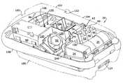
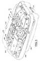
- FIGS. 2 and 3are perspective views, as viewed from the top, of a preferred embodiment of the invention with the upper and lower housing portions shown in phantom to highlight operating components of the invention;
- FIG. 4is a similar prospective view, but as viewed from the bottom of the preferred embodiment
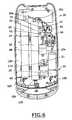
- FIGS. 5, 6 , 7 , 8 and 9are top, bottom, right side, left side and front views, respectively, of the preferred embodiment with the upper and lower housing portions removed;
- FIG. 10is a cross sectional view taken on line 10 — 10 of FIG. 5;
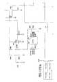
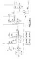
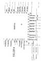
- FIGS. 11A, 11 B-a through d, 11 C-a through d, 11 D-a through d, 11 E-a through d, and 11 F-a through dare diagrams of the electronic circuit used to control the components of the preferred embodiment
- FIG. 12illustrates the circuit board
- FIG. 13is a graph approximating the effect that the breathing rate of a user may have on the relative concentration of oxygen as supplied by the preferred embodiment.
- FIGS. 14 and 14Apartially illustrate an alternate embodiment in which the apparatus also includes an oxygen monitor.
- a preferred embodiment, generally indicated as 20of a combined pressure swing adsorption apparatus and oxygen conserving device, or PSA/OCD, used for fractionating at least one component, namely nitrogen, from a gaseous mixture, generally but not necessarily ambient air, by pressure swing adsorption to produce a product gas, and for delivering the product gas at specific and variable intervals upon demand by a user.
- PSA/OCDoxygen conserving device
- the general operating principles of pressure swing adsorptionare well known and are disclosed, for example, in commonly assigned U.S. Pat. Nos. 4,802,899, 5,531,807 and 5,871,564, the entire disclosures of which are incorporated by reference herein.
- ambient airis supplied to the PSA/OCD apparatus 20 through a filtered intake 21 and an intake resonator 22 to decrease the noise from the intake of the ambient air feed stream.
- the feed streamcontinues from resonator 22 and is moved from its outlet 22 a by a feed air compressor/heat exchanger assembly 24 alternatively to first and second adsorbers 30 , 32 through feed valves 40 and 42 respectively.
- Compressor/heat exchanger assembly 24 as shownincludes a compressor 24 a with an air inlet 24 c and an outlet 24 d followed by the heat exchanger 24 b.
- the respective adsorberfractionates the feed stream into the desired concentration of product gas.
- the adsorbent material used for the beds to separate nitrogen from the ambient airmay be a synthetic zeolite or other known adsorber material having equivalent properties.
- the substantial or usable portion of the oxygen enriched product gas generated by the ambient air flowing in the co-current direction sequentially in each one of the adsorbers 30 , 32is directed through the outlet 30 b, 32 b and check valve 34 , 36 of the corresponding adsorber to a product manifold 48 and then to a delivery control assembly 60 , as will be described.
- the balance of the product gas generated by each adsorberis timed to be diverted through a purge orifice 50 and a properly timed equalization valve 52 and an optional flow restrictor 53 to flow through the other adsorber 30 or 32 in the counter-current direction from the respective outlet 30 b, 32 b and to the respective inlet 30 a, 32 a of the other adsorber to purge the adsorbed, primarily nitrogen, gases.
- the counter-current product gas and purged gasesthen are discharged to the atmosphere from the adsorbers through properly timed waste valves 44 , 46 , tubing 47 and a sound absorbing muffler 48 .
- Control assembly 60to which the usable portion of the produced gas directed according to the invention, includes a mixing tank 62 which also may be filled with synthetic zeolite and serves as a reservoir to store product oxygen before delivery to the user through an apparatus outlet 68 in the pulse dose mode, a piston-type pressure control regulator 64 to regulate the product gas pressure to be delivered to the user, a bacteria filter 66 , and an oxygen delivery system 70 including a pulse dose transducer 72 including the OCD components of the electronic circuit 80 to be described, a flow control solenoid operated valve 74 , and a low pressure sensor 76 . As shown in FIGS. 2, 3 and 5 , all of the feed, waste, equalization and flow control valves are mounted on a common valve block 26 .
- delivery of the PSA generated oxygen concentrated gas from the mixing tank 62 to the useris controlled by the delivery system 70 as will now be described.
- low pressure sensor 76will detect a drop in pressure as sensed by inhalation of a user through a conventional cannula (not shown) connected to the apparatus outlet 68 by which the oxygen concentrated gas is delivered to the user.
- the transducer circuitry 72 in electronic circuit 80causes the flow control valve 74 to be opened for a predetermined time and allow a predetermined amount of the oxygen enriched gas in the mixing tank 62 to be delivered to the user through the outlet 68 .
- the amount of delivered gasis controlled by the electronic circuit 80 on circuit board 81 and using a programmable device 77 for delivery of any one of a number of effective flow rates, which in our preferred embodiment include five effective flow rates of one through five LPM at an oxygen concentration from about 80% to about 95%.
- the settingis made by the multiple position control switch 86 which, as shown in FIG. 2, is accessed by opening a hinged cover 102 on an upper housing portion 104 of the apparatus 20 .
- Cover 102preferably is held closed by a magnetic latch for both a secure closure and easy opening.
- Apparatus 20is further enclosed by a lower housing portion 106 .
- the outer housing portions 104 , 106 and the chassis 108may be of any suitable impact resistant material, but preferably is an injection molded ABS plastic. Chassis 108 as shown also includes an integrally molded carry handle 109 .
- ambient aircan enter the interior of the apparatus 20 only into the space between the access cover 102 and control panel 111 , which is accomplished by access vents 110 in a recess surrounding outlet 68 and through an elongated slot 112 formed at the hinge connection of cover 102 to the upper housing 104 . Except for the access vents 110 , the slot 112 , and at air exhaust points, the upper and lower housings 104 and 106 form an enclosed chamber with the chassis 108 .
- the ambient airis caused by a fan 92 to enter the enclosed interior enclosed chamber of apparatus 20 through an accessible inlet filter 113 on control panel 111 which may be accessed when hinged cover 102 is opened.
- Filter 113is a foam, gross-particulate filter designed to remove dust and other impurities, from the air entering the apparatus interior.
- a portion of the ambient air which enters the interior of apparatus 20 through filter 113is caused by the compressor assembly 24 to flow into the intake 21 of the resonator 22 through a second filter 114 made of felt material to further filter the air to be fractionated.
- the balance of the ambient air flowing into the interior of the apparatus 20is, according to the invention, caused to flow in a controlled path throughout the enclosed interior of the apparatus to cool the operating elements of the PSA assembly.
- fan 92which is positioned in an angled opening 93 in chassis 108 as shown in FIG. 10, also functions to move the balance of the ambient air in a controlled path through the enclosed spaces in the apparatus 20 between the chassis 108 and the cover portions 104 , 106 .
- the operating elements mounted on the top side of the central chassis 108are the intake 21 , control switch 86 , accessible through control panel 111 , to activate the apparatus and set the flow rate, a removable battery pack 90 , the valve block 26 , the compressor assembly 24 , the circuit board 81 , the fan 92 , and the cannula fitting 68 .
- Mounted on the bottom side of the central chassisare the resonator 22 , the adsorber beds 30 , 32 , the muffler 46 , the mixing tank 62 , and the pressure control regulator 64 .
- the portion of the ambient air entering at filtered inlet 113 and not directed through filter 114is directed through the apparatus by a series of horizontal and vertical baffles 120 formed with chassis 108 and which direct the ambient cooling air entering the access space through filtered inlet 113 , by the draw from fan 92 , sequentially over the circuit board 81 , the valve block 26 and compressor assembly 24 .
- the ambient cooling airis then drawn by fan 92 to the underside of the chassis 108 through opening 93 , first through a plenum or duct (not shown) formed on the bottom side of chassis 108 , to direct all of the cooling air toward the front of the space formed between chassis 108 and lower housing 106 .
- the cooling airis then redirected to flow toward the back of apparatus 20 over the resonator 22 , adsorber beds 30 , 32 , mixing tank 62 , muffler 46 and pressure regulator 64 before being expelled through grillwork 124 at the rear end of the lower housing portion 106 .
- all of the heat generating components mounted on circuit board 81which is mounted on the top of chassis 108 , are positioned on the rear side of the circuit board in the direct flow of the cooling air as it enters the interior of apparatus 20 .
- a combined PSA/OCD based on the preferred embodimentis easily able to deliver an oxygen concentration, at standard atmosphere of about 90% ⁇ 3% in pulse doses at every inhalation cycle of about 8.75 mL for the setting of 1 LPM, about 17.5 mL for the setting of 2 LPM, about 26.25 mL for the setting of 3 LPM, about 35.0 mL for the setting of 4 LPM, and about 43.75 mL for the setting of 5 LPM.
- this performancecan be achieved in an apparatus with a weight of less than about 10 lb., measuring less overall than 17′′ in length, 8′′ in width and 6′′ in height, and emitting less than about 55 decibels noise level.
- each of the adsorber beds 30 , 32 for a medical applicationmay be about 9.75 inches in length and about 1.25 inches in diameter, with the zeolite sieve material weighing about 81 grams for each adsorber bed.
- the beds 30 , 32are spring biased in order not to “fluidize” the sieve material in their depressurization or pressure equalization stages.
- the feed stream of airis provided at a nominal rate of about 7 liters per minute, to produce a product gas within an approximate operating pressure range from about 19 psia to about 23 psia, or about 21 psia when powered at about 13 volts, with the setting at 3 LPM and a user breathing rate of about fifteen breaths per minute.
- circuit components on the printed circuit board 81control the PSA cycle and the pulse dosing of oxygen from the apparatus. Those components are illustrated in FIGS. 11 a-f and 12 and function as described in the attached detailed description of circuit 80 .
- the concentration of the oxygen supplied by the apparatus for each flow control switch settingis dependent on system pressure, operating voltage (battery or external supply), and patient breathing rate within allowable ranges of these parameters.
- the microprocessorcalculates, from continuous or sampled readings of the selector position, the operating voltage, and the frequency of actuation of the OCD, the predictable oxygen concentration being delivered to the user. If any of these approach the upper or lower thresholds, for example as low as 85% oxygen concentration, an intermittent alarm may be provided to warn the user that he or she can continue to use the apparatus but should take action to prevent the performance from falling outside of specifications. If any of the parameters regularly exceeds the predetermined thresholds, for example at a calculated oxygen concentration of 80% or less, the alarm may be programmed to sound continuously to notify the user that the performance of apparatus 20 is outside of specifications and its use discontinued.
- the graph of FIG. 13illustrates the effect breathing rate has on oxygen concentration for a flow control switch setting of 3 LPM and a supply voltage of 13.5 VDC.
- the embodiment shownpreferably includes an audible signal at startup of the apparatus, both audible and a red visual light alarms to signal high and low pressure, system overdraw, and an apnea event (i.e., the absence of inhalation within a preset time), audible and yellow visual light alarms to signal a low battery condition, and a pulsing green light to indicate normal apparatus operation in a pulse mode.
- an audible signal at startup of the apparatusboth audible and a red visual light alarms to signal high and low pressure, system overdraw, and an apnea event (i.e., the absence of inhalation within a preset time), audible and yellow visual light alarms to signal a low battery condition, and a pulsing green light to indicate normal apparatus operation in a pulse mode.
- the circuit 80continuously monitors the battery voltage, flow control switch setting, and the patient's breathing rate. If the breathing rate causes the apparatus to approach an overdraw condition (an oxygen concentration of about 85%) or to reach overdraw (a concentration of about 80% or less), the alarm either warns or alerts the patient to moderate his or her physical activity.
- an overdraw conditionan oxygen concentration of about 85%
- overdrawa concentration of about 80% or less
- filter 113Mounted on the circuit board and below filter 113 is a conventional liquid crystal display hour meter 122 to record the cumulative time of use of the apparatus, so that the recommended service scheduling can be met.
- hour meter 122can be easily seen by the user.
- a test button 87 accessible from the control panelmay be actuated to cause the apparatus 20 to cycle through its various operating modes to ensure that operating components of the apparatus function as designed.
- An accessible reset button 130enables a service technician to reset the counter on the hour meter after servicing.
- a temperature switch 124is provided to shut off power to the compressor assembly 24 in the event of overheating as a result of, e.g., cooling fan failure or air inlet/outlet blockage.
- the main circuit board 81is based on the PIC 16F74-1/L microcontroller 77 , having an external crystal oscillator 82 with a clock rate of 1 Mhz.
- the microcontroller 77receives input data from: 1.) the analog pressure conditioning circuit (for the oxygen conserving device, hereinafter OCD), 2.) the battery management system with a nominal 1.5 amp constant current generator, 3.) the valve control 72 (for the pressure swing adsorption, hereinafter PSA), 4.) a rotary switch 86 , 5.) the purity test button 87 , and 6.) the pressure sensor 76 to indicate sensor pressure.
- the microcontroller 77communicates with the operator via three LEDs 125 , 126 and 127 , and an audible alarm 128 . Additionally, an hour meter 122 will indicate compressor on time.
- the battery reset circuitdisables the 5V regulator 97 when the battery voltage drops below a reference voltage, effectively shutting down the majority of the circuit board and minimizing the current drawn from the battery.
- the second circuitcontrols the switching response time of the on-board circuit relay K1 100 , providing uninterrupted service if the AC adapter is removed.
- the relay 100is energized when the external power supply is plugged into the unit, so that the unit is energized from the external supply only. When the external supply is unplugged the relay 100 will de-energize, and the unit will operate on battery power.
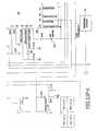
- FIG. 11Bis a schematic diagram of the pressure signal conditioning circuit or OCD.
- a quadruple operational amplifier, OPA4336EA250is used in the analog section of the circuitry.
- Two of the four amplifiers, U8-A 83 and U8-B 84have inputs connected directly to the differential output of the pressure transducer U9 78 .
- An optimum offset voltage on Pin 7 of U8-B 84was determined to be 3.475 ⁇ 0.025 volts. This voltage is set by adjusting trimmer R11 79 .
- the gain of this stageis over 400; as a result, the pressure signal on Pin 7 of U8-B 84 is in the right range for the following stage to make decisions regarding patient breathing.
- Amplifier U8-C 88is configured as a comparator.
- Pin 12 of 88represents the average pressure in the patient cannula during the last four-to-five breaths, while Pin 11 of 88 instantaneously follows the breathing pressure.
- a vacuum generated during the initial part of each inhalationchanges the output of U8-C 88 from low to high, signaling a new inhalation to the microcontroller 77 .
- One of the advantages of using this circuitis its relative immunity to small or slow offset drifts caused by temperature changes or component aging.
- the “floating” average pressure signalautomatically follows changes in the breathing pattern.
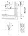
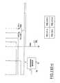
- the battery management systemconsists of a benchmark BQ2002TSN (U1) battery management chip 91 , a Burr-Brown operational amplifier, UPA2334UA (U13) 146 , an Astec DC—DC 5 volt converter (DC- 1 ) 89 , an MJE3055T power transistor (Q6) 131 , and two supporting MOSFET transistors, IRF9Z34 (Q4) 132 and BS170 (Q5) 133 .
- the operation of this circuitfollows:
- the microcontroller 77controls the supply voltage (VDD) to the battery-management chip 91 .
- the battery-management chip 91reads battery voltage via resistors R1 134 and R2 135 .
- the microcontroller Pin 36supplies five volts to Pin 6 of the battery-management chip 91 , turning it on.
- the microcontroller Pin 36When power is first applied to the battery-management chip, it goes to a fast-charge charging cycle. The cycle causes Pin 8 of the battery-management chip 91 to output five volts and turn on Q5 133 which turns on Q4 132 , allowing a nominal 1.5 amps of current to flow into the battery.
- the nominal 1.5 amps of currentis derived from the constant-current generator that consists of U13 99 , a DC—DC 5 volt converter (DC- 1 ) 89 , power transistor (Q6) 131 ; and two supporting MOSFET transistors (Q4) 132 and (Q5) 133 .
- the operation of this circuitfollows:
- the DC—DC converter 89raises the external 13.5 volt power-supply voltage to 18.5 volts.
- Q5 133turns on and then turns on Q4 132 .
- the Burr Brown op-amp U13 99measures the differential voltage across R65 136 .
- the Burr-Brown op-ampmaintains Q6 131 so that 1.5 amps of current flows through it as long as Pin 8 of the battery-management chip 91 is at logic high (five volts).
- the battery-management chip 91monitors the charging cycle through Pin # 5 , the TS pin.
- This pinin conjunction with a 10 k thermistor 137 in the battery pack, provides temperature feedback from the battery pack in the form of voltage.
- the TS pinsamples the voltage from the battery every 19 seconds and compares it to the three samples measured earlier. If the voltage has fallen 25 mV or more, fast charge is terminated.
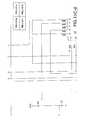
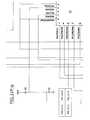
- the valve controlis illustrated in FIG. 11 D.
- the microcontrollercontrols valve drivers U5 138 , U6 139 and U7 140 . These consist of the PSA valves 40 , 42 , 44 , 46 , 52 and the OCD valve 74 .
- Each PSA valveis turned on via the drivers according to the following timing sequence:
- the OCD valve 74is turned on every time the pressure-signaling conditioning circuit detects a breath from the user. The time that the OCD valve 74 is on depends upon the setting of the flow-selector switch 86 .
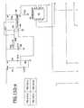
- the rotary switch 86is illustrated in FIG. 11 E.
- the microcontroller 77reads the condition of the rotary switch 86 to determine whether the unit is on or off and what flow selection the user has chosen.
- the unitis in the OFF position when the microcontroller 77 reads the logic low on Pin 28 of the microcontroller 77 .
- a logic high on Pin 28 of the microcontroller 77indicates that the unit has been turned ON.
- the microcontroller 77reads the flow selection of the rotary switch 86 via Pins 29 through 33 of microcontroller 77 .
- the flow selectionis read for Position 1 when a logic low is read on Pin 29 of the microcontroller 77 .
- Flow selection 2is read when a logic low is read on Pin 30 of the microcontroller 77 .
- the purity test button SW3 87is a normally-open switch and is used to put the microcontroller 77 in one of two test modes.
- a logic highis applied to Pin 18 of the microcontroller 77 , indicating normal operation.
- the microcontroller 77reads a logic low on Pin 18 and reads the condition of the rotary switch SW2 86 to determine which of the two test modes it must run. If the rotary switch 86 is set to any flow selection between 1 and 4, the unit breathes 15 breaths per minute defaulting to flow selection 3. This is the first-test condition.
- the second testis initiated if the flow-selector switch is set to Position 5 and the purity test switch SW3 87 is pressed. In this test mode, the unit breaths the following breaths per minute for three-minute intervals: 15, 17.5, 20, 22.5, 25, 27.5, 30. Both test modes continue until the unit is switched off. When the unit is turned back on again, it resumes normal operation.
- the rotary switch 86is illustrated in FIG. F.
- the microcontroller 77reads the condition of the rotary switch 86 to determine whether the unit is on or off and what flow selection the user has chosen.
- the unitis in the OFF position when the microcontroller 77 reads the logic low on Pin 28 of the microcontroller 77 .
- a logic high on Pin 28 of the microcontroller 77indicates that the unit has been turned ON.
- the microcontroller 77reads the flow selection of the rotary switch via Pins 29 through 33 of microcontroller 77 .
- the flow selectionis read for Position 1 when a logic low is read on Pin 29 of the microcontroller 77 .
- Flow selection 2is read when a logic low is read on Pin 30 of the microcontroller 77 .
- the purity test button SW3 87is a normally-open switch and is used to put the microcontroller 77 in one of two test modes.
- a logic highis applied to Pin 18 of the microcontroller (U2) 77 , indicating normal operation.
- the microcontroller 77reads a logic low on Pin 18 and reads the condition of the rotary switch SW2 86 to determine which of the two test modes it must run. If the rotary switch SW1 is set to any flow selection between 1 and 4, the unit breathes 15 breaths per minute defaulting to flow selection 3. This is the first-test condition.
- the second testis initiated if the flow-selector switch is set to Position 5 and the purity test switch SW3 87 is pressed. In this test mode, the unit breaths the following breaths per minute for three-minute intervals: 15, 17.5, 20, 22.5, 25, 27.5, 30. Both test modes continue until the unit is switched off. When the unit is turned back on again, it resumes normal operation.
- the pressure sensor 76is illustrated in FIG. 11 A.
- the high-pressure circuitryis based on Motorola pressure sensor MPX5500DP (U10) 76 .
- the microcontroller 77 Pin 5reads the analog output from the pressure sensor 76 .
- the microcontroller 77signals a system failure. This condition repeats itself if the system pressure is 36 psi or higher.
- the Three LED's (one red, one green, one yellow) and a buzzer 128are also illustrated in FIG. 11 F and FIG. 11 D.
- the green LED, D9 125is used during a 1.2 second start-up sequence to tell the user that he or she is turning on the unit. Green LED 130 also will flash each time a breath is detected and a pulse dose is delivered to the user.
- the yellow LED, D10 126is used for battery charging when the unit is in the OFF condition. When the yellow LED is flashing, the unit is charging the battery. When the yellow LED 126 comes to a constant, non-flashing state, the battery is fully charged. This process takes approximately two hours and is visible only when the unit is in the OFF position.
- the microcontroller 77When the unit is turned ON and running off the external battery (no external power supply), the microcontroller 77 reads the battery voltage via resistor divider network R67, R68, and Pin 11 of microcontroller 77 . When the battery voltage decays to 10.9 volts, the yellow LED 126 and the buzzer 128 come on for one second for every five seconds they are off. This indicates to the user that the battery is in a low condition and should be charged or replaced to continue operation. When the battery decays to 10.5 volts, the unit automatically shuts down and flashes the yellow LED 126 and buzzer 128 on and off at a frequency of 500-milliseconds. The red LED 127 is used as a pre-condition alarm, a system failure alarm, or an apnea alarm. The table below lists the alarms and alarm functions.
- 1-second beep Battery-YELLOW Batteryrequires Replace the battery, or plug every 5 seconds Flashing charging the apparatus into an automobile cigarette lighter or a 120 volt outlet within 5 minutes.
- 1 ⁇ 2-second beep Battery-YELLOW Battery voltageis too Replace the battery, or plug every 1 ⁇ 2 second. Flashing low to operate the apparatus into an apparatus. automobile cigarette lighter or a 120 volt outlet immediately.
- Three 1 ⁇ 2-second Alarm-RED Breathing rateis Reduce activity, and/or beeps followed Flashing approaching the locate another source of by a 5 second threshold of the oxygen.
- the apparatuscan pause apparatus capacity; or be operated in this the apparatus is condition. approaching general malfunction.
- 1 ⁇ 2-second beep Alarm-RED Breathing rateis Reduce activity, and/or every 1 ⁇ 2 second Flashing exceeding the capacity locate and use another of the apparatus. source of oxygen. Contact your Equipment Provider. 1 ⁇ 2-second beep Alarm-RED General malfunction Change to another source of every 1 ⁇ 2 second Non-flashing of the apparatus has oxgen, and contact occurred. equipment provider. Turn off the apparatus.
- the HR1 hour meter 122 as illustrated in FIG. 11Dcollects time when the compressor is running, up to 99,999 hours for 11 years.
- There is a reset button, SW1 130that when pressed by a service technician, resets the hours to 0.
- the meterneeds no external power source to maintain memory content.
- the battery-reset circuit as shown by FIG. 11Dconsists of a micropower comparator, TLV3401IDR (U3) 94 , a 1.2 volt reference, D13 95 , two resistor divider networks R4, R6 and R5, R6, a P-Channel MOSFET transistor ZXM61P03CT (Q7) 96 , and a five-volt regulator, LM78L05ACM (U4) 97 .
- the voltage divider network R5 and R6is higher than the 1.2 volt reference, which keeps the output Pin 6 of the micropower comparator U3 94 l low.
- the on-board relay circuit as shown in FIG. 11Bconsists of comparator U11 (LM311) 98 and voltage reference U12 (LM431) 99 .
- This circuitspeeds up the switching time of the relay when the external power supply is unplugged from the unit and the battery must take over.
- LM311)comparator
- U12voltage reference U12
- the circuitfunctions as follows: when the external power supply is first plugged into the unit, the voltage at resistor divider network R58 and R59 is above the three-volt reference set by U12 (LM431) 99 . This condition forces the output of U11 (LM311) 98 to be high, thereby turning on the relay K1 100 as shown in FIG. 11 C.
- the voltage across the relay coilbegins to decay.
- resistor dividers R58 and R59divide this voltage so that it is below the three-volt reference set by U12 (LM431) 99 . This forces the output of U11 (LM311) 98 low, closing the relay (K1) 100 regardless of what is happening with the compressor. This prevents microcontroller resets during external and battery power-supply exchanges.
- the microprocessormonitors battery voltage, system pressure and flow rate. Additional embodiments are planned to include an Oxygen monitoring system.
- One possible position for the oxygen monitoring system 147is illustrated in FIG. 14 .
- This particular embodimentdepicts the oxygen monitoring system 147 in-line before the oxygen delivery system.
- the oxygen monitoring system 147is positioned between the pressure control regulator 64 and the flow control valve, however other possible positions are possible.
- the output of the oxygen sensor 147will be monitored by the microprocessor 77 , as shown in FIG. 14 a.
- the oxygen monitoring system 147will share microprocessor 77 pin 11 with the battery monitoring system 149 .
- a switching circuit 148 for switching between the oxygen monitoring system 147 and the battery monitoring system 149is shown in FIG. 14 a
- valve block 26are open to eliminate any back pressure and then either left open or closed in sequence through a timing mechanism of conventional switches and relay switches in programmable circuit 80 .
- each of the feed, waste, and equalization valvesis preferably a solenoid-type valve responsive to a turning on or shutting off of power to the valve, product-producing and regeneration operations are automatically controlled in apparatus 20 by automatically controlling the amount of time that each of the feed, waste, and equalization valves are opened and closed.
- the apparatuscan be powered any one of three sources, including a removable, nickel metal hydride battery pack which when fully charged can supply power to the apparatus for approximately 50 minutes without external power; an AC adapter to connect the apparatus at connector 126 to a nominal 120 volt AC outlet to convert the 120 volt AC to 13.5 volt DC; and a “cigarette lighter” adapter for a similar connection to a nominal 13.5 volt DC automobile battery.
- both the AC adapter and the automobile batterycan power the apparatus and recharge the battery pack simultaneously, taking approximately two hours to charge the battery pack.
- the battery packmay be detached from the apparatus by conventional plug means to facilitate the use of fully-charged spare battery packs.
Landscapes
- Health & Medical Sciences (AREA)
- Chemical & Material Sciences (AREA)
- Engineering & Computer Science (AREA)
- Chemical Kinetics & Catalysis (AREA)
- General Chemical & Material Sciences (AREA)
- Emergency Medicine (AREA)
- Analytical Chemistry (AREA)
- Oil, Petroleum & Natural Gas (AREA)
- Life Sciences & Earth Sciences (AREA)
- Public Health (AREA)
- Veterinary Medicine (AREA)
- Pulmonology (AREA)
- Animal Behavior & Ethology (AREA)
- General Health & Medical Sciences (AREA)
- Heart & Thoracic Surgery (AREA)
- Anesthesiology (AREA)
- Biomedical Technology (AREA)
- Hematology (AREA)
- Pharmacology & Pharmacy (AREA)
- Nuclear Medicine, Radiotherapy & Molecular Imaging (AREA)
- Medicinal Chemistry (AREA)
- Bioinformatics & Cheminformatics (AREA)
- Organic Chemistry (AREA)
- Separation Of Gases By Adsorption (AREA)
- Oxygen, Ozone, And Oxides In General (AREA)
- Pharmaceuticals Containing Other Organic And Inorganic Compounds (AREA)
Abstract
Description
| Open Valve | Open Time | ||
| FB, | 6 sec | ||
| FA, | 1 sec | ||
| FA, | 6 sec | ||
| FB, | 1 sec | ||
| FA = Feed valve A (40) | |||
| FB = Feed valve B (42) | |||
| WA = Waste valve A (44) | |||
| WB = Waste valve B (46) | |||
| EQ = Equalizing valve (52) | |||
| Flow Selector | |||
| Setting | On | ||
| 1 | 82 | ||
| 2 | 120 | ||
| 3 | 172 | ||
| 4 | 250 | ||
| 5 | 310 ms | ||
| TABLE of Alarms |
| Audible Alarm | Visual Alarm | Indication | What to do |
| 5-second | None | unit has been turned on. | You may begin to operate the |
| continuous | |||
| audible alarm at | |||
| startup | |||
| None | Battery-Yellow | Battery is charging. | If the unit is unplugged |
| Flashing when unit | from the power source and | ||
| is OFF and plugged | used, the battery does not | ||
| into power source | supply power for the full 50 | ||
| minutes. | |||
| None | Battery-Yellow | Battery is fully | If the unit is unplugged |
| Non-Flashing when | charged. | from the power source and | |
| unit is OFF and | used, the battery supplies | ||
| plugged into power | power for the full 50 | ||
| source | minutes. | ||
| Continuous | Alarm-RED | No breath has been | Check the cannula |
| audible alarm | Non-flashing | sensed for 30 seconds. | connection. Ensure that |
| you are breathing through | |||
| your nose. If the alarm | |||
| persists, contact your | |||
| Equipment Provider. | |||
| 1-second beep | Battery-YELLOW | Battery requires | Replace the battery, or plug |
| every 5 seconds | Flashing | charging | the apparatus into an |
| automobile cigarette lighter | |||
| or a 120 volt outlet within 5 | |||
| minutes. | |||
| ½-second beep | Battery-YELLOW | Battery voltage is too | Replace the battery, or plug |
| every ½ second. | Flashing | low to operate | the apparatus into an |
| apparatus. | automobile cigarette lighter | ||
| or a 120 volt outlet | |||
| immediately. | |||
| Three ½-second | Alarm-RED | Breathing rate is | Reduce activity, and/or |
| beeps followed | Flashing | approaching the | locate another source of |
| by a 5 second | threshold of the | oxygen. The apparatus can | |
| pause | apparatus capacity; or | be operated in this | |
| the apparatus is | condition. | ||
| approaching general | |||
| malfunction. | |||
| ½-second beep | Alarm-RED | Breathing rate is | Reduce activity, and/or |
| every ½ second | Flashing | exceeding the capacity | locate and use another |
| of the apparatus. | source of oxygen. Contact | ||
| your Equipment Provider. | |||
| ½-second beep | Alarm-RED | General malfunction | Change to another source of |
| every ½ second | Non-flashing | of the apparatus has | oxgen, and contact |
| occurred. | equipment provider. Turn | ||
| off the apparatus. | |||
Claims (16)
Priority Applications (2)
| Application Number | Priority Date | Filing Date | Title |
|---|---|---|---|
| US10/354,275US6764534B2 (en) | 2002-01-31 | 2003-01-30 | Portable oxygen concentrator |
| US10/762,671US6949133B2 (en) | 2002-01-31 | 2004-01-22 | Portable oxygen concentrator |
Applications Claiming Priority (2)
| Application Number | Priority Date | Filing Date | Title |
|---|---|---|---|
| US35356302P | 2002-01-31 | 2002-01-31 | |
| US10/354,275US6764534B2 (en) | 2002-01-31 | 2003-01-30 | Portable oxygen concentrator |
Related Child Applications (1)
| Application Number | Title | Priority Date | Filing Date |
|---|---|---|---|
| US10/762,671ContinuationUS6949133B2 (en) | 2002-01-31 | 2004-01-22 | Portable oxygen concentrator |
Publications (2)
| Publication Number | Publication Date |
|---|---|
| US20030167924A1 US20030167924A1 (en) | 2003-09-11 |
| US6764534B2true US6764534B2 (en) | 2004-07-20 |
Family
ID=27663222
Family Applications (2)
| Application Number | Title | Priority Date | Filing Date |
|---|---|---|---|
| US10/354,275Expired - LifetimeUS6764534B2 (en) | 2002-01-31 | 2003-01-30 | Portable oxygen concentrator |
| US10/762,671Expired - LifetimeUS6949133B2 (en) | 2002-01-31 | 2004-01-22 | Portable oxygen concentrator |
Family Applications After (1)
| Application Number | Title | Priority Date | Filing Date |
|---|---|---|---|
| US10/762,671Expired - LifetimeUS6949133B2 (en) | 2002-01-31 | 2004-01-22 | Portable oxygen concentrator |
Country Status (4)
| Country | Link |
|---|---|
| US (2) | US6764534B2 (en) |
| EP (1) | EP1485188A4 (en) |
| JP (2) | JP4473580B2 (en) |
| WO (1) | WO2003064009A1 (en) |
Cited By (88)
| Publication number | Priority date | Publication date | Assignee | Title |
|---|---|---|---|---|
| US20040149133A1 (en)* | 2002-01-31 | 2004-08-05 | Mccombs Norman R. | Portable oxygen concentrator |
| US20050045040A1 (en)* | 2003-09-02 | 2005-03-03 | Airsep Corporation | Sound enclosure for portable oxygen concentrators |
| US20050072298A1 (en)* | 2003-10-07 | 2005-04-07 | Deane Geoffrey Frank | Portable gas fractionalization system |
| US20050072306A1 (en)* | 2003-10-07 | 2005-04-07 | Deane Geoffrey Frank | Portable gas fractionalization system |
| US20050072423A1 (en)* | 2003-10-07 | 2005-04-07 | Deane Geoffrey Frank | Portable gas fractionalization system |
| US20050257686A1 (en)* | 2004-05-21 | 2005-11-24 | Occhialini James M | Weight-optimized portable oxygen concentrator |
| US20060086070A1 (en)* | 2004-10-26 | 2006-04-27 | Althouse Michael D | Trigger mechanism for dust filter pulse cleaning system |
| US20060099096A1 (en)* | 2004-11-08 | 2006-05-11 | Shaffer Robert W | Scroll pump system |
| US20060102181A1 (en)* | 2004-10-12 | 2006-05-18 | Airsep Corporation | Oxygen concentrator with variable temperature and pressure sensing control means |
| US20060117957A1 (en)* | 2004-10-12 | 2006-06-08 | Airsep Corporation | Mini-portable oxygen concentrator |
| US20060174873A1 (en)* | 2005-02-09 | 2006-08-10 | Vbox, Incorporated | Product pump for an oxygen concentrator |
| US20060174877A1 (en)* | 2005-02-09 | 2006-08-10 | Vbox, Incorporated | Portable oxygen concentrator with a docking station |
| US20060174880A1 (en)* | 2005-02-09 | 2006-08-10 | Vbox, Incorporated | Ambulatory oxygen concentrator containing a three phase vacuum separation system |
| US20060174882A1 (en)* | 2005-02-09 | 2006-08-10 | Vbox, Incorporated | Method of controlling the rate of oxygen produced by an oxygen concentrator |
| US20060174878A1 (en)* | 2005-02-09 | 2006-08-10 | Vbox, Incorporated | Low power ambulatory oxygen concentrator |
| US20060174874A1 (en)* | 2005-02-09 | 2006-08-10 | Vbox, Incorporated | Adsorbent cartridge for oxygen concentrator |
| US20060174871A1 (en)* | 2005-02-09 | 2006-08-10 | Vbox, Incorporated | Ambulatory oxygen concentrator with high efficiency adsorbent |
| US20060174872A1 (en)* | 2005-02-09 | 2006-08-10 | Vbox, Incorporated | Method and apparatus for controlling the purity of oxygen produced by an oxygen concentrator |
| US20060174876A1 (en)* | 2005-02-09 | 2006-08-10 | Vbox, Incorporated | Personal oxygen concentrator |
| US20060174875A1 (en)* | 2005-02-09 | 2006-08-10 | Vbox, Incorporated | Ambulatory oxygen concentrator containing a power pack |
| US20060174881A1 (en)* | 2005-02-09 | 2006-08-10 | Vbox, Incorporated | Method of providing ambulatory oxygen |
| WO2006108092A1 (en) | 2005-04-05 | 2006-10-12 | Oxytec Medical Corporation | Portable oxygen concentrator |
| US20060230929A1 (en)* | 2005-04-05 | 2006-10-19 | Bliss Peter L | Portable oxygen concentrator |
| US20070006880A1 (en)* | 2003-05-16 | 2007-01-11 | Lee Smith | Apparatus for delivering pressurized fluid |
| US20070137487A1 (en)* | 2005-12-20 | 2007-06-21 | Whitley Roger D | Portable medical oxygen concentrator |
| US20070227360A1 (en)* | 2006-04-03 | 2007-10-04 | Atlas Charles R | Portable oxygen concentrator |
| WO2006017398A3 (en)* | 2004-08-04 | 2007-11-01 | Pulmonetic Systems Inc | Method and apparatus for attenuating compressor noise |
| US20080053310A1 (en)* | 2006-04-03 | 2008-03-06 | Bliss Peter L | Compressors and methods for use |
| US7368005B2 (en) | 2005-04-05 | 2008-05-06 | Respironics Oxytec, Inc. | Portable oxygen concentrator |
| US7438745B2 (en) | 2003-10-07 | 2008-10-21 | Inogen, Inc. | Portable gas fractionalization system |
| US20080257145A1 (en)* | 2007-04-20 | 2008-10-23 | Invacare Corporation | Product gas concentrator and method associated therewith |
| US7455717B2 (en) | 2004-10-25 | 2008-11-25 | Invacare Corporation | Apparatus and method of providing concentrated product gas |
| US20090142213A1 (en)* | 2007-12-03 | 2009-06-04 | Pulmonetic Systems, Inc. | Roots-type blower reduced acoustic signature method and apparatus |
| US20090167698A1 (en)* | 2006-04-03 | 2009-07-02 | Altas Charles R | User interface for a portable oxygen concentrator |
| US20090205494A1 (en)* | 2008-02-20 | 2009-08-20 | Mcclain Michael S | Single manifold assembly for oxygen-generating systems |
| US20090205493A1 (en)* | 2008-02-20 | 2009-08-20 | Thompson Loren M | Method of removing water from an inlet region of an oxygen generating system |
| US20090214393A1 (en)* | 2008-02-22 | 2009-08-27 | Chekal Michael P | Method of generating an oxygen-enriched gas for a user |
| US20090211443A1 (en)* | 2008-02-21 | 2009-08-27 | Youngblood James H | Self-serviceable filter for an oxygen generating device |
| US20090211438A1 (en)* | 2008-02-21 | 2009-08-27 | Thompson Loren M | Method of determining the purity of oxygen present in an oxygen-enriched gas produced from an oxygen delivery system |
| US20090229460A1 (en)* | 2008-03-13 | 2009-09-17 | Mcclain Michael S | System for generating an oxygen-enriched gas |
| US7607437B2 (en) | 2003-08-04 | 2009-10-27 | Cardinal Health 203, Inc. | Compressor control system and method for a portable ventilator |
| US20090277333A1 (en)* | 2006-07-03 | 2009-11-12 | Hideyuki Sakurai | Oxygen concentrating device |
| US7617826B1 (en) | 2004-02-26 | 2009-11-17 | Ameriflo, Inc. | Conserver |
| USD606655S1 (en) | 2008-06-27 | 2009-12-22 | Inova Labs, Llc | Portable oxygen concentrator |
| US7686870B1 (en) | 2005-12-29 | 2010-03-30 | Inogen, Inc. | Expandable product rate portable gas fractionalization system |
| US7722700B2 (en) | 2006-09-18 | 2010-05-25 | Invacare Corporation | Apparatus and method of providing concentrated product gas |
| US20110017063A1 (en)* | 2009-07-22 | 2011-01-27 | Van Brunt Nicholas P | Apparatus for separating oxygen from ambient air |
| US8075676B2 (en) | 2008-02-22 | 2011-12-13 | Oxus America, Inc. | Damping apparatus for scroll compressors for oxygen-generating systems |
| US8118024B2 (en) | 2003-08-04 | 2012-02-21 | Carefusion 203, Inc. | Mechanical ventilation system utilizing bias valve |
| US20120055474A1 (en)* | 2010-09-07 | 2012-03-08 | Wilkinson William R | Methods and systems for providing oxygen enriched gas |
| US8146592B2 (en) | 2004-02-26 | 2012-04-03 | Ameriflo, Inc. | Method and apparatus for regulating fluid flow or conserving fluid flow |
| US8156937B2 (en) | 2003-08-04 | 2012-04-17 | Carefusion 203, Inc. | Portable ventilator system |
| US20120167883A1 (en)* | 2010-12-30 | 2012-07-05 | Brenton Taylor | Advanced portable oxygen concentrator |
| US8267081B2 (en) | 2009-02-20 | 2012-09-18 | Baxter International Inc. | Inhaled anesthetic agent therapy and delivery system |
| US20120255446A1 (en)* | 2011-04-05 | 2012-10-11 | Duerr Technik Gmbh & Co. Kg | Oxygen generator |
| US8297279B2 (en) | 2003-08-04 | 2012-10-30 | Carefusion 203, Inc. | Portable ventilator system |
| US20130061747A1 (en)* | 2011-09-09 | 2013-03-14 | Torosoleil, Llc | Dynamic and continuous control for pressure swing adsorption |
| WO2013038315A1 (en) | 2011-09-13 | 2013-03-21 | Koninklijke Philips Electronics N.V. | Portable oxygen concentrator with integrated manifold |
| WO2013038319A1 (en) | 2011-09-13 | 2013-03-21 | Koninklijke Philips Electronics N.V. | Proportional oxygen conserving device with flow sensing cross-reference to related applications |
| WO2013038342A1 (en) | 2011-09-13 | 2013-03-21 | Koninklijke Philips Electronics N.V. | Portable oxygen concentrator |
| US8616207B2 (en) | 2010-09-07 | 2013-12-31 | Inova Labs, Inc. | Oxygen concentrator heat management system and method |
| US8794237B2 (en) | 2007-09-06 | 2014-08-05 | Inova Labs, Inc. | Oxygen concentrator apparatus and method having flow restricted coupling of the canisters |
| US8888711B2 (en) | 2008-04-08 | 2014-11-18 | Carefusion 203, Inc. | Flow sensor |
| US9067174B2 (en) | 2012-03-09 | 2015-06-30 | Invacare Corporation | System and method for concentrating gas |
| US9120050B2 (en) | 2008-04-21 | 2015-09-01 | Invacare Corporation | Product gas concentrator utilizing vacuum swing adsorption and method associated therewith |
| US9132377B2 (en) | 2012-03-09 | 2015-09-15 | Invacare Corporation | System and method for concentrating gas |
| US20150273174A1 (en)* | 2014-03-28 | 2015-10-01 | Caire Inc. | Controlling Oxygen Concentrator Timing Cycle Based on Flow Rate of Oxygen Output |
| US9266053B2 (en) | 2012-06-18 | 2016-02-23 | Invacare Corporation | System and method for concentrating gas |
| US9440179B2 (en) | 2014-02-14 | 2016-09-13 | InovaLabs, LLC | Oxygen concentrator pump systems and methods |
| US9440180B2 (en) | 2012-10-12 | 2016-09-13 | Inova Labs, Llc | Oxygen concentrator systems and methods |
| US9440036B2 (en) | 2012-10-12 | 2016-09-13 | InovaLabs, LLC | Method and systems for the delivery of oxygen enriched gas |
| US9717876B2 (en) | 2012-10-12 | 2017-08-01 | Inova Labs, Inc. | Dual oxygen concentrator systems and methods |
| US9956371B2 (en) | 2015-03-24 | 2018-05-01 | Ventec Life Systems, Inc. | Ventilator with integrated cough-assist |
| US10576235B2 (en) | 2017-05-18 | 2020-03-03 | Tokitae Llc | Management of a therapeutic oxygen delivery system |
| US10773049B2 (en) | 2016-06-21 | 2020-09-15 | Ventec Life Systems, Inc. | Cough-assist systems with humidifier bypass |
| US11077924B1 (en)* | 2018-03-21 | 2021-08-03 | Brownie's Marine Group, Inc. | System for adjusting pressure limits based on depth of the diver(s) |
| US11191915B2 (en) | 2018-05-13 | 2021-12-07 | Ventec Life Systems, Inc. | Portable medical ventilator system using portable oxygen concentrators |
| US11247015B2 (en) | 2015-03-24 | 2022-02-15 | Ventec Life Systems, Inc. | Ventilator with integrated oxygen production |
| US11260338B2 (en) | 2018-08-09 | 2022-03-01 | O2 Air-Sea, Llc | Oxygen generation device |
| US11278697B2 (en) | 2009-10-05 | 2022-03-22 | Separation Design Group Ip Holdings, Llc | Ultra rapid cycle portable oxygen concentrator |
| US11458274B2 (en) | 2016-05-03 | 2022-10-04 | Inova Labs, Inc. | Method and systems for the delivery of oxygen enriched gas |
| US11565072B2 (en) | 2020-03-25 | 2023-01-31 | Jeffrey L. James | Assisted walking device and method of use |
| US11915570B2 (en) | 2020-07-16 | 2024-02-27 | Ventec Life Systems, Inc. | System and method for concentrating gas |
| US11931689B2 (en) | 2020-07-16 | 2024-03-19 | Ventec Life Systems, Inc. | System and method for concentrating gas |
| US12172121B2 (en) | 2020-07-16 | 2024-12-24 | Ventec Life Systems, Inc. | System and method for concentrating gas |
| US12226733B2 (en) | 2020-07-16 | 2025-02-18 | Ventec Life Systems Inc. | Systems and methods for concentrating gas |
| US12347555B2 (en) | 2021-07-15 | 2025-07-01 | Ventec Life Systems, Inc. | System and method for medical device communication |
| US12440634B2 (en) | 2021-12-21 | 2025-10-14 | Ventec Life Systems, Inc. | Ventilator systems with integrated oxygen delivery, and associated devices and methods |
Families Citing this family (46)
| Publication number | Priority date | Publication date | Assignee | Title |
|---|---|---|---|---|
| FR2855433B1 (en)* | 2003-06-02 | 2007-01-12 | Air Liquide | GAS GENERATOR ASSEMBLY |
| USD510169S1 (en) | 2003-10-07 | 2005-09-27 | Inogen, Inc. | Mobility cart for transporting oxygen concentrators and related accessories |
| US20060042631A1 (en)* | 2004-08-31 | 2006-03-02 | Martin James F | Apparatus to deliver oxygen to a patient |
| CA2592445C (en)* | 2005-01-12 | 2013-12-10 | H2Gen Innovations, Inc. | Methods and apparatus for improved control of psa flow variations |
| US7288189B2 (en)* | 2005-02-11 | 2007-10-30 | Bonifer Jeffery P | Multi-faceted intake filter for an aquarium |
| US20060236719A1 (en)* | 2005-04-22 | 2006-10-26 | Lane Jonathan A | Gas stream purification method utilizing electrically driven oxygen ion transport |
| FR2906160B1 (en) | 2006-09-25 | 2009-06-05 | Air Liquide | PSA METHOD WITH COMPOSITE ADSORPTION BED FORMED OF ADSORBENT AND AGGLOMERATS OF MCP |
| US20080078392A1 (en)* | 2006-09-29 | 2008-04-03 | Pelletier Dana G | Breath detection system |
| US20080110462A1 (en)* | 2006-11-10 | 2008-05-15 | Chekal Michael P | Oxygen delivery system |
| US8187367B2 (en)* | 2006-12-31 | 2012-05-29 | Wang Dong-Lei | Portable PSA oxygen generator |
| JP3139801U (en)* | 2006-12-31 | 2008-02-28 | 冬雷 王 | Portable PSA oxygen generator |
| TW200916180A (en)* | 2007-06-08 | 2009-04-16 | Sequal Technologies Inc | Compressor cooling sytsem and method of use |
| US8302600B2 (en)* | 2008-09-30 | 2012-11-06 | Nellcor Puritan Bennett Llc | Battery management for a breathing assistance system |
| US8567396B2 (en)* | 2010-02-09 | 2013-10-29 | Invacare Corp. | Breathing gas supply system |
| DE102010011584A1 (en)* | 2010-03-16 | 2011-09-22 | Linde Ag | Generation of oxygen in hospitals |
| US20120055480A1 (en)* | 2010-09-07 | 2012-03-08 | Wilkinson William R | Ventilator systems and methods |
| US20120055477A1 (en)* | 2010-09-07 | 2012-03-08 | Wilkinson William R | Oxygen concentrator apparatus configured for high altitude use |
| US20120055478A1 (en)* | 2010-09-07 | 2012-03-08 | Wilkinson William R | Positive pressure therapy systems and methods |
| US20120055483A1 (en)* | 2010-09-07 | 2012-03-08 | Wilkinson William R | Shutdown system and method for an oxygen concentrator |
| US20120060841A1 (en)* | 2010-09-15 | 2012-03-15 | Newport Medical Instruments, Inc. | Oxygen enrichment device for ventilator |
| CA2830170C (en) | 2011-04-08 | 2019-01-15 | Vincent Gueret | Mixture of an adsorbent and a phase change material with an adapted density |
| US9649459B2 (en) | 2011-09-26 | 2017-05-16 | Resmed Paris Sas | Ventilator apparatus and method |
| US8702840B1 (en)* | 2012-01-04 | 2014-04-22 | Hvlp02, Llc | Method and apparatus for managing oxygen generating system |
| JP2013153804A (en)* | 2012-01-27 | 2013-08-15 | Fukuda Denshi Co Ltd | Oxygen concentrator |
| US9993604B2 (en) | 2012-04-27 | 2018-06-12 | Covidien Lp | Methods and systems for an optimized proportional assist ventilation |
| JP5529211B2 (en)* | 2012-06-19 | 2014-06-25 | 東京瓦斯株式会社 | Gas separator |
| US10362967B2 (en) | 2012-07-09 | 2019-07-30 | Covidien Lp | Systems and methods for missed breath detection and indication |
| US9027552B2 (en) | 2012-07-31 | 2015-05-12 | Covidien Lp | Ventilator-initiated prompt or setting regarding detection of asynchrony during ventilation |
| US9289573B2 (en) | 2012-12-28 | 2016-03-22 | Covidien Lp | Ventilator pressure oscillation filter |
| CN105407948B (en)* | 2013-01-15 | 2023-02-28 | 费雪派克医疗保健有限公司 | Gas blowing device and method and gas generating cartridge thereof |
| CN104968410B (en) | 2013-01-30 | 2019-06-04 | 皇家飞利浦有限公司 | Oxygen separation system and method of generating a stream of oxygen-enriched gas |
| US10004869B2 (en)* | 2013-12-27 | 2018-06-26 | Inogen, Inc. | Gas concentrator with removable cartridge adsorbent beds |
| USD739007S1 (en) | 2014-03-14 | 2015-09-15 | 3M Innovative Properties Company | Powered air purifying respirator unit control panel |
| US9950129B2 (en) | 2014-10-27 | 2018-04-24 | Covidien Lp | Ventilation triggering using change-point detection |
| US11400247B2 (en) | 2016-12-22 | 2022-08-02 | Fisher & Paykel Healthcare Limited | Breathing assistance apparatus |
| WO2018151958A1 (en)* | 2017-02-14 | 2018-08-23 | Caire Inc. | Extruded portable oxygen concentrator assembly |
| WO2018191385A1 (en)* | 2017-04-11 | 2018-10-18 | Carleton Life Support Systems, Inc. | System and method for monitoring psa bed health |
| WO2019182530A2 (en)* | 2017-11-08 | 2019-09-26 | Oezcan Ata | Compact portable oxygen system |
| EP3858407A4 (en)* | 2018-09-28 | 2021-11-03 | Teijin Pharma Limited | Respiration monitoring device |
| CA3119934C (en)* | 2018-11-15 | 2024-04-09 | Teijin Pharma Limited | Oxygen concentrator, control method, and control program |
| US10946161B2 (en) | 2018-12-05 | 2021-03-16 | Aires Medical LLC | Pulsed pressure swing adsorption system and method |
| US11058986B2 (en)* | 2019-01-09 | 2021-07-13 | Bining Holdings Ltd. | Medical gas production system with gas recycling |
| US11324954B2 (en) | 2019-06-28 | 2022-05-10 | Covidien Lp | Achieving smooth breathing by modified bilateral phrenic nerve pacing |
| US20230023722A1 (en)* | 2020-01-21 | 2023-01-26 | Wearair Ventures, Inc. | Efficient enriched oxygen airflow systems and methods |
| IT202000019828A1 (en)* | 2020-08-07 | 2022-02-07 | Ibd Italian Biomedical Devices S R L | LUNG VENTILATION DEVICE |
| US12415051B2 (en) | 2023-09-07 | 2025-09-16 | Roam Technologies Pty Ltd. | Oxygen concentrator |
Citations (28)
| Publication number | Priority date | Publication date | Assignee | Title |
|---|---|---|---|---|
| US3564816A (en)* | 1968-12-30 | 1971-02-23 | Union Carbide Corp | Selective adsorption process |
| US3636679A (en)* | 1971-01-04 | 1972-01-25 | Union Carbide Corp | Selective adsorption gas separation process |
| US3717974A (en)* | 1968-12-30 | 1973-02-27 | Union Carbide Corp | Selective adsorption process for air separation |
| US3880616A (en)* | 1973-11-19 | 1975-04-29 | Bendix Corp | Respiratory support system |
| US3922149A (en)* | 1974-01-30 | 1975-11-25 | Garrett Corp | Oxygen air enrichment method |
| US4378982A (en)* | 1981-08-28 | 1983-04-05 | Greene & Kellogg, Inc. | Compact oxygen concentrator |
| US4545790A (en) | 1983-08-11 | 1985-10-08 | Bio-Care, Incorporated | Oxygen concentrator |
| US4576616A (en)* | 1982-07-27 | 1986-03-18 | Proto-Med. Inc. | Method and apparatus for concentrating oxygen |
| US4681099A (en)* | 1984-11-30 | 1987-07-21 | Tottori University | Breath-synchronized concentrated-oxygen supplier |
| US4732587A (en) | 1982-01-13 | 1988-03-22 | Dragerwerk Ag | Device for breaking down a mixture |
| US4802899A (en)* | 1987-09-21 | 1989-02-07 | Airsep Corporation | Pressure swing adsorption apparatus |
| US4822384A (en)* | 1986-09-22 | 1989-04-18 | Teijin Limited | Oxygen enriching apparatus with means for regulating oxygen concentration of oxygen enriched gas |
| US5474595A (en)* | 1994-04-25 | 1995-12-12 | Airsep Corporation | Capacity control system for pressure swing adsorption apparatus and associated method |
| US5531807A (en)* | 1994-11-30 | 1996-07-02 | Airsep Corporation | Apparatus and method for supplying oxygen to passengers on board aircraft |
| US5730778A (en)* | 1994-09-28 | 1998-03-24 | Sequal Technologies, Inc. | Fluid fractionator |
| US5746806A (en)* | 1996-08-15 | 1998-05-05 | Nellcor Puritan Bennett Incorporated | Apparatus and method for controlling output of an oxygen concentrator |
| US5871564A (en)* | 1997-06-16 | 1999-02-16 | Airsep Corp | Pressure swing adsorption apparatus |
| US5893944A (en) | 1997-09-30 | 1999-04-13 | Dong; Jung Hyi | Portable PSA oxygen generator |
| US5906672A (en)* | 1996-06-14 | 1999-05-25 | Invacare Corporation | Closed-loop feedback control for oxygen concentrator |
| US5917135A (en)* | 1996-06-14 | 1999-06-29 | Invacare Corporation | Gas concentration sensor and control for oxygen concentrator utilizing gas concentration sensor |
| US6314957B1 (en) | 1999-04-13 | 2001-11-13 | Air Liquide Sante (International) | Portable home oxygen therapy medical equipment |
| US6346139B1 (en)* | 1999-05-12 | 2002-02-12 | Respironics, Inc. | Total delivery oxygen concentration system |
| WO2002011861A1 (en) | 2000-08-03 | 2002-02-14 | Sequal Technologies, Inc. | Portable oxygen concentration system and method of using the same |
| US20020029691A1 (en)* | 2000-05-10 | 2002-03-14 | Mccombs Norman R. | Multiple bed pressure swing adsorption method and apparatus |
| US6427690B1 (en)* | 1998-10-21 | 2002-08-06 | Airsep Corporation | Combined oxygen regulator and conservation device |
| US6478850B2 (en) | 2000-08-02 | 2002-11-12 | Wearair Oxygen Inc. | Miniaturized wearable oxygen concentrator |
| US6520176B1 (en) | 2000-05-25 | 2003-02-18 | L'air Liquide, Societe Anonyme A Directoire Et Conseil De Surveillance Pour L'etude Et L'exploitation Des Procedes Georges Claude | Portable oxygen concentrator |
| US6551384B1 (en) | 2001-07-05 | 2003-04-22 | Praxair Technology, Inc. | Medical oxygen concentrator |
Family Cites Families (11)
| Publication number | Priority date | Publication date | Assignee | Title |
|---|---|---|---|---|
| US4826510A (en)* | 1988-01-13 | 1989-05-02 | The John Bunn Company | Portable low profile DC oxygen concentrator |
| JP3374424B2 (en)* | 1992-12-28 | 2003-02-04 | 山陽電子工業株式会社 | Medical oxygen supply device |
| JP3531215B2 (en)* | 1994-07-05 | 2004-05-24 | 山陽電子工業株式会社 | Medical oxygen gas supply device |
| EP0760247A3 (en)* | 1995-08-30 | 1997-04-23 | Devilbiss Health Care Inc | Oxygen concentrator monitoring system |
| US5988165A (en)* | 1997-10-01 | 1999-11-23 | Invacare Corporation | Apparatus and method for forming oxygen-enriched gas and compression thereof for high-pressure mobile storage utilization |
| JP2000037458A (en)* | 1998-07-21 | 2000-02-08 | Sanyo Denshi Kogyo Kk | Medical oxygen concentrator |
| US6395065B1 (en)* | 1999-05-14 | 2002-05-28 | Respironics, Inc. | Air flow control in a gas fractionalization system and associated method |
| JP2001046504A (en)* | 1999-08-10 | 2001-02-20 | Daikin Ind Ltd | Medical oxygen concentrator |
| JP4416251B2 (en)* | 2000-02-14 | 2010-02-17 | 株式会社フクダ産業 | Concentrated oxygen gas supply device for medical use |
| US6691702B2 (en)* | 2000-08-03 | 2004-02-17 | Sequal Technologies, Inc. | Portable oxygen concentration system and method of using the same |
| JP4473580B2 (en)* | 2002-01-31 | 2010-06-02 | エアーセップ・コーポレーション | Portable oxygen concentrator |
- 2003
- 2003-01-30JPJP2003563690Apatent/JP4473580B2/ennot_activeExpired - Fee Related
- 2003-01-30EPEP03707611Apatent/EP1485188A4/ennot_activeWithdrawn
- 2003-01-30WOPCT/US2003/002761patent/WO2003064009A1/enactiveApplication Filing
- 2003-01-30USUS10/354,275patent/US6764534B2/ennot_activeExpired - Lifetime
- 2004
- 2004-01-22USUS10/762,671patent/US6949133B2/ennot_activeExpired - Lifetime
- 2009
- 2009-06-12JPJP2009140719Apatent/JP5117446B2/ennot_activeExpired - Fee Related
Patent Citations (29)
| Publication number | Priority date | Publication date | Assignee | Title |
|---|---|---|---|---|
| US3564816A (en)* | 1968-12-30 | 1971-02-23 | Union Carbide Corp | Selective adsorption process |
| US3717974A (en)* | 1968-12-30 | 1973-02-27 | Union Carbide Corp | Selective adsorption process for air separation |
| US3636679A (en)* | 1971-01-04 | 1972-01-25 | Union Carbide Corp | Selective adsorption gas separation process |
| US3880616A (en)* | 1973-11-19 | 1975-04-29 | Bendix Corp | Respiratory support system |
| US3922149A (en)* | 1974-01-30 | 1975-11-25 | Garrett Corp | Oxygen air enrichment method |
| US4378982A (en)* | 1981-08-28 | 1983-04-05 | Greene & Kellogg, Inc. | Compact oxygen concentrator |
| US4732587A (en) | 1982-01-13 | 1988-03-22 | Dragerwerk Ag | Device for breaking down a mixture |
| US4576616A (en)* | 1982-07-27 | 1986-03-18 | Proto-Med. Inc. | Method and apparatus for concentrating oxygen |
| US4545790A (en) | 1983-08-11 | 1985-10-08 | Bio-Care, Incorporated | Oxygen concentrator |
| US4681099A (en)* | 1984-11-30 | 1987-07-21 | Tottori University | Breath-synchronized concentrated-oxygen supplier |
| US4822384A (en)* | 1986-09-22 | 1989-04-18 | Teijin Limited | Oxygen enriching apparatus with means for regulating oxygen concentration of oxygen enriched gas |
| US4802899A (en)* | 1987-09-21 | 1989-02-07 | Airsep Corporation | Pressure swing adsorption apparatus |
| US5474595A (en)* | 1994-04-25 | 1995-12-12 | Airsep Corporation | Capacity control system for pressure swing adsorption apparatus and associated method |
| US5730778A (en)* | 1994-09-28 | 1998-03-24 | Sequal Technologies, Inc. | Fluid fractionator |
| US5531807A (en)* | 1994-11-30 | 1996-07-02 | Airsep Corporation | Apparatus and method for supplying oxygen to passengers on board aircraft |
| US5906672A (en)* | 1996-06-14 | 1999-05-25 | Invacare Corporation | Closed-loop feedback control for oxygen concentrator |
| US5917135A (en)* | 1996-06-14 | 1999-06-29 | Invacare Corporation | Gas concentration sensor and control for oxygen concentrator utilizing gas concentration sensor |
| US5746806A (en)* | 1996-08-15 | 1998-05-05 | Nellcor Puritan Bennett Incorporated | Apparatus and method for controlling output of an oxygen concentrator |
| US5871564A (en)* | 1997-06-16 | 1999-02-16 | Airsep Corp | Pressure swing adsorption apparatus |
| US5893944A (en) | 1997-09-30 | 1999-04-13 | Dong; Jung Hyi | Portable PSA oxygen generator |
| US6427690B1 (en)* | 1998-10-21 | 2002-08-06 | Airsep Corporation | Combined oxygen regulator and conservation device |
| US6314957B1 (en) | 1999-04-13 | 2001-11-13 | Air Liquide Sante (International) | Portable home oxygen therapy medical equipment |
| US6346139B1 (en)* | 1999-05-12 | 2002-02-12 | Respironics, Inc. | Total delivery oxygen concentration system |
| US20020029691A1 (en)* | 2000-05-10 | 2002-03-14 | Mccombs Norman R. | Multiple bed pressure swing adsorption method and apparatus |
| US6558451B2 (en)* | 2000-05-10 | 2003-05-06 | Airsep Corporation | Multiple bed pressure swing adsorption method and apparatus |
| US6520176B1 (en) | 2000-05-25 | 2003-02-18 | L'air Liquide, Societe Anonyme A Directoire Et Conseil De Surveillance Pour L'etude Et L'exploitation Des Procedes Georges Claude | Portable oxygen concentrator |
| US6478850B2 (en) | 2000-08-02 | 2002-11-12 | Wearair Oxygen Inc. | Miniaturized wearable oxygen concentrator |
| WO2002011861A1 (en) | 2000-08-03 | 2002-02-14 | Sequal Technologies, Inc. | Portable oxygen concentration system and method of using the same |
| US6551384B1 (en) | 2001-07-05 | 2003-04-22 | Praxair Technology, Inc. | Medical oxygen concentrator |
Cited By (186)
| Publication number | Priority date | Publication date | Assignee | Title |
|---|---|---|---|---|
| US6949133B2 (en)* | 2002-01-31 | 2005-09-27 | Airsep Corporation | Portable oxygen concentrator |
| US20040149133A1 (en)* | 2002-01-31 | 2004-08-05 | Mccombs Norman R. | Portable oxygen concentrator |
| US20070006880A1 (en)* | 2003-05-16 | 2007-01-11 | Lee Smith | Apparatus for delivering pressurized fluid |
| US7516739B2 (en) | 2003-05-16 | 2009-04-14 | Lee Smith | Apparatus for delivering pressurized fluid |
| US8627819B2 (en) | 2003-08-04 | 2014-01-14 | Carefusion 203, Inc. | Portable ventilator system |
| US8522780B2 (en) | 2003-08-04 | 2013-09-03 | Carefusion 203, Inc. | Portable ventilator system |
| US7607437B2 (en) | 2003-08-04 | 2009-10-27 | Cardinal Health 203, Inc. | Compressor control system and method for a portable ventilator |
| US7527053B2 (en) | 2003-08-04 | 2009-05-05 | Cardinal Health 203, Inc. | Method and apparatus for attenuating compressor noise |
| US8118024B2 (en) | 2003-08-04 | 2012-02-21 | Carefusion 203, Inc. | Mechanical ventilation system utilizing bias valve |
| US8156937B2 (en) | 2003-08-04 | 2012-04-17 | Carefusion 203, Inc. | Portable ventilator system |
| US10118011B2 (en) | 2003-08-04 | 2018-11-06 | Carefusion 203, Inc. | Mechanical ventilation system utilizing bias valve |
| US8683997B2 (en) | 2003-08-04 | 2014-04-01 | Carefusion 203, Inc. | Portable ventilator system |
| US8677995B2 (en) | 2003-08-04 | 2014-03-25 | Carefusion 203, Inc. | Compressor control system for a portable ventilator |
| US8297279B2 (en) | 2003-08-04 | 2012-10-30 | Carefusion 203, Inc. | Portable ventilator system |
| US20050045040A1 (en)* | 2003-09-02 | 2005-03-03 | Airsep Corporation | Sound enclosure for portable oxygen concentrators |
| US7156903B2 (en)* | 2003-09-02 | 2007-01-02 | Airsep Corporation | Sound enclosure for portable oxygen concentrators |
| WO2005028059A2 (en) | 2003-09-02 | 2005-03-31 | Airsep Corporation | Sound enclosure for portable oxygen concentrators |
| US7066985B2 (en)* | 2003-10-07 | 2006-06-27 | Inogen, Inc. | Portable gas fractionalization system |
| US7922789B1 (en) | 2003-10-07 | 2011-04-12 | Inogen, Inc. | Portable gas fractionalization system |
| US20050072306A1 (en)* | 2003-10-07 | 2005-04-07 | Deane Geoffrey Frank | Portable gas fractionalization system |
| US7730887B2 (en) | 2003-10-07 | 2010-06-08 | Inogen, Inc. | Portable gas fractionalization system |
| US20050072423A1 (en)* | 2003-10-07 | 2005-04-07 | Deane Geoffrey Frank | Portable gas fractionalization system |
| US7753996B1 (en) | 2003-10-07 | 2010-07-13 | Inogen, Inc. | Portable gas fractionalization system |
| US20050072298A1 (en)* | 2003-10-07 | 2005-04-07 | Deane Geoffrey Frank | Portable gas fractionalization system |
| US7438745B2 (en) | 2003-10-07 | 2008-10-21 | Inogen, Inc. | Portable gas fractionalization system |
| US7135059B2 (en)* | 2003-10-07 | 2006-11-14 | Inogen, Inc. | Portable gas fractionalization system |
| US8146592B2 (en) | 2004-02-26 | 2012-04-03 | Ameriflo, Inc. | Method and apparatus for regulating fluid flow or conserving fluid flow |
| US8230859B1 (en) | 2004-02-26 | 2012-07-31 | Ameriflo, Inc. | Method and apparatus for regulating fluid |
| US7617826B1 (en) | 2004-02-26 | 2009-11-17 | Ameriflo, Inc. | Conserver |
| US7279029B2 (en)* | 2004-05-21 | 2007-10-09 | Air Products And Chemicals, Inc. | Weight-optimized portable oxygen concentrator |
| US7473299B2 (en) | 2004-05-21 | 2009-01-06 | Air Products And Chemicals, Inc. | Weight-optimized portable oxygen concentrator |
| US20070289446A1 (en)* | 2004-05-21 | 2007-12-20 | Air Products And Chemicals, Inc. | Weight-Optimized Portable Oxygen Concentrator |
| US20050257686A1 (en)* | 2004-05-21 | 2005-11-24 | Occhialini James M | Weight-optimized portable oxygen concentrator |
| WO2006017398A3 (en)* | 2004-08-04 | 2007-11-01 | Pulmonetic Systems Inc | Method and apparatus for attenuating compressor noise |
| US20060117957A1 (en)* | 2004-10-12 | 2006-06-08 | Airsep Corporation | Mini-portable oxygen concentrator |
| EP1812141A4 (en)* | 2004-10-12 | 2009-12-30 | Airsep Corp | Mini-portable oxygen concentrator |
| US20060266357A1 (en)* | 2004-10-12 | 2006-11-30 | Airsep Corporation | Oxygen concentrator with variable ambient pressure sensing control means |
| US8016925B2 (en) | 2004-10-12 | 2011-09-13 | Mccombs Norman R | Mini-portable oxygen concentrator |
| EP2537573A1 (en) | 2004-10-12 | 2012-12-26 | Airsep Corporation | Mini-portable oxygen concentrator |
| US20060102181A1 (en)* | 2004-10-12 | 2006-05-18 | Airsep Corporation | Oxygen concentrator with variable temperature and pressure sensing control means |
| US8070853B2 (en) | 2004-10-25 | 2011-12-06 | Invacare Corporation | Apparatus and method of providing concentrated product gas |
| US20090065526A1 (en)* | 2004-10-25 | 2009-03-12 | Sprinkle Thomas B | Apparatus and Method of Providing Concentrated Product Gas |
| US7455717B2 (en) | 2004-10-25 | 2008-11-25 | Invacare Corporation | Apparatus and method of providing concentrated product gas |
| US20060086070A1 (en)* | 2004-10-26 | 2006-04-27 | Althouse Michael D | Trigger mechanism for dust filter pulse cleaning system |
| US20060099096A1 (en)* | 2004-11-08 | 2006-05-11 | Shaffer Robert W | Scroll pump system |
| US7431032B2 (en) | 2005-02-09 | 2008-10-07 | Vbox Incorporated | Low power ambulatory oxygen concentrator |
| US10702669B2 (en) | 2005-02-09 | 2020-07-07 | Vbox, Incorporated | Removable cartridge for oxygen concentrator |
| US7766010B2 (en) | 2005-02-09 | 2010-08-03 | Vbox, Incorporated | Method of controlling the rate of oxygen produced by an oxygen concentrator |
| US20060174877A1 (en)* | 2005-02-09 | 2006-08-10 | Vbox, Incorporated | Portable oxygen concentrator with a docking station |
| US7171963B2 (en) | 2005-02-09 | 2007-02-06 | Vbox, Incorporated | Product pump for an oxygen concentrator |
| US7866315B2 (en) | 2005-02-09 | 2011-01-11 | Vbox, Incorporated | Method and apparatus for controlling the purity of oxygen produced by an oxygen concentrator |
| US20060174880A1 (en)* | 2005-02-09 | 2006-08-10 | Vbox, Incorporated | Ambulatory oxygen concentrator containing a three phase vacuum separation system |
| WO2006086451A3 (en)* | 2005-02-09 | 2007-03-01 | Vbox Inc | Method of providing ambulatory oxygen |
| US20060174882A1 (en)* | 2005-02-09 | 2006-08-10 | Vbox, Incorporated | Method of controlling the rate of oxygen produced by an oxygen concentrator |
| US20060174878A1 (en)* | 2005-02-09 | 2006-08-10 | Vbox, Incorporated | Low power ambulatory oxygen concentrator |
| US20060174874A1 (en)* | 2005-02-09 | 2006-08-10 | Vbox, Incorporated | Adsorbent cartridge for oxygen concentrator |
| US20060174871A1 (en)* | 2005-02-09 | 2006-08-10 | Vbox, Incorporated | Ambulatory oxygen concentrator with high efficiency adsorbent |
| US20060174872A1 (en)* | 2005-02-09 | 2006-08-10 | Vbox, Incorporated | Method and apparatus for controlling the purity of oxygen produced by an oxygen concentrator |
| US20060174873A1 (en)* | 2005-02-09 | 2006-08-10 | Vbox, Incorporated | Product pump for an oxygen concentrator |
| US10357628B2 (en) | 2005-02-09 | 2019-07-23 | 3B Medical Manufacturing Llc | Removable cartridge for oxygen concentrator |
| US20060174876A1 (en)* | 2005-02-09 | 2006-08-10 | Vbox, Incorporated | Personal oxygen concentrator |
| US20060174875A1 (en)* | 2005-02-09 | 2006-08-10 | Vbox, Incorporated | Ambulatory oxygen concentrator containing a power pack |
| US11389614B2 (en) | 2005-02-09 | 2022-07-19 | Vbox, Incorporated | Removable cartridge for oxygen concentrator |
| US20060174881A1 (en)* | 2005-02-09 | 2006-08-10 | Vbox, Incorporated | Method of providing ambulatory oxygen |
| US7604005B2 (en) | 2005-02-09 | 2009-10-20 | Vbox Incorporated | Adsorbent cartridge for oxygen concentrator |
| US7954490B2 (en) | 2005-02-09 | 2011-06-07 | Vbox, Incorporated | Method of providing ambulatory oxygen |
| US8020553B2 (en) | 2005-02-09 | 2011-09-20 | Vbox, Incorporated | Ambulatory oxygen concentrator containing a three phase vacuum separation system |
| US20070056583A1 (en)* | 2005-02-09 | 2007-03-15 | Vbox, Incorporated | Product pump for an oxygen concentrator |
| US7121276B2 (en)* | 2005-02-09 | 2006-10-17 | Vbox, Incorporated | Personal oxygen concentrator |
| US20070056584A1 (en)* | 2005-02-09 | 2007-03-15 | Vbox, Incorporated | Oxygen concentrator with a product pump |
| WO2006108092A1 (en) | 2005-04-05 | 2006-10-12 | Oxytec Medical Corporation | Portable oxygen concentrator |
| US20060230929A1 (en)* | 2005-04-05 | 2006-10-19 | Bliss Peter L | Portable oxygen concentrator |
| US7837761B2 (en) | 2005-04-05 | 2010-11-23 | Ric Investments, Llc | Portable oxygen concentrator |
| US20080196580A1 (en)* | 2005-04-05 | 2008-08-21 | Respironics Oxytec, Inc. | Portable Oxygen Concentrator |
| US7329304B2 (en) | 2005-04-05 | 2008-02-12 | Respironics Oxytec, Inc. | Portable oxygen concentrator |
| US7368005B2 (en) | 2005-04-05 | 2008-05-06 | Respironics Oxytec, Inc. | Portable oxygen concentrator |
| US20080282880A1 (en)* | 2005-04-05 | 2008-11-20 | Respironics Oxytec, Inc. | Portable Oxygen Concentrator |
| US7402193B2 (en) | 2005-04-05 | 2008-07-22 | Respironics Oxytec, Inc. | Portable oxygen concentrator |
| US7794522B2 (en) | 2005-04-05 | 2010-09-14 | Respironics, Inc. | Portable oxygen concentrator |
| US10010696B2 (en) | 2005-10-25 | 2018-07-03 | Invacare Corportion | Product gas concentrator and method associated therewith |
| US9375674B2 (en) | 2005-10-25 | 2016-06-28 | Invacare Corporation | Product gas concentrator and method associated therewith |
| US7510601B2 (en) | 2005-12-20 | 2009-03-31 | Air Products And Chemicals, Inc. | Portable medical oxygen concentrator |
| US20070137487A1 (en)* | 2005-12-20 | 2007-06-21 | Whitley Roger D | Portable medical oxygen concentrator |
| US7686870B1 (en) | 2005-12-29 | 2010-03-30 | Inogen, Inc. | Expandable product rate portable gas fractionalization system |
| US9229630B2 (en) | 2006-04-03 | 2016-01-05 | Respironics Oxytec, Inc | User interface for a portable oxygen concentrator |
| US20090167698A1 (en)* | 2006-04-03 | 2009-07-02 | Altas Charles R | User interface for a portable oxygen concentrator |
| EP2007502A4 (en)* | 2006-04-03 | 2010-03-31 | Oxytec Medical Corp | Portable oxygen concentrator |
| US20080053310A1 (en)* | 2006-04-03 | 2008-03-06 | Bliss Peter L | Compressors and methods for use |
| WO2007118054A2 (en) | 2006-04-03 | 2007-10-18 | Oxytec Medical Corporation | Portable oxygen concentrator |
| US7736132B2 (en) | 2006-04-03 | 2010-06-15 | Respironics Oxytec, Inc. | Compressors and methods for use |
| US20070227360A1 (en)* | 2006-04-03 | 2007-10-04 | Atlas Charles R | Portable oxygen concentrator |
| US8753435B2 (en) | 2006-04-03 | 2014-06-17 | Ric Investments, Llc | Portable oxygen concentrator |
| US20090277333A1 (en)* | 2006-07-03 | 2009-11-12 | Hideyuki Sakurai | Oxygen concentrating device |
| US7722700B2 (en) | 2006-09-18 | 2010-05-25 | Invacare Corporation | Apparatus and method of providing concentrated product gas |
| US20080257145A1 (en)* | 2007-04-20 | 2008-10-23 | Invacare Corporation | Product gas concentrator and method associated therewith |
| US8668767B2 (en) | 2007-04-20 | 2014-03-11 | Invacare Corporation | Product gas concentrator and method associated therewith |
| US9956370B2 (en) | 2007-09-06 | 2018-05-01 | Inova, Labs, LLC. | Oxygen concentrator apparatus and method having flow restricted coupling of the canisters |
| US8915248B2 (en) | 2007-09-06 | 2014-12-23 | Inova Labs, Inc. | Oxygen concentrator apparatus and method with an oxygen assisted venting system |
| US8794237B2 (en) | 2007-09-06 | 2014-08-05 | Inova Labs, Inc. | Oxygen concentrator apparatus and method having flow restricted coupling of the canisters |
| US9649465B2 (en) | 2007-09-06 | 2017-05-16 | Inova Labs, Inc. | Oxygen concentrator apparatus and method having variable operation modes |
| US9649464B2 (en) | 2007-09-06 | 2017-05-16 | Inova Labs, Inc. | Oxygen concentrator apparatus and method having an ultrasonic detector |
| US20090142213A1 (en)* | 2007-12-03 | 2009-06-04 | Pulmonetic Systems, Inc. | Roots-type blower reduced acoustic signature method and apparatus |
| US7997885B2 (en) | 2007-12-03 | 2011-08-16 | Carefusion 303, Inc. | Roots-type blower reduced acoustic signature method and apparatus |
| US20090205494A1 (en)* | 2008-02-20 | 2009-08-20 | Mcclain Michael S | Single manifold assembly for oxygen-generating systems |
| US20090205493A1 (en)* | 2008-02-20 | 2009-08-20 | Thompson Loren M | Method of removing water from an inlet region of an oxygen generating system |
| US20090211443A1 (en)* | 2008-02-21 | 2009-08-27 | Youngblood James H | Self-serviceable filter for an oxygen generating device |
| US20090211438A1 (en)* | 2008-02-21 | 2009-08-27 | Thompson Loren M | Method of determining the purity of oxygen present in an oxygen-enriched gas produced from an oxygen delivery system |
| US7722698B2 (en) | 2008-02-21 | 2010-05-25 | Delphi Technologies, Inc. | Method of determining the purity of oxygen present in an oxygen-enriched gas produced from an oxygen delivery system |
| US20090214393A1 (en)* | 2008-02-22 | 2009-08-27 | Chekal Michael P | Method of generating an oxygen-enriched gas for a user |
| US8075676B2 (en) | 2008-02-22 | 2011-12-13 | Oxus America, Inc. | Damping apparatus for scroll compressors for oxygen-generating systems |
| US20090229460A1 (en)* | 2008-03-13 | 2009-09-17 | Mcclain Michael S | System for generating an oxygen-enriched gas |
| US9375166B2 (en) | 2008-04-08 | 2016-06-28 | Carefusion 203, Inc. | Flow sensor |
| US8888711B2 (en) | 2008-04-08 | 2014-11-18 | Carefusion 203, Inc. | Flow sensor |
| US9713438B2 (en) | 2008-04-08 | 2017-07-25 | Carefusion 203, Inc. | Flow sensor |
| US9120050B2 (en) | 2008-04-21 | 2015-09-01 | Invacare Corporation | Product gas concentrator utilizing vacuum swing adsorption and method associated therewith |
| USD606655S1 (en) | 2008-06-27 | 2009-12-22 | Inova Labs, Llc | Portable oxygen concentrator |
| US8267081B2 (en) | 2009-02-20 | 2012-09-18 | Baxter International Inc. | Inhaled anesthetic agent therapy and delivery system |
| US20110017063A1 (en)* | 2009-07-22 | 2011-01-27 | Van Brunt Nicholas P | Apparatus for separating oxygen from ambient air |
| US20110017216A1 (en)* | 2009-07-22 | 2011-01-27 | Van Brunt Nicholas P | Method of separating and distributing oxygen |
| US8394178B2 (en) | 2009-07-22 | 2013-03-12 | Vbox, Incorporated | Apparatus for separating oxygen from ambient air |
| US10335570B2 (en) | 2009-07-22 | 2019-07-02 | 3B Medical Inc. | Method of separating and distributing oxygen |
| US8597408B2 (en) | 2009-07-22 | 2013-12-03 | Vbox, Incorporated | Apparatus for separating oxygen from ambient air |
| US8695600B2 (en) | 2009-07-22 | 2014-04-15 | Vbox, Incorporated | Method of separating and distributing oxygen |
| US11278697B2 (en) | 2009-10-05 | 2022-03-22 | Separation Design Group Ip Holdings, Llc | Ultra rapid cycle portable oxygen concentrator |
| US11369768B2 (en) | 2009-10-05 | 2022-06-28 | Separation Design Group Ip Holdings, Llc | Ultra rapid cycle portable oxygen concentrator |
| US20120055474A1 (en)* | 2010-09-07 | 2012-03-08 | Wilkinson William R | Methods and systems for providing oxygen enriched gas |
| US8603228B2 (en) | 2010-09-07 | 2013-12-10 | Inova Labs, Inc. | Power management systems and methods for use in an oxygen concentrator |
| US8616207B2 (en) | 2010-09-07 | 2013-12-31 | Inova Labs, Inc. | Oxygen concentrator heat management system and method |
| US8440004B2 (en)* | 2010-12-30 | 2013-05-14 | Inogen, Inc. | Advanced portable oxygen concentrator |
| US20120167883A1 (en)* | 2010-12-30 | 2012-07-05 | Brenton Taylor | Advanced portable oxygen concentrator |
| US20120167886A1 (en)* | 2010-12-30 | 2012-07-05 | Brenton Taylor | Advanced portable oxygen concentrator |
| US8366815B2 (en)* | 2010-12-30 | 2013-02-05 | Inogen, Inc. | Advanced portable oxygen concentrator |
| US8377181B2 (en)* | 2010-12-30 | 2013-02-19 | Inogen, Inc. | Advanced portable oxygen concentrator |
| US20120255446A1 (en)* | 2011-04-05 | 2012-10-11 | Duerr Technik Gmbh & Co. Kg | Oxygen generator |
| US20130061747A1 (en)* | 2011-09-09 | 2013-03-14 | Torosoleil, Llc | Dynamic and continuous control for pressure swing adsorption |
| US8758480B2 (en)* | 2011-09-09 | 2014-06-24 | Torosoleil, Llc | Dynamic and continuous control for pressure swing adsorption |
| WO2013038315A1 (en) | 2011-09-13 | 2013-03-21 | Koninklijke Philips Electronics N.V. | Portable oxygen concentrator with integrated manifold |
| WO2013038342A1 (en) | 2011-09-13 | 2013-03-21 | Koninklijke Philips Electronics N.V. | Portable oxygen concentrator |
| US10583265B2 (en) | 2011-09-13 | 2020-03-10 | Koninklijke Philips N.V. | Proportional oxygen conserving device with flow sensing |
| US9321001B2 (en) | 2011-09-13 | 2016-04-26 | Koninklijke Philips N.V. | Portable oxygen concentrator with integrated manifold |
| WO2013038319A1 (en) | 2011-09-13 | 2013-03-21 | Koninklijke Philips Electronics N.V. | Proportional oxygen conserving device with flow sensing cross-reference to related applications |
| US10300427B2 (en) | 2012-03-09 | 2019-05-28 | Invacare Corporation | System and method for concentrating gas |
| US9067174B2 (en) | 2012-03-09 | 2015-06-30 | Invacare Corporation | System and method for concentrating gas |
| US9694311B2 (en) | 2012-03-09 | 2017-07-04 | Invacare Corporation | System and method for concentrating gas |
| US9132377B2 (en) | 2012-03-09 | 2015-09-15 | Invacare Corporation | System and method for concentrating gas |
| US9266053B2 (en) | 2012-06-18 | 2016-02-23 | Invacare Corporation | System and method for concentrating gas |
| US11684744B2 (en) | 2012-10-12 | 2023-06-27 | Inova Labs, Inc. | Method and systems for the delivery of oxygen enriched gas |
| US9717876B2 (en) | 2012-10-12 | 2017-08-01 | Inova Labs, Inc. | Dual oxygen concentrator systems and methods |
| US11364359B2 (en) | 2012-10-12 | 2022-06-21 | Inova Labs, Inc. | Method and systems for the delivery of oxygen enriched gas |
| US9440180B2 (en) | 2012-10-12 | 2016-09-13 | Inova Labs, Llc | Oxygen concentrator systems and methods |
| US9440036B2 (en) | 2012-10-12 | 2016-09-13 | InovaLabs, LLC | Method and systems for the delivery of oxygen enriched gas |
| US9440179B2 (en) | 2014-02-14 | 2016-09-13 | InovaLabs, LLC | Oxygen concentrator pump systems and methods |
| US11116930B2 (en)* | 2014-03-28 | 2021-09-14 | Caire Inc. | Controlling oxygen concentrator timing cycle based on flow rate of oxygen output |
| US20150273174A1 (en)* | 2014-03-28 | 2015-10-01 | Caire Inc. | Controlling Oxygen Concentrator Timing Cycle Based on Flow Rate of Oxygen Output |
| US11185655B2 (en) | 2015-03-24 | 2021-11-30 | Ventec Life Systems, Inc. | Passive leak valve |
| US10046134B2 (en) | 2015-03-24 | 2018-08-14 | Ventec Life Systems, Inc. | Pressure swing adsorption oxygen generator |
| US10758699B2 (en) | 2015-03-24 | 2020-09-01 | Ventec Life Systems, Inc. | Secretion trap |
| US11992619B2 (en) | 2015-03-24 | 2024-05-28 | Ventec Life Systems, Inc. | Ventilator with integrated cough-assist |
| US9956371B2 (en) | 2015-03-24 | 2018-05-01 | Ventec Life Systems, Inc. | Ventilator with integrated cough-assist |
| US10576237B2 (en) | 2015-03-24 | 2020-03-03 | Ventec Life Systems, Inc. | Active exhalation valve |
| US10518059B2 (en) | 2015-03-24 | 2019-12-31 | Ventec Life Systems, Inc. | Passive leak valve |
| US10105509B2 (en) | 2015-03-24 | 2018-10-23 | Ventec Life Systems, Inc. | Active exhalation valve |
| US11247015B2 (en) | 2015-03-24 | 2022-02-15 | Ventec Life Systems, Inc. | Ventilator with integrated oxygen production |
| US10245406B2 (en) | 2015-03-24 | 2019-04-02 | Ventec Life Systems, Inc. | Ventilator with integrated oxygen production |
| US10315002B2 (en) | 2015-03-24 | 2019-06-11 | Ventec Life Systems, Inc. | Ventilator with integrated oxygen production |
| US11291791B2 (en) | 2015-03-24 | 2022-04-05 | Ventee Life Systems, Inc. | Ventilator with integrated cough-assist |
| US11344692B2 (en) | 2015-03-24 | 2022-05-31 | Ventec Life Systems, Inc. | Respiratory therapy systems and methods |
| US11458274B2 (en) | 2016-05-03 | 2022-10-04 | Inova Labs, Inc. | Method and systems for the delivery of oxygen enriched gas |
| US12246135B2 (en) | 2016-06-21 | 2025-03-11 | Ventec Life Systems, Inc. | Cough-assist systems with humidifier bypass |
| US11679229B2 (en) | 2016-06-21 | 2023-06-20 | Ventec Life Systems, Inc. | Cough-assist systems with humidifier bypass |
| US10773049B2 (en) | 2016-06-21 | 2020-09-15 | Ventec Life Systems, Inc. | Cough-assist systems with humidifier bypass |
| US10576235B2 (en) | 2017-05-18 | 2020-03-03 | Tokitae Llc | Management of a therapeutic oxygen delivery system |
| US11077924B1 (en)* | 2018-03-21 | 2021-08-03 | Brownie's Marine Group, Inc. | System for adjusting pressure limits based on depth of the diver(s) |
| US11191915B2 (en) | 2018-05-13 | 2021-12-07 | Ventec Life Systems, Inc. | Portable medical ventilator system using portable oxygen concentrators |
| US12434026B2 (en) | 2018-05-13 | 2025-10-07 | Ventec Life Systems, Inc. | Portable medical ventilator system using portable oxygen concentrators |
| US12370333B2 (en) | 2018-05-13 | 2025-07-29 | Ventec Life Systems, Inc. | Portable medical ventilator system using portable oxygen concentrators |
| US11904269B2 (en) | 2018-08-09 | 2024-02-20 | O2 Air-Sea, Llc | Media insert for use with an oxygen generation device |
| US11260338B2 (en) | 2018-08-09 | 2022-03-01 | O2 Air-Sea, Llc | Oxygen generation device |
| US11565072B2 (en) | 2020-03-25 | 2023-01-31 | Jeffrey L. James | Assisted walking device and method of use |
| US11915570B2 (en) | 2020-07-16 | 2024-02-27 | Ventec Life Systems, Inc. | System and method for concentrating gas |
| US12226733B2 (en) | 2020-07-16 | 2025-02-18 | Ventec Life Systems Inc. | Systems and methods for concentrating gas |
| US12172121B2 (en) | 2020-07-16 | 2024-12-24 | Ventec Life Systems, Inc. | System and method for concentrating gas |
| US12427474B2 (en) | 2020-07-16 | 2025-09-30 | Ventec Life Systems, Inc. | System and method for concentrating gas |
| US11931689B2 (en) | 2020-07-16 | 2024-03-19 | Ventec Life Systems, Inc. | System and method for concentrating gas |
| US12347555B2 (en) | 2021-07-15 | 2025-07-01 | Ventec Life Systems, Inc. | System and method for medical device communication |
| US12440634B2 (en) | 2021-12-21 | 2025-10-14 | Ventec Life Systems, Inc. | Ventilator systems with integrated oxygen delivery, and associated devices and methods |
Also Published As
| Publication number | Publication date |
|---|---|
| EP1485188A1 (en) | 2004-12-15 |
| JP2005515864A (en) | 2005-06-02 |
| US20040149133A1 (en) | 2004-08-05 |
| US6949133B2 (en) | 2005-09-27 |
| EP1485188A4 (en) | 2005-04-06 |
| JP5117446B2 (en) | 2013-01-16 |
| JP4473580B2 (en) | 2010-06-02 |
| WO2003064009A1 (en) | 2003-08-07 |
| US20030167924A1 (en) | 2003-09-11 |
| JP2009261958A (en) | 2009-11-12 |
Similar Documents
| Publication | Publication Date | Title |
|---|---|---|
| US6764534B2 (en) | Portable oxygen concentrator | |
| US8016925B2 (en) | Mini-portable oxygen concentrator | |
| US10357628B2 (en) | Removable cartridge for oxygen concentrator | |
| US7156903B2 (en) | Sound enclosure for portable oxygen concentrators | |
| US7766010B2 (en) | Method of controlling the rate of oxygen produced by an oxygen concentrator | |
| US7604004B2 (en) | Personal oxygen concentrator | |
| US7604005B2 (en) | Adsorbent cartridge for oxygen concentrator | |
| US7171963B2 (en) | Product pump for an oxygen concentrator | |
| EP1850917B1 (en) | Ambulatory oxygen concentrator containing a three phase vacuum separation process | |
| US7431032B2 (en) | Low power ambulatory oxygen concentrator | |
| JP2005515864A5 (en) | ||
| US20120055480A1 (en) | Ventilator systems and methods | |
| US20120055475A1 (en) | Oxygen concentrator system and methods for oral delivery of oxygen enriched gas | |
| US20060174877A1 (en) | Portable oxygen concentrator with a docking station | |
| US20060174872A1 (en) | Method and apparatus for controlling the purity of oxygen produced by an oxygen concentrator | |
| US20120055478A1 (en) | Positive pressure therapy systems and methods | |
| US20120055477A1 (en) | Oxygen concentrator apparatus configured for high altitude use | |
| EP1637209A1 (en) | Portable oxygen concentrator | |
| JP3145485U (en) | Medical oxygen supply device | |
| JP3145486U (en) | Medical oxygen supply device | |
| JP3145487U (en) | Medical oxygen supply device | |
| JP3145488U (en) | Medical oxygen supply device | |
| JP3147306U (en) | Medical oxygen supply device |
Legal Events
| Date | Code | Title | Description |
|---|---|---|---|
| AS | Assignment | Owner name:AIRSEP CORPORATION, NEW YORK Free format text:ASSIGNMENT OF ASSIGNORS INTEREST;ASSIGNOR:KLIMASZEWSKI, ANDRZEJ;REEL/FRAME:014831/0912 Effective date:20030204 Owner name:AIRSEP CORPORATION, NEW YORK Free format text:ASSIGNMENT OF ASSIGNORS INTEREST;ASSIGNORS:MCCOMBS, NORMAN R.;CASEY, ROBERT E.;CHIMIAK, MICHAEL A.;REEL/FRAME:014831/0939 Effective date:20030127 | |
| STCF | Information on status: patent grant | Free format text:PATENTED CASE | |
| FEPP | Fee payment procedure | Free format text:PAYOR NUMBER ASSIGNED (ORIGINAL EVENT CODE: ASPN); ENTITY STATUS OF PATENT OWNER: LARGE ENTITY Free format text:PAYER NUMBER DE-ASSIGNED (ORIGINAL EVENT CODE: RMPN); ENTITY STATUS OF PATENT OWNER: LARGE ENTITY | |
| FPAY | Fee payment | Year of fee payment:4 | |
| FPAY | Fee payment | Year of fee payment:8 | |
| AS | Assignment | Owner name:JPMORGAN CHASE BANK, N.A., AS ADMINISTRATIVE AGENT Free format text:SECURITY AGREEMENT;ASSIGNOR:AIRSEP CORPORATION;REEL/FRAME:029405/0132 Effective date:20121130 | |
| FEPP | Fee payment procedure | Free format text:PAT HOLDER NO LONGER CLAIMS SMALL ENTITY STATUS, ENTITY STATUS SET TO UNDISCOUNTED (ORIGINAL EVENT CODE: STOL); ENTITY STATUS OF PATENT OWNER: LARGE ENTITY | |
| FPAY | Fee payment | Year of fee payment:12 | |
| AS | Assignment | Owner name:CAIRE INC., OHIO Free format text:MERGER;ASSIGNOR:AIRSEP CORPORATION;REEL/FRAME:039664/0292 Effective date:20151218 Owner name:CAIRE INC., OHIO Free format text:ASSIGNMENT OF ASSIGNORS INTEREST;ASSIGNOR:AIRSEP CORPORATION;REEL/FRAME:039664/0133 Effective date:20151231 | |
| AS | Assignment | Owner name:CAIRE INC., GEORGIA Free format text:RELEASE BY SECURED PARTY;ASSIGNOR:JPMORGAN CHASE BANK, N.A., AS ADMINISTRATIVE AGENT;REEL/FRAME:047968/0666 Effective date:20181220 |