US6764515B2 - Intervertebral spacer device utilizing a spirally slotted belleville washer and a rotational mounting - Google Patents
Intervertebral spacer device utilizing a spirally slotted belleville washer and a rotational mountingDownload PDFInfo
- Publication number
- US6764515B2 US6764515B2US10/040,801US4080102AUS6764515B2US 6764515 B2US6764515 B2US 6764515B2US 4080102 AUS4080102 AUS 4080102AUS 6764515 B2US6764515 B2US 6764515B2
- Authority
- US
- United States
- Prior art keywords
- belleville washer
- plate
- post structure
- spacer device
- intervertebral spacer
- Prior art date
- Legal status (The legal status is an assumption and is not a legal conclusion. Google has not performed a legal analysis and makes no representation as to the accuracy of the status listed.)
- Expired - Fee Related, expires
Links
Images


Classifications
- A—HUMAN NECESSITIES
- A61—MEDICAL OR VETERINARY SCIENCE; HYGIENE
- A61F—FILTERS IMPLANTABLE INTO BLOOD VESSELS; PROSTHESES; DEVICES PROVIDING PATENCY TO, OR PREVENTING COLLAPSING OF, TUBULAR STRUCTURES OF THE BODY, e.g. STENTS; ORTHOPAEDIC, NURSING OR CONTRACEPTIVE DEVICES; FOMENTATION; TREATMENT OR PROTECTION OF EYES OR EARS; BANDAGES, DRESSINGS OR ABSORBENT PADS; FIRST-AID KITS
- A61F2/00—Filters implantable into blood vessels; Prostheses, i.e. artificial substitutes or replacements for parts of the body; Appliances for connecting them with the body; Devices providing patency to, or preventing collapsing of, tubular structures of the body, e.g. stents
- A61F2/02—Prostheses implantable into the body
- A61F2/30—Joints
- A61F2/44—Joints for the spine, e.g. vertebrae, spinal discs
- A61F2/442—Intervertebral or spinal discs, e.g. resilient
- A61F2/4425—Intervertebral or spinal discs, e.g. resilient made of articulated components
- A—HUMAN NECESSITIES
- A61—MEDICAL OR VETERINARY SCIENCE; HYGIENE
- A61F—FILTERS IMPLANTABLE INTO BLOOD VESSELS; PROSTHESES; DEVICES PROVIDING PATENCY TO, OR PREVENTING COLLAPSING OF, TUBULAR STRUCTURES OF THE BODY, e.g. STENTS; ORTHOPAEDIC, NURSING OR CONTRACEPTIVE DEVICES; FOMENTATION; TREATMENT OR PROTECTION OF EYES OR EARS; BANDAGES, DRESSINGS OR ABSORBENT PADS; FIRST-AID KITS
- A61F2/00—Filters implantable into blood vessels; Prostheses, i.e. artificial substitutes or replacements for parts of the body; Appliances for connecting them with the body; Devices providing patency to, or preventing collapsing of, tubular structures of the body, e.g. stents
- A61F2/02—Prostheses implantable into the body
- A61F2/30—Joints
- A61F2/30721—Accessories
- A61F2/30742—Bellows or hose-like seals; Sealing membranes
- A—HUMAN NECESSITIES
- A61—MEDICAL OR VETERINARY SCIENCE; HYGIENE
- A61F—FILTERS IMPLANTABLE INTO BLOOD VESSELS; PROSTHESES; DEVICES PROVIDING PATENCY TO, OR PREVENTING COLLAPSING OF, TUBULAR STRUCTURES OF THE BODY, e.g. STENTS; ORTHOPAEDIC, NURSING OR CONTRACEPTIVE DEVICES; FOMENTATION; TREATMENT OR PROTECTION OF EYES OR EARS; BANDAGES, DRESSINGS OR ABSORBENT PADS; FIRST-AID KITS
- A61F2/00—Filters implantable into blood vessels; Prostheses, i.e. artificial substitutes or replacements for parts of the body; Appliances for connecting them with the body; Devices providing patency to, or preventing collapsing of, tubular structures of the body, e.g. stents
- A61F2/02—Prostheses implantable into the body
- A61F2/30—Joints
- A61F2/30767—Special external or bone-contacting surface, e.g. coating for improving bone ingrowth
- A—HUMAN NECESSITIES
- A61—MEDICAL OR VETERINARY SCIENCE; HYGIENE
- A61F—FILTERS IMPLANTABLE INTO BLOOD VESSELS; PROSTHESES; DEVICES PROVIDING PATENCY TO, OR PREVENTING COLLAPSING OF, TUBULAR STRUCTURES OF THE BODY, e.g. STENTS; ORTHOPAEDIC, NURSING OR CONTRACEPTIVE DEVICES; FOMENTATION; TREATMENT OR PROTECTION OF EYES OR EARS; BANDAGES, DRESSINGS OR ABSORBENT PADS; FIRST-AID KITS
- A61F2/00—Filters implantable into blood vessels; Prostheses, i.e. artificial substitutes or replacements for parts of the body; Appliances for connecting them with the body; Devices providing patency to, or preventing collapsing of, tubular structures of the body, e.g. stents
- A61F2/02—Prostheses implantable into the body
- A61F2/30—Joints
- A61F2/44—Joints for the spine, e.g. vertebrae, spinal discs
- A61F2/442—Intervertebral or spinal discs, e.g. resilient
- A—HUMAN NECESSITIES
- A61—MEDICAL OR VETERINARY SCIENCE; HYGIENE
- A61F—FILTERS IMPLANTABLE INTO BLOOD VESSELS; PROSTHESES; DEVICES PROVIDING PATENCY TO, OR PREVENTING COLLAPSING OF, TUBULAR STRUCTURES OF THE BODY, e.g. STENTS; ORTHOPAEDIC, NURSING OR CONTRACEPTIVE DEVICES; FOMENTATION; TREATMENT OR PROTECTION OF EYES OR EARS; BANDAGES, DRESSINGS OR ABSORBENT PADS; FIRST-AID KITS
- A61F2/00—Filters implantable into blood vessels; Prostheses, i.e. artificial substitutes or replacements for parts of the body; Appliances for connecting them with the body; Devices providing patency to, or preventing collapsing of, tubular structures of the body, e.g. stents
- A61F2/02—Prostheses implantable into the body
- A61F2/30—Joints
- A61F2002/30001—Additional features of subject-matter classified in A61F2/28, A61F2/30 and subgroups thereof
- A61F2002/30108—Shapes
- A61F2002/3011—Cross-sections or two-dimensional shapes
- A61F2002/30159—Concave polygonal shapes
- A61F2002/30171—Concave polygonal shapes rosette- or star-shaped
- A—HUMAN NECESSITIES
- A61—MEDICAL OR VETERINARY SCIENCE; HYGIENE
- A61F—FILTERS IMPLANTABLE INTO BLOOD VESSELS; PROSTHESES; DEVICES PROVIDING PATENCY TO, OR PREVENTING COLLAPSING OF, TUBULAR STRUCTURES OF THE BODY, e.g. STENTS; ORTHOPAEDIC, NURSING OR CONTRACEPTIVE DEVICES; FOMENTATION; TREATMENT OR PROTECTION OF EYES OR EARS; BANDAGES, DRESSINGS OR ABSORBENT PADS; FIRST-AID KITS
- A61F2/00—Filters implantable into blood vessels; Prostheses, i.e. artificial substitutes or replacements for parts of the body; Appliances for connecting them with the body; Devices providing patency to, or preventing collapsing of, tubular structures of the body, e.g. stents
- A61F2/02—Prostheses implantable into the body
- A61F2/30—Joints
- A61F2002/30001—Additional features of subject-matter classified in A61F2/28, A61F2/30 and subgroups thereof
- A61F2002/30108—Shapes
- A61F2002/30199—Three-dimensional shapes
- A61F2002/302—Three-dimensional shapes toroidal, e.g. rings
- A—HUMAN NECESSITIES
- A61—MEDICAL OR VETERINARY SCIENCE; HYGIENE
- A61F—FILTERS IMPLANTABLE INTO BLOOD VESSELS; PROSTHESES; DEVICES PROVIDING PATENCY TO, OR PREVENTING COLLAPSING OF, TUBULAR STRUCTURES OF THE BODY, e.g. STENTS; ORTHOPAEDIC, NURSING OR CONTRACEPTIVE DEVICES; FOMENTATION; TREATMENT OR PROTECTION OF EYES OR EARS; BANDAGES, DRESSINGS OR ABSORBENT PADS; FIRST-AID KITS
- A61F2/00—Filters implantable into blood vessels; Prostheses, i.e. artificial substitutes or replacements for parts of the body; Appliances for connecting them with the body; Devices providing patency to, or preventing collapsing of, tubular structures of the body, e.g. stents
- A61F2/02—Prostheses implantable into the body
- A61F2/30—Joints
- A61F2002/30001—Additional features of subject-matter classified in A61F2/28, A61F2/30 and subgroups thereof
- A61F2002/30316—The prosthesis having different structural features at different locations within the same prosthesis; Connections between prosthetic parts; Special structural features of bone or joint prostheses not otherwise provided for
- A61F2002/30329—Connections or couplings between prosthetic parts, e.g. between modular parts; Connecting elements
- A61F2002/30331—Connections or couplings between prosthetic parts, e.g. between modular parts; Connecting elements made by longitudinally pushing a protrusion into a complementarily-shaped recess, e.g. held by friction fit
- A—HUMAN NECESSITIES
- A61—MEDICAL OR VETERINARY SCIENCE; HYGIENE
- A61F—FILTERS IMPLANTABLE INTO BLOOD VESSELS; PROSTHESES; DEVICES PROVIDING PATENCY TO, OR PREVENTING COLLAPSING OF, TUBULAR STRUCTURES OF THE BODY, e.g. STENTS; ORTHOPAEDIC, NURSING OR CONTRACEPTIVE DEVICES; FOMENTATION; TREATMENT OR PROTECTION OF EYES OR EARS; BANDAGES, DRESSINGS OR ABSORBENT PADS; FIRST-AID KITS
- A61F2/00—Filters implantable into blood vessels; Prostheses, i.e. artificial substitutes or replacements for parts of the body; Appliances for connecting them with the body; Devices providing patency to, or preventing collapsing of, tubular structures of the body, e.g. stents
- A61F2/02—Prostheses implantable into the body
- A61F2/30—Joints
- A61F2002/30001—Additional features of subject-matter classified in A61F2/28, A61F2/30 and subgroups thereof
- A61F2002/30316—The prosthesis having different structural features at different locations within the same prosthesis; Connections between prosthetic parts; Special structural features of bone or joint prostheses not otherwise provided for
- A61F2002/30329—Connections or couplings between prosthetic parts, e.g. between modular parts; Connecting elements
- A61F2002/30433—Connections or couplings between prosthetic parts, e.g. between modular parts; Connecting elements using additional screws, bolts, dowels, rivets or washers e.g. connecting screws
- A—HUMAN NECESSITIES
- A61—MEDICAL OR VETERINARY SCIENCE; HYGIENE
- A61F—FILTERS IMPLANTABLE INTO BLOOD VESSELS; PROSTHESES; DEVICES PROVIDING PATENCY TO, OR PREVENTING COLLAPSING OF, TUBULAR STRUCTURES OF THE BODY, e.g. STENTS; ORTHOPAEDIC, NURSING OR CONTRACEPTIVE DEVICES; FOMENTATION; TREATMENT OR PROTECTION OF EYES OR EARS; BANDAGES, DRESSINGS OR ABSORBENT PADS; FIRST-AID KITS
- A61F2/00—Filters implantable into blood vessels; Prostheses, i.e. artificial substitutes or replacements for parts of the body; Appliances for connecting them with the body; Devices providing patency to, or preventing collapsing of, tubular structures of the body, e.g. stents
- A61F2/02—Prostheses implantable into the body
- A61F2/30—Joints
- A61F2002/30001—Additional features of subject-matter classified in A61F2/28, A61F2/30 and subgroups thereof
- A61F2002/30316—The prosthesis having different structural features at different locations within the same prosthesis; Connections between prosthetic parts; Special structural features of bone or joint prostheses not otherwise provided for
- A61F2002/30329—Connections or couplings between prosthetic parts, e.g. between modular parts; Connecting elements
- A61F2002/30451—Connections or couplings between prosthetic parts, e.g. between modular parts; Connecting elements soldered or brazed or welded
- A—HUMAN NECESSITIES
- A61—MEDICAL OR VETERINARY SCIENCE; HYGIENE
- A61F—FILTERS IMPLANTABLE INTO BLOOD VESSELS; PROSTHESES; DEVICES PROVIDING PATENCY TO, OR PREVENTING COLLAPSING OF, TUBULAR STRUCTURES OF THE BODY, e.g. STENTS; ORTHOPAEDIC, NURSING OR CONTRACEPTIVE DEVICES; FOMENTATION; TREATMENT OR PROTECTION OF EYES OR EARS; BANDAGES, DRESSINGS OR ABSORBENT PADS; FIRST-AID KITS
- A61F2/00—Filters implantable into blood vessels; Prostheses, i.e. artificial substitutes or replacements for parts of the body; Appliances for connecting them with the body; Devices providing patency to, or preventing collapsing of, tubular structures of the body, e.g. stents
- A61F2/02—Prostheses implantable into the body
- A61F2/30—Joints
- A61F2002/30001—Additional features of subject-matter classified in A61F2/28, A61F2/30 and subgroups thereof
- A61F2002/30316—The prosthesis having different structural features at different locations within the same prosthesis; Connections between prosthetic parts; Special structural features of bone or joint prostheses not otherwise provided for
- A61F2002/30329—Connections or couplings between prosthetic parts, e.g. between modular parts; Connecting elements
- A61F2002/30476—Connections or couplings between prosthetic parts, e.g. between modular parts; Connecting elements locked by an additional locking mechanism
- A61F2002/30492—Connections or couplings between prosthetic parts, e.g. between modular parts; Connecting elements locked by an additional locking mechanism using a locking pin
- A—HUMAN NECESSITIES
- A61—MEDICAL OR VETERINARY SCIENCE; HYGIENE
- A61F—FILTERS IMPLANTABLE INTO BLOOD VESSELS; PROSTHESES; DEVICES PROVIDING PATENCY TO, OR PREVENTING COLLAPSING OF, TUBULAR STRUCTURES OF THE BODY, e.g. STENTS; ORTHOPAEDIC, NURSING OR CONTRACEPTIVE DEVICES; FOMENTATION; TREATMENT OR PROTECTION OF EYES OR EARS; BANDAGES, DRESSINGS OR ABSORBENT PADS; FIRST-AID KITS
- A61F2/00—Filters implantable into blood vessels; Prostheses, i.e. artificial substitutes or replacements for parts of the body; Appliances for connecting them with the body; Devices providing patency to, or preventing collapsing of, tubular structures of the body, e.g. stents
- A61F2/02—Prostheses implantable into the body
- A61F2/30—Joints
- A61F2002/30001—Additional features of subject-matter classified in A61F2/28, A61F2/30 and subgroups thereof
- A61F2002/30316—The prosthesis having different structural features at different locations within the same prosthesis; Connections between prosthetic parts; Special structural features of bone or joint prostheses not otherwise provided for
- A61F2002/30329—Connections or couplings between prosthetic parts, e.g. between modular parts; Connecting elements
- A61F2002/30476—Connections or couplings between prosthetic parts, e.g. between modular parts; Connecting elements locked by an additional locking mechanism
- A61F2002/305—Snap connection
- A—HUMAN NECESSITIES
- A61—MEDICAL OR VETERINARY SCIENCE; HYGIENE
- A61F—FILTERS IMPLANTABLE INTO BLOOD VESSELS; PROSTHESES; DEVICES PROVIDING PATENCY TO, OR PREVENTING COLLAPSING OF, TUBULAR STRUCTURES OF THE BODY, e.g. STENTS; ORTHOPAEDIC, NURSING OR CONTRACEPTIVE DEVICES; FOMENTATION; TREATMENT OR PROTECTION OF EYES OR EARS; BANDAGES, DRESSINGS OR ABSORBENT PADS; FIRST-AID KITS
- A61F2/00—Filters implantable into blood vessels; Prostheses, i.e. artificial substitutes or replacements for parts of the body; Appliances for connecting them with the body; Devices providing patency to, or preventing collapsing of, tubular structures of the body, e.g. stents
- A61F2/02—Prostheses implantable into the body
- A61F2/30—Joints
- A61F2002/30001—Additional features of subject-matter classified in A61F2/28, A61F2/30 and subgroups thereof
- A61F2002/30316—The prosthesis having different structural features at different locations within the same prosthesis; Connections between prosthetic parts; Special structural features of bone or joint prostheses not otherwise provided for
- A61F2002/30329—Connections or couplings between prosthetic parts, e.g. between modular parts; Connecting elements
- A61F2002/30476—Connections or couplings between prosthetic parts, e.g. between modular parts; Connecting elements locked by an additional locking mechanism
- A61F2002/30507—Connections or couplings between prosthetic parts, e.g. between modular parts; Connecting elements locked by an additional locking mechanism using a threaded locking member, e.g. a locking screw or a set screw
- A—HUMAN NECESSITIES
- A61—MEDICAL OR VETERINARY SCIENCE; HYGIENE
- A61F—FILTERS IMPLANTABLE INTO BLOOD VESSELS; PROSTHESES; DEVICES PROVIDING PATENCY TO, OR PREVENTING COLLAPSING OF, TUBULAR STRUCTURES OF THE BODY, e.g. STENTS; ORTHOPAEDIC, NURSING OR CONTRACEPTIVE DEVICES; FOMENTATION; TREATMENT OR PROTECTION OF EYES OR EARS; BANDAGES, DRESSINGS OR ABSORBENT PADS; FIRST-AID KITS
- A61F2/00—Filters implantable into blood vessels; Prostheses, i.e. artificial substitutes or replacements for parts of the body; Appliances for connecting them with the body; Devices providing patency to, or preventing collapsing of, tubular structures of the body, e.g. stents
- A61F2/02—Prostheses implantable into the body
- A61F2/30—Joints
- A61F2002/30001—Additional features of subject-matter classified in A61F2/28, A61F2/30 and subgroups thereof
- A61F2002/30316—The prosthesis having different structural features at different locations within the same prosthesis; Connections between prosthetic parts; Special structural features of bone or joint prostheses not otherwise provided for
- A61F2002/30329—Connections or couplings between prosthetic parts, e.g. between modular parts; Connecting elements
- A61F2002/30518—Connections or couplings between prosthetic parts, e.g. between modular parts; Connecting elements with possibility of relative movement between the prosthetic parts
- A—HUMAN NECESSITIES
- A61—MEDICAL OR VETERINARY SCIENCE; HYGIENE
- A61F—FILTERS IMPLANTABLE INTO BLOOD VESSELS; PROSTHESES; DEVICES PROVIDING PATENCY TO, OR PREVENTING COLLAPSING OF, TUBULAR STRUCTURES OF THE BODY, e.g. STENTS; ORTHOPAEDIC, NURSING OR CONTRACEPTIVE DEVICES; FOMENTATION; TREATMENT OR PROTECTION OF EYES OR EARS; BANDAGES, DRESSINGS OR ABSORBENT PADS; FIRST-AID KITS
- A61F2/00—Filters implantable into blood vessels; Prostheses, i.e. artificial substitutes or replacements for parts of the body; Appliances for connecting them with the body; Devices providing patency to, or preventing collapsing of, tubular structures of the body, e.g. stents
- A61F2/02—Prostheses implantable into the body
- A61F2/30—Joints
- A61F2002/30001—Additional features of subject-matter classified in A61F2/28, A61F2/30 and subgroups thereof
- A61F2002/30316—The prosthesis having different structural features at different locations within the same prosthesis; Connections between prosthetic parts; Special structural features of bone or joint prostheses not otherwise provided for
- A61F2002/30535—Special structural features of bone or joint prostheses not otherwise provided for
- A61F2002/30537—Special structural features of bone or joint prostheses not otherwise provided for adjustable
- A61F2002/30538—Special structural features of bone or joint prostheses not otherwise provided for adjustable for adjusting angular orientation
- A—HUMAN NECESSITIES
- A61—MEDICAL OR VETERINARY SCIENCE; HYGIENE
- A61F—FILTERS IMPLANTABLE INTO BLOOD VESSELS; PROSTHESES; DEVICES PROVIDING PATENCY TO, OR PREVENTING COLLAPSING OF, TUBULAR STRUCTURES OF THE BODY, e.g. STENTS; ORTHOPAEDIC, NURSING OR CONTRACEPTIVE DEVICES; FOMENTATION; TREATMENT OR PROTECTION OF EYES OR EARS; BANDAGES, DRESSINGS OR ABSORBENT PADS; FIRST-AID KITS
- A61F2/00—Filters implantable into blood vessels; Prostheses, i.e. artificial substitutes or replacements for parts of the body; Appliances for connecting them with the body; Devices providing patency to, or preventing collapsing of, tubular structures of the body, e.g. stents
- A61F2/02—Prostheses implantable into the body
- A61F2/30—Joints
- A61F2002/30001—Additional features of subject-matter classified in A61F2/28, A61F2/30 and subgroups thereof
- A61F2002/30316—The prosthesis having different structural features at different locations within the same prosthesis; Connections between prosthetic parts; Special structural features of bone or joint prostheses not otherwise provided for
- A61F2002/30535—Special structural features of bone or joint prostheses not otherwise provided for
- A61F2002/30563—Special structural features of bone or joint prostheses not otherwise provided for having elastic means or damping means, different from springs, e.g. including an elastomeric core or shock absorbers
- A—HUMAN NECESSITIES
- A61—MEDICAL OR VETERINARY SCIENCE; HYGIENE
- A61F—FILTERS IMPLANTABLE INTO BLOOD VESSELS; PROSTHESES; DEVICES PROVIDING PATENCY TO, OR PREVENTING COLLAPSING OF, TUBULAR STRUCTURES OF THE BODY, e.g. STENTS; ORTHOPAEDIC, NURSING OR CONTRACEPTIVE DEVICES; FOMENTATION; TREATMENT OR PROTECTION OF EYES OR EARS; BANDAGES, DRESSINGS OR ABSORBENT PADS; FIRST-AID KITS
- A61F2/00—Filters implantable into blood vessels; Prostheses, i.e. artificial substitutes or replacements for parts of the body; Appliances for connecting them with the body; Devices providing patency to, or preventing collapsing of, tubular structures of the body, e.g. stents
- A61F2/02—Prostheses implantable into the body
- A61F2/30—Joints
- A61F2002/30001—Additional features of subject-matter classified in A61F2/28, A61F2/30 and subgroups thereof
- A61F2002/30316—The prosthesis having different structural features at different locations within the same prosthesis; Connections between prosthetic parts; Special structural features of bone or joint prostheses not otherwise provided for
- A61F2002/30535—Special structural features of bone or joint prostheses not otherwise provided for
- A61F2002/30565—Special structural features of bone or joint prostheses not otherwise provided for having spring elements
- A61F2002/30571—Leaf springs
- A—HUMAN NECESSITIES
- A61—MEDICAL OR VETERINARY SCIENCE; HYGIENE
- A61F—FILTERS IMPLANTABLE INTO BLOOD VESSELS; PROSTHESES; DEVICES PROVIDING PATENCY TO, OR PREVENTING COLLAPSING OF, TUBULAR STRUCTURES OF THE BODY, e.g. STENTS; ORTHOPAEDIC, NURSING OR CONTRACEPTIVE DEVICES; FOMENTATION; TREATMENT OR PROTECTION OF EYES OR EARS; BANDAGES, DRESSINGS OR ABSORBENT PADS; FIRST-AID KITS
- A61F2/00—Filters implantable into blood vessels; Prostheses, i.e. artificial substitutes or replacements for parts of the body; Appliances for connecting them with the body; Devices providing patency to, or preventing collapsing of, tubular structures of the body, e.g. stents
- A61F2/02—Prostheses implantable into the body
- A61F2/30—Joints
- A61F2002/30001—Additional features of subject-matter classified in A61F2/28, A61F2/30 and subgroups thereof
- A61F2002/30316—The prosthesis having different structural features at different locations within the same prosthesis; Connections between prosthetic parts; Special structural features of bone or joint prostheses not otherwise provided for
- A61F2002/30535—Special structural features of bone or joint prostheses not otherwise provided for
- A61F2002/30594—Special structural features of bone or joint prostheses not otherwise provided for slotted, e.g. radial or meridian slot ending in a polar aperture, non-polar slots, horizontal or arcuate slots
- A—HUMAN NECESSITIES
- A61—MEDICAL OR VETERINARY SCIENCE; HYGIENE
- A61F—FILTERS IMPLANTABLE INTO BLOOD VESSELS; PROSTHESES; DEVICES PROVIDING PATENCY TO, OR PREVENTING COLLAPSING OF, TUBULAR STRUCTURES OF THE BODY, e.g. STENTS; ORTHOPAEDIC, NURSING OR CONTRACEPTIVE DEVICES; FOMENTATION; TREATMENT OR PROTECTION OF EYES OR EARS; BANDAGES, DRESSINGS OR ABSORBENT PADS; FIRST-AID KITS
- A61F2/00—Filters implantable into blood vessels; Prostheses, i.e. artificial substitutes or replacements for parts of the body; Appliances for connecting them with the body; Devices providing patency to, or preventing collapsing of, tubular structures of the body, e.g. stents
- A61F2/02—Prostheses implantable into the body
- A61F2/30—Joints
- A61F2002/30001—Additional features of subject-matter classified in A61F2/28, A61F2/30 and subgroups thereof
- A61F2002/30316—The prosthesis having different structural features at different locations within the same prosthesis; Connections between prosthetic parts; Special structural features of bone or joint prostheses not otherwise provided for
- A61F2002/30535—Special structural features of bone or joint prostheses not otherwise provided for
- A61F2002/30604—Special structural features of bone or joint prostheses not otherwise provided for modular
- A—HUMAN NECESSITIES
- A61—MEDICAL OR VETERINARY SCIENCE; HYGIENE
- A61F—FILTERS IMPLANTABLE INTO BLOOD VESSELS; PROSTHESES; DEVICES PROVIDING PATENCY TO, OR PREVENTING COLLAPSING OF, TUBULAR STRUCTURES OF THE BODY, e.g. STENTS; ORTHOPAEDIC, NURSING OR CONTRACEPTIVE DEVICES; FOMENTATION; TREATMENT OR PROTECTION OF EYES OR EARS; BANDAGES, DRESSINGS OR ABSORBENT PADS; FIRST-AID KITS
- A61F2/00—Filters implantable into blood vessels; Prostheses, i.e. artificial substitutes or replacements for parts of the body; Appliances for connecting them with the body; Devices providing patency to, or preventing collapsing of, tubular structures of the body, e.g. stents
- A61F2/02—Prostheses implantable into the body
- A61F2/30—Joints
- A61F2002/30001—Additional features of subject-matter classified in A61F2/28, A61F2/30 and subgroups thereof
- A61F2002/30621—Features concerning the anatomical functioning or articulation of the prosthetic joint
- A61F2002/30649—Ball-and-socket joints
- A—HUMAN NECESSITIES
- A61—MEDICAL OR VETERINARY SCIENCE; HYGIENE
- A61F—FILTERS IMPLANTABLE INTO BLOOD VESSELS; PROSTHESES; DEVICES PROVIDING PATENCY TO, OR PREVENTING COLLAPSING OF, TUBULAR STRUCTURES OF THE BODY, e.g. STENTS; ORTHOPAEDIC, NURSING OR CONTRACEPTIVE DEVICES; FOMENTATION; TREATMENT OR PROTECTION OF EYES OR EARS; BANDAGES, DRESSINGS OR ABSORBENT PADS; FIRST-AID KITS
- A61F2/00—Filters implantable into blood vessels; Prostheses, i.e. artificial substitutes or replacements for parts of the body; Appliances for connecting them with the body; Devices providing patency to, or preventing collapsing of, tubular structures of the body, e.g. stents
- A61F2/02—Prostheses implantable into the body
- A61F2/30—Joints
- A61F2/30767—Special external or bone-contacting surface, e.g. coating for improving bone ingrowth
- A61F2002/30769—Special external or bone-contacting surface, e.g. coating for improving bone ingrowth madreporic
- A—HUMAN NECESSITIES
- A61—MEDICAL OR VETERINARY SCIENCE; HYGIENE
- A61F—FILTERS IMPLANTABLE INTO BLOOD VESSELS; PROSTHESES; DEVICES PROVIDING PATENCY TO, OR PREVENTING COLLAPSING OF, TUBULAR STRUCTURES OF THE BODY, e.g. STENTS; ORTHOPAEDIC, NURSING OR CONTRACEPTIVE DEVICES; FOMENTATION; TREATMENT OR PROTECTION OF EYES OR EARS; BANDAGES, DRESSINGS OR ABSORBENT PADS; FIRST-AID KITS
- A61F2/00—Filters implantable into blood vessels; Prostheses, i.e. artificial substitutes or replacements for parts of the body; Appliances for connecting them with the body; Devices providing patency to, or preventing collapsing of, tubular structures of the body, e.g. stents
- A61F2/02—Prostheses implantable into the body
- A61F2/30—Joints
- A61F2/30767—Special external or bone-contacting surface, e.g. coating for improving bone ingrowth
- A61F2/30771—Special external or bone-contacting surface, e.g. coating for improving bone ingrowth applied in original prostheses, e.g. holes or grooves
- A61F2002/30772—Apertures or holes, e.g. of circular cross section
- A61F2002/30774—Apertures or holes, e.g. of circular cross section internally-threaded
- A—HUMAN NECESSITIES
- A61—MEDICAL OR VETERINARY SCIENCE; HYGIENE
- A61F—FILTERS IMPLANTABLE INTO BLOOD VESSELS; PROSTHESES; DEVICES PROVIDING PATENCY TO, OR PREVENTING COLLAPSING OF, TUBULAR STRUCTURES OF THE BODY, e.g. STENTS; ORTHOPAEDIC, NURSING OR CONTRACEPTIVE DEVICES; FOMENTATION; TREATMENT OR PROTECTION OF EYES OR EARS; BANDAGES, DRESSINGS OR ABSORBENT PADS; FIRST-AID KITS
- A61F2/00—Filters implantable into blood vessels; Prostheses, i.e. artificial substitutes or replacements for parts of the body; Appliances for connecting them with the body; Devices providing patency to, or preventing collapsing of, tubular structures of the body, e.g. stents
- A61F2/02—Prostheses implantable into the body
- A61F2/30—Joints
- A61F2/30767—Special external or bone-contacting surface, e.g. coating for improving bone ingrowth
- A61F2/30907—Nets or sleeves applied to surface of prostheses or in cement
- A61F2002/30909—Nets
- A—HUMAN NECESSITIES
- A61—MEDICAL OR VETERINARY SCIENCE; HYGIENE
- A61F—FILTERS IMPLANTABLE INTO BLOOD VESSELS; PROSTHESES; DEVICES PROVIDING PATENCY TO, OR PREVENTING COLLAPSING OF, TUBULAR STRUCTURES OF THE BODY, e.g. STENTS; ORTHOPAEDIC, NURSING OR CONTRACEPTIVE DEVICES; FOMENTATION; TREATMENT OR PROTECTION OF EYES OR EARS; BANDAGES, DRESSINGS OR ABSORBENT PADS; FIRST-AID KITS
- A61F2/00—Filters implantable into blood vessels; Prostheses, i.e. artificial substitutes or replacements for parts of the body; Appliances for connecting them with the body; Devices providing patency to, or preventing collapsing of, tubular structures of the body, e.g. stents
- A61F2/02—Prostheses implantable into the body
- A61F2/30—Joints
- A61F2/30767—Special external or bone-contacting surface, e.g. coating for improving bone ingrowth
- A61F2002/3092—Special external or bone-contacting surface, e.g. coating for improving bone ingrowth having an open-celled or open-pored structure
- A—HUMAN NECESSITIES
- A61—MEDICAL OR VETERINARY SCIENCE; HYGIENE
- A61F—FILTERS IMPLANTABLE INTO BLOOD VESSELS; PROSTHESES; DEVICES PROVIDING PATENCY TO, OR PREVENTING COLLAPSING OF, TUBULAR STRUCTURES OF THE BODY, e.g. STENTS; ORTHOPAEDIC, NURSING OR CONTRACEPTIVE DEVICES; FOMENTATION; TREATMENT OR PROTECTION OF EYES OR EARS; BANDAGES, DRESSINGS OR ABSORBENT PADS; FIRST-AID KITS
- A61F2/00—Filters implantable into blood vessels; Prostheses, i.e. artificial substitutes or replacements for parts of the body; Appliances for connecting them with the body; Devices providing patency to, or preventing collapsing of, tubular structures of the body, e.g. stents
- A61F2/02—Prostheses implantable into the body
- A61F2/30—Joints
- A61F2/3094—Designing or manufacturing processes
- A61F2002/30975—Designing or manufacturing processes made of two halves
- A—HUMAN NECESSITIES
- A61—MEDICAL OR VETERINARY SCIENCE; HYGIENE
- A61F—FILTERS IMPLANTABLE INTO BLOOD VESSELS; PROSTHESES; DEVICES PROVIDING PATENCY TO, OR PREVENTING COLLAPSING OF, TUBULAR STRUCTURES OF THE BODY, e.g. STENTS; ORTHOPAEDIC, NURSING OR CONTRACEPTIVE DEVICES; FOMENTATION; TREATMENT OR PROTECTION OF EYES OR EARS; BANDAGES, DRESSINGS OR ABSORBENT PADS; FIRST-AID KITS
- A61F2/00—Filters implantable into blood vessels; Prostheses, i.e. artificial substitutes or replacements for parts of the body; Appliances for connecting them with the body; Devices providing patency to, or preventing collapsing of, tubular structures of the body, e.g. stents
- A61F2/02—Prostheses implantable into the body
- A61F2/30—Joints
- A61F2/44—Joints for the spine, e.g. vertebrae, spinal discs
- A61F2/442—Intervertebral or spinal discs, e.g. resilient
- A61F2/4425—Intervertebral or spinal discs, e.g. resilient made of articulated components
- A61F2002/443—Intervertebral or spinal discs, e.g. resilient made of articulated components having two transversal endplates and at least one intermediate component
- A—HUMAN NECESSITIES
- A61—MEDICAL OR VETERINARY SCIENCE; HYGIENE
- A61F—FILTERS IMPLANTABLE INTO BLOOD VESSELS; PROSTHESES; DEVICES PROVIDING PATENCY TO, OR PREVENTING COLLAPSING OF, TUBULAR STRUCTURES OF THE BODY, e.g. STENTS; ORTHOPAEDIC, NURSING OR CONTRACEPTIVE DEVICES; FOMENTATION; TREATMENT OR PROTECTION OF EYES OR EARS; BANDAGES, DRESSINGS OR ABSORBENT PADS; FIRST-AID KITS
- A61F2220/00—Fixations or connections for prostheses classified in groups A61F2/00 - A61F2/26 or A61F2/82 or A61F9/00 or A61F11/00 or subgroups thereof
- A61F2220/0025—Connections or couplings between prosthetic parts, e.g. between modular parts; Connecting elements
- A61F2220/0033—Connections or couplings between prosthetic parts, e.g. between modular parts; Connecting elements made by longitudinally pushing a protrusion into a complementary-shaped recess, e.g. held by friction fit
- A—HUMAN NECESSITIES
- A61—MEDICAL OR VETERINARY SCIENCE; HYGIENE
- A61F—FILTERS IMPLANTABLE INTO BLOOD VESSELS; PROSTHESES; DEVICES PROVIDING PATENCY TO, OR PREVENTING COLLAPSING OF, TUBULAR STRUCTURES OF THE BODY, e.g. STENTS; ORTHOPAEDIC, NURSING OR CONTRACEPTIVE DEVICES; FOMENTATION; TREATMENT OR PROTECTION OF EYES OR EARS; BANDAGES, DRESSINGS OR ABSORBENT PADS; FIRST-AID KITS
- A61F2220/00—Fixations or connections for prostheses classified in groups A61F2/00 - A61F2/26 or A61F2/82 or A61F9/00 or A61F11/00 or subgroups thereof
- A61F2220/0025—Connections or couplings between prosthetic parts, e.g. between modular parts; Connecting elements
- A61F2220/0041—Connections or couplings between prosthetic parts, e.g. between modular parts; Connecting elements using additional screws, bolts, dowels or rivets, e.g. connecting screws
- A—HUMAN NECESSITIES
- A61—MEDICAL OR VETERINARY SCIENCE; HYGIENE
- A61F—FILTERS IMPLANTABLE INTO BLOOD VESSELS; PROSTHESES; DEVICES PROVIDING PATENCY TO, OR PREVENTING COLLAPSING OF, TUBULAR STRUCTURES OF THE BODY, e.g. STENTS; ORTHOPAEDIC, NURSING OR CONTRACEPTIVE DEVICES; FOMENTATION; TREATMENT OR PROTECTION OF EYES OR EARS; BANDAGES, DRESSINGS OR ABSORBENT PADS; FIRST-AID KITS
- A61F2220/00—Fixations or connections for prostheses classified in groups A61F2/00 - A61F2/26 or A61F2/82 or A61F9/00 or A61F11/00 or subgroups thereof
- A61F2220/0025—Connections or couplings between prosthetic parts, e.g. between modular parts; Connecting elements
- A61F2220/0058—Connections or couplings between prosthetic parts, e.g. between modular parts; Connecting elements soldered or brazed or welded
- A—HUMAN NECESSITIES
- A61—MEDICAL OR VETERINARY SCIENCE; HYGIENE
- A61F—FILTERS IMPLANTABLE INTO BLOOD VESSELS; PROSTHESES; DEVICES PROVIDING PATENCY TO, OR PREVENTING COLLAPSING OF, TUBULAR STRUCTURES OF THE BODY, e.g. STENTS; ORTHOPAEDIC, NURSING OR CONTRACEPTIVE DEVICES; FOMENTATION; TREATMENT OR PROTECTION OF EYES OR EARS; BANDAGES, DRESSINGS OR ABSORBENT PADS; FIRST-AID KITS
- A61F2230/00—Geometry of prostheses classified in groups A61F2/00 - A61F2/26 or A61F2/82 or A61F9/00 or A61F11/00 or subgroups thereof
- A61F2230/0002—Two-dimensional shapes, e.g. cross-sections
- A61F2230/0028—Shapes in the form of latin or greek characters
- A61F2230/005—Rosette-shaped, e.g. star-shaped
- A—HUMAN NECESSITIES
- A61—MEDICAL OR VETERINARY SCIENCE; HYGIENE
- A61F—FILTERS IMPLANTABLE INTO BLOOD VESSELS; PROSTHESES; DEVICES PROVIDING PATENCY TO, OR PREVENTING COLLAPSING OF, TUBULAR STRUCTURES OF THE BODY, e.g. STENTS; ORTHOPAEDIC, NURSING OR CONTRACEPTIVE DEVICES; FOMENTATION; TREATMENT OR PROTECTION OF EYES OR EARS; BANDAGES, DRESSINGS OR ABSORBENT PADS; FIRST-AID KITS
- A61F2230/00—Geometry of prostheses classified in groups A61F2/00 - A61F2/26 or A61F2/82 or A61F9/00 or A61F11/00 or subgroups thereof
- A61F2230/0063—Three-dimensional shapes
- A61F2230/0065—Three-dimensional shapes toroidal, e.g. ring-shaped, doughnut-shaped
- A—HUMAN NECESSITIES
- A61—MEDICAL OR VETERINARY SCIENCE; HYGIENE
- A61F—FILTERS IMPLANTABLE INTO BLOOD VESSELS; PROSTHESES; DEVICES PROVIDING PATENCY TO, OR PREVENTING COLLAPSING OF, TUBULAR STRUCTURES OF THE BODY, e.g. STENTS; ORTHOPAEDIC, NURSING OR CONTRACEPTIVE DEVICES; FOMENTATION; TREATMENT OR PROTECTION OF EYES OR EARS; BANDAGES, DRESSINGS OR ABSORBENT PADS; FIRST-AID KITS
- A61F2250/00—Special features of prostheses classified in groups A61F2/00 - A61F2/26 or A61F2/82 or A61F9/00 or A61F11/00 or subgroups thereof
- A61F2250/0004—Special features of prostheses classified in groups A61F2/00 - A61F2/26 or A61F2/82 or A61F9/00 or A61F11/00 or subgroups thereof adjustable
- A61F2250/0006—Special features of prostheses classified in groups A61F2/00 - A61F2/26 or A61F2/82 or A61F9/00 or A61F11/00 or subgroups thereof adjustable for adjusting angular orientation
- A—HUMAN NECESSITIES
- A61—MEDICAL OR VETERINARY SCIENCE; HYGIENE
- A61F—FILTERS IMPLANTABLE INTO BLOOD VESSELS; PROSTHESES; DEVICES PROVIDING PATENCY TO, OR PREVENTING COLLAPSING OF, TUBULAR STRUCTURES OF THE BODY, e.g. STENTS; ORTHOPAEDIC, NURSING OR CONTRACEPTIVE DEVICES; FOMENTATION; TREATMENT OR PROTECTION OF EYES OR EARS; BANDAGES, DRESSINGS OR ABSORBENT PADS; FIRST-AID KITS
- A61F2310/00—Prostheses classified in A61F2/28 or A61F2/30 - A61F2/44 being constructed from or coated with a particular material
- A61F2310/00005—The prosthesis being constructed from a particular material
- A61F2310/00011—Metals or alloys
- A61F2310/00017—Iron- or Fe-based alloys, e.g. stainless steel
- A—HUMAN NECESSITIES
- A61—MEDICAL OR VETERINARY SCIENCE; HYGIENE
- A61F—FILTERS IMPLANTABLE INTO BLOOD VESSELS; PROSTHESES; DEVICES PROVIDING PATENCY TO, OR PREVENTING COLLAPSING OF, TUBULAR STRUCTURES OF THE BODY, e.g. STENTS; ORTHOPAEDIC, NURSING OR CONTRACEPTIVE DEVICES; FOMENTATION; TREATMENT OR PROTECTION OF EYES OR EARS; BANDAGES, DRESSINGS OR ABSORBENT PADS; FIRST-AID KITS
- A61F2310/00—Prostheses classified in A61F2/28 or A61F2/30 - A61F2/44 being constructed from or coated with a particular material
- A61F2310/00005—The prosthesis being constructed from a particular material
- A61F2310/00011—Metals or alloys
- A61F2310/00023—Titanium or titanium-based alloys, e.g. Ti-Ni alloys
- A—HUMAN NECESSITIES
- A61—MEDICAL OR VETERINARY SCIENCE; HYGIENE
- A61F—FILTERS IMPLANTABLE INTO BLOOD VESSELS; PROSTHESES; DEVICES PROVIDING PATENCY TO, OR PREVENTING COLLAPSING OF, TUBULAR STRUCTURES OF THE BODY, e.g. STENTS; ORTHOPAEDIC, NURSING OR CONTRACEPTIVE DEVICES; FOMENTATION; TREATMENT OR PROTECTION OF EYES OR EARS; BANDAGES, DRESSINGS OR ABSORBENT PADS; FIRST-AID KITS
- A61F2310/00—Prostheses classified in A61F2/28 or A61F2/30 - A61F2/44 being constructed from or coated with a particular material
- A61F2310/00005—The prosthesis being constructed from a particular material
- A61F2310/00365—Proteins; Polypeptides; Degradation products thereof
Definitions
- This inventionrelates generally to a spinal implant assembly for implantation into the intervertebral space between adjacent vertebral bones to simultaneously provide stabilization and continued flexibility and proper anatomical motion, and more specifically to such a device which utilizes a spirally slotted and rotatably mounted belleville washer as a restoring force generating element.
- the bones and connective tissue of an adult human spinal columnconsists of more than 20 discrete bones coupled sequentially to one another by a tri-joint complex which consists of an anterior disc and the two posterior facet joints, the anterior discs of adjacent bones being cushioned by cartilage spacers referred to as intervertebral discs.
- These more than 20 bonesare anatomically categorized as being members of one of four classifications: cervical, thoracic, lumbar, or sacral.
- the cervical portion of the spinewhich comprises the top of the spine, up to the base of the skull, includes the first 7 vertebrae.
- the intermediate 12 bonesare the thoracic vertebrae, and connect to the lower spine comprising the 5 lumbar vertebrae.
- the base of the spineis the sacral bones (including the coccyx).
- the component bones of the cervical spineare generally smaller than those of the thoracic spine, which are in turn smaller than those of the lumbar region.
- the sacral regionconnects laterally to the pelvis. While the sacral region is an integral part of the spine, for the purposes of fusion surgeries and for this disclosure, the word spine shall refer only to the cervical, thoracic, and lumbar regions.
- the spinal column of bonesis highly complex in that it includes over twenty bones coupled to one another, housing and protecting critical elements of the nervous system having innumerable peripheral nerves and circulatory bodies in close proximity.
- the spineis a highly flexible structure, capable of a high degree of curvature and twist in nearly every direction.
- FIGS. 1 and 2in which a side perspective view of an intervertebral body cage and an anterior perspective view of a post implantation spinal column are shown, respectively, a more complete description of these devices of the prior art is herein provided.
- These cages 10generally comprise tubular metal body 12 having an external surface threading 14 . They are inserted transverse to the axis of the spine 16 , into preformed cylindrical holes at the junction of adjacent vertebral bodies (in FIG. 2 the pair of cages 10 are inserted between the fifth lumbar vertebra (L 5 ) and the top of the sacrum (S 1 ).
- Two cages 10are generally inserted side by side with the external threading 14 tapping into the lower surface of the vertebral bone above (L 5 ), and the upper surface of the vertebral bone (S 1 ) below.
- the cages 10include holes 18 through which the adjacent bones are to grow. Additional material, for example autogenous bone graft materials, may be inserted into the hollow interior 20 of the cage 10 to incite or accelerate the growth of the bone into the cage. End caps (not shown) are often utilized to hold the bone graft material within the cage 10 .
- an object of the present inventionto provide a new and novel intervertebral spacer that stabilizes the spine without promoting a bone fusion across the intervertebral space.
- the present inventionis a flexible intervertebral spacer device comprising a pair of spaced apart base plates, arranged in a substantially parallel planar alignment (or slightly offset relative to one another in accordance with proper lordotic angulation) and coupled to one another by means of a spring mechanism.
- this spring mechanismprovides a strong restoring force when compression and/or lateral deflection loads are applied to the plates, and also permits rotation of the two plates relative to one another.
- a preferred embodimentincludes a belleville washer utilized as the restoring force providing element, the belleville washer being spirally slotted and rotatably mounted.
- the base platesshould have substantially flat external surfaces that seat against the opposing bone surfaces. In as much as these bone surfaces are often concave, it is anticipated that the opposing plates may be convex in accordance with the average topology of the spinal anatomy.
- the platesare to mate with the bone surfaces in such a way as to not rotate relative thereto. (The plates rotate relative to one another, but not with respect to the bone surfaces to which they are each in contact with.)
- the upper and lower platesalternatively may each include outwardly directed spikes or ridges that penetrate the bone surface and mechanically hold the plates in place.
- the platesshould include a porous feature into which the bone of the vertebral body can grow.
- the most desirable upper and lower plate surface porous featureis a deflectable wire mesh into which the bone can readily grow, and which mesh will deform to seat into the concave upper and lower bone faces. (Note that this limited fusion of the bone to the base plate does not extend across the intervertebral space.)
- a circumferential wallwhich is resilient and which simply prevents vessels and tissues from entering within the interior of the device
- This resilient wallmay comprise a porous fabric or a semi-impermeable elastomeric material.
- tissue compatible materialsmeeting the simple mechanical requirements of flexibility and durability are prevalent in a number of medical fields including cardiovascular medicine, wherein such materials are utilized for venous and arterial wall repair, or for use with artificial valve replacements.
- suitable plastic materialsare utilized in the surgical repair of gross damage to muscles and organs.
- Still further materials that could be utilized hereinmay be found in the orthopedic field in conjunction with ligament and tendon repair. It is anticipated that future developments in this area will produce materials that are compatible for use with this invention, the breadth of which shall not be limited by the choice of such a material.
- the internal structure of the present inventioncomprises a spring member, which provides a restoring force when compressed or laterally deflected.
- the restoring force providing subassemblydoes not substantially interfere with the rotation of the opposing plates relative to one another.
- the spring subassemblyis configured to allow rotation of the plates relative to one another.
- the force restoring membercomprises at least one belleville washer that is spirally slotted.
- Belleville washersare washers that are generally bowed in the radial direction. Specifically, they have a radial convexity (i.e., the height of the washer is not linearly related to the radial distance, but may, for example, be parabolic in shape).
- the restoring force of a belleville washeris proportional to the elastic properties of the material.
- the magnitude of the load support and restoring force provided by the belleville washer under compression and/or lateral deflectionmay be modified by providing one or more slots in the washer.
- the belleville washer utilized as the load supporting and force restoring memberis spirally slotted, with a single spiral slot initiating near the periphery of the washer and extending along an arc that is radially inwardly directed a distance toward the center of the bowed disc, and terminating near the center of the bowed disc.
- the spiral slotextends around the surface of the belleville washer for more than 360 degrees and preferably 540 degrees. Additional configurations, including multiple slots, arcs of different lengths and/or arcs that extend for more or less than 360 degrees, can be used to adjust the load bearing and force restoring characteristics of the belleville washer within the scope of the present invention.
- a single belleville washerwhich is slotted as described above, is utilized in conjunction with a rotational mounting between one end of the belleville washer and one of the opposing plates, and a rigid fixation of the other end of the belleville washer to the other of the opposing plates.
- the rotational mountingallows the washer to freely rotate relative to the one of the opposing plates.
- the mountingallows the opposing plates to rotate relative to one another.
- this embodimentcomprises a pair of spaced apart base plates, one of which is a disc shaped member (preferably shaped to match the end of an intervertebral disc) having an external face (preferably having the porous coating discussed above) and an internal face.
- the wide end of the belleville washeris rigidly fixed to the internal face of this base plate, preferably by laser welding.
- the other of the base platesis similarly shaped, having an exterior face (preferably having the porous coating discussed above), but further includes on its internal face a central post which rises out of the internal face at a nearly perpendicular angle (it should be understood that the post need not extend from the center of the plate, but rather is can be positioned according to the proper clinical placement depending on where the device is placed in the spine, In as much as a more anterior or a more posterior position may be suitable in certain parts of the spine).
- the central postcomprises a plurality of upwardly extending members that mutually define a cylinder having a central axial bore and vertically oriented slots separating each individual member.
- Each of the upwardly extending memberscomprises a generally uniform radial thickness, thereby mutually defining a constant diameter for the cylinder from its union with the plate up to a circumferential position near to the uppermost extent thereof.
- the uppermost extent thereofcomprises a discontinuously widened circumference that subsequently tapers radially inwardly from that vertical position to the upper end. This discontinuously widened circumference thereby defines an annular ledge around the cylindrical top section, which ledge tapers inwardly to provide a beveled conformation.
- the portion of the post from the ledge to the upper end of the postis referred to herein as the head of the post.
- the central axial boreis threaded, and receives a small set screw. Prior to the insertion of the set screw, the post can deflect radially inward because of the axial bore and the vertically oriented slots. The insertion of the set screw eliminates the capacity for this deflection
- the spirally slotted belleville washeris mounted to this central post in such a way that it may rotate freely through a range of rotation angles equivalent to the fraction of normal human spine rotation (to mimic normal disc rotation).
- the belleville washerhas a flattened narrow end with a central opening.
- the central openinghas a diameter that is greater than the diameter of the post up to the ledge, but smaller than the diameter of the head at the ledge. Therefore, the head can be passed through the central opening when the set screw is not in the axial bore, because the slots will allow the head to deflect inward when the head is forced through the central opening. Once the head has passed through the central opening, the head will return to its undeflected shape so that the narrow end is seated between the plate and the ledge.
- the length of the post from the plate to the ledgeis slightly longer than the thickness of the washer at the narrow end, so that the washer is restricted from angulating with respect to the plate but not restricted from rotating with respect to the plate. (Angulation of the plates relative to one another will be possible because of the ability of the washer to deflect under lateral deflection forces and return to its undeflected shape.)
- the assemblyprovides ample spring-like performance with respect to compression and lateral deflection loads, as well as long cycle life to mimic the biomechanical performance of the normal human intervertebral disc.
- the rigid fixation of the wide end of the belleville washermaintains the wide end against the one opposing plate. While the narrow end of the belleville washer can rotate freely relative to the other opposing plate, the narrow end is angulationally fixed relative to that plate (as described above). Therefore, not only compression, but also lateral deflection loads, are borne by the washer spring.
- the spiral slot of the belleville washerallows the washer to compress as the slot narrows under compression loads, only to spring back into its undeflected shape upon the unloading of the spring.
- spiral slotallows one side of the washer to compress and the opposite side to expand as the portion of the slot on the one side narrows and the portion of the slot on the opposite side widens under lateral deflection loads, only to spring back into its undeflected shape upon the unloading of the spring.
- some embodiments of the present inventionwill be filled with a highly resilient elastomeric material.
- the material itselfshould be highly biologically inert, and should not substantially interfere with the restoring forces provided by the spring-like mechanisms therein.
- Suitable materialsmay include hydrophilic monomers such as are used in contact lenses.
- Alternative materialsinclude silicone jellies and collagens such as have been used in cosmetic applications.
- FIG. 1is a side perspective view of an interbody fusion device of the prior art.
- FIG. 2is a front view of the anterior portion of the lumbo-sacral region of a human spine, into which a pair of interbody fusion devices of the type shown in FIG. 1 have been implanted.
- FIGS. 3 a and 3 bare side cross-section views of the upper and lower opposing plates of the preferred embodiment of the present invention.
- FIGS. 4 a and 4 bare top and side cross-section view of a belleville washer having a spiral slot, for use in a preferred embodiment of the present invention.
- FIG. 5 ais a top view of the upper plate of FIG. 3 a , with the wide end of the belleville washer of FIGS. 4 a and 4 b rigidly fixed to the upper plate.
- FIG. 5 bis a top view of the lower plate of FIG. 3 b.
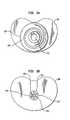
- FIG. 6is a side cross-section view of the preferred embodiment of the present invention, which utilizes a belleville washer of the type shown in FIGS. 4 a and 4 b , showing the plates of FIGS. 6 a and 6 b assembled together.
- the platesinclude substantially flat external face portions 102 , 202 that seat against the opposing bone surfaces.
- the platesare to mate with the bone surfaces in such a way as to not rotate relative thereto. (The plates rotate relative to one another, but not with respect to the bone surfaces with which they are each in contact.)
- the external faces of the platesinclude a porous feature 104 , 204 into which the bone of the vertebral body can grow.
- the most desirable upper and lower plate surface porous featureis a deflectable wire mesh 104 , 204 into which the bone can readily grow, and which mesh will deform to seat into the concave upper and lower bone faces. (Note that this limited fusion of the bone to the base plate does not extend across the intervertebral space.)
- a hole(not shown) can be provided in the upper plate such that the interior of the device may be readily accessed if a need should arise.
- the upper plate 100includes an internal face 103 .
- the lower plate 200includes an internal face 203 that includes a central post 201 which uses out of the internal face 203 at a nearly perpendicular angle.
- the central post 201comprises a plurality of upwardly extending members 202 which mutually define a cylinder 201 having a central axial bore 209 and vertically oriented slots 206 separating each individual member 202 . This conformation permits the cylinder 201 to deflect inward upon the application of a corresponding force and return to an undeflected shape once the force is relieved.
- Each of the upwardly extending members 202comprises a generally uniform radial thickness, thereby mutually defining a constant diameter for the cylinder 201 from its union 204 with the internal face 203 of the lower plate 200 up to a circumferential position 208 near to the uppermost extent 210 thereof.
- the uppermost extent 210 thereofcomprises a discontinuously widened circumference which subsequently tapers radially inwardly from that vertical position to the upper end of the members 202 .
- This discontinuously widened circumferencethereby defines an annular ledge 212 around the cylindrical top section, which ledge 212 tapers inwardly to provide a beveled conformation.
- the portion of the post 201 from the ledge 212 to the upper end of the post 201is referred to herein as the head 207 of the post 201 .
- the central axial bore 209is threaded and is designed to receive a set screw 205 .
- the post 201Prior to the insertion of the set screw 205 , the post 201 can deflect radially inward because of the axial bore 209 and the vertically oriented slots 206 . The insertion of the set screw 205 eliminates the capacity for this deflection.
- the belleville washer 130is a restoring force providing device which comprises a circular shape, having a wide end 139 and a flattened narrow end 133 with a central opening 132 , and which is radially arched in shape.
- the belleville washer 130has a radial convexity (i.e., the height of the washer 130 is not linearly related to the radial distance, but may, for example, be parabolic in shape).
- the restoring force of the belleville washer 130is proportional to the elastic properties of the material.
- the belleville washer 130has a spiral slot 131 formed therein.
- the slot 131extends from a point near the periphery of the wide end 139 of the washer 130 , along an arc that is radially inwardly directed a distance toward a the center of the washer 130 , and terminates at a point near the central opening 132 , preferably where the flatness of the flattened narrow end 133 begins.
- the slot 131extends around the surface of the belleville washer 130 for more than 360 degrees, and most preferably, for 540 degrees as shown.
- Additional configurationsincluding multiple slots, arcs of different lengths and/or arcs that extend for more or less than 360 degrees, can be used to adjust the load bearing and force restoring characteristics of the belleville washer 130 within the scope of the present invention, depending upon the requirements of the patient, and the anatomical requirements of the device.
- the central opening 132 of the belleville washer 130is dimensioned to receive the head 207 of the post 201 of the lower plate 200 described above. More particularly, the diameter of the central opening 132 is greater than the diameter of the cylinder 201 from the union 204 with the internal face 203 of the lower plate 200 up to the ledge 212 , but smaller than the diameter of the head 207 at the ledge 212 . Therefore, the head 207 can be passed through the central opening 132 when the set screw 205 is not in the axial bore 209 , because the slots 206 will allow the head 207 to deflect inward when the head 207 is forced through the central opening 132 .
- the head 207Once the head 207 has passed through the central opening 132 , and consequently the force causing the deflection of the head 207 is relieved, the head 207 will return to its undeflected shape so that the narrow end 133 is seated between the internal face 203 of the lower plate 200 and the ledge 212 of the post 201 . Subsequent introduction of the set screw 205 into the axial bore 209 eliminates the capacity for the head 207 to deflect, ensuring that the head 207 cannot back through the opening 132 without removal of the set screw 205 .
- the length of the post 201 from the internal face 203 of the lower plate 200 to the ledge 212is slightly larger than the thickness of the washer 130 at the narrow end 133 , so that the washer 130 is restricted from angulating with respect to the lower plate 200 but not restricted from rotating with respect to the lower plate 200 .
- Angulation of the plates relative to one anotherwill be possible because of the ability of the washer 130 to deflect under lateral deflection forces and return to its undeflected shape.
- the flat configuration of the narrow end 133 of the washer 130facilitates this preferable fitting of the narrow end 133 between the ledge 212 and the plate 200 .
- FIG. 5 aa top view of the upper plate 100 of FIG. 3 a , with the wide end 139 of the spirally slotted belleville washer 130 of FIGS. 4 a and 4 b rigidly secured thereto, preferably by laser welding the wide end 139 to the upper plate 100 , is shown.
- FIG. 5 bshows a top view of the lower plate 200 of FIG. 3 b , showing the set screw 205 in the axial bore 209 of the post 201 .
- FIG. 6shows the fully assembled preferred embodiment of the present invention.
- the spirally slotted belleville washer 130 of FIGS. 4 a and 4 bis placed with its wide end rigidly fixed against the top plate 100 as shown in FIG. 5 a .
- the head 207 of the post 201 of the lower plate 200is fitted into the central opening 132 of the belleville washer 130 as described above, so that the washer 130 cannot be readily removed therefrom, but can still rotate thereon.
- the devicecan be placed between two vertebral bodies, with the porous features 104 , 204 facilitating bore growth thereinto and securing the plates 100 , 200 to the adjacent bones. Loading of the assembly under normal motion causes the washer 130 to deflect (with the spiral slot 131 enhancing the deflection).
- the spiral slot of the belleville washerallows the washer to compress as the slot narrows under compression loads, only to spring back into its undeflected shape upon the unloading of the spring. Further, the spiral slot allows one side of the washer to compress and the opposite side to expand as the portion of the slot on the one side narrows and the portion of the slot on the opposite side widens under lateral deflection loads, only to spring back into its undeflected shape upon the unloading of the spring.
- some embodiments of the present inventionwill be filled with a highly resilient and biologically inert elastomeric material.
- Suitable materialsmay include hydrophilic monomers such as are used in contact lenses.
- Alternative materialsinclude silicone jellies and collagens such as have been used in cosmetic applications.
Landscapes
- Health & Medical Sciences (AREA)
- Engineering & Computer Science (AREA)
- Biomedical Technology (AREA)
- Neurology (AREA)
- Orthopedic Medicine & Surgery (AREA)
- Cardiology (AREA)
- Oral & Maxillofacial Surgery (AREA)
- Transplantation (AREA)
- Heart & Thoracic Surgery (AREA)
- Vascular Medicine (AREA)
- Life Sciences & Earth Sciences (AREA)
- Animal Behavior & Ethology (AREA)
- General Health & Medical Sciences (AREA)
- Public Health (AREA)
- Veterinary Medicine (AREA)
- Prostheses (AREA)
Abstract
Description
Claims (23)
Priority Applications (2)
| Application Number | Priority Date | Filing Date | Title |
|---|---|---|---|
| US10/040,801US6764515B2 (en) | 2001-02-15 | 2002-01-07 | Intervertebral spacer device utilizing a spirally slotted belleville washer and a rotational mounting |
| US10/859,729US20090177283A9 (en) | 2001-10-01 | 2004-06-03 | Intervertebral spacer device utilizing a spirally slotted belleville washer and a rotational mounting |
Applications Claiming Priority (3)
| Application Number | Priority Date | Filing Date | Title |
|---|---|---|---|
| US78993601A | 2001-02-15 | 2001-02-15 | |
| US09/970,479US6669730B2 (en) | 2001-02-15 | 2001-10-04 | Intervertebral spacer device utilizing a spirally slotted belleville washer having radially extending grooves |
| US10/040,801US6764515B2 (en) | 2001-02-15 | 2002-01-07 | Intervertebral spacer device utilizing a spirally slotted belleville washer and a rotational mounting |
Related Parent Applications (2)
| Application Number | Title | Priority Date | Filing Date |
|---|---|---|---|
| US78993601AContinuation-In-Part | 2001-02-15 | 2001-02-15 | |
| US09/970,479Continuation-In-PartUS6669730B2 (en) | 2001-02-15 | 2001-10-04 | Intervertebral spacer device utilizing a spirally slotted belleville washer having radially extending grooves |
Related Child Applications (1)
| Application Number | Title | Priority Date | Filing Date |
|---|---|---|---|
| US10/859,729ContinuationUS20090177283A9 (en) | 2001-10-01 | 2004-06-03 | Intervertebral spacer device utilizing a spirally slotted belleville washer and a rotational mounting |
Publications (2)
| Publication Number | Publication Date |
|---|---|
| US20020111686A1 US20020111686A1 (en) | 2002-08-15 |
| US6764515B2true US6764515B2 (en) | 2004-07-20 |
Family
ID=32718295
Family Applications (1)
| Application Number | Title | Priority Date | Filing Date |
|---|---|---|---|
| US10/040,801Expired - Fee RelatedUS6764515B2 (en) | 2001-02-15 | 2002-01-07 | Intervertebral spacer device utilizing a spirally slotted belleville washer and a rotational mounting |
Country Status (1)
| Country | Link |
|---|---|
| US (1) | US6764515B2 (en) |
Cited By (88)
| Publication number | Priority date | Publication date | Assignee | Title |
|---|---|---|---|---|
| US20040010318A1 (en)* | 2002-05-15 | 2004-01-15 | Ferree Bret A. | Conformable endplates for artificial disc replacement (ADR) devices and other applications |
| US20040034422A1 (en)* | 2001-07-16 | 2004-02-19 | Errico Joseph P. | Intervertebral spacer device having a circumferentially buried wire mesh endplate attachment device |
| US20040098130A1 (en)* | 2001-10-18 | 2004-05-20 | Ralph James D. | Intervertebral spacer device having a multi-pronged domed spring |
| US20040220671A1 (en)* | 2001-10-01 | 2004-11-04 | Ralph James D | Intervertebral spacer device utilizing a spirally slotted belleville washer and a rotational mounting |
| US20050060036A1 (en)* | 2003-05-21 | 2005-03-17 | Robert Schultz | Spinal column implant |
| US20050071007A1 (en)* | 2003-09-30 | 2005-03-31 | Malek Michel H. | Intervertebral disc prosthesis |
| US6986789B2 (en) | 2003-08-22 | 2006-01-17 | Aesculap Ag & Co. Kg | Intervertebral implant |
| US20060095132A1 (en)* | 2004-10-29 | 2006-05-04 | X-Spine Systems, Inc. | Prosthetic implant and method |
| US20060149378A1 (en)* | 2004-11-24 | 2006-07-06 | Brad Chase | Articulating spinal disc prosthetic |
| US20060217809A1 (en)* | 2005-03-24 | 2006-09-28 | Accin Corporation | Intervertebral disc replacement device |
| US20060293752A1 (en)* | 2005-06-27 | 2006-12-28 | Missoum Moumene | Intervertebral disc prosthesis and associated methods |
| US7198644B2 (en) | 2003-07-08 | 2007-04-03 | Aesculap Ag & Co. Kg | Intervertebral implant |
| US20070162133A1 (en)* | 2004-03-02 | 2007-07-12 | Robert Doubler | Concentric interior insert ball and dual socket joint |
| US20070191958A1 (en)* | 2006-02-15 | 2007-08-16 | Abdou M S | Devices and Methods for Inter-Vertebral Orthopedic Device Placement |
| US20070282448A1 (en)* | 2006-05-26 | 2007-12-06 | Abdou M S | Inter-Vertebral Disc Motion Devices and Methods of Use |
| US7326250B2 (en) | 2001-05-04 | 2008-02-05 | Ldr Medical | Intervertebral disc prosthesis and fitting tools |
| US20080114453A1 (en)* | 2006-11-13 | 2008-05-15 | Warsaw Orthopedic, Inc. | Intervertebral prosthetic devices and surgical methods |
| US20080306597A1 (en)* | 2007-01-19 | 2008-12-11 | Pietro Filippo Adamo | Invertebral disc prosthesis for the cervical spine in the dog |
| US7491239B2 (en) | 2005-02-23 | 2009-02-17 | Joint Synergy, Llc | Interior insert ball and dual socket joint |
| US7494508B2 (en) | 2004-04-28 | 2009-02-24 | Ldr Medical | Intervertebral disc prosthesis |
| US20090105833A1 (en)* | 2007-10-22 | 2009-04-23 | Spinalmotion, Inc. | Method and Spacer Device for Spanning a Space Formed upon Removal of an Intervertebral Disc |
| US20090138083A1 (en)* | 2006-09-14 | 2009-05-28 | Ashok Biyani | Variable height vertebral body replacement implant |
| US7549995B2 (en) | 2003-07-08 | 2009-06-23 | Aesculap Ag | Surgical instrument for handling an implant |
| US7585325B2 (en) | 2004-06-16 | 2009-09-08 | Aesculap Ag | Intervertebral implant |
| US20090240335A1 (en)* | 2008-03-24 | 2009-09-24 | Arcenio Gregory B | Expandable Devices for Emplacement in Body Parts and Methods Associated Therewith |
| US7632282B2 (en) | 2005-06-29 | 2009-12-15 | Ldr Medical | Instrumentation and methods for inserting an intervertebral disc prosthesis |
| US7655045B2 (en) | 2003-05-06 | 2010-02-02 | Aesculap Implant Systems, Llc | Artificial intervertebral disc |
| US7674296B2 (en) | 2005-04-21 | 2010-03-09 | Globus Medical, Inc. | Expandable vertebral prosthesis |
| US7682396B2 (en) | 2002-11-05 | 2010-03-23 | Ldr Medical | Intervertebral disc prosthesis |
| US7695516B2 (en) | 2004-12-22 | 2010-04-13 | Ldr Medical | Intervertebral disc prosthesis |
| US7713302B2 (en) | 2001-10-01 | 2010-05-11 | Spinecore, Inc. | Intervertebral spacer device utilizing a spirally slotted belleville washer having radially spaced concentric grooves |
| US20100160964A1 (en)* | 2008-12-18 | 2010-06-24 | Malek Michel H | Flexible spinal stabilization system |
| US7771478B2 (en) | 2003-04-04 | 2010-08-10 | Theken Spine, Llc | Artificial disc prosthesis |
| US7799081B2 (en) | 2004-09-14 | 2010-09-21 | Aeolin, Llc | System and method for spinal fusion |
| US7799056B2 (en) | 2007-12-31 | 2010-09-21 | Warsaw Orthopedic, Inc. | Bone fusion device and methods |
| US20100241175A1 (en)* | 2009-03-20 | 2010-09-23 | Spinal USA LLC | Pedicle screws and methods of using the same |
| US7815648B2 (en) | 2004-06-02 | 2010-10-19 | Facet Solutions, Inc | Surgical measurement systems and methods |
| US7832409B2 (en) | 2003-05-06 | 2010-11-16 | Aesculap Implant Systems, Llc | Method of inserting an artificial intervertebral disc |
| US7842088B2 (en) | 2005-09-23 | 2010-11-30 | Ldr Medical | Intervertebral disc prosthesis |
| US7914560B2 (en) | 2004-02-17 | 2011-03-29 | Gmedelaware 2 Llc | Spinal facet implant with spherical implant apposition surface and bone bed and methods of use |
| US7935133B2 (en) | 2008-02-08 | 2011-05-03 | Mmsn Limited Partnership | Interlaminar hook |
| US7985231B2 (en) | 2007-12-31 | 2011-07-26 | Kyphon Sarl | Bone fusion device and methods |
| US8002834B2 (en) | 2004-07-30 | 2011-08-23 | Spinalmotion, Inc. | Intervertebral prosthetic disc with metallic core |
| US8016886B2 (en) | 2006-07-18 | 2011-09-13 | Altus Partners, Llc | Intervertebral disc replacement device |
| US8083797B2 (en) | 2005-02-04 | 2011-12-27 | Spinalmotion, Inc. | Intervertebral prosthetic disc with shock absorption |
| US8090428B2 (en) | 2003-01-31 | 2012-01-03 | Spinalmotion, Inc. | Spinal midline indicator |
| US8092538B2 (en) | 2003-05-27 | 2012-01-10 | Spinalmotion, Inc. | Intervertebral prosthetic disc |
| US8092539B2 (en) | 2001-10-01 | 2012-01-10 | Spinecore, Inc. | Intervertebral spacer device having a belleville washer with concentric grooves |
| US8092540B2 (en) | 2002-09-18 | 2012-01-10 | Synthes Usa, Llc | Implant comprising a two-piece joint |
| US8187304B2 (en) | 2008-11-10 | 2012-05-29 | Malek Michel H | Facet fusion system |
| US8206418B2 (en) | 2007-01-10 | 2012-06-26 | Gmedelaware 2 Llc | System and method for facet joint replacement with detachable coupler |
| US8206449B2 (en) | 2008-07-17 | 2012-06-26 | Spinalmotion, Inc. | Artificial intervertebral disc placement system |
| US8206447B2 (en) | 2004-08-06 | 2012-06-26 | Spinalmotion, Inc. | Methods and apparatus for intervertebral disc prosthesis insertion |
| US8282683B2 (en) | 2010-04-12 | 2012-10-09 | Globus Medical, Inc. | Expandable vertebral implant |
| US8303660B1 (en) | 2006-04-22 | 2012-11-06 | Samy Abdou | Inter-vertebral disc prosthesis with variable rotational stop and methods of use |
| US8343219B2 (en) | 2007-06-08 | 2013-01-01 | Ldr Medical | Intersomatic cage, intervertebral prosthesis, anchoring device and implantation instruments |
| US8357167B2 (en) | 2001-07-16 | 2013-01-22 | Spinecore, Inc. | Artificial intervertebral disc trials with baseplates having inward tool engagement holes |
| US8465546B2 (en) | 2007-02-16 | 2013-06-18 | Ldr Medical | Intervertebral disc prosthesis insertion assemblies |
| US8486113B2 (en) | 2003-11-25 | 2013-07-16 | Michel H. Malek | Spinal stabilization systems |
| US8486147B2 (en) | 2006-04-12 | 2013-07-16 | Spinalmotion, Inc. | Posterior spinal device and method |
| US8506631B2 (en) | 2007-08-09 | 2013-08-13 | Spinalmotion, Inc. | Customized intervertebral prosthetic disc with shock absorption |
| US8617214B2 (en) | 2008-01-07 | 2013-12-31 | Mmsn Limited Partnership | Spinal tension band |
| US8721723B2 (en) | 2009-01-12 | 2014-05-13 | Globus Medical, Inc. | Expandable vertebral prosthesis |
| US8764833B2 (en) | 2008-03-11 | 2014-07-01 | Spinalmotion, Inc. | Artificial intervertebral disc with lower height |
| US8777994B2 (en) | 2004-06-02 | 2014-07-15 | Gmedelaware 2 Llc | System and method for multiple level facet joint arthroplasty and fusion |
| US8845730B2 (en) | 2008-07-18 | 2014-09-30 | Simplify Medical, Inc. | Posterior prosthetic intervertebral disc |
| US8858635B2 (en) | 2004-02-04 | 2014-10-14 | Ldr Medical | Intervertebral disc prosthesis |
| US9011544B2 (en) | 2008-05-05 | 2015-04-21 | Simplify Medical, Inc. | Polyaryletherketone artificial intervertebral disc |
| US9034038B2 (en) | 2008-04-11 | 2015-05-19 | Spinalmotion, Inc. | Motion limiting insert for an artificial intervertebral disc |
| US9220603B2 (en) | 2008-07-02 | 2015-12-29 | Simplify Medical, Inc. | Limited motion prosthetic intervertebral disc |
| US9265618B2 (en) | 2005-11-30 | 2016-02-23 | Ldr Medical | Intervertebral disc prosthesis and instrumentation for insertion of the prosthesis between the vertebrae |
| US9301787B2 (en) | 2010-09-27 | 2016-04-05 | Mmsn Limited Partnership | Medical apparatus and method for spinal surgery |
| US9402745B2 (en) | 2003-01-31 | 2016-08-02 | Simplify Medical, Inc. | Intervertebral prosthesis placement instrument |
| US9655741B2 (en) | 2003-05-27 | 2017-05-23 | Simplify Medical Pty Ltd | Prosthetic disc for intervertebral insertion |
| US9707091B2 (en) | 2010-04-12 | 2017-07-18 | Globus Medical, Inc. | Expandable vertebral implant |
| US9913735B2 (en) | 2010-04-12 | 2018-03-13 | Globus Medical, Inc. | Angling inserter tool for expandable vertebral implant |
| US10130489B2 (en) | 2010-04-12 | 2018-11-20 | Globus Medical, Inc. | Expandable vertebral implant |
| US10543107B2 (en) | 2009-12-07 | 2020-01-28 | Samy Abdou | Devices and methods for minimally invasive spinal stabilization and instrumentation |
| US10548740B1 (en) | 2016-10-25 | 2020-02-04 | Samy Abdou | Devices and methods for vertebral bone realignment |
| US10575961B1 (en) | 2011-09-23 | 2020-03-03 | Samy Abdou | Spinal fixation devices and methods of use |
| US10603185B2 (en) | 2004-02-04 | 2020-03-31 | Ldr Medical | Intervertebral disc prosthesis |
| US10695105B2 (en) | 2012-08-28 | 2020-06-30 | Samy Abdou | Spinal fixation devices and methods of use |
| US10857003B1 (en) | 2015-10-14 | 2020-12-08 | Samy Abdou | Devices and methods for vertebral stabilization |
| US10918498B2 (en) | 2004-11-24 | 2021-02-16 | Samy Abdou | Devices and methods for inter-vertebral orthopedic device placement |
| US10973648B1 (en) | 2016-10-25 | 2021-04-13 | Samy Abdou | Devices and methods for vertebral bone realignment |
| US11006982B2 (en) | 2012-02-22 | 2021-05-18 | Samy Abdou | Spinous process fixation devices and methods of use |
| US11173040B2 (en) | 2012-10-22 | 2021-11-16 | Cogent Spine, LLC | Devices and methods for spinal stabilization and instrumentation |
| US11179248B2 (en) | 2018-10-02 | 2021-11-23 | Samy Abdou | Devices and methods for spinal implantation |
Families Citing this family (24)
| Publication number | Priority date | Publication date | Assignee | Title |
|---|---|---|---|---|
| US8323341B2 (en) | 2007-09-07 | 2012-12-04 | Intrinsic Therapeutics, Inc. | Impaction grafting for vertebral fusion |
| US6669730B2 (en) | 2001-02-15 | 2003-12-30 | Spinecore, Inc. | Intervertebral spacer device utilizing a spirally slotted belleville washer having radially extending grooves |
| US6471725B1 (en)* | 2001-07-16 | 2002-10-29 | Third Millenium Engineering, Llc | Porous intervertebral distraction spacers |
| US7722675B2 (en)* | 2001-07-16 | 2010-05-25 | Spinecore, Inc. | Instruments for reorienting vertebral bones for the treatment of scoliosis |
| US7208014B2 (en)* | 2001-10-01 | 2007-04-24 | Spinecore, Inc. | Intervertebral spacer device utilizing a belleville washer having radially extending grooves |
| US20080027548A9 (en) | 2002-04-12 | 2008-01-31 | Ferree Bret A | Spacerless artificial disc replacements |
| US8038713B2 (en) | 2002-04-23 | 2011-10-18 | Spinecore, Inc. | Two-component artificial disc replacements |
| CA2495404C (en) | 2002-08-15 | 2011-05-03 | Justin K. Coppes | Intervertebral disc implant |
| EP1542626B1 (en) | 2002-08-15 | 2012-09-26 | Synthes GmbH | Controlled artificial intervertebral disc implant |
| AU2004212942A1 (en) | 2003-02-14 | 2004-09-02 | Depuy Spine, Inc. | In-situ formed intervertebral fusion device |
| US6908484B2 (en) | 2003-03-06 | 2005-06-21 | Spinecore, Inc. | Cervical disc replacement |
| US20040267367A1 (en)* | 2003-06-30 | 2004-12-30 | Depuy Acromed, Inc | Intervertebral implant with conformable endplate |
| US7713304B2 (en) | 2003-07-31 | 2010-05-11 | Globus Medical, Inc. | Transforaminal prosthetic spinal disc replacement |
| US7621956B2 (en)* | 2003-07-31 | 2009-11-24 | Globus Medical, Inc. | Prosthetic spinal disc replacement |
| US7811329B2 (en) | 2003-07-31 | 2010-10-12 | Globus Medical | Transforaminal prosthetic spinal disc replacement and methods thereof |
| US8123757B2 (en)* | 2003-12-31 | 2012-02-28 | Depuy Spine, Inc. | Inserter instrument and implant clip |
| US7867279B2 (en)* | 2006-01-23 | 2011-01-11 | Depuy Spine, Inc. | Intervertebral disc prosthesis |
| US7766967B2 (en)* | 2006-04-06 | 2010-08-03 | Warsaw Orthopedic Inc. | Intervertebral disc nucleus replacement implants and methods |
| US8579910B2 (en) | 2007-05-18 | 2013-11-12 | DePuy Synthes Products, LLC | Insertion blade assembly and method of use |
| US8906033B2 (en) | 2009-03-30 | 2014-12-09 | DePuy Synthes Products, LLC | Cervical motion disc inserter |
| US8277509B2 (en) | 2009-12-07 | 2012-10-02 | Globus Medical, Inc. | Transforaminal prosthetic spinal disc apparatus |
| US9017410B2 (en) | 2011-10-26 | 2015-04-28 | Globus Medical, Inc. | Artificial discs |
| US9198770B2 (en) | 2013-07-31 | 2015-12-01 | Globus Medical, Inc. | Artificial disc devices and related methods of use |
| CN111568610B (en)* | 2020-05-29 | 2022-12-27 | 四川大学华西医院 | Lateral front approach cervical interbody fusion cage and matched bone grafting tool |
Citations (22)
| Publication number | Priority date | Publication date | Assignee | Title |
|---|---|---|---|---|
| US4917704A (en)* | 1987-07-09 | 1990-04-17 | Sulzer Brothers Limited | Intervertebral prosthesis |
| US5458642A (en) | 1994-01-18 | 1995-10-17 | Beer; John C. | Synthetic intervertebral disc |
| US5556431A (en) | 1992-03-13 | 1996-09-17 | B+E,Uml U+Ee Ttner-Janz; Karin | Intervertebral disc endoprosthesis |
| US5562738A (en) | 1992-01-06 | 1996-10-08 | Danek Medical, Inc. | Intervertebral disk arthroplasty device |
| US5674296A (en) | 1994-11-14 | 1997-10-07 | Spinal Dynamics Corporation | Human spinal disc prosthesis |
| US5676702A (en) | 1994-12-16 | 1997-10-14 | Tornier S.A. | Elastic disc prosthesis |
| US5676701A (en) | 1993-01-14 | 1997-10-14 | Smith & Nephew, Inc. | Low wear artificial spinal disc |
| US5683465A (en) | 1996-03-18 | 1997-11-04 | Shinn; Gary Lee | Artificial intervertebral disk prosthesis |
| US5755796A (en) | 1996-06-06 | 1998-05-26 | Ibo; Ivo | Prosthesis of the cervical intervertebralis disk |
| US5827328A (en) | 1996-11-22 | 1998-10-27 | Buttermann; Glenn R. | Intervertebral prosthetic device |
| US5888226A (en) | 1997-11-12 | 1999-03-30 | Rogozinski; Chaim | Intervertebral prosthetic disc |
| US5895428A (en) | 1996-11-01 | 1999-04-20 | Berry; Don | Load bearing spinal joint implant |
| US5899941A (en) | 1997-12-09 | 1999-05-04 | Chubu Bearing Kabushiki Kaisha | Artificial intervertebral disk |
| US5989291A (en) | 1998-02-26 | 1999-11-23 | Third Millennium Engineering, Llc | Intervertebral spacer device |
| US6019792A (en) | 1998-04-23 | 2000-02-01 | Cauthen Research Group, Inc. | Articulating spinal implant |
| US6039763A (en) | 1998-10-27 | 2000-03-21 | Disc Replacement Technologies, Inc. | Articulating spinal disc prosthesis |
| US6063121A (en) | 1998-07-29 | 2000-05-16 | Xavier; Ravi | Vertebral body prosthesis |
| US6113637A (en) | 1998-10-22 | 2000-09-05 | Sofamor Danek Holdings, Inc. | Artificial intervertebral joint permitting translational and rotational motion |
| US6136031A (en) | 1998-06-17 | 2000-10-24 | Surgical Dynamics, Inc. | Artificial intervertebral disc |
| US6146421A (en) | 1997-08-04 | 2000-11-14 | Gordon, Maya, Roberts And Thomas, Number 1, Llc | Multiple axis intervertebral prosthesis |
| US6179874B1 (en) | 1998-04-23 | 2001-01-30 | Cauthen Research Group, Inc. | Articulating spinal implant |
| US6228118B1 (en) | 1997-08-04 | 2001-05-08 | Gordon, Maya, Roberts And Thomas, Number 1, Llc | Multiple axis intervertebral prosthesis |
- 2002
- 2002-01-07USUS10/040,801patent/US6764515B2/ennot_activeExpired - Fee Related
Patent Citations (25)
| Publication number | Priority date | Publication date | Assignee | Title |
|---|---|---|---|---|
| US4917704A (en)* | 1987-07-09 | 1990-04-17 | Sulzer Brothers Limited | Intervertebral prosthesis |
| US5562738A (en) | 1992-01-06 | 1996-10-08 | Danek Medical, Inc. | Intervertebral disk arthroplasty device |
| US5556431A (en) | 1992-03-13 | 1996-09-17 | B+E,Uml U+Ee Ttner-Janz; Karin | Intervertebral disc endoprosthesis |
| US5676701A (en) | 1993-01-14 | 1997-10-14 | Smith & Nephew, Inc. | Low wear artificial spinal disc |
| US5458642A (en) | 1994-01-18 | 1995-10-17 | Beer; John C. | Synthetic intervertebral disc |
| US5674296A (en) | 1994-11-14 | 1997-10-07 | Spinal Dynamics Corporation | Human spinal disc prosthesis |
| US6156067A (en) | 1994-11-14 | 2000-12-05 | Spinal Dynamics Corporation | Human spinal disc prosthesis |
| US5865846A (en) | 1994-11-14 | 1999-02-02 | Bryan; Vincent | Human spinal disc prosthesis |
| US6001130A (en) | 1994-11-14 | 1999-12-14 | Bryan; Vincent | Human spinal disc prosthesis with hinges |
| US5676702A (en) | 1994-12-16 | 1997-10-14 | Tornier S.A. | Elastic disc prosthesis |
| US5683465A (en) | 1996-03-18 | 1997-11-04 | Shinn; Gary Lee | Artificial intervertebral disk prosthesis |
| US5755796A (en) | 1996-06-06 | 1998-05-26 | Ibo; Ivo | Prosthesis of the cervical intervertebralis disk |
| US5895428A (en) | 1996-11-01 | 1999-04-20 | Berry; Don | Load bearing spinal joint implant |
| US5827328A (en) | 1996-11-22 | 1998-10-27 | Buttermann; Glenn R. | Intervertebral prosthetic device |
| US6146421A (en) | 1997-08-04 | 2000-11-14 | Gordon, Maya, Roberts And Thomas, Number 1, Llc | Multiple axis intervertebral prosthesis |
| US6228118B1 (en) | 1997-08-04 | 2001-05-08 | Gordon, Maya, Roberts And Thomas, Number 1, Llc | Multiple axis intervertebral prosthesis |
| US5888226A (en) | 1997-11-12 | 1999-03-30 | Rogozinski; Chaim | Intervertebral prosthetic disc |
| US5899941A (en) | 1997-12-09 | 1999-05-04 | Chubu Bearing Kabushiki Kaisha | Artificial intervertebral disk |
| US5989291A (en) | 1998-02-26 | 1999-11-23 | Third Millennium Engineering, Llc | Intervertebral spacer device |
| US6019792A (en) | 1998-04-23 | 2000-02-01 | Cauthen Research Group, Inc. | Articulating spinal implant |
| US6179874B1 (en) | 1998-04-23 | 2001-01-30 | Cauthen Research Group, Inc. | Articulating spinal implant |
| US6136031A (en) | 1998-06-17 | 2000-10-24 | Surgical Dynamics, Inc. | Artificial intervertebral disc |
| US6063121A (en) | 1998-07-29 | 2000-05-16 | Xavier; Ravi | Vertebral body prosthesis |
| US6113637A (en) | 1998-10-22 | 2000-09-05 | Sofamor Danek Holdings, Inc. | Artificial intervertebral joint permitting translational and rotational motion |
| US6039763A (en) | 1998-10-27 | 2000-03-21 | Disc Replacement Technologies, Inc. | Articulating spinal disc prosthesis |
Cited By (210)
| Publication number | Priority date | Publication date | Assignee | Title |
|---|---|---|---|---|
| US7326250B2 (en) | 2001-05-04 | 2008-02-05 | Ldr Medical | Intervertebral disc prosthesis and fitting tools |
| US9333095B2 (en) | 2001-05-04 | 2016-05-10 | Ldr Medical | Intervertebral disc prosthesis, surgical methods, and fitting tools |
| US20040034422A1 (en)* | 2001-07-16 | 2004-02-19 | Errico Joseph P. | Intervertebral spacer device having a circumferentially buried wire mesh endplate attachment device |
| US8357167B2 (en) | 2001-07-16 | 2013-01-22 | Spinecore, Inc. | Artificial intervertebral disc trials with baseplates having inward tool engagement holes |
| US8092539B2 (en) | 2001-10-01 | 2012-01-10 | Spinecore, Inc. | Intervertebral spacer device having a belleville washer with concentric grooves |
| US7713302B2 (en) | 2001-10-01 | 2010-05-11 | Spinecore, Inc. | Intervertebral spacer device utilizing a spirally slotted belleville washer having radially spaced concentric grooves |
| US20040220671A1 (en)* | 2001-10-01 | 2004-11-04 | Ralph James D | Intervertebral spacer device utilizing a spirally slotted belleville washer and a rotational mounting |
| US20090177283A9 (en)* | 2001-10-01 | 2009-07-09 | Ralph James D | Intervertebral spacer device utilizing a spirally slotted belleville washer and a rotational mounting |
| US20040111156A1 (en)* | 2001-10-18 | 2004-06-10 | Ralph James D. | Intervertebral spacer device having a domed arch shaped spring |
| US20050182491A1 (en)* | 2001-10-18 | 2005-08-18 | Spinecore, Inc. | Intervertebral spacer device having a domed arch shaped spring |
| US7014658B2 (en)* | 2001-10-18 | 2006-03-21 | Spinecore, Inc. | Intervertebral spacer device having a multi-pronged domed spring |
| US8029568B2 (en) | 2001-10-18 | 2011-10-04 | Spinecore, Inc. | Intervertebral spacer device having a slotted partial circular domed arch strip spring |
| US6869446B2 (en)* | 2001-10-18 | 2005-03-22 | Spinecore, Inc. | Intervertebral spacer device having a domed arch shaped spring |
| US20040098130A1 (en)* | 2001-10-18 | 2004-05-20 | Ralph James D. | Intervertebral spacer device having a multi-pronged domed spring |
| US7141070B2 (en) | 2001-10-18 | 2006-11-28 | Spinecore, Inc. | Intervertebral spacer device having a domed arch shaped spring |
| US20040010318A1 (en)* | 2002-05-15 | 2004-01-15 | Ferree Bret A. | Conformable endplates for artificial disc replacement (ADR) devices and other applications |
| US8092540B2 (en) | 2002-09-18 | 2012-01-10 | Synthes Usa, Llc | Implant comprising a two-piece joint |
| US7682396B2 (en) | 2002-11-05 | 2010-03-23 | Ldr Medical | Intervertebral disc prosthesis |
| US8267999B2 (en) | 2002-11-05 | 2012-09-18 | Ldr Medical | Intervertebral disc prosthesis |
| US8090428B2 (en) | 2003-01-31 | 2012-01-03 | Spinalmotion, Inc. | Spinal midline indicator |
| US10105131B2 (en) | 2003-01-31 | 2018-10-23 | Simplify Medical Pty Ltd | Intervertebral prosthesis placement instrument |
| US9402745B2 (en) | 2003-01-31 | 2016-08-02 | Simplify Medical, Inc. | Intervertebral prosthesis placement instrument |
| US7771478B2 (en) | 2003-04-04 | 2010-08-10 | Theken Spine, Llc | Artificial disc prosthesis |
| US7766966B2 (en) | 2003-05-06 | 2010-08-03 | Aesculap Implant Systems, Llc | Artificial intervertebral disc |
| US7832409B2 (en) | 2003-05-06 | 2010-11-16 | Aesculap Implant Systems, Llc | Method of inserting an artificial intervertebral disc |
| US7655045B2 (en) | 2003-05-06 | 2010-02-02 | Aesculap Implant Systems, Llc | Artificial intervertebral disc |
| US20050060036A1 (en)* | 2003-05-21 | 2005-03-17 | Robert Schultz | Spinal column implant |
| US10357376B2 (en) | 2003-05-27 | 2019-07-23 | Simplify Medical Pty Ltd | Intervertebral prosthetic disc |
| US10342670B2 (en) | 2003-05-27 | 2019-07-09 | Simplify Medical Pty Ltd | Intervertebral prosthetic disc |
| US8444695B2 (en) | 2003-05-27 | 2013-05-21 | Spinalmotion, Inc. | Prosthetic disc for intervertebral insertion |
| US10052211B2 (en) | 2003-05-27 | 2018-08-21 | Simplify Medical Pty Ltd. | Prosthetic disc for intervertebral insertion |
| US8092538B2 (en) | 2003-05-27 | 2012-01-10 | Spinalmotion, Inc. | Intervertebral prosthetic disc |
| US8454698B2 (en) | 2003-05-27 | 2013-06-04 | Spinalmotion, Inc. | Prosthetic disc for intervertebral insertion |
| US11771565B2 (en) | 2003-05-27 | 2023-10-03 | Simplify Medical Pty Ltd | Prosthetic disc for intervertebral insertion |
| US10342671B2 (en) | 2003-05-27 | 2019-07-09 | Simplify Medical Pty Ltd | Intervertebral prosthetic disc |
| US9439774B2 (en) | 2003-05-27 | 2016-09-13 | Simplify Medical Pty Ltd | Intervertebral prosthetic disc |
| US9107762B2 (en) | 2003-05-27 | 2015-08-18 | Spinalmotion, Inc. | Intervertebral prosthetic disc with metallic core |
| US11376130B2 (en) | 2003-05-27 | 2022-07-05 | Simplify Medical Pty Ltd | Intervertebral prosthetic disc |
| US8771356B2 (en) | 2003-05-27 | 2014-07-08 | Spinalmotion, Inc. | Intervertebral prosthetic disc |
| US9655741B2 (en) | 2003-05-27 | 2017-05-23 | Simplify Medical Pty Ltd | Prosthetic disc for intervertebral insertion |
| US10219911B2 (en) | 2003-05-27 | 2019-03-05 | Simplify Medical Pty Ltd | Prosthetic disc for intervertebral insertion |
| US9788965B2 (en) | 2003-05-27 | 2017-10-17 | Simplify Medical Pty Ltd | Prosthetic disc for intervertebral insertion |
| USRE46802E1 (en) | 2003-05-27 | 2018-04-24 | Simplify Medical Pty Limited | Intervertebral prosthetic disc with metallic core |
| US8845729B2 (en) | 2003-05-27 | 2014-09-30 | Simplify Medical, Inc. | Prosthetic disc for intervertebral insertion |
| US8974533B2 (en) | 2003-05-27 | 2015-03-10 | Simplify Medical, Inc. | Prosthetic disc for intervertebral insertion |
| US7549995B2 (en) | 2003-07-08 | 2009-06-23 | Aesculap Ag | Surgical instrument for handling an implant |
| US7198644B2 (en) | 2003-07-08 | 2007-04-03 | Aesculap Ag & Co. Kg | Intervertebral implant |
| US6986789B2 (en) | 2003-08-22 | 2006-01-17 | Aesculap Ag & Co. Kg | Intervertebral implant |
| US7402176B2 (en) | 2003-09-30 | 2008-07-22 | Malek Michel H | Intervertebral disc prosthesis |
| US20050071007A1 (en)* | 2003-09-30 | 2005-03-31 | Malek Michel H. | Intervertebral disc prosthesis |
| US20070185577A1 (en)* | 2003-09-30 | 2007-08-09 | Malek Michel H | Intervertebral disc prosthesis |
| US7255714B2 (en)* | 2003-09-30 | 2007-08-14 | Michel H. Malek | Vertically adjustable intervertebral disc prosthesis |
| US8097038B2 (en) | 2003-09-30 | 2012-01-17 | Mmsn Limited Partnership | Prosthetic vertebral assembly |
| US8486113B2 (en) | 2003-11-25 | 2013-07-16 | Michel H. Malek | Spinal stabilization systems |
| US11957598B2 (en) | 2004-02-04 | 2024-04-16 | Ldr Medical | Intervertebral disc prosthesis |
| US8858635B2 (en) | 2004-02-04 | 2014-10-14 | Ldr Medical | Intervertebral disc prosthesis |
| US10603185B2 (en) | 2004-02-04 | 2020-03-31 | Ldr Medical | Intervertebral disc prosthesis |
| US7914560B2 (en) | 2004-02-17 | 2011-03-29 | Gmedelaware 2 Llc | Spinal facet implant with spherical implant apposition surface and bone bed and methods of use |
| US7998178B2 (en) | 2004-02-17 | 2011-08-16 | Gmedelaware 2 Llc | Linked bilateral spinal facet implants and methods of use |
| US7998177B2 (en) | 2004-02-17 | 2011-08-16 | Gmedelaware 2 Llc | Linked bilateral spinal facet implants and methods of use |
| US8906063B2 (en) | 2004-02-17 | 2014-12-09 | Gmedelaware 2 Llc | Spinal facet joint implant |
| US20070162133A1 (en)* | 2004-03-02 | 2007-07-12 | Robert Doubler | Concentric interior insert ball and dual socket joint |
| US8002835B2 (en) | 2004-04-28 | 2011-08-23 | Ldr Medical | Intervertebral disc prosthesis |
| US7494508B2 (en) | 2004-04-28 | 2009-02-24 | Ldr Medical | Intervertebral disc prosthesis |
| US7815648B2 (en) | 2004-06-02 | 2010-10-19 | Facet Solutions, Inc | Surgical measurement systems and methods |
| US8777994B2 (en) | 2004-06-02 | 2014-07-15 | Gmedelaware 2 Llc | System and method for multiple level facet joint arthroplasty and fusion |
| US7585325B2 (en) | 2004-06-16 | 2009-09-08 | Aesculap Ag | Intervertebral implant |
| US8062371B2 (en) | 2004-07-30 | 2011-11-22 | Spinalmotion, Inc. | Intervertebral prosthetic disc with metallic core |
| US8002834B2 (en) | 2004-07-30 | 2011-08-23 | Spinalmotion, Inc. | Intervertebral prosthetic disc with metallic core |
| US11857438B2 (en) | 2004-08-06 | 2024-01-02 | Simplify Medical Pty Ltd | Methods and apparatus for intervertebral disc prosthesis insertion |
| US8974531B2 (en) | 2004-08-06 | 2015-03-10 | Simplify Medical, Inc. | Methods and apparatus for intervertebral disc prosthesis insertion |
| US10085853B2 (en) | 2004-08-06 | 2018-10-02 | Simplify Medical Pty Ltd | Methods and apparatus for intervertebral disc prosthesis insertion |
| US9956091B2 (en) | 2004-08-06 | 2018-05-01 | Simplify Medical Pty Ltd | Methods and apparatus for intervertebral disc prosthesis insertion |
| US10130494B2 (en) | 2004-08-06 | 2018-11-20 | Simplify Medical Pty Ltd. | Methods and apparatus for intervertebral disc prosthesis insertion |
| US8206447B2 (en) | 2004-08-06 | 2012-06-26 | Spinalmotion, Inc. | Methods and apparatus for intervertebral disc prosthesis insertion |
| US9839532B2 (en) | 2004-08-06 | 2017-12-12 | Simplify Medical Pty Ltd | Methods and apparatus for intervertebral disc prosthesis insertion |
| US10888437B2 (en) | 2004-08-06 | 2021-01-12 | Simplify Medical Pty Ltd | Methods and apparatus for intervertebral disc prosthesis insertion |
| US7799081B2 (en) | 2004-09-14 | 2010-09-21 | Aeolin, Llc | System and method for spinal fusion |
| US8562683B2 (en) | 2004-09-14 | 2013-10-22 | Aeolin Llc | System and method for spinal fusion |
| US7566346B2 (en) | 2004-10-29 | 2009-07-28 | X-Spine Systems, Inc. | Prosthetic implant and method |
| US20060095132A1 (en)* | 2004-10-29 | 2006-05-04 | X-Spine Systems, Inc. | Prosthetic implant and method |
| US11992423B2 (en) | 2004-11-24 | 2024-05-28 | Samy Abdou | Devices and methods for inter-vertebral orthopedic device placement |
| US10918498B2 (en) | 2004-11-24 | 2021-02-16 | Samy Abdou | Devices and methods for inter-vertebral orthopedic device placement |
| US20060149378A1 (en)* | 2004-11-24 | 2006-07-06 | Brad Chase | Articulating spinal disc prosthetic |
| US11096799B2 (en) | 2004-11-24 | 2021-08-24 | Samy Abdou | Devices and methods for inter-vertebral orthopedic device placement |
| US10226355B2 (en) | 2004-12-22 | 2019-03-12 | Ldr Medical | Intervertebral disc prosthesis |
| US7695516B2 (en) | 2004-12-22 | 2010-04-13 | Ldr Medical | Intervertebral disc prosthesis |
| US8257439B2 (en) | 2004-12-22 | 2012-09-04 | Ldr Medical | Intervertebral disc prosthesis |
| US8398712B2 (en) | 2005-02-04 | 2013-03-19 | Spinalmotion, Inc. | Intervertebral prosthetic disc with shock absorption |
| US8083797B2 (en) | 2005-02-04 | 2011-12-27 | Spinalmotion, Inc. | Intervertebral prosthetic disc with shock absorption |
| US7491239B2 (en) | 2005-02-23 | 2009-02-17 | Joint Synergy, Llc | Interior insert ball and dual socket joint |
| US20060217809A1 (en)* | 2005-03-24 | 2006-09-28 | Accin Corporation | Intervertebral disc replacement device |
| US7753957B2 (en) | 2005-03-24 | 2010-07-13 | Accelerated Innovation, Llc | Ball and Socket intervertebral disc replacement device with keyed surfaces assembly |
| US7674296B2 (en) | 2005-04-21 | 2010-03-09 | Globus Medical, Inc. | Expandable vertebral prosthesis |
| US20060293752A1 (en)* | 2005-06-27 | 2006-12-28 | Missoum Moumene | Intervertebral disc prosthesis and associated methods |
| US8439931B2 (en) | 2005-06-29 | 2013-05-14 | Ldr Medical | Instrumentation and methods for inserting an intervertebral disc prosthesis |
| US10350088B2 (en) | 2005-06-29 | 2019-07-16 | Ldr Medical | Instrumentation and methods for inserting an intervertebral disc prosthesis |
| US7632282B2 (en) | 2005-06-29 | 2009-12-15 | Ldr Medical | Instrumentation and methods for inserting an intervertebral disc prosthesis |
| US7842088B2 (en) | 2005-09-23 | 2010-11-30 | Ldr Medical | Intervertebral disc prosthesis |
| US10492919B2 (en) | 2005-09-23 | 2019-12-03 | Ldr Medical | Intervertebral disc prosthesis |
| US11872138B2 (en) | 2005-09-23 | 2024-01-16 | Ldr Medical | Intervertebral disc prosthesis |
| US9265618B2 (en) | 2005-11-30 | 2016-02-23 | Ldr Medical | Intervertebral disc prosthesis and instrumentation for insertion of the prosthesis between the vertebrae |
| US8500814B2 (en) | 2006-02-15 | 2013-08-06 | Samy Abdou | Devices and methods for inter-vertebral orthopedic device placement |
| US20070191958A1 (en)* | 2006-02-15 | 2007-08-16 | Abdou M S | Devices and Methods for Inter-Vertebral Orthopedic Device Placement |
| US7828847B2 (en) | 2006-02-15 | 2010-11-09 | Samy Abdou | Devices and methods for inter-vertebral orthopedic device placement |
| US20110082553A1 (en)* | 2006-02-15 | 2011-04-07 | Samy Abdou | Devices and methods for inter-vertebral orthopedic device placement |
| US8734519B2 (en) | 2006-04-12 | 2014-05-27 | Spinalmotion, Inc. | Posterior spinal device and method |
| USRE47796E1 (en) | 2006-04-12 | 2020-01-07 | Simplify Medical Pty Ltd | Posterior spinal device and method |
| US8801792B2 (en) | 2006-04-12 | 2014-08-12 | Spinalmotion, Inc. | Posterio spinal device and method |
| US8486147B2 (en) | 2006-04-12 | 2013-07-16 | Spinalmotion, Inc. | Posterior spinal device and method |
| US8303660B1 (en) | 2006-04-22 | 2012-11-06 | Samy Abdou | Inter-vertebral disc prosthesis with variable rotational stop and methods of use |
| US20070282448A1 (en)* | 2006-05-26 | 2007-12-06 | Abdou M S | Inter-Vertebral Disc Motion Devices and Methods of Use |
| US8771355B2 (en) | 2006-05-26 | 2014-07-08 | M. S. Abdou | Inter-vertebral disc motion devices and methods of use |
| US8016886B2 (en) | 2006-07-18 | 2011-09-13 | Altus Partners, Llc | Intervertebral disc replacement device |
| US8152852B2 (en)* | 2006-09-14 | 2012-04-10 | The University Of Toledo | Variable height vertebral body replacement implant |
| US20090138083A1 (en)* | 2006-09-14 | 2009-05-28 | Ashok Biyani | Variable height vertebral body replacement implant |
| US20080114453A1 (en)* | 2006-11-13 | 2008-05-15 | Warsaw Orthopedic, Inc. | Intervertebral prosthetic devices and surgical methods |
| US8252027B2 (en) | 2007-01-10 | 2012-08-28 | Gmedelaware 2 Llc | System and method for facet joint replacement |
| US8211147B2 (en) | 2007-01-10 | 2012-07-03 | Gmedelaware 2 Llc | System and method for facet joint replacement |
| US8206418B2 (en) | 2007-01-10 | 2012-06-26 | Gmedelaware 2 Llc | System and method for facet joint replacement with detachable coupler |
| US20080306597A1 (en)* | 2007-01-19 | 2008-12-11 | Pietro Filippo Adamo | Invertebral disc prosthesis for the cervical spine in the dog |
| US8496707B2 (en)* | 2007-01-19 | 2013-07-30 | Pietro Filippo Adamo | Intervertebral disc prosthesis for the cervical spine in the dog |
| US8465546B2 (en) | 2007-02-16 | 2013-06-18 | Ldr Medical | Intervertebral disc prosthesis insertion assemblies |
| US10398574B2 (en) | 2007-02-16 | 2019-09-03 | Ldr Medical | Intervertebral disc prosthesis insertion assemblies |
| US10188528B2 (en) | 2007-02-16 | 2019-01-29 | Ldr Medical | Interveterbral disc prosthesis insertion assemblies |
| US9050144B2 (en) | 2007-04-17 | 2015-06-09 | Gmedelaware 2 Llc | System and method for implant anchorage with anti-rotation features |
| US8702759B2 (en) | 2007-04-17 | 2014-04-22 | Gmedelaware 2 Llc | System and method for bone anchorage |
| US8343219B2 (en) | 2007-06-08 | 2013-01-01 | Ldr Medical | Intersomatic cage, intervertebral prosthesis, anchoring device and implantation instruments |
| US10751187B2 (en) | 2007-06-08 | 2020-08-25 | Ldr Medical | Intersomatic cage, intervertebral prosthesis, anchoring device and implantation instruments |
| US8506631B2 (en) | 2007-08-09 | 2013-08-13 | Spinalmotion, Inc. | Customized intervertebral prosthetic disc with shock absorption |
| US9554917B2 (en) | 2007-08-09 | 2017-01-31 | Simplify Medical Pty Ltd | Customized intervertebral prosthetic disc with shock absorption |
| US10548739B2 (en) | 2007-08-09 | 2020-02-04 | Simplify Medical Pty Ltd | Customized intervertebral prosthetic disc with shock absorption |
| US9687355B2 (en) | 2007-08-09 | 2017-06-27 | Simplify Medical Pty Ltd | Customized intervertebral prosthetic disc with shock absorption |
| US12029656B2 (en) | 2007-08-09 | 2024-07-09 | Globus Medical Inc. | Customized intervertebral prosthetic disc with shock absorption |
| US11229526B2 (en) | 2007-08-09 | 2022-01-25 | Simplify Medical Pty Ltd. | Customized intervertebral prosthetic disc with shock absorption |
| US9827108B2 (en) | 2007-08-09 | 2017-11-28 | Simplify Medical Pty Ltd | Customized intervertebral prosthetic disc with shock absorption |
| US20090105833A1 (en)* | 2007-10-22 | 2009-04-23 | Spinalmotion, Inc. | Method and Spacer Device for Spanning a Space Formed upon Removal of an Intervertebral Disc |
| US11364129B2 (en) | 2007-10-22 | 2022-06-21 | Simplify Medical Pty Ltd | Method and spacer device for spanning a space formed upon removal of an intervertebral disc |
| USRE47470E1 (en) | 2007-10-22 | 2019-07-02 | Simplify Medical Pty Ltd | Vertebral body placement and method for spanning a space formed upon removal of a vertebral body |
| US8758441B2 (en) | 2007-10-22 | 2014-06-24 | Spinalmotion, Inc. | Vertebral body replacement and method for spanning a space formed upon removal of a vertebral body |
| US20100331983A1 (en)* | 2007-12-31 | 2010-12-30 | Meers Sankaran | Bone fusion device and methods |
| US7985231B2 (en) | 2007-12-31 | 2011-07-26 | Kyphon Sarl | Bone fusion device and methods |
| US8177812B2 (en) | 2007-12-31 | 2012-05-15 | Kyphon Sarl | Bone fusion device and methods |
| US7799056B2 (en) | 2007-12-31 | 2010-09-21 | Warsaw Orthopedic, Inc. | Bone fusion device and methods |
| US8617214B2 (en) | 2008-01-07 | 2013-12-31 | Mmsn Limited Partnership | Spinal tension band |
| US7935133B2 (en) | 2008-02-08 | 2011-05-03 | Mmsn Limited Partnership | Interlaminar hook |
| US9439775B2 (en) | 2008-03-11 | 2016-09-13 | Simplify Medical Pty Ltd | Artificial intervertebral disc with lower height |
| US12138171B2 (en) | 2008-03-11 | 2024-11-12 | Simplify Medical Pty Ltd. | Artificial intervertebral disc with lower height |
| US11357633B2 (en) | 2008-03-11 | 2022-06-14 | Simplify Medical Pty Ltd | Artificial intervertebral disc with lower height |
| US10517733B2 (en) | 2008-03-11 | 2019-12-31 | Simplify Medical Pty Ltd | Artificial intervertebral disc with lower height |
| US8764833B2 (en) | 2008-03-11 | 2014-07-01 | Spinalmotion, Inc. | Artificial intervertebral disc with lower height |
| US9668878B2 (en) | 2008-03-11 | 2017-06-06 | Simplify Medical Pty Ltd | Artificial intervertebral disc with lower height |
| US9883945B2 (en) | 2008-03-11 | 2018-02-06 | Simplify Medical Pty Ltd | Artificial intervertebral disc with lower height |
| US20090240335A1 (en)* | 2008-03-24 | 2009-09-24 | Arcenio Gregory B | Expandable Devices for Emplacement in Body Parts and Methods Associated Therewith |
| US8795365B2 (en) | 2008-03-24 | 2014-08-05 | Warsaw Orthopedic, Inc | Expandable devices for emplacement in body parts and methods associated therewith |
| US9034038B2 (en) | 2008-04-11 | 2015-05-19 | Spinalmotion, Inc. | Motion limiting insert for an artificial intervertebral disc |
| US11207190B2 (en) | 2008-05-05 | 2021-12-28 | Simplify Medical Pty Ltd | Polyaryletherketone artificial intervertebral disc |
| US9011544B2 (en) | 2008-05-05 | 2015-04-21 | Simplify Medical, Inc. | Polyaryletherketone artificial intervertebral disc |
| US9220603B2 (en) | 2008-07-02 | 2015-12-29 | Simplify Medical, Inc. | Limited motion prosthetic intervertebral disc |
| US8636805B2 (en) | 2008-07-17 | 2014-01-28 | Spinalmotion, Inc. | Artificial intervertebral disc placement system |
| US8206449B2 (en) | 2008-07-17 | 2012-06-26 | Spinalmotion, Inc. | Artificial intervertebral disc placement system |
| US11413156B2 (en) | 2008-07-18 | 2022-08-16 | Simplify Medical Pty Ltd. | Posterior prosthetic intervertebral disc |
| US9351846B2 (en) | 2008-07-18 | 2016-05-31 | Simplify Medical, Inc. | Posterior prosthetic intervertebral disc |
| US11324605B2 (en) | 2008-07-18 | 2022-05-10 | Simplify Medical Pty Ltd | Posterior prosthetic intervertebral disc |
| US8845730B2 (en) | 2008-07-18 | 2014-09-30 | Simplify Medical, Inc. | Posterior prosthetic intervertebral disc |
| US11986395B2 (en) | 2008-07-18 | 2024-05-21 | Simplify Medical Pty Ltd | Posterior prosthetic intervertebral disc |
| US8187304B2 (en) | 2008-11-10 | 2012-05-29 | Malek Michel H | Facet fusion system |
| US9492214B2 (en) | 2008-12-18 | 2016-11-15 | Michel H. Malek | Flexible spinal stabilization system |
| US20100160964A1 (en)* | 2008-12-18 | 2010-06-24 | Malek Michel H | Flexible spinal stabilization system |
| US9962268B2 (en) | 2009-01-12 | 2018-05-08 | Globus Medical, Inc. | Expandable vertebral prosthesis |
| US11399951B2 (en) | 2009-01-12 | 2022-08-02 | Globus Medical, Inc. | Expandable vertebral prosthesis |
| US12220324B2 (en) | 2009-01-12 | 2025-02-11 | Globus Medical, Inc. | Expandable vertebral prosthesis |
| US10314717B2 (en) | 2009-01-12 | 2019-06-11 | Globus Medical, Inc. | Expandable vertebral prosthesis |
| US8721723B2 (en) | 2009-01-12 | 2014-05-13 | Globus Medical, Inc. | Expandable vertebral prosthesis |
| US8241341B2 (en) | 2009-03-20 | 2012-08-14 | Spinal Usa, Inc. | Pedicle screws and methods of using the same |
| US20100241175A1 (en)* | 2009-03-20 | 2010-09-23 | Spinal USA LLC | Pedicle screws and methods of using the same |
| US8882809B2 (en) | 2009-03-20 | 2014-11-11 | Spinal Usa, Inc. | Pedicle screws and methods of using the same |
| US9254151B2 (en) | 2009-03-20 | 2016-02-09 | Spinal Usa, Inc. | Pedicle screws and methods of using the same |
| US10543107B2 (en) | 2009-12-07 | 2020-01-28 | Samy Abdou | Devices and methods for minimally invasive spinal stabilization and instrumentation |
| US10857004B2 (en) | 2009-12-07 | 2020-12-08 | Samy Abdou | Devices and methods for minimally invasive spinal stabilization and instrumentation |
| US10610380B2 (en) | 2009-12-07 | 2020-04-07 | Samy Abdou | Devices and methods for minimally invasive spinal stabilization and instrumentation |
| US10945861B2 (en) | 2009-12-07 | 2021-03-16 | Samy Abdou | Devices and methods for minimally invasive spinal stabilization and instrumentation |
| US11918486B2 (en) | 2009-12-07 | 2024-03-05 | Samy Abdou | Devices and methods for minimally invasive spinal stabilization and instrumentation |
| US12279971B2 (en) | 2010-04-12 | 2025-04-22 | Globus Medical, Inc. | Angling inserter tool for expandable vertebral implant |
| US9913735B2 (en) | 2010-04-12 | 2018-03-13 | Globus Medical, Inc. | Angling inserter tool for expandable vertebral implant |
| US9707091B2 (en) | 2010-04-12 | 2017-07-18 | Globus Medical, Inc. | Expandable vertebral implant |
| US11298243B2 (en) | 2010-04-12 | 2022-04-12 | Globus Medical, Inc. | Angling inserter tool for expandable vertebral implant |
| US10492928B2 (en) | 2010-04-12 | 2019-12-03 | Globus Medical, Inc. | Angling inserter tool for expandable vertebral implant |
| US8282683B2 (en) | 2010-04-12 | 2012-10-09 | Globus Medical, Inc. | Expandable vertebral implant |
| US10130489B2 (en) | 2010-04-12 | 2018-11-20 | Globus Medical, Inc. | Expandable vertebral implant |
| US9301787B2 (en) | 2010-09-27 | 2016-04-05 | Mmsn Limited Partnership | Medical apparatus and method for spinal surgery |
| US12167973B2 (en) | 2011-09-23 | 2024-12-17 | Samy Abdou | Spinal fixation devices and methods of use |
| US10575961B1 (en) | 2011-09-23 | 2020-03-03 | Samy Abdou | Spinal fixation devices and methods of use |
| US11517449B2 (en) | 2011-09-23 | 2022-12-06 | Samy Abdou | Spinal fixation devices and methods of use |
| US11324608B2 (en) | 2011-09-23 | 2022-05-10 | Samy Abdou | Spinal fixation devices and methods of use |
| US11006982B2 (en) | 2012-02-22 | 2021-05-18 | Samy Abdou | Spinous process fixation devices and methods of use |
| US11839413B2 (en) | 2012-02-22 | 2023-12-12 | Samy Abdou | Spinous process fixation devices and methods of use |
| US11559336B2 (en) | 2012-08-28 | 2023-01-24 | Samy Abdou | Spinal fixation devices and methods of use |
| US10695105B2 (en) | 2012-08-28 | 2020-06-30 | Samy Abdou | Spinal fixation devices and methods of use |
| US11173040B2 (en) | 2012-10-22 | 2021-11-16 | Cogent Spine, LLC | Devices and methods for spinal stabilization and instrumentation |
| US11918483B2 (en) | 2012-10-22 | 2024-03-05 | Cogent Spine Llc | Devices and methods for spinal stabilization and instrumentation |
| US10857003B1 (en) | 2015-10-14 | 2020-12-08 | Samy Abdou | Devices and methods for vertebral stabilization |
| US11246718B2 (en) | 2015-10-14 | 2022-02-15 | Samy Abdou | Devices and methods for vertebral stabilization |
| US10744000B1 (en) | 2016-10-25 | 2020-08-18 | Samy Abdou | Devices and methods for vertebral bone realignment |
| US10548740B1 (en) | 2016-10-25 | 2020-02-04 | Samy Abdou | Devices and methods for vertebral bone realignment |
| US10973648B1 (en) | 2016-10-25 | 2021-04-13 | Samy Abdou | Devices and methods for vertebral bone realignment |
| US11752008B1 (en) | 2016-10-25 | 2023-09-12 | Samy Abdou | Devices and methods for vertebral bone realignment |
| US11259935B1 (en) | 2016-10-25 | 2022-03-01 | Samy Abdou | Devices and methods for vertebral bone realignment |
| US11058548B1 (en) | 2016-10-25 | 2021-07-13 | Samy Abdou | Devices and methods for vertebral bone realignment |
| US11179248B2 (en) | 2018-10-02 | 2021-11-23 | Samy Abdou | Devices and methods for spinal implantation |
Also Published As
| Publication number | Publication date |
|---|---|
| US20020111686A1 (en) | 2002-08-15 |
Similar Documents
| Publication | Publication Date | Title |
|---|---|---|
| US6764515B2 (en) | Intervertebral spacer device utilizing a spirally slotted belleville washer and a rotational mounting | |
| US20090177283A9 (en) | Intervertebral spacer device utilizing a spirally slotted belleville washer and a rotational mounting | |
| US6669730B2 (en) | Intervertebral spacer device utilizing a spirally slotted belleville washer having radially extending grooves | |
| US6468310B1 (en) | Intervertebral spacer device having a wave washer force restoring element | |
| US5989291A (en) | Intervertebral spacer device | |
| US8029568B2 (en) | Intervertebral spacer device having a slotted partial circular domed arch strip spring | |
| US6863688B2 (en) | Intervertebral spacer device utilizing a spirally slotted belleville washer having radially spaced concentric grooves | |
| US6887274B2 (en) | Intervertebral spacer device utilizing a belleville washer having radially spaced concentric grooves | |
| US6740117B2 (en) | Intervertebral spacer device having a radially thinning slotted belleville spring | |
| US7713302B2 (en) | Intervertebral spacer device utilizing a spirally slotted belleville washer having radially spaced concentric grooves | |
| US8715349B2 (en) | Intervertebral spacer device | |
| US20020111687A1 (en) | Intervertebral spacer device utilizing a belleville washer having radially extending grooves | |
| US20020111682A1 (en) | Intervertebral spacer device having a radially thinning belleville spring | |
| US7208014B2 (en) | Intervertebral spacer device utilizing a belleville washer having radially extending grooves | |
| US8092539B2 (en) | Intervertebral spacer device having a belleville washer with concentric grooves | |
| US20050125064A1 (en) | Intervertebral spacer device |
Legal Events
| Date | Code | Title | Description |
|---|---|---|---|
| AS | Assignment | Owner name:FASTENETIX, LLC, NEW JERSEY Free format text:ASSIGNMENT OF ASSIGNORS INTEREST;ASSIGNORS:RALPH, JAMES D.;ERRICO, THOMAS J.;REEL/FRAME:012469/0627 Effective date:20020107 | |
| AS | Assignment | Owner name:THIRD MILLENNIUM ENGINEERING, LLC, NEW JERSEY Free format text:ASSIGNMENT OF ASSIGNORS INTEREST;ASSIGNOR:FASTENETIX, LLC;REEL/FRAME:012851/0001 Effective date:20020424 | |
| AS | Assignment | Owner name:SPINECORE, INC., NEW JERSEY Free format text:ASSIGNMENT OF ASSIGNORS INTEREST;ASSIGNOR:THIRD MILLENNIUM ENGINEERING, LLC;REEL/FRAME:014344/0937 Effective date:20030314 | |
| CC | Certificate of correction | ||
| FPAY | Fee payment | Year of fee payment:4 | |
| FPAY | Fee payment | Year of fee payment:8 | |
| REMI | Maintenance fee reminder mailed | ||
| LAPS | Lapse for failure to pay maintenance fees | ||
| STCH | Information on status: patent discontinuation | Free format text:PATENT EXPIRED DUE TO NONPAYMENT OF MAINTENANCE FEES UNDER 37 CFR 1.362 | |
| FP | Expired due to failure to pay maintenance fee | Effective date:20160720 | |
| AS | Assignment | Owner name:HOWMEDICA OTEONICS CORP., NEW JERSEY Free format text:MERGER;ASSIGNOR:SPINECORE, INC.;REEL/FRAME:053897/0621 Effective date:20190327 | |
| AS | Assignment | Owner name:HOWMEDICA OSTEONICS CORP., NEW JERSEY Free format text:CORRECTIVE ASSIGNMENT TO CORRECT THE ASSIGNEE NAME PREVIOUSLY RECORDED AT REEL: 053897 FRAME: 0621. ASSIGNOR(S) HEREBY CONFIRMS THE ASSIGNMENT;ASSIGNOR:SPINECORE, INC.;REEL/FRAME:053941/0753 Effective date:20190327 |