US6764489B2 - Hinged anterior thoracic/lumbar plate - Google Patents
Hinged anterior thoracic/lumbar plateDownload PDFInfo
- Publication number
- US6764489B2 US6764489B2US10/108,287US10828702AUS6764489B2US 6764489 B2US6764489 B2US 6764489B2US 10828702 AUS10828702 AUS 10828702AUS 6764489 B2US6764489 B2US 6764489B2
- Authority
- US
- United States
- Prior art keywords
- plate
- openings
- pair
- screws
- vertebrae
- Prior art date
- Legal status (The legal status is an assumption and is not a legal conclusion. Google has not performed a legal analysis and makes no representation as to the accuracy of the status listed.)
- Expired - Lifetime, expires
Links
- 210000000115thoracic cavityAnatomy0.000titleabstractdescription5
- 210000000988bone and boneAnatomy0.000claimsdescription38
- 238000000034methodMethods0.000claimsdescription23
- RTAQQCXQSZGOHL-UHFFFAOYSA-NTitaniumChemical compound[Ti]RTAQQCXQSZGOHL-UHFFFAOYSA-N0.000claimsdescription2
- 229910052719titaniumInorganic materials0.000claimsdescription2
- 239000010936titaniumSubstances0.000claimsdescription2
- 230000008878couplingEffects0.000claims1
- 238000010168coupling processMethods0.000claims1
- 238000005859coupling reactionMethods0.000claims1
- 239000000463materialSubstances0.000abstractdescription2
- 230000004927fusionEffects0.000description8
- 208000008035Back PainDiseases0.000description5
- 206010061246Intervertebral disc degenerationDiseases0.000description5
- 206010017076FractureDiseases0.000description4
- 210000000278spinal cordAnatomy0.000description4
- 208000010392Bone FracturesDiseases0.000description3
- 208000008930Low Back PainDiseases0.000description3
- 208000002193PainDiseases0.000description3
- 230000001684chronic effectEffects0.000description3
- 210000001032spinal nerveAnatomy0.000description3
- 230000006641stabilisationEffects0.000description3
- 238000011105stabilizationMethods0.000description3
- 210000002517zygapophyseal jointAnatomy0.000description3
- 229920001287Chondroitin sulfatePolymers0.000description2
- 208000003618Intervertebral Disc DisplacementDiseases0.000description2
- 206010028980NeoplasmDiseases0.000description2
- 208000028389Nerve injuryDiseases0.000description2
- 206010058907Spinal deformityDiseases0.000description2
- 238000004873anchoringMethods0.000description2
- 206010003246arthritisDiseases0.000description2
- 230000008901benefitEffects0.000description2
- 230000006835compressionEffects0.000description2
- 238000007906compressionMethods0.000description2
- 230000007423decreaseEffects0.000description2
- 239000000835fiberSubstances0.000description2
- 230000035876healingEffects0.000description2
- 239000007943implantSubstances0.000description2
- 230000001045lordotic effectEffects0.000description2
- 238000012986modificationMethods0.000description2
- 230000004048modificationEffects0.000description2
- 210000003205muscleAnatomy0.000description2
- 230000008764nerve damageEffects0.000description2
- 238000001356surgical procedureMethods0.000description2
- SQDAZGGFXASXDW-UHFFFAOYSA-N5-bromo-2-(trifluoromethoxy)pyridineChemical compoundFC(F)(F)OC1=CC=C(Br)C=N1SQDAZGGFXASXDW-UHFFFAOYSA-N0.000description1
- 102000007350Bone Morphogenetic ProteinsHuman genes0.000description1
- 108010007726Bone Morphogenetic ProteinsProteins0.000description1
- 206010018852HaematomaDiseases0.000description1
- 208000032843HemorrhageDiseases0.000description1
- 102000011782KeratinsHuman genes0.000description1
- 108010076876KeratinsProteins0.000description1
- 208000020307Spinal diseaseDiseases0.000description1
- 208000007103SpondylolisthesisDiseases0.000description1
- 201000006490SpondylolysisDiseases0.000description1
- 208000013201Stress fractureDiseases0.000description1
- QAOWNCQODCNURD-UHFFFAOYSA-LSulfateChemical compound[O-]S([O-])(=O)=OQAOWNCQODCNURD-UHFFFAOYSA-L0.000description1
- 208000007536ThrombosisDiseases0.000description1
- 229910001069Ti alloyInorganic materials0.000description1
- 229910000883Ti6Al4VInorganic materials0.000description1
- 230000002159abnormal effectEffects0.000description1
- 230000032683agingEffects0.000description1
- 210000003484anatomyAnatomy0.000description1
- 208000037873arthrodesisDiseases0.000description1
- 238000005452bendingMethods0.000description1
- 230000015572biosynthetic processEffects0.000description1
- 230000000740bleeding effectEffects0.000description1
- 230000017531blood circulationEffects0.000description1
- 229940112869bone morphogenetic proteinDrugs0.000description1
- 238000009232chiropracticMethods0.000description1
- 229940094517chondroitin 4-sulfateDrugs0.000description1
- KXKPYJOVDUMHGS-OSRGNVMNSA-Nchondroitin sulfateChemical compoundCC(=O)N[C@H]1[C@H](O)O[C@H](OS(O)(=O)=O)[C@H](O)[C@@H]1O[C@H]1[C@H](O)[C@@H](O)[C@H](O)[C@@H](C(O)=O)O1KXKPYJOVDUMHGS-OSRGNVMNSA-N0.000description1
- 229940059329chondroitin sulfateDrugs0.000description1
- 230000001010compromised effectEffects0.000description1
- 230000006378damageEffects0.000description1
- 208000018180degenerative disc diseaseDiseases0.000description1
- 208000037265diseases, disorders, signs and symptomsDiseases0.000description1
- 208000035475disorderDiseases0.000description1
- 238000006073displacement reactionMethods0.000description1
- 229940079593drugDrugs0.000description1
- 239000003814drugSubstances0.000description1
- 238000001125extrusionMethods0.000description1
- 229910052588hydroxylapatiteInorganic materials0.000description1
- 230000003100immobilizing effectEffects0.000description1
- 208000015181infectious diseaseDiseases0.000description1
- 238000003780insertionMethods0.000description1
- 230000037431insertionEffects0.000description1
- 238000009434installationMethods0.000description1
- 238000011900installation processMethods0.000description1
- 208000021600intervertebral disc degenerative diseaseDiseases0.000description1
- 210000003041ligamentAnatomy0.000description1
- 210000005036nerveAnatomy0.000description1
- 230000007170pathologyEffects0.000description1
- 210000004197pelvisAnatomy0.000description1
- 230000000149penetrating effectEffects0.000description1
- XYJRXVWERLGGKC-UHFFFAOYSA-Dpentacalcium;hydroxide;triphosphateChemical compound[OH-].[Ca+2].[Ca+2].[Ca+2].[Ca+2].[Ca+2].[O-]P([O-])([O-])=O.[O-]P([O-])([O-])=O.[O-]P([O-])([O-])=OXYJRXVWERLGGKC-UHFFFAOYSA-D0.000description1
- 238000000554physical therapyMethods0.000description1
- 238000007747platingMethods0.000description1
- 230000002028prematureEffects0.000description1
- 238000011084recoveryMethods0.000description1
- 230000002441reversible effectEffects0.000description1
- 206010039722scoliosisDiseases0.000description1
- 239000007787solidSubstances0.000description1
- 239000010935stainless steelSubstances0.000description1
- 229910001220stainless steelInorganic materials0.000description1
- 230000035882stressEffects0.000description1
- 210000002435tendonAnatomy0.000description1
- 210000001519tissueAnatomy0.000description1
- XLYOFNOQVPJJNP-UHFFFAOYSA-NwaterSubstancesOXLYOFNOQVPJJNP-UHFFFAOYSA-N0.000description1
Images


Classifications
- A—HUMAN NECESSITIES
- A61—MEDICAL OR VETERINARY SCIENCE; HYGIENE
- A61B—DIAGNOSIS; SURGERY; IDENTIFICATION
- A61B17/00—Surgical instruments, devices or methods
- A61B17/56—Surgical instruments or methods for treatment of bones or joints; Devices specially adapted therefor
- A61B17/58—Surgical instruments or methods for treatment of bones or joints; Devices specially adapted therefor for osteosynthesis, e.g. bone plates, screws or setting implements
- A61B17/68—Internal fixation devices, including fasteners and spinal fixators, even if a part thereof projects from the skin
- A61B17/70—Spinal positioners or stabilisers, e.g. stabilisers comprising fluid filler in an implant
- A61B17/7059—Cortical plates
- A—HUMAN NECESSITIES
- A61—MEDICAL OR VETERINARY SCIENCE; HYGIENE
- A61B—DIAGNOSIS; SURGERY; IDENTIFICATION
- A61B17/00—Surgical instruments, devices or methods
- A61B17/56—Surgical instruments or methods for treatment of bones or joints; Devices specially adapted therefor
- A61B17/58—Surgical instruments or methods for treatment of bones or joints; Devices specially adapted therefor for osteosynthesis, e.g. bone plates, screws or setting implements
- A61B17/68—Internal fixation devices, including fasteners and spinal fixators, even if a part thereof projects from the skin
- A61B17/80—Cortical plates, i.e. bone plates; Instruments for holding or positioning cortical plates, or for compressing bones attached to cortical plates
- A61B17/8033—Cortical plates, i.e. bone plates; Instruments for holding or positioning cortical plates, or for compressing bones attached to cortical plates having indirect contact with screw heads, or having contact with screw heads maintained with the aid of additional components, e.g. nuts, wedges or head covers
- A61B17/8047—Cortical plates, i.e. bone plates; Instruments for holding or positioning cortical plates, or for compressing bones attached to cortical plates having indirect contact with screw heads, or having contact with screw heads maintained with the aid of additional components, e.g. nuts, wedges or head covers wherein the additional element surrounds the screw head in the plate hole
- A—HUMAN NECESSITIES
- A61—MEDICAL OR VETERINARY SCIENCE; HYGIENE
- A61B—DIAGNOSIS; SURGERY; IDENTIFICATION
- A61B17/00—Surgical instruments, devices or methods
- A61B17/56—Surgical instruments or methods for treatment of bones or joints; Devices specially adapted therefor
- A61B17/58—Surgical instruments or methods for treatment of bones or joints; Devices specially adapted therefor for osteosynthesis, e.g. bone plates, screws or setting implements
- A61B17/68—Internal fixation devices, including fasteners and spinal fixators, even if a part thereof projects from the skin
- A61B17/84—Fasteners therefor or fasteners being internal fixation devices
- A61B17/86—Pins or screws or threaded wires; nuts therefor
- A61B17/8665—Nuts
- A—HUMAN NECESSITIES
- A61—MEDICAL OR VETERINARY SCIENCE; HYGIENE
- A61B—DIAGNOSIS; SURGERY; IDENTIFICATION
- A61B17/00—Surgical instruments, devices or methods
- A61B17/56—Surgical instruments or methods for treatment of bones or joints; Devices specially adapted therefor
- A61B17/58—Surgical instruments or methods for treatment of bones or joints; Devices specially adapted therefor for osteosynthesis, e.g. bone plates, screws or setting implements
- A61B17/68—Internal fixation devices, including fasteners and spinal fixators, even if a part thereof projects from the skin
- A61B17/84—Fasteners therefor or fasteners being internal fixation devices
- A61B17/86—Pins or screws or threaded wires; nuts therefor
- A61B17/8695—Washers
- Y—GENERAL TAGGING OF NEW TECHNOLOGICAL DEVELOPMENTS; GENERAL TAGGING OF CROSS-SECTIONAL TECHNOLOGIES SPANNING OVER SEVERAL SECTIONS OF THE IPC; TECHNICAL SUBJECTS COVERED BY FORMER USPC CROSS-REFERENCE ART COLLECTIONS [XRACs] AND DIGESTS
- Y10—TECHNICAL SUBJECTS COVERED BY FORMER USPC
- Y10S—TECHNICAL SUBJECTS COVERED BY FORMER USPC CROSS-REFERENCE ART COLLECTIONS [XRACs] AND DIGESTS
- Y10S606/00—Surgery
- Y10S606/90—Lumbar stabilizer
- Y—GENERAL TAGGING OF NEW TECHNOLOGICAL DEVELOPMENTS; GENERAL TAGGING OF CROSS-SECTIONAL TECHNOLOGIES SPANNING OVER SEVERAL SECTIONS OF THE IPC; TECHNICAL SUBJECTS COVERED BY FORMER USPC CROSS-REFERENCE ART COLLECTIONS [XRACs] AND DIGESTS
- Y10—TECHNICAL SUBJECTS COVERED BY FORMER USPC
- Y10S—TECHNICAL SUBJECTS COVERED BY FORMER USPC CROSS-REFERENCE ART COLLECTIONS [XRACs] AND DIGESTS
- Y10S606/00—Surgery
- Y10S606/901—Thoracic stabilizer
- Y—GENERAL TAGGING OF NEW TECHNOLOGICAL DEVELOPMENTS; GENERAL TAGGING OF CROSS-SECTIONAL TECHNOLOGIES SPANNING OVER SEVERAL SECTIONS OF THE IPC; TECHNICAL SUBJECTS COVERED BY FORMER USPC CROSS-REFERENCE ART COLLECTIONS [XRACs] AND DIGESTS
- Y10—TECHNICAL SUBJECTS COVERED BY FORMER USPC
- Y10S—TECHNICAL SUBJECTS COVERED BY FORMER USPC CROSS-REFERENCE ART COLLECTIONS [XRACs] AND DIGESTS
- Y10S606/00—Surgery
- Y10S606/907—Composed of particular material or coated
- Y10S606/909—Bone
Definitions
- This inventionrelates generally to devices for use in spinal surgery, and, in particular, to a hinged anterior thoracic/lumbar plate which is implantable within a patient for stabilization of the spine.
- Intervertebral discsreside between adjacent vertebra with two exceptions. First, the articulation between the first two cervical vertebrae does not contain a disc. Second, a disc lies between the last lumbar vertebra and the sacrum (a portion of the pelvis).
- the disclies in the front or anterior portion of the spine.
- the facet jointslie laterally on either side of the posterior portion of the spine.
- the osseous-disc combination of the spine coupled with ligaments, tendons, and musclesare essential for spine function.
- the spineallows movement (flexation, lateral bending, and rotation), supports the body, and protects the spinal cord and nerves.
- the discchanges with aging. As a person ages the water content of the disc falls from approximately 85 percent at birth to 70 percent in the elderly. The ratio of chondroitin sulfate to keratin sulfate decreases with age. The ratio of chondroitin 6 sulfate to chondroitin 4 sulfate increases with age. The distinction between the annulus and the nucleus decreases with age. These changes are known as disc degeneration. Generally disc degeneration is painless.
- Premature or accelerated disc degenerationis known as degenerative disc disease.
- a large portion of patients suffering from chronic low back painis thought to have this condition.
- the nucleus and annulus functionsare compromised.
- the nucleusbecomes thinner and less able to handle compression loads.
- the annulus fibersbecome redundant as the nucleus shrinks. The redundant annular fibers are less effective in controlling vertebral motion.
- the disc pathologycan result in: 1) bulging of the annulus into the spinal cord or nerves; 2) narrowing of the space between the vertebrae where the nerves exit; 3) tears of the annulus as abnormal loads are transmitted to the annulus and the annulus is subjected to excessive motion between vertebrae; and 4) disc herniation or extrusion of the nucleus through complete annular tears. Disc herniation can also cause arthritis of the facet joints, which, in turn, may cause back pain.
- spinal fusionThe problems created by disc degeneration, facet arthritis, and other conditions such as spondylolysis, spondylolisthesis, scoliosis, fracture, tumor, or infection are frequently treated by spinal fusion. Such problems may include pain in the back or legs, nerve injury, risk of future nerve injury, or spinal deformity.
- the goal of spinal fusionis to successfully “grow” two or more vertebrae together. To achieve this, bone from the patient's body (spine or iliac crest) or from cadavers is grafted between vertebrae. Alternatively, bone graft substitutes, such as hydroxyapatite and bone morphogenetic protein, may be used.
- the bone graftis placed between the vertebrae in the disc space and/or over the posterior elements of the vertebrae (lamina and transverse processes).
- the surgeonscrapes the vertebrae to create bleeding. Blood flows into the bone graft.
- the scraped bone, blood clot (hematoma), and the bone graftsimulates a fracture.
- the “fracture”causes the vertebrae to be fused and heal together.
- Spinal instrumentationmay be placed onto or into the spine to immobilize the vertebrae that are going to be fused. Immobilization leads to a higher fusion rate and speeds a patient's recovery by eliminating movement.
- spinal fixation plates or rodsfor correction of spinal deformities and for fusion of vertebrae is well known.
- a rigid plateis positioned to span bones or bone segments that need to be immobilized with respect to one another. Bone screws may be used to fasten the plate to the bones.
- Spinal plating systemsare commonly used to correct problems in the lumbar and cervical portions of the spine, and are often installed posterior or anterior to the spine.
- surgical arthrodesis of the spineThis can be accomplished by removing the intervertebral disk and replacing it with bone and immobilizing the spine to allow space to connect the adjoining vertebral bodies together.
- the stabilization of the vertebrae to allow fusionis often assisted by a surgically implanted device to hold the vertebral bodies in proper alignment and allow the bone to heal, much like placing a cast on a fractured bone.
- Such techniqueshave been effectively used to treat the above described conditions and in most cases are effective at reducing the patient's pain and preventing neurologic loss of function.
- anterior spinal fixation devicesare currently in use.
- One techniqueinvolves placement of screws completely through the vertebral body, called bicortical purchase.
- the screwsare placed through a titanium plate but are not attached to the plate. This device is difficult to place, and over-penetration of the screws can result in damage to the spinal cord.
- the screwscan back out of the plate into the surrounding tissues as they do not fix to the plate.
- Several newer generation deviceshave used a unicortical purchase of the bone, and in some fashion locking the screw to the plate to provide stability and secure the screw from backout.
- Another techniqueinvolves formation of a medical construct using surgical rods and connectors.
- Such systemsinclude a pair of rods which are placed on opposite sides of the portion of the spine which is intended to be fused.
- Pedicle, lateral, and oblique mounting meansare used to secure the rods relative to the desired portion of the spine which will be fused by the fixation system.
- this constructextends outwardly further than a plate/screw system, potentially affecting the surrounding muscle, and causing pain to the patient.
- Plates and screwsare often placed onto the anteriolateral portion of the spine to facilitate spinal fusion. Generally, they are placed across one or two disc spaces in the treatment of fractures and tumors. Most of the present systems use screws with nuts for the posterior portion of the vertebrae. The screws with nuts are commonly called bolts by those skilled in this art. Screws, without nuts, are placed through the anterior portion of the plate. The posterior bolts are generally thought to rigidly fix the plate to the screws. Some surgeons believe that the rigid bolt/plate construct provides more spinal stability. However, while screws without nuts are easier to insert, they also are known to back out, causing potential failure of the fusion. Devices have been devised to hold the screws within the plate. It is believed that there are no systems in the marketplace which uses an all bolt construct.
- a typical device which is used for spinal fixationis taught in U.S. Pat. No. 4,611,581.
- This deviceconsists of a simple plate having a series of openings for receiving threaded portions of force transmitting members which securely lock in a part of the bone of the vertebra in which they are mounted and a threaded portion which projects outwardly from the vertebrae.
- the vertebrais pulled into the desired relationship with adjacent vertebrae by tightening a nut on the outwardly projecting end portion of the force transmitting member.
- U.S. Pat. No. 6,306,136Another typical device used is shown in U.S. Pat. No. 6,306,136.
- This patentdiscloses an implant which is used particularly as an anterior cervical plate, having a solid plate consisting of two sliding parts, each of which has holes for anchoring screws in two adjacent vertebrae.
- the sliding partsare provided with a screw and slot for limiting the sliding travel between the parts.
- FIG. 1is a lateral view of a prior art spinal plate installed in vertebrae of a spine
- FIG. 2is an anterior to posterior view of the plate shown in FIG. 1;
- FIG. 3is an exploded lateral view of the plate and associated devices shown in FIG. 1;
- FIG. 4is an end view of the plate and devices of FIG. 3 in the assembled position
- FIG. 5is a perspective partially assembled view of the spinal plate of the present invention along with C-rings;
- FIG. 6is another perspective partially assembled view of the system of FIG. 5 along with locking nuts;
- FIG. 7is a perspective view of the spinal plate system of FIG. 5 in its assembled position
- FIG. 8is a lateral view of the plate system of the present invention with two bolts installed
- FIG. 9is a lateral view of the plate system of the present invention during the installation of two C-rings
- FIG. 10is a lateral view of the plate system of the present invention with the nut installed on the lower posterior bolt;
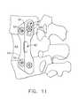
- FIG. 11is a lateral view of the plate system with the two posterior bolts installed
- FIG. 12is a lateral view of the plate system with C-rings for the anterior bolts
- FIG. 13is a lateral view of the plate system of the present invention completely installed
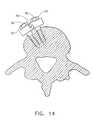
- FIG. 14is a sectional view of the system shown in FIG. 13;
- FIG. 15is a fragmentary view of an anterior hole of plate of the present invention showing the beveled orientation through the plate;
- FIG. 16is a lateral view of the plate system having slotted holes on the anterior section of the plate;
- FIG. 17is a lateral view of an alternative embodiment of the plate system of the present invention.
- FIG. 18is a side view of the plate shown in FIG. 17 partly in phantom;
- FIG. 19is a cross-sectional view of the plate shown in FIG. 17;
- FIG. 20is a plan view of a plate of the present invention which is angled for use on a kyphotic spine;
- FIG. 21is a plan view of a plate of the present invention which is angled for use on a lordotic spine.
- FIG. 22is a plan view of another embodiment of a spine plate according to the present invention.
- FIGS. 1-4depict one such prior art spinal stabilization system, comprising a spinal plate 10 placed across several vertebrae 12 , 14 .
- Plate 10contains a series of openings 16 which are intended to receive bone anchoring hardware.
- Two openings 16are positioned against vertebra 12
- two openings 16are positioned against vertebra 14 .
- a bone graft 18 positioned between vertebrae 12 , 14acts as a replacement for a damaged or otherwise removed vertebra.
- a pair of screws 20are installed through openings 16 on the anterior portion of plate 10
- a pair of bolts 22are installed through openings 16 on the posterior portion of plate 10
- Each bolt 22consists of a lower threaded section 23 and an upper threaded post 24 to which a nut 26 is affixed to secure bolt 22 in position.
- the threaded sections 21 , 23 of screws 20 and bolts 22are anchored in vertebrae 12 , 14 .
- bolts 22 and screws 20converge to resist pull-out, as shown in FIG. 4 .
- This screw and bolt combinationprovides increased spinal stability, as the bolts 22 rigidly affix the spinal plate 10 to the screws 20 , which are much easier to insert in the procedure.
- FIGS. 5-7show a preferred embodiment of a hinged spinal plate system 30 of the present invention, ideally suited for use in the lumbar/thoracic portion of the spine.
- Plate system 30includes a thin plate 32 having two plate elements 32 a , 32 b which are removably coupled together along a hinged section 34 .
- Element 32 acontains generally rounded edges 35 a , 35 b , a cutaway section 35 c , and two generally circular through openings 36 positioned collinearly along element 32 a .
- Element 32 bcontains generally rounded edges 38 a , 38 b , a cutaway section 38 c , and two generally circular through openings 40 positioned collinearly along element 32 b .
- openings 36 on plate element 32 aare shown as circular in this embodiment, and openings 40 on plate element 32 b are shown as elongated slots, openings 36 , 40 may be configured in any suitable combination of circular openings and elongated slots. Cutaway sections 35 c , 38 c afford the surgeon a better view of the bone graft inserted between vertebrae, in part to insure that the bone graft is not projecting into the spinal cord or nerves.
- Plate 32is preferably constructed from an implant grade titanium alloy, such as Ti-6Al-4V. Alternatively, plate 32 may be constructed from any number of suitable materials, such as stainless steel ASTM F138.
- Opening 42is formed along hinged section 34 of plate system 30 by a cutout section 42 a in element 32 a and a cutout section 42 b in element 32 b . Opening 42 may be used to accommodate additional hardware to increase the stability of plate system 30 against the spine. Also, opening 42 may be used if additional hardware is needed to secure the bone graft in position.
- Bolts 50are inserted through openings 36 , 40 to secure plate 32 to the vertebrae.
- Bolts 50contain a lower threaded portion 52 for threadedly engaging pre-drilled holes in the appropriate vertebrae of the spine, and an upper threaded portion 54 which extends through plate 32 after it has been installed in its proper position.
- Bolts 50contain an unthreaded middle portion located between lower threaded portion 52 and upper threaded portion 54 , as such bone-engaging screws are known to and used by those skilled in the art.
- a series of snap or C-rings 60are used with bolts 50 to securely fasten plate 32 in its proper position. Snap or C-rings 60 are clipped onto upper threaded portion 54 of bolts 50 after lower threaded portion 52 has been anchored within the appropriate vertebrae but before plate 32 has been fully installed. Alternatively, snap or C-rings 60 are clipped onto the middle unthreaded portion of bolt 50 in embodiments of plate system 30 utilizing such a bolt 50 . Finally, a series of nuts 62 are threaded onto upper threaded portion 54 of bolts 50 to secure plate 32 in its proper position. It is contemplated that alternative embodiments of plate system 30 may employ ordinary washers in place of snap or C-rings 60 .
- FIGS. 8-13The preferred method of using hinged plate system 30 is shown in FIGS. 8-13.
- a bone graft 63is inserted between vertebrae to serve as a replacement vertebra.
- two bolts 50are affixed within the appropriate vertebrae.
- a pair of holesare drilled into the vertebrae at a 15° anterior angulation using openings 40 as a guide.
- Bolts 50are then screwed into place through plate 32 to ensure placement in the proper location.
- upper bolt 50is placed into the cephalad portion of opening 40 as shown in FIG. 8 to allow for compression.
- the next stepinvolves flipping posterior element 32 b of plate 32 upwardly away from the vertebrae.
- posterior element 32 b and/or plate 32may be removed in its entirety.
- snap rings 60are applied to upper threaded portion 54 of bolts 50 to secure them in place.
- posterior element 32 b of plate 32is then repositioned over the two bolts 50 , by either flipping downward toward the vertebrae or by reconnecting posterior element 32 b to anterior element 32 a along hinged element 34 . While compressing bone graft 63 between the vertebrae, nut 62 is then applied to upper threaded portion 54 of lower bolt 50 , and securely tightened against plate 32 .
- the wrench used to tighten nut 62 onto lower bolt 50is cannulated to allow insertion of a screwdriver or other suitable tool to prevent rotation of bolt 50 while nut 62 is threaded onto upper threaded portion 54 of bolt 50 .
- a pair of holesare then drilled into the vertebrae using openings 36 on the anterior element 32 a as a guide.
- Bolts 50can then be affixed into place through element 32 a (FIG. 11 ).
- anterior element 32 ais then flipped upwardly or removed entirely, and snap rings 60 are secured on upper threaded portion 54 of bolts 50 .
- Element 32 a of plate 32can now be returned to its proper position, and nuts 62 are applied to upper threaded portion 54 of bolts 50 and tightened to completely secure plate 32 against the vertebrae, as shown in FIG. 13 .
- another screw 70may be inserted through opening 42 into bone graft 63 (or a cage if one has been inserted).
- FIG. 14is a sectional view of a vertebra on which hinged plate system 30 of the present invention has been installed.
- Bolts 50can be seen penetrating the vertebra.
- the relative angularity between bolts 50provides the force necessary to securely hold plate system 30 in the proper orientation to promote healing.
- hinged section 34assists to contour plate 32 to the convexity of the vertebrae, allowing plate 32 to more effectively contact the vertebral surface.
- openings 40 on element 32 bmay be beveled such that element 32 a can be lifted slightly while positioned on upper threaded portion 54 of bolt 50 , allowing snap ring 60 to be inserted below plate 32 onto bolt 50 without substantial displacement of element 32 a (FIG. 15 ).
- FIG. 16shows a plate 32 in which openings 40 in element 32 a are slotted toward rounded edges 35 a , 35 b such that element 32 a can be easily flipped in an upward direction.
- FIGS. 17-22An alternate embodiment of the spinal plate system of the present invention is shown in FIGS. 17-22.
- a spinal plate system 100is shown mounted in position on the spinal column of a patient.
- a unitary plate 102 having a plurality of slots 104 a-eis fastened by a plurality of bolts 110 at vertebrae 106 , 108 .
- a bone graft 112has been inserted between vertebrae 106 , 108 to serve as a replacement vertebra.
- Plate 102contains cutaway edge portions 113 a , 113 b to allow the surgeon to visualize the bone graft easily.
- Bolts 110which are shown mounted through slots 104 a-d , are held in place by a plurality of snap-rings 114 .
- Central slot 104 e located in the central region of plate 102may be used for an additional screw or bolt through a central vertebra or bone graft.
- the bottom surface of plate 102may contain a friction surface to allow better contact with
- FIG. 19shows a cross-sectional view of the plate of FIG. 17 .
- plate 102has a thickness of approximately 7 mm, and is curved to allow for better contact with the vertebral surface.
- Anterior slots 104 a , 104 bwhich each have a preferred width of approximately 7 mm, are substantially perpendicular to the upper and lower surfaces of plate 102 .
- Posterior slots 104 c , 104 dwhich each have a preferred width of approximately 7 mm , are oriented at approximately a 15° anterior angulation between the upper and lower surfaces of plate 102 .
- the preferred length of plate 102ranges from 60 mm to 100 mm.
- the preferred width of plate 102is approximately 20 mm at its widest portion, and approximately 12 mm across cutaway sections 112 a , 112 b.
- Plate 102can be shaped to more easily fit the spine when used in different areas.
- FIG. 20shows a plate 102 which is angled 15° in the forward (i.e. anterior) direction to compensate for kyphotic conditions
- FIG. 21shows a plate 102 which is angled 15° in the reverse (i.e. posterior) direction to compensate for lordotic conditions.
- FIG. 22depicts a shorter plate 102 , which may be used in situations where longer plates are impracticable or unnecessary.
Landscapes
- Health & Medical Sciences (AREA)
- Orthopedic Medicine & Surgery (AREA)
- Life Sciences & Earth Sciences (AREA)
- Neurology (AREA)
- Surgery (AREA)
- Heart & Thoracic Surgery (AREA)
- Engineering & Computer Science (AREA)
- Biomedical Technology (AREA)
- Nuclear Medicine, Radiotherapy & Molecular Imaging (AREA)
- Medical Informatics (AREA)
- Molecular Biology (AREA)
- Animal Behavior & Ethology (AREA)
- General Health & Medical Sciences (AREA)
- Public Health (AREA)
- Veterinary Medicine (AREA)
- Surgical Instruments (AREA)
- Prostheses (AREA)
- Dowels (AREA)
Abstract
Description
Claims (34)
Priority Applications (3)
| Application Number | Priority Date | Filing Date | Title |
|---|---|---|---|
| US10/108,287US6764489B2 (en) | 2001-03-27 | 2002-03-27 | Hinged anterior thoracic/lumbar plate |
| US10/860,850US7341590B2 (en) | 2001-03-27 | 2004-06-03 | Hinged anterior thoracic/lumbar plate |
| US12/046,425US20080228230A1 (en) | 2001-03-27 | 2008-03-11 | Hinged Bone Plate and Related Methods |
Applications Claiming Priority (2)
| Application Number | Priority Date | Filing Date | Title |
|---|---|---|---|
| US27915701P | 2001-03-27 | 2001-03-27 | |
| US10/108,287US6764489B2 (en) | 2001-03-27 | 2002-03-27 | Hinged anterior thoracic/lumbar plate |
Related Child Applications (1)
| Application Number | Title | Priority Date | Filing Date |
|---|---|---|---|
| US10/860,850DivisionUS7341590B2 (en) | 2001-03-27 | 2004-06-03 | Hinged anterior thoracic/lumbar plate |
Publications (2)
| Publication Number | Publication Date |
|---|---|
| US20020151896A1 US20020151896A1 (en) | 2002-10-17 |
| US6764489B2true US6764489B2 (en) | 2004-07-20 |
Family
ID=23067878
Family Applications (4)
| Application Number | Title | Priority Date | Filing Date |
|---|---|---|---|
| US10/108,015Expired - Fee RelatedUS6843790B2 (en) | 2001-03-27 | 2002-03-27 | Anatomic posterior lumbar plate |
| US10/108,287Expired - LifetimeUS6764489B2 (en) | 2001-03-27 | 2002-03-27 | Hinged anterior thoracic/lumbar plate |
| US10/860,850Expired - LifetimeUS7341590B2 (en) | 2001-03-27 | 2004-06-03 | Hinged anterior thoracic/lumbar plate |
| US12/046,425AbandonedUS20080228230A1 (en) | 2001-03-27 | 2008-03-11 | Hinged Bone Plate and Related Methods |
Family Applications Before (1)
| Application Number | Title | Priority Date | Filing Date |
|---|---|---|---|
| US10/108,015Expired - Fee RelatedUS6843790B2 (en) | 2001-03-27 | 2002-03-27 | Anatomic posterior lumbar plate |
Family Applications After (2)
| Application Number | Title | Priority Date | Filing Date |
|---|---|---|---|
| US10/860,850Expired - LifetimeUS7341590B2 (en) | 2001-03-27 | 2004-06-03 | Hinged anterior thoracic/lumbar plate |
| US12/046,425AbandonedUS20080228230A1 (en) | 2001-03-27 | 2008-03-11 | Hinged Bone Plate and Related Methods |
Country Status (3)
| Country | Link |
|---|---|
| US (4) | US6843790B2 (en) |
| AU (1) | AU2002336069A1 (en) |
| WO (2) | WO2002076317A1 (en) |
Cited By (61)
| Publication number | Priority date | Publication date | Assignee | Title |
|---|---|---|---|---|
| US20040111089A1 (en)* | 2002-12-04 | 2004-06-10 | Stevens Peter M. | Bone alignment implant and method of use |
| US20040127900A1 (en)* | 2002-12-31 | 2004-07-01 | Konieczynski David D. | Resilient bone plate and screw system allowing bi-directional assembly |
| US20040127899A1 (en)* | 2002-12-31 | 2004-07-01 | Konieczynski David D. | Bone plate and screw system allowing bi-directional attachment |
| US20040153069A1 (en)* | 2001-12-14 | 2004-08-05 | Paul Kamaljit S. | Spinal plate assembly |
| US20040153078A1 (en)* | 2003-01-30 | 2004-08-05 | Grinberg Alexander D | Anterior buttress staple |
| US20040181229A1 (en)* | 2001-06-04 | 2004-09-16 | Michelson Gary K. | Instrumentation for use with dynamic single-lock anterior cervical plate system having non-detachably fastened and moveable segments |
| US20050027298A1 (en)* | 2001-06-06 | 2005-02-03 | Michelson Gary K. | Dynamic, modular, multilock anterior cervical plate system having detachably fastened assembleable and moveable segments and instrumentation for installation thereof |
| US20050027297A1 (en)* | 2001-06-04 | 2005-02-03 | Michelson Gary K. | Dynamic, modular, single-lock anterior cervical plate system having assembleable and moveable segments and instrumentation for installation thereof |
| US20050070908A1 (en)* | 2000-02-16 | 2005-03-31 | Cragg Andrew H. | Articulating spinal implant |
| US20050085816A1 (en)* | 2001-06-04 | 2005-04-21 | Michelson Gary K. | Method for installation of dynamic anterior cervical plate system having moveable segments |
| US20050113919A1 (en)* | 2000-02-16 | 2005-05-26 | Cragg Andrew H. | Prosthetic nucleus apparatus |
| US20050137607A1 (en)* | 2003-10-23 | 2005-06-23 | Assell Robert L. | Bone dilator system |
| US20050187554A1 (en)* | 2001-06-04 | 2005-08-25 | Michelson Gary K. | Method for installation of anterior cervical plate system having vertebral body engaging anchors and connecting plate |
| US20050192576A1 (en)* | 2001-06-06 | 2005-09-01 | Michelson Gary K. | Method for installing dynamic multilock anterior cervical plate system having detachably fastened and moveable segments |
| US20050288668A1 (en)* | 2002-06-24 | 2005-12-29 | Bernhard Brinkhaus | Spinal column support system |
| US20050288673A1 (en)* | 2003-12-19 | 2005-12-29 | Adrian Catbagan | Low profile anterior thoracic and thoracolumbar plate |
| US20060058800A1 (en)* | 2002-12-03 | 2006-03-16 | Trans1 Inc. | Methods and apparatus for provision of therapy to adjacent motion segments |
| US20060079898A1 (en)* | 2003-10-23 | 2006-04-13 | Trans1 Inc. | Spinal motion preservation assemblies |
| US20060155285A1 (en)* | 2005-01-12 | 2006-07-13 | Kent Anderson | Anchor retaining mechanisms for bone plates |
| US20060155297A1 (en)* | 2003-10-23 | 2006-07-13 | Ainsworth Stephen D | Driver assembly for simultaneous axial delivery of spinal implants |
| US20060247639A1 (en)* | 2005-04-29 | 2006-11-02 | Sdgi Holdings, Inc. | Apparatus for retaining a bone anchor in a bone plate and method for use thereof |
| US20060271052A1 (en)* | 2005-05-12 | 2006-11-30 | Stern Joseph D | Revisable anterior cervical plating system |
| US20060276897A1 (en)* | 2004-12-13 | 2006-12-07 | St. Francis Medical Technologies, Inc. | Implant for stabilizing a bone graft during spinal fusion |
| US20070010717A1 (en)* | 2000-02-16 | 2007-01-11 | Cragg Andrew H | Methods of performing procedures in the spine |
| US20070168036A1 (en)* | 2003-10-23 | 2007-07-19 | Trans1 Inc. | Spinal motion preservation assemblies |
| US20070233107A1 (en)* | 2006-02-27 | 2007-10-04 | Zielinski Steven C | Method and apparatus for lateral reduction and fusion of the spine |
| US7309338B2 (en) | 2000-02-16 | 2007-12-18 | Trans1 Inc. | Methods and apparatus for performing therapeutic procedures in the spine |
| US20070293865A1 (en)* | 2006-06-09 | 2007-12-20 | Gyrus Productions | Method of performing a decompressive craniectomy |
| US20080004707A1 (en)* | 2003-10-23 | 2008-01-03 | Cragg Andrew H | Prosthetic nucleus apparatus and method |
| US20080027439A1 (en)* | 2006-07-31 | 2008-01-31 | Sasing Jude L | Cervical plate system having an insertable rotating element |
| US20080091206A1 (en)* | 2006-10-13 | 2008-04-17 | Jeffrey Johnson | Bone Plate |
| US20080097448A1 (en)* | 2006-10-18 | 2008-04-24 | Lawrence Binder | Rotatable Bone Plate |
| US20080262502A1 (en)* | 2006-10-24 | 2008-10-23 | Trans1, Inc. | Multi-membrane prosthetic nucleus |
| US20080312699A1 (en)* | 2007-04-11 | 2008-12-18 | Jeffrey Johnson | Recessed plate system |
| US20090012569A1 (en)* | 2005-03-17 | 2009-01-08 | Desmond Meiring Dall | Configurable Bone Fixation System |
| USD592946S1 (en) | 2007-07-25 | 2009-05-26 | Spinal U.S.A. | Locking rivet head |
| US20090192618A1 (en)* | 2008-01-30 | 2009-07-30 | Zielinski Steven C | Artificial spinal disk |
| US7608077B2 (en) | 2000-02-16 | 2009-10-27 | Trans1 Inc. | Method and apparatus for spinal distraction and fusion |
| US20090270925A1 (en)* | 2008-04-23 | 2009-10-29 | Aryan Henry E | Bone plate system and method |
| US20090326580A1 (en)* | 2008-06-25 | 2009-12-31 | Anderson Mark E | Spinal fixation device |
| US20100016900A1 (en)* | 2008-07-21 | 2010-01-21 | Osteomed L.P. | System and Method for Fracture Reduction |
| US7727263B2 (en) | 2000-02-16 | 2010-06-01 | Trans1, Inc. | Articulating spinal implant |
| US20100145462A1 (en)* | 2006-10-24 | 2010-06-10 | Trans1 Inc. | Preformed membranes for use in intervertebral disc spaces |
| US20110040329A1 (en)* | 2009-08-14 | 2011-02-17 | Ainsworth Stephen D | Spinal therapy device with fixated distraction distance |
| US8070749B2 (en) | 2005-05-12 | 2011-12-06 | Stern Joseph D | Revisable anterior cervical plating system |
| US9078713B2 (en) | 2008-10-02 | 2015-07-14 | Memometal Technologies | Orthopedic implant in the form of a plate to be fixed between two bone parts |
| US9433404B2 (en) | 2012-10-31 | 2016-09-06 | Suture Concepts Inc. | Method and apparatus for closing fissures in the annulus fibrosus |
| US9814598B2 (en) | 2013-03-14 | 2017-11-14 | Quandary Medical, Llc | Spinal implants and implantation system |
| US9949734B2 (en) | 2012-10-31 | 2018-04-24 | Suture Concepts Inc. | Method and apparatus for closing a fissure in the annulus of an intervertebral disc, and/or for effecting other anatomical repairs and/or fixations |
| US10321833B2 (en) | 2016-10-05 | 2019-06-18 | Innovative Surgical Solutions. | Neural locating method |
| US10376208B2 (en) | 2013-09-20 | 2019-08-13 | Innovative Surgical Solutions, Llc | Nerve mapping system |
| US10376209B2 (en) | 2013-09-20 | 2019-08-13 | Innovative Surgical Solutions, Llc | Neural locating method |
| US10449002B2 (en) | 2013-09-20 | 2019-10-22 | Innovative Surgical Solutions, Llc | Method of mapping a nerve |
| US10478097B2 (en) | 2013-08-13 | 2019-11-19 | Innovative Surgical Solutions | Neural event detection |
| US10478096B2 (en) | 2013-08-13 | 2019-11-19 | Innovative Surgical Solutions. | Neural event detection |
| US10786235B2 (en) | 2012-10-31 | 2020-09-29 | Anchor Innovation Medical, Inc. | Method and apparatus for closing a fissure in the annulus of an intervertebral disc, and/or for effecting other anatomical repairs and/or fixations |
| US10870002B2 (en) | 2018-10-12 | 2020-12-22 | DePuy Synthes Products, Inc. | Neuromuscular sensing device with multi-sensor array |
| US10869616B2 (en) | 2018-06-01 | 2020-12-22 | DePuy Synthes Products, Inc. | Neural event detection |
| US11123117B1 (en)* | 2011-11-01 | 2021-09-21 | Nuvasive, Inc. | Surgical fixation system and related methods |
| US11399777B2 (en) | 2019-09-27 | 2022-08-02 | DePuy Synthes Products, Inc. | Intraoperative neural monitoring system and method |
| US11452554B2 (en)* | 2014-07-16 | 2022-09-27 | The Regents Of The University Of Colorado | System and method for fastening of two or more interacting elements |
Families Citing this family (162)
| Publication number | Priority date | Publication date | Assignee | Title |
|---|---|---|---|---|
| US7766947B2 (en) | 2001-10-31 | 2010-08-03 | Ortho Development Corporation | Cervical plate for stabilizing the human spine |
| US6755833B1 (en) | 2001-12-14 | 2004-06-29 | Kamaljit S. Paul | Bone support assembly |
| US7615070B2 (en)* | 2002-10-11 | 2009-11-10 | Spineco, Inc. | Electro-stimulation and medical delivery device |
| TWI315010B (en)* | 2003-03-31 | 2009-09-21 | Sharp Corporatio | Liquid crystal display device and method of manufacturing the same |
| US20050049595A1 (en) | 2003-09-03 | 2005-03-03 | Suh Sean S. | Track-plate carriage system |
| US7909860B2 (en) | 2003-09-03 | 2011-03-22 | Synthes Usa, Llc | Bone plate with captive clips |
| US8070785B2 (en)* | 2003-09-16 | 2011-12-06 | Spineco, Inc. | Bone anchor prosthesis and system |
| US7955355B2 (en) | 2003-09-24 | 2011-06-07 | Stryker Spine | Methods and devices for improving percutaneous access in minimally invasive surgeries |
| US7967826B2 (en) | 2003-10-21 | 2011-06-28 | Theken Spine, Llc | Connector transfer tool for internal structure stabilization systems |
| US7588575B2 (en)* | 2003-10-21 | 2009-09-15 | Innovative Spinal Technologies | Extension for use with stabilization systems for internal structures |
| US7588590B2 (en) | 2003-12-10 | 2009-09-15 | Facet Solutions, Inc | Spinal facet implant with spherical implant apposition surface and bone bed and methods of use |
| FR2865376B1 (en)* | 2004-01-27 | 2006-03-17 | Medicrea | MATERIAL OF VERTEBRAL OSTEOSYNTHESIS |
| US8333789B2 (en) | 2007-01-10 | 2012-12-18 | Gmedelaware 2 Llc | Facet joint replacement |
| US8562649B2 (en) | 2004-02-17 | 2013-10-22 | Gmedelaware 2 Llc | System and method for multiple level facet joint arthroplasty and fusion |
| US7993373B2 (en)* | 2005-02-22 | 2011-08-09 | Hoy Robert W | Polyaxial orthopedic fastening apparatus |
| US8900277B2 (en) | 2004-02-26 | 2014-12-02 | Pioneer Surgical Technology, Inc. | Bone plate system |
| US7740649B2 (en) | 2004-02-26 | 2010-06-22 | Pioneer Surgical Technology, Inc. | Bone plate system and methods |
| US7648520B2 (en)* | 2004-04-16 | 2010-01-19 | Kyphon Sarl | Pedicle screw assembly |
| US7524323B2 (en)* | 2004-04-16 | 2009-04-28 | Kyphon Sarl | Subcutaneous support |
| US7789899B2 (en) | 2004-12-30 | 2010-09-07 | Warsaw Orthopedic, Inc. | Bone anchorage screw with built-in hinged plate |
| US7618418B2 (en)* | 2004-04-16 | 2009-11-17 | Kyphon Sarl | Plate system for minimally invasive support of the spine |
| US7811311B2 (en)* | 2004-12-30 | 2010-10-12 | Warsaw Orthopedic, Inc. | Screw with deployable interlaced dual rods |
| US7507242B2 (en) | 2004-06-02 | 2009-03-24 | Facet Solutions | Surgical measurement and resection framework |
| CA2580101A1 (en)* | 2004-09-14 | 2006-03-23 | Spineco, Inc. | Implant device |
| WO2006034436A2 (en) | 2004-09-21 | 2006-03-30 | Stout Medical Group, L.P. | Expandable support device and method of use |
| US9615866B1 (en) | 2004-10-18 | 2017-04-11 | Nuvasive, Inc. | Surgical fixation system and related methods |
| AU2005302633A1 (en)* | 2004-10-28 | 2006-05-11 | Axial Biotech, Inc. | Apparatus and method for concave scoliosis expansion |
| US7569061B2 (en) | 2004-11-16 | 2009-08-04 | Innovative Spinal Technologies, Inc. | Off-axis anchor guidance system |
| US20060195089A1 (en)* | 2005-02-03 | 2006-08-31 | Lehuec Jean-Charles | Spinal plating and intervertebral support systems and methods |
| US7500976B2 (en)* | 2005-03-11 | 2009-03-10 | Synthes Usa, Llc | Translational scissor plate fixation system |
| US7678113B2 (en)* | 2005-04-19 | 2010-03-16 | Warsaw Orthopedic, Inc. | Antero-lateral plating systems and methods for spinal stabilization |
| US20060242813A1 (en)* | 2005-04-29 | 2006-11-02 | Fred Molz | Metal injection molding of spinal fixation systems components |
| US8177817B2 (en) | 2005-05-18 | 2012-05-15 | Stryker Spine | System and method for orthopedic implant configuration |
| EP1903949A2 (en) | 2005-07-14 | 2008-04-02 | Stout Medical Group, L.P. | Expandable support device and method of use |
| EP1981422B1 (en)* | 2006-02-06 | 2018-10-24 | Stryker European Holdings I, LLC | Rod contouring apparatus for percutaneous pedicle screw extension |
| US20070233108A1 (en)* | 2006-03-15 | 2007-10-04 | Stalcup Gregory C | Spine fixation device |
| EP2023864B1 (en) | 2006-05-01 | 2019-07-10 | Stout Medical Group, L.P. | Expandable support device |
| US20070276438A1 (en)* | 2006-05-26 | 2007-11-29 | Michelle Meglin | Back alignment device |
| GB0617709D0 (en)* | 2006-09-08 | 2006-10-18 | Depuy Int Ltd | A bone plate for fixation to a patient's vertebrae |
| US8262710B2 (en)* | 2006-10-24 | 2012-09-11 | Aesculap Implant Systems, Llc | Dynamic stabilization device for anterior lower lumbar vertebral fusion |
| WO2008073907A2 (en)* | 2006-12-08 | 2008-06-19 | Alpinespine Llc | Compliant cervical screw locking mechanism |
| US9039768B2 (en) | 2006-12-22 | 2015-05-26 | Medos International Sarl | Composite vertebral spacers and instrument |
| US8034081B2 (en) | 2007-02-06 | 2011-10-11 | CollabComl, LLC | Interspinous dynamic stabilization implant and method of implanting |
| US8449581B2 (en)* | 2007-05-07 | 2013-05-28 | Stryker Trauma Gmbh | Sliding plate with reinforced slot |
| US8623019B2 (en) | 2007-07-03 | 2014-01-07 | Pioneer Surgical Technology, Inc. | Bone plate system |
| US8361126B2 (en) | 2007-07-03 | 2013-01-29 | Pioneer Surgical Technology, Inc. | Bone plate system |
| US10758283B2 (en) | 2016-08-11 | 2020-09-01 | Mighty Oak Medical, Inc. | Fixation devices having fenestrations and methods for using the same |
| US20090043341A1 (en)* | 2007-08-09 | 2009-02-12 | Aesculap, Inc. | Dynamic extension plate for anterior cervical fusion and method of installation |
| WO2009055537A1 (en) | 2007-10-23 | 2009-04-30 | K2M, Inc. | Dynamic cervical plate |
| DE102007058108A1 (en)* | 2007-12-03 | 2009-06-04 | Mondeal Medical Systems Gmbh | Anchoring device for tooth and / or jaw regulation |
| CA2702585A1 (en)* | 2007-12-19 | 2009-06-25 | Oregon Health & Science University | Method and apparatus for dens fracture fixation |
| US8007522B2 (en) | 2008-02-04 | 2011-08-30 | Depuy Spine, Inc. | Methods for correction of spinal deformities |
| US8088163B1 (en) | 2008-02-06 | 2012-01-03 | Kleiner Jeffrey B | Tools and methods for spinal fusion |
| US20090248092A1 (en) | 2008-03-26 | 2009-10-01 | Jonathan Bellas | Posterior Intervertebral Disc Inserter and Expansion Techniques |
| US20210378834A1 (en) | 2008-05-22 | 2021-12-09 | Spinal Surgical Strategies, Inc., A Nevada Corporation D/B/A Kleiner Device Labs | Spinal fusion cage system with inserter |
| USD853560S1 (en) | 2008-10-09 | 2019-07-09 | Nuvasive, Inc. | Spinal implant insertion device |
| US20100114171A1 (en)* | 2008-11-05 | 2010-05-06 | K2M, Inc. | Multi-planar spinal fixation assembly with locking element |
| WO2010056895A1 (en) | 2008-11-12 | 2010-05-20 | Stout Medical Group, L.P. | Fixation device and method |
| US20100211176A1 (en) | 2008-11-12 | 2010-08-19 | Stout Medical Group, L.P. | Fixation device and method |
| US8366748B2 (en) | 2008-12-05 | 2013-02-05 | Kleiner Jeffrey | Apparatus and method of spinal implant and fusion |
| US8864654B2 (en) | 2010-04-20 | 2014-10-21 | Jeffrey B. Kleiner | Method and apparatus for performing retro peritoneal dissection |
| US9717403B2 (en) | 2008-12-05 | 2017-08-01 | Jeffrey B. Kleiner | Method and apparatus for performing retro peritoneal dissection |
| AU2009329873A1 (en) | 2008-12-26 | 2011-11-03 | Scott Spann | Minimally-invasive retroperitoneal lateral approach for spinal surgery |
| USD656610S1 (en) | 2009-02-06 | 2012-03-27 | Kleiner Jeffrey B | Spinal distraction instrument |
| US9247943B1 (en) | 2009-02-06 | 2016-02-02 | Kleiner Intellectual Property, Llc | Devices and methods for preparing an intervertebral workspace |
| US9526620B2 (en) | 2009-03-30 | 2016-12-27 | DePuy Synthes Products, Inc. | Zero profile spinal fusion cage |
| CN102413779B (en) | 2009-05-05 | 2014-03-12 | 斯恩蒂斯有限公司 | nail locking system |
| US10349980B2 (en) | 2009-08-27 | 2019-07-16 | The Foundry, Llc | Method and apparatus for altering biomechanics of the shoulder |
| US9278004B2 (en) | 2009-08-27 | 2016-03-08 | Cotera, Inc. | Method and apparatus for altering biomechanics of the articular joints |
| US9668868B2 (en) | 2009-08-27 | 2017-06-06 | Cotera, Inc. | Apparatus and methods for treatment of patellofemoral conditions |
| CA2771332C (en) | 2009-08-27 | 2020-11-10 | Cotera, Inc. | Method and apparatus for force redistribution in articular joints |
| US9861408B2 (en) | 2009-08-27 | 2018-01-09 | The Foundry, Llc | Method and apparatus for treating canine cruciate ligament disease |
| USD723682S1 (en) | 2013-05-03 | 2015-03-03 | Spinal Surgical Strategies, Llc | Bone graft delivery tool |
| US8685031B2 (en) | 2009-09-18 | 2014-04-01 | Spinal Surgical Strategies, Llc | Bone graft delivery system |
| US9186193B2 (en) | 2009-09-18 | 2015-11-17 | Spinal Surgical Strategies, Llc | Fusion cage with combined biological delivery system |
| US10973656B2 (en) | 2009-09-18 | 2021-04-13 | Spinal Surgical Strategies, Inc. | Bone graft delivery system and method for using same |
| US20170238984A1 (en) | 2009-09-18 | 2017-08-24 | Spinal Surgical Strategies, Llc | Bone graft delivery device with positioning handle |
| US10245159B1 (en) | 2009-09-18 | 2019-04-02 | Spinal Surgical Strategies, Llc | Bone graft delivery system and method for using same |
| US9060877B2 (en) | 2009-09-18 | 2015-06-23 | Spinal Surgical Strategies, Llc | Fusion cage with combined biological delivery system |
| US9629729B2 (en) | 2009-09-18 | 2017-04-25 | Spinal Surgical Strategies, Llc | Biological delivery system with adaptable fusion cage interface |
| USD750249S1 (en) | 2014-10-20 | 2016-02-23 | Spinal Surgical Strategies, Llc | Expandable fusion cage |
| US8906028B2 (en) | 2009-09-18 | 2014-12-09 | Spinal Surgical Strategies, Llc | Bone graft delivery device and method of using the same |
| US9173694B2 (en) | 2009-09-18 | 2015-11-03 | Spinal Surgical Strategies, Llc | Fusion cage with combined biological delivery system |
| US9011494B2 (en)* | 2009-09-24 | 2015-04-21 | Warsaw Orthopedic, Inc. | Composite vertebral rod system and methods of use |
| US9393129B2 (en) | 2009-12-10 | 2016-07-19 | DePuy Synthes Products, Inc. | Bellows-like expandable interbody fusion cage |
| US20110218574A1 (en)* | 2010-03-03 | 2011-09-08 | Warsaw Orthopedic, Inc. | Dynamic vertebral construct |
| US8535380B2 (en) | 2010-05-13 | 2013-09-17 | Stout Medical Group, L.P. | Fixation device and method |
| US11813034B2 (en) | 2010-06-07 | 2023-11-14 | Creative Surgical Solutions, Llc | Surgical drape with separable elements |
| US8726907B2 (en) | 2010-06-07 | 2014-05-20 | Eric Strauch | Surgical drape with separable elements |
| US10363108B2 (en) | 2010-06-07 | 2019-07-30 | Creative Surgical Solutions, Llc | Surgical drape with separable elements |
| US11806197B2 (en) | 2010-06-29 | 2023-11-07 | Mighty Oak Medical, Inc. | Patient-matched apparatus for use in spine related surgical procedures and methods for using the same |
| US11039889B2 (en) | 2010-06-29 | 2021-06-22 | Mighty Oak Medical, Inc. | Patient-matched apparatus and methods for performing surgical procedures |
| US12357413B2 (en) | 2010-06-29 | 2025-07-15 | Mighty Oak Medical, Inc. | Patient-matched apparatus for use in spine related surgical procedures and methods for using the same |
| US11376073B2 (en) | 2010-06-29 | 2022-07-05 | Mighty Oak Medical Inc. | Patient-matched apparatus and methods for performing surgical procedures |
| WO2017066518A1 (en) | 2010-06-29 | 2017-04-20 | Mighty Oak Medical, Inc. | Patient-matched apparatus and methods for performing surgical procedures |
| EP2608747A4 (en) | 2010-08-24 | 2015-02-11 | Flexmedex Llc | Support device and method for use |
| US9179946B2 (en) | 2010-09-13 | 2015-11-10 | Daniel Nehls | Low-profile anterior vertebral plate assemblies and methods of use |
| AU2011305680B2 (en) | 2010-09-20 | 2014-09-11 | Jeffrey Kleiner | Fusion cage with combined biological delivery system |
| US20120078372A1 (en) | 2010-09-23 | 2012-03-29 | Thomas Gamache | Novel implant inserter having a laterally-extending dovetail engagement feature |
| US11529241B2 (en) | 2010-09-23 | 2022-12-20 | DePuy Synthes Products, Inc. | Fusion cage with in-line single piece fixation |
| US20120078373A1 (en) | 2010-09-23 | 2012-03-29 | Thomas Gamache | Stand alone intervertebral fusion device |
| US10342583B2 (en) | 2010-10-01 | 2019-07-09 | K2M, Inc. | Dynamic plate with inserts |
| US9149286B1 (en) | 2010-11-12 | 2015-10-06 | Flexmedex, LLC | Guidance tool and method for use |
| US10136932B2 (en) | 2010-12-20 | 2018-11-27 | Camber Spine Technologies, LLC | Spinal plate and distraction/compression pin system |
| US20120158066A1 (en)* | 2010-12-20 | 2012-06-21 | Camber Spine Technologies, LLC | Adjustable cervical plate |
| US9358122B2 (en) | 2011-01-07 | 2016-06-07 | K2M, Inc. | Interbody spacer |
| RU2605147C2 (en) | 2011-04-01 | 2016-12-20 | Зинтес Гмбх | System for posterior spinal fixation with plate |
| US8668723B2 (en) | 2011-07-19 | 2014-03-11 | Neurostructures, Inc. | Anterior cervical plate |
| EP2747682A4 (en) | 2011-08-23 | 2015-01-21 | Flexmedex Llc | Tissue removal device and method |
| US9248028B2 (en) | 2011-09-16 | 2016-02-02 | DePuy Synthes Products, Inc. | Removable, bone-securing cover plate for intervertebral fusion cage |
| US20130158610A1 (en)* | 2011-12-16 | 2013-06-20 | Depuy Mitek, Inc. | Bone graft fixation systems and methods |
| US8852278B2 (en) | 2011-12-22 | 2014-10-07 | DePuy Synthes Products, LLC | Lateral cage with integrated plate |
| US9271836B2 (en) | 2012-03-06 | 2016-03-01 | DePuy Synthes Products, Inc. | Nubbed plate |
| US9913666B2 (en) | 2012-04-04 | 2018-03-13 | Carl P. Giordano | Plates configured to rigidly fix fragments of a pars interarticularis to one another |
| US9615860B2 (en)* | 2012-04-04 | 2017-04-11 | Carl Pasquale Giordano | Plates configured to rigidly fix fragments of a pars interarticularis to one another |
| US20130345813A1 (en)* | 2012-06-22 | 2013-12-26 | Sheryl Frank | Dual Anchor Lateral Vertebral Body Fixation Plates |
| AU2013282268A1 (en) | 2012-06-29 | 2015-01-22 | DePuy Synthes Products, LLC | Lateral insertion spinal implant |
| US9468466B1 (en) | 2012-08-24 | 2016-10-18 | Cotera, Inc. | Method and apparatus for altering biomechanics of the spine |
| US9782204B2 (en) | 2012-09-28 | 2017-10-10 | Medos International Sarl | Bone anchor assemblies |
| US20160166296A9 (en)* | 2012-10-22 | 2016-06-16 | Globus Medical, Inc. | Posterior Lumbar Plate |
| US10182921B2 (en) | 2012-11-09 | 2019-01-22 | DePuy Synthes Products, Inc. | Interbody device with opening to allow packing graft and other biologics |
| US9827020B2 (en) | 2013-03-14 | 2017-11-28 | Stryker European Holdings I, Llc | Percutaneous spinal cross link system and method |
| US9259247B2 (en) | 2013-03-14 | 2016-02-16 | Medos International Sarl | Locking compression members for use with bone anchor assemblies and methods |
| CA2846149C (en) | 2013-03-14 | 2018-03-20 | Stryker Spine | Systems and methods for percutaneous spinal fusion |
| US20140277153A1 (en) | 2013-03-14 | 2014-09-18 | DePuy Synthes Products, LLC | Bone Anchor Assemblies and Methods With Improved Locking |
| US9775660B2 (en) | 2013-03-14 | 2017-10-03 | DePuy Synthes Products, Inc. | Bottom-loading bone anchor assemblies and methods |
| US9724145B2 (en) | 2013-03-14 | 2017-08-08 | Medos International Sarl | Bone anchor assemblies with multiple component bottom loading bone anchors |
| US10342582B2 (en) | 2013-03-14 | 2019-07-09 | DePuy Synthes Products, Inc. | Bone anchor assemblies and methods with improved locking |
| DE102013104887B4 (en)* | 2013-05-13 | 2021-03-18 | Aap Implantate Ag | Osteosynthesis plate and segment for an osteosynthesis plate |
| JP6259513B2 (en) | 2013-06-07 | 2018-01-10 | フライ, ジョージFREY, George | Patient-compatible instruments and methods for performing surgical procedures |
| US9579128B2 (en) | 2013-07-19 | 2017-02-28 | K2M, Inc. | Translational plate and compressor instrument |
| US9468479B2 (en) | 2013-09-06 | 2016-10-18 | Cardinal Health 247, Inc. | Bone plate |
| US9629664B2 (en) | 2014-01-20 | 2017-04-25 | Neurostructures, Inc. | Anterior cervical plate |
| US9486250B2 (en) | 2014-02-20 | 2016-11-08 | Mastros Innovations, LLC. | Lateral plate |
| CA3008161C (en) | 2014-12-09 | 2023-09-26 | John A. Heflin | Spine alignment system |
| USD804584S1 (en)* | 2015-08-20 | 2017-12-05 | Troy Miles | Chiropractic adjusting toy for kids |
| USD797290S1 (en) | 2015-10-19 | 2017-09-12 | Spinal Surgical Strategies, Llc | Bone graft delivery tool |
| DE102017101882A1 (en) | 2016-02-02 | 2017-08-03 | Özlem Catikkaya | Work equipment for the stabilization of bone fractures |
| US12016573B2 (en) | 2016-08-11 | 2024-06-25 | Mighty Oak Medical, Inc. | Drill apparatus and surgical fixation devices and methods for using the same |
| US10743890B2 (en) | 2016-08-11 | 2020-08-18 | Mighty Oak Medical, Inc. | Drill apparatus and surgical fixation devices and methods for using the same |
| EP3357459A1 (en) | 2017-02-03 | 2018-08-08 | Spinal Surgical Strategies, LLC | Bone graft delivery device with positioning handle |
| US10828071B2 (en)* | 2017-02-21 | 2020-11-10 | Avery M. Jackson | Hinged anterior cervical locking plate system |
| US10716553B2 (en) | 2017-04-19 | 2020-07-21 | Pantheon Spinal, Llc | Spine surgery retractor system and related methods |
| US10512547B2 (en) | 2017-05-04 | 2019-12-24 | Neurostructures, Inc. | Interbody spacer |
| US10980641B2 (en) | 2017-05-04 | 2021-04-20 | Neurostructures, Inc. | Interbody spacer |
| US10940016B2 (en) | 2017-07-05 | 2021-03-09 | Medos International Sarl | Expandable intervertebral fusion cage |
| AU2018222968A1 (en) | 2017-08-31 | 2019-03-14 | Tidi Products, Llc | Separable sterile drape with z-shaped folds |
| USD857893S1 (en) | 2017-10-26 | 2019-08-27 | Mighty Oak Medical, Inc. | Cortical surgical guide |
| USD858765S1 (en) | 2017-10-26 | 2019-09-03 | Mighty Oak Medical, Inc. | Cortical surgical guide |
| USD948717S1 (en) | 2018-06-04 | 2022-04-12 | Mighty Oak Medical, Inc. | Sacro-iliac guide |
| USD895111S1 (en) | 2018-06-04 | 2020-09-01 | Mighty Oak Medical, Inc. | Sacro-iliac guide |
| US11076892B2 (en) | 2018-08-03 | 2021-08-03 | Neurostructures, Inc. | Anterior cervical plate |
| US11071629B2 (en) | 2018-10-13 | 2021-07-27 | Neurostructures Inc. | Interbody spacer |
| JP7487222B2 (en) | 2019-03-26 | 2024-05-20 | マイティ オーク メディカル、インコーポレイテッド | Patient-adapted device for use in augmented reality assisted surgery and method for using same - Patents.com |
| US11389209B2 (en) | 2019-07-19 | 2022-07-19 | Medos International Sarl | Surgical plating systems, devices, and related methods |
| WO2021092565A1 (en)* | 2019-11-07 | 2021-05-14 | Freedom Innovations, Llc | Implantable modular orthopedic plate system |
| US11877779B2 (en) | 2020-03-26 | 2024-01-23 | Xtant Medical Holdings, Inc. | Bone plate system |
| US11382761B2 (en) | 2020-04-11 | 2022-07-12 | Neurostructures, Inc. | Expandable interbody spacer |
| US11304817B2 (en) | 2020-06-05 | 2022-04-19 | Neurostructures, Inc. | Expandable interbody spacer |
| AU2021351559A1 (en) | 2020-10-04 | 2023-06-15 | Creative Surgical Solutions, Llc | Surgical drape with separable elements |
| US11717419B2 (en) | 2020-12-10 | 2023-08-08 | Neurostructures, Inc. | Expandable interbody spacer |
| WO2022184797A1 (en) | 2021-03-05 | 2022-09-09 | Medos International Sarl | Selectively locking polyaxial screw |
Citations (13)
| Publication number | Priority date | Publication date | Assignee | Title |
|---|---|---|---|---|
| US4448191A (en) | 1981-07-07 | 1984-05-15 | Rodnyansky Lazar I | Implantable correctant of a spinal curvature and a method for treatment of a spinal curvature |
| US5242443A (en) | 1991-08-15 | 1993-09-07 | Smith & Nephew Dyonics, Inc. | Percutaneous fixation of vertebrae |
| WO1997022306A1 (en) | 1995-12-20 | 1997-06-26 | Smith & Nephew Inc. | Osteosynthesis apparatus |
| US5772661A (en) | 1988-06-13 | 1998-06-30 | Michelson; Gary Karlin | Methods and instrumentation for the surgical correction of human thoracic and lumbar spinal disease from the antero-lateral aspect of the spine |
| US5840440A (en) | 1995-11-20 | 1998-11-24 | Ovonic Battery Company, Inc. | Hydrogen storage materials having a high density of non-conventional useable hydrogen storing sites |
| US5954722A (en) | 1997-07-29 | 1999-09-21 | Depuy Acromed, Inc. | Polyaxial locking plate |
| DE9219204U1 (en) | 1992-01-17 | 1999-12-16 | Ulrich, Heinrich, 89075 Ulm | Peg plate |
| US6030389A (en) | 1997-08-04 | 2000-02-29 | Spinal Concepts, Inc. | System and method for stabilizing the human spine with a bone plate |
| US6280445B1 (en)* | 1999-04-16 | 2001-08-28 | Sdgi Holdings, Inc. | Multi-axial bone anchor system |
| US6432106B1 (en) | 1999-11-24 | 2002-08-13 | Depuy Acromed, Inc. | Anterior lumbar interbody fusion cage with locking plate |
| US6458131B1 (en) | 2000-08-07 | 2002-10-01 | Salut, Ltd. | Apparatus and method for reducing spinal deformity |
| US20020143336A1 (en)* | 2001-02-23 | 2002-10-03 | Hearn James P. | Sternum fixation device |
| US6565571B1 (en) | 1998-10-19 | 2003-05-20 | Scient'x | Anterior osteosynthesis plate for lumbar vertebrae or sacral lumbar vertebra and instrument for positioning same |
Family Cites Families (39)
| Publication number | Priority date | Publication date | Assignee | Title |
|---|---|---|---|---|
| US731138A (en)* | 1903-02-24 | 1903-06-16 | William B Stearns | Skylight for vessels. |
| US2199102A (en)* | 1938-08-10 | 1940-04-30 | Weber Knapp Co | Hinge |
| US2940115A (en)* | 1956-10-11 | 1960-06-14 | Hansen Hans Ulrik | Adjustable door hinge |
| US2990570A (en)* | 1958-03-24 | 1961-07-04 | Stanley Works | Snap-on hinge |
| US3380280A (en)* | 1965-09-16 | 1968-04-30 | Mark Products Corp Van | Sheet metal bending brake |
| US3488779A (en)* | 1967-09-27 | 1970-01-13 | Robert W Christensen | Orthopedic prosthetic appliances for attachment to bone |
| US4611581A (en) | 1983-12-16 | 1986-09-16 | Acromed Corporation | Apparatus for straightening spinal columns |
| US4790297A (en)* | 1987-07-24 | 1988-12-13 | Biotechnology, Inc. | Spinal fixation method and system |
| SE8901315L (en)* | 1989-04-11 | 1990-10-12 | Bjoern Albrektsson | Joint prosthesis |
| JPH066810Y2 (en) | 1989-11-29 | 1994-02-23 | 旭光学工業株式会社 | Vertebral body fixation plate |
| US5075927A (en)* | 1990-10-22 | 1991-12-31 | Porta Scott S | Hinged mounting bracket with solid lubricant inserts |
| CA2034126C (en) | 1991-01-14 | 2001-12-25 | Robin Black | Spinal support plates |
| US5486176A (en)* | 1991-03-27 | 1996-01-23 | Smith & Nephew Richards, Inc. | Angled bone fixation apparatus |
| ES2117968T3 (en) | 1991-03-27 | 1998-09-01 | Smith & Nephew Inc | DEVICE FOR THE FIXATION OF BONES. |
| US5584887A (en)* | 1991-08-15 | 1996-12-17 | Smith & Nephew Richards, Inc. | Percutaneous screw adapter |
| ATE124238T1 (en)* | 1992-05-18 | 1995-07-15 | Pina Vertriebs Ag | IMPLANT FOR THE SPINE. |
| US5359824A (en)* | 1992-11-10 | 1994-11-01 | Gs Metals Corp. | Slotted bolt seat fastening device |
| US5423826A (en)* | 1993-02-05 | 1995-06-13 | Danek Medical, Inc. | Anterior cervical plate holder/drill guide and method of use |
| DK171747B1 (en) | 1993-03-02 | 1997-05-05 | Metra Aps | dilatation catheter |
| US5534027A (en)* | 1993-06-21 | 1996-07-09 | Zimmer, Inc. | Method for providing a barrier to the advancement of wear debris in an orthopaedic implant assembly |
| JP3683909B2 (en) | 1993-10-08 | 2005-08-17 | ロゴジンスキ,チェーム | Device for treating spinal conditions |
| US5527312A (en)* | 1994-08-19 | 1996-06-18 | Salut, Ltd. | Facet screw anchor |
| ES2124988T3 (en)* | 1995-02-17 | 1999-02-16 | Sulzer Orthopadie Ag | CONNECTION SYSTEM FOR PEDICULAR SCREWS. |
| USD376971S (en)* | 1996-01-03 | 1996-12-31 | Schutz Joseph J | No-pin hinge |
| US5871496A (en)* | 1996-03-20 | 1999-02-16 | Cardiothoracic Systems, Inc. | Surgical instrument for facilitating the detachment of an artery and the like |
| US5868749A (en)* | 1996-04-05 | 1999-02-09 | Reed; Thomas M. | Fixation devices |
| FR2758971B1 (en) | 1997-01-31 | 1999-06-25 | Albert P Alby | INTERVERTEBRAL PEDICULAR CONNECTION DEVICE |
| WO1998041160A1 (en) | 1997-03-17 | 1998-09-24 | Intellect Medical Limited | Cervical fixation system |
| FR2766353B1 (en) | 1997-07-28 | 1999-11-26 | Dimso Sa | IMPLANT, ESPECIALLY ANTERIOR CERVICAL PLATE |
| CA2311803A1 (en)* | 1997-10-24 | 1999-05-06 | Robert S. Bray, Jr. | Bone plate and bone screw guide mechanism |
| EP1045669A1 (en)* | 1998-01-05 | 2000-10-25 | Tegementa, L.L.C. | Distraction device for vertebral disc procedures |
| FR2790941B1 (en)* | 1999-03-16 | 2001-06-08 | Materiel Orthopedique En Abreg | INSTRUMENTATION OF RACHIDIAN OSTEOSYNTHESIS WITH PLATE AND PEDICULAR SCREW OR TRANSVERSE CONNECTOR BETWEEN A VERTEBRAL ROD AND A PEDICULAR SCREW |
| CA2373719A1 (en)* | 1999-05-14 | 2000-11-23 | Synthes (U.S.A.) | Bone fixation device with a rotation joint |
| JP2001037767A (en)* | 1999-08-02 | 2001-02-13 | Kyowa Tokei Kogyo Kk | Bone adjuster |
| US6280389B1 (en)* | 1999-11-12 | 2001-08-28 | Cardiac Pacemakers, Inc. | Patient identification for the pacing therapy using LV-RV pressure loop |
| US6331179B1 (en)* | 2000-01-06 | 2001-12-18 | Spinal Concepts, Inc. | System and method for stabilizing the human spine with a bone plate |
| WO2002054935A2 (en)* | 2000-12-29 | 2002-07-18 | Thomas James C Jr | Vertebral alignment system |
| US6702817B2 (en)* | 2001-01-19 | 2004-03-09 | Aesculap Ag & Co. Kg | Locking mechanism for a bone screw |
| WO2006109132A1 (en)* | 2005-04-12 | 2006-10-19 | Malan De Villiers | Spinal fusion device |
- 2002
- 2002-03-27WOPCT/US2002/009168patent/WO2002076317A1/ennot_activeApplication Discontinuation
- 2002-03-27AUAU2002336069Apatent/AU2002336069A1/ennot_activeAbandoned
- 2002-03-27USUS10/108,015patent/US6843790B2/ennot_activeExpired - Fee Related
- 2002-03-27WOPCT/US2002/009367patent/WO2002076303A2/ennot_activeApplication Discontinuation
- 2002-03-27USUS10/108,287patent/US6764489B2/ennot_activeExpired - Lifetime
- 2004
- 2004-06-03USUS10/860,850patent/US7341590B2/ennot_activeExpired - Lifetime
- 2008
- 2008-03-11USUS12/046,425patent/US20080228230A1/ennot_activeAbandoned
Patent Citations (14)
| Publication number | Priority date | Publication date | Assignee | Title |
|---|---|---|---|---|
| US4448191A (en) | 1981-07-07 | 1984-05-15 | Rodnyansky Lazar I | Implantable correctant of a spinal curvature and a method for treatment of a spinal curvature |
| US5772661A (en) | 1988-06-13 | 1998-06-30 | Michelson; Gary Karlin | Methods and instrumentation for the surgical correction of human thoracic and lumbar spinal disease from the antero-lateral aspect of the spine |
| US5242443A (en) | 1991-08-15 | 1993-09-07 | Smith & Nephew Dyonics, Inc. | Percutaneous fixation of vertebrae |
| DE9219204U1 (en) | 1992-01-17 | 1999-12-16 | Ulrich, Heinrich, 89075 Ulm | Peg plate |
| US5681311A (en)* | 1994-09-15 | 1997-10-28 | Smith & Nephew, Inc. | Osteosynthesis apparatus |
| US5840440A (en) | 1995-11-20 | 1998-11-24 | Ovonic Battery Company, Inc. | Hydrogen storage materials having a high density of non-conventional useable hydrogen storing sites |
| WO1997022306A1 (en) | 1995-12-20 | 1997-06-26 | Smith & Nephew Inc. | Osteosynthesis apparatus |
| US5954722A (en) | 1997-07-29 | 1999-09-21 | Depuy Acromed, Inc. | Polyaxial locking plate |
| US6030389A (en) | 1997-08-04 | 2000-02-29 | Spinal Concepts, Inc. | System and method for stabilizing the human spine with a bone plate |
| US6565571B1 (en) | 1998-10-19 | 2003-05-20 | Scient'x | Anterior osteosynthesis plate for lumbar vertebrae or sacral lumbar vertebra and instrument for positioning same |
| US6280445B1 (en)* | 1999-04-16 | 2001-08-28 | Sdgi Holdings, Inc. | Multi-axial bone anchor system |
| US6432106B1 (en) | 1999-11-24 | 2002-08-13 | Depuy Acromed, Inc. | Anterior lumbar interbody fusion cage with locking plate |
| US6458131B1 (en) | 2000-08-07 | 2002-10-01 | Salut, Ltd. | Apparatus and method for reducing spinal deformity |
| US20020143336A1 (en)* | 2001-02-23 | 2002-10-03 | Hearn James P. | Sternum fixation device |
Non-Patent Citations (1)
| Title |
|---|
| Internation Search Report in PCT Counter-Part Application: PCT/US 02/09168. |
Cited By (164)
| Publication number | Priority date | Publication date | Assignee | Title |
|---|---|---|---|---|
| US8317867B2 (en) | 2000-02-16 | 2012-11-27 | Trans1 Inc. | Methods and apparatus for performing therapeutic procedures in the spine |
| US7547317B2 (en) | 2000-02-16 | 2009-06-16 | Trans1 Inc. | Methods of performing procedures in the spine |
| US8709087B2 (en) | 2000-02-16 | 2014-04-29 | Baxano Surgical, Inc. | Methods and apparatus for performing therapeutic procedures in the spine |
| US7608077B2 (en) | 2000-02-16 | 2009-10-27 | Trans1 Inc. | Method and apparatus for spinal distraction and fusion |
| US7662173B2 (en) | 2000-02-16 | 2010-02-16 | Transl, Inc. | Spinal mobility preservation apparatus |
| US7717958B2 (en) | 2000-02-16 | 2010-05-18 | Trans1, Inc. | Prosthetic nucleus apparatus |
| US7727263B2 (en) | 2000-02-16 | 2010-06-01 | Trans1, Inc. | Articulating spinal implant |
| US7744599B2 (en) | 2000-02-16 | 2010-06-29 | Trans1 Inc. | Articulating spinal implant |
| US20050070908A1 (en)* | 2000-02-16 | 2005-03-31 | Cragg Andrew H. | Articulating spinal implant |
| US7329259B2 (en)* | 2000-02-16 | 2008-02-12 | Transl Inc. | Articulating spinal implant |
| US20050113919A1 (en)* | 2000-02-16 | 2005-05-26 | Cragg Andrew H. | Prosthetic nucleus apparatus |
| US7794463B2 (en) | 2000-02-16 | 2010-09-14 | Trans1 Inc. | Methods and apparatus for performing therapeutic procedures in the spine |
| US7309338B2 (en) | 2000-02-16 | 2007-12-18 | Trans1 Inc. | Methods and apparatus for performing therapeutic procedures in the spine |
| US7905905B2 (en) | 2000-02-16 | 2011-03-15 | Trans1, Inc. | Spinal mobility preservation apparatus |
| US7905908B2 (en) | 2000-02-16 | 2011-03-15 | Trans1, Inc. | Spinal mobility preservation method |
| US20070010717A1 (en)* | 2000-02-16 | 2007-01-11 | Cragg Andrew H | Methods of performing procedures in the spine |
| US8105365B2 (en) | 2000-02-16 | 2012-01-31 | Trans1 Inc. | Methods and apparatus for performing therapeutic procedures in the spine |
| US8292928B2 (en) | 2000-02-16 | 2012-10-23 | Trans1 Inc. | Method and apparatus for spinal distraction and fusion |
| US20050187554A1 (en)* | 2001-06-04 | 2005-08-25 | Michelson Gary K. | Method for installation of anterior cervical plate system having vertebral body engaging anchors and connecting plate |
| US7811285B2 (en)* | 2001-06-04 | 2010-10-12 | Warsaw Orthopedic, Inc. | Dynamic, modular, single-lock anterior cervical plate system having assembleable and moveable segments and instrumentation for installation thereof |
| US8834533B2 (en) | 2001-06-04 | 2014-09-16 | Warsaw Orthopedic, Inc. | Dynamic plate system having moveable segments |
| US20090259226A1 (en)* | 2001-06-04 | 2009-10-15 | Michelson Gary K | Method for installation of dynamic, single-lock anterior cervical plate system having non-detachably fastened and moveable segments |
| US20040181229A1 (en)* | 2001-06-04 | 2004-09-16 | Michelson Gary K. | Instrumentation for use with dynamic single-lock anterior cervical plate system having non-detachably fastened and moveable segments |
| US8323283B2 (en) | 2001-06-04 | 2012-12-04 | Warsaw Orthopedic, Inc. | Plate system having bone portion engaging anchors and connecting plate |
| US8048076B2 (en) | 2001-06-04 | 2011-11-01 | Warsaw Orthopedic, Inc. | Method for installation of anterior cervical plate system having vertebral body engaging anchors and connecting plate |
| US7985224B2 (en) | 2001-06-04 | 2011-07-26 | Warsaw Orthopedic, Inc. | Method for installation of dynamic, single-lock anterior cervical plate system having non-detachably fastened and moveable segments |
| US20050216010A1 (en)* | 2001-06-04 | 2005-09-29 | Michelson Gary K | Method for installation of dynamic, single-lock anterior cervical plate system having non-detachably fastened and moveable segments |
| US7399301B2 (en) | 2001-06-04 | 2008-07-15 | Warsaw Orthopedic, Inc. | Instrumentation for use with dynamic single-lock anterior cervical plate system having non-detachably fastened and moveable segments |
| US7740630B2 (en) | 2001-06-04 | 2010-06-22 | Warsaw Orthopedic, Inc. | Anterior cervical plate system having vertebral body engaging anchors and connecting plate |
| US20050027297A1 (en)* | 2001-06-04 | 2005-02-03 | Michelson Gary K. | Dynamic, modular, single-lock anterior cervical plate system having assembleable and moveable segments and instrumentation for installation thereof |
| US20110054528A1 (en)* | 2001-06-04 | 2011-03-03 | Michelson Gary K | Dynamic plate system having moveable segments |
| US7824432B2 (en) | 2001-06-04 | 2010-11-02 | Warsaw Orthopedic, Inc. | Method for installation of dynamic anterior cervical plate system having moveable segments |
| US7547306B2 (en) | 2001-06-04 | 2009-06-16 | Warsaw Orthopedic, Inc. | Method for installation of dynamic, single-lock anterior cervical plate system having non-detachably fastened and moveable segments |
| US20050085816A1 (en)* | 2001-06-04 | 2005-04-21 | Michelson Gary K. | Method for installation of dynamic anterior cervical plate system having moveable segments |
| US7704250B2 (en) | 2001-06-06 | 2010-04-27 | Warsaw Orthopedic, Inc. | Instrumentation for use with dynamic multilock anterior cervical plate system having non-detachably fastened and moveable segments |
| US20050216009A1 (en)* | 2001-06-06 | 2005-09-29 | Michelson Gary K | Instrumentation for use with dynamic multilock anterior cervical plate system having non-detachably fastened and moveable segments |
| US7621943B2 (en) | 2001-06-06 | 2009-11-24 | Warsaw Orthopedic, Inc. | Method for installing dynamic multilock anterior cervical plate system having detachably fastened and moveable segments |
| US7803157B2 (en)* | 2001-06-06 | 2010-09-28 | Warsaw Orthopedic, Inc. | Dynamic, modular, multilock anterior cervical plate system having detachably fastened assembleable and moveable segments and instrumentation for installation thereof |
| US20050192576A1 (en)* | 2001-06-06 | 2005-09-01 | Michelson Gary K. | Method for installing dynamic multilock anterior cervical plate system having detachably fastened and moveable segments |
| US20050027298A1 (en)* | 2001-06-06 | 2005-02-03 | Michelson Gary K. | Dynamic, modular, multilock anterior cervical plate system having detachably fastened assembleable and moveable segments and instrumentation for installation thereof |
| US7204837B2 (en)* | 2001-12-14 | 2007-04-17 | Paul Kamaljit S | Spinal plate assembly |
| US20040153069A1 (en)* | 2001-12-14 | 2004-08-05 | Paul Kamaljit S. | Spinal plate assembly |
| US8221476B2 (en) | 2001-12-14 | 2012-07-17 | Paul Kamaljit S | Spinal plate assembly |
| US20050288668A1 (en)* | 2002-06-24 | 2005-12-29 | Bernhard Brinkhaus | Spinal column support system |
| US8328847B2 (en) | 2002-12-03 | 2012-12-11 | Trans1 Inc. | Assemblies for provision of therapy to motion segments |
| US8523918B2 (en) | 2002-12-03 | 2013-09-03 | Baxano Surgical, Inc. | Therapy to adjacent motion segments |
| US7776042B2 (en) | 2002-12-03 | 2010-08-17 | Trans1 Inc. | Methods and apparatus for provision of therapy to adjacent motion segments |
| US8167947B2 (en) | 2002-12-03 | 2012-05-01 | Trans1 Inc. | Methods for push distraction and for provision of therapy to adjacent motion segments |
| US20060058800A1 (en)* | 2002-12-03 | 2006-03-16 | Trans1 Inc. | Methods and apparatus for provision of therapy to adjacent motion segments |
| US20080161816A1 (en)* | 2002-12-04 | 2008-07-03 | Peter M. Stevens | Bone alignment implant and method of use |
| US7811312B2 (en) | 2002-12-04 | 2010-10-12 | Morphographics, Lc | Bone alignment implant and method of use |
| US20040111089A1 (en)* | 2002-12-04 | 2004-06-10 | Stevens Peter M. | Bone alignment implant and method of use |
| US8641742B2 (en) | 2002-12-04 | 2014-02-04 | Peter M. Stevens | Methods for bone alignment |
| US8133230B2 (en) | 2002-12-04 | 2012-03-13 | Peter M. Stevens | Bone alignment implant and method of use |
| US9351774B2 (en) | 2002-12-31 | 2016-05-31 | DePuy Synthes Products, Inc. | Resilient bone plate and screw system allowing bi-directional assembly |
| US7175624B2 (en)* | 2002-12-31 | 2007-02-13 | Depuy Spine, Inc. | Bone plate and screw system allowing bi-directional assembly |
| US20050273105A1 (en)* | 2002-12-31 | 2005-12-08 | Depuy Spine, Inc. | Bone plate and screw system allowing bi-directional assembly |
| US20040127900A1 (en)* | 2002-12-31 | 2004-07-01 | Konieczynski David D. | Resilient bone plate and screw system allowing bi-directional assembly |
| US8747441B2 (en) | 2002-12-31 | 2014-06-10 | Depuy Spine, Inc. | Resilient bone plate and screw system allowing bi-directional assembly |
| US20040127899A1 (en)* | 2002-12-31 | 2004-07-01 | Konieczynski David D. | Bone plate and screw system allowing bi-directional attachment |
| US7914561B2 (en) | 2002-12-31 | 2011-03-29 | Depuy Spine, Inc. | Resilient bone plate and screw system allowing bi-directional assembly |
| US7981142B2 (en) | 2002-12-31 | 2011-07-19 | Depuy Spine, Inc. | Bone plate and screw system allowing bi-directional assembly |
| US7341591B2 (en) | 2003-01-30 | 2008-03-11 | Depuy Spine, Inc. | Anterior buttress staple |
| US20040153078A1 (en)* | 2003-01-30 | 2004-08-05 | Grinberg Alexander D | Anterior buttress staple |
| US8308777B2 (en) | 2003-10-23 | 2012-11-13 | Trans1 Inc. | Method and apparatus for removable spinal implant extending between at least two adjacent vertebral bodies |
| US7799032B2 (en) | 2003-10-23 | 2010-09-21 | Trans1 Inc. | Guide pin introducer for guiding instrumentation through soft tissue to a point on the spine |
| US7530993B2 (en) | 2003-10-23 | 2009-05-12 | Trans1 Inc. | Method of spinal fixation |
| US20080195156A1 (en)* | 2003-10-23 | 2008-08-14 | Trans1 Inc. | Methods for Deploying Spinal Motion Preservation Assemblies |
| US7914535B2 (en) | 2003-10-23 | 2011-03-29 | Trans1 Inc. | Method and apparatus for manipulating material in the spine |
| US7500977B2 (en) | 2003-10-23 | 2009-03-10 | Trans1 Inc. | Method and apparatus for manipulating material in the spine |
| US7938836B2 (en) | 2003-10-23 | 2011-05-10 | Trans1, Inc. | Driver assembly for simultaneous axial delivery of spinal implants |
| US20060079898A1 (en)* | 2003-10-23 | 2006-04-13 | Trans1 Inc. | Spinal motion preservation assemblies |
| US7740633B2 (en) | 2003-10-23 | 2010-06-22 | Trans1 Inc. | Guide pin for guiding instrumentation along a soft tissue tract to a point on the spine |
| US8038680B2 (en) | 2003-10-23 | 2011-10-18 | Trans1 Inc. | Drivers for inserts to bone anchors |
| US7763025B2 (en) | 2003-10-23 | 2010-07-27 | Trans1 Inc. | Spinal fusion kit for guiding instrumentation through soft tissue to a point on the spine |
| US7473256B2 (en) | 2003-10-23 | 2009-01-06 | Trans1 Inc. | Method and apparatus for spinal distraction |
| US7776068B2 (en) | 2003-10-23 | 2010-08-17 | Trans1 Inc. | Spinal motion preservation assemblies |
| US20060155297A1 (en)* | 2003-10-23 | 2006-07-13 | Ainsworth Stephen D | Driver assembly for simultaneous axial delivery of spinal implants |
| US7799033B2 (en) | 2003-10-23 | 2010-09-21 | Trans1 Inc. | Access kits for enabling axial access and procedures in the spine |
| US20050137607A1 (en)* | 2003-10-23 | 2005-06-23 | Assell Robert L. | Bone dilator system |
| US20080004707A1 (en)* | 2003-10-23 | 2008-01-03 | Cragg Andrew H | Prosthetic nucleus apparatus and method |
| US7588574B2 (en) | 2003-10-23 | 2009-09-15 | Trans1 Inc. | Kits for enabling axial access and procedures in the spine |
| US7601171B2 (en) | 2003-10-23 | 2009-10-13 | Trans1 Inc. | Spinal motion preservation assemblies |
| US20070167951A1 (en)* | 2003-10-23 | 2007-07-19 | Trans1 Inc. | Methods and tools for delivery of spinal motion preservation assemblies |
| US8052613B2 (en) | 2003-10-23 | 2011-11-08 | Trans1 Inc. | Spinal nucleus extraction tool |
| US20070168036A1 (en)* | 2003-10-23 | 2007-07-19 | Trans1 Inc. | Spinal motion preservation assemblies |
| US20050288673A1 (en)* | 2003-12-19 | 2005-12-29 | Adrian Catbagan | Low profile anterior thoracic and thoracolumbar plate |
| US7670360B2 (en)* | 2003-12-19 | 2010-03-02 | Orthopaedic International, Inc. | Low profile anterior thoracic and thoracolumbar plate |
| US8066749B2 (en)* | 2004-12-13 | 2011-11-29 | Warsaw Orthopedic, Inc. | Implant for stabilizing a bone graft during spinal fusion |
| US20060276897A1 (en)* | 2004-12-13 | 2006-12-07 | St. Francis Medical Technologies, Inc. | Implant for stabilizing a bone graft during spinal fusion |
| US20060155285A1 (en)* | 2005-01-12 | 2006-07-13 | Kent Anderson | Anchor retaining mechanisms for bone plates |
| US8353939B2 (en) | 2005-01-12 | 2013-01-15 | Warsaw Orthopedic, Inc. | Anchor retaining mechanisms for bone plates |
| US20090012569A1 (en)* | 2005-03-17 | 2009-01-08 | Desmond Meiring Dall | Configurable Bone Fixation System |
| US20060247639A1 (en)* | 2005-04-29 | 2006-11-02 | Sdgi Holdings, Inc. | Apparatus for retaining a bone anchor in a bone plate and method for use thereof |
| US7452370B2 (en) | 2005-04-29 | 2008-11-18 | Warsaw Orthopedic, Inc | Apparatus for retaining a bone anchor in a bone plate and method for use thereof |
| US9668782B2 (en) | 2005-05-12 | 2017-06-06 | Joseph D. Stern | Revisable anterior cervical plating system |
| US9095381B2 (en) | 2005-05-12 | 2015-08-04 | Joseph D. Stern | Revisable anterior cervical plating system |
| US8556895B2 (en) | 2005-05-12 | 2013-10-15 | Joseph D. Stern | Revisable anterior cervical plating system |
| US8858556B2 (en) | 2005-05-12 | 2014-10-14 | Joseph D. Stern | Revisable anterior cervical plating system |
| US20060271052A1 (en)* | 2005-05-12 | 2006-11-30 | Stern Joseph D | Revisable anterior cervical plating system |
| US10383665B2 (en) | 2005-05-12 | 2019-08-20 | Globus Medical, Inc. | Revisable anterior cervical plating system |
| US20090264886A1 (en)* | 2005-05-12 | 2009-10-22 | Stern Joseph D | Distraction device for use with a revisable anterior cervical plating system |
| US9662146B2 (en) | 2005-05-12 | 2017-05-30 | Joseph D. Stern | Revisable anterior cervical plating system |
| US8070749B2 (en) | 2005-05-12 | 2011-12-06 | Stern Joseph D | Revisable anterior cervical plating system |
| US7914562B2 (en)* | 2006-02-27 | 2011-03-29 | Zielinski Steven C | Method and apparatus for lateral reduction and fusion of the spine |
| US8414626B2 (en)* | 2006-02-27 | 2013-04-09 | Steven C. Zielinski | Method and apparatus for lateral reduction and fusion of the spine |
| US20070233107A1 (en)* | 2006-02-27 | 2007-10-04 | Zielinski Steven C | Method and apparatus for lateral reduction and fusion of the spine |
| US20110178553A1 (en)* | 2006-02-27 | 2011-07-21 | Zielinski Steven C | Method and apparatus for lateral reduction and fusion of the spine |
| US8439956B2 (en) | 2006-06-09 | 2013-05-14 | Gyrus Productions, Inc. | Method of performing a decompressive craniectomy |
| US20070293865A1 (en)* | 2006-06-09 | 2007-12-20 | Gyrus Productions | Method of performing a decompressive craniectomy |
| US8172842B2 (en)* | 2006-07-31 | 2012-05-08 | Orthopaedic International, Inc. | Cervical plate system having an insertable rotating element |
| US20080027439A1 (en)* | 2006-07-31 | 2008-01-31 | Sasing Jude L | Cervical plate system having an insertable rotating element |
| US7674279B2 (en) | 2006-10-13 | 2010-03-09 | Spinal U.S.A. | Bone plate |
| US20080091206A1 (en)* | 2006-10-13 | 2008-04-17 | Jeffrey Johnson | Bone Plate |
| US8062341B2 (en)* | 2006-10-18 | 2011-11-22 | Globus Medical, Inc. | Rotatable bone plate |
| US20080097448A1 (en)* | 2006-10-18 | 2008-04-24 | Lawrence Binder | Rotatable Bone Plate |
| US20100137991A1 (en)* | 2006-10-24 | 2010-06-03 | Trans1, Inc. | Prosthetic nucleus with a preformed membrane |
| US8328846B2 (en) | 2006-10-24 | 2012-12-11 | Trans1 Inc. | Prosthetic nucleus with a preformed membrane |
| US20080262502A1 (en)* | 2006-10-24 | 2008-10-23 | Trans1, Inc. | Multi-membrane prosthetic nucleus |
| US20100145462A1 (en)* | 2006-10-24 | 2010-06-10 | Trans1 Inc. | Preformed membranes for use in intervertebral disc spaces |
| US8088147B2 (en) | 2006-10-24 | 2012-01-03 | Trans1 Inc. | Multi-membrane prosthetic nucleus |
| US20080312699A1 (en)* | 2007-04-11 | 2008-12-18 | Jeffrey Johnson | Recessed plate system |
| USD592946S1 (en) | 2007-07-25 | 2009-05-26 | Spinal U.S.A. | Locking rivet head |
| US8414649B1 (en)* | 2008-01-30 | 2013-04-09 | Steven C. Zielinski | Artificial spinal disk |
| US8425605B2 (en) | 2008-01-30 | 2013-04-23 | Steven C. Zielinski | Artificial spinal disk |
| US20090192618A1 (en)* | 2008-01-30 | 2009-07-30 | Zielinski Steven C | Artificial spinal disk |
| US7909874B2 (en) | 2008-01-30 | 2011-03-22 | Zielinski Steven C | Artificial spinal disk |
| US20110224794A1 (en)* | 2008-01-30 | 2011-09-15 | Zielinski Steven C | Artificial spinal disk |
| US7909875B2 (en) | 2008-01-30 | 2011-03-22 | Zielinski Steven C | Artificial spinal disk |
| US20090270925A1 (en)* | 2008-04-23 | 2009-10-29 | Aryan Henry E | Bone plate system and method |
| US8257407B2 (en)* | 2008-04-23 | 2012-09-04 | Aryan Henry E | Bone plate system and method |
| US8425514B2 (en) | 2008-06-25 | 2013-04-23 | Westmark Medical, Llc. | Spinal fixation device |
| US20090326580A1 (en)* | 2008-06-25 | 2009-12-31 | Anderson Mark E | Spinal fixation device |
| JP2011528603A (en)* | 2008-07-21 | 2011-11-24 | オステオメド エルエルシー | System and method for fracture reduction |
| US20100016900A1 (en)* | 2008-07-21 | 2010-01-21 | Osteomed L.P. | System and Method for Fracture Reduction |
| US8167891B2 (en)* | 2008-07-21 | 2012-05-01 | Osteomed Llc | System and method for fracture reduction |
| US9078713B2 (en) | 2008-10-02 | 2015-07-14 | Memometal Technologies | Orthopedic implant in the form of a plate to be fixed between two bone parts |
| US9333013B2 (en) | 2008-10-02 | 2016-05-10 | Stryker European Holdings I, Llc | Orthopedic implant in the form of a plate to be fixed between two bone parts |
| US10993751B1 (en) | 2008-10-02 | 2021-05-04 | Stryker European Operations Holdings Llc | Orthopedic implant in the form of a plate to be fixed between two bone parts |
| US11534212B2 (en) | 2008-10-02 | 2022-12-27 | Stryker European Operations Holdings Llc | Orthopedic implant in the form of a plate to be fixed between two bone parts |
| US10349988B2 (en) | 2008-10-02 | 2019-07-16 | Stryker European Holdings I, Llc | Orthopedic implant in the form of a plate to be fixed between two bone parts |
| US20110040329A1 (en)* | 2009-08-14 | 2011-02-17 | Ainsworth Stephen D | Spinal therapy device with fixated distraction distance |
| US8747472B2 (en) | 2009-08-14 | 2014-06-10 | Baxano Surgical, Inc. | Spinal therapy device with fixated distraction distance |
| US11123117B1 (en)* | 2011-11-01 | 2021-09-21 | Nuvasive, Inc. | Surgical fixation system and related methods |
| US9949734B2 (en) | 2012-10-31 | 2018-04-24 | Suture Concepts Inc. | Method and apparatus for closing a fissure in the annulus of an intervertebral disc, and/or for effecting other anatomical repairs and/or fixations |
| US10863979B2 (en) | 2012-10-31 | 2020-12-15 | Anchor Innovation Medical, Inc. | Method and apparatus for closing a fissure in the annulus of an intervertebral disc, and/or for effecting other anatomical repairs and/or fixations |
| US9433404B2 (en) | 2012-10-31 | 2016-09-06 | Suture Concepts Inc. | Method and apparatus for closing fissures in the annulus fibrosus |
| US10786235B2 (en) | 2012-10-31 | 2020-09-29 | Anchor Innovation Medical, Inc. | Method and apparatus for closing a fissure in the annulus of an intervertebral disc, and/or for effecting other anatomical repairs and/or fixations |
| US9913728B2 (en) | 2013-03-14 | 2018-03-13 | Quandary Medical, Llc | Spinal implants and implantation system |
| US9814598B2 (en) | 2013-03-14 | 2017-11-14 | Quandary Medical, Llc | Spinal implants and implantation system |
| US10478097B2 (en) | 2013-08-13 | 2019-11-19 | Innovative Surgical Solutions | Neural event detection |
| US10478096B2 (en) | 2013-08-13 | 2019-11-19 | Innovative Surgical Solutions. | Neural event detection |
| US10376209B2 (en) | 2013-09-20 | 2019-08-13 | Innovative Surgical Solutions, Llc | Neural locating method |
| US10449002B2 (en) | 2013-09-20 | 2019-10-22 | Innovative Surgical Solutions, Llc | Method of mapping a nerve |
| US10376208B2 (en) | 2013-09-20 | 2019-08-13 | Innovative Surgical Solutions, Llc | Nerve mapping system |
| US11452554B2 (en)* | 2014-07-16 | 2022-09-27 | The Regents Of The University Of Colorado | System and method for fastening of two or more interacting elements |
| US11311222B2 (en) | 2016-10-05 | 2022-04-26 | Innovative Surgical Solutions | Neural locating system |
| US10321833B2 (en) | 2016-10-05 | 2019-06-18 | Innovative Surgical Solutions. | Neural locating method |
| US12109042B2 (en) | 2016-10-05 | 2024-10-08 | Innovative Surgical Solutions, Llc | Neural locating system and method |
| US10869616B2 (en) | 2018-06-01 | 2020-12-22 | DePuy Synthes Products, Inc. | Neural event detection |
| US10870002B2 (en) | 2018-10-12 | 2020-12-22 | DePuy Synthes Products, Inc. | Neuromuscular sensing device with multi-sensor array |
| US12090320B2 (en) | 2018-10-12 | 2024-09-17 | DePuy Synthes Products, Inc. | Neuromuscular sensing device with multi-sensor array |
| US11399777B2 (en) | 2019-09-27 | 2022-08-02 | DePuy Synthes Products, Inc. | Intraoperative neural monitoring system and method |
| US12303301B2 (en) | 2019-09-27 | 2025-05-20 | DePuy Synthes Products, Inc. | Intraoperative neural monitoring system and method |
Also Published As
| Publication number | Publication date |
|---|---|
| US6843790B2 (en) | 2005-01-18 |
| US20020151896A1 (en) | 2002-10-17 |
| AU2002336069A1 (en) | 2002-10-08 |
| US7341590B2 (en) | 2008-03-11 |
| WO2002076317A1 (en) | 2002-10-03 |
| WO2002076303A2 (en) | 2002-10-03 |
| US20040225290A1 (en) | 2004-11-11 |
| US20020161367A1 (en) | 2002-10-31 |
| WO2002076303A3 (en) | 2003-01-03 |
| US20080228230A1 (en) | 2008-09-18 |
Similar Documents
| Publication | Publication Date | Title |
|---|---|---|
| US6764489B2 (en) | Hinged anterior thoracic/lumbar plate | |
| US8403965B2 (en) | Vertebra attachment method and system | |
| US5180381A (en) | Anterior lumbar/cervical bicortical compression plate | |
| US5603713A (en) | Anterior lumbar/cervical bicortical compression plate | |
| US6413259B1 (en) | Bone plate assembly including a screw retaining member | |
| US6364883B1 (en) | Spinous process clamp for spinal fusion and method of operation | |
| US9039775B2 (en) | Spinal fixation plates | |
| US5951553A (en) | Methods and apparatus for fusionless treatment of spinal deformities | |
| US5569247A (en) | Enhanced variable angle bone bolt | |
| US6533790B1 (en) | Self-guided pedical screw | |
| US5360431A (en) | Transpedicular screw system and method of use | |
| US6984234B2 (en) | Bone plate stabilization system and method for its use | |
| US8491643B2 (en) | Anterior bone plate system and method of use | |
| JP4473303B2 (en) | Anterior cervical plate device | |
| AU690179B2 (en) | Transverse link for spinal implant system | |
| EP1101448B1 (en) | Anterior transpedicular fixation system for maintaining a vertebral column | |
| US20040158247A1 (en) | Polyaxial pedicle screw system | |
| US9480510B2 (en) | Devices, systems and methods of attaching same to the spine | |
| KR20010071897A (en) | Bone fixation system | |
| US20140005723A1 (en) | Intra spinous process and method of bone graft placement | |
| CN111918617B (en) | Spinal implant connector and method | |
| WO2009064536A1 (en) | Vertebra attachment method and system | |
| Villarraga | Historical review of spinal instrumentation for fusion: rods, plates, screws and cages | |
| HK1036744B (en) | Anterior transpedicular fixation system for maintaining a vertebral column |
Legal Events
| Date | Code | Title | Description |
|---|---|---|---|
| AS | Assignment | Owner name:SPINE PARTNERS, LLC, OHIO Free format text:ASSIGNMENT OF ASSIGNORS INTEREST;ASSIGNOR:FERREE, BRET A.;REEL/FRAME:013421/0938 Effective date:20021010 | |
| FPAY | Fee payment | Year of fee payment:4 | |
| FPAY | Fee payment | Year of fee payment:8 | |
| SULP | Surcharge for late payment | ||
| STCF | Information on status: patent grant | Free format text:PATENTED CASE | |
| FEPP | Fee payment procedure | Free format text:PAT HOLDER NO LONGER CLAIMS SMALL ENTITY STATUS, ENTITY STATUS SET TO UNDISCOUNTED (ORIGINAL EVENT CODE: STOL); ENTITY STATUS OF PATENT OWNER: LARGE ENTITY | |
| FPAY | Fee payment | Year of fee payment:12 | |
| AS | Assignment | Owner name:NUVASIVE, INC., CALIFORNIA Free format text:ASSIGNMENT OF ASSIGNORS INTEREST;ASSIGNOR:SPINE PARTNERS, LLC;REEL/FRAME:038061/0259 Effective date:20021010 | |
| AS | Assignment | Owner name:BANK OF AMERICA, N.A., AS ADMINISTRATIVE AGENT, CALIFORNIA Free format text:NOTICE OF GRANT OF SECURITY INTEREST IN PATENTS;ASSIGNORS:NUVASIVE, INC.;IMPULSE MONITORING, INC.;REEL/FRAME:040634/0404 Effective date:20160208 Owner name:BANK OF AMERICA, N.A., AS ADMINISTRATIVE AGENT, CA Free format text:NOTICE OF GRANT OF SECURITY INTEREST IN PATENTS;ASSIGNORS:NUVASIVE, INC.;IMPULSE MONITORING, INC.;REEL/FRAME:040634/0404 Effective date:20160208 | |
| AS | Assignment | Owner name:BANK OF AMERICA, N.A., AS ADMINISTRATIVE AGENT, TE Free format text:NOTICE OF GRANT OF SECURITY INTEREST IN PATENTS;ASSIGNORS:NUVASIVE, INC.;BIOTRONIC NATIONAL, LLC;NUVASIVE CLINICAL SERVICES MONITORING, INC.;AND OTHERS;REEL/FRAME:042490/0236 Effective date:20170425 Owner name:BANK OF AMERICA, N.A., AS ADMINISTRATIVE AGENT, TEXAS Free format text:NOTICE OF GRANT OF SECURITY INTEREST IN PATENTS;ASSIGNORS:NUVASIVE, INC.;BIOTRONIC NATIONAL, LLC;NUVASIVE CLINICAL SERVICES MONITORING, INC.;AND OTHERS;REEL/FRAME:042490/0236 Effective date:20170425 | |
| AS | Assignment | Owner name:BANK OF AMERICA, N.A., AS ADMINISTRATIVE AGENT, NORTH CAROLINA Free format text:SECURITY INTEREST;ASSIGNORS:NUVASIVE, INC.;NUVASIVE CLINICAL SERVICES MONITORING, INC.;NUVASIVE CLINICAL SERVICES, INC.;AND OTHERS;REEL/FRAME:052918/0595 Effective date:20200224 |