US6764452B1 - Bone graft harvester - Google Patents
Bone graft harvesterDownload PDFInfo
- Publication number
- US6764452B1 US6764452B1US09/717,838US71783800AUS6764452B1US 6764452 B1US6764452 B1US 6764452B1US 71783800 AUS71783800 AUS 71783800AUS 6764452 B1US6764452 B1US 6764452B1
- Authority
- US
- United States
- Prior art keywords
- drill bit
- drill
- tissue
- bore
- cylindrical drill
- Prior art date
- Legal status (The legal status is an assumption and is not a legal conclusion. Google has not performed a legal analysis and makes no representation as to the accuracy of the status listed.)
- Expired - Fee Related
Links
Images


Classifications
- A—HUMAN NECESSITIES
- A61—MEDICAL OR VETERINARY SCIENCE; HYGIENE
- A61B—DIAGNOSIS; SURGERY; IDENTIFICATION
- A61B10/00—Instruments for taking body samples for diagnostic purposes; Other methods or instruments for diagnosis, e.g. for vaccination diagnosis, sex determination or ovulation-period determination; Throat striking implements
- A61B10/02—Instruments for taking cell samples or for biopsy
- A61B10/0233—Pointed or sharp biopsy instruments
- A61B10/025—Pointed or sharp biopsy instruments for taking bone, bone marrow or cartilage samples
- A—HUMAN NECESSITIES
- A61—MEDICAL OR VETERINARY SCIENCE; HYGIENE
- A61B—DIAGNOSIS; SURGERY; IDENTIFICATION
- A61B17/00—Surgical instruments, devices or methods
- A61B17/16—Instruments for performing osteoclasis; Drills or chisels for bones; Trepans
- A61B17/1635—Instruments for performing osteoclasis; Drills or chisels for bones; Trepans for grafts, harvesting or transplants
- A—HUMAN NECESSITIES
- A61—MEDICAL OR VETERINARY SCIENCE; HYGIENE
- A61B—DIAGNOSIS; SURGERY; IDENTIFICATION
- A61B17/00—Surgical instruments, devices or methods
- A61B17/16—Instruments for performing osteoclasis; Drills or chisels for bones; Trepans
- A61B17/1637—Hollow drills or saws producing a curved cut, e.g. cylindrical
- A—HUMAN NECESSITIES
- A61—MEDICAL OR VETERINARY SCIENCE; HYGIENE
- A61B—DIAGNOSIS; SURGERY; IDENTIFICATION
- A61B17/00—Surgical instruments, devices or methods
- A61B17/16—Instruments for performing osteoclasis; Drills or chisels for bones; Trepans
- A61B17/1662—Instruments for performing osteoclasis; Drills or chisels for bones; Trepans for particular parts of the body
- A61B17/1664—Instruments for performing osteoclasis; Drills or chisels for bones; Trepans for particular parts of the body for the hip
- A—HUMAN NECESSITIES
- A61—MEDICAL OR VETERINARY SCIENCE; HYGIENE
- A61B—DIAGNOSIS; SURGERY; IDENTIFICATION
- A61B17/00—Surgical instruments, devices or methods
- A61B17/32—Surgical cutting instruments
- A61B17/3205—Excision instruments
- A61B17/32053—Punch like cutting instruments, e.g. using a cylindrical or oval knife
- A—HUMAN NECESSITIES
- A61—MEDICAL OR VETERINARY SCIENCE; HYGIENE
- A61B—DIAGNOSIS; SURGERY; IDENTIFICATION
- A61B17/00—Surgical instruments, devices or methods
- A61B2017/00969—Surgical instruments, devices or methods used for transplantation
- A—HUMAN NECESSITIES
- A61—MEDICAL OR VETERINARY SCIENCE; HYGIENE
- A61B—DIAGNOSIS; SURGERY; IDENTIFICATION
- A61B17/00—Surgical instruments, devices or methods
- A61B17/32—Surgical cutting instruments
- A61B2017/320064—Surgical cutting instruments with tissue or sample retaining means
Definitions
- the present inventionrelates to systems for removing bone graft material from a patient, and in particular to systems for removing bone graft material from a patient's ilium.
- the present inventionprovides a bone graft harvesting drill comprised of a flexible tubular member having a hollow cylindrical drill bit mounted at its distal end.
- An advantage of the present harvesting drillis that it can be used to remove softer cancellous bone from between the harder cortical plates of the patient's ilium.
- the present harvesting drillcan be advanced in a path between the plates of the ilium, with the drill automatically tending to deflect off the hard cortical surfaces of the bone such that the drill instead bores a path therebetween through the cancellous bone material.
- the drill bithas a plurality of wavy or sinusoidal teeth which may be sharpened such that the outer surfaces of the teeth taper inwardly towards their distal ends, wherein the inner surfaces of the teeth are aligned with the walls of the drill bit.
- An advantage of sharpening the teeth such that their outer surfaces slant inwardly while their inner surfaces remain parallelis that as the outer surface of the distal tip of the drill bit comes into contact with the curved inner surface of the cortical plate of the patient's ilium, the bevel or chamfer at the distal tip causes the distal tip to deflect away from the cortical bone.
- the main body of the drillis flexible in radial directions, (i.e.: perpendicular to a longitudinally extending axis passing therethrough), and is preferably relatively rigid in compression along the longitudinal axis of the drill, a transverse load on the beveled end of the drill bit results in a “passive steering” condition.
- This “passive steering” feature of the deviceallows the harvesting drill to take the desired path of least resistance through the softer cancellous bone while preserving the harder cortical bone. Should the outermost edges of the drill tip instead be sharp, and not beveled or chamfered, the drill bit may instead have a tendency to catch the inner surface of the cortical bone and would undesirable pass through the ilium into the surrounding tissue.
- Another advantage of the beveled tipis that it is easier to push the drill through the bone during cutting.
- an optional tissue removing insertis slidably received through the inner bores of the flexible tubular member and the drill bit.
- This tissue removing insertis specifically adapted to anchor into and, when rotated, tear away tissues which have become disposed within the inner bore of the drill bit.
- inwardly facing projectionsare found on the drill bit. These projections are specifically adapted to tear away tissues which have become disposed within the inner bore of the drill bit.
- the inwardly facing projectionis formed from a C-shaped or L-shaped cut through the wall of the drill bit wherein the inner flange is bent inwardly into the bore of the drill bit.
- a bladespans across the bore of the drill bit to tear away tissues protruding therein.
- the flexible tube and attached drill bitare rotated, however, they may instead be oscillated such that they preferentially cut through the softer cancellous tissues, avoiding harder cortical tissues.
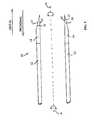
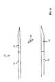
- FIG. 1is a perspective view of the present invention.
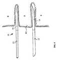
- FIG. 2is a close-up of the distal end of the present invention.
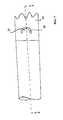
- FIG. 3is a sectional view of the distal end of the present invention.
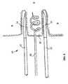
- FIG. 4is a sectional view of the distal end of the present invention showing in the present invention cutting into a bone.
- FIG. 5corresponds to FIG. 4, but shows a tissue removing insert anchored into a tissue mass protruding into the inner bore of the present invention.
- FIG. 6shows removal of the tissue mass from the inner bore of the invention.
- FIG. 7is a side elevation view of an embodiment of the invention having an inwardly facing projection in the drill bit.
- FIG. 8is a view corresponding to line 8 — 8 in FIG. 7 .
- FIG. 9is similar to FIG. 7, but shows the inwardly facing projection posed at an angle.
- FIG. 10shows an embodiment of the distal end of the present invention using a blade spanning across the inner bore of the drill bit.
- FIG. 11is a front view corresponding to FIG. 10 .
- FIG. 12is a view taken along line 12 — 12 in FIG. 11 .
- FIG. 13is a view taken along line 13 — 13 in FIG. 11 .
- FIG. 14is an illustration of the direction of travel of the present invention it moves between the tables of the ilium.
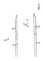
- FIG. 15is a side elevation view of the present invention.
- FIG. 16is a sectional view corresponding to line 16 — 16 in FIG. 15 .
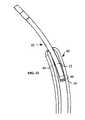
- FIG. 17is a side elevation view of the distal tip of the present invention.
- FIG. 18is a sectional view corresponding to line 18 in FIG. 17 .
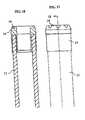
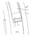
- FIG. 19is a side elevation view of the present invention.
- FIG. 20is a sectional view corresponding to line 20 — 20 in FIG. 19 .
- FIG. 21is a side elevation view corresponding to FIGS. 19 and 20.
- FIG. 22is a schematic view of the present drill positioned between the tables of the ilium.
- FIG. 23is a close-up view of corresponding to FIG. 22 .
- FIG. 24is a close-up view of corresponding to FIG. 23 .
- the present inventioncomprises a bone graft harvesting drill 10 comprised of a flexible tubular member 12 with a hollow cylindrical drill bit 14 mounted to the distal end of the flexible tubular member 12 as shown.
- the tubular member 12is made from a biocompatable thermoplastic such as polyethylene or polypropylene, however, many other plastics could be used.
- the drill bit 14is preferably made from stainless steel, however, other materials could be used, such as hard metals or hard thermoplastics.
- drill bit 14has a plurality of teeth 16 which wrap around its circumference.
- teeth 16are “wavy” or sinusoidal in shape as shown.
- An advantage of such a serrated toothis that it is non-clogging, as opposed to a typical triangular saw tooth, which has a tendency to catch materials in the spaces between the teeth.
- a further advantageis that the aggressiveness of the tip of the drill is more easily controlled in the serrated type tip than in more conventional saw tooth forms. If the bit becomes too aggressive, damage to the inner planes of the cortical bone may occur.
- the serrated type tipis much easier and more cost effective to manufacture than conventional saw tooth forms.
- Teeth 16have inner surfaces 15 and outer surfaces 17 .
- outer surfaces 17taper inwardly towards the distal end of drill 10 .
- Inner surfaces 15are preferably aligned parallel with one another and parallel with the outer surface of drill bit 14 as shown.
- FIG. 4shows drill 10 cutting into bone B.
- drill 10is rotated, about a central longitudinal axis A extending therethrough.
- a mass of bone tissue B 1will enter into the central bore of drill 10 as drill 10 is cut into the bone.
- a tissue removing insert 20is introduced into the central bore of drill 10 as shown in FIG. 5 .
- Insert 20may comprise a screw-type mechanism as illustrated, or any other system for gripping into and tearing away tissue mass B 1 .
- insert 20is used to tear away and remove tissue mass B 1 from the inner bore of drill 10 , such that tissue mass B 1 can be used as bone graft material.
- the sequence of steps illustrated in FIGS. 4, 5 , and 6can preferably be repeated again and again as drill 10 advances further and further into bone B.
- FIGS. 7 and 8An additional preferred aspect of the invention is illustrated in FIGS. 7 and 8 in which an inwardly facing projection 25 which may be formed by a C-shaped cut 26 in drill bit 14 is found. Specifically, as seen in FIG. 8, projection 25 is bent to face inwardly into the inner bore of drill 10 .
- An advantage of the projections 25 facing inwardlyare that as drill 10 is advanced, projections 25 will tend to tear away tissue protruding therein such that the tissue can easily be removed from the central bore of drill such that it can be used for bone graft purposes.
- a plurality of projections 25can be disposed around the circumference of drill bit 14 .
- such inwardly facing projections 25will be disposed equidistantly around the circumference of drill bit 14 .
- two, three, four or more of inwardly facing projections 25may be used.
- FIG. 9shows an inwardly facing projection 27 formed by a C-shaped cut 29 wherein projection 27 is disposed at an angle to axis A.
- An advantage of projection 27 being angled to axis Ais that it will tend to screw into the tissue mass disposed within the inner bore of drill 10 , such that the tissue mass can be more easily torn away and removed.
- FIG. 10shows an alternate embodiment of the present invention in which a blade 30 spans across the bore of drill bit 14 as shown.
- blade 30may comprise two sections 32 and 34 which may be oppositely angled such that as drill 10 is rotated, each of blades 32 and 34 cut into the tissue which becomes disposed within the inner bore of drill bit 14 such that the tissue can be easily removed from the inner bore of drill bit 14 .
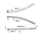
- FIGS. 14 and 22 to 24show a preferred direction of travel for drill 10 wherein drill 10 is introduced into ilium 40 into a region of cancellous bone 42 disposed between ilium tables 44 and 46 .
- Tables 44 and 46comprise a very hard cortical bone.
- drill bit 14will tend to be deflected along table 46 such that it cuts through cancellous bone 42 , without cutting through either 15 of tables 44 or 46 .
- tube 12being flexible such that it is able to respond to deflections of movement of drill bit 14 as drill 10 travels along path P as shown.
- FIGS. 20 and 21Bending of flexible tubular member 12 is also shown in FIGS. 20 and 21.
Landscapes
- Health & Medical Sciences (AREA)
- Life Sciences & Earth Sciences (AREA)
- Surgery (AREA)
- Public Health (AREA)
- Molecular Biology (AREA)
- Veterinary Medicine (AREA)
- General Health & Medical Sciences (AREA)
- Animal Behavior & Ethology (AREA)
- Engineering & Computer Science (AREA)
- Biomedical Technology (AREA)
- Heart & Thoracic Surgery (AREA)
- Medical Informatics (AREA)
- Orthopedic Medicine & Surgery (AREA)
- Dentistry (AREA)
- Oral & Maxillofacial Surgery (AREA)
- Transplantation (AREA)
- Nuclear Medicine, Radiotherapy & Molecular Imaging (AREA)
- Hematology (AREA)
- Immunology (AREA)
- Rheumatology (AREA)
- Pathology (AREA)
- Surgical Instruments (AREA)
Abstract
Description
Claims (14)
Priority Applications (2)
| Application Number | Priority Date | Filing Date | Title |
|---|---|---|---|
| US09/717,838US6764452B1 (en) | 1999-11-23 | 2000-11-21 | Bone graft harvester |
| US10/894,527US20040267268A1 (en) | 1999-11-23 | 2004-07-19 | Bone graft harvester and related methods |
Applications Claiming Priority (2)
| Application Number | Priority Date | Filing Date | Title |
|---|---|---|---|
| US16719299P | 1999-11-23 | 1999-11-23 | |
| US09/717,838US6764452B1 (en) | 1999-11-23 | 2000-11-21 | Bone graft harvester |
Related Child Applications (1)
| Application Number | Title | Priority Date | Filing Date |
|---|---|---|---|
| US10/894,527ContinuationUS20040267268A1 (en) | 1999-11-23 | 2004-07-19 | Bone graft harvester and related methods |
Publications (1)
| Publication Number | Publication Date |
|---|---|
| US6764452B1true US6764452B1 (en) | 2004-07-20 |
Family
ID=32684557
Family Applications (2)
| Application Number | Title | Priority Date | Filing Date |
|---|---|---|---|
| US09/717,838Expired - Fee RelatedUS6764452B1 (en) | 1999-11-23 | 2000-11-21 | Bone graft harvester |
| US10/894,527AbandonedUS20040267268A1 (en) | 1999-11-23 | 2004-07-19 | Bone graft harvester and related methods |
Family Applications After (1)
| Application Number | Title | Priority Date | Filing Date |
|---|---|---|---|
| US10/894,527AbandonedUS20040267268A1 (en) | 1999-11-23 | 2004-07-19 | Bone graft harvester and related methods |
Country Status (1)
| Country | Link |
|---|---|
| US (2) | US6764452B1 (en) |
Cited By (21)
| Publication number | Priority date | Publication date | Assignee | Title |
|---|---|---|---|---|
| US20030050574A1 (en)* | 2000-04-18 | 2003-03-13 | John Krueger | Bone biopsy instrument having improved sample retention |
| US20040267268A1 (en)* | 1999-11-23 | 2004-12-30 | Nuvasive, Inc. | Bone graft harvester and related methods |
| WO2006038862A1 (en)* | 2004-10-04 | 2006-04-13 | Vibratech Ab | An arrangement for taking a sample of bone marrow and/or evacuating the sinuses |
| US20070123894A1 (en)* | 2005-10-25 | 2007-05-31 | Claypool Jody L | Orthopaedic pin driver |
| US7798813B1 (en)* | 2007-11-20 | 2010-09-21 | Harrel Stephen K | Rotary tissue removing instrument |
| US20120053641A1 (en)* | 2010-08-24 | 2012-03-01 | Biomet Manufacturing Corp. | Cartilage Repair System With Flexible Trephine |
| WO2012015771A3 (en)* | 2010-07-30 | 2012-04-19 | Cook Medical Technologies Llc | Rotating full-core biopsy needle |
| CN103930065A (en)* | 2011-08-11 | 2014-07-16 | 奥齿泰有限责任公司 | Drill tool, drill tool cover and surgical instrument for harvesting autogenous bone using the drill tool and drill tool cover |
| US9216048B2 (en) | 2009-03-18 | 2015-12-22 | Integrated Spinal Concepts, Inc. | Image-guided minimal-step placement of screw into bone |
| US9451940B2 (en) | 2008-12-26 | 2016-09-27 | Pantheon Spinal, Llc | Method of retroperitoneal lateral insertion of spinal implants |
| CN109288553A (en)* | 2018-09-13 | 2019-02-01 | 张文君 | Medical orthopaedics punch |
| US10321833B2 (en) | 2016-10-05 | 2019-06-18 | Innovative Surgical Solutions. | Neural locating method |
| US10376209B2 (en) | 2013-09-20 | 2019-08-13 | Innovative Surgical Solutions, Llc | Neural locating method |
| US10376208B2 (en) | 2013-09-20 | 2019-08-13 | Innovative Surgical Solutions, Llc | Nerve mapping system |
| US10449002B2 (en) | 2013-09-20 | 2019-10-22 | Innovative Surgical Solutions, Llc | Method of mapping a nerve |
| US10478097B2 (en) | 2013-08-13 | 2019-11-19 | Innovative Surgical Solutions | Neural event detection |
| US10478096B2 (en) | 2013-08-13 | 2019-11-19 | Innovative Surgical Solutions. | Neural event detection |
| US10716553B2 (en) | 2017-04-19 | 2020-07-21 | Pantheon Spinal, Llc | Spine surgery retractor system and related methods |
| US10869616B2 (en) | 2018-06-01 | 2020-12-22 | DePuy Synthes Products, Inc. | Neural event detection |
| US10870002B2 (en) | 2018-10-12 | 2020-12-22 | DePuy Synthes Products, Inc. | Neuromuscular sensing device with multi-sensor array |
| US11399777B2 (en) | 2019-09-27 | 2022-08-02 | DePuy Synthes Products, Inc. | Intraoperative neural monitoring system and method |
Families Citing this family (9)
| Publication number | Priority date | Publication date | Assignee | Title |
|---|---|---|---|---|
| GB0204549D0 (en)* | 2002-02-27 | 2002-04-10 | Depuy Int Ltd | A surgical instrument system |
| DE202005016762U1 (en)* | 2005-10-26 | 2006-11-30 | Joimax Gmbh | Surgical milling cutter in particular for removal of tissue from facet joint at spine, comprises slightly widened front area |
| JP2008295901A (en)* | 2007-06-01 | 2008-12-11 | Wakayoshi Seisakusho Co Ltd | Instrument for collecting excised bone |
| USD576729S1 (en)* | 2007-10-29 | 2008-09-09 | Nakanishi, Inc. | Jawbone cutting instrument |
| USD584818S1 (en)* | 2008-03-06 | 2009-01-13 | Nakanishi Inc. | Jawbone cutting instrument |
| US9925068B2 (en) | 2014-05-30 | 2018-03-27 | Treace Medical Concepts, Inc. | Bone harvester and bone marrow removal system and method |
| CN109288554B (en)* | 2018-09-13 | 2021-06-08 | 青岛智兴医疗器械有限公司 | Drill bit for orthopedics |
| US10368880B1 (en)* | 2018-10-17 | 2019-08-06 | King Saud University | Universal base attachment bit and cutting bit assembly |
| WO2020247063A1 (en)* | 2019-06-05 | 2020-12-10 | Rivera Jose S Jr | Flexible trephine reamer |
Citations (15)
| Publication number | Priority date | Publication date | Assignee | Title |
|---|---|---|---|---|
| US4646738A (en) | 1985-12-05 | 1987-03-03 | Concept, Inc. | Rotary surgical tool |
| US5133755A (en) | 1986-01-28 | 1992-07-28 | Thm Biomedical, Inc. | Method and apparatus for diodegradable, osteogenic, bone graft substitute device |
| US5269785A (en) | 1990-06-28 | 1993-12-14 | Bonutti Peter M | Apparatus and method for tissue removal |
| US5322505A (en) | 1990-02-07 | 1994-06-21 | Smith & Nephew Dyonics, Inc. | Surgical instrument |
| US5411514A (en)* | 1992-09-30 | 1995-05-02 | Linvatec Corporation | Bendable variable angle rotating shaver |
| US5632747A (en) | 1995-03-15 | 1997-05-27 | Osteotech, Inc. | Bone dowel cutter |
| US5741261A (en) | 1996-06-25 | 1998-04-21 | Sdgi Holdings, Inc. | Minimally invasive spinal surgical methods and instruments |
| WO1998025539A1 (en) | 1996-12-13 | 1998-06-18 | Boettcher Robert | Device for sucking up and collecting bone particles |
| US5833692A (en)* | 1993-01-29 | 1998-11-10 | Smith & Nephew, Inc. | Surgical instrument |
| US5851208A (en) | 1996-10-15 | 1998-12-22 | Linvatec Corporation | Rotatable surgical burr |
| US5876405A (en)* | 1997-09-17 | 1999-03-02 | The Anspach Effort, Inc. | Perforator |
| US6030364A (en)* | 1997-10-03 | 2000-02-29 | Boston Scientific Corporation | Apparatus and method for percutaneous placement of gastro-intestinal tubes |
| WO2000045713A1 (en) | 1999-02-02 | 2000-08-10 | Synthes Ag Chur | Device with a flexible shaft for removing bone grafts |
| WO2000045712A1 (en) | 1999-02-02 | 2000-08-10 | Synthes Ag Chur | Device for removing bone grafts |
| US6179615B1 (en)* | 1999-03-26 | 2001-01-30 | Gordon D. Blacklock | Dental drill with integral guide |
Family Cites Families (6)
| Publication number | Priority date | Publication date | Assignee | Title |
|---|---|---|---|---|
| US3783860A (en)* | 1972-10-27 | 1974-01-08 | Sampson Corp | Intramedullary rod |
| DE2838348C2 (en)* | 1978-09-02 | 1982-10-28 | Hans Gustav 7130 Mühlacker Neuhäuser | Device for forming a bone opening |
| US4362161A (en)* | 1980-10-27 | 1982-12-07 | Codman & Shurtleff, Inc. | Cranial drill |
| US5122134A (en)* | 1990-02-02 | 1992-06-16 | Pfizer Hospital Products Group, Inc. | Surgical reamer |
| US6450948B1 (en)* | 1999-11-02 | 2002-09-17 | Vista Medical Technologies, Inc. | Deflecting tip for surgical cannula |
| US6764452B1 (en)* | 1999-11-23 | 2004-07-20 | Nuvasive, Inc. | Bone graft harvester |
- 2000
- 2000-11-21USUS09/717,838patent/US6764452B1/ennot_activeExpired - Fee Related
- 2004
- 2004-07-19USUS10/894,527patent/US20040267268A1/ennot_activeAbandoned
Patent Citations (15)
| Publication number | Priority date | Publication date | Assignee | Title |
|---|---|---|---|---|
| US4646738A (en) | 1985-12-05 | 1987-03-03 | Concept, Inc. | Rotary surgical tool |
| US5133755A (en) | 1986-01-28 | 1992-07-28 | Thm Biomedical, Inc. | Method and apparatus for diodegradable, osteogenic, bone graft substitute device |
| US5322505A (en) | 1990-02-07 | 1994-06-21 | Smith & Nephew Dyonics, Inc. | Surgical instrument |
| US5269785A (en) | 1990-06-28 | 1993-12-14 | Bonutti Peter M | Apparatus and method for tissue removal |
| US5411514A (en)* | 1992-09-30 | 1995-05-02 | Linvatec Corporation | Bendable variable angle rotating shaver |
| US5833692A (en)* | 1993-01-29 | 1998-11-10 | Smith & Nephew, Inc. | Surgical instrument |
| US5632747A (en) | 1995-03-15 | 1997-05-27 | Osteotech, Inc. | Bone dowel cutter |
| US5741261A (en) | 1996-06-25 | 1998-04-21 | Sdgi Holdings, Inc. | Minimally invasive spinal surgical methods and instruments |
| US5851208A (en) | 1996-10-15 | 1998-12-22 | Linvatec Corporation | Rotatable surgical burr |
| WO1998025539A1 (en) | 1996-12-13 | 1998-06-18 | Boettcher Robert | Device for sucking up and collecting bone particles |
| US5876405A (en)* | 1997-09-17 | 1999-03-02 | The Anspach Effort, Inc. | Perforator |
| US6030364A (en)* | 1997-10-03 | 2000-02-29 | Boston Scientific Corporation | Apparatus and method for percutaneous placement of gastro-intestinal tubes |
| WO2000045713A1 (en) | 1999-02-02 | 2000-08-10 | Synthes Ag Chur | Device with a flexible shaft for removing bone grafts |
| WO2000045712A1 (en) | 1999-02-02 | 2000-08-10 | Synthes Ag Chur | Device for removing bone grafts |
| US6179615B1 (en)* | 1999-03-26 | 2001-01-30 | Gordon D. Blacklock | Dental drill with integral guide |
Cited By (46)
| Publication number | Priority date | Publication date | Assignee | Title |
|---|---|---|---|---|
| US20040267268A1 (en)* | 1999-11-23 | 2004-12-30 | Nuvasive, Inc. | Bone graft harvester and related methods |
| US20030050574A1 (en)* | 2000-04-18 | 2003-03-13 | John Krueger | Bone biopsy instrument having improved sample retention |
| US7201722B2 (en) | 2000-04-18 | 2007-04-10 | Allegiance Corporation | Bone biopsy instrument having improved sample retention |
| WO2006038862A1 (en)* | 2004-10-04 | 2006-04-13 | Vibratech Ab | An arrangement for taking a sample of bone marrow and/or evacuating the sinuses |
| US20070270712A1 (en)* | 2004-10-04 | 2007-11-22 | Vibratech Ab | Arrangement for Taking a Sample of Bone Marrow and/or Evacuating the Sinuses |
| US20070123894A1 (en)* | 2005-10-25 | 2007-05-31 | Claypool Jody L | Orthopaedic pin driver |
| US7819876B2 (en) | 2005-10-25 | 2010-10-26 | Zimmer Technology, Inc. | Orthopaedic pin driver |
| US7798813B1 (en)* | 2007-11-20 | 2010-09-21 | Harrel Stephen K | Rotary tissue removing instrument |
| US11969359B2 (en) | 2008-12-26 | 2024-04-30 | Pantheon Spinal, Llc | Method of retroperitoneal lateral insertion of spinal implants |
| US10085854B2 (en) | 2008-12-26 | 2018-10-02 | Pantheon Spinal, Llc | Method of retroperitoneal lateral insertion of spinal implants |
| US12383411B2 (en) | 2008-12-26 | 2025-08-12 | Pantheon Spinal, Llc | Spinal surgery methods and devices |
| US9451940B2 (en) | 2008-12-26 | 2016-09-27 | Pantheon Spinal, Llc | Method of retroperitoneal lateral insertion of spinal implants |
| US10959860B2 (en) | 2008-12-26 | 2021-03-30 | Pantheon Spinal, Llc | Method of retroperitoneal lateral insertion of spinal implants |
| US11471220B2 (en) | 2009-03-18 | 2022-10-18 | Integrated Spinal Concepts, Inc. | Image-guided minimal-step placement of screw into bone |
| US9216048B2 (en) | 2009-03-18 | 2015-12-22 | Integrated Spinal Concepts, Inc. | Image-guided minimal-step placement of screw into bone |
| US9687306B2 (en) | 2009-03-18 | 2017-06-27 | Integrated Spinal Concepts, Inc. | Image-guided minimal-step placement of screw into bone |
| US10603116B2 (en) | 2009-03-18 | 2020-03-31 | Integrated Spinal Concepts, Inc. | Image-guided minimal-step placement of screw into bone |
| WO2012015771A3 (en)* | 2010-07-30 | 2012-04-19 | Cook Medical Technologies Llc | Rotating full-core biopsy needle |
| US9149293B2 (en) | 2010-07-30 | 2015-10-06 | Cook Medical Technologies Llc | Rotating full-core biopsy needle |
| US11382607B2 (en) | 2010-07-30 | 2022-07-12 | Cook Medical Technologies Llc | Rotating full-core biopsy needle |
| US9763649B2 (en) | 2010-07-30 | 2017-09-19 | Cook Medical Technologies Llc | Rotating full-core biopsy needle |
| US8801716B2 (en)* | 2010-08-24 | 2014-08-12 | Biomet Manufacturing, Llc | Cartilage repair system with flexible trephine |
| US20120053641A1 (en)* | 2010-08-24 | 2012-03-01 | Biomet Manufacturing Corp. | Cartilage Repair System With Flexible Trephine |
| US9572686B2 (en) | 2010-08-24 | 2017-02-21 | Biomet Manufacturing, Llc | Cartilage repair system with flexible trephine |
| TWI489978B (en)* | 2011-08-11 | 2015-07-01 | Osstem Implant Co Ltd | Drill and drill cover and autogenous bone collector using the same |
| CN103930065B (en)* | 2011-08-11 | 2017-06-23 | 奥齿泰有限责任公司 | Drilling tool, drilling tool cover and use the drilling tool and the operating theater instruments for collecting autologous bone of drilling tool cover |
| CN103930065A (en)* | 2011-08-11 | 2014-07-16 | 奥齿泰有限责任公司 | Drill tool, drill tool cover and surgical instrument for harvesting autogenous bone using the drill tool and drill tool cover |
| US9888929B2 (en) | 2011-08-11 | 2018-02-13 | Osstemimplant Co., Ltd. | Drill, drill cover, and surgical instrument for collecting autologous bone employing same |
| US10478097B2 (en) | 2013-08-13 | 2019-11-19 | Innovative Surgical Solutions | Neural event detection |
| US10478096B2 (en) | 2013-08-13 | 2019-11-19 | Innovative Surgical Solutions. | Neural event detection |
| US10376208B2 (en) | 2013-09-20 | 2019-08-13 | Innovative Surgical Solutions, Llc | Nerve mapping system |
| US10449002B2 (en) | 2013-09-20 | 2019-10-22 | Innovative Surgical Solutions, Llc | Method of mapping a nerve |
| US10376209B2 (en) | 2013-09-20 | 2019-08-13 | Innovative Surgical Solutions, Llc | Neural locating method |
| US12109042B2 (en) | 2016-10-05 | 2024-10-08 | Innovative Surgical Solutions, Llc | Neural locating system and method |
| US10321833B2 (en) | 2016-10-05 | 2019-06-18 | Innovative Surgical Solutions. | Neural locating method |
| US11311222B2 (en) | 2016-10-05 | 2022-04-26 | Innovative Surgical Solutions | Neural locating system |
| US11963674B2 (en) | 2017-04-19 | 2024-04-23 | Pantheon Spinal, Llc | Spine surgery retractor system and related methods |
| US11478237B2 (en) | 2017-04-19 | 2022-10-25 | Pantheon Spinal, Llc | Spine surgery retractor system and related methods |
| US10716553B2 (en) | 2017-04-19 | 2020-07-21 | Pantheon Spinal, Llc | Spine surgery retractor system and related methods |
| US10869616B2 (en) | 2018-06-01 | 2020-12-22 | DePuy Synthes Products, Inc. | Neural event detection |
| CN109288553B (en)* | 2018-09-13 | 2021-06-15 | 赵斌 | Medical bone perforator |
| CN109288553A (en)* | 2018-09-13 | 2019-02-01 | 张文君 | Medical orthopaedics punch |
| US10870002B2 (en) | 2018-10-12 | 2020-12-22 | DePuy Synthes Products, Inc. | Neuromuscular sensing device with multi-sensor array |
| US12090320B2 (en) | 2018-10-12 | 2024-09-17 | DePuy Synthes Products, Inc. | Neuromuscular sensing device with multi-sensor array |
| US11399777B2 (en) | 2019-09-27 | 2022-08-02 | DePuy Synthes Products, Inc. | Intraoperative neural monitoring system and method |
| US12303301B2 (en) | 2019-09-27 | 2025-05-20 | DePuy Synthes Products, Inc. | Intraoperative neural monitoring system and method |
Also Published As
| Publication number | Publication date |
|---|---|
| US20040267268A1 (en) | 2004-12-30 |
Similar Documents
| Publication | Publication Date | Title |
|---|---|---|
| US6764452B1 (en) | Bone graft harvester | |
| US6302885B1 (en) | Bone nail | |
| US5084052A (en) | Surgical cutting instrument with plurality of openings | |
| US11337709B2 (en) | Drill bit and method for producing a drill bit | |
| US10405872B2 (en) | Cutting head for an intramedullary reamer | |
| US11523835B2 (en) | Arthroscopic drill blade and arthroscopic drill access system made therefrom | |
| US4473070A (en) | Intramedullary reamer | |
| US6312432B1 (en) | Bone drill | |
| US5334204A (en) | Fixation screw | |
| US4844064A (en) | Surgical cutting instrument with end and side openings | |
| US8460298B2 (en) | Surgical bur with unequally spaced flutes, flutes with different rake angles and flutes with alternating reliefs | |
| US9687267B2 (en) | Device for cutting tissue | |
| EP2068729B1 (en) | Cutting blade for morcellator | |
| US5026386A (en) | Flaval separator | |
| WO2010050252A1 (en) | Bone fixing material and thighbone fixing system | |
| EP3629946B1 (en) | An ultrasonic cutting device for osteotomy | |
| JP2019505320A (en) | Minimally invasive cutting instrument with guided incision device for multiple applications | |
| US5968048A (en) | Bore head for boring bone channels | |
| CN1273089C (en) | Surgical reamer | |
| JP5000218B2 (en) | Humeral nail | |
| JPH09149907A (en) | Bone fixing tool, and bone fixing system | |
| US20190350613A1 (en) | Dental cutting tool | |
| KR101979106B1 (en) | A Minimum Invasion Type of a Medical Cutter Tool for Cutting a Part of Articulation Used in an Orthopedic Operation | |
| EP4505955A1 (en) | Bone removing device | |
| NL9201046A (en) | Tool for removing a bone pin |
Legal Events
| Date | Code | Title | Description |
|---|---|---|---|
| AS | Assignment | Owner name:NUVASIVE, INC., CALIFORNIA Free format text:ASSIGNMENT OF ASSIGNORS INTEREST;ASSIGNORS:GILLESPIE, WALTER D.;MATSUURA, DAVID G.;MARINO, JAMES F.;AND OTHERS;REEL/FRAME:011834/0573;SIGNING DATES FROM 20001228 TO 20001231 | |
| FPAY | Fee payment | Year of fee payment:4 | |
| AS | Assignment | Owner name:NUVASIVE, INC., CALIFORNIA Free format text:CHANGE OF ADDRESS;ASSIGNOR:NUVASIVE, INC.;REEL/FRAME:022706/0920 Effective date:20080811 | |
| FEPP | Fee payment procedure | Free format text:PAT HOLDER NO LONGER CLAIMS SMALL ENTITY STATUS, ENTITY STATUS SET TO UNDISCOUNTED (ORIGINAL EVENT CODE: STOL); ENTITY STATUS OF PATENT OWNER: LARGE ENTITY | |
| FPAY | Fee payment | Year of fee payment:8 | |
| SULP | Surcharge for late payment | ||
| REMI | Maintenance fee reminder mailed | ||
| LAPS | Lapse for failure to pay maintenance fees | ||
| STCH | Information on status: patent discontinuation | Free format text:PATENT EXPIRED DUE TO NONPAYMENT OF MAINTENANCE FEES UNDER 37 CFR 1.362 | |
| FP | Lapsed due to failure to pay maintenance fee | Effective date:20160720 | |
| AS | Assignment | Owner name:BANK OF AMERICA, N.A., AS ADMINISTRATIVE AGENT, CALIFORNIA Free format text:NOTICE OF GRANT OF SECURITY INTEREST IN PATENTS;ASSIGNORS:NUVASIVE, INC.;IMPULSE MONITORING, INC.;REEL/FRAME:040634/0404 Effective date:20160208 Owner name:BANK OF AMERICA, N.A., AS ADMINISTRATIVE AGENT, CA Free format text:NOTICE OF GRANT OF SECURITY INTEREST IN PATENTS;ASSIGNORS:NUVASIVE, INC.;IMPULSE MONITORING, INC.;REEL/FRAME:040634/0404 Effective date:20160208 | |
| AS | Assignment | Owner name:BANK OF AMERICA, N.A., AS ADMINISTRATIVE AGENT, TE Free format text:NOTICE OF GRANT OF SECURITY INTEREST IN PATENTS;ASSIGNORS:NUVASIVE, INC.;BIOTRONIC NATIONAL, LLC;NUVASIVE CLINICAL SERVICES MONITORING, INC.;AND OTHERS;REEL/FRAME:042490/0236 Effective date:20170425 Owner name:BANK OF AMERICA, N.A., AS ADMINISTRATIVE AGENT, TEXAS Free format text:NOTICE OF GRANT OF SECURITY INTEREST IN PATENTS;ASSIGNORS:NUVASIVE, INC.;BIOTRONIC NATIONAL, LLC;NUVASIVE CLINICAL SERVICES MONITORING, INC.;AND OTHERS;REEL/FRAME:042490/0236 Effective date:20170425 | |
| AS | Assignment | Owner name:BANK OF AMERICA, N.A., AS ADMINISTRATIVE AGENT, NORTH CAROLINA Free format text:SECURITY INTEREST;ASSIGNORS:NUVASIVE, INC.;NUVASIVE CLINICAL SERVICES MONITORING, INC.;NUVASIVE CLINICAL SERVICES, INC.;AND OTHERS;REEL/FRAME:052918/0595 Effective date:20200224 |