US6764389B1 - Conditioning bar assembly having an abrasion member supported on a polycarbonate member - Google Patents
Conditioning bar assembly having an abrasion member supported on a polycarbonate memberDownload PDFInfo
- Publication number
- US6764389B1 US6764389B1US10/224,025US22402502AUS6764389B1US 6764389 B1US6764389 B1US 6764389B1US 22402502 AUS22402502 AUS 22402502AUS 6764389 B1US6764389 B1US 6764389B1
- Authority
- US
- United States
- Prior art keywords
- polycarbonate
- conditioning
- elongate
- polycarbonate member
- abrasion
- Prior art date
- Legal status (The legal status is an assumption and is not a legal conclusion. Google has not performed a legal analysis and makes no representation as to the accuracy of the status listed.)
- Expired - Lifetime
Links
- 230000003750conditioning effectEffects0.000titleclaimsabstractdescription114
- 239000004417polycarbonateSubstances0.000titleclaimsabstractdescription92
- 229920000515polycarbonatePolymers0.000titleclaimsabstractdescription92
- 238000005299abrasionMethods0.000titleclaimsabstractdescription29
- 239000002184metalSubstances0.000claimsabstractdescription33
- 238000005498polishingMethods0.000claimsdescription54
- 239000002002slurrySubstances0.000claimsdescription20
- 239000000463materialSubstances0.000claimsdescription12
- 239000000126substanceSubstances0.000claimsdescription12
- 229910003460diamondInorganic materials0.000claimsdescription10
- 239000010432diamondSubstances0.000claimsdescription10
- 230000014759maintenance of locationEffects0.000claimsdescription8
- 239000004033plasticSubstances0.000claimsdescription8
- 238000000034methodMethods0.000claimsdescription6
- 239000002245particleSubstances0.000claimsdescription6
- 230000000694effectsEffects0.000claimsdescription5
- 230000013011matingEffects0.000claims1
- 235000012431wafersNutrition0.000description21
- 229910000831SteelInorganic materials0.000description9
- 239000010959steelSubstances0.000description9
- VYPSYNLAJGMNEJ-UHFFFAOYSA-NSilicium dioxideChemical compoundO=[Si]=OVYPSYNLAJGMNEJ-UHFFFAOYSA-N0.000description4
- 239000006260foamSubstances0.000description4
- 210000004712air sacAnatomy0.000description3
- 238000009428plumbingMethods0.000description3
- 230000002787reinforcementEffects0.000description3
- 239000004065semiconductorSubstances0.000description3
- 239000000853adhesiveSubstances0.000description2
- 230000001070adhesive effectEffects0.000description2
- 230000015556catabolic processEffects0.000description2
- 238000006731degradation reactionMethods0.000description2
- 238000009826distributionMethods0.000description2
- 238000004519manufacturing processMethods0.000description2
- 235000012239silicon dioxideNutrition0.000description2
- 239000000377silicon dioxideSubstances0.000description2
- 229920004943Delrin®Polymers0.000description1
- 239000003082abrasive agentSubstances0.000description1
- 230000001154acute effectEffects0.000description1
- 238000004026adhesive bondingMethods0.000description1
- 230000000295complement effectEffects0.000description1
- 230000001143conditioned effectEffects0.000description1
- 238000010586diagramMethods0.000description1
- 239000000835fiberSubstances0.000description1
- 238000002347injectionMethods0.000description1
- 239000007924injectionSubstances0.000description1
- 238000005304joiningMethods0.000description1
- 238000001465metallisationMethods0.000description1
- 230000000737periodic effectEffects0.000description1
- 239000000758substrateSubstances0.000description1
Images


Classifications
- B—PERFORMING OPERATIONS; TRANSPORTING
- B24—GRINDING; POLISHING
- B24B—MACHINES, DEVICES, OR PROCESSES FOR GRINDING OR POLISHING; DRESSING OR CONDITIONING OF ABRADING SURFACES; FEEDING OF GRINDING, POLISHING, OR LAPPING AGENTS
- B24B53/00—Devices or means for dressing or conditioning abrasive surfaces
- B24B53/017—Devices or means for dressing, cleaning or otherwise conditioning lapping tools
- B—PERFORMING OPERATIONS; TRANSPORTING
- B24—GRINDING; POLISHING
- B24B—MACHINES, DEVICES, OR PROCESSES FOR GRINDING OR POLISHING; DRESSING OR CONDITIONING OF ABRADING SURFACES; FEEDING OF GRINDING, POLISHING, OR LAPPING AGENTS
- B24B53/00—Devices or means for dressing or conditioning abrasive surfaces
- B24B53/12—Dressing tools; Holders therefor
Definitions
- the present inventionrelates generally to chemical mechanical planarization of semiconductors, and more particularly, to methods and apparatus for conditioning polishing pads used in chemical mechanical planarization.
- CMPchemical mechanical planarization or chemical mechanical polishing
- CMPinvolves mounting a semiconductor wafer on a fixture and rotating the wafer face against a polishing pad.
- the polishing padis typically mounted on a moving platen, thereby effecting multiple directions of movement between the rotating wafer and the polishing pad.
- a slurry containing an abrasive and a chemical that chemically interacts with the wafer faceis flowed between the wafer and the polishing pad.
- CMPis commonly applied to planarize dielectric layers, metallization layers, and other wafer layers.
- FIG. 1shows some major components of a typical CMP apparatus. Examples of such apparatuses are known in the art and are available, for example, from SpeedfamIPEC of Chandler, Ariz.
- the CMP apparatus 100includes a wafer carrier 128 that is fitted with an air chamber 126 (shown in phantom lines), which is designed to secure a wafer 124 by vacuum to the wafer carrier 128 during wafer loading typically before the CMP is to commence.
- the wafer 124is bound by “wear rings”, not shown, within the wafer carrier 128 such that a wafer surface that is to be polished contacts a polishing pad 102 .
- the polishing pad 102orbits while the wafer 124 rotates.
- a conventional polishing pad 102 for use with an apparatus such as illustrated in FIG. 1includes a plurality of slurry injection holes 120 , and adheres to a flexible pad backing 104 which includes a plurality of corresponding pad backing holes 118 .
- a slurry mesh 106typically in the form of a screen-like structure, is positioned below the pad backing 104 .
- An air bladder 108 capable of inflating or deflatingis disposed between a plumbing reservoir 110 and the slurry mesh 106 . The air bladder 108 pressurizes to apply the polishing force.
- a co-axial shaft 112through which a slurry inlet 114 (shown by phantom lines) is provided to deliver slurry through the plumbing reservoir 110 and the air bladder 108 to the slurry mesh 106 , is attached to the bottom of plumbing reservoir 110 .
- Slurryis delivered to the system by an external low pressure pump, and is distributed on the polishing pad surface by centripetal force, the polishing action, and slurry pressure distribution on the pad 102 .
- the polishing pad 102may also be provided with grooves or perforations (not shown) for slurry distribution and improved pad-wafer contact.
- pad glazingresults when particles that have eroded from the wafer surface, along with the abrasives from the slurry, tend to glaze or accumulate over the polishing pad.
- a glazed layer on the polishing padtypically forms atop the eroded wafer and slurry particles that are embedded in the porosity or fibers of the polishing pad.
- Pad glazingis particularly pronounced during planarization of an oxide layer such as a silicon dioxide layer (hereinafter referred to as “oxide CMP”).
- Pad glazingis undesirable because it reduces the polishing rate of the wafer surface and produces a non-uniformly polished wafer surface. The non-uniformity results because glazed layers are often unevenly distributed over a polishing pad surface.
- One way of achieving and maintaining a high and stable polishing rateis by conditioning the polishing pad on a regular basis.
- the polishing padmay be conditioned every time after a wafer has been polished.
- an abrasive conditioning bar or an abrasive diskis typically contacted with the polishing pad, which may be rotating or in an orbital movement.
- One type of conditioning operationemploys a conditioning bar that swept across the face of rotating polishing pad.
- the conditioning baris mounted on a mounting element and includes an abrasive surface.
- the mounting elementimparts pivotal or linear movement to the conditioning bar.
- the abrasive surfacewhich often includes diamond particles, operates to condition the polishing pad through the relative motion of the conditioning bar and the polishing pad.
- One problem with current conditioning operationsis the relatively short life of the conditioning bars.
- One type of conditioning bar that is commonly usedincludes a diamond tape or strip that is wrapped over a flexible foam support.
- the diamond stripmay be readily replace as the abrasiveness of the strip degrades.
- the CMP slurryalso tends to degrade the flexible foam support.
- the harsh chemical environment created by the slurrycauses degradation of the flexible foam support, thereby mandating relatively frequent replacement.
- An alternative designemploys rigid steel bar with diamond grid plates adhered to the steel bar.
- the rigid steel bar designis relatively expensive to manufacture and handle.
- providing fixturing features and/or adhering the grid platesrequires tooling and processing steps specific to steel.
- the rigid steel baris not impervious to the slurry chemicals.
- the present inventionaddresses the above stated needs, as well as others, by providing a conditioning bar that uses a polycarbonate support member on which is supported an abrasion member.
- the polycarbonate support memberis reinforced by a rigid metal element, with the polycarbonate member disposed at least in part between the abrasion member and the rigid metal element.
- the expense associated with a complex shaped and formed steel conditioning baris avoided.
- the metal reinforcement elementneed only be a simple bar or rod, which is relatively inexpensive to form.
- the exposure of the metal reinforcement to slurry chemicalsis limited by the polycarbonate member, thereby reducing possibility for degradation.
- a first embodiment of the inventionis a conditioning bar assembly that includes a polycarbonate member, an abrasion member, and a rigid metal element.
- the abrasion memberis supported on an outer surface of the polycarbonate member.
- the rigid metal elementis supported on the polycarbonate member, at least a portion of the polycarbonate member disposed between the rigid metal element and at least a portion of the abrasion member.
- a conditioning bar assemblythat includes an elongate polycarbonate member and an abrasion member.
- the elongate polycarbonate memberis constructed of an inert plastic material.
- the abrasion memberis removably supported on at least one side of the elongate polycarbonate member.
- the abrasion memberis an abrasive tape, but may also include abrasive grid plates.
- FIG. 1shows a cross-sectional view of a typical chemical mechanical polishing or planarization apparatus
- FIG. 2shows a top plan view of an exemplary conditioning bar assembly according to the present invention performing conditioning on a polishing pad
- FIG. 3shows a front plant view of the conditioning bar assembly and polishing pad of FIG. 2;
- FIG. 4shows a perspective view of the conditioning bar and the conditioning bar housing of the conditioning bar assembly of FIG. 2 apart from the other elements of the conditioning bar assembly and the polishing pad of FIG. 2;
- FIG. 5shows a partially exploded, perspective view of the conditioning bar and conditioning bar housing of FIG. 4;
- FIG. 6shows an exploded side plan view of the conditioning bar and conditioning bar housing of FIG. 5;
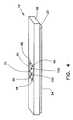
- FIG. 7shows an exploded, sectional view of the support bar of the conditioning bar of FIG. 6;
- FIG. 8shows an exploded, end plan view of a conditioning bar according to an alternative embodiment of the invention.
- FIG. 9shows an exploded, sectional view of an alternative support bar of the conditioning bar of FIG. 6 .
- FIGS. 2 and 3illustrate a conditioning operation according to the present invention from different view points.
- a conditioning bar assembly 10that includes a first embodiment of a conditioning bar 12 according to the present invention operates to condition a CMP polishing pad 20 affixed to a rotating platen 22 .
- the conditioning bar 12is disposed against the surface of the polishing pad 20 and abrasive particles on the conditioning bar 12 scrape or abrade the polishing pad 20 .
- the conditioning bar assembly 10further includes a mounting element 14 on which the conditioning bar 12 is supported.
- the mounting element 14operates to support the conditioning bar 12 and move the conditioning bar 12 over the surface of the rotating polishing pad 20 .
- the mounting element 14may take many forms, in the exemplary embodiment described herein the mounting element 14 includes a pivoting support arm 16 and a conditioning bar housing 18 .
- the conditioning bar housing 18extends in an elongate manner preferably somewhat coextensive with the conditioning bar 12 to provide a sturdy mounting fixture therefor.
- the pivoting arm 16is configured to be coupled to a connection extension 70 of the conditioning bar housing 18 .
- the pivoting arm 16includes a pivoting end 24 and an opposite end, the opposite end connected to the connectoin extension 70 . In operation, the pivoting arm 16 moves pivotally back and forth about the pivoting end 24 such that the conditioning bar 12 coupled to the conditioning bar housing 18 sweeps over the entire surface of the polishing pad 20 .
- mounting elementsmay be employed, including those that use other types of movement, such as linear or rotational movement.
- the mounting elementmay hold the conditioning bar may be stationery.
- the conditioning bar 12thus sweeps over the rotating polishing pad 20 , thereby conditioning the polishing pad 20 for use in a subsequent CMP polishing operation. It is noted that FIG. 3 shows the conditioning bar 12 spaced apart from the polishing pad 20 only as a result of the partially exploded nature of the diagram. In actual use, the conditioning bar 12 engages the polishing pad 20 surface as discussed above.
- FIGS. 4, 5 and 6show in further detail different views of an exemplary conditioning bar 12 and an exemplary conditioning bar housing 18 .
- the conditioning bar 12 and the conditioning bar housing 18are illustrated in FIGS. 4, 5 and 6 apart from the polishing pad 20 and pivoting support arm 16 .
- FIG. 4shows a perspective view of the conditioning bar 12 assembled into the conditioning bar housing 18
- FIG. 5shows a partially exploded perspective view wherein the conditioning bar 12 is spaced apart form the conditioning bar housing 18
- FIG. 6shows an exploded side plan view of both the conditioning bar 12 and the conditioning bar housing 18 .
- FIG. 7shows a cutaway perspective view of the polycarbonate support bar 26 of the conditioning bar 12 .
- FIG. 9shows an alternative embodiment of the polycarbonate support bar 26 .
- the conditioning bar 12includes the support bar 26 and an abrasion member, which in the embodiment described herein comprises an abrasive strip or tape 34 .
- the support bar 26comprises a first polycarbonate member 28 secured to a second polycarbonate member 30 .
- a rigid metal element 32is disposed in a hollow cavity 36 that is formed between the first and second polycarbonate members 28 and 30 when they are assembled together.
- the abrasive tape 34is affixed as an outer surface of the conditioning bar 12 .
- the abrasive tape 34is a strip of flexible material on which is adhered diamond grit.
- Such tape or stripis well known in the art, and may suitably be a diamond abrasive strip, available from 3M Co.
- the first polycarbonate member 28is an elongate structure having a consistent cross-sectional shape throughout its length. As shown in FIG. 6, the first polycarbonate includes a rounded support surface 38 that extends through the entire length of the member 28 .
- the rounded support surface 28defines the bottom and side surfaces of the member while the top surface is defined by dovetail features 42 and a lower cavity 40 .
- the lower cavity 40defines a portion, and preferably half, of the hollow cavity 36 that receives the rigid metal element 32 . Extending from either side of the lower cavity to the ends of the rounded support surface 28 are the dovetail features 42 .
- the dovetail features 42are stepped horizontal surface preferably connected by an acute-angled surface.
- the dovetail features 42are configured to engage complementary features on the second polycarbonate member 30 as a mechanical retention means, as will be discussed below.
- the second polycarbonate member 30is also an elongate structure also preferably having a consistent cross-sectional shape throughout its length.
- the first polycarbonate member 28 and the second polycarbonate member 30are preferably the same length and same approximate width, as shown in FIGS. 5 and 6.
- the second polycarbonate memberincludes two opposite upright support surfaces 50 defining the sides thereof.
- the two opposite upright surfaces 50are configured to form a relatively continuous surface with the rounded support surface 28 when the support bar 26 is fully assembled (see e.g. FIG. 5 ).
- the top surface of the second polycarbonate member 30includes two extensions 44 and 46 extending upward from, respectively, the two upright surfaces 50 .
- the two extensions 44 , 46extend upward from the main central portion of the top of the second member to define a channel 48 therebetween.
- the bottom surface of the second polycarbonate member 30includes an upper cavity 52 and opposite dovetail features 54 .
- the upper cavity 52defines a portion, preferably half, of the hollow cavity 36 that receives the rigid metal element 32 .
- Extending from either side of the upper cavity 52 and to the bottom ends of the upright support surfaces 50are the dovetail features 54 .
- the dovetail features 54are configured to complementarily engage the dovetail features 42 of the first polycarbonate member 28 .
- the dovetail features 54may similarly comprise stepped horizontal surface connected by an acute, angled surface.
- both the first and second polycarbonate members 28 , 30are constructed of an inert plastic material.
- the inert plastic materialis preferably inert to common industrial slurries.
- the plastic materialpreferably has inert qualities for pH levels of 2 to approximately 11.
- suitable inert materialsinclude Delrin and Ertalyte, both of which are available from DuPont. Those of ordinary skill in the art may readily determine other suitable plastic materials that exhibit the required structural and chemically inert qualities.
- the abrasive tape 34extends longitudinally along the length of the support bar 26 .
- the abrasive tape 34has a width that extends between substantially parallel opposing edges 72 and 74 .
- the first edge 72is disposed at least partially within the channel 48 .
- the remainder of the abrasive tape 34extends, preferably tightly, from the first edge 72 over the first extension 44 , down the adjoining upright support surface 50 , around the rounded support surface 38 , up the other upright support surface 50 , over the second extension 46 , and at least partly into the channel 48 .
- the second edge 74also extends at least partially into the channel 48 .
- the abrasive tape 34is held in place through a clamping force exerted by the mounting bar 56 (see below) when the mounting bar 56 is disposed within the channel 48 .
- the mounting bar 56is a portion of the conditioning bar housing 18 discussed further below.
- the abrasive tape 34may be arranged in other ways, so long as it substantially covers the bottom portions of the support bar 16 and is securely fastened onto the support bar 16 .
- the edges 72 and 74 of the abrasive tape 34may instead be trapped between the first and second polycarbonate members 28 and 30 .
- the embodiment illustrated in FIG. 6has additional advantages of providing an easy changeout.
- FIG. 9shows a perspective exploded view of two polycarbonate members 28 ′ and 30 ′ that combine to form support bar 26 ′ similar to the support bar 26 .
- the polycarbonate member 28 ′includes retention extensions 82 that extend upward from the top surface thereof.
- the retention extensions 82do not necessarily extend the length of the polycarbonate member 28 ′.
- the other polycarbonate member 30 ′includes corresponding openings 84 for receiving the retention extensions 82 .
- the retention extensionspreferably include barbs or overhangs 86 that engage ledges, not shown, in the openings 84 to retain the retention extensions 82 therein.
- the retention extensionsare inserted into the openings 84 until the overhangs 86 snap into place.
- the rigid metal element 32may optionally be inserted prior to assembling the support bar 26 ′.
- the support bar 26may suitably be formed as a single, integral piece having an interior bore for receiving the rigid metal element 34 .
- conditioning bar housing 18may take a plurality of forms without departing from the spirit and scope of the present invention.
- the embodiment shown in FIGS. 4, 5 and 6are given by way of example only.
- the conditioning bar housing 18includes the mounting bar 56 , a top support 58 , and a connector plate 60 .
- the mounting bar 56is a generally elongate rectangular piece having a rectangular cross section. In general, the mounting bar 56 has a configuration that is intended to fit snugly within the channel 48 of the conditioning bar 12 . Accordingly, in alternative designs, the mounting bar 56 may have cross sections of other shapes, provided that the channel 48 has a corresponding shape.
- the mounting bar 56is preferably constructed of steel or another rigid material.
- the top support 58is preferably an elongate plastic rectangular element. Coupled to the top support 58 is the connector plate 60 .
- the connector plate 60in the exemplary embodiment described herein comprises a rectangular metal plate that includes four screw openings 62 disposed near each corner of the metal plate.
- the connector plate 60further includes a connector extension 70 .
- the connector extension 70is configured to receive a clamping element or device on the pivoting support arm, not shown.
- the exemplary connector extension 70 of FIGS. 4, 5 and 6is in the form of an arcuate loop extending upward from the metal plate.
- a set of four screws 68connect the top support 58 to the connector plate 60 .
- each screw 68is rotatably inserted through screw openings 62 in the connector plate 60 , and through screw openings 64 in the top support 58 .
- the support bar 26is generally constructed with the rigid metal element 32 disposed therein.
- the resulting assembly of the support bar 26 and metal element 32is, in the exemplary embodiment described herein, fairly permanent in nature.
- the abrasive tape 34may be replaced several times throughout the life of the support bar 26 .
- the abrasive tape 34is subject to extensive wear during use, thereby requiring its periodic replacement.
- the abrasive tape 34may be readily replaced without requiring wholesale replacement of the conditioning bar 12 .
- the rigid metal element 32is disposed in the lower cavity 40 of the first polycarbonate member 28 .
- the second polycarbonate member 30is aligned axially beside the first polycarbonate member 30 such that the respect dovetail features 42 and 54 are aligned for engagement.
- the two members 28 and 30are then slid together in the axial direction with their respect dovetail features 42 and 54 engaging.
- the second polycarbonate member 30 and the first polycarbonate member 28may be snapped together.
- an adhesiveis used to on the engaging dovetail features prior to sliding engagement. After the two members 28 and 30 are assembled to form the support bar 26 with the rigid metal element 32 enclosed therein, the adhesive may set up.
- the abrasive tape 34Prior to use of the conditioning bar 12 , the abrasive tape 34 is assembled onto the support bar 26 .
- the abrasive tape 34typically is dispensed from a roll, not shown.
- the piece of abrasive tape 34 used in the conditioning bar 12is wrapped around the support bar 26 as discussed further above.
- the edges 72 and 74are disposed within the channel 48 with the middle portion of the abrasive tape 34 of the extending tautly around the upright support surfaces 50 and the rounded support surface 38 of the support bar 26 .
- the conditioning bar 12is installed into the housing 18 by inserting the mounting bar 56 into the channel 48 . Then, two additional screws 150 are inserted through openings 151 a , 151 b and 151 c located in the top plate 60 , the top support 58 and the mounting bar 58 , respectively. The screws 150 then rotatably engage the second polycarbonate member 30 . The screws 150 thus hold the mounting bar 56 of the housing 18 within the channel 48 of the conditioning bar 12 . In such position, the mounting bar 56 traps the edges 72 and 74 of the abrasive tape 34 within the channel 48 , thereby holding the abrasive tape 34 in place.
- the conditioning bar 12In operation, the conditioning bar 12 , once assembled on to the housing 18 and thus the mounting element 14 of FIGS. 1 and 2, may now be used to in the conditioning of polishing pads as described above in connection with FIGS. 1 and 2. After some amount of use, however, the abrasive tape 34 degrades from use and exposure to slurry chemicals. At that point, the abrasive tape 34 of the conditioning bar 12 may be replaced.
- conditioning bar 12is removed from the conditioning bar housing 18 .
- the mounting bar 56exits the channel 48 .
- the edges 72 and 74are no longer trapped within the channel 48 and, as a consequence, the degraded abrasive tape 34 may be removed.
- a new piece of abrasive tape 34may be installed on to the conditioning bar 12 and the conditioning bar 12 installed on the conditioning bar housing 18 as described above.
- the abrasive tape 34may be replaced by another modular type abrasive member.
- FIG. 8shows a side view of an alternative embodiment of a conditioning bar 12 ′ according to the present invention.
- the abrasive membercomprises abrasive grid plates 78 , and preferably diamond grid plates.
- the abrasive grid plates 78are designed to fit directly onto the second polycarbonate member 30 or a piece similarly constructed.
- the abrasive grid plates 78include dovetail features 80 that allow the grid plates 78 to be slidingly engaged with the corresponding dovetail features 54 on the second polycarbonate member 30 .
- the abrasive grid plateshave a diamond grit surface to effect the conditioning abrasion against the polishing pad.
- generic diamond grid platesare available from 3 M Co., Abrasive Tech, and Nippon Steel. Such grid plates may readily be machined to include the dovetail features, or in the alternative, the grid plates may be formed originally with the dovetail features.
- FIG. 8may readily be employed with polycarbonate members of somewhat different design and still obtain many of the benefits of the present invention.
- the upper cavity 52is included in the embodiment of FIG. 8 is to illustrated that in one aspect of the invention, the abrasive tape 34 of FIG. 6 and abrasive grid plates 78 of FIG. 8 may be interchangeably be used with the same polycarbonate member 30 .
- alternative implementations of the embodiment of FIG. 8need not include the upper cavity 52 .
- the dovetail technique of joining the grid plates 78 to the polycarbonate member 30is given by way of example only. Other connection arrangements may be employed, including other mechanical fittings, mechanical clamps, or gluing.
Landscapes
- Engineering & Computer Science (AREA)
- Mechanical Engineering (AREA)
- Polishing Bodies And Polishing Tools (AREA)
Abstract
Description
Claims (19)
Priority Applications (1)
| Application Number | Priority Date | Filing Date | Title |
|---|---|---|---|
| US10/224,025US6764389B1 (en) | 2002-08-20 | 2002-08-20 | Conditioning bar assembly having an abrasion member supported on a polycarbonate member |
Applications Claiming Priority (1)
| Application Number | Priority Date | Filing Date | Title |
|---|---|---|---|
| US10/224,025US6764389B1 (en) | 2002-08-20 | 2002-08-20 | Conditioning bar assembly having an abrasion member supported on a polycarbonate member |
Publications (1)
| Publication Number | Publication Date |
|---|---|
| US6764389B1true US6764389B1 (en) | 2004-07-20 |
Family
ID=32680552
Family Applications (1)
| Application Number | Title | Priority Date | Filing Date |
|---|---|---|---|
| US10/224,025Expired - LifetimeUS6764389B1 (en) | 2002-08-20 | 2002-08-20 | Conditioning bar assembly having an abrasion member supported on a polycarbonate member |
Country Status (1)
| Country | Link |
|---|---|
| US (1) | US6764389B1 (en) |
Cited By (6)
| Publication number | Priority date | Publication date | Assignee | Title |
|---|---|---|---|---|
| US20040132388A1 (en)* | 2002-12-31 | 2004-07-08 | Matthias Kuhn | System for chemical mechanical polishing comprising an improved pad conditioner |
| US20050250425A1 (en)* | 2004-05-07 | 2005-11-10 | United Microelectronics Corp. | Chemical mechanical polishing equipment and conditioning thereof |
| US20100096360A1 (en)* | 2008-10-20 | 2010-04-22 | Applied Materials, Inc. | Compositions and methods for barrier layer polishing |
| US20100105302A1 (en)* | 2008-10-23 | 2010-04-29 | Hung Chih Chen | Polishing pad conditioner |
| US20100130107A1 (en)* | 2008-11-24 | 2010-05-27 | Applied Materials, Inc. | Method and apparatus for linear pad conditioning |
| US10974366B2 (en)* | 2018-05-24 | 2021-04-13 | Taiwan Semiconductor Manufacturing Co., Ltd. | Conditioning wheel for polishing pads |
Citations (19)
| Publication number | Priority date | Publication date | Assignee | Title |
|---|---|---|---|---|
| US4111977A (en)* | 1975-12-22 | 1978-09-05 | General Electric Company | Flame retardant polycarbonate composition |
| US5132331A (en)* | 1991-01-04 | 1992-07-21 | Bayer Aktiengesellschaft | Polycarbonate foams |
| US5688360A (en)* | 1995-05-17 | 1997-11-18 | National Semiconductor Corporation | Method and apparatus for polishing a semiconductor substrate wafer |
| US5775983A (en)* | 1995-05-01 | 1998-07-07 | Applied Materials, Inc. | Apparatus and method for conditioning a chemical mechanical polishing pad |
| US5782675A (en)* | 1996-10-21 | 1998-07-21 | Micron Technology, Inc. | Apparatus and method for refurbishing fixed-abrasive polishing pads used in chemical-mechanical planarization of semiconductor wafers |
| US5885147A (en)* | 1997-05-12 | 1999-03-23 | Integrated Process Equipment Corp. | Apparatus for conditioning polishing pads |
| US5938507A (en)* | 1995-10-27 | 1999-08-17 | Applied Materials, Inc. | Linear conditioner apparatus for a chemical mechanical polishing system |
| US6004193A (en) | 1997-07-17 | 1999-12-21 | Lsi Logic Corporation | Dual purpose retaining ring and polishing pad conditioner |
| US6139404A (en)* | 1998-01-20 | 2000-10-31 | Intel Corporation | Apparatus and a method for conditioning a semiconductor wafer polishing pad |
| US6152813A (en)* | 1997-10-21 | 2000-11-28 | Speedfam Co., Ltd. | Dresser and dressing apparatus |
| US6220936B1 (en)* | 1998-12-07 | 2001-04-24 | Chartered Semiconductor Manufacturing Ltd. | In-site roller dresser |
| US6227948B1 (en)* | 2000-03-21 | 2001-05-08 | International Business Machines Corporation | Polishing pad reconditioning via polishing pad material as conditioner |
| US6234883B1 (en) | 1997-10-01 | 2001-05-22 | Lsi Logic Corporation | Method and apparatus for concurrent pad conditioning and wafer buff in chemical mechanical polishing |
| US6309433B1 (en) | 1998-07-31 | 2001-10-30 | Nippon Steel Corporation | Polishing pad conditioner for semiconductor substrate |
| US6325709B1 (en) | 1999-11-18 | 2001-12-04 | Chartered Semiconductor Manufacturing Ltd | Rounded surface for the pad conditioner using high temperature brazing |
| US6354908B2 (en) | 1998-10-22 | 2002-03-12 | Lsi Logic Corp. | Method and apparatus for detecting a planarized outer layer of a semiconductor wafer with a confocal optical system |
| US6462167B1 (en)* | 1998-11-27 | 2002-10-08 | Idemitsu Petrochemical Co., Ltd. | Polycarbonate resin composition for gas assist injection molding, process for producing blow-molded article, and blow-molded article |
| US6514126B1 (en)* | 1998-12-21 | 2003-02-04 | Motorola, Inc. | Pad conditioner coupling and end effector for a chemical mechanical planarization system and method therefor |
| US6551176B1 (en)* | 2000-10-05 | 2003-04-22 | Applied Materials, Inc. | Pad conditioning disk |
- 2002
- 2002-08-20USUS10/224,025patent/US6764389B1/ennot_activeExpired - Lifetime
Patent Citations (19)
| Publication number | Priority date | Publication date | Assignee | Title |
|---|---|---|---|---|
| US4111977A (en)* | 1975-12-22 | 1978-09-05 | General Electric Company | Flame retardant polycarbonate composition |
| US5132331A (en)* | 1991-01-04 | 1992-07-21 | Bayer Aktiengesellschaft | Polycarbonate foams |
| US5775983A (en)* | 1995-05-01 | 1998-07-07 | Applied Materials, Inc. | Apparatus and method for conditioning a chemical mechanical polishing pad |
| US5688360A (en)* | 1995-05-17 | 1997-11-18 | National Semiconductor Corporation | Method and apparatus for polishing a semiconductor substrate wafer |
| US5938507A (en)* | 1995-10-27 | 1999-08-17 | Applied Materials, Inc. | Linear conditioner apparatus for a chemical mechanical polishing system |
| US5782675A (en)* | 1996-10-21 | 1998-07-21 | Micron Technology, Inc. | Apparatus and method for refurbishing fixed-abrasive polishing pads used in chemical-mechanical planarization of semiconductor wafers |
| US5885147A (en)* | 1997-05-12 | 1999-03-23 | Integrated Process Equipment Corp. | Apparatus for conditioning polishing pads |
| US6004193A (en) | 1997-07-17 | 1999-12-21 | Lsi Logic Corporation | Dual purpose retaining ring and polishing pad conditioner |
| US6234883B1 (en) | 1997-10-01 | 2001-05-22 | Lsi Logic Corporation | Method and apparatus for concurrent pad conditioning and wafer buff in chemical mechanical polishing |
| US6152813A (en)* | 1997-10-21 | 2000-11-28 | Speedfam Co., Ltd. | Dresser and dressing apparatus |
| US6139404A (en)* | 1998-01-20 | 2000-10-31 | Intel Corporation | Apparatus and a method for conditioning a semiconductor wafer polishing pad |
| US6309433B1 (en) | 1998-07-31 | 2001-10-30 | Nippon Steel Corporation | Polishing pad conditioner for semiconductor substrate |
| US6354908B2 (en) | 1998-10-22 | 2002-03-12 | Lsi Logic Corp. | Method and apparatus for detecting a planarized outer layer of a semiconductor wafer with a confocal optical system |
| US6462167B1 (en)* | 1998-11-27 | 2002-10-08 | Idemitsu Petrochemical Co., Ltd. | Polycarbonate resin composition for gas assist injection molding, process for producing blow-molded article, and blow-molded article |
| US6220936B1 (en)* | 1998-12-07 | 2001-04-24 | Chartered Semiconductor Manufacturing Ltd. | In-site roller dresser |
| US6514126B1 (en)* | 1998-12-21 | 2003-02-04 | Motorola, Inc. | Pad conditioner coupling and end effector for a chemical mechanical planarization system and method therefor |
| US6325709B1 (en) | 1999-11-18 | 2001-12-04 | Chartered Semiconductor Manufacturing Ltd | Rounded surface for the pad conditioner using high temperature brazing |
| US6227948B1 (en)* | 2000-03-21 | 2001-05-08 | International Business Machines Corporation | Polishing pad reconditioning via polishing pad material as conditioner |
| US6551176B1 (en)* | 2000-10-05 | 2003-04-22 | Applied Materials, Inc. | Pad conditioning disk |
Non-Patent Citations (2)
| Title |
|---|
| Materials Handbook by Brady, Clausset, and Vaccari-1997.* |
| Materials Handbook by Brady, Clausset, and Vaccari—1997. |
Cited By (9)
| Publication number | Priority date | Publication date | Assignee | Title |
|---|---|---|---|---|
| US20040132388A1 (en)* | 2002-12-31 | 2004-07-08 | Matthias Kuhn | System for chemical mechanical polishing comprising an improved pad conditioner |
| US6929536B2 (en)* | 2002-12-31 | 2005-08-16 | Advanced Micro Devices, Inc. | System for chemical mechanical polishing comprising an improved pad conditioner |
| US20050250425A1 (en)* | 2004-05-07 | 2005-11-10 | United Microelectronics Corp. | Chemical mechanical polishing equipment and conditioning thereof |
| US7008302B2 (en)* | 2004-05-07 | 2006-03-07 | United Microelectronics Corp. | Chemical mechanical polishing equipment and conditioning thereof |
| US20100096360A1 (en)* | 2008-10-20 | 2010-04-22 | Applied Materials, Inc. | Compositions and methods for barrier layer polishing |
| US20100105302A1 (en)* | 2008-10-23 | 2010-04-29 | Hung Chih Chen | Polishing pad conditioner |
| US8550879B2 (en)* | 2008-10-23 | 2013-10-08 | Applied Materials, Inc. | Polishing pad conditioner |
| US20100130107A1 (en)* | 2008-11-24 | 2010-05-27 | Applied Materials, Inc. | Method and apparatus for linear pad conditioning |
| US10974366B2 (en)* | 2018-05-24 | 2021-04-13 | Taiwan Semiconductor Manufacturing Co., Ltd. | Conditioning wheel for polishing pads |
Similar Documents
| Publication | Publication Date | Title |
|---|---|---|
| US5745945A (en) | Brush conditioner for a semiconductor cleaning brush | |
| US6409580B1 (en) | Rigid polishing pad conditioner for chemical mechanical polishing tool | |
| KR100638798B1 (en) | Apparatus and method for chemical mechanical polishing of semiconductor wafer surface | |
| US7367872B2 (en) | Conditioner disk for use in chemical mechanical polishing | |
| US6302767B1 (en) | Chemical mechanical polishing with a polishing sheet and a support sheet | |
| US7104875B2 (en) | Chemical mechanical polishing apparatus with rotating belt | |
| US6626743B1 (en) | Method and apparatus for conditioning a polishing pad | |
| KR100833833B1 (en) | Multilayer Retaining Ring for Polishing Chemical Machine | |
| EP1063055A2 (en) | Apparatus and method for chemical mechanical polishing | |
| KR20080053268A (en) | Polishing Pads & Polishing Devices | |
| US6764389B1 (en) | Conditioning bar assembly having an abrasion member supported on a polycarbonate member | |
| JP4750250B2 (en) | Carrier head with modified flexible membrane | |
| US6394886B1 (en) | Conformal disk holder for CMP pad conditioner | |
| US6419559B1 (en) | Using a purge gas in a chemical mechanical polishing apparatus with an incrementally advanceable polishing sheet | |
| US6273797B1 (en) | In-situ automated CMP wedge conditioner | |
| US6935938B1 (en) | Multiple-conditioning member device for chemical mechanical planarization conditioning | |
| US6106371A (en) | Effective pad conditioning | |
| US6793565B1 (en) | Orbiting indexable belt polishing station for chemical mechanical polishing | |
| JPH11123658A (en) | Dresser and dressing device | |
| US6227948B1 (en) | Polishing pad reconditioning via polishing pad material as conditioner | |
| US6648731B2 (en) | Polishing pad conditioning apparatus in chemical mechanical polishing apparatus | |
| US6234883B1 (en) | Method and apparatus for concurrent pad conditioning and wafer buff in chemical mechanical polishing | |
| US6520841B2 (en) | Apparatus and methods for chemical mechanical polishing with an incrementally advanceable polishing sheet | |
| US6875091B2 (en) | Method and apparatus for conditioning a polishing pad with sonic energy | |
| EP1322449B1 (en) | Web-style pad conditioning system and methods for implementing the same |
Legal Events
| Date | Code | Title | Description |
|---|---|---|---|
| AS | Assignment | Owner name:LSI LOGIC CORPORATION, CALIFORNIA Free format text:ASSIGNMENT OF ASSIGNORS INTEREST;ASSIGNORS:BUTTERFIELD, JAMES V.;POPE, RAKAEL L.;REEL/FRAME:013225/0179;SIGNING DATES FROM 20020812 TO 20020816 | |
| STCF | Information on status: patent grant | Free format text:PATENTED CASE | |
| FEPP | Fee payment procedure | Free format text:PAYOR NUMBER ASSIGNED (ORIGINAL EVENT CODE: ASPN); ENTITY STATUS OF PATENT OWNER: LARGE ENTITY | |
| FPAY | Fee payment | Year of fee payment:4 | |
| FPAY | Fee payment | Year of fee payment:8 | |
| AS | Assignment | Owner name:DEUTSCHE BANK AG NEW YORK BRANCH, AS COLLATERAL AG Free format text:PATENT SECURITY AGREEMENT;ASSIGNORS:LSI CORPORATION;AGERE SYSTEMS LLC;REEL/FRAME:032856/0031 Effective date:20140506 | |
| AS | Assignment | Owner name:LSI CORPORATION, CALIFORNIA Free format text:CHANGE OF NAME;ASSIGNOR:LSI LOGIC CORPORATION;REEL/FRAME:033102/0270 Effective date:20070406 | |
| AS | Assignment | Owner name:AVAGO TECHNOLOGIES GENERAL IP (SINGAPORE) PTE. LTD Free format text:ASSIGNMENT OF ASSIGNORS INTEREST;ASSIGNOR:LSI CORPORATION;REEL/FRAME:035390/0388 Effective date:20140814 | |
| FPAY | Fee payment | Year of fee payment:12 | |
| AS | Assignment | Owner name:AGERE SYSTEMS LLC, PENNSYLVANIA Free format text:TERMINATION AND RELEASE OF SECURITY INTEREST IN PATENT RIGHTS (RELEASES RF 032856-0031);ASSIGNOR:DEUTSCHE BANK AG NEW YORK BRANCH, AS COLLATERAL AGENT;REEL/FRAME:037684/0039 Effective date:20160201 Owner name:LSI CORPORATION, CALIFORNIA Free format text:TERMINATION AND RELEASE OF SECURITY INTEREST IN PATENT RIGHTS (RELEASES RF 032856-0031);ASSIGNOR:DEUTSCHE BANK AG NEW YORK BRANCH, AS COLLATERAL AGENT;REEL/FRAME:037684/0039 Effective date:20160201 | |
| AS | Assignment | Owner name:BANK OF AMERICA, N.A., AS COLLATERAL AGENT, NORTH CAROLINA Free format text:PATENT SECURITY AGREEMENT;ASSIGNOR:AVAGO TECHNOLOGIES GENERAL IP (SINGAPORE) PTE. LTD.;REEL/FRAME:037808/0001 Effective date:20160201 Owner name:BANK OF AMERICA, N.A., AS COLLATERAL AGENT, NORTH Free format text:PATENT SECURITY AGREEMENT;ASSIGNOR:AVAGO TECHNOLOGIES GENERAL IP (SINGAPORE) PTE. LTD.;REEL/FRAME:037808/0001 Effective date:20160201 | |
| AS | Assignment | Owner name:AVAGO TECHNOLOGIES GENERAL IP (SINGAPORE) PTE. LTD., SINGAPORE Free format text:TERMINATION AND RELEASE OF SECURITY INTEREST IN PATENTS;ASSIGNOR:BANK OF AMERICA, N.A., AS COLLATERAL AGENT;REEL/FRAME:041710/0001 Effective date:20170119 Owner name:AVAGO TECHNOLOGIES GENERAL IP (SINGAPORE) PTE. LTD Free format text:TERMINATION AND RELEASE OF SECURITY INTEREST IN PATENTS;ASSIGNOR:BANK OF AMERICA, N.A., AS COLLATERAL AGENT;REEL/FRAME:041710/0001 Effective date:20170119 | |
| AS | Assignment | Owner name:BELL SEMICONDUCTOR, LLC, ILLINOIS Free format text:ASSIGNMENT OF ASSIGNORS INTEREST;ASSIGNORS:AVAGO TECHNOLOGIES GENERAL IP (SINGAPORE) PTE. LTD.;BROADCOM CORPORATION;REEL/FRAME:044886/0608 Effective date:20171208 | |
| AS | Assignment | Owner name:CORTLAND CAPITAL MARKET SERVICES LLC, AS COLLATERA Free format text:SECURITY INTEREST;ASSIGNORS:HILCO PATENT ACQUISITION 56, LLC;BELL SEMICONDUCTOR, LLC;BELL NORTHERN RESEARCH, LLC;REEL/FRAME:045216/0020 Effective date:20180124 | |
| AS | Assignment | Owner name:BELL NORTHERN RESEARCH, LLC, ILLINOIS Free format text:RELEASE BY SECURED PARTY;ASSIGNOR:CORTLAND CAPITAL MARKET SERVICES LLC;REEL/FRAME:059720/0719 Effective date:20220401 Owner name:BELL SEMICONDUCTOR, LLC, ILLINOIS Free format text:RELEASE BY SECURED PARTY;ASSIGNOR:CORTLAND CAPITAL MARKET SERVICES LLC;REEL/FRAME:059720/0719 Effective date:20220401 Owner name:HILCO PATENT ACQUISITION 56, LLC, ILLINOIS Free format text:RELEASE BY SECURED PARTY;ASSIGNOR:CORTLAND CAPITAL MARKET SERVICES LLC;REEL/FRAME:059720/0719 Effective date:20220401 |