US6763099B1 - Advanced three way call detection system and method using spread spectrum techniques - Google Patents
Advanced three way call detection system and method using spread spectrum techniquesDownload PDFInfo
- Publication number
- US6763099B1 US6763099B1US09/435,013US43501399AUS6763099B1US 6763099 B1US6763099 B1US 6763099B1US 43501399 AUS43501399 AUS 43501399AUS 6763099 B1US6763099 B1US 6763099B1
- Authority
- US
- United States
- Prior art keywords
- echo
- reference signal
- telephone
- initial
- echoed
- Prior art date
- Legal status (The legal status is an assumption and is not a legal conclusion. Google has not performed a legal analysis and makes no representation as to the accuracy of the status listed.)
- Expired - Lifetime
Links
Images


Classifications
- H—ELECTRICITY
- H04—ELECTRIC COMMUNICATION TECHNIQUE
- H04M—TELEPHONIC COMMUNICATION
- H04M3/00—Automatic or semi-automatic exchanges
- H04M3/002—Applications of echo suppressors or cancellers in telephonic connections
- H—ELECTRICITY
- H04—ELECTRIC COMMUNICATION TECHNIQUE
- H04M—TELEPHONIC COMMUNICATION
- H04M3/00—Automatic or semi-automatic exchanges
- H04M3/42—Systems providing special services or facilities to subscribers
- H04M3/56—Arrangements for connecting several subscribers to a common circuit, i.e. affording conference facilities
- H04M3/568—Arrangements for connecting several subscribers to a common circuit, i.e. affording conference facilities audio processing specific to telephonic conferencing, e.g. spatial distribution, mixing of participants
Definitions
- This inventionrelates to the field of telecommunications and telephone systems. More particularly, the present invention relates to a system and method for detecting three way calls using spread spectrum technology.
- a three way callis initiated when the non-local or remote party (the party outside the private telephone system) has a telephone equipped with three way calling services.
- the remote partyusually depresses the hook switch on the remote telephone, generating a hook flash signal.
- This hook flash signalinstructs the telephone central office to put the local party (the party within the private telephone system) on hold and provide a dial tone to the non-local party.
- the non-local partydials the number of a third party to be added to the telephone conversation.
- the non-local partywill typically depress the hook switch a second time, generating a second hook flash signal which instructs the telephone central office to complete the connection by bringing the local party back onto the active telephone line.
- the local party and the third partycan communicate through the connection made between the non-local party and the third party.
- prior art three way call detection systemsIn order to detect three way calling events, prior art three way call detection systems have typically used one of two different methods. In a first method, some conventional three way call detection systems monitor the local telephone connection for the presence of a hook flash or associated central office signals which typically occur during a three way call. A hook flash signal will normally fall in a frequency band outside the ordinary frequency range of signal frequencies produced by the human voice. Prior art three way call detection systems which use this approach monitor signals on the local telephone line through a frequency filter which is designed to pass audio signals within the range of signal frequencies produced by the human voice. If the system detects signals falling within a frequency band outside the normal range of frequencies produced by the human voice, a three way call event is indicated.
- U.S. Pat. No. 5,796,811, entitled “Three Way Call Detection,”discloses a system and method for detecting three way calls by monitoriong audio signals for features that distinguish ordinary human voice signals from audio signals produced by events associated with three way call events, such as hook flash clicks followed by an interval of silence.
- the frequency filtering methodis designed to detect known frequencies of three way call events.
- the frequencies of hook flash signals or other signals generated by activating central office switchesare often modified by transmission through switches and along loaded lines such that the known frequency characteristics of a hook flash signal are substantially distorted by the time the hook flash signal reaches the three way call detection system.
- some carrierscondition telephone lines to suppress certain undesired signal frequencies. This conditioning tends to suppress the low frequency signal produced by a hook flash click.
- prison inmateshave learned to mask hook flash clicks by yelling into the telephone receiver. If the inmate can make a sound that is louder than the hook flash click, the detection scheme can be defeated.
- a three way call detection systemmay be configured to measure changes in the parameters used by an echo-canceller in order to detect a three way call event.
- an echo cancellera replica of an echo is synthesized using coefficients which are determined by known echo characteristics. The synthesized echo is then used to cancel out the actual echo. If the synthesized echo is equal to the actual echo then the actual echo is essentially filtered out from the signal. However, when the actual echo changes, the synthesized echo will no longer cancel out the actual echo. Accordingly, the synthesized echo needs to be altered.
- this three way call detection systemmonitors the set of coefficients used to generate the synthesized echo over the duration of a telephone call. Significant changes in the set of coefficients, beyond a predetermined threshold, are used to signify a three way calling event.
- This systemmay not be able to accurately detect small echoes beyond the range of the echo canceller's ability. Accordingly, very faint changes in the echo characteristics which may be caused by a third party calling event may not be detected and will have no effect on the set of coefficients used by the echo-canceller. Therefore, such a system may not be able to accurately detect a three way calling event.
- the present inventionis directed to an advanced three way call detection system which measures delay times associated with multiple echoes of a reference signal transmitted over a two way call.
- a reference signalis initially transmitted over the two way call when the two way connection is first established and the echo characteristics of the two way connection are measured and recorded in an initial echo profile.
- the initial echo profilerepresents the number of and timing of each detected echo of the reference signal after transmission over the two way call.
- the present inventioncontinuously transmits the reference signal at various timing intervals during the telephone conversation and samples the incoming line to detect echoed versions of the reference signal in order to create subsequent echo profiles. Whether a three way calling event has occurred is determined by virtue of changes in the delay times and number of echoes in each subsequent echo profile when compared with the initial echo profile.
- direct sequencing and spread spectrum technologyis used to locally generate a pseudo random noise sequence which appears as a wide band, low spectral density noise-like signal.
- This pseudo random noise sequenceis used as the reference signal and injected into the analog voice signals transmitted over the local telephone line between the a local telephone and a remote telephone when a two way connection is first established.
- the system and method of the present inventionmeasures and records the actual delay times associated with multiple echoes of the pseudo random noise sequence, wherein the delay times represent the amount of time associate with each echoed version of the pseudo random noise sequence as it propagates through all of the public switched telephone network switches and is reflected from various impedance mismatch points.
- An initial echo profileis created which shows the number of echoes recorded and the delay times associated with each echo.
- the present inventioncontinues to inject the reference signal into the two phone call over the duration of the conversation.
- the present inventioncan accurately detect echoed versions of the reference signal and measuring the time delay associated with each detected echo of the reference signal over the duration of the phone call.
- echoed versions of the reference signalare accurately detected, filtered out from any white noise or distortion on the telephone line and the echo time for each detected echo is measured and recorded in a subsequent echo profile. If a significant change in the number of echoes or the echo delay time associated with each detected echo occurs in the subsequent profile when compared with the initial echo profile, the present invention generates a signal indicating that a three way call event has been detected.
- the present inventionis a system including a transmitting module for transmitting a reference signal over a two way telephone connection when the two way connection is first established in order to determine initial echo characteristics of the two way telephone connection.
- a receiving moduledetects echoed versions of the reference signal and records each echoed version of the reference signal detected, along with an associated echo delay time, in an initial echo profile.
- the transmitting modulewill continuously transmit the reference signal over the telephone connection and the receiving module continues to detect echoed versions of the reference signal. This information is continuously recorded in subsequent echo profiles.
- the receiving modulecompares the echoed versions recorded in the echo profile with the echoed versions of the reference signal recorded in the initial echo profile.
- the systemgenerates a histogram which tracks the number of echoes detected and the point in time where each echo is detected. Significant changes in the histogram indicate a three way calling event has been detected and the system will generate a signal alerting an operator.
- the present inventionis a method for detecting three way calling events by detecting an initial set of echo characteristics for a telephone connection over which the telephone call is made and storing this initial set of echo characteristics in an initial echo profile, continuously measuring the echo characteristics of the telephone connection at various times throughout the duration of the telephone call, and comparing the measured echo characteristics with those stored in the initial echo profile in order to detect a three way calling event.
- the inventionis implemented in a software program stored in a memory.
- the software programcauses a processor to perform the various steps for detecting a three way calling event, wherein the software causes the processor to detect when a two-way call is first established and transmit a reference signal at the start of the telephone call, the processor will then detect echoed versions of the reference signal in order to determine the initial echo characteristics of the two-way connection and record these characteristics in an initial echo profile, the processor will then continue to inject the reference signal over the duration of the call and measure the incoming signals in order to detect recurring echoes.
- the processorwill construct a histogram which shows the continuing echo characteristics of connection. This histogram is compared with the information in the initial echo profile in order to detect whether a three way calling event has occurred.
- FIG. 1is a block diagram of a conventional long distance telephone circuit which illustrates the concepts of echoes
- FIG. 2is a functional block diagram of a telephone system which includes a three way call detection system in accordance with the present invention
- FIGS. 3 a and billustrates a histogram used for determining whether a three way calling event has occurred in accordance with a preferred embodiment of the present invention
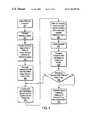
- FIG. 4is a flowchart illustrating the steps in a process for detecting a three way calling event in accordance with a preferred embodiment of the present invention
- FIG. 5is a block diagram of the internal components of a three way call detection system designed in accordance with the present invention.
- FIG. 6illustrates an auto correlator used to detect echoed versions of a pseudo random sequence in a preferred embodiment of the present invention.
- the present inventionis method or process, an apparatus, and a computer readable software product which is preferably implemented within a local telephone system and is utilized in order to detect a three way call event whenever the local telephone system is in use.
- the method or processmay be implemented through software, firmware and/or hardware having any number of modules which cause a processor to perform the various steps of the process or method.
- the present inventiondetects an off-hook condition once a telephone connection has been completed between the local telephone system and a remote telephone (i.e., once the called party lifts the receiver of the remote telephone). Once the off-hook condition is detected, the present invention transmits an initial reference signal over the two way connection in order to determine the initial characteristics of the two way connection.
- the present inventionuses a pseudo-random, PN, noise source to generate a PN noise sequence which is used as the reference signal.
- the present inventionconverts the PN noise sequence into a spread spectrum signal and transmits the spread spectrum signal over the established two way connection.
- the PN noise sequenceis reflected or echoed back at various impedance mismatch points in the network, such as a dual hybrid circuit at the remote telephone.
- the present inventionsamples incoming signals at the local telephone and is able to accurately detect each echoed version of the PN noise sequence, including a far end echo from the dual hybrid circuit of the remote telephone.
- the present inventiongenerates an initial echo profile showing each echo detected over a period of time and its associated delay time. This initial echo profile is stored in a memory.
- the processis then continually repeated throughout the duration of the telephone call.
- the reference signalis generated and transmitted, and the incoming signal line at the local telephone is sampled for echoed versions of the reference signal.
- Each echo detected, and its associated delay timeis compared with the echoes recorded in the initial echo profile which is stored in memory. Significant changes in the number and timing of detected echoes are used to indicate a three way calling event.
- the reference signalmay be any type of accurately detectable signal; however, in using a PN noise sequence and auto correlation techniques in a preferred embodiment, the system and method of the present invention has a further advantage of high processing gain, a feature which allows a returning echo to be detected in poor signal to noise ratio environments or very low echo environments.
- the present inventionmay use an FM “Chirp” signal as the reference signal instead of a pseudo random noise sequence.
- FIG. 1there is shown a block diagram of a conventional long distance telephone circuit for illustrating the concept of echoes.
- the telephone circuitincludes remote and local telephones 116 , 112 , dual hybrid circuits 120 , 122 , and balancing networks 202 , 204 .
- the dual hybrid circuits 120 and 122connect single wire pairs 111 and 113 to two sets of wires, with each set of wire used for transmitting signals in the alternate direction.
- the telephone audio signalsare transmitted from local telephone 112 through dual hybrid circuit 122 and over one set of wires to remote telephone 116 ; while telephone audio signals are transmitted from remote telephone 116 through dual hybrid circuit 120 and over the other set of wires to local telephone 112 .
- the balancing networks 202 and 204are designed to match impedances between the single wire pairs 111 and 113 and the dual hybrid circuits 120 , 122 such that the circuits will appear to be “invisible” on the line. If the balancing networks 202 , 204 are unable to closely match the impedances, then echoes occur on the lines. More specifically, whenever a telephone audio signal encounters an impedance mismatch in the telephone circuit, a portion of that signal is reflected (i.e., returned) as a reflection echo. In FIG. 1, impedance mismatch occurs at dual hybrid circuits 120 , 122 , thereby giving rise to reflection echoes E 1 and E 2 , respectively.
- reflection echo E 1is an echo of the signal orginally transmitted from local telephone 112 to remote telephone 116 and reflection echo E 2 is an echo of the signal originally transmitted from remote telephone 116 to local telephone 112 .
- Reflection echoesare best described by further examining the function of dual hybrid circuits 120 , 122 .
- dual hybrid circuits 120 , 122are used to couple single wire pairs 111 and 113 to two different dual wire sets in the long-distance telephone circuit.
- a typical dual hybrid circuitcomprises a bridge circuit having three ports. Two of the ports are for receiving and transmitting audio signals, respectively, and the third port is coupled to one of the balancing networks 202 or 204 in order to prevent impedance mismatch between the single wire pair and the two different dual wire sets. If the bridge circuit is not perfectly balanced by the balancing network 202 , 204 then the receiving port can be coupled to the transmitting port, thereby giving rise to a reflection echo.
- a telephone call that is connected normallyexhibits a relatively constant set of echo characteristics (e.g., relatively constant impedance matching characteristics).
- a relatively constant set of echo characteristicse.g., relatively constant impedance matching characteristics.
- impedance mismatch points on the linechanges, for example, by being put on hold at the central office during a three way call event, a changed set of impedance matching characteristics are exhibited. This change in impedance matching characteristics causes reflection echoes to be generated at different points in the telephone circuit.
- FIG. 2illustrates a functional block diagram of a telephone system 200 which includes a three way call detection system 201 in accordance with the present invention.
- telephone system 200comprises a remote telephone 216 , a central office 210 , a local telephone 212 , dual hybrid circuits 220 and 222 , and a three way call detection system 201 in accordance with the present invention.
- local telephone 212is coupled to the central office 210 through dual hybrid circuit 220 .
- the dual hybrid circuit 220converts a single wire pair from the local telephone 212 into a dual pair of wires.
- Each wire pair in the dual pair of wiresis preferably a copper wire pair used to transmit audio signals in opposite directions—i.e. one copper wire pair in the dual pair of wires is for transmitting signals in a first direction toward the local telephone 212 , and the other copper wire pair is used for transmitting signals in a second direction from local telephone 212 to the central office 210 .
- Dual hybrid circuit 222is used to couple the remote telephone 216 to the central office 210 .
- the dual hybrid circuit 222converts a single wire pair from remote telephone 216 into a dual pair of wires which transmit telephone voice signals in opposite directions through the central office 210 , to and from remote telephone 216 .
- Each wire pair in the dual pair of wiresis preferably a copper wire pair used to transmit audio signals in the opposite direction—i.e. one copper wire pair in the dual pair of wires is for transmitting signals in a first direction from the remote telephone 216 , and the other copper wire pair is used for transmitting signals in a second direction to the remote telephone 216 .
- central office 210contains a main switchboard or patch panel 225 for routing the telephone voice signals between local telephone 212 and remote telephone 216 .
- the central office 210may also include multiple amplifiers and filters (not shown) for amplifying and filtering each telephone call as it is routed through the central office 210 .
- the three way call detection system 201 of the present inventionis coupled to the single wire pair at the local telephone 212 end.
- local telephone 212 , dual hybrid circuit 220 and the three way call detection system 201are all implemented as part of a private telephone system.
- FIG. 2further shows a third party telephone 250 coupled to the central office 210 through dual hybrid circuit 242 .
- Dual hybrid circuit 242converts a single wire pair from third party telephone 250 into a dual pair of wires. Each wire pair in the dual pair of wires transmits signals in the opposite direction—i.e. one wire pair transmits signals in a first direction toward the third party telephone 250 and the other wire pair transmits signals in a second direction from the third party telephone 250 .
- signalsare routed from the local telephone 212 , through the main switchboard 225 in the central office 210 , to the third party telephone 250 .
- the three way call detection system 201 of the present inventionfirst detects an off-hook condition using techniques known in the art—i.e. the invention first detects when the remote telephone 216 is off hook or picked up, thereby indicating a two-way telephone connection has being established between the local telephone 212 and remote telephone 216 .
- the three way call detection system 201 of the present inventioninjects a reference signal into the voice signals being transmitted from the local telephone 212 on the outgoing line in the single wire pair between the local telephone 212 and the dual hybrid circuit 220 .
- the reference signalis a pseudo-random noise sequence which has been converted into a wide band, low spectral density spread spectrum signal before it is injected into the voice signals transmitted from local telephone 212 .
- the present inventionmay inject an FM “Chirp” signal into the voice signals transmitted from the local telephone 212 .
- the three way call detection system 201then samples incoming voice signals being transmitted to the local telephone 212 on the incoming line in the single wire pair between the dual hybrid circuit 220 and the local telephone 212 , in order to detect echoed versions of the initial reference signal.
- the present inventionuses an auto-correlation filtering technique in order to accurately detect each reflected echo of the reference signal where the reference signal is a pseudo-random noise sequence.
- the reference signalis an FM “Chirp” signal
- a matched FIR filtering technique with an infinite impulse responsemay be used.
- echoeswill occur wherever there is an impedance mismatch in the line, such as at the dual hybrid circuits 220 and 222 .
- An echo or delay time for each detected echois measured, and the number of echoes and their individual echo or delay times are recorded in an initial echo profile. This initial echo profile establishes the echo characteristics for a normal two way phone connection between local telephone 212 and remote telephone 216 .
- a number of echoeswill occur, including those which occur at dual hybrid circuits 220 and 222 , with each echo having an associated echo or delay time which occurs at regular intervals in time.
- the echo or delay timerepresents the amount of time required for the reference signal to travel from the three way call detection system 201 to the point where the impedance mismatch occurs (i.e., dual hybrid circuits 220 and 222 ) and back to the three way call detection system 201 .
- the present inventionaccurately detects each echoed version of the reference signal and thereafter generates an initial echo profile which shows each echo detected and the point in time where an echoed version of the reference signal was detected relative to the transmit time when the reference signal was first transmitted. Once the initial echo profile has been generated, these echo characteristics can be continuously compared to subsequent information obtained over the duration of the phone call in order to determine whether a three way calling event has occurred.
- the three way call detection system 201continues to inject the reference signal into the voice signals being transmitted from the local telephone 212 .
- the reference signalis a wide band spread spectrum pseudo-random noise sequence.
- the reference signalmay be an FM “Chirp” signal.
- each time the reference signal is injectedthe signal is muted from the local telephone 212 so it will not be heard at the local telephone.
- the reference signalis continuously injected at regular intervals over the duration of the telephone call.
- the three way call detection system 201further continues to sample the incoming voice signals in order to detect incoming echoed versions of the reference signal.
- the reference signalis transmitted in at least four bursts during a single interval. This way multiple echoes can be detected at regular intervals when the incoming voice signals are sampled.
- the detected echoed versions of the reference signalare compared with the echoes recorded in the initial echo profile.
- the initial echo profileshows the number of echoes initially detected and the location in time (i.e.—when) each of the echoed versions were detected when the two way call between the local telephone 212 and the remote telephone 216 was first established. If new echoes are subsequently detected over the duration of the phone call and these new echoes remain consistent—i.e. they appear consistently over the four bursts, then a change in the echo characteristics of the line or connection has been detected thereby signaling the occurrence of a three way calling event.
- FIG. 3 aillustrates a sample histogram which is used in accordance with the present invention.
- the histogramshows a time interval T on the horizontal axis and a number of echoes X on the vertical axis. The number X is incremented as each echo is detected at the appropriate time when the echo is detected over the time interval T.
- the histogramshows that 5 echoes have been detected at a time T 1 , 10 echoes have been detected at a time T 2 , and 2 echoes have been detected at a time T 3 over the course of a regular time interval T during which the incoming line to the local telephone is sampled relative to the transmission of each reference signal.
- the histogramcompares the number and timing of each echo detected with the number and timing of the echoes recorded in an initial echo profile. If a significant number of echoes are detected at any point in time which differs from the information in the initial echo profile, the system alerts that a possible third connection has been made on the line, thereby indicating the detection of a three way calling event.
- FIG. 3 bshows a sample initial echo profile which indicates that echoes Ech 1 , Ech 2 , and Ech 3 were detected at times T 1 , T 2 and T 4 when the initial echo profile was created.
- the histogramshows that over the duration of the time interval T, 5 echoes have subsequently been detected at time T 1 , relative to each transmission of the reference signal.
- the histogramshows that 10 echoes have subsequently been detected at time T 2 , relative to the transmission of the reference signal over the duration of the time interval T.
- 10 echoeshave been detected we can be pretty sure these echoes are definitely echoed versions of the reference signal and not some type of anomaly.
- these echoeshave all occurred at the point in time T 2 , which corresponds with the same point in time T 2 where the echoes Ech 2 were recorded in the initial echo profile, we can be pretty sure that at least in so far as these echoes are concerned there has been no change in the echo characteristics of the line up to the point where these echoes occurred.
- the histogramshows that 2 echoes have been detected at a time T 3
- the initial echo profile as shown in FIG. 3 bshows echoes Ech 3 were originally detected at time T 4 . Since only 2 echoes have been detected at this time T 3 , this may be an anomaly; however, if the system detects several more echoes, above some threshold number, with each of these echoes occurring at the time T 3 , instead of the time T 4 as indicated by the initial echo profile, a three way calling event may have occurred, altering the echo characteristics of the line and the present invention generates a signal alerting an operator to this fact.
- the voice signals from local telephone 212are now also routed through dual hybrid circuit 242 to the 3 rd party telephone 250 . Additional echoes will result as the reference signal is reflected at the impedance mismatch of the dual hybrid circuit 242 . Moreover, the additional time required to route the reference signal through the central office 210 to the third party telephone 250 and back, significantly increases the echo delay time associated with these additional echoes, thereby ensuring the likelihood that they will not overlap with any of the other echoes previously detected and recorded in the initial echo profile.
- these additional echoeswill be detected at a different point in time from those echoes which were originally detected in the initial profile. If these additional echoes are detected several times as the process continues and the histogram shows a significant change in the echo profile over time, i.e. if the number of echoes detected at this point in time exceeds a threshold value, the system triggers the detection of a three way calling event and alerts an operator.
- FIG. 4illustrates a flowchart showing the steps in a process for detecting three way calling events in accordance with the present invention.
- the first step 401 in the processis to detect an off hook condition signaling that a two way connection has been made whenever a call is made from the local telephone 212 .
- the next step in the process 402is to transmit a reference signal on the outgoing signal line from the local telephone.
- the third step 403 in the processis to monitor the incoming signal line at the local telephone in order to detect echoed versions of the reference signal. As each echo is detected, its associated echo delay time is measured.
- the number of echoes detected and each of their associated delay timesare then recorded in an initial echo profile.
- the reference signalis continuously injected into the voice signals transmitted from the local telephone over the outgoing line (step 405 ).
- the incoming lineis monitored and echoed versions of the reference signal are detected (step 406 ).
- a histogramis created in a memory showing each detected echo and the associated echo delay time (step 407 ).
- the histogramis continuously compared with information in the initial echo profile (step 408 ). If the histogram shows that an echo has been continuously detected for a number of times exceeding a predetermined threshold and the delay time associated with that echo does not correlate with any of the echoes detected and recorded in the initial echo profile (step 409 ), a signal is generated indicating the possible occurrence of a three way calling event (step 410 ).
- FIG. 5illustrates a functional block diagram showing the internal components of one preferred embodiment of a three way call detection system 201 of the present invention.
- the three way call detection systemincludes a transmitting unit 510 having a pseudo random sequence generator 515 , a software module 520 , a static memory array 525 and a transmit logic module with D/A converter 530 .
- the three way call detection systemfurther includes a receiving unit 550 coupled to the transmitting unit and having an A/D converter 555 , a correlator 565 , a sample count register 570 and a comparing module 575 .
- the operations of the transmitting unit 510 and the receiving unit 550shall now be described in further detail.
- the software module 520 in the transmitting unit 510instructs the pseudo random sequence generator 515 to generate a pseudo random sequence which operates as a reference signal.
- This pseudo random sequencewill preferably be between 32 and 256 bits in length, although it is understood that the pseudo random sequence may be longer or shorter as required by the system (with longer sequences requiring more time to detect their echo but ensuring more accurate detection of an echo).
- Each bit in the pseudo random sequenceis preferable represented as a logic high (+1) or a logic low ( ⁇ 1).
- the reference signalis stored in the static memory array 525 for future reference.
- the software module 520also sets the transmit logic module with D/A converter 530 to a preselected transmit audio level.
- the software module 520places the transmitting unit 510 into an idle state. In this state, the transmitting unit 510 is ready and waiting to inject the pseudo random noise sequence into the normal telephone conversation audio streams from the local telephone 212 for transmission to the remote telephone 216 .
- the systemdetects a pick up at the other end of the line at the remote telephone 216 .
- the software module 520places the transmitting unit 510 into a transmit mode such that a copy of the reference signal which is stored in the static memory array 525 is transferred to the transmit logic module with D/A converter 530 where it is converted into a spread spectrum analog signal having the pre-selected audio level, thereby creating a spread spectrum analog signal output.
- This spread spectrum analog signal outputis then injected into and summed with the telephonic voice signals transmitted from the local telephone 212 to the remote telephone 216 .
- the signalis muted at the local telephone 212 so the near end user cannot detect the injection of the spread spectrum signal.
- the software module 520then places the transmitting unit 510 into a hold state.
- the transmitting unit 510waits until the next reference signal is to be transmitted.
- the transmitting unit 510remains in this state until the receiving unit 550 signals that the maximum number of samples, as described further hereinafter, has been reached; in which case the entire process is then repeated at regular intervals over the duration of the telephone call.
- the receiving unit 550While the transmitting unit 510 is in a hold state, the receiving unit 550 will monitor the incoming signals to detect any echoed versions of the reference signal. An initial echo profile will be recorded which includes the number and timing of each detected echo. This profile will also be stored in the static memory array 525 . This initial echo profile contains echo characteristics of the two way connection between the local telephone 212 and remote telephone 216 .
- this process of transmitting the reference signal into the audio stream from local telephone 212is repeated by the transmitting unit 510 intermittently over the duration of the telephone call.
- the receiving unit 510is coupled to the transmitting unit 550 .
- the receiving unit 550monitors the status of the transmitting unit 510 in order to determine when to begin sampling for the returned echoed versions of the pseudo random sequence. Whenever the transmitting unit 510 is in the transmit state or the hold state, the receiving unit 550 is actively sampling the incoming line to local telephone 212 in order to detect any echoed versions of the pseudo random sequence.
- the A/D converter 555 of the receiving unitconverts the incoming telephone audio signals into digital signals having logic high bits (+1) and logic low bits ( ⁇ 1).
- the A/D converter 555then passes the converted digital signals into the correlator 565 .
- the correlator 565acts as a matched filter in order to detect the echoed version of the transmitted pseudo random noise signal.
- the correlator 565is similar to a FIFO register where data is fed in through a first end and out a second end.
- the correlatorreads the information stored in the static memory array (i.e. the original reference signal which was transmitted) and performs a bit by bit comparison between the reference signal with the incoming data as it is passed through the correlator in order to accurately detect the presence of an echoed version of the pseudo random sequence.
- the sample count register 570keeps track of the number of samples taken and the time each sample is taken. Each time the correlator 565 detects an echoed version of the pseudo random sequence, the sample count and time is recorded and stored in a histogram which is generated by the sample count register 570 . Echoed versions are continuously sampled and recorded in the histogram showing the number of echoes detected and echo or delay time of each detected echo.
- the contents of the histogramare then compared with the contents of the echo profile by the comparing module 575 after each sampling period, in order to determine whether a three way calling event has occurred.
- the sample count and time recorded for each of the detected echoed versions of reference signalshould remain constant and should match the information stored in the initial profile.
- the sample count and timing for detected echoes versionswill change significantly from the information stored in the initial profile (i.e., echoes will be detected at different delay times) and the comparing module 575 will detect this difference and alert an operator that a three way calling event has been detected.
- FIG. 6shows a functional block diagram of a preferred embodiment of a special correlator 565 which is used in the three way call detection system of the present invention when the reference signal is a spread spectrum PN sequence.
- the converted incoming digital datais fed through a receive FIFO shift register 601 which is equal in length to the number of bits in the pseudo random sequence—i.e. this shift register 601 is capable of holding the same number of bits positions as that in the pseudo random sequence.
- the receive shift register 601excepts the latest incoming digital data at one end from the A/D converter 555 and shifts the digital data out from the other end.
- the receive shift register 601may also be implemented as a circular buffer with the oldest data being written over with the newest data and a circular rotating pointer used instead of actually shifting the information through a register.
- the receive shift register 601As the digital data is shifted through the receive shift register 601 it is compared with the reference signal stored in the static memory array 525 on a bit by bit basis such that each bit in the reference signal is compared with a corresponding bit in the same position in the shift register 601 using an inverted exclusive—or array (NXOR) 605 a - 605 n .
- NXORexclusive—or array
- the output from each element in the NXOR array 605 a - 605 nis summed with the other outputs at a summing junction 610 .
- the reference signalis a pseudo random noise sequence, any sequence of digital data which passes through the shift register 601 other than the reference signal has the tendency to sum to a low value and therefore, the output of the correlator 565 should remain very low.
- each sampleadds to the filter such that a high level output occurs at the summing junction 610 .
- the output from the summing junctionfalls above a predetermined threshold, an echoed version is said to have been detected and the point in time where it has been detected is recorded in the histogram by the sample count register 570 .
- the results output from the correlator 565are constantly stored in a histogram in the sample count register 570 along with the sampling time or count where those echoes occurred.
- the results stored in the histogram in the sample count register 570are compared with the initial echo profile.
- the sampling times or counts where the correlator 565 output was the highesti.e. the points in time where echoed versions of the reference signal were detected, should remain the same within a given tolerance and given repetition factor when compared with the contents of the initial profile. Accordingly, consistent echoes should be detected with the time between each detection being fairly constant. These echoes should match with the results of the information stored in the initial echo profile—i.e. the number of echoes detected and the timing delay associated with each echo should correlate with the initial echoes detected and stored in the initial profile.
- the sampling times or counts where the output from the correlator 565 is highestdo not match with the information stored in the initial echo profile—i.e if multiple echoes are detected at different periods of time (i.e. one echo from the remote telephone 216 and another echo from the third party telephone 250 ) then this is tracked by the histogram. If this difference continues to occur over a period of time, i.e. if a number of echoes above a threshold value continue to be detected at a point in time different from those recorded in the initial profile, then a three way calling event has been detected.
- the comparing module 575will preferably send an alarm signal to an operator alerting the operator that a three way calling event has been detected.
- This alarm signalmay be an audio alarm signal or a visual alarm signal such a lighted LED indicating the detection of a three way calling event.
Landscapes
- Engineering & Computer Science (AREA)
- Signal Processing (AREA)
- Multimedia (AREA)
- Cable Transmission Systems, Equalization Of Radio And Reduction Of Echo (AREA)
Abstract
Description
Claims (27)
Priority Applications (1)
| Application Number | Priority Date | Filing Date | Title |
|---|---|---|---|
| US09/435,013US6763099B1 (en) | 1999-11-05 | 1999-11-05 | Advanced three way call detection system and method using spread spectrum techniques |
Applications Claiming Priority (1)
| Application Number | Priority Date | Filing Date | Title |
|---|---|---|---|
| US09/435,013US6763099B1 (en) | 1999-11-05 | 1999-11-05 | Advanced three way call detection system and method using spread spectrum techniques |
Publications (1)
| Publication Number | Publication Date |
|---|---|
| US6763099B1true US6763099B1 (en) | 2004-07-13 |
Family
ID=32682140
Family Applications (1)
| Application Number | Title | Priority Date | Filing Date |
|---|---|---|---|
| US09/435,013Expired - LifetimeUS6763099B1 (en) | 1999-11-05 | 1999-11-05 | Advanced three way call detection system and method using spread spectrum techniques |
Country Status (1)
| Country | Link |
|---|---|
| US (1) | US6763099B1 (en) |
Cited By (30)
| Publication number | Priority date | Publication date | Assignee | Title |
|---|---|---|---|---|
| US20030091181A1 (en)* | 2001-11-13 | 2003-05-15 | Thomas Martin | 3-Way call detection system and method |
| US20030231705A1 (en)* | 2002-03-12 | 2003-12-18 | Kabushiki Kaisha Toshiba | Digital correlators |
| US20050014491A1 (en)* | 1997-03-27 | 2005-01-20 | T-Netix, Inc. | Method and apparatus for detecting a secondary destination of a telephone call based on changes in the telephone signal path |
| US20050259809A1 (en)* | 2004-05-21 | 2005-11-24 | Hodge Stephen L | Means and method for detecting three-way call attempts |
| US20070206761A1 (en)* | 2004-10-12 | 2007-09-06 | Anders Joseph C | Comparative tone return time three-way call detect |
| US20070269033A1 (en)* | 2003-08-05 | 2007-11-22 | Martin Thomas J | Three-way call detection using steganography |
| US7380035B1 (en)* | 2005-03-24 | 2008-05-27 | Xilinx, Inc. | Soft injection rate control for buses or network-on-chip with TDMA capability |
| US20080198978A1 (en)* | 2007-02-15 | 2008-08-21 | Olligschlaeger Andreas M | System and method for three-way call detection |
| US20080273684A1 (en)* | 2007-05-04 | 2008-11-06 | 3V Technologies Incorporated | Systems and Methods for RFID-Based Access Management of Electronic Devices |
| US20090168672A1 (en)* | 2007-12-28 | 2009-07-02 | Ehud Shoor | Methods and appratus for signal echo cancellation and transmitter calibration in full duplex systems |
| US20090190575A1 (en)* | 2007-12-11 | 2009-07-30 | Fujitsu Limited | Packet capturing apparatus, packet capturing method and packet capturing program |
| US20100202595A1 (en)* | 2009-02-12 | 2010-08-12 | Value-Added Communictions, Inc. | System and method for detecting three-way call circumvention attempts |
| US7881446B1 (en) | 2004-09-03 | 2011-02-01 | Confinement Telephony Technology, Llc | Telephony system and method with enhanced validation |
| US7961860B1 (en) | 2006-11-22 | 2011-06-14 | Securus Technologies, Inc. | Systems and methods for graphically displaying and analyzing call treatment operations |
| US8731934B2 (en) | 2007-02-15 | 2014-05-20 | Dsi-Iti, Llc | System and method for multi-modal audio mining of telephone conversations |
| EP2736237A1 (en)* | 2012-11-26 | 2014-05-28 | PBXwall Limited | Telecommunication fraud prevention system and method |
| US8917848B2 (en) | 2013-03-15 | 2014-12-23 | Telmate, Llc | Call management for secure facilities |
| US9225838B2 (en) | 2009-02-12 | 2015-12-29 | Value-Added Communications, Inc. | System and method for detecting three-way call circumvention attempts |
| US9674350B2 (en) | 2015-04-27 | 2017-06-06 | Pbxwall Ltd. | Telecommunication fraud prevention system and method |
| US20170318143A1 (en)* | 2016-04-27 | 2017-11-02 | Global Tel*Link Corp. | Monitoring and preventing communications between inmates |
| US9912803B1 (en)* | 2017-05-25 | 2018-03-06 | I.M.N.A Solutions Ltd | Recording detection during a communication session |
| US9923936B2 (en) | 2016-04-07 | 2018-03-20 | Global Tel*Link Corporation | System and method for third party monitoring of voice and video calls |
| US9930088B1 (en) | 2017-06-22 | 2018-03-27 | Global Tel*Link Corporation | Utilizing VoIP codec negotiation during a controlled environment call |
| US10027797B1 (en) | 2017-05-10 | 2018-07-17 | Global Tel*Link Corporation | Alarm control for inmate call monitoring |
| US10074362B2 (en) | 2017-01-31 | 2018-09-11 | Global Tel*Link Corporation | System and method for assessing security threats and criminal proclivities |
| US10129392B1 (en) | 2017-08-25 | 2018-11-13 | Global Tel*Link Corporation | Systems and methods for detecting inmate to inmate conference calls |
| US10225396B2 (en) | 2017-05-18 | 2019-03-05 | Global Tel*Link Corporation | Third party monitoring of a activity within a monitoring platform |
| US10330769B1 (en)* | 2016-06-06 | 2019-06-25 | The Boeing Company | Method and apparatus for geolocating emitters in a multi-emitter environment |
| US10572961B2 (en) | 2016-03-15 | 2020-02-25 | Global Tel*Link Corporation | Detection and prevention of inmate to inmate message relay |
| US10860786B2 (en) | 2017-06-01 | 2020-12-08 | Global Tel*Link Corporation | System and method for analyzing and investigating communication data from a controlled environment |
Citations (77)
| Publication number | Priority date | Publication date | Assignee | Title |
|---|---|---|---|---|
| US3851121A (en) | 1973-12-10 | 1974-11-26 | Gen Telephone Co Of California | Automatic remote service monitoring system |
| US4001513A (en) | 1975-07-31 | 1977-01-04 | Northern Electric Company Limited | Method and apparatus for the detection of fraudulent toll telephone calls |
| US4002848A (en) | 1974-11-14 | 1977-01-11 | Reliable Electric Company | Toll fraud eliminator for telephone systems |
| US4188508A (en) | 1978-08-21 | 1980-02-12 | Brindle Patrick A | Telephone call restricting apparatus |
| US4310726A (en) | 1980-02-04 | 1982-01-12 | Bell Telephone Laboratories, Incorporated | Method of identifying a calling station at a call terminating facility |
| US4518825A (en) | 1983-10-11 | 1985-05-21 | Telecalc, Inc. | Telephone interconnect detection system |
| US4559416A (en) | 1983-10-12 | 1985-12-17 | Morgan Industries, Inc. | Telephone line activity monitor |
| US4602129A (en) | 1979-11-26 | 1986-07-22 | Vmx, Inc. | Electronic audio communications system with versatile message delivery |
| US4696031A (en) | 1985-12-31 | 1987-09-22 | Wang Laboratories, Inc. | Signal detection and discrimination using waveform peak factor |
| US4726057A (en) | 1986-07-28 | 1988-02-16 | AT&T Information Systems Inc. American Telephone & Telegraph Company | Answer detection method and apparatus for coin telephone sets |
| US4799255A (en) | 1987-01-30 | 1989-01-17 | American Telephone And Telegraph Company - At&T Information Systems | Communication facilities access control arrangement |
| US4815120A (en) | 1987-07-28 | 1989-03-21 | Enforcement Support Incorporated | Computerized telephone monitoring system |
| US4885765A (en) | 1986-10-15 | 1989-12-05 | Kabushiki Kaisha Toshiba | Telephone system with stimulus operation or default operation |
| US4896348A (en) | 1988-07-01 | 1990-01-23 | Palco Telecom Inc. | Paystation monitor circuit to prevent fraudulent use |
| US4899375A (en) | 1988-09-23 | 1990-02-06 | American Telephone & Telegraph Company, At&T Bell Laboratories | More efficient call handling for operator assistance calls |
| US4901341A (en) | 1988-06-22 | 1990-02-13 | Messager Partners | Method and apparatus for caller-controlled receipt and delivery of voice messages |
| US4922520A (en) | 1986-12-31 | 1990-05-01 | M. A. Kempner, Inc. | Automatic telephone polling system |
| US4922519A (en) | 1986-05-07 | 1990-05-01 | American Telephone And Telegraph Company | Automated operator assistance calls with voice processing |
| US4924488A (en) | 1987-07-28 | 1990-05-08 | Enforcement Support Incorporated | Multiline computerized telephone monitoring system |
| US4933967A (en) | 1989-06-01 | 1990-06-12 | At&T Company | Automatically-effected move of a subscriber between electronic message service systems in a network |
| US4933966A (en) | 1989-01-23 | 1990-06-12 | Intellicall, Inc. | Method and apparatus for performing an automated collect call |
| US4935956A (en) | 1988-05-02 | 1990-06-19 | Telequip Ventures, Inc. | Automated public phone control for charge and collect billing |
| US4937862A (en) | 1988-10-14 | 1990-06-26 | Enforcement Support Incorporated | Remote monitoring device |
| US4993068A (en) | 1989-11-27 | 1991-02-12 | Motorola, Inc. | Unforgeable personal identification system |
| US5023869A (en) | 1989-03-27 | 1991-06-11 | Alberta Telecommunications Research Centre | Method and apparatus for maximizing the transmission capacity of a multi-channel bidirectional communications link |
| US5023906A (en) | 1990-04-24 | 1991-06-11 | The Telephone Connection | Method for monitoring telephone call progress |
| US5033088A (en) | 1988-06-06 | 1991-07-16 | Voice Processing Corp. | Method and apparatus for effectively receiving voice input to a voice recognition system |
| US5054059A (en) | 1989-10-24 | 1991-10-01 | Stern Telecommunications Corp. | Telephone dialing system for specialized services |
| US5063593A (en) | 1989-08-23 | 1991-11-05 | Samsung Electronics Co., Ltd. | Tone-type recognition method |
| US5109405A (en) | 1988-07-11 | 1992-04-28 | Dytel Corporation | Automated call screening |
| US5131024A (en) | 1990-05-16 | 1992-07-14 | Messager Partners | Method and apparatus for providing proactive call services following call completion |
| US5150357A (en) | 1989-06-12 | 1992-09-22 | Emil Hopner | Integrated communications system |
| US5163083A (en) | 1990-10-12 | 1992-11-10 | At&T Bell Laboratories | Automation of telephone operator assistance calls |
| JPH0530193A (en) | 1991-07-19 | 1993-02-05 | Nec Corp | Malcious call restriction connection system |
| US5187740A (en) | 1991-10-01 | 1993-02-16 | Mci Communications Corporation | Method and apparatus for telephone call reorigination |
| US5200995A (en) | 1990-12-24 | 1993-04-06 | Gaukel John J | Universal outgoing call restriction circuit |
| US5222120A (en) | 1990-04-23 | 1993-06-22 | Mci Communications Corporation | Long distance telephone switching system with enhanced subscriber services |
| US5229764A (en) | 1991-06-20 | 1993-07-20 | Matchett Noel D | Continuous biometric authentication matrix |
| US5276731A (en) | 1991-04-26 | 1994-01-04 | Rolm Company | Method and apparatus for handling incoming telephone calls |
| US5305312A (en) | 1992-02-07 | 1994-04-19 | At&T Bell Laboratories | Apparatus for interfacing analog telephones and digital data terminals to an ISDN line |
| US5309505A (en) | 1991-05-20 | 1994-05-03 | Inventions, Inc. | Automated voice system for improving agent efficiency and improving service to parties on hold |
| US5311589A (en) | 1992-03-31 | 1994-05-10 | At&T Bell Laboratories | Apparatus and method for audible signaling tone recognition |
| US5319702A (en) | 1992-07-29 | 1994-06-07 | Tele-Matic Corporation | Method and apparatus for detecting and responding to hook flash events occurring on a remote telephone |
| US5325427A (en) | 1992-03-23 | 1994-06-28 | At&T Bell Laboratories | Apparatus and robust method for detecting tones |
| US5327489A (en) | 1991-12-16 | 1994-07-05 | At&T Bell Laboratories | Method and apparatus for monitoring a network for customer signaling during the term of a call |
| US5329578A (en) | 1992-05-26 | 1994-07-12 | Northern Telecom Limited | Personal communication service with mobility manager |
| US5345595A (en) | 1992-11-12 | 1994-09-06 | Coral Systems, Inc. | Apparatus and method for detecting fraudulent telecommunication activity |
| US5351287A (en) | 1992-12-11 | 1994-09-27 | Bell Communications Research, Inc. | Method and apparatus for data evidence collection |
| US5355403A (en) | 1990-10-01 | 1994-10-11 | United States Advance Network, Inc. | Customized, billing-controlled call bridging system |
| US5375161A (en) | 1984-09-14 | 1994-12-20 | Accessline Technologies, Inc. | Telephone control system with branch routing |
| US5442696A (en) | 1991-12-31 | 1995-08-15 | At&T Corp. | Method and apparatus for detecting control signals |
| US5452347A (en) | 1993-01-07 | 1995-09-19 | Rolm Company | Dual-line telephone bridging device that gives remote telephones access to communications features |
| US5465293A (en) | 1993-12-30 | 1995-11-07 | At&T Corp. | Apparatus and method for screening foreign incollect calls to domestic non-collect call telephone numbers to reduce fraud |
| US5471519A (en) | 1993-02-26 | 1995-11-28 | Bellsouth Corporation | Communications monitoring and control system |
| US5483593A (en) | 1990-12-21 | 1996-01-09 | Motorola, Inc. | Call progress decoder for multiple cadenced tones on telephone lines |
| US5483582A (en) | 1991-12-12 | 1996-01-09 | Messager Partners | Applications platform for a telephone system gateway interface |
| US5535261A (en) | 1993-08-20 | 1996-07-09 | Gateway Technologies, Inc. | Selectively activated integrated real-time recording of telephone conversations |
| US5539812A (en) | 1992-07-29 | 1996-07-23 | Kitchin; Dwight W. | Method and apparatus for detecting an attempted three-way conference call on a remote telephone |
| US5566229A (en) | 1992-08-24 | 1996-10-15 | At&T | Voice directed communications system employing shared subscriber identifiers |
| US5583934A (en) | 1995-03-03 | 1996-12-10 | Advanced Micro Devices, Inc. | DC level control for an electronic telephone line card |
| US5606604A (en) | 1993-12-13 | 1997-02-25 | Lucent Technologies Inc. | System and method for preventing fraud upon PBX through a remote maintenance or administration port |
| US5617471A (en) | 1995-05-25 | 1997-04-01 | Rogers; Wesley D. | Telecommunications system for transferring a telephone call |
| US5627887A (en) | 1994-10-18 | 1997-05-06 | At&T | Method for processing collect calls |
| US5651056A (en) | 1995-07-13 | 1997-07-22 | Eting; Leon | Apparatus and methods for conveying telephone numbers and other information via communication devices |
| US5724404A (en) | 1995-07-03 | 1998-03-03 | Garcia; Max | Integrated international telephone circuit monitoring system |
| US5722418A (en) | 1993-08-30 | 1998-03-03 | Bro; L. William | Method for mediating social and behavioral processes in medicine and business through an interactive telecommunications guidance system |
| US5745553A (en) | 1996-04-16 | 1998-04-28 | At&T Corp. | On-demand communications services |
| US5796811A (en) | 1995-11-15 | 1998-08-18 | Gateway Technologies, Inc. | Three way call detection |
| US5799068A (en) | 1992-06-29 | 1998-08-25 | Elonex I.P. Holdings Ltd. | Smart phone integration with computer systems |
| US5805685A (en) | 1995-11-15 | 1998-09-08 | Gateway Technologies, Inc. | Three way call detection by counting signal characteristics |
| US5809125A (en) | 1992-07-09 | 1998-09-15 | Gammino; John R. | Method and apparatus for intercepting potentially fraudulent telephone calls |
| US5859907A (en)* | 1994-05-06 | 1999-01-12 | Ntt Mobile Communications Network, Inc. | Echo canceler and echo path estimating method |
| US5883945A (en) | 1995-10-27 | 1999-03-16 | United States Advanced Network, Inc. | Three-way call detection and response system |
| US5960064A (en) | 1994-06-23 | 1999-09-28 | At&T Corp | Call screening method and apparatus for use in completing telephone calls |
| US6052454A (en) | 1996-01-16 | 2000-04-18 | Global Tel*Link Corp. | Telephone apparatus with recording of phone conversations on massive storage |
| US6141406A (en)* | 1997-03-27 | 2000-10-31 | T-Netix, Inc. | Method and apparatus for detecting a secondary destination of a telephone call based on changes in the telephone signal path |
| US6188751B1 (en) | 1996-04-17 | 2001-02-13 | Convergys Cmg Utah Inc. | Call processing system with call screening |
- 1999
- 1999-11-05USUS09/435,013patent/US6763099B1/ennot_activeExpired - Lifetime
Patent Citations (78)
| Publication number | Priority date | Publication date | Assignee | Title |
|---|---|---|---|---|
| US3851121A (en) | 1973-12-10 | 1974-11-26 | Gen Telephone Co Of California | Automatic remote service monitoring system |
| US4002848A (en) | 1974-11-14 | 1977-01-11 | Reliable Electric Company | Toll fraud eliminator for telephone systems |
| US4001513A (en) | 1975-07-31 | 1977-01-04 | Northern Electric Company Limited | Method and apparatus for the detection of fraudulent toll telephone calls |
| US4188508A (en) | 1978-08-21 | 1980-02-12 | Brindle Patrick A | Telephone call restricting apparatus |
| US4602129A (en) | 1979-11-26 | 1986-07-22 | Vmx, Inc. | Electronic audio communications system with versatile message delivery |
| US4310726A (en) | 1980-02-04 | 1982-01-12 | Bell Telephone Laboratories, Incorporated | Method of identifying a calling station at a call terminating facility |
| US4518825A (en) | 1983-10-11 | 1985-05-21 | Telecalc, Inc. | Telephone interconnect detection system |
| US4559416A (en) | 1983-10-12 | 1985-12-17 | Morgan Industries, Inc. | Telephone line activity monitor |
| US5375161A (en) | 1984-09-14 | 1994-12-20 | Accessline Technologies, Inc. | Telephone control system with branch routing |
| US4696031A (en) | 1985-12-31 | 1987-09-22 | Wang Laboratories, Inc. | Signal detection and discrimination using waveform peak factor |
| US4922519A (en) | 1986-05-07 | 1990-05-01 | American Telephone And Telegraph Company | Automated operator assistance calls with voice processing |
| US4726057A (en) | 1986-07-28 | 1988-02-16 | AT&T Information Systems Inc. American Telephone & Telegraph Company | Answer detection method and apparatus for coin telephone sets |
| US4885765A (en) | 1986-10-15 | 1989-12-05 | Kabushiki Kaisha Toshiba | Telephone system with stimulus operation or default operation |
| US4922520A (en) | 1986-12-31 | 1990-05-01 | M. A. Kempner, Inc. | Automatic telephone polling system |
| US4799255A (en) | 1987-01-30 | 1989-01-17 | American Telephone And Telegraph Company - At&T Information Systems | Communication facilities access control arrangement |
| US4924488A (en) | 1987-07-28 | 1990-05-08 | Enforcement Support Incorporated | Multiline computerized telephone monitoring system |
| US4815120A (en) | 1987-07-28 | 1989-03-21 | Enforcement Support Incorporated | Computerized telephone monitoring system |
| US4935956A (en) | 1988-05-02 | 1990-06-19 | Telequip Ventures, Inc. | Automated public phone control for charge and collect billing |
| US5033088A (en) | 1988-06-06 | 1991-07-16 | Voice Processing Corp. | Method and apparatus for effectively receiving voice input to a voice recognition system |
| US4901341A (en) | 1988-06-22 | 1990-02-13 | Messager Partners | Method and apparatus for caller-controlled receipt and delivery of voice messages |
| US4896348A (en) | 1988-07-01 | 1990-01-23 | Palco Telecom Inc. | Paystation monitor circuit to prevent fraudulent use |
| US5109405A (en) | 1988-07-11 | 1992-04-28 | Dytel Corporation | Automated call screening |
| US4899375A (en) | 1988-09-23 | 1990-02-06 | American Telephone & Telegraph Company, At&T Bell Laboratories | More efficient call handling for operator assistance calls |
| US4937862A (en) | 1988-10-14 | 1990-06-26 | Enforcement Support Incorporated | Remote monitoring device |
| US4933966A (en) | 1989-01-23 | 1990-06-12 | Intellicall, Inc. | Method and apparatus for performing an automated collect call |
| US5023869A (en) | 1989-03-27 | 1991-06-11 | Alberta Telecommunications Research Centre | Method and apparatus for maximizing the transmission capacity of a multi-channel bidirectional communications link |
| US4933967A (en) | 1989-06-01 | 1990-06-12 | At&T Company | Automatically-effected move of a subscriber between electronic message service systems in a network |
| US5150357A (en) | 1989-06-12 | 1992-09-22 | Emil Hopner | Integrated communications system |
| US5063593A (en) | 1989-08-23 | 1991-11-05 | Samsung Electronics Co., Ltd. | Tone-type recognition method |
| US5054059A (en) | 1989-10-24 | 1991-10-01 | Stern Telecommunications Corp. | Telephone dialing system for specialized services |
| US4993068A (en) | 1989-11-27 | 1991-02-12 | Motorola, Inc. | Unforgeable personal identification system |
| US5222120A (en) | 1990-04-23 | 1993-06-22 | Mci Communications Corporation | Long distance telephone switching system with enhanced subscriber services |
| US5023906A (en) | 1990-04-24 | 1991-06-11 | The Telephone Connection | Method for monitoring telephone call progress |
| US5131024A (en) | 1990-05-16 | 1992-07-14 | Messager Partners | Method and apparatus for providing proactive call services following call completion |
| US5355403A (en) | 1990-10-01 | 1994-10-11 | United States Advance Network, Inc. | Customized, billing-controlled call bridging system |
| US5163083A (en) | 1990-10-12 | 1992-11-10 | At&T Bell Laboratories | Automation of telephone operator assistance calls |
| US5483593A (en) | 1990-12-21 | 1996-01-09 | Motorola, Inc. | Call progress decoder for multiple cadenced tones on telephone lines |
| US5200995A (en) | 1990-12-24 | 1993-04-06 | Gaukel John J | Universal outgoing call restriction circuit |
| US5276731A (en) | 1991-04-26 | 1994-01-04 | Rolm Company | Method and apparatus for handling incoming telephone calls |
| US5309505A (en) | 1991-05-20 | 1994-05-03 | Inventions, Inc. | Automated voice system for improving agent efficiency and improving service to parties on hold |
| US5229764A (en) | 1991-06-20 | 1993-07-20 | Matchett Noel D | Continuous biometric authentication matrix |
| JPH0530193A (en) | 1991-07-19 | 1993-02-05 | Nec Corp | Malcious call restriction connection system |
| US5187740A (en) | 1991-10-01 | 1993-02-16 | Mci Communications Corporation | Method and apparatus for telephone call reorigination |
| US5483582A (en) | 1991-12-12 | 1996-01-09 | Messager Partners | Applications platform for a telephone system gateway interface |
| US5327489A (en) | 1991-12-16 | 1994-07-05 | At&T Bell Laboratories | Method and apparatus for monitoring a network for customer signaling during the term of a call |
| US5442696A (en) | 1991-12-31 | 1995-08-15 | At&T Corp. | Method and apparatus for detecting control signals |
| US5305312A (en) | 1992-02-07 | 1994-04-19 | At&T Bell Laboratories | Apparatus for interfacing analog telephones and digital data terminals to an ISDN line |
| US5325427A (en) | 1992-03-23 | 1994-06-28 | At&T Bell Laboratories | Apparatus and robust method for detecting tones |
| US5311589A (en) | 1992-03-31 | 1994-05-10 | At&T Bell Laboratories | Apparatus and method for audible signaling tone recognition |
| US5329578A (en) | 1992-05-26 | 1994-07-12 | Northern Telecom Limited | Personal communication service with mobility manager |
| US5799068A (en) | 1992-06-29 | 1998-08-25 | Elonex I.P. Holdings Ltd. | Smart phone integration with computer systems |
| US5809125A (en) | 1992-07-09 | 1998-09-15 | Gammino; John R. | Method and apparatus for intercepting potentially fraudulent telephone calls |
| US5539812A (en) | 1992-07-29 | 1996-07-23 | Kitchin; Dwight W. | Method and apparatus for detecting an attempted three-way conference call on a remote telephone |
| US5319702A (en) | 1992-07-29 | 1994-06-07 | Tele-Matic Corporation | Method and apparatus for detecting and responding to hook flash events occurring on a remote telephone |
| US5566229A (en) | 1992-08-24 | 1996-10-15 | At&T | Voice directed communications system employing shared subscriber identifiers |
| US5345595A (en) | 1992-11-12 | 1994-09-06 | Coral Systems, Inc. | Apparatus and method for detecting fraudulent telecommunication activity |
| US5351287A (en) | 1992-12-11 | 1994-09-27 | Bell Communications Research, Inc. | Method and apparatus for data evidence collection |
| US5452347A (en) | 1993-01-07 | 1995-09-19 | Rolm Company | Dual-line telephone bridging device that gives remote telephones access to communications features |
| US5471519A (en) | 1993-02-26 | 1995-11-28 | Bellsouth Corporation | Communications monitoring and control system |
| US5535261A (en) | 1993-08-20 | 1996-07-09 | Gateway Technologies, Inc. | Selectively activated integrated real-time recording of telephone conversations |
| US5722418A (en) | 1993-08-30 | 1998-03-03 | Bro; L. William | Method for mediating social and behavioral processes in medicine and business through an interactive telecommunications guidance system |
| US5606604A (en) | 1993-12-13 | 1997-02-25 | Lucent Technologies Inc. | System and method for preventing fraud upon PBX through a remote maintenance or administration port |
| US5465293A (en) | 1993-12-30 | 1995-11-07 | At&T Corp. | Apparatus and method for screening foreign incollect calls to domestic non-collect call telephone numbers to reduce fraud |
| US5859907A (en)* | 1994-05-06 | 1999-01-12 | Ntt Mobile Communications Network, Inc. | Echo canceler and echo path estimating method |
| US5960064A (en) | 1994-06-23 | 1999-09-28 | At&T Corp | Call screening method and apparatus for use in completing telephone calls |
| US5627887A (en) | 1994-10-18 | 1997-05-06 | At&T | Method for processing collect calls |
| US5583934A (en) | 1995-03-03 | 1996-12-10 | Advanced Micro Devices, Inc. | DC level control for an electronic telephone line card |
| US5617471A (en) | 1995-05-25 | 1997-04-01 | Rogers; Wesley D. | Telecommunications system for transferring a telephone call |
| US5724404A (en) | 1995-07-03 | 1998-03-03 | Garcia; Max | Integrated international telephone circuit monitoring system |
| US5651056A (en) | 1995-07-13 | 1997-07-22 | Eting; Leon | Apparatus and methods for conveying telephone numbers and other information via communication devices |
| US5883945A (en) | 1995-10-27 | 1999-03-16 | United States Advanced Network, Inc. | Three-way call detection and response system |
| US5805685A (en) | 1995-11-15 | 1998-09-08 | Gateway Technologies, Inc. | Three way call detection by counting signal characteristics |
| US5796811A (en) | 1995-11-15 | 1998-08-18 | Gateway Technologies, Inc. | Three way call detection |
| US6052454A (en) | 1996-01-16 | 2000-04-18 | Global Tel*Link Corp. | Telephone apparatus with recording of phone conversations on massive storage |
| US6072860A (en) | 1996-01-16 | 2000-06-06 | Global Tel*Link Corp. | Telephone apparatus with recording of phone conversations on massive storage |
| US5745553A (en) | 1996-04-16 | 1998-04-28 | At&T Corp. | On-demand communications services |
| US6188751B1 (en) | 1996-04-17 | 2001-02-13 | Convergys Cmg Utah Inc. | Call processing system with call screening |
| US6141406A (en)* | 1997-03-27 | 2000-10-31 | T-Netix, Inc. | Method and apparatus for detecting a secondary destination of a telephone call based on changes in the telephone signal path |
Non-Patent Citations (10)
| Title |
|---|
| Bahl, L. "A Maximum Likelihood Approach to Continuous Speech Recovery," Readings in Speech Recognition Ed. A. Waibel and K. Lee, Morgan Kaufman Publishers, pp 308-319, IEEE 1983. |
| Batten, A. "Personal Communications Service and the Intelligent Network," British Telecommunications Engineering, vol. 9, pp 88-91 Aug. 1990. |
| LazerPhone Technical Manual, System Overview. |
| LazerPhone User Reference Manual. |
| LazerPhone, Inmate Telephone System, Users Manual, 1998 Schlumberger Technologies, Inc./Global Tel*Link, LazerPhone User's Manual-Version 1.0. |
| LazerPhone, Powerful Performance Uncompromising Standards, 1998. |
| LazerVoice, Digital Recording System Inmate Services, 1997-98 Schlumberger Technologies, Inc./LazerVoice, STIL V0222 LazerVoice User's Manual-Version 2.22. |
| Lee, K. "Large-Vocabulary Speaker-Independent Continuous Speech Recognition Using HMM," Carnegie Mellon University Department of Electrical and Computer Engineering, CMU-CS-88-148 Apr. 1988. |
| System 20, Nov. 1992, Specially designed for correctional facilities, from County Jails to State and Federal Prisons. VAC. |
| Telematic "ConQuest III Intimate Telephone System" Nov. 1992. |
Cited By (89)
| Publication number | Priority date | Publication date | Assignee | Title |
|---|---|---|---|---|
| US20050014491A1 (en)* | 1997-03-27 | 2005-01-20 | T-Netix, Inc. | Method and apparatus for detecting a secondary destination of a telephone call based on changes in the telephone signal path |
| US7136471B2 (en)* | 1997-03-27 | 2006-11-14 | T-Netix, Inc. | Method and apparatus for detecting a secondary destination of a telephone call based on changes in the telephone signal path |
| US7664243B2 (en) | 2001-11-13 | 2010-02-16 | Inmate Telephone, Inc. | 3-way call detection system and method |
| US20030091181A1 (en)* | 2001-11-13 | 2003-05-15 | Thomas Martin | 3-Way call detection system and method |
| US6895086B2 (en)* | 2001-11-13 | 2005-05-17 | Inmate Telephone, Inc. | 3-Way call detection system and method |
| US7123704B2 (en)* | 2001-11-13 | 2006-10-17 | Inmate Telephone, Inc. | 3-Way call detection system |
| US20070121828A1 (en)* | 2001-11-13 | 2007-05-31 | Martin Thomas J | 3-way call detection system and method |
| US7532663B2 (en)* | 2002-03-12 | 2009-05-12 | Kabushiki Kaisha Toshiba | Digital correlators |
| US20030231705A1 (en)* | 2002-03-12 | 2003-12-18 | Kabushiki Kaisha Toshiba | Digital correlators |
| US7826604B2 (en)* | 2003-08-05 | 2010-11-02 | Dsi-Iti, Llc | Three-way call detection using steganography |
| US20070269033A1 (en)* | 2003-08-05 | 2007-11-22 | Martin Thomas J | Three-way call detection using steganography |
| US7639791B2 (en) | 2004-05-21 | 2009-12-29 | Value-Added Communications, Inc. | Means and method for detecting three-way call attempts |
| US20080260133A1 (en)* | 2004-05-21 | 2008-10-23 | Steve Hodge | System and method for dectecting three-way attempts |
| US20050259809A1 (en)* | 2004-05-21 | 2005-11-24 | Hodge Stephen L | Means and method for detecting three-way call attempts |
| US20100177881A1 (en)* | 2004-05-21 | 2010-07-15 | Hodge Stephen L | System and method for detecting three-way call attempts |
| US8396200B2 (en) | 2004-05-21 | 2013-03-12 | Global Tel*Link Corporation | System and method for dectecting three-way call attempts |
| US8345850B2 (en) | 2004-05-21 | 2013-01-01 | Value-Added Communications | System and method for detecting three-way call attempts |
| US8761353B1 (en) | 2004-09-03 | 2014-06-24 | Confinement Telephony Technology, Llc | Telephony system and method with enhanced call monitoring, recording and retrieval |
| US8031849B1 (en) | 2004-09-03 | 2011-10-04 | Confinement Telephony Technology, Llc | Telephony system and method with enhanced fraud control |
| US8064580B1 (en) | 2004-09-03 | 2011-11-22 | Confinement Telephony Technology, Llc | Telephony system and method with improved fraud control |
| US8295446B1 (en) | 2004-09-03 | 2012-10-23 | Confinement Telephony Technology, Llc | Telephony system and method with enhanced call monitoring, recording and retrieval |
| US7881446B1 (en) | 2004-09-03 | 2011-02-01 | Confinement Telephony Technology, Llc | Telephony system and method with enhanced validation |
| US20070206761A1 (en)* | 2004-10-12 | 2007-09-06 | Anders Joseph C | Comparative tone return time three-way call detect |
| US7380035B1 (en)* | 2005-03-24 | 2008-05-27 | Xilinx, Inc. | Soft injection rate control for buses or network-on-chip with TDMA capability |
| US7961860B1 (en) | 2006-11-22 | 2011-06-14 | Securus Technologies, Inc. | Systems and methods for graphically displaying and analyzing call treatment operations |
| US20170147662A1 (en)* | 2007-02-15 | 2017-05-25 | Global Tel*Link Corporation | System and Method for Multi-Modal Audio Mining of Telephone Conversations |
| US10601984B2 (en) | 2007-02-15 | 2020-03-24 | Dsi-Iti, Llc | System and method for three-way call detection |
| US10120919B2 (en)* | 2007-02-15 | 2018-11-06 | Global Tel*Link Corporation | System and method for multi-modal audio mining of telephone conversations |
| US11258899B2 (en) | 2007-02-15 | 2022-02-22 | Dsi-Iti, Inc. | System and method for three-way call detection |
| US11789966B2 (en) | 2007-02-15 | 2023-10-17 | Global Tel*Link Corporation | System and method for multi-modal audio mining of telephone conversations |
| US11895266B2 (en)* | 2007-02-15 | 2024-02-06 | Dsi-Iti, Inc. | System and method for three-way call detection |
| US8542802B2 (en)* | 2007-02-15 | 2013-09-24 | Global Tel*Link Corporation | System and method for three-way call detection |
| US10853384B2 (en) | 2007-02-15 | 2020-12-01 | Global Tel*Link Corporation | System and method for multi-modal audio mining of telephone conversations |
| US8731934B2 (en) | 2007-02-15 | 2014-05-20 | Dsi-Iti, Llc | System and method for multi-modal audio mining of telephone conversations |
| US20080198978A1 (en)* | 2007-02-15 | 2008-08-21 | Olligschlaeger Andreas M | System and method for three-way call detection |
| US9621732B2 (en) | 2007-02-15 | 2017-04-11 | Dsi-Iti, Llc | System and method for three-way call detection |
| US9930173B2 (en) | 2007-02-15 | 2018-03-27 | Dsi-Iti, Llc | System and method for three-way call detection |
| US8942356B2 (en)* | 2007-02-15 | 2015-01-27 | Dsi-Iti, Llc | System and method for three-way call detection |
| US20220232124A1 (en)* | 2007-02-15 | 2022-07-21 | Dsi-Iti, Llc | System and method for three-way call detection |
| US9552417B2 (en) | 2007-02-15 | 2017-01-24 | Global Tel*Link Corp. | System and method for multi-modal audio mining of telephone conversations |
| US9443361B2 (en) | 2007-05-04 | 2016-09-13 | John D. Profanchik | Systems and methods for RFID-based access management of electronic devices |
| US20080273684A1 (en)* | 2007-05-04 | 2008-11-06 | 3V Technologies Incorporated | Systems and Methods for RFID-Based Access Management of Electronic Devices |
| US10671821B2 (en) | 2007-05-04 | 2020-06-02 | John D. Profanchik, Sr. | Systems and methods for RFID-based access management of electronic devices |
| US7953216B2 (en) | 2007-05-04 | 2011-05-31 | 3V Technologies Incorporated | Systems and methods for RFID-based access management of electronic devices |
| US9971918B2 (en) | 2007-05-04 | 2018-05-15 | John D. Profanchik, Sr. | Systems and methods for RFID-based access management of electronic devices |
| US20090190575A1 (en)* | 2007-12-11 | 2009-07-30 | Fujitsu Limited | Packet capturing apparatus, packet capturing method and packet capturing program |
| US20090168672A1 (en)* | 2007-12-28 | 2009-07-02 | Ehud Shoor | Methods and appratus for signal echo cancellation and transmitter calibration in full duplex systems |
| US8077642B2 (en)* | 2007-12-28 | 2011-12-13 | Intel Corporation | Methods and apparatus for signal echo cancellation and transmitter calibration in full duplex systems |
| US8630726B2 (en) | 2009-02-12 | 2014-01-14 | Value-Added Communications, Inc. | System and method for detecting three-way call circumvention attempts |
| US9225838B2 (en) | 2009-02-12 | 2015-12-29 | Value-Added Communications, Inc. | System and method for detecting three-way call circumvention attempts |
| US10057398B2 (en) | 2009-02-12 | 2018-08-21 | Value-Added Communications, Inc. | System and method for detecting three-way call circumvention attempts |
| US20100202595A1 (en)* | 2009-02-12 | 2010-08-12 | Value-Added Communictions, Inc. | System and method for detecting three-way call circumvention attempts |
| EP2736237A1 (en)* | 2012-11-26 | 2014-05-28 | PBXwall Limited | Telecommunication fraud prevention system and method |
| US8917848B2 (en) | 2013-03-15 | 2014-12-23 | Telmate, Llc | Call management for secure facilities |
| US9674350B2 (en) | 2015-04-27 | 2017-06-06 | Pbxwall Ltd. | Telecommunication fraud prevention system and method |
| US11238553B2 (en) | 2016-03-15 | 2022-02-01 | Global Tel*Link Corporation | Detection and prevention of inmate to inmate message relay |
| US11640644B2 (en) | 2016-03-15 | 2023-05-02 | Global Tel* Link Corporation | Detection and prevention of inmate to inmate message relay |
| US12198214B2 (en) | 2016-03-15 | 2025-01-14 | Global Tel*Link Corporation | Detection and prevention of inmate to inmate message relay |
| US10572961B2 (en) | 2016-03-15 | 2020-02-25 | Global Tel*Link Corporation | Detection and prevention of inmate to inmate message relay |
| US10715565B2 (en) | 2016-04-07 | 2020-07-14 | Global Tel*Link Corporation | System and method for third party monitoring of voice and video calls |
| US10277640B2 (en) | 2016-04-07 | 2019-04-30 | Global Tel*Link Corporation | System and method for third party monitoring of voice and video calls |
| US12149569B2 (en) | 2016-04-07 | 2024-11-19 | Global Tel*Link Corporation | System and method for third party monitoring of voice and video calls |
| US11271976B2 (en) | 2016-04-07 | 2022-03-08 | Global Tel*Link Corporation | System and method for third party monitoring of voice and video calls |
| US9923936B2 (en) | 2016-04-07 | 2018-03-20 | Global Tel*Link Corporation | System and method for third party monitoring of voice and video calls |
| US20170318143A1 (en)* | 2016-04-27 | 2017-11-02 | Global Tel*Link Corp. | Monitoring and preventing communications between inmates |
| WO2017189573A1 (en)* | 2016-04-27 | 2017-11-02 | Global Tel*Link Corp. | Monitoring and preventing communications between inmates |
| US10330769B1 (en)* | 2016-06-06 | 2019-06-25 | The Boeing Company | Method and apparatus for geolocating emitters in a multi-emitter environment |
| US10074362B2 (en) | 2017-01-31 | 2018-09-11 | Global Tel*Link Corporation | System and method for assessing security threats and criminal proclivities |
| US10764427B2 (en) | 2017-01-31 | 2020-09-01 | Global Tel*Link Corporation | System and method for assessing security threats and criminal proclivities |
| US12177379B2 (en) | 2017-01-31 | 2024-12-24 | Global Tel*Link Corporation | System and method for assessing security threats and criminal proclivities |
| US11553079B2 (en) | 2017-01-31 | 2023-01-10 | Global Tel*Link Corporation | System and method for assessing security threats and criminal proclivities |
| US10027797B1 (en) | 2017-05-10 | 2018-07-17 | Global Tel*Link Corporation | Alarm control for inmate call monitoring |
| US11044361B2 (en) | 2017-05-18 | 2021-06-22 | Global Tel*Link Corporation | Third party monitoring of activity within a monitoring platform |
| US12095943B2 (en) | 2017-05-18 | 2024-09-17 | Global Tel*Link Corporation | Third party monitoring of activity within a monitoring platform |
| US10225396B2 (en) | 2017-05-18 | 2019-03-05 | Global Tel*Link Corporation | Third party monitoring of a activity within a monitoring platform |
| US10601982B2 (en) | 2017-05-18 | 2020-03-24 | Global Tel*Link Corporation | Third party monitoring of activity within a monitoring platform |
| US11563845B2 (en) | 2017-05-18 | 2023-01-24 | Global Tel*Link Corporation | Third party monitoring of activity within a monitoring platform |
| US10205822B2 (en)* | 2017-05-25 | 2019-02-12 | L.M.N.A Solutions Ltd | Recording detection during a communication session |
| US9912803B1 (en)* | 2017-05-25 | 2018-03-06 | I.M.N.A Solutions Ltd | Recording detection during a communication session |
| US11526658B2 (en) | 2017-06-01 | 2022-12-13 | Global Tel*Link Corporation | System and method for analyzing and investigating communication data from a controlled environment |
| US12175189B2 (en) | 2017-06-01 | 2024-12-24 | Global Tel*Link Corporation | System and method for analyzing and investigating communication data from a controlled environment |
| US10860786B2 (en) | 2017-06-01 | 2020-12-08 | Global Tel*Link Corporation | System and method for analyzing and investigating communication data from a controlled environment |
| US11381623B2 (en) | 2017-06-22 | 2022-07-05 | Global Tel*Link Gorporation | Utilizing VoIP coded negotiation during a controlled environment call |
| US11757969B2 (en) | 2017-06-22 | 2023-09-12 | Global Tel*Link Corporation | Utilizing VoIP codec negotiation during a controlled environment call |
| US9930088B1 (en) | 2017-06-22 | 2018-03-27 | Global Tel*Link Corporation | Utilizing VoIP codec negotiation during a controlled environment call |
| US10693934B2 (en) | 2017-06-22 | 2020-06-23 | Global Tel*Link Corporation | Utilizing VoIP coded negotiation during a controlled environment call |
| US11863703B2 (en) | 2017-08-25 | 2024-01-02 | Global Tel*Link Corporation | Systems and methods for detecting inmate to inmate conference calls |
| US11233896B2 (en) | 2017-08-25 | 2022-01-25 | Global Tel*Link Corporation | Systems and methods for detecting inmate to inmate conference calls |
| US10129392B1 (en) | 2017-08-25 | 2018-11-13 | Global Tel*Link Corporation | Systems and methods for detecting inmate to inmate conference calls |
Similar Documents
| Publication | Publication Date | Title |
|---|---|---|
| US6763099B1 (en) | Advanced three way call detection system and method using spread spectrum techniques | |
| US5805685A (en) | Three way call detection by counting signal characteristics | |
| US7664243B2 (en) | 3-way call detection system and method | |
| US5796811A (en) | Three way call detection | |
| US6215854B1 (en) | Digital signal processor-based telephone test set analyzing and displayed multiple signal parameter data for terminal mode and line monitor mode operation | |
| US9674350B2 (en) | Telecommunication fraud prevention system and method | |
| US8804945B1 (en) | Detecting events occurring on remote telephone | |
| US5943393A (en) | Telecommunications intercept system | |
| US6628779B1 (en) | Method and system for scaleable near-end speech cancellation for tip and ring tone signal detectors | |
| US5309508A (en) | Apparatus and method for automatically blocking the transmission of identifying information concerning a telephone calling party | |
| US4012603A (en) | Echo suppressor having self-adaptive means | |
| US6366670B1 (en) | Call related information receiver unit | |
| US6269160B1 (en) | Communications device including an improved CPE alerting signal (CAS) detection system | |
| US5920611A (en) | Method of intercepting telecommunications | |
| US5910976A (en) | Method and apparatus for testing customer premises equipment alert signal detectors to determine talkoff and talkdown error rates | |
| US20020076039A1 (en) | Method and apparatus for securing telephone passwords | |
| US20070206761A1 (en) | Comparative tone return time three-way call detect | |
| US6628756B2 (en) | System and method for telephone number verification and identification | |
| US20020141568A1 (en) | Dual threshold correlator | |
| US6970559B2 (en) | Method and apparatus for detecting echo cancellers | |
| US20070071229A1 (en) | Method and communication arrangement for the detection of at least one additional communication device which can be connected to at least one subscriber line | |
| EP0889625A2 (en) | Digital signal processor-based telephone test set | |
| JPH07303072A (en) | Method and device for detecting double talk | |
| JPH11177657A (en) | Method for echo cancellor to detect cas signal and telephone system device | |
| EP2736237A1 (en) | Telecommunication fraud prevention system and method |
Legal Events
| Date | Code | Title | Description |
|---|---|---|---|
| AS | Assignment | Owner name:T-NETIX, INC., COLORADO Free format text:ASSIGNMENT OF ASSIGNORS INTEREST;ASSIGNOR:BLINK, RUSSELL;REEL/FRAME:010908/0673 Effective date:20000114 | |
| AS | Assignment | Owner name:JPMORGAN CHASE BANK, TEXAS Free format text:SECURITY AGREEMENT;ASSIGNOR:T-NETIX, INC.;REEL/FRAME:013542/0675 Effective date:20021114 Owner name:SPEAKEZ, INC., TEXAS Free format text:RELEASE OF SECURITY INTEREST;ASSIGNOR:BANK ONE, NA ( SUCCESSOR BY MERGER TO BANK ONE, COLORADO, NA);REEL/FRAME:013542/0628 Effective date:20021114 Owner name:T-NETIX JMS CORPORATION, TEXAS Free format text:RELEASE OF SECURITY INTEREST;ASSIGNOR:BANK ONE, NA ( SUCCESSOR BY MERGER TO BANK ONE, COLORADO, NA);REEL/FRAME:013542/0628 Effective date:20021114 Owner name:T-NETIX MONITORING, INC., TEXAS Free format text:RELEASE OF SECURITY INTEREST;ASSIGNOR:BANK ONE, NA ( SUCCESSOR BY MERGER TO BANK ONE, COLORADO, NA);REEL/FRAME:013542/0628 Effective date:20021114 Owner name:T-NETIX, INC., TEXAS Free format text:RELEASE OF SECURITY INTEREST;ASSIGNOR:BANK ONE, NA ( SUCCESSOR BY MERGER TO BANK ONE, COLORADO, NA);REEL/FRAME:013542/0628 Effective date:20021114 | |
| AS | Assignment | Owner name:DYMAS FUNDING COMPANY, LLC, AS ADMIN. AGENT, ILLIN Free format text:SECURITY AGREEMENT;ASSIGNOR:T-NETIX, INC.;REEL/FRAME:014990/0645 Effective date:20040303 | |
| AS | Assignment | Owner name:SPEAKEZ, TEXAS Free format text:RELEASE BY SECURED PARTY;ASSIGNOR:BANK ONE, COLORADO, NA;REEL/FRAME:015418/0057 Effective date:20021114 Owner name:T-NETIX JMS CORPORATION, TEXAS Free format text:RELEASE BY SECURED PARTY;ASSIGNOR:BANK ONE, COLORADO, NA;REEL/FRAME:015418/0057 Effective date:20021114 Owner name:T-NETIX MONITORING, INC., TEXAS Free format text:RELEASE BY SECURED PARTY;ASSIGNOR:BANK ONE, COLORADO, NA;REEL/FRAME:015418/0057 Effective date:20021114 Owner name:T-NETIX, TEXAS Free format text:RELEASE BY SECURED PARTY;ASSIGNOR:BANK ONE, COLORADO, NA;REEL/FRAME:015418/0057 Effective date:20021114 | |
| STCF | Information on status: patent grant | Free format text:PATENTED CASE | |
| AS | Assignment | Owner name:ING CAPITAL LLC, AS ADMINISTRATIVE AGENT, NEW YORK Free format text:ASSIGNMENT OF SECURITY AGREEMENT;ASSIGNORS:SECURUS TECHNOLOGIES, INC.;T-NETIX, INC.;TELEQUIP LABS, INC.;AND OTHERS;REEL/FRAME:015810/0553 Effective date:20040909 Owner name:ING CAPITAL LLC, AS ADMINISTRATIVE AGENT,NEW YORK Free format text:ASSIGNMENT OF SECURITY AGREEMENT;ASSIGNORS:SECURUS TECHNOLOGIES, INC.;T-NETIX, INC.;TELEQUIP LABS, INC.;AND OTHERS;REEL/FRAME:015810/0553 Effective date:20040909 | |
| AS | Assignment | Owner name:T-NETIX, INC., TEXAS Free format text:RELEASE REASSIGNMENT;ASSIGNOR:DYMAS FUNDING COMPANY, LLC, AS ADMINISTRATIVE AGENT;REEL/FRAME:015861/0519 Effective date:20040909 Owner name:T-NETIX, INC., TEXAS Free format text:RELEASE AND REASSIGNMENT;ASSIGNOR:AMERICAN CAPITAL FINANCIAL SERVICES, INC., AS ADMINISTRATIVE AGENT;REEL/FRAME:015861/0542 Effective date:20040909 | |
| CC | Certificate of correction | ||
| AS | Assignment | Owner name:AMERICAN CAPITAL FINANCIAL SERVICES, INC., TEXAS Free format text:ASSIGNMENT OF ASSIGNORS INTEREST;ASSIGNOR:T-NETIX, INC.;REEL/FRAME:019224/0572 Effective date:20040303 | |
| FPAY | Fee payment | Year of fee payment:4 | |
| REMI | Maintenance fee reminder mailed | ||
| AS | Assignment | Owner name:T-NETIX, INC., TEXAS Free format text:RELEASE BY SECURED PARTY;ASSIGNOR:ING CAPITAL LLC;REEL/FRAME:021617/0798 Effective date:20080930 | |
| AS | Assignment | Owner name:WELLS FARGO FOOTHILL, LLC, GEORGIA Free format text:SECURITY AGREEMENT;ASSIGNOR:T-NETIX, INC.;REEL/FRAME:021651/0113 Effective date:20080930 | |
| AS | Assignment | Owner name:T-NETIX, INC.,TEXAS Free format text:ASSIGNMENT AND RELEASE OF SECURITY INTEREST;ASSIGNOR:THE BANK OF NEW YORK MELLON TRUST COMPANY, N.A.;REEL/FRAME:024329/0282 Effective date:20100430 Owner name:SECURUS TECHNOLOGIES, INC.,TEXAS Free format text:ASSIGNMENT AND RELEASE OF SECURITY INTEREST;ASSIGNOR:THE BANK OF NEW YORK MELLON TRUST COMPANY, N.A.;REEL/FRAME:024329/0282 Effective date:20100430 Owner name:TELEQUIP LABS, INC.,TEXAS Free format text:ASSIGNMENT AND RELEASE OF SECURITY INTEREST;ASSIGNOR:THE BANK OF NEW YORK MELLON TRUST COMPANY, N.A.;REEL/FRAME:024329/0282 Effective date:20100430 Owner name:T-NETIX TELECOMMUNICATIONS SERVICES, INC.,TEXAS Free format text:ASSIGNMENT AND RELEASE OF SECURITY INTEREST;ASSIGNOR:THE BANK OF NEW YORK MELLON TRUST COMPANY, N.A.;REEL/FRAME:024329/0282 Effective date:20100430 Owner name:EVERCOM HOLDINGS, INC.,TEXAS Free format text:ASSIGNMENT AND RELEASE OF SECURITY INTEREST;ASSIGNOR:THE BANK OF NEW YORK MELLON TRUST COMPANY, N.A.;REEL/FRAME:024329/0282 Effective date:20100430 Owner name:EVERCOM, INC.,TEXAS Free format text:ASSIGNMENT AND RELEASE OF SECURITY INTEREST;ASSIGNOR:THE BANK OF NEW YORK MELLON TRUST COMPANY, N.A.;REEL/FRAME:024329/0282 Effective date:20100430 Owner name:EVERCOM SYSTEMS, INC.,TEXAS Free format text:ASSIGNMENT AND RELEASE OF SECURITY INTEREST;ASSIGNOR:THE BANK OF NEW YORK MELLON TRUST COMPANY, N.A.;REEL/FRAME:024329/0282 Effective date:20100430 Owner name:SYSCON JUSTICE SYSTEMS, INC.,CANADA Free format text:ASSIGNMENT AND RELEASE OF SECURITY INTEREST;ASSIGNOR:THE BANK OF NEW YORK MELLON TRUST COMPANY, N.A.;REEL/FRAME:024329/0282 Effective date:20100430 Owner name:MODELING SOLUTIONS LLC,CANADA Free format text:ASSIGNMENT AND RELEASE OF SECURITY INTEREST;ASSIGNOR:THE BANK OF NEW YORK MELLON TRUST COMPANY, N.A.;REEL/FRAME:024329/0282 Effective date:20100430 Owner name:MODELING SOLUTIONS, LLC,CANADA Free format text:ASSIGNMENT AND RELEASE OF SECURITY INTEREST;ASSIGNOR:THE BANK OF NEW YORK MELLON TRUST COMPANY, N.A.;REEL/FRAME:024329/0282 Effective date:20100430 Owner name:T-NETIX, INC.,TEXAS Free format text:ASSIGNMENT AND RELEASE OF SECURITY INTEREST;ASSIGNOR:WELLS FARGO FOOTHILL, LLC;REEL/FRAME:024329/0310 Effective date:20100430 Owner name:EVERCOM SYSTEMS, INC.,TEXAS Free format text:ASSIGNMENT AND RELEASE OF SECURITY INTEREST;ASSIGNOR:WELLS FARGO FOOTHILL, LLC;REEL/FRAME:024329/0310 Effective date:20100430 Owner name:SECURUS TECHNOLOGIES, INC.,TEXAS Free format text:ASSIGNMENT AND RELEASE OF SECURITY INTEREST;ASSIGNOR:WELLS FARGO FOOTHILL, LLC;REEL/FRAME:024329/0310 Effective date:20100430 Owner name:JEFFERIES FINANCE LLC,NEW YORK Free format text:SECURITY AGREEMENT;ASSIGNORS:TELEQUIP LABS, INC.;EVERCOM SYSTEMS, INC.;T-NETIX, INC.;REEL/FRAME:024329/0295 Effective date:20100430 Owner name:T-NETIX, INC., TEXAS Free format text:ASSIGNMENT AND RELEASE OF SECURITY INTEREST;ASSIGNOR:WELLS FARGO FOOTHILL, LLC;REEL/FRAME:024329/0310 Effective date:20100430 Owner name:EVERCOM SYSTEMS, INC., TEXAS Free format text:ASSIGNMENT AND RELEASE OF SECURITY INTEREST;ASSIGNOR:WELLS FARGO FOOTHILL, LLC;REEL/FRAME:024329/0310 Effective date:20100430 Owner name:SECURUS TECHNOLOGIES, INC., TEXAS Free format text:ASSIGNMENT AND RELEASE OF SECURITY INTEREST;ASSIGNOR:WELLS FARGO FOOTHILL, LLC;REEL/FRAME:024329/0310 Effective date:20100430 | |
| AS | Assignment | Owner name:H.I.G. SECURUS AGENT, LLC,FLORIDA Free format text:SECURITY AGREEMENT;ASSIGNORS:SECURUS TECHNOLOGIES, INC.;EVERCOM SYSTEMS, INC.;T-NETIX, INC.;AND OTHERS;REEL/FRAME:024351/0427 Effective date:20100430 | |
| AS | Assignment | Owner name:T-NETIX, INC., TEXAS Free format text:RELEASE BY SECURED PARTY;ASSIGNOR:JPMORGAN CHASE BANK, AS COLLATERAL AGENT;REEL/FRAME:026264/0701 Effective date:20040603 | |
| AS | Assignment | Owner name:BNP PARIBAS, NEW YORK Free format text:SECURITY AGREEMENT;ASSIGNORS:SECURUS TECHNOLOGIES, INC.;T-NETIX, INC.;REEL/FRAME:026363/0253 Effective date:20110531 Owner name:EVERCOM SYSTEMS, INC. N/K/A SECURUS TECHNOLOGIES, Free format text:RELEASE OF SECURITY INTEREST;ASSIGNOR:JEFFERIES FINANCE LLC;REEL/FRAME:026362/0632 Effective date:20110531 Owner name:SECURUS TECHNOLOGIES, INC. (N/K/A SECURUS TECHNOLO Free format text:RELEASE OF SECURITY INTEREST;ASSIGNOR:JEFFERIES FINANCE LLC;REEL/FRAME:026362/0632 Effective date:20110531 Owner name:SECURUS TECHNOLOGIES, INC. (N/K/A SECURUS TECHNOLO Free format text:RELEASE OF SECURITY INTEREST;ASSIGNOR:JEFFERIES FINANCE LL (AS SUCCESSOR BY ASSIGNMENT TO H.I.G. SECURUS AGENT, LLC);REEL/FRAME:026362/0644 Effective date:20110531 Owner name:T-NETIX, INC., TEXAS Free format text:RELEASE OF SECURITY INTEREST;ASSIGNOR:JEFFERIES FINANCE LL (AS SUCCESSOR BY ASSIGNMENT TO H.I.G. SECURUS AGENT, LLC);REEL/FRAME:026362/0644 Effective date:20110531 Owner name:T-NETIX, INC., VIRGINIA Free format text:RELEASE OF SECURITY INTEREST;ASSIGNOR:JEFFERIES FINANCE LLC;REEL/FRAME:026362/0632 Effective date:20110531 Owner name:TELEQUIP LABS, INC., TEXAS Free format text:RELEASE OF SECURITY INTEREST;ASSIGNOR:JEFFERIES FINANCE LL (AS SUCCESSOR BY ASSIGNMENT TO H.I.G. SECURUS AGENT, LLC);REEL/FRAME:026362/0644 Effective date:20110531 Owner name:BNP, NEW YORK Free format text:SECURITY AGREEMENT;ASSIGNORS:SECURUS TECHNOLOGIES, INC.;T-NETIX, INC.;REEL/FRAME:026363/0393 Effective date:20110531 Owner name:EVERCOM SYSTEMS, INC. N/K/A SECURUS TECHNOLOGIES, Free format text:RELEASE OF SECURITY INTEREST;ASSIGNOR:JEFFERIES FINANCE LL (AS SUCCESSOR BY ASSIGNMENT TO H.I.G. SECURUS AGENT, LLC);REEL/FRAME:026362/0644 Effective date:20110531 Owner name:TELEQUIP LABS, INC., TEXAS Free format text:RELEASE OF SECURITY INTEREST;ASSIGNOR:JEFFERIES FINANCE LLC;REEL/FRAME:026362/0632 Effective date:20110531 | |
| FPAY | Fee payment | Year of fee payment:8 | |
| AS | Assignment | Owner name:SECURUS TECHNOLOGIES, INC., TEXAS Free format text:ASSIGNMENT OF ASSIGNORS INTEREST;ASSIGNOR:T-NETIX, INC.;REEL/FRAME:029502/0679 Effective date:20121219 | |
| AS | Assignment | Owner name:DEUTSCHE BANK TRUST COMPANY AMERICAS, AS ADMINISTR Free format text:SECURITY AGREEMENT;ASSIGNORS:SECURUS TECHNOLOGIES, INC.;SECURUS TECHNOLOGIES HOLDINGS, INC.;REEL/FRAME:030369/0648 Effective date:20130430 Owner name:DEUTSCHE BANK TRUST COMPANY AMERICAS, AS ADMINISTR Free format text:SECURITY AGREEMENT;ASSIGNORS:SECURUS TECHNOLOGIES, INC.;SECURUS TECHNOLOGIES HOLDINGS, INC.;REEL/FRAME:030369/0743 Effective date:20130430 | |
| AS | Assignment | Owner name:T-NETIX, INC, TEXAS Free format text:RELEASE OF SECURITY INTEREST FIRST LIEN;ASSIGNOR:BNP PARIBAS;REEL/FRAME:030378/0419 Effective date:20130430 Owner name:SECURUS TECHNOLOGIES, INC., TEXAS Free format text:RELEASE OF SECURITY INTEREST FIRST LIEN;ASSIGNOR:BNP PARIBAS;REEL/FRAME:030378/0419 Effective date:20130430 Owner name:SECURUS TECHNOLOGIES, INC., TEXAS Free format text:RELEASE OF SECURITY INTEREST SECOND LIEN;ASSIGNOR:BNP PARIBAS;REEL/FRAME:030378/0433 Effective date:20130430 Owner name:T-NETIX, INC, TEXAS Free format text:RELEASE OF SECURITY INTEREST SECOND LIEN;ASSIGNOR:BNP PARIBAS;REEL/FRAME:030378/0433 Effective date:20130430 | |
| FPAY | Fee payment | Year of fee payment:12 | |
| AS | Assignment | Owner name:SECURUS TECHNOLOGIES, INC., TEXAS Free format text:RELEASE OF 1ST LIEN SECURITY INTEREST;ASSIGNOR:DEUTSCHE BANK TRUST COMPANY AMERICAS;REEL/FRAME:044640/0547 Effective date:20171101 Owner name:SECURUS TECHNOLOGIES HOLDINGS, INC., TEXAS Free format text:RELEASE OF 1ST LIEN SECURITY INTEREST;ASSIGNOR:DEUTSCHE BANK TRUST COMPANY AMERICAS;REEL/FRAME:044640/0547 Effective date:20171101 Owner name:SECURUS TECHNOLOGIES, INC., TEXAS Free format text:RELEASE OF 2ND LIEN SECURITY INTEREST;ASSIGNOR:DEUTSCHE BANK TRUST COMPANY AMERICAS;REEL/FRAME:044653/0030 Effective date:20171101 Owner name:SECURUS TECHNOLOGIES HOLDINGS, INC., TEXAS Free format text:RELEASE OF 2ND LIEN SECURITY INTEREST;ASSIGNOR:DEUTSCHE BANK TRUST COMPANY AMERICAS;REEL/FRAME:044653/0030 Effective date:20171101 | |
| AS | Assignment | Owner name:SECURUS TECHNOLOGIES, INC., TEXAS Free format text:SECOND LIEN TERMINATION AND RELEASE OF SECURITY INTEREST IN PATENTS RECORDED AT REEL 030368, FRAME 0743;ASSIGNOR:DEUTSCHE BANK TRUST COMPANY AMERICAS;REEL/FRAME:044361/0267 Effective date:20171101 Owner name:SECURUS TECHNOLOGIES HOLDINGS, TEXAS Free format text:SECOND LIEN TERMINATION AND RELEASE OF SECURITY INTEREST IN PATENTS RECORDED AT REEL 030368, FRAME 0743;ASSIGNOR:DEUTSCHE BANK TRUST COMPANY AMERICAS;REEL/FRAME:044361/0267 Effective date:20171101 Owner name:SECURUS TECHNOLOGIES HOLDINGS, TEXAS Free format text:FIRST LIEN TERMINATION AND RELEASE OF SECURITY INTEREST IN PATENTS RECORDED AT REEL 030369, FRAME 0648;ASSIGNOR:DEUTSCHE BANK TRUST COMPANY AMERICAS;REEL/FRAME:044681/0227 Effective date:20171101 Owner name:SECURUS TECHNOLOGIES, INC., TEXAS Free format text:FIRST LIEN TERMINATION AND RELEASE OF SECURITY INTEREST IN PATENTS RECORDED AT REEL 030369, FRAME 0648;ASSIGNOR:DEUTSCHE BANK TRUST COMPANY AMERICAS;REEL/FRAME:044681/0227 Effective date:20171101 | |
| AS | Assignment | Owner name:DEUTSCHE BANK AG NEW YORK BRANCH, AS COLLATERAL AGENT, NEW YORK Free format text:FIRST LIEN SECURITY AGREEMENT;ASSIGNORS:SECURUS TECHNOLOGIES HOLDINGS, INC.;SECURUS TECHNOLOGIES, INC.;SATELLITE TRACKING OF PEOPLE LLC;REEL/FRAME:044779/0573 Effective date:20171101 Owner name:DEUTSCHE BANK AG NEW YORK BRANCH, AS COLLATERAL AG Free format text:FIRST LIEN SECURITY AGREEMENT;ASSIGNORS:SECURUS TECHNOLOGIES HOLDINGS, INC.;SECURUS TECHNOLOGIES, INC.;SATELLITE TRACKING OF PEOPLE LLC;REEL/FRAME:044779/0573 Effective date:20171101 | |
| AS | Assignment | Owner name:DEUTSCHE BANK AG NEW YORK BRANCH, AS COLLATERAL AGENT, NEW YORK Free format text:SECOND LIEN SECURITY AGREEMENT;ASSIGNORS:SECURUS TECHNOLOGIES HOLDINGS, INC.;SECURUS TECHNOLOGIES, INC.;SATELLITE TRACKING OF PEOPLE LLC;REEL/FRAME:044368/0969 Effective date:20171101 Owner name:DEUTSCHE BANK AG NEW YORK BRANCH, AS COLLATERAL AG Free format text:SECOND LIEN SECURITY AGREEMENT;ASSIGNORS:SECURUS TECHNOLOGIES HOLDINGS, INC.;SECURUS TECHNOLOGIES, INC.;SATELLITE TRACKING OF PEOPLE LLC;REEL/FRAME:044368/0969 Effective date:20171101 | |
| AS | Assignment | Owner name:SECURUS TECHNOLOGIES, LLC, TEXAS Free format text:CHANGE OF NAME;ASSIGNOR:SECURUS TECHNOLOGIES, INC.;REEL/FRAME:053476/0289 Effective date:20191213 | |
| AS | Assignment | Owner name:ALLPAID, INC., CALIFORNIA Free format text:RELEASE BY SECURED PARTY;ASSIGNOR:ALTER DOMUS (US) LLC;REEL/FRAME:066952/0914 Effective date:20240328 Owner name:SECURUS TECHNOLOGIES, LLC, CALIFORNIA Free format text:RELEASE BY SECURED PARTY;ASSIGNOR:ALTER DOMUS (US) LLC;REEL/FRAME:066952/0914 Effective date:20240328 Owner name:AVENTIV TECHNOLOGIES, LLC, CALIFORNIA Free format text:RELEASE BY SECURED PARTY;ASSIGNOR:ALTER DOMUS (US) LLC;REEL/FRAME:066952/0914 Effective date:20240328 Owner name:ALLPAID, INC., CALIFORNIA Free format text:RELEASE BY SECURED PARTY;ASSIGNOR:ALTER DOMUS (US) LLC;REEL/FRAME:066951/0630 Effective date:20240328 Owner name:SECURUS TECHNOLOGIES, LLC, CALIFORNIA Free format text:RELEASE BY SECURED PARTY;ASSIGNOR:ALTER DOMUS (US) LLC;REEL/FRAME:066951/0630 Effective date:20240328 Owner name:AVENTIV TECHNOLOGIES, LLC, CALIFORNIA Free format text:RELEASE BY SECURED PARTY;ASSIGNOR:ALTER DOMUS (US) LLC;REEL/FRAME:066951/0630 Effective date:20240328 Owner name:ALLPAID, INC., CALIFORNIA Free format text:RELEASE BY SECURED PARTY;ASSIGNOR:ALTER DOMUS (US) LLC;REEL/FRAME:066951/0561 Effective date:20240328 Owner name:SECURUS TECHNOLOGIES, LLC, CALIFORNIA Free format text:RELEASE BY SECURED PARTY;ASSIGNOR:ALTER DOMUS (US) LLC;REEL/FRAME:066951/0561 Effective date:20240328 Owner name:AVENTIV TECHNOLOGIES, LLC, CALIFORNIA Free format text:RELEASE BY SECURED PARTY;ASSIGNOR:ALTER DOMUS (US) LLC;REEL/FRAME:066951/0561 Effective date:20240328 Owner name:ALLPAID, INC., CALIFORNIA Free format text:RELEASE BY SECURED PARTY;ASSIGNOR:ALTER DOMUS (US) LLC;REEL/FRAME:066951/0514 Effective date:20240328 Owner name:SECURUS TECHNOLOGIES, LLC, CALIFORNIA Free format text:RELEASE BY SECURED PARTY;ASSIGNOR:ALTER DOMUS (US) LLC;REEL/FRAME:066951/0514 Effective date:20240328 Owner name:AVENTIV TECHNOLOGIES, LLC, CALIFORNIA Free format text:RELEASE BY SECURED PARTY;ASSIGNOR:ALTER DOMUS (US) LLC;REEL/FRAME:066951/0514 Effective date:20240328 Owner name:ALLPAID, INC., CALIFORNIA Free format text:RELEASE BY SECURED PARTY;ASSIGNOR:ALTER DOMUS (US) LLC;REEL/FRAME:066951/0385 Effective date:20240328 Owner name:SECURUS TECHNOLOGIES, LLC, CALIFORNIA Free format text:RELEASE BY SECURED PARTY;ASSIGNOR:ALTER DOMUS (US) LLC;REEL/FRAME:066951/0385 Effective date:20240328 Owner name:AVENTIV TECHNOLOGIES, LLC, CALIFORNIA Free format text:RELEASE BY SECURED PARTY;ASSIGNOR:ALTER DOMUS (US) LLC;REEL/FRAME:066951/0385 Effective date:20240328 |