US6762869B2 - Atomic clock based on an opto-electronic oscillator - Google Patents
Atomic clock based on an opto-electronic oscillatorDownload PDFInfo
- Publication number
- US6762869B2 US6762869B2US10/410,873US41087303AUS6762869B2US 6762869 B2US6762869 B2US 6762869B2US 41087303 AUS41087303 AUS 41087303AUS 6762869 B2US6762869 B2US 6762869B2
- Authority
- US
- United States
- Prior art keywords
- optical
- signal
- electrical
- atomic
- frequency
- Prior art date
- Legal status (The legal status is an assumption and is not a legal conclusion. Google has not performed a legal analysis and makes no representation as to the accuracy of the status listed.)
- Expired - Lifetime
Links
- 230000005693optoelectronicsEffects0.000titleclaimsabstractdescription44
- 230000003287optical effectEffects0.000claimsabstractdescription344
- 230000010355oscillationEffects0.000claimsabstractdescription24
- 230000007704transitionEffects0.000claimsdescription42
- 230000005540biological transmissionEffects0.000claimsdescription14
- 230000004044responseEffects0.000claimsdescription14
- 238000000034methodMethods0.000claimsdescription13
- 239000004065semiconductorSubstances0.000claimsdescription13
- 230000003595spectral effectEffects0.000claimsdescription13
- 239000000758substrateSubstances0.000claimsdescription13
- 230000008878couplingEffects0.000claimsdescription11
- 238000010168coupling processMethods0.000claimsdescription11
- 238000005859coupling reactionMethods0.000claimsdescription11
- 238000010521absorption reactionMethods0.000claimsdescription10
- 239000000463materialSubstances0.000claimsdescription10
- 230000001427coherent effectEffects0.000claimsdescription9
- 230000008859changeEffects0.000claimsdescription7
- 239000000835fiberSubstances0.000claimsdescription6
- 238000012545processingMethods0.000claimsdescription4
- 230000005684electric fieldEffects0.000claimsdescription3
- 239000000382optic materialSubstances0.000claimsdescription3
- 239000011159matrix materialSubstances0.000claimsdescription2
- 230000008569processEffects0.000claimsdescription2
- 230000007246mechanismEffects0.000abstractdescription6
- 239000012071phaseSubstances0.000description28
- 230000005283ground stateEffects0.000description18
- 230000005281excited stateEffects0.000description13
- 238000013461designMethods0.000description9
- 238000013459approachMethods0.000description8
- 230000008901benefitEffects0.000description4
- 238000001514detection methodMethods0.000description4
- 230000006641stabilisationEffects0.000description4
- 238000011105stabilizationMethods0.000description4
- 230000000694effectsEffects0.000description3
- 238000004146energy storageMethods0.000description3
- 230000010354integrationEffects0.000description3
- 230000003134recirculating effectEffects0.000description3
- 238000000926separation methodMethods0.000description3
- 230000000087stabilizing effectEffects0.000description3
- 238000001069Raman spectroscopyMethods0.000description2
- 230000003321amplificationEffects0.000description2
- 238000006243chemical reactionMethods0.000description2
- 238000003199nucleic acid amplification methodMethods0.000description2
- 239000012808vapor phaseSubstances0.000description2
- 239000003513alkaliSubstances0.000description1
- 229910052792caesiumInorganic materials0.000description1
- TVFDJXOCXUVLDH-UHFFFAOYSA-Ncaesium atomChemical compound[Cs]TVFDJXOCXUVLDH-UHFFFAOYSA-N0.000description1
- 230000010267cellular communicationEffects0.000description1
- 238000004891communicationMethods0.000description1
- 230000001934delayEffects0.000description1
- 230000004069differentiationEffects0.000description1
- 238000001914filtrationMethods0.000description1
- 230000036039immunityEffects0.000description1
- 230000003993interactionEffects0.000description1
- 150000002500ionsChemical class0.000description1
- GQYHUHYESMUTHG-UHFFFAOYSA-Nlithium niobateChemical compound[Li+].[O-][Nb](=O)=OGQYHUHYESMUTHG-UHFFFAOYSA-N0.000description1
- 230000007774longtermEffects0.000description1
- 239000004005microsphereSubstances0.000description1
- 238000012544monitoring processMethods0.000description1
- 239000000615nonconductorSubstances0.000description1
- 239000013307optical fiberSubstances0.000description1
- 230000003252repetitive effectEffects0.000description1
- 229910052701rubidiumInorganic materials0.000description1
- IGLNJRXAVVLDKE-UHFFFAOYSA-Nrubidium atomChemical compound[Rb]IGLNJRXAVVLDKE-UHFFFAOYSA-N0.000description1
- 230000008054signal transmissionEffects0.000description1
- 230000002459sustained effectEffects0.000description1
- 238000012546transferMethods0.000description1
Images


Classifications
- G—PHYSICS
- G04—HOROLOGY
- G04F—TIME-INTERVAL MEASURING
- G04F5/00—Apparatus for producing preselected time intervals for use as timing standards
- G—PHYSICS
- G04—HOROLOGY
- G04F—TIME-INTERVAL MEASURING
- G04F5/00—Apparatus for producing preselected time intervals for use as timing standards
- G04F5/14—Apparatus for producing preselected time intervals for use as timing standards using atomic clocks
- G—PHYSICS
- G04—HOROLOGY
- G04G—ELECTRONIC TIME-PIECES
- G04G7/00—Synchronisation
Definitions
- This applicationrelates to opto-electronic oscillators and their applications.
- An oscillating electrical signalmay be used to carry information in either digital or analog form.
- the informationcan be imbedded in the electrical signal by a proper modulation, such as the amplitude modulation, the phase modulation, and other modulation techniques.
- the information in the electrical signalmay be created in various ways, e.g., by artificially modulating the electrical carrier, or by exposing the electrical carrier to a medium which interacts with the carrier. Such signals may be transmitted via space or conductive cables or wires.
- an optical wavemay also be used as a carrier to carry information in either digital or analog form by optical modulation.
- Such optical modulationmay be achieved by, e.g., using a suitable optical modulator, to modulate either or both of the phase and amplitude of the optical carrier wave.
- Signal transmission and processing in optical domainmay have advantages over the electrical counterpart in certain aspects such as immunity to electromagnetic interference, high signal bandwidth per carrier, and easy parallel transmission by optical wavelength-division multiplexing (WDM) techniques.
- WDMwavelength-division multiplexing
- OEOsopto-electronic oscillators
- RFradio-frequency
- Such an OEOtypically includes an electrically controllable optical modulator and at least one active opto-electronic feedback loop that comprises an optical part and an electrical part interconnected by an optical-to-electrical conversion element such as a photodetector.
- the opto-electronic feedback loopreceives the modulated optical output from the modulator and converted it into an electrical signal to control the modulator.
- the loopproduces a desired delay and feeds the electrical signal in phase to the modulator to generate and sustain both optical modulation and electrical oscillation when the total loop gain of the active opto-electronic loop and any other additional feedback loops exceeds the total loss.
- the generated oscillating signalscan be tunable in frequency and have narrow spectral linewidths and low phase noise in comparison with the signals produced by other RF and microwaves oscillators.
- OEOscan be particularly advantageous over other oscillators in the high RF spectral ranges, e.g., frequency bands on the order of GHz and tens of GHz.
- this applicationdiscloses, among other features, mechanisms for stabilizing the oscillating frequency of an OEO with respect to or at a reliable frequency reference to provide a highly stable signal.
- the absolute value of the oscillating frequency of the OEOcan be determined with high accuracy or precision.
- the reliable frequency referencemay be, for example, a reference frequency defined by two energy levels in an atom.
- a devicemay include an opto-electronic oscillator and an atomic reference module that are coupled to each other.
- the opto-electronic oscillatormay include an opto-electronic loop with an optical section and an electrical section and operable to generate an oscillation at an oscillation frequency.
- the atomic reference modulemay be coupled to receive and interact with at least a portion of an optical signal in the optical section to produce a feedback signal.
- the opto-electronic oscillatoris operable to respond to this feedback signal to stabilize the oscillation frequency with respect to an atomic frequency reference in the atomic reference module.
- a devicemay include an optical modulator, an opto-electronic loop, a frequency reference module, and a feedback module.
- the optical modulatoris operable to modulate an optical carrier signal at a modulation frequency in response to an electrical modulation signal to produce modulation bands in the optical carrier signal.
- the opto-electronic loophas an optical section coupled to receive a first portion of the optical carrier signal, and an electrical section to produce the electrical modulation signal according to the first portion of the optical carrier signal.
- the opto-electronic loopcauses a delay in the electrical modulation signal to provide a positive feedback to the optical modulator.
- the frequency reference modulehas an atomic transition in resonance with a selected modulation band among the modulation bands and is coupled to receive a second portion of the optical carrier signal. The second portion interacts with the atomic transition to produce an optical monitor signal.
- the feedback moduleis operable to receive the optical monitor signal and to control the optical modulator in response to information in the optical monitor signal to lock the modulation frequency relative to the atomic transition.
- This applicationalso discloses various methods for operating or controlling opto-electronic oscillators.
- a coherent laser beamis modulated at a modulation frequency to produce a modulated optical beam.
- a portion of the modulated optical beamis transmitted through an optical delay element to cause a delay.
- the portion of the optical signal from the optical delay elementis converted into an electrical signal.
- This electrical signalis then used to control the modulation of the coherent laser beam to cause an oscillation at the modulation frequency.
- a deviation of the modulation frequency from an atomic frequency referenceis then obtained.
- the modulation of the coherent laser beamis then adjusted to reduce the deviation.
- FIG. 1shows one implementation of an opto-electronic oscillator atomic clock based on a phase lock loop to lock the OEO to an atomic frequency reference.
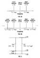
- FIGS. 2A and 2Billustrate exemplary spectral components in modulated optical signals.
- FIG. 3shows one exemplary 3-level atomic energy structure for the atoms in the atomic clock to provide the atomic frequency reference.
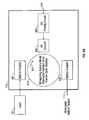
- FIG. 4shows one example of a self-oscillating OEO-based atomic clock.
- FIGS. 5 and 6show two OEO-based atomic clocks with a laser stabilization module based on the same atomic frequency reference.
- FIGS. 7, 8 A, 8 B, 9 , 10 , 11 , 12 , 13 A, and 13 Bshow various whispering-gallery-mode micro cavities and designs for compact OEO-based atomic clocks.
- FIG. 1shows one implementation of a device 100 that has an OEO and a control mechanism to lock the oscillation frequency of the OEO to an atomic transition.
- the OEOreceives an optical beam 102 at a carrier frequency ( ⁇ o ) produced by a laser 101 and uses an electrically controllable optical modulator 110 to modulate the laser beam 102 at a modulation frequency ( ⁇ mod ).
- the optical modulator 110may operate in response to an electrical modulation signal 128 applied to its port 112 and may also be configured to receive a DC bias signal 152 at its port 111 .
- the biascan shift the operating point of the modulator 110 to change the modulation frequency.
- the operation of the modulator 110produces a modulated optical signal 114 which includes multiple spectral components caused by the modulation.
- the optical modulator 110may be an amplitude modulator which periodically changes the amplitude of the optical signal, or a phase modulator which periodically changes the phase of the optical signal.
- the amplitude modulationproduces an upper modulation sideband (+1) and a lower modulation sideband ( ⁇ 1), both shifted from the carrier frequency ( ⁇ o ) by the same amount, i.e., the modulation frequency ( ⁇ mod ).
- the modulation frequency ( ⁇ mod )the modulation frequency
- FIG. 2Billustrates the spectral components of a phase-modulated signal 114 . Two immediate adjacent bands are separated by the modulation frequency ( ⁇ mod ).
- the OEOmay include at least one active opto-electronic feedback loop that comprises an optical part and an electrical part interconnected by an optical-to-electrical conversion element such as a photo-detector 124 .
- An optical splitter 115may be used to split the modulated signal 114 into a signal 117 for the opto-electronic feedback loop and a signal 116 for a frequency reference module that provides the atomic transitions for stabilizing the OEO.
- the splitter 115may also be used to produce an optical output of the device 100 .
- the optical section of the opto-electronic feedback loopis used to produce a signal delay in the modulation signal 128 by having an optical delay element 120 , such as a fiber loop or an optical resonator.
- the total delay in the opto-electronic feedback loopdetermines the mode spacing in the oscillation modes in the OEO.
- a long delayreduces the linewidth of the OEO modes and the phase noise.
- the high Q factor of the optical resonatorprovides a long energy storage time to produce an oscillation of a narrow linewidth and low phase noise. Different from other optical delay elements, the resonator as a delay element requires mode matching conditions.
- the laser carrier frequency of the laser 101should be within the transmission peak of the resonator to provide sufficient gain.
- the resonatormay be actively controlled to adjust its length to maintain this condition since the laser 101 is stabilized.
- the mode spacing of the optical resonatoris equal to one mode spacing, or a multiplicity of the mode spacing, of the opto-electronic feedback loop.
- the oscillating frequency of the OEOis equal to one mode spacing or a multiple of the mode spacing of the optical resonator.
- the optical resonator for the delay element 120may be implemented in a number of configurations, including, e.g., a Fabry-Perot resonator, a fiber ring resonator, a micro resonator that includes a portion of the equator of a sphere to whispering-gallery modes (such as a disk or a ring cavity) and a non-spherical cavity that is axially symmetric.
- the non-spherical resonatormay be formed by distorting a sphere to a non-spherical geometry to purposely achieve a large eccentricity, such as an oblate spheroidal microcavity or microtorus formed by revolving an ellipse around a symmetric axis along the short elliptical axis.
- the optical coupling for a whisper gallery mode cavitycan be achieved by evanescent coupling.
- a tapered fiber tip, a micro prism, an coupler formed from a photonic bandgap material, or other suitable optical couplersmay be used.
- the electrical section of the opto-electronic loopmay include an amplifier 125 , and an electrical bandpass filter 126 to select a single OEO mode to oscillate.
- a signal couplermay be added in the electrical section to produce an electrical output.
- the output of the photodetector 124is processed by this electrical section to produce the desired modulation signal 128 to the optical modulator 110 .
- the loopproduces a desired delay and feeds the electrical signal in phase to the modulator to generate and sustain both optical modulation and electrical oscillation when the total loop gain of the active opto-electronic loop exceeds the total loss.
- Two or more feedback opto-electronic loops with different loop delaysmay be implemented to provide additional tuning capability and flexibility in the OEO.
- the device 100implements a frequency reference module to form a phase lock loop to dynamically stabilize the OEO oscillation frequency to an atomic transition. Similar to the opto-electronic feedback loop, this module also operates based on a feedback control. However, different from the opto-electronic feedback loop, this feedback loop is a phase lock loop and is designed to avoid any oscillation and operates to correct the frequency drift or jitter of the oscillating OEO mode with respect to an atomic transition.
- the frequency reference module in the device 100includes an atomic cell 130 containing atoms with desired atomic transitions.
- the optical signal 116is sent into the cell 130 and the optical transmission 132 is used as an optical monitor signal for monitoring the frequency change in the OEO loop.
- the cell 130operates in part as an atomic optical filter because it is a narrow bandpass filter to transmit optical energy in resonance with an atomic transition.
- the cell 130also operates as a frequency reference because the optical monitor signal 132 includes information about the deviation of the OEO oscillating frequency from a desired oscillating frequency based on a frequency corresponding to a fixed separation between two energy levels in the atoms. Under the configuration in FIG. 1 where the atomic cell 130 is outside the OEO loop, this information in the optical monitor signal 132 needs to be retrieved by a differentiation method as described below.
- the frequency reference modulefurther includes a differential detector that compares the optical signal in the optical section of the OEO loop and the optical monitor signal 132 to obtain the frequency deviation in the OEO oscillating frequency.
- This differential detectorincludes two optical detectors 141 and 142 and an electrical element 150 that subtracts the two detector outputs.
- the element 150may be, e.g., a signal mixer or a differential amplifier.
- An optical splitter 123may be placed in the optical section of the OEO loop to split a portion of the modulated optical signal into the detector 141 .
- the difference of the signals from the detectors 141 and 142is the differential signal 152 which is used to control the DC bias of the optical modulator 110 .
- a phase lock loop circuitmay be implemented to perform the actual control over the DC bias in response to the signal 152 .
- the optical splitter 123 and the optical detector 141may be eliminated. Instead, a portion of the output from the detector 124 may be split off and amplified if needed to feed into the element 150 as one of the two input signals for generating the signal 152 .
- An example of such implementationis shown in FIG. 5 .
- the atoms in the atomic cell 130are selected to have three energy levels capable of producing a quantum interference effect, “electromagnetically induced transparency.”
- FIG. 3illustrates one example of the three energy levels 310 , 320 , and 330 in a suitable atom.
- the energy levels 310 and 320are two lower energy levels such as ground state hyperfine levels and the energy level 330 is a higher excited state level common to and shared by both levels 310 and 320 .
- Optical transitions 331 and 332are permissible via dipole transitions from both ground states 310 and 320 to the excited state 330 , respectively. No optical transition, however, is permitted between the two ground states 310 and 320 .
- the non-radiative relaxation rate between the two lower states 310 and 320is small and is practically negligible in comparison with the decay rates from the excited state 330 to the ground states 310 and 320 .
- the difference in frequency between the two optical transitions 331 and 332corresponds to a desired modulation frequency ( ⁇ mod ) in the electrical domain, e.g., the RF, microwave, or millimeter spectral range.
- this desired modulation frequencyis the gap 312 between the two lower states 310 and 320 .
- Examples for such atomsinclude the alkali atoms, such as cesium with a gap of about 9.2 GHz between two hyperfine ground states and rubidium with a gap of about 6.8 GHz between two hyperfine ground states.
- alkali atomssuch as cesium with a gap of about 9.2 GHz between two hyperfine ground states and rubidium with a gap of about 6.8 GHz between two hyperfine ground states.
- Different atoms with different energy level structuresmay be selected for different OEOs to operate at different modulation frequencies.
- an electron in the ground state 310can absorb a photon in resonance with the transition 331 to become excited from the ground state 310 to the excited state 330 .
- an electron in the ground state 320can be excited to the excited state 330 by absorbing a photon in resonance with the transition 332 .
- an electroncan decay to either of the ground states 310 and 320 by emitting a photon. If only one optical field is present and is in resonance with either of the two optical transitions, e.g., the transition 331 , all electrons will be eventually transferred from one ground state 310 in the optical transition 331 to the other ground state 320 not in the optical transition 331 . Hence, the atomic cell 130 will become transparent to the beam in resonance with the transition 331 .
- the two ground states 310 and 320are no longer isolated from each other.
- a quantum-mechanical coherent population trappingoccurs in which the two ground states 310 and 320 are quantum-mechanically interfered with each other to form an out-of-phase superposition state and become decoupled from the common excited state 330 .
- the atomic cell 130becomes transparent to both optical fields that are respectively in resonance with the transitions 331 and 332 .
- the atoms in the ground states 310 and 320become optically absorbing again.
- This electromagnetically induced transparencyhas a very narrow transmission spectral peak with respect to the frequency detuning of either of the two simultaneously-applied optical fields.
- the narrow transmission peakis present in the optical monitor signal 132 that transmits through the cell 130 .
- the above differential detection with the differential detectoruses the optical signal in the opto-electronic loop as a reference to determine the direction and the amount of the deviation of the optical frequencies of the two optical fields. Assuming the laser 101 is stabilized at a proper carrier frequency ( ⁇ o ) to cause the double resonance condition for the electromagnetically induced transparency, any deviation from the resonance condition should be caused by the shift or fluctuation in the OEO loop.
- the DC bias of the optical modulator 110is adjusted accordingly to correct the deviation in real time.
- This feedback operationlocks the oscillating frequency of the OEO at the frequency separation 312 between the two optical transitions 331 and 332 which is the energy separation between the two ground states 310 and 320 in this particular energy structure shown in FIG. 3 .
- the device 100operates as an atomic clock.
- the laser 101may be tuned to a resonance with either the transition 331 or the transition 332 while the lower or the upper sideband is in resonance with the other transition.
- any two immediate adjacent bands in the modulated optical signal 114may be used, it is usually practical to use the carrier band and another strong sideband.
- Atoms with other atomic energy structuresmay also be used for the atomic cell 130 .
- the 3-level energy structure in FIG. 3 where two lower states share one common excited stateis referred to as the ⁇ configuration.
- atoms with two excited states sharing a common ground state in a V configurationmay also be used.
- a consecutive three energy levels in a ladder configurationmay also be used, where the middle energy level is the excited state in a first optical transition with the lowest energy level as the corresponding lower state and is also the lower state for a second optical transition with the highest level as the corresponding excited state.
- Atoms in the cell 130may be in the vapor phase, or may be embedded in a suitable solid-state material which provides a matrix to physically hold the atoms so that a sufficiently narrow atomic transition can be obtained.
- the atomsare sealed in the cell 130 in vacuum under an elevated temperature to obtain a sufficient atomic density in the cell.
- FIG. 4shows another implementation where the atomic cell 130 is inserted in the optical section of the loop in an OEO 400 to as a narrow-band optical filter.
- the operation principle of this designis similar to that of the device 100 in FIG. 1 except that the differential detection and its feedback loop are eliminated.
- the atomic cell 130 in the OEO loopnow operates to directly filter the optical signal to transmits only the optical signal that satisfies the double-resonance Ramen condition. Any other optical signals are rejected by the atomic cell 130 .
- the OEO loopcan only provide a sufficient loop gain to amplify and sustain the signal at an oscillating frequency equal to the frequency difference of the two optical transitions for the electromagnetically induced transparency.
- the frequency locking to the atomic frequency referenceis built into the OEO loop without external differential detection implemented in FIG. 1 .
- the OEO in FIG. 4is a self-oscillating atomic clock. This design greatly simplifies the device structure and can achieve the same stabilized operation as the device 100 in FIG. 1 if the oscillating frequency of the OEO fluctuates or drifts within a small range in which the optical transmission of the cell 130 is sufficient to maintain the overall loop gain to be greater than the loop loss.
- the frequency variation of the OEOis greater than the spectral range in the transmission of the atomic cell 130 that can sustain the oscillation, the OEO needs to be adjusted to re-establish the oscillation and the automatic frequency locking to the atomic reference.
- the device 100 in FIG. 1can automatically correct such a large variation in frequency by virtue of having the phase lock loop based on the differential detection that is external to the OEO loop.
- FIGS. 5 and 6illustrate two implementations for OEOs based on the designs in FIGS. 1 and 4, respectively.
- the OEO in FIG. 5uses an electrical signal splitter at the output of the photodetector 142 to produce a signal 510 .
- An optical frequency lock unit 520receives and processes this signal 510 to produce an error signal that represents the deviation of the laser carrier frequency from a desired carrier frequency.
- a feedback control signal 522is generated based on the error signal by the unit 520 to adjust the laser frequency of the laser 101 .
- the adjustment to the laser 101may be made in various ways to tune its laser frequency depending on the specific laser configuration. For a simple diode laser, for example, the driving current, the diode temperature, or both may be adjusted in response to the control signal 522 to tune the laser frequency.
- the laser locking mechanism in FIG. 6is similar except that the feedback signal 510 is split from the output of the detector 124 in the OEO loop. It is also contemplated that other suitable laser stabilization methods may also be used to control the laser 101 . For example, a laser control may use a frequency reference independent from the atomic frequency reference provided by the atoms in the atomic cell 130 .
- the optical modulator 110 in OEOs in FIGS. 1 and 4 - 6may be implemented in various configurations.
- the widely-used Mach-Zehnder modulators using electro-optical materialscan certainly be used as the modulator 110 .
- Such conventional modulatorsgenerally are bulky and are not power efficient.
- WGMswhispering gallery modes
- FIG. 7shows one exemplary OEO 700 that uses a micro WGM cavity 710 formed of an electro-optical material as both an intensity optical modulator and an electrical filter in the OEO loop.
- the WGM cavity 710is further used as an optical delay element in the OEO loop due to its large quality factor Q so that a simple optical loop 120 may be used to provide an optical feedback without a separate optical delay element.
- a substrate 701is provided to support the micro cavity 710 and other components of the OEO 700 .
- the laser 101may be either integrated on the substrate 701 or separated from the rest of the OEO as illustrated.
- the geometry of the cavity 710is designed to support one or more WG modes and may be a micro sphere, a cavity formed of a partial sphere that includes the equator such as a disk and a ring, or a non-spherical microcavity.
- An electrical control 712is formed on the cavity 710 to apply the control electrical field in the region where the WG modes are present to modulate the index of the electro-optical material to modulate the amplitude of the light.
- the electrical control 712generally may include two or more electrodes on the cavity 710 .
- such electrodesform an RF or microwave resonator to apply the RF or microwave signal to co-propagate along with the desired optical WG mode to modulate the light.
- Such an RF or microwave resonatorby itself also operates as an electrical signal filter to filter the electrical signal in the OEO loop. Hence, there would be no need for a separate filter 126 as shown in FIG. 1.
- a DC bias electrode 711may also be formed on the cavity 710 to control the DC bias of the modulator.
- the OEO 700includes an optical coupler 720 to evanescently couple input light from the laser 101 into the cavity 710 and also to extract light out of the WG mode from the cavity to produce the optical output, the optical feedback to the OEO loop and the optical monitor signal to the atomic cell 130 .
- a micro prismis shown as an example of such an evanescent coupler.
- two evanescent couplersmay be used: one for the input and another for the output.
- An optical splitter 115is used to split the modulated optical signal output by the cavity 710 to both the optical loop 120 such as a fiber loop and the atomic cell 130 .
- the splitter 115may also produce an optical output for the OEO.
- a photodetector 124is connected to the optical delay 120 to convert the optical signal 117 into an electrical detector signal and sends the detector signal, after amplification if needed, to the electrical control 712 for controlling the optical modulation in the cavity 710 .
- the photodetector 142converts the optical monitor signal 132 transmitted through the cell 130 into the signal 152 which is used to control the DC bias of the optical modulation.
- a laser stabilization mechanismeither based on or independent from the atomic cell 130 may be included to stabilize the laser 101 .
- the above optical modulation in the WG cavity 710is based on the concept that the optical resonance condition of an optical resonator can be controlled to modulate light in the resonator.
- An optical wave in a supported resonator modecirculates in the resonator.
- the optical resonatoroperates in resonance and optical energy accumulates inside the resonator with a minimum loss. If the optical energy is coupled out of the resonator under this resonance condition, the output of the resonator is maximized.
- the recirculating wave in the resonatorhas a phase delay other then N2 ⁇
- the amount of optical energy accumulated in the resonatoris reduced and so is the coupled output.
- the phase delay in the optical cavitycan be modulated, a modulation on the output from an optical resonator can be achieved.
- the modulation on the phase delay of recirculating wave in the cavityis equivalent to a shift between a phase delay value for a resonance condition and another different value for a non-resonance condition.
- the initial value of phase delayi.e. detuning from resonance
- FIG. 8Ashows a general design of this type of optical modulators based on a WGM cavity 810 formed from any electro-optic material such as lithium niobate.
- the phase delay of the optical feedbacki.e. positions of optical cavity resonances
- An external electrical signalis used to modulate the optical phase in the resonator to shift the whispering-gallery mode condition and hence the output coupling.
- Such an optical modulatorcan operate at a low operating voltage, in the millivolt range, and may be used to achieve a high modulation speed at tens of gigahertz or higher, all in a compact package.
- two optical couplers 821 and 822are placed close to the resonator 810 as optical input coupler and output coupler, respectively.
- An input optical beam from the laser 101is coupled into the resonator 810 as the internally-circulating optical wave 812 in the whispering gallery modes by the coupler 821 .
- the evanescent fields at the surface of the spheredecays exponentially outside the sphere.
- the output coupler 822couples a portion of the circulating optical energy in the resonator 810 , also through the evanescent coupling, to produce an output beam 114 .
- the optical coupler 821may also be used to produce the output 114 as shown in FIG. 7 .
- An electrical coupler 830is placed near the resonator 810 to couple an electrical wave which causes a change in the dielectric constant due to the electro-optic effect.
- An electronic driving circuit 840is implemented to supply the electrical wave to the electrical coupler 830 .
- a control signal 128 from the detector 124 in the OEO loopcan be fed into the circuit 840 to modulate the electrical wave. This modulation is then transferred to a modulation in the optical output 114 of the resonator 810 .
- the resonator 810 with a high Q factorhas a number of advantages. For example, the repetitive circulation of the optical signal in the WG mode increases the effective interaction length for the electro-optic modulation.
- the resonator 810can also effectuate an increase in the energy storage time for either the optical energy or the electrical energy and hence reduce the spectral linewidth and the phase noise.
- the mode matching conditionsmake the optical modulator operate as a signal filter so that only certain input optical beam can be coupled through the resonator 810 to produce a modulated output by rejecting other signals that fail the mode matching conditions.
- FIG. 8Bshows another light modulator in a modulator housing 880 based on the design in FIG. 8 A.
- Optical fibers 851 and 854are used to guide input and output optical beams 102 , 114 , respectively.
- Microlenses 852 and 853such as gradient index lenses, are used to couple optical beams in and out of the fibers.
- Two prisms 821 and 822operate as the evanescent optical couplers to provide evanescent coupling with the whispering gallery mode resonator 810 .
- a RF microstrip line electrode 860is combined with the resonator 810 to form a RF resonator to support the electrical modes.
- An input RF coupler 861 formed from a microstrip lineis implemented to input the electrical energy into the RF resonator.
- a circuit board 870is used to support the microstrip lines and other RF circuit elements for the modulator.
- This modulatoralso includes a second RF coupler 862 , which may be formed from a microstrip line on the board 870 , to produce a RF output. This signal can be used as a monitor for the operation of the modulator or as an electrical output for further processing or driving other components.
- FIG. 9illustrates an exemplary integrated OEO 900 with all its components fabricated on a semiconductor substrate 901 .
- a micro WGM cavity 940is used as an optical delay element equivalent to the delay 120 in FIG. 1 .
- the integrated OEO 900also includes a semiconductor laser 101 , a semiconductor electro-absorption modulator 920 , a first waveguide 930 , a second waveguide 950 , and a photodetector 960 .
- the detector 960is equivalent to the detector 124 in FIG. 1 .
- An electrical link 970e.g., a conductive path, is also formed on the substrate 901 to electrically couple the detector 960 to the modulator 920 .
- the micro resonator 940is used as a high-Q energy storage element to achieve low phase noise and micro size.
- a RF filter 126may be disposed in the link 970 to ensure a single-mode oscillation. In absence of such a filter, a frequency filtering effect can be achieved by narrow band impedance matching between the modulator 920 and the detector 960 .
- Both waveguides 930 and 950have coupling regions 932 and 952 , respectively, to provide desired evanescent optical coupling at two different locations in the micro resonator 940 .
- the first waveguide 930has one end coupled to the modulator 920 to receive the modulated optical output and another end to provide an optical output of the OEO 900 .
- the second waveguide 950couples the optical energy from the micro resonator 940 and delivers the energy to the detector 960 .
- the complete closed opto-electronic loopis formed by the modulator 920 , the first waveguide 930 , the micro resonator 940 , the second waveguide 950 , the detector 960 , and the electrical link 970 .
- the phase delay in the closed loopis set so that the feedback signal from the detector 960 to the modulator 920 is positive.
- the total open loop gainexceeds the total losses to sustain an opto-electronic oscillation.
- the proper mode matching conditions between the resonator 940 and the total loopare also required. Since the laser carrier frequency should be at the transmission peak of the resonator 940 to sustain the oscillation, it may be desirable to dynamically adjust the cavity length of the micro resonator 940 to maintain this condition.
- an electrical signal amplifier 125may be connected between the detector 960 and the modulator 920 .
- a high-power elementcan be undesirable in a highly integrated on-chip design such as the OEO 900 .
- the high power of the amplifiermay cause problems due to its high thermal dissipation.
- the amplifiermay introduce noise or distortion, and may even interfere with operations of other electronic components on the chip.
- One distinctive feature of the OEO 900is to eliminate such a signal amplifier in the link 970 by matching the impedance between the electro-absorption modulator 920 and the photodetector 960 at a high impedance value.
- the desired matched impedanceis a value so that the photovoltage transmitted to the modulator 920 , without amplification, is sufficiently high to properly drive the modulator 920 .
- this matched impedancemay be about 1 kilo ohm or several kilo ohms.
- the electrical link 970can be used, without a signal amplifier, to directly connect the photodetector 960 and the modulator 920 to preserve their high impedance.
- Such a direct electrical link 970can ensure the maximum energy transfer between the two devices 920 and 960 .
- a pair of a detector and a modulator that are matched at 1000 ohmmay have a voltage gain of 20 times that of the same pair that are matched at 50 ohm.
- FIG. 10shows another integrated coupled OEO 1000 suitable for implementing compact atomic clocks.
- This OEOis formed on a semiconductor substrate 1001 and includes two waveguides 1010 and 1020 that are coupled to a high Q micro WGM cavity 1002 .
- the waveguides 1010 and 1020have angled ends 1016 and 1026 , respectively, to couple to the micro cavity 1002 by evanescent coupling.
- the other end of the waveguide 1010includes an electrical insulator layer 1011 , an electro-absorption modulator section 1012 , and a high reflector 1014 .
- This high reflector 1014operates to induce pulse colliding in the modulator 1012 and thus enhance the mode-locking capability.
- the other end of the waveguide 1020is a polished surface 1024 and is spaced from a photodetector 1022 by a gap 1021 .
- the surface 1024acts as a partial mirror to reflect a portion of light back into the waveguide 1020 and to transmit the remaining portion to the photodetector 1022 to produce an optical output and an electrical signal.
- An electrical link 1030is coupled between the modulator 1012 and photodetector 1022 to produce an electrical output and to feed the signal and to feed the electrical signal to control the modulator 1012 .
- An optical loopis in a Fabry-Perot resonator configuration, which is formed between the high reflector 1014 and the surface 1024 of the waveguide 1020 through the modulator 1012 , the waveguide 1010 , the micro cavity 1002 , and the waveguide 1020 .
- the gap 1021 , the detector 1022 , and the electrical link 1030forms another opto-electronic loop that is coupled to the above optical loop.
- the above optical loopforms a laser to replace the separate laser 101 in other OEOs described in this application.
- the waveguides 1010 and 1020are optically active and doped within ions to also function as the gain medium so that the optical loop operates as a laser when activated by a driving current. This current can be injected from proper electrical contacts coupled to an electrical source.
- the gain of the laseris modulated electrically by the modulator 1012 in response to the electrical signal from the photodetector 1022 .
- the two waveguides 1010 and 1020may be positioned adjacent and parallel to each other on the substrate 1001 so that the photodetector 1022 and the modulator 1012 are close to each other. This arrangement facilitates wire bonding or other connection means between the photodetector 1022 and the modulator 1012 .
- the photodetector 1022may be structurally identical to the electro-absorption modulator 1012 but is specially biased to operate as a photodetector. Hence, the photodetector 1022 and the modulator 1012 have a similar impedance, e.g., on the order of a few kilo ohms, and thus are essentially impedance matched. Taking typical values of 2 volts modulator switching voltage, 1 kilo ohm for the impedance of the modulator 1012 and photodetector 1022 , the optical power required for the sustained RF oscillation is estimated at about 1.28 mW when the detector responsivity is 0.5 A/W. Such an optical power is easily attainable in semiconductor lasers. Therefore, under the impedance matching condition, a RF amplifier may be eliminated in the electrical link 1030 as in the integrated OEO 900 in FIG. 9 .
- the atomic cell 130may be inserted into the optical path to form a compact self-oscillating atomic clock as shown in FIGS. 4 and 6.
- FIG. 11further shows an exemplary integrated self-oscillating atomic clock 1100 based on the design in FIG. 6 .
- the WGM cavity modulator in FIG. 7is used to perform both the optical modulation and the optical delay in the OEO loop.
- the laser beam 102 from the laser 101is collimated by a lens 110 before being coupled into the WGM cavity 710 .
- the circuit 1120includes both the electrical section of the OEO loop and the laser frequency control circuit 520 .
- the atomic cell 130may be used in a separate phase-lock loop for locking the OEO to the atomic frequency reference as illustrated in FIGS. 1 and 5.
- the above examples for compact and integrated OEO-based atomic clocksillustrate different approaches to the device integration.
- One approachuses compact components to reduce the overall physical size of the OEO, such as using miniaturized devices for the optical delay element 120 or the optical modulator 110 .
- the OEO devices in FIGS. 7, 8 A, 8 B, 9 , 10 , and 11represent examples in this approach, where either a WGM micro resonator or an integrated semiconductor electro-absorption modulator is used to replace conventional bulky modulators.
- the WGM micro resonatoris also used as to cause the desired optical delay in the OEO loop to avoid bulky optical delay elements.
- the optical modulator 110 and the optical delay element 120are integrated into a single unit within the OEO to miniaturize the whole device.
- FIGS. 7, 8 A, 8 B, and 11represent examples in this approach.
- the modulated optical output 114may be directly fed into the optical detector 124 in the OEO loop without going through another optical delay element due to the high Q value of the resonator 810 .
- FIG. 12further shows an OEO-based atomic clock under this approach.
- a special optical modulator 1210is used to provide both optical modulation and the optical delay.
- the OEO loopis formed by the modulator 1210 and the detector 124 .
- This modulator 1210may be implemented by, e.g., the WGM resonator modulator in FIGS.
- An optional laser frequency feedback loop for stabilizing the laser 101is also shown in FIG. 12 .
- the signal mixer 150is shown to receive one input from the detector 142 and another input from the phase-lock loop coupled between the modulator 1210 and the mixer 150 .
- the second input to the mixer 150may be taken from the output of the detector 124 in the OEO loop.
- the output from the optical frequency lock circuit 420may be combined with the signal 152 to control the modulator 1210 .
- FIG. 10also suggests yet another approach to the integration of the OEO-based atomic clocks where the laser source that powers the OEO and the optical modulator may be integrated as a single unit.
- the electro-absorption modulator 1012is within the laser resonator formed by the reflectors 1014 and 1024 .
- This combination of the laser and the optical modulatormay be implemented in a modulated laser such as a diode laser or a diode-based laser where the driving current of the laser may be directly modulated to change the internal gain of the laser and thus produce a modulated optical output.
- FIGS. 13A and 13Bshow two exemplary OEO-based atomic clocks where a single directly modulated laser 1310 is used to both produce the laser carrier and provide the modulation of the laser carrier.
- OEO 1301 in FIG. 13Ahas an external frequency lock loop with an atomic cell.
- OEO 1302 in FIG. 13Bis a self-oscillating OEO.
- the laser 1310 in both devices 1301 and 1302is a tunable laser and can be directly modulated.
- the optical delay element 120may be implemented with a WGM microcavity.
- two separate feedback loopsare used: one is the OEO loop with the optical delay element 120 and another is the phase-lock loop for locking the modulation frequency of the modulated laser output 114 to a desired atomic frequency reference in the atomic cell 130 .
- the phase-lock control and the OEO loop feedback signal 128may be combined to control the modulation of the laser 101 .
- another phase-look loopmay be used to stabilize the laser carrier frequency of the laser 1310 .
- the atomic cell 130is in the optical section of the OEO loop so that the feedback signal 128 in the OEO loop allows the OEO to be locked to the atomic frequency reference provided by the atomic cell 130 if the carrier frequency of the laser 1310 is stabilized.
- the additional phase-lock loopbased on a signal 510 split from the output of the detector 124 may be used to stabilize the laser carrier frequency of the laser 1310 by, e.g., controlling the cavity length of the laser.
Landscapes
- Physics & Mathematics (AREA)
- General Physics & Mathematics (AREA)
- Optical Modulation, Optical Deflection, Nonlinear Optics, Optical Demodulation, Optical Logic Elements (AREA)
- Stabilization Of Oscillater, Synchronisation, Frequency Synthesizers (AREA)
- Lasers (AREA)
- Inductance-Capacitance Distribution Constants And Capacitance-Resistance Oscillators (AREA)
Abstract
Description
Claims (38)
Priority Applications (1)
| Application Number | Priority Date | Filing Date | Title |
|---|---|---|---|
| US10/410,873US6762869B2 (en) | 2002-04-09 | 2003-04-09 | Atomic clock based on an opto-electronic oscillator |
Applications Claiming Priority (2)
| Application Number | Priority Date | Filing Date | Title |
|---|---|---|---|
| US37105502P | 2002-04-09 | 2002-04-09 | |
| US10/410,873US6762869B2 (en) | 2002-04-09 | 2003-04-09 | Atomic clock based on an opto-electronic oscillator |
Publications (2)
| Publication Number | Publication Date |
|---|---|
| US20040109217A1 US20040109217A1 (en) | 2004-06-10 |
| US6762869B2true US6762869B2 (en) | 2004-07-13 |
Family
ID=29250628
Family Applications (1)
| Application Number | Title | Priority Date | Filing Date |
|---|---|---|---|
| US10/410,873Expired - LifetimeUS6762869B2 (en) | 2002-04-09 | 2003-04-09 | Atomic clock based on an opto-electronic oscillator |
Country Status (8)
| Country | Link |
|---|---|
| US (1) | US6762869B2 (en) |
| EP (1) | EP1493212B1 (en) |
| JP (1) | JP4163630B2 (en) |
| AT (1) | ATE445922T1 (en) |
| AU (1) | AU2003224911A1 (en) |
| CA (1) | CA2478347C (en) |
| DE (1) | DE60329666D1 (en) |
| WO (1) | WO2003088472A2 (en) |
Cited By (68)
| Publication number | Priority date | Publication date | Assignee | Title |
|---|---|---|---|---|
| US20020176452A1 (en)* | 2001-03-16 | 2002-11-28 | Lin Hong Tony | Digital control of actively mode-locked lasers |
| US20030219045A1 (en)* | 2002-05-14 | 2003-11-27 | Lambda Crossing Ltd. | Tunable laser using microring resonator |
| US20040100675A1 (en)* | 2002-11-22 | 2004-05-27 | Matsko Andrey B. | Active mode-locked lasers and other photonic devices using electro-optic whispering gallery mode resonators |
| US20040202430A1 (en)* | 2003-04-03 | 2004-10-14 | Lambda Crossing Ltd. | Integrated optical filters utilizing resonators |
| US20040218880A1 (en)* | 2002-05-28 | 2004-11-04 | Matsko Andrey B | Electro-optical modulation and other optical applications using poled optical whispering gallery mode resonators |
| US20040240781A1 (en)* | 2002-05-17 | 2004-12-02 | Anatoliy Savchenkov | Optical filter having coupled whispering-gallery-mode resonators |
| US20050017816A1 (en)* | 2003-06-03 | 2005-01-27 | Vladimir Ilchenko | Resonant impedance matching in microwave and RF device |
| US20050063034A1 (en)* | 2003-08-04 | 2005-03-24 | Lutfollah Maleki | Opto-electronic feedback for stabilizing oscillators |
| US20050128566A1 (en)* | 2003-02-03 | 2005-06-16 | Anatoliy Savchenkov | Tunable optical filters having electro-optic whispering-gallery-mode resonators |
| US20050147355A1 (en)* | 2003-07-03 | 2005-07-07 | Vladimir Ilchenko | Optical coupling for whispering-gallery-mode resonators via waveguide gratings |
| US20050175358A1 (en)* | 2004-01-12 | 2005-08-11 | Vladimir Ilchenko | Tunable radio frequency and microwave photonic filters |
| US20050185681A1 (en)* | 2003-10-15 | 2005-08-25 | Vladimir Ilchenko | Continuously tunable coupled opto-electronic oscillators having balanced opto-electronic filters |
| US20050220411A1 (en)* | 2004-03-22 | 2005-10-06 | Vladimir Ilchenko | Optical waveguide coupler for whispering-gallery-mode resonators |
| US20050286602A1 (en)* | 2004-06-09 | 2005-12-29 | Deana Gunn | Integrated opto-electronic oscillators |
| US7061335B2 (en) | 2004-04-15 | 2006-06-13 | Oewaves, Inc. | Processing of signals with regenerative opto-electronic circuits |
| US7187870B2 (en) | 2003-10-15 | 2007-03-06 | Oewaves, Inc. | Tunable balanced opto-electronic filters and applications in opto-electronic oscillators |
| US7218662B1 (en) | 2004-02-12 | 2007-05-15 | Oewaves, Inc. | Coupled opto-electronic oscillators with low noise |
| US7248763B1 (en) | 2003-07-03 | 2007-07-24 | Oewaves, Inc. | Optical resonators with reduced OH-content |
| US7283707B1 (en) | 2001-07-25 | 2007-10-16 | Oewaves, Inc. | Evanescently coupling light between waveguides and whispering-gallery mode optical resonators |
| US20080001062A1 (en)* | 2004-06-09 | 2008-01-03 | Deana Gunn | Integrated opto-electronic oscillators |
| US20080075464A1 (en)* | 2006-09-05 | 2008-03-27 | Oewaves, Inc. | Wideband receiver based on photonics technology |
| US7362927B1 (en) | 2004-06-01 | 2008-04-22 | Oewaves, Inc. | Tunable RF or microwave photonic filters using temperature-balanced whispering gallery mode optical resonators |
| US7369290B1 (en)* | 2003-03-19 | 2008-05-06 | Photonic Systems, Inc. | Modulator bias control |
| US7389053B1 (en) | 2003-10-15 | 2008-06-17 | Oewaves, Inc. | Tunable filtering of RF or microwave signals based on optical filtering in Mach-Zehnder configuration |
| US7440651B1 (en) | 2004-11-17 | 2008-10-21 | California Institute Of Technology | Single mode whispering-gallery-mode resonator |
| US20080310463A1 (en)* | 2007-06-13 | 2008-12-18 | Lutfollah Maleki | Tunable Lasers Locked to Whispering Gallery Mode Resonators |
| US20090097516A1 (en)* | 2007-06-13 | 2009-04-16 | Lutfollah Maleki | RF and microwave receivers based on electro-optic optical whispering gallery mode resonators |
| US20090128820A1 (en)* | 2007-11-20 | 2009-05-21 | Epson Toyocom Corporation | Optical system and atomic oscillator background |
| US20090135860A1 (en)* | 2007-11-13 | 2009-05-28 | Lutfollah Maleki | Cross Modulation-Based Opto-Electronic Oscillator with Tunable Electro-Optic Optical Whispering Gallery Mode Resonator |
| US20090208205A1 (en)* | 2007-11-13 | 2009-08-20 | Danny Eliyahu | Photonic Based Cross-Correlation Homodyne Detection with Low Phase Noise |
| US20090256638A1 (en)* | 2008-03-28 | 2009-10-15 | Michael Rosenbluh | Atomic frequency standard based on enhanced modulation efficiency semiconductor lasers |
| US7630417B1 (en)* | 2004-06-24 | 2009-12-08 | California Institute Of Technology | Crystal whispering gallery mode optical resonators |
| US20090310629A1 (en)* | 2008-03-11 | 2009-12-17 | Lute Maleki | Optical locking based on optical resonators with high quality factors |
| US20100118375A1 (en)* | 2008-11-13 | 2010-05-13 | Oewaves, Inc. | Tunable Single Sideband Modulators Based On Electro-Optic Optical Whispering Gallery Mode Resonators and Their Applications |
| US20100135342A1 (en)* | 2008-07-03 | 2010-06-03 | Jeffrey Livas | System and Method for Tuning Adjusting the Central Frequency of a Laser While Maintaining Frequency Stabilization to an External Reference |
| US7929589B1 (en) | 2007-06-13 | 2011-04-19 | Oewaves, Inc. | Diffractive grating coupled whispering gallery mode resonators |
| US8089684B1 (en)* | 2008-03-14 | 2012-01-03 | Oewaves, Inc. | Photonic RF and microwave phase shifters |
| US8094359B1 (en) | 2008-05-15 | 2012-01-10 | Oewaves, Inc. | Electro-optic whispering-gallery-mode resonator devices |
| US8102597B1 (en) | 2008-05-15 | 2012-01-24 | Oewaves, Inc. | Structures and fabrication of whispering-gallery-mode resonators |
| US8111722B1 (en) | 2008-03-03 | 2012-02-07 | Oewaves, Inc. | Low-noise RF oscillation and optical comb generation based on nonlinear optical resonator |
| US8111402B2 (en) | 2008-04-03 | 2012-02-07 | Oewaves, Inc. | Optical sensing based on overlapping optical modes in optical resonator sensors and interferometric sensors |
| US8124927B2 (en) | 2007-05-29 | 2012-02-28 | California Institute Of Technology | Detecting light in whispering-gallery-mode resonators |
| US8155914B2 (en) | 2007-11-13 | 2012-04-10 | Oewaves, Inc. | Measuring phase noise in radio frequency, microwave or millimeter signals based on photonic delay |
| US8164816B1 (en) | 2007-08-31 | 2012-04-24 | California Institute Of Technology | Stabilizing optical resonators |
| US8210044B1 (en) | 2007-10-12 | 2012-07-03 | California Institute Of Technology | Covert laser remote sensing and vibrometry |
| US20120235756A1 (en)* | 2011-03-14 | 2012-09-20 | Seiko Epson Corporation | Optical module for atomic oscillator and atomic oscillator |
| US20120267509A1 (en)* | 2009-02-06 | 2012-10-25 | Seiko Epson Corporation | Quantum interference device, atomic oscillator, and magnetic sensor |
| US8331409B1 (en) | 2010-01-18 | 2012-12-11 | Oewaves, Inc. | Locking of a laser to an optical interferometer that is stabilized to a reference frequency |
| US8331008B1 (en) | 2008-10-14 | 2012-12-11 | Oewaves, Inc. | Photonic microwave and RF receivers based on electro-optic whispering-gallery-mode resonators |
| US8417076B2 (en) | 2009-06-22 | 2013-04-09 | Oewaves, Inc. | Tunable photonic microwave or radio frequency receivers based on electro-optic optical whispering gallery mode resonators |
| WO2013003859A3 (en)* | 2011-06-30 | 2013-04-18 | Oewaves, Inc. | Compact optical atomic clocks and applications based on parametric nonlinear optical mixing in whispering gallery mode optical resonators |
| US8452139B1 (en) | 2008-07-25 | 2013-05-28 | Oewaves, Inc. | Wide-band RF photonic receivers and other devices using two optical modes of different quality factors |
| US8498539B1 (en) | 2009-04-21 | 2013-07-30 | Oewaves, Inc. | Dielectric photonic receivers and concentrators for radio frequency and microwave applications |
| US20130202305A1 (en)* | 2012-02-02 | 2013-08-08 | Weimin Zhou | Method and apparatus for providing radio frequency photonic filtering |
| US8514400B2 (en) | 2010-03-23 | 2013-08-20 | Oewaves, Inc. | Optical gyroscope sensors based on optical whispering gallery mode resonators |
| US8564869B1 (en) | 2010-07-15 | 2013-10-22 | Oewaves, Inc. | Voltage controlled tunable single sideband modulators and devices based on electro-optic optical whispering gallery mode resonators |
| US8605760B2 (en) | 2010-08-10 | 2013-12-10 | Oewaves, Inc. | Feedback-enhanced self-injection locking of lasers to optical resonators |
| US8659814B2 (en) | 2011-06-23 | 2014-02-25 | Oewaves, Inc. | Parametric regenerative oscillators based on opto-electronic feedback and optical regeneration via nonlinear optical mixing in whispering gallery mode optical resonators |
| US8681827B2 (en) | 2011-05-16 | 2014-03-25 | Oewaves, Inc. | Generation of single optical tone, RF oscillation signal and optical comb in a triple-oscillator device based on nonlinear optical resonator |
| US8761603B1 (en) | 2009-02-25 | 2014-06-24 | Oewaves, Inc. | Dynamically reconfigurable sensor arrays |
| US20140200689A1 (en)* | 2013-01-11 | 2014-07-17 | The Board Of Trustees Of The Leland Stanford Junior University | Quantum computer and quantum computing using ising model |
| US8804231B2 (en) | 2011-06-20 | 2014-08-12 | Oewaves, Inc. | Stabilizing RF oscillator based on optical resonator |
| US8907276B2 (en) | 2012-04-11 | 2014-12-09 | Honeywell International Inc. | Measuring the populations in each hyperfine ground state of alkali atoms in a vapor cell while limiting the contribution of the background vapor |
| US8976822B2 (en) | 2012-03-27 | 2015-03-10 | Oewaves, Inc. | Tunable opto-electronic oscillator having optical resonator filter operating at selected modulation sideband |
| US9077354B2 (en) | 2012-04-10 | 2015-07-07 | Honeywell International Inc. | Low power reduction of biases in a micro primary frequency standard |
| US9360626B2 (en) | 2007-11-13 | 2016-06-07 | Anatoliy Savchenkov | Fiber-based multi-resonator optical filters |
| US10998376B2 (en) | 2019-01-29 | 2021-05-04 | International Business Machines Corporation | Qubit-optical-CMOS integration using structured substrates |
| US11804694B2 (en) | 2019-03-27 | 2023-10-31 | Samsung Electronics Co., Ltd. | Laser device and method of transforming laser spectrum |
Families Citing this family (35)
| Publication number | Priority date | Publication date | Assignee | Title |
|---|---|---|---|---|
| US20040208643A1 (en)* | 2002-05-13 | 2004-10-21 | Ar Card | Coherent optical receivers |
| FR2868558B1 (en)* | 2004-03-30 | 2006-06-30 | Centre Nat Rech Scient Cnrse | METHOD FOR GENERATING AN ATOMIC CLOCK SIGNAL WITH COHERENT POPULATION TRAPPING AND CORRESPONDING ATOMIC CLOCK |
| JP5568019B2 (en)* | 2008-02-07 | 2014-08-06 | ガン,ラハブ | Devices, systems, and methods for frequency generation using atomic resonators |
| US9360844B2 (en) | 2008-02-07 | 2016-06-07 | Dimension 4 Ltd. | Apparatus, system, and method of frequency generation using an atomic resonator |
| JP5290737B2 (en)* | 2008-02-08 | 2013-09-18 | 古河電気工業株式会社 | Optical-microwave oscillator and pulse generator |
| JP2011523787A (en)* | 2008-06-05 | 2011-08-18 | コーニンクレッカ フィリップス エレクトロニクス エヌ ヴィ | Atomic frequency acquisition device based on self-mixing interference |
| JP2010102045A (en)* | 2008-10-22 | 2010-05-06 | Furukawa Electric Co Ltd:The | Mode synchronization semiconductor laser |
| JP5381400B2 (en)* | 2009-02-06 | 2014-01-08 | セイコーエプソン株式会社 | Quantum interferometers, atomic oscillators, and magnetic sensors |
| JP5589166B2 (en)* | 2009-11-12 | 2014-09-17 | セイコーエプソン株式会社 | Atomic oscillator |
| JP5699467B2 (en)* | 2010-07-14 | 2015-04-08 | セイコーエプソン株式会社 | Optical module and atomic oscillator |
| JP2012256663A (en)* | 2011-06-08 | 2012-12-27 | Nec Corp | Optical amplifier and optical amplification method |
| GB2512522B (en) | 2011-12-23 | 2018-05-16 | Intel Corp | Integrated silicon optomechanical gyroscopes (OMGS) |
| CN102545042B (en)* | 2012-02-21 | 2013-04-03 | 山西大同大学 | Production method of optical microwave signal with tunable broadband frequency |
| JP6124536B2 (en)* | 2012-08-30 | 2017-05-10 | 株式会社リコー | Atomic oscillator and CPT resonance excitation method |
| KR101471716B1 (en)* | 2012-11-07 | 2014-12-11 | 홍익대학교 산학협력단 | Optoelectronic oscillator and method |
| US9088369B2 (en)* | 2012-12-28 | 2015-07-21 | Synergy Microwave Corporation | Self injection locked phase locked looped optoelectronic oscillator |
| US9094133B2 (en)* | 2013-03-12 | 2015-07-28 | Synergy Microwave Corporation | Integrated production of self injection locked self phase loop locked optoelectronic oscillator |
| SI24591A (en)* | 2013-12-24 | 2015-06-30 | Center Odliäśnosti Za Biosenzoriko, Instrumentacijo In Procesno Kontrolo | The process control and stabilization of the optoelectronic oscillator frequency |
| RU2548394C1 (en)* | 2013-12-30 | 2015-04-20 | Общество с ограниченной ответственностью "Техноскан-Лаб" (ООО "Техноскан-Лаб") | Raman fibre pulsed laser |
| CN103823356B (en)* | 2014-03-07 | 2016-04-20 | 中国科学院武汉物理与数学研究所 | Based on passive-type CPT atomic clock experimental provision and the method for PXI system |
| JP2017514111A (en) | 2014-03-19 | 2017-06-01 | オーイーウェーブス, インク.Oewaves, Inc. | Optical atomic clock |
| EP3170052B1 (en)* | 2014-07-17 | 2023-04-26 | CSEM Centre Suisse D'electronique Et De Microtechnique SA | Atomic clock |
| KR102016928B1 (en)* | 2014-10-31 | 2019-10-14 | 아이디 퀀티크 에스.에이. | Method and Apparatus for Synchronizing using Opto-electronic Oscillator |
| EP3034463B1 (en)* | 2014-12-18 | 2019-03-27 | Centre National De La Recherche Scientifique (Cnrs) | Coherent spectroscopic methods with extended interrogation times and systems implementing such |
| CN105577267B (en)* | 2014-12-30 | 2017-09-12 | 北京无线电计量测试研究所 | Optical fiber Frequency Transfer phase compensation device and method based on optical-electronic oscillator principle |
| CN105467821B (en)* | 2015-12-01 | 2018-04-06 | 北京无线电计量测试研究所 | A kind of physical system of Atomic Clocks Based on Coherent Population Trapping |
| US9885888B2 (en)* | 2016-02-08 | 2018-02-06 | International Business Machines Corporation | Integrated microwave-to-optical single-photon transducer with strain-induced electro-optic material |
| CN106025786B (en)* | 2016-07-29 | 2019-01-25 | 北京邮电大学 | A kind of photoelectric oscillator and its frequency stabilization method |
| CN108225578B (en)* | 2017-12-25 | 2020-05-12 | 中国科学技术大学 | A Dual-Laser System for Precision Measurement of Cold Atom Interferometry |
| US10727948B2 (en) | 2018-04-05 | 2020-07-28 | Nokia Solutions And Networks Oy | Communication system employing surface-coupled optical devices |
| US10411807B1 (en)* | 2018-04-05 | 2019-09-10 | Nokia Solutions And Networks Oy | Optical transmitter having an array of surface-coupled electro-absorption modulators |
| US11300682B2 (en)* | 2018-10-18 | 2022-04-12 | Bae Systems Information And Electronic Systems Integration Inc. | Multi-static and bistatic coherent LIDAR with lasers locked to a reference |
| CN110989326B (en)* | 2019-12-26 | 2021-03-30 | 中国计量科学研究院 | Local high-precision time frequency real-time comprehensive device |
| CN111834864A (en)* | 2020-07-07 | 2020-10-27 | 电子科技大学 | An optoelectronic oscillator based on phase modulation and optical filtering |
| CN112787204B (en)* | 2020-12-31 | 2022-03-01 | 武汉邮电科学研究院有限公司 | Photoelectric oscillator based on-chip integrated system and method for generating microwave signal |
Citations (11)
| Publication number | Priority date | Publication date | Assignee | Title |
|---|---|---|---|---|
| US5267072A (en) | 1991-05-20 | 1993-11-30 | The United States Of America As Represented By The Administrator Of The National Aeronautics And Space Administration | Dual frequency optical carrier technique for transmission of reference frequencies in dispersive media |
| US5340980A (en)* | 1992-01-02 | 1994-08-23 | Raytheon Company | Frequency discriminator with fiber optic delay line |
| US5723856A (en) | 1995-08-01 | 1998-03-03 | California Institute Of Technology | Opto-electronic oscillator having a positive feedback with an open loop gain greater than one |
| US5777778A (en) | 1996-01-23 | 1998-07-07 | California Institute Of Technology | Multi-Loop opto-electronic microwave oscillator with a wide tuning range |
| US5917179A (en) | 1997-05-12 | 1999-06-29 | California Institute Of Technology | Brillouin opto-electronic oscillators |
| US5929430A (en) | 1997-01-14 | 1999-07-27 | California Institute Of Technology | Coupled opto-electronic oscillator |
| US6389197B1 (en) | 1999-02-10 | 2002-05-14 | California Institute Of Technology | Coupling system to a microsphere cavity |
| US6473218B1 (en) | 1999-06-11 | 2002-10-29 | California Institute Of Technology | Light modulation in whispering-gallery-mode resonators |
| US6490039B2 (en) | 2000-08-08 | 2002-12-03 | California Institute Of Technology | Optical sensing based on whispering-gallery-mode microcavity |
| US6567436B1 (en) | 1999-01-26 | 2003-05-20 | California Institute Of Technology | Opto-electronic oscillators having optical resonators |
| US6654394B1 (en)* | 1999-07-01 | 2003-11-25 | The Research And Development Institute, Inc. | Laser frequency stabilizer using transient spectral hole burning |
Family Cites Families (2)
| Publication number | Priority date | Publication date | Assignee | Title |
|---|---|---|---|---|
| EP0842571B1 (en)* | 1995-08-01 | 2007-03-07 | California Institute Of Technology | Opto-electronic oscillator systems and their applications |
| EP1299767B1 (en)* | 2000-06-09 | 2006-08-09 | California Institute Of Technology | Acceleration-insensitive opto-electronic oscillators |
- 2003
- 2003-04-09EPEP03721605Apatent/EP1493212B1/ennot_activeExpired - Lifetime
- 2003-04-09USUS10/410,873patent/US6762869B2/ennot_activeExpired - Lifetime
- 2003-04-09JPJP2003585274Apatent/JP4163630B2/ennot_activeExpired - Fee Related
- 2003-04-09WOPCT/US2003/010983patent/WO2003088472A2/enactiveApplication Filing
- 2003-04-09DEDE60329666Tpatent/DE60329666D1/ennot_activeExpired - Lifetime
- 2003-04-09CACA002478347Apatent/CA2478347C/ennot_activeExpired - Fee Related
- 2003-04-09ATAT03721605Tpatent/ATE445922T1/ennot_activeIP Right Cessation
- 2003-04-09AUAU2003224911Apatent/AU2003224911A1/ennot_activeAbandoned
Patent Citations (11)
| Publication number | Priority date | Publication date | Assignee | Title |
|---|---|---|---|---|
| US5267072A (en) | 1991-05-20 | 1993-11-30 | The United States Of America As Represented By The Administrator Of The National Aeronautics And Space Administration | Dual frequency optical carrier technique for transmission of reference frequencies in dispersive media |
| US5340980A (en)* | 1992-01-02 | 1994-08-23 | Raytheon Company | Frequency discriminator with fiber optic delay line |
| US5723856A (en) | 1995-08-01 | 1998-03-03 | California Institute Of Technology | Opto-electronic oscillator having a positive feedback with an open loop gain greater than one |
| US5777778A (en) | 1996-01-23 | 1998-07-07 | California Institute Of Technology | Multi-Loop opto-electronic microwave oscillator with a wide tuning range |
| US5929430A (en) | 1997-01-14 | 1999-07-27 | California Institute Of Technology | Coupled opto-electronic oscillator |
| US5917179A (en) | 1997-05-12 | 1999-06-29 | California Institute Of Technology | Brillouin opto-electronic oscillators |
| US6567436B1 (en) | 1999-01-26 | 2003-05-20 | California Institute Of Technology | Opto-electronic oscillators having optical resonators |
| US6389197B1 (en) | 1999-02-10 | 2002-05-14 | California Institute Of Technology | Coupling system to a microsphere cavity |
| US6473218B1 (en) | 1999-06-11 | 2002-10-29 | California Institute Of Technology | Light modulation in whispering-gallery-mode resonators |
| US6654394B1 (en)* | 1999-07-01 | 2003-11-25 | The Research And Development Institute, Inc. | Laser frequency stabilizer using transient spectral hole burning |
| US6490039B2 (en) | 2000-08-08 | 2002-12-03 | California Institute Of Technology | Optical sensing based on whispering-gallery-mode microcavity |
Cited By (109)
| Publication number | Priority date | Publication date | Assignee | Title |
|---|---|---|---|---|
| US6839363B2 (en)* | 2001-03-16 | 2005-01-04 | Calmar Optcom, Inc. | Digital control of actively mode-locked lasers |
| US20020176452A1 (en)* | 2001-03-16 | 2002-11-28 | Lin Hong Tony | Digital control of actively mode-locked lasers |
| US7283707B1 (en) | 2001-07-25 | 2007-10-16 | Oewaves, Inc. | Evanescently coupling light between waveguides and whispering-gallery mode optical resonators |
| US20030219045A1 (en)* | 2002-05-14 | 2003-11-27 | Lambda Crossing Ltd. | Tunable laser using microring resonator |
| US6940878B2 (en)* | 2002-05-14 | 2005-09-06 | Lambda Crossing Ltd. | Tunable laser using microring resonator |
| US20040240781A1 (en)* | 2002-05-17 | 2004-12-02 | Anatoliy Savchenkov | Optical filter having coupled whispering-gallery-mode resonators |
| US6987914B2 (en) | 2002-05-17 | 2006-01-17 | California Institute Of Technology | Optical filter having coupled whispering-gallery-mode resonators |
| US20040218880A1 (en)* | 2002-05-28 | 2004-11-04 | Matsko Andrey B | Electro-optical modulation and other optical applications using poled optical whispering gallery mode resonators |
| US7043117B2 (en) | 2002-05-28 | 2006-05-09 | California Institute Of Technology | Electro-optical modulation and other optical applications using poled optical whispering gallery mode resonators |
| US7050212B2 (en)* | 2002-11-22 | 2006-05-23 | California Institute Of Technology | Active mode-locked lasers and other photonic devices using electro-optic whispering gallery mode resonators |
| US20040100675A1 (en)* | 2002-11-22 | 2004-05-27 | Matsko Andrey B. | Active mode-locked lasers and other photonic devices using electro-optic whispering gallery mode resonators |
| US7092591B2 (en) | 2003-02-03 | 2006-08-15 | California Institute Of Technology | Tunable optical filters having electro-optic whispering-gallery-mode resonators |
| US20050128566A1 (en)* | 2003-02-03 | 2005-06-16 | Anatoliy Savchenkov | Tunable optical filters having electro-optic whispering-gallery-mode resonators |
| US7369290B1 (en)* | 2003-03-19 | 2008-05-06 | Photonic Systems, Inc. | Modulator bias control |
| US20040202430A1 (en)* | 2003-04-03 | 2004-10-14 | Lambda Crossing Ltd. | Integrated optical filters utilizing resonators |
| US7065276B2 (en)* | 2003-04-03 | 2006-06-20 | Lambda Crossing Ltd. | Integrated optical filters utilizing resonators |
| US20050017816A1 (en)* | 2003-06-03 | 2005-01-27 | Vladimir Ilchenko | Resonant impedance matching in microwave and RF device |
| US7133180B2 (en) | 2003-06-03 | 2006-11-07 | Oewaves, Inc. | Resonant impedance matching in microwave and RF device |
| US20050147355A1 (en)* | 2003-07-03 | 2005-07-07 | Vladimir Ilchenko | Optical coupling for whispering-gallery-mode resonators via waveguide gratings |
| US7062131B2 (en) | 2003-07-03 | 2006-06-13 | Oewaves, Inc. | Optical coupling for whispering-gallery-mode resonators via waveguide gratings |
| US7248763B1 (en) | 2003-07-03 | 2007-07-24 | Oewaves, Inc. | Optical resonators with reduced OH-content |
| US7173749B2 (en) | 2003-08-04 | 2007-02-06 | California Institute Of Technology | Opto-electronic feedback for stabilizing oscillators |
| US20050063034A1 (en)* | 2003-08-04 | 2005-03-24 | Lutfollah Maleki | Opto-electronic feedback for stabilizing oscillators |
| US7187870B2 (en) | 2003-10-15 | 2007-03-06 | Oewaves, Inc. | Tunable balanced opto-electronic filters and applications in opto-electronic oscillators |
| US7389053B1 (en) | 2003-10-15 | 2008-06-17 | Oewaves, Inc. | Tunable filtering of RF or microwave signals based on optical filtering in Mach-Zehnder configuration |
| US7184451B2 (en)* | 2003-10-15 | 2007-02-27 | Oewaves, Inc. | Continuously tunable coupled opto-electronic oscillators having balanced opto-electronic filters |
| US20050185681A1 (en)* | 2003-10-15 | 2005-08-25 | Vladimir Ilchenko | Continuously tunable coupled opto-electronic oscillators having balanced opto-electronic filters |
| US7813651B2 (en) | 2004-01-12 | 2010-10-12 | Oewaves, Inc. | Tunable radio frequency and microwave photonic filters |
| US20090324251A1 (en)* | 2004-01-12 | 2009-12-31 | Oewaves, Inc. | Tunable Radio Frequency and Microwave Photonic Filters |
| US7587144B2 (en) | 2004-01-12 | 2009-09-08 | Oewaves, Inc. | Tunable radio frequency and microwave photonic filters |
| US20050175358A1 (en)* | 2004-01-12 | 2005-08-11 | Vladimir Ilchenko | Tunable radio frequency and microwave photonic filters |
| US7218662B1 (en) | 2004-02-12 | 2007-05-15 | Oewaves, Inc. | Coupled opto-electronic oscillators with low noise |
| US20050220411A1 (en)* | 2004-03-22 | 2005-10-06 | Vladimir Ilchenko | Optical waveguide coupler for whispering-gallery-mode resonators |
| US7356214B2 (en) | 2004-03-22 | 2008-04-08 | Oewaves, Inc. | Optical waveguide coupler for whispering-gallery-mode resonators |
| US7061335B2 (en) | 2004-04-15 | 2006-06-13 | Oewaves, Inc. | Processing of signals with regenerative opto-electronic circuits |
| US7362927B1 (en) | 2004-06-01 | 2008-04-22 | Oewaves, Inc. | Tunable RF or microwave photonic filters using temperature-balanced whispering gallery mode optical resonators |
| US20080001062A1 (en)* | 2004-06-09 | 2008-01-03 | Deana Gunn | Integrated opto-electronic oscillators |
| US20050286602A1 (en)* | 2004-06-09 | 2005-12-29 | Deana Gunn | Integrated opto-electronic oscillators |
| US7480425B2 (en) | 2004-06-09 | 2009-01-20 | Oewaves, Inc. | Integrated opto-electronic oscillators |
| US7260279B2 (en) | 2004-06-09 | 2007-08-21 | Oewaves, Inc. | Integrated opto-electronic oscillators |
| US7630417B1 (en)* | 2004-06-24 | 2009-12-08 | California Institute Of Technology | Crystal whispering gallery mode optical resonators |
| US7440651B1 (en) | 2004-11-17 | 2008-10-21 | California Institute Of Technology | Single mode whispering-gallery-mode resonator |
| US20080075464A1 (en)* | 2006-09-05 | 2008-03-27 | Oewaves, Inc. | Wideband receiver based on photonics technology |
| US7634201B2 (en) | 2006-09-05 | 2009-12-15 | Oewaves, Inc. | Wideband receiver based on photonics technology |
| US8124927B2 (en) | 2007-05-29 | 2012-02-28 | California Institute Of Technology | Detecting light in whispering-gallery-mode resonators |
| US8442088B1 (en) | 2007-06-13 | 2013-05-14 | Oewaves, Inc. | Diffractive grating coupled whispering gallery mode resonators |
| US7991025B2 (en)* | 2007-06-13 | 2011-08-02 | Oewaves, Inc. | Tunable lasers locked to whispering gallery mode resonators |
| US7965745B2 (en) | 2007-06-13 | 2011-06-21 | Oewaves, Inc. | RF and microwave receivers based on electro-optic optical whispering gallery mode resonators |
| US20090097516A1 (en)* | 2007-06-13 | 2009-04-16 | Lutfollah Maleki | RF and microwave receivers based on electro-optic optical whispering gallery mode resonators |
| US7929589B1 (en) | 2007-06-13 | 2011-04-19 | Oewaves, Inc. | Diffractive grating coupled whispering gallery mode resonators |
| US20080310463A1 (en)* | 2007-06-13 | 2008-12-18 | Lutfollah Maleki | Tunable Lasers Locked to Whispering Gallery Mode Resonators |
| US8164816B1 (en) | 2007-08-31 | 2012-04-24 | California Institute Of Technology | Stabilizing optical resonators |
| US8210044B1 (en) | 2007-10-12 | 2012-07-03 | California Institute Of Technology | Covert laser remote sensing and vibrometry |
| US7801189B2 (en)* | 2007-11-13 | 2010-09-21 | Oewaves, Inc. | Cross modulation-based opto-electronic oscillator with tunable electro-optic optical whispering gallery mode resonator |
| CN101911403B (en)* | 2007-11-13 | 2012-06-27 | 光电波股份有限公司 | Cross modulation-based opto-electronic oscillator with tunable electro-optic optical whispering gallery mode resonator |
| US8155913B2 (en) | 2007-11-13 | 2012-04-10 | Oewaves, Inc. | Photonic-based cross-correlation homodyne detection with low phase noise |
| US20090208205A1 (en)* | 2007-11-13 | 2009-08-20 | Danny Eliyahu | Photonic Based Cross-Correlation Homodyne Detection with Low Phase Noise |
| WO2009064934A3 (en)* | 2007-11-13 | 2009-08-13 | Oewaves Inc | Cross modulation-based opto-electronic oscillator with tunable electro-optic optical whispering gallery mode resonator |
| US8155914B2 (en) | 2007-11-13 | 2012-04-10 | Oewaves, Inc. | Measuring phase noise in radio frequency, microwave or millimeter signals based on photonic delay |
| US9234937B2 (en) | 2007-11-13 | 2016-01-12 | Oewaves, Inc. | Measuring phase noise in radio frequency, microwave or millimeter signals based on photonic delay |
| US9360626B2 (en) | 2007-11-13 | 2016-06-07 | Anatoliy Savchenkov | Fiber-based multi-resonator optical filters |
| US20090135860A1 (en)* | 2007-11-13 | 2009-05-28 | Lutfollah Maleki | Cross Modulation-Based Opto-Electronic Oscillator with Tunable Electro-Optic Optical Whispering Gallery Mode Resonator |
| US20090128820A1 (en)* | 2007-11-20 | 2009-05-21 | Epson Toyocom Corporation | Optical system and atomic oscillator background |
| US8111722B1 (en) | 2008-03-03 | 2012-02-07 | Oewaves, Inc. | Low-noise RF oscillation and optical comb generation based on nonlinear optical resonator |
| US8565274B2 (en) | 2008-03-11 | 2013-10-22 | Oewaves, Inc. | Optical locking based on optical resonators with high quality factors |
| US20090310629A1 (en)* | 2008-03-11 | 2009-12-17 | Lute Maleki | Optical locking based on optical resonators with high quality factors |
| US20110110387A1 (en)* | 2008-03-11 | 2011-05-12 | Oewaves, Inc. | Optical locking based on optical resonators with high quality factors |
| US7869472B2 (en) | 2008-03-11 | 2011-01-11 | Oewaves, Inc. | Optical locking based on optical resonators with high quality factors |
| US8089684B1 (en)* | 2008-03-14 | 2012-01-03 | Oewaves, Inc. | Photonic RF and microwave phase shifters |
| US20090256638A1 (en)* | 2008-03-28 | 2009-10-15 | Michael Rosenbluh | Atomic frequency standard based on enhanced modulation efficiency semiconductor lasers |
| US8111402B2 (en) | 2008-04-03 | 2012-02-07 | Oewaves, Inc. | Optical sensing based on overlapping optical modes in optical resonator sensors and interferometric sensors |
| US8102597B1 (en) | 2008-05-15 | 2012-01-24 | Oewaves, Inc. | Structures and fabrication of whispering-gallery-mode resonators |
| US8094359B1 (en) | 2008-05-15 | 2012-01-10 | Oewaves, Inc. | Electro-optic whispering-gallery-mode resonator devices |
| US8289616B1 (en) | 2008-05-15 | 2012-10-16 | Oewaves, Inc. | Optical devices based on optically coupled optical whispering gallery-mode resonators formed on a rod |
| US8311376B1 (en) | 2008-05-15 | 2012-11-13 | Oewaves, Inc. | Optical devices based on connected and optically coupled optical whispering-gallery-mode resonators formed on a rod |
| US20100135342A1 (en)* | 2008-07-03 | 2010-06-03 | Jeffrey Livas | System and Method for Tuning Adjusting the Central Frequency of a Laser While Maintaining Frequency Stabilization to an External Reference |
| US7970025B2 (en)* | 2008-07-03 | 2011-06-28 | The United States Of America As Represented By The Administrator Of The National Aeronautics And Space Administration | System and method for tuning adjusting the central frequency of a laser while maintaining frequency stabilization to an external reference |
| US8761555B2 (en) | 2008-07-25 | 2014-06-24 | Oewaves, Inc. | Wide-band RF photonic receivers and other devices using two optical modes of different quality factors |
| US8452139B1 (en) | 2008-07-25 | 2013-05-28 | Oewaves, Inc. | Wide-band RF photonic receivers and other devices using two optical modes of different quality factors |
| US8331008B1 (en) | 2008-10-14 | 2012-12-11 | Oewaves, Inc. | Photonic microwave and RF receivers based on electro-optic whispering-gallery-mode resonators |
| US20100118375A1 (en)* | 2008-11-13 | 2010-05-13 | Oewaves, Inc. | Tunable Single Sideband Modulators Based On Electro-Optic Optical Whispering Gallery Mode Resonators and Their Applications |
| US8159736B2 (en) | 2008-11-13 | 2012-04-17 | Oewaves, Inc. | Tunable single sideband modulators based on electro-optic optical whispering gallery mode resonators and their applications |
| US20120267509A1 (en)* | 2009-02-06 | 2012-10-25 | Seiko Epson Corporation | Quantum interference device, atomic oscillator, and magnetic sensor |
| US9507179B2 (en) | 2009-02-06 | 2016-11-29 | Seiko Epson Corporation | Quantum interference device, atomic oscillator, and magnetic sensor |
| US8643441B2 (en) | 2009-02-06 | 2014-02-04 | Seiko Epson Corporation | Quantum interference device, atomic oscillator, and magnetic sensor |
| US8761603B1 (en) | 2009-02-25 | 2014-06-24 | Oewaves, Inc. | Dynamically reconfigurable sensor arrays |
| US8498539B1 (en) | 2009-04-21 | 2013-07-30 | Oewaves, Inc. | Dielectric photonic receivers and concentrators for radio frequency and microwave applications |
| US8417076B2 (en) | 2009-06-22 | 2013-04-09 | Oewaves, Inc. | Tunable photonic microwave or radio frequency receivers based on electro-optic optical whispering gallery mode resonators |
| US8331409B1 (en) | 2010-01-18 | 2012-12-11 | Oewaves, Inc. | Locking of a laser to an optical interferometer that is stabilized to a reference frequency |
| US8514400B2 (en) | 2010-03-23 | 2013-08-20 | Oewaves, Inc. | Optical gyroscope sensors based on optical whispering gallery mode resonators |
| US8564869B1 (en) | 2010-07-15 | 2013-10-22 | Oewaves, Inc. | Voltage controlled tunable single sideband modulators and devices based on electro-optic optical whispering gallery mode resonators |
| US8605760B2 (en) | 2010-08-10 | 2013-12-10 | Oewaves, Inc. | Feedback-enhanced self-injection locking of lasers to optical resonators |
| US8638177B2 (en)* | 2011-03-14 | 2014-01-28 | Seiko Epson Corporation | Optical module for atomic oscillator and atomic oscillator |
| US20120235756A1 (en)* | 2011-03-14 | 2012-09-20 | Seiko Epson Corporation | Optical module for atomic oscillator and atomic oscillator |
| US8681827B2 (en) | 2011-05-16 | 2014-03-25 | Oewaves, Inc. | Generation of single optical tone, RF oscillation signal and optical comb in a triple-oscillator device based on nonlinear optical resonator |
| US8804231B2 (en) | 2011-06-20 | 2014-08-12 | Oewaves, Inc. | Stabilizing RF oscillator based on optical resonator |
| US8659814B2 (en) | 2011-06-23 | 2014-02-25 | Oewaves, Inc. | Parametric regenerative oscillators based on opto-electronic feedback and optical regeneration via nonlinear optical mixing in whispering gallery mode optical resonators |
| US8831056B2 (en) | 2011-06-30 | 2014-09-09 | Oewaves, Inc. | Compact optical atomic clocks and applications based on parametric nonlinear optical mixing in whispering gallery mode optical resonators |
| WO2013003859A3 (en)* | 2011-06-30 | 2013-04-18 | Oewaves, Inc. | Compact optical atomic clocks and applications based on parametric nonlinear optical mixing in whispering gallery mode optical resonators |
| US9097790B2 (en)* | 2012-02-02 | 2015-08-04 | The United States Of America As Represented By The Secretary Of The Army | Method and apparatus for providing radio frequency photonic filtering |
| US20130202305A1 (en)* | 2012-02-02 | 2013-08-08 | Weimin Zhou | Method and apparatus for providing radio frequency photonic filtering |
| US8976822B2 (en) | 2012-03-27 | 2015-03-10 | Oewaves, Inc. | Tunable opto-electronic oscillator having optical resonator filter operating at selected modulation sideband |
| US9077354B2 (en) | 2012-04-10 | 2015-07-07 | Honeywell International Inc. | Low power reduction of biases in a micro primary frequency standard |
| US8907276B2 (en) | 2012-04-11 | 2014-12-09 | Honeywell International Inc. | Measuring the populations in each hyperfine ground state of alkali atoms in a vapor cell while limiting the contribution of the background vapor |
| US20140200689A1 (en)* | 2013-01-11 | 2014-07-17 | The Board Of Trustees Of The Leland Stanford Junior University | Quantum computer and quantum computing using ising model |
| US9342792B2 (en)* | 2013-01-11 | 2016-05-17 | Inter-University Research Institute Corporation, Research Organization of Information and systems | Quantum computer and quantum computing using ising model |
| US10998376B2 (en) | 2019-01-29 | 2021-05-04 | International Business Machines Corporation | Qubit-optical-CMOS integration using structured substrates |
| US11730067B2 (en) | 2019-01-29 | 2023-08-15 | International Business Machines Corporation | Qubit-optical-CMOS integration using structured substrates |
| US11804694B2 (en) | 2019-03-27 | 2023-10-31 | Samsung Electronics Co., Ltd. | Laser device and method of transforming laser spectrum |
Also Published As
| Publication number | Publication date |
|---|---|
| CA2478347A1 (en) | 2003-10-23 |
| DE60329666D1 (en) | 2009-11-26 |
| US20040109217A1 (en) | 2004-06-10 |
| JP2005522887A (en) | 2005-07-28 |
| AU2003224911A8 (en) | 2003-10-27 |
| AU2003224911A1 (en) | 2003-10-27 |
| CA2478347C (en) | 2008-06-10 |
| WO2003088472A2 (en) | 2003-10-23 |
| EP1493212B1 (en) | 2009-10-14 |
| ATE445922T1 (en) | 2009-10-15 |
| EP1493212A2 (en) | 2005-01-05 |
| JP4163630B2 (en) | 2008-10-08 |
| EP1493212A4 (en) | 2005-07-13 |
| WO2003088472A3 (en) | 2004-04-15 |
Similar Documents
| Publication | Publication Date | Title |
|---|---|---|
| US6762869B2 (en) | Atomic clock based on an opto-electronic oscillator | |
| US6873631B2 (en) | Integrated opto-electronic oscillators having optical resonators | |
| US7965745B2 (en) | RF and microwave receivers based on electro-optic optical whispering gallery mode resonators | |
| US6580532B1 (en) | Opto-electronic techniques for reducing phase noise in a carrier signal by carrier supression | |
| US7187870B2 (en) | Tunable balanced opto-electronic filters and applications in opto-electronic oscillators | |
| US7173749B2 (en) | Opto-electronic feedback for stabilizing oscillators | |
| US7050212B2 (en) | Active mode-locked lasers and other photonic devices using electro-optic whispering gallery mode resonators | |
| US5777778A (en) | Multi-Loop opto-electronic microwave oscillator with a wide tuning range | |
| US8417076B2 (en) | Tunable photonic microwave or radio frequency receivers based on electro-optic optical whispering gallery mode resonators | |
| US7801189B2 (en) | Cross modulation-based opto-electronic oscillator with tunable electro-optic optical whispering gallery mode resonator | |
| US7061335B2 (en) | Processing of signals with regenerative opto-electronic circuits | |
| US5917179A (en) | Brillouin opto-electronic oscillators | |
| US7062131B2 (en) | Optical coupling for whispering-gallery-mode resonators via waveguide gratings | |
| CN112701555A (en) | Micro-integrated photoelectric oscillator based on optical microcavity | |
| WO2009051730A1 (en) | Rf and microwave receivers based on electro-optic optical whispering gallery mode resonators | |
| JPH09191147A (en) | Pulse light source | |
| Yao et al. | Opto-electronic oscillators having optical resonators | |
| CN116937303A (en) | Optoelectronic integrated chip and system for laser sweep |
Legal Events
| Date | Code | Title | Description |
|---|---|---|---|
| AS | Assignment | Owner name:NATIONAL AERONAUTICS AND SPACE ADMINISTRATION, DIS Free format text:CONFIRMATORY LICENSE;ASSIGNOR:CALIFORNIA INSTITUE OF TECHNOLOGY;REEL/FRAME:014245/0288 Effective date:20030609 | |
| AS | Assignment | Owner name:CALIFORNIA INSTITUTE OF TECHNOLOGY, CALIFORNIA Free format text:ASSIGNMENT OF ASSIGNORS INTEREST;ASSIGNORS:MALEKI, LUTFOLLAH;YU, NAN;REEL/FRAME:013840/0314 Effective date:20030728 | |
| STCF | Information on status: patent grant | Free format text:PATENTED CASE | |
| FEPP | Fee payment procedure | Free format text:PAYOR NUMBER ASSIGNED (ORIGINAL EVENT CODE: ASPN); ENTITY STATUS OF PATENT OWNER: SMALL ENTITY | |
| FPAY | Fee payment | Year of fee payment:4 | |
| REMI | Maintenance fee reminder mailed | ||
| FEPP | Fee payment procedure | Free format text:PAYER NUMBER DE-ASSIGNED (ORIGINAL EVENT CODE: RMPN); ENTITY STATUS OF PATENT OWNER: SMALL ENTITY Free format text:PAYOR NUMBER ASSIGNED (ORIGINAL EVENT CODE: ASPN); ENTITY STATUS OF PATENT OWNER: SMALL ENTITY | |
| FPAY | Fee payment | Year of fee payment:8 | |
| FEPP | Fee payment procedure | Free format text:PAYER NUMBER DE-ASSIGNED (ORIGINAL EVENT CODE: RMPN); ENTITY STATUS OF PATENT OWNER: SMALL ENTITY Free format text:PAYOR NUMBER ASSIGNED (ORIGINAL EVENT CODE: ASPN); ENTITY STATUS OF PATENT OWNER: SMALL ENTITY | |
| FPAY | Fee payment | Year of fee payment:12 |