US6761733B2 - Delivery system and method for bifurcated endovascular graft - Google Patents
Delivery system and method for bifurcated endovascular graftDownload PDFInfo
- Publication number
- US6761733B2 US6761733B2US09/917,371US91737101AUS6761733B2US 6761733 B2US6761733 B2US 6761733B2US 91737101 AUS91737101 AUS 91737101AUS 6761733 B2US6761733 B2US 6761733B2
- Authority
- US
- United States
- Prior art keywords
- primary
- delivery system
- belt
- release
- graft
- Prior art date
- Legal status (The legal status is an assumption and is not a legal conclusion. Google has not performed a legal analysis and makes no representation as to the accuracy of the status listed.)
- Expired - Lifetime
Links
- 238000000034methodMethods0.000titledescription55
- 230000001681protective effectEffects0.000claimsabstractdescription6
- 230000003447ipsilateral effectEffects0.000claimsdescription35
- HZEWFHLRYVTOIW-UHFFFAOYSA-N[Ti].[Ni]Chemical compound[Ti].[Ni]HZEWFHLRYVTOIW-UHFFFAOYSA-N0.000claimsdescription13
- 229910001000nickel titaniumInorganic materials0.000claimsdescription13
- 239000000463materialSubstances0.000description75
- 210000001105femoral arteryAnatomy0.000description29
- 230000014759maintenance of locationEffects0.000description22
- 210000000709aortaAnatomy0.000description20
- 210000003090iliac arteryAnatomy0.000description18
- 230000036961partial effectEffects0.000description16
- 239000003550markerSubstances0.000description15
- 206010002329AneurysmDiseases0.000description13
- 210000001367arteryAnatomy0.000description12
- 239000012530fluidSubstances0.000description12
- 210000005166vasculatureAnatomy0.000description12
- 108091006146ChannelsProteins0.000description11
- 239000003071vasodilator agentSubstances0.000description11
- 210000002254renal arteryAnatomy0.000description10
- 229940124549vasodilatorDrugs0.000description10
- 238000007789sealingMethods0.000description9
- 239000010935stainless steelSubstances0.000description9
- 229910001220stainless steelInorganic materials0.000description9
- 229910045601alloyInorganic materials0.000description8
- 239000000956alloySubstances0.000description8
- 208000007474aortic aneurysmDiseases0.000description8
- 239000002184metalSubstances0.000description8
- 229920000642polymerPolymers0.000description8
- 239000000853adhesiveSubstances0.000description7
- 230000001070adhesive effectEffects0.000description7
- 230000006870functionEffects0.000description7
- 238000003384imaging methodMethods0.000description7
- 229910052751metalInorganic materials0.000description7
- 239000004642PolyimideSubstances0.000description6
- -1polyethylenePolymers0.000description6
- 229920001721polyimidePolymers0.000description6
- 230000008569processEffects0.000description6
- 150000001875compoundsChemical class0.000description5
- 238000006073displacement reactionMethods0.000description5
- 230000000694effectsEffects0.000description5
- 238000002594fluoroscopyMethods0.000description5
- 238000002347injectionMethods0.000description5
- 239000007924injectionSubstances0.000description5
- 239000004593EpoxySubstances0.000description4
- 206010047141VasodilatationDiseases0.000description4
- 230000004913activationEffects0.000description4
- 210000003484anatomyAnatomy0.000description4
- 239000008280bloodSubstances0.000description4
- 210000004369bloodAnatomy0.000description4
- 230000017531blood circulationEffects0.000description4
- 239000011248coating agentSubstances0.000description4
- 238000000576coating methodMethods0.000description4
- 230000023597hemostasisEffects0.000description4
- 229910001092metal group alloyInorganic materials0.000description4
- 238000001356surgical procedureMethods0.000description4
- 210000001519tissueAnatomy0.000description4
- 230000007704transitionEffects0.000description4
- 230000024883vasodilationEffects0.000description4
- 229920004934Dacron®Polymers0.000description3
- 239000004698PolyethyleneSubstances0.000description3
- 210000000702aorta abdominalAnatomy0.000description3
- 238000005452bendingMethods0.000description3
- 238000002591computed tomographyMethods0.000description3
- 230000006378damageEffects0.000description3
- 229920000295expanded polytetrafluoroethylenePolymers0.000description3
- 210000002216heartAnatomy0.000description3
- 230000007246mechanismEffects0.000description3
- 229920000573polyethylenePolymers0.000description3
- 239000002861polymer materialSubstances0.000description3
- 239000007787solidSubstances0.000description3
- 238000003466weldingMethods0.000description3
- OKTJSMMVPCPJKN-UHFFFAOYSA-NCarbonChemical compound[C]OKTJSMMVPCPJKN-UHFFFAOYSA-N0.000description2
- 238000005481NMR spectroscopyMethods0.000description2
- 229920002614Polyether block amidePolymers0.000description2
- 208000002223abdominal aortic aneurysmDiseases0.000description2
- 230000003213activating effectEffects0.000description2
- 238000004026adhesive bondingMethods0.000description2
- 238000013459approachMethods0.000description2
- 230000004323axial lengthEffects0.000description2
- 230000004888barrier functionEffects0.000description2
- 230000036772blood pressureEffects0.000description2
- 238000005219brazingMethods0.000description2
- 229910052799carbonInorganic materials0.000description2
- 230000008859changeEffects0.000description2
- 239000002131composite materialSubstances0.000description2
- 238000002224dissectionMethods0.000description2
- 229940079593drugDrugs0.000description2
- 239000003814drugSubstances0.000description2
- 230000005489elastic deformationEffects0.000description2
- 239000004744fabricSubstances0.000description2
- 208000014674injuryDiseases0.000description2
- 239000000203mixtureSubstances0.000description2
- 238000012544monitoring processMethods0.000description2
- 239000004033plasticSubstances0.000description2
- 229920003023plasticPolymers0.000description2
- BASFCYQUMIYNBI-UHFFFAOYSA-NplatinumChemical compound[Pt]BASFCYQUMIYNBI-UHFFFAOYSA-N0.000description2
- 239000005020polyethylene terephthalateSubstances0.000description2
- 229920001343polytetrafluoroethylenePolymers0.000description2
- 239000004810polytetrafluoroethyleneSubstances0.000description2
- 230000000284resting effectEffects0.000description2
- 229910001285shape-memory alloyInorganic materials0.000description2
- 210000002460smooth muscleAnatomy0.000description2
- 210000000329smooth muscle myocyteAnatomy0.000description2
- 238000005476solderingMethods0.000description2
- 239000005541ACE inhibitorSubstances0.000description1
- 201000003126AnuriaDiseases0.000description1
- 229920001651CyanoacrylatePolymers0.000description1
- 229920004943Delrin®Polymers0.000description1
- 208000001953HypotensionDiseases0.000description1
- 229920000271Kevlar®Polymers0.000description1
- 229920000914Metallic fiberPolymers0.000description1
- MWCLLHOVUTZFKS-UHFFFAOYSA-NMethyl cyanoacrylateChemical compoundCOC(=O)C(=C)C#NMWCLLHOVUTZFKS-UHFFFAOYSA-N0.000description1
- SNIOPGDIGTZGOP-UHFFFAOYSA-NNitroglycerinChemical compound[O-][N+](=O)OCC(O[N+]([O-])=O)CO[N+]([O-])=OSNIOPGDIGTZGOP-UHFFFAOYSA-N0.000description1
- 239000000006NitroglycerinSubstances0.000description1
- 239000004677NylonSubstances0.000description1
- QZVCTJOXCFMACW-UHFFFAOYSA-NPhenoxybenzamineChemical compoundC=1C=CC=CC=1CN(CCCl)C(C)COC1=CC=CC=C1QZVCTJOXCFMACW-UHFFFAOYSA-N0.000description1
- 239000004696Poly ether ether ketoneSubstances0.000description1
- 208000001871TachycardiaDiseases0.000description1
- 239000004809TeflonSubstances0.000description1
- 229920006362Teflon®Polymers0.000description1
- 201000008982Thoracic Aortic AneurysmDiseases0.000description1
- 208000027418Wounds and injuryDiseases0.000description1
- 210000001015abdomenAnatomy0.000description1
- 239000011354acetal resinSubstances0.000description1
- 230000002411adverseEffects0.000description1
- 239000002160alpha blockerSubstances0.000description1
- 238000002583angiographyMethods0.000description1
- 229940044094angiotensin-converting-enzyme inhibitorDrugs0.000description1
- 230000006793arrhythmiaEffects0.000description1
- 206010003119arrhythmiaDiseases0.000description1
- YEESUBCSWGVPCE-UHFFFAOYSA-Nazanylidyneoxidanium iron(2+) pentacyanideChemical compound[Fe++].[C-]#N.[C-]#N.[C-]#N.[C-]#N.[C-]#N.N#[O+]YEESUBCSWGVPCE-UHFFFAOYSA-N0.000description1
- 230000009286beneficial effectEffects0.000description1
- 230000008901benefitEffects0.000description1
- 239000002876beta blockerSubstances0.000description1
- 210000004204blood vesselAnatomy0.000description1
- 210000001124body fluidAnatomy0.000description1
- 239000000480calcium channel blockerSubstances0.000description1
- FAKRSMQSSFJEIM-RQJHMYQMSA-NcaptoprilChemical compoundSC[C@@H](C)C(=O)N1CCC[C@H]1C(O)=OFAKRSMQSSFJEIM-RQJHMYQMSA-N0.000description1
- 229960000830captoprilDrugs0.000description1
- 239000000812cholinergic antagonistSubstances0.000description1
- 230000006835compressionEffects0.000description1
- 238000007906compressionMethods0.000description1
- 230000008878couplingEffects0.000description1
- 238000010168coupling processMethods0.000description1
- 238000005859coupling reactionMethods0.000description1
- 238000002788crimpingMethods0.000description1
- 230000007423decreaseEffects0.000description1
- 230000003247decreasing effectEffects0.000description1
- 230000007812deficiencyEffects0.000description1
- 230000001419dependent effectEffects0.000description1
- 238000013461designMethods0.000description1
- 229910003460diamondInorganic materials0.000description1
- 239000010432diamondSubstances0.000description1
- 230000000916dilatatory effectEffects0.000description1
- 230000010339dilationEffects0.000description1
- 208000037265diseases, disorders, signs and symptomsDiseases0.000description1
- 208000035475disorderDiseases0.000description1
- 229920001971elastomerPolymers0.000description1
- 239000000806elastomerSubstances0.000description1
- 125000003700epoxy groupChemical group0.000description1
- AQNDDEOPVVGCPG-UHFFFAOYSA-NesmololChemical compoundCOC(=O)CCC1=CC=C(OCC(O)CNC(C)C)C=C1AQNDDEOPVVGCPG-UHFFFAOYSA-N0.000description1
- 229960003745esmololDrugs0.000description1
- 238000011156evaluationMethods0.000description1
- 230000001747exhibiting effectEffects0.000description1
- 208000003457familial thoracic 1 aortic aneurysmDiseases0.000description1
- 239000000835fiberSubstances0.000description1
- 229960003711glyceryl trinitrateDrugs0.000description1
- PCHJSUWPFVWCPO-UHFFFAOYSA-NgoldChemical compound[Au]PCHJSUWPFVWCPO-UHFFFAOYSA-N0.000description1
- 229910052737goldInorganic materials0.000description1
- 239000010931goldSubstances0.000description1
- 229920000578graft copolymerPolymers0.000description1
- 230000036541healthEffects0.000description1
- 230000001077hypotensive effectEffects0.000description1
- 239000007943implantSubstances0.000description1
- 230000000977initiatory effectEffects0.000description1
- 238000003780insertionMethods0.000description1
- 230000037431insertionEffects0.000description1
- 230000002452interceptive effectEffects0.000description1
- 238000001990intravenous administrationMethods0.000description1
- 230000001788irregularEffects0.000description1
- MOYKHGMNXAOIAT-JGWLITMVSA-Nisosorbide dinitrateChemical compound[O-][N+](=O)O[C@H]1CO[C@@H]2[C@H](O[N+](=O)[O-])CO[C@@H]21MOYKHGMNXAOIAT-JGWLITMVSA-N0.000description1
- 229960000201isosorbide dinitrateDrugs0.000description1
- 230000000670limiting effectEffects0.000description1
- 230000007774longtermEffects0.000description1
- 208000012866low blood pressureDiseases0.000description1
- 238000002595magnetic resonance imagingMethods0.000description1
- 238000004519manufacturing processMethods0.000description1
- 239000007769metal materialSubstances0.000description1
- 150000002739metalsChemical class0.000description1
- 230000004048modificationEffects0.000description1
- 238000012986modificationMethods0.000description1
- HYIMSNHJOBLJNT-UHFFFAOYSA-NnifedipineChemical compoundCOC(=O)C1=C(C)NC(C)=C(C(=O)OC)C1C1=CC=CC=C1[N+]([O-])=OHYIMSNHJOBLJNT-UHFFFAOYSA-N0.000description1
- 229960001597nifedipineDrugs0.000description1
- 229960002460nitroprussideDrugs0.000description1
- 229920001778nylonPolymers0.000description1
- 210000000056organAnatomy0.000description1
- 229940082615organic nitrates used in cardiac diseaseDrugs0.000description1
- 230000000149penetrating effectEffects0.000description1
- 229960003418phenoxybenzamineDrugs0.000description1
- MRBDMNSDAVCSSF-UHFFFAOYSA-NphentolamineChemical compoundC1=CC(C)=CC=C1N(C=1C=C(O)C=CC=1)CC1=NCCN1MRBDMNSDAVCSSF-UHFFFAOYSA-N0.000description1
- 229960001999phentolamineDrugs0.000description1
- 230000000704physical effectEffects0.000description1
- 229910052697platinumInorganic materials0.000description1
- 229920000647polyepoxidePolymers0.000description1
- 229920000728polyesterPolymers0.000description1
- 229920002530polyetherether ketonePolymers0.000description1
- 229920006324polyoxymethylenePolymers0.000description1
- 229920001296polysiloxanePolymers0.000description1
- 229920002635polyurethanePolymers0.000description1
- 239000004814polyurethaneSubstances0.000description1
- 229920000915polyvinyl chloridePolymers0.000description1
- 239000004800polyvinyl chlorideSubstances0.000description1
- 238000004382pottingMethods0.000description1
- 230000002265preventionEffects0.000description1
- 230000009979protective mechanismEffects0.000description1
- 238000011084recoveryMethods0.000description1
- 230000009467reductionEffects0.000description1
- 230000002829reductive effectEffects0.000description1
- 230000003014reinforcing effectEffects0.000description1
- 239000012858resilient materialSubstances0.000description1
- 230000004044responseEffects0.000description1
- 230000000452restraining effectEffects0.000description1
- 230000002441reversible effectEffects0.000description1
- 238000000926separation methodMethods0.000description1
- 229920002379silicone rubberPolymers0.000description1
- 239000004945silicone rubberSubstances0.000description1
- 229910000679solderInorganic materials0.000description1
- 230000002048spasmolytic effectEffects0.000description1
- 238000001228spectrumMethods0.000description1
- 230000007480spreadingEffects0.000description1
- 238000003892spreadingMethods0.000description1
- 230000003068static effectEffects0.000description1
- 238000005482strain hardeningMethods0.000description1
- 238000011477surgical interventionMethods0.000description1
- 229920002994synthetic fiberPolymers0.000description1
- 239000012209synthetic fiberSubstances0.000description1
- 230000006794tachycardiaEffects0.000description1
- 238000003856thermoformingMethods0.000description1
- 229920001169thermoplasticPolymers0.000description1
- 239000004416thermosoftening plasticSubstances0.000description1
- 210000000115thoracic cavityAnatomy0.000description1
- 230000036962time dependentEffects0.000description1
- 230000009466transformationEffects0.000description1
- 230000008733traumaEffects0.000description1
- 238000002604ultrasonographyMethods0.000description1
- 230000000304vasodilatating effectEffects0.000description1
- 230000003313weakening effectEffects0.000description1
Images


Classifications
- A—HUMAN NECESSITIES
- A61—MEDICAL OR VETERINARY SCIENCE; HYGIENE
- A61F—FILTERS IMPLANTABLE INTO BLOOD VESSELS; PROSTHESES; DEVICES PROVIDING PATENCY TO, OR PREVENTING COLLAPSING OF, TUBULAR STRUCTURES OF THE BODY, e.g. STENTS; ORTHOPAEDIC, NURSING OR CONTRACEPTIVE DEVICES; FOMENTATION; TREATMENT OR PROTECTION OF EYES OR EARS; BANDAGES, DRESSINGS OR ABSORBENT PADS; FIRST-AID KITS
- A61F2/00—Filters implantable into blood vessels; Prostheses, i.e. artificial substitutes or replacements for parts of the body; Appliances for connecting them with the body; Devices providing patency to, or preventing collapsing of, tubular structures of the body, e.g. stents
- A61F2/95—Instruments specially adapted for placement or removal of stents or stent-grafts
- A61F2/954—Instruments specially adapted for placement or removal of stents or stent-grafts for placing stents or stent-grafts in a bifurcation
- A—HUMAN NECESSITIES
- A61—MEDICAL OR VETERINARY SCIENCE; HYGIENE
- A61F—FILTERS IMPLANTABLE INTO BLOOD VESSELS; PROSTHESES; DEVICES PROVIDING PATENCY TO, OR PREVENTING COLLAPSING OF, TUBULAR STRUCTURES OF THE BODY, e.g. STENTS; ORTHOPAEDIC, NURSING OR CONTRACEPTIVE DEVICES; FOMENTATION; TREATMENT OR PROTECTION OF EYES OR EARS; BANDAGES, DRESSINGS OR ABSORBENT PADS; FIRST-AID KITS
- A61F2/00—Filters implantable into blood vessels; Prostheses, i.e. artificial substitutes or replacements for parts of the body; Appliances for connecting them with the body; Devices providing patency to, or preventing collapsing of, tubular structures of the body, e.g. stents
- A61F2/95—Instruments specially adapted for placement or removal of stents or stent-grafts
- A61F2/9517—Instruments specially adapted for placement or removal of stents or stent-grafts handle assemblies therefor
- A—HUMAN NECESSITIES
- A61—MEDICAL OR VETERINARY SCIENCE; HYGIENE
- A61F—FILTERS IMPLANTABLE INTO BLOOD VESSELS; PROSTHESES; DEVICES PROVIDING PATENCY TO, OR PREVENTING COLLAPSING OF, TUBULAR STRUCTURES OF THE BODY, e.g. STENTS; ORTHOPAEDIC, NURSING OR CONTRACEPTIVE DEVICES; FOMENTATION; TREATMENT OR PROTECTION OF EYES OR EARS; BANDAGES, DRESSINGS OR ABSORBENT PADS; FIRST-AID KITS
- A61F2/00—Filters implantable into blood vessels; Prostheses, i.e. artificial substitutes or replacements for parts of the body; Appliances for connecting them with the body; Devices providing patency to, or preventing collapsing of, tubular structures of the body, e.g. stents
- A61F2/02—Prostheses implantable into the body
- A61F2/04—Hollow or tubular parts of organs, e.g. bladders, tracheae, bronchi or bile ducts
- A61F2/06—Blood vessels
- A61F2/07—Stent-grafts
- A—HUMAN NECESSITIES
- A61—MEDICAL OR VETERINARY SCIENCE; HYGIENE
- A61F—FILTERS IMPLANTABLE INTO BLOOD VESSELS; PROSTHESES; DEVICES PROVIDING PATENCY TO, OR PREVENTING COLLAPSING OF, TUBULAR STRUCTURES OF THE BODY, e.g. STENTS; ORTHOPAEDIC, NURSING OR CONTRACEPTIVE DEVICES; FOMENTATION; TREATMENT OR PROTECTION OF EYES OR EARS; BANDAGES, DRESSINGS OR ABSORBENT PADS; FIRST-AID KITS
- A61F2/00—Filters implantable into blood vessels; Prostheses, i.e. artificial substitutes or replacements for parts of the body; Appliances for connecting them with the body; Devices providing patency to, or preventing collapsing of, tubular structures of the body, e.g. stents
- A61F2/95—Instruments specially adapted for placement or removal of stents or stent-grafts
- A61F2/962—Instruments specially adapted for placement or removal of stents or stent-grafts having an outer sleeve
- A—HUMAN NECESSITIES
- A61—MEDICAL OR VETERINARY SCIENCE; HYGIENE
- A61F—FILTERS IMPLANTABLE INTO BLOOD VESSELS; PROSTHESES; DEVICES PROVIDING PATENCY TO, OR PREVENTING COLLAPSING OF, TUBULAR STRUCTURES OF THE BODY, e.g. STENTS; ORTHOPAEDIC, NURSING OR CONTRACEPTIVE DEVICES; FOMENTATION; TREATMENT OR PROTECTION OF EYES OR EARS; BANDAGES, DRESSINGS OR ABSORBENT PADS; FIRST-AID KITS
- A61F2/00—Filters implantable into blood vessels; Prostheses, i.e. artificial substitutes or replacements for parts of the body; Appliances for connecting them with the body; Devices providing patency to, or preventing collapsing of, tubular structures of the body, e.g. stents
- A61F2/02—Prostheses implantable into the body
- A61F2/04—Hollow or tubular parts of organs, e.g. bladders, tracheae, bronchi or bile ducts
- A61F2/06—Blood vessels
- A61F2002/065—Y-shaped blood vessels
- A—HUMAN NECESSITIES
- A61—MEDICAL OR VETERINARY SCIENCE; HYGIENE
- A61F—FILTERS IMPLANTABLE INTO BLOOD VESSELS; PROSTHESES; DEVICES PROVIDING PATENCY TO, OR PREVENTING COLLAPSING OF, TUBULAR STRUCTURES OF THE BODY, e.g. STENTS; ORTHOPAEDIC, NURSING OR CONTRACEPTIVE DEVICES; FOMENTATION; TREATMENT OR PROTECTION OF EYES OR EARS; BANDAGES, DRESSINGS OR ABSORBENT PADS; FIRST-AID KITS
- A61F2/00—Filters implantable into blood vessels; Prostheses, i.e. artificial substitutes or replacements for parts of the body; Appliances for connecting them with the body; Devices providing patency to, or preventing collapsing of, tubular structures of the body, e.g. stents
- A61F2/95—Instruments specially adapted for placement or removal of stents or stent-grafts
- A61F2002/9505—Instruments specially adapted for placement or removal of stents or stent-grafts having retaining means other than an outer sleeve, e.g. male-female connector between stent and instrument
- A61F2002/9511—Instruments specially adapted for placement or removal of stents or stent-grafts having retaining means other than an outer sleeve, e.g. male-female connector between stent and instrument the retaining means being filaments or wires
- A—HUMAN NECESSITIES
- A61—MEDICAL OR VETERINARY SCIENCE; HYGIENE
- A61F—FILTERS IMPLANTABLE INTO BLOOD VESSELS; PROSTHESES; DEVICES PROVIDING PATENCY TO, OR PREVENTING COLLAPSING OF, TUBULAR STRUCTURES OF THE BODY, e.g. STENTS; ORTHOPAEDIC, NURSING OR CONTRACEPTIVE DEVICES; FOMENTATION; TREATMENT OR PROTECTION OF EYES OR EARS; BANDAGES, DRESSINGS OR ABSORBENT PADS; FIRST-AID KITS
- A61F2/00—Filters implantable into blood vessels; Prostheses, i.e. artificial substitutes or replacements for parts of the body; Appliances for connecting them with the body; Devices providing patency to, or preventing collapsing of, tubular structures of the body, e.g. stents
- A61F2/95—Instruments specially adapted for placement or removal of stents or stent-grafts
- A61F2/962—Instruments specially adapted for placement or removal of stents or stent-grafts having an outer sleeve
- A61F2/966—Instruments specially adapted for placement or removal of stents or stent-grafts having an outer sleeve with relative longitudinal movement between outer sleeve and prosthesis, e.g. using a push rod
- A61F2002/9665—Instruments specially adapted for placement or removal of stents or stent-grafts having an outer sleeve with relative longitudinal movement between outer sleeve and prosthesis, e.g. using a push rod with additional retaining means
- A—HUMAN NECESSITIES
- A61—MEDICAL OR VETERINARY SCIENCE; HYGIENE
- A61F—FILTERS IMPLANTABLE INTO BLOOD VESSELS; PROSTHESES; DEVICES PROVIDING PATENCY TO, OR PREVENTING COLLAPSING OF, TUBULAR STRUCTURES OF THE BODY, e.g. STENTS; ORTHOPAEDIC, NURSING OR CONTRACEPTIVE DEVICES; FOMENTATION; TREATMENT OR PROTECTION OF EYES OR EARS; BANDAGES, DRESSINGS OR ABSORBENT PADS; FIRST-AID KITS
- A61F2250/00—Special features of prostheses classified in groups A61F2/00 - A61F2/26 or A61F2/82 or A61F9/00 or A61F11/00 or subgroups thereof
- A61F2250/0003—Special features of prostheses classified in groups A61F2/00 - A61F2/26 or A61F2/82 or A61F9/00 or A61F11/00 or subgroups thereof having an inflatable pocket filled with fluid, e.g. liquid or gas
- A—HUMAN NECESSITIES
- A61—MEDICAL OR VETERINARY SCIENCE; HYGIENE
- A61F—FILTERS IMPLANTABLE INTO BLOOD VESSELS; PROSTHESES; DEVICES PROVIDING PATENCY TO, OR PREVENTING COLLAPSING OF, TUBULAR STRUCTURES OF THE BODY, e.g. STENTS; ORTHOPAEDIC, NURSING OR CONTRACEPTIVE DEVICES; FOMENTATION; TREATMENT OR PROTECTION OF EYES OR EARS; BANDAGES, DRESSINGS OR ABSORBENT PADS; FIRST-AID KITS
- A61F2250/00—Special features of prostheses classified in groups A61F2/00 - A61F2/26 or A61F2/82 or A61F9/00 or A61F11/00 or subgroups thereof
- A61F2250/0058—Additional features; Implant or prostheses properties not otherwise provided for
- A61F2250/0096—Markers and sensors for detecting a position or changes of a position of an implant, e.g. RF sensors, ultrasound markers
- A61F2250/0098—Markers and sensors for detecting a position or changes of a position of an implant, e.g. RF sensors, ultrasound markers radio-opaque, e.g. radio-opaque markers
Definitions
- the present inventionrelates generally to a system and method for the treatment of disorders of the vasculature. More specifically, the present invention relates to a system and method for treatment of thoracic or abdominal aortic aneurysm and the like, which is a condition manifested by expansion and weakening of the aorta.
- Prior methods of treating aneurysmhave consisted of invasive surgical methods with graft placement within the affected vessel as a reinforcing member of the artery. However, such a procedure requires a surgical cut down to access the vessel, which in turn can result in a catastrophic rupture of the aneurysm due to the decreased external pressure from the surrounding organs and tissues, which are moved during the procedure to gain access to the vessel.
- surgical procedurescan have a high mortality rate due to the possibility of the rupture discussed above in addition to other factors.
- Such other risk factors for surgical treatment of aortic aneurysmscan include poor physical condition of the patient due to blood loss, anuria, and low blood pressure associated with the aortic abdominal aneurysm.
- An example of a surgical procedureis described in a book entitled Surgical Treatment of Aortic Aneurysms by Denton A. Cooley, M.D., published in 1986 by W. B. Saunders Company.
- the grafts and the delivery systems used to deliver the graftsare relatively large in profile, often up to 24 French, and stiff in longitudinal bending.
- the large profile and relatively high bending stiffness of existing delivery systemsmakes delivery through the vessels of a patient difficult and can pose the risk of dissection or other trauma to the patient's vessels.
- the iliac arteries of a patientare often too narrow or irregular for the passage of existing percutaneous devices. Because of this, non-invasive percutaneous graft delivery for treatment of aortic aneurysm is contraindicated for many patients who would otherwise benefit from it.
- an endovascular graft and delivery systemhaving a small outer diameter relative to existing systems and high flexibility to facilitate percutaneous delivery in patients who require such treatment.
- a delivery system for an endovascular graftthat is simple, reliable and that can accurately and safely deploy an endovascular graft within a patient's body, lumen or vessel.
- the inventionis directed generally to a delivery system for delivery of an expandable intracorporeal device, specifically, an endovascular graft.
- Embodiments of the inventionare directed to percutaneous non-invasive delivery of endovascular grafts which eliminate the need for a surgical cut-down in order to access the afflicted artery or other intracorporeal conduit of the patient being treated.
- Such a non-invasive delivery system and methodresult in shorter procedure duration, expedited recovery times and lower risk of complication.
- the flexible low profile properties of some embodiments of the inventionalso make percutaneous non-invasive procedures for delivery of endovascular grafts available to patient populations that may not otherwise have such treatment available. For example, patients with small anatomies or particularly tortuous vasculature may be contraindicated for procedures that involve the use of delivery systems that do not have the flexible or low profile characteristics of embodiments of the present invention.
- the delivery systemhas an elongate shaft with a proximal section and a distal section.
- the distal section of the elongate shaftincludes a portion having an expandable intracorporeal device.
- An elongate belt support memberis disposed adjacent a portion of the expandable intracorporeal device and a belt is secured to the belt support member and circumferentially disposed about the expandable intracorporeal device.
- the belt memberconstrains at least a portion of the expandable intracorporeal device.
- a release memberreleasably secures the belt in the constraining configuration.
- Another embodiment of the inventionis directed to a delivery system that has an elongate shaft with a proximal section and a distal section.
- the distal section of the elongate shafthas an elongate belt support member disposed adjacent a portion of the expandable intracorporeal device.
- a beltis secured to the belt support member and is circumferentially disposed about the expandable intracorporeal device.
- the belthas a configuration which constrains the expandable intracorporeal device and a release member releasably secures the belt in the constraining configuration.
- the beltmay constrain any portion of the expandable intracorporeal device, such as a self-expanding portion of the expandable intracorporeal device.
- a self-expanding portion of the devicemay include a self-expanding member such as a tubular stent.
- a plurality of beltsare secured to various axial positions on the belt support member, are circumferentially disposed about the expandable intracorporeal device and have a configuration which constrains the expandable intracorporeal device.
- At least one release memberreleasably secures the belts in the constraining configuration.
- Each beltcan be released by a single separate release member which engages each belt separately, or multiple belts can be released by a single release member. The order in which the belts are released can be determined by the axial position of the belts and the direction of movement of the release member.
- Another embodiment of the inventionis directed to a delivery system for delivery of a self-expanding endovascular graft with a flexible tubular body portion and at least one self-expanding member secured to an end of the endovascular graft.
- the delivery systemhas an elongate shaft having a proximal section and a distal section.
- the distal section of the elongate shafthas an elongate belt support member disposed within the self-expanding member of the endovascular graft and a belt which is secured to the belt support member adjacent the self-expanding member.
- the beltis also circumferentially disposed about the self-expanding member and has a configuration which constrains the self-expanding member.
- a release wirereleasably secures ends of the belt in the constraining configuration.
- a further embodiment of the inventionincludes a delivery system for delivery of an endovascular graft with a flexible tubular body portion and a plurality of self-expanding members secured to ends of the endovascular graft.
- the delivery systemhas an elongate shaft with a proximal section and a distal section.
- the distal section of the elongate shafthas an elongate guidewire tube disposed within the endovascular graft in a constrained state.
- a plurality of shape memory thin wire beltsare secured to the guidewire tube respectively adjacent the self-expanding members.
- the beltsare circumferentially disposed about the respective self-expanding members and have a configuration which constrains the respective self-expanding members.
- a first release wirereleasably secures ends of the belts disposed about the self-expanding members at the proximal end of the endovascular graft in a constraining configuration.
- a second release wirereleasably secures ends of the belts disposed about the self-expanding members at a distal end of the endovascular graft in the constraining configuration.
- the inventionalso is directed to a method for deploying an expandable intracorporeal device within a patient's body.
- the methodincludes providing a delivery system for delivery of an expandable intracorporeal device including an elongate shaft having a proximal section and a distal section.
- the distal section of the elongate shafthas an elongate belt support member disposed adjacent a portion of the expandable intracorporeal device and a belt which is secured to the belt support member.
- the beltis circumferentially disposed about the expandable intracorporeal device and has a configuration which constrains the expandable intracorporeal device.
- a release memberreleasably secures the belt in the constraining configuration.
- the distal end of the delivery systemis introduced into the patient's body and advanced to a desired site within the patient's body.
- the release memberis then activated, releasing the belt from the constraining configuration.
- the delivery systemmay also have an outer protective sheath disposed about the endovascular graft in a constrained state, the belt in its constraining configuration and at least a portion of the release wire disposed at the belt.
- the method of deployment of an expandable intracorporeal devicealso includes retraction of the outer protective sheath from the endovascular graft prior to activation of the release member.
- an elongate shafthas a proximal section and a distal section.
- the distal section of the shafthas an elongate primary belt support member and at least one primary belt disposed on the primary belt support member.
- the primary belt support memberis configured to be circumferentially disposed about a bifurcated intracorporeal device and at least partially constrain the device.
- a primary release memberis configured to engage and releasably secure the primary belt in a constraining configuration.
- At least one elongate secondary belt support memberis disposed adjacent the elongate primary belt support member.
- At least one secondary beltis disposed on the secondary belt support member. This at least one secondary belt is configured to be circumferentially disposed about a bifurcated intracorporeal device and at least partially constrain the device.
- a secondary release memberis configured to engage and releasably secure the secondary belt in a constraining configuration.
- a delivery system for delivery and deployment of a bifurcated intracorporeal devicein a method for deploying a bifurcated intracorporeal device within a patient's body, a delivery system for delivery and deployment of a bifurcated intracorporeal device is provided.
- the delivery systemincludes an elongate shaft having a proximal section and a distal section.
- the bifurcated intracorporeal deviceis disposed on the distal section of the elongate shaft.
- the distal section of the elongate shaftalso includes an elongate primary belt support member and at least one primary belt secured to the primary belt support member.
- the primary beltis configured to be circumferentially disposed about a bifurcated intracorporeal device and at least partially constrain the device.
- a primary release memberengages and releasably secures the primary belt in the constraining configuration.
- the distal section of the elongate shaftalso includes at least one elongate secondary belt support member disposed adjacent the elongate primary belt support member. At least one secondary belt is secured to the secondary belt support member and is configured to be circumferentially disposed about a bifurcated intracorporeal device to at least partially constrain the device.
- a secondary release memberengages and releasably secures the secondary belt in a constraining configuration.
- the distal end of the delivery systemis introduced into the patient's body and advanced to a desired site within the patient's body.
- the release membersare then activated to release the belts from the constraining configuration and the device is deployed. Thereafter, the delivery system can be removed from the patient's body.
- the secondary belt support memberis detached and removed from the delivery system prior to withdrawal of the delivery system from the patient.
- the secondary belt support memberis displaced laterally towards the primary belt support member so as to be substantially parallel to the primary belt support member and enable withdrawal of the delivery system through an ipsilateral side of the bifurcated intracorporeal device.
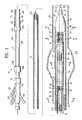
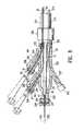
- FIG. 1is an elevational view in partial longitudinal section illustrating an embodiment of a delivery system for an expandable intracorporeal device having features of the invention.
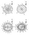
- FIG. 2is a transverse cross sectional view of the delivery system of FIG. 1 taken along lines 2 — 2 of FIG. 1 .
- FIG. 3is a transverse cross sectional view of the delivery system of FIG. 1 taken along lines 3 — 3 of FIG. 1 .
- FIG. 4is a transverse cross sectional view of the delivery system of FIG. 1 taken along lines 4 — 4 of FIG. 1 .
- FIG. 5is a transverse cross sectional view of the delivery system of FIG. 1 taken along lines 5 — 5 of FIG. 1 .
- FIG. 6Ais an enlarged elevational view in partial section of the delivery system in FIG. 1 .
- FIG. 6Bis an enlarged elevational view in partial section of the delivery system of FIG. 1 with portions of the graft and self-expanding members cut away for clarity of view of the belt bushings.
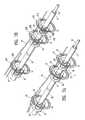
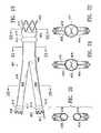
- FIG. 7Ais a perspective view showing release belt configurations having features of the invention.
- FIG. 7Bis a perspective view showing an alternative embodiment of release belts.
- FIG. 7Cis an end view showing an alternative embodiment of release belts.
- FIG. 7Dis a perspective view of the embodiment of FIG. 7 C.
- FIG. 7Eis an enlarged view of a particular coupling configuration between end loops of release belts.
- FIG. 7Fis a perspective view, partially cut away, of a particular embodiment of an end loop of a release belt.
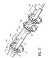
- FIG. 7Gis a perspective view of an alternative embodiment of a release belt.
- FIG. 7His a perspective view of an alternative embodiment of a release belt.
- FIG. 7Iis a perspective view of an alternative embodiment of a branched release wire.
- FIG. 7Jis an end view showing an alternative embodiment of a release belt.
- FIG. 7Kis a transverse cross sectional view showing the alternative embodiment of the release belt configuration of FIG. 7J constraining a self-expanding member.
- FIG. 7Lis a detail of the connection formed where a release wire is used with the alternative release belt embodiment of FIGS. 7J-7K.
- FIG. 8is an elevational view in partial section of the proximal adapter shown in FIG. 1 .
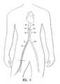
- FIG. 9is a diagrammatic view of a patient's body illustrating the patient's heart, aorta, iliac arteries, femoral arteries, and a delivery system having features of the invention disposed within the femoral artery and aorta.
- FIG. 10is a diagrammatic view of a delivery system having features of the invention disposed within an artery of a patient with an expandable intracorporeal device being deployed within the artery.
- FIG. 11is a diagrammatic view of a delivery system having features of the invention disposed within an artery of a patient with an expandable intracorporeal device being deployed within the artery.
- FIG. 12is an enlarged diagrammatic view of a delivery system having features of the invention disposed within an artery of a patient with an expandable intracorporeal device being deployed within the artery.
- FIG. 13is an elevational view in partial section of a connection between an inflation tube and an inflation port of an endovascular graft.
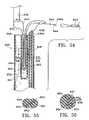
- FIG. 14is an elevational view in partial longitudinal section illustrating an embodiment of a delivery system for an expandable intracorporeal device having features of the invention.
- FIG. 15is a transverse cross sectional view of the delivery system of FIG. 14 taken along lines 15 — 15 in FIG. 14 .
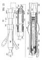
- FIG. 16is an enlarged elevational view in partial section of the delivery system shown in FIG. 14 .
- FIG. 17is an elevational view in partial section of the proximal adapter of the delivery system shown in FIG. 14 .
- FIG. 18is an elevational view in partial section of an alternative embodiment of the proximal adapter of the delivery system shown in FIG. 14 with a nested handle configuration.
- FIG. 19is an elevational view of a bifurcated stent graft suitable for delivery and deployment by embodiments of the invention.
- FIG. 20is a transverse cross sectional view of the stent graft of FIG. 19 taken along lines 20 — 20 in FIG. 19 .
- FIG. 21is a transverse cross sectional view of the stent graft of FIG. 19 taken along lines 21 — 21 of FIG. 19 .
- FIG. 22is a transverse cross sectional view of the stent graft of FIG. 19 taken along lines 22 — 22 of FIG. 19 .
- FIG. 23is an elevational view in partial section of an embodiment of a delivery system having features of the invention.
- FIG. 24is a transverse cross sectional view of the delivery system of FIG. 23 taken along lines 24 — 24 of FIG. 23 .
- FIG. 25is a transverse cross sectional view of the delivery system of FIG. 23 taken along lines 25 — 25 of FIG. 23 .
- FIG. 26is an elevational view in partial section showing an enlarged view of a distal portion of the delivery system of FIG. 23 .
- FIG. 27is a transverse cross sectional view of the delivery system of FIG. 26 taken along lines 27 — 27 of FIG. 26 .
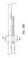
- FIG. 28is a transverse cross sectional view of the delivery system of FIG. 26 taken along lines 28 — 28 of FIG. 26 .
- FIG. 28Ais a transverse cross sectional view of an alternative embodiment of a secondary belt support member of a delivery system similar in function to that shown in FIG. 28 .
- FIG. 28Bis an elevational view of the alternative embodiment of the secondary belt support member of FIG. 28 A.
- FIG. 29is a transverse cross sectional view of the delivery system of FIG. 26 taken along lines 29 — 29 of FIG. 26 .
- FIG. 30is a transverse cross sectional view of the delivery system of FIG. 26 taken along lines 30 — 30 in FIG. 26 .
- FIG. 31is an elevational view in partial section of the proximal adapter of the delivery system of FIG. 23 .
- FIG. 32is a perspective view of the belt support member assembly at a distal portion of the delivery system of FIG. 23 .
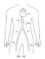
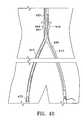
- FIG. 33illustrates a portion of the internal vasculature of a patient, including the aorta, iliac and femoral arteries branching therefrom.
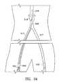
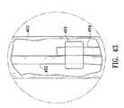
- FIG. 34is a magnified view of the abdominal aorta area of the patient shown in FIG. 33 and shows a guidewire positioned in the aorta from the right iliac artery.
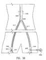
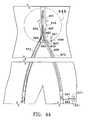
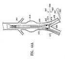
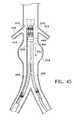
- FIGS. 35-37illustrate the magnified view of the abdominal aorta of the patient shown in FIG. 33 and depict a deployment sequence of the bifurcated endovascular stent graft of FIG. 19 with the delivery system of FIG. 23 .
- FIG. 37Ais a perspective view of a marker disposed on the delivery system distal section in the vicinity of the nosepiece.
- FIG. 37Bis a perspective view of an alternative embodiment of a marker for use in the delivery system of the present invention.
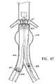
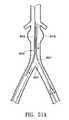
- FIGS. 38-52continue to illustrate a deployment sequence of the bifurcated endovascular stent graft of FIG. 19 .
- FIGS. 53-57illustrate a number of alternative catheter distal shaft arrangements in which a well is provided to facilitate the orderly and tangle-free withdrawal of the release strand from the delivery catheter.
- FIGS. 1-8 and 10illustrate an embodiment of delivery system 10 for delivering a variety of expandable intracorporeal devices; specifically, an expandable endovascular graft 11 .
- an expandable endovascular graft 11useful for delivery and deployment at a desired site within a patient is disclosed in co-pending U.S. patent application Ser. No. 09/133,978, filed Aug. 14, 1998, by M. Chobotov, which is hereby incorporated by reference in its entirety.
- Delivery system 10 in FIG. 1has an elongate shaft 12 with a proximal section 13 , a distal section 14 , a proximal end 15 and a distal end 16 .
- the distal section 14has an elongate belt support member in the form of a guidewire tube 17 disposed adjacent a portion of the expandable endovascular graft 11 .
- a guidewire 18is disposed within guidewire tube 17 .
- a plurality of belts 21 , 22 , and 23are secured to the guidewire tube 17 and are circumferentially disposed about portions of the endovascular graft 11 .
- FIG. 1shows the belts in a configuration that constrains the endovascular graft 11 .
- First and second release members 24 and 25(such as release wires) releasably secure belts 21 , 22 , and 23 in a constraining configuration as shown.
- the endovascular graft 11has a proximal end 26 , a distal end 27 , a proximal inflatable cuff 28 , a distal inflatable cuff 30 , a proximal self-expanding member 31 , a first distal self-expanding member 32 and a second distal self-expanding member 33 .
- the proximal end of the elongate shaftis the end 15 proximal to an operator of the delivery system during use.
- the distal end of the elongate shaftis the end 16 that enters and extends into the patient's body.
- proximal and distal directions for the delivery system 10 and endovascular graft 11 loaded within the delivery system 10 as used hereinare the same.
- This conventionis used throughout the specification for the purposes of clarity, although other conventions are commonly used.
- another useful conventiondefines the proximal end of an endovascular graft as that end of the graft that is proximal to the source of blood flow going into the graft.
- Such a conventionis used in the previously discussed co-pending patent application Ser. No. 09/133,978, although that convention is not adopted herein.
- the guidewire tube 17has an inner lumen 34 , as shown in FIG. 2, a distal section 35 , a proximal end 36 , as shown in FIG. 8, and a distal end 37 .
- the inner lumen 34 of the guidewire tube 17terminates at the distal end 37 with a distal guidewire tube port 38 , as shown in FIG. 10 .
- the proximal end 36 of guidewire tube 17terminates in a port 41 disposed in the proximal adapter 42 .
- the port 41is typically a tapered fitting such as a Luer lock fitting which facilitates the attachment of a hemostasis valve (not shown).
- the guidewire tube 17is a hollow tubular member that normally has an annular cross section, although oval cross-sectional profiles and others are also suitable.
- Distal nose piece 44is configured in a streamlined bullet shape for easy passage within a patient lumen or vessel such as aorta 45 .
- Guidewire tube 1 7may be bonded to the inner lumen 43 of the nose piece 44 , or it may be molded into the nose piece 44 during manufacture.
- the nose piece 44has a distal portion 46 , an intermediate portion 47 and a proximal shoulder portion 48 configured to slidingly engage the distal portion 51 of an inner lumen 52 of an outer tubular member 53 .
- a first distal belt 21is secured to the guidewire tube 17 .
- the first distal beltmay be secured to the guidewire tube 17 with any suitable adhesive such as cyanoacrylate, epoxy or the like. Both free ends 55 and 56 of the first distal belt 21 are secured to the guidewire tube 17 .
- the guidewire tube 17may be made from a variety of suitable materials including polyethylene, teflon, polyimide and the like.
- the inner lumen 34 of the guidewire tube 17has an inside diameter that can accommodate a guidewire suitable for guiding a device such as delivery system 10 .
- the inner lumen 34 of the guidewire tube 17may have an inside diameter of about 0.015 inch to about 0.045 inch; specifically, about 0.020 inch to about 0.040 inch.
- the outer diameter of the guidewire tube 17may range from about 0.020 inch to about 0.060 inch; specifically, about 0.025 inch to about 0.045 inch.
- an optional first distal belt bushing 57is disposed about the guidewire tube 17 so as to cover the portions of the free ends 55 and 56 of the first distal belt 21 that are secured to the distal section 35 of the guidewire tube 17 .
- This bushing 57may also serve to control the constrained configuration of the belted self-expanding members, and may include geometric features to engage or support the belted members.
- a similar configurationis present at a second distal belt 22 which has free ends secured to the guidewire tube 17 proximal to the first distal belt 21 .
- a second distal belt bushing 63is disposed about the guidewire tube 17 so as to cover the portions of the free ends of the second distal belt 22 that are secured to the guidewire tube 17 .
- a proximal belt 23has free ends secured to the guidewire tube 17 proximal to the second distal belt 22 and has an optional proximal belt bushing 67 , as shown in FIG. 6B, configured similarly to the first and second distal belt bushings 57 and 63 .
- the belts 21 , 22 and 23can be made from any high strength, resilient material that can accommodate the tensile requirements of the belt members and remain flexible after being set in a constraining configuration.
- belts 21 , 22 and 23are made from solid ribbon or wire of a shape memory alloy such as nickel titanium or the like, although other metallic or polymeric materials are possible.
- Belts 21 , 22 and 23may also be made of braided metal filaments or braided or solid filaments of high strength synthetic fibers such as Dacron®, Spectra or the like.
- An outside transverse cross section of the belts 21 , 22 and 23may range from about 0.002 to about 0.012 inch, specifically, about 0.004 to about 0.007 inch.
- the cross sections of belts 21 , 22 and 23may generally take on any shape, including rectangular (in the case of a ribbon), circular, elliptical, square, etc.
- a ratio of a cross sectional area of the belts to a cross sectional area of the release members, 24 and 25of about 1:2 is useful to balance the relative strength and stiffness requirements.
- Other ratios, however,may also be used depending on the desired performance characteristics.
- the inner diameters of belt bushings 57 , 63 and 67are sized to have a close fit over the guidewire tube 17 and secured portion 71 , as shown in FIG. 7A, of the free ends of the belts 21 , 22 and 23 that are secured to the guidewire tube 17 .
- the inner diameter of the belt bushings 57 , 63 and 67range from about 0.025 inch to about 0.065 inch; specifically, about 0.030 inch to about 0.050 inch.
- the outer diameter of belt bushing 57may be sized to approximate an inner diameter 70 , as shown in FIG. 4, of the respective first distal self-expanding member 32 of the endovascular graft 11 when the member 32 is in a fully constrained state.
- the other belt bushings 63 and 67may be similarly configured with respect to the second distal self-expanding member 33 and the proximal self-expanding member 31 .
- the outer diameter of the belt bushings 57 , 63 and 67may range from about 0.040 inch to about 0.200 inch; specifically, about 0.060 inch to about 0.090 inch.
- the material of the belt bushings 57 , 63 and 67may be any suitable polymer, metal, alloy or the like that is bondable.
- the belt bushings 57 , 63 and 67are made from a polymer such as polyurethane, silicone rubber or PVC plastic.
- belts 21 , 22 and 23extend radially from the guidewire tube 17 through optional standoff tubes 72 , 73 and 74 .
- Standoff tubes 72 , 73 and 74are disposed about belts 21 - 23 adjacent the guidewire tube 17 and act to prevent separation of belts 21 - 23 in a circumferential direction as tension is applied to the belts.
- Standoff tubes 72 - 74also prevent belts 21 - 23 from applying other undesirable forces on portions of the endovascular graft 11 that are constrained by the belts.
- the standoff tubes 72 - 74prevent the belts 21 - 23 from spreading the self-expanding members 31 - 33 , or portions thereof, at those locations where the belts 21 - 23 extend radially through the self-expanding members.
- the standoff tubes 72 - 74typically have a length substantially equal to a single wall thickness of the self-expanding members 31 , 32 and 33 .
- the length of the standoff tubes 72 - 74may range from about 0.010 inch to about 0.030 inch.
- An inner diameter of an inner lumen 75 of the standoff tubes, as shown in FIG. 4,may range from about 0.004 to about 0.024 inch, with a wall thickness of the standoff tubes being about 0.002 inch to about 0.006 inch.
- the standoff tubes 72 - 74are made from a high strength metal or alloy such as stainless steel, although they may be polymeric as well.
- Belts 21 - 23exit the outer apertures of standoff tubes 72 - 74 and extend circumferentially about the respective portions of the expandable intracorporeal device 11 .
- the term “circumferential extension” as used with regard to extension of the belts 21 - 23is meant to encompass any extension of a belt in a circumferential direction.
- the beltsmay extend circumferentially a full 360 degrees, or any portion thereof.
- belts or belt segmentsmay extend partially about an endovascular device, and may be combined with other belts or belt segments that also partially extend circumferentially about an endovascular device.
- a plane formed by each of the belts 21 - 23 when in a constraining configurationis generally perpendicular to a longitudinal axis 76 , shown in FIG.
- loop ends 81 , 82 and 83 of the belts 21 , 22 and 23are releasably locked together by one or more release members.
- a release member in the form of a first release wire 24is shown disposed within end loops 81 of the first distal belt 21 and end loops 82 of the second distal belt 22 so as to secure the first and second distal belts 21 and 22 in a constraining configuration about the endovascular graft 11 .
- Another release member in the form of a second release wire 25is shown disposed within end loops 83 of the proximal belt 23 so as to secure the proximal belt 23 in a constraining configuration about the endovascular graft 11 .
- a single release wiremay also be used to perform the function of each of the first and second release wires, 24 and 25 , so that first distal belt 21 , second distal belt 22 , and proximal belt 23 may be releasably secured by a single release wire.
- a highly controlled, sequential belt deployment schememay be realized with the use of a single release wire.
- the end loops of any single belttouch each other or are spaced closely together such that the belt as a whole forms a substantially circular constraint lying substantially in a plane.
- Release wire 24 and 25may be made from suitable high strength materials such as a metal or alloy (e.g., stainless steel) which can accommodate the torque force applied to the release wire by the belt end loops 83 when the belts 23 are under tension from the outward radial force of the constrained portions of the endovascular graft 11 , i.e., the self-expanding members 32 and 33 .
- the release wires 24 and 25may generally have an outer diameter ranging from about 0.006 to about 0.014 inch. Distal end portions 84 and 85 of release wires 24 and 25 , respectively, may terminate at any appropriate site distal of the end loops 81 - 83 of belts 21 - 23 . As shown in FIG. 8, the proximal ends 86 and 87 of the release wires 24 and 25 extend through the elongate shaft 12 of the delivery system 10 through proximal ports 91 and 92 on the proximal adapter 42 , respectively, and terminate at respective release wire handles 93 and 94 which are releasably secured to the proximal adapter 42 .
- FIG. 7Billustrates an alternative embodiment of the belts 21 - 23 of FIG. 7 A.
- belts 21 - 23are shown as each consisting of a single strand of wire formed into the end loops 81 - 83 , respectively, with the end loops in an overlapping configuration.
- Free ends 55 and 56 of belt 21are shown secured to the distal section 35 of the guidewire tube 17 .
- FIG. 7Bwherein like elements with regard to FIG. 7A are shown with like reference numerals, shows belts 21 B, 22 B and 23 B formed of two strands of wire, with each strand formed into a single loop which overlaps a loop of the other strand to form end loops 81 B, 82 B and 83 B.
- the free ends of the belts 21 B- 23 Bmay be secured in a similar manner to those of free ends 55 and 56 of FIG. 7 A.
- FIGS. 7C and 7Dillustrate alternative belts 21 C, 22 C and 23 C disposed on guidewire tube 17 .
- Single or multiple belts 21 C- 23 Cmay be deployed at various locations along guidewire tube 17 as desired.
- the members comprising belts 21 C- 23 Care shown as a single line.
- belts 21 C- 23 Cmay be of a single- or multiple strand or filament design with various cross-sectional shapes as previously described. A single solid ribbon or wire is particularly useful.
- Belts 21 C- 23 C shown in FIGS. 7C and 7Dare a single strand filament wrapped around guidewire tube 17 and fixed thereon via any number of suitable techniques, such as gluing with adhesive, mechanical fixation, etc. Especially useful is fixing the belt with an ultraviolet-curable adhesive.
- belts 21 C- 23 Cmay comprise two strand filaments each wrapped around guidewire tube 17 so that, for instance, belt 21 C is a two-filament component.
- Belt 21 Cincludes belt arms 112 and 114 , each of which, in the embodiments shown, is a loop of filament twisted upon itself to form a helix. Any number of twists may be imparted to arms 112 and 114 to provide a relatively loose or relatively tight helix as desired. Typically the number of twists (with a single twist being defined as a single overlap of wire segment) in each belt arm 112 and 114 numbers from zero to about 50 or more; specifically, about two to about 10. The choice of material used for belt 21 C is an important factor in determining the optimum number of twists for each belt arm. Belt arms 112 and 114 may be formed into other configurations (e.g., braid, double helix, etc.) as well.
- distal apertures or openings 120 , 122Disposed within the end loops of the belt arms 112 and 114 are distal apertures or openings 120 , 122 , respectively.
- a release wire(such as wire 24 ) is passed through each aperture 120 , 122 after the belt arms are wrapped around the graft self-expanding member, preferably in a circumferential groove as further described below.
- the release wiremay also be disposed through any aperture created along the length of belt arms 112 , 114 by each helix twist, although the distal-most apertures 120 , 122 are preferred.
- the wireoptionally may be welded, glued, or otherwise fixed to itself at discrete points or along all or any portion of belt arms 112 , 114 , save their corresponding apertures 120 and 122 .
- the belt arm wiremay be glued or welded to itself at the overlap or twist points, such as points 124 .
- FIG. 7Dshows an optional belt arm sleeve 126 that may be used to enclose a portion of one or both belt arms 112 , 114 , or any of the other belt embodiments contemplated herein.
- Belt 112is shown in FIG. 7D being constrained or covered over a length thereof by a flexible sleeve or coating 126 (or alternatively, a coil wrapping or by fixing the loop to itself by adhesives, welding, soldering, brazing, etc.).
- Sleeve or coating 126may optionally be shrink-wrapped, crimped, or otherwise configured to constrain or cover belt arm 112 therein.
- fixation and sleeve featureshelp to minimize the potential of belt arm untwisting and tend to close or block some or all of the helix apertures along the length except those through which the release wire are intended to pass. They can also provide greater structural and operational stability to the catheter system as a whole.
- Belt arm sleeve 126can be configured to have a transverse dimension that is sized to fit a twisted belt arm with fixed nodal points such as the belt arm 112 shown in FIG. 7 D. In order to accommodate such a twisted belt arm 112 , the inner diameter and outer diameter would be large relative to a transverse dimension of the wire material that forms the belt arm 112 . However, the belt arm sleeve 126 can also be only slightly larger in transverse dimension that the wire that forms the belt arm. For example, embodiments of belt arms that do not have twisted wires may have a sleeve 126 that fits closely or tightly over two strands of wire forming a belt arm.
- the sleeve 126can cover substantially the entire length of such an untwisted belt arm from at least the guidewire tube to just proximal of the distal loop, such as distal loop 120 .
- the distal loopshould remain exposed for engagement by a release wire.
- the sleeve covered portion of the belt armmay also be wrapped around and secured to the guidewire tube just as the unsleeved belt portion of the belt arm 112 shown in FIG. 7D is shown at 71 C.
- This type of low profile belt arm sleevemay also be used to cover twisted belt arm embodiments, although a slightly larger diameter sleeve would be required.
- FIG. 7C viewshows belt arms 112 , 114 symmetrically disposed at an angle ⁇ as measured from a horizontal plane 125 .
- This angle amay range from zero to 180 degrees.
- Any known techniquesmay be used to impart a desired resting configuration to the system, such as, for example, cold working or shape-setting by way of an athermal phase transformation (in the case of shape memory alloys).
- FIG. 7Jshows a single belt example of the version shown in FIGS. 7C and 7D.
- a single belt arm 113is shown disposed about the distal section 35 of guidewire tube 17 .
- Belt arm 113is significantly longer than either belt arm 112 or 114 of the FIGS. 7C-7D embodiment so that it may extend at least around the circumference of any one of self-expanding members 31 , 32 , or 33 .
- the distal portion 115 of belt arm 113meets a more proximal portion 117 where one or both strands (when the belt arm 113 is a twisted variety) extends through an end loop 119 in the belt arm 115 distal portion.
- a release membersuch as release wire 24 may be inserted through end loop 119 and the intersecting portion of the belt arm proximal portion 117 to releasably secure belt arm 113 in a constraining configuration about the endovascular graft 11 .
- FIG. 7Kdepicts a simplified schematic cross-sectional view of belt arm 113 (shown here untwisted) held in place by a release wire 24 about an exemplary self-expanding member 32 .
- FIG. 7Lis a detail of the connection formed where release wire 24 intersects the distal and proximal portions, 115 and 117 , respectively, of belt arm 113 .
- FIGS. 7C-7D embodimentmay be employed in the embodiment of FIGS. 7J-7K as well.
- This helix configuration shown in the embodiments of FIGS. 7C-7D and 7 J- 7 Lis a particularly reliable configuration. It reduces the possibility that a portion of belt 21 C becomes entangled with a self-expanding member (such as members 31 , 32 and 33 ) or otherwise interferes with the safe and effective deployment of the prosthesis.
- a self-expanding membersuch as members 31 , 32 and 33
- FIG. 7Edepicts a particularly useful arrangement for configuring the belt end loops 81 - 83 with release wires 24 - 25 during assembly of delivery system 10 .
- first and second end loops 81 ′ and 81 ′′ of belt 21are shown connected via release wire 24 .
- first end loop 81 ′is passed through aperture 88 disposed in second end loop 81 ′′.
- a portion of aperture 89 disposed in first end loop 81 ′should extend through the plane created by second end loop 81 ′′ as shown in FIG. 7 E.
- release wire 24is passed through the portion of aperture 89 that extends beyond this plane so that wire 24 “locks” the two looped ends 81 ′ and 81 ′′ together as shown.
- Thisis a stable configuration that lends itself well to a reliable and safe deployment protocol.
- Wire 24may simply pass through loop ends as configured and as shown at reference numerals 81 , 82 and 83 in FIG. 7A, and 81 B, 82 B and 83 B of FIG. 7B as well.
- belt 110is a member in the shape of a wire formed into an end loop 116 B having an aperture 120 for receiving a release wire.
- This arrangementmay be used on one or both ends of belt 110 or, alone if belt 110 is in the form of a single belt arm as discussed above.
- Connection 122is shown in FIG. 7F as a simple wrapping of the distal end 116 A of the wire comprising belt 110 .
- Connection 122need not be limited to such a tapered or cylindrical sleeve or coating, however.
- Other methods to form end loop 116 Bare contemplated, including, for example, the use of adhesives, welding, brazing, soldering, crimping, etc.
- An optional protective sleeve or coating 127covers or is part of connection 122 and serves to protect the patient as well as components of the delivery system and prosthesis from damage.
- FIGS. 7G and 7Htwo alternative embodiments of a ribbon-like belt 81 G and 81 H are shown.
- a section 128 of materialhas been partially displaced from belt 81 G distal end 116 C and worked into a loop-like member 129 such that two generally orthogonal apertures 130 , 132 are formed in belt distal end 116 C.
- a set of hinges or other protective mechanism or materialmay be used on each end of this section 128 so that further tearing or peeling of this member may be prevented.
- Section 128may be formed integrally from the belt distal end 116 C as shown in FIG. 7G or may be a separate component that is attached to the belt distal end by any suitable means.
- Second belt distal end 118 C in FIG. 7Gis shown as having an aperture 133 disposed therein.
- a half-twistis imparted to the ribbon-like belt 81 G as the second distal end 118 C is brought through aperture 130 such that apertures 132 and 133 are at least partially aligned.
- a release wire(such as wire 24 ) is then brought through apertures 132 and 133 to releasably join ends 116 C and 118 C.
- FIG. 7Hshows yet another embodiment of a belt 81 H where a simple rectangular aperture 133 A is disposed in the distal end 117 of belt 81 H through which another belt end and release wire may be disposed as taught herein.
- a half-twistis imparted to the belt 81 H in use so that the second distal end 118 D is brought through aperture 133 .
- a release wiremay then be threaded through apertures 132 and 133 to releasably join ends 117 and 118 D.
- aperture 132should be large enough to accommodate both second distal end 11 8 D and a release wire.
- FIG. 7Ishows a perspective view of a belt assembly similar to that shown in FIG. 7A, wherein like elements are shown with like reference numerals.
- An alternative embodiment of a release wire consisting of a branched release wire 150is illustrated in FIG. 7 I.
- the branched release wire 150engages belts 21 - 23 and is configured to release belts 21 - 23 at different times with a proximal withdrawal movement of the branched release wire 150 , the direction of which is indicated by arrow 151 .
- Branched release wire 150has a main portion 152 and a branch portion 153 . Branch portion 153 is secured to main portion 152 by a solder joint 154 .
- the joint 154could also be made by any other suitable means, such as welding, bonding with an epoxy, mechanically binding the joint, or the like.
- the embodiment of the branched release wire shown in FIG. 71consists of wire which is generally round in cross section.
- the wire of the branched release wirecan have the same or similar material and mechanical properties to the wire of the release wires 24 and 25 discussed above.
- Branch portion 153engages first distal belt 21 and second distal belt 22 .
- a distal segment 155has a length L indicated by arrow 156 which extends distally from first distal belt 21 to the distal end 157 of branch portion 153 .
- Main portion 152 of the branched release wire 150engages the proximal belt 23 and has a distal segment 158 that extends distally from the proximal belt 23 to a distal end 161 of the main portion.
- the length L′ of the distal segment 158 of the main portion 152is indicated by arrow 162 .
- Length L of distal segment 155is greater than length L′ of distal segment 158 .
- Such a branched release wireallows a wide variety of belt release timing with a single continuous withdrawal or movement of a proximal end (not shown) of the branched release wire 150 .
- the proximal end of the branched release wiremay be terminated and secured to a release wire handle or the like, as discussed herein with regard to other embodiments of release wires.
- the ability to deploy multiple release wires in a desired timing sequence with a single branched release wire 150gives the designer of the delivery system great flexibility and control over the deployment sequence while making the deployment of the belts simple and reliable for the operator of the delivery system.
- branched release wire 150has been shown with only a single branch, any number of branches or desired configuration could be used to achieve the deployment sequence required for a given embodiment of a delivery system.
- a separate branchcould be used for each belt in a multiple belt system, with varying distal segment length used to control the sequence of deployment.
- multiple branched release wires, or the likecould be used in a single delivery system to achieve the desired results.
- a number of embodiments for the belt and belt arm components of the present inventionare described herein. In general, however, we contemplate any belt or belt arm configuration in which the belt may be used to releasably hold or restrain an implant member in conjunction with a release member.
- the particular embodiments disclosed hereinare not meant to be limiting, and other variations not explicitly disclosed herein, such as those in which multiple apertures (which may have varying shapes and sizes) are disposed along the belt length, those in which the belt or belt arm distal ends comprises a separate material or element that is affixed to the belt or belt arm, etc. are within the scope of the invention.
- various embodiments of the ends of the belts or belt arms taught hereinmay exist in any combination in a single delivery system.
- belts 21 - 23lie within circumferential grooves or channels 95 , 96 and 97 , respectively, formed into the respective self-expanding members 31 , 32 and 33 .
- Grooves 95 - 97prevent axial displacement of the belts 21 - 23 prior to activation or release of the releasable members 24 and 25 , i.e., proximal retraction of the first and second release wires.
- grooves 95 - 97are illustrated in the embodiment shown, other alternatives are possible to achieve the same or similar function of the grooves.
- abutments extending slightly from the self-expanding members 31 - 33 on either side of the belts 21 - 23 in their constraining configurationcould prevent axial movement of the belts.
- a detachable adhesive or the likecould also be used.
- the release of end loops 81 - 83occurs when the distal end portions 84 and 85 of the release wires 24 and 25 , respectively, pass from within the overlapped end loops 81 - 83 . If the end loops 81 - 83 move axially in response to movement of the release wires 24 and 25 due to frictional forces imposed on the end loops 81 - 83 by the release wires, the point at which the distal end portions 84 and 85 pass from within the end loops 81 - 83 would vary depending on the amount of movement of the end loops 81 - 83 .
- the timing of the release of the belts 21 - 23could be adversely affected.
- the prevention of axial displacement of the belts 21 - 23 during proximal retraction of the release wires 24 and 25facilitates accurate release of the belts by keeping the overlap joint of the belt looped end portions in a constant axial position during such retraction.
- belts 21 - 23may be desirable to keep belts 21 - 23 positioned at or near the general center of a given constrained self-expanding members 31 - 33 so that the self-expanding member 31 - 33 is substantially uniformly and evenly constrained over its axial length. If belts 21 - 23 constrain the self-expanding members 31 - 33 at a non-centered axial position on the member, an end of the member opposite that of the non-centered position may be less constrained and may interfere with axial movement of the outer tubular member 53 (and consequently deployment of the endovascular graft 11 ).
- Tubular body member 205 of the endovascular graft 11is disposed between and secured to the second distal self-expanding member 33 and the proximal self-expanding member 31 .
- the tubular body member comprised of flexible material 204is shown constrained in an idealized view in FIGS. 1, 3 and 6 , for clarity. In practice, tubular body member 205 while constrained is tightly compressed with minimal air space between layers of flexible material 204 so as to form a tightly packed configuration as shown in FIG. 3 .
- Tubular body member 205is optionally radially constrained by an inside surface 206 of the inner lumen 52 of outer tubular member 53 .
- An inner tubular member 207is slidably disposed within the inner lumen 52 of outer tubular member 53 .
- Release wires 24 and 25 , guidewire tube 17 and an inflation tube 211are disposed within an inner lumen 212 of the inner tubular member 207 .
- Inner lumen 212is optionally sealed with a sealing compound, depicted in FIGS. 1, 2 and 6 A by reference numeral 213 at distal end 214 .
- the sealing compound 213prevents leakage of fluids such as blood, etc., from a proximal end 215 , shown in FIG. 8, of the inner tubular member 207 .
- Sealing compound 213fills the space within the inner lumen 212 of the inner tubular member 207 between an outer surface 216 of the guidewire tube 17 , the outer surface 217 of the inflation tube 211 and outer surfaces 221 and 222 of a tubular guide 223 for the first release wire 24 and a tubular guide 224 for the second release wire 25 .
- the sealing compound 213can be any suitable material, including epoxies, silicone sealer, ultraviolet cured polymers, or the like.
- tubular guides 223 and 224 for the first release wire 24 and the second release wire 25allow axial movement of the release wires with respect to the sealing compound 213 and inner tubular member 207 .
- the inside diameter of the inner lumens of the tubular guides 223 and 224are sized to fit closely with an outer diameter or transverse dimension of the release wires 24 and 25 .
- tubular guides 223 and 224may be replaced by a single tubular guide that houses one or more release wires, such as wires 24 and 25 .
- the inner tubular member 207terminates proximally with the proximal adapter 42 having a plurality of side arms 225 , 226 and 227 and a proximal exit port 231 for the inner lumen 34 of the guidewire tube 17 .
- First release wire side arm 225branches from a proximal adapter body portion 233 and has an inner lumen 234 and proximal end 86 of the first release wire 24 .
- a proximal extremity 236 of the first release wire 24is anchored to the first release wire proximal handle 93 which is threaded onto the proximal end 238 of the first release wire side arm 225 .
- the proximal extremity 236 of first release wire 24is configured as an expanded bushing or other abutment that captures the handle 93 and translates proximal axial movement of the handle 93 to the first release wire 24 but allows relative rotational movement between the handle 93 and the proximal end 86 of the first release wire 24 .
- a second release wire side arm 226branches from the proximal adapter body portion 233 and has an inner lumen 244 that houses the proximal end 87 of the second release wire 25 which is free to slide in an axial orientation within the lumen 244 .
- a proximal extremity 246 of the second release wire 25is configured as an expanded bushing or other abutment that captures the second release wire handle and translates axial proximal movement of the second release wire handle 94 to the second release wire 25 , but allows relative rotational movement between the proximal end 87 of the second release wire 25 and the second release wire handle 94 .
- the first release wire handle 93 and second release wire handle 94may optionally be color coded by making each, or at least two, release wire handles a color that is distinctly different from the other.
- the first release wire handle 93could be made green in color with the second release wire handle 94 being red in color. This configuration allows the operator to quickly distinguish between the two release wire handles and facilitates deployment of the belts in the desired order.
- the spatial location of the handlescan be configured to convey the proper order of deployment of the release wires to the operator of the delivery system.
- the corresponding three side armscan be positioned along one side of the proximal adapter.
- the release wire handle that needs to be deployed firstcan extend from the distal-most side arm.
- the release wire handle that needs to be deployed secondcan extend from the middle side arm.
- the release wire handle that is to be deployed lastcan extend from the proximal-most side arm.
- the operatoris merely instructed to start deployment of the release wires at the distal-most release wire handle and work backward in a proximal direction to each adjacent release wire handle until all are deployed.
- an opposite or any other suitable configurationcould be adopted.
- the configurationshould adopt some type of spatially linear deployment order, either from distal to proximal or proximal to distal, in order to make reliable deployment of the release wires in the proper order easy to understand and repeat for the operator of the delivery system.
- Other types of release order indicatorssuch as those discussed above could also be used, such as numbering each release wire handle or side arm with a number that indicates the order in which that handle is to be deployed.
- the proximal end 36 of the guidewire tube 17terminates and is secured to an inner lumen 251 of the proximal end 259 of the proximal adapter 42 .
- Inner lumen 251typically has a longitudinal axis 253 that is aligned with a longitudinal axis 254 of the proximal section 13 elongate shaft 12 so as to allow a guidewire to exit the proximal end 15 of the elongate shaft 12 without undergoing bending which could create frictional resistance to axial movement of the guidewire.
- a proximal port 255 of the proximal adapter 42may be directly fitted with a hemostasis valve, or it may be fitted with a Luer lock fitting which can accept a hemostasis valve or the like (not shown).
- the proximal adapter 42may be secured to the proximal end 215 of the inner tubular member 207 by adhesive bonding or other suitable method.
- a strain relief member 256is secured to the distal end 257 of the proximal adapter 42 and the inner tubular member 207 to prevent kinking or distortion of the inner tubular member 207 at the joint.
- the proximal end 261 of the outer tubular member 53is secured to a proximal fitting 262 that slides over an outer surface 258 of the inner tubular member 207 .
- a seal 263 located in proximal fitting 262provides a fluid seal for the lumen 265 formed between the outer surface 258 of the inner tubular member 207 and the inner surface 206 of the inner lumen 52 of the outer tubular member 53 .
- the fit between the outer surface 258 of the inner tubular member 207 and the inner surface 206 of the outer tubular member 53is typically close, but still allows for easy relative axial movement between outer tubular member 53 and inner tubular member 207 .
- a stop 266is disposed and secured to the outer surface 258 of the inner tubular member 207 distal of the proximal adapter 42 to limit the amount of proximal axial movement of the outer tubular member 53 relative to the inner tubular member 207 .
- the distance between a proximal extremity 267 of proximal fitting 262 and a distal extremity of stop 266is approximately equal to or slightly greater than an axial length of the endovascular graft 11 in a constrained state.
- This configurationallows the outer tubular member 53 to be proximally retracted to fully expose the endovascular graft 11 in a constrained state prior to deployment of the graft.
- This distancemay be greater, but should not be less than the length of the endovascular graft 11 in a constrained state in order to completely free the constrained graft 11 for radial expansion and deployment.
- Retraction limitersmay alternatively be used to prevent excessive axial movement of the release wires 24 and 25 in a proximal direction during deployment. Particularly in embodiments of the invention where single release wires are used to constrain and deploy multiple belts such as with first release wire 24 , retraction limiters may be used to allow enough axial movement of the release wire 24 to deploy a first belt 21 , but prevent deployment of a second more proximally located belt 22 . For example, as shown in FIG.
- a retraction limiter in the form of a filament 269could be disposed between the proximal adapter 42 and the handle 93 of the first release wire 24 such that proximal retraction of the first release wire 24 sufficient for deployment of the first distal belt 21 could be achieved, but not so much as to allow deployment of the second distal belt 22 .
- the filament 268would have to be severed or otherwise released. This type of configuration can allow more control over deployment of the endovascular graft 11 and allow deployment in stages which are sequentially controlled to prevent inadvertent deployment of a portion of the graft 11 in an undesirable location within the patient's vessels.
- the delivery system 10is advanced into a patient's arterial system 271 percutaneously as shown in FIG. 9 and positioned so that the endovascular graft 11 spans an aneurysm 272 in the patient's aorta 45 as illustrated in FIGS. 1 and 9 - 12 . It is generally desirable to have the tubular body member 205 of the graft 11 positioned below the renal arteries 273 in order to prevent significant occlusion of the renal arteries.
- the proceduretypically begins with the placement of guidewire 18 into the patient's target vessel 45 across the target location, e.g., the aneurysm 272 .
- Common percutaneous techniques known in the artmay be used for the initial placement of the guidewire 18 . For example, as shown in FIG.
- percutaneous access to the aortamay be had through the femoral or iliac artery, although other access sites may be used.
- the delivery system 10may then be advanced over the guidewire 18 to a desired position within the patient's vessel 45 .
- delivery system 10 and guidewire 18could be advanced together into the patient's vasculature 271 with the guidewire 18 extending distally from the distal port 38 of the guidewire tube 17 .
- the position of the delivery system 10is determined using fluoroscopic imaging or the like.
- markersmay be placed longitudinally coextensive with the respective distal and proximal extremities 274 and 275 , as shown in FIG. 11 .
- Imaging markerssuch as radiopaque markers, may also be secured to desirable positions on the endovascular graft 11 itself.
- Other types of imaging and marking systemsmay be used such as computed tomography (CT), magnetic resonance imaging (MRI) and nuclear magnetic resonance (NMR) imaging systems and markers.
- CTcomputed tomography
- MRImagnetic resonance imaging
- NMRnuclear magnetic resonance
- the operatormoves the proximal end 261 of outer tubular member 53 in a proximal direction relative to inner tubular member 207 .
- the relative axial movementis carried out by grasping the proximal end 215 of the inner tubular member 207 or proximal adapter 42 , and grasping the proximal end 261 of the outer tubular member 53 , and moving the respective proximal ends towards each other.
- Thisretracts the distal section 276 of the outer tubular member 53 from the constrained endovascular graft 11 and frees the graft for outward radial expansion and deployment.
- the operatoris free to reinsert graft 11 back into the outer tubular member 53 if necessary, as the release bands have not yet released the graft.
- handle 93 of the first release wire 24may then be unscrewed or otherwise freed from the proximal adapter 42 and retracted in a proximal direction indicated by arrow 279 in FIG. 10 until the distal end 84 of the first release wire 24 passes from within the end loops 81 of the first distal belt 21 .
- the looped ends 81 of the first distal belt 21are released and the first distal belt 21 ceases to radially constrain the first distal self-expanding member 32 which thereafter self-expands in a radial direction into an inner surface 278 of the patient's aorta 45 as shown in FIG. 10 .
- the operator of the delivery system 10is not satisfied with the position, particularly the axial position, of the endovascular graft 11 after deployment of the first distal self-expanding member 32 , it may then be possible to re-position the endovascular graft 11 by manipulating the proximal end 15 of the elongate shaft 15 . Movement of the elongate shaft 12 can move the endovascular graft 11 , even though physical contact between the expanded member 32 and the vessel inner surface 278 generates some static frictional forces that resist such movement. It has been found that the endovascular graft 11 can be safely moved within a blood vessel 45 even in the state of partial deployment discussed above, if necessary.
- the first release wire 24may then be further proximally retracted so as to deploy the second distal belt 22 in a manner similar to the deployment of the first distal belt 21 .
- the deployment of the second distal belt 22occurs when the distal end 84 of the first release wire 24 passes from within end loops 82 of the second distal belt 22 which are held in a radially constraining configuration by the first release wire 24 .
- the second distal self-expanding member 33expands in a radial direction such that it may engage inner surface 278 of the patient's aorta 45 .
- the amount of outward radial force exerted by the self-expanding members 32 and 33 on the inside surface 278 of the patient's aorta 45is dependent upon a number of parameters such as the thickness of the material which comprises the self-expanding members 32 and 33 , the nominal diameter which the self-expanding members 32 and 33 would assume in a free unconstrained state with no inward radial force applied, material properties of the members and other factors as well.
- the handle 94 for the second release wire 25can be disengaged and axially retracted in a proximal direction from the proximal adapter 42 until the distal end 85 of the second release wire 25 passes from within the end loops 83 of the proximal belt 23 .
- the proximal self-expanding member 31is deployed and expands in an outward radial direction, such that it may engage or be in apposition with the inner surface 278 of the patient's aorta 45 as shown in FIG. 11 .
- the endovascular graft 11may be inflated with an inflation material (not shown) introduced into the proximal injection port 282 in the proximal adapter 42 , through the inflation tube 211 , and into the inflation port 283 of the endovascular graft 11 .
- Inflation materialmay be injected or introduced into the inflation port 283 until the proximal and distal inflatable cuffs 28 and 30 and inflatable channels 284 of the graft 11 have been filled to a sufficient level to meet sealing and other structural requirements necessary for the tubular body to meet clinical performance criteria.
- the endovascular graft 11Before or during the deployment process, and preferably prior to or simultaneous with the step of inflating the endovascular graft 11 , it may be beneficial to optionally treat vessel 45 in which the graft 11 is deployed so to obtain a better seal between the graft 11 and the vessel inner surface 278 , thus improving the clinical result and helping to ensure a long term cure.
- One approach to this treatmentis to administer a vasodilator, or spasmolytic, to the patient prior to deploying graft 11 .
- Thishas the effect of reducing the tone of the smooth muscle tissue in the patient's arteries; specifically, the smooth muscle tissue in the wall of vessel 45 into which graft 11 is to be deployed.
- tone reductionin turn induces the dilation of vessel 45 , reducing the patient's blood pressure.
- vasoactive antagonistsincluding the direct acting organic nitrates (e.g., nitroglycerin, isosorbide dinitrate, nitroprusside), calcium channel blocking agents (e.g., nifedipine), angiotensin-converting enzyme inhibitors (e.g., captopril), alpha-adrenergic blockers (e.g., phenoxybenzamine, phentolamine, prasozin), beta-adrenergic blockers (e.g., esmolol) and other drugs may be used as appropriate.
- Particularly usefulare those vasodilators that can be administered intravenously and that do not have unacceptable contraindications such as aoritic aneurysm dissection, tachycardia, arrhythmia, etc.
- the degree of vasodilatation and hypotensive effectwill depend in part on the particular vessel in which graft 11 is to be placed and the amount of smooth muscle cell content. Generally, the smaller the vessel, the larger percentage of smooth muscle cell present and thus the larger effect the vasodilator will have in dilating the vessel. Other factors that will effect the degree of vasodilatation is the health of the patient; in particular, the condition of the vessel 11 into which graft 11 is to be placed.
- graft 11may be deployed and filled with inflation material so that graft 11 reaches a larger diameter than would otherwise be possible if such a vasodilator was not used. This allows the inflation material to expand the diameter of graft 11 , for a given inflation pressure, beyond that which would be achievable if the vessel 45 were in a non-dilated state (and nominal diameter). Alternatively, a larger diameter graft 11 may be chosen for deployment. We anticipate that an increased vessel diameter of between two and twenty percent during vasodilatation may be optimal for-achieving an improved seal.
- the vessel 45 in which graft 11 is to be placedmay optionally be monitored pre- and/or post-dilation but before deployment of graft 11 (via computed tomography, magnetic resonance, intravenous ultrasound, angiography, blood pressure, etc.) so to measure the degree of vasodilatation or simply to confirm that the vasodilator has acted on the vessel 45 prior to deploying graft 11 .
- the vessel 45 surrounding graft 11returns to its normal diameter.
- the resultant graft-vessel configurationnow contains an enhanced seal between graft 11 and vessel inner surface 278 and provides for reduced luminal intrusion by graft 11 , presenting an improved barrier against leakage and perigraft blood flow compared to that obtainable without the sue of vasodilators or the like.
- vasodilating techniquesmay be used with all of the embodiments of the present invention, including the tubular graft 11 as well as a bifurcated graft version of the expandable intracorporeal device of the present invention as is discussed in detail below.
- a restraining or retention devicesuch as retention wire 285 that binds the distal end 286 of the inflation tube 211 to the inflation port 283 , as shown in FIGS. 12 and 13, is activated.
- the retention wire 285is activated by pulling the proximal end of the wire in a proximal direction so as to disengage the distal ends 293 and 294 from the holes 295 and 296 . This eliminates the shear pin function of the distal ends 293 and 294 and allows the distal end 286 of the inflation tube 211 to be disengaged from the inflation port 283 .
- the release wires 24 and 25may then be fully retracted from the elongate shaft 12 in a proximal direction and the delivery system 10 retracted in a proximal direction from the deployed endovascular graft 11 .
- the unconstrained distal belts 21 - 23slip through the openings in the expanded members 31 , 32 and 33 as the delivery system 10 is retracted and are withdrawn through the inner passageway 287 of the deployed graft 11 .
- the distal nosepiece 44is also withdrawn through the inner passageway 287 of the deployed graft 11 as the delivery system 10 is withdrawn as shown in FIGS. 10-12.
- FIG. 13illustrates the junction between the distal end 286 of inflation tube 211 and inflation port 283 .
- retention wire 285extends from the inflation port 283 proximally to the proximal end 15 of delivery system 10 . In this way, an operator can disengage the distal end 286 of the inflation tube 211 from the inflation port 283 by pulling on the proximal end of retention wire 285 from a proximal end 15 of delivery system 10 .
- the retention wire 285can be a small diameter wire made from a material such as a polymer, stainless steel, nickel titanium, or other alloy or metal; in a particular embodiment of the invention, retention wire 285 may be a spring formed of a variety of suitable spring materials. Alternatively retention wire 285 may have a braided or stranded configuration.
- FIG. 13shows a single retention filament or wire 285 disposed within the lumen 291 of the inflation tube 211 .
- the distal end 292 of retention wire 285may have one or more loops 293 and 294 , respectively, disposed within one or more side holes disposed in the inflation port 283 of the distal end 286 of the inflation tube 211 .
- a number of side hole configurationsmay be utilized.
- the embodiment of FIG. 13has two sets of opposed side hole locations 295 and 296 .
- the distal end loops 293 and 294 of the retention wire 285act to interlock the side holes 295 and 296 by creating a removable shear pin element which prevents relative axial movement between the distal end 286 of the inflation tube 211 and the inflation port 283 .
- Alternate embodimentsmay include multiple retention filaments or wires disposed within the lumen 291 of the inflation tube 211 .
- An external sleeve(not shown) may be added over this assembly to further secure the interface and prevent leakage of inflation material through side holes 295 and 296 . This sleeve is attached to inflation tube 211 and is received with it.
- FIGS. 14-17illustrate an alternative embodiment of the delivery system shown in FIG. 1 .
- the delivery system 300has an outer tubular member 53 and inner tubular member 207 at a distal section 303 of the delivery system 300 .
- An endovascular graft 11is disposed within the outer tubular member in the distal section 303 .
- An inflation tube 305similar to that of the embodiment shown in FIG. 1 is coupled to an inflation port 283 of the endovascular graft 11 .
- the inflation tube 305having a proximal end 307 and a distal end 308 , does not extend the majority of the length of the delivery system 300 . Instead, the proximal end 307 of the inflation tube 305 terminates at a proximal end 311 of the potted section 213 as shown in FIGS. 14-16.
- first release wire 312 having distal end 313engages end loops 82 of second distal belt 22 .
- the second distal belt 22is disposed about and constrains the second distal self-expanding member 33 .
- a second release wire 316 having a distal end 317engages the end loops 81 of the first distal belt 21 and the end loops 83 of the proximal belt 23 .
- the first distal belt 21is disposed about and constrains the first distal self-expanding member 32 .
- the proximal belt 23is disposed about and constrains the proximal self-expanding member 31
- a release wire tube 318having a proximal end 321 , as shown in FIG.
- the release wire tube 318has a lumen 319 , as shown in FIG. 15, that contains the first release wire 312 and the second release wire 316 .
- the proximal adapter 323has a first side arm 324 with an inner lumen 325 that secures the proximal end 321 of the release wire tube 318 .
- a threaded end cap 326is secured to a proximal end 327 of the first side arm 324 and has a threaded portion 328 .
- a second release wire handle 331having a distal threaded portion 332 and a proximal threaded portion 333 , is threaded onto the threaded end cap 326 .
- a proximal end 334 of the second release wire 316is secured to the second release wire handle 331 .
- a first release wire handle 335has a threaded portion 336 which is releasably threaded onto the proximal threaded portion 333 of the second release wire handle 331 .
- a proximal end 337 of the first release wire 312is secured to the first release wire handle 335 .
- belts 21 - 23can be released.
- This configurationallows the operator of the delivery system 300 to first disengage and proximally retract the first release wire handle 335 so as to first release the second distal self-expanding member 33 without releasing or otherwise disturbing the constrained state of the first distal self-expanding member 32 or the proximal self-expanding member 31 .
- the endovascular graft 11may be axially moved or repositioned to allow the operator to adjust the position of the graft 11 for final deployment.
- a self-expanding membersuch as self-expanding member 32 is radiopaque and the delivery procedure is performed using fluoroscopic imaging, adjustment of the position of the graft after release of self-expanding member is readily achievable.
- self-expanding member 32is immediately adjacent the distal end of the tubular body portion 205 of the graft 11 , the ability to visualize and reposition the self-expanding member 32 is particularly useful in order to position the distal end of the tubular body portion 205 just below the renal arteries without occluding the renal arteries, if such positioning is indicated for the patient being treated.
- the second release wire handle 331may be unscrewed or otherwise released from the threaded cap 326 and proximally retracted so as to first release the first distal belt end loops 81 and then the proximal belt end loops 83 .
- the position of the graft 11may still be adjustable even with both distal self-expanding members 32 and 33 deployed, depending on the particular configuration of the graft 11 and the self-expanding members 32 and 33 .
- the release of the belts 21 , 22 and 23is the same or similar to that of the belts of the embodiment of FIG. 1 and occurs when the distal end of the release wires 312 and 316 which lock the end loops 81 - 83 together is proximally retracted past the end loops 81 - 83 of the belts 21 - 23 which are constrained.
- the graft 11can then be inflated by injection of an inflation material (not shown) into the injection port 338 on a second side arm 341 of the proximal adapter 323 .
- the inflation materialis introduced or injected directly into an inner lumen 212 of the inner tubular member 207 , as shown in FIG. 17, and travels distally between an inside surface 342 of the inner tubular member 207 , outside surface 343 of the release wire tube 318 and outside surface 216 of the guidewire tube 17 .
- This cross sectional areais large relative to the cross sectional area of the inner lumen of the inflation tube 211 of the embodiment of FIG. 1 . This results in more rapid flow of inflation material to the inflatable cuffs 28 and 30 and channels 284 of the endovascular graft 11 and decreases inflation time.
- the inflation materialwhich is travelling distally in the delivery system 300 during inflation, reaches the potted portion 213 of the distal section 303 of the delivery system, it then enters and flows through a lumen 344 , as shown in FIG. 16, at the proximal end 307 of the inflation tube 305 and into the inflation port 283 of the graft 11 .
- a release devicesuch as retention wire 285 can be retracted or otherwise activated so as to de-couple the inflation tube 305 from the inflation port 283 of the endovascular graft 11 .
- a proximal end 36 of the guidewire tube 17is secured within a central arm 345 of the proximal adapter 323 which has a potted section 346 .
- a seal 349is disposed on a proximal end 347 of the central arm 345 for sealing around the guidewire 18 and preventing a backflow of blood around the guidewire.
- a hemostasis adapter(not shown) can be coupled to the proximal end 347 of the central arm 345 in order to introduce fluids through the guidewire tube lumen 348 , as shown in FIG. 15, around an outside surface of the guidewire 18 .
- the potted section 346 of the central arm 345prevents any injected fluids from passing into the inflation material lumen 351 within the proximal adapter 323 or the inner tubular member 207 .
- FIG. 18illustrates an alternative embodiment to the proximal adapters 42 and 323 used in the embodiments of the invention of FIG. 1 and FIG. 14 .
- the proximal adapter 360has a first release wire handle 361 and a second release wire handle 362 which are in a nested configuration.
- the proximal end 334 of the second release wire 316is secured to the second release wire handle 362 .
- the proximal end 337 of the first release wire 312is secured to the first release wire handle 361 .
- This configurationprevents the operator from inadvertently deploying or activating the second release wire 316 prior to deployment or activation of the first release wire 312 which could result in an undesirable endovascular graft deployment sequence.
- the operatorfirst unscrews or otherwise detaches a threaded portion 363 of the first release wire handle 361 from an outer threaded portion 364 of a first side arm end cap 365 of a first side arm 366 .
- the first release wire handle 361is then proximally retracted which releases the end loops 82 of the second distal belt 22 as discussed above with regard to the embodiment of the invention shown in FIG. 14 .
- the second release wire handle 362is exposed and accessible to the operator of the delivery system.
- a threaded portion 367 of the second release wire handle 362can then be unscrewed or otherwise detached from an inner threaded portion 368 of the first side arm end cap 365 .
- the second release wire handle 362can then be retracted proximally so as to sequentially deploy the first distal belt 21 and self-expanding member 32 and proximal belt 23 and proximal self-expanding member 31 , respectively.
- the other functions and features of the proximal adapter 360can be the same or similar to those of the proximal adapters 42 and 323 shown in FIG. 1 and FIG. 17 and discussed above.
- this embodimentmay comprise reverse or oppositely threaded portions, 363 and 367 respectively, of the first and second release wire handles 361 and 362 .
- a counter-clockwise motionmay be required to unthread threaded portion 363 of the first release wire handle 361 from the outer threaded portion 364
- a clockwise motionis in contrast required to unthread threaded portion 367 of the second release wire handle 367 from the inner threaded portion 368 .
- This featureserves as a check on the overzealous operator who might otherwise prematurely unscrew or detach the threaded portion 367 of the second release wire handle 362 by unscrewing in the same direction as required to release the threaded portion 363 of the first release wire handle 361 .
- a delivery system 400 for delivery and deployment of a bifurcated intracorporeal devicespecifically, an embodiment of the invention directed to delivery and deployment of a bifurcated endovascular graft or stent is contemplated.
- the delivery system 400 for a bifurcated deviceis configured for delivery and deployment a wide variety of intracorporeal devices.
- embodiments of the delivery systems disclosed hereincan are also suitable for delivery of intravascular filters, stents, including coronary stents, other types of shunts for intracorporeal channels, aneurysm or vessel occluding devices and the like.
- the structure, materials and dimensions of the delivery system 400 for bifurcated devicescan be the same or similar to the structure, materials and dimensions of the delivery systems discussed above.
- the structure, materials and dimensions of bifurcated grafts contemplated hereincan have structure, materials and dimensions similar to those of grafts having a primarily tubular shape discussed above.
- FIGS. 19-22illustrate an embodiment of an expandable intracorporeal device in the form of a bifurcated stent-graft 401 .
- This embodimentincludes a main body portion 402 at a distal end 403 of the graft 401 that has a generally tubular cross-sectional profile when the graft takes on an expanded or deployed configuration.
- An ipsilateral leg 404 and contralateral leg 405(short leg), both having a substantially tubular configuration when expanded or deployed, branch from the main body portion 402 at bifurcation 406 and extend in a proximal direction from the bifurcation 406 .
- the ipsilateral leg 404terminates proximally with a proximal self-expanding member 407 and the contralateral leg 405 terminates proximally with a proximal self-expanding member 408 .
- the main body portion 402 of the graftmay have a transverse dimension when in an expanded or deployed state ranging from about 10 mm to about 40 mm, specifically from about 15 mm to about 30 mm.
- the legs 404 and 405 of the graft 401may have a transverse dimension when in an expanded or deployed state ranging from about 5 mm to about 16 mm, specifically from about 8 mm to about 14 mm.
- the main body portion 402 of the graft 401may have a length ranging from about 2 cm to about 12 cm, specifically from about 4 cm to about 8 cm.
- a second distal self-expanding member 411is disposed at a distal end 412 of the main body portion 402 of the graft 401 as with the graft embodiments previously discussed.
- the graft 401may have inflatable channels and inflatable cuffs that serve, among other functions, to provide support for the graft 401 and the inflatable channels and cuffs can have configurations which are the same or similar to those inflatable channels and cuffs of other graft embodiments discussed herein, as well as other configurations.
- a distal inflatable cuff 413is disposed at the distal end 412 of the main body portion 402 .
- Proximal inflatable cuffs 414 and 415are disposed on a proximal end 416 of the ipsilateral leg 404 and a proximal end 417 of the contralateral leg 405 respectively.
- Inflatable channels 418are fluid tight conduits which connect the inflatable cuffs 413 , 414 and 415 .
- the inflatable channels 418 and inflatable cuffs 413 and 414are inflatable through an inflation port 421 that may be disposed at or near the proximal end 416 of the ipsilateral leg 404 .
- the inflation port 421may also be disposed at or near the proximal end 417 of the contralateral leg 405 , or it may be disposed on other portions of the device as necessary.
- the structure and the materials used in the graft 401can be similar to the structure and materials of the other graft embodiments discussed above.
- the main body portion and legs of the graftare made of expanded polytetrafluoroethylene (ePTFE) and the self-expanding members are made of nickel titanium, stainless steel or the like.
- a first distal self-expanding member 422is secured to the second distal self-expanding member 411 as shown in FIG. 19 .
- This configurationis similar to that of endovascular graft 11 illustrated in FIGS. 1-6B, 10 - 12 and 14 - 16 above.
- Graft 11has first and second distal self-expanding members 32 and 33 which may be deployed in any desired sequence. In a particular embodiment having first and second distal self-expanding members, it may be desirable to first deploy the second distal self-expanding member 33 prior to deploying the first distal self-expanding member 32 .
- deploying the second distal self-expanding member 33first may allow the operator to accurately adjust the axial position of the graft in the body lumen or vessel to within one to several millimeters before deploying the first distal self-expanding member 32 .
- deployment of the second distal self-expanding member 33alone provides sufficient resistance to axial displacement of the graft 11 for the graft position to be maintained in normal blood flow, but still allows deliberate axial displacement by the operator to achieve a desired axial position. This may be particularly important if tissue-penetrating members are included on the distal-most or first distal self-expanding member 32 .
- tissue penetrating membersare used on the first distal self-expanding member 32 , axial movement may be difficult or even impossible once this member 32 is deployed without risking damage to the body lumen or vessel. As such, accurate axial placement of the graft 11 prior to deployment of the first distal self-expanding member 32 can be critical.
- this graft embodiment 401may include two or more proximal self-expanding members disposed on one or both of the ipsilateral leg 404 and/or contralateral leg 405 .
- These self-expanding membersmay have a configuration similar to that of the first and second distal self-expanding members 411 and 422
- FIGS. 23-32illustrate an embodiment of a delivery system 400 having features of the invention.
- FIG. 23shows delivery system 400 in partial section having an elongate shaft 423 with a proximal end 424 , a distal end 425 and a distal section 426 .
- a proximal adapter 427is disposed at the proximal end 424 of the elongate shaft 423 and houses the controls that enable the operator to manipulate elements at the distal section 426 of delivery system 400 to release and deploy the graft 401 , including inflating the graft channels 418 and cuffs 413 , 414 and 415 .
- the elongate shaft 423has an inner tubular member 430 and an outer tubular member 431 disposed about the inner tubular member 430 .
- the outer tubular member 431is generally configured to slide in an axial direction over the inner tubular member 430 .
- a proximal end 432 of the inner tubular member 430is secured to or disposed on the proximal adapter 427 .
- the inner and outer tubular members 430 and 431may be made of polymeric materials, e.g., polyimides, polyester elastomers (Hytrel®), or polyether block amides (Pebax®), and other thermoplastics and polymers.
- the outside diameter of the outer tubular member 431may range from about 0.1 inch to about 0.4 inch; specifically from about 0.15 inch to about 0.20 inch.
- the wall thickness of the outer tubular member 431may range from about 0.002 inch to about 0.015 inch, specifically from about 0.004 inch to about 0.008 inch.
- the proximal adapter 427is generally fabricated from a polymeric material such as polyethylene, acetal resins (Delrin®), etc., but can also be made from any other suitable material.
- Bifurcated stent graft 401is shown in FIGS. 23-28 disposed within the distal section 426 of the elongate shaft 423 in a constrained configuration.
- the outer tubular member 431is disposed about the graft 401 in the constrained state but can be retracted proximally so as to expose the constrained graft 401 by proximally retracting a proximal end 433 of the outer tubular member 431 .
- a distal nosepiece 434may be disposed on a distal end 435 of the outer tubular member 431 and forms a smooth tapered transition from a guidewire tube 436 to the outer tubular member 431 .
- the nosepiece 434may have a length to major diameter ratio ranging from about 3:1 to about 10:1 (the “major diameter” being defined as the largest diameter of the nosepiece).
- the outer tubular member 431is not typically permanently secured to the nosepiece 434 and may be retractable from the nosepiece 434 during the deployment sequence.
- a secondary release cable 438extends from an opening in the distal section of the elongate shaft.
- FIG. 24shows the inner tubular member 430 disposed within the outer tubular member 431 and the guidewire tube 436 disposed within the inner tubular member 430 .
- the guidewire tube 436may be made from polymeric materials such as polyimide, polyethylene, polyetheretherketones (PEEKTM), or other suitable polymers, and may have an outside diameter ranging from about 0.02 inch to about 0.08 inch, specifically about 0.035 inch to about 0.055 inch.
- the guidewire tube 436 wall thicknessmay range from about 0.002 inch to about 0.025 inch, specifically from about 0.004 inch to about 0.010 inch.
- a release member tube in the form of a release wire tube 441is disposed about a distal primary release member in the form of a distal primary release wire 442 .
- the release wire tube 441is also disposed about a proximal primary release member in the form of a proximal primary release wire 443 .
- Both the release member tube 441 and an inflation tube 444are disposed within an inner lumen 445 of the inner tubular member 430 .
- the outside diameter of the release wire tube 441may range from about 0.01 inch to about 0.05 inch, specifically about 0.015 inch to about 0.025 inch.
- the wall thickness of the release wire tube 441may range from about 0.001 inch to about 0.006 inch, specifically from about 0.002 inch to about 0.004 inch.
- the outside diameter of the inflation tube 444may range from about 0.02 inch to about 0.10 inch; specifically from about 0.04 inch to about 0.08 inch.
- the inflation tube 444 wall thicknessmay range from about 0.002 inch to about 0.025 inch; specifically from about 0.003 inch to about 0.010 inch.
- a potted portion 446is disposed between an inner surface 447 of a distal end 448 of the inner tubular member 430 , the release wire tube 441 , the guidewire tube 436 and the inflation tube 444 .
- the potted portion 446seals the inner lumen 445 of the inner tubular member 430 from bodily fluids that are exposed to the constrained graft 401 and potted portion 446 once the outer tubular member 431 is proximally retracted.
- the potted portion 446may be made from adhesives, thermoforming plastics, epoxy, metals, or any other suitable potting material. Alternatively, a molded or machined plug may be bonded or affixed to the distal end of the inner tubular member, with lumens to accommodate the passage of tubes 441 , 436 and 444 .
- a more detailed view of the distal section 426 of the elongate shaft 423is shown in partial section in FIGS. 26-30.
- a distal section 451 of the guidewire tube 436serves as a primary belt support member 452 and is disposed within the main body portion 402 and ipsilateral leg 404 of the graft 401 .
- the primary belt support member 452may be disposed adjacent the graft main body portion 402 and ipsilateral leg 404 .
- a secondary belt support member housing 453is secured to the primary belt support member 452 .
- An additional length of guidewire tube or other elongate member serving as a secondary belt support member 454is slidably disposed within an appropriately configured lumen 455 of the housing 453 .
- the secondary belt support member 454is shown in FIG. 26 disposed within the graft main body portion 402 and contralateral leg 405 ; however, the secondary belt support member 454 may also be disposed adjacent the contralateral leg 405 , regardless of whether the primary belt support member 452 is disposed adjacent or within the main body portion 402 and ipsilateral leg 404 .
- the secondary belt support member housing lumen 455 and secondary support member 454 cross sectionsmay be keyed, singly or in combination, to allow relative sliding motion without relative rotation motion and therefore limit any twisting of the secondary support member 454 and the contralateral leg 405 .
- the secondary belt support member 454may be made from alloys such as nickel titanium, stainless steel, or polymeric materials such as polyimide and can have an outside transverse dimension ranging from about 0.01 inch to about 0.06 inch.
- a proximal primary belt 456is shown in FIG. 26 disposed about and radially constraining the proximal self-expanding member 407 of the ipsilateral leg 404 .
- This proximal self-expanding member 407in turn is disposed about a bushing 457 that is shown as cylindrical in form, but which may have other configurations as well.
- the bushing 457is secured to the primary belt support member 452 adjacent the proximal self-expanding member 407 of the ipsilateral leg 404 .
- a first distal primary belt 458is disposed about and radially constraining the first distal self-expanding member 422 , which itself is disposed about a cylindrical bushing 461 .
- a second distal primary belt 462is disposed about and radially constraining the second distal self-expanding member 411 and the second distal self-expanding member 411 is disposed about a cylindrical bushing 463 .
- a secondary belt 464is shown disposed about and radially constraining the proximal self-expanding member 408 of the contralateral leg 405 .
- This proximal self-expanding member 408is disposed about a bushing 465 which is cylindrical in shape.
- the belts 456 , 458 , 462 and 464are typically made from nickel titanium, an alloy that is capable of exhibiting a unique combination of high strain without elastic deformation, high strength and biocompatability.
- any other suitable materialsmay be used including other metallic alloys such as stainless steel, high strength fibers such as carbon, Kevlar®, polytetrafluoroethylene (PTFE), polyimide, or the like.
- the outer transverse dimension or diameter of the belts 456 , 458 , 462 and 464can be from about 0.002 inch to about 0.012 inch; specifically about 0.004 inch to about 0.007 inch.
- a distal portion 466 of the proximal primary release wire 443is disposed within end loops 468 of the proximal primary belt 456 so as to releasably secure the proximal self-expanding member 407 of the ipsilateral leg 404 in a constrained state.
- the proximal primary belt 456may be disposed about the self-expanding member 407 in a hoop-like configuration.
- the proximal self-expanding member 407exerts outward radial pressure on the releasably secured belt 456 .
- the primary proximal release wire 443is axially moveable within the end loops 468 of the proximal primary belt 456 to allow for release of the belt by proximal retraction of the primary proximal release wire 443 in the same manner as described above with respect to other embodiments of the present invention.
- a distal portion 471 of the distal primary release wire 442is disposed within end loops 472 of the second distal primary belt 462 which radially constrains the second distal self-expanding member 411 .
- the second distal primary belt 462is formed in a hoop configuration about the second distal self-expanding member 411 and the second distal self-expanding member 411 exerts outward radial force on the second distal primary belt 462 .
- the distal primary release wire 442is axially moveable within the end loops 472 of the second distal primary belt 462 to allow for release of the radial constraint as discussed above with respect to the proximal primary release wire 443 and as discussed above for other embodiments of the present invention.
- the distal portion 471 of the distal primary release wire 442is also disposed within end loops 473 of the first distal primary belt 458 and radially constrains the first distal self-expanding member 422 in a similar fashion.
- distal primary release wire 442 and proximal primary release wire 443are shown as two separate components, the release wires 442 and 443 could be combined into a single release member, such as the branched release wire 150 shown in FIG. 71 above.
- a branched release wireis capable of releasing multiple belts in a desired sequence by proper configuration of the lengths of the various branches of the wire. The relative amount of the release wire extending beyond the looped ends of the belt as indicated by reference numeral 156 in FIG. 71 controls the timing of the release of the belts.
- a single release wiremay engage both distal and proximal primary belts 456 , 458 and 462 . As this single release wire 150 is moved proximally, the first distal primary belt 458 is first released, followed by the release of the second distal primary belt 462 and then release of the proximal primary belt 456 .
- a distal portion 474 of a secondary release member in the form of a secondary release wire 475is disposed within end loops 476 of a secondary belt 464 which radially constrains the proximal self-expanding member 408 of the contralateral leg 405 .
- the proximal self-expanding member 408 of the contralateral leg 405exerts outward radial force on the secondary belt 464 when the self-expanding member 408 is in a constrained configuration.
- the secondary release wire 475is axially moveable within the end loops 476 of the secondary belt 464 .
- a proximal end 477 of the secondary release wire 475is secured to an actuator hub 478 .
- a release strand 481is secured to the actuator hub 478 and is attached to the secondary belt support member 454 , and is shown by way of example in the embodiment of FIG. 26 as being looped through a hole 482 in the proximal end 483 of the secondary belt support member 454 .
- Both portions of the release strand 481 that are looped through the proximal end 483 of the secondary belt support member 454pass into an inner lumen 484 of a release strand tube 485 as seen in FIG. 27 .
- the release strand tube 485passes through an aperture 486 in the distal end 435 of the outer tubular member 431 .
- Release strand 481may comprise any filamentary thread or wire, metallic, polymeric, or otherwise, suitable for manipulation as will be herein described. It also may be braided or twisted if desired.
- the release strand 481may be made of a filamentary thread of ePTFE.
- the release wires 442 , 443 and 475are generally made from a biocompatible high strength alloy such as stainless steel, but can also be made from any other suitable materials. Examples include other metallic alloys such as nickel titanium, non-metallic fibers such as carbon, polymeric materials, composites thereof, and the like. As discussed above, the diameter and stiffness of the release wires 442 , 443 and 475 can be important with respect to the diameter and stiffness of the belts 456 , 458 , 462 and 464 .
- FIGS. 7C-7Hillustrate a variety of belt and end loop configurations that may be suitable for delivery systems for bifurcated devices.
- belts 112 and 114are shown having a twisted configuration which has a tendency to reduce snagging or entanglement of the belts 112 and 114 after deployment and release of the belts from a constrained configuration.
- FIG. 7Cillustrates an angle a that belts 112 and 114 make with respect to line 125 .
- belts 112 and 114would be substantially parallel to each other when in an unconstrained state such that this angle is approximately ninety degrees. It may also be desirable to use belts that have end loops that have different cross sectional areas (or transverse dimensions).
- FIG. 7Eshows end loops 81 ′ and 81 ′′ constrained by release wire 24 .
- loop 81 ′is made from nickel titanium wire having a diameter of about 0.003 to about 0.005 inch
- loop 81 ′′is made from the same material having a diameter ranging from about 0.005 to about 0.007 inch.
- Inflation port 421extends proximally from the proximal end 416 of the ipsilateral leg 404 of the graft 401 .
- the inflation port 421is coupled to a distal end 487 of the inflation tube 444 by a retention mechanism, such as a retention wire 488 , the operation of which can be the same or similar to like embodiments of retention wire 285 discussed above.
- the retention wire 488extends from the inflation port 421 proximally to the proximal adapter 427 of delivery system 400 .
- the distal end 487 of the inflation tube 444can be disengaged from the inflation port 421 by pulling on a proximal end 491 of retention wire 488 , as shown in FIG. 31 .
- the retention wire 488may be a small diameter wire made from a material such as a polymer, stainless steel, nickel titanium, other alloy or metal, or composite; in a particular embodiment of the invention, retention wire 488 may be a spring formed of a variety of suitable spring materials. Alternatively, the retention wire 488 may have a braided or stranded configuration.
- FIG. 31illustrates proximal adapter 427 which is suitable for use with embodiments of the present invention.
- the proximal adapter 427houses the proximal termination of the primary release wires 442 and 443 , guidewire tube 444 , retention wire 488 and release wire tube 441 .
- the proximal adapter 427has a first side arm 492 with an inner lumen 493 that secures the proximal end 494 of the release wire tube 441 .
- the proximal adapter 427has a distal primary release wire handle 495 and a proximal primary release wire handle 496 that are disposed in a nested configuration on the first side arm 492 .
- a proximal end 497 of the proximal primary release wire 443is secured to the proximal primary release-wire handle 496 .
- a proximal end 498 of the distal primary release wire 442is secured to the distal primary release wire handle 495 .
- a proximal end 501 of the guidewire tube 436is secured within a central arm 502 of the proximal adapter 427 that has a potted section 503 .
- a seal 504may be disposed on a proximal end 505 of the central arm 502 for sealing around the guidewire lumen and preventing a backflow of fluid.
- the potted section 503 of the central arm 502prevents any injected fluids from passing into the inflation material lumen 506 within the proximal adapter 427 or the inner tubular member 430 .
- the other functions and features of the proximal adapter 427may be the same or similar to those of the proximal adapters 42 and 323 shown in FIG. 1 and FIG. 17 and discussed above.
- FIG. 32illustrates a belt support member assembly 507 of the delivery system 400 .
- the distal end 508 of the secondary belt support member 454is slidingly disposed within the secondary belt support member housing 453 which is secured to the primary belt support member 452 .
- the second distal primary belt 462is secured to the primary belt support member 452 (which in this embodiment is the guidewire tube 436 ) and extends radially therefrom through an optional second distal primary standoff tube 511 .
- Similar optional first distal primary standoff tube 512 , proximal primary standoff tube 513 and optional secondary standoff tube 514are disposed on the first distal primary belt 458 , proximal primary belt 456 and secondary belt 464 , respectively.
- the various features and componentsincluding, e.g., details of various embodiments of the release wires, the self-expanding members, belts, inflation port and tube, guidewire tube, standoff tubes, proximal adapter and its associated components, the materials and dimensions for each of the various components, etc.
- the various features and componentsmay be used in the bifurcated embodiments of the present invention as discussed herein and as illustrated in FIGS. 19-32.
- FIG. 33illustrates generally the anatomy of a patient's heart 515 , aorta 516 and iliac arteries 517 .
- the aortaextends from the heart 515 and descends into the abdomen of the patient's body.
- An aneurysm 518is disposed in the aorta 516 just below the renal arteries 519 .
- the aorta 516branches into the right and left iliac arteries 517 below the aneurysm, which then become the femoral arteries 520 .
- One delivery procedure of the present inventionbegins with delivery of a first guidewire 530 into an access hole 531 in a femoral artery, the right femoral artery 532 for the procedure depicted in FIG. 34, and advanced distally through the iliac artery 517 and into the patient's aorta 516 .
- Access into the femoral artery 532is generally accomplished with a standard sheath and trocar kit, although sheathless access may also be employed. It should be noted that although the procedure described herein and illustrated in FIGS. 34-52 is initiated in the right femoral artery 532 , the same procedure could be carried out beginning in the left femoral artery 532 with the orientation reversed.
- a vasodilatormay optionally be administered to the patient at this point as previously discussed. If desired, a vasodilator may also be administered later in the procedure, but preferably prior to or simultaneous with the step of introducing inflation material into the graft 401 .
- a second guidewire 534is then introduced into the ipsilateral or right femoral artery 532 and guided into the iliacs 517 and then back down into the contralateral or left femoral artery 533 as shown in FIG. 35.
- a distal end 535 of the second guidewire 534may then be captured with a snare 536 or similar device inserted through an access hole 537 in the left femoral artery 533 .
- the distal end 535 of the second guidewire 534may then be pulled out of the left femoral artery 533 through the same left femoral artery access hole 537 , providing a continuous length of wire passing through each iliac artery 517 via the left and right femoral artery access holes 531 and 537 as shown in FIG. 35 .
- a tubular catheter 538may be advanced over the second guidewire 534 through the left femoral artery access hole 537 so as to extend out of the body from the access hole 531 in the right femoral artery 532 as shown in FIG. 36 .
- Thisprovides a continuous conduit between the right and left iliac arteries 517 .
- a distal end 541 of the tubular catheter 538extending from the access hole 531 in the right femoral artery 532 , a distal end 542 of the secondary release cable 438 may then be affixed to a proximal end 543 of the second guidewire 534 as shown in FIG. 37 .
- the secondary release cable 438is shown in, e.g., FIGS. 37-40 in schematic form as a single strand.
- the term “secondary release cable”encompasses a single or multiple-component feature of the present invention that may be used to assist in the deployment of the graft.
- the secondary release cable 438represents the combination of the release strand 481 and release wire tube 441 discussed above in conjunction with, e.g., FIG. 26 . Other variations of this combination are within the scope of the present invention.
- the second guidewire 534is then pulled out of the tubular catheter 538 from the left femoral artery access hole 537 , in the direction indicated by the arrow 544 in FIG. 37, so that the secondary release cable 438 then extends through the tubular catheter 538 from the right iliac artery to the left iliac artery.
- the tubular catheter 538may then be withdrawn, leaving the secondary release cable 438 extending through the left and right iliac arteries 517 from the access hole 531 in the right femoral artery 532 to the access hole 537 in the left femoral artery 533 as shown in FIG. 38 .
- the first guidewire 530remains in position across the aneurysm 518 .
- the delivery system 400is then advanced into the patient's right femoral artery 532 through the access hole 531 over the first guidewire 530 as shown in FIG. 39 . It may be desirable to apply tension to the secondary release cable 438 as the delivery system 400 is advanced to the vicinity of the aneurysm 518 so as to remove slack in the cable 438 and prevent tangling of the cable 438 or the like. Tension on the secondary release cable 438 may also help to prevent twisting of the delivery system 400 during insertion.
- FIGS. 37A-Bshow an optional marker band that may disposed adjacent nosepiece 434 or generally in the vicinity of the distal end 425 of the elongate shaft 423 of the delivery system 400 .
- a marker band 551may also be integral with the delivery system 400 ; for example, it may be incorporated as part of the distal nosepiece 434 .
- a useful marker 551can be one that does not add to the profile of the delivery system 400 as shown in FIG. 37A (i.e., one that does not give the delivery system 400 a higher diameter).
- the embodiments of FIGS. 37A-Bare useful in the present embodiment, although they may be used in the embodiments discussed above. Such a marker may be used to aid the operator in introducing the delivery system 400 without twisting.
- the marker embodiment 551 of FIG. 37Acomprises a marker body 552 in the form of a simple discontinuous ring made of an appropriate radiopaque material (e.g., platinum, gold, etc.) visible under fluoroscopy, etc.
- the cross section of the ringmay be asymmetric so that under fluoroscopy the cross section may be seen in the vicinity of the discontinuity 553 .
- the operatorwill be able to tell if the delivery system 400 is twisted by how the ring 552 is presented under fluoroscopy.
- ring 552may be continuous but have a notch or similar cutout to serve the same purpose.
- the embodiment 554 of FIG. 37Bis an example of such a marker.
- both a notch 555 and two circular holes 556have been cut out of the marker body 557 for easier determination of its orientation when disposed on the notch or other part of the delivery system 400 .
- the userwill see a single circular hole to the left of a triangular or vee-shape cutout 555 on the side of the marker 554 .
- the angular orientation of the device 400 (and thus the marker 554 ) about the longitudinal axischanges, the appearance of the two circular holes 556 and side notch 555 will change.
- the deviceis twisted clockwise ninety degrees from this orientation along its central longitudinal axis 554 A, for instance, the circles 556 will largely disappear from view and the side notch 555 will generally appear in the front of the field of view as a symmetric diamond. Comparing these views will allow the user to know that the entire delivery system 400 has twisted about ninety degrees. Keeping the same orientation, then, will be made easier with such a marker 554 .
- the delivery system 400is positioned in a location suitable for initiating the deployment process, such as one in which the distal end 425 of the delivery system 400 is disposed beyond, or distal to the position in which the graft 401 will be placed, as shown in FIG. 40 .
- This positionallows the proximal end 483 of the secondary belt support member 454 to be laterally displaced without mechanical interference from the patient's vasculature. Such clearance for lateral displacement is shown in FIG. 44 .
- the deployment processis initiated.
- the outer tubular member 431is proximally retracted by pulling on the proximal end 433 of the outer tubular member 431 relative to the inner tubular member 430 .
- the inner tubular member 430should be maintained in a stable axial position, as the position of the inner tubular member 430 determines the position of the constrained bifurcated graft 401 prior to deployment.
- the constrained bifurcated graft 401is exposed and additional slack is created in the secondary release cable 438 as shown in more detail in FIG. 41 .
- a variety of different componentsmay be substituted for the outer tubular member 431 in some of the embodiments of the invention.
- a shroud, corset, mummy-wrap, or other covermay be released or actuated to expose the constrained graft 401 after the delivering system 400 is introduced into the vasculature.
- the slack in the secondary release cable 438is taken up by applying tension to both lengths 561 and 562 of the release strand 481 as shown by the arrows 563 in FIG. 41 .
- the secondary belt support member 454begins to slide within the secondary belt support member housing 453 in a proximal direction as shown by the arrow 564 in FIG. 42 .
- the secondary belt support member 454continues to slide proximally until all the slack is removed from an axially compressed or folded portion 565 of the contralateral leg 405 of the graft 401 shown in FIG.
- Axial compression of all or a portion of the contralateral leg 405 while the graft 401 is in a constrained state within the delivery system 400 prior to deploymentallows the axial position of the two proximal self-expanding members 407 and 408 to be axially offset from each other.
- graft legs 404 and 405having different lengths may be used to prevent overlap of the self-expanding members 407 and 408 within the delivery system 400 .
- the cross sectional profile or area of the overlap self-expanding members 407 and 408is generally greater than that of the adjacent polymer material portion of the legs 404 and 405 of the graft 401 , so eliminating the overlap can be desirable.
- the self-expanding members 407 and 408are typically made of a metal or metallic alloy and maintain a cylindrical configuration, even when in a constrained state.
- the polymer material of the legs 404 and 405 or main body portion 402 of the graft 401is relatively soft and malleable and can conform to the shape of whatever lumen in which it may be constrained. Placing both proximal self-expanding members 407 and 408 adjacent each other in a compressed state at a single axial position within the delivery system 400 would require a configuration in which two objects having an approximately circular cross section are being placed within another circular lumen.
- Such a configurationgenerates a significant amount of wasted or unused cross sectional area within that axial position of the delivery system 400 and would likely result in less flexibility and greater cross section than a delivery system 400 in which the proximal self-expanding members 407 and 408 are axially offset.
- Gap 566indicated by the arrows 567 in FIG. 44 allows the proximal end 483 of the secondary belt support member 454 and secondary release wire actuator hub 478 to move in a lateral direction without mechanical interference from the carina 568 of the iliac artery bifurcation 569 .
- Gap 566may vary depending on the patient's particular anatomy and the specific circumstances of the procedure.
- the lateral movement of the contralateral leg 405 and secondary belt support member 454is accomplished by application of tension on both lengths 561 and 562 of the release strand 481 as shown by the arrows 571 in FIG. 44 .
- This movement away from the primary belt support member 452allows the secondary belt support member 454 to transition from alignment with the right iliac artery 572 to alignment with the left iliac artery 573 as shown in FIG. 44 .
- the delivery system 400may then be retracted proximally, as shown by the arrow 574 in FIG. 45, so as to reposition the distal section 426 of the elongate shaft 423 and the bifurcated graft 401 into the desired position for deployment as shown in FIG. 45 .
- a tubular graft 11 embodiment of the present inventionwhen deploying the graft 401 in the abdominal aorta 516 it is generally desirable to ensure that the distal end 403 of the graft main body portion 402 is installed proximal to, or below, the renal arteries 519 in order to prevent their significant occlusion.
- the distal self-expanding members 411 and 422 of the graft 401may, depending upon the anatomy of the patient and the location of the aneurysm 518 , partially or completely span the ostia 575 of one or both renal arteries 519 . It can be desirable, however, to ensure that ostia 575 of the renal arteries 519 are not blocked by the distal end 403 of the graft main body portion 402 . As discussed previously, a variety of imaging markers 551 and 554 may be used on either or both the delivery system 400 and the graft 401 itself to help guide the operator during the graft positioning process.
- first and second distal self-expanding members 411 and 422may then be deployed.
- the operatorfirst unscrews or otherwise detaches a threaded portion 576 of the distal primary release wire handle 495 from an outer threaded portion 577 of a first side arm end cap 578 shown in FIG. 31 .
- the distal primary release wire handle 495is proximally retracted, which in turn retracts the distal primary release wire 442 in a proximal direction, as shown by the arrow 581 in FIG. 46 .
- the end loops 472 and 473 of the first distal primary belt 458 and second distal primary belt 462are released, freeing the first distal self-expanding member 422 and second distal self-expanding member 411 to self-expand in an outward radial direction so to contact an inner surface 583 of the patient's aorta 516 .
- the first and second distal primary belts 458 and 462remain secured to the primary belt support member 452 and will eventually be retracted from the patient with the delivery system 400 after deployment is complete.
- a distal end 403 of the graft main body portion 402opens with the self-expanding members 411 and 422 and promotes opening of the graft polymer material portion from the flow of blood into the distal end 403 of the graft main body portion 402 with a “windsock” effect.
- the graft main body portion 402 and legs 404 and 405balloon out or expand while the proximal ends 416 and 417 of the legs 404 and 405 of the graft 401 remain constricted due to the constrained configuration of the proximal self-expanding members 407 and 408 of the ipsilateral and contralateral legs 404 and 405 , as shown in FIG. 46 .
- the proximal self-expanding member 407 of the ipsilateral leg 404is deployed. Deployment of the first and second distal self-expanding member 411 and 422 has exposed the proximal primary release wire handle 496 , making it accessible to the operator. A threaded portion 584 of the proximal primary release wire handle 496 is unscrewed or otherwise detached from an inner threaded portion 585 of the first side arm end cap 578 . The proximal primary release wire handle 496 may then be retracted proximally so as to deploy the proximal primary belt 456 and proximal self-expanding member 407 of the ipsilateral leg 404 as shown in FIG. 47 .
- FIG. 48depicts an enlarged view of the proximal end 483 of the secondary belt support member 454 .
- the proximal self-expanding member 408 of the contralateral leg 405is secured to the proximal end 417 of the contralateral leg 405 .
- the proximal self-expanding member 408is constrained in a radial direction by the secondary belt 464 , which has end loops 476 releasably constrained by the distal end 587 of the secondary release wire 475 .
- the proximal end 477 of the secondary release wire 475terminates with and is secured to the actuator hub 478 .
- the release strandis secured to the actuator hub 478 and loops through an aperture or hole 482 in the proximal end 483 of the secondary belt support member 454 . As discussed above, a portion of the release strand 481 is disposed within the release strand tube 485 to form the secondary release cable 438 .
- the operatorapplies tension in a proximal direction only to the first length 561 of the release strand 481 , which extends proximally from the actuator hub 478 .
- the direction of such tensionis indicated in FIG. 48 by the arrows 591 .
- the actuator hub 478is moved proximally, as is the secondary release wire 475 which is secured to the actuator hub 478 .
- the proximal self-expanding member 408 of the contralateral leg 405deploys when the distal end 587 of the secondary release wire 475 passes through the end loops 468 of the secondary belt 464 so as to release the radial constraint on the proximal self-expanding member 408 imposed by the secondary belt 464 .
- the proximal selfexpanding member 408expands so as to contact an inside surface 592 of the left iliac artery 573 as shown in FIG. 49 .
- the operatormay then apply tension to both lengths 561 and 562 of the release strand 481 to withdraw the secondary belt support member 454 from the housing 453 (as shown in FIG. 50) and remove it from the patient's vasculature through the left femoral artery access hole 537 .
- FIG. 51depicts an alternative embodiment of a belt support member assembly 600 in which the secondary belt support member 601 is detached from the primary belt support member 602 by withdrawal of a latch wire 603 .
- all other features of the delivery system 604 of the embodiment of FIG. 51can be the same as the delivery systems discussed above. It should be noted, however, that the embodiment shown in FIG. 51 does not allow the secondary belt support member 601 to slide in an axial direction relative to the primary belt support member 602 . As such, it may be desirable to use this embodiment to deliver and deploy a graft having legs that are not substantially equal in length. Otherwise, if proximal self-expanding members are to be axially offset, the secondary belt support member 601 would have to be detached from the primary belt support member 602 prior to deploying and releasing the secondary belt (not shown).
- FIG. 52shows an alternative belt support member assembly 605 wherein the secondary belt support member 607 is laterally displaced and locked into a position parallel with the primary belt support member 608 prior to removal of the delivery system 609 from the patient's vasculature.
- All other features of the delivery system 609 of the embodiment of FIG. 52can be the same as the delivery systems discussed above.
- the delivery system 609is advanced distally into the patient's vasculature, as shown by the arrow 610 in FIG. 52, in order to achieve a gap between a proximal end 611 of the secondary belt support member 607 and the patient's vasculature as shown by the arrows 612 in FIG. 52.
- a constraining ring 613is then retracted proximally, as indicated by the arrow 614 , so as to force the secondary belt support member 607 to be laterally displaced as shown by the arrow 615 , also in FIG. 52 .
- the delivery system 609can then be retracted from the patient's vasculature.
- the bifurcated graft 401may be inflated with an inflation material (not shown) via the inflation tube 444 and inflation port 421 until the inflatable channels 418 and inflatable cuffs 413 , 414 and 415 have been filled to a sufficient level to meet sealing and other structural requirements necessary for the bifurcated graft main body portion 402 and the ipsilateral and contralateral legs 407 and 408 to meet clinical performance criteria.
- an inflation materialnot shown
- both tubular and bifurcated, inflationis generally accomplished by inserting or injecting, via one or more device such as a syringe or other suitable mechanism, the inflation material under a pressure- or volume-control environment.
- a volume of inflation materialis first injected into the delivery system 400 (which at this point may include the graft, but may also include the inflation tube 444 ).
- the particular desired volume of inflation materialwill depend on several factors, including, e.g., the composition and nature of the inflation and polymer graft material, the size of the graft 401 to be deployed, the vessel or lumen diameter into which the graft 401 is deployed, the configuration of the graft 401 (tubular, bifurcated, etc.), the features of the graft main body 402 and (if present) legs 407 and 408 , and the conditions during the procedure (such as temperature).
- the operatormay affix a pressure control device, such as an Endoflator® or the like, to the injection port 621 of the proximal adapter 427 of the inflation tube and apply a pressure to the delivery system 400 and a graft 401 for a period of time.
- a pressure control devicesuch as an Endoflator® or the like
- the graft 401may first be pressurized at a level from about 5 psi to about 12 psi or higher, preferably about 9 psi, for between about 5 seconds and 5 minutes, preferably about 3 minutes or more.
- Optional monitoring of the fluid and the device during the fill proceduremay be used to help ensure a proper fill. Such monitoring may be accomplished under fluoroscopy or other technique, for instance, if the fill material is radiopaque.
- the fill protocolmay be completed, or the pressure may be increased to between about 10 psi and about 15 psi or higher, preferably about 12 psi, for an additional period of time ranging from between about 5 seconds and 5 minutes or more, preferably about 1 minute. If the graft 401 so requires, the pressure may be increased one or more additional times in the same fashion to effect the proper fill. For instance, subsequent pressure may be applied between about 12 and 20 psi or more, preferably about 16 psi to 18 psi, for the time required to satisfy the operator that the graft 401 is sufficiently filled.
- pressure-time profilesas well as whether a single pressure-time application or a series of such applications is used to fill embodiments of the graft 401 will depend on the factors described above with respect to the volume of fill material used; the properties and composition of the fill material tend to be of significance in optimizing the fill protocol.
- a stepped series of pressure-time profiles as described aboveis useful when the fill material comprises a hardenable or curable material whose physical properties may be time-dependent and which change after being introduced into the graft 401 and its delivery system 400 .
- a volume-control methodmay be utilized to fill embodiments of the grafts 11 and 401 , including both tubular and bifurcated.
- a volume of fill materialis again introduced into the delivery system 400 as described above.
- the volume of fill material usedis precisely enough material to fill the graft 401 , the inflation tube 444 , and any other component in the delivery system 400 through which the fill fluid may travel on its way to the graft 401 .
- the operatorintroduces the predetermined quantity of fill material, preferably with a syringe or similar mechanism, into the inflation tube 444 and graft 401 .
- a precise amount of fill materialmay be measured into a syringe, for example, so that when the syringe is emptied into the delivery system 400 and graft 401 , the exact desired amount of fill material has reached the graft 401 . After a period of time (which period will depend on the factors previously discussed), the syringe or equivalent may be removed from the inflation tube 444 or injection port 621 of proximal adapter 427 and the procedure completed.
- a pressurized cartridge of gas or other fluidmay be used in lieu of a syringe to introduce the fill material into the delivery system and graft under this volume-control regime so to provide a consistent and reliable force for moving the fill material into the graft 401 .
- an optional pressure relief systemmay be included so to bleed any air or other fluid existing in the delivery system 400 prior to the introduction of the fill material (such as the inflation tube 444 or graft 401 ) so to avoid introducing such fluid into the patient.
- Such an optional systemmay, for example, comprise a pressure relief valve at the graft 401 /inflation tube 444 interface and a pressure relief tube disposed through the delivery system 400 (e.g., adjacent the inflation tube 444 ) terminating at the proximal adapter 427 and vented to the atmosphere.
- FIG. 53an embodiment of a bifurcated graft delivery system 625 and method is illustrated. This embodiment is tailored to provide for a controlled withdrawal of a secondary release cable from a lumen of an inner tubular member 628 so to help eliminate the possibility that the release cable 626 becomes entangled or otherwise twisted during deployment.
- FIG. 53Shown in FIG. 53 is a well 633 is disposed in the inner tubular member 628 .
- Well 633contains a release strand 629 that is looped at its proximal end 634 outside the well 633 through an aperture 635 in the secondary belt support member 636 and that is affixed or attached at its distal end 637 to a second guidewire 638 .
- the second guidewire 638is shown in the embodiment of FIG. 53 as disposed in its own optional lumen 639 within the inner tubular member 628 .
- the release strand 629is arranged to form a “u-turn” in which it changes direction to double back on itself at juncture 641 as shown in FIG. 53 .
- a friction line 642is looped around all or a portion of the release strand 629 .
- This friction line 642is fixed to the bottom of the well 633 on one end 642 A and is free on another end 642 B.
- the friction line 642is preferably a polymeric monofilament such as polyimide, etc., but may be metallic and may be braided as necessary to achieve the desired friction characteristic needed to interact with release strand 629 .
- Friction line 642has a length sufficient to interact with the release strand 629 during the deployment process until the release strand 629 has been completely removed from the well 633 as will now be described in detail.
- FIG. 53works as follows. Once the left and right femoral access holes 531 and 537 , discussed above, have been created, the delivery system 625 is introduced into and through the patient's vasculature. A snare catheter 643 is introduced into the left femoral artery access hole, such as the left femoral artery access hole 537 discussed above. The operator then captures the tip 644 of the second guidewire 638 with the snare 643 . In the embodiment of FIG. 53, the second guidewire 638 is shown as pre-attached to the release strand 629 at the distal end 637 .
- a ball capture tip 638 A or similar membermay optionally be disposed on the tip 644 of second guidewire 638 to facilitate its capture by snare catheter 643 and prevent possible injury to the vessel intima.
- tip 638 Amay be made radiopaque so that it may be readily located by the operator during the procedure.
- tip 638 Amay have a diameter ranging from between about 0.020 inch to about 0.120 inch, specifically, between about 0.040 inch to about 0.060 inch.
- second guidewire 638may also have one or more additional sections branching therefrom, each having a tip or member similar to tip 644 , including tip 638 A, so to provide the operator with one or more alternative sites for capture with snare 643 in case tip 638 A is inaccessible.
- An angled extension 639 Amay optionally be provided on one or both of the top of optional lumen 639 and/or the top of well 633 .
- Angled extension 639 Amay be made of any suitable polymeric or metallic material such as stainless steel.
- extension 639 A disposed on the top of lumen 639is generally biased towards the artery in which snare 643 is disposed at an angle of between about 20 degrees and about 120 degrees, specifically, between about 40 degrees and about 95 degrees, so to guide the release strand 629 and 653 in the proper direction and thus facilitate ease of capture by snare 643 .
- the release strand 629feeds out of the well 633 in an orderly and linear fashion in a direction from the release strand distal end 637 to its proximal end 634 . This is made possible by the forces created at the “u-turn” or juncture 641 by the physical interface with the friction line 642 .
- the friction force(which can be tailored by the proper combination of release strand 629 and friction line 642 diameters and their materials and by properly dimensioning of the well 633 , for example) provides enough resistance to counter the force applied by the operator so that the “u-turn” or juncture 641 moves in an orderly fashion in a direction from the well bottom 633 to the distal end 646 of the inner tubular member 628 until it exits out of the outer tubular member 628 .
- any remaining friction line 642 at the juncture 641is superfluous as it has served its purpose of facilitating an orderly withdrawal of the release strand 629 .
- the well 651 shown in FIGS. 54-56is, for instance, an extruded polymeric part having a unique cross-sectional configuration that eliminates the need for the friction line 642 in the embodiment shown in FIG. 53 .
- a narrowing constraint or gap 652runs the length of the well interior 651 , forming a physical barrier between first and second opposing portions 654 and 655 of the release strand 653 , shown in FIGS. 54-56.
- the constraint or gap 652is sized to allow the passage therethrough of the release strand juncture or “u-turn” 656 .
- the constraint or gap 652prevents the opposing portions 654 and 655 of the release strand 653 from crossing into the other side of the well 651 . Said another way, the constraint or gap 652 keeps the juncture or “u-turn” 656 within its vicinity to facilitate an orderly withdrawal of the release strand 653 from the well 651 .
- the release strand 653can have a diameter of between about 0.004 and 0.010 inch; specifically between about 0.006 and 0.007 inch.
- the gap or constraint 652should be between about 0.003 and about 0.009 inch; preferably between about 0.005 and about 0.006 inch.
- FIG. 57Yet another variation of this embodiment, shown in FIG. 57, includes a post 661 disposed in a well 652 around which the release strand 663 is wound such that as the operator pulls the distal portion 664 of the release strand 663 out of the distal end 665 of the well 652 , the release strand 663 unwinds in an orderly fashion from the post 661 .
- the post 661may be optionally configured to spin on its longitudinal axis, similar to that of a fishing reel spinner, to facilitate the exit of the release strand 663 .
- the release strand 663is looped through a grommet or similar feature.
- the grommetprovides the necessary friction to prevent the entire release strand 663 from pulling out of the well 652 in one mass as soon as the operator applies a force on a distal end thereof. Any arrangement in which a frictional or similar force is utilized to allow for the orderly dispensation of the release strand 663 from the shaft or post 661 is within the scope of the embodiment contemplated.
Landscapes
- Health & Medical Sciences (AREA)
- Engineering & Computer Science (AREA)
- Biomedical Technology (AREA)
- Cardiology (AREA)
- Oral & Maxillofacial Surgery (AREA)
- Transplantation (AREA)
- Heart & Thoracic Surgery (AREA)
- Vascular Medicine (AREA)
- Life Sciences & Earth Sciences (AREA)
- Animal Behavior & Ethology (AREA)
- General Health & Medical Sciences (AREA)
- Public Health (AREA)
- Veterinary Medicine (AREA)
- Prostheses (AREA)
- Media Introduction/Drainage Providing Device (AREA)
Abstract
Description
Claims (75)
Priority Applications (14)
| Application Number | Priority Date | Filing Date | Title |
|---|---|---|---|
| US09/917,371US6761733B2 (en) | 2001-04-11 | 2001-07-27 | Delivery system and method for bifurcated endovascular graft |
| CA2732662ACA2732662A1 (en) | 2001-04-11 | 2002-04-11 | Delivery system and method for bifurcated graft |
| AU2002256191AAU2002256191B2 (en) | 2001-04-11 | 2002-04-11 | Delivery system and method for bifurcated graft |
| ES02725639TES2401568T3 (en) | 2001-04-11 | 2002-04-11 | Bifurcated graft placement system |
| US10/122,474US20030004560A1 (en) | 2001-04-11 | 2002-04-11 | Delivery system and method for bifurcated graft |
| CA2443104ACA2443104C (en) | 2001-04-11 | 2002-04-11 | Delivery system and method for bifurcated graft |
| EP02725639AEP1377234B1 (en) | 2001-04-11 | 2002-04-11 | Delivery system for bifurcated graft |
| EP10005904AEP2221023A1 (en) | 2001-04-11 | 2002-04-11 | Delivery system and method for bifurcated graft |
| PCT/US2002/011522WO2002083038A2 (en) | 2001-04-11 | 2002-04-11 | Delivery system and method for bifurcated graft |
| JP2002580845AJP4607426B2 (en) | 2001-04-11 | 2002-04-11 | Delivery system for grafts |
| US10/686,863US20040138734A1 (en) | 2001-04-11 | 2003-10-16 | Delivery system and method for bifurcated graft |
| US11/205,793US20060009833A1 (en) | 2001-04-11 | 2005-08-15 | Delivery system and method for bifurcated graft |
| JP2010131203AJP2010188188A (en) | 2001-04-11 | 2010-06-08 | Delivery system for graft |
| JP2010131226AJP2010188189A (en) | 2001-04-11 | 2010-06-08 | Delivery system for graft |
Applications Claiming Priority (2)
| Application Number | Priority Date | Filing Date | Title |
|---|---|---|---|
| US09/834,278US6733521B2 (en) | 2001-04-11 | 2001-04-11 | Delivery system and method for endovascular graft |
| US09/917,371US6761733B2 (en) | 2001-04-11 | 2001-07-27 | Delivery system and method for bifurcated endovascular graft |
Related Parent Applications (1)
| Application Number | Title | Priority Date | Filing Date |
|---|---|---|---|
| US09/834,278Continuation-In-PartUS6733521B2 (en) | 2001-04-11 | 2001-04-11 | Delivery system and method for endovascular graft |
Related Child Applications (1)
| Application Number | Title | Priority Date | Filing Date |
|---|---|---|---|
| US10/122,474Continuation-In-PartUS20030004560A1 (en) | 2001-04-11 | 2002-04-11 | Delivery system and method for bifurcated graft |
Publications (2)
| Publication Number | Publication Date |
|---|---|
| US20020151953A1 US20020151953A1 (en) | 2002-10-17 |
| US6761733B2true US6761733B2 (en) | 2004-07-13 |
Family
ID=27125699
Family Applications (3)
| Application Number | Title | Priority Date | Filing Date |
|---|---|---|---|
| US09/917,371Expired - LifetimeUS6761733B2 (en) | 2001-04-11 | 2001-07-27 | Delivery system and method for bifurcated endovascular graft |
| US10/122,474AbandonedUS20030004560A1 (en) | 2001-04-11 | 2002-04-11 | Delivery system and method for bifurcated graft |
| US11/205,793AbandonedUS20060009833A1 (en) | 2001-04-11 | 2005-08-15 | Delivery system and method for bifurcated graft |
Family Applications After (2)
| Application Number | Title | Priority Date | Filing Date |
|---|---|---|---|
| US10/122,474AbandonedUS20030004560A1 (en) | 2001-04-11 | 2002-04-11 | Delivery system and method for bifurcated graft |
| US11/205,793AbandonedUS20060009833A1 (en) | 2001-04-11 | 2005-08-15 | Delivery system and method for bifurcated graft |
Country Status (7)
| Country | Link |
|---|---|
| US (3) | US6761733B2 (en) |
| EP (2) | EP2221023A1 (en) |
| JP (3) | JP4607426B2 (en) |
| AU (1) | AU2002256191B2 (en) |
| CA (2) | CA2443104C (en) |
| ES (1) | ES2401568T3 (en) |
| WO (1) | WO2002083038A2 (en) |
Cited By (142)
| Publication number | Priority date | Publication date | Assignee | Title |
|---|---|---|---|---|
| WO2003053288A1 (en) | 2001-12-20 | 2003-07-03 | Trivascular, Inc. | Advanced endovascular graft |
| US20040093056A1 (en)* | 2002-10-26 | 2004-05-13 | Johnson Lianw M. | Medical appliance delivery apparatus and method of use |
| US20040193243A1 (en)* | 2003-03-31 | 2004-09-30 | Mangiardi Eric K. | Medical appliance optical delivery and deployment apparatus and method |
| US20050010138A1 (en)* | 2003-07-11 | 2005-01-13 | Mangiardi Eric K. | Lumen-measuring devices and method |
| US20050267572A1 (en)* | 2004-05-14 | 2005-12-01 | St. Jude Medical, Inc. | Systems and methods for holding annuloplasty rings |
| US20050273160A1 (en)* | 2004-04-23 | 2005-12-08 | Lashinski Randall T | Pulmonary vein valve implant |
| US7066951B2 (en) | 2000-02-02 | 2006-06-27 | Trivascular, Inc. | Delivery system and method for expandable intracorporeal device |
| US20060155363A1 (en)* | 2005-01-10 | 2006-07-13 | Laduca Robert | Apparatus and method for deploying an implantable device within the body |
| US20060155366A1 (en)* | 2005-01-10 | 2006-07-13 | Laduca Robert | Apparatus and method for deploying an implantable device within the body |
| US20060184227A1 (en)* | 2005-02-11 | 2006-08-17 | Medtronic Vascular, Inc. | Increased friction inner member for stent-graft deployment |
| US20060217759A1 (en)* | 2003-08-07 | 2006-09-28 | Jason Reynolds | Therapeutic medical appliance delivery and method of use |
| US7125464B2 (en) | 2001-12-20 | 2006-10-24 | Boston Scientific Santa Rosa Corp. | Method for manufacturing an endovascular graft section |
| US20070167955A1 (en)* | 2005-01-10 | 2007-07-19 | Duke Fiduciary, Llc | Apparatus and method for deploying an implantable device within the body |
| US7252680B2 (en) | 2001-04-18 | 2007-08-07 | Alveolus, Inc. | Removable essentially cylindrical implants |
| US20070233227A1 (en)* | 2006-03-30 | 2007-10-04 | Medtronic Vascular, Inc. | Prosthesis With Coupling Zone and Methods |
| US20070270937A1 (en)* | 2006-05-19 | 2007-11-22 | Boston Scientific Scimed, Inc. | Apparatus and method for loading and delivering a stent |
| US20070270931A1 (en)* | 2006-05-19 | 2007-11-22 | Boston Scientific Scimed, Inc. | Apparatus and method for loading and delivering a stent using a suture retaining mechanism |
| US20080058920A1 (en)* | 2006-08-14 | 2008-03-06 | Boston Scientific Scimed, Inc. | Dual chamber cuff structure |
| US20080097462A1 (en)* | 2006-07-31 | 2008-04-24 | Vladimir Mitelberg | Implantable medical device detachment system and methods of using the same |
| US20080097398A1 (en)* | 2006-07-31 | 2008-04-24 | Vladimir Mitelberg | Interventional medical device component having an interrupted spiral section and method of making the same |
| US20080109073A1 (en)* | 2004-05-05 | 2008-05-08 | Direct Flow Medical, Inc. | Nonstented temporary valve for cardiovascular therapy |
| US20080114444A1 (en)* | 2006-11-09 | 2008-05-15 | Chun Ho Yu | Modular stent graft and delivery system |
| US20080234796A1 (en)* | 2005-05-09 | 2008-09-25 | Angiomed Gmbh & Co. Medizintechnik Kg | Implant Delivery Device |
| US20080275438A1 (en)* | 2007-05-01 | 2008-11-06 | Vivant Medical, Inc. | Accordion style cable stand-off |
| US20080275540A1 (en)* | 2005-11-09 | 2008-11-06 | Ning Wen | Artificial Heart Valve Stent and Weaving Method Thereof |
| US20080307668A1 (en)* | 2007-06-15 | 2008-12-18 | Sidney Watterodt | Methods and devices for drying coated stents |
| US20090005760A1 (en)* | 2006-07-31 | 2009-01-01 | Richard George Cartledge | Sealable endovascular implants and methods for their use |
| US20090030497A1 (en)* | 2007-07-25 | 2009-01-29 | Metcalf Justin M | Retention Wire For Self-Expanding Stent |
| US20090048656A1 (en)* | 2005-11-09 | 2009-02-19 | Ning Wen | Delivery Device for Delivering a Self-Expanding Stent |
| US20090099640A1 (en)* | 2006-03-30 | 2009-04-16 | Ning Weng | Axial Pullwire Tension Mechanism for Self-Expanding Stent |
| US20090132026A1 (en)* | 2007-11-16 | 2009-05-21 | Boston Scientific Corporation | Delivery system and method for bifurcated graft |
| US20090171429A1 (en)* | 2007-12-27 | 2009-07-02 | Cook Incorporated | Endovascular device delivery system |
| US7591843B1 (en)* | 2002-08-16 | 2009-09-22 | Endovascular Technologies, Inc. | Delivery system for modular endograft with superior attachment system |
| US20090259298A1 (en)* | 2008-04-11 | 2009-10-15 | Kevin Mayberry | Bifurcated graft deployment systems and methods |
| US7604660B2 (en) | 2003-05-01 | 2009-10-20 | Merit Medical Systems, Inc. | Bifurcated medical appliance delivery apparatus and method |
| US20100137884A1 (en)* | 2005-03-08 | 2010-06-03 | Eva Bica-Winterling | Method and device for the controlled delivery and placement of securing elements in a body |
| US7785360B2 (en) | 2001-09-28 | 2010-08-31 | Merit Medical Systems, Inc. | Instrument for implanting vascular prostheses |
| US20100305686A1 (en)* | 2008-05-15 | 2010-12-02 | Cragg Andrew H | Low-profile modular abdominal aortic aneurysm graft |
| US20110022159A1 (en)* | 2001-09-28 | 2011-01-27 | Abbott Laboratories Vascular Enterprises Limited | Porous membranes for medical implants and methods of manufacture |
| US20110022057A1 (en)* | 2006-02-03 | 2011-01-27 | Pacesetter, Inc. | Apparatus and methods for transferring an implanted elongate body to a remote site |
| US7935144B2 (en) | 2006-10-19 | 2011-05-03 | Direct Flow Medical, Inc. | Profile reduction of valve implant |
| US20110125243A1 (en)* | 1998-09-05 | 2011-05-26 | Abbott Laboratories Vascular Enterprises Limited | Stent having an expandable web structure |
| US20110130820A1 (en)* | 2009-12-01 | 2011-06-02 | Altura Medical, Inc. | Modular endograft devices and associated systems and methods |
| US8003157B2 (en) | 2007-06-15 | 2011-08-23 | Abbott Cardiovascular Systems Inc. | System and method for coating a stent |
| US20110245752A1 (en)* | 2002-12-02 | 2011-10-06 | Gi Dynamics, Inc. | Methods of treatment using a bariatric sleeve |
| US8034100B2 (en) | 1999-03-11 | 2011-10-11 | Endologix, Inc. | Graft deployment system |
| US8066755B2 (en) | 2007-09-26 | 2011-11-29 | Trivascular, Inc. | System and method of pivoted stent deployment |
| US8083789B2 (en) | 2007-11-16 | 2011-12-27 | Trivascular, Inc. | Securement assembly and method for expandable endovascular device |
| US8118856B2 (en) | 2009-07-27 | 2012-02-21 | Endologix, Inc. | Stent graft |
| US8133213B2 (en) | 2006-10-19 | 2012-03-13 | Direct Flow Medical, Inc. | Catheter guidance through a calcified aortic valve |
| US8167925B2 (en) | 1999-03-11 | 2012-05-01 | Endologix, Inc. | Single puncture bifurcation graft deployment system |
| US8216295B2 (en) | 2008-07-01 | 2012-07-10 | Endologix, Inc. | Catheter system and methods of using same |
| US8221494B2 (en) | 2008-02-22 | 2012-07-17 | Endologix, Inc. | Apparatus and method of placement of a graft or graft system |
| US8226701B2 (en) | 2007-09-26 | 2012-07-24 | Trivascular, Inc. | Stent and delivery system for deployment thereof |
| US8235916B2 (en) | 2006-02-03 | 2012-08-07 | Pacesetter, Inc. | System and method for manipulating insertion pathways for accessing target sites |
| US8241346B2 (en) | 2001-12-20 | 2012-08-14 | Trivascular, Inc. | Endovascular graft and method of delivery |
| US8246674B2 (en) | 2007-12-20 | 2012-08-21 | Abbott Laboratories Vascular Enterprises Limited | Endoprosthesis having struts linked by foot extensions |
| US8303645B2 (en) | 1998-09-05 | 2012-11-06 | Abbott Laboratories Vascular Enterprises Limited | Methods and apparatus for a stent having an expandable web structure |
| US8337544B2 (en) | 2007-12-20 | 2012-12-25 | Abbott Laboratories Vascular Enterprises Limited | Endoprosthesis having flexible connectors |
| US8366720B2 (en) | 2006-07-31 | 2013-02-05 | Codman & Shurtleff, Inc. | Interventional medical device system having an elongation retarding portion and method of using the same |
| EP2194919A4 (en)* | 2007-09-26 | 2013-05-08 | Trivascular Inc | Alignment stent apparatus and method |
| US8491646B2 (en) | 2009-07-15 | 2013-07-23 | Endologix, Inc. | Stent graft |
| US8523931B2 (en) | 2007-01-12 | 2013-09-03 | Endologix, Inc. | Dual concentric guidewire and methods of bifurcated graft deployment |
| WO2013151924A1 (en)* | 2012-04-06 | 2013-10-10 | Trivascular, Inc. | Delivery catheter for endovascular device |
| US8568477B2 (en) | 2005-06-07 | 2013-10-29 | Direct Flow Medical, Inc. | Stentless aortic valve replacement with high radial strength |
| US8608739B2 (en) | 2008-07-22 | 2013-12-17 | Covidien Lp | Electrosurgical devices, systems and methods of using the same |
| WO2013188134A1 (en) | 2012-06-15 | 2013-12-19 | Trivascular, Inc. | Bifurcated endovascular prosthesis having tethered contralateral leg |
| WO2013188133A1 (en) | 2012-06-15 | 2013-12-19 | Trivascular, Inc. | Endovascular delivery system with flexible and torqueable hypotube |
| WO2013188132A1 (en) | 2012-06-15 | 2013-12-19 | Trivascular, Inc. | Endovascular delivery system with an improved radiopaque marker scheme |
| US8663309B2 (en) | 2007-09-26 | 2014-03-04 | Trivascular, Inc. | Asymmetric stent apparatus and method |
| US20140187913A1 (en)* | 2002-04-22 | 2014-07-03 | The Johns Hopkins University | Apparatus for insertion of a medical device during a medical imaging process |
| WO2014110254A1 (en) | 2013-01-10 | 2014-07-17 | Trivascular, Inc. | Gate wire for contralateral leg access |
| US8801768B2 (en) | 2011-01-21 | 2014-08-12 | Endologix, Inc. | Graft systems having semi-permeable filling structures and methods for their use |
| US8808350B2 (en) | 2011-03-01 | 2014-08-19 | Endologix, Inc. | Catheter system and methods of using same |
| US8814926B2 (en) | 1998-09-05 | 2014-08-26 | Abbott Laboratories Vascular Enterprises Limited | Methods and apparatus for stenting comprising enhanced embolic protection coupled with improved protections against restenosis and thrombus formation |
| US8834405B2 (en) | 2003-12-09 | 2014-09-16 | Gi Dynamics, Inc. | Intestinal sleeve |
| US8858613B2 (en) | 2010-09-20 | 2014-10-14 | Altura Medical, Inc. | Stent graft delivery systems and associated methods |
| US8870941B2 (en) | 2004-07-22 | 2014-10-28 | Nellix | Graft systems having filling structures supported by scaffolds and methods for their use |
| WO2014190317A2 (en) | 2013-05-24 | 2014-11-27 | Cedars-Sinai Medical Center | Left atrial appendage occlusion devices and methods |
| US8906084B2 (en) | 2005-07-07 | 2014-12-09 | Nellix, Inc. | System and methods for endovascular aneurysm treatment |
| US8920493B2 (en) | 2011-09-16 | 2014-12-30 | St. Jude Medical, Cardiology Division, Inc. | Systems and methods for holding annuloplasty rings |
| US8920488B2 (en) | 2007-12-20 | 2014-12-30 | Abbott Laboratories Vascular Enterprises Limited | Endoprosthesis having a stable architecture |
| US8926682B2 (en) | 2008-04-25 | 2015-01-06 | Nellix, Inc. | Stent graft delivery system |
| US8945202B2 (en) | 2009-04-28 | 2015-02-03 | Endologix, Inc. | Fenestrated prosthesis |
| US8945199B2 (en) | 2008-06-04 | 2015-02-03 | Nellix, Inc. | Sealing apparatus and methods of use |
| US8978448B2 (en) | 2011-10-11 | 2015-03-17 | Trivascular, Inc. | In vitro testing of endovascular device |
| US8992595B2 (en) | 2012-04-04 | 2015-03-31 | Trivascular, Inc. | Durable stent graft with tapered struts and stable delivery methods and devices |
| US9113999B2 (en) | 2002-09-20 | 2015-08-25 | Nellix, Inc. | Methods for deploying a positioning anchor with a stent-graft |
| WO2015138402A1 (en) | 2014-03-10 | 2015-09-17 | Trivascular, Inc. | Inflatable occlusion wire-balloon for aortic applications |
| US9155609B2 (en) | 2002-12-02 | 2015-10-13 | Gi Dynamics, Inc. | Bariatric sleeve |
| US9289536B2 (en) | 2013-03-14 | 2016-03-22 | Endologix, Inc. | Method for forming materials in situ within a medical device |
| US9307996B2 (en) | 2005-12-13 | 2016-04-12 | DePuy Synthes Products, Inc. | Detachment actuator for use with medical device deployment systems |
| US9308360B2 (en) | 2007-08-23 | 2016-04-12 | Direct Flow Medical, Inc. | Translumenally implantable heart valve with formed in place support |
| US9320627B2 (en) | 2007-05-23 | 2016-04-26 | Abbott Laboratories Vascular Enterprises Limited | Flexible stent with torque-absorbing connectors |
| US9393100B2 (en) | 2010-11-17 | 2016-07-19 | Endologix, Inc. | Devices and methods to treat vascular dissections |
| US9408607B2 (en) | 2009-07-02 | 2016-08-09 | Edwards Lifesciences Cardiaq Llc | Surgical implant devices and methods for their manufacture and use |
| US9415195B2 (en) | 2011-04-06 | 2016-08-16 | Engologix, Inc. | Method and system for treating aneurysms |
| US9433501B2 (en) | 2010-05-19 | 2016-09-06 | Direct Flow Medical, Inc. | Inflation media for implants |
| US9526648B2 (en) | 2010-06-13 | 2016-12-27 | Synerz Medical, Inc. | Intragastric device for treating obesity |
| US9539083B2 (en) | 2011-10-21 | 2017-01-10 | Merit Medical Systems, Inc. | Devices and methods for stenting an airway |
| US9566178B2 (en) | 2010-06-24 | 2017-02-14 | Edwards Lifesciences Cardiaq Llc | Actively controllable stent, stent graft, heart valve and method of controlling same |
| US9579103B2 (en) | 2009-05-01 | 2017-02-28 | Endologix, Inc. | Percutaneous method and device to treat dissections |
| US9585743B2 (en) | 2006-07-31 | 2017-03-07 | Edwards Lifesciences Cardiaq Llc | Surgical implant devices and methods for their manufacture and use |
| US9629737B2 (en) | 2011-12-23 | 2017-04-25 | Cook Medical Technologies Llc | Delivery system for staged stent release |
| US9655754B2 (en) | 2013-01-10 | 2017-05-23 | Trivascular, Inc. | Systems and methods for guidewire crossover for bifurcated prostheses |
| US9737426B2 (en) | 2013-03-15 | 2017-08-22 | Altura Medical, Inc. | Endograft device delivery systems and associated methods |
| US9814611B2 (en) | 2007-07-31 | 2017-11-14 | Edwards Lifesciences Cardiaq Llc | Actively controllable stent, stent graft, heart valve and method of controlling same |
| US9827093B2 (en) | 2011-10-21 | 2017-11-28 | Edwards Lifesciences Cardiaq Llc | Actively controllable stent, stent graft, heart valve and method of controlling same |
| US9901474B2 (en) | 2002-12-02 | 2018-02-27 | Gi Dynamics, Inc. | Anti-obesity devices |
| US9956101B2 (en) | 2014-12-04 | 2018-05-01 | Trivascular, Inc. | Internal iliac preservation devices and methods |
| US10092400B2 (en) | 2015-06-23 | 2018-10-09 | Edwards Lifesciences Cardiaq Llc | Systems and methods for anchoring and sealing a prosthetic heart valve |
| US10105249B2 (en) | 2005-01-10 | 2018-10-23 | Taheri Laduca Llc | Apparatus and method for deploying an implantable device within the body |
| EP3409243A1 (en) | 2014-01-09 | 2018-12-05 | TriVascular, Inc. | Systems for guidewire crossover for bifurcated prostheses |
| US10159557B2 (en) | 2007-10-04 | 2018-12-25 | Trivascular, Inc. | Modular vascular graft for low profile percutaneous delivery |
| US10226335B2 (en) | 2015-06-22 | 2019-03-12 | Edwards Lifesciences Cardiaq Llc | Actively controllable heart valve implant and method of controlling same |
| US10285833B2 (en) | 2012-08-10 | 2019-05-14 | Lombard Medical Limited | Stent delivery systems and associated methods |
| US10292842B2 (en) | 2008-07-21 | 2019-05-21 | Edwards Lifesciences Cardiaq Llc | Repositionable endoluminal support structure and its applications |
| US10383752B2 (en) | 2015-01-11 | 2019-08-20 | Ascyrus Medical, Llc | Hybrid device for surgical aortic repair configured for adaptability of organs of various anatomical characteristics and method of using the same |
| US10413436B2 (en) | 2010-06-13 | 2019-09-17 | W. L. Gore & Associates, Inc. | Intragastric device for treating obesity |
| US10420665B2 (en) | 2010-06-13 | 2019-09-24 | W. L. Gore & Associates, Inc. | Intragastric device for treating obesity |
| US10500080B2 (en)* | 2016-10-31 | 2019-12-10 | Cook Medical Technologies Llc | Suture esophageal stent introducer |
| US10702408B2 (en) | 2016-10-31 | 2020-07-07 | Cook Medical Technologies Llc | Suture esophageal stent introducer |
| US10765545B2 (en) | 2016-10-31 | 2020-09-08 | Cook Medical Technologies Llc | Suture esophageal stent introducer |
| US10772717B2 (en) | 2009-05-01 | 2020-09-15 | Endologix, Inc. | Percutaneous method and device to treat dissections |
| US10779980B2 (en) | 2016-04-27 | 2020-09-22 | Synerz Medical, Inc. | Intragastric device for treating obesity |
| US10849775B2 (en) | 2016-10-31 | 2020-12-01 | Cook Medical Technologies Llc | Suture esophageal stent introducer parallel handle |
| US10869689B2 (en) | 2017-05-03 | 2020-12-22 | Medtronic Vascular, Inc. | Tissue-removing catheter |
| US11129737B2 (en) | 2015-06-30 | 2021-09-28 | Endologix Llc | Locking assembly for coupling guidewire to delivery system |
| US11135078B2 (en) | 2010-06-13 | 2021-10-05 | Synerz Medical, Inc. | Intragastric device for treating obesity |
| US11141298B2 (en) | 2016-10-31 | 2021-10-12 | Cook Medical Technologies Llc | Suture esophageal stent introducer |
| US11141299B2 (en) | 2016-10-31 | 2021-10-12 | Cook Medical Technologies Llc | Suture esophageal stent introducer |
| US11246727B2 (en) | 2016-10-31 | 2022-02-15 | Cook Medical Technologies Llc | Suture esophageal stent introducer |
| US11266418B2 (en) | 2016-08-05 | 2022-03-08 | W. L. Gore & Associates, Inc. | Integrated medical device constraining lumen |
| US11324618B2 (en) | 2017-02-28 | 2022-05-10 | Cook Medical Technologies Llc | Delivery system for a preloaded fenestrated device having a ratcheted wire release |
| US20220151807A1 (en)* | 2019-03-06 | 2022-05-19 | Kawasumi Laboratories, Inc. | Stent |
| US11351027B2 (en)* | 2016-12-05 | 2022-06-07 | Medtronic Vascular, Inc. | Prosthetic heart valve delivery system with controlled expansion |
| US11406518B2 (en) | 2010-11-02 | 2022-08-09 | Endologix Llc | Apparatus and method of placement of a graft or graft system |
| US11413175B2 (en) | 2016-10-31 | 2022-08-16 | Cook Medical Technologies Llc | Tube and suture stent introducer system |
| US11638638B2 (en) | 2009-12-30 | 2023-05-02 | Endologix Llc | Filling structure for a graft system and methods of use |
| US11660179B2 (en) | 2018-05-31 | 2023-05-30 | Endologix Llc | Stent graft systems with restraints in channels and methods thereof |
| US11690645B2 (en) | 2017-05-03 | 2023-07-04 | Medtronic Vascular, Inc. | Tissue-removing catheter |
| US11819236B2 (en) | 2019-05-17 | 2023-11-21 | Medtronic Vascular, Inc. | Tissue-removing catheter |
Families Citing this family (196)
| Publication number | Priority date | Publication date | Assignee | Title |
|---|---|---|---|---|
| US6951572B1 (en)* | 1997-02-20 | 2005-10-04 | Endologix, Inc. | Bifurcated vascular graft and method and apparatus for deploying same |
| US6660030B2 (en) | 1998-12-11 | 2003-12-09 | Endologix, Inc. | Bifurcation graft deployment catheter |
| US6695833B1 (en)* | 2000-09-27 | 2004-02-24 | Nellix, Inc. | Vascular stent-graft apparatus and forming method |
| WO2002039888A2 (en)* | 2000-11-15 | 2002-05-23 | Endologix, Inc. | Implantable vascular graft |
| US20040138734A1 (en) | 2001-04-11 | 2004-07-15 | Trivascular, Inc. | Delivery system and method for bifurcated graft |
| US6761733B2 (en)* | 2001-04-11 | 2004-07-13 | Trivascular, Inc. | Delivery system and method for bifurcated endovascular graft |
| US8231639B2 (en) | 2001-11-28 | 2012-07-31 | Aptus Endosystems, Inc. | Systems and methods for attaching a prosthesis within a body lumen or hollow organ |
| US20070073389A1 (en)* | 2001-11-28 | 2007-03-29 | Aptus Endosystems, Inc. | Endovascular aneurysm devices, systems, and methods |
| US7147657B2 (en)* | 2003-10-23 | 2006-12-12 | Aptus Endosystems, Inc. | Prosthesis delivery systems and methods |
| US20090112303A1 (en)* | 2001-11-28 | 2009-04-30 | Lee Bolduc | Devices, systems, and methods for endovascular staple and/or prosthesis delivery and implantation |
| US20050228479A1 (en)* | 2001-11-29 | 2005-10-13 | Cook Incorporated | Medical device delivery system |
| AU2002951147A0 (en)* | 2002-09-02 | 2002-09-19 | Cook Incorporated | Branch grafting device and method |
| US7678068B2 (en) | 2002-12-02 | 2010-03-16 | Gi Dynamics, Inc. | Atraumatic delivery devices |
| US7695446B2 (en) | 2002-12-02 | 2010-04-13 | Gi Dynamics, Inc. | Methods of treatment using a bariatric sleeve |
| EP1567092B1 (en)* | 2002-12-04 | 2009-01-21 | Cook Incorporated | Device for treating thoracid aorta |
| US7150758B2 (en)* | 2003-03-06 | 2006-12-19 | Boston Scientific Santa Rosa Corp. | Kink resistant endovascular graft |
| US7309345B2 (en)* | 2003-07-25 | 2007-12-18 | Boston Scientific-Scimed, Inc. | Method and system for delivering an implant utilizing a lumen reducing member |
| US7998186B2 (en) | 2003-10-14 | 2011-08-16 | William A. Cook Australia Pty. Ltd. | Introducer for a side branch device |
| EP1691719B1 (en) | 2003-10-14 | 2016-09-14 | Cook Medical Technologies LLC | Introducer for an iliac side branch device |
| US8057420B2 (en) | 2003-12-09 | 2011-11-15 | Gi Dynamics, Inc. | Gastrointestinal implant with drawstring |
| US8287584B2 (en)* | 2005-11-14 | 2012-10-16 | Sadra Medical, Inc. | Medical implant deployment tool |
| JP4852033B2 (en)* | 2004-03-11 | 2012-01-11 | トリバスキュラー インコーポレイテッド | Modular endovascular graft |
| ATE506042T1 (en) | 2004-07-09 | 2011-05-15 | Gi Dynamics Inc | DEVICES FOR PLACEMENT OF A GASTROINTESTINAL SLEEVE |
| EP1799145B1 (en) | 2004-09-17 | 2016-12-21 | GI Dynamics, Inc. | Gastrointestinal anchor |
| DE602005024585D1 (en)* | 2004-09-28 | 2010-12-16 | Cook William Europ | DEVICE FOR TREATING AORTIAL DISEASE |
| DE102005003632A1 (en) | 2005-01-20 | 2006-08-17 | Fraunhofer-Gesellschaft zur Förderung der angewandten Forschung e.V. | Catheter for the transvascular implantation of heart valve prostheses |
| US8357190B2 (en)* | 2005-05-10 | 2013-01-22 | Cook Medical Technologies Llc | Laparoscopic vascular access |
| US7914569B2 (en) | 2005-05-13 | 2011-03-29 | Medtronics Corevalve Llc | Heart valve prosthesis and methods of manufacture and use |
| US8608789B2 (en)* | 2005-05-24 | 2013-12-17 | Trireme Medical, Inc. | Delivery system for bifurcation stents |
| US7976488B2 (en) | 2005-06-08 | 2011-07-12 | Gi Dynamics, Inc. | Gastrointestinal anchor compliance |
| FR2887139B1 (en)* | 2005-06-15 | 2008-04-25 | Perouse Soc Par Actions Simpli | DEVICE FOR TREATING A BLOOD VESSEL. |
| US20070050015A1 (en)* | 2005-08-25 | 2007-03-01 | Scimed Life Systems, Inc. | Endoluminal prosthesis adapted to deployment in a distorted branched body lumen and method of deploying the same |
| US8038706B2 (en)* | 2005-09-08 | 2011-10-18 | Boston Scientific Scimed, Inc. | Crown stent assembly |
| CN101466316B (en) | 2005-10-20 | 2012-06-27 | 阿普特斯内系统公司 | Devices systems and methods for prosthesis delivery and implantation including the use of a fastener tool |
| US20070150041A1 (en)* | 2005-12-22 | 2007-06-28 | Nellix, Inc. | Methods and systems for aneurysm treatment using filling structures |
| FR2896405B1 (en)* | 2006-01-24 | 2008-04-18 | Perouse Soc Par Actions Simpli | DEVICE FOR TREATING A BLOOD CIRCULATION CONDUIT AND METHOD OF PREPARING THE SAME |
| EP2366364B1 (en)* | 2006-04-27 | 2014-09-10 | Cook Medical Technologies LLC | Deploying medical implants |
| US8021408B2 (en)* | 2006-05-15 | 2011-09-20 | S&G Biotech, Inc. | Inserting device of artificial blood stent |
| US20080071343A1 (en)* | 2006-09-15 | 2008-03-20 | Kevin John Mayberry | Multi-segmented graft deployment system |
| WO2008042778A2 (en)* | 2006-09-29 | 2008-04-10 | Donald Schomer | Method and tools for the treatment of intracranial aneurysms |
| GB0620495D0 (en)* | 2006-10-16 | 2006-11-22 | Anson Medical Ltd | Apparatus and method for positioning a stent graft |
| JP5491870B2 (en) | 2007-02-02 | 2014-05-14 | ボストン サイエンティフィック リミテッド | Medical system |
| EP2117469B1 (en)* | 2007-02-05 | 2014-07-09 | Boston Scientific Limited | Percutaneous valve system |
| US8821567B2 (en)* | 2007-02-22 | 2014-09-02 | Mohsin Saeed | Apparatus and method for implantation of a bifurcated endovascular prosthesis |
| US8801647B2 (en) | 2007-02-22 | 2014-08-12 | Gi Dynamics, Inc. | Use of a gastrointestinal sleeve to treat bariatric surgery fistulas and leaks |
| US20080228257A1 (en)* | 2007-03-15 | 2008-09-18 | Jacob Richter | Covered stent balloon and method of using same |
| EP2144580B1 (en)* | 2007-04-09 | 2015-08-12 | Covidien LP | Stent delivery system |
| US7896915B2 (en) | 2007-04-13 | 2011-03-01 | Jenavalve Technology, Inc. | Medical device for treating a heart valve insufficiency |
| US20090082841A1 (en)* | 2007-09-26 | 2009-03-26 | Boston Scientific Corporation | Apparatus for securing stent barbs |
| US20090082847A1 (en)* | 2007-09-26 | 2009-03-26 | Boston Scientific Corporation | System and method of securing stent barbs |
| US20090082845A1 (en)* | 2007-09-26 | 2009-03-26 | Boston Scientific Corporation | Alignment stent apparatus and method |
| US20100331958A1 (en)* | 2007-12-20 | 2010-12-30 | Trivascular, Inc. | Hinged endovascular device |
| EP2252240B1 (en)* | 2008-01-14 | 2012-08-01 | Boston Scientific Scimed, Inc. | Stent delivery device with luer or clamp-type suture release apparatus |
| US8157853B2 (en) | 2008-01-24 | 2012-04-17 | Medtronic, Inc. | Delivery systems and methods of implantation for prosthetic heart valves |
| CA2714062A1 (en) | 2008-01-24 | 2009-07-30 | Medtronic, Inc. | Stents for prosthetic heart valves |
| US20090287290A1 (en)* | 2008-01-24 | 2009-11-19 | Medtronic, Inc. | Delivery Systems and Methods of Implantation for Prosthetic Heart Valves |
| US9149358B2 (en)* | 2008-01-24 | 2015-10-06 | Medtronic, Inc. | Delivery systems for prosthetic heart valves |
| US9044318B2 (en) | 2008-02-26 | 2015-06-02 | Jenavalve Technology Gmbh | Stent for the positioning and anchoring of a valvular prosthesis |
| BR112012021347A2 (en) | 2008-02-26 | 2019-09-24 | Jenavalve Tecnology Inc | stent for positioning and anchoring a valve prosthesis at an implantation site in a patient's heart |
| WO2009148607A1 (en)* | 2008-06-04 | 2009-12-10 | Gore Enterprise Holdings, Inc. | Controlled deployable medical device and method of making the same |
| CA2727000C (en)* | 2008-06-04 | 2014-01-07 | Gore Enterprise Holdings, Inc. | Controlled deployable medical device and method of making the same |
| JP5432912B2 (en)* | 2008-09-30 | 2014-03-05 | テルモ株式会社 | Stent delivery system |
| CA2740867C (en) | 2008-10-16 | 2018-06-12 | Aptus Endosystems, Inc. | Devices, systems, and methods for endovascular staple and/or prosthesis delivery and implantation |
| US8886636B2 (en)* | 2008-12-23 | 2014-11-11 | Yahoo! Inc. | Context transfer in search advertising |
| US8858610B2 (en) | 2009-01-19 | 2014-10-14 | W. L. Gore & Associates, Inc. | Forced deployment sequence |
| US8876807B2 (en) | 2009-01-19 | 2014-11-04 | W. L. Gore & Associates, Inc. | Forced deployment sequence |
| CA3009244C (en) | 2009-06-23 | 2020-04-28 | Endospan Ltd. | Vascular prostheses for treating aneurysms |
| US8469953B2 (en) | 2009-11-16 | 2013-06-25 | Covidien Lp | Twin sealing chamber hub |
| CN102740807B (en) | 2009-11-30 | 2015-11-25 | 恩多斯潘有限公司 | Multi-component stent-graft system for implantation into vessels with multiple branches |
| US8475513B2 (en) | 2009-12-02 | 2013-07-02 | Nedunchezian Sithian | Stent graft apparatus and method |
| US20110218609A1 (en)* | 2010-02-10 | 2011-09-08 | Trivascular, Inc. | Fill tube manifold and delivery methods for endovascular graft |
| US20110218617A1 (en)* | 2010-03-02 | 2011-09-08 | Endologix, Inc. | Endoluminal vascular prosthesis |
| US10856978B2 (en) | 2010-05-20 | 2020-12-08 | Jenavalve Technology, Inc. | Catheter system |
| WO2011147849A1 (en) | 2010-05-25 | 2011-12-01 | Jenavalve Technology Inc. | Prosthetic heart valve and transcatheter delivered endoprosthesis comprising a prosthetic heart valve and a stent |
| US9326872B2 (en) | 2010-08-17 | 2016-05-03 | W. L. Gore & Associates, Inc. | Forced deployment sequence handle assembly with independent actuating mechanism |
| US20120109280A1 (en)* | 2010-10-28 | 2012-05-03 | Cook Medical Technologies Llc | Torsion Constrained Stent Delivery System |
| EP3375413B1 (en) | 2010-11-17 | 2025-03-26 | Boston Scientific Scimed, Inc. | Stent delivery system |
| US8784468B2 (en) | 2010-11-17 | 2014-07-22 | Boston Scientific Scimed, Inc. | Stent delivery systems and locking members for use with stent delivery systems |
| EP2640324B1 (en) | 2010-11-17 | 2015-02-18 | Boston Scientific Scimed, Inc. | Stent delivery system |
| CA2826022A1 (en) | 2011-02-03 | 2012-08-09 | Endospan Ltd. | Implantable medical devices constructed of shape memory material |
| GB2488986B (en) | 2011-03-08 | 2013-07-10 | Cook Medical Technologies Llc | Introducer assembly and carrier element for a medical device |
| US20130197631A1 (en) | 2011-04-01 | 2013-08-01 | W. L. Gore & Associates, Inc. | Durable multi-layer high strength polymer composite suitable for implant and articles produced therefrom |
| US9554900B2 (en) | 2011-04-01 | 2017-01-31 | W. L. Gore & Associates, Inc. | Durable high strength polymer composites suitable for implant and articles produced therefrom |
| US8945212B2 (en) | 2011-04-01 | 2015-02-03 | W. L. Gore & Associates, Inc. | Durable multi-layer high strength polymer composite suitable for implant and articles produced therefrom |
| US8961599B2 (en) | 2011-04-01 | 2015-02-24 | W. L. Gore & Associates, Inc. | Durable high strength polymer composite suitable for implant and articles produced therefrom |
| US9744033B2 (en) | 2011-04-01 | 2017-08-29 | W.L. Gore & Associates, Inc. | Elastomeric leaflet for prosthetic heart valves |
| US9801712B2 (en) | 2011-04-01 | 2017-10-31 | W. L. Gore & Associates, Inc. | Coherent single layer high strength synthetic polymer composites for prosthetic valves |
| JP5763263B2 (en) | 2011-04-08 | 2015-08-12 | コビディエン エルピー | Flexible microwave catheter for natural or artificial lumens |
| GB201109305D0 (en)* | 2011-06-03 | 2011-07-20 | Vascutek Ltd | Method and apparatus for controlling the deployment of a stent |
| US10117765B2 (en) | 2011-06-14 | 2018-11-06 | W.L. Gore Associates, Inc | Apposition fiber for use in endoluminal deployment of expandable implants |
| US9254209B2 (en) | 2011-07-07 | 2016-02-09 | Endospan Ltd. | Stent fixation with reduced plastic deformation |
| US10406320B1 (en)* | 2011-08-16 | 2019-09-10 | W. L. Gore & Associates, Inc. | Systems and methods for sheath retraction |
| US9839510B2 (en) | 2011-08-28 | 2017-12-12 | Endospan Ltd. | Stent-grafts with post-deployment variable radial displacement |
| US9554806B2 (en) | 2011-09-16 | 2017-01-31 | W. L. Gore & Associates, Inc. | Occlusive devices |
| US9427339B2 (en) | 2011-10-30 | 2016-08-30 | Endospan Ltd. | Triple-collar stent-graft |
| WO2013067168A1 (en) | 2011-11-02 | 2013-05-10 | Boston Scientific Scimed, Inc. | Stent delivery systems and methods for use |
| US9782282B2 (en) | 2011-11-14 | 2017-10-10 | W. L. Gore & Associates, Inc. | External steerable fiber for use in endoluminal deployment of expandable devices |
| US9877858B2 (en) | 2011-11-14 | 2018-01-30 | W. L. Gore & Associates, Inc. | External steerable fiber for use in endoluminal deployment of expandable devices |
| US9597204B2 (en) | 2011-12-04 | 2017-03-21 | Endospan Ltd. | Branched stent-graft system |
| DE102012101103B3 (en) | 2012-02-10 | 2013-07-04 | Jotec Gmbh | Stentgraft with fixation elements and insertion system |
| US9375308B2 (en) | 2012-03-13 | 2016-06-28 | W. L. Gore & Associates, Inc. | External steerable fiber for use in endoluminal deployment of expandable devices |
| WO2013171730A1 (en) | 2012-05-15 | 2013-11-21 | Endospan Ltd. | Stent-graft with fixation elements that are radially confined for delivery |
| CN104507408B (en) | 2012-06-22 | 2017-06-20 | 柯惠有限合伙公司 | For the microwave thermometric of microwave ablation system |
| US9283072B2 (en) | 2012-07-25 | 2016-03-15 | W. L. Gore & Associates, Inc. | Everting transcatheter valve and methods |
| US10376360B2 (en) | 2012-07-27 | 2019-08-13 | W. L. Gore & Associates, Inc. | Multi-frame prosthetic valve apparatus and methods |
| US9993295B2 (en) | 2012-08-07 | 2018-06-12 | Covidien Lp | Microwave ablation catheter and method of utilizing the same |
| US9101469B2 (en) | 2012-12-19 | 2015-08-11 | W. L. Gore & Associates, Inc. | Prosthetic heart valve with leaflet shelving |
| US10321986B2 (en) | 2012-12-19 | 2019-06-18 | W. L. Gore & Associates, Inc. | Multi-frame prosthetic heart valve |
| US9737398B2 (en) | 2012-12-19 | 2017-08-22 | W. L. Gore & Associates, Inc. | Prosthetic valves, frames and leaflets and methods thereof |
| US10966820B2 (en) | 2012-12-19 | 2021-04-06 | W. L. Gore & Associates, Inc. | Geometric control of bending character in prosthetic heart valve leaflets |
| US9968443B2 (en) | 2012-12-19 | 2018-05-15 | W. L. Gore & Associates, Inc. | Vertical coaptation zone in a planar portion of prosthetic heart valve leaflet |
| US9144492B2 (en) | 2012-12-19 | 2015-09-29 | W. L. Gore & Associates, Inc. | Truncated leaflet for prosthetic heart valves, preformed valve |
| US9993360B2 (en) | 2013-01-08 | 2018-06-12 | Endospan Ltd. | Minimization of stent-graft migration during implantation |
| US9387106B2 (en)* | 2013-02-28 | 2016-07-12 | Medtronic Vascular, Inc. | Medical device delivery systems and methods of use thereof |
| US9668892B2 (en) | 2013-03-11 | 2017-06-06 | Endospan Ltd. | Multi-component stent-graft system for aortic dissections |
| US20140350668A1 (en)* | 2013-03-13 | 2014-11-27 | Symetis Sa | Prosthesis Seals and Methods for Sealing an Expandable Prosthesis |
| US10561509B2 (en) | 2013-03-13 | 2020-02-18 | DePuy Synthes Products, Inc. | Braided stent with expansion ring and method of delivery |
| US9987087B2 (en) | 2013-03-29 | 2018-06-05 | Covidien Lp | Step-down coaxial microwave ablation applicators and methods for manufacturing same |
| US11911258B2 (en) | 2013-06-26 | 2024-02-27 | W. L. Gore & Associates, Inc. | Space filling devices |
| CN105491978A (en) | 2013-08-30 | 2016-04-13 | 耶拿阀门科技股份有限公司 | Radially collapsible frame for a prosthetic valve and method for manufacturing such a frame |
| WO2015075708A1 (en) | 2013-11-19 | 2015-05-28 | Endospan Ltd. | Stent system with radial-expansion locking |
| US11439396B2 (en) | 2014-05-02 | 2022-09-13 | W. L. Gore & Associates, Inc. | Occluder and anastomosis devices |
| US10363040B2 (en) | 2014-05-02 | 2019-07-30 | W. L. Gore & Associates, Inc. | Anastomosis devices |
| US10624697B2 (en) | 2014-08-26 | 2020-04-21 | Covidien Lp | Microwave ablation system |
| US10206796B2 (en) | 2014-08-27 | 2019-02-19 | DePuy Synthes Products, Inc. | Multi-strand implant with enhanced radiopacity |
| US9827094B2 (en) | 2014-09-15 | 2017-11-28 | W. L. Gore & Associates, Inc. | Prosthetic heart valve with retention elements |
| US10813691B2 (en) | 2014-10-01 | 2020-10-27 | Covidien Lp | Miniaturized microwave ablation assembly |
| JP2017530814A (en)* | 2014-10-13 | 2017-10-19 | シメティス・ソシエテ・アノニムSymetis Sa | Catheter delivery system for stent valves |
| US10849774B2 (en) | 2014-10-23 | 2020-12-01 | Trivascular, Inc. | Stent graft delivery system with access conduit |
| CN106029005B (en) | 2014-12-18 | 2018-01-19 | 恩都思潘有限公司 | The Endovascular stent-graft of horizontal conduit with tired resistance |
| US10149777B2 (en) | 2014-12-18 | 2018-12-11 | Cook Medical Technologies Llc | Orientation marker on pusher for deployment of endoluminal prostheses |
| US10092428B2 (en) | 2014-12-30 | 2018-10-09 | Cook Medical Technologies Llc | Low profile prosthesis delivery device |
| US10159587B2 (en) | 2015-01-16 | 2018-12-25 | Boston Scientific Scimed, Inc. | Medical device delivery system with force reduction member |
| EP3270825B1 (en) | 2015-03-20 | 2020-04-22 | JenaValve Technology, Inc. | Heart valve prosthesis delivery system |
| US10709555B2 (en) | 2015-05-01 | 2020-07-14 | Jenavalve Technology, Inc. | Device and method with reduced pacemaker rate in heart valve replacement |
| CA2986047C (en) | 2015-05-14 | 2020-11-10 | W. L. Gore & Associates, Inc. | Devices and methods for occlusion of an atrial appendage |
| JP6803340B2 (en) | 2015-05-27 | 2020-12-23 | トリバスキュラー・インコーポレイテッドTriVascular, INC. | Balloon support intraluminal prosthesis deployment |
| EP3175821A1 (en) | 2015-12-02 | 2017-06-07 | Mitricares | Delivery apparatus for self-expanding medical device |
| JP7083249B2 (en) | 2015-07-30 | 2022-06-10 | トリバスキュラー・インコーポレイテッド | Intraluminal prosthesis deployment device and method |
| US11351048B2 (en) | 2015-11-16 | 2022-06-07 | Boston Scientific Scimed, Inc. | Stent delivery systems with a reinforced deployment sheath |
| JP6686156B2 (en) | 2016-02-26 | 2020-04-22 | ボストン サイエンティフィック サイムド,インコーポレイテッドBoston Scientific Scimed,Inc. | Methods of manufacturing medical devices and stent delivery systems |
| US10813692B2 (en) | 2016-02-29 | 2020-10-27 | Covidien Lp | 90-degree interlocking geometry for introducer for facilitating deployment of microwave radiating catheter |
| US10610393B2 (en)* | 2016-03-24 | 2020-04-07 | Cook Medical Technologies Llc | Wire retention and release mechanisms |
| WO2017195125A1 (en) | 2016-05-13 | 2017-11-16 | Jenavalve Technology, Inc. | Heart valve prosthesis delivery system and method for delivery of heart valve prosthesis with introducer sheath and loading system |
| US10758350B2 (en)* | 2016-06-06 | 2020-09-01 | Medtronic Vascular, Inc. | Transcatheter prosthetic heart valve delivery system with protective feature |
| AU2017278331B2 (en)* | 2016-06-06 | 2020-01-30 | Medtronic Vascular Inc. | Transcatheter prosthetic heart valve delivery system with lateral offset control |
| EP3903732B1 (en) | 2016-06-13 | 2025-07-30 | Bolton Medical, Inc. | Devices for reinforcing fenestrations in prosthetic implants |
| US10376309B2 (en) | 2016-08-02 | 2019-08-13 | Covidien Lp | Ablation cable assemblies and a method of manufacturing the same |
| US11065053B2 (en) | 2016-08-02 | 2021-07-20 | Covidien Lp | Ablation cable assemblies and a method of manufacturing the same |
| AU2017306141A1 (en) | 2016-08-02 | 2019-03-07 | Aortica Corporation | Systems, devices, and methods for coupling a prosthetic implant to a fenestrated body |
| US11197715B2 (en) | 2016-08-02 | 2021-12-14 | Covidien Lp | Ablation cable assemblies and a method of manufacturing the same |
| US10076428B2 (en) | 2016-08-25 | 2018-09-18 | DePuy Synthes Products, Inc. | Expansion ring for a braided stent |
| US10292851B2 (en) | 2016-09-30 | 2019-05-21 | DePuy Synthes Products, Inc. | Self-expanding device delivery apparatus with dual function bump |
| US10182927B2 (en)* | 2016-10-21 | 2019-01-22 | DePuy Synthes Products, Inc. | Expansion ring for a braided stent |
| WO2018138658A1 (en) | 2017-01-27 | 2018-08-02 | Jenavalve Technology, Inc. | Heart valve mimicry |
| EP3932373B1 (en) | 2017-02-24 | 2022-12-21 | Bolton Medical, Inc. | Delivery system for radially constricting a stent graft |
| ES2863978T3 (en) | 2017-02-24 | 2021-10-13 | Bolton Medical Inc | System for radially constricting a stent graft |
| EP3534837A1 (en) | 2017-02-24 | 2019-09-11 | Bolton Medical, Inc. | Constrainable stent graft, delivery system and methods of use |
| WO2018156848A1 (en) | 2017-02-24 | 2018-08-30 | Bolton Medical, Inc. | Vascular prosthesis with crimped adapter and methods of use |
| WO2018156854A1 (en) | 2017-02-24 | 2018-08-30 | Bolton Medical, Inc. | Radially adjustable stent graft delivery system |
| WO2018156849A1 (en) | 2017-02-24 | 2018-08-30 | Bolton Medical, Inc. | Vascular prosthesis with fenestration ring and methods of use |
| ES2954897T3 (en) | 2017-02-24 | 2023-11-27 | Bolton Medical Inc | Constrained Wrap Stent Graft Delivery System |
| WO2018156847A1 (en) | 2017-02-24 | 2018-08-30 | Bolton Medical, Inc. | Delivery system and method to radially constrict a stent graft |
| WO2018156851A1 (en) | 2017-02-24 | 2018-08-30 | Bolton Medical, Inc. | Vascular prosthesis with moveable fenestration |
| WO2018157243A1 (en) | 2017-03-01 | 2018-09-07 | Power Adam | Looped wire for advanced stent grafts and methods of using same |
| CA3055567C (en) | 2017-03-08 | 2021-11-23 | W. L. Gore & Associates, Inc. | Steering wire attach for angulation |
| US11724075B2 (en)* | 2017-04-18 | 2023-08-15 | W. L. Gore & Associates, Inc. | Deployment constraining sheath that enables staged deployment by device section |
| US10856980B2 (en) | 2017-05-08 | 2020-12-08 | Medtronic Vascular, Inc. | Prosthetic valve delivery system and method |
| CN111031971B (en)* | 2017-08-23 | 2021-11-19 | 斯瑞克公司 | Implant Delivery System |
| WO2019055577A1 (en) | 2017-09-12 | 2019-03-21 | W. L. Gore & Associates, Inc. | Leaflet frame attachment for prosthetic valves |
| JP7271510B2 (en) | 2017-09-25 | 2023-05-11 | ボルトン メディカル インコーポレイテッド | Systems, devices and methods for coupling prosthetic implants to fenestrated bodies |
| CN111132636B (en) | 2017-09-27 | 2022-04-08 | W.L.戈尔及同仁股份有限公司 | Prosthetic valve with expandable frame and related systems and methods |
| CN111163728B (en) | 2017-09-27 | 2022-04-29 | W.L.戈尔及同仁股份有限公司 | Prosthetic valve with mechanically coupled leaflets |
| US11090153B2 (en) | 2017-10-13 | 2021-08-17 | W. L. Gore & Associates, Inc. | Telescoping prosthetic valve and delivery system |
| US11173023B2 (en) | 2017-10-16 | 2021-11-16 | W. L. Gore & Associates, Inc. | Medical devices and anchors therefor |
| EP3703618A1 (en) | 2017-10-31 | 2020-09-09 | W. L. Gore & Associates, Inc. | Prosthetic heart valve |
| CN111295158A (en) | 2017-10-31 | 2020-06-16 | W.L.戈尔及同仁股份有限公司 | Medical valve and valve leaflet for promoting tissue ingrowth |
| CN110121319B (en) | 2017-10-31 | 2023-05-09 | 波顿医疗公司 | Distal torque component, delivery system, and method of use thereof |
| US11154397B2 (en) | 2017-10-31 | 2021-10-26 | W. L. Gore & Associates, Inc. | Jacket for surgical heart valve |
| JP7072062B2 (en)* | 2017-10-31 | 2022-05-19 | ダブリュ.エル.ゴア アンド アソシエイツ,インコーポレイティド | Transcatheter placement system and related methods |
| US11013627B2 (en) | 2018-01-10 | 2021-05-25 | Boston Scientific Scimed, Inc. | Stent delivery system with displaceable deployment mechanism |
| US10441449B1 (en) | 2018-05-30 | 2019-10-15 | Vesper Medical, Inc. | Rotary handle stent delivery system and method |
| AU2019204522A1 (en) | 2018-07-30 | 2020-02-13 | DePuy Synthes Products, Inc. | Systems and methods of manufacturing and using an expansion ring |
| US10456280B1 (en) | 2018-08-06 | 2019-10-29 | DePuy Synthes Products, Inc. | Systems and methods of using a braided implant |
| US10278848B1 (en) | 2018-08-06 | 2019-05-07 | DePuy Synthes Products, Inc. | Stent delivery with expansion assisting delivery wire |
| AU2018439076B2 (en) | 2018-08-31 | 2022-07-07 | W. L. Gore & Associates, Inc. | Apparatus, system, and method for steering an implantable medical device |
| ES3003887T3 (en)* | 2018-09-12 | 2025-03-11 | Gore & Ass | Low profile delivery system with lock wire lumen |
| US10449073B1 (en) | 2018-09-18 | 2019-10-22 | Vesper Medical, Inc. | Rotary handle stent delivery system and method |
| US11039944B2 (en) | 2018-12-27 | 2021-06-22 | DePuy Synthes Products, Inc. | Braided stent system with one or more expansion rings |
| JP7399971B2 (en) | 2019-02-13 | 2023-12-18 | ボストン サイエンティフィック サイムド,インコーポレイテッド | stent delivery system |
| US11497601B2 (en) | 2019-03-01 | 2022-11-15 | W. L. Gore & Associates, Inc. | Telescoping prosthetic valve with retention element |
| US11219541B2 (en) | 2020-05-21 | 2022-01-11 | Vesper Medical, Inc. | Wheel lock for thumbwheel actuated device |
| US11554034B2 (en)* | 2020-10-06 | 2023-01-17 | Venus Medtech (Hangzhou) Inc. | Method and assembly for securing an implantable medical device on a delivery system |
| US20240148530A1 (en)* | 2021-03-30 | 2024-05-09 | SB-Kawasumi Laboratories, Inc. | Placement device |
| WO2024102411A1 (en) | 2022-11-09 | 2024-05-16 | Jenavalve Technology, Inc. | Catheter system for sequential deployment of an expandable implant |
| WO2024137402A1 (en)* | 2022-12-20 | 2024-06-27 | Edwards Lifesciences Corporation | Adaptor for delivery systems for prosthetic heart valves |
Citations (169)
| Publication number | Priority date | Publication date | Assignee | Title |
|---|---|---|---|---|
| US4140126A (en) | 1977-02-18 | 1979-02-20 | Choudhury M Hasan | Method for performing aneurysm repair |
| US4562596A (en) | 1984-04-25 | 1986-01-07 | Elliot Kornberg | Aortic graft, device and method for performing an intraluminal abdominal aortic aneurysm repair |
| US4580568A (en) | 1984-10-01 | 1986-04-08 | Cook, Incorporated | Percutaneous endovascular stent and method for insertion thereof |
| US4787899A (en) | 1983-12-09 | 1988-11-29 | Lazarus Harrison M | Intraluminal graft device, system and method |
| US5104399A (en) | 1986-12-10 | 1992-04-14 | Endovascular Technologies, Inc. | Artificial graft and implantation method |
| US5151105A (en) | 1991-10-07 | 1992-09-29 | Kwan Gett Clifford | Collapsible vessel sleeve implant |
| US5156620A (en) | 1991-02-04 | 1992-10-20 | Pigott John P | Intraluminal graft/stent and balloon catheter for insertion thereof |
| US5360443A (en) | 1990-06-11 | 1994-11-01 | Barone Hector D | Aortic graft for repairing an abdominal aortic aneurysm |
| US5387235A (en) | 1991-10-25 | 1995-02-07 | Cook Incorporated | Expandable transluminal graft prosthesis for repair of aneurysm |
| US5456694A (en) | 1994-05-13 | 1995-10-10 | Stentco, Inc. | Device for delivering and deploying intraluminal devices |
| US5456713A (en) | 1991-10-25 | 1995-10-10 | Cook Incorporated | Expandable transluminal graft prosthesis for repairs of aneurysm and method for implanting |
| US5464449A (en) | 1993-07-08 | 1995-11-07 | Thomas J. Fogarty | Internal graft prosthesis and delivery system |
| US5480423A (en) | 1993-05-20 | 1996-01-02 | Boston Scientific Corporation | Prosthesis delivery |
| US5489295A (en) | 1991-04-11 | 1996-02-06 | Endovascular Technologies, Inc. | Endovascular graft having bifurcation and apparatus and method for deploying the same |
| US5522883A (en) | 1995-02-17 | 1996-06-04 | Meadox Medicals, Inc. | Endoprosthesis stent/graft deployment system |
| US5562726A (en) | 1991-10-25 | 1996-10-08 | Cook Incorporated | Expandable transluminal graft prosthesis for repair of aneurysm and method for implanting |
| US5562724A (en) | 1993-12-15 | 1996-10-08 | William Cook Europe A/S | Endovascular graft prosthesis and an implantation method for such a prosthesis |
| US5578071A (en) | 1990-06-11 | 1996-11-26 | Parodi; Juan C. | Aortic graft |
| US5628783A (en) | 1991-04-11 | 1997-05-13 | Endovascular Technologies, Inc. | Bifurcated multicapsule intraluminal grafting system and method |
| US5632772A (en) | 1993-10-21 | 1997-05-27 | Corvita Corporation | Expandable supportive branched endoluminal grafts |
| US5639278A (en) | 1993-10-21 | 1997-06-17 | Corvita Corporation | Expandable supportive bifurcated endoluminal grafts |
| US5662675A (en) | 1995-02-24 | 1997-09-02 | Intervascular, Inc. | Delivery catheter assembly |
| US5665115A (en) | 1992-02-21 | 1997-09-09 | Boston Scientific Technology, Inc. | Intraluminal stent |
| US5669936A (en) | 1983-12-09 | 1997-09-23 | Endovascular Technologies, Inc. | Endovascular grafting system and method for use therewith |
| US5676697A (en) | 1996-07-29 | 1997-10-14 | Cardiovascular Dynamics, Inc. | Two-piece, bifurcated intraluminal graft for repair of aneurysm |
| US5676696A (en) | 1995-02-24 | 1997-10-14 | Intervascular, Inc. | Modular bifurcated intraluminal grafts and methods for delivering and assembling same |
| US5676671A (en) | 1995-04-12 | 1997-10-14 | Inoue; Kanji | Device for introducing an appliance to be implanted into a catheter |
| US5683451A (en) | 1994-06-08 | 1997-11-04 | Cardiovascular Concepts, Inc. | Apparatus and methods for deployment release of intraluminal prostheses |
| US5693084A (en) | 1991-10-25 | 1997-12-02 | Cook Incorporated | Expandable transluminal graft prosthesis for repair of aneurysm |
| US5693088A (en) | 1993-11-08 | 1997-12-02 | Lazarus; Harrison M. | Intraluminal vascular graft |
| US5693083A (en) | 1983-12-09 | 1997-12-02 | Endovascular Technologies, Inc. | Thoracic graft and delivery catheter |
| US5709703A (en) | 1995-11-14 | 1998-01-20 | Schneider (Europe) A.G. | Stent delivery device and method for manufacturing same |
| US5709701A (en) | 1996-05-30 | 1998-01-20 | Parodi; Juan C. | Apparatus for implanting a prothesis within a body passageway |
| US5720776A (en) | 1991-10-25 | 1998-02-24 | Cook Incorporated | Barb and expandable transluminal graft prosthesis for repair of aneurysm |
| US5723004A (en) | 1993-10-21 | 1998-03-03 | Corvita Corporation | Expandable supportive endoluminal grafts |
| US5733325A (en) | 1993-11-04 | 1998-03-31 | C. R. Bard, Inc. | Non-migrating vascular prosthesis and minimally invasive placement system |
| US5749920A (en) | 1983-12-09 | 1998-05-12 | Endovascular Technologies, Inc. | Multicapsule intraluminal grafting system and method |
| US5749921A (en) | 1996-02-20 | 1998-05-12 | Medtronic, Inc. | Apparatus and methods for compression of endoluminal prostheses |
| US5769887A (en) | 1994-11-09 | 1998-06-23 | Endotex Interventional Systems, Inc. | Delivery catheter and graft for aneurysm repair |
| US5782909A (en) | 1993-08-05 | 1998-07-21 | Endovascular Technologies, Inc. | Multicapsule intraluminal grafting system and method |
| US5824041A (en) | 1994-06-08 | 1998-10-20 | Medtronic, Inc. | Apparatus and methods for placement and repositioning of intraluminal prostheses |
| US5843162A (en)* | 1995-05-19 | 1998-12-01 | Inoue; Kanji | Appliance to be implanted, method of collapsing the appliance to be implanted and method of using the appliance to be implanted |
| US5843158A (en) | 1996-01-05 | 1998-12-01 | Medtronic, Inc. | Limited expansion endoluminal prostheses and methods for their use |
| US5843167A (en) | 1993-04-22 | 1998-12-01 | C. R. Bard, Inc. | Method and apparatus for recapture of hooked endoprosthesis |
| US5855598A (en) | 1993-10-21 | 1999-01-05 | Corvita Corporation | Expandable supportive branched endoluminal grafts |
| US5873906A (en) | 1994-09-08 | 1999-02-23 | Gore Enterprise Holdings, Inc. | Procedures for introducing stents and stent-grafts |
| US5906619A (en) | 1997-07-24 | 1999-05-25 | Medtronic, Inc. | Disposable delivery device for endoluminal prostheses |
| US5919204A (en) | 1993-06-02 | 1999-07-06 | Schneider (Europe) A.G. | Apparatus for releasing a self-expanding endoprosthesis |
| US5944750A (en) | 1997-06-30 | 1999-08-31 | Eva Corporation | Method and apparatus for the surgical repair of aneurysms |
| US5954729A (en) | 1991-06-14 | 1999-09-21 | Schneider (Usa) Inc. | Transluminal implantation device |
| US5968068A (en) | 1996-09-12 | 1999-10-19 | Baxter International Inc. | Endovascular delivery system |
| US5972023A (en) | 1994-08-15 | 1999-10-26 | Eva Corporation | Implantation device for an aortic graft method of treating aortic aneurysm |
| US5976650A (en) | 1993-08-18 | 1999-11-02 | W. L. Gore & Associates, Inc. | Method of securing a thin-wall intraluminal graft |
| US5976179A (en) | 1993-08-20 | 1999-11-02 | Inoue; Kanji | Appliance collapsible for insertion into a human organ and capable of resilient restoration |
| US5984964A (en) | 1993-04-13 | 1999-11-16 | Boston Scientific Corporation | Prothesis delivery system |
| US6001123A (en) | 1994-04-01 | 1999-12-14 | Gore Enterprise Holdings Inc. | Folding self-expandable intravascular stent-graft |
| US6004348A (en) | 1995-03-10 | 1999-12-21 | Impra, Inc. | Endoluminal encapsulated stent and methods of manufacture and endoluminal delivery |
| US6004347A (en) | 1993-04-22 | 1999-12-21 | C. R. Bard, Inc. | Non-migrating vascular prosthesis and minimally invasive placement system therefor |
| US6019778A (en) | 1998-03-13 | 2000-02-01 | Cordis Corporation | Delivery apparatus for a self-expanding stent |
| US6030414A (en) | 1997-11-13 | 2000-02-29 | Taheri; Syde A. | Variable stent and method for treatment of arterial disease |
| US6036723A (en) | 1996-05-02 | 2000-03-14 | B. Braun Celsa | Surgically anastomosable transcutaneous vascular prothesis and set comprising the same |
| US6036413A (en) | 1997-01-02 | 2000-03-14 | The Ingersoll Milling Machine Company | High speed hydrodynamic spindle |
| US6036725A (en) | 1998-06-10 | 2000-03-14 | General Science And Technology | Expandable endovascular support device |
| US6039758A (en) | 1994-05-12 | 2000-03-21 | Endovascular Technologies, Inc. | Method for intraluminally deploying a bifurcated graft |
| US6042605A (en) | 1995-12-14 | 2000-03-28 | Gore Enterprose Holdings, Inc. | Kink resistant stent-graft |
| US6042589A (en) | 1998-03-17 | 2000-03-28 | Medicorp, S.A. | Reversible-action endoprosthesis delivery device |
| US6045557A (en) | 1995-11-10 | 2000-04-04 | Baxter International Inc. | Delivery catheter and method for positioning an intraluminal graft |
| US6051020A (en) | 1994-02-09 | 2000-04-18 | Boston Scientific Technology, Inc. | Bifurcated endoluminal prosthesis |
| US6059821A (en) | 1996-05-02 | 2000-05-09 | B. Braun Celsa (Societe Anonyme) | Method for controlling circulation of blood in a body |
| US6070589A (en) | 1997-08-01 | 2000-06-06 | Teramed, Inc. | Methods for deploying bypass graft stents |
| US6098630A (en) | 1994-06-13 | 2000-08-08 | Endomed Inc. | Multiple diameter expandable graft for blood vessel and method for deploying the same |
| US6110198A (en) | 1995-10-03 | 2000-08-29 | Medtronic Inc. | Method for deploying cuff prostheses |
| US6139572A (en) | 1995-09-18 | 2000-10-31 | W. L. Gore & Associates, Inc. | Delivery system for intraluminal vascular grafts |
| US6146389A (en) | 1998-04-23 | 2000-11-14 | Boston Scientific Corporation | Stent deployment device and method for deploying a stent |
| US6156063A (en) | 1997-02-20 | 2000-12-05 | Endologix, Inc. | Method of deploying bifurcated vascular graft |
| US6165213A (en) | 1994-02-09 | 2000-12-26 | Boston Scientific Technology, Inc. | System and method for assembling an endoluminal prosthesis |
| US6165210A (en) | 1994-04-01 | 2000-12-26 | Gore Enterprise Holdings, Inc. | Self-expandable helical intravascular stent and stent-graft |
| US6168616B1 (en) | 1997-06-02 | 2001-01-02 | Global Vascular Concepts | Manually expandable stent |
| US6168620B1 (en) | 1998-02-18 | 2001-01-02 | Montefiore Hospital And Medical Center | Reinforced vascular graft |
| US6168610B1 (en) | 1994-02-10 | 2001-01-02 | Endovascular Systems, Inc. | Method for endoluminally excluding an aortic aneurysm |
| US6168617B1 (en) | 1999-06-14 | 2001-01-02 | Scimed Life Systems, Inc. | Stent delivery system |
| US6183481B1 (en) | 1999-09-22 | 2001-02-06 | Endomed Inc. | Delivery system for self-expanding stents and grafts |
| US6187036B1 (en) | 1998-12-11 | 2001-02-13 | Endologix, Inc. | Endoluminal vascular prosthesis |
| US6197049B1 (en) | 1999-02-17 | 2001-03-06 | Endologix, Inc. | Articulating bifurcation graft |
| US6200339B1 (en) | 1999-02-23 | 2001-03-13 | Datascope Investment Corp. | Endovascular split-tube bifurcated graft prosthesis and an implantation method for such a prosthesis |
| US6203568B1 (en) | 1996-04-05 | 2001-03-20 | Medtronic, Inc. | Endoluminal prostheses having position indicating markers |
| US6203550B1 (en) | 1998-09-30 | 2001-03-20 | Medtronic, Inc. | Disposable delivery device for endoluminal prostheses |
| US6224609B1 (en) | 1998-03-16 | 2001-05-01 | Teramed Inc. | Bifurcated prosthetic graft |
| US6235051B1 (en) | 1997-12-16 | 2001-05-22 | Timothy P. Murphy | Method of stent-graft system delivery |
| US6261316B1 (en) | 1999-03-11 | 2001-07-17 | Endologix, Inc. | Single puncture bifurcation graft deployment system |
| US6264662B1 (en) | 1998-07-21 | 2001-07-24 | Sulzer Vascutek Ltd. | Insertion aid for a bifurcated prosthesis |
| US6280466B1 (en) | 1999-12-03 | 2001-08-28 | Teramed Inc. | Endovascular graft system |
| US6283991B1 (en) | 1995-12-01 | 2001-09-04 | Medtronics Inc. | Endoluminal prostheses and therapies for highly variable body lumens |
| US20010020184A1 (en) | 1998-09-30 | 2001-09-06 | Mark Dehdashtian | Methods and apparatus for intraluminal placement of a bifurcated intraluminal graft |
| US6287315B1 (en) | 1995-10-30 | 2001-09-11 | World Medical Manufacturing Corporation | Apparatus for delivering an endoluminal prosthesis |
| US6287329B1 (en) | 1999-06-28 | 2001-09-11 | Nitinol Development Corporation | Stent keeper for a self-expanding stent delivery system |
| US6293969B1 (en) | 1997-01-29 | 2001-09-25 | Endovascular Technologies, Inc. | Bell-bottom modular stent-graft |
| US6302906B1 (en) | 1994-02-09 | 2001-10-16 | Boston Scientific Technology, Inc. | System for delivering a prosthesis |
| US6302908B1 (en) | 1997-03-24 | 2001-10-16 | Juan Carlos Parodi | Arterial graft device and method of positioning the same |
| US6306145B1 (en) | 1998-01-13 | 2001-10-23 | Endovascular Technologies, Inc. | Reduced diameter stent/graft deployment catheter |
| US20010037142A1 (en) | 2000-03-14 | 2001-11-01 | Cook Incorporated | Endovascular stent graft |
| US6312462B1 (en) | 1999-09-22 | 2001-11-06 | Impra, Inc. | Prosthesis for abdominal aortic aneurysm repair |
| US20010047150A1 (en) | 2000-02-02 | 2001-11-29 | Chobotov Michael V. | Delivery system and method for expandable intracorporeal device |
| US6325819B1 (en) | 1996-08-19 | 2001-12-04 | Cook Incorporated | Endovascular prosthetic device, an endovascular graft prothesis with such a device, and a method for repairing an abdominal aortic aneurysm |
| US6325825B1 (en) | 1999-04-08 | 2001-12-04 | Cordis Corporation | Stent with variable wall thickness |
| US6331190B1 (en) | 1998-03-04 | 2001-12-18 | Endologix, Inc. | Endoluminal vascular prosthesis |
| US6331186B1 (en) | 1999-03-22 | 2001-12-18 | Scimed Life Systems, Inc. | End sleeve coating for stent delivery |
| US6344054B1 (en) | 1996-09-20 | 2002-02-05 | Juan Carlos Parodi | Endoluminal prosthesis comprising stent and overlying graft cover, and system and method for deployment thereof |
| US6344044B1 (en) | 2000-02-11 | 2002-02-05 | Edwards Lifesciences Corp. | Apparatus and methods for delivery of intraluminal prosthesis |
| US6352561B1 (en) | 1996-12-23 | 2002-03-05 | W. L. Gore & Associates | Implant deployment apparatus |
| US6352553B1 (en) | 1995-12-14 | 2002-03-05 | Gore Enterprise Holdings, Inc. | Stent-graft deployment apparatus and method |
| EP1212988A2 (en) | 2000-11-16 | 2002-06-12 | Cordis Corporation | A stent graft having a pleated graft member |
| US6416536B1 (en) | 1999-06-21 | 2002-07-09 | Scimed Life Systems, Inc. | Method for deployment of a low profile delivery system |
| US20020099435A1 (en) | 2001-01-22 | 2002-07-25 | Stinson Jonathan S. | Stent delivery system and method of manufacturing same |
| US20020099433A1 (en) | 1999-11-22 | 2002-07-25 | Fischell Robert E. | Stent delivery system with a fixed guide wire |
| US20020099437A1 (en) | 1996-07-16 | 2002-07-25 | Anson Anthony Walter | Surgical implants and delivery systems therefor |
| US20020099431A1 (en) | 2001-01-22 | 2002-07-25 | Armstrong Joseph R. | Deployment system for intraluminal devices |
| US20020099405A1 (en) | 1992-12-30 | 2002-07-25 | Yurek Matthew T. | Apparatus for deploying body implantable stents |
| US6425898B1 (en) | 1998-03-13 | 2002-07-30 | Cordis Corporation | Delivery apparatus for a self-expanding stent |
| US20020103525A1 (en) | 2001-02-01 | 2002-08-01 | Charles Cummings | Medical device delivery system |
| US6428567B2 (en) | 1997-08-13 | 2002-08-06 | Advanced Cardiovascular Systems, Inc. | Stent and catheter assembly and method for treating bifurcations |
| US6428566B1 (en) | 2000-10-31 | 2002-08-06 | Advanced Cardiovascular Systems, Inc. | Flexible hoop and link sheath for a stent delivery system |
| US6432129B2 (en) | 2000-02-22 | 2002-08-13 | Scimed Life Systems, Inc. | Stent delivery system |
| US6432131B1 (en) | 1995-01-31 | 2002-08-13 | Boston Scientific Corporation | Method and apparatus for intraluminally implanting an endovascular aortic graft |
| US20020111666A1 (en) | 2001-02-15 | 2002-08-15 | Scimed Life Systems, Inc. | Stent delivery catheter positioning device |
| US20020111675A1 (en) | 1999-12-10 | 2002-08-15 | Wilson W. Stan | Bifurcated stent delivery system having retractable sheath |
| US20020111633A1 (en) | 1994-06-06 | 2002-08-15 | Meadox Medicals, Inc. | Catheter with stent and method for the production of a catheter with stent |
| US6436104B2 (en) | 1996-01-26 | 2002-08-20 | Cordis Corporation | Bifurcated axially flexible stent |
| US20020116046A1 (en) | 2000-10-05 | 2002-08-22 | Dicaprio Fernando | Stent delivery system with membrane |
| US20020116047A1 (en) | 1996-11-04 | 2002-08-22 | Vardi Gil M. | Extendible stent apparatus and method for deploying the same |
| US6443979B1 (en) | 1999-12-20 | 2002-09-03 | Advanced Cardiovascular Systems, Inc. | Expandable stent delivery sheath and method of use |
| US20020123032A1 (en) | 1994-05-11 | 2002-09-05 | The Trustees Of Boston University | Detection of disease related genes |
| US20020123794A1 (en) | 1996-08-23 | 2002-09-05 | Ellis Louis G. | Stent delivery system |
| US6447522B2 (en) | 1998-09-30 | 2002-09-10 | C. R. Bard, Inc. | Implant delivery system |
| US6447501B1 (en) | 1998-05-15 | 2002-09-10 | X Technologies Inc. | Enhanced stent delivery system |
| US20020138128A1 (en) | 2001-03-23 | 2002-09-26 | Stiger Mark L. | Stent delivery catheter and method of making same |
| US20020138081A1 (en) | 1996-08-23 | 2002-09-26 | Blaeser David J. | Stent delivery system |
| US20020138127A1 (en) | 2001-03-23 | 2002-09-26 | Stiger Mark L. | Stent delivery catheter with folded sleeve and method of making same |
| US20020143387A1 (en) | 2001-03-27 | 2002-10-03 | Soetikno Roy M. | Stent repositioning and removal |
| US20020143383A1 (en) | 2001-01-19 | 2002-10-03 | Parodi Juan Carlos | Introducer for deployment of branched prosthesis |
| US20020143381A1 (en) | 2001-03-27 | 2002-10-03 | Scimed Life Systems, Inc. | Stent with controlled expansion |
| US20020156489A1 (en) | 2001-03-09 | 2002-10-24 | Scimed Life Systems, Inc. | System for implanting an implant and method thereof |
| US6471718B1 (en) | 1998-05-15 | 2002-10-29 | American Medical Systems, Inc. | Method and device for loading a stent |
| US6475166B1 (en) | 2000-08-18 | 2002-11-05 | Endovascular Technologies, Inc. | Guidewire placement system for delivery of an aneurysm graft limb |
| US6475208B2 (en) | 1998-08-24 | 2002-11-05 | Advanced Cardiovascular Systems, Inc. | Bifurcated catheter assembly |
| US20020165602A1 (en) | 1998-06-19 | 2002-11-07 | Douglas Myles S. | Self expanding bifurcated endovascular prosthesis |
| US6478807B1 (en) | 2000-06-08 | 2002-11-12 | Advanced Cardiovascular Systems, Inc. | Pre-formed expandable member having grooves |
| US6485515B2 (en) | 1992-05-20 | 2002-11-26 | Boston Scientific Corporation | Device with a prosthesis implantable in the body of a patient |
| US20020177890A1 (en) | 1996-01-05 | 2002-11-28 | Lenker Jay A. | Stent graft loading and deployment device and method |
| US20020183832A1 (en) | 1996-03-05 | 2002-12-05 | Penn Ian M. | Expandable stent and method for delivery of same |
| US20020188341A1 (en) | 2001-05-10 | 2002-12-12 | Elliott Christopher J. | Stent with detachable tethers and method of using same |
| US20020193867A1 (en) | 2001-06-19 | 2002-12-19 | Gladdish Bennie W. | Low profile improved radiopacity intraluminal medical device |
| US20020198588A1 (en) | 1999-01-22 | 2002-12-26 | Armstrong Joseph R. | Covered endoprosthesis and delivery system |
| US6500202B1 (en) | 1998-12-11 | 2002-12-31 | Endologix, Inc. | Bifurcation graft deployment catheter |
| US20030009212A1 (en) | 2001-07-06 | 2003-01-09 | Andrew Kerr | Axially-connected stent/graft assembly |
| US20030009211A1 (en) | 2001-07-03 | 2003-01-09 | Dicarlo Paul | Implant having improved fixation to a body lumen and method for implanting the same |
| US20030014101A1 (en) | 2001-06-29 | 2003-01-16 | Harrison William J. | Stent with enhanced bendability and flexibility |
| US6517574B1 (en) | 2000-04-27 | 2003-02-11 | Endovascular Technologies, Inc. | System and method for endovascular aneurysm repair in conjunction with vascular stabilization |
| US6520983B1 (en) | 1998-03-31 | 2003-02-18 | Scimed Life Systems, Inc. | Stent delivery system |
| US6520984B1 (en) | 2000-04-28 | 2003-02-18 | Cardiovasc, Inc. | Stent graft assembly and method |
| US6530947B1 (en) | 1993-10-22 | 2003-03-11 | Scimed Life Systems, Inc | Stent delivery apparatus and method |
| US20030050686A1 (en) | 1999-05-14 | 2003-03-13 | Raeder-Devens Jennifer E. | Prosthesis deployment device with translucent distal end |
| US20030050684A1 (en) | 2001-09-10 | 2003-03-13 | Abrams Robert M. | Internal restraint for delivery of self-expanding stents |
| US6533806B1 (en) | 1999-10-01 | 2003-03-18 | Scimed Life Systems, Inc. | Balloon yielded delivery system and endovascular graft design for easy deployment |
| US6533807B2 (en) | 1998-02-05 | 2003-03-18 | Medtronic, Inc. | Radially-expandable stent and delivery system |
| US20030074050A1 (en) | 2001-07-06 | 2003-04-17 | Andrew Kerr | Stent/graft assembly |
| US20030074048A1 (en) | 2001-10-16 | 2003-04-17 | Scimed Life Systems, Inc. | Tubular prosthesis for external agent delivery |
| US6554858B2 (en) | 1996-04-25 | 2003-04-29 | Corvita Europe | Intraluminal endoprosthesis for ramifying the ducts of a human or animal body and method of manufacture thereof |
| EP1212989A3 (en) | 2000-11-16 | 2003-12-17 | Cordis Corporation | An improved delivery apparatus for a self expanding retractable stent |
Family Cites Families (31)
| Publication number | Priority date | Publication date | Assignee | Title |
|---|---|---|---|---|
| US3657744A (en)* | 1970-05-08 | 1972-04-25 | Univ Minnesota | Method for fixing prosthetic implants in a living body |
| US4140128A (en)* | 1977-07-14 | 1979-02-20 | Schaaf Joe V D | Sun tanning table |
| US5275622A (en)* | 1983-12-09 | 1994-01-04 | Harrison Medical Technologies, Inc. | Endovascular grafting apparatus, system and method and devices for use therewith |
| US4577631A (en)* | 1984-11-16 | 1986-03-25 | Kreamer Jeffry W | Aneurysm repair apparatus and method |
| US4994071A (en)* | 1989-05-22 | 1991-02-19 | Cordis Corporation | Bifurcating stent apparatus and method |
| US5626599A (en)* | 1992-01-22 | 1997-05-06 | C. R. Bard | Method for the percutaneous transluminal front-end loading delivery of a prosthetic occluder |
| US5817102A (en)* | 1992-05-08 | 1998-10-06 | Schneider (Usa) Inc. | Apparatus for delivering and deploying a stent |
| EP0681456A4 (en)* | 1993-01-27 | 1996-08-07 | Instent Inc | Vascular and coronary stents. |
| US5507769A (en)* | 1994-10-18 | 1996-04-16 | Stentco, Inc. | Method and apparatus for forming an endoluminal bifurcated graft |
| EP0769615A1 (en)* | 1995-10-17 | 1997-04-23 | Ford Motor Company Limited | Engine cylinder block |
| US5591195A (en)* | 1995-10-30 | 1997-01-07 | Taheri; Syde | Apparatus and method for engrafting a blood vessel |
| EP1595513A3 (en)* | 1996-06-20 | 2010-09-15 | Vascutek Limited | Prosthetic repair of body passages |
| US6077295A (en)* | 1996-07-15 | 2000-06-20 | Advanced Cardiovascular Systems, Inc. | Self-expanding stent delivery system |
| US6036702A (en)* | 1997-04-23 | 2000-03-14 | Vascular Science Inc. | Medical grafting connectors and fasteners |
| US6395017B1 (en)* | 1996-11-15 | 2002-05-28 | C. R. Bard, Inc. | Endoprosthesis delivery catheter with sequential stage control |
| US6015431A (en)* | 1996-12-23 | 2000-01-18 | Prograft Medical, Inc. | Endolumenal stent-graft with leak-resistant seal |
| US6185210B1 (en)* | 1997-09-30 | 2001-02-06 | Bbn Corporation | Virtual circuit management for multi-point delivery in a network system |
| US6019776A (en)* | 1997-10-14 | 2000-02-01 | Parallax Medical, Inc. | Precision depth guided instruments for use in vertebroplasty |
| US5873907A (en)* | 1998-01-27 | 1999-02-23 | Endotex Interventional Systems, Inc. | Electrolytic stent delivery system and methods of use |
| US6395019B2 (en)* | 1998-02-09 | 2002-05-28 | Trivascular, Inc. | Endovascular graft |
| US6024783A (en)* | 1998-06-09 | 2000-02-15 | International Business Machines Corporation | Aroma sensory stimulation in multimedia |
| US6514281B1 (en)* | 1998-09-04 | 2003-02-04 | Scimed Life Systems, Inc. | System for delivering bifurcation stents |
| US6019779A (en)* | 1998-10-09 | 2000-02-01 | Intratherapeutics Inc. | Multi-filar coil medical stent |
| US6146415A (en)* | 1999-05-07 | 2000-11-14 | Advanced Cardiovascular Systems, Inc. | Stent delivery system |
| KR20010009720A (en)* | 1999-07-13 | 2001-02-05 | 박호군 | 3-Dimentional imaging screen for multi-viewer and fabrication method thereof |
| AU6000200A (en)* | 1999-07-16 | 2001-02-05 | Biocompatibles Limited | Braided stent |
| DE19936207A1 (en)* | 1999-08-02 | 2001-02-15 | Angiomed Ag | Catheter and introducer with separator |
| US6383213B2 (en)* | 1999-10-05 | 2002-05-07 | Advanced Cardiovascular Systems, Inc. | Stent and catheter assembly and method for treating bifurcations |
| US6391050B1 (en)* | 2000-02-29 | 2002-05-21 | Scimed Life Systems, Inc. | Self-expanding stent delivery system |
| US6761733B2 (en)* | 2001-04-11 | 2004-07-13 | Trivascular, Inc. | Delivery system and method for bifurcated endovascular graft |
| EP1779810B1 (en)* | 2002-06-28 | 2011-11-16 | Cook Medical Technologies LLC | Thoracic deployment device |
- 2001
- 2001-07-27USUS09/917,371patent/US6761733B2/ennot_activeExpired - Lifetime
- 2002
- 2002-04-11JPJP2002580845Apatent/JP4607426B2/ennot_activeExpired - Fee Related
- 2002-04-11EPEP10005904Apatent/EP2221023A1/ennot_activeWithdrawn
- 2002-04-11WOPCT/US2002/011522patent/WO2002083038A2/enactiveApplication Filing
- 2002-04-11CACA2443104Apatent/CA2443104C/ennot_activeExpired - Lifetime
- 2002-04-11ESES02725639Tpatent/ES2401568T3/ennot_activeExpired - Lifetime
- 2002-04-11USUS10/122,474patent/US20030004560A1/ennot_activeAbandoned
- 2002-04-11CACA2732662Apatent/CA2732662A1/ennot_activeAbandoned
- 2002-04-11EPEP02725639Apatent/EP1377234B1/ennot_activeExpired - Lifetime
- 2002-04-11AUAU2002256191Apatent/AU2002256191B2/ennot_activeCeased
- 2005
- 2005-08-15USUS11/205,793patent/US20060009833A1/ennot_activeAbandoned
- 2010
- 2010-06-08JPJP2010131226Apatent/JP2010188189A/enactivePending
- 2010-06-08JPJP2010131203Apatent/JP2010188188A/enactivePending
Patent Citations (205)
| Publication number | Priority date | Publication date | Assignee | Title |
|---|---|---|---|---|
| US4140126A (en) | 1977-02-18 | 1979-02-20 | Choudhury M Hasan | Method for performing aneurysm repair |
| US5749920A (en) | 1983-12-09 | 1998-05-12 | Endovascular Technologies, Inc. | Multicapsule intraluminal grafting system and method |
| US4787899A (en) | 1983-12-09 | 1988-11-29 | Lazarus Harrison M | Intraluminal graft device, system and method |
| US5693083A (en) | 1983-12-09 | 1997-12-02 | Endovascular Technologies, Inc. | Thoracic graft and delivery catheter |
| US5669936A (en) | 1983-12-09 | 1997-09-23 | Endovascular Technologies, Inc. | Endovascular grafting system and method for use therewith |
| US6017364A (en) | 1983-12-09 | 2000-01-25 | Endovascular Technologies, Inc. | Intraluminal repair device and catheter |
| US5397345A (en) | 1983-12-09 | 1995-03-14 | Endovascular Technologies, Inc. | Artificial graft and implantation method |
| US5662700A (en) | 1983-12-09 | 1997-09-02 | Endovascular Technologies, Inc. | Artificial graft and implantation method |
| US4562596A (en) | 1984-04-25 | 1986-01-07 | Elliot Kornberg | Aortic graft, device and method for performing an intraluminal abdominal aortic aneurysm repair |
| US4580568A (en) | 1984-10-01 | 1986-04-08 | Cook, Incorporated | Percutaneous endovascular stent and method for insertion thereof |
| US5104399A (en) | 1986-12-10 | 1992-04-14 | Endovascular Technologies, Inc. | Artificial graft and implantation method |
| US5957973A (en) | 1988-03-09 | 1999-09-28 | Endovascular Technologies, Inc. | Multicapsule intraluminal grafting system and method |
| US5578072A (en) | 1990-06-11 | 1996-11-26 | Barone; Hector D. | Aortic graft and apparatus for repairing an abdominal aortic aneurysm |
| US5578071A (en) | 1990-06-11 | 1996-11-26 | Parodi; Juan C. | Aortic graft |
| US5360443A (en) | 1990-06-11 | 1994-11-01 | Barone Hector D | Aortic graft for repairing an abdominal aortic aneurysm |
| US5522880A (en) | 1990-06-11 | 1996-06-04 | Barone; Hector D. | Method for repairing an abdominal aortic aneurysm |
| US5156620A (en) | 1991-02-04 | 1992-10-20 | Pigott John P | Intraluminal graft/stent and balloon catheter for insertion thereof |
| US5609625A (en) | 1991-04-11 | 1997-03-11 | Endovascular Technologies, Inc. | Endovascular graft having bifurcation and apparatus and method for deploying the same |
| US6214038B1 (en) | 1991-04-11 | 2001-04-10 | Endovascular Technologies, Inc. | Method for deploying an endovascular graft having a bifurcation |
| US5769885A (en) | 1991-04-11 | 1998-06-23 | Endovascular Technologies, Inc. | Bifurcated multicapsule intraluminal grafting system and method |
| US6132459A (en) | 1991-04-11 | 2000-10-17 | Endovascular Technologies, Inc. | Method for deploying an endovascular graft having bifurcation |
| US6210435B1 (en) | 1991-04-11 | 2001-04-03 | Endovascular Technologies, Inc. | Endovascular graft having bifurcation and apparatus and method for deploying the same |
| US5628783A (en) | 1991-04-11 | 1997-05-13 | Endovascular Technologies, Inc. | Bifurcated multicapsule intraluminal grafting system and method |
| US6241759B1 (en) | 1991-04-11 | 2001-06-05 | Harrison Medical Technologies, Inc. | Method for deploying an endovascular graft having bifurication |
| US5800518A (en) | 1991-04-11 | 1998-09-01 | Endovascular Technologies, Inc. | Method for deploying an endovascular graft having a bifurcation |
| US5824039A (en) | 1991-04-11 | 1998-10-20 | Endovascular Technologies, Inc. | Endovascular graft having bifurcation and apparatus and method for deploying the same |
| US6197046B1 (en) | 1991-04-11 | 2001-03-06 | Endovascular Technologies, Inc. | Method for deploying an endovascular graft having a bifurcation |
| US5489295A (en) | 1991-04-11 | 1996-02-06 | Endovascular Technologies, Inc. | Endovascular graft having bifurcation and apparatus and method for deploying the same |
| US5954729A (en) | 1991-06-14 | 1999-09-21 | Schneider (Usa) Inc. | Transluminal implantation device |
| US5151105A (en) | 1991-10-07 | 1992-09-29 | Kwan Gett Clifford | Collapsible vessel sleeve implant |
| US5693084A (en) | 1991-10-25 | 1997-12-02 | Cook Incorporated | Expandable transluminal graft prosthesis for repair of aneurysm |
| US5387235A (en) | 1991-10-25 | 1995-02-07 | Cook Incorporated | Expandable transluminal graft prosthesis for repair of aneurysm |
| US5456713A (en) | 1991-10-25 | 1995-10-10 | Cook Incorporated | Expandable transluminal graft prosthesis for repairs of aneurysm and method for implanting |
| US5720776A (en) | 1991-10-25 | 1998-02-24 | Cook Incorporated | Barb and expandable transluminal graft prosthesis for repair of aneurysm |
| US5562726A (en) | 1991-10-25 | 1996-10-08 | Cook Incorporated | Expandable transluminal graft prosthesis for repair of aneurysm and method for implanting |
| US5665115A (en) | 1992-02-21 | 1997-09-09 | Boston Scientific Technology, Inc. | Intraluminal stent |
| US6485515B2 (en) | 1992-05-20 | 2002-11-26 | Boston Scientific Corporation | Device with a prosthesis implantable in the body of a patient |
| US20020099405A1 (en) | 1992-12-30 | 2002-07-25 | Yurek Matthew T. | Apparatus for deploying body implantable stents |
| US5984964A (en) | 1993-04-13 | 1999-11-16 | Boston Scientific Corporation | Prothesis delivery system |
| US6004347A (en) | 1993-04-22 | 1999-12-21 | C. R. Bard, Inc. | Non-migrating vascular prosthesis and minimally invasive placement system therefor |
| US5843167A (en) | 1993-04-22 | 1998-12-01 | C. R. Bard, Inc. | Method and apparatus for recapture of hooked endoprosthesis |
| US5824058A (en) | 1993-05-20 | 1998-10-20 | Boston Scientific Corporation | Prosthesis delivery |
| US5480423A (en) | 1993-05-20 | 1996-01-02 | Boston Scientific Corporation | Prosthesis delivery |
| US5919204A (en) | 1993-06-02 | 1999-07-06 | Schneider (Europe) A.G. | Apparatus for releasing a self-expanding endoprosthesis |
| US6533811B1 (en) | 1993-07-08 | 2003-03-18 | Medtronic, Inc. | Internal graft prosthesis and delivery system |
| US5464449A (en) | 1993-07-08 | 1995-11-07 | Thomas J. Fogarty | Internal graft prosthesis and delivery system |
| US6540778B1 (en) | 1993-08-05 | 2003-04-01 | Endovascular Technologies, Inc. | Multicapsule intraluminal grafting system and method |
| US6210434B1 (en) | 1993-08-05 | 2001-04-03 | Endovascular Technologies, Inc. | Multicapsule intraluminal grafting system and method |
| US5782909A (en) | 1993-08-05 | 1998-07-21 | Endovascular Technologies, Inc. | Multicapsule intraluminal grafting system and method |
| US5976650A (en) | 1993-08-18 | 1999-11-02 | W. L. Gore & Associates, Inc. | Method of securing a thin-wall intraluminal graft |
| US5976179A (en) | 1993-08-20 | 1999-11-02 | Inoue; Kanji | Appliance collapsible for insertion into a human organ and capable of resilient restoration |
| US5632772A (en) | 1993-10-21 | 1997-05-27 | Corvita Corporation | Expandable supportive branched endoluminal grafts |
| US5855598A (en) | 1993-10-21 | 1999-01-05 | Corvita Corporation | Expandable supportive branched endoluminal grafts |
| US5639278A (en) | 1993-10-21 | 1997-06-17 | Corvita Corporation | Expandable supportive bifurcated endoluminal grafts |
| US5723004A (en) | 1993-10-21 | 1998-03-03 | Corvita Corporation | Expandable supportive endoluminal grafts |
| US6530947B1 (en) | 1993-10-22 | 2003-03-11 | Scimed Life Systems, Inc | Stent delivery apparatus and method |
| US6562063B1 (en) | 1993-10-22 | 2003-05-13 | Scimed Life Systems, Inc. | Stent delivery apparatus and method |
| US5733325A (en) | 1993-11-04 | 1998-03-31 | C. R. Bard, Inc. | Non-migrating vascular prosthesis and minimally invasive placement system |
| US6077297A (en) | 1993-11-04 | 2000-06-20 | C. R. Bard, Inc. | Non-migrating vascular prosthesis and minimally invasive placement system therefor |
| US5693088A (en) | 1993-11-08 | 1997-12-02 | Lazarus; Harrison M. | Intraluminal vascular graft |
| US5871536A (en) | 1993-11-08 | 1999-02-16 | Lazarus; Harrison M. | Intraluminal vascular graft and method |
| US5562724A (en) | 1993-12-15 | 1996-10-08 | William Cook Europe A/S | Endovascular graft prosthesis and an implantation method for such a prosthesis |
| US6165213A (en) | 1994-02-09 | 2000-12-26 | Boston Scientific Technology, Inc. | System and method for assembling an endoluminal prosthesis |
| US6302906B1 (en) | 1994-02-09 | 2001-10-16 | Boston Scientific Technology, Inc. | System for delivering a prosthesis |
| US6051020A (en) | 1994-02-09 | 2000-04-18 | Boston Scientific Technology, Inc. | Bifurcated endoluminal prosthesis |
| US6168610B1 (en) | 1994-02-10 | 2001-01-02 | Endovascular Systems, Inc. | Method for endoluminally excluding an aortic aneurysm |
| US6001123A (en) | 1994-04-01 | 1999-12-14 | Gore Enterprise Holdings Inc. | Folding self-expandable intravascular stent-graft |
| US6165210A (en) | 1994-04-01 | 2000-12-26 | Gore Enterprise Holdings, Inc. | Self-expandable helical intravascular stent and stent-graft |
| US20020123032A1 (en) | 1994-05-11 | 2002-09-05 | The Trustees Of Boston University | Detection of disease related genes |
| US6039758A (en) | 1994-05-12 | 2000-03-21 | Endovascular Technologies, Inc. | Method for intraluminally deploying a bifurcated graft |
| US6235050B1 (en) | 1994-05-12 | 2001-05-22 | Endovascular Technologies, Inc. | System and method for intraluminally deploying a bifurcated graft |
| US6322587B1 (en) | 1994-05-12 | 2001-11-27 | Endovascular Technologies, Inc. | Bifurcated multicapsule intraluminal grafting system and method |
| US5456694A (en) | 1994-05-13 | 1995-10-10 | Stentco, Inc. | Device for delivering and deploying intraluminal devices |
| US20020111633A1 (en) | 1994-06-06 | 2002-08-15 | Meadox Medicals, Inc. | Catheter with stent and method for the production of a catheter with stent |
| US5683451A (en) | 1994-06-08 | 1997-11-04 | Cardiovascular Concepts, Inc. | Apparatus and methods for deployment release of intraluminal prostheses |
| US6024763A (en) | 1994-06-08 | 2000-02-15 | Medtronic, Inc. | Apparatus and methods for deployment release of intraluminal prostheses |
| US5824041A (en) | 1994-06-08 | 1998-10-20 | Medtronic, Inc. | Apparatus and methods for placement and repositioning of intraluminal prostheses |
| US6126685A (en) | 1994-06-08 | 2000-10-03 | Medtronic, Inc. | Apparatus and methods for placement and repositioning of intraluminal prostheses |
| US6098630A (en) | 1994-06-13 | 2000-08-08 | Endomed Inc. | Multiple diameter expandable graft for blood vessel and method for deploying the same |
| EP0943302A2 (en) | 1994-08-12 | 1999-09-22 | Cardiovascular Concepts, Inc. | Apparatus and methods for deployment release of intraluminal prostheses |
| US5972023A (en) | 1994-08-15 | 1999-10-26 | Eva Corporation | Implantation device for an aortic graft method of treating aortic aneurysm |
| US5873906A (en) | 1994-09-08 | 1999-02-23 | Gore Enterprise Holdings, Inc. | Procedures for introducing stents and stent-grafts |
| US5769887A (en) | 1994-11-09 | 1998-06-23 | Endotex Interventional Systems, Inc. | Delivery catheter and graft for aneurysm repair |
| US6432131B1 (en) | 1995-01-31 | 2002-08-13 | Boston Scientific Corporation | Method and apparatus for intraluminally implanting an endovascular aortic graft |
| US5522883A (en) | 1995-02-17 | 1996-06-04 | Meadox Medicals, Inc. | Endoprosthesis stent/graft deployment system |
| US5683449A (en) | 1995-02-24 | 1997-11-04 | Marcade; Jean Paul | Modular bifurcated intraluminal grafts and methods for delivering and assembling same |
| US5662675A (en) | 1995-02-24 | 1997-09-02 | Intervascular, Inc. | Delivery catheter assembly |
| US5993481A (en) | 1995-02-24 | 1999-11-30 | Intervascular, Inc. | Modular bifurcated intraluminal grafts and methods for delivering and assembling same |
| US5676696A (en) | 1995-02-24 | 1997-10-14 | Intervascular, Inc. | Modular bifurcated intraluminal grafts and methods for delivering and assembling same |
| US6004348A (en) | 1995-03-10 | 1999-12-21 | Impra, Inc. | Endoluminal encapsulated stent and methods of manufacture and endoluminal delivery |
| US5676671A (en) | 1995-04-12 | 1997-10-14 | Inoue; Kanji | Device for introducing an appliance to be implanted into a catheter |
| US5843162A (en)* | 1995-05-19 | 1998-12-01 | Inoue; Kanji | Appliance to be implanted, method of collapsing the appliance to be implanted and method of using the appliance to be implanted |
| US6261317B1 (en) | 1995-05-19 | 2001-07-17 | Kanji Inoue | Appliance to be implanted, method of collapsing the appliance to be implanted and method of using the appliance to be implanted |
| US6183504B1 (en) | 1995-05-19 | 2001-02-06 | Kanji Inoue | Appliance to be implanted, method of collapsing the appliance to be implanted and method of using the appliance to be implanted |
| US6471722B1 (en) | 1995-05-19 | 2002-10-29 | Kanji Inoue | Appliance to be implanted and a device for handling the appliance to be implanted |
| US6139572A (en) | 1995-09-18 | 2000-10-31 | W. L. Gore & Associates, Inc. | Delivery system for intraluminal vascular grafts |
| US6193745B1 (en) | 1995-10-03 | 2001-02-27 | Medtronic, Inc. | Modular intraluminal prosteheses construction and methods |
| US6110198A (en) | 1995-10-03 | 2000-08-29 | Medtronic Inc. | Method for deploying cuff prostheses |
| US6287315B1 (en) | 1995-10-30 | 2001-09-11 | World Medical Manufacturing Corporation | Apparatus for delivering an endoluminal prosthesis |
| US6045557A (en) | 1995-11-10 | 2000-04-04 | Baxter International Inc. | Delivery catheter and method for positioning an intraluminal graft |
| US5709703A (en) | 1995-11-14 | 1998-01-20 | Schneider (Europe) A.G. | Stent delivery device and method for manufacturing same |
| US6283991B1 (en) | 1995-12-01 | 2001-09-04 | Medtronics Inc. | Endoluminal prostheses and therapies for highly variable body lumens |
| US6352553B1 (en) | 1995-12-14 | 2002-03-05 | Gore Enterprise Holdings, Inc. | Stent-graft deployment apparatus and method |
| US6042605A (en) | 1995-12-14 | 2000-03-28 | Gore Enterprose Holdings, Inc. | Kink resistant stent-graft |
| US5843158A (en) | 1996-01-05 | 1998-12-01 | Medtronic, Inc. | Limited expansion endoluminal prostheses and methods for their use |
| US20020177890A1 (en) | 1996-01-05 | 2002-11-28 | Lenker Jay A. | Stent graft loading and deployment device and method |
| US6436104B2 (en) | 1996-01-26 | 2002-08-20 | Cordis Corporation | Bifurcated axially flexible stent |
| US5749921A (en) | 1996-02-20 | 1998-05-12 | Medtronic, Inc. | Apparatus and methods for compression of endoluminal prostheses |
| US20020183832A1 (en) | 1996-03-05 | 2002-12-05 | Penn Ian M. | Expandable stent and method for delivery of same |
| US6203568B1 (en) | 1996-04-05 | 2001-03-20 | Medtronic, Inc. | Endoluminal prostheses having position indicating markers |
| US6554858B2 (en) | 1996-04-25 | 2003-04-29 | Corvita Europe | Intraluminal endoprosthesis for ramifying the ducts of a human or animal body and method of manufacture thereof |
| US6036723A (en) | 1996-05-02 | 2000-03-14 | B. Braun Celsa | Surgically anastomosable transcutaneous vascular prothesis and set comprising the same |
| US6059821A (en) | 1996-05-02 | 2000-05-09 | B. Braun Celsa (Societe Anonyme) | Method for controlling circulation of blood in a body |
| US5709701A (en) | 1996-05-30 | 1998-01-20 | Parodi; Juan C. | Apparatus for implanting a prothesis within a body passageway |
| US20020099437A1 (en) | 1996-07-16 | 2002-07-25 | Anson Anthony Walter | Surgical implants and delivery systems therefor |
| US5676697A (en) | 1996-07-29 | 1997-10-14 | Cardiovascular Dynamics, Inc. | Two-piece, bifurcated intraluminal graft for repair of aneurysm |
| US6325819B1 (en) | 1996-08-19 | 2001-12-04 | Cook Incorporated | Endovascular prosthetic device, an endovascular graft prothesis with such a device, and a method for repairing an abdominal aortic aneurysm |
| US20020138081A1 (en) | 1996-08-23 | 2002-09-26 | Blaeser David J. | Stent delivery system |
| US20020123794A1 (en) | 1996-08-23 | 2002-09-05 | Ellis Louis G. | Stent delivery system |
| US6287330B1 (en) | 1996-09-03 | 2001-09-11 | Endovascular Technologies, Inc. | Aortoiliac grafting system and method |
| US5968068A (en) | 1996-09-12 | 1999-10-19 | Baxter International Inc. | Endovascular delivery system |
| US6344054B1 (en) | 1996-09-20 | 2002-02-05 | Juan Carlos Parodi | Endoluminal prosthesis comprising stent and overlying graft cover, and system and method for deployment thereof |
| US20020116047A1 (en) | 1996-11-04 | 2002-08-22 | Vardi Gil M. | Extendible stent apparatus and method for deploying the same |
| US6352561B1 (en) | 1996-12-23 | 2002-03-05 | W. L. Gore & Associates | Implant deployment apparatus |
| US6036413A (en) | 1997-01-02 | 2000-03-14 | The Ingersoll Milling Machine Company | High speed hydrodynamic spindle |
| US6293969B1 (en) | 1997-01-29 | 2001-09-25 | Endovascular Technologies, Inc. | Bell-bottom modular stent-graft |
| US6210422B1 (en) | 1997-02-20 | 2001-04-03 | Endologix, Inc. | Bifurcated vascular graft deployment device |
| US6156063A (en) | 1997-02-20 | 2000-12-05 | Endologix, Inc. | Method of deploying bifurcated vascular graft |
| US6302908B1 (en) | 1997-03-24 | 2001-10-16 | Juan Carlos Parodi | Arterial graft device and method of positioning the same |
| US6168616B1 (en) | 1997-06-02 | 2001-01-02 | Global Vascular Concepts | Manually expandable stent |
| US5944750A (en) | 1997-06-30 | 1999-08-31 | Eva Corporation | Method and apparatus for the surgical repair of aneurysms |
| US5906619A (en) | 1997-07-24 | 1999-05-25 | Medtronic, Inc. | Disposable delivery device for endoluminal prostheses |
| US6070589A (en) | 1997-08-01 | 2000-06-06 | Teramed, Inc. | Methods for deploying bypass graft stents |
| US6428567B2 (en) | 1997-08-13 | 2002-08-06 | Advanced Cardiovascular Systems, Inc. | Stent and catheter assembly and method for treating bifurcations |
| US6030414A (en) | 1997-11-13 | 2000-02-29 | Taheri; Syde A. | Variable stent and method for treatment of arterial disease |
| US6235051B1 (en) | 1997-12-16 | 2001-05-22 | Timothy P. Murphy | Method of stent-graft system delivery |
| US6306145B1 (en) | 1998-01-13 | 2001-10-23 | Endovascular Technologies, Inc. | Reduced diameter stent/graft deployment catheter |
| US6533807B2 (en) | 1998-02-05 | 2003-03-18 | Medtronic, Inc. | Radially-expandable stent and delivery system |
| US6168620B1 (en) | 1998-02-18 | 2001-01-02 | Montefiore Hospital And Medical Center | Reinforced vascular graft |
| US6331190B1 (en) | 1998-03-04 | 2001-12-18 | Endologix, Inc. | Endoluminal vascular prosthesis |
| US6425898B1 (en) | 1998-03-13 | 2002-07-30 | Cordis Corporation | Delivery apparatus for a self-expanding stent |
| US6019778A (en) | 1998-03-13 | 2000-02-01 | Cordis Corporation | Delivery apparatus for a self-expanding stent |
| US6224609B1 (en) | 1998-03-16 | 2001-05-01 | Teramed Inc. | Bifurcated prosthetic graft |
| US6042589A (en) | 1998-03-17 | 2000-03-28 | Medicorp, S.A. | Reversible-action endoprosthesis delivery device |
| US6520983B1 (en) | 1998-03-31 | 2003-02-18 | Scimed Life Systems, Inc. | Stent delivery system |
| US6146389A (en) | 1998-04-23 | 2000-11-14 | Boston Scientific Corporation | Stent deployment device and method for deploying a stent |
| US6447501B1 (en) | 1998-05-15 | 2002-09-10 | X Technologies Inc. | Enhanced stent delivery system |
| US6471718B1 (en) | 1998-05-15 | 2002-10-29 | American Medical Systems, Inc. | Method and device for loading a stent |
| US6036725A (en) | 1998-06-10 | 2000-03-14 | General Science And Technology | Expandable endovascular support device |
| US20020165602A1 (en) | 1998-06-19 | 2002-11-07 | Douglas Myles S. | Self expanding bifurcated endovascular prosthesis |
| US6264662B1 (en) | 1998-07-21 | 2001-07-24 | Sulzer Vascutek Ltd. | Insertion aid for a bifurcated prosthesis |
| US6475208B2 (en) | 1998-08-24 | 2002-11-05 | Advanced Cardiovascular Systems, Inc. | Bifurcated catheter assembly |
| US6447522B2 (en) | 1998-09-30 | 2002-09-10 | C. R. Bard, Inc. | Implant delivery system |
| US20010020184A1 (en) | 1998-09-30 | 2001-09-06 | Mark Dehdashtian | Methods and apparatus for intraluminal placement of a bifurcated intraluminal graft |
| US6203550B1 (en) | 1998-09-30 | 2001-03-20 | Medtronic, Inc. | Disposable delivery device for endoluminal prostheses |
| US6451053B1 (en) | 1998-09-30 | 2002-09-17 | Edwards Lifesciences, Corp. | Methods and apparatus for intraluminal placement of a bifurcated intraluminal graft |
| US6500202B1 (en) | 1998-12-11 | 2002-12-31 | Endologix, Inc. | Bifurcation graft deployment catheter |
| US6187036B1 (en) | 1998-12-11 | 2001-02-13 | Endologix, Inc. | Endoluminal vascular prosthesis |
| US20020198588A1 (en) | 1999-01-22 | 2002-12-26 | Armstrong Joseph R. | Covered endoprosthesis and delivery system |
| US6197049B1 (en) | 1999-02-17 | 2001-03-06 | Endologix, Inc. | Articulating bifurcation graft |
| US6200339B1 (en) | 1999-02-23 | 2001-03-13 | Datascope Investment Corp. | Endovascular split-tube bifurcated graft prosthesis and an implantation method for such a prosthesis |
| US6261316B1 (en) | 1999-03-11 | 2001-07-17 | Endologix, Inc. | Single puncture bifurcation graft deployment system |
| US6331186B1 (en) | 1999-03-22 | 2001-12-18 | Scimed Life Systems, Inc. | End sleeve coating for stent delivery |
| US6325825B1 (en) | 1999-04-08 | 2001-12-04 | Cordis Corporation | Stent with variable wall thickness |
| US20030050686A1 (en) | 1999-05-14 | 2003-03-13 | Raeder-Devens Jennifer E. | Prosthesis deployment device with translucent distal end |
| US6168617B1 (en) | 1999-06-14 | 2001-01-02 | Scimed Life Systems, Inc. | Stent delivery system |
| US6416536B1 (en) | 1999-06-21 | 2002-07-09 | Scimed Life Systems, Inc. | Method for deployment of a low profile delivery system |
| US6287329B1 (en) | 1999-06-28 | 2001-09-11 | Nitinol Development Corporation | Stent keeper for a self-expanding stent delivery system |
| US6183481B1 (en) | 1999-09-22 | 2001-02-06 | Endomed Inc. | Delivery system for self-expanding stents and grafts |
| US6312462B1 (en) | 1999-09-22 | 2001-11-06 | Impra, Inc. | Prosthesis for abdominal aortic aneurysm repair |
| US6533806B1 (en) | 1999-10-01 | 2003-03-18 | Scimed Life Systems, Inc. | Balloon yielded delivery system and endovascular graft design for easy deployment |
| US20020099433A1 (en) | 1999-11-22 | 2002-07-25 | Fischell Robert E. | Stent delivery system with a fixed guide wire |
| US6280466B1 (en) | 1999-12-03 | 2001-08-28 | Teramed Inc. | Endovascular graft system |
| US20020111675A1 (en) | 1999-12-10 | 2002-08-15 | Wilson W. Stan | Bifurcated stent delivery system having retractable sheath |
| US6443979B1 (en) | 1999-12-20 | 2002-09-03 | Advanced Cardiovascular Systems, Inc. | Expandable stent delivery sheath and method of use |
| US20010047150A1 (en) | 2000-02-02 | 2001-11-29 | Chobotov Michael V. | Delivery system and method for expandable intracorporeal device |
| US6344044B1 (en) | 2000-02-11 | 2002-02-05 | Edwards Lifesciences Corp. | Apparatus and methods for delivery of intraluminal prosthesis |
| US6432129B2 (en) | 2000-02-22 | 2002-08-13 | Scimed Life Systems, Inc. | Stent delivery system |
| US20010037142A1 (en) | 2000-03-14 | 2001-11-01 | Cook Incorporated | Endovascular stent graft |
| US6517574B1 (en) | 2000-04-27 | 2003-02-11 | Endovascular Technologies, Inc. | System and method for endovascular aneurysm repair in conjunction with vascular stabilization |
| US6520984B1 (en) | 2000-04-28 | 2003-02-18 | Cardiovasc, Inc. | Stent graft assembly and method |
| US6478807B1 (en) | 2000-06-08 | 2002-11-12 | Advanced Cardiovascular Systems, Inc. | Pre-formed expandable member having grooves |
| US6475166B1 (en) | 2000-08-18 | 2002-11-05 | Endovascular Technologies, Inc. | Guidewire placement system for delivery of an aneurysm graft limb |
| US20020116046A1 (en) | 2000-10-05 | 2002-08-22 | Dicaprio Fernando | Stent delivery system with membrane |
| US6428566B1 (en) | 2000-10-31 | 2002-08-06 | Advanced Cardiovascular Systems, Inc. | Flexible hoop and link sheath for a stent delivery system |
| EP1212989A3 (en) | 2000-11-16 | 2003-12-17 | Cordis Corporation | An improved delivery apparatus for a self expanding retractable stent |
| EP1212988A2 (en) | 2000-11-16 | 2002-06-12 | Cordis Corporation | A stent graft having a pleated graft member |
| US20020143383A1 (en) | 2001-01-19 | 2002-10-03 | Parodi Juan Carlos | Introducer for deployment of branched prosthesis |
| US20020099435A1 (en) | 2001-01-22 | 2002-07-25 | Stinson Jonathan S. | Stent delivery system and method of manufacturing same |
| US20020099431A1 (en) | 2001-01-22 | 2002-07-25 | Armstrong Joseph R. | Deployment system for intraluminal devices |
| US20020103525A1 (en) | 2001-02-01 | 2002-08-01 | Charles Cummings | Medical device delivery system |
| US20020111666A1 (en) | 2001-02-15 | 2002-08-15 | Scimed Life Systems, Inc. | Stent delivery catheter positioning device |
| US20020156489A1 (en) | 2001-03-09 | 2002-10-24 | Scimed Life Systems, Inc. | System for implanting an implant and method thereof |
| US20020138127A1 (en) | 2001-03-23 | 2002-09-26 | Stiger Mark L. | Stent delivery catheter with folded sleeve and method of making same |
| US20020138128A1 (en) | 2001-03-23 | 2002-09-26 | Stiger Mark L. | Stent delivery catheter and method of making same |
| US20020143381A1 (en) | 2001-03-27 | 2002-10-03 | Scimed Life Systems, Inc. | Stent with controlled expansion |
| US20020143387A1 (en) | 2001-03-27 | 2002-10-03 | Soetikno Roy M. | Stent repositioning and removal |
| US20020188341A1 (en) | 2001-05-10 | 2002-12-12 | Elliott Christopher J. | Stent with detachable tethers and method of using same |
| US20020193867A1 (en) | 2001-06-19 | 2002-12-19 | Gladdish Bennie W. | Low profile improved radiopacity intraluminal medical device |
| US20030014101A1 (en) | 2001-06-29 | 2003-01-16 | Harrison William J. | Stent with enhanced bendability and flexibility |
| US20030009211A1 (en) | 2001-07-03 | 2003-01-09 | Dicarlo Paul | Implant having improved fixation to a body lumen and method for implanting the same |
| US20030074050A1 (en) | 2001-07-06 | 2003-04-17 | Andrew Kerr | Stent/graft assembly |
| US20030009212A1 (en) | 2001-07-06 | 2003-01-09 | Andrew Kerr | Axially-connected stent/graft assembly |
| US20030050684A1 (en) | 2001-09-10 | 2003-03-13 | Abrams Robert M. | Internal restraint for delivery of self-expanding stents |
| US20030074048A1 (en) | 2001-10-16 | 2003-04-17 | Scimed Life Systems, Inc. | Tubular prosthesis for external agent delivery |
Non-Patent Citations (6)
| Title |
|---|
| AneuRX stent graft brochure, An Innovative Modular Approach For The Treatment Of Abdominal Aortic Aneurysms (AAA), Medtronic. |
| Haimovitch and Patterson, "Robust growth is forecast for endovascular repair of AAAs," BBI Newsletter, 26:5 (May, 2003). |
| Lawrence, Jr. et al., "Percutaneous Endovascular Graft: Experimental Evaluation", Radiology, 163/2:357-360 (1987). |
| Mirich et al., "Percutaneously Placed Endovascular Grafts for Aortic Aneurysms: Feasibility Study", Radiology, 170/3:1033-1037 (1989). |
| Surgical Treatment of Aortic Aneurysms, Book: by Denton A. Cooley, M.D., published in 1986 by W.B. Saunders Company, West Washington Square, Philadelphia, PA(1986). |
| US 6,413,270, 7/2002, Thornton et al. (withdrawn) |
Cited By (270)
| Publication number | Priority date | Publication date | Assignee | Title |
|---|---|---|---|---|
| US9517146B2 (en) | 1998-09-05 | 2016-12-13 | Abbott Laboratories Vascular Enterprises Limited | Methods and apparatus for stenting comprising enhanced embolic protection coupled with improved protections against restenosis and thrombus formation |
| US8303645B2 (en) | 1998-09-05 | 2012-11-06 | Abbott Laboratories Vascular Enterprises Limited | Methods and apparatus for a stent having an expandable web structure |
| US8343208B2 (en) | 1998-09-05 | 2013-01-01 | Abbott Laboratories Vascular Enterprises Limited | Stent having an expandable web structure |
| US10420637B2 (en) | 1998-09-05 | 2019-09-24 | Abbott Laboratories Vascular Enterprises Limited | Methods and apparatus for stenting comprising enhanced embolic protection coupled with improved protections against restenosis and thrombus formation |
| US8814926B2 (en) | 1998-09-05 | 2014-08-26 | Abbott Laboratories Vascular Enterprises Limited | Methods and apparatus for stenting comprising enhanced embolic protection coupled with improved protections against restenosis and thrombus formation |
| US20110125243A1 (en)* | 1998-09-05 | 2011-05-26 | Abbott Laboratories Vascular Enterprises Limited | Stent having an expandable web structure |
| US8167925B2 (en) | 1999-03-11 | 2012-05-01 | Endologix, Inc. | Single puncture bifurcation graft deployment system |
| US8034100B2 (en) | 1999-03-11 | 2011-10-11 | Endologix, Inc. | Graft deployment system |
| US7066951B2 (en) | 2000-02-02 | 2006-06-27 | Trivascular, Inc. | Delivery system and method for expandable intracorporeal device |
| US7338518B2 (en) | 2000-02-02 | 2008-03-04 | Boston Scientific Santa Rosa Corp. | Delivery system and method for expandable intracorporeal device |
| US7252680B2 (en) | 2001-04-18 | 2007-08-07 | Alveolus, Inc. | Removable essentially cylindrical implants |
| US7785360B2 (en) | 2001-09-28 | 2010-08-31 | Merit Medical Systems, Inc. | Instrument for implanting vascular prostheses |
| US20110022159A1 (en)* | 2001-09-28 | 2011-01-27 | Abbott Laboratories Vascular Enterprises Limited | Porous membranes for medical implants and methods of manufacture |
| WO2003053288A1 (en) | 2001-12-20 | 2003-07-03 | Trivascular, Inc. | Advanced endovascular graft |
| US8864814B2 (en) | 2001-12-20 | 2014-10-21 | Trivascular, Inc. | Method of delivering advanced endovascular graft and system |
| EP2135583A2 (en) | 2001-12-20 | 2009-12-23 | TriVascular2, Inc. | Advanced endovascular graft |
| US7678217B2 (en) | 2001-12-20 | 2010-03-16 | Trivascular2, Inc. | Method for manufacturing an endovascular graft section |
| US8241346B2 (en) | 2001-12-20 | 2012-08-14 | Trivascular, Inc. | Endovascular graft and method of delivery |
| US7125464B2 (en) | 2001-12-20 | 2006-10-24 | Boston Scientific Santa Rosa Corp. | Method for manufacturing an endovascular graft section |
| US9588195B2 (en)* | 2002-04-22 | 2017-03-07 | The Johns Hopkins University | Apparatus for insertion of a medical device during a medical imaging process |
| US20140187913A1 (en)* | 2002-04-22 | 2014-07-03 | The Johns Hopkins University | Apparatus for insertion of a medical device during a medical imaging process |
| US7591843B1 (en)* | 2002-08-16 | 2009-09-22 | Endovascular Technologies, Inc. | Delivery system for modular endograft with superior attachment system |
| US9113999B2 (en) | 2002-09-20 | 2015-08-25 | Nellix, Inc. | Methods for deploying a positioning anchor with a stent-graft |
| US9814612B2 (en) | 2002-09-20 | 2017-11-14 | Nellix, Inc. | Stent-graft with positioning anchor |
| US20040093056A1 (en)* | 2002-10-26 | 2004-05-13 | Johnson Lianw M. | Medical appliance delivery apparatus and method of use |
| US7608099B2 (en) | 2002-10-26 | 2009-10-27 | Merit Medical Systems Inc. | Medical appliance delivery apparatus and method of use |
| US8267987B2 (en) | 2002-10-26 | 2012-09-18 | Merit Medical Systems, Inc. | Medical appliance delivery apparatus and method of use |
| US9750596B2 (en) | 2002-12-02 | 2017-09-05 | Gi Dynamics, Inc. | Bariatric sleeve |
| US20110245752A1 (en)* | 2002-12-02 | 2011-10-06 | Gi Dynamics, Inc. | Methods of treatment using a bariatric sleeve |
| US8870806B2 (en)* | 2002-12-02 | 2014-10-28 | Gi Dynamics, Inc. | Methods of treatment using a bariatric sleeve |
| US9901474B2 (en) | 2002-12-02 | 2018-02-27 | Gi Dynamics, Inc. | Anti-obesity devices |
| US9155609B2 (en) | 2002-12-02 | 2015-10-13 | Gi Dynamics, Inc. | Bariatric sleeve |
| US7637934B2 (en) | 2003-03-31 | 2009-12-29 | Merit Medical Systems, Inc. | Medical appliance optical delivery and deployment apparatus and method |
| US20040193243A1 (en)* | 2003-03-31 | 2004-09-30 | Mangiardi Eric K. | Medical appliance optical delivery and deployment apparatus and method |
| US8298277B2 (en) | 2003-03-31 | 2012-10-30 | Merit Medical Systems, Inc. | Medical appliance optical delivery and deployment apparatus and method |
| US8353946B2 (en) | 2003-05-01 | 2013-01-15 | Merit Medical Systems, Inc. | Bifurcated medical appliance delivery apparatus and method |
| US7604660B2 (en) | 2003-05-01 | 2009-10-20 | Merit Medical Systems, Inc. | Bifurcated medical appliance delivery apparatus and method |
| US20110082392A1 (en)* | 2003-07-11 | 2011-04-07 | Merit Medical Systems, Inc. | Lumen-measuring devices and method |
| US20050010138A1 (en)* | 2003-07-11 | 2005-01-13 | Mangiardi Eric K. | Lumen-measuring devices and method |
| US8083692B2 (en) | 2003-07-11 | 2011-12-27 | Merit Medical Systems, Inc. | Lumen-measuring devices and method |
| US20060217759A1 (en)* | 2003-08-07 | 2006-09-28 | Jason Reynolds | Therapeutic medical appliance delivery and method of use |
| US7757691B2 (en) | 2003-08-07 | 2010-07-20 | Merit Medical Systems, Inc. | Therapeutic medical appliance delivery and method of use |
| US8511310B2 (en) | 2003-08-07 | 2013-08-20 | Merit Medical Systems, Inc. | Therapeutic medical appliance delivery and method of use |
| US20100305390A1 (en)* | 2003-08-07 | 2010-12-02 | Merit Medical Systems, Inc. | Therapeutic medical appliance delivery and method of use |
| US9744061B2 (en) | 2003-12-09 | 2017-08-29 | Gi Dynamics, Inc. | Intestinal sleeve |
| US9084669B2 (en) | 2003-12-09 | 2015-07-21 | Gi Dynamics, Inc. | Methods and apparatus for anchoring within the gastrointestinal tract |
| US8834405B2 (en) | 2003-12-09 | 2014-09-16 | Gi Dynamics, Inc. | Intestinal sleeve |
| US9585783B2 (en) | 2003-12-09 | 2017-03-07 | Gi Dynamics, Inc. | Methods and apparatus for anchoring within the gastrointestinal tract |
| US9237944B2 (en) | 2003-12-09 | 2016-01-19 | Gi Dynamics, Inc. | Intestinal sleeve |
| US7641686B2 (en) | 2004-04-23 | 2010-01-05 | Direct Flow Medical, Inc. | Percutaneous heart valve with stentless support |
| US20050273160A1 (en)* | 2004-04-23 | 2005-12-08 | Lashinski Randall T | Pulmonary vein valve implant |
| US10449040B2 (en) | 2004-05-05 | 2019-10-22 | Speyside Medical, LLC | Method of treating a patient using a retrievable transcatheter prosthetic heart valve |
| US8377118B2 (en) | 2004-05-05 | 2013-02-19 | Direct Flow Medical, Inc. | Unstented heart valve with formed in place support structure |
| US8308796B2 (en) | 2004-05-05 | 2012-11-13 | Direct Flow Medical, Inc. | Method of in situ formation of translumenally deployable heart valve support |
| US7658762B2 (en) | 2004-05-05 | 2010-02-09 | Direct Flow Medical, Inc. | Nonstented temporary valve for cardiovascular therapy |
| US8012201B2 (en) | 2004-05-05 | 2011-09-06 | Direct Flow Medical, Inc. | Translumenally implantable heart valve with multiple chamber formed in place support |
| US20080109073A1 (en)* | 2004-05-05 | 2008-05-08 | Direct Flow Medical, Inc. | Nonstented temporary valve for cardiovascular therapy |
| US9510941B2 (en) | 2004-05-05 | 2016-12-06 | Direct Flow Medical, Inc. | Method of treating a patient using a retrievable transcatheter prosthetic heart valve |
| US8052748B2 (en)* | 2004-05-14 | 2011-11-08 | St. Jude Medical, Inc. | Systems and methods for holding annuloplasty rings |
| US20050267572A1 (en)* | 2004-05-14 | 2005-12-01 | St. Jude Medical, Inc. | Systems and methods for holding annuloplasty rings |
| US10022249B2 (en) | 2004-07-22 | 2018-07-17 | Nellix, Inc. | Graft systems having filling structures supported by scaffolds and methods for their use |
| US10905571B2 (en) | 2004-07-22 | 2021-02-02 | Nellix, Inc. | Graft systems having filling structures supported by scaffolds and methods for their use |
| US11957608B2 (en) | 2004-07-22 | 2024-04-16 | Nellix, Inc. | Graft systems having filling structures supported by scaffolds and methods for their use |
| US8870941B2 (en) | 2004-07-22 | 2014-10-28 | Nellix | Graft systems having filling structures supported by scaffolds and methods for their use |
| US20060155358A1 (en)* | 2005-01-10 | 2006-07-13 | Laduca Robert | Methods for placing a stent in a branched vessel |
| US20070167955A1 (en)* | 2005-01-10 | 2007-07-19 | Duke Fiduciary, Llc | Apparatus and method for deploying an implantable device within the body |
| US9204958B2 (en) | 2005-01-10 | 2015-12-08 | Taheri Laduca Llc | Methods for placing a stent in a branched vessel |
| US9220613B2 (en) | 2005-01-10 | 2015-12-29 | Taheri Laduca Llc | Apparatus and method for deploying an implantable device within the body |
| US10179058B2 (en) | 2005-01-10 | 2019-01-15 | Taheri Laduca Llc | Apparatus and method for deploying an implantable device within the body |
| US8128680B2 (en)* | 2005-01-10 | 2012-03-06 | Taheri Laduca Llc | Apparatus and method for deploying an implantable device within the body |
| US10729569B2 (en) | 2005-01-10 | 2020-08-04 | Taheri Laduca Llc | Delivery devices for implanting devices at intersecting lumens |
| US20060155363A1 (en)* | 2005-01-10 | 2006-07-13 | Laduca Robert | Apparatus and method for deploying an implantable device within the body |
| US10166130B2 (en) | 2005-01-10 | 2019-01-01 | Taheri Laduca Llc | Methods for placing a stent in a branched vessel |
| US11819431B2 (en) | 2005-01-10 | 2023-11-21 | Taheri Laduca Llc | Apparatus and method for deploying an implantable device within the body |
| US10105249B2 (en) | 2005-01-10 | 2018-10-23 | Taheri Laduca Llc | Apparatus and method for deploying an implantable device within the body |
| US8287583B2 (en) | 2005-01-10 | 2012-10-16 | Taheri Laduca Llc | Apparatus and method for deploying an implantable device within the body |
| US9956102B2 (en)* | 2005-01-10 | 2018-05-01 | Taheri Laduca Llc | Apparatus and method for deploying an implantable device within the body |
| US10806615B2 (en) | 2005-01-10 | 2020-10-20 | Taheri Laduca Llc | Apparatus and method for deploying an implantable device within the body |
| US20060155366A1 (en)* | 2005-01-10 | 2006-07-13 | Laduca Robert | Apparatus and method for deploying an implantable device within the body |
| US11510795B2 (en) | 2005-01-10 | 2022-11-29 | Taheri Laduca Llc | Apparatus and method for deploying an implantable device within the body |
| US20060184227A1 (en)* | 2005-02-11 | 2006-08-17 | Medtronic Vascular, Inc. | Increased friction inner member for stent-graft deployment |
| US20100137884A1 (en)* | 2005-03-08 | 2010-06-03 | Eva Bica-Winterling | Method and device for the controlled delivery and placement of securing elements in a body |
| US8021374B2 (en) | 2005-03-08 | 2011-09-20 | The Trustees Of Stevens Institute Of Technology | Method and device for the controlled delivery and placement of securing elements in a body |
| US8652193B2 (en) | 2005-05-09 | 2014-02-18 | Angiomed Gmbh & Co. Medizintechnik Kg | Implant delivery device |
| US20080234796A1 (en)* | 2005-05-09 | 2008-09-25 | Angiomed Gmbh & Co. Medizintechnik Kg | Implant Delivery Device |
| US8568477B2 (en) | 2005-06-07 | 2013-10-29 | Direct Flow Medical, Inc. | Stentless aortic valve replacement with high radial strength |
| US9737425B2 (en) | 2005-07-07 | 2017-08-22 | Nellix, Inc. | System and methods for endovascular aneurysm treatment |
| US8906084B2 (en) | 2005-07-07 | 2014-12-09 | Nellix, Inc. | System and methods for endovascular aneurysm treatment |
| US20090048656A1 (en)* | 2005-11-09 | 2009-02-19 | Ning Wen | Delivery Device for Delivering a Self-Expanding Stent |
| US20080275540A1 (en)* | 2005-11-09 | 2008-11-06 | Ning Wen | Artificial Heart Valve Stent and Weaving Method Thereof |
| US9307996B2 (en) | 2005-12-13 | 2016-04-12 | DePuy Synthes Products, Inc. | Detachment actuator for use with medical device deployment systems |
| US20110022057A1 (en)* | 2006-02-03 | 2011-01-27 | Pacesetter, Inc. | Apparatus and methods for transferring an implanted elongate body to a remote site |
| US8235916B2 (en) | 2006-02-03 | 2012-08-07 | Pacesetter, Inc. | System and method for manipulating insertion pathways for accessing target sites |
| US20070233227A1 (en)* | 2006-03-30 | 2007-10-04 | Medtronic Vascular, Inc. | Prosthesis With Coupling Zone and Methods |
| US20090099640A1 (en)* | 2006-03-30 | 2009-04-16 | Ning Weng | Axial Pullwire Tension Mechanism for Self-Expanding Stent |
| US7481836B2 (en) | 2006-03-30 | 2009-01-27 | Medtronic Vascular, Inc. | Prosthesis with coupling zone and methods |
| US9913742B2 (en)* | 2006-05-19 | 2018-03-13 | Boston Scientific Scimed, Inc. | Apparatus and method for loading and delivering a stent using a suture retaining mechanism |
| US8834550B2 (en)* | 2006-05-19 | 2014-09-16 | Boston Scientific Scimed, Inc. | Apparatus and method for loading and delivering a stent using a suture retaining mechanism |
| US20140296959A1 (en)* | 2006-05-19 | 2014-10-02 | Boston Scientific Scimed, Inc. | Apparatus and method for loading and delivering a stent using a suture retaining mechanism |
| US20070270931A1 (en)* | 2006-05-19 | 2007-11-22 | Boston Scientific Scimed, Inc. | Apparatus and method for loading and delivering a stent using a suture retaining mechanism |
| US8753384B2 (en) | 2006-05-19 | 2014-06-17 | Boston Scientific Scimed, Inc. | Apparatus and method for loading and delivering a stent |
| US20070270937A1 (en)* | 2006-05-19 | 2007-11-22 | Boston Scientific Scimed, Inc. | Apparatus and method for loading and delivering a stent |
| US8062325B2 (en) | 2006-07-31 | 2011-11-22 | Codman & Shurtleff, Inc. | Implantable medical device detachment system and methods of using the same |
| US8366720B2 (en) | 2006-07-31 | 2013-02-05 | Codman & Shurtleff, Inc. | Interventional medical device system having an elongation retarding portion and method of using the same |
| US9585743B2 (en) | 2006-07-31 | 2017-03-07 | Edwards Lifesciences Cardiaq Llc | Surgical implant devices and methods for their manufacture and use |
| US20080097398A1 (en)* | 2006-07-31 | 2008-04-24 | Vladimir Mitelberg | Interventional medical device component having an interrupted spiral section and method of making the same |
| US9138335B2 (en) | 2006-07-31 | 2015-09-22 | Syntheon Cardiology, Llc | Surgical implant devices and methods for their manufacture and use |
| US7708704B2 (en) | 2006-07-31 | 2010-05-04 | Codman & Shurtleff, Pc | Interventional medical device component having an interrupted spiral section and method of making the same |
| US20080097462A1 (en)* | 2006-07-31 | 2008-04-24 | Vladimir Mitelberg | Implantable medical device detachment system and methods of using the same |
| AU2007281553B2 (en)* | 2006-07-31 | 2013-09-19 | Edwards Lifesciences Cardiaq Llc | Sealable endovascular implants and methods for their use |
| US8252036B2 (en)* | 2006-07-31 | 2012-08-28 | Syntheon Cardiology, Llc | Sealable endovascular implants and methods for their use |
| US20090005760A1 (en)* | 2006-07-31 | 2009-01-01 | Richard George Cartledge | Sealable endovascular implants and methods for their use |
| US9827125B2 (en) | 2006-07-31 | 2017-11-28 | Edwards Lifesciences Cardiaq Llc | Sealable endovascular implants and methods for their use |
| US20080058920A1 (en)* | 2006-08-14 | 2008-03-06 | Boston Scientific Scimed, Inc. | Dual chamber cuff structure |
| US8216297B2 (en) | 2006-08-14 | 2012-07-10 | Trivascular, Inc. | Dual chamber cuff structure |
| US8556881B2 (en) | 2006-10-19 | 2013-10-15 | Direct Flow Medical, Inc. | Catheter guidance through a calcified aortic valve |
| US8133213B2 (en) | 2006-10-19 | 2012-03-13 | Direct Flow Medical, Inc. | Catheter guidance through a calcified aortic valve |
| US7935144B2 (en) | 2006-10-19 | 2011-05-03 | Direct Flow Medical, Inc. | Profile reduction of valve implant |
| US20110166648A1 (en)* | 2006-10-19 | 2011-07-07 | Direct Flow Medical, Inc. | Profile reduction of valve implant |
| US9572661B2 (en) | 2006-10-19 | 2017-02-21 | Direct Flow Medical, Inc. | Profile reduction of valve implant |
| US20080114444A1 (en)* | 2006-11-09 | 2008-05-15 | Chun Ho Yu | Modular stent graft and delivery system |
| US8523931B2 (en) | 2007-01-12 | 2013-09-03 | Endologix, Inc. | Dual concentric guidewire and methods of bifurcated graft deployment |
| US20080275438A1 (en)* | 2007-05-01 | 2008-11-06 | Vivant Medical, Inc. | Accordion style cable stand-off |
| US8579886B2 (en) | 2007-05-01 | 2013-11-12 | Covidien Lp | Accordion style cable stand-off |
| US9320627B2 (en) | 2007-05-23 | 2016-04-26 | Abbott Laboratories Vascular Enterprises Limited | Flexible stent with torque-absorbing connectors |
| US8677650B2 (en)* | 2007-06-15 | 2014-03-25 | Abbott Cardiovascular Systems Inc. | Methods and devices for drying coated stents |
| US20080307668A1 (en)* | 2007-06-15 | 2008-12-18 | Sidney Watterodt | Methods and devices for drying coated stents |
| US8003157B2 (en) | 2007-06-15 | 2011-08-23 | Abbott Cardiovascular Systems Inc. | System and method for coating a stent |
| US8092510B2 (en)* | 2007-07-25 | 2012-01-10 | Cook Medical Technologies Llc | Retention wire for self-expanding stent |
| US20090030497A1 (en)* | 2007-07-25 | 2009-01-29 | Metcalf Justin M | Retention Wire For Self-Expanding Stent |
| US9814611B2 (en) | 2007-07-31 | 2017-11-14 | Edwards Lifesciences Cardiaq Llc | Actively controllable stent, stent graft, heart valve and method of controlling same |
| US9308360B2 (en) | 2007-08-23 | 2016-04-12 | Direct Flow Medical, Inc. | Translumenally implantable heart valve with formed in place support |
| US10130463B2 (en) | 2007-08-23 | 2018-11-20 | Dfm, Llc | Translumenally implantable heart valve with formed in place support |
| US8663309B2 (en) | 2007-09-26 | 2014-03-04 | Trivascular, Inc. | Asymmetric stent apparatus and method |
| US8066755B2 (en) | 2007-09-26 | 2011-11-29 | Trivascular, Inc. | System and method of pivoted stent deployment |
| US8226701B2 (en) | 2007-09-26 | 2012-07-24 | Trivascular, Inc. | Stent and delivery system for deployment thereof |
| EP2194919A4 (en)* | 2007-09-26 | 2013-05-08 | Trivascular Inc | Alignment stent apparatus and method |
| US10682222B2 (en) | 2007-10-04 | 2020-06-16 | Trivascular, Inc. | Modular vascular graft for low profile percutaneous delivery |
| US12016766B2 (en) | 2007-10-04 | 2024-06-25 | Trivascular, Inc. | Modular vascular graft for low profile percutaneous delivery |
| US10159557B2 (en) | 2007-10-04 | 2018-12-25 | Trivascular, Inc. | Modular vascular graft for low profile percutaneous delivery |
| US8083789B2 (en) | 2007-11-16 | 2011-12-27 | Trivascular, Inc. | Securement assembly and method for expandable endovascular device |
| US8328861B2 (en)* | 2007-11-16 | 2012-12-11 | Trivascular, Inc. | Delivery system and method for bifurcated graft |
| US20090132026A1 (en)* | 2007-11-16 | 2009-05-21 | Boston Scientific Corporation | Delivery system and method for bifurcated graft |
| US8920488B2 (en) | 2007-12-20 | 2014-12-30 | Abbott Laboratories Vascular Enterprises Limited | Endoprosthesis having a stable architecture |
| US8337544B2 (en) | 2007-12-20 | 2012-12-25 | Abbott Laboratories Vascular Enterprises Limited | Endoprosthesis having flexible connectors |
| US8246674B2 (en) | 2007-12-20 | 2012-08-21 | Abbott Laboratories Vascular Enterprises Limited | Endoprosthesis having struts linked by foot extensions |
| US10646363B2 (en) | 2007-12-27 | 2020-05-12 | Cook Medical Technologies Llc | Endovascular device delivery system |
| US20090171429A1 (en)* | 2007-12-27 | 2009-07-02 | Cook Incorporated | Endovascular device delivery system |
| US9149381B2 (en) | 2008-02-22 | 2015-10-06 | Endologix, Inc. | Apparatus and method of placement of a graft or graft system |
| US8221494B2 (en) | 2008-02-22 | 2012-07-17 | Endologix, Inc. | Apparatus and method of placement of a graft or graft system |
| US8672989B2 (en) | 2008-02-22 | 2014-03-18 | Endologix, Inc. | Apparatus and method of placement of a graft or graft system |
| US10245166B2 (en) | 2008-02-22 | 2019-04-02 | Endologix, Inc. | Apparatus and method of placement of a graft or graft system |
| US8357192B2 (en) | 2008-04-11 | 2013-01-22 | Endologix, Inc. | Bifurcated graft deployment systems and methods |
| US8764812B2 (en) | 2008-04-11 | 2014-07-01 | Endologix, Inc. | Bifurcated graft deployment systems and methods |
| US8236040B2 (en) | 2008-04-11 | 2012-08-07 | Endologix, Inc. | Bifurcated graft deployment systems and methods |
| US20090259298A1 (en)* | 2008-04-11 | 2009-10-15 | Kevin Mayberry | Bifurcated graft deployment systems and methods |
| US8926682B2 (en) | 2008-04-25 | 2015-01-06 | Nellix, Inc. | Stent graft delivery system |
| US10898201B2 (en) | 2008-04-25 | 2021-01-26 | Nellix, Inc. | Stent graft delivery system |
| US12193676B2 (en) | 2008-04-25 | 2025-01-14 | Nellix, Inc. | Stent graft delivery system |
| US9730700B2 (en) | 2008-04-25 | 2017-08-15 | Nellix, Inc. | Stent graft delivery system |
| US20100305686A1 (en)* | 2008-05-15 | 2010-12-02 | Cragg Andrew H | Low-profile modular abdominal aortic aneurysm graft |
| US8945199B2 (en) | 2008-06-04 | 2015-02-03 | Nellix, Inc. | Sealing apparatus and methods of use |
| US8216295B2 (en) | 2008-07-01 | 2012-07-10 | Endologix, Inc. | Catheter system and methods of using same |
| US10512758B2 (en) | 2008-07-01 | 2019-12-24 | Endologix, Inc. | Catheter system and methods of using same |
| US9700701B2 (en) | 2008-07-01 | 2017-07-11 | Endologix, Inc. | Catheter system and methods of using same |
| US11857414B2 (en) | 2008-07-21 | 2024-01-02 | Edwards Lifesciences Cardiaq Llc | Repositionable endoluminal support structure and its applications |
| US11039918B2 (en) | 2008-07-21 | 2021-06-22 | Edwards Lifesciences Cardiaq Llc | Repositionable endoluminal support structure and its applications |
| US10292842B2 (en) | 2008-07-21 | 2019-05-21 | Edwards Lifesciences Cardiaq Llc | Repositionable endoluminal support structure and its applications |
| US8608739B2 (en) | 2008-07-22 | 2013-12-17 | Covidien Lp | Electrosurgical devices, systems and methods of using the same |
| US9877769B2 (en) | 2008-07-22 | 2018-01-30 | Covidien Lp | Electrosurgical devices, systems and methods of using the same |
| US10524850B2 (en) | 2008-07-22 | 2020-01-07 | Covidien Lp | Electrosurgical devices, systems and methods of using the same |
| US10603196B2 (en) | 2009-04-28 | 2020-03-31 | Endologix, Inc. | Fenestrated prosthesis |
| US8945202B2 (en) | 2009-04-28 | 2015-02-03 | Endologix, Inc. | Fenestrated prosthesis |
| US10772717B2 (en) | 2009-05-01 | 2020-09-15 | Endologix, Inc. | Percutaneous method and device to treat dissections |
| US9579103B2 (en) | 2009-05-01 | 2017-02-28 | Endologix, Inc. | Percutaneous method and device to treat dissections |
| US9408607B2 (en) | 2009-07-02 | 2016-08-09 | Edwards Lifesciences Cardiaq Llc | Surgical implant devices and methods for their manufacture and use |
| US9757262B2 (en) | 2009-07-15 | 2017-09-12 | Endologix, Inc. | Stent graft |
| US8491646B2 (en) | 2009-07-15 | 2013-07-23 | Endologix, Inc. | Stent graft |
| US8821564B2 (en) | 2009-07-27 | 2014-09-02 | Endologix, Inc. | Stent graft |
| US8118856B2 (en) | 2009-07-27 | 2012-02-21 | Endologix, Inc. | Stent graft |
| US9907642B2 (en) | 2009-07-27 | 2018-03-06 | Endologix, Inc. | Stent graft |
| US10874502B2 (en) | 2009-07-27 | 2020-12-29 | Endologix Llc | Stent graft |
| US9572652B2 (en) | 2009-12-01 | 2017-02-21 | Altura Medical, Inc. | Modular endograft devices and associated systems and methods |
| US20110130820A1 (en)* | 2009-12-01 | 2011-06-02 | Altura Medical, Inc. | Modular endograft devices and associated systems and methods |
| US11638638B2 (en) | 2009-12-30 | 2023-05-02 | Endologix Llc | Filling structure for a graft system and methods of use |
| US9433501B2 (en) | 2010-05-19 | 2016-09-06 | Direct Flow Medical, Inc. | Inflation media for implants |
| US9526648B2 (en) | 2010-06-13 | 2016-12-27 | Synerz Medical, Inc. | Intragastric device for treating obesity |
| US11596538B2 (en) | 2010-06-13 | 2023-03-07 | Synerz Medical, Inc. | Intragastric device for treating obesity |
| US11351050B2 (en) | 2010-06-13 | 2022-06-07 | Synerz Medical, Inc. | Intragastric device for treating obesity |
| US10413436B2 (en) | 2010-06-13 | 2019-09-17 | W. L. Gore & Associates, Inc. | Intragastric device for treating obesity |
| US11607329B2 (en) | 2010-06-13 | 2023-03-21 | Synerz Medical, Inc. | Intragastric device for treating obesity |
| US11135078B2 (en) | 2010-06-13 | 2021-10-05 | Synerz Medical, Inc. | Intragastric device for treating obesity |
| US10420665B2 (en) | 2010-06-13 | 2019-09-24 | W. L. Gore & Associates, Inc. | Intragastric device for treating obesity |
| US10512557B2 (en) | 2010-06-13 | 2019-12-24 | W. L. Gore & Associates, Inc. | Intragastric device for treating obesity |
| US9566178B2 (en) | 2010-06-24 | 2017-02-14 | Edwards Lifesciences Cardiaq Llc | Actively controllable stent, stent graft, heart valve and method of controlling same |
| US8858613B2 (en) | 2010-09-20 | 2014-10-14 | Altura Medical, Inc. | Stent graft delivery systems and associated methods |
| US11406518B2 (en) | 2010-11-02 | 2022-08-09 | Endologix Llc | Apparatus and method of placement of a graft or graft system |
| US9393100B2 (en) | 2010-11-17 | 2016-07-19 | Endologix, Inc. | Devices and methods to treat vascular dissections |
| US8801768B2 (en) | 2011-01-21 | 2014-08-12 | Endologix, Inc. | Graft systems having semi-permeable filling structures and methods for their use |
| US10660775B2 (en) | 2011-03-01 | 2020-05-26 | Endologix, Inc. | Catheter system and methods of using same |
| US12239558B2 (en) | 2011-03-01 | 2025-03-04 | Endologix Llc | Catheter system and methods of using same |
| US9549835B2 (en) | 2011-03-01 | 2017-01-24 | Endologix, Inc. | Catheter system and methods of using same |
| US8808350B2 (en) | 2011-03-01 | 2014-08-19 | Endologix, Inc. | Catheter system and methods of using same |
| US9687374B2 (en) | 2011-03-01 | 2017-06-27 | Endologix, Inc. | Catheter system and methods of using same |
| US10390836B2 (en) | 2011-04-06 | 2019-08-27 | Endologix, Inc. | Method and system for treating aneurysms |
| US9415195B2 (en) | 2011-04-06 | 2016-08-16 | Engologix, Inc. | Method and system for treating aneurysms |
| US11786252B2 (en) | 2011-04-06 | 2023-10-17 | Endologix Llc | Method and system for treating aneurysms |
| US10349946B2 (en) | 2011-04-06 | 2019-07-16 | Endologix, Inc. | Method and system for treating aneurysms |
| US8920493B2 (en) | 2011-09-16 | 2014-12-30 | St. Jude Medical, Cardiology Division, Inc. | Systems and methods for holding annuloplasty rings |
| US8978448B2 (en) | 2011-10-11 | 2015-03-17 | Trivascular, Inc. | In vitro testing of endovascular device |
| US9539083B2 (en) | 2011-10-21 | 2017-01-10 | Merit Medical Systems, Inc. | Devices and methods for stenting an airway |
| US9827093B2 (en) | 2011-10-21 | 2017-11-28 | Edwards Lifesciences Cardiaq Llc | Actively controllable stent, stent graft, heart valve and method of controlling same |
| US9629737B2 (en) | 2011-12-23 | 2017-04-25 | Cook Medical Technologies Llc | Delivery system for staged stent release |
| US8992595B2 (en) | 2012-04-04 | 2015-03-31 | Trivascular, Inc. | Durable stent graft with tapered struts and stable delivery methods and devices |
| US9498363B2 (en) | 2012-04-06 | 2016-11-22 | Trivascular, Inc. | Delivery catheter for endovascular device |
| WO2013151924A1 (en)* | 2012-04-06 | 2013-10-10 | Trivascular, Inc. | Delivery catheter for endovascular device |
| EP3488818A1 (en) | 2012-06-15 | 2019-05-29 | TriVascular, Inc. | Bifurcated endovascular prosthesis having tethered contralateral leg |
| US10195060B2 (en) | 2012-06-15 | 2019-02-05 | Trivascular, Inc. | Bifurcated endovascular prosthesis having tethered contralateral leg |
| WO2013188134A1 (en) | 2012-06-15 | 2013-12-19 | Trivascular, Inc. | Bifurcated endovascular prosthesis having tethered contralateral leg |
| US12336920B2 (en) | 2012-06-15 | 2025-06-24 | Trivascular, Inc. | Bifurcated endovascular prosthesis having tethered contralateral leg |
| US9132025B2 (en) | 2012-06-15 | 2015-09-15 | Trivascular, Inc. | Bifurcated endovascular prosthesis having tethered contralateral leg |
| US11779479B2 (en) | 2012-06-15 | 2023-10-10 | Trivascular, Inc. | Bifurcated endovascular prosthesis having tethered contralateral leg |
| US11000390B2 (en) | 2012-06-15 | 2021-05-11 | Trivascular, Inc. | Bifurcated endovascular prosthesis having tethered contralateral leg |
| WO2013188133A1 (en) | 2012-06-15 | 2013-12-19 | Trivascular, Inc. | Endovascular delivery system with flexible and torqueable hypotube |
| WO2013188132A1 (en) | 2012-06-15 | 2013-12-19 | Trivascular, Inc. | Endovascular delivery system with an improved radiopaque marker scheme |
| US10285833B2 (en) | 2012-08-10 | 2019-05-14 | Lombard Medical Limited | Stent delivery systems and associated methods |
| WO2014110254A1 (en) | 2013-01-10 | 2014-07-17 | Trivascular, Inc. | Gate wire for contralateral leg access |
| US10987238B2 (en) | 2013-01-10 | 2021-04-27 | Trivascular, Inc. | Systems and methods for guidewire crossover for bifurcated prostheses |
| US12357483B2 (en) | 2013-01-10 | 2025-07-15 | Trivascular, Inc. | Systems and methods for guidewire crossover for bifurcated prostheses |
| US9655754B2 (en) | 2013-01-10 | 2017-05-23 | Trivascular, Inc. | Systems and methods for guidewire crossover for bifurcated prostheses |
| US9289536B2 (en) | 2013-03-14 | 2016-03-22 | Endologix, Inc. | Method for forming materials in situ within a medical device |
| US9737426B2 (en) | 2013-03-15 | 2017-08-22 | Altura Medical, Inc. | Endograft device delivery systems and associated methods |
| WO2014190317A2 (en) | 2013-05-24 | 2014-11-27 | Cedars-Sinai Medical Center | Left atrial appendage occlusion devices and methods |
| EP3409243A1 (en) | 2014-01-09 | 2018-12-05 | TriVascular, Inc. | Systems for guidewire crossover for bifurcated prostheses |
| WO2015138402A1 (en) | 2014-03-10 | 2015-09-17 | Trivascular, Inc. | Inflatable occlusion wire-balloon for aortic applications |
| US11033413B2 (en) | 2014-12-04 | 2021-06-15 | Trivascular, Inc. | Internal iliac preservation devices and methods |
| US9956101B2 (en) | 2014-12-04 | 2018-05-01 | Trivascular, Inc. | Internal iliac preservation devices and methods |
| US11918498B2 (en) | 2014-12-04 | 2024-03-05 | Trivascular, Inc. | Internal iliac preservation devices and methods |
| US10383752B2 (en) | 2015-01-11 | 2019-08-20 | Ascyrus Medical, Llc | Hybrid device for surgical aortic repair configured for adaptability of organs of various anatomical characteristics and method of using the same |
| US10226335B2 (en) | 2015-06-22 | 2019-03-12 | Edwards Lifesciences Cardiaq Llc | Actively controllable heart valve implant and method of controlling same |
| US11083576B2 (en) | 2015-06-22 | 2021-08-10 | Edwards Lifesciences Cardiaq Llc | Actively controllable heart valve implant and method of controlling same |
| US10092400B2 (en) | 2015-06-23 | 2018-10-09 | Edwards Lifesciences Cardiaq Llc | Systems and methods for anchoring and sealing a prosthetic heart valve |
| US11844690B2 (en) | 2015-06-23 | 2023-12-19 | Edwards Lifesciences Cardiaq Llc | Systems and methods for anchoring and sealing a prosthetic heart valve |
| US10842620B2 (en) | 2015-06-23 | 2020-11-24 | Edwards Lifesciences Cardiaq Llc | Systems and methods for anchoring and sealing a prosthetic heart valve |
| US11129737B2 (en) | 2015-06-30 | 2021-09-28 | Endologix Llc | Locking assembly for coupling guidewire to delivery system |
| US12186215B2 (en) | 2015-06-30 | 2025-01-07 | Endologix Llc | Locking assembly for coupling guidewire to delivery system |
| US10779980B2 (en) | 2016-04-27 | 2020-09-22 | Synerz Medical, Inc. | Intragastric device for treating obesity |
| US11266418B2 (en) | 2016-08-05 | 2022-03-08 | W. L. Gore & Associates, Inc. | Integrated medical device constraining lumen |
| US11141299B2 (en) | 2016-10-31 | 2021-10-12 | Cook Medical Technologies Llc | Suture esophageal stent introducer |
| US11141298B2 (en) | 2016-10-31 | 2021-10-12 | Cook Medical Technologies Llc | Suture esophageal stent introducer |
| US10702408B2 (en) | 2016-10-31 | 2020-07-07 | Cook Medical Technologies Llc | Suture esophageal stent introducer |
| US10765545B2 (en) | 2016-10-31 | 2020-09-08 | Cook Medical Technologies Llc | Suture esophageal stent introducer |
| US11413175B2 (en) | 2016-10-31 | 2022-08-16 | Cook Medical Technologies Llc | Tube and suture stent introducer system |
| US10849775B2 (en) | 2016-10-31 | 2020-12-01 | Cook Medical Technologies Llc | Suture esophageal stent introducer parallel handle |
| US10500080B2 (en)* | 2016-10-31 | 2019-12-10 | Cook Medical Technologies Llc | Suture esophageal stent introducer |
| US11246727B2 (en) | 2016-10-31 | 2022-02-15 | Cook Medical Technologies Llc | Suture esophageal stent introducer |
| US11351027B2 (en)* | 2016-12-05 | 2022-06-07 | Medtronic Vascular, Inc. | Prosthetic heart valve delivery system with controlled expansion |
| US11324618B2 (en) | 2017-02-28 | 2022-05-10 | Cook Medical Technologies Llc | Delivery system for a preloaded fenestrated device having a ratcheted wire release |
| US11871958B2 (en) | 2017-05-03 | 2024-01-16 | Medtronic Vascular, Inc. | Tissue-removing catheter with guidewire isolation liner |
| US11896260B2 (en) | 2017-05-03 | 2024-02-13 | Medtronic Vascular, Inc. | Tissue-removing catheter |
| US11051842B2 (en) | 2017-05-03 | 2021-07-06 | Medtronic Vascular, Inc. | Tissue-removing catheter with guidewire isolation liner |
| US10925632B2 (en) | 2017-05-03 | 2021-02-23 | Medtronic Vascular, Inc. | Tissue-removing catheter |
| US11986207B2 (en) | 2017-05-03 | 2024-05-21 | Medtronic Vascular, Inc. | Tissue-removing catheter with guidewire isolation liner |
| US10869689B2 (en) | 2017-05-03 | 2020-12-22 | Medtronic Vascular, Inc. | Tissue-removing catheter |
| US12114887B2 (en) | 2017-05-03 | 2024-10-15 | Medtronic Vascular, Inc. | Tissue-removing catheter with guidewire isolation liner |
| US10987126B2 (en) | 2017-05-03 | 2021-04-27 | Medtronic Vascular, Inc. | Tissue-removing catheter with guidewire isolation liner |
| US11690645B2 (en) | 2017-05-03 | 2023-07-04 | Medtronic Vascular, Inc. | Tissue-removing catheter |
| US11660179B2 (en) | 2018-05-31 | 2023-05-30 | Endologix Llc | Stent graft systems with restraints in channels and methods thereof |
| US20220151807A1 (en)* | 2019-03-06 | 2022-05-19 | Kawasumi Laboratories, Inc. | Stent |
| US11819236B2 (en) | 2019-05-17 | 2023-11-21 | Medtronic Vascular, Inc. | Tissue-removing catheter |
Also Published As
| Publication number | Publication date |
|---|---|
| ES2401568T3 (en) | 2013-04-22 |
| EP1377234A2 (en) | 2004-01-07 |
| JP2010188189A (en) | 2010-09-02 |
| CA2443104A1 (en) | 2002-10-24 |
| WO2002083038A2 (en) | 2002-10-24 |
| JP4607426B2 (en) | 2011-01-05 |
| US20060009833A1 (en) | 2006-01-12 |
| CA2443104C (en) | 2011-07-26 |
| WO2002083038A3 (en) | 2003-04-17 |
| JP2010188188A (en) | 2010-09-02 |
| EP2221023A1 (en) | 2010-08-25 |
| US20020151953A1 (en) | 2002-10-17 |
| EP1377234B1 (en) | 2013-01-02 |
| JP2004531312A (en) | 2004-10-14 |
| US20030004560A1 (en) | 2003-01-02 |
| CA2732662A1 (en) | 2002-10-24 |
| AU2002256191B2 (en) | 2006-11-23 |
Similar Documents
| Publication | Publication Date | Title |
|---|---|---|
| US6761733B2 (en) | Delivery system and method for bifurcated endovascular graft | |
| EP2145607B1 (en) | Delivery system for graft | |
| US6733521B2 (en) | Delivery system and method for endovascular graft | |
| US8864814B2 (en) | Method of delivering advanced endovascular graft and system | |
| AU2002256191A1 (en) | Delivery system and method for bifurcated graft | |
| AU704204B2 (en) | Vascular graft and delivery catheter | |
| EP2113225B1 (en) | Delivery catheter for bifurcated graft | |
| JP2007518465A5 (en) | ||
| JP2004531312A5 (en) | ||
| AU738908B2 (en) | Intraluminal graft |
Legal Events
| Date | Code | Title | Description |
|---|---|---|---|
| AS | Assignment | Owner name:TRIVASCULAR, INC., CALIFORNIA Free format text:ASSIGNMENT OF ASSIGNORS INTEREST;ASSIGNORS:CHOBOTOV, MICHAEL V.;GLYNN, BRIAN A.;REEL/FRAME:012046/0115 Effective date:20010727 | |
| STCF | Information on status: patent grant | Free format text:PATENTED CASE | |
| AS | Assignment | Owner name:BOSTON SCIENTIFIC CORPORATION, MASSACHUSETTS Free format text:ASSIGNMENT OF ASSIGNORS INTEREST;ASSIGNOR:TRIVASCULAR, INC.;REEL/FRAME:015409/0438 Effective date:20041124 | |
| FEPP | Fee payment procedure | Free format text:PAT HOLDER NO LONGER CLAIMS SMALL ENTITY STATUS, ENTITY STATUS SET TO UNDISCOUNTED (ORIGINAL EVENT CODE: STOL); ENTITY STATUS OF PATENT OWNER: LARGE ENTITY | |
| REFU | Refund | Free format text:REFUND - SURCHARGE, PETITION TO ACCEPT PYMT AFTER EXP, UNINTENTIONAL (ORIGINAL EVENT CODE: R2551); ENTITY STATUS OF PATENT OWNER: LARGE ENTITY | |
| FPAY | Fee payment | Year of fee payment:4 | |
| AS | Assignment | Owner name:TRIVASCULAR2, INC., CALIFORNIA Free format text:CHANGE OF NAME;ASSIGNOR:BOSTON SCIENTIFIC SANTA ROSA CORP.;REEL/FRAME:021936/0416 Effective date:20080328 Owner name:BOSTON SCIENTIFIC SANTA ROSA CORP., CALIFORNIA Free format text:CHANGE OF NAME;ASSIGNOR:TRIVASCULAR, INC.;REEL/FRAME:021936/0404 Effective date:20051101 Owner name:BOSTON SCIENTIFIC SANTA ROSA CORP., CALIFORNIA Free format text:ASSIGNMENT OF ASSIGNORS INTEREST;ASSIGNOR:BOSTON SCIENTIFIC SCIMED, INC.;REEL/FRAME:021936/0410 Effective date:20080327 | |
| AS | Assignment | Owner name:TRIVASCULAR, INC.,CALIFORNIA Free format text:CHANGE OF NAME;ASSIGNOR:TRIVASCULAR2, INC.;REEL/FRAME:024426/0730 Effective date:20091202 Owner name:TRIVASCULAR, INC., CALIFORNIA Free format text:CHANGE OF NAME;ASSIGNOR:TRIVASCULAR2, INC.;REEL/FRAME:024426/0730 Effective date:20091202 | |
| AS | Assignment | Owner name:TRIVASCULAR, INC., CALIFORNIA Free format text:RELEASE BY SECURED PARTY;ASSIGNOR:BOSTON SCIENTIFIC CORPORATION;REEL/FRAME:025368/0162 Effective date:20100913 | |
| FPAY | Fee payment | Year of fee payment:8 | |
| AS | Assignment | Owner name:CAPITAL ROYALTY PARTNERS II L.P., TEXAS Free format text:SHORT-FORM PATENT SECURITY AGREEMENT;ASSIGNOR:TRIVASCULAR, INC.;REEL/FRAME:029117/0323 Effective date:20121012 Owner name:PARALLEL INVESTMENT OPPORTUNITIES PARTNERS II L.P. Free format text:SHORT-FORM PATENT SECURITY AGREEMENT;ASSIGNOR:TRIVASCULAR, INC.;REEL/FRAME:029117/0323 Effective date:20121012 | |
| FPAY | Fee payment | Year of fee payment:12 | |
| AS | Assignment | Owner name:TRIVASCULAR, INC., CALIFORNIA Free format text:RELEASE OF SECURITY INTEREST IN PATENT RIGHTS;ASSIGNORS:CAPITAL ROYALTY PARTNERS II L.P.;PARALLEL INVESTMENT OPPORTUNITIES PARTNERS II L.P.;REEL/FRAME:037701/0097 Effective date:20160203 | |
| AS | Assignment | Owner name:DEERFIELD PRIVATE DESIGN FUND IV, L.P., AS AGENT, Free format text:SECURITY INTEREST;ASSIGNORS:ENDOLOGIX, INC.;NELLIX, INC.;TRIVASCULAR, INC.;REEL/FRAME:042141/0354 Effective date:20170403 Owner name:DEERFIELD ELGX REVOLVER, LLC, AS AGENT, NEW YORK Free format text:SECURITY INTEREST;ASSIGNORS:ENDOLOGIX, INC.;NELLIX, INC.;TRIVASCULAR, INC.;REEL/FRAME:042146/0454 Effective date:20170403 Owner name:DEERFIELD PRIVATE DESIGN FUND IV, L.P., AS AGENT, NEW YORK Free format text:SECURITY INTEREST;ASSIGNORS:ENDOLOGIX, INC.;NELLIX, INC.;TRIVASCULAR, INC.;REEL/FRAME:042141/0354 Effective date:20170403 | |
| AS | Assignment | Owner name:NELLIX, INC., CALIFORNIA Free format text:RELEASE BY SECURED PARTY;ASSIGNOR:DEERFIELD ELGX REVOLVER, LLC, AS AGENT;REEL/FRAME:045059/0971 Effective date:20180112 Owner name:TRIVASCULAR, INC., CALIFORNIA Free format text:RELEASE BY SECURED PARTY;ASSIGNOR:DEERFIELD ELGX REVOLVER, LLC, AS AGENT;REEL/FRAME:045059/0971 Effective date:20180112 Owner name:ENDOLOGIX, INC., CALIFORNIA Free format text:RELEASE BY SECURED PARTY;ASSIGNOR:DEERFIELD ELGX REVOLVER, LLC, AS AGENT;REEL/FRAME:045059/0971 Effective date:20180112 | |
| AS | Assignment | Owner name:DEERFIELD ELGX REVOLVER, LLC, AS AGENT, NEW YORK Free format text:SECURITY INTEREST;ASSIGNORS:ENDOLOGIX, INC.;NELLIX, INC.;TRIVASCULAR, INC.;REEL/FRAME:046762/0169 Effective date:20180809 | |
| AS | Assignment | Owner name:ENDOLOGIX LLC, CALIFORNIA Free format text:CHANGE OF NAME;ASSIGNOR:ENDOLOGIX, INC.;REEL/FRAME:053971/0135 Effective date:20201001 Owner name:DEERFIELD PRIVATE DESIGN FUND IV, L.P., NEW YORK Free format text:SECURITY INTEREST;ASSIGNORS:ENDOLOGIX LLC (F/K/A ENDOLOGIX, INC.);NELLIX, INC.;TRIVASCULAR TECHNOLOGIES, INC.;AND OTHERS;REEL/FRAME:053971/0052 Effective date:20201001 | |
| AS | Assignment | Owner name:SILICON VALLEY BANK, CALIFORNIA Free format text:SECURITY INTEREST;ASSIGNOR:TRIVASCULAR, INC.;REEL/FRAME:055794/0938 Effective date:20210330 |