US6761724B1 - Method and device for entering the subretinal region of the eye - Google Patents
Method and device for entering the subretinal region of the eyeDownload PDFInfo
- Publication number
- US6761724B1 US6761724B1US09/528,684US52868400AUS6761724B1US 6761724 B1US6761724 B1US 6761724B1US 52868400 AUS52868400 AUS 52868400AUS 6761724 B1US6761724 B1US 6761724B1
- Authority
- US
- United States
- Prior art keywords
- incision
- chorioidea
- eye
- sclera
- region
- Prior art date
- Legal status (The legal status is an assumption and is not a legal conclusion. Google has not performed a legal analysis and makes no representation as to the accuracy of the status listed.)
- Expired - Lifetime
Links
Images

Classifications
- A—HUMAN NECESSITIES
- A61—MEDICAL OR VETERINARY SCIENCE; HYGIENE
- A61F—FILTERS IMPLANTABLE INTO BLOOD VESSELS; PROSTHESES; DEVICES PROVIDING PATENCY TO, OR PREVENTING COLLAPSING OF, TUBULAR STRUCTURES OF THE BODY, e.g. STENTS; ORTHOPAEDIC, NURSING OR CONTRACEPTIVE DEVICES; FOMENTATION; TREATMENT OR PROTECTION OF EYES OR EARS; BANDAGES, DRESSINGS OR ABSORBENT PADS; FIRST-AID KITS
- A61F9/00—Methods or devices for treatment of the eyes; Devices for putting in contact-lenses; Devices to correct squinting; Apparatus to guide the blind; Protective devices for the eyes, carried on the body or in the hand
- A61F9/007—Methods or devices for eye surgery
- A61F9/00727—Apparatus for retinal reattachment
- A—HUMAN NECESSITIES
- A61—MEDICAL OR VETERINARY SCIENCE; HYGIENE
- A61F—FILTERS IMPLANTABLE INTO BLOOD VESSELS; PROSTHESES; DEVICES PROVIDING PATENCY TO, OR PREVENTING COLLAPSING OF, TUBULAR STRUCTURES OF THE BODY, e.g. STENTS; ORTHOPAEDIC, NURSING OR CONTRACEPTIVE DEVICES; FOMENTATION; TREATMENT OR PROTECTION OF EYES OR EARS; BANDAGES, DRESSINGS OR ABSORBENT PADS; FIRST-AID KITS
- A61F9/00—Methods or devices for treatment of the eyes; Devices for putting in contact-lenses; Devices to correct squinting; Apparatus to guide the blind; Protective devices for the eyes, carried on the body or in the hand
- A61F9/007—Methods or devices for eye surgery
- A—HUMAN NECESSITIES
- A61—MEDICAL OR VETERINARY SCIENCE; HYGIENE
- A61B—DIAGNOSIS; SURGERY; IDENTIFICATION
- A61B17/00—Surgical instruments, devices or methods
- A61B17/32—Surgical cutting instruments
- A61B2017/320044—Blunt dissectors
- A—HUMAN NECESSITIES
- A61—MEDICAL OR VETERINARY SCIENCE; HYGIENE
- A61B—DIAGNOSIS; SURGERY; IDENTIFICATION
- A61B90/00—Instruments, implements or accessories specially adapted for surgery or diagnosis and not covered by any of the groups A61B1/00 - A61B50/00, e.g. for luxation treatment or for protecting wound edges
- A61B90/06—Measuring instruments not otherwise provided for
- A61B2090/062—Measuring instruments not otherwise provided for penetration depth
- A—HUMAN NECESSITIES
- A61—MEDICAL OR VETERINARY SCIENCE; HYGIENE
- A61F—FILTERS IMPLANTABLE INTO BLOOD VESSELS; PROSTHESES; DEVICES PROVIDING PATENCY TO, OR PREVENTING COLLAPSING OF, TUBULAR STRUCTURES OF THE BODY, e.g. STENTS; ORTHOPAEDIC, NURSING OR CONTRACEPTIVE DEVICES; FOMENTATION; TREATMENT OR PROTECTION OF EYES OR EARS; BANDAGES, DRESSINGS OR ABSORBENT PADS; FIRST-AID KITS
- A61F2250/00—Special features of prostheses classified in groups A61F2/00 - A61F2/26 or A61F2/82 or A61F9/00 or A61F11/00 or subgroups thereof
- A61F2250/0058—Additional features; Implant or prostheses properties not otherwise provided for
- A61F2250/0067—Means for introducing or releasing pharmaceutical products into the body
- A—HUMAN NECESSITIES
- A61—MEDICAL OR VETERINARY SCIENCE; HYGIENE
- A61F—FILTERS IMPLANTABLE INTO BLOOD VESSELS; PROSTHESES; DEVICES PROVIDING PATENCY TO, OR PREVENTING COLLAPSING OF, TUBULAR STRUCTURES OF THE BODY, e.g. STENTS; ORTHOPAEDIC, NURSING OR CONTRACEPTIVE DEVICES; FOMENTATION; TREATMENT OR PROTECTION OF EYES OR EARS; BANDAGES, DRESSINGS OR ABSORBENT PADS; FIRST-AID KITS
- A61F9/00—Methods or devices for treatment of the eyes; Devices for putting in contact-lenses; Devices to correct squinting; Apparatus to guide the blind; Protective devices for the eyes, carried on the body or in the hand
- A61F9/0008—Introducing ophthalmic products into the ocular cavity or retaining products therein
- A61F9/0017—Introducing ophthalmic products into the ocular cavity or retaining products therein implantable in, or in contact with, the eye, e.g. ocular inserts
Definitions
- the inventionrelates to a device for access to the subretinal region of the eye having an elongated flat body of a soft material, which is insertable to the subretinal region through an incision in the sclera of the eye.
- EP 0 460 320 A2which is used for placement of a retina implant. It consists of an assembly including a flatly pressed plastic tube as well as a slider located in the plastic tube. To insert the implant, which is in the form of circular, flat microchip, the chip is placed in near the forward opening of the tube. The slider is placed in the tube behind the implant. This assembly is then inserted through an incision in the eye such that the free end of the tube is located at the desired implant location. The tube is then withdrawn with the slider being held fixed, whereby the implant is placed at the desired location.
- an incisionis made in the region of the pars plana and is passed through the vitreous humor of the eye. It is then passed into the subretinal region through an incision made on the vitreous humor side of the retina.
- an incisionis made through the sclera directly behind the ora serrata.
- the incisionis made through the chorioidea, the choriocapillaris, the Bruch membrane as well as the pigment epithelium of the retina, so that the implant can be placed between the inner and outer layers of the retina.
- the known devicehowever has the drawback that it is relatively thick and that a control of the positioning is hardly possible.
- the considerable thickness of the arrangement consisting of a flat tube and the slideris particularly disturbing in the case of entry into the subretinal region because both the retina and the chorioidea are very sensitive and in addition, the chorioidea tends to bleed strongly.
- the lack of position controlis also very detrimental, because retina implants must be positioned precisely and because in other applications requiring access to the subretinal region, it is also important to know the exact position.
- a body formed as a stripwhose one surface is configured as a guiding surface for a medical device.
- the object of the inventionis completely achieved in this manner.
- the use of a striphas the advantage that a very flat construction is possible, while on the other hand, the guiding function is completely maintained. It has now been shown that the guidance over several guiding surfaces in the prior art is not only unnecessary in many applications, it also presents the danger of catching or clamping. This is overcome along with the already mentioned drawback relating to the large size, in particular the thickness of the known device.
- the stripis formed as a foil with a thickness of about 30 to 70 ⁇ m, preferably about 50 ⁇ m. This has the advantage of an extremely thin construction, where however the desired guidance function is completely guaranteed.
- the striphas a width of about 1 to 5 mm, preferably about 2 mm as well as a length of about 15 to 40 mm, preferably about 25 mm.
- the stripis made of plastic, preferably polyethylene or polypropylene,
- At least the stripis provided with a scale.
- the controlcan be provided in that the scale is read relative to the incision in the sclera.
- the scaleis read relative to the position of the inserted medical device, in particular when it is also provided with a scale or corresponding markings.
- the inventionis preferably employed with an operation kit for subretinal intervention in the eye, more particularly in that a retina implant is inserted into the subretinal region over the guiding surface of the strip by means of a slider.
- a microsurgical instrumentcan however also be inserted into the subretinal region over the guiding surface of the strip, where the microsurgical instrument is preferably a laser.
- a micro-endoscopecan be guided to the subretinal region by employing the device of the present invention. The same holds for the insertion of a carrier provided with a drug into the subretinal region of the eye.
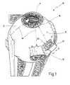
- FIG. 1shows a perspective side view of an eye prepared for operation
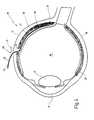
- FIGS. 2 and 3show an enlarged illustration of a region of the eye from FIG. 1 for demonstrating two steps of a method in which the invention is preferably employed;
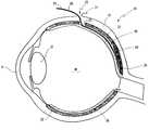
- FIG. 4shows a schematic cross-section through an eye.
- the numeral 10designates an eyeball in the figures.
- the eyeball 10comprises a cornea 11 on its front side and a sclera 12 at the remaining surface.
- the musculus rectus superioris shown in FIG. 1 at the front of the eyeball 10 .
- Four quadrantsare drawn with dot dashed lines 14 on the surface of the eyeball 10 .
- the outer, upper quadrant 15is of interest here.
- the limbus corneae, i.e. the edge region of the cornea 11is indicated in FIG. 1 with the numeral 16 .
- FIG. 4shows the lens as well as the vitreous humor of the eye, behind which the retina 19 is located.
- a sclera incision 20is made in the outer, upper quadrant 15 as clearly shown is FIG. 1 .
- the sclera incision 20is rectangular, namely at a distance a of preferably 7 to 8 mm from the limbus.
- the sclera incision 20produces the sclera flap 21 with a width b and a length c, which is preferably 4 by 4 mm in size.
- the chorioideabecomes visible beneath the flap 21 .
- an incision 25is now made through the chorioidea 22 , preferably parallel to the chorioideal vessels 23 .
- the incision 25has a width d of preferably 2.5 to 3.5 mm.
- the foil strip 30can now be passed through the incision 25 , which has a somewhat smaller width e of for example 2 mm.
- the foil strip 30has a length 1 of preferably 25 mm and a thickness x of only 50 ⁇ m. It is rounded at its front end 31 .
- the foil strip 30can be provided with a scale 32 to allow a direct reading of depth at which the strip 30 is inserted into the incision 25 .
- the surface 33 of the strip 30serves as a guiding surface which will be explained more fully below.
- An implantfor example a multiphotodiode array 40 can now be inserted into the subretinal region 36 with a slider 41 (FIG. 3 ).
- a plastic tubeis preferably employed as the slider 41 .
- the slider 41can also be provided with a scale. The direction of sliding is indicated with 42 in FIG. 3 .
- the musculus rectus superior 13 and the lateralisare employed as anchoring means.
- a sclera flap 21is prepared temporally with an edge length of 4 mm.
- the sclera incision 20can be reduced to a length of 6 mm in the assumed direction of the chorioideal vessels 23 .
- the intraocular pressureis reduced by a paracentese, so that the chorioidea 22 is no longer bulged in the region of the sclera flap 21 .
- a drop of Ornipressin(dilution 0.5 I.E./ml) is applied to the chorioidea 22 .
- the chorioidea 22is then cut at a length d of 2 mm along the direction of the large vessels 23 .
- the foil strip 30preferably of 2 mm width and rounded at its front end, is placed on the neurosensor-containing retina 19 , drawn back to the edge of the chorioidectomy, and then pushed into the subretinal region 36 .
- the implantnamely a microphotodiode chip 40
- the subretinal position of the chip 40can be derived from the implantation direction along the foil strip 30 and the length of the inserted foil, without direct intraocular observance.
- the foilis then withdrawn from the subretinal region 36 to protect the retina 19 and the chorioidea 22 and to avoid retina incarceration in the incision area, however is left on the retina 19 and chorioidea 22 while the stitches in the sclera are made.
- the access obtained by the present invention into the subretinal regioncan also be employed in other clinical situations, for example in subretinal neovascularisation, bleeding and membranes, implantations and explantations of microphotodiode chips, transplantations of pigment epithelium and retina tissue as well as the subretinal application of drugs.
- a precise placement of the chip or drugs or micro instruments ab externo at a defined position in the subretinal regionis made possible in this manner without direct intraocular observance.
- a micro-endoscopeof for example 0.9 mm diameter, including flushing channel and the option of an integrated laser or micro-gripper, can be introduced into the subretinal region on the foil.
- a fiber optic resolution(6,000 pixel) of the chip in the subretinal region is possible.
Landscapes
- Health & Medical Sciences (AREA)
- Ophthalmology & Optometry (AREA)
- Life Sciences & Earth Sciences (AREA)
- Animal Behavior & Ethology (AREA)
- Engineering & Computer Science (AREA)
- Biomedical Technology (AREA)
- Heart & Thoracic Surgery (AREA)
- Vascular Medicine (AREA)
- Nuclear Medicine, Radiotherapy & Molecular Imaging (AREA)
- Surgery (AREA)
- General Health & Medical Sciences (AREA)
- Public Health (AREA)
- Veterinary Medicine (AREA)
- Prostheses (AREA)
- Materials For Medical Uses (AREA)
- Lighting Device Outwards From Vehicle And Optical Signal (AREA)
Abstract
Description
Claims (9)
Applications Claiming Priority (3)
| Application Number | Priority Date | Filing Date | Title |
|---|---|---|---|
| DE19741487ADE19741487C2 (en) | 1997-09-19 | 1997-09-19 | Device for access to the subretinal space of an eye |
| DE19741487 | 1997-09-19 | ||
| PCT/EP1998/005953WO1999015119A1 (en) | 1997-09-19 | 1998-09-18 | Device for accessing the sub-retinal space of an eye |
Related Parent Applications (1)
| Application Number | Title | Priority Date | Filing Date |
|---|---|---|---|
| PCT/EP1998/005953Continuation-In-PartWO1999015119A1 (en) | 1997-09-19 | 1998-09-18 | Device for accessing the sub-retinal space of an eye |
Publications (1)
| Publication Number | Publication Date |
|---|---|
| US6761724B1true US6761724B1 (en) | 2004-07-13 |
Family
ID=7843017
Family Applications (1)
| Application Number | Title | Priority Date | Filing Date |
|---|---|---|---|
| US09/528,684Expired - LifetimeUS6761724B1 (en) | 1997-09-19 | 2000-03-20 | Method and device for entering the subretinal region of the eye |
Country Status (8)
| Country | Link |
|---|---|
| US (1) | US6761724B1 (en) |
| EP (1) | EP1014902B1 (en) |
| JP (1) | JP3618665B2 (en) |
| AT (1) | ATE449586T1 (en) |
| DE (1) | DE19741487C2 (en) |
| DK (1) | DK1014902T3 (en) |
| ES (1) | ES2333386T3 (en) |
| WO (1) | WO1999015119A1 (en) |
Cited By (25)
| Publication number | Priority date | Publication date | Assignee | Title |
|---|---|---|---|---|
| US20050149059A1 (en)* | 2003-12-19 | 2005-07-07 | Shibo Tang | Retinal flattener |
| US20070250135A1 (en)* | 2006-04-21 | 2007-10-25 | Bartz-Schmidt Karl U | Compound subretinal prostheses with extra-ocular parts and surgical technique therefore |
| US8428740B2 (en) | 2010-08-06 | 2013-04-23 | Nano-Retina, Inc. | Retinal prosthesis techniques |
| US8442641B2 (en) | 2010-08-06 | 2013-05-14 | Nano-Retina, Inc. | Retinal prosthesis techniques |
| US8571669B2 (en) | 2011-02-24 | 2013-10-29 | Nano-Retina, Inc. | Retinal prosthesis with efficient processing circuits |
| US20140012279A1 (en)* | 2009-07-29 | 2014-01-09 | Transcend Medical, Inc. | Ocular implant applier and methods of use |
| US8706243B2 (en) | 2009-02-09 | 2014-04-22 | Rainbow Medical Ltd. | Retinal prosthesis techniques |
| US8718784B2 (en) | 2010-01-14 | 2014-05-06 | Nano-Retina, Inc. | Penetrating electrodes for retinal stimulation |
| US9265945B2 (en) | 2009-02-09 | 2016-02-23 | Nano-Retina, Inc. | Retinal prosthesis |
| US9331791B2 (en) | 2014-01-21 | 2016-05-03 | Nano Retina Ltd. | Transfer of power and data |
| US9370417B2 (en) | 2013-03-14 | 2016-06-21 | Nano-Retina, Inc. | Foveated retinal prosthesis |
| US9474902B2 (en) | 2013-12-31 | 2016-10-25 | Nano Retina Ltd. | Wearable apparatus for delivery of power to a retinal prosthesis |
| EP3461529A1 (en)* | 2017-09-27 | 2019-04-03 | Pixium Vision SA | Tip, inserter attachment and delivery device |
| CN110960348A (en)* | 2014-09-11 | 2020-04-07 | 詹森生物科技公司 | Therapeutic agent delivery device with an advanceable cannula and needle |
| US20210186478A1 (en)* | 2018-08-29 | 2021-06-24 | Tel Hashomer Medical Research, Infrastructure And Services Ltd. | Ocular surgical instrument |
| US11058576B2 (en) | 2014-02-12 | 2021-07-13 | Gyroscope Therapeutics Limited | Method and apparatus for subretinal administration of therapeutic agent |
| US11076984B2 (en) | 2017-03-13 | 2021-08-03 | Gyroscope Therapeutics Limited | Method of performing subretinal drainage and agent delivery |
| US20210315735A1 (en)* | 2018-08-03 | 2021-10-14 | The Johns Hopkins University | Retinal implantation device |
| US11273072B2 (en) | 2017-01-13 | 2022-03-15 | Gyroscope Therapeutics Limited | Suprachoroidal injection device |
| US11338084B2 (en) | 2016-03-09 | 2022-05-24 | Gyroscope Therapeutics Limited | Apparatus for subretinal administration of therapeutic agent via a curved needle |
| US11337852B2 (en) | 2014-09-18 | 2022-05-24 | Gyroscope Therapeutics Limited | Therapeutic agent delivery device |
| US11672696B2 (en) | 2014-06-06 | 2023-06-13 | Gyroscope Therapeutics Limited | Therapeutic agent delivery device with convergent lumen |
| US11723798B2 (en) | 2014-06-06 | 2023-08-15 | Gyroscope Therapeutics Limited | Sub-retinal tangential needle catheter guide and introducer |
| US11759355B1 (en) | 2019-02-26 | 2023-09-19 | Gyroscope Therapeutics Limited | Method of delivering leading blebs and agent to subretinal space |
| US12083042B2 (en) | 2016-06-17 | 2024-09-10 | Gyroscope Therapeutics Limited | Guide apparatus for tangential entry into suprachoroidal space |
Families Citing this family (5)
| Publication number | Priority date | Publication date | Assignee | Title |
|---|---|---|---|---|
| WO2000067676A1 (en) | 1999-05-07 | 2000-11-16 | Eberhard-Karls-Universität Tübingen Universitätsklinikum | Retina implant and method for producing the same |
| US6389317B1 (en) | 2000-03-31 | 2002-05-14 | Optobionics Corporation | Multi-phasic microphotodetector retinal implant with variable voltage and current capability |
| US7037943B2 (en) | 2001-04-10 | 2006-05-02 | Optobionics Corporation | Retinal treatment method |
| WO2003061537A1 (en) | 2002-01-17 | 2003-07-31 | Masachusetts Eye And Ear Infirmary | Minimally invasive retinal prosthesis |
| DE102004002379A1 (en)* | 2004-01-15 | 2005-08-18 | Iip-Technologies Gmbh | Neurological tool |
Citations (21)
| Publication number | Priority date | Publication date | Assignee | Title |
|---|---|---|---|---|
| US4136459A (en)* | 1976-02-25 | 1979-01-30 | Karl Suss Kg | Parallelizing gauge in a wedge error correction head |
| US4452235A (en)* | 1982-01-04 | 1984-06-05 | Reynolds Alvin E | Method for corneal curvature adjustment |
| EP0177470A2 (en)* | 1984-10-02 | 1986-04-09 | AB AKERLUND & RAUSING | A tube and a method and a device for manufacturing of the tube |
| US4641648A (en) | 1985-09-27 | 1987-02-10 | Marshall Shapiro | Surgical instrument |
| US4722724A (en) | 1986-06-23 | 1988-02-02 | Stanley Schocket | Anterior chamber tube shunt to an encircling band, and related surgical procedure |
| US4747393A (en) | 1983-01-05 | 1988-05-31 | Albert Medwid | Visceral retractor |
| DE3817112A1 (en)* | 1987-05-20 | 1988-12-01 | Hitachi Chemical Co Ltd | Sealing material and cylinder head gasket |
| EP0460320A2 (en) | 1989-08-08 | 1991-12-11 | Alan Y. Chow | Artificial retina device |
| US5090955A (en)* | 1990-07-12 | 1992-02-25 | University Of Miami | Gel injection adjustable keratoplasty |
| US5370652A (en) | 1992-10-08 | 1994-12-06 | Kellan; Robert E. | Surgical knife blade for making sutureless incisions in the eye and methods therefor |
| US5507807A (en) | 1994-03-01 | 1996-04-16 | Shippert; Ronald D. | Apparatus for the release of a substance within a patient |
| US5562691A (en)* | 1993-09-30 | 1996-10-08 | Nidek Co., Ltd. | Ophthalmic surgical apparatus |
| US5578040A (en)* | 1994-06-14 | 1996-11-26 | Smith; Albert C. | Ocular repair system and apparatus |
| US5643437A (en)* | 1995-11-03 | 1997-07-01 | Huron Tech Canada, Inc. | Co-generation of ammonium persulfate anodically and alkaline hydrogen peroxide cathodically with cathode products ratio control |
| US5651783A (en)* | 1995-12-20 | 1997-07-29 | Reynard; Michael | Fiber optic sleeve for surgical instruments |
| US5688264A (en)* | 1992-10-19 | 1997-11-18 | The University Of Miami | Laser treatment for retinal detachment |
| US5817075A (en)* | 1989-08-14 | 1998-10-06 | Photogenesis, Inc. | Method for preparation and transplantation of planar implants and surgical instrument therefor |
| EP0872335A2 (en)* | 1993-02-25 | 1998-10-21 | Alusuisse Technology & Management AG | Composite material |
| US5941250A (en)* | 1996-11-21 | 1999-08-24 | University Of Louisville Research Foundation Inc. | Retinal tissue implantation method |
| US6050999A (en)* | 1997-12-18 | 2000-04-18 | Keravision, Inc. | Corneal implant introducer and method of use |
| US6159218A (en)* | 1999-05-19 | 2000-12-12 | Aramant; Robert B. | Retinal tissue implantation tool |
- 1997
- 1997-09-19DEDE19741487Apatent/DE19741487C2/ennot_activeExpired - Lifetime
- 1998
- 1998-09-18EPEP98950052Apatent/EP1014902B1/ennot_activeExpired - Lifetime
- 1998-09-18WOPCT/EP1998/005953patent/WO1999015119A1/enactiveApplication Filing
- 1998-09-18JPJP2000512496Apatent/JP3618665B2/ennot_activeExpired - Lifetime
- 1998-09-18ATAT98950052Tpatent/ATE449586T1/ennot_activeIP Right Cessation
- 1998-09-18ESES98950052Tpatent/ES2333386T3/ennot_activeExpired - Lifetime
- 1998-09-18DKDK98950052.5Tpatent/DK1014902T3/enactive
- 2000
- 2000-03-20USUS09/528,684patent/US6761724B1/ennot_activeExpired - Lifetime
Patent Citations (22)
| Publication number | Priority date | Publication date | Assignee | Title |
|---|---|---|---|---|
| US4136459A (en)* | 1976-02-25 | 1979-01-30 | Karl Suss Kg | Parallelizing gauge in a wedge error correction head |
| US4452235A (en)* | 1982-01-04 | 1984-06-05 | Reynolds Alvin E | Method for corneal curvature adjustment |
| US4747393A (en) | 1983-01-05 | 1988-05-31 | Albert Medwid | Visceral retractor |
| EP0177470A2 (en)* | 1984-10-02 | 1986-04-09 | AB AKERLUND & RAUSING | A tube and a method and a device for manufacturing of the tube |
| US4641648A (en) | 1985-09-27 | 1987-02-10 | Marshall Shapiro | Surgical instrument |
| US4722724A (en) | 1986-06-23 | 1988-02-02 | Stanley Schocket | Anterior chamber tube shunt to an encircling band, and related surgical procedure |
| DE3817112A1 (en)* | 1987-05-20 | 1988-12-01 | Hitachi Chemical Co Ltd | Sealing material and cylinder head gasket |
| EP0460320A2 (en) | 1989-08-08 | 1991-12-11 | Alan Y. Chow | Artificial retina device |
| US5817075A (en)* | 1989-08-14 | 1998-10-06 | Photogenesis, Inc. | Method for preparation and transplantation of planar implants and surgical instrument therefor |
| US5090955A (en)* | 1990-07-12 | 1992-02-25 | University Of Miami | Gel injection adjustable keratoplasty |
| US5370652A (en) | 1992-10-08 | 1994-12-06 | Kellan; Robert E. | Surgical knife blade for making sutureless incisions in the eye and methods therefor |
| US5688264A (en)* | 1992-10-19 | 1997-11-18 | The University Of Miami | Laser treatment for retinal detachment |
| EP0872335A2 (en)* | 1993-02-25 | 1998-10-21 | Alusuisse Technology & Management AG | Composite material |
| US5562691A (en)* | 1993-09-30 | 1996-10-08 | Nidek Co., Ltd. | Ophthalmic surgical apparatus |
| US5507807A (en) | 1994-03-01 | 1996-04-16 | Shippert; Ronald D. | Apparatus for the release of a substance within a patient |
| US5611799A (en)* | 1994-06-14 | 1997-03-18 | Smith; Albert C. | Ocular repair method |
| US5578040A (en)* | 1994-06-14 | 1996-11-26 | Smith; Albert C. | Ocular repair system and apparatus |
| US5643437A (en)* | 1995-11-03 | 1997-07-01 | Huron Tech Canada, Inc. | Co-generation of ammonium persulfate anodically and alkaline hydrogen peroxide cathodically with cathode products ratio control |
| US5651783A (en)* | 1995-12-20 | 1997-07-29 | Reynard; Michael | Fiber optic sleeve for surgical instruments |
| US5941250A (en)* | 1996-11-21 | 1999-08-24 | University Of Louisville Research Foundation Inc. | Retinal tissue implantation method |
| US6050999A (en)* | 1997-12-18 | 2000-04-18 | Keravision, Inc. | Corneal implant introducer and method of use |
| US6159218A (en)* | 1999-05-19 | 2000-12-12 | Aramant; Robert B. | Retinal tissue implantation tool |
Cited By (36)
| Publication number | Priority date | Publication date | Assignee | Title |
|---|---|---|---|---|
| US20050149059A1 (en)* | 2003-12-19 | 2005-07-07 | Shibo Tang | Retinal flattener |
| US20070250135A1 (en)* | 2006-04-21 | 2007-10-25 | Bartz-Schmidt Karl U | Compound subretinal prostheses with extra-ocular parts and surgical technique therefore |
| US9907969B2 (en) | 2009-02-09 | 2018-03-06 | Nano-Retina, Inc. | Retinal prosthesis with an external power source |
| US8706243B2 (en) | 2009-02-09 | 2014-04-22 | Rainbow Medical Ltd. | Retinal prosthesis techniques |
| US9198753B2 (en) | 2009-02-09 | 2015-12-01 | Nano-Retina Inc. | Techniques for powering a retinal prosthesis |
| US9265945B2 (en) | 2009-02-09 | 2016-02-23 | Nano-Retina, Inc. | Retinal prosthesis |
| US9566191B2 (en) | 2009-02-09 | 2017-02-14 | Nano-Retina, Inc. | Retinal prosthesis with visible-light filter |
| US9549845B2 (en)* | 2009-07-29 | 2017-01-24 | Novartis Ag | Ocular implant applier and methods of use |
| US20140012279A1 (en)* | 2009-07-29 | 2014-01-09 | Transcend Medical, Inc. | Ocular implant applier and methods of use |
| US8718784B2 (en) | 2010-01-14 | 2014-05-06 | Nano-Retina, Inc. | Penetrating electrodes for retinal stimulation |
| US8428740B2 (en) | 2010-08-06 | 2013-04-23 | Nano-Retina, Inc. | Retinal prosthesis techniques |
| US8442641B2 (en) | 2010-08-06 | 2013-05-14 | Nano-Retina, Inc. | Retinal prosthesis techniques |
| US9192464B2 (en) | 2011-02-24 | 2015-11-24 | Nano-Retina, Inc. | Retinal prosthesis with efficient processing circuits |
| US8571669B2 (en) | 2011-02-24 | 2013-10-29 | Nano-Retina, Inc. | Retinal prosthesis with efficient processing circuits |
| US9370417B2 (en) | 2013-03-14 | 2016-06-21 | Nano-Retina, Inc. | Foveated retinal prosthesis |
| US9474902B2 (en) | 2013-12-31 | 2016-10-25 | Nano Retina Ltd. | Wearable apparatus for delivery of power to a retinal prosthesis |
| US9331791B2 (en) | 2014-01-21 | 2016-05-03 | Nano Retina Ltd. | Transfer of power and data |
| US11554042B2 (en) | 2014-02-12 | 2023-01-17 | Gyroscope Therapeutics Limited | Method and apparatus for subretinal administration of therapeutic agent |
| US12409064B2 (en) | 2014-02-12 | 2025-09-09 | Genentech, Inc. | Method and apparatus for suprachoroidal administration of therapeutic agent |
| US11058576B2 (en) | 2014-02-12 | 2021-07-13 | Gyroscope Therapeutics Limited | Method and apparatus for subretinal administration of therapeutic agent |
| US11998482B2 (en) | 2014-02-12 | 2024-06-04 | Gyroscope Therapeutics Limited | Method and apparatus for subretinal administration of therapeutic agent |
| US11672696B2 (en) | 2014-06-06 | 2023-06-13 | Gyroscope Therapeutics Limited | Therapeutic agent delivery device with convergent lumen |
| US11723798B2 (en) | 2014-06-06 | 2023-08-15 | Gyroscope Therapeutics Limited | Sub-retinal tangential needle catheter guide and introducer |
| CN110960348A (en)* | 2014-09-11 | 2020-04-07 | 詹森生物科技公司 | Therapeutic agent delivery device with an advanceable cannula and needle |
| US11337852B2 (en) | 2014-09-18 | 2022-05-24 | Gyroscope Therapeutics Limited | Therapeutic agent delivery device |
| US11338084B2 (en) | 2016-03-09 | 2022-05-24 | Gyroscope Therapeutics Limited | Apparatus for subretinal administration of therapeutic agent via a curved needle |
| US12083042B2 (en) | 2016-06-17 | 2024-09-10 | Gyroscope Therapeutics Limited | Guide apparatus for tangential entry into suprachoroidal space |
| US11273072B2 (en) | 2017-01-13 | 2022-03-15 | Gyroscope Therapeutics Limited | Suprachoroidal injection device |
| US11076984B2 (en) | 2017-03-13 | 2021-08-03 | Gyroscope Therapeutics Limited | Method of performing subretinal drainage and agent delivery |
| WO2019063655A1 (en)* | 2017-09-27 | 2019-04-04 | Pixium Vision Sa | Tip, inserter attachment and delivery device |
| EP3461529A1 (en)* | 2017-09-27 | 2019-04-03 | Pixium Vision SA | Tip, inserter attachment and delivery device |
| US11583440B2 (en) | 2017-09-27 | 2023-02-21 | Pixium Vision Sa | Tip, inserter attachment and delivery device |
| US20210315735A1 (en)* | 2018-08-03 | 2021-10-14 | The Johns Hopkins University | Retinal implantation device |
| US11911018B2 (en)* | 2018-08-29 | 2024-02-27 | Tel Hashomer Medical Research, Infrastructure And Services Ltd. | Ocular surgical instrument |
| US20210186478A1 (en)* | 2018-08-29 | 2021-06-24 | Tel Hashomer Medical Research, Infrastructure And Services Ltd. | Ocular surgical instrument |
| US11759355B1 (en) | 2019-02-26 | 2023-09-19 | Gyroscope Therapeutics Limited | Method of delivering leading blebs and agent to subretinal space |
Also Published As
| Publication number | Publication date |
|---|---|
| DE19741487C2 (en) | 2000-08-31 |
| JP2001517486A (en) | 2001-10-09 |
| DK1014902T3 (en) | 2010-03-15 |
| ATE449586T1 (en) | 2009-12-15 |
| EP1014902B1 (en) | 2009-11-25 |
| DE19741487A1 (en) | 1999-04-08 |
| WO1999015119A1 (en) | 1999-04-01 |
| JP3618665B2 (en) | 2005-02-09 |
| EP1014902A1 (en) | 2000-07-05 |
| ES2333386T3 (en) | 2010-02-19 |
Similar Documents
| Publication | Publication Date | Title |
|---|---|---|
| US6761724B1 (en) | Method and device for entering the subretinal region of the eye | |
| AU2002365403B2 (en) | Ophthalmic microsurgical system | |
| US8535333B2 (en) | Ocular implant applier and methods of use | |
| JP7497406B2 (en) | Ocular Implant System | |
| EP3344202B1 (en) | Illuminated ophthalmic cannula | |
| US9554941B2 (en) | Ocular implant delivery systems and methods | |
| KR940006109B1 (en) | Intravenous puncture indicator for intravenous needle | |
| US20100134759A1 (en) | Digital imaging system for eye procedures | |
| JP4791009B2 (en) | Vitreous surgery contact lens retaining ring | |
| KR20160021201A (en) | Inserter for tubular medical implant devices | |
| JP2005515027A (en) | Fixing the intraocular lens to the iris | |
| JP2008307384A (en) | Cannula | |
| HUP0301786A2 (en) | Systems and methods for reducing intraocular pressure | |
| KR20110120900A (en) | Device for drawing fluid | |
| US11576814B2 (en) | Ophthalmic instrument | |
| TW202415354A (en) | Ocular needle guide and method to facilitate access to an eye | |
| US11806281B2 (en) | Ophthalmic surgery instrument | |
| KR102854339B1 (en) | Anterior capsular incision assist device | |
| US20230079304A1 (en) | Slotted ocular lens |
Legal Events
| Date | Code | Title | Description |
|---|---|---|---|
| AS | Assignment | Owner name:EBERHARD-KARLS-UNIVERSITAT TUBINGEN UNIVERSITATSKL Free format text:ASSIGNMENT OF ASSIGNORS INTEREST;ASSIGNORS:ZRENNER, EBERHART;GABEL, VEIT-PETER;KOBUCH, KARIN;REEL/FRAME:010957/0897 Effective date:20000607 | |
| FEPP | Fee payment procedure | Free format text:PAYOR NUMBER ASSIGNED (ORIGINAL EVENT CODE: ASPN); ENTITY STATUS OF PATENT OWNER: LARGE ENTITY | |
| STCF | Information on status: patent grant | Free format text:PATENTED CASE | |
| AS | Assignment | Owner name:RETINA IMPLANT GMBH, GERMANY Free format text:ASSIGNMENT OF ASSIGNORS INTEREST;ASSIGNOR:EBERHARD-KARLS-UNIVERSITAT TUBINGEN UNIVERSITATSKLINIKUM;REEL/FRAME:018934/0898 Effective date:20070130 | |
| FEPP | Fee payment procedure | Free format text:PAYOR NUMBER ASSIGNED (ORIGINAL EVENT CODE: ASPN); ENTITY STATUS OF PATENT OWNER: LARGE ENTITY Free format text:PAYER NUMBER DE-ASSIGNED (ORIGINAL EVENT CODE: RMPN); ENTITY STATUS OF PATENT OWNER: LARGE ENTITY | |
| FPAY | Fee payment | Year of fee payment:4 | |
| AS | Assignment | Owner name:RETINA IMPLANT AG, GERMANY Free format text:CHANGE OF NAME;ASSIGNOR:RETINA IMPLANT GMBH;REEL/FRAME:021965/0786 Effective date:20080624 | |
| FPAY | Fee payment | Year of fee payment:8 | |
| FPAY | Fee payment | Year of fee payment:12 |