US6761719B2 - Superelastic spinal stabilization system and method - Google Patents
Superelastic spinal stabilization system and methodDownload PDFInfo
- Publication number
- US6761719B2 US6761719B2US09/960,770US96077001AUS6761719B2US 6761719 B2US6761719 B2US 6761719B2US 96077001 AUS96077001 AUS 96077001AUS 6761719 B2US6761719 B2US 6761719B2
- Authority
- US
- United States
- Prior art keywords
- vertebral bodies
- stress
- shape
- spinal column
- configuration
- Prior art date
- Legal status (The legal status is an assumption and is not a legal conclusion. Google has not performed a legal analysis and makes no representation as to the accuracy of the status listed.)
- Expired - Fee Related, expires
Links
- 238000000034methodMethods0.000titleclaimsdescription14
- 230000006641stabilisationEffects0.000titleabstractdescription44
- 238000011105stabilizationMethods0.000titleabstractdescription44
- 239000012781shape memory materialSubstances0.000claimsabstractdescription34
- 229910000734martensiteInorganic materials0.000claimsabstractdescription22
- 238000006073displacement reactionMethods0.000claimsabstractdescription18
- 230000000087stabilizing effectEffects0.000claimsabstractdescription17
- 230000036760body temperatureEffects0.000claimsabstractdescription16
- 230000004044responseEffects0.000claimsabstractdescription14
- 230000001747exhibiting effectEffects0.000claimsabstractdescription13
- 239000000463materialSubstances0.000claimsdescription38
- 229910001566austeniteInorganic materials0.000claimsdescription11
- 230000002441reversible effectEffects0.000claimsdescription11
- 230000008859changeEffects0.000claimsdescription8
- 239000007943implantSubstances0.000claimsdescription5
- 230000009467reductionEffects0.000claimsdescription5
- 230000001131transforming effectEffects0.000claimsdescription5
- 229910001092metal group alloyInorganic materials0.000claimsdescription3
- 229920000642polymerPolymers0.000claims1
- 238000002407reformingMethods0.000claims1
- 210000000988bone and boneAnatomy0.000abstractdescription44
- 229920000147Styrene maleic anhydridePolymers0.000description30
- 230000009466transformationEffects0.000description12
- 238000007747platingMethods0.000description9
- RTAQQCXQSZGOHL-UHFFFAOYSA-NTitaniumChemical compound[Ti]RTAQQCXQSZGOHL-UHFFFAOYSA-N0.000description7
- 230000003247decreasing effectEffects0.000description7
- 239000010936titaniumSubstances0.000description7
- PXHVJJICTQNCMI-UHFFFAOYSA-NNickelChemical compound[Ni]PXHVJJICTQNCMI-UHFFFAOYSA-N0.000description6
- 238000013459approachMethods0.000description6
- 230000008901benefitEffects0.000description6
- 230000004927fusionEffects0.000description6
- 229910001000nickel titaniumInorganic materials0.000description6
- 210000001519tissueAnatomy0.000description6
- 229910052719titaniumInorganic materials0.000description6
- 210000004705lumbosacral regionAnatomy0.000description5
- HLXZNVUGXRDIFK-UHFFFAOYSA-Nnickel titaniumChemical group[Ti].[Ti].[Ti].[Ti].[Ti].[Ti].[Ti].[Ti].[Ti].[Ti].[Ti].[Ni].[Ni].[Ni].[Ni].[Ni].[Ni].[Ni].[Ni].[Ni].[Ni].[Ni].[Ni].[Ni].[Ni]HLXZNVUGXRDIFK-UHFFFAOYSA-N0.000description5
- 229910045601alloyInorganic materials0.000description4
- 239000000956alloySubstances0.000description4
- 208000014674injuryDiseases0.000description4
- 230000007170pathologyEffects0.000description4
- 239000000560biocompatible materialSubstances0.000description3
- -1for exampleSubstances0.000description3
- 229910052759nickelInorganic materials0.000description3
- 239000010935stainless steelSubstances0.000description3
- 229910001220stainless steelInorganic materials0.000description3
- 210000000115thoracic cavityAnatomy0.000description3
- 230000007704transitionEffects0.000description3
- 230000008733traumaEffects0.000description3
- 210000003484anatomyAnatomy0.000description2
- 230000000295complement effectEffects0.000description2
- 230000000694effectsEffects0.000description2
- 238000003780insertionMethods0.000description2
- 230000037431insertionEffects0.000description2
- 238000012986modificationMethods0.000description2
- 230000004048modificationEffects0.000description2
- 210000000954sacrococcygeal regionAnatomy0.000description2
- 229910001285shape-memory alloyInorganic materials0.000description2
- 229920000431shape-memory polymerPolymers0.000description2
- 229910052720vanadiumInorganic materials0.000description2
- 238000003466weldingMethods0.000description2
- RYGMFSIKBFXOCR-UHFFFAOYSA-NCopperChemical compound[Cu]RYGMFSIKBFXOCR-UHFFFAOYSA-N0.000description1
- 206010027677Fractures and dislocationsDiseases0.000description1
- 241001465754MetazoaSpecies0.000description1
- 206010028980NeoplasmDiseases0.000description1
- 229910000990Ni alloyInorganic materials0.000description1
- BQCADISMDOOEFD-UHFFFAOYSA-NSilverChemical compound[Ag]BQCADISMDOOEFD-UHFFFAOYSA-N0.000description1
- 206010058907Spinal deformityDiseases0.000description1
- 208000020307Spinal diseaseDiseases0.000description1
- 229910001069Ti alloyInorganic materials0.000description1
- 208000027418Wounds and injuryDiseases0.000description1
- HCHKCACWOHOZIP-UHFFFAOYSA-NZincChemical compound[Zn]HCHKCACWOHOZIP-UHFFFAOYSA-N0.000description1
- QCWXUUIWCKQGHC-UHFFFAOYSA-NZirconiumChemical compound[Zr]QCWXUUIWCKQGHC-UHFFFAOYSA-N0.000description1
- 230000009471actionEffects0.000description1
- 230000004075alterationEffects0.000description1
- 238000004873anchoringMethods0.000description1
- 229910052793cadmiumInorganic materials0.000description1
- BDOSMKKIYDKNTQ-UHFFFAOYSA-Ncadmium atomChemical compound[Cd]BDOSMKKIYDKNTQ-UHFFFAOYSA-N0.000description1
- 230000015556catabolic processEffects0.000description1
- 229910052802copperInorganic materials0.000description1
- 239000010949copperSubstances0.000description1
- 238000012937correctionMethods0.000description1
- 230000007797corrosionEffects0.000description1
- 238000005260corrosionMethods0.000description1
- 230000006378damageEffects0.000description1
- 238000006731degradation reactionMethods0.000description1
- 238000011161developmentMethods0.000description1
- 229910003460diamondInorganic materials0.000description1
- 239000010432diamondSubstances0.000description1
- 201000010099diseaseDiseases0.000description1
- 208000037265diseases, disorders, signs and symptomsDiseases0.000description1
- 230000006870functionEffects0.000description1
- KHYBPSFKEHXSLX-UHFFFAOYSA-NiminotitaniumChemical compound[Ti]=NKHYBPSFKEHXSLX-UHFFFAOYSA-N0.000description1
- 238000000338in vitroMethods0.000description1
- 230000003993interactionEffects0.000description1
- 230000036244malformationEffects0.000description1
- 230000007246mechanismEffects0.000description1
- 230000003446memory effectEffects0.000description1
- 229910052751metalInorganic materials0.000description1
- 239000002184metalSubstances0.000description1
- 150000002739metalsChemical class0.000description1
- 239000000203mixtureSubstances0.000description1
- 208000015122neurodegenerative diseaseDiseases0.000description1
- 230000035515penetrationEffects0.000description1
- 230000002980postoperative effectEffects0.000description1
- 230000001737promoting effectEffects0.000description1
- 238000011160researchMethods0.000description1
- 238000010079rubber tappingMethods0.000description1
- 229910052709silverInorganic materials0.000description1
- 239000004332silverSubstances0.000description1
- 210000004872soft tissueAnatomy0.000description1
- 229910052725zincInorganic materials0.000description1
- 239000011701zincSubstances0.000description1
- 229910052726zirconiumInorganic materials0.000description1
Images


Classifications
- A—HUMAN NECESSITIES
- A61—MEDICAL OR VETERINARY SCIENCE; HYGIENE
- A61B—DIAGNOSIS; SURGERY; IDENTIFICATION
- A61B17/00—Surgical instruments, devices or methods
- A61B17/56—Surgical instruments or methods for treatment of bones or joints; Devices specially adapted therefor
- A61B17/58—Surgical instruments or methods for treatment of bones or joints; Devices specially adapted therefor for osteosynthesis, e.g. bone plates, screws or setting implements
- A61B17/68—Internal fixation devices, including fasteners and spinal fixators, even if a part thereof projects from the skin
- A61B17/70—Spinal positioners or stabilisers, e.g. stabilisers comprising fluid filler in an implant
- A61B17/7001—Screws or hooks combined with longitudinal elements which do not contact vertebrae
- A61B17/7002—Longitudinal elements, e.g. rods
- A61B17/7011—Longitudinal element being non-straight, e.g. curved, angled or branched
- A—HUMAN NECESSITIES
- A61—MEDICAL OR VETERINARY SCIENCE; HYGIENE
- A61B—DIAGNOSIS; SURGERY; IDENTIFICATION
- A61B17/00—Surgical instruments, devices or methods
- A61B17/56—Surgical instruments or methods for treatment of bones or joints; Devices specially adapted therefor
- A61B17/58—Surgical instruments or methods for treatment of bones or joints; Devices specially adapted therefor for osteosynthesis, e.g. bone plates, screws or setting implements
- A61B17/68—Internal fixation devices, including fasteners and spinal fixators, even if a part thereof projects from the skin
- A61B17/70—Spinal positioners or stabilisers, e.g. stabilisers comprising fluid filler in an implant
- A61B17/7059—Cortical plates
- A—HUMAN NECESSITIES
- A61—MEDICAL OR VETERINARY SCIENCE; HYGIENE
- A61B—DIAGNOSIS; SURGERY; IDENTIFICATION
- A61B17/00—Surgical instruments, devices or methods
- A61B17/56—Surgical instruments or methods for treatment of bones or joints; Devices specially adapted therefor
- A61B17/58—Surgical instruments or methods for treatment of bones or joints; Devices specially adapted therefor for osteosynthesis, e.g. bone plates, screws or setting implements
- A61B17/68—Internal fixation devices, including fasteners and spinal fixators, even if a part thereof projects from the skin
- A61B17/70—Spinal positioners or stabilisers, e.g. stabilisers comprising fluid filler in an implant
- A—HUMAN NECESSITIES
- A61—MEDICAL OR VETERINARY SCIENCE; HYGIENE
- A61B—DIAGNOSIS; SURGERY; IDENTIFICATION
- A61B17/00—Surgical instruments, devices or methods
- A61B17/56—Surgical instruments or methods for treatment of bones or joints; Devices specially adapted therefor
- A61B17/58—Surgical instruments or methods for treatment of bones or joints; Devices specially adapted therefor for osteosynthesis, e.g. bone plates, screws or setting implements
- A61B17/68—Internal fixation devices, including fasteners and spinal fixators, even if a part thereof projects from the skin
- A61B17/80—Cortical plates, i.e. bone plates; Instruments for holding or positioning cortical plates, or for compressing bones attached to cortical plates
- A61B17/8033—Cortical plates, i.e. bone plates; Instruments for holding or positioning cortical plates, or for compressing bones attached to cortical plates having indirect contact with screw heads, or having contact with screw heads maintained with the aid of additional components, e.g. nuts, wedges or head covers
- A61B17/8042—Cortical plates, i.e. bone plates; Instruments for holding or positioning cortical plates, or for compressing bones attached to cortical plates having indirect contact with screw heads, or having contact with screw heads maintained with the aid of additional components, e.g. nuts, wedges or head covers the additional component being a cover over the screw head
- A—HUMAN NECESSITIES
- A61—MEDICAL OR VETERINARY SCIENCE; HYGIENE
- A61B—DIAGNOSIS; SURGERY; IDENTIFICATION
- A61B17/00—Surgical instruments, devices or methods
- A61B2017/00831—Material properties
- A61B2017/00867—Material properties shape memory effect
- A—HUMAN NECESSITIES
- A61—MEDICAL OR VETERINARY SCIENCE; HYGIENE
- A61F—FILTERS IMPLANTABLE INTO BLOOD VESSELS; PROSTHESES; DEVICES PROVIDING PATENCY TO, OR PREVENTING COLLAPSING OF, TUBULAR STRUCTURES OF THE BODY, e.g. STENTS; ORTHOPAEDIC, NURSING OR CONTRACEPTIVE DEVICES; FOMENTATION; TREATMENT OR PROTECTION OF EYES OR EARS; BANDAGES, DRESSINGS OR ABSORBENT PADS; FIRST-AID KITS
- A61F2/00—Filters implantable into blood vessels; Prostheses, i.e. artificial substitutes or replacements for parts of the body; Appliances for connecting them with the body; Devices providing patency to, or preventing collapsing of, tubular structures of the body, e.g. stents
- A61F2/02—Prostheses implantable into the body
- A61F2/30—Joints
- A61F2002/30001—Additional features of subject-matter classified in A61F2/28, A61F2/30 and subgroups thereof
- A61F2002/30003—Material related properties of the prosthesis or of a coating on the prosthesis
- A61F2002/3006—Properties of materials and coating materials
- A61F2002/30092—Properties of materials and coating materials using shape memory or superelastic materials, e.g. nitinol
- A—HUMAN NECESSITIES
- A61—MEDICAL OR VETERINARY SCIENCE; HYGIENE
- A61F—FILTERS IMPLANTABLE INTO BLOOD VESSELS; PROSTHESES; DEVICES PROVIDING PATENCY TO, OR PREVENTING COLLAPSING OF, TUBULAR STRUCTURES OF THE BODY, e.g. STENTS; ORTHOPAEDIC, NURSING OR CONTRACEPTIVE DEVICES; FOMENTATION; TREATMENT OR PROTECTION OF EYES OR EARS; BANDAGES, DRESSINGS OR ABSORBENT PADS; FIRST-AID KITS
- A61F2/00—Filters implantable into blood vessels; Prostheses, i.e. artificial substitutes or replacements for parts of the body; Appliances for connecting them with the body; Devices providing patency to, or preventing collapsing of, tubular structures of the body, e.g. stents
- A61F2/02—Prostheses implantable into the body
- A61F2/30—Joints
- A61F2/44—Joints for the spine, e.g. vertebrae, spinal discs
- A61F2002/449—Joints for the spine, e.g. vertebrae, spinal discs comprising multiple spinal implants located in different intervertebral spaces or in different vertebrae
- A—HUMAN NECESSITIES
- A61—MEDICAL OR VETERINARY SCIENCE; HYGIENE
- A61F—FILTERS IMPLANTABLE INTO BLOOD VESSELS; PROSTHESES; DEVICES PROVIDING PATENCY TO, OR PREVENTING COLLAPSING OF, TUBULAR STRUCTURES OF THE BODY, e.g. STENTS; ORTHOPAEDIC, NURSING OR CONTRACEPTIVE DEVICES; FOMENTATION; TREATMENT OR PROTECTION OF EYES OR EARS; BANDAGES, DRESSINGS OR ABSORBENT PADS; FIRST-AID KITS
- A61F2210/00—Particular material properties of prostheses classified in groups A61F2/00 - A61F2/26 or A61F2/82 or A61F9/00 or A61F11/00 or subgroups thereof
- A61F2210/0014—Particular material properties of prostheses classified in groups A61F2/00 - A61F2/26 or A61F2/82 or A61F9/00 or A61F11/00 or subgroups thereof using shape memory or superelastic materials, e.g. nitinol
- Y—GENERAL TAGGING OF NEW TECHNOLOGICAL DEVELOPMENTS; GENERAL TAGGING OF CROSS-SECTIONAL TECHNOLOGIES SPANNING OVER SEVERAL SECTIONS OF THE IPC; TECHNICAL SUBJECTS COVERED BY FORMER USPC CROSS-REFERENCE ART COLLECTIONS [XRACs] AND DIGESTS
- Y10—TECHNICAL SUBJECTS COVERED BY FORMER USPC
- Y10S—TECHNICAL SUBJECTS COVERED BY FORMER USPC CROSS-REFERENCE ART COLLECTIONS [XRACs] AND DIGESTS
- Y10S606/00—Surgery
- Y10S606/907—Composed of particular material or coated
- Y10S606/91—Polymer
- Y—GENERAL TAGGING OF NEW TECHNOLOGICAL DEVELOPMENTS; GENERAL TAGGING OF CROSS-SECTIONAL TECHNOLOGIES SPANNING OVER SEVERAL SECTIONS OF THE IPC; TECHNICAL SUBJECTS COVERED BY FORMER USPC CROSS-REFERENCE ART COLLECTIONS [XRACs] AND DIGESTS
- Y10—TECHNICAL SUBJECTS COVERED BY FORMER USPC
- Y10S—TECHNICAL SUBJECTS COVERED BY FORMER USPC CROSS-REFERENCE ART COLLECTIONS [XRACs] AND DIGESTS
- Y10S606/00—Surgery
- Y10S606/907—Composed of particular material or coated
- Y10S606/911—Memory material
Definitions
- the present inventionrelates generally to the field of instrumentation and systems for treatment of the spine, and more particularly to a device for flexibly stabilizing the cervical spine.
- the spineis subject to various pathologies that compromise its load bearing and support capabilities.
- pathologies of the spineinclude, for example, degenerative diseases, the effects of tumors and, of course, fractures and dislocations attributable to physical trauma.
- spinal motion segmentswhich include two adjacent vertebrae and the disc tissue or disc space therebetween
- spinal motion segmentswhich include two adjacent vertebrae and the disc tissue or disc space therebetween
- spinal motion segmentswhich include two adjacent vertebrae and the disc tissue or disc space therebetween
- spinal motion segmentswhich include two adjacent vertebrae and the disc tissue or disc space therebetween
- corrective measuresare indicated to insure the proper spacing of adjacent vertebrae formerly separated by the removed disc tissue.
- the adjacent vertebraeare fused together using a graft structure formed of transplanted bone tissue, an artificial fusion element, or other suitable compositions.
- Elongated rigid plateshave been helpful in the stabilization and fixation of the spine when used alone or in conjunction with a grafting procedure, especially in the thoracic and lumbar regions of the spine.
- These plating systemsalso have the potential advantage of increasing union rates, decreasing graft collapse, minimizing subsequent kyphotic deformity, and decreasing the need for bulky or rigid postoperative immobilization.
- rigid internal fixation systemsmay improve the overall quality of life of the patient and may provide the opportunity for earlier rehabilitation.
- the systemshould also be able to maintain stress levels below the endurance limits of the plate material, while at the same time exceeding the strength of the anatomic structures or vertebrae to which the plating system is engaged. Additionally, the system should preferably be capable of accommodating for the natural movement of the vertebrae relative to one another, including torsional movement during rotation of the spine and translational movement during flexion or extension of the spine.
- a method for stabilizing at least a portion of the spinal columncomprising providing a member at least partially formed of a material capable of exhibiting superelastic characteristics at about body temperature, and engaging the member to at least two vertebral bodies.
- a systemfor stabilizing at least a portion of a spinal column, comprising an implant disposed between two adjacent vertebrae, and a member anchored to the two adjacent vertebrae and being at least partially formed of a material capable of exhibiting superelastic characteristics at about body temperature.
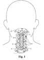
- FIG. 1is an anterior view of the cervical region of the spine showing a spinal stabilization system according to one embodiment of the present invention attached to two cervical vertebrae.
- FIG. 2is a partial cross-sectional view of the spinal stabilization system depicted in FIG. 1, with the screws disposed through holes in the stabilization plate and engaged to a cervical vertebra.
- FIG. 4 ais a top view of a stabilization plate according to an embodiment of the present invention, shown in an unstressed configuration.
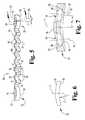
- FIG. 5is a side elevation view of the stabilization plate depicted in FIG. 4 a.
- FIG. 6is an end elevation view of the stabilization plate depicted in FIG. 4 a.
- FIG. 7is an angled cross-sectional view of the stabilization plate depicted in FIG. 4 a , taken along line 7 — 7 of FIG. 4 a.
- FIG. 10is a top view of a stabilization plate according to another embodiment of the present invention.
- FIG. 12is a top view of a stabilization rod according to another embodiment of the present invention.
- FIG. 13 bis a side elevation view of the stabilization rod depicted in FIG. 12, shown in a stresses configuration.
- FIGS. 1-2depict a spinal stabilization system 20 according to one embodiment of the present invention for stabilizing at least a portion of the vertebral column.
- Stabilization system 20is shown attached to the cervical region of the vertebral column, extending across a plurality of spinal motion segments, such as cervical vertebrae V.
- system 20may also be utilized in other areas of the spine, such as the thoracic, lumbar, lumbo sacral and sacral regions of the spine.
- system 20can extend across any number of vertebrae V, including two adjacent vertebrae V.
- system 20is shown as having application in an anterior approach, system 20 may alternatively be applied in other surgical approaches, such as, for example, a posterior approach.
- one or more adjacent pairs of vertebra Vmay be fused together by way of a graft or implant (not shown) positioned in the disc space between the adjacent vertebrae V.
- the implantmay be a bone graft, an artificial fusion device, or any other type of interbody device that is insertable into the disc space to promote fusion between the adjacent vertebrae V.
- One purpose of the stabilization system 20is to prevent excessive loads from being placed on the graft structures in response to even small degrees of spinal motion. However, it should be understood that stabilization system 20 can be used in conjunction with fusion or non-fusion treatment of the spine.
- stabilization system 20includes an elongate member 22 positioned along a portion of the vertebral column.
- the longitudinal memberis an elongated stabilization plate sized to span a distance between at least two vertebrae V.
- elongate member 22has been illustrated and described as a spinal plate, it should be understood that elongate member 22 can also be configured as a spinal rod 302 (FIG. 12) or any other type of longitudinal element for use in conjunction with a spinal fixation system. It should also be understood that any number of plates 22 or rods 302 , including a pair of plates 22 or a pair of rods 302 positioned on opposite sides of the spine, could be used to provide stabilization to the vertebral column.
- Stabilization plate 22is secured to the upper and lower vertebrae V U , V L (FIG. 1) by a plurality of bone anchors, shown in the form of bone screws 24 .
- bone anchorsshown in the form of bone screws 24 .
- spinal hooks 304spinal hooks 304 (FIG. 12 ).
- a locking device 26engages the adjacent bone screws 24 to prevent bone screws 24 from loosening and backing out.
- the locking device 26is a screw extending through each end portion of the plate 22 and into engagement with the heads of adjacent bone screws 24 .
- locking devicessuch as, for example, a pop rivet, a retainer fabricated from a shape-memory alloy configured to change shape in response to a change in temperature or the release of stress, a locking washer rotatably displaceable between an unlocked position and a locked position, or any other type of locking mechanisms known to those of skill in the art.
- An example of a locking washer for use with the present inventionis disclosed in U.S. patent application Ser. No. 09/399,525 entitled “Anterior Cervical Plating System” filed on Sep. 20, 1999, the contents of which are hereby incorporated by reference. Further details regarding spinal stabilization system 20 are described more fully below.
- Plate 22has a longitudinal axis L extending along its length and includes an elongated central portion 30 and a pair of connection portions 32 disposed at opposite ends of central portion 30 .
- central portion 30 and connection portions 32are formed integral to plate 22 , thus forming a unitary structure or construct.
- connection portions 32can be formed separate from central portion 30 and attached thereto by any method known to one of ordinary skill in the art, such as, for example, by fastening or welding.
- Plate 22is at least partially formed of a shape-memory material that exhibits pseudoelastic characteristics or behavior at about human body temperature, the details of which will be discussed below.
- the SMA materialUpon the imposition of stress onto plate 22 , caused by relative movement between the upper and lower vertebrae V u , V l , at least a portion of the SMA material is transformed into reversible stress-induced martensite. Upon the reduction or removal of stress, at least a portion of the SMA material is transformed back into austenite.
- the plate 22may be pre-stressed prior to being secured to the upper and lower vertebrae V u , V l , thus initially transforming a portion of the SMA material from austentite into SIM. In this case, the SMA material will never attain an entirely austenitic state when the stress imposed onto plate 22 by the upper and lower vertebrae Vu, Vl is removed.
- central portion 30is shown in an initial, unstressed configuration.
- Central portion 30has an accordion-like shape, defining a series of alternating ridges 34 and grooves 36 extending along longitudinal axis L and facing laterally outward relative to longitudinal axis L.
- central portion 30has an initial, unstressed length l 1 .
- each of the alternating ridges 34 and grooves 36has a substantially triangular shape, with the outermost tip 35 of ridges 34 being rounded to avoid trauma to adjacent tissue, and the innermost portion of grooves 36 defining a partially cylindrical surface 37 .
- ridges 34 and grooves 36can take on other shapes as well, such as, for example, an arcuate shape, an undulating curve shape, or a square or rectangular shape.
- each of the ridges 34 and grooves 36have an initial amplitude a 1 , as measured from base line B to the outermost tip 35 and the innermost point of cylindrical surface 37 .
- the partially cylindrical surface 37has a diameter somewhat larger than the minimum distance between adjacent ridges 34 .
- a number of the alternating ridges 34 and grooves 36are defined along each of the laterally facing sides 38 a , 38 b of central portion 30 , with the ridges and grooves defined along side 38 a being disposed laterally opposite respective ones of the ridges and grooves defined along side 38 b , thereby defining laterally opposing pairs of ridges 34 p and laterally opposing pairs of grooves 36 p .
- a number of openings or slots 40extend through central portion 30 intermediate the laterally opposing pairs of ridges 34 p .
- the partially cylindrical surface 45has a diameter somewhat larger than the minimum distance between the opposing concave surfaces 42 .
- the configuration of central portion 30can alternatively be described as having a pair of laterally opposing thin strips of material 46 extending along longitudinal axis L, each having a zig-zag or corrugated shape and being linked together by a number of laterally extending linking portions 48 .
- central portion 30is shown reformed from the initial shape or configuration illustrated in FIG. 4 a to a different, stressed shape or configuration, such reformation occurring in response to the imposition of stress caused by relative displacement between the upper and lower vertebrae V u , V l (FIG. 1 ).
- This relative displacementcan arise through translational movement of upper and lower vertebrae V u , V l , as occurring during either flexion or extension of the spinal column, or through torsional movement, as occurring during rotation of the spinal column.
- the imposition of stress onto central portion 30causes at least a portion of the shape-memory material to transform into reversible stress-induced martensite.
- connection portions 32Each of the connection portions 32 has an inner surface 50 and an oppositely facing outer surface 52 .
- the inner surface 50abuts the upper and lower vertebrae V u , V l .
- Inner surface 50defines a concave lateral curvature C (FIG. 6) extending along the longitudinal axis L.
- Lateral curvature Cpreferably corresponds to the anatomical curvature of the anterior, outer surfaces of upper and lower vertebrae V u , V l .
- openings 54are also contemplated and that a single opening 54 could alternatively be defined in each of the connection portions 32 .
- Each of the openings 54includes a cylindrical bore 58 , extending through connection portion 32 along axis 56 and opening onto the inner surface 50 .
- Openings 54also include a partially spherical recess 60 , extending from cylindrical bore 58 toward outer surface 52 along axis 56 .
- Openings 54additionally include a conical portion 62 , extending between spherical recess 60 and outer surface 52 along axis 56 .
- conical portion 62is flared outwardly at approximately 45 degrees relative to axis 56 .
- connection portions 32also includes a fastener bore 66 extending between the inner and outer surfaces 50 , 52 along transverse axis T and preferably intersecting the longitudinal axis L to thereby position fastener bore 66 intermediate and laterally adjacent bone screw openings 54 .
- Fastener bore 66is adapted to receive a respective one of the locking fasteners 26 therein.
- fastener bore 66includes a threaded portion 68 opening onto the inner surface 50 and a conical portion 70 extending between the threaded portion 68 and the outer surface 52 .
- fastener bore 66need not necessarily extend entirely through connection portion 32 in that threaded portion 68 can stop short of inner surface 50 .
- Bone screw 24includes a head portion 80 connected to a threaded shank portion 82 by an intermediate portion 84 .
- Threaded shank portion 82defines a number of threads 86 configured to engage vertebral bone and sized to pass through the cylindrical bore 58 in connection portion 32 .
- Threads 86are preferably cancellous threads, configured for engagement in the cervical region of the spinal column. Additionally, threads 86 may be configured to be self-tapping. Further, threads 86 preferably define a constant outer diameter along the length of threaded portion 82 approximately equal to the outer diameter of intermediate portion 84 , and a root diameter that tapers inwardly toward the intermediate portion 84 .
- other configurations of threaded portion 82are also contemplated as would occur to one of ordinary skill in the art.
- the threads 86gradually transition into intermediate portion 84 by way of a thread run out 88 .
- Intermediate portion 84has an outer diameter sized somewhat larger than the diameter of the cylindrical bore 58 in connection portion 32 .
- Intermediate portion 84transitions into head portion 80 by way of a chamfer 90 .
- Head portion 80includes a lower, partially spherical surface 92 configured to be substantially complementary to the partially spherical recess 60 of opening 54 .
- Head portion 80also includes an upper conical surface 94 , connected to spherical surface 92 by a flattened shoulder 96 .
- conical surface 94is flared inwardly relative to shoulder 96 at approximately 45 degrees.
- Locking fastener 26includes a head portion 110 and a threaded shank portion 112 extending therefrom.
- Threaded shank portion 112defines a number of machine threads 114 , configured to engage the threaded portion 68 of fastener bore 66 in connection portion 32 .
- Threaded shank portion 112terminates in a sharp point 116 to facilitate insertion of locking fastener 26 into fastener bore 66 and to permit easier penetration into the upper and lower vertebrae V u , V l .
- Threaded shank portion 112transitions into head portion 110 by way of an outward taper 118 .
- Head portion 110includes a lower, conical surface 120 configured substantially complementary to the upper conical surface 94 of bone screw 24 .
- conical surface 120is flared outwardly at approximately 45 degrees.
- Head portion 110further includes an upper surface 122 , through which extends a tool receiving recess 124 configured to receive a driving tool therein (not shown).
- the tool recess 124is a Phillips-type recess; however, other types are also contemplated as would occur to those skilled in the art.
- Conical portion 62 of openings 54serves to facilitate the insertion of bone screws 24 into openings 54 . Further, the interaction between spherical surface 92 and spherical recess 60 allows the bone screw 24 to be oriented relative to axis 56 within a range of angles, limited by the interference between the intermediate portion 84 of bone screw 24 and the cylindrical bore 58 in connection portion 32 . Openings 54 act as a countersink for the head portion 80 of bone screws 24 , allowing a significant portion of head portion 80 to be disposed beneath the upper surface 52 of connection portion 32 to thereby minimize the overall height or profile of plate 22 .
- the locking fasteners 26are then installed to prevent the bone screws 24 from loosening and backing out. Specifically, the threaded shank portion 112 of fastener 26 is engaged within the threaded portion 68 of fastener bore 66 and threaded therethrough by way of a driver (not shown) inserted in tool receiving recess 124 . As the locking fastener 26 is driven through fastener bore 66 , point 116 pierces the vertebrae and the threaded portion 68 is driven into vertebral bone, thereby further securing plate 22 to upper and lower vertebrae V u , V l .
- stabilization plate 200extends along a longitudinal axis L. Similar to plate 22 , stabilization plate 200 is attached to upper and lower vertebrae V U , V L by way of a plurality of bone screws 24 , and a locking screw 26 that engages the heads of adjacent bone screws 24 to prevent bone screws 24 from loosening and backing out. Further details regarding plate 200 are described more fully below. It should be understood that stabilization plate 200 may be used in any application in which the stabilization plate 22 is used, including those specific applications discussed above.
- Stabilization plate 200includes an elongated central portion 202 and a pair of connecting end portions 32 operably attached to opposite ends of central portion 202 , such as by welding, fastening, or by any other method known to one of ordinary skill in the art.
- central portion 202 and connection portions 32can be formed integral to plate 200 , thus forming a unitary structure or construct.
- Central portion 202is at least partially formed of a shape-memory material that exhibits pseudoelastic characteristics or behavior at about human body temperature.
- the entire plate 200is formed of the shape-memory material.
- the connection portion 32being formed of any suitable biocompatible material, such as, for example, stainless steel or titanium.
- the central portion 202is at least partially formed of an SMA, such as the SMA described above with regard to plate 22 , and has an initial or “memorized” shape or configuration (FIG. 11 a ), and a different shape or configuration (FIG. 11 b ) when deformed through the imposition of stress onto plate 200 . If the central portion 202 is reshaped or deformed while at a temperature above the transformation temperature A S , the central portion 202 will automatically recover toward its initial shape or configuration when the stress is removed from plate 200 .
- the plate 200is secured to the upper and lower vertebrae V u , V l while in a substantially unstressed, initial configuration where virtually all of the SMA material is in an austenitic state.
- the SMA materialUpon the imposition of stress onto plate 200 , caused by relative movement between the upper and lower vertebrae V u , V l , at least a portion of the SMA material is transformed into reversible stress-induced martensite. Upon the reduction or removal of stress, at least a portion of the SMA material is transformed back into austenite.
- the plate 200may be pre-stressed prior to being secured to the upper and lower vertebrae V u , V l , thus initially transforming a portion of the SMA material from austenite into SIM. In this case, the SMA material will never attain an entirely austenitic state when the stress imposed onto plate 200 by the upper and lower vertebrae V u , V l is removed.
- central portion 202is shown in an initial, unstressed configuration.
- Central portion 202has a wavy, corrugated shape, defining a series of alternating ridges 204 and grooves 206 extending along longitudinal axis L.
- each of the alternating ridges 204 and grooves 206is arcuate-shaped so as to form a series of undulating curves extending along longitudinal axis L.
- the ridges 204 and grooves 206form a sinusoidal pattern relative to the base line B.
- ridges 204 and grooves 206can take on other shapes as well, such as, for example, a triangular shape, thus forming a zig-zag pattern, or a square or rectangular shape.
- central portion 202When in its initial configuration, central portion 202 has an initial, unstressed length l 1 , and each of the ridges 204 and grooves 206 defines an initial amplitude a 1 , as measured from base line B.
- central portion 202is shown reformed from the initial shape or configuration illustrated in FIG. 11 a to a different, stressed shape or configuration, such reformation occurring in response to the imposition of stress caused by relative displacement between the upper and lower vertebrae V u , V l .
- This relative displacementcan arise through translational movement of upper and lower vertebrae V u , V l , as occurring during either flexion or extension of the spinal column, or through torsional movement, as occurring during rotation of the spinal column.
- the imposition of stress onto central portion 202causes at least a portion of the shape-memory material to transform into reversible stress-induced martensite.
- central portion 202When deformed into its different configuration, central portion 202 has a different, stressed length l 2 , and the ridges 204 and grooves 206 have a different amplitude a 2 .
- central portion 202is elongated or lengthened when stressed, thus increasing length l 2 while decreasing the amplitude a 2 .
- the central portion 202could alternatively be compressed or shortened when stressed, thus decreasing length l 2 while increasing the amplitude a 2 .
- a stabilization system 300including a pair of spinal rods 302 , each extending along a longitudinal axis L and positioned along a portion of the vertebral column on opposite sides of the spine.
- the spinal rods 302are sized to span a distance between at least two vertebrae V, such as upper and lower vertebrae V u , V l .
- stabilization system 300may extend across any number of vertebrae V, including two adjacent vertebrae V.
- stabilization system 300is shown attached to the thoracic region of the spine, it should be understood that system 300 may also be utilized in other areas of the spine, such as the cervical, lumbar, lumbo sacral and sacral regions of the spine. Furthermore, although system 300 is shown as having application in a posterior approach, system 300 may alternatively be applied in other surgical approaches, such as, for example, an anterior approach.
- Rods 302are secured to the vertebrae V by a plurality of bone anchors, shown in the form of spinal hooks 304 .
- other types of bone anchorsare also contemplated, such as, for example, bone screws.
- Anchoring of the hooks 304 to the vertebrae V and connection of the hooks 304 to the spinal rods 302are well known to those of skill in the art, and therefore need not be discussed in detail.
- rod 302is illustrated as having a generally circular configuration, it should be understood that other shapes and configurations are also contemplated, such as, for example, an elliptical, square, rectangular or polygonal configuration. Additionally, although rods 302 are illustrated as having a generally straight configuration, it should be understood that rods 302 may take on a curved configuration corresponding to the anatomy of the spinal column.
- Spinal rod 302is at least partially formed of a shape-memory material that exhibits pseudoelastic characteristics or behavior at about human body temperature.
- the entire rod 302is formed of a shape-memory material.
- rod 302is at least partially formed of an SMA, such as, for example, nitinol.
- SMAshape-memory metal alloys or shape-memory polymers.
- rod 302Upon the imposition of stress onto rod 302 , caused by relative movement between the vertebrae V, at least a portion of the shape-memory material will be transformed into reversible stress-induced martensite. Upon the reduction or removal of stress, at least a portion of the shape-memory material is transformed back into austenite. It should be understood that rod 302 may be pre-stressed prior to being secured to the vertebrae V, thus initially transforming a portion of the shape-memory material from austenite into SIM. In this case, the shape-memory material will never attain an entirely austenitic state when the stress imposed onto rod 302 by the vertebrae V is removed.
- rod 302is shown in an initial, unstressed configuration. When in its initial configuration, rod 302 has an initial, unstressed length l 1 .
- rod 302is shown reformed from the initial shape or configuration illustrated in FIG. 13 a to a different, stressed shape or configuration, such reformation occurring in response to the imposition of stress caused by relative displacement between the vertebrae V. This relative displacement can arise through translational movement of the vertebrae V, as occurring during either flexion or extension of the spinal column, or through torsional movement, as occurring during rotation of the spinal column.
- rod 302causes at least a portion of the shape-memory material to transform into reversible stress-induced martensite.
- rod 302When deformed into its different configuration, rod 302 has a different, stressed length l 2 .
- rod 302is elongated or lengthened when stressed, thus increasing the overall length of rod 302 from length l 1 to length l 2 .
- rod 302could alternatively be compressed or shortened when stressed, thus decreasing the overall length of rod 302 .
- the plates 22 , 200 and rods 302When in a stress-induced martensitic state, the plates 22 , 200 and rods 302 exert a substantially constant restorative force onto the upper and lower vertebrae V u , V l , thereby providing flexible stabilization to the vertebral column, and in particular the cervical region of the spine. Because the plates 22 , 200 and rods 302 are at least partially formed of a shape-memory material displaying superelastic or pseudoelastic characteristics, when the stress exerted on plates 22 , 200 and rods 302 is reduced or removed, at least a portion of the shape-memory material will transform back into austenite, and the plates 22 , 200 and rods 302 will recover toward their initial, memorized shape or configuration. Plates 22 , 200 and rods 302 are therefore compliant, capable of being repeatedly transformed between an initial configuration and a different configuration through the imposition and release of stress.
- the central portions 30 , 202 of plates 22 , 200 and at least a portion of rod 302are at least partially formed of a shape-memory material exhibiting pseudoelastic behavior, they are capable of providing a relatively constant restorative forces to the spinal column for correction of various spinal deformities.
- This pseudoelastic behavior of the shape-memory materialallows for a relatively large degree of recoverable deflection or strain of central portion 30 , 202 of plates 20 , 200 and at least a portion of rod 302 than would be possible with conventional materials, such as stainless steel or titanium.
- most conventional materialsare capable of being elastically deformed over a relatively small range of deflection or strain, and when further stressed begin to deform plastically.
- shape-memory materialsare capable of recovering up to about 8% of deflection or strain, well beyond the yield point of conventional materials.
Landscapes
- Health & Medical Sciences (AREA)
- Orthopedic Medicine & Surgery (AREA)
- Life Sciences & Earth Sciences (AREA)
- Neurology (AREA)
- Surgery (AREA)
- Heart & Thoracic Surgery (AREA)
- General Health & Medical Sciences (AREA)
- Biomedical Technology (AREA)
- Nuclear Medicine, Radiotherapy & Molecular Imaging (AREA)
- Medical Informatics (AREA)
- Molecular Biology (AREA)
- Animal Behavior & Ethology (AREA)
- Engineering & Computer Science (AREA)
- Public Health (AREA)
- Veterinary Medicine (AREA)
- Prostheses (AREA)
- Surgical Instruments (AREA)
- Electrotherapy Devices (AREA)
- Orthopedics, Nursing, And Contraception (AREA)
Abstract
Description
The present Application is a continuation of pending U.S. patent application Ser. No 09/516,946, filed Mar. 1, 2000 now U.S. Pat. No. 6,293,949, the contents of which are hereby incorporated by reference.
The present invention relates generally to the field of instrumentation and systems for treatment of the spine, and more particularly to a device for flexibly stabilizing the cervical spine.
As with any bony structure, the spine is subject to various pathologies that compromise its load bearing and support capabilities. Such pathologies of the spine include, for example, degenerative diseases, the effects of tumors and, of course, fractures and dislocations attributable to physical trauma. In the treatment of diseases, malformations or injuries affecting spinal motion segments (which include two adjacent vertebrae and the disc tissue or disc space therebetween), and especially those affecting disc tissue, it has long been known to remove some or all of a degenerated, ruptured or otherwise failing disc. In cases in which intervertebral disc tissue is removed or is otherwise absent from a spinal motion segment, corrective measures are indicated to insure the proper spacing of adjacent vertebrae formerly separated by the removed disc tissue.
Commonly, the adjacent vertebrae are fused together using a graft structure formed of transplanted bone tissue, an artificial fusion element, or other suitable compositions. Elongated rigid plates have been helpful in the stabilization and fixation of the spine when used alone or in conjunction with a grafting procedure, especially in the thoracic and lumbar regions of the spine. These plating systems also have the potential advantage of increasing union rates, decreasing graft collapse, minimizing subsequent kyphotic deformity, and decreasing the need for bulky or rigid postoperative immobilization. Additionally, rigid internal fixation systems may improve the overall quality of life of the patient and may provide the opportunity for earlier rehabilitation.
The plating techniques described above have also found some level of acceptance by surgeons specializing in the treatment of the cervical spine. The cervical spine can be approached either anteriorly or posteriorly, depending upon the spinal disorder or pathology to be treated. Many well-known surgical exposure and fusion techniques of the cervical spine are described in the publication entitledSpinal Instrumentation, edited by Drs. Howard An and Jerome Cotler. The primary focus of cervical plating systems has been to restore stability and increase the stiffness of an unstable spinal motion segment. During the development of cervical plating systems, various needs have been recognized. For example, the system should provide strong mechanical fixation that can control movement of the vertebral segments. The system should also be able to maintain stress levels below the endurance limits of the plate material, while at the same time exceeding the strength of the anatomic structures or vertebrae to which the plating system is engaged. Additionally, the system should preferably be capable of accommodating for the natural movement of the vertebrae relative to one another, including torsional movement during rotation of the spine and translational movement during flexion or extension of the spine.
There is increased concern in the spinal medical community that anterior or posterior plating systems may place excessive loads on the vertebrae or graft structure in response to small degrees of spinal motion. See, e.g., K. T. Foley, D. J. DiAngelo, Y. R. Rampersaud, K. A. Vossel and T. H. Jansen,The In Vitro Effects of Instrumentation on Multi-level Cervical Strut-Graft Mechanics, 26thProceeding of the Cervical Spine Research Society, 1998. If the plating system is used in conjunction with grafting, these loads may promote pistoning, which can ultimately lead to degradation or failure of the graft construct. Additionally, even small degrees of spinal motion can cause significant forces to be placed on the spinal plate and the bone anchor devices which attach the plate to the vertebrae, whether they be bone screws, hooks, etc. These forces may lead to failure of the plate or loosening of the points of attachment between the bone anchors and the vertebrae, thus resulting in the potential loss of support by the plate.
Thus, there is a general need in the industry to provide a device for flexibly stabilizing the spine, and in particular the cervical region of the spine. The present invention meets this need and provides other benefits and advantages in a novel and unobvious manner.
The present invention relates generally to a system for flexibly stabilizing the spine, and more particularly the cervical region of the spine. While the actual nature of the invention covered herein can only be determined with reference to the claims appended hereto, certain forms of the invention that are characteristic of the preferred embodiments disclosed herein are described briefly as follows.
In one form of the present invention, a device is provided for stabilizing at least a portion of a spinal column, comprising a member engaged between at least two vertebral bodies and being at least partially formed of a material capable of exhibiting superelastic characteristics at about body temperature.
In another form of the present invention, a method is provided for stabilizing at least a portion of the spinal column, comprising providing a member at least partially formed of a material capable of exhibiting superelastic characteristics at about body temperature, and engaging the member to at least two vertebral bodies.
In another form of the present invention, a device is provided for stabilizing at least a portion of a spinal column, comprising a rod member engaged to at least two vertebral bodies and being at least partially formed of a shape-memory material capable of exhibiting superelastic characteristics at about body temperature, with the rod member having a length that varies in response to relative displacement between the at least two vertebral bodies.
In another form of the present invention, a system is provided for stabilizing at least a portion of a spinal column, comprising an implant disposed between two adjacent vertebrae, and a member anchored to the two adjacent vertebrae and being at least partially formed of a material capable of exhibiting superelastic characteristics at about body temperature.
It is one object of the present invention to provide a device and method for stabilizing at least a portion of the spine, and more particularly the cervical region of the spine.
Further objects, features, advantages, benefits, and aspects of the present invention will become apparent from the drawings and description contained herein.
FIG. 1 is an anterior view of the cervical region of the spine showing a spinal stabilization system according to one embodiment of the present invention attached to two cervical vertebrae.
FIG. 2 is a partial cross-sectional view of the spinal stabilization system depicted in FIG. 1, with the screws disposed through holes in the stabilization plate and engaged to a cervical vertebra.
FIG. 3 is a side perspective view of the spinal stabilization system depicted in FIG. 1
FIG. 4ais a top view of a stabilization plate according to an embodiment of the present invention, shown in an unstressed configuration.
FIG. 4bis a top view of the stabilization plate depicted in FIG. 4a, shown in a stressed configuration.
FIG. 5 is a side elevation view of the stabilization plate depicted in FIG. 4a.
FIG. 6 is an end elevation view of the stabilization plate depicted in FIG. 4a.
FIG. 7 is an angled cross-sectional view of the stabilization plate depicted in FIG. 4a, taken alongline 7—7 of FIG. 4a.
FIG. 8 is a side elevation view of a bone screw according to one aspect of the present invention.
FIG. 9 is a side elevation view of a locking fastener according to another aspect of the present invention.
FIG. 10 is a top view of a stabilization plate according to another embodiment of the present invention.
FIG. 11ais a side elevation view of the stabilization plate depicted in FIG. 10, shown in an unstressed configuration.
FIG. 11bis a side elevation view of the stabilization plate depicted in FIG. 10, shown in a stressed configuration.
FIG. 12 is a top view of a stabilization rod according to another embodiment of the present invention.
FIG. 13ais a side elevation view of the stabilization rod depicted in FIG. 12, shown in an unstressed configuration.
FIG. 13bis a side elevation view of the stabilization rod depicted in FIG. 12, shown in a stresses configuration.
For the purposes of promoting an understanding of the principles of the invention, reference will now be made to the embodiments illustrated in the drawings and specific language will be used to describe the same. It will nevertheless be understood that no limitation of the scope of the invention is hereby intended, such alterations and further modifications in the illustrated devices, and such further applications of the principles of the invention as illustrated herein being contemplated as would normally occur to one skilled in the art to which the invention relates.
FIGS. 1-2 depict aspinal stabilization system 20 according to one embodiment of the present invention for stabilizing at least a portion of the vertebral column.Stabilization system 20 is shown attached to the cervical region of the vertebral column, extending across a plurality of spinal motion segments, such as cervical vertebrae V. However, it should be understood thatsystem 20 may also be utilized in other areas of the spine, such as the thoracic, lumbar, lumbo sacral and sacral regions of the spine. It should also be understood thatsystem 20 can extend across any number of vertebrae V, including two adjacent vertebrae V. Additionally, althoughsystem 20 is shown as having application in an anterior approach,system 20 may alternatively be applied in other surgical approaches, such as, for example, a posterior approach.
In a typical grafting procedure, one or more adjacent pairs of vertebra V may be fused together by way of a graft or implant (not shown) positioned in the disc space between the adjacent vertebrae V. The implant may be a bone graft, an artificial fusion device, or any other type of interbody device that is insertable into the disc space to promote fusion between the adjacent vertebrae V. One purpose of thestabilization system 20 is to prevent excessive loads from being placed on the graft structures in response to even small degrees of spinal motion. However, it should be understood thatstabilization system 20 can be used in conjunction with fusion or non-fusion treatment of the spine.
In accordance with the present invention,stabilization system 20 includes anelongate member 22 positioned along a portion of the vertebral column. In the illustrated embodiment, the longitudinal member is an elongated stabilization plate sized to span a distance between at least two vertebrae V. Althoughelongate member 22 has been illustrated and described as a spinal plate, it should be understood thatelongate member 22 can also be configured as a spinal rod302 (FIG. 12) or any other type of longitudinal element for use in conjunction with a spinal fixation system. It should also be understood that any number ofplates 22 orrods 302, including a pair ofplates 22 or a pair ofrods 302 positioned on opposite sides of the spine, could be used to provide stabilization to the vertebral column.Stabilization plate 22 is secured to the upper and lower vertebrae VU, VL(FIG. 1) by a plurality of bone anchors, shown in the form of bone screws24. However, other types of bone anchors are also contemplated, such as, for example, spinal hooks304 (FIG.12). A lockingdevice 26 engages the adjacent bone screws24 to preventbone screws 24 from loosening and backing out. In the illustrated embodiment, the lockingdevice 26 is a screw extending through each end portion of theplate 22 and into engagement with the heads of adjacent bone screws24. However, other types of locking devices are also contemplated, such as, for example, a pop rivet, a retainer fabricated from a shape-memory alloy configured to change shape in response to a change in temperature or the release of stress, a locking washer rotatably displaceable between an unlocked position and a locked position, or any other type of locking mechanisms known to those of skill in the art. An example of a locking washer for use with the present invention is disclosed in U.S. patent application Ser. No. 09/399,525 entitled “Anterior Cervical Plating System” filed on Sep. 20, 1999, the contents of which are hereby incorporated by reference. Further details regardingspinal stabilization system 20 are described more fully below.
Referring to FIGS. 3-7, shown therein are various details regarding thestabilization plate 22.Plate 22 has a longitudinal axis L extending along its length and includes an elongatedcentral portion 30 and a pair ofconnection portions 32 disposed at opposite ends ofcentral portion 30. In the illustrated embodiment,central portion 30 andconnection portions 32 are formed integral to plate22, thus forming a unitary structure or construct. However, it should be understood thatconnection portions 32 can be formed separate fromcentral portion 30 and attached thereto by any method known to one of ordinary skill in the art, such as, for example, by fastening or welding.Plate 22 is at least partially formed of a shape-memory material that exhibits pseudoelastic characteristics or behavior at about human body temperature, the details of which will be discussed below. It should be understood that the terms “pseudoelastic” and “superelastic” have identical meanings and are used interchangeably throughout this document. In one embodiment of the present invention, theentire plate 22 is formed of the shape-memory material. However, it should be understood that onlycentral portion 30 need be at least partially formed of the shape-memory material, with theconnection portion 32 being formed of any suitable biocompatible material, such as, for example, stainless steel or titanium.
SMAs exhibit a “shape-memory” characteristic or behavior in which a particular component formed of a shape-memory alloy (“SMA”) is capable of being deformed from an initial “memorized” shape or configuration to a different shape or configuration, and then reformed back toward its initial shape or configuration. The ability to possess shape-memory is a result of the fact that the SMA undergoes a reversible transformation from an austenitic state to a martensitic state. If this transformation occurs due to a change in temperature, the shape-memory phenomena is commonly referred to as thermoelastic martensitic transformation. However, if the martensitic transformation occurs due to the imposition of stress, the shape-memory phenomena is commonly referred to as stress-induced martensitic transformation. The present invention is primarily concerned with stress-induced martensitic transformation.
SMAs are known to display a superelastic phenomena or rubber-like behavior in which a strain attained beyond the elastic limit of the SMA material during loading is recovered during unloading. This superelastic phenomena occurs when stress is applied to an SMA article at a temperature slightly higher than the temperature at which the SMA begins to transform into austenite (sometimes referred to as the transformation temperature or As). When stressed, the article first deforms elastically up to the yield point of the SMA material (sometimes referred to as the critical stress). However, upon the further imposition of stress, the SMA material begins to transform into stress-induced martensite or “SIM”. This transformation takes place at essentially constant stress, up to the point where the SMA material is completely transformed into martensite. When the stress is removed, the SMA material will revert back into austenite and the article will return to its original, pre-programmed or memorized shape. This phenomena is sometimes referred to as superelasticity or pseudoelasticity. It should be understood that this phenomena can occur without a corresponding change in temperature of the SMA material. Further details regarding the superelastic phenomena and additional characteristics of SIM are more fully described by Yuichi Suzuki in an article entitledShape Memory Effect and Super-Elasticity in Ni—Ti Alloys, Titanium and Zirconium, Vol. 30, No. 4, October 1982, the contents of which are hereby incorporated by reference.
There is a wide variety of shape-memory materials suitable for use with the present invention, including shape-memory metal alloys (e.g., alloys of known metals, such as, for example, copper and zinc, nickel and titanium, and silver and cadmium) and shape-memory polymers. While there are many alloys which exhibit shape-memory characteristics, one of the more common SMAs is an alloy of nickel and titanium. One such alloy is nitinol, a bio-compatible SMA formed of nickel and titanium. Nitinol is well suited for the particular application of the present invention because it can be programmed to undergo a stress-induced martensitic transformation at about normal human body temperature (i.e., at about 35-40 degrees Celsius). Moreover, nitinol has a very low corrosion rate and excellent wear resistance, thereby providing an advantage when used as a support structure within the human body. Additionally, implant studies in animals have shown minimal elevations of nickel in the tissues in contact with the nitinol material. It should be understood, however, that other SMA materials that exhibit superelastic characteristics are contemplated as being within the scope of the invention.
Thecentral portion 30 ofplate 22 is at least partially formed of an SMA material and has an initial or “memorized” shape or configuration (see FIG. 4a), and a different shape or configuration (FIG. 4b) when deformed through the imposition of stress ontoplate 22. If thecentral portion 30 is reshaped or deformed while at a temperature above the transformation temperature As, thecentral portion 30 will automatically recover toward its initial shape or configuration when the stress is removed fromplate 22. In one embodiment of the present invention, theplate 22 is secured to the upper and lower vertebrae Vu, Vlwhile in a substantially unstressed initial configuration where virtually all of the SMA material is in an austenitic state. Upon the imposition of stress ontoplate 22, caused by relative movement between the upper and lower vertebrae Vu, Vl, at least a portion of the SMA material is transformed into reversible stress-induced martensite. Upon the reduction or removal of stress, at least a portion of the SMA material is transformed back into austenite. It should be understood that theplate 22 may be pre-stressed prior to being secured to the upper and lower vertebrae Vu, Vl, thus initially transforming a portion of the SMA material from austentite into SIM. In this case, the SMA material will never attain an entirely austenitic state when the stress imposed ontoplate 22 by the upper and lower vertebrae Vu, Vl is removed.
Referring specifically to FIG. 4a,central portion 30 is shown in an initial, unstressed configuration.Central portion 30 has an accordion-like shape, defining a series of alternatingridges 34 andgrooves 36 extending along longitudinal axis L and facing laterally outward relative to longitudinal axis L. When in its initial configuration,central portion 30 has an initial, unstressed length l1. Preferably, each of the alternatingridges 34 andgrooves 36 has a substantially triangular shape, with theoutermost tip 35 ofridges 34 being rounded to avoid trauma to adjacent tissue, and the innermost portion ofgrooves 36 defining a partiallycylindrical surface 37. However, it should be understood thatridges 34 andgrooves 36 can take on other shapes as well, such as, for example, an arcuate shape, an undulating curve shape, or a square or rectangular shape. Whencentral portion 30 is in its initial configuration, each of theridges 34 andgrooves 36 have an initial amplitude a1, as measured from base line B to theoutermost tip 35 and the innermost point ofcylindrical surface 37. Preferably, the partiallycylindrical surface 37 has a diameter somewhat larger than the minimum distance betweenadjacent ridges 34.
In the illustrated embodiment, a number of the alternatingridges 34 andgrooves 36 are defined along each of the laterally facingsides central portion 30, with the ridges and grooves defined alongside 38abeing disposed laterally opposite respective ones of the ridges and grooves defined alongside 38b, thereby defining laterally opposing pairs ofridges 34pand laterally opposing pairs ofgrooves 36p. A number of openings orslots 40 extend throughcentral portion 30 intermediate the laterally opposing pairs ofridges 34p. Preferably,slots 40 have a substantially oval shape, with each of theslots 40 having laterally extending side walls defining opposingconcave surface 42 and an initial slot width w1whencentral portion 30 is in its initial, unstressed configuration. However, it should be understood thatslots 40 can take on other shapes as well, such as, for example, circular, elliptical, diamond or other geometric shapes as would occur to one of ordinary skill in the art.Slots 40 span virtually the entire distance between the opposing pairs ofridges 34p, having opposing ends44 positioned proximately adjacent theoutermost tips 35 of opposing pairs ofridges 34p. In a preferred embodiment, the opposing ends44 ofslots 40 each define a partiallycylindrical surface 45. Preferably, the partiallycylindrical surface 45 has a diameter somewhat larger than the minimum distance between the opposing concave surfaces42. The configuration ofcentral portion 30 can alternatively be described as having a pair of laterally opposing thin strips ofmaterial 46 extending along longitudinal axis L, each having a zig-zag or corrugated shape and being linked together by a number of laterally extending linkingportions 48.
Referring now to FIG. 4b,central portion 30 is shown reformed from the initial shape or configuration illustrated in FIG. 4ato a different, stressed shape or configuration, such reformation occurring in response to the imposition of stress caused by relative displacement between the upper and lower vertebrae Vu, Vl(FIG.1). This relative displacement can arise through translational movement of upper and lower vertebrae Vu, Vl, as occurring during either flexion or extension of the spinal column, or through torsional movement, as occurring during rotation of the spinal column. The imposition of stress ontocentral portion 30 causes at least a portion of the shape-memory material to transform into reversible stress-induced martensite. When deformed into its different configuration,central portion 30 has a different, stressed length l2,ridges 34 andgrooves 36 have a different amplitude a2, andslots 40 are reshaped to define a different slot width w2. In the illustrated embodiment,central portion 30 is elongated or lengthened when stressed, thus increasing length l2and slot width w2while decreasing the amplitude a2. However, it should be understood thatcentral portion 30 could alternatively be compressed or shortened when stressed, thus decreasing length l2and slot width w2while increasing the amplitude a2.
Referring collectively to FIGS. 4aand7, shown therein are various details regarding theconnection portions 32. Each of theconnection portions 32 has aninner surface 50 and an oppositely facingouter surface 52. Whenplate 22 is secured to the spinal column (FIGS.1 and2), theinner surface 50 abuts the upper and lower vertebrae Vu, Vl. Inner surface50 defines a concave lateral curvature C (FIG. 6) extending along the longitudinal axis L. Lateral curvature C preferably corresponds to the anatomical curvature of the anterior, outer surfaces of upper and lower vertebrae Vu, Vl. Outer surface52 preferably defines a convex surface extending along longitudinal axis L to reduce the amount of trauma to the adjacent soft tissue whenplate 22 is secured to the spinal column. Preferably, thecentral portion 30 ofplate 22 defines a corresponding concave lateral curvature C alonginner surface 51 and a corresponding convexouter surface 53. However, it should be understood that thecentral portion 30 and theconnection portions 32 can be individually configured to accommodate the specific spinal anatomy and vertebral pathology involved in any particular application ofstabilization system 20.
Each of theconnection portions 32 includes a pair ofopenings 54 extending between the inner andouter surfaces axis 56 and configured to receive a respective one of the bone screws24 therein. In the illustrated embodiment, theaxis 56 ofopenings 54 extends inwardly toward transverse axis T at an angle α1(FIG. 7) and outwardly toward the end ofconnection portion 32 at an angle α2(FIG.5). In one specific embodiment, angle α1is approximately 6 degrees and angle α2is approximately 12 degrees; however, other angles α1, α2are also contemplated as being within the scope of the present invention. Preferably,openings 54 are identical in size and configuration, and are located symmetrically about longitudinal axis L. However, it should be understood that other sizes and configurations ofopenings 54 are also contemplated and that asingle opening 54 could alternatively be defined in each of theconnection portions 32. Each of theopenings 54 includes acylindrical bore 58, extending throughconnection portion 32 alongaxis 56 and opening onto theinner surface 50.Openings 54 also include a partiallyspherical recess 60, extending fromcylindrical bore 58 towardouter surface 52 alongaxis 56.Openings 54 additionally include aconical portion 62, extending betweenspherical recess 60 andouter surface 52 alongaxis 56. Preferably,conical portion 62 is flared outwardly at approximately45 degrees relative toaxis 56.
Each of theconnection portions 32 also includes a fastener bore66 extending between the inner andouter surfaces bone screw openings 54. Fastener bore66 is adapted to receive a respective one of the lockingfasteners 26 therein. Specifically, fastener bore66 includes a threadedportion 68 opening onto theinner surface 50 and aconical portion 70 extending between the threadedportion 68 and theouter surface 52. However, it should be understood that other configurations of fastener bore66 are also contemplated. For example, fastener bore66 need not necessarily extend entirely throughconnection portion 32 in that threadedportion 68 can stop short ofinner surface 50.
Referring to FIG. 8, shown therein are various details regardingbone screw 24.Bone screw 24 includes ahead portion 80 connected to a threadedshank portion 82 by anintermediate portion 84. Threadedshank portion 82 defines a number ofthreads 86 configured to engage vertebral bone and sized to pass through the cylindrical bore58 inconnection portion 32.Threads 86 are preferably cancellous threads, configured for engagement in the cervical region of the spinal column. Additionally,threads 86 may be configured to be self-tapping. Further,threads 86 preferably define a constant outer diameter along the length of threadedportion 82 approximately equal to the outer diameter ofintermediate portion 84, and a root diameter that tapers inwardly toward theintermediate portion 84. However, it should be understood that other configurations of threadedportion 82 are also contemplated as would occur to one of ordinary skill in the art.
Thethreads 86 gradually transition intointermediate portion 84 by way of a thread run out88.Intermediate portion 84 has an outer diameter sized somewhat larger than the diameter of the cylindrical bore58 inconnection portion 32.Intermediate portion 84 transitions intohead portion 80 by way of achamfer 90.Head portion 80 includes a lower, partiallyspherical surface 92 configured to be substantially complementary to the partiallyspherical recess 60 ofopening 54.Head portion 80 also includes an upperconical surface 94, connected tospherical surface 92 by a flattenedshoulder 96. In one embodiment,conical surface 94 is flared inwardly relative toshoulder 96 at approximately 45 degrees.Head portion 80 further includes a truncated or flattenedupper surface 98, through which extends atool receiving recess 100 configured to receive a driving tool therein (not shown). In one embodiment, thetool recess 100 is a hexagonal recess; however, other shapes are also contemplated as would occur to those skilled in the art.
Referring to FIG. 9, shown therein are various details regarding lockingfastener 26. Lockingfastener 26 includes ahead portion 110 and a threadedshank portion 112 extending therefrom. Threadedshank portion 112 defines a number ofmachine threads 114, configured to engage the threadedportion 68 of fastener bore66 inconnection portion 32. Threadedshank portion 112 terminates in asharp point 116 to facilitate insertion of lockingfastener 26 into fastener bore66 and to permit easier penetration into the upper and lower vertebrae Vu, Vl. Threadedshank portion 112 transitions intohead portion 110 by way of anoutward taper 118.Head portion 110 includes a lower,conical surface 120 configured substantially complementary to the upperconical surface 94 ofbone screw 24. In one embodiment,conical surface 120 is flared outwardly at approximately 45 degrees.Head portion 110 further includes anupper surface 122, through which extends atool receiving recess 124 configured to receive a driving tool therein (not shown). In one embodiment, thetool recess 124 is a Phillips-type recess; however, other types are also contemplated as would occur to those skilled in the art.
Referring once again to FIGS. 1 and 2, shown therein isspinal stabilization system 20 securely attached to the upper and lower vertebrae Vu, Vl. Initially,plate 22 is positioned across at least two vertebrae V, with theinner surface 50 of theconnection portions 32 placed in abutment against an outer surface of the upper and lower vertebrae Vu, Vl. Theconnection portions 32 are then secured to the upper and lower vertebrae Vu, Vlby passing bone screws24 throughopenings 54 and driving threadedportion 82 into vertebral bone by way of a driver (not shown) inserted intool receiving recess 100. The bone screws24 continue to be driven into vertebral bone until the lowerspherical surface 92 of thehead portion 80 is placed in abutment against the upwardly facingspherical recess 60 ofopening 54.
After the bone screws24 are driven into the upper and lower vertebrae Vu, Vl, thereby securely attachingplate 22 thereto, the lockingfasteners 26 are then installed to prevent the bone screws24 from loosening and backing out. Specifically, the threadedshank portion 112 offastener 26 is engaged within the threadedportion 68 of fastener bore66 and threaded therethrough by way of a driver (not shown) inserted intool receiving recess 124. As the lockingfastener 26 is driven through fastener bore66,point 116 pierces the vertebrae and the threadedportion 68 is driven into vertebral bone, thereby further securingplate 22 to upper and lower vertebrae Vu, Vl. Additionally, by embedding threadedportion 68 in vertebral bone, the lockingfastener 26 is less likely to loosen and back out of fastener bore66. The lockingfastener 26 continues to be driven through the fastener bore66 until the lowerconical surface 120 ofhead portion 110 engages the upperconical surfaces 94 of the bone screws24. The abutment of lockingfastener 26 against bone screws24 serves to retainbone screws 24 withinopenings 54, thereby preventing bone screws24 from loosening and backing out. In an alternative embodiment of the invention, a washer having a lower conical surface may be disposed between thehead portion 110 of lockingfastener 26 and thehead portion 80 ofbone screw 24. Tightening the lockingfastener 26 would cause the lower conical surface of the washer to engage the upperconical surface 94 of bone screws24 to retain the bone screws24 within theopenings 54. An example of such a washer is disclosed in U.S. patent application Ser. No. 09/399,525 entitled “Anterior Cervical Plating System” filed on Sep. 20, 1999, the contents of which have been incorporated by reference.
Referring now to FIG. 10, therein is illustrated astabilization plate 200 according to another embodiment of the present invention.Stabilization plate 200 extends along a longitudinal axis L. Similar to plate22,stabilization plate 200 is attached to upper and lower vertebrae VU, VLby way of a plurality of bone screws24, and a lockingscrew 26 that engages the heads of adjacent bone screws24 to preventbone screws 24 from loosening and backing out. Furtherdetails regarding plate 200 are described more fully below. It should be understood thatstabilization plate 200 may be used in any application in which thestabilization plate 22 is used, including those specific applications discussed above.
Thecentral portion 202 is at least partially formed of an SMA, such as the SMA described above with regard toplate 22, and has an initial or “memorized” shape or configuration (FIG. 11a), and a different shape or configuration (FIG. 11b) when deformed through the imposition of stress ontoplate 200. If thecentral portion 202 is reshaped or deformed while at a temperature above the transformation temperature AS, thecentral portion 202 will automatically recover toward its initial shape or configuration when the stress is removed fromplate 200. In one embodiment of the present invention, theplate 200 is secured to the upper and lower vertebrae Vu, Vlwhile in a substantially unstressed, initial configuration where virtually all of the SMA material is in an austenitic state. Upon the imposition of stress ontoplate 200, caused by relative movement between the upper and lower vertebrae Vu, Vl, at least a portion of the SMA material is transformed into reversible stress-induced martensite. Upon the reduction or removal of stress, at least a portion of the SMA material is transformed back into austenite. It should be understood that theplate 200 may be pre-stressed prior to being secured to the upper and lower vertebrae Vu, Vl, thus initially transforming a portion of the SMA material from austenite into SIM. In this case, the SMA material will never attain an entirely austenitic state when the stress imposed ontoplate 200 by the upper and lower vertebrae Vu, Vlis removed.
Referring specifically to FIG. 11a,central portion 202 is shown in an initial, unstressed configuration.Central portion 202 has a wavy, corrugated shape, defining a series of alternatingridges 204 andgrooves 206 extending along longitudinal axis L. Preferably, each of the alternatingridges 204 andgrooves 206 is arcuate-shaped so as to form a series of undulating curves extending along longitudinal axis L. Preferably, theridges 204 andgrooves 206 form a sinusoidal pattern relative to the base line B. However, it should be understood that theridges 204 andgrooves 206 can take on other shapes as well, such as, for example, a triangular shape, thus forming a zig-zag pattern, or a square or rectangular shape. When in its initial configuration,central portion 202 has an initial, unstressed length l1, and each of theridges 204 andgrooves 206 defines an initial amplitude a1, as measured from base line B.
Referring now to FIG. 11b,central portion 202 is shown reformed from the initial shape or configuration illustrated in FIG. 11ato a different, stressed shape or configuration, such reformation occurring in response to the imposition of stress caused by relative displacement between the upper and lower vertebrae Vu, Vl. This relative displacement can arise through translational movement of upper and lower vertebrae Vu, Vl, as occurring during either flexion or extension of the spinal column, or through torsional movement, as occurring during rotation of the spinal column. The imposition of stress ontocentral portion 202 causes at least a portion of the shape-memory material to transform into reversible stress-induced martensite. When deformed into its different configuration,central portion 202 has a different, stressed length l2, and theridges 204 andgrooves 206 have a different amplitude a2. In the illustrated embodiment,central portion 202 is elongated or lengthened when stressed, thus increasing length l2while decreasing the amplitude a2. However, it should be understood that thecentral portion 202 could alternatively be compressed or shortened when stressed, thus decreasing length l2while increasing the amplitude a2.
Referring to FIG. 12, there is illustrated astabilization system 300 including a pair ofspinal rods 302, each extending along a longitudinal axis L and positioned along a portion of the vertebral column on opposite sides of the spine. In the illustrated embodiment, thespinal rods 302 are sized to span a distance between at least two vertebrae V, such as upper and lower vertebrae Vu, Vl. However, as discussed above with regard tosystem 20, it should be understood thatstabilization system 300 may extend across any number of vertebrae V, including two adjacent vertebrae V. Additionally, althoughstabilization system 300 is shown attached to the thoracic region of the spine, it should be understood thatsystem 300 may also be utilized in other areas of the spine, such as the cervical, lumbar, lumbo sacral and sacral regions of the spine. Furthermore, althoughsystem 300 is shown as having application in a posterior approach,system 300 may alternatively be applied in other surgical approaches, such as, for example, an anterior approach.
Each of therods 302 has an initial or “memorized” shape or configuration (FIG. 13a), and a different shape or configuration (FIG. 13b) when deformed through the imposition of stress ontorod 302. If therod 302 is reshaped or deformed while at a temperature above the transformation temperature As, therod 302 will automatically recover toward its initial shape or configuration when the stress is removed. In one embodiment of the present invention, therod 302 is secured to the vertebrae V while in a substantially unstressed, initial configuration, where virtually all of the shape-memory material is in an austenitic state. Upon the imposition of stress ontorod 302, caused by relative movement between the vertebrae V, at least a portion of the shape-memory material will be transformed into reversible stress-induced martensite. Upon the reduction or removal of stress, at least a portion of the shape-memory material is transformed back into austenite. It should be understood thatrod 302 may be pre-stressed prior to being secured to the vertebrae V, thus initially transforming a portion of the shape-memory material from austenite into SIM. In this case, the shape-memory material will never attain an entirely austenitic state when the stress imposed ontorod 302 by the vertebrae V is removed.
Referring to FIG. 13a,rod 302 is shown in an initial, unstressed configuration. When in its initial configuration,rod 302 has an initial, unstressed length l1. Referring to FIG. 13b,rod 302 is shown reformed from the initial shape or configuration illustrated in FIG. 13ato a different, stressed shape or configuration, such reformation occurring in response to the imposition of stress caused by relative displacement between the vertebrae V. This relative displacement can arise through translational movement of the vertebrae V, as occurring during either flexion or extension of the spinal column, or through torsional movement, as occurring during rotation of the spinal column. The imposition of stress ontorod 302 causes at least a portion of the shape-memory material to transform into reversible stress-induced martensite. When deformed into its different configuration,rod 302 has a different, stressed length l2. In the illustrated embodiment,rod 302 is elongated or lengthened when stressed, thus increasing the overall length ofrod 302 from length l1to length l2. However, it should be understood thatrod 302 could alternatively be compressed or shortened when stressed, thus decreasing the overall length ofrod 302.
When secured to at least two vertebrae V,stabilization plates rods 302 serve to stabilize at least a portion of the spinal column, while allowing at least limited relative displacement or movement between the vertebrae V to restore substantially normal biomechanical function thereto. When secured to the upper and lower vertebrae Vu, Vland stressed in response to relative movement between the upper and lower vertebrae Vu, Vl, theplates rods 302 will be reformed from their initial shape or configuration to a different shape or configuration, and at least a portion of the shape-memory material will be transformed from austenite to stress-induced martensite. When in a stress-induced martensitic state, theplates rods 302 exert a substantially constant restorative force onto the upper and lower vertebrae Vu, Vl, thereby providing flexible stabilization to the vertebral column, and in particular the cervical region of the spine. Because theplates rods 302 are at least partially formed of a shape-memory material displaying superelastic or pseudoelastic characteristics, when the stress exerted onplates rods 302 is reduced or removed, at least a portion of the shape-memory material will transform back into austenite, and theplates rods 302 will recover toward their initial, memorized shape or configuration.Plates rods 302 are therefore compliant, capable of being repeatedly transformed between an initial configuration and a different configuration through the imposition and release of stress.
Because thecentral portions plates rod 302 are at least partially formed of a shape-memory material exhibiting pseudoelastic behavior, they are capable of providing a relatively constant restorative forces to the spinal column for correction of various spinal deformities. This pseudoelastic behavior of the shape-memory material allows for a relatively large degree of recoverable deflection or strain ofcentral portion plates rod 302 than would be possible with conventional materials, such as stainless steel or titanium. For instance, most conventional materials are capable of being elastically deformed over a relatively small range of deflection or strain, and when further stressed begin to deform plastically. However, shape-memory materials are capable of recovering up to about 8% of deflection or strain, well beyond the yield point of conventional materials.
Moreover, becausecentral portions plates central portions central portions plates central portions central portions central portions central portions stabilization system 20 than are currently possible through existing systems.
While the invention has been illustrated and described in detail in the drawings and foregoing description, the same is to be considered as illustrative and not restrictive in character, it being understood that only the preferred embodiments have been shown and described and that all changes and modifications that come within the spirit of the invention are desired to be protected. For example, although thesystems plates rods 302 can also be used as a connector for connecting a first member to a second member, and need not necessarily be used in conjunction with treatment of the spinal column.
Claims (30)
1. A device for stabilizing at least a portion of a spinal column, comprising:
a member at least partially formed of a material capable of exhibiting superelastic characteristics at about body temperature and engagable with at least two vertebral bodies by a plurality of anchor members; and
wherein said member allows at least limited relative displacement between the at least two vertebral bodies; and
wherein said member is reformed from an initial configuration to a different configuration in response to an imposition of stress caused by said relative displacement between the at least two vertebral bodies.
2. The device ofclaim 1 wherein said imposition of stress causes at least a portion of said material to form reversible stress-induced martensite, and wherein a reduction of said stress causes at least a portion of said material to form austenite.
3. The device ofclaim 1 wherein said member is reformed from said different configuration back toward said initial configuration in response to a reduction in said stress.
4. The device ofclaim 3 wherein reformation of said member back toward said initial configuration occurs without a corresponding change in temperature.
5. The device ofclaim 1 wherein said member is in an austenitic state when in said initial configuration and in a stress-induced martensitic state when in said different configuration.
6. The device ofclaim 1 wherein said member has an initial length when in said initial configuration and a different length when in said different configuration.
7. A device for stabilizing at least a portion of a spinal column, comprising:
a member engagable with at least two vertebral bodies and being at least partially formed of a material exhibiting superelastic characteristics at about body temperature, said member comprising a rod.
8. A device for stabilizing at least a portion of a spinal column, comprising:
a member at least partially formed of a material exhibiting superelastic characteristics at about body temperature and engagable with at least two vertebral bodies by a plurality of anchor members.
9. The device ofclaim 8 wherein said material comprises a shape-memory material.
10. The device ofclaim 9 wherein said shape-memory material comprises a polymer.
11. The device ofclaim 9 wherein said shape-memory material comprises a metallic alloy.
12. The device ofclaim 8 wherein said member allows at least limited relative displacement between the at least two vertebral bodies.
13. The device ofclaim 12 wherein said relative displacement between said at least two vertebral bodies occurs during flexional or extensional movement of said at least a portion of the spinal column.
14. The device ofclaim 12 wherein said relative displacement between said at least two vertebral bodies occurs during torsional movement of said at least a portion of the spinal column.
15. The device ofclaim 8 wherein said member comprises a plate.
16. The device ofclaim 8 wherein said member stabilizes said at least a portion of the spinal column while providing substantially normal biomechanical function thereto.
17. The device ofclaim 8 further comprising an implant disposable between the at least two vertebral bodies.
18. A method for stabilizing at least a portion of the spinal column, comprising:
providing a member at least partially formed of a material exhibiting superelastic characteristics at about body temperature; and
engaging the member to at least two vertebral bodies.
19. A method for stabilizing at least a portion of the spinal column, comprising:
providing a member at least partially formed of a material capable of exhibiting superelastic characteristics at about body temperature;
engaging the member to at least two vertebral bodies; and
transforming at least a portion of the material into reversible stress-induced martensite as a result of relative movement between the at least two vertebral bodies.
20. The method ofclaim 19 wherein the transforming is accompanied by a corresponding change in length of the member.
21. The method ofclaim 20 wherein the change in length of the member is accompanied by a corresponding change in shape of the member.
22. The method ofclaim 20 further comprising reforming at least a portion of the reversible stress-induced martensite into austenite by reducing the stress.
23. A device for stabilizing at least a portion of a spinal column, comprising:
a rod member engagable with at least two vertebral bodies and being at least partially formed of a shape-memory material capable of exhibiting superelastic characteristics at about body temperature, said rod member having a length that varies in response to relative displacement between the at least two vertebral bodies.
24. The device ofclaim 23 wherein said variation in length causing at least a portion of said shape-memory material to form reversible stress-induced martensite.
25. The device ofclaim 23 wherein said length of said rod member increases in response to said relative displacement between said at least two vertebral bodies.
26. The device ofclaim 23 wherein said rod member is engagable with the at least two vertebral bodies by a plurality of anchor members.
27. The device ofclaim 23 wherein said rod member stabilizes said at least a portion of a spinal column while providing substantially normal biomechanical function thereto.
28. A device for stabilizing at least a portion of a spinal column, comprising:
a member at least partially formed of a material capable of exhibiting superelastic characteristics at about body temperature; and
a plurality of anchor members adapted to engage said member with at least two vertebral bodies; and
wherein said member allows at least limited relative displacement between the at least two vertebral bodies; and
wherein said member is reformed from an initial configuration to a different configuration in response to an imposition of stress caused by said relative displacement between the at least two vertebral bodies.
29. The device ofclaim 28 wherein said plurality of anchor members comprise hooks.
30. The device ofclaim 28 wherein said plurality of anchor members comprise screws.
Priority Applications (2)
| Application Number | Priority Date | Filing Date | Title |
|---|---|---|---|
| US09/960,770US6761719B2 (en) | 2000-03-01 | 2001-09-21 | Superelastic spinal stabilization system and method |
| US10/848,691US20040215192A1 (en) | 2000-03-01 | 2004-05-19 | Superelastic spinal stabilization system and method |
Applications Claiming Priority (2)
| Application Number | Priority Date | Filing Date | Title |
|---|---|---|---|
| US09/516,946US6293949B1 (en) | 2000-03-01 | 2000-03-01 | Superelastic spinal stabilization system and method |
| US09/960,770US6761719B2 (en) | 2000-03-01 | 2001-09-21 | Superelastic spinal stabilization system and method |
Related Parent Applications (1)
| Application Number | Title | Priority Date | Filing Date |
|---|---|---|---|
| US09/516,946ContinuationUS6293949B1 (en) | 2000-03-01 | 2000-03-01 | Superelastic spinal stabilization system and method |
Related Child Applications (1)
| Application Number | Title | Priority Date | Filing Date |
|---|---|---|---|
| US10/848,691ContinuationUS20040215192A1 (en) | 2000-03-01 | 2004-05-19 | Superelastic spinal stabilization system and method |
Publications (2)
| Publication Number | Publication Date |
|---|---|
| US20020013586A1 US20020013586A1 (en) | 2002-01-31 |
| US6761719B2true US6761719B2 (en) | 2004-07-13 |
Family
ID=24057718
Family Applications (3)
| Application Number | Title | Priority Date | Filing Date |
|---|---|---|---|
| US09/516,946Expired - LifetimeUS6293949B1 (en) | 2000-03-01 | 2000-03-01 | Superelastic spinal stabilization system and method |
| US09/960,770Expired - Fee RelatedUS6761719B2 (en) | 2000-03-01 | 2001-09-21 | Superelastic spinal stabilization system and method |
| US10/848,691AbandonedUS20040215192A1 (en) | 2000-03-01 | 2004-05-19 | Superelastic spinal stabilization system and method |
Family Applications Before (1)
| Application Number | Title | Priority Date | Filing Date |
|---|---|---|---|
| US09/516,946Expired - LifetimeUS6293949B1 (en) | 2000-03-01 | 2000-03-01 | Superelastic spinal stabilization system and method |
Family Applications After (1)
| Application Number | Title | Priority Date | Filing Date |
|---|---|---|---|
| US10/848,691AbandonedUS20040215192A1 (en) | 2000-03-01 | 2004-05-19 | Superelastic spinal stabilization system and method |
Country Status (9)
| Country | Link |
|---|---|
| US (3) | US6293949B1 (en) |
| EP (1) | EP1259179B1 (en) |
| JP (1) | JP2003529415A (en) |
| AT (1) | ATE346557T1 (en) |
| AU (2) | AU2001241954B2 (en) |
| CA (1) | CA2400751A1 (en) |
| DE (1) | DE60124871T2 (en) |
| ES (1) | ES2275663T3 (en) |
| WO (1) | WO2001064144A2 (en) |
Cited By (162)
| Publication number | Priority date | Publication date | Assignee | Title |
|---|---|---|---|---|
| US20030149434A1 (en)* | 2000-11-28 | 2003-08-07 | Paul Kamaljit S. | Bone support assembly |
| US20030204259A1 (en)* | 2000-12-13 | 2003-10-30 | Goble E. Marlowe | Multiple facet joint replacement |
| US20040106921A1 (en)* | 2002-08-25 | 2004-06-03 | Cheung Kenneth Mc | Device for correcting spinal deformities |
| US20040153069A1 (en)* | 2001-12-14 | 2004-08-05 | Paul Kamaljit S. | Spinal plate assembly |
| US20040215191A1 (en)* | 2003-04-25 | 2004-10-28 | Kitchen Michael S. | Spinal curvature correction device |
| US20040236329A1 (en)* | 2003-05-02 | 2004-11-25 | Panjabi Manohar M. | Dynamic spine stabilizer |
| US20050010227A1 (en)* | 2000-11-28 | 2005-01-13 | Paul Kamaljit S. | Bone support plate assembly |
| US20050065528A1 (en)* | 2002-12-10 | 2005-03-24 | Orbay Jorge L. | Method of endosteal nailing |
| US20050113922A1 (en)* | 2002-07-26 | 2005-05-26 | Edinowa Pty Ltd | Spinal implant |
| US20050228387A1 (en)* | 2004-04-08 | 2005-10-13 | Paul David C | Load distribution crown |
| US20050228386A1 (en)* | 2004-04-08 | 2005-10-13 | Tara Ziolo | Bone fixation device |
| US20050245930A1 (en)* | 2003-05-02 | 2005-11-03 | Timm Jens P | Dynamic spine stabilizer |
| US20050288670A1 (en)* | 2004-06-23 | 2005-12-29 | Panjabi Manohar M | Dynamic stabilization device including overhanging stabilizing member |
| US20060009768A1 (en)* | 2002-04-05 | 2006-01-12 | Stephen Ritland | Dynamic fixation device and method of use |
| US7041136B2 (en) | 2000-11-29 | 2006-05-09 | Facet Solutions, Inc. | Facet joint replacement |
| US20060149251A1 (en)* | 2004-12-22 | 2006-07-06 | Tara Ziolo | Bone fixation system |
| US20060155279A1 (en)* | 2004-10-28 | 2006-07-13 | Axial Biotech, Inc. | Apparatus and method for concave scoliosis expansion |
| US7090698B2 (en) | 2001-03-02 | 2006-08-15 | Facet Solutions | Method and apparatus for spine joint replacement |
| DE102005005647A1 (en)* | 2005-02-08 | 2006-08-17 | Henning Kloss | Pedicle screw for spinal column stabilizing device, has screw head with two opposed oblong hole shaped recesses, and ball unit including recess for accommodating connecting unit and movably mounted in head |
| US20060189984A1 (en)* | 2005-02-22 | 2006-08-24 | Medicinelodge, Inc. | Apparatus and method for dynamic vertebral stabilization |
| US20060217728A1 (en)* | 2005-03-28 | 2006-09-28 | Alan Chervitz | Polyaxial reaming apparatus and method |
| US20060264940A1 (en)* | 2003-09-29 | 2006-11-23 | Stephan Hartmann | Dynamic damping element for two bones |
| US20060264935A1 (en)* | 2005-05-04 | 2006-11-23 | White Patrick M | Orthopedic stabilization device |
| US20060264937A1 (en)* | 2005-05-04 | 2006-11-23 | White Patrick M | Mobile spine stabilization device |
| US20060271052A1 (en)* | 2005-05-12 | 2006-11-30 | Stern Joseph D | Revisable anterior cervical plating system |
| US20060282118A1 (en)* | 2005-06-10 | 2006-12-14 | Wilson-Cook Medical Inc. | Medical stapler |
| US20070016204A1 (en)* | 2005-07-14 | 2007-01-18 | Medical Device Concepts Llc. | Spinal buttress device and method |
| US20070032123A1 (en)* | 2005-08-03 | 2007-02-08 | Timm Jens P | Spring junction and assembly methods for spinal device |
| US20070043356A1 (en)* | 2005-07-26 | 2007-02-22 | Timm Jens P | Dynamic spine stabilization device with travel-limiting functionality |
| US20070083207A1 (en)* | 2005-09-21 | 2007-04-12 | Tara Ziolo | Variable angle bone fixation assembly |
| US20070093813A1 (en)* | 2005-10-11 | 2007-04-26 | Callahan Ronald Ii | Dynamic spinal stabilizer |
| US20070093814A1 (en)* | 2005-10-11 | 2007-04-26 | Callahan Ronald Ii | Dynamic spinal stabilization systems |
| US20070093815A1 (en)* | 2005-10-11 | 2007-04-26 | Callahan Ronald Ii | Dynamic spinal stabilizer |
| US20070106298A1 (en)* | 2005-08-04 | 2007-05-10 | Olivier Carli | Invertebral implant with two shapes |
| US20070112427A1 (en)* | 2005-11-16 | 2007-05-17 | Aoi Medical, Inc. | Intervertebral Spacer |
| US20070185489A1 (en)* | 2006-01-26 | 2007-08-09 | Abdou M S | Devices and Methods for Inter-Vertebral Orthopedic Device Placement |
| US7255699B2 (en) | 2001-12-14 | 2007-08-14 | Paul Kamaljit S | Spinal plate assembly |
| US20070191841A1 (en)* | 2006-01-27 | 2007-08-16 | Sdgi Holdings, Inc. | Spinal rods having different flexural rigidities about different axes and methods of use |
| US20070233251A1 (en)* | 2006-02-18 | 2007-10-04 | Abdou M S | Use of Magnetic Fields in Orthopedic Implants |
| US20070239158A1 (en)* | 2006-04-10 | 2007-10-11 | Sdgi Holdings, Inc. | Elastic plates for spinal fixation or stabilization |
| US20070244481A1 (en)* | 2006-04-17 | 2007-10-18 | Timm Jens P | Spinal stabilization device with weld cap |
| US20070270855A1 (en)* | 2006-04-06 | 2007-11-22 | Lotus Medical, Llc | Active compression to facilitate healing of bones |
| US20070299442A1 (en)* | 2006-06-26 | 2007-12-27 | Sdgi Holdings, Inc. | Vertebral stabilizer |
| US20080147125A1 (en)* | 2006-12-12 | 2008-06-19 | Dennis Colleran | Active Settling Plate and Method of Use |
| US20080154312A1 (en)* | 2006-12-12 | 2008-06-26 | Dennis Colleran | Active settling plate with elastomeric members and method of use |
| US20080177263A1 (en)* | 2006-10-24 | 2008-07-24 | Aesculap Implant Systems, Inc | Dynamic stabilization device for anterior lower lumbar vertebral fusion |
| US20080177318A1 (en)* | 2007-01-18 | 2008-07-24 | Warsaw Orthopedic, Inc. | Vertebral Stabilizer |
| US20080234747A1 (en)* | 2007-02-20 | 2008-09-25 | Warsaw Orthopedic, Inc. | Resorbable Release Mechanism for a Surgical Tether and Methods of Use |
| US20080269805A1 (en)* | 2007-04-25 | 2008-10-30 | Warsaw Orthopedic, Inc. | Methods for correcting spinal deformities |
| US20080281423A1 (en)* | 2007-05-09 | 2008-11-13 | Ebi, L.P. | Interspinous implant |
| US20080288001A1 (en)* | 2007-05-18 | 2008-11-20 | Trace Cawley | Cervical plate locking mechanism and associated surgical method |
| US20080288000A1 (en)* | 2007-05-18 | 2008-11-20 | U.S. Spinal Technologies, L.L.C. | Cervical plate locking mechanism and associated surgical method |
| US7455639B2 (en) | 2004-09-20 | 2008-11-25 | Stephen Ritland | Opposing parallel bladed retractor and method of use |
| US7507242B2 (en) | 2004-06-02 | 2009-03-24 | Facet Solutions | Surgical measurement and resection framework |
| US20090088782A1 (en)* | 2007-09-28 | 2009-04-02 | Missoum Moumene | Flexible Spinal Rod With Elastomeric Jacket |
| US20090088803A1 (en)* | 2007-10-01 | 2009-04-02 | Warsaw Orthopedic, Inc. | Flexible members for correcting spinal deformities |
| US20090088802A1 (en)* | 2000-12-13 | 2009-04-02 | Facet Solutions, Inc. | Prosthesis for the replacement of a posterior element of a vertebra |
| US7527639B2 (en) | 2000-02-01 | 2009-05-05 | Depuy Products, Inc. | Fixation system with multidirectional bone supports |
| US7563263B2 (en) | 2000-02-01 | 2009-07-21 | Depuy Products, Inc. | Intramedullary fixation device for metaphyseal long bone fractures |
| US20090216282A1 (en)* | 2007-05-18 | 2009-08-27 | Blake Doris M | Systems and methods for retaining a plate to a substrate with an asynchronous thread form |
| US7588590B2 (en) | 2003-12-10 | 2009-09-15 | Facet Solutions, Inc | Spinal facet implant with spherical implant apposition surface and bone bed and methods of use |
| US20090240287A1 (en)* | 2006-05-26 | 2009-09-24 | Mark Richard Cunliffe | Bone fixation device |
| US20090292286A1 (en)* | 2008-05-23 | 2009-11-26 | Warsaw Orthopedic, Inc. | Devices and Methods for Releasing Tension on a Surgical Tether |
| US7635380B2 (en) | 2007-06-05 | 2009-12-22 | Spartek Medical, Inc. | Bone anchor with a compressor element for receiving a rod for a dynamic stabilization and motion preservation spinal implantation system and method |
| US7641673B2 (en) | 2000-07-25 | 2010-01-05 | Zimmer Spine, S.A.S. | Flexible linking piece for stabilising the spine |
| US7655025B2 (en) | 2001-09-28 | 2010-02-02 | Stephen Ritland | Adjustable rod and connector device and method of use |
| US20100042152A1 (en)* | 2008-08-12 | 2010-02-18 | Blackstone Medical Inc. | Apparatus for Stabilizing Vertebral Bodies |
| US7682375B2 (en)* | 2002-05-08 | 2010-03-23 | Stephen Ritland | Dynamic fixation device and method of use |
| US7695502B2 (en) | 2000-02-01 | 2010-04-13 | Depuy Products, Inc. | Bone stabilization system including plate having fixed-angle holes together with unidirectional locking screws and surgeon-directed locking screws |
| US7695498B2 (en) | 2001-09-28 | 2010-04-13 | Stephen Ritland | Connection rod for screw or hook polyaxial system and method of use |
| US7722647B1 (en) | 2005-03-14 | 2010-05-25 | Facet Solutions, Inc. | Apparatus and method for posterior vertebral stabilization |
| US7727266B2 (en) | 2004-06-17 | 2010-06-01 | Warsaw Orthopedic, Inc. | Method and apparatus for retaining screws in a plate |
| US7727264B2 (en) | 2000-02-01 | 2010-06-01 | Depuy Products, Inc. | Intramedullary fixation device for metaphyseal long bone fractures |
| US7753939B2 (en) | 2000-06-30 | 2010-07-13 | Stephen Ritland | Polyaxial connection device and method |
| US7763047B2 (en) | 2002-02-20 | 2010-07-27 | Stephen Ritland | Pedicle screw connector apparatus and method |
| US20100241165A1 (en)* | 2009-03-18 | 2010-09-23 | Depuy Spine, Inc. | Laminoplasty methods using hinge device |
| US7815663B2 (en) | 2006-01-27 | 2010-10-19 | Warsaw Orthopedic, Inc. | Vertebral rods and methods of use |
| US7857838B2 (en) | 2003-03-27 | 2010-12-28 | Depuy Products, Inc. | Anatomical distal radius fracture fixation plate |
| US20110022097A1 (en)* | 2009-07-24 | 2011-01-27 | Spinal USA LLC | Bone plate screw-blocking systems and methods |
| US20110022096A1 (en)* | 2009-07-24 | 2011-01-27 | Spinal USA LLC | Bone plate system and methods of using the same |
| US20110054535A1 (en)* | 2009-08-28 | 2011-03-03 | Gephart Matthew P | Size Transition Spinal Rod |
| US7905909B2 (en) | 2005-09-19 | 2011-03-15 | Depuy Products, Inc. | Bone stabilization system including multi-directional threaded fixation element |
| US20110106157A1 (en)* | 2009-10-30 | 2011-05-05 | Warsaw Orthropedic, Inc. | Self-Locking Interference Bone Screw for use with Spinal Implant |
| US7959564B2 (en) | 2006-07-08 | 2011-06-14 | Stephen Ritland | Pedicle seeker and retractor, and methods of use |
| US7963978B2 (en) | 2007-06-05 | 2011-06-21 | Spartek Medical, Inc. | Method for implanting a deflection rod system and customizing the deflection rod system for a particular patient need for dynamic stabilization and motion preservation spinal implantation system |
| US20110190816A1 (en)* | 2010-02-04 | 2011-08-04 | Ebi, Llc | Interspinous spacer with deployable members and related method |
| US7993373B2 (en) | 2005-02-22 | 2011-08-09 | Hoy Robert W | Polyaxial orthopedic fastening apparatus |
| US7993372B2 (en) | 2007-06-05 | 2011-08-09 | Spartek Medical, Inc. | Dynamic stabilization and motion preservation spinal implantation system with a shielded deflection rod system and method |
| US8007518B2 (en) | 2008-02-26 | 2011-08-30 | Spartek Medical, Inc. | Load-sharing component having a deflectable post and method for dynamic stabilization of the spine |
| US8012182B2 (en) | 2000-07-25 | 2011-09-06 | Zimmer Spine S.A.S. | Semi-rigid linking piece for stabilizing the spine |
| US8012181B2 (en) | 2008-02-26 | 2011-09-06 | Spartek Medical, Inc. | Modular in-line deflection rod and bone anchor system and method for dynamic stabilization of the spine |
| US8016828B2 (en) | 2005-09-27 | 2011-09-13 | Zimmer Spine, Inc. | Methods and apparatuses for stabilizing the spine through an access device |
| US8016861B2 (en) | 2008-02-26 | 2011-09-13 | Spartek Medical, Inc. | Versatile polyaxial connector assembly and method for dynamic stabilization of the spine |
| US8021399B2 (en) | 2005-07-19 | 2011-09-20 | Stephen Ritland | Rod extension for extending fusion construct |
| US8021396B2 (en) | 2007-06-05 | 2011-09-20 | Spartek Medical, Inc. | Configurable dynamic spinal rod and method for dynamic stabilization of the spine |
| US8043337B2 (en) | 2006-06-14 | 2011-10-25 | Spartek Medical, Inc. | Implant system and method to treat degenerative disorders of the spine |
| US8048115B2 (en) | 2007-06-05 | 2011-11-01 | Spartek Medical, Inc. | Surgical tool and method for implantation of a dynamic bone anchor |
| US8057517B2 (en) | 2008-02-26 | 2011-11-15 | Spartek Medical, Inc. | Load-sharing component having a deflectable post and centering spring and method for dynamic stabilization of the spine |
| US8066750B2 (en) | 2006-10-06 | 2011-11-29 | Warsaw Orthopedic, Inc | Port structures for non-rigid bone plates |
| US8070749B2 (en) | 2005-05-12 | 2011-12-06 | Stern Joseph D | Revisable anterior cervical plating system |
| US8083772B2 (en) | 2007-06-05 | 2011-12-27 | Spartek Medical, Inc. | Dynamic spinal rod assembly and method for dynamic stabilization of the spine |
| US8083775B2 (en) | 2008-02-26 | 2011-12-27 | Spartek Medical, Inc. | Load-sharing bone anchor having a natural center of rotation and method for dynamic stabilization of the spine |
| US8092501B2 (en) | 2007-06-05 | 2012-01-10 | Spartek Medical, Inc. | Dynamic spinal rod and method for dynamic stabilization of the spine |
| US8097024B2 (en) | 2008-02-26 | 2012-01-17 | Spartek Medical, Inc. | Load-sharing bone anchor having a deflectable post and method for stabilization of the spine |
| US8109973B2 (en) | 2005-10-31 | 2012-02-07 | Stryker Spine | Method for dynamic vertebral stabilization |
| US8114134B2 (en) | 2007-06-05 | 2012-02-14 | Spartek Medical, Inc. | Spinal prosthesis having a three bar linkage for motion preservation and dynamic stabilization of the spine |
| US8118840B2 (en) | 2009-02-27 | 2012-02-21 | Warsaw Orthopedic, Inc. | Vertebral rod and related method of manufacture |
| US8206418B2 (en) | 2007-01-10 | 2012-06-26 | Gmedelaware 2 Llc | System and method for facet joint replacement with detachable coupler |
| US8211155B2 (en) | 2008-02-26 | 2012-07-03 | Spartek Medical, Inc. | Load-sharing bone anchor having a durable compliant member and method for dynamic stabilization of the spine |
| US8252028B2 (en) | 2007-12-19 | 2012-08-28 | Depuy Spine, Inc. | Posterior dynamic stabilization device |
| US8257397B2 (en) | 2009-12-02 | 2012-09-04 | Spartek Medical, Inc. | Low profile spinal prosthesis incorporating a bone anchor having a deflectable post and a compound spinal rod |
| US8262571B2 (en) | 2003-05-22 | 2012-09-11 | Stephen Ritland | Intermuscular guide for retractor insertion and method of use |
| US8267979B2 (en) | 2008-02-26 | 2012-09-18 | Spartek Medical, Inc. | Load-sharing bone anchor having a deflectable post and axial spring and method for dynamic stabilization of the spine |
| US8333792B2 (en) | 2008-02-26 | 2012-12-18 | Spartek Medical, Inc. | Load-sharing bone anchor having a deflectable post and method for dynamic stabilization of the spine |
| US8337536B2 (en) | 2008-02-26 | 2012-12-25 | Spartek Medical, Inc. | Load-sharing bone anchor having a deflectable post with a compliant ring and method for stabilization of the spine |
| US8348952B2 (en) | 2006-01-26 | 2013-01-08 | Depuy International Ltd. | System and method for cooling a spinal correction device comprising a shape memory material for corrective spinal surgery |
| US8414614B2 (en) | 2005-10-22 | 2013-04-09 | Depuy International Ltd | Implant kit for supporting a spinal column |
| US8425563B2 (en) | 2006-01-13 | 2013-04-23 | Depuy International Ltd. | Spinal rod support kit |
| US8430914B2 (en) | 2007-10-24 | 2013-04-30 | Depuy Spine, Inc. | Assembly for orthopaedic surgery |
| US8430916B1 (en) | 2012-02-07 | 2013-04-30 | Spartek Medical, Inc. | Spinal rod connectors, methods of use, and spinal prosthesis incorporating spinal rod connectors |
| US8518085B2 (en) | 2010-06-10 | 2013-08-27 | Spartek Medical, Inc. | Adaptive spinal rod and methods for stabilization of the spine |
| US8556936B2 (en) | 2000-11-29 | 2013-10-15 | Gmedelaware 2 Llc | Facet joint replacement |
| US8562649B2 (en) | 2004-02-17 | 2013-10-22 | Gmedelaware 2 Llc | System and method for multiple level facet joint arthroplasty and fusion |
| US8562656B2 (en) | 2010-10-15 | 2013-10-22 | Warsaw Orrthopedic, Inc. | Retaining mechanism |
| US8641734B2 (en) | 2009-02-13 | 2014-02-04 | DePuy Synthes Products, LLC | Dual spring posterior dynamic stabilization device with elongation limiting elastomers |
| US8764801B2 (en) | 2005-03-28 | 2014-07-01 | Gmedelaware 2 Llc | Facet joint implant crosslinking apparatus and method |
| US8845649B2 (en) | 2004-09-24 | 2014-09-30 | Roger P. Jackson | Spinal fixation tool set and method for rod reduction and fastener insertion |
| US8894657B2 (en) | 2004-02-27 | 2014-11-25 | Roger P. Jackson | Tool system for dynamic spinal implants |
| US8900273B2 (en) | 2005-02-22 | 2014-12-02 | Gmedelaware 2 Llc | Taper-locking fixation system |
| US9011494B2 (en) | 2009-09-24 | 2015-04-21 | Warsaw Orthopedic, Inc. | Composite vertebral rod system and methods of use |
| US9050139B2 (en) | 2004-02-27 | 2015-06-09 | Roger P. Jackson | Orthopedic implant rod reduction tool set and method |
| US9050148B2 (en) | 2004-02-27 | 2015-06-09 | Roger P. Jackson | Spinal fixation tool attachment structure |
| US9055978B2 (en) | 2004-02-27 | 2015-06-16 | Roger P. Jackson | Orthopedic implant rod reduction tool set and method |
| US9066757B2 (en) | 2009-08-10 | 2015-06-30 | Virak Orthopedic Research Llc | Orthopedic external fixator and method of use |
| US9095444B2 (en) | 2009-07-24 | 2015-08-04 | Warsaw Orthopedic, Inc. | Implant with an interference fit fastener |
| US9125698B2 (en) | 2013-02-25 | 2015-09-08 | Michael R. Miller | Implantable tensile device for fixation of skeletal parts and method of use thereof |
| US9211150B2 (en) | 2004-11-23 | 2015-12-15 | Roger P. Jackson | Spinal fixation tool set and method |
| US9216039B2 (en) | 2004-02-27 | 2015-12-22 | Roger P. Jackson | Dynamic spinal stabilization assemblies, tool set and method |
| US9232968B2 (en) | 2007-12-19 | 2016-01-12 | DePuy Synthes Products, Inc. | Polymeric pedicle rods and methods of manufacturing |
| US9320543B2 (en) | 2009-06-25 | 2016-04-26 | DePuy Synthes Products, Inc. | Posterior dynamic stabilization device having a mobile anchor |
| US9381047B2 (en) | 2007-05-09 | 2016-07-05 | Ebi, Llc | Interspinous implant |
| US9445844B2 (en) | 2010-03-24 | 2016-09-20 | DePuy Synthes Products, Inc. | Composite material posterior dynamic stabilization spring rod |
| US9474560B2 (en) | 2004-04-08 | 2016-10-25 | Globus Medical, Inc | Load distribution crown |
| US9545275B2 (en) | 2007-05-18 | 2017-01-17 | Us Spine, Inc. | Medical device locking mechanisms and related methods and systems |
| US10039578B2 (en) | 2003-12-16 | 2018-08-07 | DePuy Synthes Products, Inc. | Methods and devices for minimally invasive spinal fixation element placement |
| US10039577B2 (en) | 2004-11-23 | 2018-08-07 | Roger P Jackson | Bone anchor receiver with horizontal radiused tool attachment structures and parallel planar outer surfaces |
| US10085780B2 (en) | 2006-05-26 | 2018-10-02 | Mark Richard Cunliffe | Bone fixation device |
| US10299839B2 (en) | 2003-12-16 | 2019-05-28 | Medos International Sárl | Percutaneous access devices and bone anchor assemblies |
| US10543107B2 (en) | 2009-12-07 | 2020-01-28 | Samy Abdou | Devices and methods for minimally invasive spinal stabilization and instrumentation |
| US10548740B1 (en) | 2016-10-25 | 2020-02-04 | Samy Abdou | Devices and methods for vertebral bone realignment |
| US10575961B1 (en) | 2011-09-23 | 2020-03-03 | Samy Abdou | Spinal fixation devices and methods of use |
| US10695105B2 (en) | 2012-08-28 | 2020-06-30 | Samy Abdou | Spinal fixation devices and methods of use |
| US10758274B1 (en) | 2014-05-02 | 2020-09-01 | Nuvasive, Inc. | Spinal fixation constructs and related methods |
| US10857003B1 (en) | 2015-10-14 | 2020-12-08 | Samy Abdou | Devices and methods for vertebral stabilization |
| US10918498B2 (en) | 2004-11-24 | 2021-02-16 | Samy Abdou | Devices and methods for inter-vertebral orthopedic device placement |
| US10973648B1 (en) | 2016-10-25 | 2021-04-13 | Samy Abdou | Devices and methods for vertebral bone realignment |
| US11006982B2 (en) | 2012-02-22 | 2021-05-18 | Samy Abdou | Spinous process fixation devices and methods of use |
| US11173040B2 (en) | 2012-10-22 | 2021-11-16 | Cogent Spine, LLC | Devices and methods for spinal stabilization and instrumentation |
| US11179248B2 (en) | 2018-10-02 | 2021-11-23 | Samy Abdou | Devices and methods for spinal implantation |
| US11241261B2 (en) | 2005-09-30 | 2022-02-08 | Roger P Jackson | Apparatus and method for soft spinal stabilization using a tensionable cord and releasable end structure |
| US11419642B2 (en) | 2003-12-16 | 2022-08-23 | Medos International Sarl | Percutaneous access devices and bone anchor assemblies |
| US20230085446A1 (en)* | 2007-06-22 | 2023-03-16 | Empirical Spine, Inc, | Methods and systems for increasing the bending stiffness of a spinal segment with elongation limit |
Families Citing this family (408)
| Publication number | Priority date | Publication date | Assignee | Title |
|---|---|---|---|---|
| US6068630A (en) | 1997-01-02 | 2000-05-30 | St. Francis Medical Technologies, Inc. | Spine distraction implant |
| US20080086212A1 (en) | 1997-01-02 | 2008-04-10 | St. Francis Medical Technologies, Inc. | Spine distraction implant |
| US8128661B2 (en) | 1997-01-02 | 2012-03-06 | Kyphon Sarl | Interspinous process distraction system and method with positionable wing and method |
| US7959652B2 (en) | 2005-04-18 | 2011-06-14 | Kyphon Sarl | Interspinous process implant having deployable wings and method of implantation |
| US7306628B2 (en) | 2002-10-29 | 2007-12-11 | St. Francis Medical Technologies | Interspinous process apparatus and method with a selectably expandable spacer |
| US20080027552A1 (en)* | 1997-01-02 | 2008-01-31 | Zucherman James F | Spine distraction implant and method |
| US20080071378A1 (en)* | 1997-01-02 | 2008-03-20 | Zucherman James F | Spine distraction implant and method |
| US20080039859A1 (en)* | 1997-01-02 | 2008-02-14 | Zucherman James F | Spine distraction implant and method |
| US7201751B2 (en) | 1997-01-02 | 2007-04-10 | St. Francis Medical Technologies, Inc. | Supplemental spine fixation device |
| US6187000B1 (en) | 1998-08-20 | 2001-02-13 | Endius Incorporated | Cannula for receiving surgical instruments |
| US6821285B2 (en) | 1999-06-22 | 2004-11-23 | Ndo Surgical, Inc. | Tissue reconfiguration |
| US6974478B2 (en)* | 1999-10-22 | 2005-12-13 | Archus Orthopedics, Inc. | Prostheses, systems and methods for replacement of natural facet joints with artificial facet joint surfaces |
| US7691145B2 (en) | 1999-10-22 | 2010-04-06 | Facet Solutions, Inc. | Prostheses, systems and methods for replacement of natural facet joints with artificial facet joint surfaces |
| ATE285207T1 (en)* | 1999-10-22 | 2005-01-15 | Archus Orthopedics Inc | FACET ARTHROPLASTY DEVICES |
| US7674293B2 (en) | 2004-04-22 | 2010-03-09 | Facet Solutions, Inc. | Crossbar spinal prosthesis having a modular design and related implantation methods |
| US8187303B2 (en) | 2004-04-22 | 2012-05-29 | Gmedelaware 2 Llc | Anti-rotation fixation element for spinal prostheses |
| US6293949B1 (en)* | 2000-03-01 | 2001-09-25 | Sdgi Holdings, Inc. | Superelastic spinal stabilization system and method |
| JP2002000611A (en)* | 2000-05-12 | 2002-01-08 | Sulzer Orthopedics Ltd | Bone screw to be joined with the bone plate |
| US7985247B2 (en)* | 2000-08-01 | 2011-07-26 | Zimmer Spine, Inc. | Methods and apparatuses for treating the spine through an access device |
| US7056321B2 (en)* | 2000-08-01 | 2006-06-06 | Endius, Incorporated | Method of securing vertebrae |
| US7833250B2 (en) | 2004-11-10 | 2010-11-16 | Jackson Roger P | Polyaxial bone screw with helically wound capture connection |
| US6692434B2 (en) | 2000-09-29 | 2004-02-17 | Stephen Ritland | Method and device for retractor for microsurgical intermuscular lumbar arthrodesis |
| US7166073B2 (en) | 2000-09-29 | 2007-01-23 | Stephen Ritland | Method and device for microsurgical intermuscular spinal surgery |
| US6695845B2 (en)* | 2000-10-16 | 2004-02-24 | Robert A Dixon | Method and apparatus utilizing interference fit screw shanks for nonmetallic spinal stabilization |
| US6656181B2 (en)* | 2000-11-22 | 2003-12-02 | Robert A Dixon | Method and device utilizing tapered screw shanks for spinal stabilization |
| CA2437575C (en)* | 2001-02-16 | 2009-04-07 | Queen's University At Kingston | Method and device for treating abnormal curvature of the spine |
| US20020147499A1 (en)* | 2001-02-26 | 2002-10-10 | Shea Jeffrey J. | Locking systems for implants |
| US7229441B2 (en)* | 2001-02-28 | 2007-06-12 | Warsaw Orthopedic, Inc. | Flexible systems for spinal stabilization and fixation |
| US6771001B2 (en)* | 2001-03-16 | 2004-08-03 | Optical Coating Laboratory, Inc. | Bi-stable electrostatic comb drive with automatic braking |
| US7344539B2 (en)* | 2001-03-30 | 2008-03-18 | Depuy Acromed, Inc. | Intervertebral connection system |
| US10258382B2 (en) | 2007-01-18 | 2019-04-16 | Roger P. Jackson | Rod-cord dynamic connection assemblies with slidable bone anchor attachment members along the cord |
| US10729469B2 (en) | 2006-01-09 | 2020-08-04 | Roger P. Jackson | Flexible spinal stabilization assembly with spacer having off-axis core member |
| US8353932B2 (en)* | 2005-09-30 | 2013-01-15 | Jackson Roger P | Polyaxial bone anchor assembly with one-piece closure, pressure insert and plastic elongate member |
| US8292926B2 (en) | 2005-09-30 | 2012-10-23 | Jackson Roger P | Dynamic stabilization connecting member with elastic core and outer sleeve |
| US20060142765A9 (en)* | 2001-10-15 | 2006-06-29 | Dixon Robert A | Vertebral implant for bone fixation or interbody use |
| AU2002349962B2 (en)* | 2001-10-19 | 2006-04-06 | Baylor College Of Medicine | Bone compression devices and systems and methods of contouring and using same |
| DE20117773U1 (en)* | 2001-10-31 | 2003-03-20 | Königsee Implantate und Instrumente zur Osteosynthese GmbH, 07426 Königsee | Implant to stabilize the vertebrae cervicales |
| US7766947B2 (en) | 2001-10-31 | 2010-08-03 | Ortho Development Corporation | Cervical plate for stabilizing the human spine |
| IL162363A0 (en)* | 2001-12-07 | 2005-11-20 | Mathys Medizinaltechnik Ag | Damping element |
| US7008426B2 (en)* | 2001-12-14 | 2006-03-07 | Paul Kamaljit S | Bone treatment plate assembly |
| US7938850B2 (en) | 2002-05-30 | 2011-05-10 | Depuy Products, Inc. | Nail plate |
| US7052497B2 (en)* | 2002-08-14 | 2006-05-30 | Sdgi Holdings, Inc. | Techniques for spinal surgery and attaching constructs to vertebral elements |
| AU2003265597A1 (en)* | 2002-08-23 | 2004-03-11 | Paul C. Mcafee | Metal-backed uhmpe rod sleeve system preserving spinal motion |
| US8876868B2 (en) | 2002-09-06 | 2014-11-04 | Roger P. Jackson | Helical guide and advancement flange with radially loaded lip |
| WO2006052796A2 (en) | 2004-11-10 | 2006-05-18 | Jackson Roger P | Helical guide and advancement flange with break-off extensions |
| FR2844179B1 (en)* | 2002-09-10 | 2004-12-03 | Jean Taylor | POSTERIOR VERTEBRAL SUPPORT KIT |
| US20080021468A1 (en) | 2002-10-29 | 2008-01-24 | Zucherman James F | Interspinous process implants and methods of use |
| US8147548B2 (en) | 2005-03-21 | 2012-04-03 | Kyphon Sarl | Interspinous process implant having a thread-shaped wing and method of implantation |
| US7549999B2 (en) | 2003-05-22 | 2009-06-23 | Kyphon Sarl | Interspinous process distraction implant and method of implantation |
| US8048117B2 (en) | 2003-05-22 | 2011-11-01 | Kyphon Sarl | Interspinous process implant and method of implantation |
| US20060064165A1 (en)* | 2004-09-23 | 2006-03-23 | St. Francis Medical Technologies, Inc. | Interspinous process implant including a binder and method of implantation |
| US8070778B2 (en) | 2003-05-22 | 2011-12-06 | Kyphon Sarl | Interspinous process implant with slide-in distraction piece and method of implantation |
| US7909853B2 (en) | 2004-09-23 | 2011-03-22 | Kyphon Sarl | Interspinous process implant including a binder and method of implantation |
| US20050075634A1 (en)* | 2002-10-29 | 2005-04-07 | Zucherman James F. | Interspinous process implant with radiolucent spacer and lead-in tissue expander |
| US7833246B2 (en)* | 2002-10-29 | 2010-11-16 | Kyphon SÀRL | Interspinous process and sacrum implant and method |
| US7931674B2 (en) | 2005-03-21 | 2011-04-26 | Kyphon Sarl | Interspinous process implant having deployable wing and method of implantation |
| US7682392B2 (en) | 2002-10-30 | 2010-03-23 | Depuy Spine, Inc. | Regenerative implants for stabilizing the spine and devices for attachment of said implants |
| US20050187551A1 (en)* | 2002-12-02 | 2005-08-25 | Orbay Jorge L. | Bone plate system with bone screws fixed by secondary compression |
| US7175624B2 (en)* | 2002-12-31 | 2007-02-13 | Depuy Spine, Inc. | Bone plate and screw system allowing bi-directional assembly |
| US7048739B2 (en)* | 2002-12-31 | 2006-05-23 | Depuy Spine, Inc. | Bone plate and resilient screw system allowing bi-directional assembly |
| US7914561B2 (en) | 2002-12-31 | 2011-03-29 | Depuy Spine, Inc. | Resilient bone plate and screw system allowing bi-directional assembly |
| US7341591B2 (en) | 2003-01-30 | 2008-03-11 | Depuy Spine, Inc. | Anterior buttress staple |
| US8172885B2 (en) | 2003-02-05 | 2012-05-08 | Pioneer Surgical Technology, Inc. | Bone plate system |
| US7335203B2 (en) | 2003-02-12 | 2008-02-26 | Kyphon Inc. | System and method for immobilizing adjacent spinous processes |
| US8540753B2 (en) | 2003-04-09 | 2013-09-24 | Roger P. Jackson | Polyaxial bone screw with uploaded threaded shank and method of assembly and use |
| US7935123B2 (en) | 2003-04-09 | 2011-05-03 | Depuy Acromed, Inc. | Drill guide with alignment feature |
| US7776047B2 (en) | 2003-04-09 | 2010-08-17 | Depuy Spine, Inc. | Guide for spinal tools, implants, and devices |
| US7416553B2 (en) | 2003-04-09 | 2008-08-26 | Depuy Acromed, Inc. | Drill guide and plate inserter |
| US7909829B2 (en) | 2003-06-27 | 2011-03-22 | Depuy Spine, Inc. | Tissue retractor and drill guide |
| US7608104B2 (en) | 2003-05-14 | 2009-10-27 | Archus Orthopedics, Inc. | Prostheses, tools and methods for replacement of natural facet joints with artifical facet joint surfaces |
| US20040230304A1 (en) | 2003-05-14 | 2004-11-18 | Archus Orthopedics Inc. | Prostheses, tools and methods for replacement of natural facet joints with artifical facet joint surfaces |
| US7377923B2 (en) | 2003-05-22 | 2008-05-27 | Alphatec Spine, Inc. | Variable angle spinal screw assembly |
| US6986771B2 (en)* | 2003-05-23 | 2006-01-17 | Globus Medical, Inc. | Spine stabilization system |
| DE10326517A1 (en)* | 2003-06-12 | 2005-01-05 | Stratec Medical | Device for the dynamic stabilization of bones or bone fragments, in particular vertebrae |
| US7776067B2 (en) | 2005-05-27 | 2010-08-17 | Jackson Roger P | Polyaxial bone screw with shank articulation pressure insert and method |
| US8926670B2 (en) | 2003-06-18 | 2015-01-06 | Roger P. Jackson | Polyaxial bone screw assembly |
| US7967850B2 (en) | 2003-06-18 | 2011-06-28 | Jackson Roger P | Polyaxial bone anchor with helical capture connection, insert and dual locking assembly |
| US7766915B2 (en) | 2004-02-27 | 2010-08-03 | Jackson Roger P | Dynamic fixation assemblies with inner core and outer coil-like member |
| US8366753B2 (en) | 2003-06-18 | 2013-02-05 | Jackson Roger P | Polyaxial bone screw assembly with fixed retaining structure |
| US8092500B2 (en)* | 2007-05-01 | 2012-01-10 | Jackson Roger P | Dynamic stabilization connecting member with floating core, compression spacer and over-mold |
| EP1635720A1 (en)* | 2003-06-26 | 2006-03-22 | SYNTHES AG Chur | Double jaws with an elastic closing action for distraction-compression apparatus |
| US7909848B2 (en) | 2003-06-27 | 2011-03-22 | Depuy Spine, Inc. | Tissue retractor and guide device |
| US7074238B2 (en)* | 2003-07-08 | 2006-07-11 | Archus Orthopedics, Inc. | Prostheses, tools and methods for replacement of natural facet joints with artificial facet joint surfaces |
| US7794476B2 (en) | 2003-08-08 | 2010-09-14 | Warsaw Orthopedic, Inc. | Implants formed of shape memory polymeric material for spinal fixation |
| US20050049595A1 (en) | 2003-09-03 | 2005-03-03 | Suh Sean S. | Track-plate carriage system |
| US7909860B2 (en) | 2003-09-03 | 2011-03-22 | Synthes Usa, Llc | Bone plate with captive clips |
| ATE407634T1 (en)* | 2003-09-08 | 2008-09-15 | Synthes Gmbh | LONGITUDINAL BEAM |
| US7815665B2 (en) | 2003-09-24 | 2010-10-19 | N Spine, Inc. | Adjustable spinal stabilization system |
| US7763052B2 (en) | 2003-12-05 | 2010-07-27 | N Spine, Inc. | Method and apparatus for flexible fixation of a spine |
| US7137985B2 (en) | 2003-09-24 | 2006-11-21 | N Spine, Inc. | Marking and guidance method and system for flexible fixation of a spine |
| US20050203513A1 (en)* | 2003-09-24 | 2005-09-15 | Tae-Ahn Jahng | Spinal stabilization device |
| US8979900B2 (en) | 2003-09-24 | 2015-03-17 | DePuy Synthes Products, LLC | Spinal stabilization device |
| CN100435746C (en)* | 2003-09-29 | 2008-11-26 | 斯恩蒂斯有限公司 | Device for elastically stabilizing vertebral bodies |
| US8372152B2 (en) | 2003-09-30 | 2013-02-12 | X-Spine Systems, Inc. | Spinal fusion system utilizing an implant plate having at least one integral lock and ratchet lock |
| US8062367B2 (en) | 2003-09-30 | 2011-11-22 | X-Spine Systems, Inc. | Screw locking mechanism and method |
| US7255714B2 (en) | 2003-09-30 | 2007-08-14 | Michel H. Malek | Vertically adjustable intervertebral disc prosthesis |
| US7641701B2 (en) | 2003-09-30 | 2010-01-05 | X-Spine Systems, Inc. | Spinal fusion system and method for fusing spinal bones |
| US7182782B2 (en)* | 2003-09-30 | 2007-02-27 | X-Spine Systems, Inc. | Spinal fusion system and method for fusing spinal bones |
| US8821553B2 (en) | 2003-09-30 | 2014-09-02 | X-Spine Systems, Inc. | Spinal fusion system utilizing an implant plate having at least one integral lock |
| US9078706B2 (en) | 2003-09-30 | 2015-07-14 | X-Spine Systems, Inc. | Intervertebral fusion device utilizing multiple mobile uniaxial and bidirectional screw interface plates |
| US20050090822A1 (en)* | 2003-10-24 | 2005-04-28 | Dipoto Gene | Methods and apparatus for stabilizing the spine through an access device |
| WO2005037150A1 (en)* | 2003-10-16 | 2005-04-28 | Osteotech, Inc. | System and method for flexible correction of bony motion segment |
| US7699879B2 (en)* | 2003-10-21 | 2010-04-20 | Warsaw Orthopedic, Inc. | Apparatus and method for providing dynamizable translations to orthopedic implants |
| US20050085814A1 (en)* | 2003-10-21 | 2005-04-21 | Sherman Michael C. | Dynamizable orthopedic implants and their use in treating bone defects |
| US20050096652A1 (en)* | 2003-10-31 | 2005-05-05 | Burton Charles V. | Integral flexible spine stabilization device and method |
| DE602004006709T2 (en)* | 2003-11-07 | 2008-02-07 | Impliant Ltd. | SPINE GRAFT |
| US7862586B2 (en)* | 2003-11-25 | 2011-01-04 | Life Spine, Inc. | Spinal stabilization systems |
| US20050131406A1 (en) | 2003-12-15 | 2005-06-16 | Archus Orthopedics, Inc. | Polyaxial adjustment of facet joint prostheses |
| US20050136764A1 (en)* | 2003-12-18 | 2005-06-23 | Sherman Michael C. | Designed composite degradation for spinal implants |
| US7806914B2 (en)* | 2003-12-31 | 2010-10-05 | Spine Wave, Inc. | Dynamic spinal stabilization system |
| WO2005072284A2 (en)* | 2004-01-23 | 2005-08-11 | Depuy Products, Inc. | System for stabilization of fractures of convex articular bone surfaces including subchondral support structure |
| US7297146B2 (en)* | 2004-01-30 | 2007-11-20 | Warsaw Orthopedic, Inc. | Orthopedic distraction implants and techniques |
| US7846183B2 (en) | 2004-02-06 | 2010-12-07 | Spinal Elements, Inc. | Vertebral facet joint prosthesis and method of fixation |
| US7740649B2 (en) | 2004-02-26 | 2010-06-22 | Pioneer Surgical Technology, Inc. | Bone plate system and methods |
| US8900277B2 (en) | 2004-02-26 | 2014-12-02 | Pioneer Surgical Technology, Inc. | Bone plate system |
| US20050203511A1 (en)* | 2004-03-02 | 2005-09-15 | Wilson-Macdonald James | Orthopaedics device and system |
| US20050209593A1 (en) | 2004-03-06 | 2005-09-22 | Depuy Spine, Inc. | Flexible anterior cervical plate |
| US7993366B2 (en)* | 2004-05-27 | 2011-08-09 | Cardiva Medical, Inc. | Self-tensioning vascular occlusion device and method for its use |
| US7282065B2 (en)* | 2004-04-09 | 2007-10-16 | X-Spine Systems, Inc. | Disk augmentation system and method |
| WO2006055186A2 (en) | 2004-10-25 | 2006-05-26 | Archus Orthopedics, Inc. | Spinal prosthesis having a modular design |
| US7914556B2 (en) | 2005-03-02 | 2011-03-29 | Gmedelaware 2 Llc | Arthroplasty revision system and method |
| US7051451B2 (en)* | 2004-04-22 | 2006-05-30 | Archus Orthopedics, Inc. | Facet joint prosthesis measurement and implant tools |
| US7406775B2 (en) | 2004-04-22 | 2008-08-05 | Archus Orthopedics, Inc. | Implantable orthopedic device component selection instrument and methods |
| US7524324B2 (en) | 2004-04-28 | 2009-04-28 | Kyphon Sarl | System and method for an interspinous process implant as a supplement to a spine stabilization implant |
| US7766941B2 (en)* | 2004-05-14 | 2010-08-03 | Paul Kamaljit S | Spinal support, stabilization |
| US7585316B2 (en) | 2004-05-21 | 2009-09-08 | Warsaw Orthopedic, Inc. | Interspinous spacer |
| US9504583B2 (en) | 2004-06-10 | 2016-11-29 | Spinal Elements, Inc. | Implant and method for facet immobilization |
| US8114158B2 (en) | 2004-08-03 | 2012-02-14 | Kspine, Inc. | Facet device and method |
| US7658753B2 (en)* | 2004-08-03 | 2010-02-09 | K Spine, Inc. | Device and method for correcting a spinal deformity |
| DE202004020396U1 (en) | 2004-08-12 | 2005-07-07 | Columbus Trading-Partners Pos und Brendel GbR (vertretungsberechtigte Gesellschafter Karin Brendel, 95503 Hummeltal und Bohumila Pos, 95445 Bayreuth) | Child seat for motor vehicles |
| WO2006016371A2 (en)* | 2004-08-13 | 2006-02-16 | Mazor Surgical Technologies Ltd | Minimally invasive spinal fusion |
| AU2005277363A1 (en) | 2004-08-18 | 2006-03-02 | Fsi Acquisition Sub, Llc | Adjacent level facet arthroplasty devices, spine stabilization systems, and methods |
| JP4499789B2 (en)* | 2004-09-22 | 2010-07-07 | パク、キュン−ウ | Bioflexible spinal fixation device using shape memory alloy |
| US8012209B2 (en) | 2004-09-23 | 2011-09-06 | Kyphon Sarl | Interspinous process implant including a binder, binder aligner and method of implantation |
| DE102004048938B4 (en)* | 2004-10-07 | 2015-04-02 | Synthes Gmbh | Device for the dynamic stabilization of vertebral bodies |
| US8926672B2 (en) | 2004-11-10 | 2015-01-06 | Roger P. Jackson | Splay control closure for open bone anchor |
| US8394130B2 (en) | 2005-03-17 | 2013-03-12 | Biomet C.V. | Modular fracture fixation system |
| US8062296B2 (en)* | 2005-03-17 | 2011-11-22 | Depuy Products, Inc. | Modular fracture fixation plate system with multiple metaphyseal and diaphyseal plates |
| DE102004055454A1 (en)* | 2004-11-17 | 2006-05-24 | Biedermann Motech Gmbh | Flexible element for setting of bones e.g. spinal cord has loop-shaped staff which runs along the connecting axle from one end to another end on two opposite sides of axle |
| US8444681B2 (en) | 2009-06-15 | 2013-05-21 | Roger P. Jackson | Polyaxial bone anchor with pop-on shank, friction fit retainer and winged insert |
| US9980753B2 (en) | 2009-06-15 | 2018-05-29 | Roger P Jackson | pivotal anchor with snap-in-place insert having rotation blocking extensions |
| US9168069B2 (en) | 2009-06-15 | 2015-10-27 | Roger P. Jackson | Polyaxial bone anchor with pop-on shank and winged insert with lower skirt for engaging a friction fit retainer |
| US9216041B2 (en) | 2009-06-15 | 2015-12-22 | Roger P. Jackson | Spinal connecting members with tensioned cords and rigid sleeves for engaging compression inserts |
| US7931678B2 (en) | 2004-12-08 | 2011-04-26 | Depuy Spine, Inc. | Hybrid spinal plates |
| US7776090B2 (en) | 2004-12-13 | 2010-08-17 | Warsaw Orthopedic, Inc. | Inter-cervical facet implant and method |
| US8118838B2 (en)* | 2004-12-13 | 2012-02-21 | Kyphon Sarl | Inter-cervical facet implant with multiple direction articulation joint and method for implanting |
| US20070016196A1 (en)* | 2005-05-10 | 2007-01-18 | Winslow Charles J | Inter-cervical facet implant with implantation tool |
| US7763050B2 (en) | 2004-12-13 | 2010-07-27 | Warsaw Orthopedic, Inc. | Inter-cervical facet implant with locking screw and method |
| US8066749B2 (en)* | 2004-12-13 | 2011-11-29 | Warsaw Orthopedic, Inc. | Implant for stabilizing a bone graft during spinal fusion |
| US8172877B2 (en)* | 2004-12-13 | 2012-05-08 | Kyphon Sarl | Inter-cervical facet implant with surface enhancements |
| US8128660B2 (en)* | 2004-12-13 | 2012-03-06 | Kyphon Sarl | Inter-cervical facet joint implant with locking screw system |
| US8029540B2 (en) | 2005-05-10 | 2011-10-04 | Kyphon Sarl | Inter-cervical facet implant with implantation tool |
| CA2596266C (en) | 2005-01-28 | 2015-03-31 | Depuy Products, Inc. | Nail plate system |
| US8029567B2 (en) | 2005-02-17 | 2011-10-04 | Kyphon Sarl | Percutaneous spinal implants and methods |
| US8029549B2 (en) | 2005-02-17 | 2011-10-04 | Kyphon Sarl | Percutaneous spinal implants and methods |
| US8007521B2 (en) | 2005-02-17 | 2011-08-30 | Kyphon Sarl | Percutaneous spinal implants and methods |
| US7927354B2 (en) | 2005-02-17 | 2011-04-19 | Kyphon Sarl | Percutaneous spinal implants and methods |
| US7998174B2 (en) | 2005-02-17 | 2011-08-16 | Kyphon Sarl | Percutaneous spinal implants and methods |
| US20070276493A1 (en) | 2005-02-17 | 2007-11-29 | Malandain Hugues F | Percutaneous spinal implants and methods |
| US8057513B2 (en) | 2005-02-17 | 2011-11-15 | Kyphon Sarl | Percutaneous spinal implants and methods |
| US20070276372A1 (en)* | 2005-02-17 | 2007-11-29 | Malandain Hugues F | Percutaneous Spinal Implants and Methods |
| US8157841B2 (en) | 2005-02-17 | 2012-04-17 | Kyphon Sarl | Percutaneous spinal implants and methods |
| US8096995B2 (en) | 2005-02-17 | 2012-01-17 | Kyphon Sarl | Percutaneous spinal implants and methods |
| US7998208B2 (en)* | 2005-02-17 | 2011-08-16 | Kyphon Sarl | Percutaneous spinal implants and methods |
| US8038698B2 (en)* | 2005-02-17 | 2011-10-18 | Kphon Sarl | Percutaneous spinal implants and methods |
| US20070276373A1 (en)* | 2005-02-17 | 2007-11-29 | Malandain Hugues F | Percutaneous Spinal Implants and Methods |
| US8097018B2 (en) | 2005-02-17 | 2012-01-17 | Kyphon Sarl | Percutaneous spinal implants and methods |
| US7993342B2 (en) | 2005-02-17 | 2011-08-09 | Kyphon Sarl | Percutaneous spinal implants and methods |
| US8100943B2 (en) | 2005-02-17 | 2012-01-24 | Kyphon Sarl | Percutaneous spinal implants and methods |
| US8092459B2 (en)* | 2005-02-17 | 2012-01-10 | Kyphon Sarl | Percutaneous spinal implants and methods |
| US8096994B2 (en) | 2005-02-17 | 2012-01-17 | Kyphon Sarl | Percutaneous spinal implants and methods |
| US8034080B2 (en) | 2005-02-17 | 2011-10-11 | Kyphon Sarl | Percutaneous spinal implants and methods |
| US7988709B2 (en) | 2005-02-17 | 2011-08-02 | Kyphon Sarl | Percutaneous spinal implants and methods |
| US7294129B2 (en)* | 2005-02-18 | 2007-11-13 | Ebi, L.P. | Spinal fixation device and associated method |
| US10076361B2 (en) | 2005-02-22 | 2018-09-18 | Roger P. Jackson | Polyaxial bone screw with spherical capture, compression and alignment and retention structures |
| US7901437B2 (en) | 2007-01-26 | 2011-03-08 | Jackson Roger P | Dynamic stabilization member with molded connection |
| US20060212033A1 (en)* | 2005-03-03 | 2006-09-21 | Accin Corporation | Vertebral stabilization using flexible rods |
| US7556639B2 (en)* | 2005-03-03 | 2009-07-07 | Accelerated Innovation, Llc | Methods and apparatus for vertebral stabilization using sleeved springs |
| JP2006253316A (en)* | 2005-03-09 | 2006-09-21 | Sony Corp | Solid-state imaging device |
| US8496686B2 (en) | 2005-03-22 | 2013-07-30 | Gmedelaware 2 Llc | Minimally invasive spine restoration systems, devices, methods and kits |
| US8066742B2 (en) | 2005-03-31 | 2011-11-29 | Warsaw Orthopedic, Inc. | Intervertebral prosthetic device for spinal stabilization and method of implanting same |
| US20060241757A1 (en)* | 2005-03-31 | 2006-10-26 | Sdgi Holdings, Inc. | Intervertebral prosthetic device for spinal stabilization and method of manufacturing same |
| CN101170966A (en) | 2005-04-01 | 2008-04-30 | 科罗拉多州立大学董事会 | Graft fixation devices and methods |
| US20060276801A1 (en)* | 2005-04-04 | 2006-12-07 | Yerby Scott A | Inter-cervical facet implant distraction tool |
| US7862590B2 (en) | 2005-04-08 | 2011-01-04 | Warsaw Orthopedic, Inc. | Interspinous process spacer |
| US7780709B2 (en)* | 2005-04-12 | 2010-08-24 | Warsaw Orthopedic, Inc. | Implants and methods for inter-transverse process dynamic stabilization of a spinal motion segment |
| US8034079B2 (en) | 2005-04-12 | 2011-10-11 | Warsaw Orthopedic, Inc. | Implants and methods for posterior dynamic stabilization of a spinal motion segment |
| US7789898B2 (en)* | 2005-04-15 | 2010-09-07 | Warsaw Orthopedic, Inc. | Transverse process/laminar spacer |
| US7727233B2 (en) | 2005-04-29 | 2010-06-01 | Warsaw Orthopedic, Inc. | Spinous process stabilization devices and methods |
| US20060242813A1 (en)* | 2005-04-29 | 2006-11-02 | Fred Molz | Metal injection molding of spinal fixation systems components |
| US7828830B2 (en)* | 2005-05-12 | 2010-11-09 | Lanx, Inc. | Dynamic spinal stabilization |
| US20060271048A1 (en)* | 2005-05-12 | 2006-11-30 | Jeffery Thramann | Pedicle screw based vertebral body stabilization apparatus |
| US8057521B2 (en)* | 2005-06-03 | 2011-11-15 | Southern Spine, Llc | Surgical stabilization system |
| US20060282080A1 (en)* | 2005-06-08 | 2006-12-14 | Accin Corporation | Vertebral facet stabilizer |
| US7951169B2 (en)* | 2005-06-10 | 2011-05-31 | Depuy Spine, Inc. | Posterior dynamic stabilization cross connectors |
| US20060293668A1 (en)* | 2005-06-10 | 2006-12-28 | Sdgi Holdings, Inc. | Bone screw locking mechanism and method of use |
| US7828825B2 (en)* | 2005-06-20 | 2010-11-09 | Warsaw Orthopedic, Inc. | Multi-level multi-functional spinal stabilization systems and methods |
| JP5435943B2 (en)* | 2005-06-22 | 2014-03-05 | スティーブン リットランド | Dynamic fixing device |
| FR2887434B1 (en) | 2005-06-28 | 2008-03-28 | Jean Taylor | SURGICAL TREATMENT EQUIPMENT OF TWO VERTEBRATES |
| EP1770302A1 (en)* | 2005-09-30 | 2007-04-04 | Acandis GmbH & Co. KG | Damping method and device |
| US8105368B2 (en)* | 2005-09-30 | 2012-01-31 | Jackson Roger P | Dynamic stabilization connecting member with slitted core and outer sleeve |
| US20070093834A1 (en)* | 2005-10-06 | 2007-04-26 | Stevens Peter M | Bone alignment implant and method of use |
| KR101246113B1 (en)* | 2005-10-25 | 2013-03-20 | 앤썸 오르소패딕스, 엘엘씨 | Bone fastening assembly and bushing and screw for use therewith |
| US8357181B2 (en) | 2005-10-27 | 2013-01-22 | Warsaw Orthopedic, Inc. | Intervertebral prosthetic device for spinal stabilization and method of implanting same |
| US7862591B2 (en)* | 2005-11-10 | 2011-01-04 | Warsaw Orthopedic, Inc. | Intervertebral prosthetic device for spinal stabilization and method of implanting same |
| US8100952B2 (en)* | 2005-12-22 | 2012-01-24 | Anthem Orthopaedics Llc | Drug delivering bone plate and method and targeting device for use therewith |
| US20080294198A1 (en)* | 2006-01-09 | 2008-11-27 | Jackson Roger P | Dynamic spinal stabilization assembly with torsion and shear control |
| US20070173823A1 (en)* | 2006-01-18 | 2007-07-26 | Sdgi Holdings, Inc. | Intervertebral prosthetic device for spinal stabilization and method of implanting same |
| US8083795B2 (en) | 2006-01-18 | 2011-12-27 | Warsaw Orthopedic, Inc. | Intervertebral prosthetic device for spinal stabilization and method of manufacturing same |
| US7691130B2 (en)* | 2006-01-27 | 2010-04-06 | Warsaw Orthopedic, Inc. | Spinal implants including a sensor and methods of use |
| US7682376B2 (en) | 2006-01-27 | 2010-03-23 | Warsaw Orthopedic, Inc. | Interspinous devices and methods of use |
| US7578849B2 (en) | 2006-01-27 | 2009-08-25 | Warsaw Orthopedic, Inc. | Intervertebral implants and methods of use |
| US7837711B2 (en) | 2006-01-27 | 2010-11-23 | Warsaw Orthopedic, Inc. | Artificial spinous process for the sacrum and methods of use |
| US7473255B2 (en)* | 2006-02-08 | 2009-01-06 | Synthes (U.S.A.) | Transbuccal plate holding cannula |
| US20070233089A1 (en)* | 2006-02-17 | 2007-10-04 | Endius, Inc. | Systems and methods for reducing adjacent level disc disease |
| US20070233073A1 (en)* | 2006-03-02 | 2007-10-04 | Sdgi Holdings, Inc. | Spinal rod characterized by a time-varying stiffness |
| US8262698B2 (en) | 2006-03-16 | 2012-09-11 | Warsaw Orthopedic, Inc. | Expandable device for insertion between anatomical structures and a procedure utilizing same |
| US7985246B2 (en)* | 2006-03-31 | 2011-07-26 | Warsaw Orthopedic, Inc. | Methods and instruments for delivering interspinous process spacers |
| US8118844B2 (en) | 2006-04-24 | 2012-02-21 | Warsaw Orthopedic, Inc. | Expandable device for insertion between anatomical structures and a procedure utilizing same |
| US8105357B2 (en) | 2006-04-28 | 2012-01-31 | Warsaw Orthopedic, Inc. | Interspinous process brace |
| US7846185B2 (en) | 2006-04-28 | 2010-12-07 | Warsaw Orthopedic, Inc. | Expandable interspinous process implant and method of installing same |
| US20070270823A1 (en) | 2006-04-28 | 2007-11-22 | Sdgi Holdings, Inc. | Multi-chamber expandable interspinous process brace |
| US8048118B2 (en) | 2006-04-28 | 2011-11-01 | Warsaw Orthopedic, Inc. | Adjustable interspinous process brace |
| US8348978B2 (en) | 2006-04-28 | 2013-01-08 | Warsaw Orthopedic, Inc. | Interosteotic implant |
| US8252031B2 (en) | 2006-04-28 | 2012-08-28 | Warsaw Orthopedic, Inc. | Molding device for an expandable interspinous process implant |
| US8062337B2 (en) | 2006-05-04 | 2011-11-22 | Warsaw Orthopedic, Inc. | Expandable device for insertion between anatomical structures and a procedure utilizing same |
| US7785350B2 (en)* | 2006-05-08 | 2010-08-31 | Warsaw Orthopedic, Inc. | Load bearing flexible spinal connecting element |
| US8012179B2 (en)* | 2006-05-08 | 2011-09-06 | Warsaw Orthopedic, Inc. | Dynamic spinal stabilization members and methods |
| US20070270838A1 (en)* | 2006-05-08 | 2007-11-22 | Sdgi Holdings, Inc. | Dynamic spinal stabilization device with dampener |
| US8147517B2 (en) | 2006-05-23 | 2012-04-03 | Warsaw Orthopedic, Inc. | Systems and methods for adjusting properties of a spinal implant |
| US20070276496A1 (en) | 2006-05-23 | 2007-11-29 | Sdgi Holdings, Inc. | Surgical spacer with shape control |
| WO2008003047A2 (en)* | 2006-06-28 | 2008-01-03 | Synthes (U.S.A.) | Dynamic fixation system |
| US8048119B2 (en) | 2006-07-20 | 2011-11-01 | Warsaw Orthopedic, Inc. | Apparatus for insertion between anatomical structures and a procedure utilizing same |
| US8702755B2 (en) | 2006-08-11 | 2014-04-22 | Gmedelaware 2 Llc | Angled washer polyaxial connection for dynamic spine prosthesis |
| US20080086115A1 (en) | 2006-09-07 | 2008-04-10 | Warsaw Orthopedic, Inc. | Intercostal spacer device and method for use in correcting a spinal deformity |
| US8317841B2 (en)* | 2006-09-26 | 2012-11-27 | Bray Jr Robert S | Cervical dynamic stabilization system |
| US20080147122A1 (en)* | 2006-10-12 | 2008-06-19 | Jackson Roger P | Dynamic stabilization connecting member with molded inner segment and surrounding external elastomer |
| US8097019B2 (en) | 2006-10-24 | 2012-01-17 | Kyphon Sarl | Systems and methods for in situ assembly of an interspinous process distraction implant |
| US20080177298A1 (en)* | 2006-10-24 | 2008-07-24 | St. Francis Medical Technologies, Inc. | Tensioner Tool and Method for Implanting an Interspinous Process Implant Including a Binder |
| US20080177311A1 (en)* | 2006-10-30 | 2008-07-24 | St. Francis Medical Technologies, Inc. | Facet joint implant sizing tool |
| FR2908035B1 (en) | 2006-11-08 | 2009-05-01 | Jean Taylor | INTEREPINE IMPLANT |
| US8740941B2 (en)* | 2006-11-10 | 2014-06-03 | Lanx, Inc. | Pedicle based spinal stabilization with adjacent vertebral body support |
| US20080114358A1 (en)* | 2006-11-13 | 2008-05-15 | Warsaw Orthopedic, Inc. | Intervertebral Prosthetic Assembly for Spinal Stabilization and Method of Implanting Same |
| US7879104B2 (en) | 2006-11-15 | 2011-02-01 | Warsaw Orthopedic, Inc. | Spinal implant system |
| US20080114357A1 (en)* | 2006-11-15 | 2008-05-15 | Warsaw Orthopedic, Inc. | Inter-transverse process spacer device and method for use in correcting a spinal deformity |
| US20080125787A1 (en)* | 2006-11-27 | 2008-05-29 | Doubler Robert L | Dynamic rod |
| US7955392B2 (en) | 2006-12-14 | 2011-06-07 | Warsaw Orthopedic, Inc. | Interspinous process devices and methods |
| US20080177389A1 (en)* | 2006-12-21 | 2008-07-24 | Rob Gene Parrish | Intervertebral disc spacer |
| US8366745B2 (en) | 2007-05-01 | 2013-02-05 | Jackson Roger P | Dynamic stabilization assembly having pre-compressed spacers with differential displacements |
| US8475498B2 (en) | 2007-01-18 | 2013-07-02 | Roger P. Jackson | Dynamic stabilization connecting member with cord connection |
| US8435268B2 (en)* | 2007-01-19 | 2013-05-07 | Reduction Technologies, Inc. | Systems, devices and methods for the correction of spinal deformities |
| US8142432B2 (en)* | 2007-02-05 | 2012-03-27 | Synthes Usa, Llc | Apparatus for repositioning portions of fractured bone and method of using same |
| US8034081B2 (en) | 2007-02-06 | 2011-10-11 | CollabComl, LLC | Interspinous dynamic stabilization implant and method of implanting |
| US8012177B2 (en)* | 2007-02-12 | 2011-09-06 | Jackson Roger P | Dynamic stabilization assembly with frusto-conical connection |
| US9138263B2 (en) | 2007-02-14 | 2015-09-22 | William R. Krause | Flexible spine components |
| US10842535B2 (en) | 2007-02-14 | 2020-11-24 | William R. Krause | Flexible spine components having multiple slots |
| US20080208260A1 (en)* | 2007-02-22 | 2008-08-28 | Csaba Truckai | Spine treatment devices and methods |
| US8992533B2 (en) | 2007-02-22 | 2015-03-31 | Spinal Elements, Inc. | Vertebral facet joint drill and method of use |
| EP2813190B1 (en) | 2007-02-22 | 2017-04-26 | Spinal Elements, Inc. | Vertebral facet joint drill |
| US8241362B2 (en)* | 2007-04-26 | 2012-08-14 | Voorhies Rand M | Lumbar disc replacement implant for posterior implantation with dynamic spinal stabilization device and method |
| US8979904B2 (en) | 2007-05-01 | 2015-03-17 | Roger P Jackson | Connecting member with tensioned cord, low profile rigid sleeve and spacer with torsion control |
| US10383660B2 (en) | 2007-05-01 | 2019-08-20 | Roger P. Jackson | Soft stabilization assemblies with pretensioned cords |
| US8840646B2 (en) | 2007-05-10 | 2014-09-23 | Warsaw Orthopedic, Inc. | Spinous process implants and methods |
| US20080281361A1 (en)* | 2007-05-10 | 2008-11-13 | Shannon Marlece Vittur | Posterior stabilization and spinous process systems and methods |
| US20080294200A1 (en)* | 2007-05-25 | 2008-11-27 | Andrew Kohm | Spinous process implants and methods of using the same |
| CA2690038C (en)* | 2007-05-31 | 2012-11-27 | Roger P. Jackson | Dynamic stabilization connecting member with pre-tensioned solid core |
| EP2155086B1 (en) | 2007-06-06 | 2016-05-04 | K2M, Inc. | Medical device to correct deformity |
| US9072548B2 (en)* | 2007-06-07 | 2015-07-07 | Anthem Orthopaedics Llc | Spine repair assembly |
| US8623019B2 (en) | 2007-07-03 | 2014-01-07 | Pioneer Surgical Technology, Inc. | Bone plate system |
| US8361126B2 (en) | 2007-07-03 | 2013-01-29 | Pioneer Surgical Technology, Inc. | Bone plate system |
| US8668725B2 (en) | 2007-07-13 | 2014-03-11 | Southern Spine, Llc | Bone screw |
| US7963982B2 (en) | 2007-07-16 | 2011-06-21 | X-Spine Systems, Inc. | Implant plate screw locking system and screw having a locking member |
| US20090043341A1 (en)* | 2007-08-09 | 2009-02-12 | Aesculap, Inc. | Dynamic extension plate for anterior cervical fusion and method of installation |
| US8348976B2 (en)* | 2007-08-27 | 2013-01-08 | Kyphon Sarl | Spinous-process implants and methods of using the same |
| US20090105764A1 (en)* | 2007-10-23 | 2009-04-23 | Jackson Roger P | Dynamic stabilization member with fin support and solid core extension |
| US8911477B2 (en)* | 2007-10-23 | 2014-12-16 | Roger P. Jackson | Dynamic stabilization member with end plate support and cable core extension |
| WO2009076207A1 (en) | 2007-12-10 | 2009-06-18 | Marcus Jeffrey R | Intermaxillary fixation device and method of using same |
| EP2237735B1 (en) | 2007-12-31 | 2015-10-07 | Jeffrey R. Marcus | Intermaxillary fixation device |
| US8617214B2 (en) | 2008-01-07 | 2013-12-31 | Mmsn Limited Partnership | Spinal tension band |
| US20090198338A1 (en) | 2008-02-04 | 2009-08-06 | Phan Christopher U | Medical implants and methods |
| US7935133B2 (en) | 2008-02-08 | 2011-05-03 | Mmsn Limited Partnership | Interlaminar hook |
| US8114136B2 (en) | 2008-03-18 | 2012-02-14 | Warsaw Orthopedic, Inc. | Implants and methods for inter-spinous process dynamic stabilization of a spinal motion segment |
| US9017384B2 (en)* | 2008-05-13 | 2015-04-28 | Stryker Spine | Composite spinal rod |
| WO2010003139A1 (en) | 2008-07-03 | 2010-01-07 | Krause William R | Flexible spine components having a concentric slot |
| AU2010260521C1 (en) | 2008-08-01 | 2013-08-01 | Roger P. Jackson | Longitudinal connecting member with sleeved tensioned cords |
| US8623062B2 (en)* | 2008-09-29 | 2014-01-07 | Dimitriy G. Kondrashov | System and method to stablize a spinal column including a spinolaminar locking plate |
| US8114131B2 (en) | 2008-11-05 | 2012-02-14 | Kyphon Sarl | Extension limiting devices and methods of use for the spine |
| US8187304B2 (en) | 2008-11-10 | 2012-05-29 | Malek Michel H | Facet fusion system |
| US8828058B2 (en) | 2008-11-11 | 2014-09-09 | Kspine, Inc. | Growth directed vertebral fixation system with distractible connector(s) and apical control |
| JP5493218B2 (en)* | 2008-11-12 | 2014-05-14 | 国立大学法人弘前大学 | Atlanto-axial spine braking device |
| WO2010078029A1 (en) | 2008-12-17 | 2010-07-08 | Synthes Usa, Llc | Posterior spine dynamic stabilizer |
| US9492214B2 (en)* | 2008-12-18 | 2016-11-15 | Michel H. Malek | Flexible spinal stabilization system |
| US8114135B2 (en) | 2009-01-16 | 2012-02-14 | Kyphon Sarl | Adjustable surgical cables and methods for treating spinal stenosis |
| US8246664B2 (en)* | 2009-02-24 | 2012-08-21 | Osteomed Llc | Multiple bone fusion plate |
| JP5548710B2 (en) | 2009-03-13 | 2014-07-16 | スパイナル シンプリシティ エルエルシー | Dynamic spine plate system |
| US8574270B2 (en) | 2009-03-13 | 2013-11-05 | Spinal Simplicity Llc | Bone plate assembly with bone screw retention features |
| US8357182B2 (en) | 2009-03-26 | 2013-01-22 | Kspine, Inc. | Alignment system with longitudinal support features |
| US20100256687A1 (en)* | 2009-04-01 | 2010-10-07 | Merete Medical Gmbh | Fixation Device and Method of Use for a Ludloff Osteotomy Procedure |
| DE102009016394B4 (en) | 2009-04-07 | 2016-02-11 | Merete Medical Gmbh | Device for stable-angle fixation and compression of a fracture site or osteotomy on a bone |
| CN102387754B (en) | 2009-04-08 | 2015-08-19 | 斯特赖克特劳马股份公司 | Mixing hone lamella |
| US8372117B2 (en) | 2009-06-05 | 2013-02-12 | Kyphon Sarl | Multi-level interspinous implants and methods of use |
| EP2440145A4 (en)* | 2009-06-08 | 2013-12-11 | Reduction Technologies Inc | Systems, methods and devices for correcting spinal deformities |
| US8157842B2 (en) | 2009-06-12 | 2012-04-17 | Kyphon Sarl | Interspinous implant and methods of use |
| CN103826560A (en) | 2009-06-15 | 2014-05-28 | 罗杰.P.杰克逊 | Polyaxial Bone Anchor with Socket Stem and Winged Inserts with Friction Fit Compression Collars |
| US8998959B2 (en) | 2009-06-15 | 2015-04-07 | Roger P Jackson | Polyaxial bone anchors with pop-on shank, fully constrained friction fit retainer and lock and release insert |
| US11229457B2 (en) | 2009-06-15 | 2022-01-25 | Roger P. Jackson | Pivotal bone anchor assembly with insert tool deployment |
| US9668771B2 (en) | 2009-06-15 | 2017-06-06 | Roger P Jackson | Soft stabilization assemblies with off-set connector |
| US8282636B2 (en)* | 2009-08-10 | 2012-10-09 | Imds Corporation | Orthopedic external fixator and method of use |
| US9168071B2 (en) | 2009-09-15 | 2015-10-27 | K2M, Inc. | Growth modulation system |
| EP2485654B1 (en)* | 2009-10-05 | 2021-05-05 | Jackson P. Roger | Polyaxial bone anchor with non-pivotable retainer and pop-on shank, some with friction fit |
| US8771317B2 (en) | 2009-10-28 | 2014-07-08 | Warsaw Orthopedic, Inc. | Interspinous process implant and method of implantation |
| EP2515779B1 (en)* | 2009-12-22 | 2016-03-02 | Merete Medical GmbH | Bone plate system for osteosynthesis |
| US8114132B2 (en) | 2010-01-13 | 2012-02-14 | Kyphon Sarl | Dynamic interspinous process device |
| US8317831B2 (en) | 2010-01-13 | 2012-11-27 | Kyphon Sarl | Interspinous process spacer diagnostic balloon catheter and methods of use |
| US8147526B2 (en) | 2010-02-26 | 2012-04-03 | Kyphon Sarl | Interspinous process spacer diagnostic parallel balloon catheter and methods of use |
| US8814908B2 (en) | 2010-07-26 | 2014-08-26 | Warsaw Orthopedic, Inc. | Injectable flexible interspinous process device system |
| AU2011299558A1 (en) | 2010-09-08 | 2013-05-02 | Roger P. Jackson | Dynamic stabilization members with elastic and inelastic sections |
| US9301787B2 (en) | 2010-09-27 | 2016-04-05 | Mmsn Limited Partnership | Medical apparatus and method for spinal surgery |
| AU2011324058A1 (en) | 2010-11-02 | 2013-06-20 | Roger P. Jackson | Polyaxial bone anchor with pop-on shank and pivotable retainer |
| KR101925160B1 (en)* | 2010-12-13 | 2018-12-04 | 로힛 칸나 | A device and method for performing a decompressive craniotomy |
| US20120209338A1 (en)* | 2011-02-10 | 2012-08-16 | Jorge Groiso | Device for correction of bone and soft tissue disorders |
| US8740949B2 (en) | 2011-02-24 | 2014-06-03 | Spinal Elements, Inc. | Methods and apparatus for stabilizing bone |
| US9271765B2 (en) | 2011-02-24 | 2016-03-01 | Spinal Elements, Inc. | Vertebral facet joint fusion implant and method for fusion |
| USD724733S1 (en) | 2011-02-24 | 2015-03-17 | Spinal Elements, Inc. | Interbody bone implant |
| US8562650B2 (en) | 2011-03-01 | 2013-10-22 | Warsaw Orthopedic, Inc. | Percutaneous spinous process fusion plate assembly and method |
| US9427493B2 (en) | 2011-03-07 | 2016-08-30 | The Regents Of The University Of Colorado | Shape memory polymer intraocular lenses |
| JP5865479B2 (en) | 2011-03-24 | 2016-02-17 | ロジャー・ピー・ジャクソン | Multiaxial bone anchor with compound joint and pop-mounted shank |
| US20120290013A1 (en)* | 2011-03-24 | 2012-11-15 | Peter Melott Simonson | Tapered spinal rod |
| US8591548B2 (en) | 2011-03-31 | 2013-11-26 | Warsaw Orthopedic, Inc. | Spinous process fusion plate assembly |
| US8591549B2 (en) | 2011-04-08 | 2013-11-26 | Warsaw Orthopedic, Inc. | Variable durometer lumbar-sacral implant |
| US20120277748A1 (en)* | 2011-04-28 | 2012-11-01 | Warsaw Orthopedic, Inc. | Bone plate |
| JP6158176B2 (en) | 2011-06-03 | 2017-07-05 | ケイツーエム インコーポレイテッドK2M,Inc. | Spine correction system |
| TWI536952B (en)* | 2011-06-27 | 2016-06-11 | 陳瑾惠 | In-situ deformable mini-bone plate and deforming method thereof |
| US8668723B2 (en) | 2011-07-19 | 2014-03-11 | Neurostructures, Inc. | Anterior cervical plate |
| WO2013022944A1 (en)* | 2011-08-08 | 2013-02-14 | Revivo Medical, Llc | Dynamic spinal fixation system, method of use, and spinal fixation system attachment portions |
| DE202011051165U1 (en) | 2011-08-31 | 2011-11-14 | Merete Medical Gmbh | Anatomically adapted, plantar bone plate and bone plate system |
| USD739935S1 (en) | 2011-10-26 | 2015-09-29 | Spinal Elements, Inc. | Interbody bone implant |
| US9468468B2 (en) | 2011-11-16 | 2016-10-18 | K2M, Inc. | Transverse connector for spinal stabilization system |
| WO2014172632A2 (en) | 2011-11-16 | 2014-10-23 | Kspine, Inc. | Spinal correction and secondary stabilization |
| US9468469B2 (en) | 2011-11-16 | 2016-10-18 | K2M, Inc. | Transverse coupler adjuster spinal correction systems and methods |
| US8920472B2 (en) | 2011-11-16 | 2014-12-30 | Kspine, Inc. | Spinal correction and secondary stabilization |
| US9451987B2 (en) | 2011-11-16 | 2016-09-27 | K2M, Inc. | System and method for spinal correction |
| US8911479B2 (en) | 2012-01-10 | 2014-12-16 | Roger P. Jackson | Multi-start closures for open implants |
| US8852248B2 (en)* | 2012-01-13 | 2014-10-07 | A.M. Surgical, Inc. | Cross pin fixator for bone fragments and use thereof |
| DE102012103894B4 (en) | 2012-05-03 | 2016-10-27 | Merete Medical Gmbh | Bone plate system for osteosynthesis |
| US8974504B2 (en) | 2012-05-10 | 2015-03-10 | Spinal Simplicity Llc | Dynamic bone fracture plates |
| US10076364B2 (en) | 2012-06-29 | 2018-09-18 | K2M, Inc. | Minimal-profile anterior cervical plate and cage apparatus and method of using same |
| US10258480B1 (en) | 2012-10-20 | 2019-04-16 | Carlos Andres Rodriguez | Surgically implantable joint spacer |
| US9320611B2 (en) | 2012-10-20 | 2016-04-26 | Carlos Andres Rodriguez | Surgically implantable joint spacer |
| US8911478B2 (en) | 2012-11-21 | 2014-12-16 | Roger P. Jackson | Splay control closure for open bone anchor |
| DE102013102178B4 (en)* | 2013-01-22 | 2016-08-25 | Medxpert Gmbh | Sternum osteosynthesis system |
| US10058354B2 (en) | 2013-01-28 | 2018-08-28 | Roger P. Jackson | Pivotal bone anchor assembly with frictional shank head seating surfaces |
| EP3384864A1 (en) | 2013-01-29 | 2018-10-10 | III Chester Evan Sutterlin | Occipital plate assemblies with polyaxial head connectors |
| US8852239B2 (en) | 2013-02-15 | 2014-10-07 | Roger P Jackson | Sagittal angle screw with integral shank and receiver |
| USD765853S1 (en) | 2013-03-14 | 2016-09-06 | Spinal Elements, Inc. | Flexible elongate member with a portion configured to receive a bone anchor |
| US9421044B2 (en) | 2013-03-14 | 2016-08-23 | Spinal Elements, Inc. | Apparatus for bone stabilization and distraction and methods of use |
| US9820784B2 (en) | 2013-03-14 | 2017-11-21 | Spinal Elements, Inc. | Apparatus for spinal fixation and methods of use |
| US9545276B2 (en) | 2013-03-15 | 2017-01-17 | Aristotech Industries Gmbh | Fixation device and method of use for a lapidus-type plantar hallux valgus procedure |
| US9517087B2 (en) | 2013-03-19 | 2016-12-13 | Javier Montejo | Bone fixation system and methods |
| US8992582B1 (en) | 2013-08-26 | 2015-03-31 | Stryker Leibinger Gmbh & Co. Kg | Fixation devices and method |
| US9468471B2 (en) | 2013-09-17 | 2016-10-18 | K2M, Inc. | Transverse coupler adjuster spinal correction systems and methods |
| US9839450B2 (en) | 2013-09-27 | 2017-12-12 | Spinal Elements, Inc. | Device and method for reinforcement of a facet |
| US9456855B2 (en) | 2013-09-27 | 2016-10-04 | Spinal Elements, Inc. | Method of placing an implant between bone portions |
| US9566092B2 (en) | 2013-10-29 | 2017-02-14 | Roger P. Jackson | Cervical bone anchor with collet retainer and outer locking sleeve |
| US9717533B2 (en) | 2013-12-12 | 2017-08-01 | Roger P. Jackson | Bone anchor closure pivot-splay control flange form guide and advancement structure |
| US9451993B2 (en) | 2014-01-09 | 2016-09-27 | Roger P. Jackson | Bi-radial pop-on cervical bone anchor |
| US9629664B2 (en) | 2014-01-20 | 2017-04-25 | Neurostructures, Inc. | Anterior cervical plate |
| USD745162S1 (en) | 2014-01-27 | 2015-12-08 | Merete Medical Gmbh | Bone plate |
| WO2015123693A1 (en)* | 2014-02-14 | 2015-08-20 | Spectrum Spine Ip Holdings, Llc | Cervical minimal access fusion system |
| US9486250B2 (en) | 2014-02-20 | 2016-11-08 | Mastros Innovations, LLC. | Lateral plate |
| US9597119B2 (en) | 2014-06-04 | 2017-03-21 | Roger P. Jackson | Polyaxial bone anchor with polymer sleeve |
| US10064658B2 (en) | 2014-06-04 | 2018-09-04 | Roger P. Jackson | Polyaxial bone anchor with insert guides |
| US11478275B2 (en) | 2014-09-17 | 2022-10-25 | Spinal Elements, Inc. | Flexible fastening band connector |
| CN104352272A (en)* | 2014-11-14 | 2015-02-18 | 广西骨伤医院 | Anterior cervical locking and pressurizing steel plate |
| CN105816233A (en)* | 2015-01-05 | 2016-08-03 | 财团法人金属工业研究发展中心 | Bone fixing device |
| JP6430021B2 (en)* | 2015-01-05 | 2018-11-28 | イー インク コーポレイション | Electro-optic display and method for driving the same |
| AU2016200195B2 (en) | 2015-01-14 | 2020-07-02 | Vb Spine Us Opco Llc | Spinal implant with fluid delivery capabilities |
| AU2016200179B2 (en) | 2015-01-14 | 2020-09-17 | Stryker European Operations Holdings Llc | Spinal implant with porous and solid surfaces |
| EP3226791B1 (en) | 2015-01-26 | 2020-03-04 | Panther Orthopedics, Inc. | Active tension bone and joint stabilization devices |
| AU2016212009C1 (en) | 2015-01-27 | 2021-02-25 | Spinal Elements, Inc. | Facet joint implant |
| WO2016137983A1 (en) | 2015-02-24 | 2016-09-01 | X-Spine Systems, Inc. | Modular interspinous fixation system with threaded component |
| CA2930123A1 (en) | 2015-05-18 | 2016-11-18 | Stryker European Holdings I, Llc | Partially resorbable implants and methods |
| US10980641B2 (en) | 2017-05-04 | 2021-04-20 | Neurostructures, Inc. | Interbody spacer |
| US10512547B2 (en) | 2017-05-04 | 2019-12-24 | Neurostructures, Inc. | Interbody spacer |
| EP3636186B1 (en)* | 2017-06-08 | 2024-09-04 | National University Corporation Kobe University | Spinal fusion implant |
| CA3070372A1 (en) | 2017-08-09 | 2019-02-14 | Panther Orthopedics, Inc. | Active bone and joint stabilization device features |
| EP3459502B1 (en) | 2017-09-20 | 2024-05-22 | Stryker European Operations Holdings LLC | Spinal implants |
| US11234742B2 (en) | 2017-11-16 | 2022-02-01 | Globus Medical, Inc. | Anterior cervical plate assembly |
| US11272963B2 (en) | 2017-11-16 | 2022-03-15 | Globus Medical, Inc. | Anterior cervical plate assembly |
| US11229460B2 (en) | 2017-11-16 | 2022-01-25 | Globus Medical, Inc. | Anterior cervical plate assembly |
| US11304734B2 (en) | 2017-11-16 | 2022-04-19 | Globus Medical Inc. | Anterior cervical plate assembly |
| US11744619B2 (en) | 2018-04-06 | 2023-09-05 | K2M, Inc. | Faceted bone plate |
| US11076892B2 (en) | 2018-08-03 | 2021-08-03 | Neurostructures, Inc. | Anterior cervical plate |
| US11129728B1 (en) | 2018-10-03 | 2021-09-28 | Guillermo Molina | Surgically implantable joint spacer |
| US11071629B2 (en) | 2018-10-13 | 2021-07-27 | Neurostructures Inc. | Interbody spacer |
| US11504161B2 (en) | 2018-12-19 | 2022-11-22 | Rohit Khanna | Dynamic decompressive craniotomy |
| CA3136826A1 (en) | 2019-04-23 | 2020-10-29 | Panther Orthopedics, Inc. | Strength and fatigue life improvements for active bone and joint stabilization devices |
| BR112021022695A2 (en) | 2019-05-22 | 2021-12-28 | Spinal Elements Inc | Bone tethering and bone tethering inserter |
| US11457959B2 (en) | 2019-05-22 | 2022-10-04 | Spinal Elements, Inc. | Bone tie and bone tie inserter |
| US11684485B1 (en) | 2020-02-04 | 2023-06-27 | Guillermo Molina | Surgically implantable joint spacer |
| WO2021163313A1 (en) | 2020-02-14 | 2021-08-19 | Spinal Elements, Inc. | Bone tie methods |
| US11877779B2 (en) | 2020-03-26 | 2024-01-23 | Xtant Medical Holdings, Inc. | Bone plate system |
| US11382761B2 (en) | 2020-04-11 | 2022-07-12 | Neurostructures, Inc. | Expandable interbody spacer |
| US11304817B2 (en) | 2020-06-05 | 2022-04-19 | Neurostructures, Inc. | Expandable interbody spacer |
| US11717419B2 (en) | 2020-12-10 | 2023-08-08 | Neurostructures, Inc. | Expandable interbody spacer |
| US12369952B2 (en) | 2021-12-10 | 2025-07-29 | Spinal Elements, Inc. | Bone tie and portal |
| CN114601605A (en)* | 2022-03-04 | 2022-06-10 | 山东大学齐鲁医院 | Interbody cage based on Nitinol shape memory alloy |
| US12023075B2 (en) | 2022-03-21 | 2024-07-02 | Ryan J. Niver | Bone fixation systems and methods for fixating bones |
Citations (27)
| Publication number | Priority date | Publication date | Assignee | Title |
|---|---|---|---|---|
| US3786806A (en) | 1972-11-22 | 1974-01-22 | A Johnson | Thermoconstrictive surgical appliance |
| SU940759A1 (en) | 1980-11-03 | 1982-07-07 | Sapelkin Oleg S | Osteosynthesis apparatus |
| US4743260A (en) | 1985-06-10 | 1988-05-10 | Burton Charles V | Method for a flexible stabilization system for a vertebral column |
| US5041113A (en) | 1989-07-20 | 1991-08-20 | Lutz Biedermann | Stabilization member for stabilizing bones |
| US5092866A (en) | 1989-02-03 | 1992-03-03 | Breard Francis H | Flexible inter-vertebral stabilizer as well as process and apparatus for determining or verifying its tension before installation on the spinal column |
| US5180381A (en) | 1991-09-24 | 1993-01-19 | Aust Gilbert M | Anterior lumbar/cervical bicortical compression plate |
| US5387213A (en) | 1991-02-05 | 1995-02-07 | Safir S.A.R.L. | Osseous surgical implant particularly for an intervertebral stabilizer |
| US5415661A (en) | 1993-03-24 | 1995-05-16 | University Of Miami | Implantable spinal assist device |
| US5540689A (en)* | 1990-05-22 | 1996-07-30 | Sanders; Albert E. | Apparatus for securing a rod adjacent to a bone |
| US5551871A (en) | 1993-03-05 | 1996-09-03 | Besselink; Petrus A. | Temperature-sensitive medical/dental apparatus |
| US5597378A (en) | 1983-10-14 | 1997-01-28 | Raychem Corporation | Medical devices incorporating SIM alloy elements |
| US5616144A (en) | 1992-11-25 | 1997-04-01 | Codman & Shurtleff, Inc. | Osteosynthesis plate system |
| US5658286A (en)* | 1996-02-05 | 1997-08-19 | Sava; Garard A. | Fabrication of implantable bone fixation elements |
| US5728098A (en) | 1996-11-07 | 1998-03-17 | Sdgi Holdings, Inc. | Multi-angle bone screw assembly using shape-memory technology |
| US5766218A (en) | 1996-10-01 | 1998-06-16 | Metamorphic Surgical Devices, Inc. | Surgical binding device and method of using same |
| US5776162A (en) | 1997-01-03 | 1998-07-07 | Nitinol Medical Technologies, Inc. | Vessel implantable shape memory appliance with superelastic hinged joint |
| US5779707A (en) | 1992-11-13 | 1998-07-14 | Bertholet; Maurice | Link piece for bony elements |
| USRE36221E (en) | 1989-02-03 | 1999-06-01 | Breard; Francis Henri | Flexible inter-vertebral stabilizer as well as process and apparatus for determining or verifying its tension before installation on the spinal column |
| US6210413B1 (en) | 1999-04-23 | 2001-04-03 | Sdgi Holdings, Inc. | Connecting apparatus using shape-memory technology |
| US6254602B1 (en) | 1999-05-28 | 2001-07-03 | Sdgi Holdings, Inc. | Advanced coupling device using shape-memory technology |
| US6273888B1 (en) | 1999-05-28 | 2001-08-14 | Sdgi Holdings, Inc. | Device and method for selectively preventing the locking of a shape-memory alloy coupling system |
| US6293949B1 (en)* | 2000-03-01 | 2001-09-25 | Sdgi Holdings, Inc. | Superelastic spinal stabilization system and method |
| US6296643B1 (en) | 1999-04-23 | 2001-10-02 | Sdgi Holdings, Inc. | Device for the correction of spinal deformities through vertebral body tethering without fusion |
| US6299613B1 (en) | 1999-04-23 | 2001-10-09 | Sdgi Holdings, Inc. | Method for the correction of spinal deformities through vertebral body tethering without fusion |
| US6325805B1 (en) | 1999-04-23 | 2001-12-04 | Sdgi Holdings, Inc. | Shape memory alloy staple |
| US6436099B1 (en) | 1999-04-23 | 2002-08-20 | Sdgi Holdings, Inc. | Adjustable spinal tether |
| US20030204189A1 (en)* | 2000-02-16 | 2003-10-30 | Cragg Andrew H. | Axial spinal implant and method and apparatus for implanting an axial spinal implant within the vertebrae of the spine |
Family Cites Families (17)
| Publication number | Priority date | Publication date | Assignee | Title |
|---|---|---|---|---|
| ZA80327B (en)* | 1979-08-23 | 1981-09-30 | U Mennen | Internal fixation device for bone fractures |
| US4573458A (en)* | 1982-08-17 | 1986-03-04 | Zimmer, Inc. | Bone fixation plate |
| US4665906A (en)* | 1983-10-14 | 1987-05-19 | Raychem Corporation | Medical devices incorporating sim alloy elements |
| FR2553993B1 (en)* | 1983-10-28 | 1986-02-07 | Peze William | METHOD AND APPARATUS FOR DYNAMIC CORRECTION OF SPINAL DEFORMATIONS |
| US5632746A (en)* | 1989-08-16 | 1997-05-27 | Medtronic, Inc. | Device or apparatus for manipulating matter |
| US4932975A (en)* | 1989-10-16 | 1990-06-12 | Vanderbilt University | Vertebral prosthesis |
| US5290289A (en)* | 1990-05-22 | 1994-03-01 | Sanders Albert E | Nitinol spinal instrumentation and method for surgically treating scoliosis |
| FR2666981B1 (en)* | 1990-09-21 | 1993-06-25 | Commarmond Jacques | SYNTHETIC LIGAMENT VERTEBRAL. |
| US5423816A (en)* | 1993-07-29 | 1995-06-13 | Lin; Chih I. | Intervertebral locking device |
| FR2709246B1 (en)* | 1993-08-27 | 1995-09-29 | Martin Jean Raymond | Dynamic implanted spinal orthosis. |
| US7201751B2 (en)* | 1997-01-02 | 2007-04-10 | St. Francis Medical Technologies, Inc. | Supplemental spine fixation device |
| ZA983955B (en)* | 1997-05-15 | 2001-08-13 | Sdgi Holdings Inc | Anterior cervical plating system. |
| FR2766353B1 (en)* | 1997-07-28 | 1999-11-26 | Dimso Sa | IMPLANT, ESPECIALLY ANTERIOR CERVICAL PLATE |
| US5951558A (en)* | 1998-04-22 | 1999-09-14 | Fiz; Daniel | Bone fixation device |
| US6342055B1 (en)* | 1999-04-29 | 2002-01-29 | Theken Surgical Llc | Bone fixation system |
| DE20001879U1 (en)* | 2000-02-03 | 2000-03-30 | Aesculap AG & Co. KG, 78532 Tuttlingen | Bone plate |
| DE20015265U1 (en)* | 2000-09-01 | 2000-12-21 | Thull, Roger, Prof. Dr.-Ing., 97082 Würzburg | Inter-vertebral metal implant with physiological flexibility in the direction of loading |
- 2000
- 2000-03-01USUS09/516,946patent/US6293949B1/ennot_activeExpired - Lifetime
- 2001
- 2001-03-01JPJP2001563044Apatent/JP2003529415A/enactivePending
- 2001-03-01EPEP01913275Apatent/EP1259179B1/ennot_activeExpired - Lifetime
- 2001-03-01AUAU2001241954Apatent/AU2001241954B2/ennot_activeCeased
- 2001-03-01CACA002400751Apatent/CA2400751A1/ennot_activeAbandoned
- 2001-03-01WOPCT/US2001/006818patent/WO2001064144A2/enactiveIP Right Grant
- 2001-03-01ESES01913275Tpatent/ES2275663T3/ennot_activeExpired - Lifetime
- 2001-03-01DEDE60124871Tpatent/DE60124871T2/ennot_activeExpired - Fee Related
- 2001-03-01AUAU4195401Apatent/AU4195401A/enactivePending
- 2001-03-01ATAT01913275Tpatent/ATE346557T1/ennot_activeIP Right Cessation
- 2001-09-21USUS09/960,770patent/US6761719B2/ennot_activeExpired - Fee Related
- 2004
- 2004-05-19USUS10/848,691patent/US20040215192A1/ennot_activeAbandoned
Patent Citations (31)
| Publication number | Priority date | Publication date | Assignee | Title |
|---|---|---|---|---|
| US3786806A (en) | 1972-11-22 | 1974-01-22 | A Johnson | Thermoconstrictive surgical appliance |
| SU940759A1 (en) | 1980-11-03 | 1982-07-07 | Sapelkin Oleg S | Osteosynthesis apparatus |
| US5597378A (en) | 1983-10-14 | 1997-01-28 | Raychem Corporation | Medical devices incorporating SIM alloy elements |
| US4743260A (en) | 1985-06-10 | 1988-05-10 | Burton Charles V | Method for a flexible stabilization system for a vertebral column |
| US5092866A (en) | 1989-02-03 | 1992-03-03 | Breard Francis H | Flexible inter-vertebral stabilizer as well as process and apparatus for determining or verifying its tension before installation on the spinal column |
| USRE36221E (en) | 1989-02-03 | 1999-06-01 | Breard; Francis Henri | Flexible inter-vertebral stabilizer as well as process and apparatus for determining or verifying its tension before installation on the spinal column |
| US5041113A (en) | 1989-07-20 | 1991-08-20 | Lutz Biedermann | Stabilization member for stabilizing bones |
| US5540689A (en)* | 1990-05-22 | 1996-07-30 | Sanders; Albert E. | Apparatus for securing a rod adjacent to a bone |
| US5387213A (en) | 1991-02-05 | 1995-02-07 | Safir S.A.R.L. | Osseous surgical implant particularly for an intervertebral stabilizer |
| US5180381A (en) | 1991-09-24 | 1993-01-19 | Aust Gilbert M | Anterior lumbar/cervical bicortical compression plate |
| US5779707A (en) | 1992-11-13 | 1998-07-14 | Bertholet; Maurice | Link piece for bony elements |
| US5616144A (en) | 1992-11-25 | 1997-04-01 | Codman & Shurtleff, Inc. | Osteosynthesis plate system |
| US5551871A (en) | 1993-03-05 | 1996-09-03 | Besselink; Petrus A. | Temperature-sensitive medical/dental apparatus |
| US5415661A (en) | 1993-03-24 | 1995-05-16 | University Of Miami | Implantable spinal assist device |
| US5658286A (en)* | 1996-02-05 | 1997-08-19 | Sava; Garard A. | Fabrication of implantable bone fixation elements |
| US5766218A (en) | 1996-10-01 | 1998-06-16 | Metamorphic Surgical Devices, Inc. | Surgical binding device and method of using same |
| US6287311B1 (en) | 1996-11-07 | 2001-09-11 | Sdgi Holdings, Inc. | Multi-angle bone screw assembly using shape-memory technology |
| US5728098A (en) | 1996-11-07 | 1998-03-17 | Sdgi Holdings, Inc. | Multi-angle bone screw assembly using shape-memory technology |
| US5954725A (en) | 1996-11-07 | 1999-09-21 | Sdgi Holdings, Inc. | Multi-angle bone screw assembly using shape memory technology |
| US6132434A (en) | 1996-11-07 | 2000-10-17 | Sdgi Holdings, Inc. | Multi-angle bone screw assembly using shape-memory technology |
| US6454773B1 (en) | 1996-11-07 | 2002-09-24 | Sdgi Holdings, Inc. | Multi-angle bone screw assembly using shape-memory technology |
| US5776162A (en) | 1997-01-03 | 1998-07-07 | Nitinol Medical Technologies, Inc. | Vessel implantable shape memory appliance with superelastic hinged joint |
| US6296643B1 (en) | 1999-04-23 | 2001-10-02 | Sdgi Holdings, Inc. | Device for the correction of spinal deformities through vertebral body tethering without fusion |
| US6299613B1 (en) | 1999-04-23 | 2001-10-09 | Sdgi Holdings, Inc. | Method for the correction of spinal deformities through vertebral body tethering without fusion |
| US6325805B1 (en) | 1999-04-23 | 2001-12-04 | Sdgi Holdings, Inc. | Shape memory alloy staple |
| US6436099B1 (en) | 1999-04-23 | 2002-08-20 | Sdgi Holdings, Inc. | Adjustable spinal tether |
| US6210413B1 (en) | 1999-04-23 | 2001-04-03 | Sdgi Holdings, Inc. | Connecting apparatus using shape-memory technology |
| US6273888B1 (en) | 1999-05-28 | 2001-08-14 | Sdgi Holdings, Inc. | Device and method for selectively preventing the locking of a shape-memory alloy coupling system |
| US6254602B1 (en) | 1999-05-28 | 2001-07-03 | Sdgi Holdings, Inc. | Advanced coupling device using shape-memory technology |
| US20030204189A1 (en)* | 2000-02-16 | 2003-10-30 | Cragg Andrew H. | Axial spinal implant and method and apparatus for implanting an axial spinal implant within the vertebrae of the spine |
| US6293949B1 (en)* | 2000-03-01 | 2001-09-25 | Sdgi Holdings, Inc. | Superelastic spinal stabilization system and method |
Non-Patent Citations (9)
| Title |
|---|
| "Medical Applications of Ni-Ti Alloys in China", by Shibi Lu, M.D., pp. 445-451. |
| "Shape Memory and Super-elasticity Effects in NiTi Alloys", by Yuichi Suzuki, Excerpt from Titanium and Zirconium, vol. 30, No. 4, Oct. 1982. |
| "The Use of a Memory Shape Staple in Cervical Anterior Fusion", by Olivier Ricart, Shape Memory and Superelastic Technologies (C)1997, pp. 623-626. |
| "The Use of Nickel-Titanium Alloy in Orthopedic Surgery in China", by Paul Pang-Fu Kuo, MD et al., Orthopedics, Jan. 1989, vol. 12/No. 1, pp. 111-116. |
| "TiNi-alloy with super elasticity", (Transplantation of the human malignant bone and soft part tumors to nude mice), Orthopedic Surgery, vol. 32, No. 1, Jan. 1981. |
| "Using the Shape Recovery of Nitinol in the Harrington Rod Treatment of Scoliosis", by M.A. Schmerling et al., vol. 10, pp. 879-892, 1976. |
| "The Use of a Memory Shape Staple in Cervical Anterior Fusion", by Olivier Ricart, Shape Memory and Superelastic Technologies ©1997, pp. 623-626. |
| SMST-97, Proceedings of the Second International Conference on Shape Memory and Superelastic Technologies, Mar. 2-6, 1997. |
| The Use of Ni-Ti as an Implant Material in Orthopedics, by Dr. J. Haasters, Prof. G. v.Salis-Solio, & Dr. G. Bensmann, pp. 426-444. |
Cited By (377)
| Publication number | Priority date | Publication date | Assignee | Title |
|---|---|---|---|---|
| US7527639B2 (en) | 2000-02-01 | 2009-05-05 | Depuy Products, Inc. | Fixation system with multidirectional bone supports |
| US7695502B2 (en) | 2000-02-01 | 2010-04-13 | Depuy Products, Inc. | Bone stabilization system including plate having fixed-angle holes together with unidirectional locking screws and surgeon-directed locking screws |
| US7780711B2 (en) | 2000-02-01 | 2010-08-24 | Depuy Products, Inc. | Fixation system with multidirectional bone supports |
| US9480512B2 (en) | 2000-02-01 | 2016-11-01 | Biomet C.V. | Volar fixation system with fixed-angle multi-hole drill guide |
| US9492213B2 (en) | 2000-02-01 | 2016-11-15 | Biomet C.V. | Volar fixation system |
| US9572609B2 (en) | 2000-02-01 | 2017-02-21 | Biomet C.V. | Method of using a volar bone plate on a fracture |
| US7563263B2 (en) | 2000-02-01 | 2009-07-21 | Depuy Products, Inc. | Intramedullary fixation device for metaphyseal long bone fractures |
| US7727264B2 (en) | 2000-02-01 | 2010-06-01 | Depuy Products, Inc. | Intramedullary fixation device for metaphyseal long bone fractures |
| US8403967B2 (en) | 2000-02-01 | 2013-03-26 | Biomet C.V. | Volar fixation system and methods of using the same |
| US7753939B2 (en) | 2000-06-30 | 2010-07-13 | Stephen Ritland | Polyaxial connection device and method |
| US8012182B2 (en) | 2000-07-25 | 2011-09-06 | Zimmer Spine S.A.S. | Semi-rigid linking piece for stabilizing the spine |
| US7641673B2 (en) | 2000-07-25 | 2010-01-05 | Zimmer Spine, S.A.S. | Flexible linking piece for stabilising the spine |
| US20050010227A1 (en)* | 2000-11-28 | 2005-01-13 | Paul Kamaljit S. | Bone support plate assembly |
| US20050216011A1 (en)* | 2000-11-28 | 2005-09-29 | Paul Kamaljit S | Bone support plate assembly |
| US20030149434A1 (en)* | 2000-11-28 | 2003-08-07 | Paul Kamaljit S. | Bone support assembly |
| US7727265B2 (en) | 2000-11-28 | 2010-06-01 | Paul Kamaljit S | Bone support plate assembly |
| US7621955B2 (en) | 2000-11-29 | 2009-11-24 | Facet Solutions, Inc. | Facet joint replacement |
| US7618453B2 (en) | 2000-11-29 | 2009-11-17 | Facet Solutions, Inc | Facet joint replacement |
| US8556936B2 (en) | 2000-11-29 | 2013-10-15 | Gmedelaware 2 Llc | Facet joint replacement |
| US8313511B2 (en) | 2000-11-29 | 2012-11-20 | Gmedelaware 2 Llc | Facet joint replacement |
| US7041136B2 (en) | 2000-11-29 | 2006-05-09 | Facet Solutions, Inc. | Facet joint replacement |
| US20090088802A1 (en)* | 2000-12-13 | 2009-04-02 | Facet Solutions, Inc. | Prosthesis for the replacement of a posterior element of a vertebra |
| US8066741B2 (en) | 2000-12-13 | 2011-11-29 | Gmedelaware 2 Llc | Prosthesis for the replacement of a posterior element of a vertebra |
| US20030204259A1 (en)* | 2000-12-13 | 2003-10-30 | Goble E. Marlowe | Multiple facet joint replacement |
| US7074237B2 (en) | 2000-12-13 | 2006-07-11 | Facet Solutions, Inc. | Multiple facet joint replacement |
| US7618455B2 (en) | 2000-12-13 | 2009-11-17 | Facet Solutions, Inc | Multiple facet joint replacement |
| US7566345B1 (en) | 2001-03-01 | 2009-07-28 | Facet Solutions, Inc | Prosthesis for the replacement of a posterior element of a vertebra |
| US7090698B2 (en) | 2001-03-02 | 2006-08-15 | Facet Solutions | Method and apparatus for spine joint replacement |
| US7955390B2 (en) | 2001-03-02 | 2011-06-07 | GME Delaware 2 LLC | Method and apparatus for spine joint replacement |
| US7445635B2 (en) | 2001-03-02 | 2008-11-04 | Facet Solutions | Method and apparatus for spine joint replacement |
| US9622790B2 (en) | 2001-09-19 | 2017-04-18 | Warsaw Orthopedic, Inc. | Rod extension for extending fusion construct |
| US7695498B2 (en) | 2001-09-28 | 2010-04-13 | Stephen Ritland | Connection rod for screw or hook polyaxial system and method of use |
| US7985245B2 (en) | 2001-09-28 | 2011-07-26 | Stephen Ritland | Connection rod for screw or hook polyaxial system and method of use |
| US7655025B2 (en) | 2001-09-28 | 2010-02-02 | Stephen Ritland | Adjustable rod and connector device and method of use |
| US7255699B2 (en) | 2001-12-14 | 2007-08-14 | Paul Kamaljit S | Spinal plate assembly |
| US8236033B2 (en) | 2001-12-14 | 2012-08-07 | Paul Kamaljit S | Spinal plate assembly |
| US7204837B2 (en) | 2001-12-14 | 2007-04-17 | Paul Kamaljit S | Spinal plate assembly |
| US8221476B2 (en) | 2001-12-14 | 2012-07-17 | Paul Kamaljit S | Spinal plate assembly |
| US20040153069A1 (en)* | 2001-12-14 | 2004-08-05 | Paul Kamaljit S. | Spinal plate assembly |
| US7763047B2 (en) | 2002-02-20 | 2010-07-27 | Stephen Ritland | Pedicle screw connector apparatus and method |
| US8221459B2 (en) | 2002-02-20 | 2012-07-17 | Stephen Ritland | Pedicle screw connector apparatus and method |
| US8932334B2 (en)* | 2002-04-05 | 2015-01-13 | Stephen Ritland | Dynamic fixation device and method of use |
| US20060009768A1 (en)* | 2002-04-05 | 2006-01-12 | Stephen Ritland | Dynamic fixation device and method of use |
| US9918744B2 (en) | 2002-05-08 | 2018-03-20 | Stephen Ritland | Dynamic fixation device and method of use |
| US7682375B2 (en)* | 2002-05-08 | 2010-03-23 | Stephen Ritland | Dynamic fixation device and method of use |
| US8685062B2 (en) | 2002-05-08 | 2014-04-01 | Stephen Ritland | Dynamic fixation device and method of use |
| US8486111B2 (en) | 2002-05-08 | 2013-07-16 | Stephen Ritland | Dynamic fixation device and method of use |
| US8690922B2 (en) | 2002-05-08 | 2014-04-08 | Stephen Ritland | Dynamic fixation device and method of use |
| US9232967B2 (en) | 2002-05-08 | 2016-01-12 | Stephen Ritland | Dynamic fixation device and method of use |
| US8585739B2 (en) | 2002-05-08 | 2013-11-19 | Stephen Ritland | Dynamic fixation device and method of use |
| US20050113922A1 (en)* | 2002-07-26 | 2005-05-26 | Edinowa Pty Ltd | Spinal implant |
| US8574298B2 (en)* | 2002-07-26 | 2013-11-05 | Edinowa Pty Ltd. | Spinal implant |
| US20040106921A1 (en)* | 2002-08-25 | 2004-06-03 | Cheung Kenneth Mc | Device for correcting spinal deformities |
| US7976568B2 (en)* | 2002-08-25 | 2011-07-12 | University Of Hong Kong | Device for correcting spinal deformities |
| US7780664B2 (en) | 2002-12-10 | 2010-08-24 | Depuy Products, Inc. | Endosteal nail |
| US7425213B2 (en) | 2002-12-10 | 2008-09-16 | Depuy Products, Inc. | Method of endosteal nailing |
| US20050065528A1 (en)* | 2002-12-10 | 2005-03-24 | Orbay Jorge L. | Method of endosteal nailing |
| US20050065520A1 (en)* | 2002-12-10 | 2005-03-24 | Orbay Jorge L. | Endosteal nail |
| US7857838B2 (en) | 2003-03-27 | 2010-12-28 | Depuy Products, Inc. | Anatomical distal radius fracture fixation plate |
| US8579946B2 (en) | 2003-03-27 | 2013-11-12 | Biomet C.V. | Anatomical distal radius fracture fixation plate |
| US20040215191A1 (en)* | 2003-04-25 | 2004-10-28 | Kitchen Michael S. | Spinal curvature correction device |
| US7604653B2 (en)* | 2003-04-25 | 2009-10-20 | Kitchen Michael S | Spinal curvature correction device |
| US9655651B2 (en) | 2003-05-02 | 2017-05-23 | Yale University | Dynamic spine stabilizer |
| US8333790B2 (en) | 2003-05-02 | 2012-12-18 | Yale University | Dynamic spine stabilizer |
| US20100174317A1 (en)* | 2003-05-02 | 2010-07-08 | Applied Spine Technologies, Inc. | Dynamic Spine Stabilizer |
| US7476238B2 (en) | 2003-05-02 | 2009-01-13 | Yale University | Dynamic spine stabilizer |
| US20040236329A1 (en)* | 2003-05-02 | 2004-11-25 | Panjabi Manohar M. | Dynamic spine stabilizer |
| US9034016B2 (en) | 2003-05-02 | 2015-05-19 | Yale University | Dynamic spine stabilizer |
| US7713287B2 (en) | 2003-05-02 | 2010-05-11 | Applied Spine Technologies, Inc. | Dynamic spine stabilizer |
| US7029475B2 (en)* | 2003-05-02 | 2006-04-18 | Yale University | Spinal stabilization method |
| US20050222569A1 (en)* | 2003-05-02 | 2005-10-06 | Panjabi Manohar M | Dynamic spine stabilizer |
| US20050245930A1 (en)* | 2003-05-02 | 2005-11-03 | Timm Jens P | Dynamic spine stabilizer |
| US7988707B2 (en) | 2003-05-02 | 2011-08-02 | Yale University | Dynamic spine stabilizer |
| US8262571B2 (en) | 2003-05-22 | 2012-09-11 | Stephen Ritland | Intermuscular guide for retractor insertion and method of use |
| US9072558B2 (en) | 2003-09-17 | 2015-07-07 | Biomet C.V. | Distal radius fracture fixation plate with ulnar buttress |
| US8556945B2 (en) | 2003-09-17 | 2013-10-15 | Biomet C.V. | Anatomical distal radius fracture fixation plate with ulnar buttress |
| US7632293B2 (en) | 2003-09-29 | 2009-12-15 | Synthes Usa, Llc | Dynamic damping element for two bones |
| US20060264940A1 (en)* | 2003-09-29 | 2006-11-23 | Stephan Hartmann | Dynamic damping element for two bones |
| US8926700B2 (en) | 2003-12-10 | 2015-01-06 | Gmedelware 2 LLC | Spinal facet joint implant |
| US7753937B2 (en) | 2003-12-10 | 2010-07-13 | Facet Solutions Inc. | Linked bilateral spinal facet implants and methods of use |
| US8419770B2 (en) | 2003-12-10 | 2013-04-16 | Gmedelaware 2 Llc | Spinal facet implants with mating articulating bearing surface and methods of use |
| US7588590B2 (en) | 2003-12-10 | 2009-09-15 | Facet Solutions, Inc | Spinal facet implant with spherical implant apposition surface and bone bed and methods of use |
| US10299839B2 (en) | 2003-12-16 | 2019-05-28 | Medos International Sárl | Percutaneous access devices and bone anchor assemblies |
| US11426216B2 (en) | 2003-12-16 | 2022-08-30 | DePuy Synthes Products, Inc. | Methods and devices for minimally invasive spinal fixation element placement |
| US11419642B2 (en) | 2003-12-16 | 2022-08-23 | Medos International Sarl | Percutaneous access devices and bone anchor assemblies |
| US10039578B2 (en) | 2003-12-16 | 2018-08-07 | DePuy Synthes Products, Inc. | Methods and devices for minimally invasive spinal fixation element placement |
| US7914560B2 (en) | 2004-02-17 | 2011-03-29 | Gmedelaware 2 Llc | Spinal facet implant with spherical implant apposition surface and bone bed and methods of use |
| US7998178B2 (en) | 2004-02-17 | 2011-08-16 | Gmedelaware 2 Llc | Linked bilateral spinal facet implants and methods of use |
| US7998177B2 (en) | 2004-02-17 | 2011-08-16 | Gmedelaware 2 Llc | Linked bilateral spinal facet implants and methods of use |
| US8906063B2 (en) | 2004-02-17 | 2014-12-09 | Gmedelaware 2 Llc | Spinal facet joint implant |
| US8579941B2 (en) | 2004-02-17 | 2013-11-12 | Alan Chervitz | Linked bilateral spinal facet implants and methods of use |
| US8562649B2 (en) | 2004-02-17 | 2013-10-22 | Gmedelaware 2 Llc | System and method for multiple level facet joint arthroplasty and fusion |
| US10485588B2 (en) | 2004-02-27 | 2019-11-26 | Nuvasive, Inc. | Spinal fixation tool attachment structure |
| US9055978B2 (en) | 2004-02-27 | 2015-06-16 | Roger P. Jackson | Orthopedic implant rod reduction tool set and method |
| US9636151B2 (en) | 2004-02-27 | 2017-05-02 | Roger P Jackson | Orthopedic implant rod reduction tool set and method |
| US9216039B2 (en) | 2004-02-27 | 2015-12-22 | Roger P. Jackson | Dynamic spinal stabilization assemblies, tool set and method |
| US9662151B2 (en) | 2004-02-27 | 2017-05-30 | Roger P Jackson | Orthopedic implant rod reduction tool set and method |
| US8894657B2 (en) | 2004-02-27 | 2014-11-25 | Roger P. Jackson | Tool system for dynamic spinal implants |
| US9532815B2 (en) | 2004-02-27 | 2017-01-03 | Roger P. Jackson | Spinal fixation tool set and method |
| US9050148B2 (en) | 2004-02-27 | 2015-06-09 | Roger P. Jackson | Spinal fixation tool attachment structure |
| US11648039B2 (en) | 2004-02-27 | 2023-05-16 | Roger P. Jackson | Spinal fixation tool attachment structure |
| US9918751B2 (en) | 2004-02-27 | 2018-03-20 | Roger P. Jackson | Tool system for dynamic spinal implants |
| US11291480B2 (en) | 2004-02-27 | 2022-04-05 | Nuvasive, Inc. | Spinal fixation tool attachment structure |
| US11147597B2 (en) | 2004-02-27 | 2021-10-19 | Roger P Jackson | Dynamic spinal stabilization assemblies, tool set and method |
| US9050139B2 (en) | 2004-02-27 | 2015-06-09 | Roger P. Jackson | Orthopedic implant rod reduction tool set and method |
| US10010357B2 (en) | 2004-04-08 | 2018-07-03 | Zimmer Biomet Spine, Inc. | Bone fixation device |
| US7942913B2 (en) | 2004-04-08 | 2011-05-17 | Ebi, Llc | Bone fixation device |
| US20050228386A1 (en)* | 2004-04-08 | 2005-10-13 | Tara Ziolo | Bone fixation device |
| US20050228387A1 (en)* | 2004-04-08 | 2005-10-13 | Paul David C | Load distribution crown |
| US20110196423A1 (en)* | 2004-04-08 | 2011-08-11 | Ebi, L.P. | Bone fixation device |
| US7615069B2 (en)* | 2004-04-08 | 2009-11-10 | Globus Medical, Inc. | Load distribution crown |
| US8828064B2 (en) | 2004-04-08 | 2014-09-09 | Ebi, Llc | Bone fixation device |
| US9474560B2 (en) | 2004-04-08 | 2016-10-25 | Globus Medical, Inc | Load distribution crown |
| US7507242B2 (en) | 2004-06-02 | 2009-03-24 | Facet Solutions | Surgical measurement and resection framework |
| US7815648B2 (en) | 2004-06-02 | 2010-10-19 | Facet Solutions, Inc | Surgical measurement systems and methods |
| US8777994B2 (en) | 2004-06-02 | 2014-07-15 | Gmedelaware 2 Llc | System and method for multiple level facet joint arthroplasty and fusion |
| US7588578B2 (en) | 2004-06-02 | 2009-09-15 | Facet Solutions, Inc | Surgical measurement systems and methods |
| US8672984B2 (en) | 2004-06-17 | 2014-03-18 | Warsaw Orthopedic, Inc. | Method and apparatus for retaining screw in a plate |
| US7727266B2 (en) | 2004-06-17 | 2010-06-01 | Warsaw Orthopedic, Inc. | Method and apparatus for retaining screws in a plate |
| US7931675B2 (en) | 2004-06-23 | 2011-04-26 | Yale University | Dynamic stabilization device including overhanging stabilizing member |
| US20050288670A1 (en)* | 2004-06-23 | 2005-12-29 | Panjabi Manohar M | Dynamic stabilization device including overhanging stabilizing member |
| US9681893B2 (en) | 2004-06-23 | 2017-06-20 | Yale University | Method for stabilizing a spine |
| US8500781B2 (en) | 2004-06-23 | 2013-08-06 | Yale University | Method for stabilizing a spine |
| US20060015100A1 (en)* | 2004-06-23 | 2006-01-19 | Panjabi Manohar M | Spinal stabilization devices coupled by torsional member |
| US9005252B2 (en) | 2004-06-23 | 2015-04-14 | Yale University | Method for stabilizing a spine |
| US20110196428A1 (en)* | 2004-06-23 | 2011-08-11 | Rachiotek Llc | Method for stabilizing a spine |
| US7455639B2 (en) | 2004-09-20 | 2008-11-25 | Stephen Ritland | Opposing parallel bladed retractor and method of use |
| US8845649B2 (en) | 2004-09-24 | 2014-09-30 | Roger P. Jackson | Spinal fixation tool set and method for rod reduction and fastener insertion |
| US20060155279A1 (en)* | 2004-10-28 | 2006-07-13 | Axial Biotech, Inc. | Apparatus and method for concave scoliosis expansion |
| US11389214B2 (en) | 2004-11-23 | 2022-07-19 | Roger P. Jackson | Spinal fixation tool set and method |
| US10039577B2 (en) | 2004-11-23 | 2018-08-07 | Roger P Jackson | Bone anchor receiver with horizontal radiused tool attachment structures and parallel planar outer surfaces |
| US9629669B2 (en) | 2004-11-23 | 2017-04-25 | Roger P. Jackson | Spinal fixation tool set and method |
| US9211150B2 (en) | 2004-11-23 | 2015-12-15 | Roger P. Jackson | Spinal fixation tool set and method |
| US11096799B2 (en) | 2004-11-24 | 2021-08-24 | Samy Abdou | Devices and methods for inter-vertebral orthopedic device placement |
| US10918498B2 (en) | 2004-11-24 | 2021-02-16 | Samy Abdou | Devices and methods for inter-vertebral orthopedic device placement |
| US11992423B2 (en) | 2004-11-24 | 2024-05-28 | Samy Abdou | Devices and methods for inter-vertebral orthopedic device placement |
| US7527640B2 (en) | 2004-12-22 | 2009-05-05 | Ebi, Llc | Bone fixation system |
| US20090210014A1 (en)* | 2004-12-22 | 2009-08-20 | Ebi, Llc | Bone fixation system |
| US7887570B2 (en) | 2004-12-22 | 2011-02-15 | Ebi, Llc | Bone fixation system |
| US20060149251A1 (en)* | 2004-12-22 | 2006-07-06 | Tara Ziolo | Bone fixation system |
| US8449577B2 (en) | 2005-02-08 | 2013-05-28 | Henning Kloss | Spine fixator |
| DE102005005647A1 (en)* | 2005-02-08 | 2006-08-17 | Henning Kloss | Pedicle screw for spinal column stabilizing device, has screw head with two opposed oblong hole shaped recesses, and ball unit including recess for accommodating connecting unit and movably mounted in head |
| US20080195159A1 (en)* | 2005-02-08 | 2008-08-14 | Henning Kloss | Spine Fixator |
| US20100010544A1 (en)* | 2005-02-22 | 2010-01-14 | Stryker Spine | Apparatus and method for dynamic vertebral stabilization |
| US7625393B2 (en) | 2005-02-22 | 2009-12-01 | Stryker Spine | Apparatus and method for dynamic vertebral stabilization |
| US7993373B2 (en) | 2005-02-22 | 2011-08-09 | Hoy Robert W | Polyaxial orthopedic fastening apparatus |
| US20060189984A1 (en)* | 2005-02-22 | 2006-08-24 | Medicinelodge, Inc. | Apparatus and method for dynamic vertebral stabilization |
| US20060189983A1 (en)* | 2005-02-22 | 2006-08-24 | Medicinelodge, Inc. | Apparatus and method for dynamic vertebral stabilization |
| US8226687B2 (en) | 2005-02-22 | 2012-07-24 | Stryker Spine | Apparatus and method for dynamic vertebral stabilization |
| US8062336B2 (en) | 2005-02-22 | 2011-11-22 | Gmedelaware 2 Llc | Polyaxial orthopedic fastening apparatus with independent locking modes |
| US9949762B2 (en) | 2005-02-22 | 2018-04-24 | Stryker European Holdings I, Llc | Apparatus and method for dynamic vertebral stabilization |
| US7604654B2 (en) | 2005-02-22 | 2009-10-20 | Stryker Spine | Apparatus and method for dynamic vertebral stabilization |
| US8900273B2 (en) | 2005-02-22 | 2014-12-02 | Gmedelaware 2 Llc | Taper-locking fixation system |
| US8974499B2 (en) | 2005-02-22 | 2015-03-10 | Stryker Spine | Apparatus and method for dynamic vertebral stabilization |
| US20090099607A1 (en)* | 2005-02-22 | 2009-04-16 | Stryker Spine | Apparatus and method for dynamic vertebral stabilization |
| US9486244B2 (en) | 2005-02-22 | 2016-11-08 | Stryker European Holdings I, Llc | Apparatus and method for dynamic vertebral stabilization |
| US7361196B2 (en) | 2005-02-22 | 2008-04-22 | Stryker Spine | Apparatus and method for dynamic vertebral stabilization |
| US7722647B1 (en) | 2005-03-14 | 2010-05-25 | Facet Solutions, Inc. | Apparatus and method for posterior vertebral stabilization |
| US8764801B2 (en) | 2005-03-28 | 2014-07-01 | Gmedelaware 2 Llc | Facet joint implant crosslinking apparatus and method |
| US20060217728A1 (en)* | 2005-03-28 | 2006-09-28 | Alan Chervitz | Polyaxial reaming apparatus and method |
| US7758581B2 (en) | 2005-03-28 | 2010-07-20 | Facet Solutions, Inc. | Polyaxial reaming apparatus and method |
| US20060264935A1 (en)* | 2005-05-04 | 2006-11-23 | White Patrick M | Orthopedic stabilization device |
| US8216280B2 (en) | 2005-05-04 | 2012-07-10 | K2M, Inc. | Mobile spine stabilization device |
| US20060264937A1 (en)* | 2005-05-04 | 2006-11-23 | White Patrick M | Mobile spine stabilization device |
| US20090131981A1 (en)* | 2005-05-04 | 2009-05-21 | White Patrick M | Mobile spine stabilization device |
| US10383665B2 (en) | 2005-05-12 | 2019-08-20 | Globus Medical, Inc. | Revisable anterior cervical plating system |
| US8556895B2 (en) | 2005-05-12 | 2013-10-15 | Joseph D. Stern | Revisable anterior cervical plating system |
| US9668782B2 (en) | 2005-05-12 | 2017-06-06 | Joseph D. Stern | Revisable anterior cervical plating system |
| US20090264886A1 (en)* | 2005-05-12 | 2009-10-22 | Stern Joseph D | Distraction device for use with a revisable anterior cervical plating system |
| US8858556B2 (en) | 2005-05-12 | 2014-10-14 | Joseph D. Stern | Revisable anterior cervical plating system |
| US20060271052A1 (en)* | 2005-05-12 | 2006-11-30 | Stern Joseph D | Revisable anterior cervical plating system |
| US9095381B2 (en) | 2005-05-12 | 2015-08-04 | Joseph D. Stern | Revisable anterior cervical plating system |
| US9662146B2 (en) | 2005-05-12 | 2017-05-30 | Joseph D. Stern | Revisable anterior cervical plating system |
| US8070749B2 (en) | 2005-05-12 | 2011-12-06 | Stern Joseph D | Revisable anterior cervical plating system |
| US20060282118A1 (en)* | 2005-06-10 | 2006-12-14 | Wilson-Cook Medical Inc. | Medical stapler |
| US8342376B2 (en) | 2005-06-10 | 2013-01-01 | Cook Medical Technologies Llc | Medical stapler |
| US9259222B2 (en) | 2005-06-10 | 2016-02-16 | Cook Medical Technologies Llc | Medical stapler |
| US20070016204A1 (en)* | 2005-07-14 | 2007-01-18 | Medical Device Concepts Llc. | Spinal buttress device and method |
| US8845694B2 (en) | 2005-07-19 | 2014-09-30 | Warsaw Orthopedic, Inc. | Rod extension for extending fusion construct |
| US8021399B2 (en) | 2005-07-19 | 2011-09-20 | Stephen Ritland | Rod extension for extending fusion construct |
| US7811309B2 (en) | 2005-07-26 | 2010-10-12 | Applied Spine Technologies, Inc. | Dynamic spine stabilization device with travel-limiting functionality |
| US20070043356A1 (en)* | 2005-07-26 | 2007-02-22 | Timm Jens P | Dynamic spine stabilization device with travel-limiting functionality |
| US20070032123A1 (en)* | 2005-08-03 | 2007-02-08 | Timm Jens P | Spring junction and assembly methods for spinal device |
| US20100222819A1 (en)* | 2005-08-03 | 2010-09-02 | Applied Spine Technologies, Inc. | Integral Spring Junction |
| US7713288B2 (en) | 2005-08-03 | 2010-05-11 | Applied Spine Technologies, Inc. | Spring junction and assembly methods for spinal device |
| US7862615B2 (en)* | 2005-08-04 | 2011-01-04 | Scient'x | Intervertebral implant with two shapes |
| US20070106298A1 (en)* | 2005-08-04 | 2007-05-10 | Olivier Carli | Invertebral implant with two shapes |
| US7905909B2 (en) | 2005-09-19 | 2011-03-15 | Depuy Products, Inc. | Bone stabilization system including multi-directional threaded fixation element |
| US20070083207A1 (en)* | 2005-09-21 | 2007-04-12 | Tara Ziolo | Variable angle bone fixation assembly |
| US7955364B2 (en) | 2005-09-21 | 2011-06-07 | Ebi, Llc | Variable angle bone fixation assembly |
| US8016828B2 (en) | 2005-09-27 | 2011-09-13 | Zimmer Spine, Inc. | Methods and apparatuses for stabilizing the spine through an access device |
| US11241261B2 (en) | 2005-09-30 | 2022-02-08 | Roger P Jackson | Apparatus and method for soft spinal stabilization using a tensionable cord and releasable end structure |
| US20070093813A1 (en)* | 2005-10-11 | 2007-04-26 | Callahan Ronald Ii | Dynamic spinal stabilizer |
| US20070093815A1 (en)* | 2005-10-11 | 2007-04-26 | Callahan Ronald Ii | Dynamic spinal stabilizer |
| US20070093814A1 (en)* | 2005-10-11 | 2007-04-26 | Callahan Ronald Ii | Dynamic spinal stabilization systems |
| US8414614B2 (en) | 2005-10-22 | 2013-04-09 | Depuy International Ltd | Implant kit for supporting a spinal column |
| US8529603B2 (en) | 2005-10-31 | 2013-09-10 | Stryker Spine | System and method for dynamic vertebral stabilization |
| US10004539B2 (en) | 2005-10-31 | 2018-06-26 | Stryker European Holdings I, Llc | System and method for dynamic vertebral stabilization |
| US8137385B2 (en) | 2005-10-31 | 2012-03-20 | Stryker Spine | System and method for dynamic vertebral stabilization |
| US8109973B2 (en) | 2005-10-31 | 2012-02-07 | Stryker Spine | Method for dynamic vertebral stabilization |
| US8623059B2 (en) | 2005-10-31 | 2014-01-07 | Stryker Spine | System and method for dynamic vertebral stabilization |
| US9445846B2 (en) | 2005-10-31 | 2016-09-20 | Stryker European Holdings I, Llc | System and method for dynamic vertebral stabilization |
| US20070112427A1 (en)* | 2005-11-16 | 2007-05-17 | Aoi Medical, Inc. | Intervertebral Spacer |
| US8425563B2 (en) | 2006-01-13 | 2013-04-23 | Depuy International Ltd. | Spinal rod support kit |
| US8348952B2 (en) | 2006-01-26 | 2013-01-08 | Depuy International Ltd. | System and method for cooling a spinal correction device comprising a shape memory material for corrective spinal surgery |
| US20070185489A1 (en)* | 2006-01-26 | 2007-08-09 | Abdou M S | Devices and Methods for Inter-Vertebral Orthopedic Device Placement |
| US9144439B2 (en) | 2006-01-27 | 2015-09-29 | Warsaw Orthopedic, Inc. | Vertebral rods and methods of use |
| US20110022092A1 (en)* | 2006-01-27 | 2011-01-27 | Warsaw Orthopedic, Inc. | Vertebral rods and methods of use |
| US20070191841A1 (en)* | 2006-01-27 | 2007-08-16 | Sdgi Holdings, Inc. | Spinal rods having different flexural rigidities about different axes and methods of use |
| US8414619B2 (en) | 2006-01-27 | 2013-04-09 | Warsaw Orthopedic, Inc. | Vertebral rods and methods of use |
| US7815663B2 (en) | 2006-01-27 | 2010-10-19 | Warsaw Orthopedic, Inc. | Vertebral rods and methods of use |
| US20070233251A1 (en)* | 2006-02-18 | 2007-10-04 | Abdou M S | Use of Magnetic Fields in Orthopedic Implants |
| US20070270855A1 (en)* | 2006-04-06 | 2007-11-22 | Lotus Medical, Llc | Active compression to facilitate healing of bones |
| US8048134B2 (en) | 2006-04-06 | 2011-11-01 | Andrew K. Palmer | Active compression to facilitate healing of bones |
| US20070239158A1 (en)* | 2006-04-10 | 2007-10-11 | Sdgi Holdings, Inc. | Elastic plates for spinal fixation or stabilization |
| US20070244481A1 (en)* | 2006-04-17 | 2007-10-18 | Timm Jens P | Spinal stabilization device with weld cap |
| US7699875B2 (en) | 2006-04-17 | 2010-04-20 | Applied Spine Technologies, Inc. | Spinal stabilization device with weld cap |
| US10932835B2 (en) | 2006-05-26 | 2021-03-02 | Mark Richard Cunliffe | Bone fixation device |
| US20090240287A1 (en)* | 2006-05-26 | 2009-09-24 | Mark Richard Cunliffe | Bone fixation device |
| US10085780B2 (en) | 2006-05-26 | 2018-10-02 | Mark Richard Cunliffe | Bone fixation device |
| US8172882B2 (en) | 2006-06-14 | 2012-05-08 | Spartek Medical, Inc. | Implant system and method to treat degenerative disorders of the spine |
| US8043337B2 (en) | 2006-06-14 | 2011-10-25 | Spartek Medical, Inc. | Implant system and method to treat degenerative disorders of the spine |
| US20070299442A1 (en)* | 2006-06-26 | 2007-12-27 | Sdgi Holdings, Inc. | Vertebral stabilizer |
| US7959564B2 (en) | 2006-07-08 | 2011-06-14 | Stephen Ritland | Pedicle seeker and retractor, and methods of use |
| US8066750B2 (en) | 2006-10-06 | 2011-11-29 | Warsaw Orthopedic, Inc | Port structures for non-rigid bone plates |
| US8262710B2 (en) | 2006-10-24 | 2012-09-11 | Aesculap Implant Systems, Llc | Dynamic stabilization device for anterior lower lumbar vertebral fusion |
| US20080177263A1 (en)* | 2006-10-24 | 2008-07-24 | Aesculap Implant Systems, Inc | Dynamic stabilization device for anterior lower lumbar vertebral fusion |
| US20080147125A1 (en)* | 2006-12-12 | 2008-06-19 | Dennis Colleran | Active Settling Plate and Method of Use |
| US20080154312A1 (en)* | 2006-12-12 | 2008-06-26 | Dennis Colleran | Active settling plate with elastomeric members and method of use |
| US8308768B2 (en) | 2007-01-10 | 2012-11-13 | Gmedelaware 2 Llc | System and method for facet joint replacement |
| US8333789B2 (en) | 2007-01-10 | 2012-12-18 | Gmedelaware 2 Llc | Facet joint replacement |
| US8252027B2 (en) | 2007-01-10 | 2012-08-28 | Gmedelaware 2 Llc | System and method for facet joint replacement |
| US8211147B2 (en) | 2007-01-10 | 2012-07-03 | Gmedelaware 2 Llc | System and method for facet joint replacement |
| US8206418B2 (en) | 2007-01-10 | 2012-06-26 | Gmedelaware 2 Llc | System and method for facet joint replacement with detachable coupler |
| US20080177318A1 (en)* | 2007-01-18 | 2008-07-24 | Warsaw Orthopedic, Inc. | Vertebral Stabilizer |
| US7931676B2 (en) | 2007-01-18 | 2011-04-26 | Warsaw Orthopedic, Inc. | Vertebral stabilizer |
| US8470002B2 (en) | 2007-02-20 | 2013-06-25 | Warsaw Orthopedic, Inc. | Resorbable release mechanism for a surgical tether and methods of use |
| US20080234747A1 (en)* | 2007-02-20 | 2008-09-25 | Warsaw Orthopedic, Inc. | Resorbable Release Mechanism for a Surgical Tether and Methods of Use |
| US8353933B2 (en) | 2007-04-17 | 2013-01-15 | Gmedelaware 2 Llc | Facet joint replacement |
| US9050144B2 (en) | 2007-04-17 | 2015-06-09 | Gmedelaware 2 Llc | System and method for implant anchorage with anti-rotation features |
| US8702759B2 (en) | 2007-04-17 | 2014-04-22 | Gmedelaware 2 Llc | System and method for bone anchorage |
| US20080269805A1 (en)* | 2007-04-25 | 2008-10-30 | Warsaw Orthopedic, Inc. | Methods for correcting spinal deformities |
| US10092327B2 (en) | 2007-04-25 | 2018-10-09 | Warsaw Orthopedic, Inc. | Methods for correcting spinal deformities |
| US9289243B2 (en) | 2007-04-25 | 2016-03-22 | Warsaw Orthopedic, Inc. | Methods for correcting spinal deformities |
| US9381047B2 (en) | 2007-05-09 | 2016-07-05 | Ebi, Llc | Interspinous implant |
| US9173686B2 (en) | 2007-05-09 | 2015-11-03 | Ebi, Llc | Interspinous implant |
| US20080281423A1 (en)* | 2007-05-09 | 2008-11-13 | Ebi, L.P. | Interspinous implant |
| US10390864B2 (en) | 2007-05-09 | 2019-08-27 | Zimmer Biomet Spine, Inc. | Interspinous implant |
| US20080288000A1 (en)* | 2007-05-18 | 2008-11-20 | U.S. Spinal Technologies, L.L.C. | Cervical plate locking mechanism and associated surgical method |
| US8721693B2 (en) | 2007-05-18 | 2014-05-13 | Us Spine, Inc. | Cervical plate locking mechanism and associated surgical method |
| US8840650B2 (en) | 2007-05-18 | 2014-09-23 | Us Spine, Inc. | Cervical plate locking mechanism and associated surgical method |
| US20090216282A1 (en)* | 2007-05-18 | 2009-08-27 | Blake Doris M | Systems and methods for retaining a plate to a substrate with an asynchronous thread form |
| US9545275B2 (en) | 2007-05-18 | 2017-01-17 | Us Spine, Inc. | Medical device locking mechanisms and related methods and systems |
| US20080288001A1 (en)* | 2007-05-18 | 2008-11-20 | Trace Cawley | Cervical plate locking mechanism and associated surgical method |
| US8048121B2 (en) | 2007-06-05 | 2011-11-01 | Spartek Medical, Inc. | Spine implant with a defelction rod system anchored to a bone anchor and method |
| US8118842B2 (en) | 2007-06-05 | 2012-02-21 | Spartek Medical, Inc. | Multi-level dynamic stabilization and motion preservation spinal implantation system and method |
| US8002800B2 (en) | 2007-06-05 | 2011-08-23 | Spartek Medical, Inc. | Horizontal rod with a mounting platform for a dynamic stabilization and motion preservation spinal implantation system and method |
| US8105359B2 (en) | 2007-06-05 | 2012-01-31 | Spartek Medical, Inc. | Deflection rod system for a dynamic stabilization and motion preservation spinal implantation system and method |
| US8002803B2 (en) | 2007-06-05 | 2011-08-23 | Spartek Medical, Inc. | Deflection rod system for a spine implant including an inner rod and an outer shell and method |
| US8211150B2 (en) | 2007-06-05 | 2012-07-03 | Spartek Medical, Inc. | Dynamic stabilization and motion preservation spinal implantation system and method |
| US7985243B2 (en) | 2007-06-05 | 2011-07-26 | Spartek Medical, Inc. | Deflection rod system with mount for a dynamic stabilization and motion preservation spinal implantation system and method |
| US8012175B2 (en) | 2007-06-05 | 2011-09-06 | Spartek Medical, Inc. | Multi-directional deflection profile for a dynamic stabilization and motion preservation spinal implantation system and method |
| US8021396B2 (en) | 2007-06-05 | 2011-09-20 | Spartek Medical, Inc. | Configurable dynamic spinal rod and method for dynamic stabilization of the spine |
| US8192469B2 (en) | 2007-06-05 | 2012-06-05 | Spartek Medical, Inc. | Dynamic stabilization and motion preservation spinal implantation system and method with a deflection rod |
| US8048122B2 (en) | 2007-06-05 | 2011-11-01 | Spartek Medical, Inc. | Spine implant with a dual deflection rod system including a deflection limiting sheild associated with a bone screw and method |
| US8048123B2 (en) | 2007-06-05 | 2011-11-01 | Spartek Medical, Inc. | Spine implant with a deflection rod system and connecting linkages and method |
| US7635380B2 (en) | 2007-06-05 | 2009-12-22 | Spartek Medical, Inc. | Bone anchor with a compressor element for receiving a rod for a dynamic stabilization and motion preservation spinal implantation system and method |
| US7942900B2 (en) | 2007-06-05 | 2011-05-17 | Spartek Medical, Inc. | Shaped horizontal rod for dynamic stabilization and motion preservation spinal implantation system and method |
| US8048115B2 (en) | 2007-06-05 | 2011-11-01 | Spartek Medical, Inc. | Surgical tool and method for implantation of a dynamic bone anchor |
| US8182516B2 (en) | 2007-06-05 | 2012-05-22 | Spartek Medical, Inc. | Rod capture mechanism for dynamic stabilization and motion preservation spinal implantation system and method |
| US8182515B2 (en) | 2007-06-05 | 2012-05-22 | Spartek Medical, Inc. | Dynamic stabilization and motion preservation spinal implantation system and method |
| US8048113B2 (en) | 2007-06-05 | 2011-11-01 | Spartek Medical, Inc. | Deflection rod system with a non-linear deflection to load characteristic for a dynamic stabilization and motion preservation spinal implantation system and method |
| US8317836B2 (en) | 2007-06-05 | 2012-11-27 | Spartek Medical, Inc. | Bone anchor for receiving a rod for stabilization and motion preservation spinal implantation system and method |
| US8568451B2 (en) | 2007-06-05 | 2013-10-29 | Spartek Medical, Inc. | Bone anchor for receiving a rod for stabilization and motion preservation spinal implantation system and method |
| US8177815B2 (en) | 2007-06-05 | 2012-05-15 | Spartek Medical, Inc. | Super-elastic deflection rod for a dynamic stabilization and motion preservation spinal implantation system and method |
| US8172881B2 (en) | 2007-06-05 | 2012-05-08 | Spartek Medical, Inc. | Dynamic stabilization and motion preservation spinal implantation system and method with a deflection rod mounted in close proximity to a mounting rod |
| US8162987B2 (en) | 2007-06-05 | 2012-04-24 | Spartek Medical, Inc. | Modular spine treatment kit for dynamic stabilization and motion preservation of the spine |
| US8147520B2 (en) | 2007-06-05 | 2012-04-03 | Spartek Medical, Inc. | Horizontally loaded dynamic stabilization and motion preservation spinal implantation system and method |
| US8142480B2 (en) | 2007-06-05 | 2012-03-27 | Spartek Medical, Inc. | Dynamic stabilization and motion preservation spinal implantation system with horizontal deflection rod and articulating vertical rods |
| US8092501B2 (en) | 2007-06-05 | 2012-01-10 | Spartek Medical, Inc. | Dynamic spinal rod and method for dynamic stabilization of the spine |
| US8048128B2 (en) | 2007-06-05 | 2011-11-01 | Spartek Medical, Inc. | Revision system and method for a dynamic stabilization and motion preservation spinal implantation system and method |
| US8052721B2 (en) | 2007-06-05 | 2011-11-08 | Spartek Medical, Inc. | Multi-dimensional horizontal rod for a dynamic stabilization and motion preservation spinal implantation system and method |
| US8114134B2 (en) | 2007-06-05 | 2012-02-14 | Spartek Medical, Inc. | Spinal prosthesis having a three bar linkage for motion preservation and dynamic stabilization of the spine |
| US8114130B2 (en) | 2007-06-05 | 2012-02-14 | Spartek Medical, Inc. | Deflection rod system for spine implant with end connectors and method |
| US8052722B2 (en) | 2007-06-05 | 2011-11-08 | Spartek Medical, Inc. | Dual deflection rod system for a dynamic stabilization and motion preservation spinal implantation system and method |
| US7993372B2 (en) | 2007-06-05 | 2011-08-09 | Spartek Medical, Inc. | Dynamic stabilization and motion preservation spinal implantation system with a shielded deflection rod system and method |
| US8083772B2 (en) | 2007-06-05 | 2011-12-27 | Spartek Medical, Inc. | Dynamic spinal rod assembly and method for dynamic stabilization of the spine |
| US8057514B2 (en) | 2007-06-05 | 2011-11-15 | Spartek Medical, Inc. | Deflection rod system dimensioned for deflection to a load characteristic for dynamic stabilization and motion preservation spinal implantation system and method |
| US8066747B2 (en) | 2007-06-05 | 2011-11-29 | Spartek Medical, Inc. | Implantation method for a dynamic stabilization and motion preservation spinal implantation system and method |
| US8298267B2 (en) | 2007-06-05 | 2012-10-30 | Spartek Medical, Inc. | Spine implant with a deflection rod system including a deflection limiting shield associated with a bone screw and method |
| US7963978B2 (en) | 2007-06-05 | 2011-06-21 | Spartek Medical, Inc. | Method for implanting a deflection rod system and customizing the deflection rod system for a particular patient need for dynamic stabilization and motion preservation spinal implantation system |
| US8070780B2 (en) | 2007-06-05 | 2011-12-06 | Spartek Medical, Inc. | Bone anchor with a yoke-shaped anchor head for a dynamic stabilization and motion preservation spinal implantation system and method |
| US8070776B2 (en) | 2007-06-05 | 2011-12-06 | Spartek Medical, Inc. | Deflection rod system for use with a vertebral fusion implant for dynamic stabilization and motion preservation spinal implantation system and method |
| US8070774B2 (en) | 2007-06-05 | 2011-12-06 | Spartek Medical, Inc. | Reinforced bone anchor for a dynamic stabilization and motion preservation spinal implantation system and method |
| US8109970B2 (en) | 2007-06-05 | 2012-02-07 | Spartek Medical, Inc. | Deflection rod system with a deflection contouring shield for a spine implant and method |
| US8070775B2 (en) | 2007-06-05 | 2011-12-06 | Spartek Medical, Inc. | Deflection rod system for a dynamic stabilization and motion preservation spinal implantation system and method |
| US8105356B2 (en) | 2007-06-05 | 2012-01-31 | Spartek Medical, Inc. | Bone anchor with a curved mounting element for a dynamic stabilization and motion preservation spinal implantation system and method |
| US8080039B2 (en) | 2007-06-05 | 2011-12-20 | Spartek Medical, Inc. | Anchor system for a spine implantation system that can move about three axes |
| US20230085446A1 (en)* | 2007-06-22 | 2023-03-16 | Empirical Spine, Inc, | Methods and systems for increasing the bending stiffness of a spinal segment with elongation limit |
| US20090088782A1 (en)* | 2007-09-28 | 2009-04-02 | Missoum Moumene | Flexible Spinal Rod With Elastomeric Jacket |
| US20090088803A1 (en)* | 2007-10-01 | 2009-04-02 | Warsaw Orthopedic, Inc. | Flexible members for correcting spinal deformities |
| US8430914B2 (en) | 2007-10-24 | 2013-04-30 | Depuy Spine, Inc. | Assembly for orthopaedic surgery |
| US9232968B2 (en) | 2007-12-19 | 2016-01-12 | DePuy Synthes Products, Inc. | Polymeric pedicle rods and methods of manufacturing |
| US8252028B2 (en) | 2007-12-19 | 2012-08-28 | Depuy Spine, Inc. | Posterior dynamic stabilization device |
| US8083775B2 (en) | 2008-02-26 | 2011-12-27 | Spartek Medical, Inc. | Load-sharing bone anchor having a natural center of rotation and method for dynamic stabilization of the spine |
| US8337536B2 (en) | 2008-02-26 | 2012-12-25 | Spartek Medical, Inc. | Load-sharing bone anchor having a deflectable post with a compliant ring and method for stabilization of the spine |
| US8016861B2 (en) | 2008-02-26 | 2011-09-13 | Spartek Medical, Inc. | Versatile polyaxial connector assembly and method for dynamic stabilization of the spine |
| US8057517B2 (en) | 2008-02-26 | 2011-11-15 | Spartek Medical, Inc. | Load-sharing component having a deflectable post and centering spring and method for dynamic stabilization of the spine |
| US8012181B2 (en) | 2008-02-26 | 2011-09-06 | Spartek Medical, Inc. | Modular in-line deflection rod and bone anchor system and method for dynamic stabilization of the spine |
| US8048125B2 (en) | 2008-02-26 | 2011-11-01 | Spartek Medical, Inc. | Versatile offset polyaxial connector and method for dynamic stabilization of the spine |
| US8057515B2 (en) | 2008-02-26 | 2011-11-15 | Spartek Medical, Inc. | Load-sharing anchor having a deflectable post and centering spring and method for dynamic stabilization of the spine |
| US8097024B2 (en) | 2008-02-26 | 2012-01-17 | Spartek Medical, Inc. | Load-sharing bone anchor having a deflectable post and method for stabilization of the spine |
| US8007518B2 (en) | 2008-02-26 | 2011-08-30 | Spartek Medical, Inc. | Load-sharing component having a deflectable post and method for dynamic stabilization of the spine |
| US8211155B2 (en) | 2008-02-26 | 2012-07-03 | Spartek Medical, Inc. | Load-sharing bone anchor having a durable compliant member and method for dynamic stabilization of the spine |
| US8267979B2 (en) | 2008-02-26 | 2012-09-18 | Spartek Medical, Inc. | Load-sharing bone anchor having a deflectable post and axial spring and method for dynamic stabilization of the spine |
| US8333792B2 (en) | 2008-02-26 | 2012-12-18 | Spartek Medical, Inc. | Load-sharing bone anchor having a deflectable post and method for dynamic stabilization of the spine |
| US20090292286A1 (en)* | 2008-05-23 | 2009-11-26 | Warsaw Orthopedic, Inc. | Devices and Methods for Releasing Tension on a Surgical Tether |
| US8685026B2 (en) | 2008-05-23 | 2014-04-01 | Warsaw Orthopedic, Inc. | Devices and methods for releasing tension on a surgical tether |
| US20100042152A1 (en)* | 2008-08-12 | 2010-02-18 | Blackstone Medical Inc. | Apparatus for Stabilizing Vertebral Bodies |
| US8287571B2 (en) | 2008-08-12 | 2012-10-16 | Blackstone Medical, Inc. | Apparatus for stabilizing vertebral bodies |
| US9050140B2 (en) | 2008-08-12 | 2015-06-09 | Blackstone Medical, Inc. | Apparatus for stabilizing vertebral bodies |
| US8216281B2 (en) | 2008-12-03 | 2012-07-10 | Spartek Medical, Inc. | Low profile spinal prosthesis incorporating a bone anchor having a deflectable post and a compound spinal rod |
| US8641734B2 (en) | 2009-02-13 | 2014-02-04 | DePuy Synthes Products, LLC | Dual spring posterior dynamic stabilization device with elongation limiting elastomers |
| US8118840B2 (en) | 2009-02-27 | 2012-02-21 | Warsaw Orthopedic, Inc. | Vertebral rod and related method of manufacture |
| US9155569B2 (en) | 2009-03-18 | 2015-10-13 | DePuy Synthes Products, Inc. | Laminoplasty methods using hinge device |
| US8435265B2 (en)* | 2009-03-18 | 2013-05-07 | Depuy Spine, Inc. | Laminoplasty methods using hinge device |
| US20100241165A1 (en)* | 2009-03-18 | 2010-09-23 | Depuy Spine, Inc. | Laminoplasty methods using hinge device |
| US9320543B2 (en) | 2009-06-25 | 2016-04-26 | DePuy Synthes Products, Inc. | Posterior dynamic stabilization device having a mobile anchor |
| US8795341B2 (en) | 2009-07-24 | 2014-08-05 | Spinal Usa, Inc. | Bone plate screw-blocking systems and methods |
| US9095444B2 (en) | 2009-07-24 | 2015-08-04 | Warsaw Orthopedic, Inc. | Implant with an interference fit fastener |
| US9445851B2 (en) | 2009-07-24 | 2016-09-20 | Spinal Usa, Inc. | Bone plate screw-blocking systems and methods |
| US20110022096A1 (en)* | 2009-07-24 | 2011-01-27 | Spinal USA LLC | Bone plate system and methods of using the same |
| US8419777B2 (en) | 2009-07-24 | 2013-04-16 | Spinal Usa, Inc. | Bone plate screw-blocking systems and methods |
| US9433453B2 (en) | 2009-07-24 | 2016-09-06 | Warsaw Orthopedic, Inc. | Implant with an interference fit fastener |
| US20110022097A1 (en)* | 2009-07-24 | 2011-01-27 | Spinal USA LLC | Bone plate screw-blocking systems and methods |
| US8535354B2 (en) | 2009-07-24 | 2013-09-17 | Spinal Usa, Inc. | Bone plate system and methods of using the same |
| US9066757B2 (en) | 2009-08-10 | 2015-06-30 | Virak Orthopedic Research Llc | Orthopedic external fixator and method of use |
| US8657856B2 (en) | 2009-08-28 | 2014-02-25 | Pioneer Surgical Technology, Inc. | Size transition spinal rod |
| US20110054535A1 (en)* | 2009-08-28 | 2011-03-03 | Gephart Matthew P | Size Transition Spinal Rod |
| US9011494B2 (en) | 2009-09-24 | 2015-04-21 | Warsaw Orthopedic, Inc. | Composite vertebral rod system and methods of use |
| US20110106157A1 (en)* | 2009-10-30 | 2011-05-05 | Warsaw Orthropedic, Inc. | Self-Locking Interference Bone Screw for use with Spinal Implant |
| US8257397B2 (en) | 2009-12-02 | 2012-09-04 | Spartek Medical, Inc. | Low profile spinal prosthesis incorporating a bone anchor having a deflectable post and a compound spinal rod |
| US8394127B2 (en) | 2009-12-02 | 2013-03-12 | Spartek Medical, Inc. | Low profile spinal prosthesis incorporating a bone anchor having a deflectable post and a compound spinal rod |
| US8372122B2 (en) | 2009-12-02 | 2013-02-12 | Spartek Medical, Inc. | Low profile spinal prosthesis incorporating a bone anchor having a deflectable post and a compound spinal rod |
| US11918486B2 (en) | 2009-12-07 | 2024-03-05 | Samy Abdou | Devices and methods for minimally invasive spinal stabilization and instrumentation |
| US10945861B2 (en) | 2009-12-07 | 2021-03-16 | Samy Abdou | Devices and methods for minimally invasive spinal stabilization and instrumentation |
| US10610380B2 (en) | 2009-12-07 | 2020-04-07 | Samy Abdou | Devices and methods for minimally invasive spinal stabilization and instrumentation |
| US10857004B2 (en) | 2009-12-07 | 2020-12-08 | Samy Abdou | Devices and methods for minimally invasive spinal stabilization and instrumentation |
| US10543107B2 (en) | 2009-12-07 | 2020-01-28 | Samy Abdou | Devices and methods for minimally invasive spinal stabilization and instrumentation |
| US20110190816A1 (en)* | 2010-02-04 | 2011-08-04 | Ebi, Llc | Interspinous spacer with deployable members and related method |
| US9271764B2 (en) | 2010-02-04 | 2016-03-01 | Ebi, Llc | Interspinous spacer with deployable members and related method |
| US8388656B2 (en) | 2010-02-04 | 2013-03-05 | Ebi, Llc | Interspinous spacer with deployable members and related method |
| US9445844B2 (en) | 2010-03-24 | 2016-09-20 | DePuy Synthes Products, Inc. | Composite material posterior dynamic stabilization spring rod |
| US8518085B2 (en) | 2010-06-10 | 2013-08-27 | Spartek Medical, Inc. | Adaptive spinal rod and methods for stabilization of the spine |
| US8562656B2 (en) | 2010-10-15 | 2013-10-22 | Warsaw Orrthopedic, Inc. | Retaining mechanism |
| US10575961B1 (en) | 2011-09-23 | 2020-03-03 | Samy Abdou | Spinal fixation devices and methods of use |
| US12167973B2 (en) | 2011-09-23 | 2024-12-17 | Samy Abdou | Spinal fixation devices and methods of use |
| US11324608B2 (en) | 2011-09-23 | 2022-05-10 | Samy Abdou | Spinal fixation devices and methods of use |
| US11517449B2 (en) | 2011-09-23 | 2022-12-06 | Samy Abdou | Spinal fixation devices and methods of use |
| US8430916B1 (en) | 2012-02-07 | 2013-04-30 | Spartek Medical, Inc. | Spinal rod connectors, methods of use, and spinal prosthesis incorporating spinal rod connectors |
| US11006982B2 (en) | 2012-02-22 | 2021-05-18 | Samy Abdou | Spinous process fixation devices and methods of use |
| US11839413B2 (en) | 2012-02-22 | 2023-12-12 | Samy Abdou | Spinous process fixation devices and methods of use |
| US10695105B2 (en) | 2012-08-28 | 2020-06-30 | Samy Abdou | Spinal fixation devices and methods of use |
| US11559336B2 (en) | 2012-08-28 | 2023-01-24 | Samy Abdou | Spinal fixation devices and methods of use |
| US11918483B2 (en) | 2012-10-22 | 2024-03-05 | Cogent Spine Llc | Devices and methods for spinal stabilization and instrumentation |
| US11173040B2 (en) | 2012-10-22 | 2021-11-16 | Cogent Spine, LLC | Devices and methods for spinal stabilization and instrumentation |
| US9125698B2 (en) | 2013-02-25 | 2015-09-08 | Michael R. Miller | Implantable tensile device for fixation of skeletal parts and method of use thereof |
| US10758274B1 (en) | 2014-05-02 | 2020-09-01 | Nuvasive, Inc. | Spinal fixation constructs and related methods |
| US10857003B1 (en) | 2015-10-14 | 2020-12-08 | Samy Abdou | Devices and methods for vertebral stabilization |
| US11246718B2 (en) | 2015-10-14 | 2022-02-15 | Samy Abdou | Devices and methods for vertebral stabilization |
| US10744000B1 (en) | 2016-10-25 | 2020-08-18 | Samy Abdou | Devices and methods for vertebral bone realignment |
| US11752008B1 (en) | 2016-10-25 | 2023-09-12 | Samy Abdou | Devices and methods for vertebral bone realignment |
| US10548740B1 (en) | 2016-10-25 | 2020-02-04 | Samy Abdou | Devices and methods for vertebral bone realignment |
| US11058548B1 (en) | 2016-10-25 | 2021-07-13 | Samy Abdou | Devices and methods for vertebral bone realignment |
| US10973648B1 (en) | 2016-10-25 | 2021-04-13 | Samy Abdou | Devices and methods for vertebral bone realignment |
| US11259935B1 (en) | 2016-10-25 | 2022-03-01 | Samy Abdou | Devices and methods for vertebral bone realignment |
| US11179248B2 (en) | 2018-10-02 | 2021-11-23 | Samy Abdou | Devices and methods for spinal implantation |
Also Published As
| Publication number | Publication date |
|---|---|
| AU2001241954B2 (en) | 2004-12-16 |
| ATE346557T1 (en) | 2006-12-15 |
| JP2003529415A (en) | 2003-10-07 |
| DE60124871D1 (en) | 2007-01-11 |
| US6293949B1 (en) | 2001-09-25 |
| DE60124871T2 (en) | 2007-07-05 |
| ES2275663T3 (en) | 2007-06-16 |
| EP1259179B1 (en) | 2006-11-29 |
| EP1259179A2 (en) | 2002-11-27 |
| US20040215192A1 (en) | 2004-10-28 |
| AU4195401A (en) | 2001-09-12 |
| WO2001064144A3 (en) | 2002-03-07 |
| US20020013586A1 (en) | 2002-01-31 |
| CA2400751A1 (en) | 2001-09-07 |
| WO2001064144A2 (en) | 2001-09-07 |
Similar Documents
| Publication | Publication Date | Title |
|---|---|---|
| US6761719B2 (en) | Superelastic spinal stabilization system and method | |
| AU2001241954A1 (en) | Superelastic spinal stabilization system and method | |
| US7862588B2 (en) | Devices and methods for dynamic fixation of skeletal structure | |
| US7297146B2 (en) | Orthopedic distraction implants and techniques | |
| US20060271055A1 (en) | Spinal stabilization | |
| US8454662B2 (en) | Tethers with strength limits for treating vertebral members | |
| US10695189B2 (en) | Interspinous omnidirectional dynamic stabilization device | |
| US9017388B2 (en) | Methods for correcting spinal deformities | |
| AU2011213872B2 (en) | Devices and Methods for Dynamic Fixation of Skeletal Structure | |
| US20110230913A1 (en) | Facet joint prosthesis |
Legal Events
| Date | Code | Title | Description |
|---|---|---|---|
| AS | Assignment | Owner name:SDGI HOLDINGS, INC., DELAWARE Free format text:ASSIGNMENT OF ASSIGNORS INTEREST;ASSIGNORS:JUSTIS, JEFF R.;SHERMAN, MICHAEL C.;REEL/FRAME:018898/0712 Effective date:20000214 | |
| AS | Assignment | Owner name:WARSAW ORTHOPEDIC, INC., INDIANA Free format text:MERGER;ASSIGNOR:SDGI HOLDINGS, INC.;REEL/FRAME:018923/0481 Effective date:20060428 | |
| FPAY | Fee payment | Year of fee payment:4 | |
| FPAY | Fee payment | Year of fee payment:8 | |
| SULP | Surcharge for late payment | Year of fee payment:7 | |
| REMI | Maintenance fee reminder mailed | ||
| LAPS | Lapse for failure to pay maintenance fees | ||
| STCH | Information on status: patent discontinuation | Free format text:PATENT EXPIRED DUE TO NONPAYMENT OF MAINTENANCE FEES UNDER 37 CFR 1.362 | |
| FP | Lapsed due to failure to pay maintenance fee | Effective date:20160713 |